JP2018512837A - Device for inductively transmitting energy in a contactless manner and method of operating such a device - Google Patents
Device for inductively transmitting energy in a contactless manner and method of operating such a device Download PDFInfo
- Publication number
- JP2018512837A JP2018512837A JP2017552961A JP2017552961A JP2018512837A JP 2018512837 A JP2018512837 A JP 2018512837A JP 2017552961 A JP2017552961 A JP 2017552961A JP 2017552961 A JP2017552961 A JP 2017552961A JP 2018512837 A JP2018512837 A JP 2018512837A
- Authority
- JP
- Japan
- Prior art keywords
- coil
- magnetic field
- primary
- primary part
- secondary part
- Prior art date
- Legal status (The legal status is an assumption and is not a legal conclusion. Google has not performed a legal analysis and makes no representation as to the accuracy of the status listed.)
- Pending
Links
Images


Classifications
-
- B—PERFORMING OPERATIONS; TRANSPORTING
- B60—VEHICLES IN GENERAL
- B60L—PROPULSION OF ELECTRICALLY-PROPELLED VEHICLES; SUPPLYING ELECTRIC POWER FOR AUXILIARY EQUIPMENT OF ELECTRICALLY-PROPELLED VEHICLES; ELECTRODYNAMIC BRAKE SYSTEMS FOR VEHICLES IN GENERAL; MAGNETIC SUSPENSION OR LEVITATION FOR VEHICLES; MONITORING OPERATING VARIABLES OF ELECTRICALLY-PROPELLED VEHICLES; ELECTRIC SAFETY DEVICES FOR ELECTRICALLY-PROPELLED VEHICLES
- B60L53/00—Methods of charging batteries, specially adapted for electric vehicles; Charging stations or on-board charging equipment therefor; Exchange of energy storage elements in electric vehicles
- B60L53/10—Methods of charging batteries, specially adapted for electric vehicles; Charging stations or on-board charging equipment therefor; Exchange of energy storage elements in electric vehicles characterised by the energy transfer between the charging station and the vehicle
- B60L53/12—Inductive energy transfer
- B60L53/126—Methods for pairing a vehicle and a charging station, e.g. establishing a one-to-one relation between a wireless power transmitter and a wireless power receiver
-
- H—ELECTRICITY
- H02—GENERATION; CONVERSION OR DISTRIBUTION OF ELECTRIC POWER
- H02J—CIRCUIT ARRANGEMENTS OR SYSTEMS FOR SUPPLYING OR DISTRIBUTING ELECTRIC POWER; SYSTEMS FOR STORING ELECTRIC ENERGY
- H02J50/00—Circuit arrangements or systems for wireless supply or distribution of electric power
- H02J50/10—Circuit arrangements or systems for wireless supply or distribution of electric power using inductive coupling
- H02J50/12—Circuit arrangements or systems for wireless supply or distribution of electric power using inductive coupling of the resonant type
-
- B—PERFORMING OPERATIONS; TRANSPORTING
- B60—VEHICLES IN GENERAL
- B60L—PROPULSION OF ELECTRICALLY-PROPELLED VEHICLES; SUPPLYING ELECTRIC POWER FOR AUXILIARY EQUIPMENT OF ELECTRICALLY-PROPELLED VEHICLES; ELECTRODYNAMIC BRAKE SYSTEMS FOR VEHICLES IN GENERAL; MAGNETIC SUSPENSION OR LEVITATION FOR VEHICLES; MONITORING OPERATING VARIABLES OF ELECTRICALLY-PROPELLED VEHICLES; ELECTRIC SAFETY DEVICES FOR ELECTRICALLY-PROPELLED VEHICLES
- B60L3/00—Electric devices on electrically-propelled vehicles for safety purposes; Monitoring operating variables, e.g. speed, deceleration or energy consumption
-
- B—PERFORMING OPERATIONS; TRANSPORTING
- B60—VEHICLES IN GENERAL
- B60L—PROPULSION OF ELECTRICALLY-PROPELLED VEHICLES; SUPPLYING ELECTRIC POWER FOR AUXILIARY EQUIPMENT OF ELECTRICALLY-PROPELLED VEHICLES; ELECTRODYNAMIC BRAKE SYSTEMS FOR VEHICLES IN GENERAL; MAGNETIC SUSPENSION OR LEVITATION FOR VEHICLES; MONITORING OPERATING VARIABLES OF ELECTRICALLY-PROPELLED VEHICLES; ELECTRIC SAFETY DEVICES FOR ELECTRICALLY-PROPELLED VEHICLES
- B60L53/00—Methods of charging batteries, specially adapted for electric vehicles; Charging stations or on-board charging equipment therefor; Exchange of energy storage elements in electric vehicles
- B60L53/30—Constructional details of charging stations
- B60L53/34—Plug-like or socket-like devices specially adapted for contactless inductive charging of electric vehicles
-
- H—ELECTRICITY
- H01—ELECTRIC ELEMENTS
- H01F—MAGNETS; INDUCTANCES; TRANSFORMERS; SELECTION OF MATERIALS FOR THEIR MAGNETIC PROPERTIES
- H01F27/00—Details of transformers or inductances, in general
- H01F27/28—Coils; Windings; Conductive connections
-
- H—ELECTRICITY
- H02—GENERATION; CONVERSION OR DISTRIBUTION OF ELECTRIC POWER
- H02J—CIRCUIT ARRANGEMENTS OR SYSTEMS FOR SUPPLYING OR DISTRIBUTING ELECTRIC POWER; SYSTEMS FOR STORING ELECTRIC ENERGY
- H02J50/00—Circuit arrangements or systems for wireless supply or distribution of electric power
- H02J50/10—Circuit arrangements or systems for wireless supply or distribution of electric power using inductive coupling
-
- H—ELECTRICITY
- H02—GENERATION; CONVERSION OR DISTRIBUTION OF ELECTRIC POWER
- H02J—CIRCUIT ARRANGEMENTS OR SYSTEMS FOR SUPPLYING OR DISTRIBUTING ELECTRIC POWER; SYSTEMS FOR STORING ELECTRIC ENERGY
- H02J50/00—Circuit arrangements or systems for wireless supply or distribution of electric power
- H02J50/90—Circuit arrangements or systems for wireless supply or distribution of electric power involving detection or optimisation of position, e.g. alignment
-
- H—ELECTRICITY
- H01—ELECTRIC ELEMENTS
- H01F—MAGNETS; INDUCTANCES; TRANSFORMERS; SELECTION OF MATERIALS FOR THEIR MAGNETIC PROPERTIES
- H01F38/00—Adaptations of transformers or inductances for specific applications or functions
- H01F38/14—Inductive couplings
-
- Y—GENERAL TAGGING OF NEW TECHNOLOGICAL DEVELOPMENTS; GENERAL TAGGING OF CROSS-SECTIONAL TECHNOLOGIES SPANNING OVER SEVERAL SECTIONS OF THE IPC; TECHNICAL SUBJECTS COVERED BY FORMER USPC CROSS-REFERENCE ART COLLECTIONS [XRACs] AND DIGESTS
- Y02—TECHNOLOGIES OR APPLICATIONS FOR MITIGATION OR ADAPTATION AGAINST CLIMATE CHANGE
- Y02T—CLIMATE CHANGE MITIGATION TECHNOLOGIES RELATED TO TRANSPORTATION
- Y02T10/00—Road transport of goods or passengers
- Y02T10/60—Other road transportation technologies with climate change mitigation effect
- Y02T10/70—Energy storage systems for electromobility, e.g. batteries
-
- Y—GENERAL TAGGING OF NEW TECHNOLOGICAL DEVELOPMENTS; GENERAL TAGGING OF CROSS-SECTIONAL TECHNOLOGIES SPANNING OVER SEVERAL SECTIONS OF THE IPC; TECHNICAL SUBJECTS COVERED BY FORMER USPC CROSS-REFERENCE ART COLLECTIONS [XRACs] AND DIGESTS
- Y02—TECHNOLOGIES OR APPLICATIONS FOR MITIGATION OR ADAPTATION AGAINST CLIMATE CHANGE
- Y02T—CLIMATE CHANGE MITIGATION TECHNOLOGIES RELATED TO TRANSPORTATION
- Y02T10/00—Road transport of goods or passengers
- Y02T10/60—Other road transportation technologies with climate change mitigation effect
- Y02T10/7072—Electromobility specific charging systems or methods for batteries, ultracapacitors, supercapacitors or double-layer capacitors
-
- Y—GENERAL TAGGING OF NEW TECHNOLOGICAL DEVELOPMENTS; GENERAL TAGGING OF CROSS-SECTIONAL TECHNOLOGIES SPANNING OVER SEVERAL SECTIONS OF THE IPC; TECHNICAL SUBJECTS COVERED BY FORMER USPC CROSS-REFERENCE ART COLLECTIONS [XRACs] AND DIGESTS
- Y02—TECHNOLOGIES OR APPLICATIONS FOR MITIGATION OR ADAPTATION AGAINST CLIMATE CHANGE
- Y02T—CLIMATE CHANGE MITIGATION TECHNOLOGIES RELATED TO TRANSPORTATION
- Y02T90/00—Enabling technologies or technologies with a potential or indirect contribution to GHG emissions mitigation
- Y02T90/10—Technologies relating to charging of electric vehicles
- Y02T90/12—Electric charging stations
-
- Y—GENERAL TAGGING OF NEW TECHNOLOGICAL DEVELOPMENTS; GENERAL TAGGING OF CROSS-SECTIONAL TECHNOLOGIES SPANNING OVER SEVERAL SECTIONS OF THE IPC; TECHNICAL SUBJECTS COVERED BY FORMER USPC CROSS-REFERENCE ART COLLECTIONS [XRACs] AND DIGESTS
- Y02—TECHNOLOGIES OR APPLICATIONS FOR MITIGATION OR ADAPTATION AGAINST CLIMATE CHANGE
- Y02T—CLIMATE CHANGE MITIGATION TECHNOLOGIES RELATED TO TRANSPORTATION
- Y02T90/00—Enabling technologies or technologies with a potential or indirect contribution to GHG emissions mitigation
- Y02T90/10—Technologies relating to charging of electric vehicles
- Y02T90/14—Plug-in electric vehicles
Abstract
本発明は、一次部品(1)から二次部品(1’)へエネルギーを非接触式に誘導伝送するための装置に関するものであり、一次部品(1)および二次部品(1’)はそれぞれ少なくとも1つのコイル(10、10’)を有し、これらのコイルは互いに誘導結合することができるようになっている。この装置は、一次部品(1)および/または二次部品(1’)が、少なくとも1つの磁界センサーを備え、コイル(10)およびコイル(10’)により生成されて少なくとも1つの磁界センサーを用いて測定される磁界を用いて一次部品(1)に対する二次部品(1’)の相対的位置を求めるように構成されることを特徴としている。また、本発明はこのような装置の動作方法にさらに関するものでもある。【選択図】図1The present invention relates to an apparatus for inductively transmitting energy from a primary part (1) to a secondary part (1 '), wherein the primary part (1) and the secondary part (1') are respectively It has at least one coil (10, 10 ') that can be inductively coupled to each other. In this device, the primary part (1) and / or the secondary part (1 ′) comprises at least one magnetic field sensor and is generated by the coil (10) and the coil (10 ′) and uses at least one magnetic field sensor. The relative position of the secondary part (1 ′) with respect to the primary part (1) is determined using a magnetic field measured in this manner. The invention also relates to a method of operating such a device. [Selection] Figure 1
Description
本発明は、一次部品から二次部品へエネルギーを非接触式に誘導伝送するための装置であって、一次部品および二次部品がそれぞれ少なくとも1つのコイルを有し、相互に誘導結合し、一次部品に対する二次部品の側面方向のオフセットが、上述の2つのコイルにより生成されて少なくとも1つの磁界センサーにより測定される磁界を用いて求められる、装置に関するものである。また、本発明は、一次部品のコイルから二次部品のコイルへエネルギーを非接触式に誘導伝送する装置の動作方法にさらに関するものである。 The present invention is an apparatus for inductively transmitting energy from a primary part to a secondary part, wherein the primary part and the secondary part each have at least one coil and are inductively coupled to each other. The apparatus relates to a device in which the lateral offset of the secondary part relative to the part is determined using a magnetic field generated by the two coils described above and measured by at least one magnetic field sensor. The present invention further relates to a method of operating an apparatus for inductively transmitting energy from a primary part coil to a secondary part coil in a non-contact manner.
エネルギーの伝送が機械的に接続される接触要素を介してまたは分離される接触要素を介して行われるプラグ・ソケットコネクタと比較して、非接触式のエネルギー伝送装置は、摩耗という点から、差し込み回数が多くかつ振動強度が高いという長所を有している。加えて、電気的負荷がかかった状態での差し込みまたは引き抜きの際の接触焼けが防止される。また、エネルギーを伝送するための非接触式の装置では、高電流負荷がかかっているプラグ・ソケットコネクタを分離する際のアークの発生というような危険性がない。最後に、エネルギーを非接触式に伝送する際に一次部品と二次部品との間にはたとえば医学領域において用いる際に必要となりうるガルバニック絶縁が存在する。加えて、本発明の非接触式装置は、機械的に高価な噛み合い接触を必要としないので、できるだけ滑らかな表面を備えたものとすることが可能となり、このことにより、本発明の非接触式装置は、清潔/衛生に対する必須要件の高い用途、たとえば食料品分野におけるエネルギーの伝送に適したものとなる。 Compared to plug-and-socket connectors, where energy transmission takes place via contact elements that are mechanically connected or via contact elements that are separated, non-contact energy transmission devices are plugged in in terms of wear. It has the advantages of high frequency and high vibration strength. In addition, contact burn at the time of insertion or extraction with an electrical load applied is prevented. In addition, in a non-contact type device for transmitting energy, there is no danger of arcing when separating a plug / socket connector under a high current load. Finally, there is galvanic insulation between the primary and secondary components that can be required, for example, in the medical field, when transferring energy in a contactless manner. In addition, the non-contact device of the present invention does not require mechanically expensive intermeshing contact, so that it can have as smooth a surface as possible, and this allows the non-contact device of the present invention. The device will be suitable for applications with high requirements for cleanliness / hygiene, for example energy transfer in the food sector.
具体的にいえば、エネルギーを非接触式に誘導伝送する技術は、耐磨耗性が高いため、オートメーションの分野、たとえばエネルギーをロボットの交流工具へ伝送する技術として興味深いものとなる。 Specifically, the technology for inductively transmitting energy in a non-contact manner has high wear resistance, and thus is interesting as a technology for transmitting energy to an AC tool of a robot, for example, the robot.
特許文献1には、一次部品から二次部品へエネルギーを非接触式に誘導伝送するための装置について開示されており、この装置は、たとえばロボットの交流工具にエネルギーを伝送するための機械的なプラグ・ソケット接続装置と交換することができる。一次部品および二次部品はそれぞれ少なくとも1つのコイルを備えており、これらのコイルは、互いに誘導結合することができ、フェライト磁心と協働することができる。フェライト磁心は、装置の構造寸法が小さくかつ伝送表面が小さい場合であっても高い電気的パフォーマンスでの伝送を可能とするようにフェライト磁心の透過性により磁束を高めることができるようになっている。
また、一次部品と二次部品とがそれらの間の距離の最小値の位置に(まだ)配置されておらず、一次部品と二次部品の間にギャップが存在する場合であっても既にエネルギーを高磁束で伝送することが可能となっている。一次部品と二次部品とが側面方向(側面)に沿ってオフセットされている場合、すなわち一次部品のコイルと二次部品とのコイルとが同軸上に配置されていない場合でさえ、エネルギーの伝送を開始することができる。しかしながら、一次部品と二次部品との間の距離が大き過ぎたりかつ/または側面方向のオフセットが大き過ぎたりすると、最大伝送パフォーマンスに影響が及んでしまう。側面方向のオフセットや距離が大きいにもかかわらず接続デバイスの充電が複数の動作状態で可能であるとしても、パフォーマンス要件の高い動作状態では、必要なパフォーマンスで伝送することができずデバイスに予測不能な動作障害が発生してしまう場合もある。 Even if the primary part and the secondary part are not (yet) placed at the position of the minimum distance between them, there is already energy even if there is a gap between the primary part and the secondary part. Can be transmitted with high magnetic flux. Energy transmission even when the primary and secondary parts are offset along the lateral direction (side), i.e. the primary part coil and the secondary part coil are not arranged coaxially Can start. However, if the distance between the primary part and the secondary part is too large and / or the lateral offset is too large, the maximum transmission performance will be affected. Even if the offset and distance in the lateral direction are large, the connected device can be charged in multiple operating states, but in an operating state with high performance requirements, it cannot be transmitted with the required performance and is unpredictable to the device. In some cases, an operation failure may occur.
特許文献2にも、エネルギーを誘導伝送するための装置が開示されている。この充電装置は、ケーブルを用いないモバイルデバイス用充電装置としてとくに適している。たとえば、充電装置の一次部品をたとえばテーブルプレートの下側にマウントすることができるので、モバイルデバイス、たとえば充電装置の二次部品を備えた携帯電話をテーブルプレートにセットするだけで携帯電話の充電を行うことができる。
一次部品または二次部品では、磁気センサーとして機能する補助コイルがそれに対応するコイルの周りに配置されている。一次部品と二次部品との間の側面方向のオフセット値は、補助コイルにより測定される磁界強度から求められ、ユーザに対して表示され、そうすることにより、ユーザはモバイルデバイス、ひいては二次部品を側面方向に移動させ、一次部品と一致する位置に位置決めすることができるようになっている。それに代えて、最大可能負荷電流が測定され、この最大可能負荷電流が与えられている閾値を上回る場合に信号が発生されるようになっていてもよい。それに対応する信号は、ユーザおよびモバイルデバイスの少なくとも十分良好な側面方向の位置決めを示している。 In the primary part or the secondary part, an auxiliary coil functioning as a magnetic sensor is arranged around the corresponding coil. The lateral offset value between the primary part and the secondary part is determined from the magnetic field strength measured by the auxiliary coil and displayed to the user, so that the user can move the mobile device and thus the secondary part. Can be moved in the lateral direction to be positioned at a position that matches the primary part. Alternatively, the maximum possible load current is measured and a signal may be generated when this maximum possible load current exceeds a given threshold. The corresponding signal indicates at least a sufficiently good lateral positioning of the user and mobile device.
しかしながら、記載の方法は、充電されるコンポーネントの有用性が高く、比較的高い伝送パフォーマンスが重要となる用途、たとえば工業用ロボットにおいて機能的安全性が十分に提供されていない。というのは、距離が変わってしまうと、伝送が急速に中断されてしまうおそれがあるからである。 However, the described method does not provide sufficient functional safety in applications where charged components are highly useful and where relatively high transmission performance is important, such as industrial robots. This is because the transmission may be interrupted rapidly if the distance changes.
本発明は、エネルギーを非接触式に伝送するための冒頭に記載の装置によるモバイルデバイスの充電時の予測不能な動作障害を可能な限り完全に除去するという課題を有している。 The present invention has the task of eliminating as much as possible unpredictable operational disturbances when charging mobile devices with the apparatus described at the outset for non-contact transmission of energy.
上述の課題は、独立請求項に記載の具体的な構成を備えた装置およびそのような装置の動作方法により解決される。かかる装置および動作方法の有利な実施形態およびさらなる変形は従属請求項に記載されている。 The above-mentioned problems are solved by an apparatus having the specific configuration described in the independent claims and an operation method of such an apparatus. Advantageous embodiments and further variants of such a device and method of operation are described in the dependent claims.
エネルギーを非接触式に誘導伝送するための冒頭に記載のタイプの装置は、かかる装置が、少なくとも1つの磁界センサーにより測定される磁界を用いて、一次側コイルの軸に沿った二次部品から一次部品までの距離を求めるようにさらに構成されているという点において異なっている。 A device of the type described at the outset for inductively transmitting energy in a contactless manner is such that such a device uses a magnetic field measured by at least one magnetic field sensor, from a secondary part along the axis of the primary coil. It differs in that it is further configured to determine the distance to the primary part.
エネルギーの伝送に用いられる一次部品および二次部品のコイルは、一次部品に対する二次部品の位置を測定するために本発明に従って用いられる漂遊磁場を生成するようになっている。軸方向の距離および側面方向のオフセットを求めることにより、一次部品に対する二次部品の位置決めの初期段階の不正確さを含むすべての不正確さを時間内に認識することができる。求められた位置は、たとえば制御装置に繋がったネットワーク、たとえば自動化システムを介して伝送することができる。理論的に求められた位置から偏差がある場合、ユーザまたはオペレータに通知し、必要ならば、一次部品に対する二次部品の位置を調節することができる。 The primary part and secondary part coils used to transmit energy are adapted to generate stray magnetic fields that are used in accordance with the present invention to measure the position of the secondary part relative to the primary part. By determining the axial distance and the lateral offset, all inaccuracies can be recognized in time, including inaccuracies in the initial stages of positioning the secondary part relative to the primary part. The determined position can be transmitted, for example, via a network connected to the control device, for example an automation system. If there is a deviation from the theoretically determined position, the user or operator can be notified and, if necessary, the position of the secondary part relative to the primary part can be adjusted.
通常、位置測定は、試験信号用の発信機および試験信号用の受信器の使用により行われている。エネルギーの伝送に用いられる一次部品および二次部品のコイルの漂遊磁場を用いることにより、試験信号としてどのような場合にも存在する信号を用いることができるようになるので、試験信号用の発信機を除去することができる。試験信号用の受信器をたった1台加えることにより、位置測定を少なくとも1つの磁界センサーに移行させることができる。 In general, position measurement is performed by using a transmitter for a test signal and a receiver for a test signal. By using the stray magnetic field of the coil of the primary part and the secondary part used for energy transmission, it becomes possible to use a signal that exists in any case as a test signal. Can be removed. By adding only one receiver for the test signal, the position measurement can be transferred to at least one magnetic field sensor.
本発明の装置の有利な実施形態では、少なくとも1つの磁界センサーは、一次部品のコイルおよび二次部品のコイルが信号を誘発する少なくとも1つの補助コイルである。エネルギーの伝送には交番磁界が用いられる。したがって、補助コイルの使用により磁界測定は非常に簡単に行うことができるようになる。 In an advantageous embodiment of the device according to the invention, the at least one magnetic field sensor is at least one auxiliary coil in which the primary part coil and the secondary part coil induce a signal. An alternating magnetic field is used for energy transmission. Therefore, the magnetic field measurement can be performed very easily by using the auxiliary coil.
本発明の装置の他の有利な実施形態では、一次部品内に少なくとも1つの磁界センサーが配置されるようになっている。このようにして、二次部品の位置決めに関する情報が直ちに一次部品内で求めることができ、一次部品の信頼できる動作を保証するために二次部品から一次部品に対して返答するようになっている必要はない。伝送装置の静止部品として一次部品を自動制御装置へデータ技術を用いて接続して位置情報を自動制御装置へ転送するようにすることもできる。 In another advantageous embodiment of the device according to the invention, at least one magnetic field sensor is arranged in the primary part. In this way, information regarding the positioning of the secondary part can be immediately obtained in the primary part and the secondary part responds to the primary part to ensure reliable operation of the primary part. There is no need. It is also possible to connect the primary part as a stationary part of the transmission device to the automatic control device using data technology to transfer the position information to the automatic control device.
本発明の装置の他の有利な実施形態では、一次部品または二次部品の中の少なくとも1つの磁界センサーがそれに対応するコイルに対して側面方向にオフセットされて配置されるようになっている。好ましくは、少なくとも2つの磁界センサーが一次部品および/または二次部品の中に設けられ、これら2つの磁界センサーがそれに対応するコイルの長手方向の軸を中心とする対称な対として配置される。とくに望ましくは、4つの磁界センサーが一次部品および/または二次部品の中にそれに対応するコイルの周りに配置される。対として配置されると、磁界センサーの信号は、相互に比較することができ、信号の差を観察することができ、側面方向のオフセットについての決め手となる。一次部品と二次部品との間隔および側面方向のオフセットを4つのセンサーを用いて求めることができる。他の実施形態では、間隔および/またはオフセットを求める際の正確さをさらに向上させるために4を超える数の磁界センサーが用いられる場合もある。 In a further advantageous embodiment of the device according to the invention, at least one magnetic field sensor in the primary part or the secondary part is arranged laterally offset with respect to the corresponding coil. Preferably, at least two magnetic field sensors are provided in the primary part and / or the secondary part, the two magnetic field sensors being arranged as symmetrical pairs about the longitudinal axis of the corresponding coil. Particularly preferably, four magnetic field sensors are arranged in the primary part and / or secondary part around the corresponding coil. When placed in pairs, the signals of the magnetic field sensors can be compared with each other, the difference in signals can be observed, and is decisive for the lateral offset. The distance between the primary part and the secondary part and the offset in the lateral direction can be determined using four sensors. In other embodiments, more than four magnetic field sensors may be used to further improve the accuracy in determining the spacing and / or offset.
一次部品のコイルから二次部品のコイルまでエネルギーを非接触式に誘導伝送する装置のための本発明の動作方法は、一次部品に対する二次部品の側面方向のオフセットおよび軸方向の間隔が一次部品のコイルおよび二次部品のコイルにより生成されて少なくとも1つの磁界センサーにより測定される磁界を用いて求められるという点において異なっている。このことにより、かかる装置に関連して記載される利点がもたらされる。 The operating method of the present invention for an apparatus for inductively transmitting energy from a coil of a primary part to a coil of a secondary part is characterized in that the lateral offset of the secondary part relative to the primary part and the axial spacing are primary parts. And the secondary component coil and is determined using a magnetic field measured by at least one magnetic field sensor. This provides the advantages described in connection with such devices.
かかる動作方法の有利な実施形態では、相対的位置が、一次部品のコイルのまわりに配置される4つの磁界センサーからの測定値を用いて求められるようになっている。一次部品と二次部品との間隔および側面に沿った全方向のオフセットを4つのセンサーを用いて求めることができる。好ましくは、少なくとも1つの補助コイルが少なくとも1つの磁界センサーとして用いられ、この少なくとも1つの補助コイル内に誘発される信号が測定される。さらに、信号振幅、とくに少なくとも1つの補助コイルを評価する電圧振幅が信号として用いられる。 In an advantageous embodiment of such a method of operation, the relative position is determined using measurements from four magnetic field sensors arranged around the coil of the primary part. The distance between the primary and secondary parts and the omnidirectional offset along the side can be determined using four sensors. Preferably, at least one auxiliary coil is used as at least one magnetic field sensor and the signal induced in the at least one auxiliary coil is measured. Furthermore, the signal amplitude, in particular the voltage amplitude that evaluates at least one auxiliary coil, is used as the signal.
かかる動作方法の他の有利な実施形態では、一次部品に対する二次部品の側面方向のオフセットを求めるためにまた軸に沿った二次部品から一次部品までの間隔を求めるために、互いに対向する2つの補助コイルからなるペア毎に信号振幅が計算されるようになっている。好ましくは、側面方向のオフセットは、一次部品のコイルの軸と二次部品のコイルの軸との間の動径と、一次部品のコイルの軸から二次部品のコイルの軸まで延びる間隔ベクトルと規定の空間方向との間の角度(偏角)とを有している。側面方向のオフセットは、一次部品のコイルの軸と二次部品のコイルの軸との間の側面方向の間隔が直ぐに分かり、二次部品が一次部品に対してシフトしている方向が直ぐに分かる極座標で示されている。オフセットが存在する方向は、一次部品のコイルの軸と二次部品のコイルの軸との間の側面方向の間隔の絶対値が一定であったとしても存在する可能性のある回転の不均衡、たとえば一次部品に対して二次部品が回転する場合などについての情報を提供することができる。 In another advantageous embodiment of such a method of operation, two opposing parts are used to determine the lateral offset of the secondary part relative to the primary part and to determine the distance from the secondary part to the primary part along the axis. The signal amplitude is calculated for each pair of two auxiliary coils. Preferably, the lateral offset is a radius of movement between the axis of the primary part coil and the axis of the secondary part coil, and a spacing vector extending from the axis of the primary part coil to the axis of the secondary part coil. And an angle (deflection angle) with a specified spatial direction. Side offset is a polar coordinate where the side-to-side spacing between the coil axis of the primary part and the axis of the secondary part coil is immediately known and the direction in which the secondary part is shifted relative to the primary part is immediately known. It is shown in The direction in which the offset exists is the rotational imbalance that may exist even if the absolute value of the lateral spacing between the axis of the primary part coil and the axis of the secondary part coil is constant, For example, information about a case where the secondary part rotates with respect to the primary part can be provided.
かかる動作方法の他の有利な実施形態では、一次部品に対する二次部品の側面方向のオフセットおよび/または二次部品から一次部品までの間隔、すなわち空隙(air gap)の大きさが与えられた境界値を超えている場合、一次部品から二次部品へのエネルギーの伝送が抑制されるようになっている。このようにして、指定された最大パワーまでのエネルギーの妨害なしの伝送を確保することができるようになる。ここで、境界値は、表の形態を有していてもよいし、または、同時に存在することが可能な側面方向のオフセットと間隔との組み合わせ範囲の関数関係が考慮に入れられてもよい。 In another advantageous embodiment of such a method of operation, a lateral offset of the secondary part relative to the primary part and / or a boundary given the distance from the secondary part to the primary part, ie the size of the air gap. When the value is exceeded, the transmission of energy from the primary part to the secondary part is suppressed. In this way, transmission without interference of energy up to the specified maximum power can be ensured. Here, the boundary value may have the form of a table, or may take into account the functional relationship of the combination range of the offset in the lateral direction and the interval that can exist simultaneously.
以下には、本発明が例示的な実施形態を用いて5つの図面を参照しながら詳細に説明されている。 In the following, the invention is described in detail using exemplary embodiments and with reference to five drawings.
図1は、一次部品1から二次部品1’へエネルギーを非接触式に伝送するための本出願にかかる装置を概略的に示す断面図である。図2は、図1に示された切断線A−Aに沿って切断して得られる一次部品1を示す断面図である。
FIG. 1 is a cross-sectional view schematically showing an apparatus according to the present application for non-contact transmission of energy from a
以下で一次側要素と呼ばれる一次部品1を構成する要素は図面において参照数字にアポストロフィが付与されていない。以下で二次側要素と呼ばれる二次部品1’を構成する要素は参考番号に適切なアポストロフィが付与されている。同一のまたは同様の機能を有している一次側要素および二次側要素には、同一数字の参照番号が付与されている。以下において一次側または二次側のいずれか一方を明示的に意図しない場合、アポストロフィのない参照数字を用いて、一次側および二次側の両方を指し示している。
Elements constituting the
一次部品1および二次部品1’はそれぞれハウジング2を備えている。ハウジング2は、プラスチック、アルミニウム、高級鋼などの如きプラグハウジング用の慣習的な材料から製造することができる。ハウジング2は半殻構造を有し、その前側は前板3により閉じられている。前板3とは反対側にある後側の領域では、接続ケーブル5用のケーブル案内口4がハウジング2に設けられている。
The
各前板3の真後側にはコイル10が配置されている。このコイルは、フェライト磁心11に巻き付けられるかまたはコイル本体に巻き付けられてからフェライト磁心11の中に挿入される。コイル10は単一の導電体で巻かれたものであってもよい。しかしながら、表皮効果を削減するために高周波数特性を有する多重導電体撚線を使用することが好ましい。
A
図示されている例示的な実施形態では、フェライト磁心11とは、外縁部12および外縁部12と同心円状に配置される内側ドーム13を有するラウンドカップ形状の芯のことである。このような配置構造は(円柱対称)E芯としても表現される。均一な磁束密度を達成するにあたって、フェライト磁心11の様々な漂遊磁場を考慮に入れると、外縁部12の断面と内側ドーム13の断面とはほぼ同じ大きさであることが好ましい。また、異なる幾何学形状を有するフェライト磁心を使用するようにしてもよい。たとえば、円形、二次曲面または長方形のフェライト磁心を備えた二次曲面または長方形の心が用いられてもよい。コイル本体のないコイル、たとえば電導体が互いにくっついて形成されるコイルが用いられてもよい。
In the illustrated exemplary embodiment, the
フェライト磁心11はそれに対応する前板3の方向に向いて開いているのに対して、それとは反対側の外縁部12および内側ドーム13の部分がカップ状の底部により互いに接続されている。コイル10は外縁部12と内側ドーム13との間の凹部、この図では環状の凹部の中へ挿入されている。コイル10の外縁部および内縁部とフェライト磁心11との間に依然として存在するスロットについては、熱伝導媒体で充填することができる。
The
動作時、一次部品1と二次部品1’とは、それらの前板3、3’が互いに対向するように互いに引き合わせられ、エネルギーが非接触式に誘導伝送される。図1では、この間隔は、伝送スロットを形成し、伝送間隔z0として示されている。伝送間隔z0の許容可能な大きさは、とくにコイル10および/またはフェライト磁心11の直径の大きさに応じて0〜数ミリメートルまたは数センチメートルの範囲である。以下の記載では、一次側のコイル10の軸に沿った方向がz方向として表され、また、それに付随する軸がz軸として表されている。z方向およびz軸に対して直角なx方向およびx軸ならびにy方向およびy軸は前板3の平面内にある。
In operation, the
動作時、以下に一次コイル10としても表示されている一次側コイル10には交流が印加される。ここで、共振回路が、好ましくは一次コイル10と共振コンデンサーとにより形成され、その周波数範囲が、数キロヘルツ(kHz)〜数百kHzまでの領域、とくに好ましくは数10kHzの領域にある。一次コイル10に印加される交流はインバータにより利用可能とされる。ここで、たとえばパルス幅変調方式(PWM方式)をインバータ内で用いて交流電圧を生成することができる。インバータは、監視装置および制御装置と一緒に一次部品1のハウジング2の中のプレートスラブ20に配置されている。図示されているように、電子部品21が例示の目的でプレートスラブ20上に記載されている。上述の共振回路と一次コイル10とから形成される共振回路の過剰な共振振幅の上昇からインバータを防御するために、共振回路は、わずかに超共振状態(slightly super−resonant)にされるように、すなわち共振周波数よりも高い周波数で動作されるようになっている。
In operation, alternating current is applied to the
エネルギーの伝送は、一次コイル10と以下で二次コイル10’と呼ばれる二次側コイル10’との間の電磁結合(magnetic coupling)により行われる。電磁結合は、フェライト磁心11、11’の存在によりとくに効率的となる。電圧が、二次コイル10’に誘発され、整流化され、電圧変換され、そして場合によっては電圧安定化されて、接続ケーブル5’の出力電圧として伝送されたエネルギーを出力するための準備が整う。二次側の電子部品もプレートスラブ20に配置される。先の場合と同様に、個々の電子部品21’が例示の目的で記載されている。有利には、二次側コイルは同期整流を用いることができるようにセンタータップを有している。
The transmission of energy takes place by electromagnetic coupling between the
一次部品1において、熱伝導要素、たとえば熱伝導マット14をそれに対応するフェライト磁心11とプレートスラブ20との間に配置することができる。二次部品1’においても同様である。一次側および二次側において、プレートスラブ20に配置される電子構造要素21は伝送パス上の損失源となる。これらの構造要素21により生じる損失熱は、熱伝導マット14を介してフェライト磁心11へと伝達される。動作時、この熱はプレートスラブ20との熱結合のない場合と比べてフェライト磁心11をより高い作業温度まで加熱する。
In the
フェライト磁心11のフェライト材料が適切な場合には、広い周波数範囲および磁場範囲にわたって、フェライト磁心11の低温での損失は高温での損失よりも大きくなっている。先に記載のように、電子コンポーネントのパワーが熱としてフェライト磁心11へ伝達されると、フェライト磁心11の温度が上がり、ひいては再磁化作用によりフェライト磁心11のパワー損失が低減する。このことにより、伝送システムの総効率が向上することになる。この効果は一次側でも二次側でも利用することができる。それと同時に、現在のフェライト磁心11、11’が熱結合により電子部品21、21’用の放熱器として用いられているため、このことは、さらなる効果として、材料の節約、ひいては費用の節約となる。プレートスラブ20とフェライト磁心11とを熱結合するにあたって、熱伝導マット14に代えて、キャストマス(cast mass)が用いられてもよい。
When the ferrite material of the
例示的な実施形態には、一次部品1と二次部品1’とを結合する場合に一次部品1と二次部品1’とを側面方向に沿って整合(位置合わせ)させるための噛み合わせ案内要素または位置合わせ要素が設けられていない。このような要素が設けられていないため、一次部品1と二次部品1’とを側面方向の移動により、すなわちx方向および/またはy方向の移動により動作位置に引き寄せることまたは引き離すことができるようになっている。このことはとくにオートメーションの分野において有利であること明らかである。というのは、接続の確立または解除にあたって一次部品1と二次部品1’との軸方向にさらに移動させる必要がないからである。しかしながら実施形態によっては、計画されている用途に応じて、上述のような案内要素または位置決め要素が設けられる場合もある。
In the exemplary embodiment, when the
フェライト磁心11、11’により、高磁束密度が可能となり、このことにより、磁心容積が小さな場合でさえエネルギーを効率的に伝送することが可能となる。この場合、伝送の観点からいえば、一次部品1と二次部品1’との間の側面方向に沿った相互シフトに関する許容範囲は比較的広い。このことはたとえばオートメーションの分野において大きな利点である。というのは、接触を必要とする従来のプラグ接続を達成するために必要となる高度な位置精度がもはや必要とされないからである。
The
しかしながら、低パフォーマンスの場合には開始することができた伝送が高パフォーマンスでの伝送の場合の動作時に不意に停止してしまわないようするためまたはその余地を与えないようにするにあたって、一次部品1に対する二次部品1’の位置関係についての情報は有利である。さらに、一次部品1と二次部品1’との間の相互の位置関係が変化することは機械的な問題または電気機械な問題が存在する可能性を示唆する。たとえば、本発明の装置がエネルギーの伝送に用いられるロボットでは、このような問題が運用上の安全性に関する情報に関係するものである場合がある。
However, in order to prevent a transmission that could be started in the case of low performance from stopping unexpectedly during operation in the case of a high performance transmission, or in order not to leave room for it, the
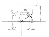
本出願によれば、二次部品1’の位置認識部に向けてエネルギーを伝送するための本発明の装置の一次部品1は、一次コイル10および二次コイル10’の漂遊磁場を測定する少なくとも1つの磁界センサーを有している。図示されている例示的な実施形態では、4つの補助コイル30a、30b、30c、30dが、磁界センサーとして使用され、前板3の4つの象限にコイル10に隣接して配置されている。補助コイル30a、30c、30b、30dの2つずつは、コイル10の中心点に対して互いに対称となっている。図2の断面図では、4つの補助コイル30a、30b、30c、30dの位置が容易に認識可能となっている。以下において、補助コイル30a、30b、30c、30dの個別の1つについて明示的に言及(特定)しない場合、補助コイル30a、30b、30c、30dは参照数字30により包括的に表される。
According to the present application, the
補助コイル30は受信コイルであり、この受信コイルにおいて、信号が、一次コイル10および二次コイル10’の漂遊磁場により誘発、調整され、一次部品1のプレートスラブ20上の評価回路により評価される。補助コイル30内で誘発された信号のレベルは、一次部品1と二次部品1’との間の間隔z0ならびにx方向およびy方向からなる側面方向のオフセットの関数で表される。このことは、図3および図4を参照して以下により詳細に説明されている。
The
図3には、エネルギーを誘導伝送するための装置の一次部品1および二次部品1’が側面に沿って(側面方向に)オフセットされている状態が概略的に示されている。直角座標では、オフセットは、x方向にx0で表され、y方向にy0で表されている。加えて、間隔z0は、この図では視認できないが、一次部品1と二次部品1’との間に存在していると考えられる。側面方向のオフセットx0、y0については、極座標で表すこともでき、その場合、一次コイル10の中心点と二次コイル10’の中心点との間の動径r0と、間隔ベクトルとx軸との間の偏角φとにより表すこともできる。
FIG. 3 schematically shows a state in which the
図4には、間隔z0が一定で、動径r0が一定である場合、二次部品1’が一次部品1のz軸を中心として円状に移動した量に応じて4つの補助コイル30における信号の振幅31(ここでは、電圧振幅)がどのように変化するかが例示的に示されている。補助コイル30a、30b、30c、30dの具体的に得られた信号の振幅31a、31b、31c、31dが偏角φの関数として示されている。第一の近似では、信号の振幅31が偏角φを関数とする特定の正弦波に依存する特性を有することが分かった。これらの正弦波曲線はすべて同じ振幅u^と同じオフセットu0とを有している。
In FIG. 4, when the distance z0 is constant and the moving radius r0 is constant, the four
記載の振幅u^は主に動径r0の大きさの関数であり、オフセットu0は主に一次部品1と二次部品1’との間の間隔z0の関数である。一次コイル10および二次コイル10’にフェライト磁心11、11’を用いると得られる特定の依存性は、動径r0(側面方向のオフセットx0、y0)ならびに軸方向の間隔z0の分離を容易にし、有利に働く。フェライト磁心のない空芯コイルを用いた場合、測定される信号振幅が、一次コイルと二次コイルとの間の軸方向の間隔が大きくなるにつれて周囲の金属物体に対して、また、隣接する他のコンポーネントの漂遊磁場に対してますます強い影響を及ぼし、軸方向の間隔z0の測定を困難なものとする。
The described amplitude u is mainly a function of the radius r0, and the offset u0 is mainly a function of the distance z0 between the
両方の場合において、依存性は、動径r0および間隔z0の値が(一次コイル10および二次コイル10’の大きさに対して)小さい場合には実質的に線形である。これらの線形依存する比例定数は、エネルギーを伝送するための装置について、一次コイル10に流れる電流レベルを一定にして既知の動径r0および既知の間隔z0で複数回測定することにより前もって求めることができる。間隔を求めるために記録された測定値は次に一次コイル10を流れる電流レベルを考慮に入れて比例定数の記録条件に合わせてスケーリングされる。
In both cases, the dependence is substantially linear when the values of radial r0 and spacing z0 are small (relative to the size of
エネルギーの伝送用の装置の動作時、未知の間隔z0、未知の動径r0および未知の偏角φを求めるために、まず4つの信号振幅レベル31a、31b、31c、31dが測定される。
In operation of the device for energy transmission, four
対向する補助コイル30a、30cまたは対向する補助コイル30b、30dの2つの信号振幅31a、31bまたは2つの信号振幅31c、31dを加算することにより信号振幅31の正弦波成分が互いに打ち消し合うため、オフセットu0の大きさを求めることができる。また、良好な信号対雑音比を得るために、対向する補助コイルのペア31a、31cおよび対向する補助コイルのペア31b、31dの両方のペアについて、すなわち最終的に4つの信号振幅31a−31dをすべて加算してオフセットu0を求めるようにすることができる。間隔z0の大きさについては、オフセットの大きさu0から以前に決定された比例定数と一次コイル10を流れる実際の電流に合わせたスケーリングとを用いて求めることができる。
Since the two
また、偏角φの大きさについては、2つの対向する補助コイル30a、30cの2つの対向する補助コイル31a、31cの差ならびに2つの対向する補助コイル30b、30dの2つの対向する補助コイル31b、31dの差を角度の関数としてプロットすることにより求めることができる。
Further, regarding the magnitude of the deflection angle φ, the difference between the two opposing
図5には、2つの信号の差u’である差振幅31e、31fが再び偏角φの関数として示されている。差信号31eは信号振幅31a、31cから形成され、差信号31fは信号振幅31b、31dから形成されている。
In FIG. 5, the
2つの差信号31e、31fは正弦波として伝搬され、位相シフトは90°である。差信号31e、31fにはオフセットがなく、差信号31e、31fの振幅はオフセット、すなわち動径r0のみに依存する。動径r0の大きさは、差信号31e、31fの振幅のうちの1つから一次コイル10を流れる実際の電流のレベルに合わせてスケーリングした後の前もって求められた比例定数を用いて得られる。差信号31e、31fの振幅は信号振幅31a−dの振幅u^より2倍大きくなっている。
The two
最後に、偏角φ、すなわちオフセットの方向について、差信号31e、31fのうちの一方の位相位置から三角関数により求めることができる。差信号31e、31fの位相位置は、差信号31e、31fの0スループット位置から求めることができる。 Finally, the declination angle φ, that is, the direction of the offset can be obtained from the phase position of one of the difference signals 31e and 31f by a trigonometric function. The phase positions of the difference signals 31e and 31f can be obtained from the zero throughput position of the difference signals 31e and 31f.
要約すると、本出願によれば、一次部品1と二次部品1’との間の側面方向のオフセットの動径r0および方向(偏角φ)は、4つの補助コイル30を用いて、一次コイル10および二次コイル10’の漂遊磁場により4つの補助コイル30内に誘発される信号のレベルと、一次部品1と二次部品1’との間の間隔z0とから求めることができる。また、側面方向のオフセットについての情報に関しては、極座標(動径r0、偏角φ)から直交座標(x0、y0)を計算し、示すこともできる。
In summary, according to the present application, the radial radius r0 and the direction (deflection angle φ) of the offset in the lateral direction between the
側面方向のオフセットおよび間隔に関する情報を一次部品1のデータチャネルにより示すようにすることもできる。この情報を用いることにより、エネルギーを伝送する装置を用いるロボットにおいてエラーを示す一次部品1と二次部品1’との間の相互の位置関係についての問題をたとえばオートメーションコントロールにより認識することができることが分かる。さらに、求められた側面方向のオフセット(x0、y0またはr0)および/または求められた間隔z0が一定の境界値を上回る場合、一次部品1から二次部品1’へのエネルギーの伝送が中断されるまたはもともと初期段階において初めから開始されないようにすることもできる。境界値は、表の形態を有していてもよいし、または、同時に存在することが可能な側面方向のオフセットと間隔との組み合わせの範囲の関数関係が考慮に入れられてもよい。
Information about the offset and spacing in the lateral direction can also be indicated by the data channel of the
記載の方法は、二次側が不正確に配置されたことが一次側で認識されるという利点を有している。一次部品1の信頼できる動作を保証するために二次部品1’から一次部品1へ返答する必要はない。
The described method has the advantage that the primary side recognizes that the secondary side has been placed incorrectly. There is no need to reply from the
プラグ・ソケットコネクタの他の実施形態では、位置合わせに関して、二次部品から一次部品への返答に基づく安全機構がさらに用いられるようになっている場合もある。 In other embodiments of the plug and socket connector, a safety mechanism based on a response from the secondary part to the primary part may be further used for alignment.
プラグ・ソケットコネクタの他の実施形態では、共信周波数を通じた共振回路の離調を用いて、また任意選択的に、一次コイルを流れる電流を用いて、側面方向のオフセットおよび/または間隔についての情報が求められるようにさらになっている場合もある。このさらなる測定は、さらに伝送の安全性を上げるためのものとして先に記載された補助コイル30を用いて間隔を求める方法である管理測定として働きうるものである。
In another embodiment of the plug and socket connector, the detuning of the resonant circuit through the common frequency, and optionally using the current through the primary coil, for lateral offset and / or spacing. In some cases, more information is required. This further measurement can serve as a management measurement, which is a method for determining the spacing using the
1 一次部品
1’二次部品
2、2’ハウジング
3、3’カバープレート
4、4’接続ケーブル
5、5’ケーブル案内口
10 一次コイル
10’二次コイル
11、11’フェライト磁心
12、12’外縁部
13、13’内側ドーム
14、14’熱伝導マット
20、20’プレートスラブ
21、21’電子構造要素
30a−d 補助コイル
31a−d 信号振幅
31e、31f 差信号
x0、y0 側面方向のオフセット(直交座標)
r0 動径(極座標)
φ 偏角(極座標)
z0 間隔
u 信号振幅のレベル
u^ 振幅
u0 オフセット
DESCRIPTION OF
r0 radius (polar coordinates)
φ declination (polar coordinates)
z0 interval u signal amplitude level u ^ amplitude u0 offset
Claims (13)
前記デバイスが、前記一次部品の前記コイル(10)の軸に沿って前記二次部品(1’)から前記一次部品(1)までの間隔(z0)を前記少なくとも1つの磁界センサーにより測定された前記磁界を用いて求めるようにさらに構成されてなる、装置。 A device for inductively transmitting energy from a primary part (1) having at least one coil (10) to a secondary part (1 ') having at least one coil (10'), comprising: At least one coil (10) and the at least one coil (10 ′) are inductively coupled to each other, and the primary part (1) and / or the secondary part (1 ′) has at least one magnetic field sensor. The primary part (1) and / or the secondary part (1 ′) are generated by the coil (10) and the coil (10 ′) and measured using the at least one magnetic field sensor. An apparatus configured to determine a lateral offset of the secondary part (1 ′) relative to the primary part (1) using a magnetic field
The device was measured by the at least one magnetic field sensor for a distance (z0) from the secondary part (1 ′) to the primary part (1) along the axis of the coil (10) of the primary part. An apparatus further configured to determine using the magnetic field.
前記少なくとも1つの磁界センサーにより測定される磁界を用いて、前記一次コイル(10)の軸に沿った前記二次部品(1’)から前記一次部品(1)までの間隔(z0)がさらに求められることを特徴とする、動作方法。 An operating method for a device for inductively transmitting energy from a coil (10) of a primary part (1) to a coil (10 ') of a secondary part (1'), comprising said coil (10) and A method of operation wherein an offset in the lateral direction of the secondary part (1 ') relative to the primary part (1) is determined using a magnetic field generated by the coil (10') and measured by at least one magnetic field sensor. In
Using the magnetic field measured by the at least one magnetic field sensor, an interval (z0) from the secondary part (1 ′) to the primary part (1) along the axis of the primary coil (10) is further obtained. A method of operation, characterized in that
Applications Claiming Priority (5)
| Application Number | Priority Date | Filing Date | Title |
|---|---|---|---|
| DE102015105359 | 2015-04-09 | ||
| DE102015105359.4 | 2015-04-09 | ||
| DE102015113723.2A DE102015113723A1 (en) | 2015-04-09 | 2015-08-19 | Apparatus for contactless inductive energy transmission and method of operation for such a device |
| DE102015113723.2 | 2015-08-19 | ||
| PCT/EP2016/057826 WO2016162520A1 (en) | 2015-04-09 | 2016-04-08 | Apparatus for contactless inductive energy transmission and operating method for such an apparatus |
Publications (1)
| Publication Number | Publication Date |
|---|---|
| JP2018512837A true JP2018512837A (en) | 2018-05-17 |
Family
ID=56986417
Family Applications (1)
| Application Number | Title | Priority Date | Filing Date |
|---|---|---|---|
| JP2017552961A Pending JP2018512837A (en) | 2015-04-09 | 2016-04-08 | Device for inductively transmitting energy in a contactless manner and method of operating such a device |
Country Status (7)
| Country | Link |
|---|---|
| US (1) | US10505399B2 (en) |
| EP (1) | EP3281275B1 (en) |
| JP (1) | JP2018512837A (en) |
| CN (1) | CN107431386B (en) |
| DE (1) | DE102015113723A1 (en) |
| ES (1) | ES2898674T3 (en) |
| WO (1) | WO2016162520A1 (en) |
Families Citing this family (9)
| Publication number | Priority date | Publication date | Assignee | Title |
|---|---|---|---|---|
| CN108297704A (en) * | 2017-01-11 | 2018-07-20 | 宁波轩悦行电动汽车服务有限公司 | Electric vehicle is returned the car processing system |
| DE102017108302A1 (en) | 2017-04-19 | 2018-10-25 | Weidmüller Interface GmbH & Co. KG | Device for contactless inductive energy transmission and method for operating the device |
| DE202017107131U1 (en) * | 2017-11-24 | 2019-01-10 | Bombardier Primove Gmbh | Movable part of a device for inductive energy transmission and device for inductive energy transmission |
| US10790711B2 (en) * | 2017-12-21 | 2020-09-29 | Korea Advanced Institute Of Science And Technology | Magnetic field generating apparatus having cannon shape and magnetic field generation method thereof |
| DE102018120779B3 (en) | 2018-08-24 | 2019-12-12 | Phoenix Contact Gmbh & Co. Kg | Contactless PoE connection system |
| CN109883309B (en) * | 2019-01-28 | 2021-04-27 | 中国船舶重工集团公司第七一五研究所 | Cable in-place sensing device based on magnetic induction principle |
| CN109895643B (en) * | 2019-02-26 | 2020-07-07 | 浙江大学 | Online electric automobile wireless charging positioning system based on differential inductance |
| US11505077B2 (en) * | 2020-05-27 | 2022-11-22 | Toyota Motor Engineering & Manufacturing North America, Inc. | Systems and methods for wireless vehicle power transfer and misalignment estimation |
| CN114050665B (en) * | 2022-01-17 | 2022-04-12 | 广东电网有限责任公司佛山供电局 | Working power supply for three-phase cable on-line monitoring |
Citations (7)
| Publication number | Priority date | Publication date | Assignee | Title |
|---|---|---|---|---|
| JP2009089465A (en) * | 2007-09-27 | 2009-04-23 | Panasonic Corp | Charger and charging system |
| JP2010130729A (en) * | 2008-11-25 | 2010-06-10 | Canon Inc | Charging equipment, transmission equipment, and noncontact charging system |
| JP2012034546A (en) * | 2010-08-03 | 2012-02-16 | Panasonic Corp | Wireless power transmission system |
| JP2012532584A (en) * | 2009-07-06 | 2012-12-13 | ボストン サイエンティフィック ニューロモデュレイション コーポレイション | Improved external charger for medical implantable devices using magnetic field sensing coils to improve coupling |
| JP2013031315A (en) * | 2011-07-29 | 2013-02-07 | Toko Inc | Wireless power transmission equipment and relative position detection method |
| JP2014518607A (en) * | 2011-04-13 | 2014-07-31 | クアルコム,インコーポレイテッド | Antenna alignment and vehicle guidance for wireless charging of electric vehicles |
| JP2015037336A (en) * | 2013-08-12 | 2015-02-23 | 本田技研工業株式会社 | Non-contact charger |
Family Cites Families (11)
| Publication number | Priority date | Publication date | Assignee | Title |
|---|---|---|---|---|
| JP4547026B2 (en) | 2005-04-12 | 2010-09-22 | ジーメンス エレクトロニクス アセンブリー システムズ ゲゼルシャフト ミット ベシュレンクテル ハフツング ウント コンパニー コマンディートゲゼルシャフト | Primary part for contactless current supply, monitoring the operating state of the secondary part |
| WO2009041058A1 (en) * | 2007-09-27 | 2009-04-02 | Panasonic Corporation | Electronic device, recharger and recharging system |
| US20130207893A1 (en) * | 2009-04-29 | 2013-08-15 | Kye Systems Corp. | Positioning input system with wireless charging function, and device |
| JP5770589B2 (en) * | 2011-09-30 | 2015-08-26 | 東光株式会社 | Wireless power transmission apparatus and relative position detection method |
| DE102011056265A1 (en) | 2011-12-12 | 2013-06-13 | Weidmüller Interface GmbH & Co. KG | Plug-in device for contactless inductive power transmission and operating method for such a plug-in device |
| FR2989529B1 (en) * | 2012-04-12 | 2016-04-15 | Continental Automotive France | METHOD AND MAGNETIC COUPLING LOAD BENCH |
| JP6059522B2 (en) * | 2012-04-17 | 2017-01-11 | 日東電工株式会社 | Wireless power supply system, power supply device, power reception device, and magnetic field space forming method |
| KR101949127B1 (en) | 2013-08-01 | 2019-02-18 | 삼성전자주식회사 | Method and apparatus for wireless energy transmission with hybrid synchronization scheme |
| US9537353B1 (en) * | 2014-06-03 | 2017-01-03 | Apple Inc. | Methods for detecting mated coils |
| US9829599B2 (en) * | 2015-03-23 | 2017-11-28 | Schneider Electric USA, Inc. | Sensor and method for foreign object detection in induction electric charger |
| US10034704B2 (en) * | 2015-06-30 | 2018-07-31 | Ethicon Llc | Surgical instrument with user adaptable algorithms |
-
2015
- 2015-08-19 DE DE102015113723.2A patent/DE102015113723A1/en not_active Withdrawn
-
2016
- 2016-04-08 EP EP16715848.4A patent/EP3281275B1/en active Active
- 2016-04-08 WO PCT/EP2016/057826 patent/WO2016162520A1/en active Application Filing
- 2016-04-08 ES ES16715848T patent/ES2898674T3/en active Active
- 2016-04-08 JP JP2017552961A patent/JP2018512837A/en active Pending
- 2016-04-08 US US15/557,265 patent/US10505399B2/en active Active
- 2016-04-08 CN CN201680018030.2A patent/CN107431386B/en active Active
Patent Citations (7)
| Publication number | Priority date | Publication date | Assignee | Title |
|---|---|---|---|---|
| JP2009089465A (en) * | 2007-09-27 | 2009-04-23 | Panasonic Corp | Charger and charging system |
| JP2010130729A (en) * | 2008-11-25 | 2010-06-10 | Canon Inc | Charging equipment, transmission equipment, and noncontact charging system |
| JP2012532584A (en) * | 2009-07-06 | 2012-12-13 | ボストン サイエンティフィック ニューロモデュレイション コーポレイション | Improved external charger for medical implantable devices using magnetic field sensing coils to improve coupling |
| JP2012034546A (en) * | 2010-08-03 | 2012-02-16 | Panasonic Corp | Wireless power transmission system |
| JP2014518607A (en) * | 2011-04-13 | 2014-07-31 | クアルコム,インコーポレイテッド | Antenna alignment and vehicle guidance for wireless charging of electric vehicles |
| JP2013031315A (en) * | 2011-07-29 | 2013-02-07 | Toko Inc | Wireless power transmission equipment and relative position detection method |
| JP2015037336A (en) * | 2013-08-12 | 2015-02-23 | 本田技研工業株式会社 | Non-contact charger |
Also Published As
| Publication number | Publication date |
|---|---|
| US10505399B2 (en) | 2019-12-10 |
| CN107431386A (en) | 2017-12-01 |
| DE102015113723A1 (en) | 2016-10-13 |
| EP3281275A1 (en) | 2018-02-14 |
| US20180062444A1 (en) | 2018-03-01 |
| ES2898674T3 (en) | 2022-03-08 |
| EP3281275B1 (en) | 2021-10-13 |
| CN107431386B (en) | 2021-05-07 |
| WO2016162520A1 (en) | 2016-10-13 |
Similar Documents
| Publication | Publication Date | Title |
|---|---|---|
| JP2018512837A (en) | Device for inductively transmitting energy in a contactless manner and method of operating such a device | |
| US11004597B2 (en) | Detection apparatus, power supply system, and method of controlling detection apparatus | |
| JP6466624B2 (en) | Cable unit for connecting devices and enabling wireless exchange of data and / or power between devices | |
| JP6975136B2 (en) | Battery module for wireless exchange of data and power | |
| JP4772744B2 (en) | Signal transmission coil communication device for non-contact power feeding device | |
| JP5669949B2 (en) | Non-contact power feeding device | |
| JP6684897B2 (en) | Connector and device for wireless transmission of data and / or power | |
| CN107430011A (en) | For the device and correlation technique using wireless power emitter detection flux fields characteristic | |
| JP2018526121A5 (en) | ||
| JP2014225962A (en) | Detector, power supply system and control method of detector | |
| JP2014225963A (en) | Detector, power supply system and control method of detector | |
| JP2011072074A (en) | Noncontact charging system | |
| EP2659496B1 (en) | Device for transfer of electrical signals and/or electrical energy | |
| US10938251B1 (en) | Wireless power mode switching | |
| CN108012575B (en) | Device for wireless transmission of data and power | |
| WO2021257265A1 (en) | Wireless charging system with simultaneous wireless power transfer at different frequencies | |
| JP2017104007A (en) | Contactless connector system with feedback from secondary side | |
| CN108140477B (en) | Stackable connector and apparatus for wireless transmission of power | |
| EP4050806A1 (en) | Small home appliance, and method for performing communication in small home appliance | |
| Kim et al. | Application of FRA to improve the design and maintenance of wireless power transfer systems | |
| Wu et al. | Analytical computation of mutual inductance between two rectangular spiral coils with misalignments for wireless power applications | |
| Inada et al. | Arbitrary magnetic field control technique by multi-coil transmitter voltage phase shifting for omni-directional free-positioning magnetic resonance wireless power delivery | |
| Vaheeda et al. | In-vehicle sensing system to sense the ground pad configuration in the V2G mode of EV | |
| Curran et al. | Modeling and characterization of PCB coils for inductive wireless charging |
Legal Events
| Date | Code | Title | Description |
|---|---|---|---|
| A621 | Written request for application examination |
Free format text: JAPANESE INTERMEDIATE CODE: A621 Effective date: 20180206 |
|
| A977 | Report on retrieval |
Free format text: JAPANESE INTERMEDIATE CODE: A971007 Effective date: 20181212 |
|
| A131 | Notification of reasons for refusal |
Free format text: JAPANESE INTERMEDIATE CODE: A131 Effective date: 20181218 |
|
| A601 | Written request for extension of time |
Free format text: JAPANESE INTERMEDIATE CODE: A601 Effective date: 20190312 |
|
| A521 | Request for written amendment filed |
Free format text: JAPANESE INTERMEDIATE CODE: A523 Effective date: 20190617 |
|
| A131 | Notification of reasons for refusal |
Free format text: JAPANESE INTERMEDIATE CODE: A131 Effective date: 20191126 |
|
| A02 | Decision of refusal |
Free format text: JAPANESE INTERMEDIATE CODE: A02 Effective date: 20200623 |