JP2018512544A - Vacuum insulation panel and method for manufacturing the same - Google Patents
Vacuum insulation panel and method for manufacturing the same Download PDFInfo
- Publication number
- JP2018512544A JP2018512544A JP2017548885A JP2017548885A JP2018512544A JP 2018512544 A JP2018512544 A JP 2018512544A JP 2017548885 A JP2017548885 A JP 2017548885A JP 2017548885 A JP2017548885 A JP 2017548885A JP 2018512544 A JP2018512544 A JP 2018512544A
- Authority
- JP
- Japan
- Prior art keywords
- envelope
- metal foil
- vacuum
- insulation panel
- core
- Prior art date
- Legal status (The legal status is an assumption and is not a legal conclusion. Google has not performed a legal analysis and makes no representation as to the accuracy of the status listed.)
- Pending
Links
- 238000009413 insulation Methods 0.000 title claims abstract description 70
- 238000000034 method Methods 0.000 title claims abstract description 26
- 238000004519 manufacturing process Methods 0.000 title claims abstract description 18
- 229910052751 metal Inorganic materials 0.000 claims abstract description 222
- 239000002184 metal Substances 0.000 claims abstract description 222
- 239000011888 foil Substances 0.000 claims abstract description 215
- 230000008569 process Effects 0.000 claims abstract description 11
- -1 polyethylene Polymers 0.000 claims description 50
- 239000004698 Polyethylene Substances 0.000 claims description 35
- 229920000573 polyethylene Polymers 0.000 claims description 35
- 239000000463 material Substances 0.000 claims description 27
- 238000010438 heat treatment Methods 0.000 claims description 25
- 229910052782 aluminium Inorganic materials 0.000 claims description 21
- XAGFODPZIPBFFR-UHFFFAOYSA-N aluminium Chemical compound [Al] XAGFODPZIPBFFR-UHFFFAOYSA-N 0.000 claims description 21
- 229920000642 polymer Polymers 0.000 claims description 13
- 239000012815 thermoplastic material Substances 0.000 claims description 13
- 239000004715 ethylene vinyl alcohol Substances 0.000 claims description 12
- 229920001169 thermoplastic Polymers 0.000 claims description 12
- 239000004743 Polypropylene Substances 0.000 claims description 11
- 229920001155 polypropylene Polymers 0.000 claims description 11
- 239000000853 adhesive Substances 0.000 claims description 8
- 230000001070 adhesive effect Effects 0.000 claims description 8
- 229920001577 copolymer Polymers 0.000 claims description 8
- 229920001684 low density polyethylene Polymers 0.000 claims description 8
- 239000004702 low-density polyethylene Substances 0.000 claims description 8
- 239000004416 thermosoftening plastic Substances 0.000 claims description 8
- RZXDTJIXPSCHCI-UHFFFAOYSA-N hexa-1,5-diene-2,5-diol Chemical compound OC(=C)CCC(O)=C RZXDTJIXPSCHCI-UHFFFAOYSA-N 0.000 claims description 7
- 239000000203 mixture Substances 0.000 claims description 6
- 229920010126 Linear Low Density Polyethylene (LLDPE) Polymers 0.000 claims description 4
- 229920010741 Ultra High Molecular Weight Polyethylene (UHMWPE) Polymers 0.000 claims description 4
- 239000005033 polyvinylidene chloride Substances 0.000 claims description 4
- 229920002803 thermoplastic polyurethane Polymers 0.000 claims description 4
- 239000011248 coating agent Substances 0.000 claims description 2
- 238000000576 coating method Methods 0.000 claims description 2
- 230000005540 biological transmission Effects 0.000 description 30
- 239000011104 metalized film Substances 0.000 description 23
- VYPSYNLAJGMNEJ-UHFFFAOYSA-N Silicium dioxide Chemical compound O=[Si]=O VYPSYNLAJGMNEJ-UHFFFAOYSA-N 0.000 description 15
- 229920000139 polyethylene terephthalate Polymers 0.000 description 12
- 239000005020 polyethylene terephthalate Substances 0.000 description 12
- 239000010408 film Substances 0.000 description 10
- QVGXLLKOCUKJST-UHFFFAOYSA-N atomic oxygen Chemical compound [O] QVGXLLKOCUKJST-UHFFFAOYSA-N 0.000 description 9
- 230000004888 barrier function Effects 0.000 description 9
- 229910052760 oxygen Inorganic materials 0.000 description 9
- 239000001301 oxygen Substances 0.000 description 9
- 239000000835 fiber Substances 0.000 description 8
- 230000000694 effects Effects 0.000 description 7
- XEEYBQQBJWHFJM-UHFFFAOYSA-N Iron Chemical compound [Fe] XEEYBQQBJWHFJM-UHFFFAOYSA-N 0.000 description 6
- 230000032683 aging Effects 0.000 description 6
- 229910021485 fumed silica Inorganic materials 0.000 description 6
- 239000012774 insulation material Substances 0.000 description 6
- 238000002844 melting Methods 0.000 description 6
- 230000008018 melting Effects 0.000 description 6
- XLYOFNOQVPJJNP-UHFFFAOYSA-N water Chemical compound O XLYOFNOQVPJJNP-UHFFFAOYSA-N 0.000 description 6
- 239000011810 insulating material Substances 0.000 description 5
- 239000003605 opacifier Substances 0.000 description 5
- 230000035699 permeability Effects 0.000 description 5
- 238000007789 sealing Methods 0.000 description 5
- 229920003023 plastic Polymers 0.000 description 4
- 239000004033 plastic Substances 0.000 description 4
- 229920006254 polymer film Polymers 0.000 description 4
- 239000000377 silicon dioxide Substances 0.000 description 4
- 229920000219 Ethylene vinyl alcohol Polymers 0.000 description 3
- 239000006260 foam Substances 0.000 description 3
- 239000003365 glass fiber Substances 0.000 description 3
- 230000006872 improvement Effects 0.000 description 3
- 229910052742 iron Inorganic materials 0.000 description 3
- 239000002245 particle Substances 0.000 description 3
- 239000000843 powder Substances 0.000 description 3
- RZVAJINKPMORJF-UHFFFAOYSA-N Acetaminophen Chemical compound CC(=O)NC1=CC=C(O)C=C1 RZVAJINKPMORJF-UHFFFAOYSA-N 0.000 description 2
- UQSXHKLRYXJYBZ-UHFFFAOYSA-N Iron oxide Chemical compound [Fe]=O UQSXHKLRYXJYBZ-UHFFFAOYSA-N 0.000 description 2
- 229920000134 Metallised film Polymers 0.000 description 2
- GWEVSGVZZGPLCZ-UHFFFAOYSA-N Titan oxide Chemical compound O=[Ti]=O GWEVSGVZZGPLCZ-UHFFFAOYSA-N 0.000 description 2
- 229920001038 ethylene copolymer Polymers 0.000 description 2
- 239000012467 final product Substances 0.000 description 2
- 229910010272 inorganic material Inorganic materials 0.000 description 2
- 239000011147 inorganic material Substances 0.000 description 2
- 238000001465 metallisation Methods 0.000 description 2
- 239000012229 microporous material Substances 0.000 description 2
- 239000011236 particulate material Substances 0.000 description 2
- 229910001562 pearlite Inorganic materials 0.000 description 2
- 230000035515 penetration Effects 0.000 description 2
- 239000002861 polymer material Substances 0.000 description 2
- 239000000047 product Substances 0.000 description 2
- 230000009467 reduction Effects 0.000 description 2
- HBMJWWWQQXIZIP-UHFFFAOYSA-N silicon carbide Chemical compound [Si+]#[C-] HBMJWWWQQXIZIP-UHFFFAOYSA-N 0.000 description 2
- 229910010271 silicon carbide Inorganic materials 0.000 description 2
- 239000010935 stainless steel Substances 0.000 description 2
- 229910001220 stainless steel Inorganic materials 0.000 description 2
- 238000002834 transmittance Methods 0.000 description 2
- RNFJDJUURJAICM-UHFFFAOYSA-N 2,2,4,4,6,6-hexaphenoxy-1,3,5-triaza-2$l^{5},4$l^{5},6$l^{5}-triphosphacyclohexa-1,3,5-triene Chemical compound N=1P(OC=2C=CC=CC=2)(OC=2C=CC=CC=2)=NP(OC=2C=CC=CC=2)(OC=2C=CC=CC=2)=NP=1(OC=1C=CC=CC=1)OC1=CC=CC=C1 RNFJDJUURJAICM-UHFFFAOYSA-N 0.000 description 1
- 229920002799 BoPET Polymers 0.000 description 1
- OKTJSMMVPCPJKN-UHFFFAOYSA-N Carbon Chemical compound [C] OKTJSMMVPCPJKN-UHFFFAOYSA-N 0.000 description 1
- 101000953492 Homo sapiens Inositol hexakisphosphate and diphosphoinositol-pentakisphosphate kinase 1 Proteins 0.000 description 1
- 102100037739 Inositol hexakisphosphate and diphosphoinositol-pentakisphosphate kinase 1 Human genes 0.000 description 1
- 239000005909 Kieselgur Substances 0.000 description 1
- 229920005830 Polyurethane Foam Polymers 0.000 description 1
- 229910000831 Steel Inorganic materials 0.000 description 1
- 239000011358 absorbing material Substances 0.000 description 1
- 229910045601 alloy Inorganic materials 0.000 description 1
- 239000000956 alloy Substances 0.000 description 1
- 239000011230 binding agent Substances 0.000 description 1
- 230000015572 biosynthetic process Effects 0.000 description 1
- IKZZIQXKLWDPCD-UHFFFAOYSA-N but-1-en-2-ol Chemical compound CCC(O)=C IKZZIQXKLWDPCD-UHFFFAOYSA-N 0.000 description 1
- 229910052799 carbon Inorganic materials 0.000 description 1
- 239000006229 carbon black Substances 0.000 description 1
- 230000002301 combined effect Effects 0.000 description 1
- 238000001816 cooling Methods 0.000 description 1
- 230000006837 decompression Effects 0.000 description 1
- 230000007547 defect Effects 0.000 description 1
- 230000000593 degrading effect Effects 0.000 description 1
- 239000003063 flame retardant Substances 0.000 description 1
- 239000006261 foam material Substances 0.000 description 1
- 239000011491 glass wool Substances 0.000 description 1
- 229920001903 high density polyethylene Polymers 0.000 description 1
- 239000004700 high-density polyethylene Substances 0.000 description 1
- 230000001771 impaired effect Effects 0.000 description 1
- SZVJSHCCFOBDDC-UHFFFAOYSA-N iron(II,III) oxide Inorganic materials O=[Fe]O[Fe]O[Fe]=O SZVJSHCCFOBDDC-UHFFFAOYSA-N 0.000 description 1
- 230000007774 longterm Effects 0.000 description 1
- 238000012423 maintenance Methods 0.000 description 1
- 239000000155 melt Substances 0.000 description 1
- 239000011140 metalized polyester Substances 0.000 description 1
- 150000002739 metals Chemical class 0.000 description 1
- 239000011368 organic material Substances 0.000 description 1
- 230000003647 oxidation Effects 0.000 description 1
- 238000007254 oxidation reaction Methods 0.000 description 1
- 239000010451 perlite Substances 0.000 description 1
- 235000019362 perlite Nutrition 0.000 description 1
- ISWSIDIOOBJBQZ-UHFFFAOYSA-N phenol group Chemical group C1(=CC=CC=C1)O ISWSIDIOOBJBQZ-UHFFFAOYSA-N 0.000 description 1
- 229920000728 polyester Polymers 0.000 description 1
- 229920006327 polystyrene foam Polymers 0.000 description 1
- 239000011496 polyurethane foam Substances 0.000 description 1
- 238000005057 refrigeration Methods 0.000 description 1
- 239000012783 reinforcing fiber Substances 0.000 description 1
- 238000007655 standard test method Methods 0.000 description 1
- 239000010959 steel Substances 0.000 description 1
- 238000005728 strengthening Methods 0.000 description 1
- 239000000758 substrate Substances 0.000 description 1
- 239000004408 titanium dioxide Substances 0.000 description 1
Images


Classifications
-
- B—PERFORMING OPERATIONS; TRANSPORTING
- B32—LAYERED PRODUCTS
- B32B—LAYERED PRODUCTS, i.e. PRODUCTS BUILT-UP OF STRATA OF FLAT OR NON-FLAT, e.g. CELLULAR OR HONEYCOMB, FORM
- B32B3/00—Layered products comprising a layer with external or internal discontinuities or unevennesses, or a layer of non-planar form; Layered products having particular features of form
- B32B3/02—Layered products comprising a layer with external or internal discontinuities or unevennesses, or a layer of non-planar form; Layered products having particular features of form characterised by features of form at particular places, e.g. in edge regions
- B32B3/04—Layered products comprising a layer with external or internal discontinuities or unevennesses, or a layer of non-planar form; Layered products having particular features of form characterised by features of form at particular places, e.g. in edge regions characterised by at least one layer folded at the edge, e.g. over another layer ; characterised by at least one layer enveloping or enclosing a material
-
- B—PERFORMING OPERATIONS; TRANSPORTING
- B32—LAYERED PRODUCTS
- B32B—LAYERED PRODUCTS, i.e. PRODUCTS BUILT-UP OF STRATA OF FLAT OR NON-FLAT, e.g. CELLULAR OR HONEYCOMB, FORM
- B32B15/00—Layered products comprising a layer of metal
- B32B15/04—Layered products comprising a layer of metal comprising metal as the main or only constituent of a layer, which is next to another layer of the same or of a different material
- B32B15/046—Layered products comprising a layer of metal comprising metal as the main or only constituent of a layer, which is next to another layer of the same or of a different material of foam
-
- B—PERFORMING OPERATIONS; TRANSPORTING
- B32—LAYERED PRODUCTS
- B32B—LAYERED PRODUCTS, i.e. PRODUCTS BUILT-UP OF STRATA OF FLAT OR NON-FLAT, e.g. CELLULAR OR HONEYCOMB, FORM
- B32B15/00—Layered products comprising a layer of metal
- B32B15/04—Layered products comprising a layer of metal comprising metal as the main or only constituent of a layer, which is next to another layer of the same or of a different material
- B32B15/08—Layered products comprising a layer of metal comprising metal as the main or only constituent of a layer, which is next to another layer of the same or of a different material of synthetic resin
- B32B15/085—Layered products comprising a layer of metal comprising metal as the main or only constituent of a layer, which is next to another layer of the same or of a different material of synthetic resin comprising polyolefins
-
- B—PERFORMING OPERATIONS; TRANSPORTING
- B32—LAYERED PRODUCTS
- B32B—LAYERED PRODUCTS, i.e. PRODUCTS BUILT-UP OF STRATA OF FLAT OR NON-FLAT, e.g. CELLULAR OR HONEYCOMB, FORM
- B32B15/00—Layered products comprising a layer of metal
- B32B15/04—Layered products comprising a layer of metal comprising metal as the main or only constituent of a layer, which is next to another layer of the same or of a different material
- B32B15/08—Layered products comprising a layer of metal comprising metal as the main or only constituent of a layer, which is next to another layer of the same or of a different material of synthetic resin
- B32B15/09—Layered products comprising a layer of metal comprising metal as the main or only constituent of a layer, which is next to another layer of the same or of a different material of synthetic resin comprising polyesters
-
- B—PERFORMING OPERATIONS; TRANSPORTING
- B32—LAYERED PRODUCTS
- B32B—LAYERED PRODUCTS, i.e. PRODUCTS BUILT-UP OF STRATA OF FLAT OR NON-FLAT, e.g. CELLULAR OR HONEYCOMB, FORM
- B32B15/00—Layered products comprising a layer of metal
- B32B15/14—Layered products comprising a layer of metal next to a fibrous or filamentary layer
-
- B—PERFORMING OPERATIONS; TRANSPORTING
- B32—LAYERED PRODUCTS
- B32B—LAYERED PRODUCTS, i.e. PRODUCTS BUILT-UP OF STRATA OF FLAT OR NON-FLAT, e.g. CELLULAR OR HONEYCOMB, FORM
- B32B15/00—Layered products comprising a layer of metal
- B32B15/16—Layered products comprising a layer of metal next to a particulate layer
-
- B—PERFORMING OPERATIONS; TRANSPORTING
- B32—LAYERED PRODUCTS
- B32B—LAYERED PRODUCTS, i.e. PRODUCTS BUILT-UP OF STRATA OF FLAT OR NON-FLAT, e.g. CELLULAR OR HONEYCOMB, FORM
- B32B15/00—Layered products comprising a layer of metal
- B32B15/20—Layered products comprising a layer of metal comprising aluminium or copper
-
- B—PERFORMING OPERATIONS; TRANSPORTING
- B32—LAYERED PRODUCTS
- B32B—LAYERED PRODUCTS, i.e. PRODUCTS BUILT-UP OF STRATA OF FLAT OR NON-FLAT, e.g. CELLULAR OR HONEYCOMB, FORM
- B32B27/00—Layered products comprising a layer of synthetic resin
- B32B27/06—Layered products comprising a layer of synthetic resin as the main or only constituent of a layer, which is next to another layer of the same or of a different material
- B32B27/08—Layered products comprising a layer of synthetic resin as the main or only constituent of a layer, which is next to another layer of the same or of a different material of synthetic resin
-
- B—PERFORMING OPERATIONS; TRANSPORTING
- B32—LAYERED PRODUCTS
- B32B—LAYERED PRODUCTS, i.e. PRODUCTS BUILT-UP OF STRATA OF FLAT OR NON-FLAT, e.g. CELLULAR OR HONEYCOMB, FORM
- B32B27/00—Layered products comprising a layer of synthetic resin
- B32B27/12—Layered products comprising a layer of synthetic resin next to a fibrous or filamentary layer
-
- B—PERFORMING OPERATIONS; TRANSPORTING
- B32—LAYERED PRODUCTS
- B32B—LAYERED PRODUCTS, i.e. PRODUCTS BUILT-UP OF STRATA OF FLAT OR NON-FLAT, e.g. CELLULAR OR HONEYCOMB, FORM
- B32B27/00—Layered products comprising a layer of synthetic resin
- B32B27/14—Layered products comprising a layer of synthetic resin next to a particulate layer
-
- B—PERFORMING OPERATIONS; TRANSPORTING
- B32—LAYERED PRODUCTS
- B32B—LAYERED PRODUCTS, i.e. PRODUCTS BUILT-UP OF STRATA OF FLAT OR NON-FLAT, e.g. CELLULAR OR HONEYCOMB, FORM
- B32B27/00—Layered products comprising a layer of synthetic resin
- B32B27/16—Layered products comprising a layer of synthetic resin specially treated, e.g. irradiated
-
- B—PERFORMING OPERATIONS; TRANSPORTING
- B32—LAYERED PRODUCTS
- B32B—LAYERED PRODUCTS, i.e. PRODUCTS BUILT-UP OF STRATA OF FLAT OR NON-FLAT, e.g. CELLULAR OR HONEYCOMB, FORM
- B32B27/00—Layered products comprising a layer of synthetic resin
- B32B27/30—Layered products comprising a layer of synthetic resin comprising vinyl (co)polymers; comprising acrylic (co)polymers
- B32B27/304—Layered products comprising a layer of synthetic resin comprising vinyl (co)polymers; comprising acrylic (co)polymers comprising vinyl halide (co)polymers, e.g. PVC, PVDC, PVF, PVDF
-
- B—PERFORMING OPERATIONS; TRANSPORTING
- B32—LAYERED PRODUCTS
- B32B—LAYERED PRODUCTS, i.e. PRODUCTS BUILT-UP OF STRATA OF FLAT OR NON-FLAT, e.g. CELLULAR OR HONEYCOMB, FORM
- B32B27/00—Layered products comprising a layer of synthetic resin
- B32B27/30—Layered products comprising a layer of synthetic resin comprising vinyl (co)polymers; comprising acrylic (co)polymers
- B32B27/306—Layered products comprising a layer of synthetic resin comprising vinyl (co)polymers; comprising acrylic (co)polymers comprising vinyl acetate or vinyl alcohol (co)polymers
-
- B—PERFORMING OPERATIONS; TRANSPORTING
- B32—LAYERED PRODUCTS
- B32B—LAYERED PRODUCTS, i.e. PRODUCTS BUILT-UP OF STRATA OF FLAT OR NON-FLAT, e.g. CELLULAR OR HONEYCOMB, FORM
- B32B27/00—Layered products comprising a layer of synthetic resin
- B32B27/32—Layered products comprising a layer of synthetic resin comprising polyolefins
-
- B—PERFORMING OPERATIONS; TRANSPORTING
- B32—LAYERED PRODUCTS
- B32B—LAYERED PRODUCTS, i.e. PRODUCTS BUILT-UP OF STRATA OF FLAT OR NON-FLAT, e.g. CELLULAR OR HONEYCOMB, FORM
- B32B27/00—Layered products comprising a layer of synthetic resin
- B32B27/36—Layered products comprising a layer of synthetic resin comprising polyesters
-
- B—PERFORMING OPERATIONS; TRANSPORTING
- B32—LAYERED PRODUCTS
- B32B—LAYERED PRODUCTS, i.e. PRODUCTS BUILT-UP OF STRATA OF FLAT OR NON-FLAT, e.g. CELLULAR OR HONEYCOMB, FORM
- B32B27/00—Layered products comprising a layer of synthetic resin
- B32B27/40—Layered products comprising a layer of synthetic resin comprising polyurethanes
-
- B—PERFORMING OPERATIONS; TRANSPORTING
- B32—LAYERED PRODUCTS
- B32B—LAYERED PRODUCTS, i.e. PRODUCTS BUILT-UP OF STRATA OF FLAT OR NON-FLAT, e.g. CELLULAR OR HONEYCOMB, FORM
- B32B3/00—Layered products comprising a layer with external or internal discontinuities or unevennesses, or a layer of non-planar form; Layered products having particular features of form
- B32B3/02—Layered products comprising a layer with external or internal discontinuities or unevennesses, or a layer of non-planar form; Layered products having particular features of form characterised by features of form at particular places, e.g. in edge regions
-
- B—PERFORMING OPERATIONS; TRANSPORTING
- B32—LAYERED PRODUCTS
- B32B—LAYERED PRODUCTS, i.e. PRODUCTS BUILT-UP OF STRATA OF FLAT OR NON-FLAT, e.g. CELLULAR OR HONEYCOMB, FORM
- B32B3/00—Layered products comprising a layer with external or internal discontinuities or unevennesses, or a layer of non-planar form; Layered products having particular features of form
- B32B3/10—Layered products comprising a layer with external or internal discontinuities or unevennesses, or a layer of non-planar form; Layered products having particular features of form characterised by a discontinuous layer, i.e. formed of separate pieces of material
-
- B—PERFORMING OPERATIONS; TRANSPORTING
- B32—LAYERED PRODUCTS
- B32B—LAYERED PRODUCTS, i.e. PRODUCTS BUILT-UP OF STRATA OF FLAT OR NON-FLAT, e.g. CELLULAR OR HONEYCOMB, FORM
- B32B33/00—Layered products characterised by particular properties or particular surface features, e.g. particular surface coatings; Layered products designed for particular purposes not covered by another single class
-
- B—PERFORMING OPERATIONS; TRANSPORTING
- B32—LAYERED PRODUCTS
- B32B—LAYERED PRODUCTS, i.e. PRODUCTS BUILT-UP OF STRATA OF FLAT OR NON-FLAT, e.g. CELLULAR OR HONEYCOMB, FORM
- B32B37/00—Methods or apparatus for laminating, e.g. by curing or by ultrasonic bonding
- B32B37/0007—Methods or apparatus for laminating, e.g. by curing or by ultrasonic bonding involving treatment or provisions in order to avoid deformation or air inclusion, e.g. to improve surface quality
- B32B37/003—Methods or apparatus for laminating, e.g. by curing or by ultrasonic bonding involving treatment or provisions in order to avoid deformation or air inclusion, e.g. to improve surface quality to avoid air inclusion
-
- B—PERFORMING OPERATIONS; TRANSPORTING
- B32—LAYERED PRODUCTS
- B32B—LAYERED PRODUCTS, i.e. PRODUCTS BUILT-UP OF STRATA OF FLAT OR NON-FLAT, e.g. CELLULAR OR HONEYCOMB, FORM
- B32B37/00—Methods or apparatus for laminating, e.g. by curing or by ultrasonic bonding
- B32B37/04—Methods or apparatus for laminating, e.g. by curing or by ultrasonic bonding characterised by the partial melting of at least one layer
-
- B—PERFORMING OPERATIONS; TRANSPORTING
- B32—LAYERED PRODUCTS
- B32B—LAYERED PRODUCTS, i.e. PRODUCTS BUILT-UP OF STRATA OF FLAT OR NON-FLAT, e.g. CELLULAR OR HONEYCOMB, FORM
- B32B37/00—Methods or apparatus for laminating, e.g. by curing or by ultrasonic bonding
- B32B37/06—Methods or apparatus for laminating, e.g. by curing or by ultrasonic bonding characterised by the heating method
-
- B—PERFORMING OPERATIONS; TRANSPORTING
- B32—LAYERED PRODUCTS
- B32B—LAYERED PRODUCTS, i.e. PRODUCTS BUILT-UP OF STRATA OF FLAT OR NON-FLAT, e.g. CELLULAR OR HONEYCOMB, FORM
- B32B5/00—Layered products characterised by the non- homogeneity or physical structure, i.e. comprising a fibrous, filamentary, particulate or foam layer; Layered products characterised by having a layer differing constitutionally or physically in different parts
- B32B5/02—Layered products characterised by the non- homogeneity or physical structure, i.e. comprising a fibrous, filamentary, particulate or foam layer; Layered products characterised by having a layer differing constitutionally or physically in different parts characterised by structural features of a fibrous or filamentary layer
-
- B—PERFORMING OPERATIONS; TRANSPORTING
- B32—LAYERED PRODUCTS
- B32B—LAYERED PRODUCTS, i.e. PRODUCTS BUILT-UP OF STRATA OF FLAT OR NON-FLAT, e.g. CELLULAR OR HONEYCOMB, FORM
- B32B5/00—Layered products characterised by the non- homogeneity or physical structure, i.e. comprising a fibrous, filamentary, particulate or foam layer; Layered products characterised by having a layer differing constitutionally or physically in different parts
- B32B5/16—Layered products characterised by the non- homogeneity or physical structure, i.e. comprising a fibrous, filamentary, particulate or foam layer; Layered products characterised by having a layer differing constitutionally or physically in different parts characterised by features of a layer formed of particles, e.g. chips, powder or granules
-
- B—PERFORMING OPERATIONS; TRANSPORTING
- B32—LAYERED PRODUCTS
- B32B—LAYERED PRODUCTS, i.e. PRODUCTS BUILT-UP OF STRATA OF FLAT OR NON-FLAT, e.g. CELLULAR OR HONEYCOMB, FORM
- B32B5/00—Layered products characterised by the non- homogeneity or physical structure, i.e. comprising a fibrous, filamentary, particulate or foam layer; Layered products characterised by having a layer differing constitutionally or physically in different parts
- B32B5/18—Layered products characterised by the non- homogeneity or physical structure, i.e. comprising a fibrous, filamentary, particulate or foam layer; Layered products characterised by having a layer differing constitutionally or physically in different parts characterised by features of a layer of foamed material
-
- B—PERFORMING OPERATIONS; TRANSPORTING
- B32—LAYERED PRODUCTS
- B32B—LAYERED PRODUCTS, i.e. PRODUCTS BUILT-UP OF STRATA OF FLAT OR NON-FLAT, e.g. CELLULAR OR HONEYCOMB, FORM
- B32B7/00—Layered products characterised by the relation between layers; Layered products characterised by the relative orientation of features between layers, or by the relative values of a measurable parameter between layers, i.e. products comprising layers having different physical, chemical or physicochemical properties; Layered products characterised by the interconnection of layers
- B32B7/04—Interconnection of layers
- B32B7/12—Interconnection of layers using interposed adhesives or interposed materials with bonding properties
-
- E—FIXED CONSTRUCTIONS
- E04—BUILDING
- E04B—GENERAL BUILDING CONSTRUCTIONS; WALLS, e.g. PARTITIONS; ROOFS; FLOORS; CEILINGS; INSULATION OR OTHER PROTECTION OF BUILDINGS
- E04B1/00—Constructions in general; Structures which are not restricted either to walls, e.g. partitions, or floors or ceilings or roofs
- E04B1/62—Insulation or other protection; Elements or use of specified material therefor
- E04B1/74—Heat, sound or noise insulation, absorption, or reflection; Other building methods affording favourable thermal or acoustical conditions, e.g. accumulating of heat within walls
- E04B1/76—Heat, sound or noise insulation, absorption, or reflection; Other building methods affording favourable thermal or acoustical conditions, e.g. accumulating of heat within walls specifically with respect to heat only
- E04B1/78—Heat insulating elements
- E04B1/80—Heat insulating elements slab-shaped
- E04B1/803—Heat insulating elements slab-shaped with vacuum spaces included in the slab
-
- F—MECHANICAL ENGINEERING; LIGHTING; HEATING; WEAPONS; BLASTING
- F16—ENGINEERING ELEMENTS AND UNITS; GENERAL MEASURES FOR PRODUCING AND MAINTAINING EFFECTIVE FUNCTIONING OF MACHINES OR INSTALLATIONS; THERMAL INSULATION IN GENERAL
- F16L—PIPES; JOINTS OR FITTINGS FOR PIPES; SUPPORTS FOR PIPES, CABLES OR PROTECTIVE TUBING; MEANS FOR THERMAL INSULATION IN GENERAL
- F16L59/00—Thermal insulation in general
- F16L59/06—Arrangements using an air layer or vacuum
- F16L59/065—Arrangements using an air layer or vacuum using vacuum
-
- B—PERFORMING OPERATIONS; TRANSPORTING
- B32—LAYERED PRODUCTS
- B32B—LAYERED PRODUCTS, i.e. PRODUCTS BUILT-UP OF STRATA OF FLAT OR NON-FLAT, e.g. CELLULAR OR HONEYCOMB, FORM
- B32B2250/00—Layers arrangement
- B32B2250/40—Symmetrical or sandwich layers, e.g. ABA, ABCBA, ABCCBA
-
- B—PERFORMING OPERATIONS; TRANSPORTING
- B32—LAYERED PRODUCTS
- B32B—LAYERED PRODUCTS, i.e. PRODUCTS BUILT-UP OF STRATA OF FLAT OR NON-FLAT, e.g. CELLULAR OR HONEYCOMB, FORM
- B32B2250/00—Layers arrangement
- B32B2250/44—Number of layers variable across the laminate
-
- B—PERFORMING OPERATIONS; TRANSPORTING
- B32—LAYERED PRODUCTS
- B32B—LAYERED PRODUCTS, i.e. PRODUCTS BUILT-UP OF STRATA OF FLAT OR NON-FLAT, e.g. CELLULAR OR HONEYCOMB, FORM
- B32B2255/00—Coating on the layer surface
- B32B2255/06—Coating on the layer surface on metal layer
-
- B—PERFORMING OPERATIONS; TRANSPORTING
- B32—LAYERED PRODUCTS
- B32B—LAYERED PRODUCTS, i.e. PRODUCTS BUILT-UP OF STRATA OF FLAT OR NON-FLAT, e.g. CELLULAR OR HONEYCOMB, FORM
- B32B2255/00—Coating on the layer surface
- B32B2255/10—Coating on the layer surface on synthetic resin layer or on natural or synthetic rubber layer
-
- B—PERFORMING OPERATIONS; TRANSPORTING
- B32—LAYERED PRODUCTS
- B32B—LAYERED PRODUCTS, i.e. PRODUCTS BUILT-UP OF STRATA OF FLAT OR NON-FLAT, e.g. CELLULAR OR HONEYCOMB, FORM
- B32B2255/00—Coating on the layer surface
- B32B2255/20—Inorganic coating
- B32B2255/205—Metallic coating
-
- B—PERFORMING OPERATIONS; TRANSPORTING
- B32—LAYERED PRODUCTS
- B32B—LAYERED PRODUCTS, i.e. PRODUCTS BUILT-UP OF STRATA OF FLAT OR NON-FLAT, e.g. CELLULAR OR HONEYCOMB, FORM
- B32B2255/00—Coating on the layer surface
- B32B2255/26—Polymeric coating
-
- B—PERFORMING OPERATIONS; TRANSPORTING
- B32—LAYERED PRODUCTS
- B32B—LAYERED PRODUCTS, i.e. PRODUCTS BUILT-UP OF STRATA OF FLAT OR NON-FLAT, e.g. CELLULAR OR HONEYCOMB, FORM
- B32B2262/00—Composition or structural features of fibres which form a fibrous or filamentary layer or are present as additives
- B32B2262/10—Inorganic fibres
- B32B2262/101—Glass fibres
-
- B—PERFORMING OPERATIONS; TRANSPORTING
- B32—LAYERED PRODUCTS
- B32B—LAYERED PRODUCTS, i.e. PRODUCTS BUILT-UP OF STRATA OF FLAT OR NON-FLAT, e.g. CELLULAR OR HONEYCOMB, FORM
- B32B2264/00—Composition or properties of particles which form a particulate layer or are present as additives
- B32B2264/10—Inorganic particles
- B32B2264/102—Oxide or hydroxide
-
- B—PERFORMING OPERATIONS; TRANSPORTING
- B32—LAYERED PRODUCTS
- B32B—LAYERED PRODUCTS, i.e. PRODUCTS BUILT-UP OF STRATA OF FLAT OR NON-FLAT, e.g. CELLULAR OR HONEYCOMB, FORM
- B32B2266/00—Composition of foam
- B32B2266/02—Organic
- B32B2266/0214—Materials belonging to B32B27/00
- B32B2266/0221—Vinyl resin
- B32B2266/0228—Aromatic vinyl resin, e.g. styrenic (co)polymers
-
- B—PERFORMING OPERATIONS; TRANSPORTING
- B32—LAYERED PRODUCTS
- B32B—LAYERED PRODUCTS, i.e. PRODUCTS BUILT-UP OF STRATA OF FLAT OR NON-FLAT, e.g. CELLULAR OR HONEYCOMB, FORM
- B32B2266/00—Composition of foam
- B32B2266/02—Organic
- B32B2266/0214—Materials belonging to B32B27/00
- B32B2266/0278—Polyurethane
-
- B—PERFORMING OPERATIONS; TRANSPORTING
- B32—LAYERED PRODUCTS
- B32B—LAYERED PRODUCTS, i.e. PRODUCTS BUILT-UP OF STRATA OF FLAT OR NON-FLAT, e.g. CELLULAR OR HONEYCOMB, FORM
- B32B2266/00—Composition of foam
- B32B2266/02—Organic
- B32B2266/0214—Materials belonging to B32B27/00
- B32B2266/0285—Condensation resins of aldehydes, e.g. with phenols, ureas, melamines
-
- B—PERFORMING OPERATIONS; TRANSPORTING
- B32—LAYERED PRODUCTS
- B32B—LAYERED PRODUCTS, i.e. PRODUCTS BUILT-UP OF STRATA OF FLAT OR NON-FLAT, e.g. CELLULAR OR HONEYCOMB, FORM
- B32B2307/00—Properties of the layers or laminate
- B32B2307/30—Properties of the layers or laminate having particular thermal properties
- B32B2307/304—Insulating
-
- B—PERFORMING OPERATIONS; TRANSPORTING
- B32—LAYERED PRODUCTS
- B32B—LAYERED PRODUCTS, i.e. PRODUCTS BUILT-UP OF STRATA OF FLAT OR NON-FLAT, e.g. CELLULAR OR HONEYCOMB, FORM
- B32B2307/00—Properties of the layers or laminate
- B32B2307/30—Properties of the layers or laminate having particular thermal properties
- B32B2307/31—Heat sealable
-
- B—PERFORMING OPERATIONS; TRANSPORTING
- B32—LAYERED PRODUCTS
- B32B—LAYERED PRODUCTS, i.e. PRODUCTS BUILT-UP OF STRATA OF FLAT OR NON-FLAT, e.g. CELLULAR OR HONEYCOMB, FORM
- B32B2311/00—Metals, their alloys or their compounds
- B32B2311/24—Aluminium
-
- B—PERFORMING OPERATIONS; TRANSPORTING
- B32—LAYERED PRODUCTS
- B32B—LAYERED PRODUCTS, i.e. PRODUCTS BUILT-UP OF STRATA OF FLAT OR NON-FLAT, e.g. CELLULAR OR HONEYCOMB, FORM
- B32B2323/00—Polyalkenes
-
- B—PERFORMING OPERATIONS; TRANSPORTING
- B32—LAYERED PRODUCTS
- B32B—LAYERED PRODUCTS, i.e. PRODUCTS BUILT-UP OF STRATA OF FLAT OR NON-FLAT, e.g. CELLULAR OR HONEYCOMB, FORM
- B32B2323/00—Polyalkenes
- B32B2323/04—Polyethylene
-
- B—PERFORMING OPERATIONS; TRANSPORTING
- B32—LAYERED PRODUCTS
- B32B—LAYERED PRODUCTS, i.e. PRODUCTS BUILT-UP OF STRATA OF FLAT OR NON-FLAT, e.g. CELLULAR OR HONEYCOMB, FORM
- B32B2323/00—Polyalkenes
- B32B2323/04—Polyethylene
- B32B2323/046—LDPE, i.e. low density polyethylene
-
- B—PERFORMING OPERATIONS; TRANSPORTING
- B32—LAYERED PRODUCTS
- B32B—LAYERED PRODUCTS, i.e. PRODUCTS BUILT-UP OF STRATA OF FLAT OR NON-FLAT, e.g. CELLULAR OR HONEYCOMB, FORM
- B32B2327/00—Polyvinylhalogenides
- B32B2327/06—PVC, i.e. polyvinylchloride
-
- B—PERFORMING OPERATIONS; TRANSPORTING
- B32—LAYERED PRODUCTS
- B32B—LAYERED PRODUCTS, i.e. PRODUCTS BUILT-UP OF STRATA OF FLAT OR NON-FLAT, e.g. CELLULAR OR HONEYCOMB, FORM
- B32B2329/00—Polyvinylalcohols, polyvinylethers, polyvinylaldehydes, polyvinylketones or polyvinylketals
- B32B2329/04—Polyvinylalcohol
-
- B—PERFORMING OPERATIONS; TRANSPORTING
- B32—LAYERED PRODUCTS
- B32B—LAYERED PRODUCTS, i.e. PRODUCTS BUILT-UP OF STRATA OF FLAT OR NON-FLAT, e.g. CELLULAR OR HONEYCOMB, FORM
- B32B2367/00—Polyesters, e.g. PET, i.e. polyethylene terephthalate
-
- B—PERFORMING OPERATIONS; TRANSPORTING
- B32—LAYERED PRODUCTS
- B32B—LAYERED PRODUCTS, i.e. PRODUCTS BUILT-UP OF STRATA OF FLAT OR NON-FLAT, e.g. CELLULAR OR HONEYCOMB, FORM
- B32B2375/00—Polyureas; Polyurethanes
-
- B—PERFORMING OPERATIONS; TRANSPORTING
- B32—LAYERED PRODUCTS
- B32B—LAYERED PRODUCTS, i.e. PRODUCTS BUILT-UP OF STRATA OF FLAT OR NON-FLAT, e.g. CELLULAR OR HONEYCOMB, FORM
- B32B2398/00—Unspecified macromolecular compounds
- B32B2398/20—Thermoplastics
-
- Y—GENERAL TAGGING OF NEW TECHNOLOGICAL DEVELOPMENTS; GENERAL TAGGING OF CROSS-SECTIONAL TECHNOLOGIES SPANNING OVER SEVERAL SECTIONS OF THE IPC; TECHNICAL SUBJECTS COVERED BY FORMER USPC CROSS-REFERENCE ART COLLECTIONS [XRACs] AND DIGESTS
- Y02—TECHNOLOGIES OR APPLICATIONS FOR MITIGATION OR ADAPTATION AGAINST CLIMATE CHANGE
- Y02A—TECHNOLOGIES FOR ADAPTATION TO CLIMATE CHANGE
- Y02A30/00—Adapting or protecting infrastructure or their operation
- Y02A30/24—Structural elements or technologies for improving thermal insulation
- Y02A30/242—Slab shaped vacuum insulation
-
- Y—GENERAL TAGGING OF NEW TECHNOLOGICAL DEVELOPMENTS; GENERAL TAGGING OF CROSS-SECTIONAL TECHNOLOGIES SPANNING OVER SEVERAL SECTIONS OF THE IPC; TECHNICAL SUBJECTS COVERED BY FORMER USPC CROSS-REFERENCE ART COLLECTIONS [XRACs] AND DIGESTS
- Y02—TECHNOLOGIES OR APPLICATIONS FOR MITIGATION OR ADAPTATION AGAINST CLIMATE CHANGE
- Y02B—CLIMATE CHANGE MITIGATION TECHNOLOGIES RELATED TO BUILDINGS, e.g. HOUSING, HOUSE APPLIANCES OR RELATED END-USER APPLICATIONS
- Y02B80/00—Architectural or constructional elements improving the thermal performance of buildings
- Y02B80/10—Insulation, e.g. vacuum or aerogel insulation
Landscapes
- Engineering & Computer Science (AREA)
- General Engineering & Computer Science (AREA)
- Life Sciences & Earth Sciences (AREA)
- Wood Science & Technology (AREA)
- Physics & Mathematics (AREA)
- Mechanical Engineering (AREA)
- Architecture (AREA)
- Quality & Reliability (AREA)
- Acoustics & Sound (AREA)
- Electromagnetism (AREA)
- Civil Engineering (AREA)
- Structural Engineering (AREA)
- Thermal Insulation (AREA)
- Laminated Bodies (AREA)
Abstract
【解決手段】真空断熱パネル(VIP)の製造方法は、上面、下面及び側部を有する多孔性断熱コアを準備する過程と、断熱コアの上面又は下面の実質的に全体に亘って延在し、少なくとも4μmの厚さを有する少なくとも1つの金属箔を、金属箔が断熱コアの上面と下面との間に熱橋を形成しないように準備する過程と、内面及び外面を有するエンベロープを準備する過程と、エンベロープに真空を印加する過程と、真空を印加した後のエンベロープの内面に金属箔をくっつける過程とからなり、エンベロープが、(i)金属箔をエンベロープと断熱コアとの間にして、断熱コア及び金属箔を被包し、(ii)印加した真空をエンベロープ内に維持するように配置される。本発明は、このように形成されるVIPにも関する。A method of manufacturing a vacuum thermal insulation panel (VIP) includes the steps of providing a porous thermal insulation core having an upper surface, a lower surface and sides, and extending substantially over the entire upper or lower surface of the thermal insulation core. Preparing at least one metal foil having a thickness of at least 4 μm so that the metal foil does not form a thermal bridge between the upper and lower surfaces of the insulating core, and preparing an envelope having an inner surface and an outer surface And a process of applying a vacuum to the envelope and a process of attaching a metal foil to the inner surface of the envelope after the vacuum is applied. The core and the metal foil are encapsulated and (ii) arranged to maintain the applied vacuum within the envelope. The present invention also relates to the VIP thus formed.
Description
本発明は、真空断熱パネル(VIP)及びその製造方法に関する。 The present invention relates to a vacuum thermal insulation panel (VIP) and a method for manufacturing the same.
VIPは、建物の断熱及び冷却・冷凍ユニット並びにその類似物のような他の用途を含む多くの断熱の用途に使用されている。このようなパネルは一般に、エンベロープ内に被包される断熱「コア」を形成する断熱材料のパネルを有する。前記エンベロープは、真空断熱パネルを提供するべく減圧されかつシールされる。 VIP is used in many insulation applications, including building insulation and other applications such as cooling and refrigeration units and the like. Such panels generally have a panel of insulating material that forms an insulating “core” encapsulated within an envelope. The envelope is depressurized and sealed to provide a vacuum insulation panel.
前記コアは、あらゆる適当な材料で形成され、かつ一般に微孔性である。例えば、粉末、繊維及びそれらの混合物を含む粒状物質から形成することができる。例えば、微粒子状シリカ、例えばフュームドシリカで、任意により強化繊維と共に形成することができる。 The core is formed of any suitable material and is generally microporous. For example, it can be formed from particulate materials including powders, fibers and mixtures thereof. For example, particulate silica, such as fumed silica, can optionally be formed with reinforcing fibers.
赤外線乳白剤のような乳白剤を前記コア内部に用いることができる。 An opacifier such as an infrared opacifier can be used inside the core.
前記コアは一般に、シールする前に真空が印加される柔軟で気密なエンベロープ内に包まれる。 The core is generally encased in a flexible and airtight envelope where a vacuum is applied before sealing.
VIPの熱伝導特性は、通常約0.005W/mK単位で表される。 The thermal conductivity characteristics of VIP are usually expressed in units of about 0.005 W / mK.
英国特許出願公報第2336565号には、積層体の形態をなすエンベロープからなるVIPが記載されている。このエンベロープは、プラスチックの複数層で作られ、その中にアルミニウムの不連続層を有する。前記アルミニウム層は、プラスチック層の間に挟み込まれている。英国特許出願公報第2336565号は、前記コアの上面と下面との間に形成される熱橋を最小にしようとしているが、前記エンベロープのアルミニウム層は前記コアの両側部に周りに延長している。 British Patent Application No. 2336565 describes a VIP comprising an envelope in the form of a laminate. The envelope is made of multiple layers of plastic and has a discontinuous layer of aluminum therein. The aluminum layer is sandwiched between plastic layers. British Patent Application No. 2336565 tries to minimize the thermal bridge formed between the upper and lower surfaces of the core, but the aluminum layer of the envelope extends around both sides of the core .
独国出願公報第202006002959号には、エンベロープに囲まれ、2つのステンレス鋼製トレーの間に包まれたコアからなるVIPが記載されている。このトレーは、VIPのエンベロープを有孔構造にしないように、前記コアの両側部の周りに延在する丸いエッジを有する。 German Application Publication No. 202006002959 describes a VIP consisting of a core surrounded by an envelope and wrapped between two stainless steel trays. The tray has rounded edges that extend around both sides of the core so that the VIP envelope is not perforated.
本明細書において言及する全ての熱伝導率値は、そうでないことが明確に示されていない限り、欧州規格BS EN:12667:2001に基づいて測定されたものである。本明細書に記載される全ての熱伝導率値は、ワット毎メートル毎ケルビン又はミリワット毎メートル毎ケルビンで測定されたものである。 All thermal conductivity values referred to herein are measured according to European standard BS EN: 12667: 2001 unless explicitly indicated otherwise. All thermal conductivity values described herein are measured in watts per meter Kelvin or milliwatts per meter Kelvin.
本明細書において言及するとき、用語ミクロンは、SI単位マイクロメートルである。 As referred to herein, the term micron is SI unit micrometers.
本明細書において言及する全ての酸素透過率(OTR)は、規格ASTM D3985に従って測定(23℃、相対湿度50%で測定)され、全ての水蒸気透過率(MVTR)は、規格ASTM F1249−90(38℃、相対湿度100%で測定)されている。 All oxygen transmission rates (OTR) referred to herein are measured according to standard ASTM D3985 (measured at 23 ° C. and 50% relative humidity) and all water vapor transmission rates (MVTR) are measured according to standard ASTM F1249-90 ( (Measured at 38 ° C. and relative humidity 100%).
様々なVIP製品が市販されているにも拘わらず、それに代わるVIPの構造、VIP及び/又は特性が改善されたVIPの新しい製造方法が望まれている。 Despite the variety of VIP products on the market, there is a need for a new method for manufacturing VIP with improved VIP structure, VIP and / or properties.
VIPを構成する際に考慮されるいくつかの検討事項は、製造の容易さ、取扱いでの頑丈さ・堅牢さ、材料の入手容易性及び費用、初期熱伝導率、経年熱伝導率値である。 Some considerations considered when constructing a VIP are ease of manufacture, robustness and robustness in handling, material availability and cost, initial thermal conductivity, and aged thermal conductivity values. .
熱伝導率に関して、VIPの全体の熱伝導率に影響を与えるコアの熱伝導率及びエンベロープの熱伝導率を含む多くの要素がある。コア及びエンベロープの熱伝導率は、同様に他の多くの要素に依存している。 Regarding thermal conductivity, there are many factors including core thermal conductivity and envelope thermal conductivity that affect the overall thermal conductivity of the VIP. The thermal conductivity of the core and envelope depends on many other factors as well.
本発明は、新しいVIP及び/又は新しいVIPの製造方法を提供する。特に本発明によれば、より良好な熱伝導率を有するVIPが提供される。特に、本発明のVIPは、その真空状態を経年的に保持するので、より良好な経年熱伝導率が得られる。 The present invention provides a new VIP and / or a method for manufacturing a new VIP. In particular, according to the present invention, a VIP having a better thermal conductivity is provided. In particular, since the VIP of the present invention maintains its vacuum state over time, a better aging thermal conductivity can be obtained.
本発明によれば、1つの側面において、
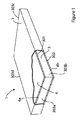
(a)上面、下面及び側部を有する多孔性断熱コアと、
(b)前記断熱コアを被包し、印加された真空を内部に維持するように、前記断熱コアの周りに配置されたエンベロープと、
(c)前記エンベロープと前記断熱コアとの間に4μm〜50μmの厚さを有し、前記断熱コアの前記上面又は下面の実質的に全面に亘って延在する少なくとも1つの金属箔とからなり、
前記金属箔が、前記断熱コアの前記側部の周りに延在せず、
前記金属箔が、前記断熱コアの前記上面と下面との間に熱橋を形成せず、
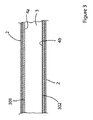
前記エンベロープがエンベロープ内層を有し、前記金属箔がそれにくっつけられた少なくとも1つの熱可塑性外層を有し、前記エンベロープ内層と前記金属箔上の前記外層とが互いにくっついており、任意により互いに接着されている真空断熱パネル(VIP)が提供される。
According to the present invention, in one aspect,
(A) a porous heat insulating core having an upper surface, a lower surface and side portions;
(B) an envelope disposed around the insulating core so as to encapsulate the insulating core and maintain an applied vacuum therein;
(C) comprising at least one metal foil having a thickness of 4 μm to 50 μm between the envelope and the heat insulating core and extending over substantially the entire upper surface or lower surface of the heat insulating core. ,
The metal foil does not extend around the side of the insulating core;
The metal foil does not form a thermal bridge between the upper surface and the lower surface of the heat insulating core,
The envelope has an inner envelope layer, the metal foil has at least one thermoplastic outer layer attached thereto, and the inner envelope layer and the outer layer on the metal foil are adhered to each other and optionally adhered to each other. A vacuum insulation panel (VIP) is provided.
前記金属箔は、エンベロープの透過率を改善する。これは、空気の経年的なエンベロープ内への侵入が相当改善され、その結果、VIPの経年熱伝導率が改善されることを意味している。印加された真空は、長期間に亘って保持される。経年的な真空の保持は、熱伝導率の観点からVIPの性能が長期間保持されることを意味している。これは、VIPの実効寿命が改善されることを意味している。 The metal foil improves the transmittance of the envelope. This means that the penetration of air into the envelope over time is considerably improved, and as a result, the aging thermal conductivity of the VIP is improved. The applied vacuum is maintained for a long time. The maintenance of the vacuum over time means that the performance of the VIP is maintained for a long time from the viewpoint of thermal conductivity. This means that the effective life of the VIP is improved.
特に、本発明によれば、透過率が改善された、コアのエンベロープが提供される。この面において、透過の改善とは、エンベロープ内の真空を保持するという観点から、透過は低ければ低いほど良いので、実際は透過の減少である。経年的にエンベロープ内への(を通しての)空気の透過減少によって、VIPの性能が改善される。 In particular, the present invention provides a core envelope with improved transmission. In this respect, the improvement in transmission is actually a reduction in transmission because the lower the transmission, the better from the viewpoint of maintaining a vacuum in the envelope. Reduced air permeation into and through the envelope over time improves VIP performance.
少なくとも4μmの厚さを有する前記金属箔は、エンベロープを構成するために一般に使用されている材料よりも、大きい熱伝導率を有するであろう。そのため、本発明の真空断熱パネルは、断熱コアをバイパスすることにより熱が断熱コアを通過して伝達されることを可能にする熱橋が前記金属箔によって形成されないように、構成することが重要である。前記金属箔が、上面を越えて(真空断熱パネルの側部を回って)下面に向けて(又はその逆に)延長するようになった場合、熱橋を形成する可能性が増加し、その結果、熱伝導率の点で性能が損なわれる。断熱の観点から、真空断熱パネルの熱伝導率が低ければ低いほど良い。 The metal foil having a thickness of at least 4 μm will have a higher thermal conductivity than the materials commonly used to construct the envelope. Therefore, it is important that the vacuum heat insulation panel of the present invention is configured such that the metal foil does not form a thermal bridge that allows heat to pass through the heat insulation core by bypassing the heat insulation core. It is. If the metal foil extends beyond the top surface (around the side of the vacuum insulation panel) toward the bottom surface (or vice versa), the possibility of forming a thermal bridge increases, As a result, performance is impaired in terms of thermal conductivity. From the viewpoint of heat insulation, the lower the thermal conductivity of the vacuum heat insulation panel, the better.
前記コアは、上面、下面及び側部からなる平行六面体の形状を有する。前記上面及び下面は、前記側部よりも大きな表面積を有する。前記上面及び下面は、完全に対向した面である。前記金属箔は、前記コアに直接接している。前記コアは、通気性のカバー又はスリーブ内に入れることができ、当業者であれば、そのような場合、前記金属箔は、前記コアを入れるスリーブに直接接することが分かる。前記金属箔は、前記エンベロープの層の間に挟み込まれるのではない。特に、前記金属箔は、前記エンベロープの、前記コアの周りに熱橋を形成する層の間に挟み込まれるのではない。 The core has a parallelepiped shape including an upper surface, a lower surface, and side portions. The upper and lower surfaces have a larger surface area than the side portions. The upper surface and the lower surface are completely opposed surfaces. The metal foil is in direct contact with the core. The core can be placed in a breathable cover or sleeve, and those skilled in the art will recognize that in such cases, the metal foil is in direct contact with the sleeve containing the core. The metal foil is not sandwiched between the envelope layers. In particular, the metal foil is not sandwiched between layers of the envelope that form a thermal bridge around the core.
前記金属箔の層は、内面及び外面を有する。上述したように、前記金属箔は、前記エンベロープと前記コアとの間に、例えば前記エンベロープと前記コアの上面(又は下面)との間に配置される。前記金属箔自体が内面及び外面を有し、前記金属箔の内面が前記コアに近接しているのに対し、前記金属箔の外面は前記エンベロープの内面に近接している。 The metal foil layer has an inner surface and an outer surface. As described above, the metal foil is disposed between the envelope and the core, for example, between the envelope and the upper surface (or lower surface) of the core. The metal foil itself has an inner surface and an outer surface, and the inner surface of the metal foil is close to the core, whereas the outer surface of the metal foil is close to the inner surface of the envelope.
前記金属箔は、前記上面と下面との間に熱橋を形成しない。特に、前記金属箔により形成される熱橋は無い。例えば、前記金属箔が、前記断熱コアの側部の周りに延長することはない。その代わり、前記金属箔は、前記断熱コアの上面及び/又は下面にのみ配置される。これが、前記断熱コアを横切ることはない。 The metal foil does not form a thermal bridge between the upper surface and the lower surface. In particular, there is no thermal bridge formed by the metal foil. For example, the metal foil does not extend around the sides of the insulating core. Instead, the metal foil is disposed only on the upper and / or lower surface of the heat insulating core. This does not cross the insulating core.
これは、前記金属箔を用いた結果生じる、真空断熱パネルを全体的に見た熱伝導性能の減損が、前記断熱コアをバイパスする熱橋を通して熱が伝達される熱エッジ効果によって更に妥協を余儀なくされることを意味している。 This is due to the thermal edge effect that results from the use of the metal foil and that the overall heat transfer performance of the vacuum insulation panel as a whole is transferred through a thermal bridge that bypasses the insulation core. Is meant to be.
このように、本願発明者らは、前記断熱コア又はエンベロープよりも熱伝導率特性が劣る金属箔を使用しているにも拘わらず、真空断熱パネルの全体の経年熱性能を改善する構成が可能であることを見出した。 In this way, the inventors of the present application can be configured to improve the overall aging performance of the vacuum insulation panel despite using a metal foil having a thermal conductivity characteristic inferior to that of the insulation core or envelope. I found out.
特に、高熱伝導率の材料は一般に熱伝導性能を劣化させると考えられているので、一般にVIPに使用することは適していないと考えられる熱伝導率を有する金属箔の使用にも拘わらず、本願発明者らは、経年熱性能が改善されるという範囲で、前記エンベロープの通気性を小さくできることを発見した。 In particular, since materials with high thermal conductivity are generally considered to deteriorate the thermal conductivity performance, the present application is not limited to the use of a metal foil having a thermal conductivity that is generally considered unsuitable for use in VIP. The inventors have found that the air permeability of the envelope can be reduced as long as the aging heat performance is improved.
この通気性の減少及びその結果である経年熱性能の改善は、前記コアを囲むエンベロープを有すること、及び前記コアの上面及び/又は下面にのみ存在する金属箔を有することによって達成される。 This reduction in breathability and consequent improvement in aging performance is achieved by having an envelope surrounding the core and having a metal foil present only on the top and / or bottom surface of the core.
前記金属箔は、前記エンベロープの内側にくっつけられる。典型的には、これは真空を印加した後に行われる。前記金属箔は、真空が印加された後でVIPが形成された後に、前記エンベロープの内側に接着することができる。 The metal foil is attached to the inside of the envelope. This is typically done after applying a vacuum. The metal foil can be adhered to the inside of the envelope after the VIP is formed after the vacuum is applied.
本発明の真空断熱パネルにおいて、前記エンベロープは内層を備え、前記金属箔はそれにくっつけられた少なくとも1つの外層を有し、前記エンベロープの内層と前記金属箔の外層とが互いにくっつけられ、任意により互いに接着されている。この記述において、内側は前記真空断熱パネルパネルの構成、特に前記コアに関してのものである。従って、前記エンベロープの内層は、前記断熱コアに向けて内方を向いた側(例えば、前記エンベロープの側)にあり、外層は、前記断熱コアから離れて外方を向いた側(例えば、前記金属箔の側)にある。 In the vacuum heat insulating panel of the present invention, the envelope includes an inner layer, the metal foil has at least one outer layer attached thereto, and the inner layer of the envelope and the outer layer of the metal foil are attached to each other, and optionally, each other. It is glued. In this description, the inside refers to the configuration of the vacuum insulation panel, particularly the core. Therefore, the inner layer of the envelope is on the side facing inward toward the heat insulating core (for example, the side of the envelope), and the outer layer is the side facing away from the heat insulating core (for example, the side of the envelope) On the metal foil side).
上記から分かるように、透過を最小にするためには、エンベロープ全体に亘って透過バリアを有することが望ましい。前記透過バリアが前記コア全体を囲んでいることが望ましい。 As can be seen from the above, it is desirable to have a transmission barrier across the entire envelope to minimize transmission. Desirably, the permeation barrier surrounds the entire core.
この点において、既に市場に出ているVIPは、耐透過性を有するように構成されている。例えば、VIPが、1つ又は複数のメタライズド層で被覆されたポリマーフィルムから形成されたメタライズドフィルムから構成されたエンベロープを有することが一般的である。例えば、メタライズドPET(メタライズド・ポリエチレンテレフタレート)を用いてエンベロープが構成されている。これらの場合、金属堆積技術を用いて所望のフィルム上に金属を被着させ、一般にナノメートル単位(厚さ)の層がメタライズされる。例えば、このようなメタライズド層は、約10〜30nm、例えば約18nm(厚さ)にすることができる。前記メタライズドフィルム(一般に1つ又は複数のメタライズド層で被覆したポリマーフィルムからなる)は、多くの場合、厚さが約5〜20μm、例えば約12μmの厚さである。(これは、前記ポリマーフィルムとメタライズド層とを1つにした厚さである。)多くの場合、使用される金属はアルミニウムである。 In this regard, VIPs already on the market are configured to have permeation resistance. For example, it is common for a VIP to have an envelope composed of a metallized film formed from a polymer film coated with one or more metallized layers. For example, the envelope is made of metallized PET (metallized polyethylene terephthalate). In these cases, metal deposition techniques are used to deposit metal onto the desired film, and typically nanometer (thickness) layers are metallized. For example, such a metallized layer can be about 10-30 nm, for example about 18 nm (thickness). The metallized film (generally composed of a polymer film coated with one or more metallized layers) often has a thickness of about 5-20 μm, for example about 12 μm. (This is the combined thickness of the polymer film and the metallized layer.) In many cases, the metal used is aluminum.
上述したように、メタライズドフィルム例えばメタライズドPETを用いて、VIPのエンベロープを形成することができる。メタライズドPETフィルムは、少なくとも1つの薄い金属層(即ち、メタライズド層)で被覆したポリエチレンテレフタレートのフィルムからなる。VIPを作成するために、各層が上述したタイプのPETメタライズドフィルムのようなメタライズドフィルムである複数の層を用いて、前記エンベロープを作成することができる。そのような場合、前記メタライズドフィルムは、積層体として形成される。前記メタライズド層は、例えばポリエチレン(PE)からなるエンベロープ内層にくっつけることができる。他の適当なエンベロープ内層には、例えば線形低密度ポリエチレン(LLDPE)である低密度ポリエチレン(LDPE)と、超高分子量ポリエチレン(UHMWPE);ポリプロピレン及びエチレンビニルアルコール(EVOH)、ポリ塩化ビニリデン(PVDC);熱可塑性ウレタン;それらの共重合体及び混合物を含むそれらの組合せが含まれる。 As described above, a VIP envelope can be formed using a metallized film such as metallized PET. A metallized PET film consists of a film of polyethylene terephthalate coated with at least one thin metal layer (ie a metallized layer). To create a VIP, the envelope can be created using multiple layers, each layer being a metallized film, such as a PET metallized film of the type described above. In such a case, the metallized film is formed as a laminate. The metallized layer can be attached to an inner envelope layer made of polyethylene (PE), for example. Other suitable envelope inner layers include, for example, low density polyethylene (LDPE), which is linear low density polyethylene (LLDPE), ultra high molecular weight polyethylene (UHMWPE); polypropylene and ethylene vinyl alcohol (EVOH), polyvinylidene chloride (PVDC) Thermoplastic urethanes; copolymers thereof and combinations thereof including mixtures.
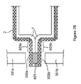
いずれにしても、前記エンベロープを形成する材料は前記コアの周りを包み、次に前記エンベロープがそれ自体にシールされる。これは、前記エンベロープのエッジの周りへの熱の印加によって、例えばエンベロープ材料の2つのエッジを加熱ジョーの間で掴み、次に圧力をかけて加熱して、前記材料をシールして1つのエンベロープにすることによって行うことができる。次に真空を印加し、前記真空が印加されたエンベロープの位置を最終的にまたシールして、真空を保持するエンベロープを形成する。 In any event, the material forming the envelope wraps around the core and then the envelope is sealed to itself. This is due to the application of heat around the edges of the envelope, e.g. grabbing two edges of the envelope material between the heated jaws and then heating under pressure to seal the material to one envelope. Can be done by A vacuum is then applied, and the envelope location where the vacuum is applied is finally sealed again to form an envelope that holds the vacuum.
このようにエンベロープを構成したとき、材料をそれ自体に折り曲げてそれをエッジの周りに熱シールすることにより、エンベロープの全体に亘って同じ材料が使用される。特に、1つ又は複数のメタライズド層で構成したエンベロープの場合、メタライズとフィルムが前記エンベロープの内面全面に亘って延在する。特にこれは、上面に亘って、下面に亘って、かつ側部に亘って延在し、従って前記上面と下面とを橋渡しする。 When constructed in this way, the same material is used throughout the envelope by folding the material into itself and heat sealing it around the edges. In particular, in the case of an envelope composed of one or more metallized layers, the metallization and film extend over the entire inner surface of the envelope. In particular, it extends over the upper surface, over the lower surface and over the sides, thus bridging the upper and lower surfaces.
本発明の金属箔層は、このようなエンベロープ構造と結合して使用することができる。しかしながら、上述したように本発明の金属箔層は、断熱コアの側部の周りに延長せず、前記断熱コアの上面と下面とを橋渡ししない。このような本発明による構造を実現することは、以下に説明する本発明の方法を用いて達成することができる。 The metal foil layer of the present invention can be used in combination with such an envelope structure. However, as described above, the metal foil layer of the present invention does not extend around the sides of the heat insulating core and does not bridge the upper surface and the lower surface of the heat insulating core. Realizing such a structure according to the present invention can be achieved by using the method of the present invention described below.
上述した構成において、前記エンベロープの内面と前記金属箔の外面とは、互いに近接させて配置される。前記エンベロープの内面と前記金属箔は、最初別個に提供し、後で1つにすることかできる。一般に、前記金属箔の外層は、該金属箔の上面及び/又は下面の実質的に全面に亘って設けられる。前記金属箔は、表面積において実質的に前記コアの上面及び/又は下面に対応しているので、これは、前記金属箔が、前記エンベロープの内側に、かつ前記コアの上面及び/又は下面と実質的に整合する位置に保持されることを意味している。前記金属箔は、前記コアの上面及び/又は下面から側部の周りに延長しない。 In the configuration described above, the inner surface of the envelope and the outer surface of the metal foil are disposed close to each other. The inner surface of the envelope and the metal foil can be initially provided separately and later can be combined. Generally, the outer layer of the metal foil is provided over substantially the entire upper surface and / or lower surface of the metal foil. Since the metal foil substantially corresponds in surface area to the top and / or bottom surface of the core, this means that the metal foil is substantially inside the envelope and with the top and / or bottom surface of the core. It means that it is held at a position that is consistently aligned. The metal foil does not extend around the sides from the top and / or bottom surface of the core.
前記少なくとも1つの金属箔が圧延金属であることが望ましい。前記金属箔は、単独で取扱い可能になる。前記金属箔は自立しており、支持部の上に設ける必要が無い。しかしながら、便利良くするために、特にエンベロープに容易にくっつけられるように、前記金属箔上に層を設け、例えば少なくともその外面に層を設ける。この層は、前記エンベロープの層と、これら2つの層を後で例えば加熱によって結合できるようにするために、適合性を有するものである。任意であるが、前記金属箔の外面に設けられる前記層は、ポリマー層である。 Desirably, the at least one metal foil is a rolled metal. The metal foil can be handled alone. The metal foil is self-supporting and need not be provided on the support portion. However, for the sake of convenience, a layer is provided on the metal foil, for example at least on its outer surface, in particular so that it can be easily attached to the envelope. This layer is compatible so that the envelope layer and these two layers can later be combined, for example by heating. Optionally, the layer provided on the outer surface of the metal foil is a polymer layer.
前記エンベロープを形成する材料は、エンベロープを形成するために、エッジでシールされるが、このエッジでのシール形成が、前記金属箔を前記エンベロープに結合しないことは、前記金属箔が前記エンベロープの側部の周りに延在しないので、理解されるであろう。その代わり、前記金属箔は、以下に詳細に説明するように、後の製造工程で前記エンベロープにくっつけられる。 The material forming the envelope is sealed at the edge to form the envelope, but the seal formation at this edge does not bond the metal foil to the envelope so that the metal foil is on the side of the envelope. It will be understood as it does not extend around the part. Instead, the metal foil is attached to the envelope in a later manufacturing process, as will be described in detail below.
前記金属箔は、適当な金属及びその、合金等の組合せで形成することができる。適当な金属には、アルミニウム及び例えばステンレス鋼である鋼鉄が含まれる。 The metal foil can be formed of a combination of an appropriate metal and its alloy. Suitable metals include aluminum and steel, for example stainless steel.
望ましくは、前記少なくとも1つの金属箔の厚さは、4μm〜50μm、又は4μm〜30μm、又は4μm〜20μm、又は4μm〜18μm、又は4μm〜16μm、又は4μm〜14μm、又は4μm〜12μm、又は6μm〜20μm、又は6μm〜18μm、又は6μm〜16μm、又は6μm〜14μm、又は6μm〜12μm、又は8μm〜20μm、又は8μm〜18μm、又は8μm〜16μm、又は8μm〜14μm、又は8μm〜14μm、又は8μm〜12μmである。 Preferably, the thickness of the at least one metal foil is 4 μm to 50 μm, or 4 μm to 30 μm, or 4 μm to 20 μm, or 4 μm to 18 μm, or 4 μm to 16 μm, or 4 μm to 14 μm, or 4 μm to 12 μm, or 6 μm. -20 μm, or 6 μm to 18 μm, or 6 μm to 16 μm, or 6 μm to 14 μm, or 6 μm to 12 μm, or 8 μm to 20 μm, or 8 μm to 18 μm, or 8 μm to 16 μm, or 8 μm to 14 μm, or 8 μm to 14 μm, or 8 μm ~ 12 μm.
本発明の範囲内において、前記少なくとも1つの金属箔は、圧延アルミニウム、例えば厚さ約12μmの圧延アルミニウムとすることができる。 Within the scope of the present invention, the at least one metal foil may be rolled aluminum, for example rolled aluminum having a thickness of about 12 μm.
望ましくは、本発明の真空断熱パネルは2つの金属箔を有し、一方の前記金属箔が、前記断熱コアの上面の略全面に亘って延在し、他方の前記金属箔が、前記断熱コアの下面の略全面に亘って延在する。 Desirably, the vacuum heat insulation panel of the present invention has two metal foils, one of the metal foils extends over substantially the entire upper surface of the heat insulation core, and the other metal foil is the heat insulation core. It extends over substantially the entire lower surface of the.
前記コアの上面又は下面の少なくとも80%に亘って、例えば少なくとも85%、例えば少なくとも90%、例えば少なくとも95%に亘って、金属箔が延在することが望ましい。 Desirably, the metal foil extends over at least 80% of the upper or lower surface of the core, for example over at least 85%, such as at least 90%, such as at least 95%.
本発明の範囲内において、前記エンベロープの内層は、ヒートシールされるべく十分に軟化する熱可塑性材料からなる。この軟化は、前記エンベロープの一体性・完全な状態を危うくする温度より低い温度で発生する。 Within the scope of the present invention, the inner layer of the envelope consists of a thermoplastic material that softens sufficiently to be heat sealed. This softening occurs at a temperature below that which compromises the integrity and integrity of the envelope.
前記熱可塑性材料は、例えば線形低密度ポリエチレン(LLDPE)である低密度ポリエチレン(LDPE)と、超高分子量ポリエチレン(UHMWPE)を含むポリエチレン;ポリプロピレン及びエチレンビニルアルコール(EVOH)、ポリ塩化ビニリデン(PVDC);熱可塑性ウレタン;それらの共重合体及び混合物を含むそれらの組合せからなる群から選択することができる。 The thermoplastic material includes, for example, low density polyethylene (LDPE), which is linear low density polyethylene (LLDPE), and polyethylene including ultra high molecular weight polyethylene (UHMWPE); polypropylene and ethylene vinyl alcohol (EVOH), polyvinylidene chloride (PVDC) Thermoplastic urethane; can be selected from the group consisting of combinations thereof including copolymers and mixtures thereof;
あらゆる適当なグレードの材料を用いることができる。これらには、可塑性化のグレード(plasticised
grade)、難燃性のグレード(flame retardant grade)及びそれらの組合せが含まれる。
Any suitable grade of material can be used. These include plasticized grades (plasticised
grade), flame retardant grade and combinations thereof.
前記金属箔上に外層が設けられる場合、前記外層は、ポリエチレン、ポリプロピレン及びエチレンビニルアルコール又はそれらの共重合体からなる群から選択される熱可塑性ポリマーからなる。 When an outer layer is provided on the metal foil, the outer layer is made of a thermoplastic polymer selected from the group consisting of polyethylene, polypropylene, ethylene vinyl alcohol, or a copolymer thereof.
前記金属箔上に外層が設けられ、前記エンベロープ上に内層が設けられ、前記金属箔の外層と前記エンベロープの内層とは、前記真空断熱パネルを加熱することによって接着される。 An outer layer is provided on the metal foil, an inner layer is provided on the envelope, and the outer layer of the metal foil and the inner layer of the envelope are bonded by heating the vacuum heat insulating panel.
前記金属箔が、実質的にその全表面積に亘って前記エンベロープの内側にくっつけられることが望ましい。例えば、前記エンベロープと前記金属箔とは、くっつけたとき、実際上積層構造を形成することができる。前記金属箔が、前記積層構造の最内層を形成する。当業者であれば、前記金属箔が前記コアに近接していることが理解されるであろう。前記金属箔が、前記コアの周りに熱橋を形成するプラスチック層の間に挟み込まれていない。 Desirably, the metal foil is attached to the inside of the envelope over substantially its entire surface area. For example, the envelope and the metal foil can actually form a laminated structure when bonded together. The metal foil forms the innermost layer of the laminated structure. One skilled in the art will appreciate that the metal foil is in close proximity to the core. The metal foil is not sandwiched between plastic layers that form a thermal bridge around the core.
前記エンベロープの内層は、ポリエチレンフィルムのようなポリエチレン材料から構成し、前記金属箔の外層は、ポリエチレンコーティングのようなポリエチレン材料から構成することができる。 The inner layer of the envelope may be composed of a polyethylene material such as a polyethylene film, and the outer layer of the metal foil may be composed of a polyethylene material such as a polyethylene coating.
前記金属箔にくっつく前記エンベロープの内層は、その厚さを約10μmから約50μmの範囲にすることができる。前記エンベロープにくっつく前記金属箔の外層は、その厚さを約10μmから約50μmの範囲にすることができる。 The inner layer of the envelope that adheres to the metal foil can have a thickness in the range of about 10 μm to about 50 μm. The outer layer of the metal foil that sticks to the envelope can have a thickness in the range of about 10 μm to about 50 μm.
上述したように、前記金属箔には層がくっつけられ、前記層は、前記金属箔の外面にくっつけられる。前記層は、一般にポリマー層である。前記層は、接着剤の使用を含むあらゆる所望の方法によって、前記金属箔にくっつけられる。前記金属箔にくっつけられる前記層は、例えばポリエチレン(PE)とすることができる。その場合、前記金属箔は、積層構造の一部を形成することができる。積層構造であるか否かに拘わらず、真空が印加される後まで、前記金属箔は、前記エンベロープの内面に直接(又は間接に)くっけられることはない。任意で、前記金属箔の内面に層をくっつけることができる。この層は、一般にポリマー層、任意で熱可塑性ポリマー層であり、前記層は、接着剤の使用を含むあらゆる所望の方法によって前記金属箔にくっつけることができる。この前記金属箔の内層は、前記コアの側部の周りに延長していない。例えば、前記金属箔の内層によって、前記コアの上面と前記コアの下面との間に、熱橋は形成されない。前記内層は、前記金属箔と実質的に同じサイズにすることができ、好適には、前記金属箔の内層は該金属箔と同じサイズである。 As described above, a layer is attached to the metal foil, and the layer is attached to the outer surface of the metal foil. The layer is generally a polymer layer. The layer is attached to the metal foil by any desired method including the use of an adhesive. The layer attached to the metal foil can be, for example, polyethylene (PE). In that case, the said metal foil can form a part of laminated structure. Regardless of whether it is a laminated structure, the metal foil is not directly (or indirectly) attached to the inner surface of the envelope until after a vacuum is applied. Optionally, a layer can be attached to the inner surface of the metal foil. This layer is generally a polymer layer, optionally a thermoplastic polymer layer, which can be attached to the metal foil by any desired method, including the use of adhesives. The inner layer of the metal foil does not extend around the side of the core. For example, a thermal bridge is not formed between the upper surface of the core and the lower surface of the core by the inner layer of the metal foil. The inner layer can be substantially the same size as the metal foil, and preferably the inner layer of the metal foil is the same size as the metal foil.
前記エンベロープはメタライズドフィルムを有することができ、例えば前記エンベロープは、複数のメタライズドフィルムを有することができる。例えば前記エンベロープは、積層構造の複数のメタライズドフィルムを有することができる。例えば、3つのメタライズドフィルムを積層構造内に設けることができる。このような構成では、前記フィルムのメタライズされた側が、一般に外側(前記エンベロープの外面に向けて)を向くことになる。 The envelope may have a metallized film, for example, the envelope may have a plurality of metallized films. For example, the envelope may have a plurality of metallized films having a laminated structure. For example, three metallized films can be provided in the laminated structure. In such a configuration, the metallized side of the film will generally face outward (toward the outer surface of the envelope).
前記エンベロープの内層として、別の層を設けることができる。このような層は、典型的には、非メタライズド層となる。上述したように、この別の層は、ポリエチレン層とすることができる。再び、前記エンベロープの全体構造を積層体として設けることができ、この場合、前記エンベロープはその積層体から作成される。前記エンベロープは、エッジのシール処理によってシールされる。しかしながら、前記金属箔、又は前記金属箔が組み込まれたあらゆる積層体は、前記エッジのシール処理によって前記エンベロープにくっつけられない。 Another layer may be provided as the inner layer of the envelope. Such a layer is typically a non-metallized layer. As mentioned above, this further layer can be a polyethylene layer. Again, the entire structure of the envelope can be provided as a stack, in which case the envelope is made from the stack. The envelope is sealed by an edge sealing process. However, the metal foil or any laminate incorporating the metal foil is not attached to the envelope by the edge sealing process.
前記メタライズドフィルム内で前記金属層を支持する材料は、一般にポリマー材料である。これは、前記エンベロープの内層より高い融点を有するように選択される。例えば、前記エンベロープは、複数のメタライズドPETからなる層で構成することができ、その場合、前記エンベロープの内層はPEから形成することができる。 The material that supports the metal layer in the metallized film is generally a polymer material. This is selected to have a higher melting point than the inner layer of the envelope. For example, the envelope can be composed of a layer made of a plurality of metallized PET, and in this case, the inner layer of the envelope can be made of PE.
一般に、PETは、ポリエチレンより高い融点を有する。例えば、PETは、250℃より高い融点を持つことができる。ポリエチレンは、一般に融点が約105〜180℃の範囲内である。例えば、低密度ポリエチレンは、約105〜115℃の範囲内の融点を持つことができる。例えば、中程度から高い密度のポリエチレンは、115〜180℃の範囲内の融点を持つことができる。 In general, PET has a higher melting point than polyethylene. For example, PET can have a melting point higher than 250 ° C. Polyethylene generally has a melting point in the range of about 105-180 ° C. For example, the low density polyethylene can have a melting point in the range of about 105-115 ° C. For example, medium to high density polyethylene can have a melting point in the range of 115-180 ° C.
本発明の真空断熱パネルは、約1.5mW/m.Kから約6.5mW/m.K、例えば約1.5mW/m.Kから約4.5mW/m.Kの熱伝導率を有することができる。好ましくは、本発明のVIPは、約4.5mW/m.K又はそれより小さい熱伝導率値を有する。 The vacuum insulation panel of the present invention has a thermal conductivity of about 1.5 mW / m.K to about 6.5 mW / m.K, such as about 1.5 mW / m.K to about 4.5 mW / m.K. be able to. Preferably, the VIP of the present invention has a thermal conductivity value of about 4.5 mW / m.K or less.
一般的なメタライズドフィルムは、規格ASTM D3985に従って測定(23℃、相対湿度50%で測定)して、約2x10⁻³cc/m2.dayより低い酸素透過率(OTR)を有し、規格ASTM F1249−90(38℃、相対湿度100%で測定)して、約0.02g/m2.dayの水蒸気透過率を有する。対照的に、一般的なアルミニウム箔は、規格ASTM D3985に従って測定(23℃、相対湿度50%で測定)して、約5x10⁻⁴cc/m2.dayより低い酸素透過率(OTR)を有し、規格ASTM F1249−90(38℃、相対湿度100%で測定)して、約0.005g/m2.dayより低い水蒸気透過率を有する。前述の値は、平坦なフィルムサンプルについて測定したものであり、該平坦なフィルムサンプルは、VIPのエンベロープに認められるようなシールを備えていない。 A typical metallized film has an oxygen transmission rate (OTR) of less than about 2 × 10 −3 cc / m 2 .day, measured according to standard ASTM D3985 (measured at 23 ° C. and 50% relative humidity), and is standard ASTM F1249-90 (measured at 38 ° C. and 100% relative humidity) has a water vapor transmission rate of about 0.02 g / m 2 .day. In contrast, common aluminum foil has an oxygen transmission rate (OTR) of less than about 5 × 10 −4 cc / m 2 .day, measured according to standard ASTM D3985 (measured at 23 ° C. and 50% relative humidity). Standard ASTM F1249-90 (measured at 38 ° C. and 100% relative humidity) has a water vapor transmission rate lower than about 0.005 g / m 2 .day. The above values were measured on a flat film sample, which does not have a seal as found in the VIP envelope.
VIPのエンベロープにおいて、エンベロープのバリア材料内の欠陥及びエンベロープのシールの存在は、エンベロープの透過値を、上述した標準的な試験方法に従って使用されるような平坦なフィルムサンプルについて測定した透過値よりも、高くする。従って、エンベロープを通過する透過は、メタライズされたバリアを有しないエンベロープのシールを通過する透過のために、一般に高い。従来のVIPのエンベロープにおける全体の酸素透過率は、メタライズされていないシールの存在のために、平坦なフィルムのそれよりも十倍以上高くなる。即ち、従来のメタライズドフィルムを有するVIPのエンベロープにおける酸素透過率は、約20x10−3cc/m2.dayである。 In a VIP envelope, the presence of defects in the envelope barrier material and the presence of the envelope seal is such that the envelope transmission value is greater than the transmission value measured for a flat film sample as used in accordance with the standard test method described above. , Make it high. Thus, the transmission through the envelope is generally high due to the transmission through the envelope seal without the metallized barrier. The overall oxygen transmission rate in a conventional VIP envelope is more than ten times higher than that of a flat film due to the presence of a non-metallized seal. That is, the oxygen permeability in the envelope of a VIP having a conventional metallized film is about 20 × 10 −3 cc / m 2 .day.
メタライズドフィルム(例えば、メタライズドPET)で作られたVIPのエンベロープのOTRが約20x10−3cc/m2.dayであるのに対し、アルミニウム箔でVIPのエンベロープのOTRは、約5x10−3cc/m2.dayである
本発明によれば、
(a)上面、下面及び側部を有する多孔性断熱コアと、
(b)前記断熱コアを被包し、印加された真空を内部に維持するように、前記断熱コアの周りに配置されたエンベロープと、
前記エンベロープと前記断熱コアとの間に4μm〜50μmの厚さを有し、前記断熱コアの前記上面又は下面の実質的に全面に亘って延在する少なくとも1つの金属箔とからなり、
前記金属箔が、前記断熱コアの前記側部の周りに延在せず、
前記金属箔が、前記断熱コアの前記上面と下面との間に熱橋を形成せず、
前記エンベロープがエンベロープ内層を有し、前記金属箔がそれにくっつけられた少なくとも1つの熱可塑性外層を有し、前記エンベロープ内層と前記金属箔上の前記外層とが互いにくっついている真空断熱パネルが提供される。
The VIP envelope OTR made of metallized film (eg, metallized PET) is about 20 × 10 −3 cc / m 2 .day, whereas the VIP envelope OTR with aluminum foil is about 5 × 10 −3 cc / m 2 .day, according to the present invention,
(A) a porous heat insulating core having an upper surface, a lower surface and side portions;
(B) an envelope disposed around the insulating core so as to encapsulate the insulating core and maintain an applied vacuum therein;
And having at least one metal foil having a thickness of 4 μm to 50 μm between the envelope and the heat insulating core and extending over substantially the entire upper surface or lower surface of the heat insulating core,
The metal foil does not extend around the side of the insulating core;
The metal foil does not form a thermal bridge between the upper surface and the lower surface of the heat insulating core,
A vacuum thermal insulation panel is provided in which the envelope has an inner envelope layer, the metal foil has at least one thermoplastic outer layer attached thereto, and the inner envelope layer and the outer layer on the metal foil are adhered to each other. The
好適には、前記エンベロープがメタライズドフィルムを有する。より好適には、前記エンベロープが複数のメタライズドフィルムを有する。真空が印加された後に前記エンベロープの内層にくっつけられる前記金属箔の存在によって、前記エンベロープのバリア性能が実質的に改善され、例えば水蒸気透過率及び酸素透過率が、従来のVIPと比較して実質的に低減される。 Preferably, the envelope has a metallized film. More preferably, the envelope has a plurality of metallized films. Due to the presence of the metal foil that is attached to the inner layer of the envelope after a vacuum is applied, the barrier performance of the envelope is substantially improved, e.g., water vapor transmission rate and oxygen transmission rate are substantially higher than conventional VIP. Reduced.
本発明によるVIPの水蒸気透過率(MVTR)は、約1.5x10⁻³g/m2.dayと約3.0x10−3g/m2.dayの間である。本発明によるVIPのMVTRが約2.5x10−3g/m2.day又はそれ以下であると好ましい。 Water vapor transmission rate of VIP according to the invention (MVTR) is between about 1.5x10 -3 g / m 2 .day and about 3.0x10 -3 g / m 2 .day. The MVTR of the VIP according to the present invention is preferably about 2.5 × 10 −3 g / m 2 .day or less.
本発明によるVIPの酸素透過率(OTR)は、約2x10⁻³cc/m2.dayと約5x10−3cc/m2.dayの間である。本発明によるVIPのOTRが約4x10−3cc/m2.day又はそれ以下であると好ましい。 The oxygen permeability of the VIP according to the invention (OTR) is between about 2x10 -3 cc / m 2 .day and about 5x10 -3 cc / m 2 .day. The VIP OTR according to the present invention is preferably about 4 × 10 −3 cc / m 2 .day or less.
好ましくは、本発明によるVIPが、約2.5x10⁻³g/m2.day又はそれ以下のMVTRと、約4x10−3cc/m2.day又はそれ以下のOTRを有する。これらの効果は、前記金属箔に接着された前記熱可塑性外層により前記エンベロープの内層にくっつけられている前記金属箔の存在によって達成され、強化されたエッジシール処理の効果は、真空を印加した後に前記金属箔が前記エンベロープの内層にくっつけられることの結果として達成される。これらの結合した効果の結果として、従来ののVIPよりも寿命が長くなりかつ熱伝導率を低下させた、改善されたVIPが得られる。 Preferably, a VIP according to the present invention has an MVTR of about 2.5 × 10 −3 g / m 2 .day or less and an OTR of about 4 × 10 −3 cc / m 2 .day or less. These effects are achieved by the presence of the metal foil attached to the inner layer of the envelope by the thermoplastic outer layer bonded to the metal foil, and the enhanced edge seal treatment effect is achieved after applying a vacuum. This is achieved as a result of the metal foil being attached to the inner layer of the envelope. As a result of these combined effects, an improved VIP is obtained that has a longer life than conventional VIP and has reduced thermal conductivity.
好適には、本発明によるVIPは、約4.5mW/m.K又はそれより低い熱伝導率を有する。 Preferably, the VIP according to the present invention has about 4.5 mW / m. It has a thermal conductivity of K or lower.
また、本発明によれば、上面、下面及び側部を有するコアを有する真空断熱パネルのエンベロープであって、
前記エンベロープが内面及び外面を有し、
前記エンベロープが、前記コアの周りに配置されて、前記コアを被包するように配設され、前記エンベロープ内に印加された真空を維持するようになっており、
前記エンベロープの前記内面が前記コアの近位にあり、かつ前記エンベロープの前記外面が前記コアの遠位にあり、
前記エンベロープの前記内面が、例えば、ポリエチレンのような熱可塑性材料の内層を備え、
前記エンベロープが更に、4μm〜50μmの厚さを有する少なくとも1つの金属箔を備え、前記金属箔がそれにくっつけられた熱可塑性外層を有し、前記金属箔が、前記エンベロープの最内面にくっつけられ、前記エンベロープと前記コアとの間にあって、前記コアの前記上面及び/又は下面の実質的に全面に亘って延在するように配置されており、前記金属箔が断熱性の前記コアの前記側部の周りに延在せず、前記金属箔が前記コアの前記上面と下面との間に熱橋を形成しない、真空断熱パネルのエンベロープが提供される。
Moreover, according to the present invention, an envelope of a vacuum heat insulation panel having a core having an upper surface, a lower surface and side portions,
The envelope has an inner surface and an outer surface;
The envelope is disposed around the core and is disposed to encapsulate the core to maintain a vacuum applied within the envelope;
The inner surface of the envelope is proximal to the core and the outer surface of the envelope is distal to the core;
The inner surface of the envelope comprises an inner layer of a thermoplastic material such as, for example, polyethylene;
The envelope further comprises at least one metal foil having a thickness of 4 μm to 50 μm, the metal foil having a thermoplastic outer layer attached thereto, the metal foil being attached to the innermost surface of the envelope; The side portion of the core that is between the envelope and the core and is disposed so as to extend over substantially the entire upper surface and / or lower surface of the core, and wherein the metal foil is thermally insulated. An envelope of a vacuum insulation panel is provided that does not extend around and the metal foil does not form a thermal bridge between the upper and lower surfaces of the core.
前記少なくとも1つの金属箔は、前記金属箔と前記エンベロープの内層との間に形成された接着部によって、前記エンベロープの内層にくっつけることができる。 The at least one metal foil may be attached to the inner layer of the envelope by an adhesive portion formed between the metal foil and the inner layer of the envelope.
或る実施形態で2つの金属箔がある場合には、1つの金属箔が、前記コアの上面の実質的に全面に亘って延在するように、前記エンベロープと前記金属箔との間に配置することができ、1つの金属箔が、前記コアの下面の実質的に全面に亘って延在するように、前記エンベロープと前記金属箔との間に配置することができる。 In some embodiments, where there are two metal foils, one metal foil is disposed between the envelope and the metal foil so that it extends over substantially the entire top surface of the core. And a single metal foil can be disposed between the envelope and the metal foil such that it extends over substantially the entire lower surface of the core.
本発明のエンベロープでは、前記少なくとも1つの金属箔は、上述したように最終製品のVIPにおいて、前記金属箔が前記コアの上面と下面との間に熱橋を形成しないように、前記エンベロープの別々の領域に配置される。前記金属箔は、前記エンベロープの内面にくっつけられ、VIPの前記コアの側部を回り込まないように、実質的に前記コアの上面及び/又は下面上に位置するように配置される。この構成によって、前記金属箔が前記コアの上面と前記コアの下面との間に熱橋を形成しないことが確保される。 In the envelope of the present invention, the at least one metal foil is separated from the envelope so that the metal foil does not form a thermal bridge between the upper surface and the lower surface of the core in the VIP of the final product as described above. It is arranged in the area. The metal foil is attached to the inner surface of the envelope and is disposed so as to be substantially located on the upper surface and / or the lower surface of the core so as not to wrap around the side portion of the core of the VIP. This configuration ensures that the metal foil does not form a thermal bridge between the upper surface of the core and the lower surface of the core.
前記金属箔を前記エンベロープの内面にくっつけることによって、本発明の前記エンベロープにおける透過が、従来のVIPのエンベロープにおける透過よりも相当低くなるので、結果物として得られるVIPの経年熱性能が改善される。 By attaching the metal foil to the inner surface of the envelope, the permeation in the envelope of the present invention is considerably lower than the permeation in the conventional VIP envelope, thus improving the aging performance of the resulting VIP. .
また、本発明によれば、上述したエンベロープの真空断熱パネルにおける使用が提供される。 Moreover, according to this invention, use in the vacuum heat insulation panel of the envelope mentioned above is provided.
本発明のVIPのエンベロープは、全体的にメタライズドフィルムで作られた従来のVIPと比較して、透過性能が改善されている。上述したように前記エンベロープの内層に接着された前記金属箔の存在により、前記エンベロープにおける透過が大きく減少する。従って、本発明のVIPのエンベロープにかかるOTR及びMVTRが、全体的にメタライズドフィルムで作られた従来のVIPと比較して、大きく減少する。本発明によるVIPのエンベロープは、OTRが約2x10⁻³cc/m2.day〜約5x10−3cc/m2.dayの間である。更に、本発明によるVIPのエンベロープのMVTRは、約1.5x10−3g/m2.day〜約3.0x10−3g/m2.dayの間である。 The VIP envelope of the present invention has improved transmission performance compared to conventional VIP made entirely of metallized film. As described above, the presence of the metal foil adhered to the inner layer of the envelope greatly reduces the transmission through the envelope. Therefore, the OTR and MVTR over the envelope of the VIP of the present invention is greatly reduced compared to a conventional VIP made entirely of metallized film. Envelope VIP according to the invention is between OTR of about 2x10 -3 cc / m 2 .day~ about 5x10 -3 cc / m 2 .day. Furthermore, MVTR of the envelope of the VIP according to the invention is between about 1.5x10 -3 g / m 2 .day~ about 3.0x10 -3 g / m 2 .day.
好ましくは、本発明によるエンベロープのMVTRが約2.5x10⁻³g/m2.day又はそれ以下である。好ましくは、本発明によるエンベロープの酸素透過率(OTR)が約4x10−3cc/m2.day又はそれ以下である。 Preferably, the MVTR of the envelope according to the invention is about 2.5 × 10 −3 g / m 2 .day or less. Preferably, the oxygen transmission rate (OTR) of the envelope according to the present invention is about 4 × 10 −3 cc / m 2 .day or less.
或る実施形態において、本発明のVIPのエンベロープは、約4x10⁻³cc/m2.dayのOTRを有する。別の実施形態において、本発明のVIPのエンベロープは、約2.5x10−3g/m2.dayのMVTRを有する。更に別の実施形態では、本発明のVIPのエンベロープは、約4x10−3cc/m2.dayのOTR及び約2.5x10−3g/m2.dayのMVTRを有する。 In some embodiments, the VIP envelope of the present invention has an OTR of about 4 × 10 −3 cc / m 2 .day. In another embodiment, the envelope of the VIP of the present invention has an MVTR of about 2.5 × 10 −3 g / m 2 .day. In yet another embodiment, the envelope of the VIP of the present invention has an OTR of about 4 × 10 −3 cc / m 2 .day and an MVTR of about 2.5 × 10 −3 g / m 2 .day.
従って、本発明のエンベロープの透過性能は、アルミニウムのエンベロープの透過性能より上、又は同程度である。しかしながら、本発明のエンベロープの熱伝導率が、アルミニウムのエンベロープの熱伝導率よりも、VIPのエッジ付近で大幅に低いので、比較すると熱エッジ効果が減少している。 Accordingly, the transmission performance of the envelope of the present invention is above or similar to the transmission performance of the aluminum envelope. However, since the thermal conductivity of the envelope of the present invention is much lower near the edge of the VIP than that of the aluminum envelope, the thermal edge effect is reduced in comparison.
本発明によれば、
(a)上面、下面及び側部を有する多孔性断熱コアを準備する過程と、
(b)前記断熱コアの前記上面又は下面の実質的に全体に亘って延在する、少なくとも4μmの厚さを有する少なくとも1つの金属箔を、前記金属箔が前記断熱コアの前記上面と下面との間に熱橋を形成しないように準備する過程と、
(c)内面及び外面を有するエンベロープを準備する過程であって、前記エンベロープが、(i)前記金属箔を前記エンベロープと前記断熱コアとの間にして、前記断熱コア及び前記金属箔を被包し、(ii)印加された真空を前記エンベロープ内に維持するように配置される過程と、
(d)前記エンベロープに真空を印加する過程と、
(e)真空が印加された後の前記エンベロープの前記内面に前記金属箔をくっつける過程とからなる真空断熱パネルの製造方法が提供される。
According to the present invention,
(A) preparing a porous insulating core having an upper surface, a lower surface and side portions;
(B) at least one metal foil having a thickness of at least 4 μm extending substantially over the entire upper surface or lower surface of the heat insulating core, wherein the metal foil comprises the upper and lower surfaces of the heat insulating core; The process of preparing not to form a thermal bridge between,
(C) A process of preparing an envelope having an inner surface and an outer surface, wherein the envelope includes (i) encapsulating the heat insulating core and the metal foil with the metal foil interposed between the envelope and the heat insulating core. (Ii) a process arranged to maintain an applied vacuum within the envelope;
(D) applying a vacuum to the envelope;
(E) There is provided a method for manufacturing a vacuum heat insulating panel comprising a step of attaching the metal foil to the inner surface of the envelope after a vacuum is applied.
前記金属箔をくっつける工程が真空を印加した後に完了することによって、前記エンベロープを挟んだ圧力差(真空の印加によってエンベロープ内が減圧されたことにより起こる)が、前記金属箔を前記エンベロープの内部に接合させる非常に強い付勢力を発生させる。この場合、本質的に、大気圧は、前記エンベロープを前記金属箔に対して押し付け、次に前記金属箔を前記コアに対して押し付けるのに十分な強さを有する。この圧力は、別々の2つの部分(前記金属箔と前記エンベロープ)をそれらが接する全領域で結合し得るのに十分な大きさを有する。 When the step of attaching the metal foil is completed after applying a vacuum, a pressure difference across the envelope (which occurs when the inside of the envelope is depressurized by applying a vacuum) causes the metal foil to enter the inside of the envelope. Generates a very strong biasing force to join. In this case, essentially the atmospheric pressure is strong enough to press the envelope against the metal foil and then the metal foil against the core. This pressure is large enough to allow two separate parts (the metal foil and the envelope) to be joined in the entire area where they meet.
前記くっつける工程は、真空を印加するための設備を取り外した後に実行し得ることが分かる。即ち、前記くっつける工程は、前記エンベロープ内に保持される真空が唯一存在する真空であるとき、実行することができる。従って、前記くっつける工程は、VIPが排気されかつ次に、真空を維持するようにシールされた後に、行うことができる。真空が存在するのは、減圧されかつシールされた前記エンベロープ内である。 It can be seen that the attaching step can be performed after the equipment for applying the vacuum is removed. That is, the step of attaching can be performed when the vacuum held in the envelope is the only vacuum that exists. Thus, the attaching step can be performed after the VIP is evacuated and then sealed to maintain a vacuum. A vacuum exists in the envelope that is depressurized and sealed.
前記金属箔は、前記コアの上面又は下面の実質的に全領域に亘って、前記エンベロープの透過率を減少させるように配置される。 The metal foil is arranged to reduce the transmittance of the envelope over substantially the entire area of the upper or lower surface of the core.
前記エンベロープがエンベロープ内層を有し、かつ前記金属箔がそれにくっつけられた少なくとも1つの外層を有する場合、前記エンベロープ内層と前記金属箔の外層とが互いにくっつけられ、任意により互いに接着される。 When the envelope has an inner envelope layer and the metal foil has at least one outer layer attached thereto, the inner envelope layer and the outer layer of the metal foil are attached to each other and optionally adhered to each other.
本明細書中に記載される本発明の真空断熱パネルのいずれの構造も、本発明の方法によって作ることができる。 Any of the inventive vacuum insulation panels described herein can be made by the method of the present invention.
前記エンベロープの内層は、ポリエチレン、ポリプロピレン及びエチレンビニルアルコール又はそれらの共重合体からなる群から選択される重合体から構成することができる。 The inner layer of the envelope can be composed of a polymer selected from the group consisting of polyethylene, polypropylene and ethylene vinyl alcohol or copolymers thereof.
前記金属箔の外層は、ポリエチレン、ポリプロピレン及びエチレンビニルアルコール又はそれらの共重合体からなる群から選択される重合体から構成することができる。 The outer layer of the metal foil can be composed of a polymer selected from the group consisting of polyethylene, polypropylene and ethylene vinyl alcohol or copolymers thereof.
前記金属箔と前記エンベロープの内面とは、前記真空断熱パネルを加熱する(前記真空が印加された後)ことによって、互いにくっつけることができる。好適には、前記真空断熱パネル全体がオーブン内で加熱される。単に真空断熱パネルの上面又は下面を加熱するのに対して、真空断熱パネル全体を加熱することによって、エッジのシールが明確に強化される。 The metal foil and the inner surface of the envelope can be attached to each other by heating the vacuum insulation panel (after the vacuum is applied). Preferably, the entire vacuum insulation panel is heated in an oven. By simply heating the entire vacuum insulation panel as opposed to simply heating the top or bottom surface of the vacuum insulation panel, the edge seal is clearly enhanced.
前記金属箔と前記エンベロープの内面とは、前記真空断熱パネルを約100〜180℃の温度に、任意で約0.5〜10分間加熱することによって、互いにくっつけることができる。 The metal foil and the inner surface of the envelope can be attached to each other by heating the vacuum insulation panel to a temperature of about 100-180 ° C, optionally for about 0.5-10 minutes.
従来のVIPは、おおよそ5.0mW/m.Kの熱伝導率(ラムダ値)を有する。本発明のVIPは、約3.0mW/m.Kから約4.0mW/mK.の熱伝導率を有し、望ましくは、本発明のVIPは、約3.5mW/m.K又はそれより小さい、例えば約3.2mW/m.K又はそれより小さい熱伝導率値を有する。 A conventional VIP has a thermal conductivity (lambda value) of approximately 5.0 mW / m.K. The VIP of the present invention has a thermal conductivity of about 3.0 mW / m.K to about 4.0 mW / mK. Preferably, the VIP of the present invention has a thermal conductivity of about 3.5 mW / m.K or more. It has a thermal conductivity value that is small, for example about 3.2 mW / m.K or less.
本発明のVIPは、熱伝導率が改善され、VIP内に前記少なくとも1つの金属箔がそんざいすることによって、前記バリアエンベロープにおける透過が減少しているので、従来のVIPより長い寿命を有する。 The VIP of the present invention has a longer life than conventional VIP because of improved thermal conductivity and reduced penetration in the barrier envelope due to the presence of the at least one metal foil in the VIP.
更に、本発明のVIPのエンベロープのエッジ付近のシールは、以下に詳細に説明する本発明のVIPの製造方法によって、従来のVIPのエッジ付近のシールよりも実質的に強くかつ大きい。 Further, the seal near the edge of the VIP envelope of the present invention is substantially stronger and larger than the seal near the edge of the conventional VIP due to the method of manufacturing the VIP of the present invention described in detail below.
当業者であれば、真空断熱パネルに適したあらゆる断熱コアを、本発明の真空断熱パネルにおける断熱コアとして使用し得ることが理解される。例えば、前記断熱コアは、ガラスファイバー材料、フォーム材料、特に実質的な連続気泡発泡体、例えば実質的に連続気泡のポリウレタンフォーム、フェノールフォーム、ポリスチレンフォーム、又は混合ポリマーフォームから構成することができる。前記断熱コアは、ガラスファイバー材料から構成することができ、例えば、ガラスファイバーボード又はガラスウールから構成することができる。 One skilled in the art will appreciate that any insulating core suitable for a vacuum insulation panel can be used as the insulation core in the vacuum insulation panel of the present invention. For example, the insulating core can be composed of glass fiber material, foam material, in particular substantially open cell foam, such as substantially open cell polyurethane foam, phenolic foam, polystyrene foam, or mixed polymer foam. The heat insulation core can be made of glass fiber material, for example, glass fiber board or glass wool.
好適には、前記断熱コアは、粒状の形態をなす断熱材料から構成することができる。特に、前記断熱コアは、シリカ、パーライト、珪藻土、並びにヒュームドシリカ及びそれらの組合せ等の微孔質材料から構成することができる。 Suitably, the said heat insulation core can be comprised from the heat insulation material which makes a granular form. In particular, the insulating core can be composed of microporous materials such as silica, pearlite, diatomaceous earth, and fumed silica and combinations thereof.
任意で、前記断熱材料は、直径が約1μmより小さい平均粒径の微孔質断熱材料とすることができる。一般に、微孔質断熱材料は、約20nmから約500nmの平均粒径を有し、例えば約50nmから約500nm、又は約50nmから約400nm、又は約50nmから約350nm、又は約50nmから約300nm、又は約100nmから約300nm、又は約100nmから約400nmである。微孔性断熱材料の平均粒径は、約200nmよりも小さいことが好ましい。 Optionally, the thermal insulation material can be a microporous thermal insulation material having an average particle size of less than about 1 μm in diameter. Generally, the microporous insulation material has an average particle size of about 20 nm to about 500 nm, such as about 50 nm to about 500 nm, or about 50 nm to about 400 nm, or about 50 nm to about 350 nm, or about 50 nm to about 300 nm, Or about 100 nm to about 300 nm, or about 100 nm to about 400 nm. The average particle size of the microporous insulation material is preferably less than about 200 nm.
これらの材料は、カーボンブラック、二酸化チタン、鉄酸化物、マグネタイト若しくは炭化ケイ素、又はそれらの組合せ等の赤外線吸収材料(IR乳白剤)を混合することができる。 These materials can be mixed with an infrared absorbing material (IR opacifier) such as carbon black, titanium dioxide, iron oxide, magnetite or silicon carbide, or combinations thereof.
従って、前記断熱コアの断熱材料が主として微孔性材料から構成されるとは言え、更に繊維バインダー(高分子又は無機材であり得る)及び赤外線乳白剤(例えば、炭化ケイ素、カーボンクラック又は鉄酸化物)が少ない割合(典型的には、それぞれ5〜20%)であってもよい。前記繊維及び乳白剤は、いずれも微孔性である必要が無く、一般に微孔性ではない。 Therefore, although the heat insulating material of the heat insulating core is mainly composed of a microporous material, a fiber binder (which can be a polymer or an inorganic material) and an infrared opacifier (for example, silicon carbide, carbon crack or iron oxidation) The ratio may be small (typically 5 to 20% each). Neither the fiber nor the opacifier needs to be microporous and is generally not microporous.
前記断熱材料は混合物であってもよく、例えば、(一度加圧すると)前記粒状材料を一体に結合させるように働く繊維を含むことができる。前記繊維は、有機又は無機材料であってよい。或る場合に、前記繊維はポリエステル繊維又はポリプロピレン繊維である。 The thermal insulation material may be a mixture and may include, for example, fibers that serve to bond the particulate material together (when pressed once). The fibers may be organic or inorganic materials. In some cases, the fibers are polyester fibers or polypropylene fibers.
好ましくは、前記断熱コアは、断熱材料、例えばフュームドシリカ、沈降シリカ若しくはパーライト、又はそれらの組合せを主成分とする粉末からなる。前記多孔性断熱コアは、断熱(微孔性)コアに形成される粉末材料、例えば、フュームドシリカ、沈降シリカ及びパーライト、又はそれらの組合せからなる群から選択される粉状多孔質断熱材料から構成される。 Preferably, the heat insulating core is made of a heat insulating material such as fumed silica, precipitated silica or pearlite, or a powder based on a combination thereof. The porous heat insulating core is a powder material formed into a heat insulating (microporous) core, for example, a powdery porous heat insulating material selected from the group consisting of fumed silica, precipitated silica and perlite, or a combination thereof. Composed.
前記コアは、該コア及び前記少なくとも1つの金属箔を柔軟なエンベロープに入れる前に、通気性カバー内に入れることができる。 The core can be placed in a breathable cover prior to placing the core and the at least one metal foil in a flexible envelope.
例えば、前記通気性カバーは、不織PETフリース又は有孔収縮包装物から選択することができる。 For example, the breathable cover can be selected from a non-woven PET fleece or a perforated shrink package.
前記エンベロープは、メタライズド・ポリエチレンテレフタレート(PET)積層体から構成することができる。好ましくは、前記エンベロープは、例えば積層体として、アルミニウム上のポリエチレンの層からなるアルミニウムメタライズドポリエステルである。VIPを形成するとき、前記ポリエチレンの層は前記エンベロープ内にある。前記コアと前記少なくとも1つの金属箔の層とからなるエンベロープが一旦減圧されると、前記ポリエチレンの層を用いてVIPをシールする。前記エンベロープはまた、メタライズド・エチレンビニルアルコール(EVOH)、又はメタライズド・ポリプロピレン(PP)とすることができる。 The envelope may be composed of a metallized polyethylene terephthalate (PET) laminate. Preferably, the envelope is an aluminum metallized polyester composed of a polyethylene layer on aluminum, for example, as a laminate. When forming a VIP, the polyethylene layer is within the envelope. Once the envelope consisting of the core and the at least one metal foil layer is depressurized, the polyethylene layer is used to seal the VIP. The envelope can also be metallized ethylene vinyl alcohol (EVOH) or metallized polypropylene (PP).
望ましくは、前記断熱コアはフュームドシリカからなる。 Preferably, the heat insulating core is made of fumed silica.
例えばフュームドシリカである粉状断熱材料からなる材料から構成されるような、従来のVIPに使用されている断熱コアは、コアの密度が約170kg/m3から200kg/m3である。その結果得られる従来のVIPの熱伝導率は、約4.0mW/m.Kから約4.5mW/m.Kの範囲である。 Insulating cores used in conventional VIP, such as composed of a material made of a powdered insulating material such as fumed silica, have a core density of about 170 kg / m 3 to 200 kg / m 3 . The resulting conventional VIP has a thermal conductivity in the range of about 4.0 mW / m.K to about 4.5 mW / m.K.
以下に、本発明の実施形態を、添付図面を参照しつつ、単なる実施例として詳細に説明する。 Embodiments of the present invention will be described in detail below as mere examples with reference to the accompanying drawings.
図1は、本発明によるVIP1の破断斜視図である。図1は、上面301と下面302と各側部303a〜303dとを有する多孔性断熱コア3を示している。断熱コア3の周りのエンベロープ2は、前記断熱コアを被包し、かつ印加された真空をエンベロープ2内に維持するように配置される。少なくとも厚さ4μmの金属箔4が、エンベロープ2と断熱コア3との間に配置される。金属箔4aが、前記断熱コアの上面301と下面302との間に熱橋を形成することなく、前記断熱コアの実質的に上面301全面に亘って延在する。第2の金属箔4bが、前記断熱コアの下面302と上面301との間に熱橋を形成することなく、前記断熱コアの実質的に下面302全面に亘って延在する。
FIG. 1 is a cutaway perspective view of a
図2は、図1に示すものと類似するが、フリース5即ち羊毛状のものが断熱コア3を包むように示されているVIPの破断斜視図である。一つの金属箔4aが、断熱コア3の上面301上のフリース5の上に示されている。別の金属箔4bが、断熱コア3の下面302上のフリース5の下側に示されている。いずれの金属箔4a,4bも、前記断熱コア及びフリース5にくっついていない。
FIG. 2 is a cutaway perspective view of a VIP similar to that shown in FIG. 1, but with the
図3は、本発明によるVIPの断面図である。図3は、断熱コア3とエンベロープ2との間に配置された金属箔4を明確に示している。実際、図3は、金属箔4aが、前記断熱コアの上面301と下面302との間に熱橋を形成することなく、前記断熱コアの実質的に上面301の全面に亘って延在することを示している。図3はまた、前記断熱コアの下面302と上面301との間に熱橋を形成することなく、前記断熱コアの実質的に下面302の全面に亘って延在する別の金属箔4bをも示している。
FIG. 3 is a cross-sectional view of a VIP according to the present invention. FIG. 3 clearly shows the metal foil 4 arranged between the
金属箔4a,4bが断熱コア3にくっついていないことに注意する。その代わり、それらは、最初はエンベロープ2及び断熱コア3から分離しており、後に、後述するようにエンベロープ2にくっつけられる。
Note that the metal foils 4 a and 4 b are not attached to the
図4は、図1のそれに類似する本発明によるVIPを示しており、エンベロープ2が破断視されてエンベロープ構造201として、金属箔4aが破断視されて金属箔構造401として示されている。(2つの金属箔4a,4bは別個のものであるが、それぞれ同じ構造を有する場合があることが分かる。)エンベロープ構造201の破断図は、3つのメタライズドフィルム6を示している。各メタライズドフィルム6は、例えばメタライズドPETのメタライズドプラスチック層である。好適には、メタライズドポリプロピレン(PP)又はメタライズドEVOH(エチルビニルアルコール)を用いることもできる。メタライズドフィルム6は、エンベロープ内層7にくっついている。エンベロープ内層7は、一般には、ポリエチレンのような熱可塑性ポリマーである。好ましい代替物には、例えば線形低密度ポリエチレン(LLDPE)である低密度ポリエチレン(LDPE)と、超高分子量ポリエチレン(UHMWPE);ポリプロピレン及びエチレンビニルアルコール(EVOH)、ポリ塩化ビニリデン(PVDC);熱可塑性ウレタン;それらの共重合体及び混合物を含むそれらの組合せが含まれる。
FIG. 4 shows a VIP according to the present invention similar to that of FIG. 1, in which the
金属箔構造401の破断図は、金属箔4aがそれにくっついている外層8を有することを示している。外層8は、一般に熱可塑性ポリマー材料、例えばポリエチレンである。
The cutaway view of the
図5は、エンベロープ構造201の構造を示す断面図である。メタライズドフィルム6の前記層は、一体に接着されて、例えばラミネート即ち積層体61を形成する。各層(即ち、ポリマーフィルムとそれに付けた金属を一体にしたもの)は、一般に約12μmの厚さを有する。前記積層構造は、例えばポリエチレンの層である、熱可塑性材料のエンベロープ内層7に接着される。
FIG. 5 is a cross-sectional view showing the structure of the
図6は、前記金属箔構造の構造を示す断面図である。金属箔4は、一般にアルミニウム箔である。金属箔4は、例えばポリエチレンの層である、熱可塑性材料のエンベロープ内層7にくっつけられる。任意により、金属箔4は、例えばPETである適当なポリマーの内層9にくっつけられる。
FIG. 6 is a cross-sectional view showing the structure of the metal foil structure. The metal foil 4 is generally an aluminum foil. The metal foil 4 is attached to an
図7は、シールする方法と、VIPエンベロープをシールしたときに得られるシール部を示す断面図である。図7Aに示すように、加熱アイロン又は加熱ジョー501a及び501bを用いて、エンベロープ2の両側(上側グリップ502a及び下側グリップ502b)を掴んで一体にして、前記加熱ジョーにより熱をエンベロープ2の両側504a(上側)及び504b(下側)のエッジ503a(上側)及び503b(下側)に印加する。加熱ジョー501a、501bに掴まれたエッジ503a、503bの間で、エンベロープ2の内面505上のポリマー7の内層が十分に軟化し、加熱ジョー501aと501bの間で互いに接するエンベロープ2のエッジ503aと503bの間に接着部601を形成する(図7bを参照)。熱の印加に曝されたポリマー7の前記内層のみが軟化し、エッジ503aと503bの間に接着部即ちシール部601を形成する。加熱アイロン又は加熱ジョー501a、501bから前記エンベロープのエッジ503a、503bへの前記熱の印加が、掴まれたエンベロープ2のエッジ503a、503bを実質的に越えて、ポリマー7の前記内層を軟化することはない。従って、加熱ジョー501a,501bからの熱の印加によって、エッジ直近部分603aと603bが互いに接着することはない。更に、減圧したVIP1内の金属箔4が、この製造段階で前記エンベロープの前記内層にくっつくことはない。
FIG. 7 is a cross-sectional view showing a sealing method and a seal portion obtained when the VIP envelope is sealed. As shown in FIG. 7A, both sides of the envelope 2 (the
図8は、本発明によるVIPのエンベロープ2がシールされたときに得られるシール部602を示す断面図である。図7A及び図7Bに関連して上述した方法に類似して、加熱ジョー501a,501bが熱を印加して、VIP1のエンベロープ2のエッジ503aと503bを接着する。上述したように、シ−ル部601が、加熱ジョー501a,501bから前記エッジへの熱の印加によって形成される。その後に、VIP1全体を加熱して、各金属箔4をエンベロープ2の内層7にくっつける。図8の強調表示した部分801に示すように、VIP1全体を一旦加熱すると、エンベロープ2の内層7が金属箔4上の外層8と同様に軟化し、それにより金属箔4とエンベロープ2との間に接着部701を形成する。更に、VIP1全体を加熱することによって、エンベロープ2の内層7を金属箔4にくっつけ、加熱ジョー501a,501bの熱に直接曝されなかったエンベロープ2のエッジ直近部分603aと603bに位置する内層7が十分に軟化し、エンベロープ2の周りに強化されたエッジシール部602を設ける。真空が、前記金属箔の前記エンベロープに接着することだけでなく、最初のシール部の周りの前記エンベロープの部分、特に前記最初のシール部の真空側にある部分を引き寄せ合わせることを助けることが分かる。従って、本発明のVIPは、エンベロープのシールが、従来のVIPのそれと比較して、改善されている。シールの強化は、VIPの寿命を長くし、VIPの経年熱性能の改善に寄与する。
FIG. 8 is a sectional view showing a
図9は、本発明のVIPの断面斜視図であり、VIP1の両側部(側部303bと303dのみを図示)に位置するエンベロープシール部901を示している。図9は、断熱コア3とエンベロープ2との間に配置された金属箔4を明確に示している。符号902は、金属箔4が前記断熱コアの側部303a〜303dの周りを包まないことで、前記断熱コアを横切る熱橋を形成しないように、前記金属膜を配置した状態を示している。図9は、前記エッジを折り曲げかつテーピングして最終製品を形成する前の本発明によるVIPを示している。
FIG. 9 is a cross-sectional perspective view of the VIP of the present invention, showing the
図10は、実質的に立方体の最終製品のVIPが提供されるように、前記エッジのシール部が折り曲げられかつテーピングされた、本発明によるVIPの斜視図である。 FIG. 10 is a perspective view of a VIP according to the present invention with the edge seals folded and taped to provide a substantially cubic finished product VIP.
VIPの寿命期間中、定められた真空を維持するVIPのエンベロープの能力は、長期間の熱性能を達成しかつ維持するのに非常に重要である。前記断熱コアを被包するエンベロープ材料の比較的高い熱伝導率によって、熱エッジ効果(thermal edge effects)が発生する。VIP内に真空が一旦維持されると、非常に熱伝導率が低い前記断熱コアの周りで、前記エンベロープが熱橋として作用するので、熱エッジ効果が観察される。 The ability of the VIP envelope to maintain a defined vacuum during the lifetime of the VIP is critical to achieving and maintaining long term thermal performance. Thermal edge effects occur due to the relatively high thermal conductivity of the envelope material encapsulating the insulating core. Once a vacuum is maintained in the VIP, a thermal edge effect is observed because the envelope acts as a thermal bridge around the insulating core, which has a very low thermal conductivity.
従って、VIPのエンベロープに適した材料を選択することは、望ましくは低熱伝導率で低透過性の材料を選択することとのバランスである。従来のVIPにエンベロープとして使用されている、上述したメタライズドフィルムは、適度に熱伝導率が低い。しかしながら、その透過性は、従来のVIPの寿命、及び従って総合的な有用性を実質的に低下させる。 Therefore, selecting a material suitable for the envelope of the VIP is desirably a balance with selecting a material with low thermal conductivity and low permeability. The metallized film described above, which is used as an envelope in conventional VIP, has a moderately low thermal conductivity. However, its permeability substantially reduces the lifetime and thus overall usefulness of conventional VIPs.
アルミニウムの熱伝導率は167W/m.Kである。従って、アルミニウムの高い熱伝導率値の結果として観察されるであろう高いエッジ効果のせいで、アルミニウムはVIPのエンベロープに適した材料ではない。しかしながら、アルミニウムフィルムは、優れたバリア特性を有する。 The thermal conductivity of aluminum is 167 W / m. K. Therefore, due to the high edge effect that would be observed as a result of the high thermal conductivity values of aluminum, aluminum is not a suitable material for the VIP envelope. However, the aluminum film has excellent barrier properties.
本発明によって、従来のVIPのエンベロープの望ましい低熱伝導特性が、金属箔の望ましい低透過特性と結合される。 The present invention combines the desirable low thermal conductivity properties of a conventional VIP envelope with the desirable low transmission properties of a metal foil.
本発明によるVIPは、上述したように構成することができる。 The VIP according to the present invention can be configured as described above.
真空を印加してVIPのエッジをシールした後、エンベロープの内面と断熱コアの少なくとも上面との間に配置された金属箔を、前記エンベロープの内面にくっつける。例えば、前記金属箔をポリエチレンのような熱可塑性材料の外層にくっつけることができ、前記エンベロープは、ポリエチレンのような熱可塑性材料で作られたエンベロープ内層を有することができる。前記VIPが減圧されると、前記金属箔の外面は、前記エンベロープ内層の内面に非常に近接する。前記VIPを、例えばオーブン(炉)内で、前記熱可塑性材料を軟化させるのに十分な高い温度に加熱したとき、前記金属箔は、前記エンベロープの内面にくっついた状態になる。前記金属箔は、前記断熱コアを横切る熱橋を形成しないように配置される。しかしながら、前記金属箔の優れた低透過特性によって、VIPの透過特性が大きく改善される。従って、VIPの寿命は、大きく増加する。前記金属箔を前記エンベロープにくっつけることは、VIPが形成された後で特に真空源を取り外した後に、行い得ることが分かる。前記エンベロープ内に保持される真空が、前記金属箔を前記エンベロープに結合させるのを促進する。前記VIPの外面への気圧と該VIP内に保持される(減圧された)圧力との圧力差によって、前記エンベロープを前記金属箔(及び前記断熱コア)に向けて押し付ける力が加わると、効果的である。そして、当然ながら、この力は、前記エンベロープに一様に加わる。これは、前記エンベロープを前記金属箔に均一に結合させるために理想的である。 After applying a vacuum to seal the edge of the VIP, a metal foil disposed between the inner surface of the envelope and at least the upper surface of the insulating core is attached to the inner surface of the envelope. For example, the metal foil can be attached to an outer layer of a thermoplastic material such as polyethylene, and the envelope can have an inner envelope layer made of a thermoplastic material such as polyethylene. When the VIP is depressurized, the outer surface of the metal foil is very close to the inner surface of the inner envelope layer. When the VIP is heated, for example in an oven, to a temperature high enough to soften the thermoplastic material, the metal foil sticks to the inner surface of the envelope. The metal foil is arranged so as not to form a thermal bridge across the heat insulating core. However, the excellent transmission characteristics of the metal foil greatly improve the transmission characteristics of VIP. Accordingly, the lifetime of the VIP is greatly increased. It can be seen that attaching the metal foil to the envelope can be performed after the VIP is formed, especially after the vacuum source is removed. A vacuum held within the envelope facilitates bonding the metal foil to the envelope. It is effective when a force is applied to press the envelope toward the metal foil (and the heat insulating core) due to a pressure difference between the pressure on the outer surface of the VIP and the pressure held (reduced pressure) in the VIP. It is. And of course, this force is uniformly applied to the envelope. This is ideal for uniformly bonding the envelope to the metal foil.
減圧したVIPをオーブン内で加熱するという手順によって、前記エンベロープのエッジにおける最初の熱シールまで改善される。 The procedure of heating the decompressed VIP in an oven improves to the first heat seal at the edge of the envelope.
VIPのエンベロープは従来、上述したように、加熱ジョーの間でシールされているので、加熱ジョーの熱に直接曝されるエンベロープの領域のみが、熱可塑性のエンベロープ内層を溶融させて、2つの近接するエッジを結合させるために十分に加熱されている。前記エンベロープの高温に曝されていない直近のエッジは、結合又は接着されない。 The VIP envelope is conventionally sealed between the heated jaws, as described above, so that only the area of the envelope that is directly exposed to the heat of the heated jaws melts the thermoplastic inner envelope layer, and It is heated enough to bond the edges to. The immediate edges of the envelope that are not exposed to high temperatures are not bonded or bonded.
対照的に、本発明によるVIPの全体(減圧後)を加熱することによって、該VIPの金属箔がVIPのエンベロープの内面にくっつけられる、上述した実施形態では、最初に前記加熱ジョーによって接着されなかった前記エンベロープの近接するエッジが、減圧したVIPに作用する外部圧力によって、近接した状態を保持し、加熱されると、前記エッジの熱可塑性層が軟化して、それらの間に接着部を形成する。 In contrast, by heating the entire VIP according to the present invention (after decompression), the VIP metal foil is attached to the inner surface of the VIP envelope, in the embodiment described above, not first bonded by the heating jaws. When the adjacent edges of the envelope are kept in close proximity by the external pressure acting on the decompressed VIP and are heated, the thermoplastic layer of the edge softens and forms an adhesive portion therebetween. To do.
このように、超低透過性のエンベロープを提供することに加えて、本発明のVIPのシール部が、従来のVIPのそれと比較して相当強化され、従って、本発明のVIPの寿命が、熱性能を低下させることなく、従来のVIPよりも大幅に長くなる。 Thus, in addition to providing an ultra-low-permeability envelope, the VIP seal of the present invention is significantly reinforced compared to that of the conventional VIP, thus the lifetime of the VIP of the present invention is reduced by heat. It is significantly longer than a conventional VIP without degrading performance.
図1乃至図9に示すVIPのエンベロープは、酸素透過率が約4x10⁻³cc/m2.dayであり、水蒸気透過率が約2.5x10−3g/m2.dayである。 The VIP envelope shown in FIGS. 1 to 9 has an oxygen transmission rate of about 4 × 10 −3 cc / m 2 .day and a water vapor transmission rate of about 2.5 × 10 −3 g / m 2 .day.
本明細書中、本願発明に関連して使用される用語「からなる/備える」(comprises/comprising)及び用語「有する/含む」(having/including)は、明記した特徴、整数(integers)、ステップ(過程)又は構成要素の存在を特定するのに使用されるが、1つ又は複数の他の特徴、整数、ステップ、構成要素又はその組の存在又は追加を排除するものではない。 As used herein in connection with the present invention, the terms “comprises / comprising” and the term “having / including” are defined features, integers, steps Used to identify the presence of a (process) or component, but does not exclude the presence or addition of one or more other features, integers, steps, components or sets thereof.
本発明の所定の特徴で、明確にするために、別々の実施形態の中に記載されているものでも、組み合わせて1つの実施形態に備え得ることが分かる。逆に言えば、本発明の様々な特徴で、簡単のために、1つの実施形態の中に記載されているものでも、別々に又は任意で適当に部分的に組み合せて備えることができる。 It will be appreciated that certain features of the invention that are described in separate embodiments for clarity may be combined to provide for one embodiment. Conversely, for the sake of simplicity, the various features of the present invention may be provided separately or optionally in any suitable combination, even as described in one embodiment.
Claims (25)
(b)前記断熱コアを被包し、印加された真空を内部に維持するように、前記断熱コアの周りに配置されたエンベロープと、
(c)前記エンベロープと前記断熱コアとの間に4μm〜50μmの厚さを有し、前記断熱コアの前記上面又は下面の実質的に全面に亘って延在する少なくとも1つの金属箔とからなり、
前記金属箔が、前記断熱コアの前記側部の周りに延在せず、
前記金属箔が、前記断熱コアの前記上面と下面との間に熱橋を形成せず、
前記エンベロープがエンベロープ内層を有し、前記金属箔がそれにくっつけられた少なくとも1つの熱可塑性外層を有し、前記エンベロープ内層と前記金属箔上の前記外層とが互いにくっついている真空断熱パネル。 (A) a porous heat insulating core having an upper surface, a lower surface and side portions;
(B) an envelope disposed around the insulating core so as to encapsulate the insulating core and maintain an applied vacuum therein;
(C) comprising at least one metal foil having a thickness of 4 μm to 50 μm between the envelope and the heat insulating core and extending over substantially the entire upper surface or lower surface of the heat insulating core. ,
The metal foil does not extend around the side of the insulating core;
The metal foil does not form a thermal bridge between the upper surface and the lower surface of the heat insulating core,
The vacuum insulation panel, wherein the envelope has an inner envelope layer, the metal foil has at least one thermoplastic outer layer attached thereto, and the inner envelope layer and the outer layer on the metal foil are adhered to each other.
(b)前記断熱コアの前記上面又は下面の実質的に全体に亘って延在する、少なくとも4μmの厚さを有する少なくとも1つの金属箔を、前記金属箔が前記断熱コアの前記上面と下面との間に熱橋を形成しないように準備する過程と、
(c)内面及び外面を有するエンベロープを準備する過程であって、前記エンベロープが、(i)前記金属箔を前記エンベロープと前記断熱コアとの間にして、前記断熱コア及び前記金属箔を被包し、(ii)印加された真空を前記エンベロープ内に維持するように配置される過程と、
(d)前記エンベロープに真空を印加する過程と、
(e)真空が印加された後の前記エンベロープの前記内面に前記金属箔をくっつける過程とからなる真空断熱パネルの製造方法。 (A) preparing a porous insulating core having an upper surface, a lower surface and side portions;
(B) at least one metal foil having a thickness of at least 4 μm extending substantially over the entire upper surface or lower surface of the heat insulating core, wherein the metal foil comprises the upper and lower surfaces of the heat insulating core; The process of preparing not to form a thermal bridge between,
(C) A process of preparing an envelope having an inner surface and an outer surface, wherein the envelope includes (i) encapsulating the heat insulating core and the metal foil with the metal foil interposed between the envelope and the heat insulating core. (Ii) a process arranged to maintain an applied vacuum within the envelope;
(D) applying a vacuum to the envelope;
(E) A method for manufacturing a vacuum thermal insulation panel, comprising the step of attaching the metal foil to the inner surface of the envelope after a vacuum is applied.
前記エンベロープが内面及び外面を有し、
前記エンベロープが、前記コアの周りに配置されて、前記コアを被包するように配設され、前記エンベロープ内に印加された真空を維持するようになっており、
前記エンベロープの前記内面が前記コアの近位にあり、かつ前記エンベロープの前記外面が前記コアの遠位にあり、
前記エンベロープの前記内面が、例えば、ポリエチレンのような熱可塑性材料の内層を備え、
前記エンベロープが更に、4μm〜50μmの厚さを有する少なくとも1つの金属箔を備え、前記金属箔がそれにくっつけられた熱可塑性外層を有し、前記金属箔が、前記エンベロープの最内面にくっつけられ、前記エンベロープと前記コアとの間にあって、前記コアの前記上面及び/又は下面の実質的に全面に亘って延在するように配置されており、前記金属箔が断熱性の前記コアの前記側部の周りに延在せず、前記金属箔が前記コアの前記上面と下面との間に熱橋を形成しない、真空断熱パネルのエンベロープ。 An envelope of a vacuum insulation panel having a core having an upper surface, a lower surface and side portions,
The envelope has an inner surface and an outer surface;
The envelope is disposed around the core and is disposed to encapsulate the core to maintain a vacuum applied within the envelope;
The inner surface of the envelope is proximal to the core and the outer surface of the envelope is distal to the core;
The inner surface of the envelope comprises an inner layer of a thermoplastic material such as, for example, polyethylene;
The envelope further comprises at least one metal foil having a thickness of 4 μm to 50 μm, the metal foil having a thermoplastic outer layer attached thereto, the metal foil being attached to the innermost surface of the envelope; The side portion of the core that is between the envelope and the core and is disposed so as to extend over substantially the entire upper surface and / or lower surface of the core, and wherein the metal foil is thermally insulated. An envelope of a vacuum insulation panel that does not extend around and the metal foil does not form a thermal bridge between the top and bottom surfaces of the core.
Applications Claiming Priority (3)
| Application Number | Priority Date | Filing Date | Title |
|---|---|---|---|
| GB1506336.5A GB2537602B (en) | 2015-04-14 | 2015-04-14 | Vacuum insulation panel and process of manufacture |
| GB1506336.5 | 2015-04-14 | ||
| PCT/EP2016/057435 WO2016165984A1 (en) | 2015-04-14 | 2016-04-05 | Vacuum insulation panel and process of manufacture |
Publications (2)
| Publication Number | Publication Date |
|---|---|
| JP2018512544A true JP2018512544A (en) | 2018-05-17 |
| JP2018512544A5 JP2018512544A5 (en) | 2020-01-23 |
Family
ID=53333776
Family Applications (1)
| Application Number | Title | Priority Date | Filing Date |
|---|---|---|---|
| JP2017548885A Pending JP2018512544A (en) | 2015-04-14 | 2016-04-05 | Vacuum insulation panel and method for manufacturing the same |
Country Status (12)
| Country | Link |
|---|---|
| US (1) | US20180079163A1 (en) |
| EP (1) | EP3283290B1 (en) |
| JP (1) | JP2018512544A (en) |
| KR (1) | KR20170137059A (en) |
| CN (1) | CN107438519A (en) |
| AU (1) | AU2016248754B2 (en) |
| CA (1) | CA2977002C (en) |
| DK (1) | DK3283290T3 (en) |
| GB (1) | GB2537602B (en) |
| NZ (1) | NZ734719A (en) |
| SG (1) | SG11201708436UA (en) |
| WO (1) | WO2016165984A1 (en) |
Families Citing this family (8)
| Publication number | Priority date | Publication date | Assignee | Title |
|---|---|---|---|---|
| WO2017162388A1 (en) | 2016-03-11 | 2017-09-28 | Bruno Chavanne | Semi-mobile self-standing building superstructure with self-insulating electricity-accumulating evacuated volume |
| GB2577648B (en) * | 2016-10-13 | 2020-12-23 | Kingspan Holdings Irl Ltd | Vacuum insulation panel |
| GB2555099B (en) * | 2016-10-13 | 2020-01-29 | Kingspan Holdings Irl Ltd | Vacuum insulation panel |
| EP3372631B1 (en) | 2017-03-08 | 2021-06-16 | Armacell Enterprise GmbH & Co. KG | Flexible foam with improved insulation properties |
| CN107781580B (en) * | 2017-09-29 | 2020-04-07 | 福建赛特新材股份有限公司 | Production method of vacuum heat insulation plate and vacuum heat insulation plate |
| CN108266602B (en) * | 2018-01-23 | 2020-07-24 | 长江师范学院 | Vacuum heat insulation plate structure |
| US11319138B2 (en) * | 2018-11-20 | 2022-05-03 | Simple Container Solutions, Inc. | Pop-up liner |
| CN113266729A (en) * | 2021-04-30 | 2021-08-17 | 广东美的厨房电器制造有限公司 | Composite core material for vacuum insulation panel and preparation method thereof |
Family Cites Families (12)
| Publication number | Priority date | Publication date | Assignee | Title |
|---|---|---|---|---|
| IT8521280V0 (en) * | 1985-03-29 | 1985-03-29 | Eurodomestici Ind Riunite | FLEXIBLE ENVELOPE OR BAG CONTAINER PREFERABLY FOR VACUUM CLEANING THERMAL INSULATION MATERIAL. |
| GB2336565A (en) * | 1998-04-24 | 1999-10-27 | Micropore International Ltd | Vacuum insulation panel |
| CN1157284C (en) * | 1999-06-30 | 2004-07-14 | 松下电器产业株式会社 | Vacuum thermal insulating material, insulated equipment and electric water heater using said material |
| JP2006177497A (en) * | 2004-12-24 | 2006-07-06 | Mitsubishi Electric Corp | Vacuum thermal insulation material, method of manufacturing the same, and thermal insulation box using the vacuum thermal insulation material |
| DE202006002959U1 (en) * | 2006-02-22 | 2006-05-04 | The Vac Company Gmbh | Vacuum insulation panel has supporting shell, surrounded by metal foil casing below plastic foil covering whereby metal foil casing parts are not in direct contact with each other to avoid heat of leading contact at edges of panel |
| JP5333038B2 (en) * | 2008-09-10 | 2013-11-06 | パナソニック株式会社 | Vacuum insulation and manufacturing method thereof |
| US8956710B2 (en) * | 2009-10-23 | 2015-02-17 | Lg Hausys, Ltd. | Vacuum insulation panel |
| KR101260557B1 (en) * | 2010-01-05 | 2013-05-06 | 엘지전자 주식회사 | Vacuum insulation pannel and method for fabricating the same |
| US20130101779A1 (en) * | 2010-08-23 | 2013-04-25 | Lg Electronics Inc. | Vacuum insulation material |
| CN102390133A (en) * | 2011-07-21 | 2012-03-28 | 蔡财木 | Vacuum insulation plate with high strength and long service life |
| KR102163292B1 (en) * | 2013-07-26 | 2020-10-08 | 삼성전자주식회사 | Vacuum heat insulating material and refrigerator including the same |
| CN103759097B (en) * | 2014-01-08 | 2017-01-25 | 嘉兴环亚包装有限公司 | Vacuum insulation panel with low edge thermal bridge effect |
-
2015
- 2015-04-14 GB GB1506336.5A patent/GB2537602B/en active Active
-
2016
- 2016-04-05 SG SG11201708436UA patent/SG11201708436UA/en unknown
- 2016-04-05 KR KR1020177025661A patent/KR20170137059A/en not_active IP Right Cessation
- 2016-04-05 EP EP16713946.8A patent/EP3283290B1/en active Active
- 2016-04-05 CN CN201680019909.9A patent/CN107438519A/en active Pending
- 2016-04-05 DK DK16713946.8T patent/DK3283290T3/en active
- 2016-04-05 JP JP2017548885A patent/JP2018512544A/en active Pending
- 2016-04-05 WO PCT/EP2016/057435 patent/WO2016165984A1/en active Application Filing
- 2016-04-05 AU AU2016248754A patent/AU2016248754B2/en active Active
- 2016-04-05 US US15/561,787 patent/US20180079163A1/en not_active Abandoned
- 2016-04-05 CA CA2977002A patent/CA2977002C/en active Active
- 2016-04-05 NZ NZ734719A patent/NZ734719A/en unknown
Also Published As
| Publication number | Publication date |
|---|---|
| GB2537602B (en) | 2020-03-11 |
| EP3283290A1 (en) | 2018-02-21 |
| GB2537602A (en) | 2016-10-26 |
| DK3283290T3 (en) | 2019-05-13 |
| AU2016248754B2 (en) | 2018-08-30 |
| CA2977002C (en) | 2019-05-21 |
| WO2016165984A1 (en) | 2016-10-20 |
| CN107438519A (en) | 2017-12-05 |
| US20180079163A1 (en) | 2018-03-22 |
| SG11201708436UA (en) | 2017-11-29 |
| KR20170137059A (en) | 2017-12-12 |
| GB201506336D0 (en) | 2015-05-27 |
| AU2016248754A1 (en) | 2017-09-07 |
| EP3283290B1 (en) | 2019-02-20 |
| NZ734719A (en) | 2019-08-30 |
| CA2977002A1 (en) | 2016-10-20 |
Similar Documents
| Publication | Publication Date | Title |
|---|---|---|
| JP2018512544A (en) | Vacuum insulation panel and method for manufacturing the same | |
| JP7109432B2 (en) | vacuum insulation panel | |
| KR101286342B1 (en) | Core material for vacuum insulation panel, method for fabricating the same and vacuum insulation panel using the same | |
| JP6214648B2 (en) | Vacuum insulation material with improved rupture failure and manufacturing method thereof | |
| JP2015531323A (en) | Heat insulation film for high temperature molding, vacuum heat insulating material using the same, and method for producing vacuum heat insulating material | |
| JP2018512544A5 (en) | ||
| JP2014505846A (en) | Vacuum insulation material including inner bag and method of manufacturing the same | |
| JP5695212B2 (en) | CORE MATERIAL FOR VACUUM INSULATION MATERIAL COMPRISING PHENOL RESIN CURED FOAM, VACUUM INSULATION MATERIAL USING SAME, AND METHOD FOR PRODUCING THE SAME | |
| EP2791432B1 (en) | Multilayer insulator | |
| KR20120114004A (en) | Vacuum heat insulation pannel and manufacturing mathod of the same | |
| GB2577648A (en) | Vacuum insulation panel | |
| JP7077642B2 (en) | Laminated material for vacuum heat insulating material and vacuum heat insulating material | |
| EP1333222B1 (en) | Method for making a thin composite vacuum insulation panel with high stiffness facings | |
| TW201719068A (en) | Vacuum heat insulation material and heat insulation box | |
| JP6793571B2 (en) | Vacuum heat insulating material, equipment equipped with it, and manufacturing method of vacuum heat insulating material | |
| KR101749397B1 (en) | Vacuum Insulation Panel | |
| JP2017137955A (en) | Jacket material for vacuum heat insulation material and vacuum heat insulation material using the same | |
| WO2018025399A1 (en) | Vacuum heat insulation material and heat insulation box | |
| JP2015004368A (en) | Manufacturing method of outer packing material for vacuum heat insulation material, manufacturing method of vacuum heat insulation material, and outer packing material for vacuum heat insulation material and vacuum heat insulation material |
Legal Events
| Date | Code | Title | Description |
|---|---|---|---|
| A529 | Written submission of copy of amendment under article 34 pct |
Free format text: JAPANESE INTERMEDIATE CODE: A529 Effective date: 20171115 |
|
| A621 | Written request for application examination |
Free format text: JAPANESE INTERMEDIATE CODE: A621 Effective date: 20180822 |
|
| A131 | Notification of reasons for refusal |
Free format text: JAPANESE INTERMEDIATE CODE: A131 Effective date: 20190708 |
|
| A977 | Report on retrieval |
Free format text: JAPANESE INTERMEDIATE CODE: A971007 Effective date: 20190712 |
|
| A601 | Written request for extension of time |
Free format text: JAPANESE INTERMEDIATE CODE: A601 Effective date: 20191004 |
|
| A524 | Written submission of copy of amendment under article 19 pct |
Free format text: JAPANESE INTERMEDIATE CODE: A524 Effective date: 20191206 |
|
| A02 | Decision of refusal |
Free format text: JAPANESE INTERMEDIATE CODE: A02 Effective date: 20200403 |