JP2018511383A - Orthodontic appliance including an arch member - Google Patents
Orthodontic appliance including an arch member Download PDFInfo
- Publication number
- JP2018511383A JP2018511383A JP2017547964A JP2017547964A JP2018511383A JP 2018511383 A JP2018511383 A JP 2018511383A JP 2017547964 A JP2017547964 A JP 2017547964A JP 2017547964 A JP2017547964 A JP 2017547964A JP 2018511383 A JP2018511383 A JP 2018511383A
- Authority
- JP
- Japan
- Prior art keywords
- arch member
- fixture
- connector
- member body
- arch
- Prior art date
- Legal status (The legal status is an assumption and is not a legal conclusion. Google has not performed a legal analysis and makes no representation as to the accuracy of the status listed.)
- Pending
Links
Images


Classifications
-
- A—HUMAN NECESSITIES
- A61—MEDICAL OR VETERINARY SCIENCE; HYGIENE
- A61C—DENTISTRY; APPARATUS OR METHODS FOR ORAL OR DENTAL HYGIENE
- A61C7/00—Orthodontics, i.e. obtaining or maintaining the desired position of teeth, e.g. by straightening, evening, regulating, separating, or by correcting malocclusions
- A61C7/12—Brackets; Arch wires; Combinations thereof; Accessories therefor
-
- A—HUMAN NECESSITIES
- A61—MEDICAL OR VETERINARY SCIENCE; HYGIENE
- A61C—DENTISTRY; APPARATUS OR METHODS FOR ORAL OR DENTAL HYGIENE
- A61C7/00—Orthodontics, i.e. obtaining or maintaining the desired position of teeth, e.g. by straightening, evening, regulating, separating, or by correcting malocclusions
- A61C7/002—Orthodontic computer assisted systems
-
- A—HUMAN NECESSITIES
- A61—MEDICAL OR VETERINARY SCIENCE; HYGIENE
- A61C—DENTISTRY; APPARATUS OR METHODS FOR ORAL OR DENTAL HYGIENE
- A61C7/00—Orthodontics, i.e. obtaining or maintaining the desired position of teeth, e.g. by straightening, evening, regulating, separating, or by correcting malocclusions
- A61C7/12—Brackets; Arch wires; Combinations thereof; Accessories therefor
- A61C7/14—Brackets; Fixing brackets to teeth
- A61C7/145—Lingual brackets
-
- A—HUMAN NECESSITIES
- A61—MEDICAL OR VETERINARY SCIENCE; HYGIENE
- A61C—DENTISTRY; APPARATUS OR METHODS FOR ORAL OR DENTAL HYGIENE
- A61C7/00—Orthodontics, i.e. obtaining or maintaining the desired position of teeth, e.g. by straightening, evening, regulating, separating, or by correcting malocclusions
- A61C7/12—Brackets; Arch wires; Combinations thereof; Accessories therefor
- A61C7/14—Brackets; Fixing brackets to teeth
- A61C7/146—Positioning or placement of brackets; Tools therefor
-
- A—HUMAN NECESSITIES
- A61—MEDICAL OR VETERINARY SCIENCE; HYGIENE
- A61C—DENTISTRY; APPARATUS OR METHODS FOR ORAL OR DENTAL HYGIENE
- A61C7/00—Orthodontics, i.e. obtaining or maintaining the desired position of teeth, e.g. by straightening, evening, regulating, separating, or by correcting malocclusions
- A61C7/12—Brackets; Arch wires; Combinations thereof; Accessories therefor
- A61C7/14—Brackets; Fixing brackets to teeth
- A61C7/148—Brackets; Fixing brackets to teeth with occlusal or gingival archwire slot opening
-
- A—HUMAN NECESSITIES
- A61—MEDICAL OR VETERINARY SCIENCE; HYGIENE
- A61C—DENTISTRY; APPARATUS OR METHODS FOR ORAL OR DENTAL HYGIENE
- A61C7/00—Orthodontics, i.e. obtaining or maintaining the desired position of teeth, e.g. by straightening, evening, regulating, separating, or by correcting malocclusions
- A61C7/12—Brackets; Arch wires; Combinations thereof; Accessories therefor
- A61C7/20—Arch wires
-
- A—HUMAN NECESSITIES
- A61—MEDICAL OR VETERINARY SCIENCE; HYGIENE
- A61C—DENTISTRY; APPARATUS OR METHODS FOR ORAL OR DENTAL HYGIENE
- A61C7/00—Orthodontics, i.e. obtaining or maintaining the desired position of teeth, e.g. by straightening, evening, regulating, separating, or by correcting malocclusions
- A61C7/12—Brackets; Arch wires; Combinations thereof; Accessories therefor
- A61C7/28—Securing arch wire to bracket
- A61C7/30—Securing arch wire to bracket by resilient means; Dispensers therefor
-
- A—HUMAN NECESSITIES
- A61—MEDICAL OR VETERINARY SCIENCE; HYGIENE
- A61C—DENTISTRY; APPARATUS OR METHODS FOR ORAL OR DENTAL HYGIENE
- A61C7/00—Orthodontics, i.e. obtaining or maintaining the desired position of teeth, e.g. by straightening, evening, regulating, separating, or by correcting malocclusions
- A61C7/08—Mouthpiece-type retainers or positioners, e.g. for both the lower and upper arch
Abstract
歯科矯正装具、及びこのような装具の形成方法の様々な実施形態が開示される。1つ以上の実施形態において、歯科矯正装具は、アーチ部材本体、及び本体に接続されたアーチ部材連結具を備える、アーチ部材を含み得る。歯科矯正装具はまた、固定具連結具、及び固定具を歯の表面に接続するように適合された基部を含む固定具を含み得る。アーチ部材連結具は、固定具連結具に取り外し可能に接続可能であり得、固定具が歯の表面に接続され、アーチ部材連結具が固定具連結具に接続されるとき、固定具は、アーチ部材本体に対して変位するように適合され得る。Various embodiments of orthodontic appliances and methods of forming such appliances are disclosed. In one or more embodiments, the orthodontic appliance can include an arch member comprising an arch member body and an arch member coupler connected to the body. The orthodontic appliance may also include a fixture including a fixture coupler and a base adapted to connect the fixture to the tooth surface. The arch member coupler can be removably connectable to the fixture coupler, and when the fastener is connected to the tooth surface and the arch member coupler is connected to the fixture coupler, the fixture is arched. It can be adapted to be displaced relative to the member body.
Description
歯科矯正学は、歯列不正の歯を適正な位置へと、管理、誘導、及び矯正することに関連する歯科学の領域及び専門分野である。歯科矯正治療は、患者の咬み合わせ(咬合とも呼ぶ)の欠陥を矯正するとともに、より良好な衛生状態を促進し、全般的な歯の美観及び健康を改善する上で有用である。 Orthodontics is an area and discipline in dentistry related to managing, guiding, and correcting orthodontic teeth into their proper positions. Orthodontic treatment is useful in correcting patient bite (also referred to as occlusion) defects, promoting better hygiene, and improving overall dental aesthetics and health.
歯科矯正治療は、多くの場合、ブラケットとして知られるスロット付きの装具の使用を伴い、その装具は一般に、患者の前歯、犬歯、及び小臼歯に固定される。ブラケットが歯の上に配置された後、各ブラケットのスロットにアーチワイヤが受け入れられる。アーチワイヤは、対応する歯を歯科矯正学的に適切な位置に誘導するための軌道として機能することができる。アーチワイヤの末端部は典型的には、患者の大臼歯に固定される、バッカルチューブとして知られる装具内に捕捉される。ブラケット、アーチワイヤ、及びバッカルチューブは通常、「ブレース」と総称される。 Orthodontic treatment often involves the use of slotted appliances known as brackets, which are typically secured to the patient's anterior, canine and premolars. After the brackets are placed over the teeth, an archwire is received in each bracket slot. The archwire can function as a trajectory to guide the corresponding tooth to an orthodontic proper position. The distal end of the archwire is typically captured in an appliance known as a buccal tube that is secured to the patient's molar teeth. Brackets, archwires, and buccal tubes are commonly collectively referred to as “braces”.
しかしながら、従来的なブレースは、固有の制限を有する。例えば、口内のブラケット及びワイヤは、特にアーチワイヤの背部とブラケットのタイウィングの領域内で食物及び歯垢を捕捉する傾向がある。歯垢の蓄積から生じる口腔の不衛生は、更には、虫歯、歯肉炎、歯周病などを含む、更なる問題を生じることがある。特にブラケットの近傍に歯垢が蓄積することにより、治療の最後にブレースを取り外した後も残る、歯のエナメル表面上の、脱灰及びいわゆる「ホワイトスポット」病変を生じることがある。 However, conventional braces have inherent limitations. For example, mouth brackets and wires tend to trap food and plaque, particularly in the area of the back of the archwire and the tie wings of the bracket. Oral hygiene resulting from plaque build-up can further cause further problems, including caries, gingivitis, periodontal disease, and the like. Accumulation of plaque, particularly in the vicinity of the brackets, can result in decalcification and so-called “white spot” lesions on the tooth enamel surface that remain after removal of the brace at the end of the treatment.
取り外し可能な装具は、食事及び/又は歯磨きの間に装具を口から取り外せるために、これらの問題のいくつかを有意に軽減することができる。取り外し可能な装具は、歯のメンテナンス及び洗浄を容易にするだけでなく、装具の洗浄も容易にする。人気のある取り外し可能な装具としては、Align Technology(Santa Clara,CA)により製造されているポリマーアライナシェルが挙げられ、この装具は、歯を所望の歯列に漸増的かつ漸進的に再配置することが意図されている。他の種類としては、Hawleyリテーナー又はCrozat装具に基づくもの等のワイヤを埋め込んだ装具が挙げられ、これらは一般に、歯表面に受動的に接触する金属ワイヤを使用する。これらの装具を使用して歯の矯正移動を達成できるが、これらは最も一般的には矯正が完了した後の歯の保持のために使用される。スプリングリテーナーとも称されるスプリングアライナは、透明なアライナと、ワイヤを埋め込んだリテーナーとの両方の特徴を組み合わせており、歯科矯正用に使用することができる。しかしながら、これらのアライナも、これらが歯に適用できる力の種類において限界を有し、このことは、治療し得る歯科不正咬合の幅を制限し得る。 Removable appliances can significantly reduce some of these problems because the appliances can be removed from the mouth during meals and / or toothpaste. The removable appliance not only facilitates dental maintenance and cleaning, but also facilitates cleaning of the appliance. Popular removable appliances include polymer aligner shells manufactured by Align Technology (Santa Clara, CA), which incrementally and progressively repositions teeth to the desired dentition. Is intended. Other types include appliances with embedded wires, such as those based on Hawley retainers or Crozat appliances, which typically use metal wires that passively contact the tooth surface. Although these appliances can be used to achieve orthodontic movement, they are most commonly used for holding teeth after orthodontic is complete. A spring aligner, also called a spring retainer, combines the features of both a transparent aligner and a retainer with an embedded wire, and can be used for orthodontic purposes. However, these aligners also have limitations in the types of forces they can apply to the teeth, which can limit the range of dental malocclusions that can be treated.
一般的に本開示は、歯科矯正装具、及びこのような装具を形成する方法の様々な実施形態を提示する。1つ以上の実施形態において、装具は、1つ以上の固定具及びアーチ部材を含む場合がある。各固定具は、固定具連結具、及び固定具を歯の表面に接続するように適合された基部を含み得る。更に、アーチ部材は、アーチ部材本体、及び本体に接続された1つ以上の連結具を含み得る。アーチ部材連結具は、固定具連結具に取り外し可能に接続可能であり得る。更に、1つ以上の実施形態において、固定具が歯の表面に接続され、アーチ部材連結具が固定具連結具に接続されるとき、固定具は、アーチ部材本体に対して変位するように適合され得る。 In general, this disclosure presents various embodiments of orthodontic appliances and methods of forming such appliances. In one or more embodiments, the brace may include one or more fasteners and arch members. Each fixture may include a fixture coupling and a base adapted to connect the fixture to the tooth surface. Further, the arch member may include an arch member body and one or more connectors connected to the body. The arch member connector may be removably connectable to the fixture connector. Further, in one or more embodiments, when the fixture is connected to a tooth surface and the arch member coupler is connected to the fixture coupler, the fixture is adapted to displace relative to the arch member body. Can be done.
一態様において、本開示は、第1固定具であって、固定具連結具、及び第1固定具を第1の歯の表面に接続するように適合された基部を含む第1固定具と、第2固定具であって、固定具連結具、及び第2固定具を第2の歯の表面に接続するように適合された基部を含む第2固定具とを含む、歯科矯正装具を提示する。装具はまた、アーチ部材本体、並びにアーチ部材本体に接続された第1及び第2アーチ部材連結具を含む、アーチ部材を含む。第1アーチ部材連結具は、第1固定具の固定具連結具に取り外し可能に接続可能であり、第2アーチ部材連結具は、第2固定具の固定具連結具に取り外し可能に接続可能である。更に、アーチ部材本体は、第1アーチ部材連結具と第2アーチ部材連結具との間に第1非線形部分を含み、これは、第1固定具及び第2固定具が、第1及び第2の歯の表面に接続され、第1アーチ部材連結具、及び第2アーチ部材連結具が第1固定具及び第2固定具の固定具連結具に取り外し可能に接続されるときに、第1の歯及び第2の歯の表面から離れるように適合されている。第1固定具は、アーチ部材本体に対して変位するように適合されており、第1及び第2固定具が第1及び第2の歯の表面に接続され、第1及び第2のアーチ部材連結具が第1及び第2固定具の固定具連結具に取り外し可能に接続されるときに、固定具がアーチ部材本体に対して摺動し得るようになっている。 In one aspect, the present disclosure is a first fixture, the first fixture including a fixture coupling, and a base adapted to connect the first fixture to the surface of the first tooth; An orthodontic appliance is provided, the second fixture comprising: a fixture coupler; and a second fixture including a base adapted to connect the second fixture to the surface of the second tooth. . The brace also includes an arch member that includes the arch member body and first and second arch member couplers connected to the arch member body. The first arch member connector is detachably connectable to the fixture fixture of the first fixture, and the second arch member connector is detachably connectable to the fixture connector of the second fixture. is there. Further, the arch member body includes a first non-linear portion between the first arch member connector and the second arch member connector, the first fixture and the second fixture being the first and second. And when the first arch member coupler and the second arch member coupler are removably connected to the first fastener and the fastener fastener of the second fastener, It is adapted to be away from the tooth and second tooth surfaces. The first fixture is adapted to be displaced with respect to the arch member body, the first and second fixtures are connected to the surfaces of the first and second teeth, and the first and second arch members The fastener is slidable relative to the arch member body when the coupler is removably connected to the fixture coupler of the first and second fixtures.
別の態様においては、本開示は、歯科矯正装具を形成する方法を提示する。方法は、提案された歯科矯正装具の仕様をもたらす工程であって、歯科矯正装具はアーチ部材本体及びアーチ部材本体に接続されたアーチ部材連結具を含むアーチ部材と、固定具のセットとを含む、工程を含む。各固定具は、固定具連結具、及び固定具を歯の表面に接続するように適合された基部を備え、各アーチ部材連結具は、固定具連結具に取り外し可能に接続可能であり、更に、固定具のセットのうちの少なくとも1つの固定具が、アーチ部材本体に対して変位するように適合されており、少なくとも1つの固定具は、固定具が歯の表面に接続され、固定具連結具がアーチ部材のアーチ部材連結具に接続されるときに、アーチ部材本体に対して摺動することができる。方法は、歯科矯正装具と関連する第1歯列を表す第1デジタル画像を生成する工程と、目標の歯列を表す目標のデジタル画像を得る工程と、少なくとも目標のデジタル画像に基づいて、提案される歯科矯正装具の仕様を修正する工程と、目標のデジタル画像に基づいて歯科矯正装具を形成する工程とを更に含む。 In another aspect, the present disclosure presents a method of forming an orthodontic appliance. The method includes providing a specification of the proposed orthodontic appliance, the orthodontic appliance comprising an arch member including an arch member body and an arch member coupling connected to the arch member body, and a set of fasteners. , Including steps. Each fixture includes a fixture connector and a base adapted to connect the fixture to the tooth surface, each arch member connector being removably connectable to the fixture connector, and At least one fixture of the set of fixtures is adapted to be displaced relative to the arch member body, wherein the at least one fixture is connected to the tooth surface and the fixture coupling When the tool is connected to the arch member connector of the arch member, it can slide relative to the arch member body. A method proposes generating a first digital image representing a first dentition associated with an orthodontic appliance, obtaining a target digital image representing a target dentition, and at least based on the target digital image Modifying the specification of the orthodontic appliance to be performed and forming the orthodontic appliance based on the target digital image.
別の態様においては、本開示は、歯科矯正装具を含む、歯科矯正治療システムを提示する。歯科矯正装具は、各アーチ部材が、アーチ部材本体、及び本体に接続されたアーチ部材連結具を備える、アーチ部材のセットを含む。装具は、患者の歯列の対応する歯に接続するように適合された固定具のセットであって、各固定具は、固定具連結具、及び固定具を歯の表面に接続するように適合された基部を含む、固定具のセットを含む。アーチ部材連結具は、固定具のセットのうちの固定具の固定具連結具に取り外し可能に接続される。更に、固定具のセットのうちの固定具は、アーチ部材のアーチ部材に対して変位するように適合され、固定具は、固定具が歯の表面に接続され、アーチ部材のアーチ部材連結具が、固定具の固定具連結具に接続されたときに、アーチ部材本体に対して摺動することができる。アーチ部材本体は、歯の表面と接触しないように適合されている。更に、アーチ部材のセットの第1アーチ部材は、少なくとも1つの歯を第1構成から第2構成へと動かすように選択された形状を有し、アーチ部材のセットの第2アーチ部材は、少なくとも1つの歯を第2構成から第3構成へと動かすように選択された形状を有する。 In another aspect, the present disclosure presents an orthodontic treatment system that includes an orthodontic appliance. The orthodontic appliance includes a set of arch members, each arch member comprising an arch member body and an arch member coupler connected to the body. The appliance is a set of fixtures adapted to connect to corresponding teeth in the patient's dentition, each fixture adapted to connect the fixture coupler and the fixture to the tooth surface A set of fasteners including a shaped base. The arch member connector is removably connected to a fixture fixture of the fixture of the set of fixtures. Further, the fixture of the set of fixtures is adapted to be displaced relative to the arch member of the arch member, the fixture being connected to the surface of the tooth, and the arch member coupling of the arch member being When connected to the fixture connector of the fixture, it can slide relative to the arch member body. The arch member body is adapted not to contact the tooth surface. Further, the first arch member of the set of arch members has a shape selected to move at least one tooth from the first configuration to the second configuration, and the second arch member of the set of arch members is at least It has a shape selected to move one tooth from the second configuration to the third configuration.
別の態様において、本開示は、アーチ部材本体、及び本体に接続された複数のアーチ部材連結具を含むアーチ部材と、固定具連結具及び固定具を歯の表面に接続するように適合された基部をそれぞれ含む、複数の固定具とを備える、歯科矯正装具を提示する。各アーチ部材連結具は、複数の固定具のうちの固定具の固定具連結具に取り外し可能に接続される。更に少なくとも1つの固定具が、アーチ部材本体に対して変位するように適合され、少なくとも1つの固定具は、固定具が歯の表面に接続され、複数のアーチ部材連結具のアーチ部材連結具が固定具連結具に接続されるときに、アーチ部材本体に対して摺動し得る。更に、アーチ部材本体は、2つのアーチ部材連結具の間に第1の形状を含み、これは、2つの別のアーチ部材連結具の間の第2形状とは異なる。アーチ部材本体は、複数の固定具の固定具が、歯の表面に接続されるときに、歯の表面と接触しないように適合されている。 In another aspect, the present disclosure is adapted to connect an arch member body, and an arch member including a plurality of arch member couplers connected to the body, and the fastener couplers and fasteners to a tooth surface. An orthodontic appliance comprising a plurality of fixtures each including a base is presented. Each arch member connector is detachably connected to a fixture connector of the plurality of fixtures. Further, the at least one fixture is adapted to be displaced relative to the arch member body, the at least one fixture having the fixture connected to the tooth surface, and the arch member coupler of the plurality of arch member couplers. When connected to the fixture coupler, it can slide relative to the arch member body. Further, the arch member body includes a first shape between two arch member connectors, which is different from a second shape between two other arch member connectors. The arch member body is adapted so that the fixtures of the plurality of fixtures do not contact the tooth surface when connected to the tooth surface.
本明細書に記載される全ての見出しは読者の利便性のためのものであって、特に断りのない限り、見出しの後に続く文面の意味を限定するために使用されるものではない。 All headings described herein are for the convenience of the reader and are not to be used to limit the meaning of the text that follows the heading, unless so specified.
「備える」という用語及びこの変化形は、明細書及び特許請求の範囲においてこれらの用語が用いられる箇所で限定的な意味を持たない。そのような用語は、記述されるステップ若しくは要素、又はステップの群若しくは要素の群を包含することを示唆するが、いかなる他のステップ若しくは要素、又は他のステップの群若しくは要素の群も排除しないことを示唆するものであると、理解されるであろう。 The term “comprising” and variations thereof do not have a limiting meaning where these terms are used in the description and claims. Such terms are meant to encompass the step or element described, or group of steps or group of elements, but do not exclude any other step or element, or group of other steps or group of elements. It will be understood as a suggestion.
「好ましい」及び「好ましくは」という言葉は、一定の状況下で一定の利益を提供できる、本開示の実施形態を指す。しかしながら、同じ又は他の状況において他の実施形態が好ましい場合もある。更には、1つ以上の好ましい実施形態の記載は、他の実施形態が有用ではないことを示唆するものではなく、本開示の範囲から他の実施形態を排除することを意図するものではない。 The terms “preferred” and “preferably” refer to embodiments of the present disclosure that can provide certain benefits under certain circumstances. However, other embodiments may be preferred in the same or other situations. Furthermore, the description of one or more preferred embodiments does not imply that other embodiments are not useful and is not intended to exclude other embodiments from the scope of the disclosure.
本出願において、用語「a」、「an」、及び「the」は、1つの実体のみを指すことを意図したものではなく、その説明のために具体的な例が用いられ得る一般的な部類を含む。用語「a」、「an」、及び「the」は、「少なくとも1つの」なる語と互換可能に使用される。その後に列挙が続く「〜のうちの少なくとも1つ」及び「〜のうちの少なくとも1つを備える」という語句は、その列挙内の項目のうちの任意の1つ、及び、その列挙内の項目のうちの2つ以上の任意の組み合わせを指す。 In this application, the terms “a”, “an”, and “the” are not intended to refer to only one entity, but are a general class in which specific examples can be used to describe them. including. The terms “a”, “an”, and “the” are used interchangeably with the term “at least one”. The phrases “with at least one of” and “comprising at least one of” followed by the list are any one of the items in the list and the items in the list. Any combination of two or more of
その後に列挙が続く「〜のうちの少なくとも1つ」及び「〜のうちの少なくとも1つを備える」という語句は、その列挙内の項目のうちの任意の1つ、及び、その列挙内の項目のうちの2つ以上の任意の組み合わせを指す。 The phrases “with at least one of” and “comprising at least one of” followed by the list are any one of the items in the list and the items in the list. Any combination of two or more of
本明細書で使用するとき、用語「又は」は、内容が明確に他を指示しない限り、概ね、「及び/又は」を含む普通の意味で利用される。本開示のいくつかの部分における用語「及び/又は」の使用は、他の部分における「又は」の使用が、「及び/又は」を意味し得ないことを意味するものではない。 As used herein, the term “or” is generally employed in its ordinary sense including “and / or” unless the content clearly dictates otherwise. The use of the term “and / or” in some parts of the disclosure does not mean that the use of “or” in other parts cannot mean “and / or”.
「及び/又は」という用語は、列挙される要素のうちの1つ若しくは全て、又は列挙される要素のうちの任意の2つ以上の組み合わせを意味する。 The term “and / or” means one or all of the listed elements or a combination of any two or more of the listed elements.
本明細書において、測定された量に関連して使用するとき、用語「約」は、測定を行い、使用される測定対象物及び測定装置の精度に応じた水準の管理を行う、当業者によって予測される測定量のばらつきを指す。本明細書においては、「最大で」数字(例えば、「最大で50」)という場合には、その数(例えば、「50」)を含む。 As used herein in connection with a measured quantity, the term “about” is used by those skilled in the art to perform measurements and to manage the level according to the accuracy of the measurement object and measurement device used. Refers to the expected variation in measured quantity. In this specification, reference to “a maximum” number (for example, “a maximum of 50”) includes that number (for example, “50”).
本明細書ではまた、端点による数値範囲の記載は、その範囲内に包摂される全ての数、並びにその端点を含むものである(例えば、1〜5は、1、1.5、2、2.75、3、3.80、4、5などを含む)。 Also herein, the recitation of numerical ranges by endpoints includes all numbers subsumed within that range as well as the endpoints (eg, 1 to 5 is 1, 1.5, 2, 2.75). 3, 3.80, 4, 5, etc.).
用語解説
本明細書に記載する用語は、次に定義する意味を有する。
Glossary Terms described herein have the meanings defined below.
「変位するように適合された」とは、歯科矯正装具の固定具が、固定具に接続されたアーチ部材本体に対して可動であるように設計されていることを意味する。固定部材本体に対する固定具の移動は、並進、回転、並びに並進及び回転運動の組み合わせであり得る。更に、固定具のアーチ部材本体に対する移動は、任意の平面内にあり、かつ所望の経路に沿うものであり得る。 “Adapted to displace” means that the orthodontic appliance fixture is designed to be movable relative to the arch member body connected to the fixture. The movement of the fixture relative to the stationary member body can be translation, rotation, and a combination of translation and rotation motion. Further, the movement of the fixture relative to the arch member body can be in any plane and along a desired path.
「アンギュレーション」とは、歯の長軸線の、近心又は遠心方向への傾斜を意味する。 “Angle” means the inclination of the long axis of the tooth toward the mesial or distal direction.
「断面形状」とは、アーチ部材本体の長さに対して垂直な平面でとった、アーチ部材本体の断面形状を意味する。 The “cross-sectional shape” means a cross-sectional shape of the arch member main body taken on a plane perpendicular to the length of the arch member main body.
「矯正力」とは、歯科矯正装具によって患者の歯の1本以上にかけられる力(単数又は複数)を意味する。 “Orthodontic force” means the force or forces applied to one or more of a patient's teeth by an orthodontic appliance.
「遠心」とは、患者の湾曲した歯列弓の中心から離れる方向を意味する。 "Centrifuge" means the direction away from the center of the patient's curved dental arch.
「顔側」は、患者の唇又は頬に向かう方向を意味する。 “Facial side” means the direction toward the patient's lips or cheeks.
「歯肉側」とは、患者の歯茎又は歯肉に向けた方向を意味する。 "Gingival side" means the direction towards the patient's gums or gums.
「傾斜」とは、歯の長軸線の、頬舌又は顔舌方向への傾斜を意味する。 “Inclined” means the inclination of the long axis of the tooth toward the buccal tongue or the facial tongue.
「舌側」とは、患者の舌に向けた方向を意味する。 “Lingual” means in a direction toward the patient's tongue.
「近心」とは、患者の湾曲した歯列弓の中心に向かう方向を意味する。 By “mesial” is meant the direction toward the center of the patient's curved dental arch.
「咬合側」とは、患者の歯の外側先端部に向けた方向を意味する。 “Occlusal side” means the direction toward the outer tip of the patient's teeth.
「取り外し可能に接続可能である」とは、アーチ部材連結具が固定具の固定具連結具へと接続でき、このときアーチ部材連結具に接続されたアーチ部材が、固定具に取り付けられたままであること、及びアーチ部材連結具が、固定具連結具を破壊する、又は変化させることなく、適切な量の力を使用して、固定具連結具から分離できることを意味している。 “Removably connectable” means that the arch member coupler can be connected to the fixture coupler of the fixture, and the arch member connected to the arch member coupler remains attached to the fixture. It means that the arch member connector can be separated from the fastener connector using an appropriate amount of force without destroying or changing the fastener connector.
「ローテーション」とは、歯の、その長軸線を中心とした回転を意味している。 “Rotation” means rotation of a tooth about its long axis.
「自己結紮式」とは、アーチ部材が、追加的な結合部材、ワイヤ、クランプ、又はアーチ部材を適所に固定する他の装置の使用を必要とすることなく、1つ以上の歯の表面に接続された、1つ以上の固定具に接続できることを意味する。 “Self-ligating” means that the arch member is attached to the surface of one or more teeth without requiring the use of additional coupling members, wires, clamps, or other devices that secure the arch member in place. It means that it can be connected to one or more connected fixtures.
「トルク」とは、歯の傾斜を変更する矯正力を意味する。 “Torque” means an orthodontic force that changes the inclination of a tooth.
本開示のこれらの態様及び他の態様は、以下の「発明を実施するための形態」から明らかとなるであろう。しかしながら上記の概要は、特許請求される発明の主題を限定するものとして決して解釈するべきではなく、発明の主題は付属の「特許請求の範囲」によってのみ定義されるものである。なお、特許請求の範囲は出願過程において補正される場合もある。 These and other aspects of the present disclosure will become apparent from the following Detailed Description. However, the above summary should in no way be construed as limiting the claimed subject matter, which subject matter is defined solely by the appended claims. The claims may be amended in the application process.
本明細書の全体を通じて添付の図面を参照するが、図中、同様の参照番号は、同様の要素を示す。
一般的に本開示は、歯科矯正装具、及びこのような装具を形成する方法の様々な実施形態を提示する。1つ以上の実施形態において、装具は、1つ以上の固定具及びアーチ部材を含む場合がある。各固定具は、固定具連結具、及び固定具を歯の表面に接続するように適合された基部を含み得る。更に、アーチ部材は、アーチ部材本体、及びアーチ部材本体に接続された1つ以上の連結具を含み得る。アーチ部材連結具は、固定具連結具に取り外し可能に接続可能であり得る。更に、1つ以上の実施形態において、固定具が歯の表面に接続され、アーチ部材連結具が固定具連結具に接続されるとき、固定具は、アーチ部材本体に対して変位するように適合され得る。 In general, this disclosure presents various embodiments of orthodontic appliances and methods of forming such appliances. In one or more embodiments, the brace may include one or more fasteners and arch members. Each fixture may include a fixture coupling and a base adapted to connect the fixture to the tooth surface. Further, the arch member may include an arch member body and one or more connectors connected to the arch member body. The arch member connector may be removably connectable to the fixture connector. Further, in one or more embodiments, when the fixture is connected to a tooth surface and the arch member coupler is connected to the fixture coupler, the fixture is adapted to displace relative to the arch member body. Can be done.
現在の取り外し可能な装具は、所定の衛生的利点を提供する一方で、治療有効性に関する欠点も有し得る。例えば、ポリマーシェルは、特定の歯科不正咬合を矯正する能力において限界を有する傾向がある。押し出し、隙間閉鎖、及び大臼歯の移動は、これらのシェルがシェルと歯との間の比較的弱い機械的保持力に依存するため、達成が困難又は不可能であり得る。更に、ポリマーシェルは、透明な場合であっても、依然として顔側歯表面を覆い、またコーヒー等の暗色の液体で染色され又はこれを捕捉し得るため完全には美的でないことがある。一方、歯と係合するばね又はクラスプを使用するリテーナー状の装具は、ポリマーシェルと同一の多数の欠点を有する。総じてこれらの装具は、正確なトルク、アンギュレーション、ローテーション、及び並進の調整が可能となるよう歯と積極的に係合しなくてもよい。更に、これらの装具の多くは、歯の前突を阻止するために、歯の顔側表面上に存在する顔側ワイヤを使用するため、一般に美的ではない。 While current removable appliances provide certain hygiene benefits, they may also have drawbacks regarding therapeutic effectiveness. For example, polymer shells tend to have limitations in their ability to correct certain dental malocclusions. Extrusion, gap closure, and molar movement may be difficult or impossible to achieve because these shells rely on relatively weak mechanical retention between the shell and the teeth. Further, even when transparent, the polymer shell may still be completely aesthetic because it still covers the facial tooth surface and may be stained or captured with a dark liquid such as coffee. On the other hand, retainer-like appliances that use springs or clasps that engage teeth have a number of disadvantages that are the same as polymer shells. Overall, these appliances may not actively engage the teeth to allow precise torque, angulation, rotation, and translational adjustments. In addition, many of these appliances are generally not aesthetic because they use facial wires that are present on the facial surface of the teeth to prevent frontal teeth.
本明細書において記載される歯科矯正装具の1つ以上の実施形態は、装具が自己結紮式であり得る(すなわち、装具のアーチ部材は、追加的な結合部材、ワイヤ、クランプ、又は、アーチ部材を適所に固定する他の装置の使用を必要とせずに、1本以上の歯の表面に接続される、1つ以上の固定具に接続され得る)ために、医師によって容易に挿入及び取り外しできる。更に、装具が患者の1本以上の歯の舌側表面に接続されるように適合される1つ以上の実施形態において、装具は、装具の少なくとも一部が患者の歯に隠れるために、透明なアライナよりも審美的に心地の良いものであり得る。 One or more embodiments of the orthodontic appliance described herein may be such that the appliance is self-ligating (ie, the arch member of the appliance is an additional coupling member, wire, clamp, or arch member) Can be easily inserted and removed by a physician to be connected to one or more fixtures that are connected to one or more tooth surfaces without the use of other devices to secure them in place) . Further, in one or more embodiments, wherein the appliance is adapted to be connected to the lingual surface of one or more teeth of the patient, the appliance is transparent because at least a portion of the appliance is hidden in the patient's teeth. It can be more aesthetically pleasing than a good aligner.
図1〜3は、歯科矯正装具10の一実施形態の様々な概略図である。装具10は、患者の1本以上の歯12に接続されたものとして、図1に示されている。装具10は、1つ以上の固定具30を含むことができ、1つ以上の固定具は、固定具締結具34、及び固定具を歯12の表面13に接続するように適合された基部32を含み得る(図2)。装具10はまた、アーチ部材本体22、及びアーチ部材本体に接続された1つ以上のアーチ部材連結具24を含む、アーチ部材20を含み得る。本明細書において更に記載されるように、アーチ部材連結具24は、固定具連結具34に取り外し可能に接続可能であり得る。
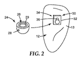
1-3 are various schematic views of an embodiment of an
少なくとも1つの固定具30は、固定具連結具34、及び固定具を歯12の表面13に接続するように適合された基部32を含み得る。例えば、装具10は、第1固定具40、第2固定具42、及び第3固定具44を含み得る。第1固定具40は、固定具連結具34、及び固定具を第1の歯14の表面15に接続するように適合された基部32を含み得る。第2固定具42は、固定具連結具34、及び第2固定具を第2の歯16の表面17に接続するように適合された基部32を含み得る。第3固定具44は、固定具連結具34、及び第3固定具を第3の歯18の表面17に接続するように適合された基部32を含み得る。更に、アーチ部材20は、第1アーチ部材連結具50、第2アーチ部材連結具52、及び第3アーチ部材連結具54を含み得る。第1アーチ部材連結具50は、第1固定具40の固定具連結具34に取り外し可能に接続可能であり得、第2アーチ部材連結具52は、第2固定具42の固定具連結具34に取り外し可能に接続可能であり得、第3アーチ部材連結具54は、第3固定具44の固定具連結具34に取り外し可能に接続可能であり得る。
The at least one
固定具30は、任意の好適な技術又は技術の組み合わせを使用して、歯12の表面14に取り付けられてもよい。例えば、固定具30は、好適な接着剤又はセメントを使用して、歯12の表面に結合することができる。1つ以上の実施形態において、固定具30は、患者の歯の表面(例えば、下側表面)の正確な、予め選択された位置に正確に配置及び結合され得る。この目的のために、米国特許第7,020,963号(Cleary et al.)、同第7,404,714号(Cleary et al.)、及び米国特許公開第2006/0177791号(Cinader et al.)に記載されているもの等の間接的技術を使用するのが有利であり得る。
The
固定具30は、任意の好適な形状、又は形状の組み合わせをとることができ、かつ好適な寸法を有する、固定具連結具34を含み得る。図1〜3に例示される実施形態において、固定具連結具34は、固定具30の基部32から延びるポスト36を含む。ポスト36は、任意の好適な形状又は形状の組み合わせをとることができる。例示される実施形態において、ポスト36は、アーチ部材連結具24の凹部26と係合するように適合された球形の形状を含む。1つ以上の実施形態において、固定具連結具34は、任意の好適な断面形状及び寸法を有し得る。例えば、1つ以上の実施形態において、固定具連結具34は、多角形、楕円形、円錐台形の断面形状を有し得る。固定具連結具34は、固定具30の基部32から延びる、固定具連結具の長さに沿って一定の断面形状及び寸法を有してもよい。1つ以上の実施形態において、固定具連結具34は、固定具連結具の長さに沿って変化する断面形状を有し得る。
The
固定具30は、これが取り付けられる歯に対して任意の好適な矯正力をかけることができるような、形状であり得る。例えば、1つ以上の実施形態において、ポスト36が基部32上に形成又は配置されてもよく、これは、近心−遠心方向と垂直な平面において、歯の表面12への法線に対して任意の好適な角度を形成する軸線に沿って延びている。好適な角度を選択することにより、アーチ部材20によって、これが取り付けられた歯のアンギュレーションを矯正することができる矯正力を歯にかけることができる。1つ以上の実施形態において、ポスト36がそれに沿って延びるような軸線は、これが、近心−遠心方向と平行な平面にいて、歯の表面に対する法線と角度を成すようにして、形成又は配置することができる。好適な角度を選択することにより、アーチ部材20によって、これが歯12のローテーションを矯正することができる矯正力を歯にかけることができる。1つ以上の実施形態において、ポスト36は、歯12のアンギュレーション及びローテーションの両方を矯正することができる、矯正力をもたらすために、これらの両方の面に対して角度を成すように、形成又は配置することができる。
The
固定具30は、任意の適切な材料又は材料の組み合わせを含み得る。例えば、固定具30は、金属性材料、ポリマー材料、ガラス材料、及びこれらの組み合わせを含み得る。1つ以上の実施形態において、固定具30は、アーチ材料本体22に関して記載したものと同じ材料を含み得る。固定具30はまた、任意の好適な形状、又は形状の組み合わせをとることができ、基部は、固定具を歯の表面に接続し、固定具をアーチ部材連結具24に取り外し可能に接続するように適合される。
The
固定具30の基部32は、歯12の任意の好適な表面にフィットするようにカスタマイズされた、歯に面する表面輪郭を有してもよい。例えば、1つ以上の実施形態において、基部32は歯12の下側表面13とフィットするようにカスタマイズされた、歯に面する表面輪郭を有する。カスタマイズされた基部32を有することにより、固定具30は、患者の快適性のために薄く構成することができる。1つ以上の実施形態において、固定具30の基部32は、自己配置「ロック・アンド・キー」機構をもたらすようにカスタマイズすることができ、基部は、固定具30が歯12上の固有の、適切に画定された位置及び方向でのみ取り付けられることを可能にするような輪郭を有する。例えば、米国特許第6,776,614号(Wiechmann et al.)、同第7,811,087号(Wiechmann et al.)、及び同第7,850,451号(Wiechmann et al.)、並びに米国特許公開第2005/0277084号(Cinader et al.)に記載される技術など、カスタマイズされて結合可能な固定具を形成するために任意の好適な技術及び技術の組み合わせを利用することができる。1つ以上の実施形態において、1つ以上の固定具30の基部32は、必ずしも、歯の特定の表面にフィットするようにカスタマイズされていない、任意の好適な形状の表面を含むことができる(すなわち、「一般的」基部)。
The
固定具30は、任意の好適な技術又は技術の組み合わせを使用して、歯12の表面13に取り付けられてもよい。例えば、固定具30は、好適な接着剤又はセメントを使用して、歯12の表面13に結合することができる。固定具30は接着剤により接着される必要はない。例えば、1つ以上の固定具30は歯科矯正バンドに溶接されてもよく、バンドは次に好適なバンドセメントを使用して対応する歯12に固定される。1つ以上の実施形態において固定具30は、結合可能な舌側ボタン、又は他の市販の既製の結合可能な装具である。更に、固定具30全体がTRANSBONDブランドの光硬化型接着剤(3M Company,St.Paul,MNから入手可能)等の硬化性複合歯科材料から形成されてもよく、米国特許出願公開第2007/0031774号(Cinader et al.)に記載されているもの等の技術を用いて、患者の歯上でin vivoで硬化されてもよい。
The
アーチ部材20が1つ以上の固定具に接続される。1つ以上の実施形態において、アーチ部材20は、自己結紮式アーチ部材であり得る。更に、アーチ部材20は、アーチ部材本体22、及び本体に接続された1つ以上のアーチ部材連結具24を含む。1つ以上の実施形態において、アーチ部材連結具24は、本体22と一体であり得る。アーチ部材20は任意の好適な数のアーチ部材連結具24(例えば、1個、2個、3個、4個、5個、又はそれ以上の連結具)を含むことができる。フェースシール24は、任意の好適な技術又は技術の組み合わせを使用してアーチ部材本体22に接続することができる。1つ以上の実施形態において、アーチ部材連結具24は、例えば、溶接、接着剤を使用した接着など、任意の好適な技術又は技術の組み合わせを使用して、アーチ部材本体22に取り付けることができる。1つ以上の実施形態において、アーチ部材連結具24は、アーチ部材本体22と一体形成することができ、これによってアーチ部材連結具は、アーチ部材本体22と一体となる。
1つ以上の実施形態において、アーチ部材連結具24は、アーチ部材本体22に接続することができ、固定具連結具34を介してアーチ部材連結具に接続された固定具30がアーチ部材本体に対して変位するように適合される。1つ以上の実施形態において、固定具30は、固定具がアーチ部材本体に対して摺動し得るように、アーチ部材本体22に対して変位するように適合されている。1つ以上の実施形態において、固定具30は、アーチ部材本体22に沿って摺動することができる。1つ以上の実施形態において、固定具30は、アーチ部材本体22に対して移動し得る。1つ以上の実施形態において、アーチ部材本体は、固定具30に対して移動することができる。1つ以上の実施形態において、固定具30及びアーチ部材本体22は、互いに移動することができる。例えば、アーチ部材連結具24は、固定具30の固定具連結具34のポスト36と取り外し可能に係合するように適合された凹部26を含み得る(図2に示される)。1つ以上の実施形態において、弾性ライナー29は凹部26内に配置され得る。弾性ライナー29は、固定具連結具34のポスト36に取り外し可能に係合するように適合され得る。アーチ部材連結具24は、1つ以上の実施形態において、接続されたときに、固定具連結具34を囲むことができる。
In one or more embodiments, the
1つ以上の実施形態において、アーチ部材連結具24は、図3に示される連結具を通じて形成されたチャネル28を含み得る。アーチ部材本体22はチャネル28内に配置され得る。1つ以上の実施形態において、アーチ部材本体22は、本体が、アーチ部材連結部に摺動自在に接続されるように、チャネル28内でアーチ部材連結部24に対して動くことができる。チャネル28は、例えば、チャネル内に配設されたアーチ部材本体22の部分と同じ断面形状など、任意の好適な断面形状又は形状の組み合わせをとることができる。更に、チャネル28は、任意の好適な寸法を有することができる。1つ以上の実施形態において、チャネルは、チャネル内に配設されたアーチ部材本体22の一部分の断面積よりも大きな断面積を有し、これによりアーチ部材本体は、アーチ部材連結具24に対して動くか、又は摺動することができる。いくつかの実施形態において、チャネルの寸法は、規格又は他の治療に関連する制約によって、規定され得る。
In one or more embodiments, the
1つ以上の実施形態において、チャネル28は、アーチ部材連結具24が固定具連結具34に接続されるときに、近心−遠心方向に対して任意の好適な角度を形成する軸に沿って延びるように、アーチ部材連結具24を通じて形成され得る。更に、1つ以上の実施形態において、アーチ部材連結具24は、チャネル28の軸線が、歯列弓に沿って、近心−遠心方向に対して任意の好適な角度を形成するように、固定具連結具34に接続することができる。チャネル28を、近心−遠心方向に対する一定の角度で形成する、又は配置することによって、選択された矯正力(例えば、ローテーション、アンギュレーションなど)が、取り付けられた歯に適用され得る。
In one or more embodiments, the
アーチ部材連結具24は、任意の適切な材料又は材料の組み合わせを含み得る。1つ以上の実施形態において、アーチ部材連結具24は、アーチ材料本体22に関して記載したものと同じ材料又は材料の組み合わせを含み得る。アーチ部材連結具24はそれぞれ、同じ材料又は材料の組み合わせを含み得る。1つ以上の実施形態において、1つ以上のアーチ部材連結具24は、1つ以上の追加的なアーチ部材連結具24とは異なる材料を含んでもよい。
アーチ部材連結具24は、アーチ部材連結具が、1つ以上の固定具連結具34に取り外し可能に接続可能であるように、任意の好適な形状、又は形状の組み合わせをとることができる。取り外し可能な連結具の例は、交付済み米国特許第6,302,688号(Jordan et al.)、同第6,582,226号(Jordan et al.)、同第7,014,460号(Lai et al.)、同第7,252,505号(Lai)及び同第8,827,697号(Cinader et al.)、並びに係属中の米国特許出願公開第2005/0277084号(Cinader et al.)に記載されている。1つ以上の実施形態において、アーチ部材連結具24及び固定具連結具34はそれぞれ、装具10が1本以上の歯のアンギュレーションを矯正するための力をもたらし得るように、2つ以上の辺を有する断面形状を含み得る。アーチ部材連結具24及び固定具連結具を介して、歯に接続されるものとして示されているが、1つ以上の実施形態において、アーチ部材本体22の一部分は、例えば、歯の表面への直接的な結合など、任意の好適な技術又は技術の組み合わせを使用して、歯12の表面13に直接取り付けられるように適合されてもよい。アーチ部材連結具24は、任意の好適な技術又は技術の組み合わせを使用して固定具連結具34に取り外し可能に接続されてもよい。例えば、アーチ部材連結具24の凹部26は、ポスト36と係合することができ、連結具の間の接続を維持するために、アーチ部材連結具及び固定具連結具に、接着剤が適用されてもよい。1つ以上の実施形態において、アーチ部材連結具24と、固定具連結具34との間の接続の維持を補助するために、クランプ、ワイヤ、又は他の装置を利用することができる。
The
装具10は、様々な種類の歯の動きを生じることができる。アーチ部材本体22、及び固定具30の固定具連結具34の構成、並びにアーチ部材本体(例えば、アーチ部材本体の変形による)固定具に対する変位により、装具10は、従来的なアライナ及びワイヤを埋め込んだ装具を使用する場合に達成が困難であり得る方法で歯を動かすことができる。アーチ部材本体22の1つ以上の部分が様々な構成に形成され得るため、装具10は内−外及び近心側−遠心側の歯の動き、並びに歯を傾ける及び回転させる動きの任意の組み合わせを生み出す可能性を有する。アーチ部材本体22の長手方向軸線と平行な歯の並進移動は、1つ以上の柔軟なばねをアーチ部材本体に組み込むこと、又はアーチ部材本体内に1つ以上のばねを形成することによって、生じさせることができる。
The
固定具が歯の表面に接続され、アーチ部材連結具24が固定具連結具34に接続されるとき、1つ以上の固定具30は、アーチ部材本体22に対して変位するように適合され得る。例えば、図1〜3に例示される実施形態において、アーチ部材本体22は、アーチ部材連結具24のチャネル28内に配置され、アーチ部材連結具24に対して移動することができる。アーチ部材連結具24が、固定具30の固定具連結具34に取り外し可能に接続されるとき、アーチ部材連結具及び固定具連結具は、相対的に固定されたままである。しかしながら、1つ以上の実施形態においてアーチ部材本体22は、固定具に対して変位することができ、アーチ部材本体は、チャネル28内で摺動する(例えば、固定具はアーチ部材本体に対して摺動し得る)。1つ以上の実施形態において、固定具30のアーチ部材本体22に対して移動する能力により、アーチ部材本体22とアーチ部材連結具24との間の摩擦が減少して、治療の初期段階において歯をより早く移動させることができる。
One or
アーチ部材連結具24及び固定具連結具34は、アーチ部材連結具が固定具の固定具連結具に接続されるときに、アーチ部材本体22及び1つ以上の固定具30が固定した関係になるように、適合させることができる。換言すると、固定具連結具34及びアーチ部材連結具24が接続されるとき、アーチ部材連結具24に隣接するアーチ部材本体22は固定されて、固定具に対し、これが取り付けられた歯12の表面13と平行な方向に移動することができない。すなわち、アーチ部材本体は、固定具に対して摺動することができない。
The
連結具24、34を互いに接続及び分離するのに必要な力は、患者がアーチ部材20を容易に挿入及び取り外しできるように十分に小さくすることができる。1つ以上の実施形態において、これらの力は、アーチ部材20が治療中、患者の歯科構造にしっかり接続し、固定具30のいずれかから偶発的に分離しないように、十分に強くすることができる。即ち、連結具24、34は、通常の矯正力及び治療中に生じる他の力に供された場合でも、接続した状態を維持し得る。1つ以上の実施形態において、連結具24、34は、可能な限り小さい係合力を生じるように適合される。1つ以上の実施形態において、係合離脱力は、係合離脱が患者に不快感を与える程大きくはなく、治療中に自然に係合離脱が生じる程小さくもない。係合及び係合離脱力の最適値は、歯によってかなり異なり、ワイヤ部材本体22の構成にも一部依存し得る。1つ以上の実施形態において、連結具24、34を分離するのに必要な力は、医師のみがアーチ部材20を取り外せるようなものであり得る。
The force required to connect and disconnect the
アーチ部材20は、患者の歯に歯科治療又は一連の歯科治療を行うために、固定具30を介して患者の1本以上の歯に矯正力(単数又は複数)を加えることができる。アーチ部材20のアーチ部材本体22は、剛性及び弾性などの、広範な材料特性をもたらす、任意の好適な材料又は材料の組み合わせを含む場合がある。例えば、アーチ部材本体22は、金属性材料、ポリマー材料、ガラス材料、及びこれらの組み合わせを含み得る。1つ以上の実施形態において、アーチ部材本体22は、ニチノール、ステンレス鋼、ニッケルチタン、及びベータチタンのうちの少なくとも1つを含み得る。アーチ部材本体22は、一体型本体であってもよく、又は材料の1つ以上の層を含んでもよい。更に、アーチ部材本体22は、その長さに沿って一体であってもよい。1つ以上の実施形態において、アーチ部材本体22は、任意の好適な技術又は技術の組み合わせを使用して、一緒に接続された、いくつかの部分を含み得る。
The
アーチ部材本体22はまた、医師の要求に基づいて個々に構成することもできる。例えば、所定のアーチ部材本体22は、高いレベルの矯正力が所望される場合はステンレス鋼から、比較的低いレベルの力が所望される場合はニッケルチタンから、中間レベルの力が所望されるベータチタンから作製されてもよい。1つ以上の実施形態において、本体22は、ポリマー又は充填複合材料など、非金属製材料を含む、他の材料を含んでもよい。更に、本体22の断面形状は、所望の矯正力(単数又は複数)を生じるよう調整することができる。更に、本体22の形状及び/又は断面寸法(例えば、厚さ)は、所望の矯正力(単数又は複数)を生じるよう調整することができる。1つ以上の実施形態において、アーチ部材本体22は、本体の長さに沿って変化する断面形状を有し得る。
The
アーチ部材本体22は、任意の好適な断面形状、例えば、形状、面積、向きなどを含むことができる。断面形状はアーチ部材本体22の長さに沿って、一定であってもよく、又は変化していてもよい。例えば、アーチ部材本体22は、任意の好適な形状、又は形状の組み合わせをとることができる。アーチ部材本体22は、任意の好適な断面形状、例えば、多角形(例えば、三角形、矩形など)、楕円形などを含んでもよい。アーチ部材本体22の断面形状は、本体の長さに沿って均一であってもよい。1つ以上の実施形態において、アーチ部材本体22の第1部分は第1断面形状を有してもよく、アーチ部材本体の第2部分は、第1断面形状とは異なる第2断面形状を有してもよい。アーチ部材本体22は、均一の断面積を有してもよく、又は本体の長さに沿って異なる断面積を有してもよい。
The
1つ以上の実施形態において、アーチ部材本体22の縁部は、患者に更なる快適性をもたらすために、本体が形成された後に平滑化されてもよい。更に、1つ以上の実施形態において、アーチ部材本体22の1つ以上の部分は、快適性を向上させるために本体の縁部を被覆するコーティングをもたらすために、任意の好適な材料又は材料の組み合わせによってコーティングされていてもよい。アーチ部材22はまた、本体の、アーチ部材連結部24の間の部分に適用される1つ以上の保護カバーで被覆されてもよく、これにより、本体は鋭い角部を有さないが、本体に対して移動して、患者の歯に矯正力(単数又は複数)をかけることができる。カバーは、任意の好適な材料、又は材料の組み合わせを含み得る。1つ以上の実施形態において、カバーは、任意の所望の審美的外観をもたらし得る。更に、カバーは、カバーの審美性を維持するための、耐汚染材料(単数又は複数)を含む場合がある。
In one or more embodiments, the edges of the
アーチ部材本体22は、2つ以上のアーチ部材連結具24の間に任意の好適な矯正力をもたらすように適合され得る。これらの矯正力をもたらすために、任意の好適な技術又は技術の組み合わせを利用することができる。例えば、図9は、アーチ部材420の一実施形態の一部分の概略斜視図である。図1〜図3の歯科矯正装具10のアーチ部材20に関する設計検討及び可能性は全て、図9のアーチ部材420に等しく当てはまる。更に、アーチ部材420は、アーチ部材本体422、及び本体に接続されたアーチ部材連結具424を含む。
1つ以上の実施形態において、アーチ部材本体422の断面形状(例えば、面積)は、本体の長さに沿って変化し得る。例えば、アーチ部材連結具450と、アーチ部材連結具452との間に配置された、アーチ部材本体422の第1部分460は、第1断面形状を有する。アーチ部材本体422はまた、アーチ部材連結具454と、アーチ部材連結具456との間に配置され、第2断面形状を有する、第2部分462を含む。1つ以上の実施形態において、第1部分460における第1断面形状は、第2部分462における第2断面形状とは異なる。アーチ部材本体422の断面形状は、本体の長さに沿った任意の好適な平面(単数又は複数)において変化し得る。1つ以上の実施形態において、アーチ部材本体422の厚さは変化して、いずれか2つの固定具連結具24の間(本体のその区分の一部分において、又はその間で連続的に)の本体の断面形状を変化させてもよい。例えば、1つ以上の実施形態において、アーチ部材本体422の厚さは、図1に示されるようにアーチ部材420が1つ以上の固定具30を介して患者の1本以上の歯12に接続されるときに、近心−遠心方向と平行、及び歯の表面と垂直な平面において変化し得る。例えば、1つ以上の実施形態において、アーチ部材本体422の厚さは、アーチ部材420が1つ以上の固定具30を介して患者の1本以上の歯12に接続されるときに、顔−舌、又は咬合−歯肉方向と垂直な平面内において、及びアーチ部材の近心−遠心長さに沿って、歯の表面と平行な平面において、変化していてもよい。
In one or more embodiments, the cross-sectional shape (eg, area) of the
アーチ部材本体422の断面形状は、アーチ部材本体の1つ以上の部分における所望の曲げ剛性をもたらすように選択することができる。アーチ部材本体422の曲げ剛性を調整することによって、アーチ部材本体の長さに沿って変化し得る、選択された矯正力をもたらすことができる。例えば、1つ以上の実施形態において、アーチ部材本体422の第2部分462は、第2部分が第1部分の断面積よりも小さい断面積を有するために、第1部分460よりも小さい矯正力をもたらすことができる。アーチ部材本体422の2つの部分460、462は、本体の長さに沿って変化する断面形状を有するものとして示されるが、アーチ部材本体の任意の好適な部分(単数又は複数)が、アーチ部材420のアーチ部材連結具424の間に1つ以上の矯正力をもたらすために、変化する断面形状を有してもよい。
The cross-sectional shape of the
図9には示されないが、アーチ部材本体422の断面積もまた、アーチ部材連結具424に接続された本体の部分(単数又は複数)に沿って変化してもよい。例えば、アーチ部材本体422の断面積は、アーチ部材連結具450に接続される部分において小さくすることができ、よってこの部分に隣接する本体の部分は、より大きな断面積を有する。アーチ部材連結具450を通じて形成されるチャネルは、連結具に隣接するアーチ部材本体の部分のより大きな断面積のために、連結具が、より小さい断面積を有する部分に沿った位置にとどまり、アーチ部材本体から摺動して外れ得ないように、選択することができる。この断面積の変化は、アーチ部材本体422の長さに沿った1つ以上のアーチ部材連結具224の動きを制限することによって、医師がアーチ部材420を患者の歯に適用するのを補助することができる。
Although not shown in FIG. 9, the cross-sectional area of the
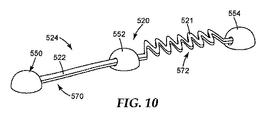
アーチ部材本体の形状は、アーチ部材のアーチ部材連結具の間に1つ以上の矯正力をもたらすために、任意の好適な平面内において変化させることができる。アーチ部材本体は、任意の好適な形状、又は形状の組み合わせをとることができる。例えば、図10は、アーチ部材520の別の実施形態の一部分の概略斜視図である。図1〜3のアーチ部材20及び図9のアーチ部材420に関する設計検討及び可能性は全て図10のアーチ部材520に等しく当てはまる。アーチ部材520は、アーチ部材本体522、及びアーチ部材本体に接続されたアーチ部材連結具524を含む。アーチ部材本体522は、アーチ部材連結具550と、552との間に、第1非線形部分570を含む。更に、アーチ部材本体522は、アーチ部材連結具552と、554との間に、第2非線形部分572を含む。第1非線形部分570は、第2非線形部分572の第2形状と同じ第1形状をとり得る。1つ以上の実施形態において、第1形状は、第2形状と異なる場合がある。任意の好適な形状又は形状の組み合わせは、アーチ部材本体522内に形成され得る。1つ以上の実施形態において、第1非線形部分570、及び第2非線形部分572の少なくとも一方が、例えば、U字型、V字型、S字型、正弦波状などであり得る。例えば、第1非線形部分150は、アーチ部材120が、固定具(例えば、図1〜3の固定具30)を介して1本以上の歯と接続されるときに、歯肉、咬合、近心及び遠心方向の少なくとも1つに延びる正弦波形状をとる場合がある。
The shape of the arch member body can be varied in any suitable plane to provide one or more corrective forces between the arch member connectors of the arch member. The arch member body can take any suitable shape or combination of shapes. For example, FIG. 10 is a schematic perspective view of a portion of another embodiment of
第1非線形部分570及び第2非線形部分572は、いずれかの方向、又は方向の組み合わせに延びることができる。例えば、1つ以上の実施形態において、第1及び第2固定具(例えば、図1の固定具40、42)が第1及び第2の歯(例えば、第1の歯14、及び第2の歯16)の表面(例えば、表面15、17)に接続され、第1固定部材連結具550、及び第2アーチ部材連結具552が、第1固定具の固定具連結具、及び第2固定具の固定具連結具にそれぞれ接続されるとき、第1非線形部分570及び第2非線形部分572の少なくとも一方が、歯肉、咬合、唇、及び舌側方向の少なくとも1つに延びることができる。
The first
例えば、1つ以上の実施形態において、アーチ部材本体522の形状は、アーチ部材520が1本以上の歯に接続された1つ以上の固定具(図示されない)の固定具連結具に接続されるときに、近心−遠心方向と平行な平面、及び歯の表面と垂直な平面において変化し得る。1つ以上の実施形態において、アーチ部材本体522の形状は、近心−遠心方向と垂直な平面、及び歯の表面と平行な平面において変化し得る。1つ以上の実施形態において、第2非線形部分572は、弓状部分、例えば、ばね521などの正弦波形状部分を含み得る。任意の好適なばね、又はばねの組み合わせを使用することができる。ばね521は、所望の矯正力をかけるために、張力又は圧縮力のいずれかをより容易にかけられるように、患者の口内に挿入することができる。
For example, in one or more embodiments, the shape of the
1つ以上の実施形態において、第1非線形部分570は、アーチ部材連結具550及び552に接続された、一方又は両方の歯に、第1矯正力をかけるように適合された、第1形状を有することができる。更に、第2非線形部分572は、アーチ部材連結具550及び552に取り付けられた、一方又は両方の歯に、第2矯正力をかけるように適合された、第2形状を有することができる。第1矯正力は、第2矯正力と同じであり得る。1つ以上の実施形態において、第1矯正力は、第2矯正力とは異なる。
In one or more embodiments, the first
アーチ部材本体522の1つ以上の部分は、変化する断面形状、及び非線形の形状(単数又は複数)を含み得る。例えば、第2非線形部分572はまた、その部分の長さに沿って変化する断面形状を含む場合があり、例えば、その部分の厚さがばね521に沿って変化し得る。
One or more portions of the
図1〜3に戻り、アーチ部材本体22は、アーチ部材連結具の間に、1つ以上の非線形部分56、58、60を含み得る。非線形部分、例えば、非線形部分56、58の1つ以上は、固定具30によって装具10に接続された歯の表面15、17から離れるように適合されてもよい。例えば、図1に示されるように、第1アーチ部材連結具50と第2アーチ部材連結具52との間にある、アーチ部材本体22の第1非線形部分56は、第1固定具40及び第2固定具42が、第1及び第2の歯の表面に接続され、第1アーチ部材連結具50、及び第2アーチ部材連結具52が第1固定具40及び第2固定具42の固定具連結具に取り外し可能に接続されるときに、第1の歯14及び第2の歯16の表面15、17から離れるように適合され得る。第1非線形部分56は、第1の歯14及び第2の歯16の表面15、17から、任意の好適な距離だけ離れていてもよい。第1非線形部分56は、第1の歯14及び第2の歯16の表面15、17それぞれから、同じ距離だけ離れていてもよい。1つ以上の実施形態において、第1非線形部分56は、第1の歯14の表面15から、第1非線形部分と第2の歯16の表面17との間の距離とは異なる距離だけ、離れていてもよい。アーチ部材本体22の、任意の好適な数の部分は、装具10が接続される歯の表面から離れていてもよい。1つ以上の実施形態において、アーチ部材本体22全体が、これが接続される歯12の表面から離れていてもよい。1つ以上の実施形態において、アーチ部材本体22の部分が1つ以上の歯と接触している一方で、アーチ部材本体の1つ以上の追加の部分が、追加の歯から離れていてもよい。
1-3, the
アーチ部材20及び固定具30の一方又は両方が、選択された治療を患者に行うために利用され得る、他の装置又は要素を含んでいてもよい。例えば、1つ以上の実施形態において、2つのアーチ部材連結具24の間の非線形部分の選択された形状は、フック、ツイスト、ステップ、ループ、及びばねの少なくとも1つを含んでもよい。例えば、アーチ部材本体22は、長手方向(すなわち、アーチ部材本体の長さにほぼ沿った方向)の移動を可能にする、1つ以上の可撓性ばね(例えば、図5のばね521)を含んでもよい。ばねは、アーチ部材本体22と一体であってもよく、又は本体とは別個に作製されて、任意の好適な技術又は技術の組み合わせによって本体に接続されてもよい。ばねはまた、アーチ部材本体22の柔軟性を増加させることができる。1つ以上の実施形態において、ばねは弾性であり得、長手方向に張力又は圧縮力をかけることができる。Z−ばね、コイルばね、オメガループ、プッシュロッド、又はそれらの任意の組み合わせを含む様々な種類のばねを使用することができる。各アーチ部材本体22の柔軟性を増加させ、長手方向の撓みを可能にすることにより、歯が不正咬合である場合に、アーチ部材連結具24及び固定具連結具34の接続を促進することができる。患者の治療計画に基づき、ばねはアーチ部材本体22の任意の好適な部分(単数又は複数)に沿って設けることができる。アーチ部材20は、アーチ部材連結具24と、固定具連結具34との間の接続を維持するために、固定具30の少なくとも1つと係合するように適合され得る、1つ以上のタングを含み得る。
One or both of the
アーチ部材本体22は、任意の好適な技術、又は技術の組み合わせを使用して製造することができる。1つ以上の実施形態において、アーチ部材本体22は、基材(例えば、材料のシート)から、基材の部分(単数又は複数)を取り除くことによって、形成することができる。例えば、ニチノール基材は、アーチ部材本体22を形成するように切断する、又はエッチングすることができる。例えば、レーザ切断、水ジェット切断、エッチング(例えば、イオンビームエッチング)、ダイカットなど、任意の好適な技術又は技術の組み合わせを利用して、基材を切断又はエッチングすることができる。
The
アーチ部材本体22は、任意の好適な技術又は技術の組み合わせを使用して、人の好適な形状又は形状の組み合わせへと形成することができる。例えば、アーチ部材本体22の形状は、基材からアーチ部材を切断又はエッチングする際に形成することができる。1つ以上の実施形態において、アーチ部材本体22を形成し、その後、例えば、曲げ、機械加工などの任意の好適な技術を仕様して、1つ以上の形状に成形することができる。アーチ部材本体22の1つ以上の形状は、例えば、熱硬化など、任意の好適な技術又は技術の組み合わせを仕様して硬化させることができる。
The
本明細書において記載されるように、アーチ部材本体22は、本体の長さに沿って、任意の好適な断面形状を有することができる。1つ以上の実施形態において、アーチ部材本体22は、アーチ部材本体が、装具10の1つ以上の固定具30に接続される際に、アーチ部材本体22の長さに沿って変化する、咬合方向における厚さを有し得る。アーチ部材本体22の厚さを変えることにより、1本以上の歯に適用される矯正力の制御がもたらされ得る。この厚さは、任意の好適な技術又は技術の組み合わせを使用して変えることができる。1つ以上の実施形態において、この厚さは、アブレーション、エッチング、研磨、切削などにより、アーチ部材本体22の部分を取り除くことによって変えることができる。アーチ部材本体22は、1つ以上の部分を長くすることによって、この部分の厚さを減少させることができる。
As described herein, the
歯科矯正装具10は、任意の好適な技術、又は技術の組み合わせを使用して製造することができる。例えば、1つ以上の実施形態において、アーチ部材20及び固定具30の一方又は両方を、高速製造技術を使用して製造することができる。1つ以上の実施形態において、固定具連結具34及びアーチ部材連結具24は、メーカー又は医師のいずれかにより、標準ライブラリから選択され得る。同様に、アーチ部材本体22は、医師の治療目標を達成するために、標準ライブラリから選択され、修正されてもよい。治療の各段階における歯の目標位置は、ソフトウェア又は技術者によって提案され、必要に応じて、医師により修正され得る。例えば、共有米国特許出願公開第2010/0260405号(Cinader et al.)に記載されるように、治療中、歯の目標位置の1つ以上が、歯の中間走査に含まれる情報から生成され得る。治療の開始時に一連の装具全てを製造するのではなく、後続の装具を必要に応じて製造することができる。1つ以上の実施形態において、医師は、医院で装具を全て製造することができる。これは、治療の進行と共に、装具を調節する際の柔軟性を医師にもたらし得る。
The
例えば、1つ以上の実施形態において、アーチ部材20及び固定具30の一方又は両方を、3D印刷技術を使用して製造することができる。例えば、医師により1つ以上のデータファイルが選択され得、これにより後に、3D印刷技術を使用して、歯科矯正装具10を製造することができる。
For example, in one or more embodiments, one or both of the
アーチ部材連結具24及び固定具連結具34は、アーチ部材連結具が、固定具連結具に取り外し可能に接続可能であるように、任意の好適な方法で設計することができる。例えば、図4は、固定具130及びアーチ部材連結具124の概略斜視図である。固定具130及び固定具部材連結具124は、例えば、図1〜3の装具10など、任意の好適な歯科矯正装具の一部であり得る。レスピレータ130は、固定具連結具134及び基部132を含み得る。基部132は、固定具を歯の表面に接続するように適合されている。アーチ部材連結具124は、固定具連結具134に取り外し可能に接続可能である。例えば、アーチ部材連結具124は、凹部126内に配置された1つ以上のタブ121を含む。更に、固定具130は、アーチ部材連結具が固定具130に取り外し可能に接続可能であるように、アーチ部材連結具124のタブ121を受け入れるように適合された、1つ以上のスロット131を含む。1つ以上の実施形態において、アーチ部材連結具124は、タブ121が、固定具連結具134のスロット131と係合する際に伸張する、弾性材料を含み得る。接続されたとき、アーチ部材連結具124は、固定具連結具134を囲む。
The
1つ以上の実施形態において、アーチ部材連結具124は、アーチ部材本体の一部分がその内部に配置され得るように適合された、チャネル128を含む。1つ以上の実施形態において、アーチ部材本体は、チャネル128の内部に摺動自在に配置されてもよく、これにより固定具130は、アーチ部材連結具が固定具連結具134に接続されるときに、アーチ部材本体に対して変位することができる。この変位を可能にするため、アーチ部材連結具124は、アーチ部材本体がチャネル128内に配置されるときに、固定具連結具134がアーチ部材本体の変位と干渉しないように、固定具連結具134と、チャネル128に隣接する凹部126の内側表面との間に空間が設けられるような、大きさとすることができる。1つ以上の実施形態において、アーチ部材連結具124及び固定具連結具134の両方が、チャネル128、138を含んでもよく、アーチ部材本体の一部が、アーチ部材連結具及び固定具連結具のチャネル内に配置され得る。このような実施形態において、アーチ部材本体は、アーチ部材連結具及び固定具連結具が接続された後に、アーチ部材連結具124及び固定具連結具134のチャネル128、138内に配置することができる。
In one or more embodiments, the
図5〜6は、歯科矯正装具200の別の実施形態の一部分の概略斜視図である。図1〜図3の歯科矯正装具10に関する設計検討及び可能性は全て、図5〜6の歯科矯正装具200についても等しく当てはまる。歯科矯正装具200は、アーチ部材本体(明確に示されていない)、及びこの本体に接続されたアーチ部材連結具224を含む、アーチ部材220を含む。装具200はまた、固定具連結具234、及び固定具を歯212の表面214に接続するように適合された基部232を含む、固定具230も含む。1つ以上の実施形態において、アーチ部材連結具224は、固定具連結具234に取り外し可能に接続可能である。更に、1つ以上の実施形態において、固定具230が歯212の表面214に接続され、アーチ部材連結具224が固定具連結具234に接続されるとき、固定具230は、アーチ部材本体に対して変位するように適合される。
5-6 are schematic perspective views of a portion of another embodiment of an
固定具230は、ポスト236の形態の固定具連結具234を含んでもよい。ポスト236は、スロット又はアンダーカット部分231を含む。スロット231は、任意の好適な形状又は形状の組み合わせをとることができる。図5〜6に例示される実施形態において、スロット231は、ポスト236の各側部に形成される。1つ以上の実施形態において、スロット231は、ポスト236の、1つ、2つ、3つ、4つ、又はいずれかの数の側部に形成することができる。ポスト236が、楕円形の断面を含む1つ以上の実施形態において、スロット231は、ポスト236の楕円形表面に沿って形成することができる。
The
更に、アーチ部材連結具224は、1つ以上のタブ221を含む。アーチ部材連結具224は、任意の適切な数のタブ221を含み得る。1つ以上の実施形態では、タブ221は弾性であり得る。例えば、タブ221は、アーチ部材連結具224が固定具連結具234と係合する際に撓む、衣料品のスナップに使用されるものと同様の1つ以上のワイヤを含み得る。固定具連結具234のスロット231は、固定具連結具232がアーチ部材連結具にスナップフィットするようにして、アーチ部材連結具224のタブ221を受け入れるように適合され得る。アーチ部材連結具224はまた、アーチ部材本体(図示されない)の一部を受け入れるように適合されたチャネル228を含み得る。
In addition, the
1つ以上の実施形態において、固定具が歯214の表面214に接続され、アーチ部材連結具224が固定具連結具234に接続されるとき、固定具230は、アーチ部材本体に対して変位するように適合される。例えば、アーチ部材本体が、固定具230に対して摺動し得るように、アーチ部材本体の一部がチャネル228内に配置されてもよい。1つ以上の実施形態において、チャネル228は、アーチ部材連結具224のチャネル本体223内に形成されてもよい。チャネル本体223は、弾性タブ221に取り付けられてもよい。チャネル本体223をタブ221に取り付けるために、任意の好適な技術又は技術の組み合わせを利用することができる。1つ以上の実施形態において、チャネル本体223はタブ221と一体化されて、一体型アーチ部材連結具224を形成してもよい。
In one or more embodiments, the
チャネル本体223は、アーチ部材本体22の変形と組み合わせて、例えば、トルク、アンギュレーション、ローテーションなど、いずれかの所望の矯正力を1本以上の歯にかけるように適合されてもよい。例えば、チャネル本体223は、チャネル223が表面14と垂直な平面内において、近心−遠心方向と角度を形成する軸に沿って延びるようにして、固定具230と共に形成されるか、又は固定具に取り付けられてもよい。この角度を形成することによって、取り付けられた歯212に回転矯正力をかけて、歯のローテーションを矯正することができる。
The
装具200は、アーチ部材連結具と固定具連結具234との間の接続の維持を補助するために、アーチ部材連結具224のタブ221の1つ以上に係合するように適合されたクランプ227を含むことができる。クランプ227は、任意の好適な材料又は材料の組み合わせを含み、任意の好適な形状をとることができる。1つ以上の実施形態において、クランプ227は、タブが固定具230のスロット231と係合したままで、アーチ部材連結具224の外側表面の上で摺動し、タブ221と係合し得る弾性oリングであってもよい。
The
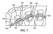
図7〜8は、歯科矯正装具300の別の実施形態の一部分の概略斜視図である。図1〜図3の歯科矯正装具10に関する設計検討及び可能性は全て、図7〜8の装具300についても等しく当てはまる。装具300は、アーチ部材本体322、及びアーチ部材本体に接続された1つ以上のアーチ部材連結具324を含む、アーチ部材320を含む。1つ以上のアーチ部材連結具224はアーチ部材本体322のスロット付き部分326を含む場合がある。スロット付き部分326は、任意の好適な形状、又は形状の組み合わせをとることができ、かつ任意の好適な寸法であり得る。1つ以上の実施形態において、スロット付き部分326は、任意の好適な技術又は技術の組み合わせを使用して形成することができる。1つ以上の実施形態において、アーチ部材本体322が、任意の好適な技術又は技術の組み合わせを使用して形成されるときに、スロット付き部分326を形成することができる。1つ以上の実施形態において、スロット付き部分326は、アーチ部材本体322が形成された後に形成することができる(例えば、アーチ部材本体を切断する、又はエッチングすることによってスロット付き部分を形成することができる)。1つ以上の実施形態において、スロット付き部分326は弾性である。
FIGS. 7-8 are schematic perspective views of a portion of another embodiment of an
装具300はまた、固定具連結具334、及び固定具を歯312の表面314に接続するように適合された基部332をそれぞれ含み得る、1つ以上の固定具330も含む。1つ以上の固定具連結具334は、アーチ部材本体322のスロット付き部分326を受け入れるように適合されたスロット331を含み得る。1つ以上の実施形態において、固定具連結具334のスロット331は、スロット331内にアーチ部材本体322のスロット付き部分326を保持する、アンダーカット部分(単数又は複数)を含み得る。スロット331は任意の好適な寸法を含み、任意の好適な形状又は形状の組み合わせをとり得る。1つ以上の実施形態において、スロット付き部分がスロット内に摩擦嵌めされるように、スロット331は、歯312の表面314と垂直な方向に、アーチ部材本体322のスロット付き部分326の幅よりも小さな幅を有してもよい。アーチ部材320は、アーチ部材を、スロット331内へと、歯肉方向に押し込むことによって、固定具330に接続することができる。1つ以上の実施形態において、スロット331は、その幅が、固定具330が取り付けられる歯312の表面314と実質的に平行になるように配置することができ、アーチ部材320は、アーチ部材をスロット331内へと遠心方向で押し込むことによって、固定具に接続され得る。更に、スロット331は、固定具330内に形成されてもよく、又は別個に製造されて、固定具の基部332に取り付けられてもよい。
The
1つ以上の実施形態において、アーチ部材連結具324は、固定具連結具334に取り外し可能に接続可能である。更に、1つ以上の実施形態において、固定具連結具334のスロット331、及びアーチ部材本体322のスロット付き部分326は、スロット付き部分がスロットに対して動けるように適合される。したがって、このような実施形態において、固定具が歯312の表面314に接続され、アーチ部材連結具324が固定具連結具334に接続されるとき、固定具330は、アーチ部材本体322に対して変位するように適合される。1つ以上の実施形態において、スロット331及びアーチ部材本体322は、アーチ部材本体のスロット付き部分326が、スロットの長さと実質的に平行な方向、例えば、歯312の表面314と実質的に平行な方向に動けるように、適合されている。1つ以上の実施形態において、固定具連結具334のスロット331、及びアーチ部材本体322のスロット付き部分326は、アーチ部材本体が、固定具330に対して近心−遠心方向に動けるように適合される。
In one or more embodiments, the
一般的に、アーチ部材及び固定具の様々な実施形態は、選択される治療を行うために互換的に使用することができる。例えば、1つの代表的な実施形態において、患者の1本以上の歯が、図8〜9に例示される装具300の固定具330に接続され、固定具が、アーチ部材連結具324を含むアーチ部材に連結されてもよく、1つ以上の追加の歯が、図1〜3に例示される、装具10の固定具30に接続され、固定具が1つ以上のアーチ部材連結具24に連結されてもよい。1つ以上の実施形態において、装具の異なる実施形態が、治療の異なる段階で使用されてもよい。例えば、図8〜9の装具300は、治療の初期段階で利用されてもよく、図1〜3の装具10は、同じ患者の後の治療段階で利用されてもよい。
In general, the various embodiments of arch members and fasteners can be used interchangeably to perform a selected treatment. For example, in one exemplary embodiment, one or more teeth of a patient are connected to a
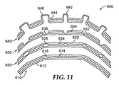
患者の1本以上の歯に選択される矯正力をかけるために、任意の好適な技術又は技術の組み合わせを利用することができる。例えば、図11は、アーチ部材のセット600の概略平面図である。図1〜4のアーチ部材20に関する設計検討及び可能性は全て、図11のアーチ部材のセット600のアーチ部材それぞれにも等しく当てはまる。アーチ部材のセット600は、例えば、図1〜4の歯科矯正装具10など、任意の好適な歯科矯正装具と共に利用することができる。第1アーチ部材610は、アーチ部材本体612、アーチ部材連結具614、及びアーチ部材本体内に設けられた1つ以上の開口部616を含む。アーチ部材本体612内に配置された各開口部616は、任意の好適な形状をとり、任意の好適な寸法を有することができる。1つ以上の実施形態において、開口部616は、アーチ部材連結具614の各対の間に設けることができる。1つ以上の実施形態において、アーチ部材連結具614の対の間の1つ以上の部分は連続的であり、この部分が開口部を含まないことがある。
Any suitable technique or combination of techniques can be utilized to apply the selected corrective force to the patient's one or more teeth. For example, FIG. 11 is a schematic plan view of a
一般的に、各開口部616の形状及び寸法は、アーチ部材610に連結された歯に、所望の矯正力をかけるように選択することができる。様々な形状及び寸法の開口部616を形成することによって、矯正力を調整することができる。例えば、1つ以上の実施形態において、より大きな断面積を有する開口部616は、より小さい断面積を有する開口部を有する一部分におけるアーチ部材610の矯正力よりも小さい、矯正力を、取り付けられた歯にかけることができる。
In general, the shape and dimensions of each
アーチ部材内に設けられた1つ以上の開口部は、任意の好適な形状をとることができ、任意の好適な寸法を有することができる。例えば、アーチ部材620は、アーチ部材本体622内に配置され、アーチ部材610の開口部616よりも大きな断面積を有する、開口部626を含む。したがって、アーチ部材620は、アーチ部材610によりかけられる矯正力よりも小さな矯正力を、これが取り付けられた歯にかけることができる。1つ以上の実施形態において、患者の治療は、アーチ部材610で開始され、歯が目標位置に近づいて必要な矯正力が小さくなると、アーチ部材620に移ってもよい。
The one or more openings provided in the arch member can take any suitable shape and can have any suitable dimensions. For example, the
1つ以上の実施形態において、治療はアーチ部材630に移ってもよく、これは、開口部626を含むアーチ部材620のアーチ部材本体622の部分の断面積よりも小さい断面積を有する、アーチ部材本体632の部分636を含む。1つ以上の実施形態において、アーチ部材本体632のより小さな断面積は、アーチ部材連結具634の間に、開口部626を含むアーチ部材620のアーチ部材本体622の部分によりかかる矯正力よりも小さい矯正力をかけることができる。スロット636は、任意の好適な形状又は形状の組み合わせを有することができる。例えば、本明細書において記載されるように、部分636は非線形の形状を有してもよく、これは、アーチ部材連結具634及び固定具(例えば、図1〜4の装具10の固定具30)によって、アーチ部材本体632に接続された歯に所望の矯正力をかけるように選択される。
In one or more embodiments, treatment may be transferred to
所望の治療プログラムにより、アーチ部材のセット600は、アーチ部材本体642、アーチ部材連結具644、及びアーチ部材連結具の間の部分646を含む、第4アーチ部材640を含むことができる。部分646は、アーチ部材本体640に接続された歯に、所望の矯正力(単数又は複数)をかけるために、任意の好適な形状を有し、任意の好適な断面形状を有してもよい。図11に示されるように、部分646は、U字型であり、所望の矯正力をかけることができる。1つ以上の実施形態において、U字型部分646は、アーチ部材630の部分636によりかかる矯正力よりも一般的に小さい矯正力をかけることができる。
Depending on the desired treatment program, the set of
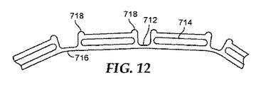
本明細書において記載される様々なアーチ部材は、歯科矯正装具に様々な機能性をもたらす他の特徴を含むことができる。例えば、図12は、アーチ部材710の概略平面図である。図1〜図4のアーチ部材20に関する設計検討及び可能性は全てが、図12のアーチ部材710に等しく当てはまる。アーチ部材710は、アーチ部材本体712、本体に接続された1つ以上のアーチ部材連結具714、及びアーチ部材本体内に配置される部分716を含む。アーチ部材710はまた、アーチ部材本体712内に配置される、突起部718を含む。1つ以上の実施形態において、各アーチ部材連結具714は、2つの突起部718を含むことができ、これらは固定具(例えば、図1〜4の固定具30)と係合し、アーチ部材が、固定具内で、選択される距離を超えて摺動するのを防ぐ。したがって、突起部718は、アーチ部材710に沿った、近心−遠心の移動を防ぐ、又は制限することができる。
The various arch members described herein can include other features that provide various functionalities to the orthodontic appliance. For example, FIG. 12 is a schematic plan view of the arch member 710. All design considerations and possibilities for the
本開示の歯科矯正装具の様々な実施形態を、任意の好適な歯科矯正治療システムと共に利用することができる。例えば、1つ以上の実施形態において、歯科矯正治療システムは、歯科矯正装具、例えば、歯科矯正装具10を含むことができる。歯科矯正装具は、アーチ部材(例えば、図1〜3のアーチ部材20)のセットを含んでもよい。各アーチ部材20は、アーチ部材本体22、及び本体に接続されたアーチ部材連結具24を含み得る。装具は、患者の歯列弓の対応する歯に接続するように適合された固定具(例えば、図1〜3の固定具30)のセットを含み得る。各固定具30は、固定具連結具34、及び固定具を歯の表面に接続するように適合された基部32を含み得る。アーチ部材連結具24は、固定具のセットの固定具30の固定具連結具34に取り外し可能に接続可能であってもよい。更に、固定具が歯の表面に接続され、アーチ部材連結具が固定具連結具に接続されるとき、固定具のセットの固定具は、アーチ部材本体に対して変位するように適合され得る。
Various embodiments of the orthodontic appliance of the present disclosure can be utilized with any suitable orthodontic treatment system. For example, in one or more embodiments, the orthodontic treatment system can include an orthodontic appliance, eg,
1つ以上の実施形態において、アーチ部材のセットの第1アーチ部材は、少なくとも1本の歯を第1構成から第2構成へと移動するように選択された形状(例えば、形状、断面形状など)を有することができる。更に、1つ以上の実施形態において、アーチ部材のセットの第2アーチ部材は、少なくとも1本の歯を第2構成から第3構成へと移動するように選択された形状(例えば、形状、断面形状など)を有することができる。 In one or more embodiments, the first arch member of the set of arch members has a shape (eg, shape, cross-sectional shape, etc.) selected to move at least one tooth from the first configuration to the second configuration. ). Further, in one or more embodiments, the second arch member of the set of arch members has a shape (eg, shape, cross-section) selected to move at least one tooth from the second configuration to the third configuration. Shape).
本明細書中に記載されるコントラスト層の種々の実施形態は、任意の好適な追加的な装具と共に利用することができる。例えば、1つ以上の実施形態において、図1〜3の歯科矯正装具10は、1つ以上のブラケット、バッカルチューブ、バンド、クリート、ボタン、取り外し可能な装具(アライナトレーを含む)、上顎拡大器、及びこれらの組み合わせと共に利用することができる。1つ以上の追加的な装具は、歯科矯正装具(例えば、図1〜3の装具10)に接続されるように適合させることができる。例えば、上顎拡大器は、任意の技術又は技術の組み合わせを使用して、歯科矯正装具に接続されるように適合させることができる。1つ以上の実施形態において、1つ以上の追加的な装具を、1つ以上の装具と同時に、しかしながら、このような装具と接続せずに、使用することができる。
Various embodiments of the contrast layer described herein can be utilized with any suitable additional appliance. For example, in one or more embodiments, the
本明細書において記載される歯科矯正装具の様々な実施形態は、例えば、米国特許出願公開第2010/0260405号(Cinader,Jr.)、及び米国仮特許出願第62/097,733号(代理人整理番号75174US002)に記載される技術など、任意の好適な技術又は技術の組み合わせを使用して、製造することができる。図1〜3の歯科矯正装具10を参照し、1つの代表的な技術は、装具10を形成するために使用され得る、患者の歯の物理的歯科模型を準備することを含む。歯科模型の構成は、治療専門家が認める目標歯列を表すことができる。本明細書で定義されるとき、「目標歯列」は、治療専門家が想定する用途に応じて、患者の現在の歯列、所望の最終的な歯列、又は予想される中間の歯列であってもよい。1つ以上の実施形態において、目標歯列はまた、1つ以上の固定具連結具の所望の構成を含み得る。
Various embodiments of orthodontic appliances described herein are described, for example, in US Patent Application Publication No. 2010/0260405 (Cinader, Jr.) and US Provisional Patent Application No. 62 / 097,733 (Attorney). Any suitable technique or combination of techniques can be used, such as the technique described in reference number 75174US002). 1-3, one exemplary technique involves preparing a physical dental model of the patient's teeth that can be used to form the
目標歯列が患者の現在の歯列として定義される場合、歯科模型は、例えば、患者の歯列のアルギネート、ポリビニルシロキサン、又はポリエーテル印象から調整されたエポキシ樹脂又は石膏鋳物により準備されてもよい。目標歯列が中間又は最終的な歯列として定義される場合、上記の鋳物を個々の模型歯要素に分割し、この歯要素を、所望の歯列を形成するように再構成してもよい。更に歯要素は、歯科模型を準備するためにワックスで固めてもよい。1つ以上の実施形態において、歯科模型は再構成可能な歯科模型であってもよく、それにより個々の歯を分割せずに再構成することができる。再構成可能な歯科模型の例は、例えば、米国特許第6,227,851号(Chishti et al.)及び同第6,394,801号(Chishti et al.)に記載されている。 If the target dentition is defined as the patient's current dentition, the dental model may be prepared, for example, with an epoxy resin or gypsum cast prepared from an alginate, polyvinylsiloxane, or polyether impression of the patient's dentition. Good. If the target dentition is defined as an intermediate or final dentition, the above casting may be divided into individual model tooth elements, which may be reconfigured to form the desired dentition . Furthermore, the tooth elements may be hardened with wax to prepare a dental model. In one or more embodiments, the dental model may be a reconfigurable dental model, whereby individual teeth can be reconfigured without splitting. Examples of reconfigurable dental models are described, for example, in US Pat. Nos. 6,227,851 (Chishti et al.) And 6,394,801 (Chishti et al.).
歯科模型は、歯科矯正装具10を作製及び構成するためのテンプレートとして使用することができる。固定具30は、歯科模型の対応する舌側及び/又は唇側の歯の表面に接続することができる。アーチ部材20は、アーチ部材連結具24が、固定具30の固定具連結具34に取り外し可能に接続可能であるようにして、任意の好適な技術又は技術の組み合わせを使用して、所望の構成に形成することができる。1つ以上の実施形態において、アーチ部材本体22は、押し出しにより形成され、その後既知の技術を使用して成形することができる。1つ以上の実施形態において、アーチ部材本体22は、基材を切断、スタンピング、又はエッチングすることによって形成することができる。1つ以上の実施形態において、アーチ部材本体22を準備するために、ポリマー材料を熱形成又はキャスティングしてもよく、1つ以上のアーチ部材連結具24は、アーチ部材本体に接続することができる。1つ以上の実施形態において、アーチ部材本体22は、3D印刷技術を使用して形成することができる。
The dental model can be used as a template for making and configuring the
一度アーチ部材本体22が形成されると、アーチ部材連結具がアーチ部材本体に接続されるように、アーチ部材連結具24はアーチ部材本体に沿って配置することができる。アーチ部材連結具24がアーチ部材本体22(例えば、図7〜8のアーチ部材本体320)と一緒に形成される1つ以上の実施形態では、アーチ部材連結具は、アーチ部材本体に1つ以上のスロットを開ける、又はエッチングすることによって形成され得る。1つ以上の実施形態において、アーチ部材20の熱形成又はキャスティングの間、アーチ部材本体22にスロットを設けることができる。
Once the
装具10を使用するために、固定具30は歯科模型から患者の歯へ移動される。固定具30の対応する歯に対する正確な位置を保存しておくために、間接結合トレー(indirect bonding tray)、又は他の移送装置を使用することができる。固定具30が、患者の歯の下側表面へとカスタマイズされ、自己位置決めする場合、直接結合も実現性のある代替法であり得る。アーチ部材20は、患者の口の中に配置され、アーチ部材連結具24を介して固定具30に取り外し可能に接続される。
To use the
仮想世界で操作を実行することにより、これらの工程の1つ以上を強化することも、又は排除さえすることも可能である。様々なデジタル技術により、装具設計の精密さが改善され、また従来手により行われていた作製プロセスの態様が容易になる可能性があり得る。 By performing operations in the virtual world, one or more of these steps can be enhanced or even eliminated. Various digital technologies may improve the precision of the orthotic design and may facilitate aspects of the fabrication process that have been performed manually.
1つの代表的な技術はデジタル走査である。デジタル口腔内走査を用いて、又は印象若しくは歯科模型をデジタル的に走査することによって、患者の歯科構造を表す仮想歯科模型を捕捉することができる。デジタル画像は、手持ち式口内スキャナ、例えば、Brontes Technologies,Inc.(Lexington,MA)によって開発され、PCT国際公開第2007/084727号(Boerjes,et al.)に記載される、能動波面サンプリングを使用する口内スキャナを使用して生成され得る。1つ以上の実施形態において、他の口腔内スキャナ又は口腔内接触プローブを使用することもできる。別の選択肢として、デジタル構造データは、患者の歯の凹型の印象を走査することによって生成され得る。更に別の選択肢として、デジタル構造データは、患者の歯の凸型の物理的模型を撮像することにより、又は患者の歯の模型上で接触プローブを使用することにより生成され得る。走査に使用されるモデルは、例えば、アルギネート又はポリビニルシロキサン(PVS)などの好適な歯科印象材から、患者の歯列の印象をキャスティングし、キャスティング材料(例えば、歯科矯正石膏又はエポキシ樹脂)を歯科印象材に注ぎ、キャスティング材料を硬化させることによって作製され得る。模型を走査するために、X線写真、レーザ走査、コンピュータ断層撮影(CT)、磁気共鳴映像法(MRI)、及び超音波画像診断を含む、任意の好適な操作技術が使用され得る。他の可能な走査方法について米国特許出願公開第2007/0031791号(Cinader et al.)に記載されている。 One representative technique is digital scanning. A virtual dental model representing the patient's dental structure can be captured using digital intraoral scanning or by digitally scanning the impression or dental model. Digital images can be obtained by hand-held mouth scanners such as Brontes Technologies, Inc. (Lexington, MA) and can be generated using an intraoral scanner using active wavefront sampling as described in PCT Publication No. 2007/084727 (Boerjes, et al.). In one or more embodiments, other intraoral scanners or intraoral contact probes can also be used. As another option, the digital structure data can be generated by scanning a concave impression of the patient's teeth. As yet another option, the digital structure data may be generated by imaging a convex physical model of the patient's teeth or by using a contact probe on the patient's tooth model. The model used for the scan casts the patient's dentition impression from a suitable dental impression material such as, for example, alginate or polyvinyl siloxane (PVS), and dental casting material (eg orthodontic plaster or epoxy resin) It can be made by pouring into an impression material and curing the casting material. Any suitable operating technique can be used to scan the model, including radiographs, laser scanning, computed tomography (CT), magnetic resonance imaging (MRI), and ultrasound imaging. Other possible scanning methods are described in US 2007/0031791 (Cinader et al.).
これにより、例えば治療専門家が、目標歯列に到達するように、コンピュータ上で仮想歯科模型を操作することが可能である。目標歯列を得るために使用され得るソフトウェア及びプロセスの更なる詳細は、例えば、米国特許第6,739,870号 (Lai et al.)、同第8,194,067号 (Raby et al.)、同第7,291,011号(Stark et al.)、同第7,354,268号 (Raby et al.)、同第7,869,983号 (Raby et al.)、及び同第7,726,968号 (Raby et al.)に開示されている。 Thereby, for example, the treatment specialist can operate the virtual dental model on the computer so as to reach the target dentition. Further details of software and processes that can be used to obtain a target dentition are described, for example, in US Pat. Nos. 6,739,870 (Lai et al.), 8,194,067 (Raby et al. ), 7,2911,011 (Stark et al.), 7,354,268 (Raby et al.), 7,869,983 (Raby et al.), And No. 7,726,968 (Raby et al.).
歯科模型の調製を容易にし得る他のデジタル技術は、ラピッドプロトタイピングである。上記の技術のいずれかを用いて仮想歯科模型を形成した後、この仮想歯科模型からラピッドプロトタイピング法により歯科模型を直接作製することができる。有利には、アルギネート印象を取ったり、又は石膏模型を鋳込む必要がない。ラピッドプロトタイピング法の例としては、3次元(3D)印刷法、選択領域レーザ積層法又は選択的レーザ焼結(SLS)法、電気泳動積層法、ロボキャスティング法、熱溶解積層法(fused deposition modeling, FDM)法、薄膜積層法(laminated object manufacturing, LOM)法、ステレオリソグラフィ(SLA)法、及びフォトステレオリソグラフィ法などが挙げられるが、これらに限定されない。走査されたデジタルデータから凸型の歯科模型を形成するこれらの、及び他の方法は、米国仮特許第8,535,580号(Cinader)に開示されている。 Another digital technique that can facilitate the preparation of dental models is rapid prototyping. After forming a virtual dental model using any of the above techniques, a dental model can be directly produced from this virtual dental model by rapid prototyping. Advantageously, it is not necessary to take an alginate impression or cast a plaster model. Examples of rapid prototyping methods include three-dimensional (3D) printing, selective area laser lamination or selective laser sintering (SLS), electrophoretic lamination, robocasting, and fused deposition modeling. , FDM) method, laminated object manufacturing (LOM) method, stereolithography (SLA) method, and photostereolithography method, but are not limited thereto. These and other methods of forming convex dental models from scanned digital data are disclosed in US Provisional Patent No. 8,535,580 (Cinader).
1つ以上の実施形態において、固定具30は、印象の採取又は口腔内走査に先立って患者の歯に接続され得る。固定具30は患者の歯に直接接着されるため、このことは、固定具を物理的歯科模型に結合する必要性、加えて固定具を患者の歯に移動する必要性を排除することによりプロセスを簡略化することができる。上記のように、不正咬合歯列から目標歯列への歯科模型の操作は、コンピュータにより行うことができる。他の潜在的な利益が存在する。例えば、固定具30と患者の歯とが口腔内走査にて一緒に捕捉される場合、固定具と患者の歯との相対位置に基づいて、ワイヤ曲げ装置又はロボットを使用してアーチ部材20をデジタル的に構成することが可能である。
In one or more embodiments, the
ラピッドプロトタイピングは、装具10を作製するための物理的歯科模型を準備する必要性をも排除し得る。ラピッドプロトタイピングが歯科模型の作製に使用できることが示された一方、ラピッドプロトタイピングを装具10の少なくとも一部分を直接的に作製するのに使用し得ることも考えられる。アーチ部材本体22、固定具30、及び連結具24、34の構成は、ラピッドプロトタイピング技術の補助により、実行することができる。直接的な作製は、装具10の作製における中間工程を排除することにより、費用及び時間を節約できる可能性がある。
Rapid prototyping may also eliminate the need to prepare a physical dental model for making the
装具10が仮想歯科模型から直接作製された場合も、物理的歯科模型は依然として、品質管理の目的で装具を確認するのに有用であり得る。これは、アーチ部材20を、物理的歯科模型に対して配置し、各アーチ部材連結具24が、対応する固定具30へと取り外し可能に接続するのを観察することによって、実行できる。装具10が適切に構成され、歯科模型が目標の歯列を表すと仮定すれば、アーチ部材20は、固定具30に取り外し可能に接続されたときに弛緩する筈である。この手順は、アーチ部材20のアーチ部材連結具24が、固定具30の対応する固定具連結具34に適切に接続できることを確実にするため、不正咬合(又は望ましくない)の歯列を表す歯科模型上の装具10を確認するのに使用することもできる。この場合は装具10は、アーチ部材20を固定具30に取り外し可能に接続する際に、アーチ部材本体22の1つ以上の部分が、力伝達係合するように機能するかたちで、作用する。
If the
1つ以上の実施形態において、装具10のアーチ部材20は、治療経過において再構成することができる。アーチ部材20、及びいくつかの実施形態において、1つ以上の固定具30を再構成することは、一連のアーチ部材を作製することの、効果的で費用効果の高い代替法となり得る。例えば、アーチ部材20は、アーチ部材本体22の1つ以上の部分に手で調整(例えば、曲げる)を行うことによって、治療経過において歯を、2つ以上の歯列を経過して誘導するよう、再構成することができる。これは、装具10を再起動するためにも有利に使用され得る。例えば、現在の装具10がもはや歯を移動するのに十分な矯正力を付与しない程、患者の歯が移動された場合、治療専門家は、アーチ部材本体22に適切な調整を行うことによって装具により適用される矯正力を回復させる自由を有する。1つ以上の実施形態において、1本以上の歯の逆戻りが予想されるときに、余分に補正する、又は補うために、このような調整が行われてもよい。任意により、口腔内走査又は他の走査技術を用いて固定具30の位置が前もって捕捉され、この情報はワイヤ曲げ装置又はロボットを使用して自動的にアーチ部材本体22を構成するのに使用することができる。
In one or more embodiments, the
1つ以上の実施形態において、少なくとも1本以上の歯、1つ以上の中間位置に関して、歯が初期不正咬合位置から最終的な目標位置へと再配置されるように、1本以上の歯に選択された矯正力をかける、漸進的な治療を行うために、一連の2つ以上のアーチ部材20を形成することができる。
In one or more embodiments, the one or more teeth may be repositioned from an initial malocclusion position to a final target position with respect to at least one or more teeth and one or more intermediate positions. A series of two or more
本明細書において記載される歯科矯正装具の様々な実施形態は、任意の好適な用途において利用することができる。一用途において、装具(例えば、図1〜3の歯科矯正装具10)は、患者の歯をその現在の位置に維持する保持具として機能する。この用途では、装具10の作製に使用される歯科模型は、患者の現在の歯科構造のレプリカである。歯科模型は患者の歯科構造と同じ構成を有するため、装具10は、口内に配置された際に、本質的にゼロ矯正力を歯に適用することになる。1つ以上の歯が逆戻りする、又は位置若しくは向きが変化した場合、装具10は、その不正な位置の歯をそれらの本来の位置に強制的に戻す。
Various embodiments of the orthodontic appliance described herein can be utilized in any suitable application. In one application, the appliance (eg,
第2の用途では、装具10は歯を現在の不正咬合位置から最終的な所望の位置へ能動的に移動するように適合され得る。より具体的には、アーチ部材本体22の1つ以上の部分は、アーチ部材連結具24が固定具連結具34に取り外し可能に接続されるときに、1つ以上の矯正力をかけるような形状であり得る。弾性アーチ部材本体22の固有の記憶は、成形された部分がその通常の構成へと弛緩するに伴い、1本以上の歯に矯正力をかけることができる。したがって、この用途では、装具10の作製に使用される歯科模型は、治療専門家により想像される最終的な歯列を表す。
In the second application, the
第3の用途では、装具10は、歯を中間の、非最終的な歯列に移動するよう構成され得る。この状況は、不正咬合の程度又は複雑さが、歯を最初の位置から最終的な位置へ再配置するのに単一の装具では不十分な場合に生じ得る。これらの場合、治療は多段階にて行われてもよく、一連の2つ以上のアーチ部材20が、固定具30の単一のセットと共に連続的に使用されて、歯を不正咬合歯列から最終的な矯正された歯列へと、漸増的かつ漸進的に移動させる。ここで、装具10の作製に使用される歯科模型は、治療過程中に観察され得る中間的な歯列を表す。
In a third application, the
第3の用途の代表的な実施形態では、第1アーチ部材20が固定具30に接続されて、患者の不正咬合の歯を中間的な歯列に再配置する。第1アーチ部材20はその後、口腔から取り外される。次いで、弛緩時の第1アーチ部材の構成とは異なる、弛緩時の構成を有する第2アーチ部材を同様に使用して、患者の歯を中間的歯列から最終的な歯列に再配置することができる。所望であれば、上記のプロセスを2つ以上の中間歯列に拡張してもよい。1つ以上の実施形態において、第1アーチ部材及び第2アーチ部材は、同じ構成を含む場合があるが、第2アーチ部材は、第1アーチ部材とは異なる材料特性を有する場合がある。例えば、第2アーチ部材の1つ以上の部分は、第1アーチ部材によりかけられる矯正力(単数又は複数)とは異なる矯正力(単数又は複数)をかける、剛性を含む場合がある。
In an exemplary embodiment of the third application, the first
中間的又は最終的な歯列を表す歯科模型は、物理的歯科鋳物を手で形成、切断及び再組立することにより作製することができる。デジタル技術を使用することもできる。例えば、最終的な歯列は、コンピュータアルゴリズム又は治療専門家からの入力により決定され、治療を一連の別個の工程に亜分割することにより、1つ以上の中間的歯列を達成することができる。1つ以上の実施形態において、中間的歯列の1つ以上が、例えば、米国特許出願第2010/0260405号(Cinader)に記載されるような、縮小された画像を含む場合がある。そのようにして中間又は最終的な歯列のそれぞれが実現されたら、対応する歯科模型はラピッドプロトタイピング法を用いて直接作製することができる。各対応する中間的、又は最終的アーチ部材20は、任意の好適な技術又は技術の組み合わせを使用して、歯科模型から作製することができる。
Dental models representing intermediate or final dentitions can be made by manually forming, cutting and reassembling physical dental castings. Digital technology can also be used. For example, the final dentition is determined by a computer algorithm or input from a treatment professional, and one or more intermediate dentitions can be achieved by subdividing the treatment into a series of separate steps. . In one or more embodiments, one or more of the intermediate dentitions may include a reduced image, as described, for example, in US Patent Application 2010/0260405 (Cinader). Once each intermediate or final dentition is thus achieved, the corresponding dental model can be made directly using rapid prototyping methods. Each corresponding intermediate or final
患者の歯の漸進的な治療を利用する1つ以上の実施形態において、任意の好適な技術又は技術の組み合わせを使用して、歯の、第2、第3、又はそれ以上の中間走査を行うことができる。次に医師又はメーカーは、1本以上の歯が、次の中間的構成、又は最終的な目標の構成へと再配置するように、歯に1つ以上の矯正力をもたらすように適合された、1つ以上の追加的なアーチ部材20をもたらすために、これらの中間的走査を利用することができる。例えば、米国特許出願公開第2010/0260405号(Cinader Jr.)、及び米国仮特許出願第62/097,733号(代理人整理番号75174US002)に記載される技術など、任意の好適な技術又は技術の組み合わせを利用して、これらの中間的な走査、模型、及びアーチ部材をもたらすことができる。
In one or more embodiments that utilize gradual treatment of the patient's teeth, any suitable technique or combination of techniques is used to perform a second, third, or more intermediate scan of the teeth. be able to. The physician or manufacturer was then adapted to provide one or more corrective forces on the teeth so that one or more teeth are repositioned to the next intermediate configuration or final target configuration. These intermediate scans can be utilized to provide one or more additional
一般的に、歯科矯正装具(例えば、図1〜3の装具10)は、提案される歯科矯正装具の仕様をもたらすことによって形成することができ、歯科矯正装具は、アーチ部材本体22、及びアーチ部材本体に接続されたアーチ部材連結具24を含む、アーチ部材20を含む。装具はまた、固定具連結具34、及び固定具を歯の表面に接続するように適合された基部32をそれぞれ含み得る、固定具30のセットを含む。各アーチ部材連結具24は、固定具連結具34に取り外し可能に接続可能であり、更に、固定具のセットの少なくとも1つの固定具30は、固定具が歯の表面に接続され、固定具連結具がアーチ部材20のアーチ部材連結具24に接続されているときに、アーチ部材本体22に対して変位するように適合される。
In general, an orthodontic appliance (eg,
歯科矯正装具10と関連する第1歯列を表す第1デジタル画像は、任意の好適な技術又は技術の組み合わせを使用して生成することができる。例えば、第1の歯列の歯を、1つ以上の所望の位置に物理的に又は仮想的に動かすことによって、目標の歯列を表す目標のデジタル画像が得られる。歯科矯正装具10の提案される仕様を、目標のデジタル画像の少なくとも一部に基づいて修正することができる。歯科矯正装具10は、目標のデジタル画像に基づいて形成することができる。
The first digital image representing the first dentition associated with the
1つ以上の実施形態において、第2歯列を表す第2デジタル画像は、任意の好適な技術又は技術の組み合わせを使用して生成することができる。第2歯列の少なくとも1本の歯は、第1歯列の対応する歯とは異なる位置にある場合がある。例えば、第1の歯列の歯を、所望の位置に物理的に又は仮想的に動かすことによって、第2の歯列を表す修正された目標のデジタル画像が得られる。歯科矯正装具10の提案される仕様を、修正された目標のデジタル画像に、少なくとも部分的に基づいて修正することができる。歯科矯正装具10は、修正された提案された仕様に基づいて修正することができる。
In one or more embodiments, the second digital image representing the second dentition can be generated using any suitable technique or combination of techniques. At least one tooth of the second dentition may be in a different position than the corresponding tooth of the first dentition. For example, by physically or virtually moving the teeth of the first dentition to a desired position, a modified target digital image representing the second dentition is obtained. The proposed specification of the
本明細書に引用される全ての参考文献及び刊行物は、それらが本開示と直接矛盾し得る場合を除き、それらの全容を参照によって本開示に明確に援用するものである。本開示の例示的実施形態を検討するとともに本開示の範囲内の可能な変形例を参照してきた。本開示のこれらの及び他の変形例及び変更例は開示の範囲から逸脱することなく当業者には明らかであろうとともに、本開示は本明細書に記載された例示的実施形態に限定されないことは理解されよう。したがって、本開示は、以下に記載の特許請求の範囲によってのみ限定されるものとする。 All references and publications cited herein are expressly incorporated herein by reference in their entirety, unless they may be in direct conflict with the present disclosure. Exemplary embodiments of the present disclosure have been discussed and reference has been made to possible variations within the scope of the present disclosure. These and other variations and modifications of the disclosure will be apparent to those skilled in the art without departing from the scope of the disclosure, and the disclosure is not limited to the exemplary embodiments described herein. Will be understood. Accordingly, the present disclosure is intended to be limited only by the scope of the following claims.
Claims (20)
固定具連結具、及び前記固定具を歯の表面に接続するように適合された基部をそれぞれ含む、複数の固定具と、を備えている歯科矯正装具であって、
各アーチ部材連結具は、前記複数の固定具のうちの固定具の前記固定具連結具に取り外し可能に接続可能であり、更に少なくとも1つの固定具は、前記アーチ部材本体に対して変位するように適合され、前記少なくとも1つの固定具は、前記固定具が前記歯の前記表面に接続され、前記複数のアーチ部材連結具のうちのアーチ部材連結具が前記固定具連結具に接続されるときに、前記アーチ部材本体に対して摺動できるようになっており、
前記アーチ部材本体は、2つのアーチ部材連結具の間において第1の形状を含み、これは別の2つのアーチ部材連結具の間の第2形状とは異なり、更に、前記アーチ部材本体は、前記複数の固定具のうちの前記固定具が前記歯の前記表面と接続されるときに、前記歯の前記表面と接触しないように適合されている、歯科矯正装具。 An arch member body, and an arch member comprising a plurality of arch member couplers connected to the arch member body;
An orthodontic appliance comprising: a fixture coupler; and a plurality of fixtures each including a base adapted to connect the fixture to a tooth surface;
Each arch member connector is removably connectable to the fixture connector of the plurality of fixtures, and at least one fixture is displaced with respect to the arch member body. And the at least one fixture is connected when the fixture is connected to the surface of the tooth and an arch member connector of the plurality of arch member connectors is connected to the fixture connector. In addition, it can slide with respect to the arch member body,
The arch member body includes a first shape between two arch member connectors, which is different from a second shape between two other arch member connectors, and the arch member body includes: An orthodontic appliance that is adapted not to contact the surface of the tooth when the fixture of the plurality of fasteners is connected to the surface of the tooth.
固定具連結具、及び前記固定具を歯の表面に接続するように適合された基部をそれぞれ含む、複数の固定具と、を備える歯科矯正装具であって、
各アーチ部材連結具は、前記複数の固定具のうちの固定具の前記固定具連結具に取り外し可能に接続可能であり、更に少なくとも1つの固定具が、前記アーチ部材本体に対して変位するように適合され、前記少なくとも1つの固定具は、前記固定具が前記歯の前記表面に接続され、前記複数のアーチ部材連結具のうちのアーチ部材連結具が前記固定具連結具に接続されるときに、前記アーチ部材本体に対して摺動できるようになっており、
各アーチ部材連結具は、接続時に前記固定具連結具を囲み、更に前記アーチ部材本体は、前記複数の固定具のうちの前記固定具が、前記歯の前記表面に接続されるときに、前記歯の前記表面と接触しないように適合されている、歯科矯正装具。 An arch member comprising a arch member body, and a plurality of arch member couplers connected to the arch member body; An orthodontic appliance comprising:
Each arch member connector is removably connectable to the fixture connector of the plurality of fixtures, and at least one fixture is displaced with respect to the arch member body. And the at least one fixture is connected when the fixture is connected to the surface of the tooth and an arch member connector of the plurality of arch member connectors is connected to the fixture connector. In addition, it can slide with respect to the arch member body,
Each arch member coupling tool surrounds the fixture coupling tool when connected, and the arch member body further includes An orthodontic appliance that is adapted not to contact the surface of the tooth.
Applications Claiming Priority (3)
| Application Number | Priority Date | Filing Date | Title |
|---|---|---|---|
| US201562133133P | 2015-03-13 | 2015-03-13 | |
| US62/133,133 | 2015-03-13 | ||
| PCT/US2016/021249 WO2016148961A1 (en) | 2015-03-13 | 2016-03-07 | Orthodontic appliance including arch member |
Publications (2)
| Publication Number | Publication Date |
|---|---|
| JP2018511383A true JP2018511383A (en) | 2018-04-26 |
| JP2018511383A5 JP2018511383A5 (en) | 2019-04-18 |
Family
ID=55538654
Family Applications (1)
| Application Number | Title | Priority Date | Filing Date |
|---|---|---|---|
| JP2017547964A Pending JP2018511383A (en) | 2015-03-13 | 2016-03-07 | Orthodontic appliance including an arch member |
Country Status (7)
| Country | Link |
|---|---|
| US (3) | US20180021108A1 (en) |
| EP (1) | EP3267925A1 (en) |
| JP (1) | JP2018511383A (en) |
| KR (1) | KR20170128376A (en) |
| CN (1) | CN107427338A (en) |
| TW (1) | TW201701842A (en) |
| WO (2) | WO2016148961A1 (en) |
Families Citing this family (41)
| Publication number | Priority date | Publication date | Assignee | Title |
|---|---|---|---|---|
| US9427291B2 (en) | 2012-10-30 | 2016-08-30 | University Of Southern California | Orthodontic appliance with snap fitted, non-sliding archwire |
| JP2018507751A (en) | 2015-03-13 | 2018-03-22 | スリーエム イノベイティブ プロパティズ カンパニー | Orthodontic apparatus including an arch member |
| US20170100215A1 (en) * | 2015-10-09 | 2017-04-13 | John H. Khouri | Orthodontic assembly |
| US11298210B2 (en) | 2015-10-09 | 2022-04-12 | John H. Khouri | Orthodontic assembly |
| US20180250099A1 (en) | 2015-11-02 | 2018-09-06 | 3M Innovative Properties Company | Orthodontic appliance having continuous shape memory |
| US11931222B2 (en) * | 2015-11-12 | 2024-03-19 | Align Technology, Inc. | Dental attachment formation structures |
| CN115153913A (en) | 2015-12-06 | 2022-10-11 | 布瑞斯技术有限公司 | Tooth repositioning system and method |
| KR20190022777A (en) | 2016-06-30 | 2019-03-06 | 쓰리엠 이노베이티브 프로퍼티즈 컴파니 | Printable compositions comprising high viscosity components and methods for producing 3D articles therefrom |
| CN110177521A (en) | 2016-12-02 | 2019-08-27 | 斯威夫特健康系统有限公司 | Indirect Orthodontic bonding system and method for bracket placement |
| US11602412B2 (en) | 2016-12-23 | 2023-03-14 | 3M Innovative Properties Company | Printable compositions including polymeric and polymerizable components, articles, and methods of making articles therefrom |
| EP4279020A3 (en) | 2017-01-31 | 2024-01-24 | Swift Health Systems Inc. | Hybrid orthodontic archwires |
| US11612458B1 (en) | 2017-03-31 | 2023-03-28 | Swift Health Systems Inc. | Method of tongue preconditioning in preparation for lingual orthodontic treatment |
| CN114129289A (en) | 2017-04-21 | 2022-03-04 | 斯威夫特健康系统有限公司 | Indirect-bonded tray, non-slip orthodontic appliance and registration system using the same |
| WO2019023009A1 (en) | 2017-07-25 | 2019-01-31 | 3M Innovative Properties Company | Photopolymerizable compositions including a urethane component and a reactive diluent, articles, and methods |
| US11904031B2 (en) | 2017-11-22 | 2024-02-20 | 3M Innovative Properties Company | Orthodontic articles comprising polymerized composition comprising at least two free-radical initiators |
| WO2019104079A1 (en) | 2017-11-22 | 2019-05-31 | 3M Innovative Properties Company | Orthodontic articles comprising polymerized composition comprising at least two free-radical initiators |
| US11389276B2 (en) | 2017-11-22 | 2022-07-19 | 3M Innovative Properties Comany | Photopolymerizable compositions including a urethane component and a monofunctional reactive diluent, articles, and methods |
| US20210386522A1 (en) | 2017-11-22 | 2021-12-16 | 3M Innovative Properties Company | Orthodontic articles comprising cured free-radically polymerizable composition comprising polymer or macromolecule with photoinitiator group |
| US11510755B2 (en) * | 2018-02-07 | 2022-11-29 | Ormco Corporation | Custom dental attachment placement appliances and appliance manufacturing methods |
| CN112512458B (en) * | 2018-05-14 | 2023-06-06 | 埃尔斯盖恩产品私人有限公司 | Orthodontic anchor assembly |
| EP3581140B1 (en) * | 2018-06-12 | 2022-01-26 | 3C | Pearl as a holding element for an orthodontic splint |
| EP3581141A1 (en) * | 2018-06-12 | 2019-12-18 | 3C | Pearl for holding an orthodontic appliance |
| EP3581146B1 (en) * | 2018-06-12 | 2022-01-26 | 3C | Pearl for orthodontic treatment |
| EP3810662A4 (en) | 2018-06-19 | 2022-05-18 | 3M Innovative Properties Company | Aqueous dispersions including polyester particles, photopolymerizable compositions, articles, and methods |
| CN112367959A (en) | 2018-06-29 | 2021-02-12 | 3M创新有限公司 | Orthodontic articles comprising cured free-radically polymerizable compositions having improved strength in aqueous environments |
| EP3813764A2 (en) | 2018-06-29 | 2021-05-05 | 3M Innovative Properties Company | Orthodontic articles prepared using a polycarbonate diol, polymerizable compositions, and methods of making the articles |
| JP7010455B2 (en) | 2018-06-29 | 2022-01-26 | スリーエム イノベイティブ プロパティズ カンパニー | Orthodontic articles prepared using polycarbonate diol and its manufacturing method |
| WO2020003197A2 (en) | 2018-06-29 | 2020-01-02 | 3M Innovative Properties Company | Orthodontic articles prepared using a polycarbonate diol, polymerizable compositions, and methods of making the articles |
| CN112105332A (en) | 2018-06-29 | 2020-12-18 | 3M创新有限公司 | Photopolymerizable compositions, articles, and methods comprising urethane methacrylate polymers prepared using polycarbonate diols |
| EP3883521A1 (en) | 2018-11-19 | 2021-09-29 | 3M Innovative Properties Company | Orthodontic articles comprising polyester urethane (meth)acrylate polymer and monofunctional (meth)acrylate monomer, methods, and polymerizable compositions |
| FR3089114B1 (en) * | 2018-12-03 | 2022-07-22 | 3C | Method of manufacturing an orthodontic device |
| US20200390524A1 (en) * | 2019-05-02 | 2020-12-17 | Brius Technologies, Inc. | Dental appliances and associated systems and methods of use |
| US20200345455A1 (en) | 2019-05-02 | 2020-11-05 | Brius Technologies, Inc. | Dental appliances and associated methods of manufacturing |
| WO2020234775A1 (en) | 2019-05-21 | 2020-11-26 | 3M Innovative Properties Company | Orthodontic articles comprising polymerized composition with pendent cyclic moieties, methods, and polymerizable compositions |
| WO2021067142A1 (en) * | 2019-09-30 | 2021-04-08 | President And Fellows Of Harvard College | Custom-designed chair-side fabricated tunnel attachments for moving teeth |
| EP4142642A1 (en) * | 2020-05-02 | 2023-03-08 | Brius Technologies, Inc. | Dental appliances and associated systems and methods of use |
| WO2022081464A1 (en) * | 2020-10-14 | 2022-04-21 | Braces On Demand Inc. | Orthodontic devices and methods of use |
| US20230355352A1 (en) | 2020-11-20 | 2023-11-09 | 3M Innovative Properties Company | Articles, methods and compositions comprising polymerizable dicarbonyl polymers |
| US11490995B2 (en) | 2021-03-25 | 2022-11-08 | Brius Technologies, Inc. | Orthodontic treatment and associated devices, systems, and methods |
| CN114343889A (en) * | 2022-02-14 | 2022-04-15 | 成都医得康科技有限公司 | Orthodontic device and manufacturing method thereof |
| WO2024079567A1 (en) | 2022-10-14 | 2024-04-18 | Solventum Intellectual Properties Company | Dental appliance, system, and method |
Family Cites Families (34)
| Publication number | Priority date | Publication date | Assignee | Title |
|---|---|---|---|---|
| US729101A (en) | 1901-03-30 | 1903-05-26 | John Stephens | Furnace for heating metal sheets. |
| US3593421A (en) * | 1967-11-15 | 1971-07-20 | Allen C Brader | Multihelical omniarch |
| US5259760A (en) * | 1991-12-07 | 1993-11-09 | Tomy K.K. | Orthodontic arch wire |
| US6095809A (en) * | 1998-09-09 | 2000-08-01 | 3M Innovative Properties Company | Orthodontic archwire having reduced stiffness |
| US6227851B1 (en) | 1998-12-04 | 2001-05-08 | Align Technology, Inc. | Manipulable dental model system for fabrication of a dental appliance |
| US6582226B2 (en) | 1999-09-27 | 2003-06-24 | 3M Innovative Properties Company | Orthodontic appliance with self-releasing latch |
| US6302688B1 (en) | 1999-09-27 | 2001-10-16 | 3M Innovative Properties Company | Orthodontic appliance with self-releasing latch |
| US6739870B2 (en) | 2001-09-26 | 2004-05-25 | 3M Innovative Properties Company | Use of finite element analysis for orthodontic mechanics and appliance selection |
| US6776614B2 (en) | 2002-02-13 | 2004-08-17 | Lingualcare, Inc. | Modular system for customized orthodontic appliances |
| US7014460B2 (en) | 2002-11-04 | 2006-03-21 | 3M Innovative Properties Company | Orthodontic appliance with fatigue-resistant archwire retaining latch |
| US7020963B2 (en) | 2003-05-02 | 2006-04-04 | 3M Innovative Properties Company | Method and apparatus for indirect bonding of orthodontic appliances |
| US8194067B2 (en) | 2004-02-04 | 2012-06-05 | 3M Innovative Properties Company | Planar guides to visually aid orthodontic appliance placement within a three-dimensional (3D) environment |
| US7252506B2 (en) * | 2004-06-10 | 2007-08-07 | 3M Innovative Properties Company | Arch member for an orthodontic brace |
| US20050277084A1 (en) | 2004-06-10 | 2005-12-15 | 3M Innovative Properties Company | Orthodontic brace with polymeric arch member |
| US7252505B2 (en) | 2004-07-28 | 2007-08-07 | 3M Innovative Properties Company | Self-ligating orthodontic appliance with post for connection to a latch |
| US7354268B2 (en) | 2004-10-06 | 2008-04-08 | 3M Innovative Properties Company | Movement of orthodontic objects along a virtual archwire within a three-dimensional (3D) environment |
| US7291011B2 (en) | 2004-10-06 | 2007-11-06 | 3M Innovative Properties Company | Placing orthodontic objects along an archwire within a three-dimensional (3D) environment |
| US20060099545A1 (en) * | 2004-11-08 | 2006-05-11 | 3M Innovative Properties Company | Methods of orthodontic treatment |
| US7869983B2 (en) | 2004-11-17 | 2011-01-11 | 3M Innovative Properties Company | Computing final occlusion with respect to torque loss in a three-dimensional virtual orthodontic system |
| US20070031774A1 (en) | 2005-08-03 | 2007-02-08 | 3M Innovative Properties Company | Registering physical and virtual tooth structures with markers |
| US20070031791A1 (en) | 2005-08-03 | 2007-02-08 | 3M Innovative Properties Company | Scanning models for digital orthodontics |
| US7819660B2 (en) * | 2005-10-26 | 2010-10-26 | Cosse Christopher C | Reusable multi-piece orthodontic appliances |
| US7840042B2 (en) | 2006-01-20 | 2010-11-23 | 3M Innovative Properties Company | Superposition for visualization of three-dimensional data acquisition |
| BRMU8600134U (en) * | 2006-01-31 | 2007-10-23 | Gilberto Vilanova Queiroz | variable prescription bracket |
| US7726968B2 (en) | 2007-03-22 | 2010-06-01 | 3M Innovative Properties Company | Methods and assemblies for making an orthodontic bonding tray using rapid prototyping |
| JP5209725B2 (en) | 2007-09-27 | 2013-06-12 | スリーエム イノベイティブ プロパティズ カンパニー | Method of digitally forming a dental model for manufacturing orthodontic craft instruments |
| WO2009085752A2 (en) | 2007-12-21 | 2009-07-09 | 3M Innovative Properties Company | Orthodontic treatment monitoring based on reduced images |
| WO2009126433A2 (en) | 2008-04-09 | 2009-10-15 | 3M Innovative Properties Company | Lingual orthodontic appliance with removable section |
| FR2950522B1 (en) * | 2009-09-25 | 2012-11-30 | Antoine Meley | ORTHODONTIC WORKING ARC AND ORTHODONTIC TREATMENT SYSTEM COMPRISING THE ARC |
| FR2972342A1 (en) * | 2011-03-11 | 2012-09-14 | Stephan Valero | Device i.e. bracket, for connecting orthodontic arch wire with tooth for correcting dental misalignments and deformities of jaws, has bonding unit detachably bonding cover with base, where cover is fastened on base plate |
| US8550814B1 (en) * | 2012-08-16 | 2013-10-08 | Monte Collins | Multi-component orthodontic bracket assembly |
| US20140255865A1 (en) * | 2013-03-11 | 2014-09-11 | Pawan Gautam | Orthodontic appliance |
| CN104546160A (en) * | 2013-10-26 | 2015-04-29 | 上海埃蒙迪材料科技股份有限公司 | Interactive orthodontic self-ligating bracket system |
| CN203763270U (en) * | 2013-12-11 | 2014-08-13 | 有研亿金新材料股份有限公司 | Orthodontic device using medical nickel titanium shape memory alloy |
-
2016
- 2016-03-07 EP EP16710609.5A patent/EP3267925A1/en not_active Withdrawn
- 2016-03-07 JP JP2017547964A patent/JP2018511383A/en active Pending
- 2016-03-07 US US15/548,474 patent/US20180021108A1/en not_active Abandoned
- 2016-03-07 WO PCT/US2016/021249 patent/WO2016148961A1/en active Application Filing
- 2016-03-07 WO PCT/US2016/021239 patent/WO2016148960A1/en active Application Filing
- 2016-03-07 CN CN201680015338.1A patent/CN107427338A/en active Pending
- 2016-03-07 KR KR1020177027285A patent/KR20170128376A/en unknown
- 2016-03-07 US US15/548,478 patent/US20180014916A1/en not_active Abandoned
- 2016-03-11 TW TW105107668A patent/TW201701842A/en unknown
-
2020
- 2020-02-24 US US16/798,684 patent/US20200188063A1/en not_active Abandoned
Also Published As
| Publication number | Publication date |
|---|---|
| US20200188063A1 (en) | 2020-06-18 |
| US20180014916A1 (en) | 2018-01-18 |
| US20180021108A1 (en) | 2018-01-25 |
| TW201701842A (en) | 2017-01-16 |
| WO2016148961A1 (en) | 2016-09-22 |
| WO2016148960A1 (en) | 2016-09-22 |
| EP3267925A1 (en) | 2018-01-17 |
| KR20170128376A (en) | 2017-11-22 |
| CN107427338A (en) | 2017-12-01 |
Similar Documents
| Publication | Publication Date | Title |
|---|---|---|
| US20200188063A1 (en) | Orthodontic appliance including arch member | |
| JP6868564B2 (en) | Orthodontic appliances including arch members | |
| US20210205049A1 (en) | Orthodontic appliances promoting coordinated movement of teeth | |
| US10335253B2 (en) | Tooth-positioning appliance for closing spaces | |
| US9925019B2 (en) | Lingual orthodontic appliance with removable section | |
| EP3267924B1 (en) | Tooth-positioning appliance for closing spaces |
Legal Events
| Date | Code | Title | Description |
|---|---|---|---|
| A521 | Written amendment |
Free format text: JAPANESE INTERMEDIATE CODE: A523 Effective date: 20190306 |
|
| A621 | Written request for application examination |
Free format text: JAPANESE INTERMEDIATE CODE: A621 Effective date: 20190306 |
|
| A977 | Report on retrieval |
Free format text: JAPANESE INTERMEDIATE CODE: A971007 Effective date: 20200206 |
|
| A131 | Notification of reasons for refusal |
Free format text: JAPANESE INTERMEDIATE CODE: A131 Effective date: 20200331 |
|
| RD03 | Notification of appointment of power of attorney |
Free format text: JAPANESE INTERMEDIATE CODE: A7423 Effective date: 20200409 |
|
| RD04 | Notification of resignation of power of attorney |
Free format text: JAPANESE INTERMEDIATE CODE: A7424 Effective date: 20200421 |
|
| A02 | Decision of refusal |
Free format text: JAPANESE INTERMEDIATE CODE: A02 Effective date: 20201027 |