JP2018508691A - Piston with cooling cavity cooling insert and method of construction - Google Patents
Piston with cooling cavity cooling insert and method of construction Download PDFInfo
- Publication number
- JP2018508691A JP2018508691A JP2017540143A JP2017540143A JP2018508691A JP 2018508691 A JP2018508691 A JP 2018508691A JP 2017540143 A JP2017540143 A JP 2017540143A JP 2017540143 A JP2017540143 A JP 2017540143A JP 2018508691 A JP2018508691 A JP 2018508691A
- Authority
- JP
- Japan
- Prior art keywords
- annular
- cooling
- piston
- forming
- combustion
- Prior art date
- Legal status (The legal status is an assumption and is not a legal conclusion. Google has not performed a legal analysis and makes no representation as to the accuracy of the status listed.)
- Ceased
Links
Images


Classifications
-
- F—MECHANICAL ENGINEERING; LIGHTING; HEATING; WEAPONS; BLASTING
- F02—COMBUSTION ENGINES; HOT-GAS OR COMBUSTION-PRODUCT ENGINE PLANTS
- F02F—CYLINDERS, PISTONS OR CASINGS, FOR COMBUSTION ENGINES; ARRANGEMENTS OF SEALINGS IN COMBUSTION ENGINES
- F02F3/00—Pistons
- F02F3/16—Pistons having cooling means
- F02F3/20—Pistons having cooling means the means being a fluid flowing through or along piston
- F02F3/22—Pistons having cooling means the means being a fluid flowing through or along piston the fluid being liquid
-
- F—MECHANICAL ENGINEERING; LIGHTING; HEATING; WEAPONS; BLASTING
- F02—COMBUSTION ENGINES; HOT-GAS OR COMBUSTION-PRODUCT ENGINE PLANTS
- F02F—CYLINDERS, PISTONS OR CASINGS, FOR COMBUSTION ENGINES; ARRANGEMENTS OF SEALINGS IN COMBUSTION ENGINES
- F02F3/00—Pistons
- F02F3/0015—Multi-part pistons
-
- F—MECHANICAL ENGINEERING; LIGHTING; HEATING; WEAPONS; BLASTING
- F02—COMBUSTION ENGINES; HOT-GAS OR COMBUSTION-PRODUCT ENGINE PLANTS
- F02F—CYLINDERS, PISTONS OR CASINGS, FOR COMBUSTION ENGINES; ARRANGEMENTS OF SEALINGS IN COMBUSTION ENGINES
- F02F3/00—Pistons
- F02F3/16—Pistons having cooling means
- F02F3/18—Pistons having cooling means the means being a liquid or solid coolant, e.g. sodium, in a closed chamber in piston
-
- F—MECHANICAL ENGINEERING; LIGHTING; HEATING; WEAPONS; BLASTING
- F02—COMBUSTION ENGINES; HOT-GAS OR COMBUSTION-PRODUCT ENGINE PLANTS
- F02F—CYLINDERS, PISTONS OR CASINGS, FOR COMBUSTION ENGINES; ARRANGEMENTS OF SEALINGS IN COMBUSTION ENGINES
- F02F3/00—Pistons
- F02F3/26—Pistons having combustion chamber in piston head
-
- F—MECHANICAL ENGINEERING; LIGHTING; HEATING; WEAPONS; BLASTING
- F02—COMBUSTION ENGINES; HOT-GAS OR COMBUSTION-PRODUCT ENGINE PLANTS
- F02F—CYLINDERS, PISTONS OR CASINGS, FOR COMBUSTION ENGINES; ARRANGEMENTS OF SEALINGS IN COMBUSTION ENGINES
- F02F3/00—Pistons
- F02F3/0015—Multi-part pistons
- F02F3/003—Multi-part pistons the parts being connected by casting, brazing, welding or clamping
- F02F2003/0061—Multi-part pistons the parts being connected by casting, brazing, welding or clamping by welding
Abstract
内燃機関のピストンおよびその構成方法を提供する。ピストンは、上部および下部を有する。上部は、燃焼ボウルが凹設された上面を含む上部燃焼表面を有する。上面と燃焼ボウルの側壁との間に環状の燃焼ボウルリムが延在する。下部は、底壁、および底壁から垂下するピンボスの対を有する。上部は、上部と下部との間に環状の冷却空洞が規定されるように、下部に固定される。燃焼ボウルの側壁は、冷却空洞の一部の境界を定める半径方向外向きに向いた面を有し、半径方向外向きに向いた面には、前記燃焼ボウルリムに隣接する環状の凹んだくぼみが形成されている。環状くぼみに冷却リングが配置されている。冷却リングは、燃焼ボウルリムの冷却を容易にするために、燃焼ボウルリムに隣接するように冷却液を通している。A piston for an internal combustion engine and a method for configuring the same are provided. The piston has an upper part and a lower part. The upper portion has an upper combustion surface including an upper surface with a combustion bowl recessed. An annular combustion bowl rim extends between the top surface and the side wall of the combustion bowl. The lower part has a bottom wall and a pair of pin bosses depending from the bottom wall. The upper part is fixed to the lower part so that an annular cooling cavity is defined between the upper part and the lower part. The side wall of the combustion bowl has a radially outwardly facing surface that delimits a portion of the cooling cavity, the radially outwardly facing surface having an annular recessed recess adjacent to the combustion bowl rim. Is formed. A cooling ring is arranged in the annular recess. The cooling ring passes coolant adjacent to the combustion bowl rim to facilitate cooling of the combustion bowl rim.
Description
関連出願の相互参照
本願は、2015年1月30日に出願された米国仮出願第62/110,083号および2016年2月1日に出願された米国実用特許出願第15/011,784号の利益を主張するものであり、それらのすべての記載内容を、引用により本明細書に援用する。
This application is related to US Provisional Application No. 62 / 110,083 filed on January 30, 2015 and US Utility Patent Application No. 15 / 011,784 filed on February 1, 2016. The entire content of which is incorporated herein by reference.
発明の背景
1.発明の分野
本発明は、全体として、内燃機関に関し、より具体的には、内燃機関において使用されるピストンに関する。
BACKGROUND OF THE INVENTION The present invention relates generally to internal combustion engines, and more specifically to pistons used in internal combustion engines.
2.従来技術
内燃機関メーカーは、機関性能および燃費を改善する方法を常に探求している。燃費を改善するために、機関メーカーは、たとえば、オイルポンプのサイズを小さくしてもよいが、そうすると、ピストンに供給される冷却油の量が減少し得る。これによって、ピストンまたは少なくともピストンの一部、つまり、使用中のピストンの最も熱い領域のうちの一つであると知られている燃焼ボウルリムの過熱を招き得る。シリンダボア内の圧縮荷重および温度を上昇させることによって、性能と燃費の両方を改善できるが、ピストンは、特に、潜在的にオイルが不足した環境では、このような荷重および温度に確実に対応できなければならない。
2. Prior art Internal combustion engine manufacturers are constantly seeking ways to improve engine performance and fuel economy. To improve fuel economy, engine manufacturers may, for example, reduce the size of the oil pump, but doing so can reduce the amount of cooling oil supplied to the piston. This can lead to overheating of the piston or at least a portion of the piston, i.e. the combustion bowl rim known to be one of the hottest areas of the piston in use. Increasing the compression load and temperature in the cylinder bore can improve both performance and fuel economy, but the piston must be able to reliably handle such loads and temperatures, especially in potentially oil-poor environments. I must.
通常、ピストンの天壁、特に、燃焼ボウルのへりまたはリムでの動作温度は、ピストンの領域の中で最も高い。これは、隣接する燃焼ボウル内で燃焼が起こり、リムは、通常、半径方向内向きに突出したやや尖ったへりに相当し、燃焼の熱に対して比較的高いS/V比を示すため、周囲に比べて急速に加熱されやすいためである。 Usually, the operating temperature at the top wall of the piston, in particular at the edge or rim of the combustion bowl, is the highest in the region of the piston. This is because combustion occurs in adjacent combustion bowls, and the rim usually corresponds to a slightly pointed edge protruding radially inward and exhibits a relatively high S / V ratio to the heat of combustion. It is because it is easy to be heated rapidly compared with the surroundings.
発明の概要
内燃機関のピストンを提供する。ピストンは、上部および下部を含んだピストン本体を有する。上部は、シリンダボア内の燃焼ガスに直接晒されるように構成された上部燃焼表面を有する。上部燃焼表面は、燃焼ボウルが凹設された上面を有する。燃焼ボウルは、床、および上面に向かって上方向に延在する環状の側壁を有する。上面と側壁との間に環状の燃焼ボウルリムが延在している。下部は、底壁および底壁から垂下するピンボスの対を有し、ピンボスは、軸方向一直線に並んだピンボアを有し、底壁はオイル・インレットを有する。上部は、上部と下部との間に環状の冷却空洞が形成されるように、下部に固定されている。底壁は、冷却空洞内へ延在するオイル・インレットを有する冷却空洞の一部を形成する。側壁は、冷却空洞の一部の境界を定める半径方向外向きに向いた面を有し、半径方向外向きに向いた面には、燃焼ボウルリムに隣接する環状の凹んだくぼみが形成されている。環状くぼみに冷却リングが配置されている。冷却リングは、燃焼ボウルリムの冷却を容易にするために、燃焼ボウルリムに隣接する内部の冷却液を宙に浮かせて通すように構成されている。
SUMMARY OF THE INVENTION A piston for an internal combustion engine is provided. The piston has a piston body including an upper part and a lower part. The upper portion has an upper combustion surface configured to be directly exposed to the combustion gas in the cylinder bore. The upper combustion surface has an upper surface with a combustion bowl recessed. The combustion bowl has a floor and an annular side wall extending upwardly toward the top surface. An annular combustion bowl rim extends between the top surface and the side wall. The lower part has a bottom wall and a pair of pin bosses depending from the bottom wall, the pin bosses have pin bores aligned in the axial direction, and the bottom wall has an oil inlet. The upper part is fixed to the lower part so that an annular cooling cavity is formed between the upper part and the lower part. The bottom wall forms part of the cooling cavity with an oil inlet that extends into the cooling cavity. The sidewall has a radially outwardly facing surface that delimits a portion of the cooling cavity, and the radially outwardly facing surface is formed with an annular recessed recess adjacent to the combustion bowl rim. . A cooling ring is arranged in the annular recess. The cooling ring is configured to float and allow the internal coolant adjacent to the combustion bowl rim to float in order to facilitate cooling of the combustion bowl rim.
本発明の別の態様によれば、冷却リングは、環状くぼみへのばね付勢された嵌め込みにぱちんと留められている。 According to another aspect of the invention, the cooling ring is snapped into a spring-loaded fit into the annular recess.
本発明の別の態様によれば、冷却リングは、ばね付勢によって互いに離れた、向かい合った自由端を有する。 According to another aspect of the invention, the cooling ring has opposing free ends that are separated from each other by spring bias.
本発明の別の態様によれば、冷却リングは、オイルを半径方向外向きに面した側壁に直接接触させることによって燃焼ボウルリムの冷却をさらに容易にするために、横断面を見たときに円周方向に不連続な壁を有することができる。 According to another aspect of the invention, the cooling ring is circular when viewed in cross-section to further facilitate cooling of the combustion bowl rim by bringing oil into direct contact with the radially outwardly facing side walls. It can have discontinuous walls in the circumferential direction.
本発明の別の態様によれば、壁は、環状の隙間によって互いに離れた弧状の自由端を含むことができ、環状の隙間は、燃焼ボウルリムの冷却を容易にするために、環状くぼみに面し、弧状の自由端は、冷却リング内にオイルを含めることを容易にするために、環状くぼみに接している。これによって、燃焼ボウルリムの領域内のオイルの冷却効果がさらに高められる。 In accordance with another aspect of the present invention, the wall can include arcuate free ends separated from each other by an annular gap that faces the annular recess to facilitate cooling of the combustion bowl rim. However, the arcuate free end is in contact with the annular recess to facilitate the inclusion of oil in the cooling ring. This further enhances the cooling effect of the oil in the region of the combustion bowl rim.
本発明の別の態様によれば、冷却リング内全体の連続した、新鮮なオイル供給を循環させることを容易にするために、向かい合った自由端は、オイルが前記冷却リングから外に向かって流れられるように開口したままにできる。これによって、燃焼ボウルリムの領域内のオイルの冷却効果がさらに高められる。 According to another aspect of the present invention, in order to facilitate the circulation of a continuous, fresh oil supply throughout the cooling ring, the opposed free ends allow oil to flow outwardly from the cooling ring. Can be left open as This further enhances the cooling effect of the oil in the region of the combustion bowl rim.
本発明の別の態様によれば、冷却リング内へのオイルの新鮮な供給を導くことを容易にするために、冷却リングの壁は、底壁のオイル・インレットと軸方向一直線に並んだオイル吸い込み穴を有することができる。これによって、燃焼ボウルリムの領域内のオイルの冷却効果がさらに高められる。 According to another aspect of the present invention, the cooling ring wall is axially aligned with the bottom wall oil inlet to facilitate directing a fresh supply of oil into the cooling ring. Can have suction holes. This further enhances the cooling effect of the oil in the region of the combustion bowl rim.
本発明の別の態様によれば、冷却リングは、横断面を見たときに円周方向に連続的な壁を有することができる。 According to another aspect of the invention, the cooling ring can have a continuous wall in the circumferential direction when viewed in cross section.
本発明の別の態様によれば、冷却リングは、内部に冷却媒体を封止することができる。
本発明の別の態様によれば、内燃機関のピストンを構成する方法が提供される。方法は、シリンダボア内の燃焼ガスに直接晒されるように構成された上部燃焼表面を有する上部を形成するステップを備え、上部の形成ステップは、上面および上面に凹設された燃焼ボウルを有する上部燃焼表面を形成するステップと、床、および上面に向かって上方向に延在する環状の側壁を有する燃焼ボウルを形成するステップと、上面と側壁との間に延在する環状の燃焼ボウルリムを形成するステップと、冷却空洞の上部分を規定するために半径方向に互いに離れた環状の上部外側カラーと環状の上部内側カラーとを有する上部を形成するステップと、冷却空洞の上部分に、燃焼ボウルリムと隣接する環状くぼみを形成するステップとを含み、方法は、さらに、底壁および底壁から垂下するピンボスの対を有する下部を形成するステップを含み、下部の形成ステップは、軸方向一直線に並んだピンボアを有するピンボスを形成するステップと、オイル・インレットを有する底壁を形成するステップとを含み、方法は、さらに、環状くぼみに冷却リングを配置するステップと、上部と下部との間に環状の冷却空洞を形成するように下部に上部を固定するステップとを含む。
According to another aspect of the present invention, the cooling ring can seal the cooling medium inside.
In accordance with another aspect of the present invention, a method for configuring a piston of an internal combustion engine is provided. The method comprises forming an upper portion having an upper combustion surface configured to be directly exposed to combustion gases in a cylinder bore, the upper formation step comprising an upper combustion having an upper surface and a combustion bowl recessed in the upper surface. Forming a combustion bowl having a surface, a floor and an annular side wall extending upwardly toward the top surface, and forming an annular combustion bowl rim extending between the top surface and the side wall Forming an upper portion having an annular upper outer collar and an annular upper inner collar that are radially spaced apart from each other to define an upper portion of the cooling cavity; and a combustion bowl rim on the upper portion of the cooling cavity; The method further includes forming a bottom wall having a bottom wall and a pair of pin bosses depending from the bottom wall. The lower forming step includes forming a pin boss having an axially aligned pin bore and forming a bottom wall having an oil inlet, and the method further includes a cooling ring in the annular recess. And fixing the upper part to the lower part so as to form an annular cooling cavity between the upper part and the lower part.
本発明の別の態様によれば、方法は、さらに、環状くぼみへのばね付勢された嵌め込みに冷却リングをぱちんと留めるステップを含む。これによって、製造の容易性を改善する。 According to another aspect of the present invention, the method further includes snapping the cooling ring into a spring-loaded fit into the annular recess. This improves the ease of manufacture.
本発明の別の態様によれば、方法は、さらに、環状くぼみへのばね付勢された嵌め込みをもたらすために、冷却リングの向かい合った自由端を互いに離れるように開くステップを含む。 According to another aspect of the present invention, the method further includes opening the opposed free ends of the cooling rings away from each other to provide a spring-loaded fit into the annular recess.
本発明の別の態様によれば、方法は、さらに、横断面を見たときに円周方向に不連続な壁を有する冷却リングを形成するステップを含む。 According to another aspect of the invention, the method further includes forming a cooling ring having walls that are circumferentially discontinuous when viewed in cross section.
本発明の別の態様によれば、方法は、さらに、環状の隙間によって互いに離れている弧状の自由端を有する壁を形成するステップと、弧状の自由端が環状くぼみに当接した状態で、環状くぼみに面するように環状の隙間を向けるステップとを含む。 According to another aspect of the invention, the method further comprises the steps of forming walls having arcuate free ends separated from each other by an annular gap, wherein the arcuate free ends abut the annular recess. Directing an annular gap to face the annular recess.
本発明の別の態様によれば、方法は、さらに、オイルが冷却リングから外に向かって流れられるように開口した向かい合った自由端を形成するステップを含む。 According to another aspect of the present invention, the method further includes forming opposed free ends that are open to allow oil to flow outwardly from the cooling ring.
本発明の別の態様によれば、方法は、さらに、壁にオイル吸い込み穴を形成するステップと、オイル吸い込み穴を底壁のオイル・インレットと軸方向一直線に並べるステップとを含む。 According to another aspect of the invention, the method further includes forming an oil suction hole in the wall and aligning the oil suction hole with an oil inlet in the bottom wall in an axial alignment.
本発明の別の態様によれば、方法は、さらに、横断面を見たときに円周方向に連続的な壁を有する冷却リングを形成するステップを含む。 According to another aspect of the invention, the method further includes forming a cooling ring having a circumferentially continuous wall when viewed in cross section.
本発明の別の態様によれば、方法は、さらに、冷却媒体を冷却リング内に封止するステップを含む。 According to another aspect of the invention, the method further includes sealing a cooling medium within the cooling ring.
本発明のこれらのおよびその他の態様、特徴、および利点は、以下の詳細な説明、および添付図面を踏まえて考慮するとより容易に理解されるであろう。 These and other aspects, features and advantages of the present invention will be more readily understood in view of the following detailed description and accompanying drawings.
現在好ましい実施の形態の詳細な説明
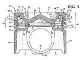
図面をより詳細に参照すると、図1は、たとえば、最近の小型で高性能な車両エンジンなどの内燃(IC)機関のシリンダボアまたはチャンバ(図示せず)での往復運動のための、本発明の一実施の形態に従って構成されるピストン10の部分断面図を示す。ピストン10は、ピストンが使用中に往復する長手方向の中心軸14に沿って延在する本体12を備える。本体12は、上部クラウン(上側部や上部16とも称される)および下部クラウン(下側部や下部18とも称される)を有する。上部クラウンと下部クラウンとは、ヘッド領域20内で互いに接合されている。上部16および下部18は、まず、鋳造、鍛造、または機械加工法などにおいて別々の材料として製造され、次に、互いに接合される。その結果、上部16と下部18との間に内部の環状外部オイル冷却空洞22が形成される。内部の環状外部オイル冷却空洞22には、ピストンヘッド領域20の冷却を容易にするためのオイルが流れる。上部16と下部18とは、これらに限定されないが、誘導圧接、摩擦圧接、ろう付け接合、電荷担体粒子、レーザー、または抵抗溶接などのさまざまな種類の溶接方法によって互いに接合されてもよい。さらには、例示の実施の形態は溶接継手を利用して下部18に上部16を接合しているが、本明細書において、上部16と下部18とは、一例として、しかしこれに限定されず、接着やメカニカルファスナーなど、その他の固着方法および機構によって互いに接合されてもよいと考えられる。本明細書において、「上/天」、「下/底」、「上側/上部」、および「下側/下部」の表す内容は、使用中に往復運動する中心軸14に沿って向きをつけられたピストン10と比較したものであることがわかるだろう。これは、便宜上であって、限定ではない。ピストン10は、角度を付けられてもよいし、略直立以外の状態に取り付けられて動作してもよい場合があり得るためである。本発明の一態様によると、ピストン10の燃焼ボウルリム26として知られる、ピストンヘッド領域20の最も熱い部分の冷却を容易にするために、冷却空洞冷却インサートリング(以下、単に冷却リング24と称する)が冷却空洞22内に配置される。
Detailed Description of Presently Preferred Embodiments Referring to the drawings in more detail, FIG. 1 shows a cylinder bore or chamber (not shown) of an internal combustion (IC) engine, such as, for example, a modern compact high performance vehicle engine. FIG. 2 shows a partial cross-sectional view of a
ピストン10の上部16は、上部燃焼表面28を有する。上部燃焼表面28は、環状上面30より下に凹んだ燃焼ボウル32を囲む実質的に平らな一番上の環状上面30を含む。燃焼ボウル32は、床34含む。床34は、上部燃焼表面と下面(クラウン下面としても知られる)との間に延びる均一または一定の厚さを有してもよい。例示の実施の形態の床34は均一な厚さを有するが、本明細書において考えられるその他の実施の形態の床34は、上部燃焼表面と下面との間に変動する厚さを有してもよいということが理解されるだろう。床34の上部燃焼表面は傾斜があり、「メキシカン・ハット」と称される場合もあり、ピストン10の中心軸14上に同軸状に配置される中央の頂部36を設ける。本明細書において考えられるその他の実施の形態において、中央の頂部36は、中心軸14から半径方向にずれていてもよいことが了解されるはずである。燃焼ボウル32の床34は、頂部36を囲んで燃焼ボウル32の一番下側部分を形成する環状の谷部38を設ける。床34の底面またはクラウン下面は、燃焼ボウル32の上部燃焼表面の輪郭をなぞっている、または実質的になぞっており、頂部36の直下に隆起した下部頂部40を設ける。下部頂部40は、コンロッド(図示せず)の小端部を収容するように構成される。
The
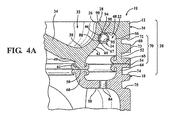
上部18の燃焼ボウル32は、燃焼ボウル床34を囲んで燃焼ボウル床34から上方向に延在する環状の側壁42を含む。側壁42は、谷部38に隣接しており、谷部38から上面30に上方向に延在するように位置し、環状の燃焼ボウルリム26は、側壁42を上面30に遷移させる。燃焼ボウルリム26は、側壁42から半径方向内向きに延在するように形成でき、必要であれば、側壁42内に下部をくり抜いた環状凹入の空隙を設けることができる。図4に最もよく示すように、燃焼ボウル32の側壁42の反対側の、半径方向外向きに向いた面は、冷却空洞22の内側面44の一部を形成する。内側面44は、燃焼ボウルリム26に隣接する燃焼ボウル32を囲む環状凹部またはくぼみ46を有し、冷却空洞22の一番上の内側面48のすぐ隣に示されている。環状くぼみ46は、冷却リング24をばね付勢でぱちんと嵌めるように構成されており、冷却リング24をぱちんと嵌めるのを助長する環状の下部リップ47を有する。
The upper 18
ピストン10の上部16は、さらに、谷部38に隣接する燃焼ボウル32の床34の下面から上部内側の接合面50まで垂下する少なくとも一つの上部内側の環状接合リブまたはカラー49を含む。また、上部24は、上面30から上部外側の接合面54まで垂下する上部外側の環状接合リブまたはカラー52も含み、上部外側の環状カラー52と上部内側の環状カラー49とは、冷却空洞22の環状の上部分56によって、半径方向に互いに離れている。
The
ピストン10の下部18は、冷却空洞22の床を形成する環状の床(以下、底壁58と称する)を含む。ピストン10の上部16と接合されると、底壁58は、底壁58から下部内側の接合面61まで上方向に延在する下部内側の環状接合リブまたはカラー60によって、側壁42の半径方向内向きの燃焼ボウル32の床34と一体になる。また、下部26は、底壁58から下部外側の接合面65まで上方向に延在する下部外側の環状接合リブまたはカラー64も含み、下部外側の環状カラー64と下部内側の環状カラー60とは、冷却空洞22の環状の下側部分66によって、半径方向に互いに離れている。
The
下部18の下部外側の環状カラー62と上部16の上部外側の環状カラー52とによって、上面30から下方向に延在する環状の外側壁68が形成される。外側壁68に環状のリングベルト領域70が形成されており、複数の環状のリング溝72、73、74が、ピストンリング(図示せず)を嵌めるためのリングベルト領域70内に形成されている。例示的な実施の形態において、リング溝72、73、74は、コンプレッションリング(図示せず)を嵌めるための、上面30に隣接する一番上のリング溝72と、油かき中間リング(図示せず)を嵌めるための、一番上のリング溝72の下に配置された中間リング溝73と、一番下のオイルリング(図示せず)を嵌めるための、中間リング溝73の下に配置された一番下のリング溝74とを含む。一番下のリング溝74の下には、軽量化のため、およびオイルを収集してピストン10の下部18に迂回させて油受に戻すためのオイル排出溝75が形成されている。本発明の例示的な実施の形態は、3つのリング溝72、73、74を含むが、本発明のその他の実施の形態は、任意の数のリング溝を含んでもよい。
The lower outer annular collar 62 of the
ピストン10の下部18は、さらに、底壁58から垂下するスカートパネル76の対を含む。スカートパネル76は、その長手方向に延在する側に沿って、ストラット部79によって、ピンボス78の対に直接接合されており、ピンボス78は、横方向に離れたピンボア80の対を設ける。図2に最もよく示すように、ピンボア80は、中心軸14に対して横方向に延在するピンボア軸82上で同軸状に互いに離れている。スカートパネル76は、ピンボス78の反対側を跨いで概ね正反対の位置に配置されている。スカートパネル76は、凸状の外側面を含む。凸状の外側面は、シリンダボアを貫いて往復運動するときのピストン10を所望の向きに維持するために、シリンダボアの面と合わさるための起伏がついている。
The
下部18の底壁58は、上面30から軸方向に離れて軸上に一直線に並んでおり、リングベルト領域70の外側壁68は、ピストン10のヘッド領域20内に環状のオイル冷却空洞22を形成するために、燃焼ボウル32の側壁42から半径方向外向きに離れている。例示的な実施の形態のオイル冷却空洞22は、環状トロイド形状のチャンバである。しかしながら、オイル冷却空洞22は、燃焼ボウル32および底壁58の相対的な輪郭によって決まる所望の形状に形成されてもよいことが了解されるはずである。底壁58は、ピストン10の下部分に向かって開口したオイル・インレット84を形成する少なくとも一つの貫通孔を含む。クランク・サンプ供給元(たとえば、機関のオイルジェット)からのオイルの連続的な流れまたはストリームを導くために、オイル・インレット84は、オイル冷却空洞22と直接に流体連通している。また、底壁58は、少なくとも、ピストン10が往復運動する間の冷却空洞22全体にわたるオイルの連続的な流れを容易にするオイル・アウトレット86を形成する貫通孔を含んでもよい。油受からのオイルがオイル・インレット84からオイル冷却空洞に流れ込み、オイル・アウトレット86を通ってオイル冷却空洞から流出するようにオイルの流れの流体動力がもたらされることがわかるはずである。
The
冷却リング24は、ヘッド領域20のリム26および上面30の冷却を容易にするために、上面30および燃焼ボウルリム26に隣接するオイル冷却空洞22の上部領域に固定される。冷却リング24は、環状くぼみ46内で、燃焼ボウル32の側壁42の周囲を環状に延在し、半径方向外向きに延在する、くぼみ46の下部リップ47は、冷却リング24の半径方向内向きにかかるばね付勢によって生じる締り嵌めによって冷却リング24をくぼみ46に維持する。例示的な実施の形態において、冷却リング24は、円周方向に延在する不連続な壁88を有し、横断面を見たときに、一例として、しかしこれに限定されず、壁88の横断面は略C字形、U字形、またはV字形である。このように、図4に最もよく示すように、壁88は、冷却リング24の向かい合った自由端92、93(図5)の間に環状に延在する弧状の自由端90を有する。自由端92、93は、環状くぼみ46に面するように向きをつけられた環状の隙間94によって互いに離れており、オイルに環状の隙間94を自由に流れさせて側壁42および/または冷却空洞22の一番上の面48と流体接触させる。したがって、環状くぼみ46の側壁内側面44および/または冷却空洞22の一番上の面48と当接している自由端92、93によって、冷却リング24を流れるオイルが隙間94を流れて内側面44、48と直接接触できるようになり、上面30を形成する側壁42の一番上の壁から直接熱を伝導する。これによって、すぐ隣の燃焼ボウルリム26および上面30の動作温度を抑える。オイルの冷却リング24内への進入を容易にするために、壁88は、底壁58のオイル・インレット84と軸上に一直線に並ぶように構成された吸い込み穴95(図4Aおよび図5に最もよく示すように)を有する。したがって、噴霧となってオイル・インレット84に流入したオイルの少なくとも一部は、吸い込み穴95から冷却インサートリング24内に噴霧となって直接流入できる。
The
冷却空洞リング24は、実質的に閉じられた環状構成になるようにあらかじめ形成されており、凹んだ環状くぼみ46にしっかりと、またはぱちんと留められる大きさに環状に作られている。冷却リング24をぱちんと嵌めることによって、ばね付勢を受けた自由端92、93が互いにわずかに離れるように開いて、半径方向内向きのクランプ・ばね力を生み出す。半径方向内向きのクランプ・ばね力は、冷却リング24を自動的にくぼみ46に保持し、使用中にピストン10が往復運動する間の冷却リング24とピストン本体12との間の相対的運動を防止する。ばね付勢力は、冷却リング24が曲がることによって、あるいは所定の閉じられたまたは実質的に閉じられた環状に冷却リング24が作られた結果達成されることがわかるはずである。環は、下部リップ47の外径より小さい所定の内径、好ましくは、環状くぼみ46の谷部の外径よりも少なくともわずかに小さい所定の内径を有する。ばね付勢を容易にするように作用する自由端92、93に加えて、開口した自由端によって、オイルが冷却リング24から自由に流れ出ることができる出口穴96が形成される。吸い込み穴95と出口穴96とは、本明細書においてわずかな角度のずれは考えられるが、概ね正反対の位置に構成される。これによって、実質的に燃焼ボウルリム26全体の周囲を流れるオイルが、燃焼ボウルリム26に最適な冷却をもたらすことを容易にする。
The
2つの部品16、18を使って例示的な実施の形態のピストン10が製造される結果、上部16を下部18に接合する前に冷却リング24が上部16にしっかりと、またはぱちんと留められてもよいことが理解され得る。例示的な実施の形態の空洞冷却リング24は、有利には、所定の位置に鋳造されなくても、ピストン10に取り付けられる。そのため、本発明の一態様に係るピストン10の製造は、鋳造の場合、簡略化される。空洞冷却リング24は例示的な実施の形態のくぼみ46にしっかりと、またはぱちんと留められているが、その他の実施の形態は、これらに限定されないが、コールド・スプレー溶接、タック溶接、抵抗溶接を含むさまざまな種類の溶接方法を使った溶接、およびさまざまな種類の金属部品接着剤を用いた接着を含むさまざまなその他の方法、またはメカニカルファスナーによって取り付けられる空洞冷却リング24を備えてもよいことが了解されるだろう。
As a result of manufacturing the
このことから、冷却リング24内を流れるオイルは、冷却を必要とするピストン10の範囲、つまり、ピストン10の燃焼ボウルリム26および上部燃焼表面28に、より素早く、直接的に、そして効率よく分布され得ることがわかるはずである。冷却リング24がなければ、燃焼ボウルリム26および上部燃焼表面28に最も近い冷却空洞22の上部領域内へのオイルの分布が不十分になるおそれがあり、これらの範囲に達したオイルは、燃焼ボウルリム26および上部燃焼表面28との冷却接触状態を維持しない。このように、空洞冷却リング24は、対照的に、冷却を最も必要とする範囲(つまり、燃焼ボウルリム26および上部燃焼表面28)における冷却空洞22の上部領域にオイルを長時間保持できるので、これらの領域から絶えず熱を取り除く。
From this, the oil flowing in the
例示的な実施の形態の空洞冷却リング24は、これらに限定されないが、銅やアルミニウムなど、最適な伝導伝熱をもたらすための高い熱伝導性を有する材料から構成されることが好ましい。燃焼ボウルリム26は、ピストン10の頂面のその他の領域と比べて、約150℃〜200℃高くなり得ることが知られている。しかしながら、機関作動中の燃焼ボウルリム26の温度が、約520℃を確実に下回ることが通常望ましい。燃焼ボウルリム26をより低い温度にすることによって、機関メーカーは、冷却リング24が設けられている結果、上部燃焼表面28および燃焼ボウルリム26からの伝熱が増加しているおかげで、たとえば、オイルポンプのサイズを小さくすることができるだろう。オイルポンプのサイズを小さくすることは、ピストン10が作動する内燃機関の燃料効率の増加につながり得る。
The
例示的な実施の形態は、上述したように、一例として、しかしこれに限定されず、略C字形、U字形、またはV字形である、円周方向に不連続な形状を有する空洞冷却リング24を備えるが、空洞冷却リング124は、図4Aに示すように、丸いまたは円形の断面を有する筒状など、横断面を見たときに代替の形状を有し得ることがわかるだろう。インサートは、これらに限定されないが、正方形または長方形の断面を有する管など、丸型以外の形をとってもよいことがさらに了解されるはずである。冷却リング124は、図5に示すように、下から見たときに冷却リング24と全く同じ外観であるため、図の複製は必要ないと思われる。冷却リング124は、上に示し述べたような吸い込み穴195と、上述と同様に構成された向かい合った自由端192、193とを有する。これによって、出口穴196が設けられ、自由端192、193はわずかに互いに離れ、環状くぼみ46内でばねクリップ取り付けができるようになる。このように、円周方向に連続的な壁188を有していることを除いて、冷却リング124は上述したものと同じであるため、これ以上の説明は必要ないと思われる。
The exemplary embodiment is, as described above, by way of example but not limitation, a
本発明のさらに別の態様によると、図5Aに示すように、本発明の別の態様に従って構成される冷却リング224は、不活性ガス(たとえば、アルゴン)および/または冷却液のような代替の冷却媒体を含んだ状態で封止されてもよい。冷却媒体は、個体物質であってもよい。代替の冷却媒体は、ピストン10へ取り付ける前の冷却リング224内に簡単に封止でき、ピストン10の寿命の間に冷却リング224内で活性を維持するように構成されていてもよく、または時間が経つにつれて消耗または分解するように構成されてもよい。当然、封止された冷却リング224は、上述したような吸い込み穴や出口穴を有しないが、自由端292、293を有することができる。自由端292、293は、所望の冷却媒体が冷却リング224内に気密密閉されている限り、冷却媒体を冷却リング224内に配置する際などに、密封材、エンドプラグの締付け、またはそれらの任意の組み合わせを含む任意の適した封止機構によって密封される。そうでない場合、冷却リングは、上述したように、環状くぼみ46内に取り付けられる。
According to yet another aspect of the present invention, as shown in FIG. 5A, a
上記教示に鑑みて、本発明の多くの変更例および変形例が可能であることは明らかである。そのため、本発明は、請求の範囲内であれば、具体的に記載されて示されている以外の態様で実施されてもよいことが了解されるだろう。 Obviously, many modifications and variations of the present invention are possible in light of the above teachings. Thus, it will be appreciated that the invention may be practiced otherwise than as specifically described and illustrated within the scope of the claims.
Claims (25)
上部および下部を含むピストン本体を備え、前記上部は、シリンダボア内の燃焼ガスに直接晒されるように構成された上部燃焼表面を有し、前記上部燃焼表面は、上面および前記上面に凹設された燃焼ボウルを有し、前記燃焼ボウルは、床、および前記上面に向かって上方向に延在する環状の側壁を有し、前記上面と前記側壁との間に環状の燃焼ボウルリムが延在し、
前記下部は、底壁および前記底壁から垂下するピンボスの対を有し、前記ピンボスは、軸方向一直線に並んだピンボアを有し、前記底壁はオイル・インレットを有し、
前記上部は、前記上部と前記下部との間に環状の冷却空洞が形成されるように、前記下部に固定され、前記底壁は、前記冷却空洞内へ延在する前記オイル・インレットと共に、前記冷却空洞の一部を形成し、前記側壁は、前記冷却空洞の一部の境界を定める半径方向外向きに向いた面を有し、前記半径方向外向きに向いた面には、前記燃焼ボウルリムに隣接する環状の凹んだくぼみが形成されており、
前記ピストンは、さらに、
前記環状くぼみに配置された冷却リングを備え、前記冷却リングは、その内部に、前記燃焼ボウルリムに隣接するように冷却液を通すように構成されている、ピストン。 A piston of an internal combustion engine,
A piston body including an upper portion and a lower portion, the upper portion having an upper combustion surface configured to be directly exposed to combustion gas in a cylinder bore, the upper combustion surface being recessed in the upper surface and the upper surface A combustion bowl, the combustion bowl having a floor and an annular side wall extending upwardly toward the top surface, an annular combustion bowl rim extending between the top surface and the side wall;
The lower portion has a bottom wall and a pair of pin bosses depending from the bottom wall, the pin boss has an axially aligned pin bore, and the bottom wall has an oil inlet,
The upper part is fixed to the lower part such that an annular cooling cavity is formed between the upper part and the lower part, and the bottom wall is coupled with the oil inlet extending into the cooling cavity. Forming a portion of the cooling cavity, the side wall having a radially outwardly facing surface that defines a portion of the cooling cavity, the radially outwardly facing surface including the combustion bowl rim An annular concave depression is formed adjacent to
The piston further includes:
A piston comprising a cooling ring disposed in the annular recess, the cooling ring being configured to pass cooling liquid therein adjacent to the combustion bowl rim.
シリンダボア内の燃焼ガスに直接晒されるように構成された上部燃焼表面を有する上部を形成するステップを備え、前記上部の形成ステップは、上面および前記上面に凹設された燃焼ボウルを有する前記上部燃焼表面を形成するステップと、床、および前記上面に向かって上方向に延在する環状の側壁を有する前記燃焼ボウルを形成するステップと、前記上面と前記側壁との間に延在する環状の燃焼ボウルリムを形成するステップと、冷却空洞の上部分を規定するために半径方向に互いに離れた環状の上部外側カラーと環状の上部内側カラーとを有する前記上部を形成するステップと、前記冷却空洞の前記上部分に、前記燃焼ボウルリムに隣接する環状くぼみを形成するステップとを含み、
前記方法は、さらに、
底壁および前記底壁から垂下するピンボスの対を有する下部を形成するステップを含み、前記下部の形成ステップは、軸方向一直線に並んだピンボアを有する前記ピンボスを形成するステップと、オイル・インレットを有する前記底壁を形成するステップとを含み、
前記方法は、さらに、
前記環状くぼみに冷却リングを配置するステップと、
前記上部と前記下部との間に前記環状の冷却空洞を形成するように前記下部に前記上部を固定するステップとを含む、方法。 A method of configuring a piston of an internal combustion engine,
Forming an upper portion having an upper combustion surface configured to be directly exposed to combustion gas in a cylinder bore, the upper step forming the upper combustion having an upper surface and a combustion bowl recessed in the upper surface Forming a combustion bowl having a surface, a floor and an annular side wall extending upwardly toward the upper surface, and an annular combustion extending between the upper surface and the side wall Forming a bowl rim; forming the upper portion having an annular upper outer collar and an annular upper inner collar that are radially spaced apart from each other to define an upper portion of the cooling cavity; and Forming an annular recess adjacent to the combustion bowl rim in an upper portion;
The method further comprises:
Forming a bottom wall and a lower portion having a pair of pin bosses depending from the bottom wall, the lower portion forming step comprising forming the pin boss with an axially aligned pin bore; and an oil inlet Forming the bottom wall comprising:
The method further comprises:
Placing a cooling ring in the annular recess;
Fixing the upper part to the lower part so as to form the annular cooling cavity between the upper part and the lower part.
Applications Claiming Priority (5)
| Application Number | Priority Date | Filing Date | Title |
|---|---|---|---|
| US201562110083P | 2015-01-30 | 2015-01-30 | |
| US62/110,083 | 2015-01-30 | ||
| US15/011,784 US10240556B2 (en) | 2015-01-30 | 2016-02-01 | Piston with cooling gallery cooling insert and method of construction thereof |
| US15/011,784 | 2016-02-01 | ||
| PCT/US2016/015900 WO2016123600A1 (en) | 2015-01-30 | 2016-02-01 | Piston with cooling gallery cooling insert and method of construction thereof |
Publications (2)
| Publication Number | Publication Date |
|---|---|
| JP2018508691A true JP2018508691A (en) | 2018-03-29 |
| JP2018508691A5 JP2018508691A5 (en) | 2019-02-14 |
Family
ID=55411733
Family Applications (1)
| Application Number | Title | Priority Date | Filing Date |
|---|---|---|---|
| JP2017540143A Ceased JP2018508691A (en) | 2015-01-30 | 2016-02-01 | Piston with cooling cavity cooling insert and method of construction |
Country Status (5)
| Country | Link |
|---|---|
| US (1) | US10240556B2 (en) |
| JP (1) | JP2018508691A (en) |
| KR (1) | KR20170107478A (en) |
| BR (1) | BR112017016320A2 (en) |
| WO (1) | WO2016123600A1 (en) |
Families Citing this family (4)
| Publication number | Priority date | Publication date | Assignee | Title |
|---|---|---|---|---|
| US10650621B1 (en) | 2016-09-13 | 2020-05-12 | Iocurrents, Inc. | Interfacing with a vehicular controller area network |
| US10774781B2 (en) * | 2017-01-25 | 2020-09-15 | Tenneco, Inc. | Piston with anti-coking design features |
| US20190010892A1 (en) | 2017-07-10 | 2019-01-10 | Mahle International Gmbh | Piston with a cooling channel insert |
| US11946434B1 (en) * | 2023-02-08 | 2024-04-02 | Innio Jenbacher Gmbh & Co Og | System and method for enclosing piston cooling gallery |
Family Cites Families (33)
| Publication number | Priority date | Publication date | Assignee | Title |
|---|---|---|---|---|
| US1547687A (en) | 1922-07-07 | 1925-07-28 | Fried Krupp Germaniawerft Ag | Cooled composite piston for internal-combustion engines |
| US3221722A (en) | 1964-01-03 | 1965-12-07 | Continental Aviat & Eng Corp | Piston |
| DE2723619C2 (en) * | 1977-05-25 | 1984-10-04 | Karl Schmidt Gmbh, 7107 Neckarsulm | Multi-part, liquid-cooled pistons for internal combustion engines |
| DE3008330A1 (en) * | 1980-03-05 | 1981-09-17 | Karl Schmidt Gmbh, 7107 Neckarsulm | LIQUID-COOLED PISTON FOR INTERNAL COMBUSTION ENGINES |
| JPS6153545U (en) | 1984-09-14 | 1986-04-10 | ||
| DE3721021A1 (en) | 1986-06-27 | 1988-01-21 | Aisin Seiki | METHOD FOR PRODUCING AN INTERNAL COMBUSTION ENGINE PISTON |
| JPH0451020Y2 (en) | 1987-02-06 | 1992-12-01 | ||
| US4907545A (en) | 1988-12-28 | 1990-03-13 | Caterpillar Inc. | Liquid cooled piston ring carrier assembly and piston using same |
| JPH05187313A (en) | 1992-08-04 | 1993-07-27 | Aisin Seiki Co Ltd | Manufacture of piston for internal combustion engine |
| DE19548811A1 (en) * | 1995-12-27 | 1997-07-03 | Mahle Gmbh | Plunger with cooling channel |
| JPH09287517A (en) | 1996-04-22 | 1997-11-04 | Unisia Jecs Corp | Piston for internal combustion engine and its metal mold |
| US5979298A (en) | 1997-05-08 | 1999-11-09 | Zellner Pistons, Llc | Cooling gallery for pistons |
| GB9909034D0 (en) * | 1999-04-19 | 1999-06-16 | Seneca Tech Ltd | Piston coolant path |
| ATE287495T1 (en) * | 2001-07-06 | 2005-02-15 | A I M L Gmbh | COOLABLE RING CARRIER FOR INTERNALLY COOLED PISTON RINGS AND METHOD FOR THE PRODUCTION THEREOF |
| US6539910B1 (en) * | 2001-09-19 | 2003-04-01 | Federal-Mogul World Wide, Inc. | Closed gallery piston having con rod lubrication |
| US6513477B1 (en) * | 2001-09-19 | 2003-02-04 | Federal-Mogul World Wide, Inc. | Closed gallery piston having pin bore lubrication |
| US6532913B1 (en) | 2001-11-27 | 2003-03-18 | Caterpillar Inc | Piston cooling fin |
| DE10352244A1 (en) * | 2003-11-08 | 2005-06-09 | Mahle Gmbh | Method for producing a piston for an internal combustion engine |
| DE102004003658A1 (en) | 2004-01-24 | 2005-08-25 | Mahle Gmbh | Combustion basin in the bottom of a piston for a diesel engine |
| DE102004038945A1 (en) | 2004-08-11 | 2006-02-23 | Mahle International Gmbh | Light metal piston with heat pipes |
| US8347842B2 (en) * | 2008-02-19 | 2013-01-08 | Federal-Mogul Corporation | Coolable piston for internal combustion engine |
| DE102008038324A1 (en) * | 2008-08-19 | 2010-02-25 | Mahle International Gmbh | Cooling channel of a piston for an internal combustion engine |
| DE102011012758A1 (en) | 2011-03-01 | 2012-09-06 | Ks Kolbenschmidt Gmbh | Cooled flask and process for its production |
| DE102011013113A1 (en) * | 2011-03-04 | 2012-09-06 | Mahle International Gmbh | Piston for an internal combustion engine and method for its production |
| DE102011115826A1 (en) * | 2011-10-13 | 2013-04-18 | Mahle International Gmbh | Piston for an internal combustion engine |
| US9429099B2 (en) * | 2011-11-14 | 2016-08-30 | Mahle International Gmbh | Piston assembly with multi-piece skirt |
| DE102011119525A1 (en) * | 2011-11-26 | 2013-05-29 | Mahle International Gmbh | Piston for an internal combustion engine |
| US9163579B2 (en) * | 2011-11-28 | 2015-10-20 | Federal-Mogul Corporation | Piston with anti-carbon deposit coating and method of construction thereof |
| DE102012014200A1 (en) | 2012-07-18 | 2014-05-15 | Mahle International Gmbh | Piston for internal combustion engine, has cavity that is made of low melting metal or metal alloy and is provided adjacent to combustion bowl, for receiving coolant in circulating cooling passage of piston head |
| DE102012014193A1 (en) * | 2012-07-18 | 2014-05-15 | Mahle International Gmbh | Piston for an internal combustion engine |
| DE102012017217A1 (en) * | 2012-08-31 | 2014-05-15 | Mahle International Gmbh | Piston for an internal combustion engine |
| US9228480B2 (en) * | 2014-06-06 | 2016-01-05 | Mahle Industries, Incorporated | Piston crown cooling gallery insert |
| US10774781B2 (en) * | 2017-01-25 | 2020-09-15 | Tenneco, Inc. | Piston with anti-coking design features |
-
2016
- 2016-02-01 KR KR1020177022528A patent/KR20170107478A/en unknown
- 2016-02-01 WO PCT/US2016/015900 patent/WO2016123600A1/en active Application Filing
- 2016-02-01 US US15/011,784 patent/US10240556B2/en not_active Expired - Fee Related
- 2016-02-01 BR BR112017016320A patent/BR112017016320A2/en not_active IP Right Cessation
- 2016-02-01 JP JP2017540143A patent/JP2018508691A/en not_active Ceased
Also Published As
| Publication number | Publication date |
|---|---|
| US20160222912A1 (en) | 2016-08-04 |
| KR20170107478A (en) | 2017-09-25 |
| US10240556B2 (en) | 2019-03-26 |
| BR112017016320A2 (en) | 2018-03-27 |
| WO2016123600A1 (en) | 2016-08-04 |
Similar Documents
| Publication | Publication Date | Title |
|---|---|---|
| US10450999B2 (en) | Reduced compression height dual gallery piston, piston assembly therewith and methods of construction thereof | |
| US8065985B2 (en) | Piston having a central cooling gallery with a contoured flange | |
| JP2018508691A (en) | Piston with cooling cavity cooling insert and method of construction | |
| KR102007551B1 (en) | Piston with supplemental cooling gallery and internal combustion engine therewith | |
| US11560947B2 (en) | Piston with keystone second ring groove for high temperature internal combustion engines | |
| US9797337B2 (en) | Oil-cooled piston for an internal combustion engine | |
| US8973484B2 (en) | Piston with cooling gallery | |
| KR20140120922A (en) | Piston with enhanced cooling gallery | |
| US9212621B2 (en) | Piston and method of construction thereof | |
| JP2018508691A5 (en) | ||
| EP2812612B1 (en) | Piston and cooled piston ring therefor and method of construction thereof | |
| CN107454924B (en) | Piston with cooling gallery cooling insert and method of construction thereof | |
| US20190264633A1 (en) | Dual gallery two stroke piston | |
| US10247133B2 (en) | Piston with cooling gallery radiator and method of construction thereof |
Legal Events
| Date | Code | Title | Description |
|---|---|---|---|
| A711 | Notification of change in applicant |
Free format text: JAPANESE INTERMEDIATE CODE: A712 Effective date: 20181107 |
|
| A521 | Written amendment |
Free format text: JAPANESE INTERMEDIATE CODE: A523 Effective date: 20181226 |
|
| A621 | Written request for application examination |
Free format text: JAPANESE INTERMEDIATE CODE: A621 Effective date: 20181226 |
|
| A131 | Notification of reasons for refusal |
Free format text: JAPANESE INTERMEDIATE CODE: A131 Effective date: 20190903 |
|
| A977 | Report on retrieval |
Free format text: JAPANESE INTERMEDIATE CODE: A971007 Effective date: 20190830 |
|
| A521 | Written amendment |
Free format text: JAPANESE INTERMEDIATE CODE: A523 Effective date: 20191129 |
|
| A01 | Written decision to grant a patent or to grant a registration (utility model) |
Free format text: JAPANESE INTERMEDIATE CODE: A01 Effective date: 20200218 |
|
| A045 | Written measure of dismissal of application |
Free format text: JAPANESE INTERMEDIATE CODE: A045 Effective date: 20200630 |