JP2018507394A - Method for measuring the thickness of a layer of rubber-like material - Google Patents
Method for measuring the thickness of a layer of rubber-like material Download PDFInfo
- Publication number
- JP2018507394A JP2018507394A JP2017533273A JP2017533273A JP2018507394A JP 2018507394 A JP2018507394 A JP 2018507394A JP 2017533273 A JP2017533273 A JP 2017533273A JP 2017533273 A JP2017533273 A JP 2017533273A JP 2018507394 A JP2018507394 A JP 2018507394A
- Authority
- JP
- Japan
- Prior art keywords
- sensitivity element
- thickness
- reinforcement
- sensitivity
- frequency
- Prior art date
- Legal status (The legal status is an assumption and is not a legal conclusion. Google has not performed a legal analysis and makes no representation as to the accuracy of the status listed.)
- Pending
Links
Images


Classifications
-
- G—PHYSICS
- G01—MEASURING; TESTING
- G01B—MEASURING LENGTH, THICKNESS OR SIMILAR LINEAR DIMENSIONS; MEASURING ANGLES; MEASURING AREAS; MEASURING IRREGULARITIES OF SURFACES OR CONTOURS
- G01B7/00—Measuring arrangements characterised by the use of electric or magnetic techniques
- G01B7/02—Measuring arrangements characterised by the use of electric or magnetic techniques for measuring length, width or thickness
- G01B7/06—Measuring arrangements characterised by the use of electric or magnetic techniques for measuring length, width or thickness for measuring thickness
- G01B7/10—Measuring arrangements characterised by the use of electric or magnetic techniques for measuring length, width or thickness for measuring thickness using magnetic means, e.g. by measuring change of reluctance
-
- G—PHYSICS
- G01—MEASURING; TESTING
- G01M—TESTING STATIC OR DYNAMIC BALANCE OF MACHINES OR STRUCTURES; TESTING OF STRUCTURES OR APPARATUS, NOT OTHERWISE PROVIDED FOR
- G01M17/00—Testing of vehicles
- G01M17/007—Wheeled or endless-tracked vehicles
- G01M17/02—Tyres
-
- G—PHYSICS
- G01—MEASURING; TESTING
- G01N—INVESTIGATING OR ANALYSING MATERIALS BY DETERMINING THEIR CHEMICAL OR PHYSICAL PROPERTIES
- G01N27/00—Investigating or analysing materials by the use of electric, electrochemical, or magnetic means
- G01N27/72—Investigating or analysing materials by the use of electric, electrochemical, or magnetic means by investigating magnetic variables
-
- G—PHYSICS
- G01—MEASURING; TESTING
- G01R—MEASURING ELECTRIC VARIABLES; MEASURING MAGNETIC VARIABLES
- G01R33/00—Arrangements or instruments for measuring magnetic variables
- G01R33/12—Measuring magnetic properties of articles or specimens of solids or fluids
- G01R33/123—Measuring loss due to hysteresis
Landscapes
- Physics & Mathematics (AREA)
- General Physics & Mathematics (AREA)
- Chemical & Material Sciences (AREA)
- Chemical Kinetics & Catalysis (AREA)
- Electrochemistry (AREA)
- Health & Medical Sciences (AREA)
- Life Sciences & Earth Sciences (AREA)
- Analytical Chemistry (AREA)
- Biochemistry (AREA)
- General Health & Medical Sciences (AREA)
- Immunology (AREA)
- Pathology (AREA)
- Condensed Matter Physics & Semiconductors (AREA)
- Measurement Of Length, Angles, Or The Like Using Electric Or Magnetic Means (AREA)
- Tires In General (AREA)
Abstract
本発明は、ゴム様材料の層の厚さを測定するための方法に関し、この材料層は、空気に接触する自由面と、互いに電気的に絶縁された要素で作られた隣接補強体に接合した面とを備え、これらの要素の各々は、空気の透磁率より大きい透磁率を有する少なくとも1つのヒステリシス材料を含む。この方法は、−交番磁場を発生する感度要素を、その厚さが測定される材料層に向かって近づけるステップと、−隣接補強体におけるヒステリシス損を測定し、これらの損失を感度要素の端子において測定する、ステップと、−これらのヒステリシス損に基づいて材料層の厚さを評価するステップと、を含む。【選択図】図2aThe present invention relates to a method for measuring the thickness of a layer of rubber-like material, which is joined to a free surface in contact with air and adjacent reinforcements made of elements that are electrically insulated from each other. Each of these elements includes at least one hysteresis material having a permeability greater than that of air. The method includes:-bringing a sensitivity element that generates an alternating magnetic field closer to the material layer whose thickness is to be measured; and-measuring hysteresis losses in adjacent reinforcements, and these losses at the terminals of the sensitivity element Measuring, and-evaluating the thickness of the material layer based on these hysteresis losses. [Selection] Figure 2a
Description
本発明は、車両用タイヤの分野にあり、より正確には、かかるタイヤの摩耗の評価の分野にある。 The present invention is in the field of vehicle tires, and more precisely in the field of assessing wear of such tires.
既知の方法において、空気圧タイヤ、又はより簡単にはタイヤのトレッドには、それが乗用車、重量物輸送車両、土木車両、又は他の車両のいずれに装着されるものであっても、特に、種々の主要溝、長手方向溝、横方向溝又は斜め方向溝によって区切られたパターン要素又は要素ブロックを含む、トレッドパターンが設けられており、要素ブロックは、場合によっては、種々のより細いスリット又はサイプも含む。溝は、濡れた路上を走行する際に排水することを意図したチャネルを形成し、トレッドパターン要素の前縁を定める。 In known ways, pneumatic tires, or more simply tire treads, whether mounted on passenger cars, heavy goods transport vehicles, civil engineering vehicles or other vehicles, in particular, A tread pattern is provided, including pattern elements or element blocks separated by major grooves, longitudinal grooves, transverse grooves or diagonal grooves, and the element blocks may optionally have various narrower slits or sipes. Including. The grooves form channels that are intended to drain when traveling on wet roads and define the leading edge of the tread pattern element.
トレッドの初期深さは、タイヤが新しいときに最も深い。初期深さは、当該タイヤの型式、並びにその使用目的に応じて異なる場合があり、例えば、「冬用」タイヤは、一般に「夏用」タイヤよりも深いトレッドパターンを有する。タイヤが摩耗してくると、トレッドパターンの要素ブロックの深さが減少し、それら要素ブロックの剛性が増大する。要素トレッドパターン・ブロックの剛性の増大は、濡れた路面上でのグリップなどのタイヤのある種の性能特性の低下を引き起こす。排水能力も、トレッドパターンのチャネルの深さが減少すると著しく低下する。 The initial depth of the tread is deepest when the tire is new. The initial depth may vary depending on the type of tire and its intended use. For example, “winter” tires generally have a deeper tread pattern than “summer” tires. As the tire wears, the depth of the element blocks of the tread pattern decreases and the rigidity of the element blocks increases. Increasing the rigidity of the element tread pattern block causes a reduction in certain performance characteristics of the tire, such as grips on wet road surfaces. Drainage capacity also decreases significantly as the tread pattern channel depth decreases.
したがって、タイヤのトレッドの摩耗の進展を監視できることが望ましい。この監視は、通常、ユーザ又はメカニックによるトレッドの目視観察によって、深さゲージによる実際の測定を伴い又は伴わずに行われる。しかしながら、この観察は、特にアクセスがより困難な後輪ではそれほど簡単に実行できず、そのうえ、それほど正確でもない。 It is therefore desirable to be able to monitor the progress of tire tread wear. This monitoring is usually done with or without actual measurement by a depth gauge by visual observation of the tread by a user or mechanic. However, this observation is not so easy to perform, especially on the more difficult rear wheel, and it is not very accurate.
タイヤのトレッドパターンの深さの測定を自動化するために数々の提案がなされている。こうした装置は、車両が走行する車道上に配置することができる。 Numerous proposals have been made to automate the measurement of tire tread pattern depth. Such a device can be placed on a roadway on which the vehicle travels.
したがって、例えばカメラ又はレーザを含む、光学システムに基づく公知の測定装置がある。しかしながら、これらのシステムは、車道に埋め込まなければならず、定期的な保守が必要なので、比較的費用がかかり、使用するには実用的でないことが証明されている。さらに、測定は、汚れ、及び、水、泥、雪などの存在又はしぶきに起因するかなりの干渉を受ける可能性があるので、その測定の信頼性には議論の余地がある。 Thus, there are known measuring devices based on optical systems, including for example cameras or lasers. However, these systems have proved to be relatively expensive and impractical to use because they must be embedded in the roadway and require regular maintenance. Furthermore, the reliability of the measurement is controversial because the measurement can be subject to significant interference due to dirt and the presence or splash of water, mud, snow, etc.
特に特許文献1及び特許文献2において提案された、タイヤのクラウン補強体中で励起された磁場によって発生する渦電流に対する感度を有するセンサを含む、タイヤのトレッドの厚さを測定するための公知のシステムもある。これらのシステムは、車道上に配置される。 Known in particular for measuring tire tread thickness, including sensors proposed in patent document 1 and patent document 2 that are sensitive to eddy currents generated by magnetic fields excited in the tire crown reinforcement. There is also a system. These systems are arranged on the roadway.
しかしながら、これらの方法は、ある種のタイプのタイヤに対しては、誤った又は不正確な測定をもたらすことが見いだされている。したがって、本発明は、この欠点を、トレッドの厚さを測定するための新規方法を提供することによって克服することを意図する。 However, these methods have been found to provide erroneous or inaccurate measurements for certain types of tires. The present invention therefore intends to overcome this drawback by providing a new method for measuring the tread thickness.
本発明は、ゴム様材料の層の厚さを測定するための方法に関し、この材料層は、空気に接触する自由面と、互いに電気的に絶縁された要素で作られた隣接補強体に接合した面とを備え、これらの要素の各々は、空気の透磁率より大きい透磁率を有する少なくとも1つのヒステリシス材料を含む。互いに電気的に絶縁された要素は、好ましくはワイヤである。 The present invention relates to a method for measuring the thickness of a layer of rubber-like material, which is joined to a free surface in contact with air and adjacent reinforcements made of elements that are electrically insulated from each other. Each of these elements includes at least one hysteresis material having a permeability greater than that of air. Elements that are electrically isolated from each other are preferably wires.
この方法は、
−交番磁場を発生する感度要素(sensitive element)を、その厚さが測定される材料層に向かって近づけるステップと、
−隣接補強体におけるヒステリシス損を測定し、これらの損失を感度要素の端子において測定する、ステップと、
−これらのヒステリシス損に基づいて材料層の厚さを評価するステップと、
を含む。
This method
-Bringing a sensitive element generating an alternating magnetic field closer to the material layer whose thickness is to be measured;
Measuring hysteresis losses in adjacent reinforcements and measuring these losses at the terminals of the sensitivity element;
-Evaluating the thickness of the material layer based on these hysteresis losses;
including.
本発明による方法の適用のための条件を、2つの異なる材料の磁気特性を示す図3を用いて詳述する。ヒステリシス要素は全て、補強体に接合した層の面から同じ距離に位置することが好まし。 The conditions for the application of the method according to the invention will be described in detail with reference to FIG. 3, which shows the magnetic properties of two different materials. All hysteresis elements are preferably located at the same distance from the plane of the layer joined to the reinforcement.
また、ヒステリシス要素のサイズは、補強体における渦電流の出現を防止するようなサイズであることも好ましい。 The size of the hysteresis element is also preferably a size that prevents the appearance of eddy currents in the reinforcing body.
実線の曲線210は、タイヤ補強体を形成する材料の組立体の特性である。励磁Hがゼロから開始して、励磁が増大するとき、タイヤ補強体のコアにおける磁場Bもまた増大する。第2段階において、励磁Hが減少するとき、磁場Bもまた減少するが、励磁Hがゼロのときに自然にゼロ値には戻らない。
A
この現象は、強磁性材料に特有であり、ヒステリシスとして知られ、以前の状態に依存した材料の磁気状態を表す。代替的に、曲線210は、励磁Hが例えば正弦波信号が供給されるコイルによって生成されることを意味する周期的な励磁条件において見いだされる、ヒステリシス・サイクルであると言われる。
This phenomenon is unique to ferromagnetic materials, known as hysteresis, and represents the magnetic state of the material depending on the previous state. Alternatively,
励磁に対する感度を有する要素がタイヤに向かって近づくとき、タイヤ補強体内に存在する強磁性材料は、このヒステリシス・サイクルを感度要素の供給信号の周波数で経験する。これが行われるとき、その材料は、ヒステリシス損として知られる加熱を受ける。これらの損失は、センサの供給信号の周波数に伴い、及び、タイヤ補強体を形成する組立体が受ける励磁の振幅に伴い増大する。さらに、これらの損失はまた、ヒステリシス・サイクル210の内側の表面にも依存する。
As the element sensitive to excitation approaches the tire, the ferromagnetic material present in the tire reinforcement experiences this hysteresis cycle at the frequency of the supply signal of the sensitivity element. When this is done, the material undergoes heating known as hysteresis loss. These losses increase with the frequency of the sensor supply signal and with the amplitude of excitation experienced by the assembly forming the tire reinforcement. In addition, these losses also depend on the inner surface of the
したがって、センサの供給信号の振幅が安定である場合、タイヤ補強体が受ける励磁は、感度要素とその補強体との間の距離が変化したならば変化し得る。補強体内で発生する損失は、感度要素と補強体との間の距離に直接依存する。 Thus, when the amplitude of the sensor supply signal is stable, the excitation received by the tire reinforcement can change if the distance between the sensitivity element and the reinforcement changes. The loss occurring in the reinforcement body is directly dependent on the distance between the sensitivity element and the reinforcement body.
タイヤの補強体は、タイヤの寿命中に摩耗していくパターン要素の下のゴム層の中に埋め込まれている。したがって、感度要素がタイヤの外部表面上に配置された場合、感度要素と補強体との間の距離は、残っている材料の量に対応することになる。したがって、タイヤ補強体内で発生するヒステリシス損を測定することによって、タイヤの摩耗のレベルを評価することができる。 The tire reinforcement is embedded in a rubber layer under the pattern element that wears over the life of the tire. Thus, when the sensitivity element is disposed on the outer surface of the tire, the distance between the sensitivity element and the reinforcement will correspond to the amount of material remaining. Therefore, the level of tire wear can be evaluated by measuring the hysteresis loss that occurs in the tire reinforcement.
破線の曲線211は、例えば薄いアルミニウムシートの形態の非強磁性金属材料を用いて得られるであろうタイヤ補強体の磁気特性を示す。この場合、材料が非磁性なので、ヒステリシス・サイクルは存在しない。結果として、ヒステリシス損は存在せず、本発明による方法を用いることはできない。
Dashed
しかしながら、この場合には渦電流損を観察することができ、これらの損失は、材料が2つの条件を満たすときに出現する。すなわち
−一方で、材料は、電気良導体であり、これは金属材料の場合に当てはまる。
−他方で、材料は、少なくとも2つの直交方向に十分な寸法を有する幾何学的形状を有する。
However, in this case eddy current losses can be observed and these losses appear when the material meets two conditions. -On the other hand, the material is a good electrical conductor, which is the case for metallic materials.
-On the other hand, the material has a geometric shape with sufficient dimensions in at least two orthogonal directions.
したがって、タイヤ補強体が、ゴム層に埋め込まれた金属シート、例えばアルミニウムシートを含む構成において、この材料は、アルミニウムが電気良導体であり、シートが少なくとも長さ及び幅が1センチメートルを越えるので、上記の2つの条件を満たす。この場合、渦電流が実際に生じる。 Thus, in a configuration where the tire reinforcement includes a metal sheet embedded in a rubber layer, such as an aluminum sheet, this material is made of aluminum as a good electrical conductor and the sheet is at least longer than 1 centimeter in length and width, The above two conditions are satisfied. In this case, an eddy current is actually generated.
しかしながら、タイヤ補強体が、ゴム層に埋め込まれた金属補強要素の組、特にコードから成り、該要素が互いに平行に配置されている構成では、補強体内で渦電流は確立しない。なぜなら、このタイプの補強体は、図3に示すような磁気特性210を有し、このようにして形成された、ゴムと強磁性コードとの組立体は、磁気学的観点からいえばヒステリシス複合体である。この場合、強磁性コードは、導電性ではあるが、コードの長さ方向に対して直交する他の2つの寸法が小さすぎ、例えば長さ方向のコードの主寸法の1パーセントに満たないので、コードの長さ方向に大きい寸法を1つ有するのみである。それゆえ、渦電流の出現のための上記条件を満たさず、したがって補強体内で渦電流が確立されない。
However, if the tire reinforcement is composed of a set of metal reinforcement elements, particularly cords, embedded in the rubber layer, and the elements are arranged parallel to each other, no eddy current is established in the reinforcement. This type of reinforcement has a
さらに、コードは、電流の流れを妨げる高抵抗のゴム接合によって相互接続されているので、渦電流が1つのコードと他のコードとの間で確立されることはできない。 Furthermore, since the cords are interconnected by high resistance rubber joints that prevent current flow, eddy currents cannot be established between one cord and the other.
したがって、本発明の方法は、コードの形態の少なくとも1つのタイプの強磁性ヒステリシス材料を含み、かつ、この組立体上の2つの点の間で測定される抵抗が、このようにして形成されたコンポジットの全抵抗率が少なくとも1メグオーム・メートルであり、幾つかの実施形態では10メグオーム・メートルを上回ることを示すような、タイヤ補強体の場合に有利に使用される。 Thus, the method of the present invention includes at least one type of ferromagnetic hysteresis material in the form of a cord, and a resistance measured between two points on the assembly is thus formed. It is advantageously used in the case of tire reinforcements that indicate that the overall resistivity of the composite is at least 1 megohm meter, and in some embodiments, greater than 10 megohm meter.
この説明の残りの部分では、導電率及び抵抗率の概念は、このタイプの金属補強体を定義するために代わる代わる用いられる。抵抗率は導電率の逆数であることに留意されたい。 In the remainder of this description, the concepts of conductivity and resistivity will be used alternatively to define this type of metal reinforcement. Note that resistivity is the reciprocal of conductivity.
この抵抗率の値を見いだすために、抵抗は、2つの別個の要素上に位置する2つの点の間で、又は同じ非金属材料上に位置する2つの点の間で測定しなければならない。「別個の要素」という表現は、例えば、金属補強要素とゴム本体、又は同じ補強体に属する2つの別個の金属補強要素を意味するものとして解釈される。 To find this resistivity value, the resistance must be measured between two points located on two separate elements or between two points located on the same non-metallic material. The expression “discrete element” is taken to mean, for example, a metal reinforcement element and a rubber body or two separate metal reinforcement elements belonging to the same reinforcement.
この例示的な実施形態においては、タイヤ補強体内で渦電流は確立されず、本発明による方法において用いられる感度要素は、渦電流センサではない。 In this exemplary embodiment, no eddy currents are established in the tire reinforcement and the sensitivity element used in the method according to the invention is not an eddy current sensor.
好ましい実施形態において、感度要素を材料層に向かって近づけるステップは、材料層の自由面に、感度要素が中に設置されたハウジングを適用することにある。ハウジングは、感度要素に加えて、電子的測定装置を備えることが有利である。 In a preferred embodiment, the step of bringing the sensitivity element closer to the material layer consists in applying to the free surface of the material layer a housing in which the sensitivity element is placed. The housing advantageously comprises an electronic measuring device in addition to the sensitivity element.
好ましい実施形態において、感度要素はソレノイドであり、これは、プリント回路と、強磁性支持体を伴って又は伴わずに巻き回された銅線とを含む群に含まれる形態のうちの1つである。 In a preferred embodiment, the sensitivity element is a solenoid, which is one of the forms included in the group comprising a printed circuit and a copper wire wound with or without a ferromagnetic support. is there.
好ましい実施形態において、本方法は、
−感度要素に交流電気信号を供給するステップと、
−この供給信号の周波数を変化させるステップと
をさらに含む。
In a preferred embodiment, the method comprises:
Supplying an alternating electrical signal to the sensitivity element;
-Changing the frequency of the supply signal.
感度要素の供給信号は、感度要素のカットオフ周波数を下回る周波数を有するように選択されることが好ましい。 The supply signal of the sensitivity element is preferably selected to have a frequency below the cutoff frequency of the sensitivity element.
好ましい実施形態において、本方法は、コイルの適切な励磁周波数を決定する予備的ステップを含む。 In a preferred embodiment, the method includes a preliminary step of determining an appropriate excitation frequency for the coil.
好ましい実施形態において、感度要素は、巻線(turn)から形成され、本方法は、感度要素を材料層に向かって近づけるステップが、感度要素を、コイルを形成する巻線に平行な平面が自由面の表面に対して平行になるように位置決めすることにある、方法である。 In a preferred embodiment, the sensitivity element is formed from a turn, and the method is such that the step of bringing the sensitivity element closer to the material layer is free of a plane parallel to the winding forming the coil. It is a method in positioning to be parallel to the surface of the surface.
本発明の他の目的及び利点は、以下の図面によって締められる、以下の幾つかの好ましいが非限定的な実施形態の説明から明白になるであろう。 Other objects and advantages of the present invention will become apparent from the following description of some preferred but non-limiting embodiments, which are fastened by the following drawings.
図1aは、本発明による方法で用いられる感度要素の第1の例を示す。この例において、感度要素は、電子的測定回路100に接続されたコイル200である。有利には、これら2つの要素は、測定される材料層に当接して位置決めされるように設計された、図示されていないハウジング内に設置される。
FIG. 1a shows a first example of a sensitivity element used in the method according to the invention. In this example, the sensitivity element is a
このハウジングは、携帯型要素の形態を取ることができ、ユーザは、厚さを測定すべきタイヤに向かってこれを手動で近づける。別の例において、ハウジングは、車道上に設置されるリターダの形態を取ることができ、摩耗が測定されるタイヤを装着した車両をこのリターダの上を乗り越えて通過させる。別の実施形態において、ハウジングは、タイヤの摩耗が測定される車両を減速させないように、車道の中に組み込むことができる。 The housing can take the form of a portable element, where the user manually approaches it towards the tire whose thickness is to be measured. In another example, the housing can take the form of a retarder installed on the roadway, allowing a vehicle fitted with tires to be measured to pass over the retarder. In another embodiment, the housing can be incorporated into the roadway so as not to slow down the vehicle where tire wear is measured.
図1aの例において、ゴム様材料の層の厚さを測定するために、コイル200に交流電気信号を供給しなければならない。この目的で、このコイルの励磁周波数を適切な値に設定すべきである。
In the example of FIG. 1a, an alternating electrical signal must be supplied to the
コイル200は、純粋なインダクタンスLsと、値Rsの純粋な抵抗との組合せとしてモデル化することができる。上記の隣接補強体を形成する材料において、この純粋な抵抗Rsは、供給信号の特定の周波数範囲にわたって、インダクタンスのオーム抵抗と、コイル200によって発生する磁場によって生じる損失に比例する抵抗性成分との和と等価である。
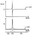
図1bは、隣接補強体の非存在下で、コイル200の供給周波数が変化したときの、Ls(曲線300)及びRs(曲線400)のそれぞれの値の変動を示す。このようにコイル200の3つの動作領域が現れることが示される。
FIG. 1b shows the variation of the respective values of Ls (curve 300) and Rs (curve 400) when the supply frequency of the
第1の領域500は、抵抗と直列に配置されたインダクタンスによるコイル200のモデル化が有効な動作モードに対応する。
The
第2の領域600は、抵抗の値Rsがこのコイル200にもはや供給することができない点まで増大しているので、インダクタンス200が反共振回路として作用する領域に対応する。この領域を定める周波数Fcの位置決めは、コイル200の特性に直接依存し、これは例えば、その巻きの数、そのオーム抵抗、巻線を形成するために用いられる導電ワイヤの直径、又は巻線を形成する材料の性質を含むがこれらに限定されない。
The
第3の領域700は、コイル200がもはや純粋な抵抗と直列に配置された純粋なインダクタンスに単純に相似していない動作領域である。この場合、キャパシタンスCsをモデルに追加しなければならない。モデル化スキームによれば、このキャパシタンスCsは、純粋なインダクタンスLsと並列に配置され、又はインダクタンスLsと抵抗Rsとの組合せによって形成された対と並列に配置される。
The
領域500は、本発明によるゴム様材料の層の厚さを測定するための方法の適用に好ましい領域である。
図2aは、自由面の反対側の面上に隣接補強体30を有する材料10の層の厚さを測定するための、本発明による方法の実行を示す。この補強体30は、非常に高抵抗性のゴム様材料のマトリックスによって互いに平行に組み立てられた鋼コードから形成されている。このようにして形成された補強体は、コードが互いに接触せずに、抵抗性マトリックスで機械的に接続されているので、非常に低い電気伝導率を有する。しかしながら、この補強体は、ケーブルが強磁性なので、良好な磁場の導体である。
FIG. 2a shows the performance of the method according to the invention for measuring the thickness of a layer of
本発明による方法の第1のステップは、平らなコイル20を材料10の層の自由面に当接して配置することである。次いで、このコイルに、その周波数がコイルのカットオフ周波数Fcを下回る供給信号が供給される。次いで、コイルの端子において観測される抵抗の変動が測定される。
The first step of the method according to the invention is to place a
上述のように、コイル20は、純粋なインダクタンスLsと、抵抗Rsとの組合せと等価である。コイル20と補強体30との間の所与の距離に対して、コイル20の供給信号の周波数を変化させたとき、Rsの値の変動が観測される。
As described above, the
この変動は、一方で、図1bに示すように、Fcを下回る周波数において補強体の非存在下で見いだされる変動と、他方で、コイル20の近くの補強材30の存在に起因する変動との組合せである。 This variation is, on the one hand, the variation found in the absence of a reinforcement at a frequency below Fc, as shown in FIG. It is a combination.
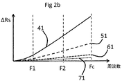
図2bは、量ΔRsの変動を示し、これはコイル20の近くの補強体30の存在にのみ起因するRsの変動の部分に対応する。図2bにおいて、この変動は、コイル20の供給信号の周波数の関数として示される。
FIG. 2 b shows the variation of the quantity ΔRs, which corresponds to the portion of the variation of Rs that is only due to the presence of the reinforcement 30 near the
したがって、曲線41は、ゴム様材料10の厚さが1ミリメートルのときに見いだされるΔRsの変動を示す。
Thus,
曲線51は、ゴム様材料10の厚さが5ミリメートルのときに見いだされるΔRsの変動を示す。
曲線61は、ゴム様材料10の厚さが10ミリメートルのときに見いだされるΔRsの変動を示す。
最後に、曲線71は、ゴム様材料10の厚さが20ミリメートルのときに見いだされるΔRsの変動を示す。
Finally,
全ての場合において、用いられる供給信号の周波数は、図1a及び図1bの例で定められた周波数Fcを下回ったままである。 In all cases, the frequency of the supply signal used remains below the frequency Fc defined in the examples of FIGS. 1a and 1b.
供給周波数が周波数Fcよりかなり下のレベルF1に設定された場合、1ミリメートルと20ミリメートルとの間で変化する層の厚さの変動に対して、この周波数F1で得られるΔRsの変動を分離することは困難であることが見いだされた。 If the feed frequency is set to a level F1 well below the frequency Fc, it separates the variation in ΔRs obtained at this frequency F1 from the variation in layer thickness that varies between 1 and 20 millimeters. It was found to be difficult.
しかしながら、供給信号の周波数がより高いレベルF2に設定された場合、ゴム様材料の層の厚さが1ミリメートルと20ミリメートルとの間で変化したときに、ΔRsの変動は、より良い感度をもたらすことができること見いだされるであろう。 However, when the frequency of the feed signal is set to a higher level F2, the variation in ΔRs results in better sensitivity when the thickness of the layer of rubber-like material varies between 1 and 20 millimeters. You will find that you can.
この場合、ΔRsの変動をゴム様材料の厚さの測定のために用いることが可能になる。 In this case, the variation of ΔRs can be used for measuring the thickness of the rubber-like material.
本発明による方法の変形において、コイル20の供給周波数が高い値の場合、層の厚さを測定するために、ΔLs及びΔRsの変動を同時に用いることもまた可能である。
In a variant of the method according to the invention, it is also possible to simultaneously use variations in ΔLs and ΔRs to measure the layer thickness when the supply frequency of the
なぜなら、この場合、渦電流の非存在下で、ΔLsは、コイル20と補強体30との間の距離が減少するにつれて増大するからである。したがって、この変動は、ΔRsがコイル20と補強体30との間の距離が減少するにつれて増大することから、ΔRsの変動と同じ方向に従う。
This is because, in this case, in the absence of eddy current, ΔLs increases as the distance between the
ΔRsの変動は、それ自体で、又はΔLsの変動と組み合わせて用いることができることが有利である。この実施形態は、排他的ではないが、特にコイル20の供給周波数が上記で定められた周波数Fcの10パーセントを上回る場合に用いられる。
Advantageously, variations in ΔRs can be used by themselves or in combination with variations in ΔLs. This embodiment is not exclusive, but is used in particular when the supply frequency of the
別の選択肢として、Ls及びRsの変動を、直接的に、別個に、又は組み合わせて用いて、ゴム様材料の層の厚さの測定を提供することができる。このようにして測定された距離は、ゴム様材料層の自由面と層内に存在する金属補強体との間の距離に対応する。したがって、感度要素をトレッドパターンの上部に向かって近づけることにより、トレッドパターンの上部と金属補強体との間の初期距離と、測定された距離とを比較することによって、タイヤの摩耗を判定することができる。 As another option, variations in Ls and Rs can be used directly, separately or in combination to provide a measure of the layer thickness of the rubber-like material. The distance thus measured corresponds to the distance between the free surface of the rubber-like material layer and the metal reinforcement present in the layer. Therefore, tire wear is determined by comparing the measured distance with the initial distance between the upper part of the tread pattern and the metal reinforcement by bringing the sensitivity element closer to the upper part of the tread pattern. Can do.
10:材料
20:コイル
30:補強体
41:材料の厚さが1ミリメートルのときのΔRsの変動
51:材料の厚さが5ミリメートルのときのΔRsの変動
61:材料の厚さが10ミリメートルのときのΔRsの変動
71:材料の厚さが20ミリメートルのときのΔRsの変動
100:電子的測定回路
200:コイル
210:ヒステリシス・サイクル
500:第1の領域
600:第2の領域
700:第3の領域
10: Material 20: Coil 30: Reinforcement body 41: Change in ΔRs when material thickness is 1 millimeter 51: Change in ΔRs when material thickness is 5 millimeters 61: Material thickness is 10 millimeters ΔRs variation 71: ΔRs
Claims (10)
−交番磁場を発生する感度要素を、その厚さが測定される前記材料層に向かって近づけるステップと、
−前記隣接補強体におけるヒステリシス損を測定するステップであって、これらの損失は前記感度要素の端子において測定される、ステップと、
−これらのヒステリシス損に基づいて前記材料層の厚さを評価するステップと、
を含むことを特徴とする、方法。 A method for measuring the thickness of a layer of rubber-like material, which is joined to a free surface in contact with air and adjacent reinforcements made of elements that are electrically isolated from each other Each of these elements comprises at least one hysteresis material having a permeability greater than that of air, said method comprising:
-Bringing the sensitivity element generating an alternating magnetic field closer to the material layer whose thickness is to be measured;
Measuring hysteresis losses in the adjacent reinforcements, these losses being measured at the terminals of the sensitivity element;
-Evaluating the thickness of the material layer based on these hysteresis losses;
A method comprising the steps of:
−この供給信号の周波数を変化させるステップと、
を含むことを特徴とする、請求項1に記載の方法。 -Supplying an alternating electrical signal to the sensitivity element;
-Changing the frequency of this supply signal;
The method of claim 1, comprising:
前記方法は、前記感度要素を前記材料層に向かって近づける前記ステップが、前記感度要素を、コイルを形成する前記巻線に平行な平面が前記自由面の表面に対して平行になるように位置決めすることにあることを特徴とする、請求項1〜7のいずれかに記載の方法。 The sensitivity element is formed from a winding;
In the method, the step of bringing the sensitivity element closer to the material layer positions the sensitivity element such that a plane parallel to the winding forming a coil is parallel to the surface of the free surface. 8. A method according to any of claims 1 to 7, characterized in that:
Applications Claiming Priority (3)
| Application Number | Priority Date | Filing Date | Title |
|---|---|---|---|
| FR1462589 | 2014-12-17 | ||
| FR1462589A FR3030717B1 (en) | 2014-12-17 | 2014-12-17 | METHOD FOR MEASURING THE THICKNESS OF A LAYER OF RUBBER MATERIAL |
| PCT/EP2015/079454 WO2016096661A1 (en) | 2014-12-17 | 2015-12-11 | Method for measuring the thickness of a layer of rubber-like material |
Publications (1)
| Publication Number | Publication Date |
|---|---|
| JP2018507394A true JP2018507394A (en) | 2018-03-15 |
Family
ID=52589616
Family Applications (1)
| Application Number | Title | Priority Date | Filing Date |
|---|---|---|---|
| JP2017533273A Pending JP2018507394A (en) | 2014-12-17 | 2015-12-11 | Method for measuring the thickness of a layer of rubber-like material |
Country Status (6)
| Country | Link |
|---|---|
| US (1) | US10190863B2 (en) |
| EP (1) | EP3234540B8 (en) |
| JP (1) | JP2018507394A (en) |
| CN (1) | CN107407547B (en) |
| FR (1) | FR3030717B1 (en) |
| WO (1) | WO2016096661A1 (en) |
Families Citing this family (6)
| Publication number | Priority date | Publication date | Assignee | Title |
|---|---|---|---|---|
| FR3020680B1 (en) | 2014-05-02 | 2017-11-24 | Michelin & Cie | SYSTEM FOR EVALUATING THE CONDITION OF A TIRE |
| FR3030374B1 (en) | 2014-12-17 | 2017-01-13 | Michelin & Cie | METHOD FOR DETECTING AND WARNING OF THE UNDER-INFLATION CONDITION OF A TIRE |
| FR3030744A1 (en) | 2014-12-17 | 2016-06-24 | Michelin & Cie | SYSTEM FOR EVALUATING THE CONDITION OF A TIRE |
| FR3039459B1 (en) | 2015-07-30 | 2017-08-11 | Michelin & Cie | SYSTEM FOR EVALUATING THE CONDITION OF A TIRE |
| CN111497528A (en) * | 2019-01-04 | 2020-08-07 | 益力半导体股份有限公司 | Variable-capacity tire thickness sensor |
| CN114383493B (en) * | 2022-02-28 | 2024-01-30 | 中国工程物理研究院总体工程研究所 | Non-contact metal surface non-conductive coating thickness measuring method |
Family Cites Families (18)
| Publication number | Priority date | Publication date | Assignee | Title |
|---|---|---|---|---|
| US3675375A (en) * | 1971-03-11 | 1972-07-11 | Goodyear Tire & Rubber | Method for measuring the thickness of buffed tires |
| US4150567A (en) * | 1978-06-29 | 1979-04-24 | Allied Chemical Corporation | Method of estimating energy loss from pneumatic tires |
| US4297878A (en) * | 1980-03-07 | 1981-11-03 | Allied Corporation | Measuring coefficient of radial damping of tire wall segment |
| DE3361224D1 (en) * | 1982-07-09 | 1985-12-19 | Fraunhofer Ges Forschung | Device for non destructive measuring of the case hardening depth of a material |
| DE3507651C1 (en) * | 1985-03-05 | 1986-04-10 | RSM Regel-, Steuer- und Messtechnik GmbH, 4000 Düsseldorf | Thickness measuring device for elongated, extruded plastic objects |
| DE9013605U1 (en) * | 1990-09-28 | 1991-01-24 | Elektro-Physik Hans Nix & Dr.-Ing. E. Steingroever Gmbh & Co Kg, 5000 Koeln, De | |
| GB2356050B (en) * | 1999-11-05 | 2001-10-24 | Elcometer Instr Ltd | Apparatus and method for measuring thickness |
| WO2008059283A1 (en) | 2006-11-17 | 2008-05-22 | Treadcheck Limited | Apparatus and method for monitoring tyre wear |
| FR2910842B1 (en) * | 2006-12-28 | 2011-03-11 | Michelin Soc Tech | PNEUMATIC IMPROVED ENDURANCE AGAINST EXTERNAL SHOCKS |
| US7578180B2 (en) * | 2007-06-29 | 2009-08-25 | The Goodyear Tire & Rubber Company | Tread depth sensing device and method for measuring same |
| US9063190B2 (en) * | 2011-09-02 | 2015-06-23 | Ivan GARSHELIS | Magnetostatic measurement method and sensor for assessing local hysteresis properties in ferromagnetic materials |
| DE102012017784B4 (en) * | 2012-09-07 | 2018-08-23 | Fraunhofer-Gesellschaft zur Förderung der angewandten Forschung e.V. | Method, device and use of the device for nondestructive quantitative determination of layer thicknesses of a layered body |
| US9182212B2 (en) * | 2012-11-07 | 2015-11-10 | Olympus Ndt, Inc. | Hall effect probe with exchangeable wear tips |
| CN103234449B (en) * | 2013-05-09 | 2015-12-09 | 清华大学 | Reduce electrically conductive film method for measuring thickness and the device of lift-off influence of fluctuations |
| FR3007517B1 (en) | 2013-06-20 | 2016-08-19 | Michelin & Cie | SYSTEM FOR MEASURING THE THICKNESS OF A GUM LAYER OF A TIRE |
| FR3009075B1 (en) | 2013-07-26 | 2016-09-09 | Michelin & Cie | SYSTEM FOR MEASURING THE THICKNESS OF A GUM LAYER OF A TIRE |
| FR3009076B1 (en) | 2013-07-26 | 2017-03-31 | Michelin & Cie | SYSTEM FOR MEASURING THE THICKNESS OF A GUM LAYER OF A TIRE |
| FR3020680B1 (en) | 2014-05-02 | 2017-11-24 | Michelin & Cie | SYSTEM FOR EVALUATING THE CONDITION OF A TIRE |
-
2014
- 2014-12-17 FR FR1462589A patent/FR3030717B1/en not_active Expired - Fee Related
-
2015
- 2015-12-11 US US15/535,138 patent/US10190863B2/en active Active
- 2015-12-11 EP EP15808594.4A patent/EP3234540B8/en active Active
- 2015-12-11 JP JP2017533273A patent/JP2018507394A/en active Pending
- 2015-12-11 CN CN201580069122.9A patent/CN107407547B/en active Active
- 2015-12-11 WO PCT/EP2015/079454 patent/WO2016096661A1/en active Application Filing
Also Published As
| Publication number | Publication date |
|---|---|
| EP3234540B8 (en) | 2018-11-21 |
| CN107407547B (en) | 2020-07-07 |
| EP3234540B1 (en) | 2018-09-26 |
| CN107407547A (en) | 2017-11-28 |
| EP3234540A1 (en) | 2017-10-25 |
| US20170322012A1 (en) | 2017-11-09 |
| FR3030717B1 (en) | 2017-01-13 |
| FR3030717A1 (en) | 2016-06-24 |
| US10190863B2 (en) | 2019-01-29 |
| WO2016096661A1 (en) | 2016-06-23 |
Similar Documents
| Publication | Publication Date | Title |
|---|---|---|
| JP2018507394A (en) | Method for measuring the thickness of a layer of rubber-like material | |
| US10876826B2 (en) | System for determining the thickness of a rubber layer of a tire | |
| US10113855B2 (en) | System for determining the thickness of a layer of rubber for a tire | |
| AU2014294973B2 (en) | System for measuring the thickness of a liner layer of a tyre | |
| WO2015083072A1 (en) | Sensor device adapted for vehicle tyres, vehicle tyres and method of monitoring depths of grooves of tyre treads | |
| CN107000503B (en) | Determine the System and method for of at least one tyre contact area parameter of the size of the tyre contact area on the tire of characterization wheel | |
| JP6677347B2 (en) | Pneumatic tire, tire wear information acquisition system, and pneumatic tire wear information acquisition method | |
| US20070295074A1 (en) | Method for estimating a tire running condition and an apparatus for effecting the method and a tire with sensors disposed therein | |
| JP4869917B2 (en) | Wear level indicating tire | |
| DE19745734A1 (en) | Wear sensor measuring tread depth of tires continuously | |
| JPWO2005016670A1 (en) | Sensor built-in tire and tire condition estimation method | |
| CN107438757A (en) | For the method for the under-inflation state for detecting and sending signal prompt tire | |
| US11774301B2 (en) | Tire load estimation system and method | |
| JP7068504B2 (en) | Tire wear measuring device | |
| JP6365601B2 (en) | Magnetic marker detection system and magnetic marker detection method | |
| KR20020065852A (en) | Measurements of adherence between a vehicle wheel and the roadway | |
| JP4296917B2 (en) | Tire state estimating device and tire | |
| CN108548676B (en) | Vehicle obstacle crossing capability test method | |
| CN109311481A (en) | Method for determining road condition | |
| JP2016529479A (en) | System for measuring the thickness of rubber layers for tires | |
| WO2021206023A1 (en) | Device and method for measuring tire wear | |
| JP7387023B2 (en) | Tire wear measurement device, pneumatic tires and tire wear measurement method | |
| US20240060925A1 (en) | Apparatuses and methods for detecting cracks | |
| US20160161344A1 (en) | Temperature Measurement Using a Magnetic Ranging Tool | |
| JP2008143312A (en) | Estimation method of road surface state, estimation device of road surface state, tire and vehicle control device |