JP2018506367A - Metered dose inhaler - Google Patents
Metered dose inhaler Download PDFInfo
- Publication number
- JP2018506367A JP2018506367A JP2017544720A JP2017544720A JP2018506367A JP 2018506367 A JP2018506367 A JP 2018506367A JP 2017544720 A JP2017544720 A JP 2017544720A JP 2017544720 A JP2017544720 A JP 2017544720A JP 2018506367 A JP2018506367 A JP 2018506367A
- Authority
- JP
- Japan
- Prior art keywords
- valve
- metering
- inlet
- dose
- valve stem
- Prior art date
- Legal status (The legal status is an assumption and is not a legal conclusion. Google has not performed a legal analysis and makes no representation as to the accuracy of the status listed.)
- Pending
Links
Images


Classifications
-
- B—PERFORMING OPERATIONS; TRANSPORTING
- B65—CONVEYING; PACKING; STORING; HANDLING THIN OR FILAMENTARY MATERIAL
- B65D—CONTAINERS FOR STORAGE OR TRANSPORT OF ARTICLES OR MATERIALS, e.g. BAGS, BARRELS, BOTTLES, BOXES, CANS, CARTONS, CRATES, DRUMS, JARS, TANKS, HOPPERS, FORWARDING CONTAINERS; ACCESSORIES, CLOSURES, OR FITTINGS THEREFOR; PACKAGING ELEMENTS; PACKAGES
- B65D83/00—Containers or packages with special means for dispensing contents
- B65D83/14—Containers or packages with special means for dispensing contents for delivery of liquid or semi-liquid contents by internal gaseous pressure, i.e. aerosol containers comprising propellant for a product delivered by a propellant
- B65D83/44—Valves specially adapted therefor; Regulating devices
- B65D83/52—Valves specially adapted therefor; Regulating devices for metering
- B65D83/54—Metering valves ; Metering valve assemblies
- B65D83/546—Metering valves ; Metering valve assemblies the metering occurring at least partially in the actuating means
-
- A—HUMAN NECESSITIES
- A61—MEDICAL OR VETERINARY SCIENCE; HYGIENE
- A61M—DEVICES FOR INTRODUCING MEDIA INTO, OR ONTO, THE BODY; DEVICES FOR TRANSDUCING BODY MEDIA OR FOR TAKING MEDIA FROM THE BODY; DEVICES FOR PRODUCING OR ENDING SLEEP OR STUPOR
- A61M15/00—Inhalators
- A61M15/009—Inhalators using medicine packages with incorporated spraying means, e.g. aerosol cans
-
- B—PERFORMING OPERATIONS; TRANSPORTING
- B65—CONVEYING; PACKING; STORING; HANDLING THIN OR FILAMENTARY MATERIAL
- B65D—CONTAINERS FOR STORAGE OR TRANSPORT OF ARTICLES OR MATERIALS, e.g. BAGS, BARRELS, BOTTLES, BOXES, CANS, CARTONS, CRATES, DRUMS, JARS, TANKS, HOPPERS, FORWARDING CONTAINERS; ACCESSORIES, CLOSURES, OR FITTINGS THEREFOR; PACKAGING ELEMENTS; PACKAGES
- B65D83/00—Containers or packages with special means for dispensing contents
- B65D83/14—Containers or packages with special means for dispensing contents for delivery of liquid or semi-liquid contents by internal gaseous pressure, i.e. aerosol containers comprising propellant for a product delivered by a propellant
- B65D83/44—Valves specially adapted therefor; Regulating devices
- B65D83/52—Valves specially adapted therefor; Regulating devices for metering
- B65D83/54—Metering valves ; Metering valve assemblies
-
- G—PHYSICS
- G01—MEASURING; TESTING
- G01F—MEASURING VOLUME, VOLUME FLOW, MASS FLOW OR LIQUID LEVEL; METERING BY VOLUME
- G01F11/00—Apparatus requiring external operation adapted at each repeated and identical operation to measure and separate a predetermined volume of fluid or fluent solid material from a supply or container, without regard to weight, and to deliver it
- G01F11/10—Apparatus requiring external operation adapted at each repeated and identical operation to measure and separate a predetermined volume of fluid or fluent solid material from a supply or container, without regard to weight, and to deliver it with measuring chambers moved during operation
- G01F11/12—Apparatus requiring external operation adapted at each repeated and identical operation to measure and separate a predetermined volume of fluid or fluent solid material from a supply or container, without regard to weight, and to deliver it with measuring chambers moved during operation of the valve type, i.e. the separating being effected by fluid-tight or powder-tight movements
- G01F11/14—Apparatus requiring external operation adapted at each repeated and identical operation to measure and separate a predetermined volume of fluid or fluent solid material from a supply or container, without regard to weight, and to deliver it with measuring chambers moved during operation of the valve type, i.e. the separating being effected by fluid-tight or powder-tight movements wherein the measuring chamber reciprocates
-
- F—MECHANICAL ENGINEERING; LIGHTING; HEATING; WEAPONS; BLASTING
- F16—ENGINEERING ELEMENTS AND UNITS; GENERAL MEASURES FOR PRODUCING AND MAINTAINING EFFECTIVE FUNCTIONING OF MACHINES OR INSTALLATIONS; THERMAL INSULATION IN GENERAL
- F16K—VALVES; TAPS; COCKS; ACTUATING-FLOATS; DEVICES FOR VENTING OR AERATING
- F16K31/00—Actuating devices; Operating means; Releasing devices
- F16K31/12—Actuating devices; Operating means; Releasing devices actuated by fluid
- F16K31/126—Actuating devices; Operating means; Releasing devices actuated by fluid the fluid acting on a diaphragm, bellows, or the like
- F16K31/1268—Actuating devices; Operating means; Releasing devices actuated by fluid the fluid acting on a diaphragm, bellows, or the like with a plurality of the diaphragms
-
- F—MECHANICAL ENGINEERING; LIGHTING; HEATING; WEAPONS; BLASTING
- F16—ENGINEERING ELEMENTS AND UNITS; GENERAL MEASURES FOR PRODUCING AND MAINTAINING EFFECTIVE FUNCTIONING OF MACHINES OR INSTALLATIONS; THERMAL INSULATION IN GENERAL
- F16K—VALVES; TAPS; COCKS; ACTUATING-FLOATS; DEVICES FOR VENTING OR AERATING
- F16K7/00—Diaphragm valves or cut-off apparatus, e.g. with a member deformed, but not moved bodily, to close the passage ; Pinch valves
- F16K7/12—Diaphragm valves or cut-off apparatus, e.g. with a member deformed, but not moved bodily, to close the passage ; Pinch valves with flat, dished, or bowl-shaped diaphragm
Abstract
定量吸入器の、又はこれに関連する改善本発明は、ターボフォレシスの問題に対処し、定量吸入器、特に加圧噴霧式定量吸入器のために比較的単純で安価な解決法を提示する。計量バルブ(100)は、バルブ本体(110)と、バルブ本体(110)内に取り付けられたバルブステム(130)と、バルブステム(130)を「停止」位置に付勢するためのばね要素(140)とを備える。計量前領域(170)は、入口(180)に小型バルブシール(210)を備える、バルブステム(130)内に形成される。小型バルブシール(210)は、バルブステム(130)が「停止」位置にあるときに、計量バルブ(100)が取り付けられたキャニスター(1)内の、周囲のバルク配合物(4)から、計量前領域(170)を効果的に分離する。Improvements to or in connection with metered dose inhalers The present invention addresses the problem of turbophoresis and presents a relatively simple and inexpensive solution for metered dose inhalers, particularly pressurized atomized metered dose inhalers. The metering valve (100) includes a valve body (110), a valve stem (130) mounted within the valve body (110), and a spring element (for biasing the valve stem (130) to a “stop” position ( 140). A pre-metering region (170) is formed in the valve stem (130) with a small valve seal (210) at the inlet (180). The small valve seal (210) is metered from the surrounding bulk formulation (4) in the canister (1) to which the metering valve (100) is attached when the valve stem (130) is in the “stop” position. Effectively isolate the front region (170).
Description
本発明は、定量吸入器の改善又はこれに関連する改善に関し、より具体的には、加圧噴霧式定量吸入装置に関わる。 The present invention relates to improvements in or related to metered dose inhalers, and more particularly to pressurized spray metered dose inhalers.
加圧噴霧式定量吸入装置(pMDI装置)は、作動時にユーザ又は患者に所定の用量の薬剤を分配するように設計されている。薬剤は、懸濁液中に活性粒子を有する又は流体中に溶解された活性物質を含む流体として、貯蔵及び分配される。装置が起動されると、計量領域から、当該用量の薬剤を分配するために、装置内のバルブの動作が使用される。しかしながら、懸濁液内の粒子が流体乱流の減少する方向(計量チャンバに入る場合も、出る場合もありうる)に移動する際に、用量のばらつき、すなわち、用量の増加又は用量の減少が生じる場合があり、よって、患者に供給される薬剤の実際の用量のばらつきが生じる。この移動は、ターボフォレシスとして知られる現象である。 Pressurized metered dose inhalers (pMDI devices) are designed to dispense a predetermined dose of medication to a user or patient when activated. The drug is stored and dispensed as a fluid containing active substances having active particles in suspension or dissolved in fluid. When the device is activated, the action of a valve in the device is used to dispense that dose of drug from the metering area. However, as the particles in the suspension move in the direction of decreasing fluid turbulence (which may enter or exit the metering chamber), dose variations, i.e. dose increases or dose decreases, May occur, thus resulting in variations in the actual dose of drug delivered to the patient. This movement is a phenomenon known as turbophoresis.
国際公開第02/10037(A)号は、計量チャンバの内部又は外部への用量増加又は用量減少の影響を直接的に防止するために、pMDI装置が停止しているときに、バルブ定量チャンバを閉止する方法を記載している。しかしながら、バルブの臨界計量前領域(critical pre−metering region)において生じる用量増加又は用量減少の影響は対処されていないため、停止時に計量チャンバが閉止しているときでも、計量前領域に入る、又はここから出る粒子のために、用量増加又は用量減少は依然として生じ得る。これは患者が、患者自身の過失がなくとも、常に適切な薬剤の投与を受けられるとは限らない場合があることを意味している。 WO 02/10037 (A) describes a valve metering chamber when the pMDI device is stopped to directly prevent the effects of dose increase or dose decrease inside or outside the metering chamber. Describes how to close. However, the effects of dose increase or dose decrease that occur in the critical pre-metering region of the valve are not addressed, so even when the metering chamber is closed at the time of shutdown, Due to the particles exiting here, a dose increase or dose decrease may still occur. This means that a patient may not always receive the appropriate medication without the patient's own negligence.
本発明の目的は、ターボフォレシスの影響が少なくとも実質的に低減された、改善された加圧噴霧式定量吸入器を提示することである。 It is an object of the present invention to provide an improved pressurized spray metered dose inhaler in which the effects of turbophoresis are at least substantially reduced.
別の目的は、ターボフォレシスの影響を低費用で実質的に低減する、単純かつ効果的な方法を提示することである。 Another object is to present a simple and effective way to substantially reduce the impact of turbophoresis at low cost.
本発明の一態様により、
ハウジングと、
ハウジング内に取り付けられ、入口を有するバルブ本体と、
バルブ本体内で、少なくとも第1位置と第2位置との間で、バルブ本体に対して可動である、バルブステムと、
バルブ本体内に配置され、バルブステムを第1位置へと付勢するように動作可能である、戻り部材と、
バルブステムの第1部分内に形成され、入口ポート及び出口ポートを含む計量前領域であって、入口ポートはバルブ本体の入口に接続されている、計量前領域と、
バルブステムとバルブハウジングとの間に形成された計量チャンバであって、計量前領域の出口ポートに接続可能な、計量チャンバと、
計量前領域への入口経路内に位置付けられ、計量した用量を計量前領域内に保持するように動作可能な、第1用量保持要素であって、第1用量保持要素を通じて双方向への流体の移送をもたらす、第1用量保持要素と、
バルブステムの第2部分内に形成され、分配入口及び分配出口を有する、分配チャネルであって、分配入口は第2位置において計量チャンバに接続可能である、分配チャネルと、を含む、計量バルブが提示される。
According to one aspect of the invention,
A housing;
A valve body mounted in the housing and having an inlet;
A valve stem movable within the valve body relative to the valve body at least between a first position and a second position;
A return member disposed within the valve body and operable to bias the valve stem to the first position;
A pre-metering region formed in the first portion of the valve stem and including an inlet port and an outlet port, the inlet port connected to the inlet of the valve body;
A metering chamber formed between the valve stem and the valve housing, the metering chamber connectable to an outlet port in the pre-metering region;
A first dose-holding element positioned in the inlet path to the pre-metering region and operable to hold a metered dose in the pre-metering region, wherein the fluid flows in both directions through the first dose-holding element. A first dose-carrying element that provides transfer;
A dispensing channel formed in the second portion of the valve stem and having a dispensing inlet and a dispensing outlet, the dispensing inlet being connectable to the metering chamber in a second position; Presented.
計量前領域への入口経路内に、第1用量保持要素を設けることによって、ターボフォレシスの現象が少なくとも実質的に低減することがあり、結果的に、計量前領域内に入る、及びここから出る活性粒子の移動によって、用量が減少又は増加しない、計量された用量を分配する能力が得られる。 By providing a first dose-holding element in the entrance path to the pre-weighing region, the phenomenon of turbophoresis may be at least substantially reduced, resulting in entering and leaving the pre-weighing region. The movement of the active particles provides the ability to dispense a metered dose without reducing or increasing the dose.
第1用量保持要素は、バルブを起動して薬剤を患者に分配する前に、計量前領域及び計量チャンバ内に薬剤の活性粒子を捕捉するバルブシールとして機能する。加えて、第1用量保持要素は、加圧噴霧式定量吸入器内の計量バルブの周囲のバルク配合物から、計量前領域を効果的に分離する。 The first dose retention element functions as a valve seal that traps the active particles of the drug in the pre-metering area and the metering chamber before activating the valve and dispensing the drug to the patient. In addition, the first dose retaining element effectively separates the pre-metering region from the bulk formulation around the metering valve in the pressurized spray metered dose inhaler.
一実施形態において、第1用量保持部材は、計量前領域への入口に位置し、入口は入口ポートに実質的に隣接する。 In one embodiment, the first dose retaining member is located at the entrance to the pre-metering region, the entrance being substantially adjacent to the entrance port.
第1用量保持部材を、計量前領域への入口に配置することにより、第1用量保持部材を、バルブステム内の計量前領域への入口に容易に固定することができ、計量バルブの組み立ては比較的単純になる。 By placing the first dose retaining member at the inlet to the pre-metering region, the first dose retaining member can be easily secured to the inlet to the pre-metering region in the valve stem, It becomes relatively simple.
出口ポートは好ましくは、バルブステムの外周壁面の開口部を含む。 The outlet port preferably includes an opening in the outer peripheral wall surface of the valve stem.
一実施形態において、入口ポートは、バルブステムの近位端にある開口部を含む。この実施形態において、第1用量保持部材は、入口ポートと実質的に位置合わせされた軸を有し得る。他の実施形態において、第1用量保持部材は、出口ポートと実質的に位置合わせされた軸を有し得る。本来、第1用量保持部材の位置合わせは、計量バルブの特定の構成に依存する。 In one embodiment, the inlet port includes an opening at the proximal end of the valve stem. In this embodiment, the first dose retaining member may have an axis that is substantially aligned with the inlet port. In other embodiments, the first dose retaining member can have an axis substantially aligned with the outlet port. Naturally, the alignment of the first dose retaining member depends on the particular configuration of the metering valve.
一実施形態において、入口ポートは、出口ポートから離れて配置されたバルブステムの外周壁面の開口部を含む。一実施形態において、第1用量保持部材は、入口ポートと実質的に位置合わせされた軸を有し得る。他の実施形態において、第1用量保持部材は、出口ポートと実質的に位置合わせされた軸を有し得る。第1用量保持部材の位置合わせは、計量バルブの構成に従う。 In one embodiment, the inlet port includes an opening in the outer peripheral wall surface of the valve stem that is located away from the outlet port. In one embodiment, the first dose retaining member can have an axis substantially aligned with the inlet port. In other embodiments, the first dose retaining member can have an axis substantially aligned with the outlet port. The alignment of the first dose retaining member follows the configuration of the metering valve.
第1用量保持部材は、エラストマーディスクを備えてよく、エラストマーディスクの中央領域には少なくとも1つの再シール可能なスリットが設けられている。 The first dose retaining member may comprise an elastomeric disk, and at least one resealable slit is provided in the central region of the elastomeric disk.
第1用量保持部材としてエラストマーディスクを有することにより、これを、計量前領域への入口経路、又は計量前領域への入口のいずれかにおいて、バルブステム内の適切な位置へと撓ませて挿入できる。 By having an elastomeric disc as the first dose-holding member, it can be flexed and inserted into the appropriate position in the valve stem either in the inlet path to the pre-metering region or the inlet to the pre-metering region. .
一実施形態において、エラストマーディスクは、その中央領域よりも厚い周辺領域を有する。これは、エラストマーディスクの取り扱いを容易にするという、利益を有する。理想的には、エラストマーディスクは対称である、すなわち、上下がない。これにより、計量前領域の入口経路、又は計量前領域への入口において、バルブステム内へと、より単純なアセンブリ装置によって容易に挿入可能となる。エラストマーディスクは、エラストマー、又は熱可塑性エラストマーから成形することができる。好ましくは、成形された物品を細い刃で切断することによって、再シール可能なスリットがもたらされる。 In one embodiment, the elastomeric disk has a peripheral region that is thicker than its central region. This has the benefit of facilitating handling of the elastomeric disk. Ideally, the elastomeric disk is symmetrical, i.e., not top and bottom. This allows easy insertion into the valve stem at the inlet path of the pre-metering region or the inlet to the pre-metering region with a simpler assembly device. The elastomer disk can be molded from an elastomer or a thermoplastic elastomer. Preferably, the molded article is cut with a fine blade to provide a resealable slit.
別の実施形態において、第2用量保持部材が、計量前領域の出口経路に位置付けられる。一実施形態において、第2用量保持部材が、計量前領域の出口に配置される。各場合において、第2用量保持部材は、出口ポートと実質的に位置合わせされた軸を有し得る。 In another embodiment, the second dose retaining member is positioned in the exit path of the pre-metering region. In one embodiment, a second dose retaining member is located at the exit of the pre-metering area. In each case, the second dose retaining member may have an axis that is substantially aligned with the outlet port.
計量前領域からの出口経路、又は計量前領域の出口に第2用量保持部材を設けることにより、計量前領域は、バルク配合物及び計量チャンバの両方から効果的に分離することができる。この分離はまた、ターボフォレシスの影響を低減するのにも役立つ。 By providing a second dose retention member at the exit path from the pre-metering region or at the outlet of the pre-metering region, the pre-metering region can be effectively separated from both the bulk formulation and the metering chamber. This separation also helps to reduce the effects of turbophoresis.
第2用量保持部材はエラストマーディスクを備えてよく、エラストマーディスクの中央領域には少なくとも1つの再シール可能なスリットが設けられている。一実施形態において、エラストマーディスクは、その中央領域よりも厚い周辺領域を有する。好ましくは第2用量保持部材は、第1用量保持部材と実質的に同一である。 The second dose retention member may comprise an elastomeric disk, and at least one resealable slit is provided in the central region of the elastomeric disk. In one embodiment, the elastomeric disk has a peripheral region that is thicker than its central region. Preferably, the second dose holding member is substantially the same as the first dose holding member.
同一の用量保持部材を有することにより、これらは互換可能となり、結果的に計量バルブの組み立てを容易にする。加えて、用量保持部材は、これらが上下対称であるため、その向きにかかわらず、計量バルブ内で容易に組み立てることができる。 By having the same dose-retaining member, they are interchangeable and consequently facilitate assembly of the metering valve. In addition, the dose-holding members can be easily assembled in the metering valve regardless of their orientation because they are vertically symmetrical.
本発明をよりよく理解するために、ここで、例として、以下の添付の図面を参照する。
本発明は、特定の実施形態に関して、かついくつかの図面を参照して説明されるが、本発明はこれらに限定されるものではない。上記の図面は、概略的であり、限定するものではない。図面中、例示の目的のため、要素のいくつかの大きさは誇張されており、縮尺どおりに描かれていないことがある。 The present invention will be described with respect to particular embodiments and with reference to certain drawings but the invention is not limited thereto. The above drawings are schematic and are not limiting. In the drawings, the size of some of the elements may be exaggerated and not drawn on scale for illustrative purposes.
本発明により、小型のバルブシールを、pMDI装置の計量前領域への入口に配置することにより、ターボフォレシスの影響が実質的に減少するか、いくつかの場合においては防がれることが見出された。 In accordance with the present invention, it has been found that placing a small valve seal at the entrance to the pre-metering region of the pMDI device substantially reduces or prevents in some cases the effects of turbophoresis. It was done.
ターボフォレシスの潜在的な影響、及びこのような影響を防ぐ方法をより良く理解するために、pMDI装置の動作についての議論が示される。pMDI装置のバルブは、計量領域及び計量前領域を有し、計量前領域は低乱流領域であり、高乱流領域であるバルク配合物と直接流体接触している。あらゆる流体の運動は、バルク配合物から計量前領域への粒子の移動を生じさせる潜在力を有する。pMDI装置の振動によって計量前領域が空にならないため、粒子が計量前領域に入ると、粒子はその中に効果的に捕捉される。濃縮された計量前領域は、その後、濃縮されている内容物を次のバルブ補充サイクルで計量チャンバへと空け、これにより、濃縮された用量が患者にもたらされることになる。 In order to better understand the potential effects of turbophoresis and how to prevent such effects, a discussion of the operation of pMDI devices is presented. The valve of the pMDI device has a metering region and a pre-metering region, where the pre-metering region is a low turbulence region and is in direct fluid contact with a bulk formulation that is a high turbulence region. Any fluid movement has the potential to cause particle movement from the bulk formulation to the pre-weighing region. Since the pre-weighing area is not emptied by the vibration of the pMDI device, the particles are effectively trapped therein as they enter the pre-weighing area. The concentrated pre-metering area then emptyes the concentrated contents to the metering chamber on the next valve refill cycle, which will result in a concentrated dose to the patient.
本明細書において記載されるように、本発明は、バルブの計量前領域への入口経路、又は入口に配置される、閉止される小型のバルブシール又は用量保持要素を主とするpMDIバルブに関する。小型のバルブシールは単純なエラストマーディスクを備えることができ、エラストマーディスクの中央領域には、少なくとも1つのスリットを含み、これは、例えば、押し込み嵌め、又は溶接により、定位置に容易に配置することができる。 As described herein, the present invention relates to a pMDI valve based primarily on a closed small valve seal or dose retention element located at the inlet path to the pre-metering region of the valve or at the inlet. The small valve seal can comprise a simple elastomeric disk, which includes at least one slit in the central region of the elastomeric disk, which can be easily placed in place, for example by push-fit or welding. Can do.
エラストマーディスクは、特定の向きに定めなくても、適正な位置に容易に挿入できるように、実質的に対称であってもよい。エラストマーディスクの中央領域は、単一のスリット、クロススリット、又は他の任意の好適なスリット構成を有することがあり、これは差圧により、ディスクを通じて、バルク配合物から計量前領域へ、及び計量前領域からバルク配合物へ、のいずれかの方向へと流体が移動するのを可能にする。 The elastomeric disk may be substantially symmetrical so that it can be easily inserted into the proper position without being oriented in a specific orientation. The central area of the elastomeric disk may have a single slit, cross slit, or any other suitable slit configuration, which is differentially pressured through the disk, from the bulk formulation to the pre-metering area, and metered Allows fluid to move in either direction from the front region to the bulk formulation.
エラストマーディスクの利益は、このような構成要素がバルブ内において最小限の空間を占めること、上下対称であるための上下いずれの方向でも適合させることができ、組み立てが容易になることである。加えて、ディスクは特徴として、より堅牢な取り扱い、挿入、及び動作安定性をもたらすように、外側領域がより厚くなっていることがある。エラストマーディスクはまた、特徴として、より薄い中央領域に1つ以上のスリットが設けられてもよく、より薄い中央領域は、バルブが再充填されるときに、開放圧力下でより大きな断面開口面積を可能にする。 The advantage of an elastomeric disk is that such components occupy minimal space in the valve and can be adapted in any direction up and down due to symmetry, making assembly easier. In addition, the disc may feature a thicker outer region to provide a more robust handling, insertion, and operational stability. Elastomeric discs may also be characterized by one or more slits in the thinner central region that has a larger cross-sectional open area under open pressure when the valve is refilled. to enable.
加えて第2の同様の閉止される小型のバルブシールが、計量前領域の出口経路内、又は出口に設けられてもよい。2つの閉止小型バルブを備えるこの構成は、計量バルブの通常の「停止」位置において、計量前領域を、バルク配合物、及び計量チャンバの両方から効果的に分離する。 In addition, a second similar closed small valve seal may be provided in the outlet path of the pre-metering region or at the outlet. This configuration with two closed miniature valves effectively separates the pre-metering area from both the bulk formulation and the metering chamber in the normal “stop” position of the metering valve.
少なくとも第1閉止小型バルブシールの使用をもたらすことは、あらゆる従来技術の懸濁液ベースのpMDI装置において一般的である故障モード、すなわち、ターボフォレシスに対処し、よって、あらゆる懸濁液ベースのpMDI装置の性能を改善する。 Providing the use of at least a first closed small valve seal addresses a failure mode common in all prior art suspension based pMDI devices, ie turbophoresis, and thus any suspension based pMDI Improve equipment performance.
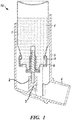
まず、図1を参照すると、これは従来技術のpMDI吸入器15を示しており、2つのシール8、9で適所に押し付けることによって、キャニスター1に取り付けられたバルブ機構が示されている。典型的には、このようなシールは1つのみ必要とされる。キャニスター1は、pMDI装置によって分配される薬剤のバルク配合物4を含む。この充填されたキャニスター、及びバルブのアセンブリが、作動装置5のバルブ座部2に挿入される。バルブ座部2はノズル3を有し、これを通じて薬剤が分配される。作動装置5はまた、マウスピース6を含み、ユーザは、キャニスター1と作動装置5とを互いに押し付けている間に、これを通じて吸入する。ユーザが容易に薬剤を吸入できるように、マウスピース6は、ノズル3と実質的に位置合わせされている。 Referring first to FIG. 1, this shows a prior art pMDI inhaler 15 showing the valve mechanism attached to the canister 1 by pressing it in place with two seals 8,9. Typically only one such seal is required. The canister 1 contains a bulk formulation 4 of the drug dispensed by the pMDI device. This filled canister and valve assembly is inserted into the valve seat 2 of the actuator 5. The valve seat 2 has a nozzle 3 through which the drug is dispensed. Actuator 5 also includes a mouthpiece 6 through which the user inhales while canister 1 and actuator 5 are pressed together. The mouthpiece 6 is substantially aligned with the nozzle 3 so that the user can easily inhale the medicine.
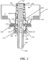
ここで図2を参照し、バルブ機構100は、バルブ100をキャニスター1(図1に示される)に押し付ける手段をもたらすフェルール10内に取り付けられた、バルブ本体110を備える。配合物4は、バルブ本体110内に設けられた入口120を介して、バルブ内に入ることができる。バルブステム130は、バルブ本体110内に設けられ、少なくとも第1位置と第2位置との間で、バルブ本体110に対して可動である。第1位置は、図2に示されるような「停止」位置を含むことがあり、第2位置は、図3に示されるような「分配」位置を含むことがある。
Referring now to FIG. 2, the
バルブステム130は、バルブ本体110内において、その端部150と、バルブステム130上に形成された第1環状肩部160との間に配置される、ばね要素140によって、第1位置に付勢されている。この実施形態において、ばね要素140は圧縮バネを含むが、バルブステム130を第1位置に付勢するために他の種類のばねを使用できることが容易に理解される。
The
図2に示される実施形態において、バルブステム130は、計量前領域170が形成される、第1部分を有する。計量前領域170は、第1位置にあるときに、バルブ本体110の入口120と流体連通する入口180と、実質的に環状である計量チャンバ200と流体連通する出口190とを有する。図示されるように、上記の小型バルブシール210が、計量前領域170の入口180に設けられている。
In the embodiment shown in FIG. 2, the
この実施形態において、計量前領域170への入口180、及びここからの出口190のそれぞれが、側壁220の、直径方向反対側に位置しており、その間に実質的に「S字型」の経路を効果的に画定している。矢印230は、バルブが配合物を収容するキャニスターに取り付けられるときに、バルブ内でバルク配合物4が位置する場所から、計量チャンバ200まで(計量前領域170の入口180の小型バルブシール210を通り、計量前領域170自体を通り、出口190を通って計量チャンバ200まで)の流体の流れを示している。しかしながら、計量前領域170の入口180及び出口190を、側壁220の同じ側に形成し、計量前領域170を画定し、その間に「C字型」経路が有効に画定されるようにできることは理解される。用語「S字型」及び「C字型」は、図2に示されるバルブ100の向きに従う。バルブ100の向き、並びに、バルブステム130の側壁220に対する入口180及び出口190の位置に従って、他の形状が形成されてもよいことが理解される。
In this embodiment, each of the inlet 180 to the
図示されるように、第1シール要素240は、バルブステム130の側壁220の周囲に配置され、バルブ本体110の環状部分250内に配置され、バルブ本体の環状部分は、例えば、圧着、接着など、任意の好適な手段によって、フェルール10内に保持される。第2シール要素260もまた、バルブステム130の側壁220の周囲に配置され、フェルール10の閉鎖端30と、バルブ本体110との間に位置付けられる。第1シール要素240及び第2シール要素260は、バルブ本体110の部分270と共に、バルブステム130周囲に実質的に環状の計量チャンバ200を画定する。
As shown, the
バルブステム130はまた、分配チャネル280が形成される第2部分を有し、分配チャネルは、実質的にバルブステム130の長手方向軸(図示されない)に沿って、バルブステム130の側壁220に位置する入口290から、その遠位端に位置する出口300まで延びるようにして、形成される。
The valve stem 130 also has a second portion in which a
第2環状肩部310が、バルブステム130の第2部分の側壁220上に設けられ、これは、バルブ本体110に対して、バルブステム130の第1位置を画定するよう機能する(これは以下でより詳細に記載される)。
A second
バルブステム130が第2位置にあるとき(図3)、第1シール要素240は、計量チャンバ200を計量前領域170から分離するように作用し、第1位置にあるとき、第2シール要素260は、計量チャンバ200を、バルブステム130の第2部分にある分配チャネル280から分離するように動作し、このとき第2環状肩部310は、図示されるように、第2シール要素260に当接している。
When the
バルブステム130の遠位端は、キャニスター1が取り付けられる作動装置内に形成されたバルブ座部2に接続可能であり(図1に示される)、バルブ座部は、それを通じて計量された用量が分配される、ノズル3を有する。
The distal end of the
図示されるようにバルブ本体110が第1位置と第2位置との間で移動する際、その内壁320によって、第1環状肩部160が効果的に案内されるとき、環状空間330がバルブ本体110とバルブステム130との間に形成され、バルブ本体110の入口120と常に流体連通する。バルブステム130が第1位置にあるか第2位置にあるかにより、環状空間330の容積は可変である。図2に示されるように、バルブステム130は第1位置に位置し、第2環状肩部310は第2シール要素260に当接し、環状空間330の容積は最小になっている。
As shown, when the
図2に示され、先に記載されたように、小型バルブシール210が計量前領域170への入口180に位置している。しかしながら、小型バルブシール210を、計量前領域170への入口経路内の他の位置に配置することも可能である。
As shown in FIG. 2 and described above, a small valve seal 210 is located at the inlet 180 to the
ここで図3を参照し、上記の構成要素は同じ番号を付され、再び詳細に記載されることはない。 Referring now to FIG. 3, the above components are numbered the same and will not be described in detail again.
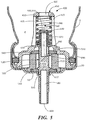
図3において、バルブステム130は、分配チャネル280の入口290が計量チャンバ200と流体連通する、第2又は「分配」位置にあるものとして示されている。これは、患者が吸入するために、バルブステム130の遠位端が挿入される作動装置のノズル及びマウスピース(図示されない)を介して、薬剤の計量された用量が移送されることを可能にする。この位置において、ばね要素140は、第1環状肩部160によって、バルブ本体110の端部150に対して圧迫され、第2環状肩部310は第1シール要素240に当接する。ここで流体が、バルク配合物(図示されない)から、バルブ本体110の入口120を通じて、バルブ本体110とバルブステム130との間に形成される環状空間330内へと流れる。流体はまた、計量前領域170の入口180及び出口190両方が、環状空間330内にあるので、環状空間330から、計量前領域170を通って、環状空間330へと戻るように、流れる。
In FIG. 3, the
ここで、バルブステム130は、第2位置に位置し、第2環状肩部310は、第1シール要素240に当接し、環状空間330の容積は最大になっている。
Here, the
図4は図2と同様であるが、第2小型バルブシール350が、計量前領域170の出口190に設けられるものとして例示されている。図2及び図3に先に記載された構成要素は、同じ参照番号を有し、ここでは再び詳細に記載されることはない。同様の構成要素は、「ダッシュ記号」を付して、同じ参照番号を有しており、例えば、バルブステム130’は、バルブステム130と同様である。
FIG. 4 is similar to FIG. 2, but the second
第2小型バルブシール350は、計量前領域170の出口190に位置するものとして示されているが、第2小型バルブシールは、計量前領域170の出口経路に位置してもよいことが容易に理解される。
Although the second
第1小型バルブシール210及び第2小型バルブシール350がそれぞれ、計量前領域170の入口180及び出口190に位置しない場合、これらを入口180及び出口190に対して位置決めするために、スペーサ(図示されない)を使用してもよい。このように、第1小型バルブシール201及び第2小型バルブシール350はそれぞれ、計量前領域170への入口内、及びここからの出口内に位置してもよい。
If the first small valve seal 210 and the second
上記のように、第2小型バルブシール350を設けることにより、第1又は「停止」位置において、計量前領域が、計量チャンバから効果的に分離される。2つの小型バルブシールが実装される場合、計量前領域170の完全な分離、すなわち、入口180におけるバルク配合物(図示されない)からの、及び出口190における計量チャンバ200からの分離が達成される。
As described above, the provision of the second
第1位置又は「停止」位置以外の場所においては、小型バルブシールの一方が、バルク配合物(図示されない)及び/又は計量チャンバ200からの、計量前領域170の分離をもたらさない場合があることが、容易に理解される。
In locations other than the first or “stop” position, one of the small valve seals may not result in separation of the
図5は、図1に示されるのと同様の方法で、pMDI装置のキャニスター1に取り付けられるものとして示される、バルブ機構400の別の実施形態を例示している。キャニスター1は、pMDI装置によって分配される薬剤のバルク配合物4を含む。バルブ機構400は、フェルール10内に取り付けられ、入口415及び420を介してバルク配合物4に接続された、バルブ本体410を備え、入口を通じてバルク配合物がバルブ本体410の空間630に入る。入口415及び入口420はそれぞれ、バルブ本体410の外周壁面及び遠位端に形成される。バルブステム430は、バルブ本体410内に設けられ、少なくとも第1位置と第2位置との間で、バルブ本体410に対して可動である。第1位置は、図5に図示されるように「停止」位置を含み、第2位置は「分配」位置(図示されない)を含み得るがこれは、図3を参照して先に記載されるように、計量チャンバから薬剤が分配されるときに対応する。
FIG. 5 illustrates another embodiment of the
バルブステム430は、バルブ本体410内において、その端部450と、バルブステム430上に担持された第1環状肩部460との間に位置する、ばね要素440によって、第1位置に付勢されている。端部450は、バルブ本体410内に入口420を画定する。
The
図5に示される実施形態において、バルブステム430は、計量前領域470が形成される、第1部分を有する。計量前領域470は、バルブ本体410の入口415、420と流体連通する入口480と、図示されるように第1位置にあるときに、実質的に環状の計量チャンバ500と流体連通する出口490とを有する。図示されるように、上記の小型バルブシール510が、計量前領域470の入口480に設けられている。
In the embodiment shown in FIG. 5, the
この実施形態において、計量前領域470への入口480は、バルブステム430の近位端に位置し、計量前領域470からの出口490は、側壁520に位置する。この実施形態において、入口480と出口490との間の、計量前領域470を通じた経路は、その間に実質的に「L字型」の経路を有効に画定する。矢印530は、バルク配合物4から、計量チャンバ500まで(計量前領域470の入口480の小型バルブシール510を通り、計量前領域470自体を通り、出口490を通って計量チャンバ500まで)の流体の流れを示している。用語「L字型」は、バルブ400の向きに従っている。
In this embodiment, the inlet 480 to the
図示されるように、第1シール要素540は、バルブステム430の側壁520の周囲に位置し、バルブ本体410の環状部分550内に位置し、バルブ本体の環状部分は、第1シール要素540が挿入される凹部を含んでいる。第2シール要素560はまた、バルブステム430の側壁520の周囲に位置し、フェルール10の閉鎖端50と、バルブステム430との間に位置付けられている。第1シール要素540及び第2シール要素560は、バルブ本体410の部分570と共に、バルブステム430周囲に実質的に環状の計量チャンバ500を画定する。
As shown, the
バルブ本体410の部分570はまた、図示されるように、第1シール要素540及び第2シール要素560の両方を、その対応する位置に保持するように機能する。
The
バルブステム430はまた、分配チャネル580が形成される第2部分を有し、分配チャネルは、実質的にバルブステム430の長手方向軸(図示されない)に沿って、バルブステム430の側壁520に位置する入口590から、その遠位端に位置する出口600まで延びるようにして、形成される。
The valve stem 430 also has a second portion in which a
第2環状肩部610が、バルブステム430の第2部分の側壁520上に設けられ、これは、バルブ本体410に対して、バルブステム430の第1位置を画定するよう機能する(これは以下でより詳細に記載される)。
A second
バルブステム430が第2位置にあるとき(図示されない)、第1シール要素540は、計量チャンバ500を計量前領域470から分離するように動作し、第1位置にあるとき、第2シール要素560は、計量チャンバ500を、バルブステム430の第2部分にある分配チャネル590から分離するように動作し、このとき第2環状肩部610は、図示されるように、第2シール要素560に当接している。図示されないが、バルブステム430が第2位置にあるとき、第2環状肩部610は、第1シール要素540に当接し得ることが容易に理解される。
When the
バルブステム430の遠位端は、キャニスター1が取り付けられる作動装置内に形成されたバルブ座部(図示されない)に接続可能であり、バルブ座部は、それを通じて計量された用量が分配される、ノズル(やはり図示されない)を有する。
The distal end of the
図示されるように、バルブ本体410とバルブステム430との間に空間630が形成され、バルブ本体410の入口415、420と常に流体連通している。バルブステム430が第1位置にあるか、第2位置にあるかにかかわらず、空間630の容積は実質的に同じである。
As shown, a
図5に示され、先に記載されたように、小型バルブシール510が計量前領域470への入口480に位置している。しかしながら、小型バルブシール510を、計量前領域470への入口経路内の他の位置に配置することも可能である。
As shown in FIG. 5 and described above, a small valve seal 510 is located at the inlet 480 to the
図5に図示される実施形態において、第1環状肩部460は、バルブステム430の一部として直接形成されず、バルブステム430の近位端に担持されるキャップ640上に形成される。別の実施形態(図示されない)において、第1環状肩部460は、バルブステム430の一部として形成され得ることが理解される。
In the embodiment illustrated in FIG. 5, the first
第2、又は「分配」位置(図示されない)において、バルブステム430は、ばね要素440の作用に対して、バルブ本体410の端部450の方に押され、これによって分配チャネル580の入口590は、計量チャンバ500と流体連通する。これは、患者が吸うために、バルブステム430の遠位端が挿入される作動装置のノズル及びマウスピース(図示されない)を介して、薬剤の計量された用量が移送されることを可能にする。
In a second, or “distribution” position (not shown), the
この位置において、ばね要素440は、第1環状肩部460によって、バルブ本体410の端部450に対して圧迫され、第2環状肩部610は第1シール要素540に当接し得る。ここで流体が、バルク配合物4から、バルブ本体410の入口415、420を通じて、バルブ本体410とバルブステム430との間に形成される空間630内へと流れる。空間630の容積は、バルブ本体410内のバルブステム430の位置にかかわらず実質的に同じであるが、バルブステム430の第1部分がより多く空間630内にあることによって、容積の僅かな変化が生じ得ることが理解される。
In this position, the
図6は図5と同様であるが、計量前領域内に2つの小型バルブシールを備える、異なるバルブステムが設けられた、別のバルブ機構700を例示している。図5を参照して記載される構成要素は、同じ参照番号を有し、ここで再び詳細に記載されることはない。
FIG. 6 is similar to FIG. 5, but illustrates another
バルブ機構700は、フェルール10内に取り付けられ、入口415、420を介して、バルク配合物4に接続された、バルブ本体410を備える。バルブステム730は、バルブ本体410内に設けられ、少なくとも第1位置と第2位置との間で、バルブ本体410に対して可動である。第1位置は、図6に示されるような「停止」位置を含むことがあり、第2位置は、(図7に示されるような)「分配」位置を含むことがある。
The
バルブステム730は、バルブ本体410内において、その端部450と、バルブステム730上に形成された第1環状肩部760との間に位置する、ばね要素440によって、第1位置に付勢されている。図6に示される実施形態において、バルブステム730は、計量前領域770が形成される、第1部分を有する。計量前領域770は、バルブ本体410の入口415、420と流体連通する入口780と、図示されるように第1位置にあるときに、実質的に環状の計量チャンバ500と流体連通する出口790とを有する。図示されるように、上記の小型バルブシール810が、計量前領域770の入口780に隣接するように設けられている。この場合、小型バルブシール810は、図5を参照して記載されるように、入口に位置してはおらず、入口780から計量前領域770への入口経路内に位置している。
The
この実施形態において、計量前領域770からの出口790は、バルブステム730の側壁820内に位置している。入口780は、バルブステム730の近位端に位置している。この実施形態において、入口780と出口790との間の、計量前領域770を通じた経路は、その間に実質的に「L字型」の経路を有効に画定する。矢印830は、バルク配合物4から、計量チャンバ500まで(計量前領域770の入口790に隣接する小型バルブシール810を通り、計量前領域770自体を通り、出口790を通って計量チャンバ500まで)の流体の流れを示している。用語「L字型」は、図6に示されるバルブ700の向きに従う。
In this embodiment, the
図示されるように、第1シール要素540は、バルブステム730の側壁820の周囲に位置し、バルブ本体410の環状部分550内に位置し、バルブ本体の環状部分は、第1シール要素540が挿入される凹部を含んでいる。第2シール要素560はまた、バルブステム730の側壁820の周囲に位置し、フェルール10の閉鎖端50と、バルブ本体410の部分570との間に位置付けられている。第1シール要素540及び第2シール要素560は、バルブ本体410の部分570と共に、バルブステム430周囲に実質的に環状の計量チャンバ500を画定する。
As shown, the
バルブ本体410の部分570はまた、図示されるように、第1シール要素540及び第2シール要素560の両方を、その対応する位置に保持するように機能する。
The
バルブステム730はまた、分配チャネル580が形成される第2部分を有し、分配チャネルは、実質的にバルブステム730の長手方向軸(図示されない)に沿って、バルブステム730の側壁820に位置する入口590から、その遠位端に位置する出口600まで延びるようにして、形成される。
The valve stem 730 also has a second portion in which a
第2環状肩部610が、バルブステム730の第2部分の側壁825上に設けられ、これは、バルブ本体410に対して、バルブステム730の第1位置を画定するよう機能する。
A second
バルブステム730が第2位置にあるとき(図示されない)、第1シール要素540は、計量チャンバ500を計量前領域770から分離するように動作し、第1位置にあるとき、第2シール要素560は、計量チャンバ500を、バルブステム730の第2部分にある分配チャネル580から分離するように動作し、このとき第2環状肩部610は、図示されるように、第2シール要素560に当接している。
When the
上記のように、バルブステム730の遠位端は、キャニスター1が取り付けられる作動装置内に形成されたバルブ座部(図示されない)に接続可能であり、バルブ座部は、それを通じて計量された用量が分配される、ノズル(やはり図示されない)を有する。
As described above, the distal end of the
先に図示され、記載されたように、バルブ本体410とバルブステム730との間に空間630が形成され、バルブ本体410の入口415、420と常に流体連通している。バルブステム730が第1位置にあるか、第2位置にあるかにかかわらず、空間630の容積は実質的に同じである。
As previously shown and described, a
図6に図示され、先に記載されたように、小型バルブシール810は計量前領域770内に、ここへの入口780に隣接するように(すなわち、計量前領域770への入口経路に)、位置している。しかしながら、バルブシール710を、計量前領域770への入口780に、図2〜図4に示される実施形態に関して記載されるのと同様の方法で、配置することも可能である。
As shown in FIG. 6 and described above, the
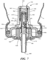
第2、又は「分配」位置(図7に示される)において、バルブステム730は、ばね要素440の作用に対して、バルブ本体410の端部450の方に押され、これによって分配チャネル580の入口590は、計量チャンバ500と流体連通する。これは、患者が吸うために、バルブステム730の遠位端が挿入される作動装置のノズル及びマウスピース(図示されない)を介して、薬剤の計量された用量が移送されることを可能にする。
In the second, or “distribution” position (shown in FIG. 7), the
この位置において、ばね要素440は、第1環状肩部760によって、バルブ本体410の端部450に対して圧迫される。ここで流体が、バルク配合物4から、バルブ本体410の入口415、420を通じて、バルブ本体410とバルブステム730との間に形成される空間630内へと流れる。ここでバルブステム730は、第2位置に位置しており、ここで第2環状肩部610が第1シール要素540に当接し得る。空間630の容積は、バルブ本体410内のバルブステム730の位置にかかわらず実質的に同じであるが、バルブステム730の第1部分がより多く空間630内にあることによって、容積の僅かな変化が生じ得ることが理解される。
In this position, the
図6及び図7に示されるように、第2小型バルブシール850は、計量前領域770への出口790に隣接するように位置している。第1小型バルブシール810及び第2小型バルブシール850は、計量前領域770内に位置しており、第1小型バルブシール810は、入口780から第1スペーサ要素860によって離隔しており、第2小型バルブシール850は、第2スペーサ要素870によって、出口790から離隔している。第1スペーサ要素860及び第2スペーサ要素870はその中央領域に、入口780及び出口790のそれぞれと位置合わせされた、開口部を有する。好ましくは、各スペーサの露出面は、バルブステム730の対応する側壁820、825と同一面上にある。
As shown in FIGS. 6 and 7, the second
両方の小型バルブシールは、入口経路及び出口経路の両方の、計量前領域の内部に位置しているが、代替的に、これらのバルブシールの一方のみが計量前領域内に位置し、他方が入口にあってもよく(図5を参照して記載される)、又は出口にあってもよい(図示されない)ことが、容易に理解される。更なる選択肢として、小型バルブシールのいずれか、又は両方が、対応する入口又は出口(やはり図示されない)に位置してもよい。 Both small valve seals are located inside the pre-metering area, both in the inlet and outlet paths, but alternatively only one of these valve seals is located in the pre-metering area and the other It is readily understood that it may be at the inlet (described with reference to FIG. 5) or at the outlet (not shown). As a further option, either or both of the small valve seals may be located at corresponding inlets or outlets (also not shown).
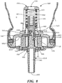
図8は、図5を参照して記載されたものと同様の、別のバルブ機構900を例示しており、ここでは計量前領域への入口は、異なる場所に位置している。図5を参照して記載される構成要素は、同じ参照番号を有している。
FIG. 8 illustrates another
バルブ機構900は、フェルール10内に取り付けられ、入口420を介して、バルク配合物4に接続された、バルブ本体410を備える。バルブステム930は、バルブ本体410内に設けられ、少なくとも第1位置と第2位置との間で、バルブ本体410に対して可動である。第1位置は先に示しかつ記載された「停止」位置を含む。第2位置は「分配」位置(図示されない)を含み得るが、図3及び図7を参照して先に記載されるように、これは計量チャンバから薬剤が分配されるときに対応する。
The
バルブステム930は、バルブ本体410内において、その端部450と、バルブステム930上に形成された第1環状肩部960との間に位置する、ばね要素440によって、第1位置に付勢されている。バルブステム930は、計量前領域970が形成される第1部分を有し、計量前領域970は、バルブ本体410の入口420と流体連通する入口980と、先に図示され、記載されたように第1位置にあるときに、実質的に環状の計量チャンバ500と流体連通する出口990とを有する。
図示されるように、上記の小型バルブシール1010が、計量前領域970の入口980に隣接するように設けられている。この場合、小型バルブシール1010は、図5を参照して記載されるように、入口に位置してはおらず、入口980から計量前領域970への入口経路内に位置している。
As shown, the
この実施形態において、計量前領域970への入口980、及びここからの出口990は、バルブステム930の側壁1020内に位置している。この実施形態において、入口980と出口990との間の、計量前領域970を通じた経路は、その間に実質的に「Z字型」経路を有効に画定する。矢印1030は、バルク配合物4から、計量チャンバ500まで(計量前領域970の入口980に隣接する小型バルブシール1010を通り、計量前領域970自体を通り、出口990を通って計量チャンバ500まで)の流体の流れを示している。用語「Z字型」は、本明細書において使用するとき、バルブ機構900の向きを指す。
In this embodiment, the
図示されるように、第1シール要素540は、バルブステム930の側壁520の周囲に位置し、バルブ本体410の環状部分550内に位置し、バルブ本体の環状部分は、第1シール要素540が挿入される凹部を含んでいる。第2シール要素560はまた、バルブステム930の側壁1020の周囲に位置し、フェルール10の閉鎖端50と、バルブステム930との間に位置付けられている。第1シール要素540及び第2シール要素560は、バルブ本体410の部分570と共に、バルブステム930周囲に実質的に環状の計量チャンバ500を画定する。
As shown, the
バルブ本体410の部分570はまた、図示されるように、第1シール要素540及び第2シール要素560の両方を、その対応する位置に保持するように機能する。
The
バルブステム930はまた、分配チャネル580が形成される第2部分を有し、分配チャネルは、実質的にバルブステム930の長手方向軸(図示されない)に沿って、バルブステム930の側壁1020に位置する入口590から、その遠位端に位置する出口600まで延びるようにして、形成される。
The valve stem 930 also has a second portion in which a
第2環状肩部610が、バルブステム930の第2部分の側壁1020上に設けられ、これは、バルブステムの外側への動きを制限することにより、バルブ本体410に対して、バルブステム930の第1位置を画定するよう機能する。
A second
バルブステム930が第2位置にあるとき(図示されない)、第1シール要素540は、計量チャンバ500を計量前領域970から分離するように動作し、第1位置にあるとき、第2シール要素560は、計量チャンバ500を、バルブステム930の第2部分にある分配チャネル590から分離するように動作し、このとき第2環状肩部610は、図示されるように、第2シール要素560に当接している。図示されないが、バルブステム930が第2位置にあるとき、第2環状肩部610は、第1シール要素540に当接し得ることが容易に理解される。
When the
上記のように、バルブステム930の遠位端は、キャニスター1が取り付けられる作動装置内に形成されたバルブ座部(図示されない)に接続可能であり、バルブ座部は、それを通じて計量された用量が分配される、ノズル(やはり図示されない)を有する。
As described above, the distal end of the
図5を参照して示され、記載されたように、バルブ本体410とバルブステム930との間に空間630が形成され、バルブ本体410の入口420と常に流体連通している。バルブステム930が第1位置にあるか、第2位置にあるかにかかわらず、空間630の容積は実質的に同じである。
As shown and described with reference to FIG. 5, a
図8に図示され、先に記載されたように、小型バルブシール1010は計量前領域970内に、ここへの入口980に隣接するように(すなわち、計量前領域970への入口経路内に)、位置している。スペーサ要素1060は、入口980に位置し、小型バルブシール1010をそこから離隔させている。上記のように、スペーサ要素1060は、その中央領域に、計量前領域970の入口980と位置合わせされた、開口部を有する。しかしながら、小型バルブシール1010を、計量前領域970への入口980に、図2〜図4に示される実施形態に関して記載されるのと同様の方法で、配置することも可能である。
As shown in FIG. 8 and described above, the
第2、又は「分配」位置(図示されない)において、バルブステム930は、ばね要素440の作用に対して、バルブ本体410の端部450の方に押され、これによって分配チャネル580の入口590は、計量チャンバ500と流体連通する。これは、患者が吸うために、バルブステム930の遠位端が挿入される作動装置のノズル及びマウスピース(図示されない)を介して、薬剤の計量された用量が移送されることを可能にする。
In a second, or “distribution” position (not shown), the
この位置において、ばね要素440は、第1環状肩部960によって、バルブ本体410の端部450に対して圧迫され、第2環状肩部610は第1シール要素540に当接し得る。ここで流体が、バルク配合物4から、バルブ本体410の入口415、420を通じて、バルブ本体410とバルブステム930との間に形成される空間630内へと流れる。空間630の容積は、バルブ本体410内のバルブステム930の位置にかかわらず実質的に同じであるが、バルブステム930の第1部分がより多く空間630内にあることによって、容積の僅かな変化が生じ得ることが理解される。
In this position, the
別の実施形態(図示されない)、第2小型バルブシールは、先に図4に示された実施形態を参照して記載されたものと同様の方法で、計量前領域970への出口990に配置することができる。
In another embodiment (not shown), the second small valve seal is placed at the
図5〜図8に示される実施形態に関しては、具体的に記載されなかったが、各場合においてバルブステムは、例示されるバルブステムの外形を形成するために、共に接合される複数の構成部品を含む。あるいは、図示されないが、各場合においてバルブステムは対応する計量前領域の入口及び出口を形成するように適切な開口部を有する、一体型構成要素を備えてもよい。 Although not specifically described with respect to the embodiment shown in FIGS. 5-8, in each case the valve stem is joined together to form the illustrated valve stem profile. including. Alternatively, although not shown, in each case the valve stem may comprise an integral component with appropriate openings to form the corresponding pre-metering region inlet and outlet.
加えて、小型バルブシールは、関連するスペーサ要素と別個であるものとして記載されてきたが、シールは、スペーサ要素と一体に、又はその一部として、形成され得ることが容易に理解される。あるいは、小型バルブシールは、バルブステムと共成形されてもよい。 In addition, although the miniature valve seal has been described as being separate from the associated spacer element, it is readily understood that the seal can be formed integrally with or as part of the spacer element. Alternatively, the small valve seal may be co-molded with the valve stem.
図5〜図8に図示される実施形態は、内壁570の存在を例示しているが、バルブ本体410の壁部は、計量チャンバ500を画定するように好適な形状にし得ることが、容易に理解される。後者の場合において、第1シール要素540及び第2シール要素560を、バルブ本体410内で適所に保持するために、他の手段を設ける必要がある場合がある。
Although the embodiment illustrated in FIGS. 5-8 illustrates the presence of the
Claims (17)
前記ハウジング内に取り付けられ、入口を有するバルブ本体と、
前記バルブ本体内で、少なくとも第1位置と第2位置との間で、バルブ本体に対して可動である、バルブステムと、
前記バルブ本体内に配置され、前記バルブステムを前記第1位置へと付勢するように動作可能である、戻り部材と、
前記バルブステムの第1部分内に形成され、入口ポート及び出口ポートを含む計量前領域であって、前記入口ポートは前記バルブ本体の前記入口に接続されている、計量前領域と、
前記バルブステムと前記バルブハウジングとの間に形成された計量チャンバであって、前記計量前領域の前記出口ポートに接続可能な、計量チャンバと、
前記計量前領域への入口経路内に位置付けられ、計量した用量を前記計量前領域内に保持するように動作可能な、第1用量保持要素であって、前記第1用量保持要素を通じて双方向への流体の移送をもたらす、第1用量保持要素と、
前記バルブステムの第2部分内に形成され、分配入口及び分配出口を有する、分配チャネルであって、前記分配入口は前記第2位置において前記計量チャンバに接続可能である、分配チャネルと、を含む、計量バルブ。 A housing;
A valve body mounted in the housing and having an inlet;
A valve stem movable relative to the valve body at least between a first position and a second position within the valve body;
A return member disposed within the valve body and operable to bias the valve stem to the first position;
A pre-metering region formed in the first portion of the valve stem and including an inlet port and an outlet port, the inlet port connected to the inlet of the valve body;
A metering chamber formed between the valve stem and the valve housing, the metering chamber connectable to the outlet port in the pre-metering region;
A first dose-holding element positioned in the entrance path to the pre-metering region and operable to hold a metered dose in the pre-metering region, bi-directionally through the first dose-holding element A first dose retaining element that provides for the transfer of a fluid;
A distribution channel formed in the second portion of the valve stem and having a distribution inlet and a distribution outlet, wherein the distribution inlet is connectable to the metering chamber in the second position; , Metering valve.
Applications Claiming Priority (3)
| Application Number | Priority Date | Filing Date | Title |
|---|---|---|---|
| GB1503402.8A GB2535796A (en) | 2015-02-27 | 2015-02-27 | Improvements in or relating to metered dose inhalers |
| GB1503402.8 | 2015-02-27 | ||
| PCT/US2016/018848 WO2016137853A1 (en) | 2015-02-27 | 2016-02-22 | Metered dose inhalers |
Publications (2)
| Publication Number | Publication Date |
|---|---|
| JP2018506367A true JP2018506367A (en) | 2018-03-08 |
| JP2018506367A5 JP2018506367A5 (en) | 2019-04-04 |
Family
ID=52876285
Family Applications (1)
| Application Number | Title | Priority Date | Filing Date |
|---|---|---|---|
| JP2017544720A Pending JP2018506367A (en) | 2015-02-27 | 2016-02-22 | Metered dose inhaler |
Country Status (5)
| Country | Link |
|---|---|
| US (1) | US10029845B2 (en) |
| EP (1) | EP3261955B1 (en) |
| JP (1) | JP2018506367A (en) |
| GB (1) | GB2535796A (en) |
| WO (1) | WO2016137853A1 (en) |
Families Citing this family (5)
| Publication number | Priority date | Publication date | Assignee | Title |
|---|---|---|---|---|
| GB2554365B (en) * | 2016-09-22 | 2022-05-04 | Aer Beatha Ltd | Canister and valve |
| US10759648B2 (en) * | 2019-02-04 | 2020-09-01 | Pfennig Reinigungstechnik Gmbh | Cleaning liquid dosing system utilizing a weighted hollow piston to define a dosing volume |
| EP3738677B1 (en) * | 2019-05-16 | 2021-12-08 | Brill Engines, S.L. | A device suitable for dispensing liquid substances |
| US20220401663A1 (en) * | 2021-06-18 | 2022-12-22 | Loop Laboratories, LLC | Compact atomizer |
| US11877848B2 (en) | 2021-11-08 | 2024-01-23 | Satio, Inc. | Dermal patch for collecting a physiological sample |
Citations (3)
| Publication number | Priority date | Publication date | Assignee | Title |
|---|---|---|---|---|
| JPH07500426A (en) * | 1990-11-30 | 1995-01-12 | シーバ ヴィジョン コーポレーション | Contact lens container exhaust system |
| JPH10118178A (en) * | 1996-10-24 | 1998-05-12 | Jms Co Ltd | Check valve for medical treatment |
| GB2345279A (en) * | 1998-12-29 | 2000-07-05 | Bespak Plc | Metering valve for a dispensing apparatus |
Family Cites Families (13)
| Publication number | Priority date | Publication date | Assignee | Title |
|---|---|---|---|---|
| BE793319A (en) * | 1971-12-28 | 1973-06-27 | Ciba Geigy | AEROSOL DISPENSER FOR FLUID PRODUCTS |
| US4135648A (en) * | 1977-10-26 | 1979-01-23 | Summit Packaging Systems, Inc. | Metering valve for pressurized dispensing containers |
| US4919312A (en) * | 1986-01-30 | 1990-04-24 | Bespak Plc | Collapsible chamber metering valves |
| US4819834A (en) * | 1986-09-09 | 1989-04-11 | Minnesota Mining And Manufacturing Company | Apparatus and methods for delivering a predetermined amount of a pressurized fluid |
| FR2615172B1 (en) * | 1987-05-11 | 1989-08-18 | Valois | DOSER AEROSOL VALVE FOR USE IN THE REVERSE POSITION |
| GB9420971D0 (en) * | 1994-05-06 | 1994-12-07 | Minnesota Mining & Mfg | Aerosol valves |
| GB9805938D0 (en) * | 1998-03-19 | 1998-05-13 | Glaxo Group Ltd | Valve for aerosol container |
| US6454140B1 (en) * | 2000-07-28 | 2002-09-24 | 3M Innovative Properties Companies | Metered dose dispensing aerosol valve |
| WO2004110335A1 (en) * | 2003-06-10 | 2004-12-23 | Astellas Pharma Inc. | Aerosol preparation comprising sealed container and enclosed therein aerosol composition containing macrolide compound |
| FR2860502B1 (en) * | 2003-10-07 | 2007-09-14 | Valois Sas | DOSING VALVE AND DEVICE FOR DISPENSING FLUID PRODUCT COMPRISING SUCH A VALVE |
| FR2860503B1 (en) * | 2003-10-07 | 2007-11-02 | Valois Sas | VALVE AND DISPENSING DEVICE COMPRISING SUCH A VALVE. |
| GB2417479B (en) * | 2004-08-26 | 2006-09-13 | Bespak Plc | Improvements in metering valves for pressurised dispensing containers |
| PT2485966T (en) * | 2009-10-09 | 2016-07-08 | The Salford Valve Company Ltd | Liquid dispensing apparatus |
-
2015
- 2015-02-27 GB GB1503402.8A patent/GB2535796A/en not_active Withdrawn
-
2016
- 2016-02-22 WO PCT/US2016/018848 patent/WO2016137853A1/en active Application Filing
- 2016-02-22 EP EP16706771.9A patent/EP3261955B1/en active Active
- 2016-02-22 US US15/552,401 patent/US10029845B2/en active Active
- 2016-02-22 JP JP2017544720A patent/JP2018506367A/en active Pending
Patent Citations (3)
| Publication number | Priority date | Publication date | Assignee | Title |
|---|---|---|---|---|
| JPH07500426A (en) * | 1990-11-30 | 1995-01-12 | シーバ ヴィジョン コーポレーション | Contact lens container exhaust system |
| JPH10118178A (en) * | 1996-10-24 | 1998-05-12 | Jms Co Ltd | Check valve for medical treatment |
| GB2345279A (en) * | 1998-12-29 | 2000-07-05 | Bespak Plc | Metering valve for a dispensing apparatus |
Also Published As
| Publication number | Publication date |
|---|---|
| GB2535796A (en) | 2016-08-31 |
| GB201503402D0 (en) | 2015-04-15 |
| US10029845B2 (en) | 2018-07-24 |
| EP3261955A1 (en) | 2018-01-03 |
| WO2016137853A1 (en) | 2016-09-01 |
| US20180057248A1 (en) | 2018-03-01 |
| EP3261955B1 (en) | 2020-11-11 |
Similar Documents
| Publication | Publication Date | Title |
|---|---|---|
| JP2018506367A (en) | Metered dose inhaler | |
| US20190247607A1 (en) | Inhalator | |
| AU2013308230B2 (en) | An inhaler | |
| KR102268162B1 (en) | Inhaler | |
| MX2023005112A (en) | Smart valved holding chamber. | |
| US20110068133A1 (en) | Device for dispensing a liquid in a tank | |
| KR19980702911A (en) | Aerosol valve | |
| US10821241B2 (en) | Housing for an inhalation device and inhalation device for orally administering a pharmaceutical medium | |
| CN107645962B (en) | Filter injection needle assembly for syringe | |
| US10729862B2 (en) | Inhaler device | |
| US20240050670A1 (en) | Drug delivery systems and related methods | |
| BR112016005076B1 (en) | distribution system | |
| EP2992967B1 (en) | Medicament dispenser | |
| WO2018051371A2 (en) | Powder dispenser | |
| CN109641112B (en) | Outer cap of liquid medicine injection device | |
| CN109641692B (en) | Pressurized container | |
| JP5118650B2 (en) | Mouthpiece for fluid dispenser device | |
| US8408431B2 (en) | Valve | |
| US20220347405A1 (en) | Inhaler | |
| JP7250740B2 (en) | Metering valves, high-pressure vessels and asthma treatment devices | |
| US20220347409A1 (en) | Device for inhalation-synchronised dispensing of a fluid product |
Legal Events
| Date | Code | Title | Description |
|---|---|---|---|
| A521 | Request for written amendment filed |
Free format text: JAPANESE INTERMEDIATE CODE: A523 Effective date: 20190219 |
|
| A621 | Written request for application examination |
Free format text: JAPANESE INTERMEDIATE CODE: A621 Effective date: 20190219 |
|
| A131 | Notification of reasons for refusal |
Free format text: JAPANESE INTERMEDIATE CODE: A131 Effective date: 20200121 |
|
| A521 | Request for written amendment filed |
Free format text: JAPANESE INTERMEDIATE CODE: A523 Effective date: 20200402 |
|
| A131 | Notification of reasons for refusal |
Free format text: JAPANESE INTERMEDIATE CODE: A131 Effective date: 20200609 |
|
| A02 | Decision of refusal |
Free format text: JAPANESE INTERMEDIATE CODE: A02 Effective date: 20210112 |