JP2018503573A - Method for loading into a pocket of a transfer device in the form of a suspension conveyor and device for carrying out the method - Google Patents
Method for loading into a pocket of a transfer device in the form of a suspension conveyor and device for carrying out the method Download PDFInfo
- Publication number
- JP2018503573A JP2018503573A JP2017535027A JP2017535027A JP2018503573A JP 2018503573 A JP2018503573 A JP 2018503573A JP 2017535027 A JP2017535027 A JP 2017535027A JP 2017535027 A JP2017535027 A JP 2017535027A JP 2018503573 A JP2018503573 A JP 2018503573A
- Authority
- JP
- Japan
- Prior art keywords
- fabric web
- transfer
- pockets
- loading
- Prior art date
- Legal status (The legal status is an assumption and is not a legal conclusion. Google has not performed a legal analysis and makes no representation as to the accuracy of the status listed.)
- Pending
Links
- 238000000034 method Methods 0.000 title claims abstract description 25
- 239000000725 suspension Substances 0.000 title claims abstract description 12
- 239000004744 fabric Substances 0.000 claims abstract description 63
- 230000001360 synchronised effect Effects 0.000 claims description 2
- 239000000463 material Substances 0.000 abstract 1
- 230000008878 coupling Effects 0.000 description 6
- 238000010168 coupling process Methods 0.000 description 6
- 238000005859 coupling reaction Methods 0.000 description 6
- 230000007246 mechanism Effects 0.000 description 4
- 230000007257 malfunction Effects 0.000 description 2
- 230000007704 transition Effects 0.000 description 2
- 230000006978 adaptation Effects 0.000 description 1
- 238000006073 displacement reaction Methods 0.000 description 1
- 238000005516 engineering process Methods 0.000 description 1
- 238000011144 upstream manufacturing Methods 0.000 description 1
Images


Classifications
-
- B—PERFORMING OPERATIONS; TRANSPORTING
- B65—CONVEYING; PACKING; STORING; HANDLING THIN OR FILAMENTARY MATERIAL
- B65G—TRANSPORT OR STORAGE DEVICES, e.g. CONVEYORS FOR LOADING OR TIPPING, SHOP CONVEYOR SYSTEMS OR PNEUMATIC TUBE CONVEYORS
- B65G17/00—Conveyors having an endless traction element, e.g. a chain, transmitting movement to a continuous or substantially-continuous load-carrying surface or to a series of individual load-carriers; Endless-chain conveyors in which the chains form the load-carrying surface
- B65G17/20—Conveyors having an endless traction element, e.g. a chain, transmitting movement to a continuous or substantially-continuous load-carrying surface or to a series of individual load-carriers; Endless-chain conveyors in which the chains form the load-carrying surface comprising load-carriers suspended from overhead traction chains
-
- B—PERFORMING OPERATIONS; TRANSPORTING
- B65—CONVEYING; PACKING; STORING; HANDLING THIN OR FILAMENTARY MATERIAL
- B65G—TRANSPORT OR STORAGE DEVICES, e.g. CONVEYORS FOR LOADING OR TIPPING, SHOP CONVEYOR SYSTEMS OR PNEUMATIC TUBE CONVEYORS
- B65G19/00—Conveyors comprising an impeller or a series of impellers carried by an endless traction element and arranged to move articles or materials over a supporting surface or underlying material, e.g. endless scraper conveyors
- B65G19/02—Conveyors comprising an impeller or a series of impellers carried by an endless traction element and arranged to move articles or materials over a supporting surface or underlying material, e.g. endless scraper conveyors for articles, e.g. for containers
- B65G19/025—Conveyors comprising an impeller or a series of impellers carried by an endless traction element and arranged to move articles or materials over a supporting surface or underlying material, e.g. endless scraper conveyors for articles, e.g. for containers for suspended articles
-
- B—PERFORMING OPERATIONS; TRANSPORTING
- B65—CONVEYING; PACKING; STORING; HANDLING THIN OR FILAMENTARY MATERIAL
- B65G—TRANSPORT OR STORAGE DEVICES, e.g. CONVEYORS FOR LOADING OR TIPPING, SHOP CONVEYOR SYSTEMS OR PNEUMATIC TUBE CONVEYORS
- B65G47/00—Article or material-handling devices associated with conveyors; Methods employing such devices
- B65G47/34—Devices for discharging articles or materials from conveyor
- B65G47/38—Devices for discharging articles or materials from conveyor by dumping, tripping, or releasing load carriers
-
- B—PERFORMING OPERATIONS; TRANSPORTING
- B65—CONVEYING; PACKING; STORING; HANDLING THIN OR FILAMENTARY MATERIAL
- B65G—TRANSPORT OR STORAGE DEVICES, e.g. CONVEYORS FOR LOADING OR TIPPING, SHOP CONVEYOR SYSTEMS OR PNEUMATIC TUBE CONVEYORS
- B65G47/00—Article or material-handling devices associated with conveyors; Methods employing such devices
- B65G47/34—Devices for discharging articles or materials from conveyor
- B65G47/44—Arrangements or applications of hoppers or chutes
-
- B—PERFORMING OPERATIONS; TRANSPORTING
- B65—CONVEYING; PACKING; STORING; HANDLING THIN OR FILAMENTARY MATERIAL
- B65G—TRANSPORT OR STORAGE DEVICES, e.g. CONVEYORS FOR LOADING OR TIPPING, SHOP CONVEYOR SYSTEMS OR PNEUMATIC TUBE CONVEYORS
- B65G47/00—Article or material-handling devices associated with conveyors; Methods employing such devices
- B65G47/52—Devices for transferring articles or materials between conveyors i.e. discharging or feeding devices
- B65G47/60—Devices for transferring articles or materials between conveyors i.e. discharging or feeding devices to or from conveyors of the suspended, e.g. trolley, type
- B65G47/61—Devices for transferring articles or materials between conveyors i.e. discharging or feeding devices to or from conveyors of the suspended, e.g. trolley, type for articles
-
- B—PERFORMING OPERATIONS; TRANSPORTING
- B65—CONVEYING; PACKING; STORING; HANDLING THIN OR FILAMENTARY MATERIAL
- B65G—TRANSPORT OR STORAGE DEVICES, e.g. CONVEYORS FOR LOADING OR TIPPING, SHOP CONVEYOR SYSTEMS OR PNEUMATIC TUBE CONVEYORS
- B65G9/00—Apparatus for assisting manual handling having suspended load-carriers movable by hand or gravity
- B65G9/004—Loading or unloading arrangements
-
- B—PERFORMING OPERATIONS; TRANSPORTING
- B65—CONVEYING; PACKING; STORING; HANDLING THIN OR FILAMENTARY MATERIAL
- B65G—TRANSPORT OR STORAGE DEVICES, e.g. CONVEYORS FOR LOADING OR TIPPING, SHOP CONVEYOR SYSTEMS OR PNEUMATIC TUBE CONVEYORS
- B65G2201/00—Indexing codes relating to handling devices, e.g. conveyors, characterised by the type of product or load being conveyed or handled
- B65G2201/02—Articles
- B65G2201/0235—Containers
- B65G2201/0238—Bags
Abstract
サスペンションコンベヤの形態をとる移送装置のポケット(20a〜20c)を荷積みする方法が開示され、移送装置は1以上のキャリッジないしはトロリーを備え、トロリーは、その軌道(15a,15b)に移動可能に取り付けられ、各トロリーには、被移送物(19b)を受容するためのポケットが配置され、ポケットは、開放状態では平面状となり、両端でトロリーに固定された少なくとも1枚の可撓性布地ウェブによって形成されて移送ループを形成する。布地ウェブは、少なくとも一端でトロリーに解放可能に固定される。本方法は、(a)閉鎖ポケットを進め、(b)布地ウェブの一端とトロリーとの固定を解除してポケットを開放し、(c)開放ポケットに移送されるべき被移送物を積み込み、(d)布地ウェブの一端をトロリーに固定してポケットを閉鎖し、(e)荷積みされ閉鎖ポケットを更に移送することを含む。【選択図】図5fA method for loading a transfer device pocket (20a-20c) in the form of a suspension conveyor is disclosed, the transfer device comprising one or more carriages or trolleys, the trolley being movable on its track (15a, 15b). Attached and each trolley is provided with a pocket for receiving the object to be transported (19b), the pocket being planar when open and fixed at both ends to the trolley at least one flexible fabric web To form a transfer loop. The fabric web is releasably secured to the trolley at least at one end. The method includes (a) advancing a closed pocket, (b) unlocking one end of the fabric web and the trolley to open the pocket, (c) loading the material to be transferred into the open pocket, d) securing one end of the fabric web to the trolley to close the pocket, and (e) loading and further transferring the closed pocket. [Selection] Figure 5f
Description
本発明は、搬送技術の分野に関する。本発明は、請求項1の前文に記載のサスペンションコンベヤの形態をとる移送装置のポケット(袋状体)に荷積みする方法に関する。 The present invention relates to the field of transport technology. The present invention relates to a method for loading into a pocket of a transfer device in the form of a suspension conveyor according to the preamble of claim 1.
本発明はさらに、上記方法を実行するための装置に関する。 The invention further relates to an apparatus for performing the method.
従来技術では、搬送されるべき物品が移送ポケットによって受容される多種多様のサスペンションコンベヤが知られており、移送ポケットは、比較的複雑な態様で構成され、かつ複雑な開閉機構を備えている。この開閉機構は、特に、多くの個別のポケットを有する大型搬送システムの場合、一方では、新しいシステムを設置するときにコストの著しい増大をもたらし、他方では、連続運転において誤動作または完全な機能不全の影響をより大きく受ける可能性がある。 In the prior art, a wide variety of suspension conveyors are known in which articles to be transported are received by transfer pockets, which are constructed in a relatively complex manner and equipped with complex opening and closing mechanisms. This opening and closing mechanism, especially in the case of large transport systems with many individual pockets, on the one hand leads to a significant increase in costs when installing a new system, and on the other hand, malfunctions or complete malfunctions in continuous operation. Can be more affected.
独国特許出願公開第102008061685号明細書は、サスペンションコンベヤシステム内で移送される移送ポケット用のローディングステーションを開示しており、このローディングステーションは、移送ポケット用の上側供給レールと、移送ポケットを下部ローディング位置に供給するための、供給レールに隣接する垂直コンベヤと、ローディング位置で移送ポケットを開放するための装置と、ローディング位置から移送ポケットを送り出すための、垂直コンベヤに隣接する下側送出しレールと、を備える。 German Offenlegungsschrift 102008061685 discloses a loading station for a transfer pocket to be transferred in a suspension conveyor system, which includes an upper supply rail for the transfer pocket and a lower transfer pocket. A vertical conveyor adjacent to the supply rail for feeding to the loading position, a device for opening the transfer pocket at the loading position, and a lower delivery rail adjacent to the vertical conveyor for delivering the transfer pocket from the loading position And comprising.
独国特許出願公開第102008026720号明細書は、支持壁および底側壁を備える移送ポケットを開示しており、支持壁は、その上部領域に支持カップリングおよび枢動可能クランプを備え、支持壁の下部領域に少なくとも1つのカップリングを備え、支持壁の上部領域にカップリングを開くための手段およびカップリングを閉じるための手段を備え、底側壁は、少なくとも下部領域内で可撓性であり、底側壁の下部領域内で枢動可能クランプに連結され、底側壁の下部領域内で、少なくとも1つのカップリング内に受容するためのカウンタカップリング手段を備える。 DE 102008026720 discloses a transfer pocket comprising a support wall and a bottom wall, the support wall comprising a support coupling and a pivotable clamp in its upper region, the lower part of the support wall Comprising at least one coupling in the region, means for opening the coupling in the upper region of the support wall and means for closing the coupling, the bottom side wall being flexible in at least the lower region, Counter coupling means connected to the pivotable clamp in the lower region of the side wall and received in the at least one coupling in the lower region of the bottom side wall.
独国特許出願公開第102011101987号明細書は、搬送システム、特にサスペンション搬送システム内で被搬送物を搬送するための移送ポケットを開示しており、移送ポケットは、搬送システムのコンベヤベルト上で受容するために構成されたキャリヤ部分と被移送物を受容するためのローディング補助器具とを備え、ローディング補助器具は、クランプ部付きのハンドリングタブを有する閉鎖フラップを備え、キャリヤ部分は、クランプレバー付きのクランプ装置を備え、クランプレバーは、保持力がクランプ部に作用する保持位置と解放位置との間で変位することができ、クランプレバーは、受容された被搬送物がその重量により保持力の増大をもたらすように、保持位置でクランプ部に連結される。 German Offenlegungsschrift DE 102 01 110 1987 discloses a transport pocket for transporting a transported object in a transport system, in particular a suspension transport system, the transport pocket being received on a conveyor belt of the transport system. And a loading aid for receiving an object to be transported, the loading aid comprising a closing flap having a handling tab with a clamping part, the carrier part being a clamp with a clamping lever The clamp lever can be displaced between a holding position where a holding force acts on the clamp part and a release position, and the clamp lever can increase the holding force due to the weight of the received object. It is connected to the clamp part in the holding position to bring about.
独国特許出願公開第102012108757号明細書は、物品を懸垂移送するためのサスペンション搬送装置用の支持ポケットに関し、支持ポケットは、サスペンション搬送装置から垂下されて移送されるために、保持フレームと、保持フレームに吊るされかつ移送されるべき物品が受容されることが可能であるポケットポーチと、保持フレームに連結されかつ支持ポケットがサスペンション搬送装置に吊るされることを可能にするサスペンション要素と、を備える。ポケットポーチは、第1のポーチ部および第2のポーチ部を有し、第1のポーチ部および第2のポーチ部は、保持フレームに連結される第1のポーチ端部と保持フレームとは反対側の第2の端部とを備え、第2のポーチ端部はジョイント機構によって互いに連結されており、ジョイント機構は、物品を送る場合にポケットポーチには2つのポーチ端部の間に形成される出口開口が設けられるように、第2のポーチ端部が互いに離間されて配置されるアンローディング位置にすることができ、また、出口開口が閉鎖され、ポケットポーチが物体を受容することができるように、第2のポーチ端部が互いに隣接して配置されるローディング位置にすることができる。 DE-A-10210210757 relates to a support pocket for a suspension transport device for suspending and transporting articles, the support pocket being suspended and transported from the suspension transport device, A pocket pouch that is capable of receiving articles to be suspended and transported by the frame, and a suspension element that is connected to the holding frame and that allows the support pocket to be suspended from the suspension transport device. The pocket pouch has a first pouch portion and a second pouch portion, and the first pouch portion and the second pouch portion are opposite to the first pouch end connected to the holding frame and the holding frame. And the second pouch end is connected to each other by a joint mechanism, which is formed between the two pouch ends in the pocket pouch when feeding an article. The second pouch end can be in an unloading position, spaced apart from each other, so that an outlet opening is provided, and the outlet opening is closed so that the pocket pouch can receive objects. As such, it can be in a loading position where the second pouch ends are positioned adjacent to each other.
独国特許出願公開第102013205172号明細書は、被移送物を懸垂移送するための移送ポケットを開示している。移送ポケットは剛性キャリング壁を有し、剛性キャリング壁は、この壁の上部において移送位置で、移送ポケットを運ぶためのキャリング要素に吊り下げられた形で連結される。可撓性物品保持壁がキャリング壁と共にキャリングポケットを形成し、キャリングポケットは、移送ポケットの少なくとも移送位置で2つの対向する側面に向かって下方に閉鎖される。キャリング壁は、移送位置での上部壁連結部と移送位置での下部壁連結部との間の保持壁に連結され、したがって、2つの壁連結部の間のウェブ形状保持壁の長さが異なる被移送物の移送に可変に適合することができる。移送ポケットの設計は、保持壁のこの縦適合が、2つの連結部の少なくとも一方の領域においてキャリング壁に対する保持壁の相対変位によって起こるようになっている。 German Offenlegungsschrift DE 102 01 320 5172 discloses a transfer pocket for the suspended transfer of an object to be transferred. The transfer pocket has a rigid carrying wall, which is connected in a suspended manner to a carrying element for carrying the transfer pocket at the transfer position at the top of this wall. The flexible article retaining wall forms a carrying pocket with the carrying wall, and the carrying pocket is closed downward toward two opposing sides at least at the transfer position of the transfer pocket. The carrying wall is connected to the holding wall between the upper wall connection at the transfer position and the lower wall connection at the transfer position, and thus the length of the web shape holding wall between the two wall connections is different. It can be variably adapted to the transfer of the object to be transferred. The design of the transfer pocket is such that this vertical adaptation of the holding wall occurs due to the relative displacement of the holding wall with respect to the carrying wall in at least one region of the two connections.
新規な移送装置が、2015年1月26日に出願されたスイス特許出願第00089/15号明細書に開示されており、横方向に開放するポケットが布地ウェブからその両端にて吊り下げられることによって形成されて、ループを形成し、前記ポケットは、キャリッジに吊支されて走行レール上で移動することができる。ポケットは、布地ウェブの一端の引っ掛けられた状態(「掛合」状態)が解除されることによって開放され、布地ウェブのその一端がそれに対応して引っ掛けられる(掛合される)ことによって再び閉鎖される。 A new transfer device is disclosed in Swiss patent application No. 00899/15 filed on Jan. 26, 2015, with laterally open pockets suspended from the fabric web at both ends. To form a loop, and the pocket can be suspended on a carriage and moved on a traveling rail. The pocket is opened by releasing the hooked state (“hanging” state) of one end of the fabric web and closed again by correspondingly hooking (hooking) one end of the fabric web. .
したがって、本開示の目的は、かかるポケットに自動的に荷積みする(被移送物を積み込む)方法を提供するとともに、この方法を実行するための対応する装置を提供することである。 Accordingly, it is an object of the present disclosure to provide a method for automatically loading (loading objects to be transferred) into such a pocket and to provide a corresponding apparatus for performing this method.
この目的および他の目的は、請求項1および請求項9の特徴によって達成される。 This and other objects are achieved by the features of claims 1 and 9.
サスペンションコンベヤの形態をとる移送装置のポケットに荷積みする本発明による方法が提供され、移送装置は1つまたは複数のキャリッジ(トロリー)を備え、キャリッジは、走行レールに、当該走行レール方向に移動可能に取り付けられ、垂下したポケットが被移送物を受容することができるようにキャリッジに配置され、ポケットは少なくとも1枚の可撓性布地ウェブによって形成され、可撓性布地ウェブは開放状態では平面状となり、両端でキャリッジに固定されて、垂下したキャリングループおよび/または移送ループを形成し、布地ウェブは、布地ウェブの少なくとも一端にてキャリッジに取外し可能ないしは解除可能に固定される。 A method according to the invention for loading into a pocket of a transfer device in the form of a suspension conveyor is provided, the transfer device comprising one or more carriages (trolleys), the carriage moving in the direction of the travel rail A detachably attached pocket arranged in the carriage so as to receive the object to be transferred, the pocket being formed by at least one flexible fabric web, the flexible fabric web being planar when open. And is secured to the carriage at both ends to form a suspended carrying group and / or transfer loop, the fabric web being removably secured to the carriage at at least one end of the fabric web.
本発明による当該方法は、(a)ポケットを閉鎖状態で進行させるステップと、(b)布地ウェブの少なくとも一端とキャリッジとの固定を解除することによってポケットを開放するステップと、(c)開放されたポケットの中に被移送物を荷積みするステップと、(d)布地ウェブの少なくとも一端をキャリッジに固定することによってポケットを閉鎖するステップと、(e)荷積みされ閉鎖されたポケットを別のところへ移動させるステップとを含むことを特徴とする。 The method according to the present invention comprises (a) a step of advancing the pocket in a closed state, (b) a step of opening the pocket by releasing the fixation between at least one end of the fabric web and the carriage, and (c) the opening. Loading the transferred object in the pocket, (d) closing the pocket by securing at least one end of the fabric web to the carriage, and (e) separating the loaded and closed pocket from another And a step of moving to the place.
本発明による方法の一実施形態は、ポケットが第1の走行レールを通って進められ、充填され閉鎖されたポケットが、第1の走行レールに対してオフセットして配置された第2の走行レールを通って別のところへ移動させられることを特徴とする。 One embodiment of the method according to the invention comprises a second traveling rail in which the pockets are advanced through the first traveling rail and the filled and closed pockets are arranged offset with respect to the first traveling rail. It is characterized by being moved through to another place.
特に、ポケットは、荷積み装置を用いて第1の走行レールから第2の走行レールまで移送され、ポケットの荷積みは、第1の走行レールから第2の走行レールまでの移送中に荷積み装置において行われる。 In particular, the pocket is transferred from the first traveling rail to the second traveling rail using a loading device, and the loading of the pocket is loaded during the transfer from the first traveling rail to the second traveling rail. Performed in the apparatus.
この場合のポケットは、具体的には、荷積み装置における移送中に走行レールセクションに吊支されて移送され、走行レールセクションは、走行レールの一部に対応しており、随意的に、第1の走行レールおよび/または第2の走行レールの一端に連結することができる。 Specifically, the pocket in this case is suspended and transferred to the traveling rail section during the transfer in the loading device, and the traveling rail section corresponds to a part of the traveling rail, and optionally, the first One travel rail and / or one end of the second travel rail can be coupled.
本発明による方法の別の実施形態は、布地ウェブの少なくとも一端がその一端を掛合することによってキャリッジに取外し可能となつており、ステップ(b)において布地ウェブの少なくとも一端の掛合解除され、ステップ(d)において布地ウェブの少なくとも一端が再び掛合されることを特徴とする。 Another embodiment of the method according to the invention is such that at least one end of the fabric web is detachable from the carriage by engaging one end thereof, and in step (b) at least one end of the fabric web is unengaged, In d) at least one end of the fabric web is re-engaged.
特に、この場合は布地ウェブの他端がキャリッジに固定的に連結される。 In particular, in this case, the other end of the fabric web is fixedly connected to the carriage.
具体的には、グリップ要素が布地ウェブの少なくとも一端に配置され、布地ウェブを掛合解除および/または掛合する場合、掛合解除装置および/または掛合装置が、グリップ要素上で布地ウェブの少なくとも一端を把持し、持ち上げるおよび/または下げる。 Specifically, when the grip element is disposed on at least one end of the fabric web and the fabric web is unlatched and / or latched, the unlatching device and / or the latching device grips at least one end of the fabric web on the grip element. Lift and / or lower.
本発明による方法の別の実施形態は、ステップ(c)において、開放されたポケットは、少なくとも一端が解放された状態の布地ウェブが、斜めに配置された支持面に支承されることにより、開放した状態に保持されて、布地ウェブの両端間に略V字形の開口部を形成することを特徴とする。 In another embodiment of the method according to the invention, in step (c), the opened pocket is opened by a fabric web having at least one end released on a support surface arranged at an angle. It is characterized by forming a substantially V-shaped opening between both ends of the fabric web.
荷積み装置の形態をとる、本発明による方法を実行するための本発明による装置は、ポケットを開放するための第1の装置と、開放されたポケットに荷積みするための第2の装置と、荷積みされたポケットを閉鎖するための第3の装置とを備え、これらの3つの装置は、ポケットの移送方向に互いに前後にかつ互いに離れて配置される。 The device according to the invention for carrying out the method according to the invention in the form of a loading device comprises a first device for opening the pocket and a second device for loading the opened pocket. A third device for closing the loaded pockets, these three devices being arranged one behind the other and away from each other in the pocket transfer direction.
本発明による装置の一実施形態は、荷積み装置が、荷積みされるべきポケットがそれを通って進むことができる第1の走行レールの終点部分と、荷積みされたポケットがそれを通って別のところへ移動させられることが可能な第1の走行レールの終点部分から離間された第2の走行レールの始点部分との間に配置され、荷積み装置が、ポケットを第1の走行レールの終点部分から第1の装置、第2の装置および第3の装置を通って第2の走行レールの始点部分まで移送するよう構成された移送装置を備えることを特徴とする。 One embodiment of the device according to the invention is that the loading device has an end portion of the first running rail through which a pocket to be loaded can travel, and a loaded pocket therethrough. A loading device is disposed between the end portion of the second travel rail spaced from the end portion of the first travel rail that can be moved elsewhere and the loading device places the pocket in the first travel rail. And a transfer device configured to transfer from the end point portion of the first to the start point portion of the second traveling rail through the first device, the second device, and the third device.
特に、荷積み装置は、互いに平行に配置された上側の移送装置および下側の移送装置を備え、上側の移送装置および下側の移送装置の移動は互いに同期され、上側の移送装置は、ポケットのキャリッジの移送用に構成され、下側の移送装置は、キャリッジから解放された布地ウェブの少なくとも一端の移送用に構成される。 In particular, the loading device comprises an upper transfer device and a lower transfer device arranged in parallel to each other, the movement of the upper transfer device and the lower transfer device being synchronized with each other, the upper transfer device being a pocket The lower transfer device is configured for transferring at least one end of the fabric web released from the carriage.
この場合、上側の移送装置は、複数の走行レールセクションを支持する無限循環移送手段を備え、各走行レールセクションは、キャリッジを受容しかつ/または移送するために、第1の走行レールの終点部分にかつ/または第2の走行レールの始点部分に同一平面で継ぎ目のない態様で隣接することができる。 In this case, the upper transfer device comprises infinite circulation transfer means for supporting a plurality of travel rail sections, each travel rail section having an end portion of the first travel rail for receiving and / or transporting the carriage. And / or adjacent to the starting point of the second running rail in the same plane and in a seamless manner.
この場合、下側移送装置は具体的には無限循環移送手段を備え、布地ウェブの少なくとも一端上のグリップ要素がキャリッジとの固定を解放した後、グリップ要素が無限循環移送手段と係合可能となっている。 In this case, the lower transfer device specifically comprises infinite circulation transfer means, and after the grip element on at least one end of the fabric web has released its fixation with the carriage, the grip element can be engaged with the endless circulation transfer means. It has become.
この場合、斜めに配置された支持面が2つの移送装置と平行に配置され、荷積み装置を通ってポケットを移送する間、ポケットの布地ウェブは、布地ウェブの少なくとも一端が解放された状態で支持面に支承されて、布地ウェブの両端間に略V字形の開口部を形成する。 In this case, the diagonally arranged support surfaces are arranged parallel to the two transfer devices, and the pocket fabric web is in a state in which at least one end of the fabric web is released while the pocket is transferred through the loading device. Supported on the support surface, a substantially V-shaped opening is formed between the ends of the fabric web.
支持面は、この場合、例えば板などの形で静的に構成することができる。しかし、支持面は、それと共に移動するベルトによって実施されてもよい。 In this case, the support surface can be configured statically, for example in the form of a plate. However, the support surface may be implemented by a belt that moves with it.
特に、この場合、ポケットの少なくとも一端は、ポケットを閉鎖するためにキャリッジに掛合されることが可能であり、第1の装置は掛合解除装置として構成され、機械的に可動な作動ロッドを備え、係合要素が作動ロッドの端部に配置され、前記係合要素は、ポケットを開放するために布地ウェブの少なくとも一端上でグリップ要素と係合可能である。 In particular, in this case, at least one end of the pocket can be engaged with the carriage to close the pocket, the first device is configured as an unlatching device and comprises a mechanically movable actuating rod, An engagement element is disposed at the end of the actuating rod, and the engagement element is engageable with a grip element on at least one end of the fabric web to open the pocket.
さらに、第3の装置は掛合装置として構成され、機械的に可動な作動ロッドを備え、係合要素が作動ロッドの端部に配置され、前記係合要素は、ポケットを閉鎖するために布地ウェブの少なくとも一端上でグリップ要素と係合可能である。 Furthermore, the third device is configured as a latching device and comprises a mechanically movable actuating rod, the engaging element being arranged at the end of the actuating rod, said engaging element being arranged on the fabric web for closing the pocket Is engageable with the gripping element on at least one end thereof.
本発明による装置の別の実施形態は、第2の装置が、被移送物を開放ポケットに供給するための供給装置として構成され、供給装置が搬送部材を備えることを特徴とする。 Another embodiment of the device according to the invention is characterized in that the second device is configured as a supply device for supplying the object to be transferred to the open pocket, the supply device comprising a transport member.
特に、搬送部材は移送ベルトであるとよい。 In particular, the conveying member may be a transfer belt.
本発明は、添付図面と共に例示的な諸実施形態を参照して、以下により詳細に説明されることを意図している。 The invention is intended to be described in more detail below with reference to exemplary embodiments in conjunction with the accompanying drawings.
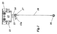
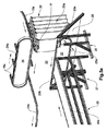
図1および図2の移送装置10’は、搬送方向(図1の矢印)に延び、図1の例では水平方向に延びる走行レール15を備え、図示の例における前記走行レールは、垂直中心面に対して対称的に繰り返し曲げられた金属片から作られており、また、この走行レールは、2つの相対する支持レールと、矩形の輪郭を有する中心底部に構成されたガイドレールとを備える。走行レール15に吊支されたキャリッジ11は、レールの方向に移動可能に案内される。キャリッジ11はU字形キャリッジ本体12(図4参照)を有し、U字形キャリッジ本体12は、両アームに一対の支持ローラ21a,21bをそれぞれ支持し、下部領域ではガイドローラ21cを支持し、このガイドローラによって、U字形キャリッジ本体12は横方向にかつ下方から走行レール15に係合する。
1 and 2 includes a traveling
横ローラ対21a,21b間には、外側に突出する駆動要素22a,22bがキャリッジ本体12に取り付けられ、前記駆動要素は、キャリッジを、必要に応じて、駆動装置、制動装置、切換装置などと係合した状態にすることができる。U字形キャリッジ本体12の下部ベースからは、レール方向と直角の方向に互いに離間された一対の固定要素14および/または14a,14b(図4)と、固定要素の進行方向後側に配置された一対の支持要素13とが垂直下方に突出している。
Driving
2本のロッド状の固定要素14および/または14a,14bは、下端部で、水平にかつレール方向に対して直角の方向にかつ対称的に延びる第1の横方向ロッド17に固定的に連結されている。関連のフック13aを有する支持要素13は第2の横方向ロッド16を受容し、第2の横方向ロッド16は、第1の横方向ロッド17と平行に配置され、いわば、フック13aに「引っ掛けられ(掛合され)」、再び取り外される(すなわち、掛合解除される)ことができる。
The two rod-shaped
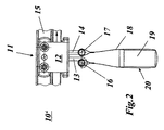
2本の横方向ロッド16,17はそれぞれ、所定の幅および長さを有する長方形の布地ウェブ18の端部に構成された、関連のポケット20における縫合された筒状部に収容される。掛合解除状態(図1)では、布地ウェブ18は、横方向ロッド17によって、自由状態の横方向ロッド16と共に垂直下方にキャリッジ11に吊支され、したがって平面状ウェブの形状を呈する。横方向ロッド16がフック形支持要素13に吊支されている掛合状態(図2)では、布地ウェブ18は、側面が開放しているキャリングループもしくは移送ループおよび/またはポケット20を形成して、その中に移送されるべき被移送物19、例えば小箱や小包みなどを入れることができる。
The two
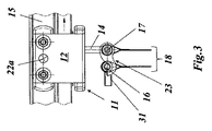
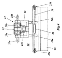
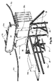
図3および図4の例示的な実施形態は、移送装置10を示すものであり、キャリッジ本体12に取り付けられるフック形支持要素13が設けられておらず、代わりに、フック23および/またはフック23a,23bが横方向ロッド16を受けるために横方向ロッド17の外端に取り付けられているという点で、図1および図2の例示的な実施形態(移送装置10’)とは異なる。
The exemplary embodiment of FIGS. 3 and 4 shows the
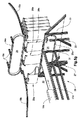
以下、移送装置のこの例示的な実施形態に基づき、荷積み装置の例示的な実施形態によって以下に本発明を詳細に説明する。この場合の図5a〜図5gは、この荷積み装置を用いて荷積みプロセスを概略的にかつ非常に単純化した形で再現するアニメーションにおける様々な経時的画像を示すものである。 In the following, the present invention will be described in detail below by means of an exemplary embodiment of a loading device based on this exemplary embodiment of the transfer device. FIGS. 5a to 5g in this case show various time-lapse images in an animation that reproduces the loading process in a schematic and very simplified manner using this loading device.
図5aによれば、例示的な荷積み装置30は、ポケット20をその荷積み装置30に送る第1の走行レール15aの終点部分と、荷積み済みのポケットを別のところに移動させる第2の走行レール15bの始点部分との間に配置されている。この例では、2つの走行レール15a,15bは、進行方向と直角の方向に互いに対して横方向にオフセットされている。しかし、他の構成、例えば、走行レールの垂直方向でのオフセットも考えられる。
According to FIG. 5a, an
荷積み装置30は、走行レール15a,15b間の横方向オフセットを橋渡しする2つの移送装置24,25を有し、移送装置24,25はそれぞれ、無限循環移送手段(鎖やベルトなど)24aおよび/または25aを備え、図5aに示されている矢印の方向に互いに同期して移動する。移送装置24,25の駆動部および案内要素は、単純化の目的で図示していない。
The
上側の移送装置24の循環移送手段24aは複数の走行レールセクション15cを支持しており、走行レールセクション15cは互いに等間隔に配置され、それぞれ、走行レール15a,15bと同じ輪郭を有し、移送手段24の特定の位置で走行レール15a,15bと係合した状態にすることができ、したがって、キャリッジ11を有するポケット20は、走行レール15aから隣接する走行レール部15cまでの移行部なしに、および/または走行レール部15cから隣接する走行レール15bまでの移行部なしに移動することができる。したがって、移送装置24は、走行レール15aからキャリッジ11付きのポケット20を受け取り、次いで、それを走行方向と直角の方向に走行レール15bまで移動させ、そこでそのポケット20を再び送り出すことができる。
The circulating transfer means 24a of the
これと同時に、下側の移送装置25の循環移送手段25aは、ポケット20aの横方向ロッド16の外側に固定されたグリップ要素31を受けるようになっており、ポケット20aが横方向ロッド16の掛合を解除することで開放され、そして布地ウェブ18の掛合解除された端部がグリップ要素31と共に移送装置25上にまで下降されたときに、グリップ要素31は掛合解除されることが可能である(図5c)。開放されたポケット20および/または20aは、2つの移送装置24,25によって、荷積み装置30を通して走行レール15a,15bと直角の方向に同時に移送され、それと同時に荷積みがなされ(図5d)、再び閉鎖される(図5f)。開放されたポケットを安定した状態に保つために、斜めに配置された支持面29が設けられており、支持面29の上縁部は下側の移送装置25の上部走路に隣接し、布地ウェブ18は、掛合解除された横方向ロッド16から布地ウェブ18のループまでの部分で支持面29に当接される。
At the same time, the circulating transfer means 25a of the
ポケット20および/または20aを開放し(掛合解除し)閉鎖する(掛合する)場合、自動的に作動される掛合解除装置28および掛合装置27は、荷積み装置の始点部分および終点部分に配置される。掛合解除装置28は垂直方向に可動な作動ロッド28aを有し、作動ロッド28aの自由端には横方向に配置された係合要素28bが固定されており、ポケット20および/または20aの前側の横方向ロッド16を掛合解除するために、作動ロッド28aは、係合要素28bによってポケット20および/または20aのグリップ要素31と係合した状態にすることができる(図5b)。これが可能になるように、作動ロッド28aは、作動ロッド28aの駆動機構によって、支持面29の凹所29aを通って開放されるべきポケットまでレール方向に進められ得る(図5b)。それに対応して、作動ロッド27aおよび係合要素27bを備えた掛合装置27は、支持面29の凹所29bを通って閉鎖されるべきポケット上にまでレール方向に進められ得る。(図5f)。
When the
荷積み装置30の掛合解除装置28と掛合装置27との間には供給装置26が配置され、ポケット内に荷積みされるべき被移送物、例えば小箱19a(図5c)が、供給装置26によって開放ポケットの中に供給され方向転換され得る。図5の例示的な実施形態では、供給装置26には、支持面29の上縁部で終端する移送ベルト26aが設けられている。
A
図5a〜図5gは、3つのポケット20a,20b,20cが例示した荷積み装置30を用いて同時に処理され得ることを示している。
FIGS. 5 a-5 g show that three
図5aでは、荷積みされるべき第1のポケット20aは、上側の移送装置の走行レール部15上の第1のポケット20aのキャリッジによりまだ開放されていない。
In FIG. 5a, the
図5bでは、作動部材28a,28bを備えた掛合解除装置28は、凹所29aを通って走行レール15aの方向に前進させられ、ポケット20aのグリップ要素31の下で作動部材を垂直方向に伸ばすことにより、前側の横方向ロッド16を掛合解除し、したがってポケットを開放する。
In FIG. 5b, the
図5cでは、作動部材28a,28bを引っ込めることにより、掛合解除装置28は、グリップ要素31を有するポケットおよび/または布地ウェブ18の掛合が解除された端部を下側の移送装置25上に置いたところであり、両移送装置24,25は、開放されたポケットを供給装置26に対して横方向にさらなる距離だけ既に移送したところである。
In FIG. 5 c, by retracting the
図5dでは、第1のポケット20aは供給装置の上流側に配置され、小箱19aが積み込まれている。それと同時に、荷積み装置30の始点部分で、第2のポケット20bが前方に滑り込み、掛合解除装置28によって既に開示された態様で開放される。
In FIG. 5d, the
図5eでは、荷積みされた開放された第1のポケット20aは、閉鎖するために掛合装置27までさらに移送され、それと同時に、第2のポケット20bは、別の小箱19bを既に進めている供給装置26の領域に入る。
In FIG. 5e, the loaded open
図5fでは、第1のポケット20aは掛合装置27を用いて閉鎖され、第2のポケット20bは小箱19bが積み込まれ、第3のポケット20cは掛合解除装置28によって開放されている。
In FIG. 5 f, the
最後に、図5gでは、荷積みされ閉鎖された第1のポケット20aは、走行レール15bを通って別のところへ移動させられ、第2のポケット20bは荷積みされ、第3のポケット20cは開放され、横方向移送の準備状態となる。
Finally, in FIG. 5g, the loaded and closed
Claims (18)
前記移送装置(10)が1つまたは複数のキャリッジ(11)を備え、前記キャリッジ(11)が、走行レール(15,15a,15b)に、前記走行レールの方向に移動可能に取り付けられ、垂下したポケット(20,20a〜20c)がそれぞれ、被移送物(19,19a〜19c)を受容することができるよう前記キャリッジ(11)に配置され、前記ポケット(20,20a〜20c)が少なくとも1枚の可撓性の布地ウェブ(18)によって形成され、前記布地ウェブが開放状態では平面状となり、前記布地ウェブが両端で前記キャリッジ(11)に固定されて垂下したキャリングループおよび/または移送ループを形成し、前記キャリッジ(11)に対する前記布地ウェブ(18)の固定が、前記布地ウェブ(18)の少なくとも一端(16)にて解除可能に行われる、方法において、
(a)前記ポケット(20,20a〜20c)を閉鎖状態で進行させるステップと、
(b)前記布地ウェブ(18)の前記少なくとも一端(16)と前記キャリッジ(11)との固定を解除することによって前記ポケット(20,20a〜20c)を開放するステップと、
(c)前記開放されたポケットの中に被移送物(19,19a〜19c)を荷積みするステップと、
(d)前記布地ウェブ(18)の前記少なくとも一端(16)を前記キャリッジ(11)に固定することによって前記ポケット(20,20a〜20c)を閉鎖するステップと、
(e)荷積みされ閉鎖された前記ポケット(20,20a〜20c)を別のところに移動させるステップと
を含むことを特徴とする、方法。 A method of loading into pockets (20, 20a-20c) of a transfer device (10) in the form of a suspension conveyor,
The transfer device (10) includes one or a plurality of carriages (11), and the carriage (11) is attached to the traveling rails (15, 15a, 15b) so as to be movable in the direction of the traveling rails. The pockets (20, 20a to 20c) are respectively arranged on the carriage (11) so as to receive the transferred objects (19, 19a to 19c), and the pockets (20, 20a to 20c) are at least 1 Carrying group and / or transfer loop formed by a single piece of flexible fabric web (18), said fabric web being planar when open, said fabric web being suspended at both ends fixed to said carriage (11) And the fabric web (18) is secured to the carriage (11) at least by the fabric web (18). Releasably carried out at one end (16), in the method,
(A) advancing the pockets (20, 20a to 20c) in a closed state;
(B) opening the pockets (20, 20a-20c) by releasing the fixation between the at least one end (16) of the fabric web (18) and the carriage (11);
(C) loading the transferred object (19, 19a to 19c) in the opened pocket;
(D) closing the pockets (20, 20a-20c) by securing the at least one end (16) of the fabric web (18) to the carriage (11);
(E) moving the loaded and closed pockets (20, 20a-20c) to another location.
開放された前記ポケット(20,20a〜20c)に荷積みするための第2の装置(26,26a)と、
荷積みされた前記ポケット(20,20a〜20c)を閉鎖するための第3の装置(27,27a,27b)と
を備える、荷積み装置(30)の形態をとる、請求項1〜8のいずれか一項に記載の方法を実行するための装置であって、
前記第1の装置、前記第2の装置および前記第3の装置が、前記ポケット(20,20a〜20c)の移送方向に互いに前後にかつ互いに離れて配置されている、装置。 A first device (28, 28a, 28b) for opening the pocket (20, 20a-20c);
A second device (26, 26a) for loading into the opened pockets (20, 20a-20c);
9. In the form of a loading device (30) comprising a third device (27, 27a, 27b) for closing the loaded pocket (20, 20a-20c). An apparatus for performing the method according to any one of
The device, wherein the first device, the second device and the third device are arranged one after the other and away from each other in the transfer direction of the pockets (20, 20a-20c).
前記荷積み装置(30)が、前記ポケット(20,20a〜20c)を前記第1の走行レール(15a)の前記終点部分から前記第1の装置(28a,28b)、前記第2の装置(26,26a)および前記第3の装置(27,27a,27b)を通って前記第2の走行レール(15b)の前記始点部分まで移送するために構成された移送装置(24,24a,25,25a)を備えることを特徴とする、請求項9に記載の装置。 The loading device (30) includes an end point portion of a first traveling rail (15a) in which the pockets (20, 20a to 20c) to be loaded can travel, and the loaded pockets ( 20, 20 a to 20 c) can be moved to another place between the starting point portion of the second traveling rail (15 b) separated from the end point portion of the first traveling rail (15 a). Arranged,
The loading device (30) moves the pocket (20, 20a to 20c) from the end point portion of the first traveling rail (15a) to the first device (28a, 28b), the second device ( 26, 26a) and transfer devices (24, 24a, 25, 25) configured to transfer through the third device (27, 27a, 27b) to the starting point portion of the second travel rail (15b). 25. The device according to claim 9, comprising 25a).
Applications Claiming Priority (5)
| Application Number | Priority Date | Filing Date | Title |
|---|---|---|---|
| CH00089/15A CH710650A1 (en) | 2015-01-26 | 2015-01-26 | Transport device, in particular in the form of a suspension conveyor. |
| CH00089/15 | 2015-01-26 | ||
| CH00572/15 | 2015-04-27 | ||
| CH00572/15A CH710663A1 (en) | 2015-01-26 | 2015-04-27 | A method of filling the pockets of a transport device in the form of an overhead conveyor, and device for carrying out the method. |
| PCT/EP2016/050160 WO2016120031A1 (en) | 2015-01-26 | 2016-01-07 | Method for filling the pockets of a transport device in the form of a suspension conveyor and device for carrying out said method |
Publications (2)
| Publication Number | Publication Date |
|---|---|
| JP2018503573A true JP2018503573A (en) | 2018-02-08 |
| JP2018503573A5 JP2018503573A5 (en) | 2018-11-15 |
Family
ID=55129832
Family Applications (1)
| Application Number | Title | Priority Date | Filing Date |
|---|---|---|---|
| JP2017535027A Pending JP2018503573A (en) | 2015-01-26 | 2016-01-07 | Method for loading into a pocket of a transfer device in the form of a suspension conveyor and device for carrying out the method |
Country Status (15)
| Country | Link |
|---|---|
| US (4) | US10005616B2 (en) |
| EP (5) | EP3647238A1 (en) |
| JP (1) | JP2018503573A (en) |
| KR (1) | KR20170106972A (en) |
| CN (1) | CN107406198B (en) |
| AT (1) | AT17337U1 (en) |
| AU (1) | AU2016212416B2 (en) |
| BR (1) | BR112017013972A2 (en) |
| CA (1) | CA2973513A1 (en) |
| CH (3) | CH710650A1 (en) |
| CO (1) | CO2017007285A2 (en) |
| DE (1) | DE202016008366U1 (en) |
| EA (1) | EA035700B1 (en) |
| MX (1) | MX2017009577A (en) |
| WO (3) | WO2016120030A1 (en) |
Families Citing this family (27)
| Publication number | Priority date | Publication date | Assignee | Title |
|---|---|---|---|---|
| CH710650A1 (en) | 2015-01-26 | 2016-07-29 | Ferag Ag | Transport device, in particular in the form of a suspension conveyor. |
| WO2017088076A1 (en) * | 2015-11-25 | 2017-06-01 | Ferag Ag | Transport bag and method for filling and emptying a transport bag of this type |
| CH712895A1 (en) | 2016-09-09 | 2018-03-15 | Ferag Ag | Method for opening a transport bag hanging on a carriage and pocket opening device for carrying out the method. |
| CH713398A1 (en) | 2017-01-31 | 2018-07-31 | Ferag Ag | Device for emptying hanging conveyed transport bags. |
| CH713759A1 (en) * | 2017-05-05 | 2018-11-15 | Ferag Ag | Device for loading transport bags. |
| CH713399A1 (en) | 2017-01-31 | 2018-07-31 | Ferag Ag | Feed unit for hanging transport of transport elements in two positions. |
| EP3532413B1 (en) | 2016-10-27 | 2022-10-05 | Ferag AG | Method and device for opening a transport bag |
| DE202017100206U1 (en) * | 2017-01-16 | 2018-04-17 | Tgw Mechanics Gmbh | Fördergutbehälter with ejection device and associated overhead conveyor |
| CH713387A1 (en) * | 2017-01-26 | 2018-07-31 | Ferag Ag | Feeding device for the continuous loading of receiving units with goods to be transported. |
| US11878876B2 (en) | 2017-01-31 | 2024-01-23 | Ferag Ag | Device for emptying transport bags conveyed in a suspended manner |
| CH713551A1 (en) | 2017-03-07 | 2018-09-14 | Ferag Ag | Method for picking goods and picking plant for carrying out the method. |
| WO2018202512A2 (en) * | 2017-05-05 | 2018-11-08 | Ferag Ag | Device for loading transport bags |
| JP6907836B2 (en) * | 2017-09-07 | 2021-07-21 | 株式会社ダイフク | Transport equipment |
| JP6922567B2 (en) * | 2017-09-07 | 2021-08-18 | 株式会社ダイフク | Hanging storage body |
| CH714814A1 (en) * | 2018-03-20 | 2019-09-30 | Ferag Ag | Conveying device for clocking in transport units. |
| AT520517B1 (en) * | 2018-04-13 | 2019-05-15 | Tgw Mechanics Gmbh | Unloading station and method for unloading a conveyed goods container loaded with a conveyed item |
| DE102018128417A1 (en) | 2018-06-07 | 2019-12-12 | Emhs Gmbh | Method and device for autonomous or semi-autonomous transport and sorting of general cargo |
| DE102018212591A1 (en) | 2018-07-27 | 2020-01-30 | Vanderlande Industries B.V. | Loading station for a pocket conveyor |
| CN109398850B (en) * | 2018-10-18 | 2020-11-24 | 无为华塑矿业有限公司 | Art ton bag packing plant |
| AT521961B1 (en) * | 2019-01-25 | 2020-07-15 | Tgw Mechanics Gmbh | Conveyed goods container for a suspended conveyor and unloading station for unloading the same |
| CH716519A1 (en) | 2019-08-22 | 2021-02-26 | Ferag Ag | Device and method for transferring goods units in conveyor units and / or from conveyor units of an overhead conveyor system. |
| EP4074629B1 (en) | 2021-04-16 | 2023-10-11 | BEUMER Group GmbH & Co. KG | Overhead conveyor with unloading station |
| DE102021002833A1 (en) * | 2021-06-02 | 2021-08-12 | Paul Janzen | Transport bag for the hanging transport of conveyed goods as well as loading station and conveyor system for these transport bags |
| WO2023095049A1 (en) | 2021-11-29 | 2023-06-01 | Ferag Ag | Device for managing the loading of transport units of a conveyor system |
| CN114987995B (en) * | 2022-04-27 | 2023-12-26 | 宁波郎泰机械有限公司 | Transfer equipment convenient for loading and unloading and used for manufacturing automobile hubs |
| EP4286303A1 (en) | 2022-05-31 | 2023-12-06 | Ferag Ag | Device and method for introducing goods units into a transport container |
| EP4342822A1 (en) * | 2022-09-20 | 2024-03-27 | BEUMER Group GmbH & Co. KG | Pocket loading station for loading and/or unloading carrying pockets of a suspension conveyor and a corresponding method |
Family Cites Families (85)
| Publication number | Priority date | Publication date | Assignee | Title |
|---|---|---|---|---|
| US140163A (en) | 1873-06-24 | Improvement in medical compounds for diphtheria | ||
| CH8915A (en) | 1894-09-07 | 1895-02-15 | Emil Mueller | Device for eliminating interference in telephone lines |
| GB733714A (en) * | 1953-03-12 | 1955-07-20 | Prep Ind Combustibles | Improvements in or relating to endless conveyors |
| GB1047344A (en) | 1963-02-27 | |||
| US3338179A (en) * | 1964-10-12 | 1967-08-29 | Richard W Klemm | Lift mechanism for rail conveyors |
| DE1233777B (en) | 1965-06-01 | 1967-02-02 | Werner Busch | Suspension conveyor belt |
| US3533499A (en) | 1968-05-20 | 1970-10-13 | Hewitt Robins Inc | Friction drive assembly |
| CH507828A (en) * | 1969-05-09 | 1971-05-31 | Von Roll Ag | Device for the pivotable mounting of a load container on a chassis of overhead conveyors |
| DE2221318A1 (en) * | 1972-04-29 | 1973-11-15 | Jung Gmbh Lokomotivfab Arn | CONTAINER FOR TRANSPORTING BULK GOODS |
| DE2233777C3 (en) | 1972-07-08 | 1975-03-13 | Autoelektronik Ag, Chur, Graubuenden (Schweiz) | Fuel and air metering device for a mixture-compressing spark-ignited internal combustion engine |
| US3782529A (en) * | 1972-07-12 | 1974-01-01 | Bucciconi Eng Co | Magnetic rail conveyor |
| US3807314A (en) * | 1973-03-30 | 1974-04-30 | Us Army | Magnetic trolley conveyor system |
| JPS5273485A (en) * | 1975-12-11 | 1977-06-20 | Murata Mach Ltd | Apparatus for forwarding, collecting and delivering trolley for transp orting goods |
| US4051946A (en) * | 1976-03-12 | 1977-10-04 | Bucciconi Engineering Co., Inc. | Magnetic conveyor |
| US4079840A (en) * | 1976-10-06 | 1978-03-21 | Usner Daniel C | Clothes hanger bridle for a garment trolley bar |
| US4104156A (en) * | 1977-06-13 | 1978-08-01 | Fletcher John K | Detachable sling letdown apparatus for lumber sorter |
| US4297959A (en) * | 1978-01-25 | 1981-11-03 | C. L. Frost & Son, Inc. | Method for making chain bracket with strengthened chain supports |
| DE8133433U1 (en) | 1981-11-12 | 1982-03-18 | Danneberg, Joerg, 8500 Nuernberg | Device for transporting a laundry bag by means of a hanging roller conveyor |
| GB2164628B (en) * | 1984-09-17 | 1987-12-02 | Gerber Garment Technology Inc | Conveyor hanger assembly |
| SE448083B (en) * | 1985-05-29 | 1987-01-19 | Per Erik Wahren | TRANSPORT COURSE WITH PALETTS FOR TRANSPORTING LINER LOADS |
| US4878577A (en) * | 1986-11-04 | 1989-11-07 | Investronica, S.A. | Peg for overhead trouser conveyor |
| DE3819102C1 (en) * | 1988-06-04 | 1989-10-12 | Jennewein, Manfred A., 6082 Moerfelden-Walldorf, De | |
| US4925015A (en) * | 1988-07-07 | 1990-05-15 | Gerber Garment Technology, Inc. | Variable position carrier body |
| US4848538A (en) * | 1988-07-07 | 1989-07-18 | Gerber Garment Technology, Inc. | Carrier and variable position carrier body |
| DE3840521A1 (en) | 1988-12-01 | 1990-06-07 | Heinemann C A Gmbh | Automatically operated overhead conveying system for piece goods |
| NL8803144A (en) | 1988-12-22 | 1990-07-16 | Johannes Gerhardus Christianus | SORTING DEVICE EQUIPPED WITH TWO-SIDED OPERATING PROTECTION CUSHIONS. |
| US4922829A (en) * | 1989-08-29 | 1990-05-08 | Gerber Garment Technology, Inc. | Variable height workstation and system |
| DE9003123U1 (en) * | 1990-03-16 | 1991-07-18 | Veit Transpo Gmbh, 8910 Landsberg, De | |
| DE4042375C2 (en) * | 1990-05-09 | 1995-10-19 | Kannegiesser H Gmbh Co | Clamp holder for fixing a piece of laundry to be transported to a mangle or the like |
| JP3060257B2 (en) | 1991-11-13 | 2000-07-10 | セントラルコンベヤー株式会社 | Opening / closing device for bag bottom in bag conveyor, locking mechanism used for the device, and device for preventing swinging of bag |
| IT1252404B (en) | 1991-11-14 | 1995-06-12 | Barilla Flli G & R | LASAGNE CONVEYOR AND SIMILAR EDIBLE PASTA FORMATS THROUGH A DRYER |
| CN2151116Y (en) * | 1992-09-12 | 1993-12-29 | 王翰声 | Carrier of hanging conveyer |
| US5346052A (en) * | 1993-04-23 | 1994-09-13 | Fox Harvey Z | Feed bucket for programmed delivery system |
| US5566623A (en) * | 1995-09-05 | 1996-10-22 | Saginaw Products, Inc. | Wheel and bearing system for a load transporting overhead trolley assembly |
| DE19614905C2 (en) * | 1996-04-16 | 1998-03-19 | Duerkopp Adler Ag | Conveyor bag for a overhead conveyor |
| US5697508A (en) * | 1996-07-24 | 1997-12-16 | A. Rifkin & Co. | Trolley and bag assembly for transporting hanger-hung garments |
| DE29709547U1 (en) * | 1997-06-02 | 1997-08-14 | Psb Foerderanlagen | Overhead conveyor system for goods hanging on hangers |
| EP1042206B1 (en) * | 1997-12-23 | 2002-05-22 | Ferag AG | Device for receiving and/or conveying flat products |
| RU2200694C2 (en) * | 1997-12-23 | 2003-03-20 | Фераг Аг | Conveyor device |
| JP2001527010A (en) * | 1997-12-23 | 2001-12-25 | フェラーク アーゲー | Conveyor system |
| DK1042202T3 (en) * | 1997-12-23 | 2003-03-31 | Ferag Ag | Rail-transportable means and guide rail for transporting the means of transport |
| DE50103205D1 (en) * | 2000-12-18 | 2004-09-16 | Ferag Ag | Rail-guided conveyor and conveyor system |
| CN2511116Y (en) | 2001-12-18 | 2002-09-18 | 王春友 | Straw compression packer |
| US6942111B2 (en) * | 2002-11-13 | 2005-09-13 | Rodney Harrell | Trolley device and method for transporting articles along a rail system |
| EP1420106A1 (en) * | 2002-11-15 | 2004-05-19 | Jensen AG Burgdorf | Clothes support and loading station |
| EP1420105A1 (en) | 2002-11-15 | 2004-05-19 | Jensen AG Burgdorf | Laundry carrier and loading station |
| DE10309127A1 (en) * | 2003-02-28 | 2004-09-09 | Conteyor Multibag Systems N.V. | Device for transporting and / or storing piece goods |
| DE102004018569B4 (en) * | 2004-04-16 | 2016-06-09 | Psb Intralogistics Gmbh | Collecting device for picking up objects during sorting collecting the objects and conveying device for transporting collecting bags |
| US20120003727A1 (en) * | 2006-03-10 | 2012-01-05 | Javanbakhsh Esfandiari | Immunoassay Device for Detecting Antibodies and Antigens |
| DE102008026720A1 (en) * | 2008-06-04 | 2009-12-10 | Dürkopp Adler AG | Transportation Bag and Carrying Facility for a Transportation Bag |
| DE102008037188A1 (en) * | 2008-08-11 | 2010-02-18 | Krones Ag | Apparatus and method for forming piece goods compositions |
| DE102008061685A1 (en) * | 2008-12-11 | 2010-06-17 | Dürkopp Adler AG | Loading station for transport bags transported in a suspended conveyor system |
| DE102009026720A1 (en) | 2009-06-04 | 2010-12-09 | Robert Bosch Gmbh | High pressure fuel pump for supplying fuel in fuel injection system of internal combustion engine, has drive gears lubricated with lubricant in drive gear chamber, and closed lubricant volume provided in drive gear chamber |
| DE102010033905A1 (en) | 2010-08-10 | 2012-02-16 | Dürkopp Fördertechnik GmbH | Conveying system with carrying bags for conveyed goods |
| DE102010053590B4 (en) | 2010-12-06 | 2019-03-07 | Dürkopp Fördertechnik GmbH | Carrying bag for conveyed goods and conveyor for a carrying bag |
| US8490774B2 (en) * | 2011-02-24 | 2013-07-23 | Dürkopp Fördertechnik GmbH | Loading station for transport bags transported in an overhead conveyor system |
| DE102011015138B4 (en) | 2011-03-17 | 2014-05-08 | SSI Schäfer PEEM GmbH | Overhead conveyor transport bag and method for automated unloading of the transport bag |
| DE102011101987A1 (en) | 2011-05-17 | 2012-11-22 | SSI Schäfer PEEM GmbH | Conveyor and transport bag for a conveyor system and method for transporting a conveyed material |
| DE102011080441B4 (en) * | 2011-08-04 | 2023-01-12 | Krones Aktiengesellschaft | Storage device for a bottling plant and beverage bottling plant with such a storage device |
| CN202320939U (en) * | 2011-11-25 | 2012-07-11 | 陈世敏 | Hanging type automatic bag opening, emptying and unloading device for mail bag sorting |
| ES2464018T3 (en) * | 2012-01-24 | 2014-05-29 | Dürkopp Fördertechnik GmbH | Transport installation with carrier bags for materials to be transported |
| US9016464B2 (en) * | 2012-04-04 | 2015-04-28 | Sst Systems, Inc. | Tilting multiplier |
| DE102012209978A1 (en) * | 2012-06-14 | 2013-12-19 | Robert Bosch Gmbh | Device for transporting objects, in particular packaging |
| DE102012212518B4 (en) * | 2012-07-17 | 2023-12-07 | Rsl Logistik Gmbh & Co. Kg | Container for goods to be conveyed, overhead conveyor device and method for transporting |
| DE102012018925B4 (en) * | 2012-09-18 | 2020-06-18 | Ssi Schäfer Automation Gmbh | Bag for overhead conveyor, loading station, unloading station and pocket overhead conveyor system |
| DE102012108757A1 (en) | 2012-09-18 | 2014-03-20 | Psb Intralogistics Gmbh | Carrying bag for a hanging conveyor for hanging objects, closing mechanism for closing a bag and hanging conveyor |
| CN203048067U (en) * | 2013-01-21 | 2013-07-10 | 上海航星机械(集团)有限公司 | Bag-hanging-type linen conveying system |
| DE102013205170A1 (en) | 2013-03-22 | 2014-09-25 | Dürkopp Fördertechnik GmbH | Loading station for transport bags for the hanging transport of goods |
| DE102013205172B4 (en) * | 2013-03-22 | 2018-03-22 | Dürkopp Fördertechnik GmbH | Transport bag for hanging transport of goods, loading station and conveyor system |
| DE102013005251A1 (en) | 2013-03-27 | 2014-10-02 | Herbert Kannegiesser Gmbh | Method and device for transporting and / or measuring laundry items |
| JP5915585B2 (en) * | 2013-04-11 | 2016-05-11 | トヨタ自動車株式会社 | Transport device |
| DE102014203299A1 (en) * | 2014-02-24 | 2015-08-27 | Rsl Logistik Gmbh & Co. Kg | Hanging bag with removable element |
| DE102014203298A1 (en) | 2014-02-24 | 2015-08-27 | Rsl Logistik Gmbh & Co. Kg | Hanging conveyor with charging station |
| CH709392A1 (en) * | 2014-03-20 | 2015-09-30 | Ferag Ag | Eintaktvorrichtung for gravity conveyors. |
| US9932170B2 (en) * | 2014-04-25 | 2018-04-03 | Glen Munholland | Cargo carousel system for shipping containers and method for using same |
| DE202014010433U1 (en) * | 2014-07-02 | 2015-07-27 | Meri Environmental Solutions Gmbh | Conveying system for conveying conveyed goods |
| CH710024A1 (en) | 2014-08-27 | 2016-02-29 | Ferag Ag | Running rail and method for producing such a rail. |
| CH710022A1 (en) | 2014-08-27 | 2016-02-29 | Ferag Ag | Carriage for a conveyor system, in particular for a gravity conveyor, conveyor system and method for operating a conveyor system. |
| DE102014224872A1 (en) | 2014-12-04 | 2016-06-09 | Vanderlande Industries B.V. | Transport bag for transporting goods in a hanging goods conveyor |
| CH710650A1 (en) | 2015-01-26 | 2016-07-29 | Ferag Ag | Transport device, in particular in the form of a suspension conveyor. |
| CH711565A1 (en) * | 2015-09-24 | 2017-03-31 | Ferag Ag | Transport bag for the transport and / or storage of objects and transport device with such a transport bag. |
| US9558472B1 (en) * | 2015-12-11 | 2017-01-31 | Amazon Technologies, Inc. | Inventory facility |
| EP3231741A1 (en) * | 2016-04-15 | 2017-10-18 | Dematic Logistics GmbH | Transport bag, conveyor assembly and a method of opening and closing a transport bag |
| CH712895A1 (en) | 2016-09-09 | 2018-03-15 | Ferag Ag | Method for opening a transport bag hanging on a carriage and pocket opening device for carrying out the method. |
| EP3301043B1 (en) * | 2016-09-29 | 2020-01-29 | Dürkopp Fördertechnik GmbH | Transport bag for overhead conveyor system |
-
2015
- 2015-01-26 CH CH00089/15A patent/CH710650A1/en not_active Application Discontinuation
- 2015-04-27 CH CH00573/15A patent/CH710664A1/en unknown
- 2015-04-27 CH CH00572/15A patent/CH710663A1/en not_active Application Discontinuation
-
2016
- 2016-01-07 US US15/542,880 patent/US10005616B2/en active Active
- 2016-01-07 KR KR1020177020807A patent/KR20170106972A/en unknown
- 2016-01-07 US US15/542,893 patent/US10301114B2/en active Active
- 2016-01-07 WO PCT/EP2016/050158 patent/WO2016120030A1/en active Application Filing
- 2016-01-07 EP EP19214957.3A patent/EP3647238A1/en not_active Withdrawn
- 2016-01-07 WO PCT/EP2016/050161 patent/WO2016120032A1/en active Application Filing
- 2016-01-07 CA CA2973513A patent/CA2973513A1/en not_active Abandoned
- 2016-01-07 JP JP2017535027A patent/JP2018503573A/en active Pending
- 2016-01-07 EA EA201791586A patent/EA035700B1/en not_active IP Right Cessation
- 2016-01-07 DE DE202016008366.0U patent/DE202016008366U1/en active Active
- 2016-01-07 WO PCT/EP2016/050160 patent/WO2016120031A1/en active Application Filing
- 2016-01-07 BR BR112017013972-3A patent/BR112017013972A2/en active Search and Examination
- 2016-01-07 MX MX2017009577A patent/MX2017009577A/en unknown
- 2016-01-07 CN CN201680007139.6A patent/CN107406198B/en active Active
- 2016-01-07 EP EP16700538.8A patent/EP3250486B1/en active Active
- 2016-01-07 EP EP17187594.1A patent/EP3305689A1/en not_active Ceased
- 2016-01-07 AT ATGM184/2017U patent/AT17337U1/en not_active IP Right Cessation
- 2016-01-07 EP EP16700396.1A patent/EP3250485B1/en active Active
- 2016-01-07 EP EP16700395.3A patent/EP3250484B1/en active Active
- 2016-01-07 AU AU2016212416A patent/AU2016212416B2/en not_active Ceased
- 2016-01-07 US US15/542,887 patent/US10040641B2/en active Active
-
2017
- 2017-07-21 CO CONC2017/0007285A patent/CO2017007285A2/en unknown
-
2018
- 2018-06-25 US US16/017,473 patent/US10336548B2/en active Active
Also Published As
Similar Documents
| Publication | Publication Date | Title |
|---|---|---|
| JP2018503573A (en) | Method for loading into a pocket of a transfer device in the form of a suspension conveyor and device for carrying out the method | |
| US10494196B2 (en) | Method for opening a transport pocket suspended on a carriage as well as a pocket opening device for performing the method | |
| NL2001268C2 (en) | ARTICLE TRANSPORT. | |
| KR20170057848A (en) | Container transport facility | |
| WO2020008915A1 (en) | Fabric transport device | |
| SU1734574A3 (en) | Overhead belt conveyer | |
| JP2004014749A (en) | Automatic guided vehicle system | |
| JP5392625B2 (en) | Loading guide mounting device and mounting method | |
| JP2001063812A (en) | Trolley hanger and belt conveyor | |
| JP5100365B2 (en) | Transit hanger | |
| JP2010168171A (en) | Friction drive type workpiece conveying system | |
| JP4862305B2 (en) | Component supply apparatus, component supply system, and component supply method | |
| JP2004014751A (en) | Traveling track | |
| JP2004010247A (en) | Traveling path for ceiling traveling vehicle | |
| JP2000118289A (en) | Method for transporting clothes by transport truck while still hanging clothes on hanger | |
| JPH0669791B2 (en) | Carrier | |
| US20190315279A1 (en) | Narrow Door Vehicle Sling Bag Track System | |
| JP2003040413A (en) | Hanging conveyor | |
| JP2004014750A (en) | Automatic guided vehicle | |
| JPH1149341A (en) | Loading device for hanger goods sorting trolley | |
| JP2011201672A (en) | Article casting method | |
| JP2004010248A (en) | Traveling path | |
| JP2004168462A (en) | Conveyance facility | |
| JP2004136724A (en) | Trolley conveyer | |
| JPH1149340A (en) | Unloading device for hanger item carrier trolley |
Legal Events
| Date | Code | Title | Description |
|---|---|---|---|
| A521 | Request for written amendment filed |
Free format text: JAPANESE INTERMEDIATE CODE: A523 Effective date: 20181005 |
|
| A621 | Written request for application examination |
Free format text: JAPANESE INTERMEDIATE CODE: A621 Effective date: 20181031 |
|
| A977 | Report on retrieval |
Free format text: JAPANESE INTERMEDIATE CODE: A971007 Effective date: 20190807 |
|
| A131 | Notification of reasons for refusal |
Free format text: JAPANESE INTERMEDIATE CODE: A131 Effective date: 20190813 |
|
| RD04 | Notification of resignation of power of attorney |
Free format text: JAPANESE INTERMEDIATE CODE: A7424 Effective date: 20190913 |
|
| A02 | Decision of refusal |
Free format text: JAPANESE INTERMEDIATE CODE: A02 Effective date: 20200310 |