JP2018501839A - Imaging device and method for generating an image of a patient - Google Patents
Imaging device and method for generating an image of a patient Download PDFInfo
- Publication number
- JP2018501839A JP2018501839A JP2017527856A JP2017527856A JP2018501839A JP 2018501839 A JP2018501839 A JP 2018501839A JP 2017527856 A JP2017527856 A JP 2017527856A JP 2017527856 A JP2017527856 A JP 2017527856A JP 2018501839 A JP2018501839 A JP 2018501839A
- Authority
- JP
- Japan
- Prior art keywords
- image information
- patient
- image
- wavelength band
- imaging device
- Prior art date
- Legal status (The legal status is an assumption and is not a legal conclusion. Google has not performed a legal analysis and makes no representation as to the accuracy of the status listed.)
- Ceased
Links
Images

Classifications
-
- A—HUMAN NECESSITIES
- A61—MEDICAL OR VETERINARY SCIENCE; HYGIENE
- A61B—DIAGNOSIS; SURGERY; IDENTIFICATION
- A61B5/00—Measuring for diagnostic purposes; Identification of persons
- A61B5/0033—Features or image-related aspects of imaging apparatus classified in A61B5/00, e.g. for MRI, optical tomography or impedance tomography apparatus; arrangements of imaging apparatus in a room
- A61B5/0035—Features or image-related aspects of imaging apparatus classified in A61B5/00, e.g. for MRI, optical tomography or impedance tomography apparatus; arrangements of imaging apparatus in a room adapted for acquisition of images from more than one imaging mode, e.g. combining MRI and optical tomography
-
- A—HUMAN NECESSITIES
- A61—MEDICAL OR VETERINARY SCIENCE; HYGIENE
- A61B—DIAGNOSIS; SURGERY; IDENTIFICATION
- A61B5/00—Measuring for diagnostic purposes; Identification of persons
- A61B5/0059—Measuring for diagnostic purposes; Identification of persons using light, e.g. diagnosis by transillumination, diascopy, fluorescence
- A61B5/0077—Devices for viewing the surface of the body, e.g. camera, magnifying lens
-
- A—HUMAN NECESSITIES
- A61—MEDICAL OR VETERINARY SCIENCE; HYGIENE
- A61B—DIAGNOSIS; SURGERY; IDENTIFICATION
- A61B5/00—Measuring for diagnostic purposes; Identification of persons
- A61B5/103—Detecting, measuring or recording devices for testing the shape, pattern, colour, size or movement of the body or parts thereof, for diagnostic purposes
- A61B5/11—Measuring movement of the entire body or parts thereof, e.g. head or hand tremor, mobility of a limb
- A61B5/1126—Measuring movement of the entire body or parts thereof, e.g. head or hand tremor, mobility of a limb using a particular sensing technique
- A61B5/1128—Measuring movement of the entire body or parts thereof, e.g. head or hand tremor, mobility of a limb using a particular sensing technique using image analysis
-
- A—HUMAN NECESSITIES
- A61—MEDICAL OR VETERINARY SCIENCE; HYGIENE
- A61B—DIAGNOSIS; SURGERY; IDENTIFICATION
- A61B6/00—Apparatus for radiation diagnosis, e.g. combined with radiation therapy equipment
- A61B6/44—Constructional features of apparatus for radiation diagnosis
- A61B6/4429—Constructional features of apparatus for radiation diagnosis related to the mounting of source units and detector units
- A61B6/4435—Constructional features of apparatus for radiation diagnosis related to the mounting of source units and detector units the source unit and the detector unit being coupled by a rigid structure
- A61B6/4441—Constructional features of apparatus for radiation diagnosis related to the mounting of source units and detector units the source unit and the detector unit being coupled by a rigid structure the rigid structure being a C-arm or U-arm
-
- A—HUMAN NECESSITIES
- A61—MEDICAL OR VETERINARY SCIENCE; HYGIENE
- A61B—DIAGNOSIS; SURGERY; IDENTIFICATION
- A61B6/00—Apparatus for radiation diagnosis, e.g. combined with radiation therapy equipment
- A61B6/52—Devices using data or image processing specially adapted for radiation diagnosis
- A61B6/5211—Devices using data or image processing specially adapted for radiation diagnosis involving processing of medical diagnostic data
- A61B6/5229—Devices using data or image processing specially adapted for radiation diagnosis involving processing of medical diagnostic data combining image data of a patient, e.g. combining a functional image with an anatomical image
- A61B6/5235—Devices using data or image processing specially adapted for radiation diagnosis involving processing of medical diagnostic data combining image data of a patient, e.g. combining a functional image with an anatomical image combining images from the same or different ionising radiation imaging techniques, e.g. PET and CT
-
- A—HUMAN NECESSITIES
- A61—MEDICAL OR VETERINARY SCIENCE; HYGIENE
- A61B—DIAGNOSIS; SURGERY; IDENTIFICATION
- A61B6/00—Apparatus for radiation diagnosis, e.g. combined with radiation therapy equipment
- A61B6/52—Devices using data or image processing specially adapted for radiation diagnosis
- A61B6/5211—Devices using data or image processing specially adapted for radiation diagnosis involving processing of medical diagnostic data
- A61B6/5229—Devices using data or image processing specially adapted for radiation diagnosis involving processing of medical diagnostic data combining image data of a patient, e.g. combining a functional image with an anatomical image
- A61B6/5247—Devices using data or image processing specially adapted for radiation diagnosis involving processing of medical diagnostic data combining image data of a patient, e.g. combining a functional image with an anatomical image combining images from an ionising-radiation diagnostic technique and a non-ionising radiation diagnostic technique, e.g. X-ray and ultrasound
Abstract
本発明は、患者Pの画像を生成するイメージングデバイス100に関連する。当該イメージングデバイス100は、第1の波長帯域を使用して患者Pの第1の画像情報I1を提供し、第2の波長帯域を使用して患者Pの第2の画像情報I2を提供するカメラ装置10を含む。第1の波長帯域と第2の波長帯域のセットとは異なる。第1及び/又は第2の画像情報は、患者PのランドマークMのランドマーク情報を含む。ランドマーク情報は、可視スペクトル外の少なくとも1つの波長帯域によって導出される。更に、第1の画像情報I1及び第2の画像情報I2に基づいて、融合画像IEを生成し、融合画像IE内のランドマークMを検出するデータプロセッサ30が提供される。The present invention pertains to an imaging device 100 that generates an image of a patient P. The imaging device 100 provides a first image information I1 of the patient P using a first wavelength band, and a camera that provides a second image information I2 of the patient P using a second wavelength band. Device 10 is included. The set of the first wavelength band and the second wavelength band is different. The first and / or second image information includes landmark information of the landmark M of the patient P. The landmark information is derived by at least one wavelength band outside the visible spectrum. Furthermore, a data processor 30 is provided that generates a fused image IE based on the first image information I1 and the second image information I2 and detects a landmark M in the fused image IE.
Description
本発明は、ランドマークに関する情報を使用及び処理する患者の医用撮像を使用する画像処理に関連する。具体的には、本発明は、患者の画像を生成するイメージングデバイス及び方法に関する。 The present invention relates to image processing using medical imaging of a patient using and processing information about landmarks. Specifically, the present invention relates to imaging devices and methods for generating patient images.
画像誘導最小侵襲療法は、多数の介入療法及び最小侵襲療法において本格化している。このアプローチの主な前提は、患者にとって心的外傷が少ないこと、回復時間が速いこと、血液損失が少ないこと及び臨床転帰が改善されることである。最小侵襲の介入療法を行う間の画像誘導を改良するには、撮像及びナビゲーションが、ハードウェア及びソフトウェア的にシームレスに組み合わされ、統合される必要がある。 Image guided minimally invasive therapy is gaining momentum in a number of interventional and minimally invasive therapies. The main premise of this approach is that there is less trauma for the patient, faster recovery time, less blood loss and improved clinical outcome. To improve image guidance during minimally invasive interventional therapy, imaging and navigation need to be seamlessly combined and integrated in hardware and software.
患者を撮像及び追跡するイメージング装置及び方法を改良する必要がある。 There is a need for improved imaging devices and methods for imaging and tracking patients.
上記必要は、独立請求項の主題によって満たされる。更なる例示的な実施形態は、従属請求項及び以下の説明から明らかである。 This need is met by the subject matter of the independent claims. Further exemplary embodiments are evident from the dependent claims and the following description.
本発明の第1の態様は、患者の画像を生成するイメージングデバイスに関連する。当該イメージングデバイスは、第1の波長帯域を使用して患者の第1の画像情報を提供し、第2の波長帯域を使用して患者の第2の画像情報を提供するカメラ装置を含む。第1の波長帯域と第2の波長帯域とは異なる。第1及び/又は第2の画像情報は、血管又は患者の皮膚内の他の表面組織構造のランドマーク情報を自然マーカとして含む。更に、上記イメージングデバイスは、第1の画像情報及び第2の画像情報に基づいて、自然マーカを所定の閾値を上回るコントラストで示す融合画像を生成するデータプロセッサを含む。データプロセッサは更に、融合画像内の自然マーカを検出する。 A first aspect of the invention relates to an imaging device that generates an image of a patient. The imaging device includes a camera device that provides first image information of a patient using a first wavelength band and provides second image information of the patient using a second wavelength band. The first wavelength band and the second wavelength band are different. The first and / or second image information includes landmark information of blood vessels or other surface tissue structures in the patient's skin as natural markers. In addition, the imaging device includes a data processor that generates a fused image indicating the natural marker with a contrast exceeding a predetermined threshold based on the first image information and the second image information. The data processor further detects natural markers in the fused image.
一例では、データプロセッサは、融合画像内のランドマークを光学的に分解する。 In one example, the data processor optically resolves landmarks in the fused image.
本発明は、カメラ装置によって、自然の位置マーカをスペクトル分解することを有利に可能にする。このマーカは、例えば患者の皮膚上に存在するが、RGBカメラによって不可視である、即ち、スペクトル分解不可能である。 The invention advantageously makes it possible to spectrally resolve natural position markers by means of a camera device. This marker is present, for example, on the patient's skin, but is invisible by the RGB camera, ie cannot be spectrally resolved.
例えば、好適には人工マーカを使用することなく、即ち、既に存在しているが、視認性が優れていない自然の位置マーカ又はランドマークを使用して、患者追跡を改良することを可能にする改良型イメージングデバイスが提供される。 For example, it is possible to improve patient tracking preferably without using artificial markers, i.e. using natural location markers or landmarks that already exist but have poor visibility An improved imaging device is provided.
例えば介入手順に使用され、また、画像誘導を改良するために検出器筐体内に組み込まれたカメラを使用する医用イメージングシステムが提供される。 For example, a medical imaging system is provided that is used in an interventional procedure and that uses a camera incorporated within the detector housing to improve image guidance.
本発明は、マーカが、主に、皮膚組織の不十分なコントラスト分解能と、患者表面、即ち、皮膚自体の上に明白な解剖学的マーカがないこととによって必要であるという考えに基づいている。その一方で、血管又は皮膚内の他の表面組織構造は、自然の解剖学的マーカの優れた候補であるが、血管又は皮膚内の他の表面組織構造も、可視光スペクトルを使用する通常の光学カメラを使用する場合、あまり可視ではない。 The present invention is based on the idea that markers are necessary mainly due to insufficient contrast resolution of the skin tissue and the absence of obvious anatomical markers on the patient surface, ie the skin itself. . On the other hand, blood vessels or other surface tissue structures in the skin are good candidates for natural anatomical markers, but other surface tissue structures in blood vessels or skin also use the normal light spectrum. When using an optical camera, it is not very visible.
本発明によるイメージングデバイス/イメージングシステム及び方法は、様々な波長帯域からの画像データを組み合わせることによって、血管又は他の表面組織構造を自然マーカとして使用するオプションを提供する。一例では、第1及び第2の波長帯域は、融合画像内の自然マーカについて、比較的高いコントラストを提供するように選択される。好適には、波長帯域は、可視範囲内に1つの波長帯域を、例えば赤外又は紫外範囲である不可視範囲内に1つの波長帯域を含む。融合画像は、各波長帯域からの2つの画像から作成され、血管又は皮膚内の他の表面組織構造を高コントラストで示す。画像の融合は、好適には、部分減算又は更なるデータ操作を含む。 The imaging device / imaging system and method according to the present invention provides the option of using blood vessels or other surface tissue structures as natural markers by combining image data from various wavelength bands. In one example, the first and second wavelength bands are selected to provide a relatively high contrast for natural markers in the fused image. Preferably, the wavelength band comprises one wavelength band in the visible range, for example in the invisible range which is the infrared or ultraviolet range. The fused image is created from two images from each wavelength band and shows a high contrast of blood vessels or other surface tissue structures in the skin. Image fusion preferably includes partial subtraction or further data manipulation.
例えば高い(コントラスト閾値よりも上という意味で「高い」)コントラストの血管画像、即ち、異なる視野位置からの2つの画像から、特徴点が検出され、当該特徴点から、解剖学的組織構造、又は、更には患者全体の3次元モデルが作成される。本発明によって、3次元モデル内の組織構造の変位を正確に追跡することができ、また、時間に依存するモデルは、患者自身の任意の変位を正確に表す。 For example, feature points are detected from a high-contrast blood vessel image ("high" in the sense of above the contrast threshold), i.e. two images from different field positions, and from the feature points, an anatomical structure, or Furthermore, a three-dimensional model of the entire patient is created. The present invention allows accurate tracking of tissue structure displacement within a three-dimensional model, and the time-dependent model accurately represents any displacement of the patient himself.
本発明は、少なくとも2つの波長帯域において記録された皮膚の画像によって血管の高コントラストの画像を取得し、2つの記録された画像から、第1の画像を第2の画像から部分減算するステップを含む方法で融合画像を作成することを有利に可能にする。減算は、リアルタイムで行われてよい。 The present invention comprises the steps of obtaining a high contrast image of a blood vessel with skin images recorded in at least two wavelength bands and partially subtracting a first image from a second image from the two recorded images. Advantageously, it is possible to create a fused image in a manner that involves. The subtraction may be performed in real time.
更に、本発明の第2の態様によれば、第1の態様によるイメージングデバイス又は第1の態様の任意の実施態様を含む医用イメージングシステムが提供される。医用イメージングシステムは更に、融合画像を表示する表示デバイスと、患者のX線画像情報を提供するX線デバイスとを含む。データプロセッサは、第1の画像情報と、第2の画像情報と、X線画像情報とに基づいて、融合画像を生成する。 Furthermore, according to a second aspect of the present invention there is provided a medical imaging system comprising an imaging device according to the first aspect or any embodiment of the first aspect. The medical imaging system further includes a display device that displays the fused image and an X-ray device that provides patient X-ray image information. The data processor generates a fusion image based on the first image information, the second image information, and the X-ray image information.
更に、本発明の第3の態様によれば、患者の画像を生成する方法が提供される。当該方法は、
a)カメラ装置によって、第1の波長帯域を使用して、患者の第1の画像情報を提供するステップと、
b)カメラ装置によって、第2の波長帯域を使用して、患者の第2の画像情報を提供するステップと、を含み、
第1の波長帯域と第2の波長帯域とは異なり、第1及び/又は第2の画像情報は、血管又は患者Pの皮膚内の他の表面組織構造のランドマーク情報を自然マーカMとして含み、
c)データプロセッサによって、第1の画像情報と、第2の画像情報とに基づいて、所定閾値を上回るコントラストで自然マーカを示す融合画像を生成し、融合画像内の自然マーカを検出するステップを含む。
Further in accordance with a third aspect of the present invention, a method for generating an image of a patient is provided. The method is
a) providing a first image information of a patient by a camera device using a first wavelength band;
b) providing a second image information of the patient using the second wavelength band by the camera device;
Unlike the first wavelength band and the second wavelength band, the first and / or second image information includes landmark information of a blood vessel or other surface tissue structure in the skin of the patient P as a natural marker M. ,
c) generating a fused image indicating a natural marker with a contrast exceeding a predetermined threshold based on the first image information and the second image information by a data processor, and detecting the natural marker in the fused image; Including.
本発明の利点及び実施形態は、以下に提示されるように、本発明の従属請求項によって表される。 Advantages and embodiments of the invention are represented by the dependent claims of the invention as presented below.
本発明の例示的な実施形態によれば、カメラ装置は、第1の画像情報を、患者に対して第1の位置において記録し、また、第2の画像情報を、患者に対して第2の位置において記録する。これにより、三角測量が有利に改良され、したがって、3次元モデル化又は患者追跡が改良される。2つの異なる位置からの画像情報は、深度の決定を有利に可能にし、また、3次元(3D)構造が当該画像情報及びその中において特定されたランドマークに基づいて取得される。 According to an exemplary embodiment of the present invention, the camera device records the first image information at the first position with respect to the patient and the second image information with respect to the patient second. Record at the position of. This advantageously improves triangulation and thus improves 3D modeling or patient tracking. Image information from two different locations advantageously allows depth determination, and a three-dimensional (3D) structure is obtained based on the image information and landmarks identified therein.
本発明の更なる例示的な実施形態によれば、カメラ装置は、第1の画像情報及び第2の画像情報の両方を提供するカメラデバイスを含む。これにより、撮像が有利に改良され、例えば皮膚下の血管といった自然ランドマークが光学的に分解される。カメラデバイスは、プライマリカメラ、統合カメラ又はデュアルイメージカメラと呼ばれる場合もある。 According to a further exemplary embodiment of the present invention, the camera apparatus includes a camera device that provides both first image information and second image information. This advantageously improves imaging and optically resolves natural landmarks such as blood vessels under the skin. The camera device may be referred to as a primary camera, an integrated camera, or a dual image camera.
本発明の更に例示的な実施形態によれば、カメラデバイスは、第1の位置及び第2の位置を含む所定の軌道に沿って動かされる。これにより、単一のカメラデバイスを使用して3次元空間における組織構造の変位の三角測量及び3次元モデリングの情報が有利に提供される。 According to a further exemplary embodiment of the present invention, the camera device is moved along a predetermined trajectory that includes a first position and a second position. This advantageously provides triangulation and 3D modeling information of tissue structure displacement in 3D space using a single camera device.
本発明の更なる例示的な実施形態によれば、カメラデバイスは、赤外スペクトル内の波長帯域を第1の波長帯域として使用して患者の第1の画像情報を提供する。これにより、自然位置マーカのスペクトル分解が有利に改良される。 According to a further exemplary embodiment of the present invention, the camera device provides the first image information of the patient using the wavelength band in the infrared spectrum as the first wavelength band. This advantageously improves the spectral resolution of the natural position markers.
本発明の更なる例示的な実施形態によれば、カメラ装置は、第1の画像情報を提供する第1のカメラデバイスと、第2の画像情報を提供する第2のカメラデバイスとを含み、第1のカメラデバイスは、第1の位置において第1の画像情報を記録し、第2のカメラデバイスは、第2の位置において第2の画像情報を記録する。これにより、患者の改良された3次元モデル又は患者の構造の3次元モデルが有利に蓄積される。 According to a further exemplary embodiment of the present invention, the camera apparatus includes a first camera device that provides first image information and a second camera device that provides second image information, The first camera device records first image information at a first position, and the second camera device records second image information at a second position. This advantageously accumulates an improved 3D model of the patient or a 3D model of the patient's structure.
本発明の更なる例示的な実施形態によれば、第1のカメラデバイスは、赤外スペクトル内の波長帯域を第1の波長帯域として使用して、患者の第1の画像情報を提供する。これにより、ランドマークのスペクトル分解が有利に改良される。 According to a further exemplary embodiment of the present invention, the first camera device provides the first image information of the patient using the wavelength band in the infrared spectrum as the first wavelength band. This advantageously improves the spectral resolution of the landmarks.
本発明の更なる例示的な実施形態によれば、第2のカメラデバイスは、赤外スペクトル内の波長帯域を第2の波長帯域として使用して、患者の第2の画像情報を提供する。これにより、ランドマークの検出が改良される。 According to a further exemplary embodiment of the present invention, the second camera device provides a second image information of the patient using the wavelength band in the infrared spectrum as the second wavelength band. This improves landmark detection.
本発明の更なる例示的な実施形態によれば、データプロセッサは、ランドマークを光学的に分解することによって特定された構造の3次元モデルを生成する。 According to a further exemplary embodiment of the present invention, the data processor generates a three-dimensional model of the identified structure by optically resolving the landmark.
本発明の更なる例示的な実施形態によれば、イメージングデバイスは、融合画像を表示する表示デバイスを含む。これにより、画像情報処理によって行われたデータ処理の結果のデータ通信が改良される。 According to a further exemplary embodiment of the present invention, the imaging device includes a display device that displays the fused image. Thereby, data communication as a result of data processing performed by image information processing is improved.
本発明の更なる例示的な実施形態によれば、イメージングデバイスは、カメラ装置による連続記録と、データプロセッサによる融合画像の連続生成とに基づいて、患者の動きを検出し、融合動画データストリームがもたらされる。これにより、患者追跡、即ち、患者の任意の動作の追跡が有利に改良される。 According to a further exemplary embodiment of the present invention, the imaging device detects patient motion based on continuous recording by the camera device and continuous generation of the fused image by the data processor, and the fused video data stream is Brought about. This advantageously improves patient tracking, i.e. tracking any movement of the patient.
本発明の方法を行うコンピュータプログラムが、コンピュータ可読媒体上に記憶される。コンピュータ可読媒体は、フロッピー(登録商標)ディスク、ハードディスク、CD、DVD、USB(汎用シリアルバス)記憶デバイス、RAM(ランダムアクセスメモリ)、ROM(読み出し専用メモリ)及びEPROM(消去可能プログラマブル読み出し専用メモリ)であってよい。コンピュータ可読媒体は、プログラムコードのダウンロードを可能にする例えばインターネットであるデータ通信ネットワークであってもよい。 A computer program for performing the method of the present invention is stored on a computer readable medium. Computer-readable media include floppy disk, hard disk, CD, DVD, USB (general purpose serial bus) storage device, RAM (random access memory), ROM (read only memory) and EPROM (erasable programmable read only memory) It may be. The computer readable medium may be a data communication network, such as the Internet, that allows downloading of program code.
本明細書において説明された方法、システム及びデバイスは、デジタル信号プロセッサ(DSP)、マイクロコントローラ又は任意の他のサイドプロセッサ内のソフトウェアとして、又は、特定用途向け集積回路(ASIC)内の医用デバイスのハードウェア回路として実現されてよい。 The methods, systems and devices described herein may be used as software in a digital signal processor (DSP), microcontroller or any other side processor, or for medical devices in an application specific integrated circuit (ASIC). It may be realized as a hardware circuit.
本発明は、デジタル電子回路又はコンピュータハードウェア、ファームウェア、ソフトウェア若しくはこれらの組み合わせにおいて、例えば医用イメージングデバイスの利用可能なハードウェア又は本明細書において説明される方法の処理専用の新規のハードウェアにおいて実現されてよい。 The present invention is implemented in digital electronic circuitry or computer hardware, firmware, software, or a combination thereof, for example, available hardware in a medical imaging device or new hardware dedicated to the processing of the methods described herein. May be.
本発明のこれらの及び他の態様は、以下に説明される実施形態から明らかとなり、また、以下に説明される実施形態を参照して説明される。 These and other aspects of the invention will be apparent from and will be elucidated with reference to the embodiments described hereinafter.
本発明及びその利点は、必ずしも縮尺通りではない以下の概略図を参照することによってより明確に理解されるであろう。 The invention and its advantages will be more clearly understood by referring to the following schematic drawings, which are not necessarily drawn to scale.
図面における例示は、概略に過ぎず、拡大縮小関係又はサイズ情報を提供することを意図していない。様々な図面において、同様又は同一の要素には、同じ参照符号が与えられている。一般に、同一の部分、ユニット、エンティティ又はステップには、説明において同じ参照符号が与えられている。 The illustrations in the drawings are only schematic and are not intended to provide scaling relationships or size information. In different drawings, similar or identical elements are provided with the same reference signs. In general, identical parts, units, entities or steps have been given the same reference signs in the description.
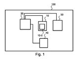
図1は、本発明の例示的な実施形態による患者の画像を生成するイメージングデバイス100を示す。図1は、カメラ装置10とデータプロセッサ30とを含むイメージングデバイス100を示す。
FIG. 1 illustrates an
イメージングデバイス100は更に、患者PのX線画像I3を提供するX線デバイス40を含む。イメージングデバイス100は更に、融合画像IEを表示する表示デバイス50を含む。
The
カメラ装置10は、第1の波長帯域を使用して患者Pの第1の画像情報I1を提供し、また、第2の波長帯域を使用して患者Pの第2の画像情報I2を提供する。第1の波長帯域と第2の波長帯域のセットとは異なり、第1及び/又は第2の画像情報は、患者PのランドマークMのランドマーク情報を含む。具体的には、少なくとも1つの波長帯域は、可視スペクトルの外側であり、より具体的には、赤外スペクトル内である。
The
本発明の例示的な実施形態によれば、カメラ装置10は、第1の画像情報I1及び第2の画像情報I2の両方を提供する1つのカメラデバイス10−0を含む。
According to an exemplary embodiment of the present invention, the
本発明の例示的な実施形態によれば、例えば図4に関して後に示され、説明されるように、カメラ装置10は、第1の画像情報I1を提供する第1のカメラデバイス10−1と、第2の画像情報I2を提供する第2のカメラデバイス10−2とを含む。第1のカメラデバイス10−1は、第1の位置において第1の画像情報I1を記録し、第2のカメラデバイス10−2は、第2の位置において第2の画像情報I2を記録する。
According to an exemplary embodiment of the present invention, as shown and described later with respect to FIG. 4, for example, the
カメラ装置10の第1及び/又は第2の波長帯域は、例えば次の通りに幾つかの波長帯域を含む可視又は非可視スペクトル内であってよい。
(1)青:0.450−0.520μm(ミクロン)
(2)緑:0.515−0.600μm
(3)赤:0.60−0.69μm
(4)可視:0.45−0.7μm
(5)赤外:0.7−1.0μm
(6)近赤外:1.0−3.0μm
(7)中赤外:3.0−50.0μm
(8)遠赤外:50.0−1000.0μm
The first and / or second wavelength bands of the
(1) Blue: 0.450-0.520 μm (micron)
(2) Green: 0.515-0.600 μm
(3) Red: 0.60-0.69 μm
(4) Visible: 0.45-0.7 μm
(5) Infrared: 0.7-1.0 μm
(6) Near infrared: 1.0-3.0 μm
(7) Mid-infrared: 3.0-50.0 μm
(8) Far infrared: 50.0-1000.0 μm
不可視光スペクトルでは、血管はより優れて光学的に分解可能である、即ち、所定の閾値よりも上のコントラストを有し、これにより、位置マーカのより正確な追跡を可能にする。 In the invisible light spectrum, blood vessels are better optically resolvable, i.e. have a contrast above a predetermined threshold, thereby allowing more accurate tracking of position markers.
本発明の例示的な実施形態によれば、三角測量と、2つの異なるカメラ位置を使用することとによって、構造の3次元モデル又は患者全体の3次元モデルの生成が改良される。 According to exemplary embodiments of the present invention, triangulation and the use of two different camera positions improves the generation of a 3D model of the structure or a 3D model of the entire patient.
本発明の例示的な実施形態によれば、データプロセッサデバイス30は、融合画像IE内の検出されたランドマークMによって特定された構造の3次元モデルを使用して、第1の画像情報I1及び第2の画像情報I2に基づく融合画像IEを生成する。
According to an exemplary embodiment of the present invention, the
位置マーカとして使用されるランドマークMを検出し、スペクトル分解することによって、位置マーカMに関連している構造の3次元位置決めが可能となる。つまり、各位置マーカは、特定の構造の一部分に割り当てられ、これにより、時間依存する一連の画像が記録された場合には、動きを追跡することが可能になり、又は、割り当てられた構造を3次元空間内に配置することが可能になる。 By detecting the landmark M used as the position marker and performing spectral decomposition, the structure related to the position marker M can be three-dimensionally positioned. That is, each position marker is assigned to a part of a specific structure, which allows tracking of the movement or recording of the assigned structure when a time-dependent series of images is recorded. It becomes possible to arrange in a three-dimensional space.
本発明の例示的な実施形態によれば、カメラデバイス10−0、10−1、10−2は、様々な(例えば6又は8以上の)取り換え可能なフィルタ、ラスター画像において1392×1040画素又は物理点の分解能を有する電荷結合デバイスCCD、又は、例えば640×512画素の分解能を有するインジウムガリウムヒ化物(InGaAs)又は任意の他の半導体センサ若しくは任意の他の画素分解能を有するセンサを有する、400乃至1000nm(ナノメートル)、1000乃至1700nm又は500nm乃至1700nmのスペクトル範囲を有するハイパースペクトル又はマルチスペクトル撮像用のハイパースペクトル又はマルチスペクトルフィルターホイールカメラであってよい。 According to exemplary embodiments of the present invention, the camera devices 10-0, 10-1, 10-2 can be configured with various (eg, 6 or more) replaceable filters, 1392 × 1040 pixels in raster images, or 400 having a charge coupled device CCD with physical point resolution or indium gallium arsenide (InGaAs) or any other semiconductor sensor with a resolution of eg 640 × 512 pixels or a sensor with any other pixel resolution It may be a hyperspectral or multispectral filter wheel camera for hyperspectral or multispectral imaging having a spectral range of 1 to 1000 nm (nanometers), 1000 to 1700 nm or 500 nm to 1700 nm.
「ハイパースペクトル撮像」との用語は、本発明によって使用される場合、可視範囲を超えて延在する電磁スペクトルの範囲から情報を収集し、処理することを指す。 The term “hyperspectral imaging”, as used by the present invention, refers to collecting and processing information from a range of the electromagnetic spectrum that extends beyond the visible range.
「マルチスペクトル撮像」との用語は、本明細書によって使用される場合、電磁スペクトルの特定の周波数における画像データを捕捉することを指す。波長は、フィルタによって、又は、特定の波長に反応する器具の使用によって分離される。即ち、複数のスペクトルが使用され、これが、「マルチスペクトル撮像」の用語の由来である。これは、赤外といった可視光範囲を超えた周波数からの光を含む。これは、この場合、上記「ハイパースペクトル撮像」の用語の「ハイパー」の用語によっても規定される。 The term “multispectral imaging” as used herein refers to capturing image data at specific frequencies of the electromagnetic spectrum. The wavelengths are separated by filters or by the use of instruments that are responsive to specific wavelengths. That is, multiple spectra are used, which is the origin of the term “multispectral imaging”. This includes light from frequencies beyond the visible light range, such as infrared. This is also defined in this case by the term “hyper” in the term “hyperspectral imaging” above.
スペクトル(マルチスペクトルであってもハイパースペクトルであっても)撮像によって、画像からの追加情報、特に人間の目がその赤、緑及び青用の受容体で捕捉することのできなかった情報を抽出することができる。 Spectral (multispectral or hyperspectral) imaging extracts additional information from the image, especially information that the human eye could not capture on its red, green, and blue receptors can do.
本発明の例示的な実施形態によれば、カメラ装置10は、10fps(1秒当たりのフレーム数)、16fps若しくは20fpsのフレームレート又は任意の他の、例えばより高速なフレームレートを有する。
According to exemplary embodiments of the present invention, the
本発明の例示的な実施形態によれば、イメージングシステム100は更に、X線デバイス40を含む。X線デバイス40は、患者PのX線画像の形式のX線画像情報I3を記録するように使用される。X線画像情報I3は更に、融合画像IEを生成するときに又は構造の3次元モデルを生成するときに使用される。
According to an exemplary embodiment of the present invention, the
本発明の例示的な実施形態によれば、イメージングシステム100は更に、融合画像IEを表示する表示デバイス50を含む。
According to an exemplary embodiment of the present invention, the
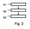
図2は、本発明の例示的な実施形態による患者の画像を生成する方法の概略的なフローチャート図を示す。患者の画像を生成する当該方法は、次のステップを含む。 FIG. 2 shows a schematic flow chart diagram of a method for generating an image of a patient according to an exemplary embodiment of the present invention. The method for generating an image of a patient includes the following steps.
上記方法の第1のステップとして、カメラ装置10によって、第1の波長帯域を使用する患者Pの第1の画像情報I1が提供される(S1)。
As a first step of the method, the
上記方法の第2のステップとして、カメラ装置10によって、第2の波長帯域を使用する患者Pの第2の画像情報I2が提供される(S2)。第1の波長帯域と第2の波長帯域とは異なる。第1及び/又は第2の画像情報は、患者PのランドマークMのランドマーク情報を含む。ランドマーク情報は、可視スペクトル外の少なくとも1つの波長帯域によって導出される。
As a second step of the method, by the
上記方法の第3のステップとして、データプロセッサ30によって、第1の画像情報I1及び第2の画像情報I2に基づく融合画像IEが生成され(S3)、融合画像IE内のランドマークMが検出される。
As a third step of the method, the
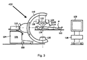
図3は、本発明の例示的な実施形態による患者の内部のX線画像を提供するX線デバイス104を含む医用イメージングデバイス400を概略的に示す。X線デバイス104(図3参照)は、車輪108によって支えられている基部フレーム106と、可動式C型アーム110と、患者114(参照符号Pとも示される)を支える手術台112とを有する。患者114は、この特定例においては人間である。
FIG. 3 schematically illustrates a
C型アーム110は、一次軸116及び二次軸118について回転可能であり、一次軸116は、手術台112の主方向に対応する方向を有し、二次軸118は、一次軸116に垂直であり、手術台112と平行である。X線源120及びX線検出器122(好適には長方形で平らな検出器)は、X線源とX線検出器とが、C型アーム110に、二次軸118について互いに反対側に配置されるように取り付けられる。
The C-
患者の外部のカメラ画像のストリームを提供する第1のカメラデバイス10−1として提供される第1のカメラ124は、C型アーム110に、X線検出器122の隣に取り付けられる。この特定の例では、第1のカメラ124は、可視スペクトル内の波長に反応する。第1のカメラ124は、画像のストリーム又は様々な時点における複数の単一画像を捕捉することもできる。
A
患者の外部のカメラ画像のストリームを提供する第2のカメラデバイス10−2として提供される第2のカメラ126は、C型アーム110に、X線検出器122の隣に取り付けられる。この特定例では、第2のカメラ126は、可視スペクトル内の波長に反応する。第2のカメラ126は、画像のストリーム又は様々な時点における複数の単一画像を捕捉することもできる。
A second camera 126, provided as a second camera device 10-2 that provides a stream of camera images external to the patient, is attached to the C-
図3を参照するに、データプロセッサ128、130は、可動マーカによって提供される空間的相関関係に基づいて、X線画像及びカメラ画像のストリームを、合成画像のストリームにレンダリングする。合成画像のストリームは、患者の内部及び患者の外部を幾何学的に重なるように表示し、更に、可動マーカ、手術野、腫瘍及び患者の体の輪郭を表示する。
Referring to FIG. 3, the
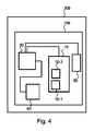
図4は、本発明の更なる例示的な実施形態による医用イメージングシステム200の概略図を示す。
FIG. 4 shows a schematic diagram of a
医用イメージングシステム200は、イメージングデバイス100の一例と、表示デバイス50の一例と、X線デバイス40の一例とを含む。表示デバイス50は、融合画像IEを表示する。X線デバイス40は、患者PのX線画像情報I3を提供する。データプロセッサ30は、第1の画像情報I1、第2の画像情報I2及びX線画像情報I3に基づいて、融合画像IEを生成する。カメラ装置10は、第1の画像情報I1を提供する第1のカメラデバイス10−1と、第2の画像情報I2を提供する第2のカメラデバイス10−2とを含む。
The
本発明の例示的な実施形態によれば、イメージングシステム200は、光学カメラをハイパースペクトルカメラと組み合わせることによって血管を自然マーカとして使用するオプションを提供する。好適には、マルチスペクトル又はハイパースペクトルカメラの波長帯域は、可視範囲に1つの波長帯域を、不可視範囲に1つの波長帯域を有する。融合画像は、各波長帯域からの2つの画像から作成され、血管を高コントラストで示す。画像の融合は、例えば部分減算を含む。
According to an exemplary embodiment of the present invention,
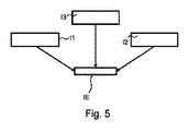
図5は、本発明を更に説明するための融合画像を生成する処理の概略図を示す。 FIG. 5 shows a schematic diagram of a process for generating a fused image for further explanation of the present invention.
融合画像IEは、例えば血管又は皮膚内の他の表面組織構造である特定された構造の3次元モデルを使用して、第1の画像情報I1と第2の画像情報I2とを融合することに基づいている。分解されたランドマークMが、データプロセッサ30によって行われる更なる処理の位置マーカとなる。
The fused image IE fuses the first image information I 1 and the second image information I 2 using a 3D model of the identified structure, for example a blood vessel or other surface tissue structure in the skin. Is based on that. The decomposed landmark M becomes a position marker for further processing performed by the
データプロセッサ30によって、融合画像IEを生成するための更なる基準として、X線画像情報I3が使用される。
The X-ray image information I 3 is used by the
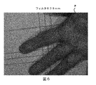
図6は、本発明を説明するための更なる画像を示す。 FIG. 6 shows a further image to illustrate the present invention.
この画像は、例えば第1のカメラデバイス10−1によって記録される。この画像は患者Pの手を捉えている。画像を記録するために、10nmの帯域幅を有する838nmのフィルタが使用される。 This image is recorded by, for example, the first camera device 10-1. This image captures the hand of patient P. An 838 nm filter with a 10 nm bandwidth is used to record the image.
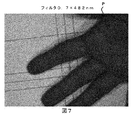
図7は、10nmの帯域幅を有する482nmのフィルタにおいて撮られ、例えば第2のカメラデバイス10−2によって記録された患者Pの手の画像を示す。係数0.7は、フィルタが、0.7倍で強度を減衰させることを示す。 FIG. 7 shows an image of the hand of patient P taken in a 482 nm filter with a bandwidth of 10 nm and recorded, for example, by the second camera device 10-2. A factor of 0.7 indicates that the filter attenuates the intensity by a factor of 0.7.
或いは、2つのカメラデバイスの代わりに、単一のマルチスペクトルカメラデバイス10−0が使用されてもよい。撮像中、例えば838nm及び482nmのフィルタが交互に使用されてもよい。 Alternatively, a single multispectral camera device 10-0 may be used instead of two camera devices. During imaging, for example, 838 nm and 482 nm filters may be used alternately.
図8は、融合フィルタを使用する、図6及び図7に示される画像の組み合わせである画像を示す。図8の画像に示される組み合わせは、例えば部分減算又は図6及び図7に示される2つの画像に関連して行われる任意の他のタイプの計算であってよい。 FIG. 8 shows an image that is a combination of the images shown in FIGS. 6 and 7 using a fusion filter. The combination shown in the image of FIG. 8 may be, for example, partial subtraction or any other type of calculation performed in connection with the two images shown in FIGS.
更なる実施形態では、3つ以上の波長において撮像を行うマルチスペクトルカメラが使用される。例えば約680nmの波長における光を通過させる第3のフィルタが追加される。本実施形態では、例えば融合画像は、様々な波長帯域において取得された画像の加重組み合わせに基づいている。加重は、好適には、関心の自然マーカを、本発明による画像追跡に十分であるコントラストレベルにおいて引き出すように調整される。 In a further embodiment, a multispectral camera is used that images at more than two wavelengths. For example, a third filter that passes light at a wavelength of about 680 nm is added. In the present embodiment, for example, the fusion image is based on a weighted combination of images acquired in various wavelength bands. The weighting is preferably adjusted to extract the natural marker of interest at a contrast level that is sufficient for image tracking according to the present invention.
なお、本発明の実施形態は、様々な主題を参照して説明されている。具体的には、方法クレームを参照して説明される実施形態もあれば、デバイスクレームを参照して説明される実施形態もある。 The embodiments of the present invention have been described with reference to various subject matters. Specifically, some embodiments are described with reference to method claims, while other embodiments are described with reference to device claims.
しかし、当業者であれば、上記説明から、特に明記されない限り、1つのタイプの主題に属する特徴の任意の組み合わせに加えて、様々な主題に関連する特徴の任意の組み合わせも、本願において開示されていると考えられることは理解するであろう。しかし、あらゆる特徴は、特徴の単なる合算以上の相乗効果を提供する限り、組み合わせることができる。 However, from the above description, any combination of features related to various subjects, as well as any combination of features belonging to one type of subject matter, is also disclosed in the present application by those skilled in the art, unless otherwise specified. You will understand that However, any feature can be combined as long as it provides a synergy that is more than just the sum of the features.
本発明は、図面及び上記説明において詳細に例示及び説明されたが、このような図及び説明は、例示に過ぎず、限定と見なされるべきではない。本発明は、開示された実施形態に限定されない。 Although the invention has been illustrated and described in detail in the drawings and foregoing description, such illustration and description are exemplary only and should not be construed as limiting. The invention is not limited to the disclosed embodiments.
開示された実施形態の他の変形態様は、図面、開示内容及び添付の請求項の検討から、請求項に係る発明を実施する当業者によって理解され、実施される。 Other variations of the disclosed embodiments will be understood and implemented by those skilled in the art practicing the claimed invention, from a study of the drawings, the disclosure, and the appended claims.
請求項において、「含む」との用語は、他の要素又はステップを排除するものではなく、また、「a」又は「an」との不定冠詞も、複数形を排除するものではない。単一のプロセッサ、コントローラ又は他のユニットが、請求項に記載される幾つかのアイテムの機能を果たしてもよい。 In the claims, the term “comprising” does not exclude other elements or steps, and the indefinite article “a” or “an” does not exclude a plurality. A single processor, controller or other unit may fulfill the functions of several items recited in the claims.
特定の手段が相互に異なる従属請求項に記載されることだけで、これらの手段の組み合わせを有利に使用することができないことを示すものではない。請求項における任意の参照符号は、範囲を限定すると解釈されるべきではない。 The mere fact that certain measures are recited in mutually different dependent claims does not indicate that a combination of these measured cannot be used to advantage. Any reference signs in the claims should not be construed as limiting the scope.
Claims (15)
第1の波長帯域を使用して前記患者の第1の画像情報を提供し、第2の波長帯域を使用して前記患者の第2の画像情報を提供するカメラ装置であって、前記第1の波長帯域と前記第2の波長帯域とは異なり、前記第1の画像情報及び/又は前記第2の画像情報は、血管又は前記患者の皮膚内の他の表面組織構造のランドマーク情報を自然マーカとして含む、前記カメラ装置と、
前記第1の画像情報及び前記第2の画像情報に基づいて、前記自然マーカを所定の閾値を上回るコントラストで示す融合画像を生成し、前記融合画像内の前記自然マーカを検出するデータプロセッサと、
を含む、イメージングデバイス。 An imaging device for generating an image of a patient, the imaging device comprising:
A camera device that provides first image information of the patient using a first wavelength band and provides second image information of the patient using a second wavelength band, the first device Unlike the second wavelength band and the second wavelength band, the first image information and / or the second image information naturally provides landmark information on blood vessels or other surface tissue structures in the patient's skin. Including the camera device as a marker;
Based on the first image information and the second image information, a data processor that generates a fused image indicating the natural marker with a contrast exceeding a predetermined threshold, and detects the natural marker in the fused image;
Including an imaging device.
前記第1のカメラデバイスは、前記第1の位置において前記第1の画像情報を記録し、前記第2のカメラデバイスは、前記第2の位置において前記第2の画像情報を記録する、請求項2に記載のイメージングデバイス。 The camera apparatus includes a first camera device that provides the first image information, and a second camera device that provides the second image information,
The first camera device records the first image information at the first position, and the second camera device records the second image information at the second position. The imaging device according to 2.
前記融合画像を表示する表示デバイスと、
前記患者のX線画像情報を提供するX線デバイスと、
を含み、
前記データプロセッサは、前記第1の画像情報と、前記第2の画像情報と、前記X線画像情報とに基づいて、前記融合画像を生成する、医用イメージングシステム。 An imaging device according to any one of claims 1 to 11,
A display device for displaying the fused image;
An X-ray device providing X-ray image information of the patient;
Including
The data processor is a medical imaging system that generates the fusion image based on the first image information, the second image information, and the X-ray image information.
a)カメラ装置によって、第1の波長帯域を使用して、前記患者の第1の画像情報を提供するステップと、
b)前記カメラ装置によって、第2の波長帯域を使用して、前記患者の第2の画像情報を提供するステップと、を含み、
前記第1の波長帯域と前記第2の波長帯域とは異なり、前記第1の画像情報及び/又は前記第2の画像情報は、血管又は前記患者の皮膚内の他の表面組織構造のランドマーク情報を前記自然マーカとして含み、
c)データプロセッサによって、前記第1の画像情報と、前記第2の画像情報とに基づいて、所定閾値を上回るコントラストで自然マーカを示す融合画像を生成し、前記融合画像内の前記自然マーカを検出するステップを含む、
方法。 A method for generating an image of a patient comprising:
a) providing a first image information of the patient using a first wavelength band by a camera device;
b) providing second image information of the patient using the second wavelength band by the camera device;
Unlike the first wavelength band and the second wavelength band, the first image information and / or the second image information is a landmark of a blood vessel or other surface tissue structure in the patient's skin Including information as the natural marker,
c) Based on the first image information and the second image information, a data processor generates a fused image indicating a natural marker with a contrast exceeding a predetermined threshold, and the natural marker in the fused image is Including the step of detecting,
Method.
Applications Claiming Priority (3)
| Application Number | Priority Date | Filing Date | Title |
|---|---|---|---|
| EP14195180.6 | 2014-11-27 | ||
| EP14195180 | 2014-11-27 | ||
| PCT/EP2015/077707 WO2016083483A1 (en) | 2014-11-27 | 2015-11-26 | Imaging device and method for generating an image of a patient |
Publications (2)
| Publication Number | Publication Date |
|---|---|
| JP2018501839A true JP2018501839A (en) | 2018-01-25 |
| JP2018501839A5 JP2018501839A5 (en) | 2019-01-10 |
Family
ID=52103029
Family Applications (1)
| Application Number | Title | Priority Date | Filing Date |
|---|---|---|---|
| JP2017527856A Ceased JP2018501839A (en) | 2014-11-27 | 2015-11-26 | Imaging device and method for generating an image of a patient |
Country Status (5)
| Country | Link |
|---|---|
| US (1) | US11033188B2 (en) |
| EP (1) | EP3223685A1 (en) |
| JP (1) | JP2018501839A (en) |
| CN (1) | CN106999131A (en) |
| WO (1) | WO2016083483A1 (en) |
Families Citing this family (17)
| Publication number | Priority date | Publication date | Assignee | Title |
|---|---|---|---|---|
| CA3023772A1 (en) | 2016-05-13 | 2017-11-16 | Smith & Nephew Plc | Sensor enabled wound monitoring and therapy apparatus |
| US10963991B2 (en) * | 2016-07-25 | 2021-03-30 | Nec Corporation | Information processing device, information processing method, and recording medium |
| US11690570B2 (en) | 2017-03-09 | 2023-07-04 | Smith & Nephew Plc | Wound dressing, patch member and method of sensing one or more wound parameters |
| EP3592230A1 (en) | 2017-03-09 | 2020-01-15 | Smith & Nephew PLC | Apparatus and method for imaging blood in a target region of tissue |
| JP7235673B2 (en) | 2017-04-11 | 2023-03-08 | スミス アンド ネフュー ピーエルシー | Component placement and stress relief for sensor-enabled wound dressings |
| CA3062989A1 (en) | 2017-05-15 | 2018-11-22 | Smith & Nephew Plc | Wound analysis device and method |
| CA3066073A1 (en) | 2017-06-23 | 2018-12-27 | Smith & Nephew Plc | Positioning of sensors for sensor enabled wound monitoring or therapy |
| GB201804502D0 (en) | 2018-03-21 | 2018-05-02 | Smith & Nephew | Biocompatible encapsulation and component stress relief for sensor enabled negative pressure wound therapy dressings |
| GB201809007D0 (en) | 2018-06-01 | 2018-07-18 | Smith & Nephew | Restriction of sensor-monitored region for sensor-enabled wound dressings |
| EP3664859A2 (en) | 2017-08-10 | 2020-06-17 | Smith & Nephew plc | Positioning of sensors for sensor enabled wound monitoring or therapy |
| GB201804971D0 (en) | 2018-03-28 | 2018-05-09 | Smith & Nephew | Electrostatic discharge protection for sensors in wound therapy |
| WO2019048624A1 (en) | 2017-09-10 | 2019-03-14 | Smith & Nephew Plc | Systems and methods for inspection of encapsulation and components in sensor equipped wound dressings |
| GB201718870D0 (en) | 2017-11-15 | 2017-12-27 | Smith & Nephew Inc | Sensor enabled wound therapy dressings and systems |
| JP7282079B2 (en) | 2017-09-27 | 2023-05-26 | スミス アンド ネフュー ピーエルシー | PH Sensing for Sensor-Enabled Negative Pressure Wound Monitoring and Therapy Devices |
| WO2019072531A1 (en) | 2017-09-28 | 2019-04-18 | Smith & Nephew Plc | Neurostimulation and monitoring using sensor enabled wound monitoring and therapy apparatus |
| EP3709943A1 (en) | 2017-11-15 | 2020-09-23 | Smith & Nephew PLC | Integrated sensor enabled wound monitoring and/or therapy dressings and systems |
| WO2020053290A1 (en) | 2018-09-12 | 2020-03-19 | Smith & Nephew Plc | Device, apparatus and method of determining skin perfusion pressure |
Citations (9)
| Publication number | Priority date | Publication date | Assignee | Title |
|---|---|---|---|---|
| JPH0889501A (en) * | 1994-09-21 | 1996-04-09 | Hitachi Medical Corp | Medical image diagnostic device |
| JP2006102360A (en) * | 2004-10-08 | 2006-04-20 | Matsushita Electric Ind Co Ltd | Living body information presentation device |
| US20070158569A1 (en) * | 2000-01-19 | 2007-07-12 | Luminetx Technologies Corporation | Method and Apparatus for Projection of Subsurface Structure onto an Object's Surface |
| WO2008130903A1 (en) * | 2007-04-17 | 2008-10-30 | Mikos, Ltd. | System and method for using three dimensional infrared imaging for libraries of standardized medical imagery |
| WO2012026597A1 (en) * | 2010-08-27 | 2012-03-01 | ソニー株式会社 | Image processing apparatus and method |
| US20120071765A1 (en) * | 2010-09-17 | 2012-03-22 | Optimum Technologies, Inc. | Digital Mapping System and Method |
| JP2012107942A (en) * | 2010-11-16 | 2012-06-07 | Olympus Corp | Imaging device |
| JP2013244343A (en) * | 2012-05-29 | 2013-12-09 | Mitsubishi Electric Engineering Co Ltd | Biological information presentation device and biological information presentation method |
| US20140161307A1 (en) * | 2012-12-11 | 2014-06-12 | Xerox Corporation | Methods and Systems for Vascular Pattern Localization Using Temporal Features |
Family Cites Families (22)
| Publication number | Priority date | Publication date | Assignee | Title |
|---|---|---|---|---|
| US6496594B1 (en) | 1998-10-22 | 2002-12-17 | Francine J. Prokoski | Method and apparatus for aligning and comparing images of the face and body from different imagers |
| AU5783900A (en) * | 1999-07-02 | 2001-01-22 | Hypermed, Inc. | Integrated imaging apparatus |
| US7519210B2 (en) * | 2004-09-09 | 2009-04-14 | Raphael Hirsch | Method of assessing localized shape and temperature of the human body |
| US8548570B2 (en) | 2004-11-29 | 2013-10-01 | Hypermed Imaging, Inc. | Hyperspectral imaging of angiogenesis |
| US8270689B2 (en) | 2006-09-12 | 2012-09-18 | Carestream Health, Inc. | Apparatus for caries detection |
| JP5143471B2 (en) * | 2007-05-08 | 2013-02-13 | 株式会社日立製作所 | Imaging device |
| US20090318815A1 (en) | 2008-05-23 | 2009-12-24 | Michael Barnes | Systems and methods for hyperspectral medical imaging |
| ES2341079B1 (en) * | 2008-12-11 | 2011-07-13 | Fundacio Clinic Per A La Recerca Biomedica | EQUIPMENT FOR IMPROVED VISION BY INFRARED VASCULAR STRUCTURES, APPLICABLE TO ASSIST PHYTOSCOPIC, LAPAROSCOPIC AND ENDOSCOPIC INTERVENTIONS AND SIGNAL TREATMENT PROCESS TO IMPROVE SUCH VISION. |
| JP5604442B2 (en) | 2008-12-11 | 2014-10-08 | コーニンクレッカ フィリップス エヌ ヴェ | System for generating images of internal and external surfaces of a patient and method of operating the same |
| RU2556518C2 (en) | 2009-05-13 | 2015-07-10 | Конинклейке Филипс Электроникс Н.В. | System for detecting global displacement in patient during visualisation procedures |
| WO2011084528A1 (en) * | 2009-12-15 | 2011-07-14 | Emory University Office Of Technology Transfer | System and method for providing real-time anatomical guidance in a diagnostic or therapeutic procedure |
| CN101763461B (en) * | 2009-12-31 | 2015-10-21 | 马宇尘 | The method and system of arranging pinhead combined with vessel imaging |
| JP5800175B2 (en) | 2010-02-05 | 2015-10-28 | ソニー株式会社 | Image processing apparatus, image processing method, program, and electronic apparatus |
| KR101381033B1 (en) | 2010-03-10 | 2014-04-04 | 이엘씨 매니지먼트 엘엘씨 | System for skin treatment analysis using spectral image data to generate 3d rgb model |
| US20140031668A1 (en) | 2010-09-08 | 2014-01-30 | Disruptive Navigational Technologies, Llc | Surgical and Medical Instrument Tracking Using a Depth-Sensing Device |
| CN101984928B (en) * | 2010-09-29 | 2012-06-13 | 北京大学 | Multi-mode molecular tomography system |
| DE102011075904A1 (en) * | 2011-05-16 | 2012-11-22 | Siemens Aktiengesellschaft | A method for providing an image data set with suppressed over-field artifacts and X-ray image capture device |
| DE102011083876B4 (en) * | 2011-09-30 | 2018-12-27 | Siemens Healthcare Gmbh | Method for controlling the movement of an X-ray device and X-ray system |
| US8761476B2 (en) | 2011-11-09 | 2014-06-24 | The Johns Hopkins University | Hyperspectral imaging for detection of skin related conditions |
| CN102663355A (en) * | 2012-03-27 | 2012-09-12 | 天津理工大学 | Identification system based on combination of dorsal hand vein and hand shape and method thereof |
| JP6360052B2 (en) | 2012-07-17 | 2018-07-18 | コーニンクレッカ フィリップス エヌ ヴェKoninklijke Philips N.V. | Imaging system and method enabling instrument guidance |
| CN103345735B (en) * | 2013-07-16 | 2015-12-09 | 上海交通大学 | A kind of compression space-time multi-sensor fusion tracking based on Kalman filter |
-
2015
- 2015-11-26 CN CN201580064882.0A patent/CN106999131A/en active Pending
- 2015-11-26 WO PCT/EP2015/077707 patent/WO2016083483A1/en active Application Filing
- 2015-11-26 JP JP2017527856A patent/JP2018501839A/en not_active Ceased
- 2015-11-26 US US15/531,019 patent/US11033188B2/en active Active
- 2015-11-26 EP EP15813703.4A patent/EP3223685A1/en not_active Withdrawn
Patent Citations (9)
| Publication number | Priority date | Publication date | Assignee | Title |
|---|---|---|---|---|
| JPH0889501A (en) * | 1994-09-21 | 1996-04-09 | Hitachi Medical Corp | Medical image diagnostic device |
| US20070158569A1 (en) * | 2000-01-19 | 2007-07-12 | Luminetx Technologies Corporation | Method and Apparatus for Projection of Subsurface Structure onto an Object's Surface |
| JP2006102360A (en) * | 2004-10-08 | 2006-04-20 | Matsushita Electric Ind Co Ltd | Living body information presentation device |
| WO2008130903A1 (en) * | 2007-04-17 | 2008-10-30 | Mikos, Ltd. | System and method for using three dimensional infrared imaging for libraries of standardized medical imagery |
| WO2012026597A1 (en) * | 2010-08-27 | 2012-03-01 | ソニー株式会社 | Image processing apparatus and method |
| US20120071765A1 (en) * | 2010-09-17 | 2012-03-22 | Optimum Technologies, Inc. | Digital Mapping System and Method |
| JP2012107942A (en) * | 2010-11-16 | 2012-06-07 | Olympus Corp | Imaging device |
| JP2013244343A (en) * | 2012-05-29 | 2013-12-09 | Mitsubishi Electric Engineering Co Ltd | Biological information presentation device and biological information presentation method |
| US20140161307A1 (en) * | 2012-12-11 | 2014-06-12 | Xerox Corporation | Methods and Systems for Vascular Pattern Localization Using Temporal Features |
Also Published As
| Publication number | Publication date |
|---|---|
| WO2016083483A1 (en) | 2016-06-02 |
| CN106999131A (en) | 2017-08-01 |
| US11033188B2 (en) | 2021-06-15 |
| US20170319075A1 (en) | 2017-11-09 |
| EP3223685A1 (en) | 2017-10-04 |
Similar Documents
| Publication | Publication Date | Title |
|---|---|---|
| JP2018501839A (en) | Imaging device and method for generating an image of a patient | |
| EP3138526B1 (en) | Augmented surgical reality environment system | |
| JP6509906B2 (en) | Method of operating a medical device | |
| JP6348078B2 (en) | Branch structure determination apparatus, operation method of branch structure determination apparatus, and branch structure determination program | |
| Lin et al. | Video‐based 3D reconstruction, laparoscope localization and deformation recovery for abdominal minimally invasive surgery: a survey | |
| US10170155B2 (en) | Motion information display apparatus and method | |
| KR101572487B1 (en) | System and Method For Non-Invasive Patient-Image Registration | |
| JP6045417B2 (en) | Image processing apparatus, electronic apparatus, endoscope apparatus, program, and operation method of image processing apparatus | |
| US20160086380A1 (en) | Hyperspectral imager | |
| JP2018501839A5 (en) | ||
| US20160004917A1 (en) | Output control method, image processing apparatus, and information processing apparatus | |
| US20230267613A1 (en) | Medical image processing apparatus and method | |
| JP2006014928A (en) | Method, device and program for displaying image | |
| WO2017042171A1 (en) | Apparatus for imaging in a medical treatment | |
| WO2019130868A1 (en) | Image processing device, processor device, endoscope system, image processing method, and program | |
| JP6472606B2 (en) | X-ray diagnostic equipment | |
| Chen et al. | Collaborative use of RGB and thermal imaging for remote breathing rate measurement under realistic conditions | |
| US9867586B2 (en) | Stereo X-ray tube based suppression of outside body high contrast objects | |
| Sánchez et al. | Navigation path retrieval from videobronchoscopy using bronchial branches | |
| US10402991B2 (en) | Device and method for registration of two images | |
| US11056149B2 (en) | Medical image storage and reproduction apparatus, method, and program | |
| Strakowska et al. | Cross-correlation based movement correction method for biomedical dynamic infrared imaging | |
| Johnson et al. | Hierarchical structure from motion optical flow algorithms to harvest three-dimensional features from two-dimensional neuro-endoscopic images | |
| Manni et al. | Multispectral image analysis for patient tissue tracking during complex interventions | |
| US10049480B2 (en) | Image alignment device, method, and program |
Legal Events
| Date | Code | Title | Description |
|---|---|---|---|
| A521 | Request for written amendment filed |
Free format text: JAPANESE INTERMEDIATE CODE: A523 Effective date: 20181122 |
|
| A621 | Written request for application examination |
Free format text: JAPANESE INTERMEDIATE CODE: A621 Effective date: 20181122 |
|
| A977 | Report on retrieval |
Free format text: JAPANESE INTERMEDIATE CODE: A971007 Effective date: 20190726 |
|
| A131 | Notification of reasons for refusal |
Free format text: JAPANESE INTERMEDIATE CODE: A131 Effective date: 20190802 |
|
| A521 | Request for written amendment filed |
Free format text: JAPANESE INTERMEDIATE CODE: A523 Effective date: 20191029 |
|
| A131 | Notification of reasons for refusal |
Free format text: JAPANESE INTERMEDIATE CODE: A131 Effective date: 20200330 |
|
| A131 | Notification of reasons for refusal |
Free format text: JAPANESE INTERMEDIATE CODE: A131 Effective date: 20201208 |
|
| A601 | Written request for extension of time |
Free format text: JAPANESE INTERMEDIATE CODE: A601 Effective date: 20210304 |
|
| A521 | Request for written amendment filed |
Free format text: JAPANESE INTERMEDIATE CODE: A523 Effective date: 20210604 |
|
| A01 | Written decision to grant a patent or to grant a registration (utility model) |
Free format text: JAPANESE INTERMEDIATE CODE: A01 Effective date: 20211122 |
|
| A045 | Written measure of dismissal of application [lapsed due to lack of payment] |
Free format text: JAPANESE INTERMEDIATE CODE: A045 Effective date: 20220328 |