JP2018500836A - Mechanism for providing LTE voice, Internet, and EMBMS services over Ethernet for connected home architecture - Google Patents
Mechanism for providing LTE voice, Internet, and EMBMS services over Ethernet for connected home architecture Download PDFInfo
- Publication number
- JP2018500836A JP2018500836A JP2017534777A JP2017534777A JP2018500836A JP 2018500836 A JP2018500836 A JP 2018500836A JP 2017534777 A JP2017534777 A JP 2017534777A JP 2017534777 A JP2017534777 A JP 2017534777A JP 2018500836 A JP2018500836 A JP 2018500836A
- Authority
- JP
- Japan
- Prior art keywords
- gateway
- message
- network device
- connection
- secure connection
- Prior art date
- Legal status (The legal status is an assumption and is not a legal conclusion. Google has not performed a legal analysis and makes no representation as to the accuracy of the status listed.)
- Pending
Links
- 230000007246 mechanism Effects 0.000 title description 4
- 230000004044 response Effects 0.000 claims abstract description 125
- 238000000034 method Methods 0.000 claims abstract description 64
- 238000004891 communication Methods 0.000 claims abstract description 63
- 230000005540 biological transmission Effects 0.000 claims description 21
- 238000012544 monitoring process Methods 0.000 claims description 8
- 238000004590 computer program Methods 0.000 abstract description 3
- 238000012545 processing Methods 0.000 description 36
- 238000010586 diagram Methods 0.000 description 27
- 230000006870 function Effects 0.000 description 20
- 238000005516 engineering process Methods 0.000 description 10
- 230000008859 change Effects 0.000 description 5
- 238000013461 design Methods 0.000 description 5
- 238000007726 management method Methods 0.000 description 5
- 230000008569 process Effects 0.000 description 5
- 238000013519 translation Methods 0.000 description 5
- 230000009471 action Effects 0.000 description 4
- 238000001914 filtration Methods 0.000 description 4
- 230000001413 cellular effect Effects 0.000 description 3
- 230000000977 initiatory effect Effects 0.000 description 3
- 230000004048 modification Effects 0.000 description 3
- 238000012986 modification Methods 0.000 description 3
- 230000002093 peripheral effect Effects 0.000 description 3
- 238000001228 spectrum Methods 0.000 description 3
- 101001018494 Homo sapiens Pro-MCH Proteins 0.000 description 2
- 102100033721 Pro-MCH Human genes 0.000 description 2
- 239000000284 extract Substances 0.000 description 2
- 230000006872 improvement Effects 0.000 description 2
- 230000007774 longterm Effects 0.000 description 2
- 230000008520 organization Effects 0.000 description 2
- 230000011664 signaling Effects 0.000 description 2
- 230000001360 synchronised effect Effects 0.000 description 2
- 238000012384 transportation and delivery Methods 0.000 description 2
- 230000005856 abnormality Effects 0.000 description 1
- 230000004913 activation Effects 0.000 description 1
- 238000013459 approach Methods 0.000 description 1
- 230000008901 benefit Effects 0.000 description 1
- 239000012141 concentrate Substances 0.000 description 1
- 125000004122 cyclic group Chemical group 0.000 description 1
- 230000009849 deactivation Effects 0.000 description 1
- 230000001934 delay Effects 0.000 description 1
- 238000001514 detection method Methods 0.000 description 1
- 230000000694 effects Effects 0.000 description 1
- 230000007257 malfunction Effects 0.000 description 1
- 238000010295 mobile communication Methods 0.000 description 1
- 230000003287 optical effect Effects 0.000 description 1
- 238000013468 resource allocation Methods 0.000 description 1
Images


Classifications
-
- H—ELECTRICITY
- H04—ELECTRIC COMMUNICATION TECHNIQUE
- H04L—TRANSMISSION OF DIGITAL INFORMATION, e.g. TELEGRAPHIC COMMUNICATION
- H04L65/00—Network arrangements, protocols or services for supporting real-time applications in data packet communication
- H04L65/60—Network streaming of media packets
- H04L65/61—Network streaming of media packets for supporting one-way streaming services, e.g. Internet radio
- H04L65/611—Network streaming of media packets for supporting one-way streaming services, e.g. Internet radio for multicast or broadcast
-
- H—ELECTRICITY
- H04—ELECTRIC COMMUNICATION TECHNIQUE
- H04L—TRANSMISSION OF DIGITAL INFORMATION, e.g. TELEGRAPHIC COMMUNICATION
- H04L65/00—Network arrangements, protocols or services for supporting real-time applications in data packet communication
- H04L65/10—Architectures or entities
- H04L65/102—Gateways
-
- H—ELECTRICITY
- H04—ELECTRIC COMMUNICATION TECHNIQUE
- H04L—TRANSMISSION OF DIGITAL INFORMATION, e.g. TELEGRAPHIC COMMUNICATION
- H04L12/00—Data switching networks
- H04L12/02—Details
- H04L12/16—Arrangements for providing special services to substations
- H04L12/18—Arrangements for providing special services to substations for broadcast or conference, e.g. multicast
-
- H—ELECTRICITY
- H04—ELECTRIC COMMUNICATION TECHNIQUE
- H04L—TRANSMISSION OF DIGITAL INFORMATION, e.g. TELEGRAPHIC COMMUNICATION
- H04L63/00—Network architectures or network communication protocols for network security
- H04L63/08—Network architectures or network communication protocols for network security for authentication of entities
- H04L63/0876—Network architectures or network communication protocols for network security for authentication of entities based on the identity of the terminal or configuration, e.g. MAC address, hardware or software configuration or device fingerprint
-
- H—ELECTRICITY
- H04—ELECTRIC COMMUNICATION TECHNIQUE
- H04L—TRANSMISSION OF DIGITAL INFORMATION, e.g. TELEGRAPHIC COMMUNICATION
- H04L63/00—Network architectures or network communication protocols for network security
- H04L63/16—Implementing security features at a particular protocol layer
- H04L63/166—Implementing security features at a particular protocol layer at the transport layer
-
- H—ELECTRICITY
- H04—ELECTRIC COMMUNICATION TECHNIQUE
- H04L—TRANSMISSION OF DIGITAL INFORMATION, e.g. TELEGRAPHIC COMMUNICATION
- H04L65/00—Network arrangements, protocols or services for supporting real-time applications in data packet communication
- H04L65/1066—Session management
- H04L65/1069—Session establishment or de-establishment
-
- H—ELECTRICITY
- H04—ELECTRIC COMMUNICATION TECHNIQUE
- H04W—WIRELESS COMMUNICATION NETWORKS
- H04W12/00—Security arrangements; Authentication; Protecting privacy or anonymity
- H04W12/06—Authentication
-
- H—ELECTRICITY
- H04—ELECTRIC COMMUNICATION TECHNIQUE
- H04W—WIRELESS COMMUNICATION NETWORKS
- H04W12/00—Security arrangements; Authentication; Protecting privacy or anonymity
- H04W12/06—Authentication
- H04W12/069—Authentication using certificates or pre-shared keys
-
- H—ELECTRICITY
- H04—ELECTRIC COMMUNICATION TECHNIQUE
- H04W—WIRELESS COMMUNICATION NETWORKS
- H04W12/00—Security arrangements; Authentication; Protecting privacy or anonymity
- H04W12/08—Access security
-
- H—ELECTRICITY
- H04—ELECTRIC COMMUNICATION TECHNIQUE
- H04W—WIRELESS COMMUNICATION NETWORKS
- H04W12/00—Security arrangements; Authentication; Protecting privacy or anonymity
- H04W12/08—Access security
- H04W12/088—Access security using filters or firewalls
-
- H—ELECTRICITY
- H04—ELECTRIC COMMUNICATION TECHNIQUE
- H04W—WIRELESS COMMUNICATION NETWORKS
- H04W36/00—Hand-off or reselection arrangements
- H04W36/14—Reselecting a network or an air interface
-
- H—ELECTRICITY
- H04—ELECTRIC COMMUNICATION TECHNIQUE
- H04W—WIRELESS COMMUNICATION NETWORKS
- H04W4/00—Services specially adapted for wireless communication networks; Facilities therefor
- H04W4/06—Selective distribution of broadcast services, e.g. multimedia broadcast multicast service [MBMS]; Services to user groups; One-way selective calling services
-
- H—ELECTRICITY
- H04—ELECTRIC COMMUNICATION TECHNIQUE
- H04W—WIRELESS COMMUNICATION NETWORKS
- H04W76/00—Connection management
- H04W76/40—Connection management for selective distribution or broadcast
-
- H—ELECTRICITY
- H04—ELECTRIC COMMUNICATION TECHNIQUE
- H04W—WIRELESS COMMUNICATION NETWORKS
- H04W8/00—Network data management
- H04W8/005—Discovery of network devices, e.g. terminals
-
- H—ELECTRICITY
- H04—ELECTRIC COMMUNICATION TECHNIQUE
- H04L—TRANSMISSION OF DIGITAL INFORMATION, e.g. TELEGRAPHIC COMMUNICATION
- H04L61/00—Network arrangements, protocols or services for addressing or naming
- H04L61/09—Mapping addresses
- H04L61/25—Mapping addresses of the same type
- H04L61/2503—Translation of Internet protocol [IP] addresses
- H04L61/2514—Translation of Internet protocol [IP] addresses between local and global IP addresses
-
- H—ELECTRICITY
- H04—ELECTRIC COMMUNICATION TECHNIQUE
- H04L—TRANSMISSION OF DIGITAL INFORMATION, e.g. TELEGRAPHIC COMMUNICATION
- H04L61/00—Network arrangements, protocols or services for addressing or naming
- H04L61/50—Address allocation
- H04L61/5007—Internet protocol [IP] addresses
- H04L61/5014—Internet protocol [IP] addresses using dynamic host configuration protocol [DHCP] or bootstrap protocol [BOOTP]
-
- H—ELECTRICITY
- H04—ELECTRIC COMMUNICATION TECHNIQUE
- H04W—WIRELESS COMMUNICATION NETWORKS
- H04W36/00—Hand-off or reselection arrangements
- H04W36/14—Reselecting a network or an air interface
- H04W36/142—Reselecting a network or an air interface over the same radio air interface technology
Abstract
ネットワークにおける通信のための方法、装置、およびコンピュータプログラム製品。装置は、ネットワークデバイスにマルチキャストメッセージを送る。マルチキャストメッセージは、ネットワークデバイスの未知のIPアドレスの発見を容易にする。装置は、マルチキャストメッセージに応答して第1の応答メッセージがネットワークデバイスから受信されるかどうかを決定し、第1の応答メッセージがネットワークデバイスから受信されるとき、第1の応答メッセージからネットワークデバイスのIPアドレスを決定する。装置は、決定されたIPアドレスを使用して、ネットワークデバイスとセキュア接続を確立する。装置は、装置とネットワークデバイスとの間の失敗したエンド・ツー・エンドリンクを検出するために、ネットワークデバイスにリンクステータスチェックメッセージを送る。【選択図】 図7A method, apparatus, and computer program product for communication in a network. The device sends a multicast message to the network device. Multicast messages facilitate the discovery of unknown IP addresses of network devices. The apparatus determines whether a first response message is received from the network device in response to the multicast message, and when the first response message is received from the network device, from the first response message, the network device's Determine the IP address. The device establishes a secure connection with the network device using the determined IP address. The device sends a link status check message to the network device to detect a failed end-to-end link between the device and the network device. [Selection] Figure 7
Description
[0001]本願は、全体が参照により本明細書に明確に組み込まれる、2014年12月30日に出願された「MECHANISM TO PROVIDE LTE VOICE, INTERNET AND EMBMS SERVICES OVER ETHERNET FOR CONNECTED HOME ARCHITECTURE」と題する米国特許出願第14/586,878号の利益を主張する。
[0001] This application is a United States application entitled “MECHANISM TO PROVIDE LTE VOICE, INTERNET AND EMBMS SERVICES OVER ETHERNET FOR CONNECTED HOME ARCHITECTURE,” filed Dec. 30, 2014, which is expressly incorporated herein by reference in its entirety. Claims the benefit of
[0002]本開示は一般に、通信システムに関し、より具体的には、コネクテッドホームアーキテクチャに対して、イーサネット(登録商標)上で、ロングタームエボリューション(LTE(登録商標))音声、インターネット、及びエボルブドマルチメディアブロードキャストマルチキャストサービス(eMBMS)サービスを提供するためのメカニズムに関する。 [0002] The present disclosure relates generally to communication systems, and more particularly to Long Term Evolution (LTE) voice, Internet, and evolved over Ethernet for connected home architectures. The present invention relates to a mechanism for providing a multimedia broadcast multicast service (eMBMS) service.
[0003]ワイヤレス通信システムは、電話通信、ビデオ、データ、メッセージング、およびブロードキャストといった様々な電気通信サービスを提供するために広く展開されている。典型的なワイヤレス通信システムは、利用可能なシステムリソース(たとえば、帯域幅、伝送電力)を共有することによって複数のユーザとの通信をサポートする能力がある多元接続技術を用い得る。このような多元接続技術の例には、符号分割多元接続(CDMA)システム、時分割多元接続(TDMA)システム、周波数分割多元接続(FDMA)システム、直交周波数分割多元接続(OFDMA)システム、単一キャリア周波数分割多元接続(SC−FDMA)システム、および時分割同期符号分割多元接続(TD−SCDMA)システムが含まれる。 [0003] Wireless communication systems are widely deployed to provide various telecommunication services such as telephony, video, data, messaging, and broadcast. A typical wireless communication system may employ multiple access technologies that are capable of supporting communication with multiple users by sharing available system resources (eg, bandwidth, transmission power). Examples of such multiple access techniques include code division multiple access (CDMA) systems, time division multiple access (TDMA) systems, frequency division multiple access (FDMA) systems, orthogonal frequency division multiple access (OFDMA) systems, single Carrier frequency division multiple access (SC-FDMA) systems and time division synchronous code division multiple access (TD-SCDMA) systems are included.
[0004]これらの多元接続技術は、異なるワイヤレスデバイスが都市、全国、地域、さらには地球規模で通信することを可能にする共通プロトコルを提供するために、様々な電気通信規格に採用されている。新興の電気通信規格の例は、ロングタームエボリューション(LTE)である。LTEは、第3世代パートナーシッププロジェクト(3GPP(登録商標))によって公表されたユニバーサルモバイル電気通信システム(UMTS)モバイル規格の拡張のセットである。LTEは、スペクトル効率を改善すること、コストを下げること、サービスを改善すること、新たなスペクトルを利用すること、および、ダウンリンク(DL)上ではOFDMAを使用し、アップリンク(UL)上ではSC−FDMAを使用する他のオープン規格および多入力多出力(MIMO)アンテナ技術とより良く統合することによって、モバイルブロードバンドインターネットアクセスをより良好にサポートするように設計される。しかしながら、モバイルブロードバンドアクセスに対する需要は増加し続けているため、LTE技術のさらなる改善が必要である。好ましくは、これらの改善は、これらの技術を用いる他の多元接続技術および電気通信規格に適用可能であるべきである。 [0004] These multiple access technologies have been adopted by various telecommunication standards to provide a common protocol that allows different wireless devices to communicate in urban, national, regional and even global scales. . An example of an emerging telecommunications standard is Long Term Evolution (LTE). LTE is a set of extensions to the Universal Mobile Telecommunications System (UMTS) mobile standard published by the 3rd Generation Partnership Project (3GPP®). LTE improves spectrum efficiency, lowers costs, improves service, utilizes new spectrum, and uses OFDMA on the downlink (DL) and on the uplink (UL). It is designed to better support mobile broadband Internet access by better integrating with other open standards and multiple input multiple output (MIMO) antenna technologies that use SC-FDMA. However, as demand for mobile broadband access continues to increase, further improvements in LTE technology are needed. Preferably, these improvements should be applicable to other multiple access technologies and telecommunications standards that use these technologies.
[0005]本開示のある態様では、方法、コンピュータプログラム製品、および装置が提供される。方法は、ネットワークデバイスにマルチキャストメッセージを送ることと、ここで、ネットワークデバイスのインターネットプロトコル(IP)アドレスは、未知である、マルチキャストメッセージに応答して、第1の応答メッセージがネットワークデバイスから受信されるかどうかを決定することと、第1の応答メッセージがネットワークデバイスから受信されるとき、第1の応答メッセージからネットワークデバイスのIPアドレスを決定することと、決定されたIPアドレスを使用してネットワークデバイスとセキュア接続を確立することとを含む。 [0005] In certain aspects of the present disclosure, methods, computer program products, and apparatus are provided. The method sends a multicast message to the network device, where the Internet Protocol (IP) address of the network device is unknown, in response to the multicast message, a first response message is received from the network device. Determining when the first response message is received from the network device, determining the IP address of the network device from the first response message, and using the determined IP address to the network device And establishing a secure connection.
[0006]装置は、ネットワークデバイスにマルチキャストメッセージを送る。マルチキャストメッセージは、ネットワークデバイスの発見を容易にし、ここで、ネットワークデバイスのIPアドレスは、未知である。装置は、マルチキャストメッセージに応答して第1の応答メッセージがネットワークデバイスから受信されるかどうかを決定し、第1の応答メッセージがネットワークデバイスから受信されるとき、第1の応答メッセージからネットワークデバイスのIPアドレスを決定する。装置は、決定されたIPアドレスを使用して、ネットワークデバイスとセキュア接続を確立する。 [0006] The apparatus sends a multicast message to the network device. Multicast messages facilitate the discovery of network devices, where the IP address of the network device is unknown. The apparatus determines whether a first response message is received from the network device in response to the multicast message, and when the first response message is received from the network device, from the first response message, the network device's Determine the IP address. The device establishes a secure connection with the network device using the determined IP address.
[0007]本開示のある態様では、方法、コンピュータプログラム製品、および装置が提供される。たとえば、方法は、ネットワークデバイスによって実行され得る。方法は、ゲートウェイからのマルチキャストメッセージについて第1のポートをモニタすることと、マルチキャストメッセージが受信されるとき、ゲートウェイに第1の応答メッセージを送ることと、第2のポート上でセキュア接続の確立を開始する(initiate)信号を受信することと、ゲートウェイとセキュア接続を確立することとを含む。装置は、基地局から、MBMSデータ、インターネットトラフィック、および/またはIMSトラフィックを受信するように構成される。 [0007] Certain aspects of the present disclosure provide methods, computer program products, and apparatus. For example, the method may be performed by a network device. The method includes monitoring a first port for a multicast message from the gateway, sending a first response message to the gateway when the multicast message is received, and establishing a secure connection on the second port. Receiving an initiate signal and establishing a secure connection with the gateway. The device is configured to receive MBMS data, Internet traffic, and / or IMS traffic from the base station.
[0008]装置は、ゲートウェイからのマルチキャストメッセージについて第1のポートをモニタし、マルチキャストメッセージが受信されるとき、ゲートウェイに第1の応答メッセージを送る。装置は、第2のポート上でセキュア接続の確立を開始する信号を受信し、ゲートウェイとセキュア接続を確立する。 [0008] The apparatus monitors the first port for a multicast message from the gateway and sends a first response message to the gateway when the multicast message is received. The device receives a signal to initiate establishment of a secure connection on the second port and establishes a secure connection with the gateway.
[0027]添付の図面に関連して以下に示される詳細な説明は、様々な構成の説明を意図したものであり、本明細書で説明される概念が実施され得る構成を表すことを意図したものではない。詳細な説明は、様々な概念の完全な理解を提供するために特定の詳細を含む。しかしながら、これらの概念がこれらの特定の詳細なしに実施され得ることは当業者には明らかであろう。いくつかの事例では、そのような概念を曖昧にしないために、周知の構造および構成要素は、ブロック図の形式で示される。 [0027] The detailed description set forth below in connection with the appended drawings is intended as a description of various configurations and is intended to represent configurations in which the concepts described herein may be implemented. It is not a thing. The detailed description includes specific details for the purpose of providing a thorough understanding of various concepts. However, it will be apparent to those skilled in the art that these concepts may be practiced without these specific details. In some instances, well-known structures and components are shown in block diagram form in order to avoid obscuring such concepts.
[0028]電気通信システムのいくつかの態様が、様々な装置および方法に関連して、これより提示されるであろう。これらの装置および方法は、次に続く詳細な説明において説明され、様々なブロック、モジュール、構成要素、回路、ステップ、処理、アルゴリズム、等(総称して、「要素」と呼ばれる)によって添付の図面において図示されるであろう。これらの要素は、電子ハードウェア、コンピュータソフトウェア、またはそれらの任意の組み合わせを使用して実現され得る。そのような要素がハードウェアとして実現されるかソフトウェアとして実現されるかは、特定の用途およびシステム全体に課される設計制約に依存する。 [0028] Several aspects of a telecommunications system will now be presented in connection with various devices and methods. These devices and methods are described in the detailed description that follows, and are attached to the drawings by various blocks, modules, components, circuits, steps, processes, algorithms, etc. (collectively referred to as “elements”). Will be illustrated in FIG. These elements can be implemented using electronic hardware, computer software, or any combination thereof. Whether such elements are implemented as hardware or software depends on the particular application and design constraints imposed on the overall system.
[0029]例として、1つの要素、または1つの要素の任意の部分、あるいは複数の要素の任意の組み合わせが、1つまたは複数のプロセッサを含む「処理システム」を用いて実現され得る。プロセッサの例には、マイクロプロセッサ、マイクロコントローラ、デジタルシグナルプロセッサ(DSP)、フィールドプログラマブルゲートアレイ(FPGA)、プログラマブル論理デバイス(PLD)、ステートマシン、ゲート論理、ディスクリートハードウェア回路、および本開示全体を通して説明される様々な機能性を実行するように構成された他の適切なハードウェアが含まれる。処理システム内の1つまたは複数のプロセッサは、ソフトウェアを実行し得る。ソフトウェアは、ソフトウェア、ファームウェア、ミドルウェア、マイクロコード、ハードウェア記述言語と呼ばれても、それ以外の名称で呼ばれても、命令、命令のセット、コード、コードセグメント、プログラムコード、プログラム、サブプログラム、ソフトウェアモジュール、アプリケーション、ソフトウェアアプリケーション、ソフトウェアパッケージ、ルーチン、サブルーチン、オブジェクト、実行ファイル、実行スレッド、プロシージャ、関数、等を意味すると広く解釈されるものとする。 By way of example, an element, or any portion of an element, or any combination of elements may be implemented using a “processing system” that includes one or more processors. Examples of processors include a microprocessor, microcontroller, digital signal processor (DSP), field programmable gate array (FPGA), programmable logic device (PLD), state machine, gate logic, discrete hardware circuitry, and throughout this disclosure. Other suitable hardware configured to perform the various functionalities described is included. One or more processors in the processing system may execute software. Software may be called software, firmware, middleware, microcode, hardware description language or other names, instructions, sets of instructions, code, code segments, program codes, programs, subprograms , Software module, application, software application, software package, routine, subroutine, object, execution file, execution thread, procedure, function, etc.
[0030]したがって、1つまたは複数の例示的な実施形態では、説明される機能は、ハードウェア、ソフトウェア、ファームウェア、またはこれらの任意の組み合わせに実現され得る。ソフトウェアで実現される場合、これらの機能は、コンピュータ読取可能な媒体上に格納され得るか、またはそれ上に1つまたは複数の命令またはコードとして符号化され得る。コンピュータ読取可能な媒体は、コンピュータ記憶媒体を含む。記憶媒体は、コンピュータによりアクセスされることができる任意の利用可能な媒体であり得る。限定ではなく例として、そのようなコンピュータ読取可能な媒体は、ランダムアクセスメモリ(RAM)、読取専用メモリ(ROM)、電気的消去可能プログラマブルROM(EEPROM(登録商標))、コンパクトディスク(CD)ROM(CD−ROM)または他の光ディスク記憶装置、磁気ディスク記憶装置または他の磁気記憶デバイス、あるいはデータ構造または命令の形式で所望のプログラムコードを搬送または格納するために使用されることができ、かつコンピュータによってアクセスされることができる任意の他の媒体を備え得る。上記の組み合わせもまた、コンピュータ読取可能な媒体の範囲内に含まれるべきである。 [0030] Thus, in one or more exemplary embodiments, the functions described may be implemented in hardware, software, firmware, or any combination thereof. If implemented in software, the functions may be stored on a computer-readable medium or encoded thereon as one or more instructions or code. Computer-readable media includes computer storage media. A storage media may be any available media that can be accessed by a computer. By way of example, and not limitation, such computer-readable media includes random access memory (RAM), read only memory (ROM), electrically erasable programmable ROM (EEPROM®), and compact disc (CD) ROM. (CD-ROM) or other optical disk storage, magnetic disk storage or other magnetic storage device, or can be used to carry or store the desired program code in the form of data structures or instructions; and Any other medium that can be accessed by a computer may be provided. Combinations of the above should also be included within the scope of computer-readable media.
[0031]図1は、LTEネットワークアーキテクチャ100を例示する図である。LTEネットワークアーキテクチャ100は、進化型パケットシステム(EPS)100と呼ばれ得る。EPS100は、1つまたは複数のユーザ機器(UE)102と、発展型UMTS地上無線アクセスネットワーク(E−UTRAN)104と、進化型パケットコア(EPC)110と、オペレータのインターネットプロトコル(IP)サービス122とを含み得る。EPSは、他のアクセスネットワークと相互接続することができるが、簡潔さのために、それらのエンティティ/インターフェースは示されない。示されるように、EPSは、パケット交換サービスを提供するが、当業者が容易に理解するであろうように、本開示全体にわたって提示される様々な概念は、回線交換サービスを提供するネットワークに拡張され得る。
FIG. 1 is a diagram illustrating an LTE network architecture 100. The LTE network architecture 100 may be referred to as an evolved packet system (EPS) 100. The EPS 100 includes one or more user equipment (UE) 102, an evolved UMTS terrestrial radio access network (E-UTRAN) 104, an evolved packet core (EPC) 110, and an operator Internet Protocol (IP)
[0032]E−UTRANは、発展型ノードB(eNB)106および他のeNB108を含み得、マルチキャスト協調エンティティ(MCE)128を含み得る。eNB106は、UE102に向けて、ユーザおよび制御プレーンのプロトコル終端を提供する。eNB106は、バックホール(たとえば、X2インターフェース)を介して他のeNB108に接続され得る。MCE128は、エボルブドマルチメディアブロードキャストマルチキャストサービス(MBMS)(eMBMS)のために時間/周波数無線リソースを割り振り、そのeMBMSについての無線構成(たとえば、変調およびコーディングスキーム(MCS))を決定する。本開示では、MBMSという用語は、MBMSサービスとeMBMSサービスの両方を指す。MCE128は、別個のエンティティまたはeNB106の一部であり得る。eNB106は、基地局、ノードB、アクセスポイント、トランシーバ基地局、無線基地局、無線トランシーバ、トランシーバ機能、基本サービスセット(BSS)、拡張サービスセット(ESS)、または何らかの他の適切な専門用語でも呼ばれ得る。eNB106は、UE102に対して、EPC110へのアクセスポイントを提供する。UE102の例には、セルラ電話、スマートフォン、セッション開始プロトコル(SIP)電話、ラップトップ、携帯情報端末(PDA)、衛星ラジオ、全地球測位システム、マルチメディアデバイス、ビデオデバイス、デジタルオーディオプレーヤ(たとえば、MP3プレーヤ)、カメラ、ゲーム機器、タブレット、または任意の他の同様に機能するデバイスが含まれる。UE102は、当業者によって、モバイル局、加入者局、モバイルユニット、加入者ユニット、ワイヤレスユニット、リモートユニット、モバイルデバイス、ワイヤレスデバイス、ワイヤレス通信デバイス、リモートデバイス、モバイル加入者局、アクセス端末、モバイル端末、ワイヤレス端末、リモート端末、ハンドセット、ユーザエージェント、モバイルクライアント、クライアント、または何らかの他の適切な用語でも呼ばれ得る。
[0032] The E-UTRAN may include an evolved Node B (eNB) 106 and
[0033]eNB106は、EPC110に接続される。EPC110は、モビリティ管理エンティティ(MME)112と、ホーム加入者サーバ(HSS)120と、他のMME114と、サービングゲートウェイ116と、マルチメディアブロードキャストマルチキャストサービス(MBMS)ゲートウェイ124と、ブロードキャストマルチキャストサービスセンタ(BM−SC)126と、パケットデータネットワーク(PDN)ゲートウェイ118とを含み得る。MME112は、UE102とEPC110との間のシグナリングを処理する制御ノードである。一般に、MME112は、ベアラおよび接続管理を提供する。すべてのユーザIPパケットは、PDNゲートウェイ118に接続されているサービングゲートウェイ116を通して転送される。PDNゲートウェイ118は、UE IPアドレス割振りに加え、他の機能も提供する。PDNゲートウェイ118およびBM−SC126は、IPサービス122に接続されている。IPサービス122は、インターネット、イントラネット、IPマルチメディアサブシステム(IMS)、PSストリーミングサービス(PSS)、および/または他のIPサービスを含み得る。BM−SC126は、MBMSユーザサービスプロビジョニングおよび配信のための機能を提供し得る。BM−SC126は、コンテンツプロバイダのMBMS送信のためのエントリポイントとして機能し得、PLMN内でのMBMSベアラサービスを認可および開始するために使用され得、MBMS送信をスケジュールおよび配信するために使用され得る。MBMSゲートウェイ124は、特定のサービスをブロードキャストするマルチキャストブロードキャスト単一周波数ネットワーク(MBSFN)エリアに属するeNB(たとえば、106、108)にMBMSトラフィックを分配するために使用され得、セッション管理(開始(start)/停止)と、eMBMSに関連する課金情報の収集とを担い得る。
[0033] The
[0034]図2は、LTEネットワークアーキテクチャにおけるアクセスネットワーク200の例を例示する図である。この例では、アクセスネットワーク200は、多数のセルラ領域(セル)202へと分割される。1つまたは複数のより低い電力クラスのeNB208は、セル202のうちの1つまたは複数と重複するセルラ領域210を有し得る。より低い電力クラスのeNB208は、フェムトセル(たとえば、ホームeNB(HeNB))、ピコセル、マイクロセル、またはリモート無線ヘッド(RRH)であり得る。マクロeNB204は各々、それぞれのセル202に割り当てられ、セル202内のすべてのUE206に対して、EPC110へのアクセスポイントを提供するよう構成される。このアクセスネットワーク200の例では、集中型コントローラは存在しないが、代替的な構成では、集中型コントローラが使用され得る。eNB204は、無線ベアラ制御、アドミッション制御、モビリティ制御、スケジューリング、セキュリティ、およびサービングゲートウェイ116への接続性を含む、すべての無線関連機能を担う。eNBは、1つまたは複数(たとえば、3つ)のセル(セクタとも呼ばれる)をサポートし得る。「セル」という用語は、eNBの最小のカバレッジエリアおよび/または特定のカバレッジエリアにサービス提供するeNBサブシステムを指し得る。さらに、「eNB」、「基地局」および「セル」という用語は、本明細書では交換可能に使用され得る。
[0034] FIG. 2 is a diagram illustrating an example of an
[0035]アクセスネットワーク200によって用いられる変調および多元接続スキームは、展開されている特定の電気通信規格によって異なり得る。LTEアプリケーションでは、周波数分割複信(FDD)および時分割複信(TDD)の両方をサポートするために、DL上ではOFDMが使用され、UL上ではSC−FDMAが使用される。次に続く詳細な説明から当業者が容易に認識するであろうように、本明細書に提示される様々な概念は、LTEアプリケーションによく適している。しかしながら、これらの概念は、他の変調および多元接続技法を用いる他の電気通信規格に容易に拡張され得る。例として、これらの概念は、エボリューション−データオプティマイズド(EV−DO)またはウルトラモバイルブロードバンド(UMB)に拡張され得る。EV−DOおよびUMBは、CDMA2000規格ファミリの一部として、第3世代パートナーシッププロジェクト2(3GPP2)によって公表されたエアインターフェース規格であり、モバイル局にブロードバンドインターネットアクセスを提供するためにCDMAを用いる。これらの概念はまた、広帯域CDMA(W−CDMA(登録商標))およびTD−SCDMAのようなCDMAの他の変形例を用いるユニバーサル地上無線アクセス(UTRA)、TDMAを用いるモバイル通信のためのグローバルシステム(GSM(登録商標))、ならびにOFDMAを用いるフラッシュOFDM、IEEE802.20、IEEE802.16(WiMAX)、IEEE802.11(Wi−Fi)、および発展型UTRA(E−UTRA)に拡張され得る。UTRA、E−UTRA、UMTS、LTE、およびGSMは、3GPP団体からの文書において説明されている。CDMA2000およびUMBは、3GPP2団体からの文書において説明されている。用いられる実際のワイヤレス通信規格および多元接続技術は、特定の用途とシステムに課せられる設計制約全体とに依存するであろう。
[0035] The modulation and multiple access schemes used by
[0036]eNB204は、MIMO技術をサポートする複数のアンテナを有し得る。MIMO技術の使用は、eNB204が、空間多重化、ビームフォーミング、および送信ダイバーシティをサポートするために空間ドメインを活用することを可能にする。空間多重化は、同じ周波数上で一斉に異なるデータストリームを送信するために使用され得る。データストリームは、データレートを増加させるために単一のUE206に、または、全体的なシステム容量を増加させるために複数のUE206に、送信され得る。これは、各データストリームを空間的にプリコーディングし(すなわち、振幅および位相のスケーリングを適用し)、その後、DL上で複数の送信アンテナを通して各空間的にプリコーディングされたストリームを送信することによって達成される。空間的にプリコーディングされたデータストリームは、異なる空間シグネチャとともにUE206に到達し、これは、UE206の各々が、そのUE206宛ての1つまたは複数のデータストリームを復元することを可能にする。UL上で、各UE206は、空間的にプリコーディングされたデータストリームを送信し、それは、eNB204が、各空間的にプリコーディングされたデータストリームのソースを識別することを可能にする。
[0036] The
[0037]空間多重化は一般に、チャネル状態が良好なときに使用される。チャネル状態がそれ程良好でないとき、1つまたは複数の方向に送信エネルギーを集中させるためにビームフォーミングが使用され得る。これは、複数のアンテナを通した送信のためにデータを空間的にプリコーディングすることによって達成され得る。セルの端において良好なカバレッジを達成するために、単一ストリームビームフォーミング送信が、送信ダイバーシティと組み合わせて使用され得る。 [0037] Spatial multiplexing is generally used when channel conditions are good. When channel conditions are not so good, beamforming can be used to concentrate transmit energy in one or more directions. This can be achieved by spatially precoding the data for transmission through multiple antennas. To achieve good coverage at the cell edge, single stream beamforming transmission may be used in combination with transmit diversity.
[0038]次に続く詳細な説明では、アクセスネットワークの様々な態様が、DL上でOFDMをサポートするMIMOシステムに関連して説明されるだろう。OFDMは、OFDMシンボル内の多数のサブキャリアにわたってデータを変調するスペクトル拡散技法である。サブキャリアは、正確な周波数で間隔が空けられている。間隔を空けることは、受信機がサブキャリアからデータを復元することを可能にする「直交性」を提供する。時間ドメインでは、OFDMシンボル間干渉に対抗するために、ガードインターバル(たとえば、サイクリックプリフィックス)が各OFDMシンボルに追加され得る。ULは、高いピーク対平均電力比(PAPR)を補償するために、DFT拡散OFDM信号の形式でSC−FDMAを使用し得る。 [0038] In the detailed description that follows, various aspects of an access network will be described in connection with a MIMO system that supports OFDM over DL. OFDM is a spread spectrum technique that modulates data across multiple subcarriers within an OFDM symbol. The subcarriers are spaced at precise frequencies. Spacing provides “orthogonality” that allows the receiver to recover data from the subcarriers. In the time domain, a guard interval (eg, cyclic prefix) may be added to each OFDM symbol to combat OFDM intersymbol interference. The UL may use SC-FDMA in the form of a DFT spread OFDM signal to compensate for high peak-to-average power ratio (PAPR).
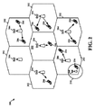
[0039]図3Aは、MBSFNにおけるエボルブドMBMS(eMBMS)チャネル構成の例を例示する図350である。セル352’内のeNB352は、第1のMBSFNエリアを形成し得、セル354’内のeNB354は、第2のMBSFNエリアを形成し得る。eNB352、354は各々、たとえば、合計8つのMBSFNエリアまで、他のMBSFNエリアに関連付けられ得る。MBSFNエリア内のセルは、リザーブドセルに指定され得る。リザーブドセルは、マルチキャスト/ブロードキャストコンテンツを提供しないが、セル352’、354’に時間同期され、MBSFNエリアへの干渉を制限するために、MBSFNリソース上で制限された電力を有し得る。MBSFNエリア内の各eNBは、同調して、同じeMBMS制御情報およびデータを送信する。各エリアは、ブロードキャスト、マルチキャスト、およびユニキャストサービスをサポートし得る。ユニキャストサービスは、たとえば、音声呼のような、特定のユーザを対象としたサービスである。マルチキャストサービスは、たとえば、加入者ビデオサービスのような、ユーザのグループが受け得るサービスである。ブロードキャストサービスは、たとえば、ニュースブロードキャストのような、すべてのユーザが受け得るサービスである。図3Aを参照すると、第1のMBSFNエリアは、たとえば、UE370に特定のニュースブロードキャストを提供することで、第1のeMBMSブロードキャストサービスをサポートし得る。第2のMBSFNエリアは、たとえば、UE360に異なるニュースブロードキャストを提供することで、第2のeMBMSブロードキャストサービスをサポートし得る。各MBSFNエリアは、1つまたは複数の物理マルチキャストチャネル(PMCH)(たとえば、15個のPMCH)をサポートする。各PMCHは、マルチキャストチャネル(MCH)に対応する。各MCHは、複数(たとえば、29個)のマルチキャスト論理チャネルを多重化し得る。各MBSFNエリアは、1つのマルチキャスト制御チャネル(MCCH)を有し得る。このように、1つのMCHは、1つのMCCHおよび複数のマルチキャストトラフィックチャネル(MTCH)を多重化し得、残りのMCHは、複数のMTCHを多重化し得る。
[0039] FIG. 3A is a diagram 350 illustrating an example of an evolved MBMS (eMBMS) channel configuration in MBSFN. An
[0040]UEは、eMBMSサービスアクセスの利用可能性および対応するアクセス層構成を発見するために、LTEセルにキャンプオン(camp on)し得る。最初に、UEは、システム情報ブロック(SIB)13(SIB13)を獲得し得る。続いて、SIB13に基づいて、UEは、MCCH上でMBSFNエリア構成メッセージを獲得し得る。続いて、MBSFNエリア構成メッセージに基づいて、UEは、MCHスケジューリング情報(MSI)MAC制御要素を獲得し得る。SIB13は、(1)セルによってサポートされる各MBSFNエリアのMBSFNエリア識別子、(2)MCCH繰り返し期間(period)(たとえば、32、64、…、256個のフレーム)、MCCHオフセット(たとえば、0、1、…、10個のフレーム)、MCCH修正期間(たとえば、512、1024個のフレーム)、シグナリング変調およびコーディングスキーム(MCS)、繰り返し期間およびオフセットによって示されるような無線フレームのどのサブフレームがMCCHを送信することができるかを示すサブフレーム割振り情報のようなMCCHを獲得するための情報、および(3)MCCH変更通知構成を含み得る。MBSFNエリアごとに1つのMBSFNエリア構成メッセージが存在する。MBSFNエリア構成メッセージは、(1)PMCH内の論理チャネル識別子によって識別される各MTCHの一時的モバイルグループ識別情報(TMGI)およびオプションのセッション識別子、(2)MBSFNエリアの各PMCHを送信するための割り振られたリソース(すなわち、無線フレームおよびサブフレーム)およびこのエリアにおけるすべてのPMCHのための割り振られたリソースの割振り期間(たとえば、4、8、…、256個のフレーム)、および(3)MSI MAC制御要素が送信されるMCHスケジューリング期間(MSP)(たとえば、8、16、32、…、または1024個の無線フレーム)を示し得る。 [0040] The UE may camp on the LTE cell to discover eMBMS service access availability and corresponding access layer configuration. Initially, the UE may obtain a system information block (SIB) 13 (SIB13). Subsequently, based on SIB13, the UE may acquire an MBSFN area configuration message on the MCCH. Subsequently, based on the MBSFN area configuration message, the UE may obtain an MCH scheduling information (MSI) MAC control element. The SIB 13 includes (1) the MBSFN area identifier of each MBSFN area supported by the cell, (2) the MCCH repetition period (eg, 32, 64,..., 256 frames), MCCH offset (eg, 0, 1, ... 10 frames), MCCH modification period (eg, 512, 1024 frames), signaling modulation and coding scheme (MCS), repetition period and which subframe of a radio frame as indicated by an offset Information for acquiring the MCCH, such as subframe allocation information indicating whether it can be transmitted, and (3) an MCCH change notification configuration. There is one MBSFN area configuration message for each MBSFN area. The MBSFN area configuration message includes (1) a temporary mobile group identification information (TMGI) and an optional session identifier for each MTCH identified by a logical channel identifier in the PMCH, and (2) for transmitting each PMCH in the MBSFN area. Allocated resources (ie, radio frames and subframes) and allocated resource allocation period for all PMCHs in this area (eg, 4, 8,..., 256 frames), and (3) MSI It may indicate the MCH scheduling period (MSP) (eg, 8, 16, 32, ..., or 1024 radio frames) over which the MAC control element is transmitted.
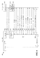
[0041]図3Bは、MSI MAC制御要素のフォーマットを例示する図390である。MSI MAC制御要素は、1つのMSPにつき一度送られ得る。MSI MAC制御要素は、PMCHの各スケジューリング期間の第1のサブフレームにおいて送られ得る。MSI MAC制御要素は、PMCH内の各MTCHの停止フレームおよびサブフレームを示し得る。MBSFNエリアあたり1つのPMCHにつき1つのMSIが存在し得る。 [0041] FIG. 3B is a diagram 390 illustrating the format of the MSI MAC control element. The MSI MAC control element can be sent once per MSP. The MSI MAC control element may be sent in the first subframe of each scheduling period of the PMCH. The MSI MAC control element may indicate a stop frame and subframe for each MTCH in the PMCH. There may be one MSI per PMCH per MBSFN area.
[0042]室外ユニット(ODU)およびゲートウェイは、たとえば、イーサネットまたはワイヤレスローカルエリアネットワーク(WLAN)のようなローカルエリアネットワークを介して、WWANネットワークからゲートウェイに接続されているエンドノード/デバイスに、eMBMS、音声およびインターネット制御およびデータプレーン機能性を可能にするために展開され得る。ODUは、WWANとの接続を確立し、エンドノードへの配信のためにデータをゲートウェイに配信し得る。本開示では、ODUという用語は、ディッシュアンテナおよび関連構成要素(たとえば、受信機および送信機)のような、室外に設置され得るデバイスを指し得る。しかしながら、ODUという用語は、室内アンテナおよび関連構成要素(たとえば、受信機および送信機)のような、室内に設置され得るデバイスも指し得る。ODUは、ブリッジモードまたはルータモードで動作するように構成され得る。ODUおよびゲートウェイは、互いの存在を発見し、セキュア接続を確立し、セキュア接続のステータスをモニタし、リンク失敗を検出し、リンク失敗から回復し得る。図4は、本開示の様々な態様に係る、例となるネットワーク400を例示する図である。図4は、BS402と、室外ユニット(ODU)404と、インターフェース406と、ゲートウェイ408と、UE412および413とを含む。ODU404は、BS402と通信リンク414を確立し得、通信リンク414上でBS402に通信を送り得るおよびそれから通信を受信し得る。たとえば、通信リンク414は、LTEのようなWAN無線アクセス技術(RAT)を使用して確立され得る。ある態様では、BS402は、WANプロトコルを使用して通信リンク414上で、eMBMSトラフィック、IPマルチメディアサブシステム(IMS)トラフィック、および/またはインターネットトラフィックを送信および受信するように構成され得る。BS402は、図1のeノードB106または図2のeNB204であり得る。
[0042] An outdoor unit (ODU) and a gateway can send eMBMS, e.g., to an end node / device connected to the gateway from the WWAN network via a local area network such as an Ethernet or wireless local area network (WLAN). Can be deployed to enable voice and internet control and data plane functionality. The ODU may establish a connection with the WWAN and deliver data to the gateway for delivery to the end node. In the present disclosure, the term ODU may refer to devices that can be installed outdoors, such as dish antennas and related components (eg, receivers and transmitters). However, the term ODU may also refer to devices that can be installed indoors, such as indoor antennas and related components (eg, receivers and transmitters). The ODU may be configured to operate in bridge mode or router mode. The ODU and gateway can discover each other's presence, establish a secure connection, monitor the status of the secure connection, detect link failure, and recover from link failure. FIG. 4 is a diagram illustrating an
[0043]図4に示されるように、ODU404は、インターフェース406を通してゲートウェイ408に結合される。ある態様では、インターフェース406は、ODU404に内蔵されるように構成され得る。たとえば、インターフェース406は、USB−イーサネットインターフェース(USB to Ethernet(登録商標)interface)であり得る。そのような例では、ODU404は、USBプロトコルを使用してデータ経路416上でゲートウェイ408に通信を送り得るおよびそれから通信を受信し得る。ゲートウェイ408は、イーサネットプロトコルを使用して、データ経路418上でODU404に通信を送り得るおよびそれから通信を受信し得る。たとえば、データ経路416は、USBケーブルであり得、データ経路418は、イーサネットケーブルであり得る。図4に示されるように、ゲートウェイ408は、UE412、413のような1つまたは複数のUEとの通信を可能にするように構成されたローカルネットワークモジュール410を含む。ある態様では、ゲートウェイ408は、ホームゲートウェイであり得る。たとえば、ゲートウェイ408は、ワイヤードおよび/またはワイヤレスルータ(たとえば、WiFi(登録商標)ルータ)として実現され得る。たとえば、ローカルネットワークモジュール410は、WLANプロトコルおよび/またはワイヤードイーサネットプロトコルを使用してUE412、413と通信するように構成され得る。したがって、そのような例では、通信リンク420、422は、ワイヤレスWLAN通信リンクまたはワイヤードイーサネット通信リンクであり得る。
[0043] As shown in FIG. 4,
[0044]UE412、413は、様々なタイプのデータトラフィックを処理するための1つまたは複数のアプリケーションで構成され得る。たとえば、UE412、413は、eMBMSデータを処理するためのeMBMSアプリケーションと、インターネットデータを処理するためのインターネットアプリケーションと、IMSデータを処理するためのIMSアプリケーションとを含み得る。ある態様では、ネットワーク400内のUE(たとえば、UE412)において動作するeMBMSアプリケーションは、eMBMSサービス(たとえば、コンテンツ)を要求するクエリをゲートウェイ408に送り得る。eMBMSサービスは、BS402からのeMBMSブロードキャストにおいて利用可能であり得る。たとえば、ゲートウェイ408において動作しているeMBMSサービスモジュール(ミドルウェアとも呼ばれる)は、イーサネットプロトコルを使用してデータ経路418上でODU404にこのクエリを転送し得る。クエリは、インターフェース406によって受信され得、USBプロトコルを使用してデータ経路416上でODU404に提供される。次に、ODU404は、WANプロトコルを使用して、BS402から、要求されたeMBMSサービスを搬送するeMBMSデータパケットを受信し得、データパケットをゲートウェイ408にルーティングし得る。次に、ゲートウェイ408は、WLANプロトコルまたはワイヤードイーサネットプロトコルを使用して、ローカルネットワークモジュール410を介して要求側のUE(たとえば、UE412)にeMBMSデータパケットを送り得る。
[0044] The
[0045]図5は、本開示の様々な態様に係る、ネットワークアーキテクチャ500を例示する図である。図5に示されるように、ネットワークアーキテクチャ500は、ODU501と、BS503と、ゲートウェイ506と、インターフェース510と、1つまたは複数のUE(たとえば、UE512、514)とを含む。たとえば、図5のODU501、BS503、ゲートウェイ506、インターフェース510、および1つまたは複数のUE512、514は、それぞれ、図4のODU404、BS402、ゲートウェイ408、インターフェース406、および1つまたは複数のUE412、413に対応し得る。図5に示されるように、ODU501は、モデム504と、中央処理装置(CPU)502と、インターネットプロトコルアドレス(IPA)モジュール508とを含む。ある態様では、モデム504は、1つまたは複数のアンテナと、トランシーバと、WANリンク505を通してBS503からワイヤレスWAN信号(たとえば、LTE信号)を受信するための他の適切な構成要素とを含み得る。CPU502は、ODU制御モジュール516と、相手先商標製品製造(OEM)アプリケーションモジュール518と、動的ホスト構成プロトコル(DHCP)サーバモジュール520と、ウェブサーバモジュール522と、カーネルモジュール524と、IPAドライバモジュール528とを含む。ある態様では、カーネルモジュール524は、追加のネットワークセキュリティのために、ルーティング、ネットワークアドレス変換、アプリケーションレイヤゲートウェイ(ALG)、ファイアウォール、ポート転送、および/または、DMZ(demilitarized zone)(境界ネットワークとも呼ばれる)の実現のような様々な機能を実行し得る。たとえば、DMZは、プライベートLANネットワークのホストが、外部ネットワークにアクセスすることができる一方で、外部ネットワークデバイスがプライベートLANネットワークに直接アクセスするのを阻み得る。IPAモジュール508は、フィルタモジュール530と、ルータモジュール532と、ネットワークアドレス変換(NAT)モジュール534と、ヘッダ制御モジュール536とを含む。ゲートウェイ506は、eMBMSサービスモジュール538(ミドルウェアモジュール538とも呼ばれる)と、カーネル/NATモジュール540と、イーサネット(Eth0)モジュール542と、ローカルネットワークモジュール544とを含む。
[0045] FIG. 5 is a diagram illustrating a
[0046]ある態様では、ODU501は、インターフェース510を通してゲートウェイ506に結合される。たとえば、インターフェース510は、USB−イーサネットインターフェースであり得る。別の例として、インターフェース510は、周辺構成要素相互接続エキスプレス(PCIe)−イーサネットインターフェース(Peripheral Component Interconnect Express (PCIe) to Ethernet interface)であり得る。そのような例では、ODU501は、USBプロトコルを使用してゲートウェイ506に通信を送り得るおよびそれから通信を受信し得る。ゲートウェイ506は、イーサネットプロトコルを使用して、ODU501に通信を送り得るおよびそれから通信を受信し得る。たとえば、ゲートウェイ506は、ODU制御フロー経路548に沿ってODU制御パケットを送り得るおよび/または受信し得る。たとえば、ODU制御パケットは、UE(たとえば、UE512)によって要求されるeMBMSサービスを示す1つまたは複数の制御メッセージを含み得る。ある態様では、制御メッセージは、クエリメッセージのようなeMBMS固有のメッセージであり得る。たとえば、クエリメッセージは、ネットワーク(たとえば、LTEネットワーク)がeMBMS対応であるかを決定するように、eMBMSサービスを可能にするように、および/またはチャネルをアクティブ化/非アクティブ化する(たとえば、一時的モバイルグループ識別情報(TMGI)のアクティブ化/非アクティブ化)ように、構成され得る。別の例として、ODU制御パケットは、後述するように、リンクステータスチェックメッセージであり得る。
[0046] In an aspect, the
[0047]図5の態様では、ODU501は、WANリンク505上で、UEによって要求されるeMBMSサービスのeMBMSデータパケット(eMBMS IPパケットとも呼ばれる)をBS503から受信し得る。ある態様では、eMBMS IPパケットは、標準IPパケットフォーマットを使用してカプセル化されるeMBMSデータであり得る。たとえば、BS503は、eMBMS IPパケットとしてeMBMSデータをカプセル化し得、ファイル配信オーバ単方向トランスポート(FLUTE)プロトコルを使用して、受信機と確立されたFLUTEセッション内に受信機にeMBMS IPパケットを配信し得る。一態様では、ゲートウェイ506は、ODU501を介してBS503とのFLUTEセッションをセットアップおよび制御し得る。そのような態様では、ゲートウェイ506は、ODU501を通してBS503からeMBMS IPパケットを受信し得る。
[0047] In the aspect of FIG. 5,
[0048]ODU501は、IPA508を使用して経路552および554に沿ってゲートウェイ506にeMBMS IPパケットをルーティングし得る。たとえば、eMBMS IPパケットは、IPv4またはIPv6 eMBMSパケットであり得る。たとえば、BS503から受信されるeMBMS IPパケットは、ODU501によって構成された1つまたは複数のフィルタ処理ルール(たとえば、レイヤ3フィルタ処理プロトコル)を適用し得るフィルタモジュール530に送られ得る。次に、eMBMS IPパケットは、eMBMS IPパケットにヘッダを追加(または、いくつかの態様では、ヘッダを除去)し得るヘッダ制御モジュール536に送られ得る。たとえば、ヘッダ制御モジュール530は、USBプロトコルを使用したeMBMS IPパケットの送信を可能にするために、eMBMS IPパケットにUSBプロトコルヘッダを追加し得る。
[0048]
[0049]図5にさらに示されるように、ODU501は、インターネット/IMS経路558に沿ってゲートウェイ506とインターネット/IMSパケットを通信し得る。たとえば、インターネット/IMSパケットは、ODU501とゲートウェイ506との間に確立されるIMS/インターネット呼のためのデータを搬送し得る。ある態様では、IPv4またはIPv6上のインターネット/IMS PDNトラフィックは、IPA508を使用してゲートウェイ506にルーティングされる。
[0049] As further shown in FIG. 5,
[0050]図5に示されるように、ゲートウェイ506は、UE512、514のような1つまたは複数のUEとの通信を可能にするように構成されたローカルネットワークモジュール544を含む。たとえば、ローカルネットワークモジュール544は、WLANプロトコルおよび/またはワイヤードイーサネットプロトコルを使用してUE512、514と通信するように構成され得る。したがって、そのような例では、通信リンク513、515は、WLAN通信リンクまたはワイヤードイーサネット通信リンクであり得る。UE512、514は、様々なタイプのデータトラフィックを処理するための1つまたは複数のアプリケーションで構成され得る。たとえば、UE512、514は、eMBMSデータを処理するためのeMBMSアプリケーション、インターネットデータを処理するためのインターネットアプリケーション、および/またはIMSデータを処理するためのIMSアプリケーションを含み得る。ある態様では、ゲートウェイ506は、イーサネットモジュール542において情報546を受信するように構成され得る。たとえば、情報546は、DHCPサーバモジュール520を介して受信されるプライベートIPv4アドレスであり得る。別の例では、情報546は、ネットワーク割当てIPv6プリフィックス(network assigned IPv6 prefix)であり得る。
[0050] As shown in FIG. 5, the
[0051]図5の態様では、ODU501は、ルータモードで動作するように構成される。ルータモードでは、パブリックIPアドレスは、ODU501に割り当てられ得、プライベートIPアドレスは、ゲートウェイ506に割り当てられ得る。たとえば、DHCPサーバモジュール520は、プライベートIPアドレス(たとえば、IPv4アドレス)をゲートウェイ506に割り当て得る。ある態様では、ゲートウェイ506は、DHCPサーバモジュール520を介してプライベートIPv4アドレスを獲得し得る。別の態様では、ゲートウェイ506は、ステートレスアドレス自動設定(SLAAC)を介して、ネットワークによって割り当てられたIPv6アドレスを獲得し得る。たとえば、IPv6アドレスは、地球規模で一意でありかつルーティング可能であり得る。ゲートウェイ506は、NATモジュール534によって実現されるNATファイアウォールの後ろで動作するように構成され得る。ある態様では、NATモジュール534は、インターネットパケット(たとえば、インターネットトラフィック)および/またはIMSパケット内の宛先アドレスをパブリックIPアドレスからプライベートIPアドレスに修正することで、このインターネットパケットおよび/またはIMSパケットに対してネットワークアドレス変換機能を実行し得る。DHCPオプション#120は、セッション開始プロトコル(SIP)呼を可能にするために、ネットワーク割当てIPv4/v6 P−CSCF(network assigned IPv4/v6 Proxy IMS call session control function)アドレスおよびFQDN(fully qualified domain name)リストをゲートウェイ506に送るためにODU501によってサポートされ得る。図5の構成では、ODU501上で動作するOEMアプリケーションが、ゲートウェイ506と共に、インターネット/IMS PDN呼データパイプを使用し得るように、PDN共有が許可される。上述したように、IPv4/v6上のeMBMS IPパケットおよび/またはIPv4/v6上のインターネット/IMS PDNトラフィックは、IPA508(IPAハードウェアオフロードエンジンとも呼ばれ得る)を使用してゲートウェイ506にルーティングされ得る。
[0051] In the aspect of FIG. 5,
[0052]図6は、ネットワークアーキテクチャ500のデータフロー600を例示する図である。図6では、ゲートウェイ506のeMBMSサービスモジュール538は、ODU制御モジュール516にマルチキャストメッセージ608(1つまたは複数のマルチキャストパケットとも呼ばれる)を送る。ある態様では、マルチキャストメッセージ608は、所定のUDPポートに送られ得る。ある態様では、マルチキャストメッセージ608は、所定の時間インターバルに基づいて周期的に送られ得る。たとえば、マルチキャストメッセージ608は、30秒ごとに1回送られ得る。ある態様では、ゲートウェイ506は、マルチキャストメッセージ608が送られるとタイマを開始(begin)し得る。そのような態様では、マルチキャストメッセージ608に対する応答(たとえば、応答メッセージ610)が受信されない場合、eMBMSサービスモジュール538は、マルチキャストメッセージ608を再送し得る。eMBMSサービスモジュール538は、応答が受信されるまでまたはタイマが満了になるまで、マルチキャストメッセージ608を再送し続け得る。応答を受信する前にタイマが満了になる場合、eMBMSサービスモジュール538は、ODU501が利用不可能であると決定し得、もはやマルチキャストメッセージ608を再送しないであろう。別の態様では、マルチキャストメッセージ608に対する応答(たとえば、応答メッセージ610)が受信されない場合、eMBMSサービスモジュール538は、マルチキャストメッセージ608を再送し得る。そのような態様では、eMBMSサービスモジュール538は、再送されるマルチキャストメッセージ608のカウントを維持し得る。eMBMSサービスモジュール538は、カウントが閾値に達するかまたは超えるまで、マルチキャストメッセージ608を再送し続け得る。カウントが閾値に達するかまたは超える場合、eMBMSサービスモジュール538は、ODU501が利用不可能であると決定し得、もはやマルチキャストメッセージ608を再送しないであろう。
[0052] FIG. 6 is a diagram illustrating a
[0053]たとえば、マルチキャストメッセージ608は、IPバージョン6(「IPv6」)通信プロトコルを使用して生成されるメッセージであり得る。たとえば、ゲートウェイ506のeMBMSサービスモジュール538は、ゲートウェイ506とODU501との間でIPv6ローカルリンクアドレスを使用してUDPパケットを生成することで、マルチキャストメッセージ608を生成し得る。たとえば、UDPパケットのコンテンツは、文字列(たとえば、一連の文字)であり得る。eMBMSサービスモジュール538は、UDPパケットを既知のUDPポートに送り得る。ODU501は、UDPパケットについてUDPポートをモニタするように構成され得、UDPポートにおいて受信されるUDPパケットがゲートウェイ506からのものであるとみなし得る。
[0053] For example,
[0054]図6の態様では、ODU501のIPアドレスは、ゲートウェイ506に知られていないであろう。そのような態様では、マルチキャストメッセージ608は、ゲートウェイ506が、ODU501のロケーション(たとえば、IPアドレス)および/または存在を発見することを可能にし得る。たとえば、ODU501は、ODUが、所定のUDPポート上でマルチキャストメッセージ608をリスンする待機モードにあるように構成され得る。ODU制御モジュール516においてマルチキャストメッセージ608を受信すると、ODU501は、もはや待機モードに留まらず、ゲートウェイ506に応答メッセージ610を送る。ある態様では、応答メッセージは、ユニキャストメッセージであり得る。ゲートウェイ506は、ユニキャスト応答メッセージ610のヘッダに含まれる送り側のIPアドレスを識別することでODU501のIPアドレスを決定し得る。
[0054] In the aspect of FIG. 6, the IP address of
[0055]ODU制御モジュール516は、612において、セキュア接続の確立を開始するTCP接続信号を待つ。ある態様では、TCP接続は、所定のTCPポート上で確立され得る。ゲートウェイ506が、ユニキャスト応答610を受信した後、ゲートウェイ506は、マルチキャストクライアントを停止し614、もはやマルチキャストメッセージ608を送らないであろう。ゲートウェイ506は、続いて、TCPクライアントを開始する616。ゲートウェイは、ODU501にTCP接続メッセージ618を送り、ODU501は、それに応じて、TCP受諾メッセージ620を送る。ゲートウェイ506が、TCP受諾メッセージ620を受信した後、ゲートウェイ506は、セキュアソケットレイヤ(SSL)クライアントハンドシェイクメッセージ622を送ることで、ODU501とのSSLハンドシェイクを開始する。ODU501は、それに応じて、SSLサーバハンドシェイクメッセージ624を送り、SSLハンドシェイクメッセージ626がそれに続く。ある態様では、SSLハンドシェイクメッセージ626は、証明書および鍵(たとえば、パブリックキー)を含み得る。ゲートウェイ506は、ゲートウェイ506がメッセージをハッシュおよび暗号化するために鍵を使用し始めるであろうことを示すために、その鍵と暗号変更通知とを含むSSLハンドシェイクメッセージ628を送る。したがって、図6に示されるように、セキュア接続(たとえば、SSL接続)629は、ゲートウェイ506とODU501との間で確立される。ゲートウェイ506は、セキュア接続上でODU501にハンドシェイク完了メッセージ630を送る。ODU501は、それに応じて、セキュア接続上でハンドシェイク暗号変更メッセージ632を送り、ハンドシェイク完了メッセージ634がそれに続く。
[0055] The
[0056]ゲートウェイ506は、ODU501がゲートウェイ506を認証することを可能にするゲートウェイ認証メッセージ636をセキュア接続上で送る。ODU501がゲートウェイ506を認証した後、ODU501は、ゲートウェイ506に、セキュア接続上で応答638を送る。次に、ゲートウェイ506およびODU501は、TCP/IPプロトコルを使用して、セキュア接続上でODU制御パケット640を交換し得、ODU制御516およびモデム504は、制御メッセージ642を交換し得る。
[0056] The
[0057]ある態様ではODU制御パケット640は、セキュア接続上でMBMSセッションを確立するためにゲートウェイ506によって送られ得る。ODU501は、制御パケットを復号し得、eMBMSセッションを確立するためにモデムサービスを開始し得る。たとえば、モデムサービスは、モデム504に制御メッセージ642を送るようにODU制御モジュール516を構成することで、開始され得る。ある態様では、MBMSセッションは、eMBMSセッションであり得る。
[0057] In an aspect, the
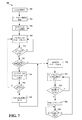
[0058]図7は、本開示の様々な態様に係る、ODU(たとえば、ODU501)のための方法のフローチャート700である。702において、ODUは、パワーオンされ、初期化プロシージャを実行する。704において、ODUは、イーサネット接続を検出する。たとえば、図5を参照すると、イーサネット接続は、インターフェース510とゲートウェイ506のイーサネット(Eth0)モジュール542との間のイーサネット接続であり得る。706において、ODUは、マルチキャストサーバを開始する。708において、ODUは、マルチキャストメッセージをリスンする。たとえば、マルチキャストメッセージは、UDPパケットであり得、ODUは、UDPパケットについて既知のUDPポートをモニタし得る。710において、ODUは、マルチキャストメッセージがゲートウェイから受信されるかどうかを決定する。たとえば、ODUは、既知のUDPポートにおいて受信されるUDPパケットがゲートウェイ506からのものであると決定し得る。別の例では、ODUは、マルチキャストメッセージのコンテンツ(たとえば、文字列)を、ゲートウェイからのものであると識別し得る。ゲートウェイからのマルチキャストメッセージがいずれもODUによって受信されない場合、ODUは708に戻り、マルチキャストメッセージをリスンし続ける。そうではなく、マルチキャストメッセージがゲートウェイから受信される場合、712において、ODUは、ODUとゲートウェイとの間のTCP SSL接続がアクティブであるかどうかを決定する。
[0058] FIG. 7 is a
[0059]TCP SSL接続がアクティブである場合、714において、ODUは、ゲートウェイにリンクステータスチェックメッセージを送る。716において、ODUは、リンクステータスチェックメッセージに対する応答が受信されるかどうかを決定する。応答が受信される場合、ODUは、708に戻り、マルチキャストメッセージをリスンし続ける。そうではなく、いずれの応答も受信されない場合、718において、ODUは、TCP SSL接続を閉じる。次に、720において、ODUは、TCP接続の確立を開始するために、ゲートウェイにUDP応答メッセージを送る。 [0059] If the TCP SSL connection is active, at 714, the ODU sends a link status check message to the gateway. At 716, the ODU determines whether a response to the link status check message is received. If a response is received, the ODU returns to 708 and continues to listen for multicast messages. Otherwise, if no response is received, at 718 the ODU closes the TCP SSL connection. Next, at 720, the ODU sends a UDP response message to the gateway to begin establishing a TCP connection.
[0060]712において、TCP SSL接続(SSL接続とも呼ばれる)がアクティブでないとODUが決定する場合、720において、ODUは、ゲートウェイにUDP応答メッセージを送る。722において、ODUは、ゲートウェイからのTCP接続信号を待つ。TCP接続信号がゲートウェイからのものでない場合、ODUは722に戻り、セキュア接続の確立を開始するTCP接続信号を待ち続ける。そうではなく、TCP接続要求がゲートウェイからのものであり、かつ、TCP接続が確立される場合、ODUは、SSL接続を確立するために、726において、SSLハンドシェイクを実行する。たとえば、SSL接続を確立するために、ゲートウェイは、SSL_connectメッセージを送り得、ODUは、SSL_acceptメッセージを送り得る。その後、証明書(たとえば、X.509証明書)および1つまたは複数の鍵が、ゲートウェイとODUとの間で交換され得る。ODUは、証明書が存在するかどうかを決定し得、SSL接続を確立する前に、鍵を検証(validate)し得る。ある態様では、ODUは、SSL接続が成功裏に確立されるとき、ステートマシンのフラグを「真」に設定し得る。SSL接続が失敗する場合、ODUは、フラグを「偽」に設定することでステートマシン内のフラグをクリアし得る。したがって、ある態様では、712において、ODUは、ステートマシン内のフラグの状態を決定することで、TCP SSL接続がアクティブであるかどうかを決定し得る。たとえば、フラグが「真」に設定されているとODUが決定する場合、ODUは、SSL接続がアクティブであると決定し得る。 [0060] If, at 712, the ODU determines that the TCP SSL connection (also referred to as an SSL connection) is not active, at 720, the ODU sends a UDP response message to the gateway. At 722, the ODU waits for a TCP connection signal from the gateway. If the TCP connection signal is not from the gateway, the ODU returns to 722 and continues to wait for the TCP connection signal to initiate secure connection establishment. Otherwise, if the TCP connection request is from the gateway and a TCP connection is established, the ODU performs an SSL handshake at 726 to establish an SSL connection. For example, to establish an SSL connection, the gateway may send an SSL_connect message and the ODU may send an SSL_accept message. Thereafter, a certificate (eg, an X.509 certificate) and one or more keys may be exchanged between the gateway and the ODU. The ODU may determine whether a certificate exists and may validate the key before establishing an SSL connection. In one aspect, the ODU may set the state machine flag to “true” when the SSL connection is successfully established. If the SSL connection fails, the ODU may clear the flag in the state machine by setting the flag to “false”. Thus, in an aspect, at 712, the ODU may determine whether a TCP SSL connection is active by determining the state of a flag in the state machine. For example, if the ODU determines that the flag is set to “true”, the ODU may determine that the SSL connection is active.
[0061]728において、ODUは、SSL接続がアクティブであるかどうかを決定する。ある態様では、ODUは、先に述べたように、ステートマシン内のフラグの状態を決定することで、SSL接続がアクティブであるかどうかを決定し得る。たとえば、フラグが「真」に設定されているとODUが決定する場合、ODUは、SSL接続がアクティブであると決定し得る。SSL接続がアクティブである場合、ODUは728に戻り、SSL接続がアクティブであるかどうかを決定し続ける。そうではなく、728において、SSL接続がアクティブではないとODUが決定する場合、ODUは706に戻り、マルチキャストサーバを開始する。 [0061] At 728, the ODU determines whether the SSL connection is active. In an aspect, the ODU may determine whether the SSL connection is active by determining the state of the flag in the state machine, as described above. For example, if the ODU determines that the flag is set to “true”, the ODU may determine that the SSL connection is active. If the SSL connection is active, the ODU returns to 728 and continues to determine whether the SSL connection is active. Otherwise, at 728, if the ODU determines that the SSL connection is not active, the ODU returns to 706 and starts the multicast server.
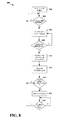
[0062]図8は、本開示の様々な態様に係る、ゲートウェイのための方法のフローチャート800である。802において、ゲートウェイは、パワーオンされ、初期化プロセスを経験する。804において、ゲートウェイは、イーサネット接続が利用可能かどうかを決定する。イーサネット接続が利用可能でない場合、ゲートウェイは、804に戻り、イーサネット接続が利用可能かどうか決定し続ける。そうではなく、イーサネット接続が利用可能であるとゲートウェイが決定する場合(804)、806において、ゲートウェイは、所定のUDPポートにマルチキャストメッセージを送る。808において、ゲートウェイは、UDP応答が受信されるかどうかを決定する。UDP応答が受信されないとゲートウェイが決定する場合(808)、ゲートウェイは806に戻り、1つまたは複数のマルチキャストメッセージを送り続ける。そうではなく、UDP応答がODUから受信されるとゲートウェイが決定する場合(808)、810において、ゲートウェイは、マルチキャストクライアントをシャットダウンし、もはやマルチキャストメッセージを送らない。812において、ゲートウェイは、TCP接続メッセージを送ることで、ODUとのTCP接続を開始する。814において、ゲートウェイは、TCP接続が確立されているかどうかを決定する。ある態様では、ゲートウェイは、ODUから特定のポートにおいて受信されるメッセージに基づいて、TCP接続が確立されると決定し得る。たとえば、メッセージは、TCP接続が成功したことを示し得る。TCP接続が確立されていない場合、ゲートウェイは、804に戻り、イーサネット接続が利用可能かどうかを決定する。そうではなく、TCP接続が確立されている場合、816において、ゲートウェイは、セキュア接続を確立するために、ODUとSSLハンドシェイクを実行する。818において、ゲートウェイは、SSL接続がアクティブであるかどうかを決定する。たとえば、SSL接続を確立するために、ゲートウェイは、SSL_connectメッセージを送り得、ODUは、SSL_acceptメッセージを送り得る。その後、証明書(たとえば、X.509証明書)および1つまたは複数の鍵が、ゲートウェイとODUとの間で交換され得る。ODUは、証明書が存在するかどうかを決定し得、SSL接続を確立する前に、鍵を検証し得る。そうではなく、鍵が検証されることができない場合、ODUは、ゲートウェイにエラーを返し得る。ある態様では、ゲートウェイは、SSL接続が成功裏に確立されるとき、ステートマシンのフラグを「真」に設定し得る。SSL接続が失敗する場合、ゲートウェイは、フラグを「偽」に設定することでステートマシン内のフラグをクリアし得る。したがって、ゲートウェイは、ステートマシン内のフラグの状態を決定することで、SSL接続がアクティブであるかどうかを決定し得る。たとえば、フラグが「真」に設定されているとゲートウェイが決定する場合、ゲートウェイは、SSL接続がアクティブであると決定し得る。
[0062] FIG. 8 is a
[0063]SSL接続がアクティブである場合、ゲートウェイは818に戻り、SSL接続がアクティブであるかどうかを決定する。そうではなく、SSL接続がアクティブでないとゲートウェイが決定する場合(818)、ゲートウェイは、804に戻り、イーサネット接続が利用可能であるかどうかを決定する。 [0063] If the SSL connection is active, the gateway returns to 818 to determine if the SSL connection is active. Otherwise, if the gateway determines that the SSL connection is not active (818), the gateway returns to 804 to determine if an Ethernet connection is available.
[0064]1つのシナリオでは、TCP接続(たとえば、SSL接続)上で確立されたゲートウェイ506からODU501へのエンド・ツー・エンドリンクは、1つまたは複数の原因により失敗し得る。1つの例となるシナリオでは、エンド・ツー・エンドリンクは、ゲートウェイ506において動作するeMBMSアプリケーションのエラーまたは異常(malfunction)により失敗し得る。そのようなシナリオでは、ODU501は、ゲートウェイ506にeMBMSデータパケットを送り続けることで不必要に電力を消費し得、ここで、ゲートウェイ506において動作するeMBMSアプリケーションは失敗しており、もはやODU501からのeMBMSパケットを処理することはできない。別の例となるシナリオでは、TCP接続(たとえば、SSL接続)上で確立されたODU501からゲートウェイ506へのエンド・ツー・エンドリンクは、1つまたは複数の原因により失敗し得る。たとえば、エンド・ツー・エンドリンクは、ODU501の制御プレーンのエラーまたは異常により失敗し得る。そのようなシナリオでは、TCP接続が終了され、ODU501がエラーまたは異常から回復した後に、再確立されるべきである。上述した例となるシナリオでは、TCP接続を自動的に終了するように設定されたTCP接続タイムアウトはゆっくりであり得る。結果として、TCP接続が再確立され得る前に、大きな遅延が存在し得る。そのような遅延は、TCP接続が再確立される前のeMBMSサービスの受信を阻み得るため、ユーザ経験を劣化させ得る。
[0064] In one scenario, an end-to-end link from the
[0065]ある態様では、ODU501および/またはゲートウェイ506は、ODU501とゲートウェイ506との間のTCP接続(たとえば、SSL接続)上で通信されるリンクステータスチェックメッセージ(いくつかの態様では「ハートビートパケット」とも呼ばれる)の使用を通してエンド・ツー・エンドリンクが失敗したかどうかを決定し得る。たとえば、リンクステータスチェックメッセージは、メッセージが送られる時間のような、情報の1つまたは複数の項目を含むメッセージであり得る。リンクステータスチェックメッセージの受信機(たとえば、ゲートウェイ506)は、リンクステータスチェックメッセージに含まれる情報の1つまたは複数の項目を含むメッセージで応答し得る。ある態様では、応答が閾値時間期間内にリンクステータスチェックメッセージの送り側(たとえば、ODU501)によって受信されない場合、送り側は、エンド・ツー・エンドリンクが失敗したとみなす。そのような態様では、リンクステータスチェックメッセージの送り側は、すべてのeMBMS/IMS/インターネットリソースをリリースし得、続いてTCP接続を終了および再確立し得る。ある態様では、ODU501が、ODU501とゲートウェイ506との間のエンド・ツー・エンドリンクの失敗を検出するとき、ODU501は、初期化状態に戻り、所定のUDPポート上でマルチキャストメッセージをリスンする。ODU501がゲートウェイ506から新しいマルチキャストメッセージを受信するとき、ODU501は、ユニキャスト応答メッセージで、このマルチキャストメッセージに対して応答し得る。ユニキャスト応答メッセージは、ゲートウェイ506に、新しいTCP接続確立プロシージャを開始させ得る。ある態様では、ゲートウェイ506が、ODU501とゲートウェイ506との間のエンド・ツー・エンドリンクの失敗を検出するとき、ゲートウェイ506は、初期化状態に戻り、所定のUDPポートにマルチキャストメッセージを送ることでODU501を発見しようと試みる。
[0065] In an aspect, the
[0066]図9は、本開示の様々な態様に係る、ODUとゲートウェイとの間のメッセージフローを例示する図である。図9では、ODU501およびゲートウェイ506は、セキュア接続(たとえば、SSL接続)906を確立する。図9に示されるように、ゲートウェイ506は、ODU501へのイーサネット接続が利用可能でない(失敗した)と決定し(908)、その結果、セキュア接続906がもはや利用可能ではないと決定する。続いて、ゲートウェイ506は、ODU501へのイーサネット接続が利用可能であると決定し(910)、ゲートウェイ506は、マルチキャストクライアントを開始する(912)。ゲートウェイ506は、ODU501にマルチキャストメッセージ914を送る。ODU501は、ゲートウェイからのマルチキャストメッセージが受信されるとき、ゲートウェイ506にユニキャストメッセージ920を送る。次に、ODU501は、TCP接続の確立を開始するためにTCP信号を待つ(922)。ゲートウェイ506が、ユニキャストメッセージ920を受信するとき、ゲートウェイ506は、マルチキャストクライアントを停止し(924)、もはやマルチキャストメッセージを送らないであろう。ゲートウェイ506は、続いて、TCPクライアントを開始する(926)。ゲートウェイは、ODU501にTCP接続メッセージ928を送り、それに応じて、ODU501は、TCP受諾メッセージ930を送る。ゲートウェイ506が、TCP受諾メッセージ930を受信した後、ゲートウェイ506は、セキュアソケットレイヤ(SSL)クライアントハンドシェイクメッセージ932を送ることでODU501とのSSLハンドシェイクを開始する。ODU501は、それに応じて、SSLサーバハンドシェイクメッセージ934を送り、鍵を含む証明書を含んだSSLハンドシェイクメッセージ936がそれに続く。ゲートウェイ506は、ゲートウェイ506がメッセージをハッシュおよび暗号化するために鍵を使用し始めるであろうことを示すために、その鍵と暗号変更通知とを含むSSLハンドシェイクメッセージ938をODUに送る。したがって、図9に示されるように、セキュア接続(たとえば、SSL接続)939は、ゲートウェイ506とODU501との間で確立される。ゲートウェイ506は、セキュア接続上でODU501にハンドシェイク完了メッセージ940を送る。ODU501は、それに応じて、セキュア接続上でハンドシェイク暗号変更メッセージ942を送り、ハンドシェイク完了メッセージ934がそれに続く。
[0066] FIG. 9 is a diagram illustrating a message flow between an ODU and a gateway according to various aspects of the disclosure. In FIG. 9,
[0067]ある態様では、ゲートウェイ506は、セキュア接続上でゲートウェイ認証メッセージを送り得、これは、ODU501がゲートウェイ506を認証することを可能にする。ODU501がゲートウェイ506を認証した後、ODU501は、ゲートウェイ506に、セキュア接続上で応答を送り得る。次に、ゲートウェイ506およびODU501は、TCP/IPプロトコルを使用して、セキュア接続上でODU制御パケットを交換し得る。そのような態様では、ODU制御パケットは、セキュア接続上でeMBMSセッションを確立するためにゲートウェイ506によって送られ得る。ODU501は、制御パケットを復号し得、対象のサービスのためにeMBMSセッションを確立するよう求める要求をモデムに送り得る。
[0067] In an aspect, the
[0068]図10は、本開示の様々な態様に係る、ODUとゲートウェイとの間のメッセージフローを例示する図である。図10では、ODU501およびゲートウェイ506が、セキュア接続(たとえば、SSL接続)1005を確立する。図10に示されるように、ODU501は、ゲートウェイ506へのイーサネット接続が失敗したと決定し(1006)、その結果、セキュア接続1005は、もはや利用可能ではない。続いて、ODU501は、プロセス間通信1008を受信する。ゲートウェイ506は、プロセス間通信1008に対するいずれの応答も、プロセス間通信1008を送ってから閾値時間期間内に受信されていないと決定し、タイムアウト1010を経験する。次に、ゲートウェイ506は、ODU501を発見するためおよびセキュア接続を再確立するために、マルチキャストメッセージ1014を送るためのマルチキャストクライアント1012を開始する。
[0068] FIG. 10 is a diagram illustrating a message flow between an ODU and a gateway according to various aspects of the disclosure. In FIG. 10,
[0069]図11は、本開示の様々な態様に係る、ネットワークアーキテクチャ1100を例示する図である。図11に示されるように、ネットワークアーキテクチャ1100は、ODU1101と、BS1103と、ゲートウェイ1106と、インターフェース1110と、1つまたは複数のUE(たとえば、UE1112、1114)とを含む。たとえば、図11のODU1101、BS1103、ゲートウェイ1106、インターフェース1110、および1つまたは複数のUE1112、1114は、それぞれ、図4のODU404、BS402、ゲートウェイ408、インターフェース406、および1つまたは複数のUE412、413に対応し得る。図11に示されるように、ODU1101は、モデム1104と、CPU1102と、IPAモジュール1108とを含む。CPU1102は、ODU制御モジュール1116と、OEMアプリケーションモジュール1118と、カーネルモジュール1120と、IPAドライバモジュール1124とを含む。ある態様では、モデム1104は、1つまたは複数のアンテナと、トランシーバと、WANリンク1105を通してBS1103からワイヤレスWAN信号(たとえば、LTE信号)を受信するための他の適切な構成要素とを含み得る。
[0069] FIG. 11 is a diagram illustrating a
[0070]ある態様では、カーネルモジュール1120は、ALGのような様々な機能を実行し得る。IPAモジュール1108は、フィルタモジュール1126と、ヘッダ制御モジュール1130とを含む。ゲートウェイ1106は、eMBMSサービスモジュール1132(ミドルウェアモジュール1132とも呼ばれる)と、カーネル/NATモジュール1134と、イーサネット(Eth0)モジュール1136と、ローカルネットワークモジュール1138とを含む。
[0070] In an aspect, the kernel module 1120 may perform various functions such as ALG. The
[0071]ある態様では、ODU1101は、インターフェース1110を通してゲートウェイ1106に結合される。たとえば、インターフェース1110は、USB−イーサネットインターフェースであり得る。そのような例では、ODU1101は、USBプロトコルを使用して、ゲートウェイ1106に通信を送り得るおよびそれから通信を受信し得る。ゲートウェイ1106は、イーサネットプロトコルを使用して、ODU1101に通信を送り得るおよびそれから通信を受信し得る。たとえば、ゲートウェイ1106は、ODU制御フロー経路1142に沿ってODU制御パケットを送り得るおよび/または受信し得る。ODUパケットは、ODU制御フロー経路1144を介してモデム1104によって受信され得る。たとえば、ODU制御パケットは、UE(たとえば、UE1112)によって要求されるeMBMSサービスを示す情報を含み得る。別の例として、ODU制御パケットは、先に述べたように、リンクステータスチェックメッセージであり得る。
[0071] In an aspect, the
[0072]図11の態様では、ODU1101は、WANリンク1105上でUEによって要求されるeMBMSサービスのeMBMS IPパケットをBS1103から受信し得る。ODU1101は、IPA1108を使用してeMBMS IP経路1146および1150に沿ってゲートウェイ1106にeMBMS IPパケットを配信するためのブリッジとして機能し得る。たとえば、eMBMS IPパケットは、IPv4またはIPv6のeMBMSパケットであり得る。たとえば、eMBMS IP経路1146を介してBS1103から受信されるeMBMS IPパケットは、ODU1101によって構成された1つまたは複数のフィルタ処理規則(たとえば、レイヤ3フィルタ処理プロトコル)を適用し得るフィルタモジュール1126に送られ得る。次に、eMBMS IPパケットは、eMBMS IPパケットにヘッダを追加(または、いくつかの態様では、ヘッダを除去)し得るヘッダ制御モジュール1130に送られ得る。たとえば、ヘッダ制御モジュール1130は、USBプロトコルを使用したeMBMS IPパケットの送信を可能にするために、eMBMS IPパケットにUSBプロトコルヘッダを追加し得る。
[0072] In the aspect of FIG. 11, the
[0073]図11にさらに示されるように、ODU1101は、インターネット/IMS経路1154に沿って、ゲートウェイ1106とインターネット/IMSパケットを通信し得る。たとえば、インターネット/IMSパケットは、ODU1101とゲートウェイ1106との間に確立されたIMS/インターネット呼についてのデータを搬送し得る。ある態様では、IPv4またはIPv6上のインターネット/IMS PDNトラフィックは、IPA1108を使用してゲートウェイ1106にブリッジされる。
[0073] As further shown in FIG. 11, ODU 1101 may communicate Internet / IMS packets with
[0074]図11に示されるように、ゲートウェイ1106は、UE1112、1114のような1つまたは複数のUEとの通信を可能にするように構成されたローカルネットワークモジュール1138を含む。たとえば、ローカルネットワークモジュール1138は、WLANプロトコルおよび/またはワイヤードイーサネットプロトコルを使用してUE1112、1114と通信するように構成され得る。したがって、そのような例では、通信リンク1113、1115は、WLAN通信リンクまたはワイヤードイーサネット通信リンクであり得る。UE1112、1114は、様々なタイプのデータトラフィックを処理するための1つまたは複数のアプリケーションで構成され得る。たとえば、UE1112、1114は、eMBMSデータトラフィックを処理するためのeMBMSアプリケーション、インターネットデータトラフィックを処理するためのインターネットアプリケーション、および/またはIMSデータトラフィックを処理するためのIMSアプリケーションを含み得る。ある態様では、ゲートウェイ1106は、イーサネットモジュール1136において情報1140を受信するように構成され得る。たとえば、情報1140は、モデム1104内のDHCPサーバモジュール1107を介して受信されるWWANネットワーク割当てIPv4アドレスであり得る。別の例では、情報1140は、ネットワーク割当てIPv6プリフィックスであり得る。
[0074] As shown in FIG. 11, the
[0075]図11の態様では、ODU1101は、ブリッジモードで動作するように構成される。たとえば、ODU1101は、ルータを実現することなくおよびネットワークアドレス変換なしに、ゲートウェイ1106によってサービス提供されるローカルネットワークにWANネットワーク(たとえば、LTEネットワーク)を接続するためのブリッジとして機能し得る。ブリッジモードでは、パブリックIPアドレス(たとえば、IPv4アドレス)が、ODU1101に割り当てられ得る。たとえば、パブリックIPアドレスは、モデム1104内のDHCPサーバ1107を介してODU1101によって獲得され得る。ゲートウェイ1106は、ゲートウェイ1106がODU1101を発見し、ODU1101とTCP接続を確立した後に、DHCPサーバ1107からパブリックIPアドレスを獲得し得る。別の態様では、ゲートウェイ1106は、ネットワークによって割り当てられたIPv6プリフィックスをさらに獲得し得る。図11の構成がブリッジモードで動作するため、ODU1101によって受信されるeMBMS IPパケットがネットワーク変換なしにゲートウェイに転送され得ることに留意されたい。このように、ゲートウェイ1106は、NATファイアウォールの後ろで動作しない。DHCPオプション#120は、SIP呼を可能にするために、ゲートウェイ1106にネットワーク割当てIPv4/v6 P−CSCFアドレスおよびFQDNリストを送るためにODU1101によってサポートされ得る。PDN共有は、図11の構成では許可されない。このように、ODU1101のCPU1102上で稼働しているOEMアプリケーションは、インターネット/IMS PDNタイプではなく他のPDNタイプを使用し得る。IPv4/IPv6上のeMBMSパケットは、IPA1108(IPAハードウェアオフロードエンジンとも呼ばれる)を使用してゲートウェイ1106にルーティングされ得る。IPv4/IPv6上のインターネット/IMS PDNトラフィックは、IPA1108を使用してゲートウェイ1106にブリッジされ得る。
[0075] In the aspect of FIG. 11, the
[0076]ある態様では、ゲートウェイ(たとえば、ゲートウェイ506またはゲートウェイ1106)は、ODU(たとえば、ODU501またはODU1101)の動作モード(たとえば、ルータモードまたはブリッジモード)を構成し得る。たとえば、ゲートウェイは、ルータモードでまたはブリッジモードで動作するようODUに命令する構成ファイルを含むメッセージをODUに送り得る。次に、ODUは、再初期化し(リブート動作とも呼ばれる)、構成ファイルを読み取り、構成ファイルで示されているモードで(たとえば、ルータモードでまたはブリッジモードで)動作を開始する。
[0076] In an aspect, a gateway (eg,
[0077]したがって、本開示は、エンドノード(たとえば、ゲートウェイ)によるネットワークデバイス(たとえば、ODU)の発見メカニズムを含み、IP上である制御プレーンのためのセキュリティを含む。本開示は、ネットワークデバイスとエンドノードとの間でのリンクステータスチェックメッセージを使用した接続(たとえば、ネットワークデバイスとエンドノードとの間のエンド・ツー・エンドリンク)失敗検出をさらに含む。本開示は、ブリッジモードまたはルータモードで動作することができるネットワークデバイスをさらに含む。WANネットワークからのeMBMS/IMS/インターネットトラフィックは、イーサネットリンク上でエンドノードにブリッジまたはルーティングされる。エンドノードは、ネットワークデバイスのモード(たとえば、ブリッジモードまたはルータモード)について無知である。 [0077] Accordingly, the present disclosure includes a network device (eg, ODU) discovery mechanism by end nodes (eg, gateways) and includes security for the control plane over IP. The disclosure further includes connection (eg, end-to-end link between network device and end node) failure detection using a link status check message between the network device and the end node. The present disclosure further includes a network device that can operate in a bridge mode or a router mode. EMBMS / IMS / Internet traffic from the WAN network is bridged or routed to end nodes over Ethernet links. The end node is ignorant about the mode of the network device (eg, bridge mode or router mode).
[0078]図12Aおよび12Bは、通信の方法のフローチャート1200である。方法は、ゲートウェイ(たとえば、ゲートウェイ506)によって実行され得る。図12Aおよび12Bにおいて点線で表される動作がオプションの動作を表すことは理解されるべきである。1202において、ゲートウェイは、ネットワークデバイスに結合されたイーサネットインターフェースがアクティブであるかどうかを決定する。ある態様では、ネットワークデバイスは、基地局(たとえば、基地局503)から、MBMSデータ、インターネットトラフィック、および/またはIMSトラフィックを受信するように構成されたODU(たとえば、ODU501)であり得る。たとえば、図5を参照すると、ゲートウェイ506は、イーサネットモジュール542が、初期化されており、ODU501と通信する能力があるかどうかを決定し得る。
[0078] FIGS. 12A and 12B are a
[0079]1204において、ゲートウェイは、ネットワークデバイス(たとえば、基地局503)にマルチキャストメッセージを送り、ここで、ネットワークデバイスのIPアドレスは、ゲートウェイに未知である。ある態様では、ゲートウェイは、30秒ごとに1回マルチキャストメッセージを送ることでマルチキャストメッセージを周期的に送る。ある態様では、マルチキャストメッセージは、イーサネットインターフェースがアクティブであると決定されるとき、イーサネットインターフェースを通してネットワークデバイスに周期的に送られる。たとえば、図6を参照すると、ゲートウェイ506は、ODU501にマルチキャストメッセージ608を送ることができる。
[0079] At 1204, the gateway sends a multicast message to a network device (eg, base station 503), where the IP address of the network device is unknown to the gateway. In an aspect, the gateway periodically sends multicast messages by sending a multicast message once every 30 seconds. In certain aspects, multicast messages are periodically sent through the Ethernet interface to the network device when it is determined that the Ethernet interface is active. For example, referring to FIG. 6, the
[0080]1206において、ゲートウェイは、マルチキャストメッセージに応答して、第1の応答メッセージがネットワークデバイスから受信されるかどうかを決定する。1208において、ゲートウェイは、第1の応答メッセージがネットワークデバイスから受信されるとき、第1の応答メッセージからネットワークデバイスのIPアドレスを決定する。ある態様では、ゲートウェイは、第1の応答メッセージを識別し、この応答メッセージのヘッダからIPアドレスを獲得することでIPアドレスを決定する。1210において、ゲートウェイは、決定されたIPアドレスを使用して、ネットワークデバイスとセキュア接続を確立する。ある態様では、ゲートウェイは、ネットワークデバイスとTCP接続を確立し、このTCP接続を使用してSSL接続を確立することで、セキュア接続を確立する。たとえば、図6を参照すると、ゲートウェイ506は、ODU501とメッセージ618および620を交換することでTCP接続を確立し得る。ゲートウェイ506は、ODU501とメッセージ622、624、626、628、630、632、および634を交換することでSSL接続を確立し得る。
[0080] At 1206, in response to the multicast message, the gateway determines whether a first response message is received from the network device. At 1208, the gateway determines the IP address of the network device from the first response message when the first response message is received from the network device. In an aspect, the gateway determines the IP address by identifying the first response message and obtaining the IP address from the header of the response message. At 1210, the gateway establishes a secure connection with the network device using the determined IP address. In an aspect, the gateway establishes a secure connection by establishing a TCP connection with the network device and establishing an SSL connection using the TCP connection. For example, referring to FIG. 6,
[0081]1212において、ゲートウェイは、ネットワークデバイスによるゲートウェイの認証を可能にするために、セキュア接続を通してネットワークデバイスに認証情報を送る。たとえば、図6を参照すると、ゲートウェイ506は、ゲートウェイ認証メッセージ636を送り得る。1214において、ゲートウェイは、セキュア接続上でeMBMSセッションを確立するために、ネットワークデバイスに制御メッセージを送る。たとえば、図6を参照すると、ゲートウェイ506は、ODU501にODU制御パケット640を送り得る。
[0081] At 1212, the gateway sends authentication information to the network device over the secure connection to allow authentication of the gateway by the network device. For example, referring to FIG. 6, the
[0082]1216において、ゲートウェイは、セキュア接続を通してネットワークデバイスからeMBMSデータを受信する。1218において、ゲートウェイは、ローカルネットワーク接続を通して少なくとも1つUEにeMBMSデータを送る。ある態様では、ローカルネットワーク接続は、WLANまたはワイヤードイーサネット接続である。1220において、ゲートウェイは、ネットワークデバイスからインターネットトラフィックおよび/またはIMSトラフィックを受信し、ここで、インターネットトラフィックおよび/またはIMSトラフィックは、イーサネットインターフェースを通してセキュア接続上で受信されている。 [0082] At 1216, the gateway receives eMBMS data from the network device over a secure connection. At 1218, the gateway sends eMBMS data to the at least one UE through the local network connection. In certain aspects, the local network connection is a WLAN or a wired Ethernet connection. At 1220, the gateway receives Internet traffic and / or IMS traffic from the network device, wherein the Internet traffic and / or IMS traffic is received over the secure connection through the Ethernet interface.
[0083]1222において、ゲートウェイは、セキュア接続を通してネットワークデバイスにリンクステータスチェックメッセージを送る。1224において、ゲートウェイは、第2の応答メッセージが、閾値時間期間内に、リンクステータスチェックメッセージに応答してネットワークデバイスから受信されるかどうかを決定する。1226において、ゲートウェイは、第2の応答メッセージが閾値時間期間内に受信されないとき、セキュア接続を終了する。1228において、ゲートウェイは、第2の応答メッセージが閾値時間期間内に受信されないとき、ネットワークデバイスにマルチキャストメッセージを送る。ある態様では、リンクステータスチェックメッセージおよび/またはマルチキャストメッセージは、周期的に送られ得る。たとえば、リンクステータスチェックメッセージは、時間インターバルに基づいて周期的に送られ得る。 [0083] At 1222, the gateway sends a link status check message to the network device over the secure connection. At 1224, the gateway determines whether a second response message is received from the network device in response to the link status check message within a threshold time period. At 1226, the gateway terminates the secure connection when the second response message is not received within the threshold time period. At 1228, the gateway sends a multicast message to the network device when the second response message is not received within the threshold time period. In certain aspects, link status check messages and / or multicast messages may be sent periodically. For example, link status check messages may be sent periodically based on time intervals.
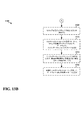
[0084]図13Aおよび13Bは、通信の方法のフローチャート1300である。方法は、ネットワークデバイス(たとえば、ODU501)によって実行され得る。図13Aおよび13Bにおいて点線で表される動作がオプションの動作を表すことは理解されるべきである。1302において、ODUは、ゲートウェイからのマルチキャストメッセージについて第1のポートをモニタする。ある態様では、モニタすることは、第1のポートを識別し、第1のポートにおいて受信されるべきマルチキャストメッセージを待つことで実行される。1304において、ODUは、マルチキャストメッセージが受信されるとき、ゲートウェイに応答メッセージを送る。1306において、ODUは、第2のポート上でセキュア接続の確立を開始するように構成された信号を受信する。ある態様では、第1のポートおよび第2のポートは、同じUDPポートであり得る。1308において、ODUは、ゲートウェイとセキュア接続を確立する。ある態様では、ODUは、ゲートウェイとTCP接続を確立し、このTCP接続を使用してSSL接続を確立することで、セキュア接続を確立する。1310において、ODUは、ゲートウェイから、ゲートウェイの認証を可能にするように構成された認証情報を受信する。1312において、ODUは、ゲートウェイから、セキュア接続上でのeMBMSセッションの確立を要求する制御メッセージを受信する。1314において、ODUは、セキュア接続を通してゲートウェイにeMBMSデータを送る。1316において、ODUは、ゲートウェイに、インターネットトラフィックまたはIMSトラフィックのうちの少なくとも1つを送る。ある態様では、インターネットトラフィックまたはIMSトラフィックのうちの少なくとも1つは、USB−イーサネットインターフェースを通してセキュア接続上で送られる。1318において、ODUは、ゲートウェイから、少なくとも1つの後続のマルチキャストメッセージを受信する。1320において、ODUは、セキュア接続がアクティブであるかどうかを決定する。1322において、ODUは、マルチキャストメッセージが受信され、かつ、セキュア接続がアクティブであるとき、ゲートウェイにリンクステータスチェックメッセージを送る。1324において、ODUは、リンクステータスチェックメッセージに対する応答が、閾値時間期間内に受信されない場合、セキュア接続を終了する。1326において、ODUは、少なくとも1つの後続のマルチキャストメッセージに応答して、ゲートウェイに第2の応答メッセージを送る。
[0084] FIGS. 13A and 13B are a
[0085]図14は、例示的な装置1402内の異なるモジュール/手段/構成要素間のデータフローを例示する概念的なデータフロー図1400である。装置は、ゲートウェイであり得る。装置は、インターフェース1408を通してODU1406(ネットワークデバイスとも呼ばれる)と通信するローカルネットワークモジュール1 1410を含む。ある態様では、ローカルネットワークモジュール1 1410は、イーサネットモジュールであり得、インターフェース1408は、USB−イーサネットインターフェースであり得る。そのような態様では、データ経路1432は、イーサネットケーブルとして実現され得、データ経路1430は、USBケーブルとして実現され得る。BS1404は、WANリンク1428(たとえば、LTE)を使用してODU1406と通信状態にあり得る。
[0085] FIG. 14 is a conceptual data flow diagram 1400 illustrating data flow between different modules / means / components in
[0086]装置は、データ1434を受信する受信モジュール1412をさらに含む。ある態様では、データ1434は、ネットワークデバイスから送られるインターネットトラフィック、IMSトラフィック、またはeMBMSデータであり得る。データ1434は、ローカルネットワークモジュール1 1410(たとえば、イーサネットモジュール)を通してセキュア接続上で受信され得る。
[0086] The apparatus further includes a
[0087]装置は、ネットワークデバイスとセキュア接続を確立する接続制御モジュール1414をさらに含む。接続制御モジュール1414は、ネットワークデバイスとTCPおよび/またはSSL接続を確立するとき、メッセージ1442(たとえば、TCP受諾および/またはSSLハンドシェイクメッセージ)を受信し得、メッセージ1450(たとえば、TCP接続および/またはSSLハンドシェイクメッセージ)を送り得る。
[0087] The apparatus further includes a
[0088]装置は、ネットワークデバイスに結合されたイーサネットモジュール(イーサネットインターフェースとも呼ばれる)がアクティブであるかどうかを決定する決定モジュール1416をさらに含む。たとえば、決定モジュール1416は、ローカルネットワークモジュール1 1410においてフラグ(たとえば、netif_carrier)のステータスをチェックすることで決定を行い得る。たとえば、フラグは、ローカルネットワークモジュール1 1410が、フラグが「真」に設定されているときにはアクティブであり、フラグが「偽」に設定されているときには非アクティブであることを示すように構成され得る。決定モジュール1416は、応答メッセージ1440が、マルチキャストメッセージに応じて、ネットワークデバイスから受信されるかどうかをさらに決定する。決定モジュール1416は、応答メッセージがネットワークデバイスから受信されるとき、応答メッセージ1440からネットワークデバイスのIPアドレスをさらに決定する。決定モジュール1416は、第2の応答メッセージ1441が、閾値時間期間内に、リンクステータスチェックメッセージに応答してネットワークデバイスから受信されるかどうかをさらに決定する。接続制御モジュール1414は、第2の応答メッセージが閾値時間期間内に受信されないときセキュア接続を終了する信号1439を受信する。
[0088] The apparatus further includes a
[0089]装置は、ネットワークデバイスにマルチキャストメッセージ1448を周期的に送るメッセージ送出モジュール1418をさらに含む。メッセージ送出モジュール1418は、決定モジュール1416からIPアドレス1446を受信する。メッセージ送出モジュール1418は、セキュア接続を通してネットワークデバイスにリンクステータスチェックメッセージ1449を周期的に送る。メッセージ送出モジュール1418は、第2の応答メッセージが閾値時間期間内に受信されないとき、ネットワークデバイスにマルチキャストメッセージを送る。
[0089] The apparatus further includes a
[0090]装置は、セキュア接続上でeMBMSセッションを確立するために、ネットワークデバイスに制御メッセージ1452を送るeMBMSサービスモジュール1420をさらに含む。eMBMSサービスモジュール1420は、eMBMSデータ1444を受信する。装置は、ローカルネットワーク接続1455を通して少なくとも1つのUE1426にeMBMSデータ1454を送るローカルネットワークモジュール2 1422をさらに含む。ある態様では、ローカルネットワーク接続1455は、WLANまたはワイヤードイーサネット接続である。装置は、ネットワークデバイスによるゲートウェイの認証を可能にするために、セキュア接続を通してネットワークデバイスにデータ経路1436上で認証情報を送る送信モジュール1424をさらに含む。
[0090] The apparatus further includes an
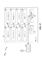
[0091]図15は、例示的な装置1502における異なるモジュール/手段/構成要素間のデータフローを例示する概念的なデータフロー図1500である。装置は、ネットワークデバイス(たとえば、ODU)であり得る。装置は、インターフェース1510を通してゲートウェイ(たとえば、ゲートウェイ1508)と通信する通信モジュール1512を含む。ある態様では、通信モジュール1512は、USBモジュールであり得、インターフェース1510は、USB−イーサネットインターフェースであり得る。そのような態様では、データ経路1532は、USBケーブルとして実現され得、データ経路1530は、イーサネットケーブルとして実現され得る。UE1506は、ローカルネットワーク接続1528(たとえば、WLANまたはワイヤードイーサネット)を使用してゲートウェイ1508と通信状態にあり得る。
[0091] FIG. 15 is a conceptual data flow diagram 1500 illustrating data flow between different modules / means / components in
[0092]装置は、ゲートウェイからのマルチキャストメッセージ1536について第1のポートをモニタするモニタリングモジュール1514をさらに含む。装置は、ゲートウェイからデータ経路1534を介して少なくとも1つの後続のマルチキャストメッセージを受信し、ゲートウェイからデータ経路1534を介してゲートウェイの認証を可能にするように構成された認証情報を受信し、および/または、ゲートウェイからデータ経路1534を介してセキュア接続上でのeMBMSセッションの確立を要求する制御メッセージを受信する受信モジュール1516をさらに含む。
[0092] The apparatus further includes a
[0093]装置は、セキュア接続がアクティブであるかどうかを決定する決定モジュール1518をさらに含む。決定モジュール1518は、データ経路1541を介して通信モジュール1512上のアクティビティを検査することで決定を行い得る。装置は、マルチキャストメッセージ1536が受信されるとき、ゲートウェイに第1の応答メッセージ1547を送り、および/または、マルチキャストメッセージ1536が受信され、かつ、セキュア接続がアクティブであるとき、ゲートウェイにリンクステータスチェックメッセージ1548を送るメッセージ送出モジュール1520をさらに含む。メッセージ送出モジュール1520は、決定モジュール1518から決定(たとえば、信号1546)を受信し得る。
[0093] The apparatus further includes a
[0094]装置は、第2のポート上でセキュア接続の確立を開始する信号を受信し、ゲートウェイとセキュア接続を確立し、および/または、リンクステータスチェックメッセージに対する応答が閾値時間期間内に受信されない場合にはセキュア接続を終了する接続制御モジュール1522をさらに含む。たとえば、接続制御モジュール1522は、ゲートウェイとTCPおよび/またはSSL接続を確立するとき、メッセージ1542(たとえば、TCP接続および/またはSSLハンドシェイクメッセージ)を受信し得、メッセージ1550(たとえば、TCP受諾および/またはSSLハンドシェイクメッセージ)を送り得る。接続制御モジュール1522は、決定モジュール1518から決定(たとえば、信号1542)を受信し得る。
[0094] The device receives a signal to initiate establishment of a secure connection on the second port, establishes a secure connection with the gateway, and / or a response to the link status check message is not received within a threshold time period In some cases, it further includes a
[0095]装置は、WANリンク1554(たとえば、LTE)上でWANプロトコルを使用してBS1504と通信するモデムモジュール1524をさらに含む。モデム1524は、制御情報1544を受信し得、ゲートウェイ1508にIPパケット1552(たとえば、eMBMSデータ)を送り得る。装置は、少なくとも1つの後続のマルチキャストメッセージに応答してゲートウェイ1508に第2の応答メッセージ1549を送り、セキュア接続を通してゲートウェイ1508にeMBMSデータを送り、および/または、インターフェース1510を通してセキュア接続上でゲートウェイ1508にインターネットトラフィックおよび/またはIMSトラフィックを送る送信モジュール1526をさらに含む。送信モジュールは、データ経路1538を通して通信モジュール1512への送信を提供する。
[0095] The apparatus further includes a
[0096]図16は、処理システム1614を用いる装置1402’のためのハードウェア実現の例を例示する図1600である。処理システム1614は、概してバス1624で表されるバスアーキテクチャを用いて実現され得る。バス1624は、処理システム1614の特定の用途と設計制約全体に依存して、任意の数の相互接続バスおよびブリッジを含み得る。バス1624は、プロセッサ1604、モジュール1410、1412、1414、1416、1414、1420、1422、1424およびコンピュータ読取可能な媒体/メモリ1606によって表される、1つまたは複数のプロセッサおよび/またはハードウェアモジュールを含む様々な回路を互いにリンクする。バス1624はまた、タイミングソース、周辺機器、電圧レギュレータ、および電力管理回路のような様々な他の回路をリンクすることができるが、これらは、当技術分野では周知であるため、これ以上説明されないであろう。
[0096] FIG. 16 is a drawing 1600 illustrating an example of a hardware implementation for an apparatus 1402 'using a
[0097]処理システム1614は、トランシーバ1610に結合され得る。トランシーバ1610は、1つまたは複数のアンテナ1620に結合される。トランシーバ1610は、伝送媒体上で様々な他の装置と通信するための手段を提供する。トランシーバ1610は、1つまたは複数のアンテナ1620から信号を受信し、受信された信号から情報を抽出し、抽出された情報を処理システム1614に、具体的には受信モジュール1412に、提供する。加えて、トランシーバ1610は、処理システム1614から、具体的には送信モジュール1424から、情報を受信し、その受信された情報に基づいて、1つまたは複数のアンテナ1620に適用されるべき信号を生成する。処理システム1614は、コンピュータ読取可能な媒体/メモリ1606に結合されたプロセッサ1604を含む。プロセッサ1604は、コンピュータ読取可能な媒体/メモリ1606に格納されたソフトウェアの実行を含む、汎用処理を担う。ソフトウェアは、プロセッサ1604によって実行されるとき、任意の特定の装置に関して先に述べた様々な機能を実行することを処理システム1614に行わせる。コンピュータ読取可能な媒体/メモリ1606はまた、ソフトウェアを実行するときにプロセッサ1604によって操作されるデータを格納するために使用され得る。処理システムはさらに、モジュール1410、1412、1414、1416、1418、1420、1422、および1424のうちの少なくとも1つを含む。モジュールは、プロセッサ1604において稼働しており、コンピュータ読取可能な媒体/メモリ1606に存在し/格納されたソフトウェアモジュール、プロセッサ1604に結合された1つまたは複数のハードウェアモジュール、またはそれらの何らかの組み合わせであり得る。
[0097]
[0098]一構成では、ワイヤレス通信のための装置1402/1402’は、基地局から、eMBMSデータ、インターネットトラフィック、および/またはIMSトラフィックを受信するように構成されたネットワークデバイスにマルチキャストメッセージを送るための手段と、ここで、ネットワークデバイスのIPアドレスは未知である、第1の応答メッセージが、マルチキャストメッセージに応答して、ネットワークデバイスから受信されるかどうかを決定するための手段と、第1の応答メッセージがネットワークデバイスから受信されるとき、第1の応答メッセージからネットワークデバイスのIPアドレスを決定するための手段と、決定されたIPアドレスを使用してネットワークデバイスとセキュア接続を確立するための手段と、セキュア接続を通してネットワークデバイスにリンクステータスチェックメッセージを送るための手段と、第2の応答メッセージが、閾値時間期間内に、リンクステータスチェックメッセージに応答して、ネットワークデバイスから受信されるかどうかを決定するための手段と、第2の応答メッセージが閾値時間期間内に受信されないとき、セキュア接続を終了するための手段と、第2の応答メッセージが閾値時間期間内に受信されないとき、ネットワークデバイスにマルチキャストメッセージを送るための手段と、ネットワークデバイスによるゲートウェイの認証を可能にするためにセキュア接続を通してネットワークデバイスに認証情報を送るための手段と、セキュア接続上でeMBMSセッションを確立するためにネットワークデバイスに制御メッセージを送るための手段と、セキュア接続を通してネットワークデバイスからeMBMSデータを受信するための手段と、ローカルネットワーク接続を通して少なくとも1つのUEにeMBMSデータを送るための手段と、イーサネットインターフェースを通してセキュア接続上でネットワークデバイスからインターネットトラフィックおよび/またはIMSトラフィックを受信するための手段と、ネットワークデバイスに結合されたイーサネットインターフェースがアクティブであるかどうかを決定するための手段とを含む。前述の手段は、前述の手段によって記載された機能を実行するように構成された、装置1402および/または装置1402’の処理システム1614の前述のモジュールのうちの1つまたは複数であり得る。
[0098] In one configuration, an apparatus for
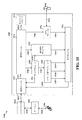
[0099]図17は、処理システム1714を用いる装置1502’のためのハードウェア実現の例を例示する図1700である。処理システム1714は、概してバス1724で表されるバスアーキテクチャを用いて実現され得る。バス1724は、処理システム1714の特定の用途と設計制約全体に依存して、任意の数の相互接続バスおよびブリッジを含み得る。バス1724は、プロセッサ1704、モジュール1512、1514、1516、1518、1520、1522、1524、1526およびコンピュータ読取可能な媒体/メモリ1706によって表される、1つまたは複数のプロセッサおよび/またはハードウェアモジュールを含む様々な回路を互いにリンクする。バス1724はまた、タイミングソース、周辺機器、電圧レギュレータ、および電力管理回路のような様々な他の回路をリンクすることができるが、これらは、当技術分野では周知であるため、これ以上説明されないであろう。
[0099] FIG. 17 is a drawing 1700 illustrating an example of a hardware implementation for an apparatus 1502 'using a
[00100]処理システム1714は、トランシーバ1710に結合され得る。トランシーバ1710は、1つまたは複数のアンテナ1720に結合される。トランシーバ1710は、伝送媒体上で様々な他の装置と通信するための手段を提供する。トランシーバ1710は、1つまたは複数のアンテナ1720から信号を受信し、受信された信号から情報を抽出し、抽出された情報を処理システム1714に、具体的には受信モジュール1516に、提供する。加えて、トランシーバ1710は、処理システム1714から、具体的には送信モジュール1526から情報を受信し、その受信された情報に基づいて、1つまたは複数のアンテナ1720に適用されるべき信号を生成する。処理システム1714は、コンピュータ読取可能な媒体/メモリ1706に結合されたプロセッサ1704を含む。プロセッサ1704は、コンピュータ読取可能な媒体/メモリ1706に格納されたソフトウェアの実行を含む、汎用処理を担う。ソフトウェアは、プロセッサ1704によって実行されるとき、任意の特定の装置に関して先に述べた様々な機能を実行することを処理システム1714に行わせる。コンピュータ読取可能な媒体/メモリ1706はまた、ソフトウェアを実行するときにプロセッサ1704によって操作されるデータを格納するために使用され得る。処理システムはさらに、モジュール1512、1514、1516、1518、1520、1522、1524、および1526のうちの少なくとも1つを含む。モジュールは、プロセッサ1704において稼働しており、コンピュータ読取可能な媒体/メモリ1706に存在し/格納されたソフトウェアモジュール、プロセッサ1704に結合された1つまたは複数のハードウェアモジュール、またはそれらの何らかの組み合わせであり得る。
[00100] The
[00101]一構成では、ワイヤレス通信のための装置1502/1502’は、ゲートウェイからのマルチキャストメッセージについて第1のポートをモニタするための手段と、マルチキャストメッセージが受信されるとき、ゲートウェイに応答メッセージを送るための手段と、第2のポート上でセキュア接続の確立を開始する信号を受信するための手段と、ゲートウェイとセキュア接続を確立するための手段と、ゲートウェイから少なくとも1つの後続のマルチキャストメッセージを受信するための手段と、セキュア接続がアクティブであるかどうかを決定するための手段と、マルチキャストメッセージが受信され、かつ、セキュア接続がアクティブであるとき、ゲートウェイにリンクステータスチェックメッセージを送るための手段と、リンクステータスチェックメッセージに対する応答が閾値時間期間内に受信されない場合、セキュア接続を終了するための手段と、少なくとも1つの後続のマルチキャストメッセージに応答して、ゲートウェイに第2の応答メッセージを送るための手段と、ゲートウェイから、ゲートウェイの認証を可能にするように構成された認証情報を受信するための手段と、ゲートウェイから、セキュア接続上でのeMBMSセッションの確立を要求する制御メッセージを受信するための手段と、セキュア接続を通してゲートウェイにeMBMSデータを送るための手段と、ゲートウェイにインターネットトラフィックまたはIMSトラフィックのうちの少なくとも1つを送るための手段と、ここで、インターネットトラフィックまたはIMSトラフィックのうちの少なくとも1つは、USB−イーサネットインターフェースを通してセキュア接続上で送られている、を含む。前述の手段は、前述の手段によって記載された機能を実行するように構成された、装置1502および/または装置1502’の処理システム1714の前述のモジュールのうちの1つまたは複数であり得る。
[00101] In one configuration, the device for
[00102]開示されたプロセス/フローチャートにおけるブロックの特定の順序または階層が例示的なアプローチの例示であることは理解される。設計の選好に基づいて、これらプロセス/フローチャートにおけるブロックの特定の順序または階層が再配列され得ることは理解される。さらに、いくつかのブロックは、組み合され得るまたは省略され得る。添付の方法の請求項は、様々なブロックの要素を1つのサンプルの順序で示しており、それらが提示された特定の順序または階層に限定されることは意味されない。 [00102] It is understood that the specific order or hierarchy of blocks in the disclosed processes / flowcharts is illustrative of an exemplary approach. It is understood that the specific order or hierarchy of blocks in these processes / flowcharts can be rearranged based on design preferences. In addition, some blocks may be combined or omitted. The accompanying method claims present elements of the various blocks in the order of a single sample and are not meant to be limited to the specific order or hierarchy presented.
[00103]先の説明は、当業者による、本明細書に説明された様々な態様の実施を可能にするために提供されている。これらの態様に対する様々な修正は、当業者には容易に明らかとなり、本明細書において定義された包括的な原理は、他の態様に適用され得る。ゆえに、特許請求の範囲は、本明細書で示された態様に限定されることが意図されたものではなく、特許請求の範囲における文言と合致する全範囲が付与されるべきであり、ここにおいて、単数形の要素への参照は、別途明記されていない限り、「1つ、および1つのみ」を意味すること意図されておらず、むしろ「1つまたは複数」を意味する。「例示的」という単語は、本明細書では、「実例、事例、または例示としての役割を果たす」を意味するために使用される。「例示的」として本明細書で説明された任意の態様は、必ずしも、他の態様よりも好ましいまたは有利であると解釈されるべきではない。別途明記されていない限り、「いくつかの」という用語は、1つまたは複数を指す。「A、B、またはCのうちの少なくとも1つ」、「A、B、およびCのうちの少なくとも1つ」、および「A、B、C、またはそれらの任意の組み合わせ」といった組み合わせは、A、B、および/またはCの任意の組み合わせを含み、Aの倍数、Bの倍数、またはCの倍数を含み得る。具体的には、「A、B、またはCのうちの少なくとも1つ」、「A、B、およびCのうちの少なくとも1つ」、および「A、B、C、またはそれらの任意の組み合わせ」といった組み合わせは、Aのみ、Bのみ、Cのみ、AとB、AとC、BとC、またはAとBとCであり得、ここで、任意のそのような組み合わせは、A、B、またはCの1つまたは複数のメンバを含み得る。当業者に知られているかかまたは後に知られることとなる、本開示全体にわたって説明された様々な態様の要素と構造的および機能的に同等なものはすべて、参照によって本明細書に明確に組み込まれ、そして特許請求の範囲に包含されることを意図している。さらに、本明細書に開示されたものはいずれも、そのような開示が特許請求の範囲に明示的に記載されているかどうかに関わらず、公に献呈されることを意図するものではない。いずれの請求項の要素も、その要素が「〜ための手段」という表現を使用して明確に記載されていない限り、手段プラス機能(means plus function)として解釈されるべきではない。 [00103] The previous description is provided to enable any person skilled in the art to implement the various aspects described herein. Various modifications to these aspects will be readily apparent to those skilled in the art, and the generic principles defined herein may be applied to other aspects. Accordingly, the claims are not intended to be limited to the embodiments shown herein, but are to be accorded the full scope consistent with the language of the claims. Reference to an element in the singular is not intended to mean "one and only one", unless explicitly stated otherwise, but rather means "one or more." The word “exemplary” is used herein to mean “serving as an example, instance, or illustration”. Any aspect described herein as "exemplary" is not necessarily to be construed as preferred or advantageous over other aspects. Unless otherwise specified, the term “several” refers to one or more. Combinations such as “at least one of A, B, or C”, “at least one of A, B, and C”, and “A, B, C, or any combination thereof” are A , B, and / or C, and may include multiples of A, multiples of B, or multiples of C. Specifically, “at least one of A, B, or C”, “at least one of A, B, and C”, and “A, B, C, or any combination thereof” Can be A only, B only, C only, A and B, A and C, B and C, or A and B and C, where any such combination can be A, B, Or it may include one or more members of C. All structurally and functionally equivalent to the elements of the various aspects described throughout this disclosure that will be known or later known to those skilled in the art are expressly incorporated herein by reference. And is intended to be encompassed by the following claims. Moreover, nothing disclosed herein is intended to be publicly contributed, whether or not such disclosure is expressly recited in the claims. No claim element should be construed as a means plus function unless the element is expressly recited using the expression “means for”.
[00103]先の説明は、当業者による、本明細書に説明された様々な態様の実施を可能にするために提供されている。これらの態様に対する様々な修正は、当業者には容易に明らかとなり、本明細書において定義された包括的な原理は、他の態様に適用され得る。ゆえに、特許請求の範囲は、本明細書で示された態様に限定されることが意図されたものではなく、特許請求の範囲における文言と合致する全範囲が付与されるべきであり、ここにおいて、単数形の要素への参照は、別途明記されていない限り、「1つ、および1つのみ」を意味すること意図されておらず、むしろ「1つまたは複数」を意味する。「例示的」という単語は、本明細書では、「実例、事例、または例示としての役割を果たす」を意味するために使用される。「例示的」として本明細書で説明された任意の態様は、必ずしも、他の態様よりも好ましいまたは有利であると解釈されるべきではない。別途明記されていない限り、「いくつかの」という用語は、1つまたは複数を指す。「A、B、またはCのうちの少なくとも1つ」、「A、B、およびCのうちの少なくとも1つ」、および「A、B、C、またはそれらの任意の組み合わせ」といった組み合わせは、A、B、および/またはCの任意の組み合わせを含み、Aの倍数、Bの倍数、またはCの倍数を含み得る。具体的には、「A、B、またはCのうちの少なくとも1つ」、「A、B、およびCのうちの少なくとも1つ」、および「A、B、C、またはそれらの任意の組み合わせ」といった組み合わせは、Aのみ、Bのみ、Cのみ、AとB、AとC、BとC、またはAとBとCであり得、ここで、任意のそのような組み合わせは、A、B、またはCの1つまたは複数のメンバを含み得る。当業者に知られているかかまたは後に知られることとなる、本開示全体にわたって説明された様々な態様の要素と構造的および機能的に同等なものはすべて、参照によって本明細書に明確に組み込まれ、そして特許請求の範囲に包含されることを意図している。さらに、本明細書に開示されたものはいずれも、そのような開示が特許請求の範囲に明示的に記載されているかどうかに関わらず、公に献呈されることを意図するものではない。いずれの請求項の要素も、その要素が「〜ための手段」という表現を使用して明確に記載されていない限り、手段プラス機能(means plus function)として解釈されるべきではない。
以下に本願発明の当初の特許請求の範囲に記載された発明を付記する。
[C1]
通信の方法であって、
ネットワークデバイスにマルチキャストメッセージを送ることと、ここにおいて、前記ネットワークデバイスのインターネットプロトコル(IP)アドレスは、未知である、
前記マルチキャストメッセージに応答して、第1の応答メッセージが前記ネットワークデバイスから受信されるかどうかを決定することと、
前記第1の応答メッセージが前記ネットワークデバイスから受信されるとき、前記第1の応答メッセージから前記ネットワークデバイスの前記IPアドレスを決定することと、
前記決定されたIPアドレスを使用して、前記ネットワークデバイスとセキュア接続を確立することと
を備える方法。
[C2]
前記セキュア接続を通して前記ネットワークデバイスにリンクステータスチェックメッセージを送ることと、
第2の応答メッセージが、閾値時間期間内に、前記リンクステータスチェックメッセージに応答して、前記ネットワークデバイスから受信されるかどうかを決定することと、
前記第2の応答メッセージが前記閾値時間期間内に受信されないとき、前記セキュア接続を終了することと、
前記第2の応答メッセージが前記閾値時間期間内に受信されないとき、前記ネットワークデバイスに前記マルチキャストメッセージを送ることと
をさらに備える、C1に記載の方法。
[C3]
前記セキュア接続を確立することは、
前記ネットワークデバイスと伝送制御プロトコル(TCP)接続を確立することと、
前記TCP接続を使用してセキュアソケットレイヤ(SSL)接続を確立することと
を備える、C1に記載の方法。
[C4]
前記ネットワークデバイスによる認証を可能にするために、前記セキュア接続を通して前記ネットワークデバイスに認証情報を送ることをさらに備える、C1に記載の方法。
[C5]
前記セキュア接続上でMBMSセッションを確立するために、前記ネットワークデバイスに制御メッセージを送ることと、
前記セキュア接続を通して前記ネットワークデバイスからMBMSデータを受信することと
をさらに備える、C1に記載の方法。
[C6]
ローカルネットワーク接続を通して少なくとも1つUEに前記MBMSデータを送ることをさらに備える、C5に記載の方法。
[C7]
前記ローカルネットワーク接続は、ワイヤレスローカルエリアネットワーク(WLAN)またはワイヤードイーサネット接続を備える、C6に記載の方法。
[C8]
前記ネットワークデバイスに結合されたイーサネットインターフェースがアクティブであるかどうかを決定することをさらに備え、ここにおいて、前記マルチキャストメッセージは、前記イーサネットインターフェースがアクティブであると決定されるとき、前記イーサネットインターフェースを通して前記ネットワークデバイスに周期的に送られる、C1に記載の方法。
[C9]
前記ネットワークデバイスは、基地局から、マルチメディアブロードキャストマルチキャストサービス(MBMS)データ、インターネットトラフィック、またはインターネットプロトコルマルチメディアサブシステム(IMS)トラフィックのうちの少なくとも1つを受信するように構成される、C1に記載の方法。
[C10]
前記ネットワークデバイスに前記マルチキャストメッセージを送ることは、時間インターバルに基づいて、前記ネットワークデバイスに前記マルチキャストメッセージを周期的に送ることを備える、C1に記載の方法。
[C11]
ネットワークデバイスのための通信の方法であって、
ゲートウェイからのマルチキャストメッセージについて第1のポートをモニタすることと、
前記マルチキャストメッセージが受信されるとき、前記ゲートウェイに第1の応答メッセージを送ることと、
第2のポート上でセキュア接続の確立を開始する信号を受信することと、
前記ゲートウェイと前記セキュア接続を確立することと
を備える方法。
[C12]
前記ゲートウェイから後続のマルチキャストメッセージを受信することと、
前記セキュア接続がアクティブであるかどうかを決定することと、
前記マルチキャストメッセージが受信され、かつ、前記セキュア接続がアクティブであるとき、前記ゲートウェイにリンクステータスチェックメッセージを送ることと、
前記リンクステータスチェックメッセージに対する応答が、閾値時間期間内に受信されない場合、前記セキュア接続を終了することと、
前記後続のマルチキャストメッセージに応答して、前記ゲートウェイに第2の応答メッセージを送ることと
をさらに備える、C11に記載の方法。
[C13]
前記セキュア接続を確立することは、
前記ゲートウェイと伝送制御プロトコル(TCP)接続を確立することと、
前記TCP接続を使用してセキュアソケットレイヤ(SSL)接続を確立することと
を備える、C11に記載の方法。
[C14]
前記ゲートウェイから、前記ゲートウェイの認証を可能にするように構成された認証情報を受信することをさらに備える、C11に記載の方法。
[C15]
前記ゲートウェイから、前記セキュア接続上でのMBMSセッションの確立を要求する制御メッセージを受信することと、
前記セキュア接続を通して前記ゲートウェイにMBMSデータを送ることと
をさらに備える、C11に記載の方法。
[C16]
ワイヤレス通信のための装置であって、
メモリと、
前記メモリに結合された少なくとも1つのプロセッサと
を備え、前記少なくとも1つのプロセッサは、
ネットワークデバイスにマルチキャストメッセージを送ることと、ここにおいて、前記ネットワークデバイスのインターネットプロトコル(IP)アドレスは、未知である、
第1の応答メッセージが、前記マルチキャストメッセージに応答して、前記ネットワークデバイスから受信されるかどうかを決定することと、
前記第1の応答メッセージが前記ネットワークデバイスから受信されるとき、前記第1の応答メッセージから前記ネットワークデバイスの前記IPアドレスを決定することと、
前記決定されたIPアドレスを使用して、前記ネットワークデバイスとセキュア接続を確立することと
を行うように構成される、装置。
[C17]
前記少なくとも1つのプロセッサは、
前記セキュア接続を通して前記ネットワークデバイスにリンクステータスチェックメッセージを送ることと、
第2の応答メッセージが、閾値時間期間内に、前記リンクステータスチェックメッセージに応答して、前記ネットワークデバイスから受信されるかどうかを決定することと、
前記第2の応答メッセージが前記閾値時間期間内に受信されないとき、前記セキュア接続を終了することと、
前記第2の応答メッセージが前記閾値時間期間内に受信されないとき、前記ネットワークデバイスに前記マルチキャストメッセージを送ることと
を行うようにさらに構成される、C16に記載の装置。
[C18]
前記セキュア接続を確立するために、前記少なくとも1つのプロセッサは、
前記ネットワークデバイスと伝送制御プロトコル(TCP)接続を確立することと、
前記TCP接続を使用してセキュアソケットレイヤ(SSL)接続を確立することと
を行うようにさらに構成される、C16に記載の装置。
[C19]
前記少なくとも1つプロセッサは、前記ネットワークデバイスによる認証を可能にするために、前記セキュア接続を通して前記ネットワークデバイスに認証情報を送ることを行うようにさらに構成される、C16に記載の装置。
[C20]
前記少なくとも1つのプロセッサは、
前記セキュア接続上でMBMSセッションを確立するために、前記ネットワークデバイスに制御メッセージを送ることと、
前記セキュア接続を通して前記ネットワークデバイスからMBMSデータを受信することと
を行うようにさらに構成される、C16に記載の装置。
[C21]
前記少なくとも1つプロセッサは、ローカルネットワーク接続を通して少なくとも1つUEに前記MBMSデータを送ることを行うようにさらに構成される、C20に記載の装置。
[C22]
前記ローカルネットワーク接続は、ワイヤレスローカルエリアネットワーク(WLAN)またはワイヤードイーサネット接続を備える、C21に記載の装置。
[C23]
前記ネットワークデバイスは、基地局から、マルチメディアブロードキャストマルチキャストサービス(MBMS)データ、インターネットトラフィック、またはインターネットプロトコルマルチメディアサブシステム(IMS)トラフィックのうちの少なくとも1つを受信するように構成される、C16に記載の装置。
[C24]
前記少なくとも1つのプロセッサは、時間インターバルに基づいて、前記ネットワークデバイスに前記マルチキャストメッセージを周期的に送ることで前記マルチキャストメッセージを送ることを行うように構成される、C16に記載の装置。
[C25]
ワイヤレス通信のための装置であって、
メモリと、
前記メモリに結合された少なくとも1つのプロセッサと
を備え、前記少なくとも1つのプロセッサは、
ゲートウェイからのマルチキャストメッセージについて第1のポートをモニタすることと、
前記マルチキャストメッセージが受信されるとき、前記ゲートウェイに応答メッセージを送ることと、
第2のポート上でセキュア接続の確立を開始する信号を受信することと、
前記ゲートウェイと前記セキュア接続を確立することと
を行うように構成される、装置。
[C26]
前記少なくとも1つのプロセッサは、
前記ゲートウェイから後続のマルチキャストメッセージを受信することと、
前記セキュア接続がアクティブであるかどうかを決定することと、
前記マルチキャストメッセージが受信され、かつ、前記セキュア接続がアクティブであるとき、前記ゲートウェイにリンクステータスチェックメッセージを送ることと、
前記リンクステータスチェックメッセージに対する応答が、閾値時間期間内に受信されない場合、前記セキュア接続を終了することと、
前記後続のマルチキャストメッセージに応答して、前記ゲートウェイに第2の応答メッセージを送ることと
を行うようにさらに構成される、C25に記載の装置。
[C27]
前記セキュア接続を確立するために、前記少なくとも1つのプロセッサはさらに、
前記ゲートウェイと伝送制御プロトコル(TCP)接続を確立することと、
前記TCP接続を使用してセキュアソケットレイヤ(SSL)接続を確立することと
を行うようにさらに構成される、C25に記載の装置。
[C28]
前記少なくとも1つのプロセッサは、
前記ゲートウェイから、前記セキュア接続上でのMBMSセッションの確立を要求する制御メッセージを受信することと、
前記セキュア接続を通して前記ゲートウェイにMBMSデータを送ることと
を行うようにさらに構成される、C25に記載の装置。
[C29]
前記少なくとも1つのプロセッサは、基地局から、マルチメディアブロードキャストマルチキャストサービス(MBMS)データ、インターネットトラフィック、またはインターネットプロトコルマルチメディアサブシステム(IMS)トラフィックのうちの少なくとも1つを受信するように構成される、C25に記載の装置。
[C30]
前記少なくとも1つのプロセッサは、前記ゲートウェイの認証を可能にするように構成された認証情報を受信するようにさらに構成される、C25に記載の装置。
[00103] The previous description is provided to enable any person skilled in the art to implement the various aspects described herein. Various modifications to these aspects will be readily apparent to those skilled in the art, and the generic principles defined herein may be applied to other aspects. Accordingly, the claims are not intended to be limited to the embodiments shown herein, but are to be accorded the full scope consistent with the language of the claims. Reference to an element in the singular is not intended to mean "one and only one", unless explicitly stated otherwise, but rather means "one or more." The word “exemplary” is used herein to mean “serving as an example, instance, or illustration”. Any aspect described herein as "exemplary" is not necessarily to be construed as preferred or advantageous over other aspects. Unless otherwise specified, the term “several” refers to one or more. Combinations such as “at least one of A, B, or C”, “at least one of A, B, and C”, and “A, B, C, or any combination thereof” are A , B, and / or C, and may include multiples of A, multiples of B, or multiples of C. Specifically, “at least one of A, B, or C”, “at least one of A, B, and C”, and “A, B, C, or any combination thereof” Can be A only, B only, C only, A and B, A and C, B and C, or A and B and C, where any such combination can be A, B, Or it may include one or more members of C. All structurally and functionally equivalent to the elements of the various aspects described throughout this disclosure that will be known or later known to those skilled in the art are expressly incorporated herein by reference. And is intended to be encompassed by the following claims. Moreover, nothing disclosed herein is intended to be publicly contributed, whether or not such disclosure is expressly recited in the claims. No claim element should be construed as a means plus function unless the element is expressly recited using the expression “means for”.
The invention described in the scope of the claims of the present invention is appended below.
[C1]
A communication method,
Sending a multicast message to a network device, wherein the internet protocol (IP) address of the network device is unknown;
In response to the multicast message, determining whether a first response message is received from the network device;
Determining the IP address of the network device from the first response message when the first response message is received from the network device;
Establishing a secure connection with the network device using the determined IP address;
A method comprising:
[C2]
Sending a link status check message to the network device over the secure connection;
Determining whether a second response message is received from the network device in response to the link status check message within a threshold time period;
Terminating the secure connection when the second response message is not received within the threshold time period;
Sending the multicast message to the network device when the second response message is not received within the threshold time period;
The method of C1, further comprising:
[C3]
Establishing the secure connection includes
Establishing a Transmission Control Protocol (TCP) connection with the network device;
Establishing a secure socket layer (SSL) connection using the TCP connection;
The method of C1, comprising.
[C4]
The method of C1, further comprising sending authentication information to the network device over the secure connection to enable authentication by the network device.
[C5]
Sending a control message to the network device to establish an MBMS session over the secure connection;
Receiving MBMS data from the network device through the secure connection;
The method of C1, further comprising:
[C6]
The method of C5, further comprising sending the MBMS data to at least one UE through a local network connection.
[C7]
The method of C6, wherein the local network connection comprises a wireless local area network (WLAN) or a wired Ethernet connection.
[C8]
Further comprising determining whether an Ethernet interface coupled to the network device is active, wherein the multicast message is transmitted through the Ethernet interface when the Ethernet interface is determined to be active. The method of C1, wherein the method is periodically sent to the device.
[C9]
The network device is configured to receive at least one of Multimedia Broadcast Multicast Service (MBMS) data, Internet traffic, or Internet Protocol Multimedia Subsystem (IMS) traffic from a base station to C1 The method described.
[C10]
The method of C1, wherein sending the multicast message to the network device comprises periodically sending the multicast message to the network device based on a time interval.
[C11]
A method of communication for a network device, comprising:
Monitoring the first port for multicast messages from the gateway;
Sending a first response message to the gateway when the multicast message is received;
Receiving a signal to initiate establishment of a secure connection on the second port;
Establishing the secure connection with the gateway;
A method comprising:
[C12]
Receiving a subsequent multicast message from the gateway;
Determining whether the secure connection is active;
Sending a link status check message to the gateway when the multicast message is received and the secure connection is active;
Terminating a secure connection if a response to the link status check message is not received within a threshold time period;
In response to the subsequent multicast message, sending a second response message to the gateway;
The method of C11, further comprising:
[C13]
Establishing the secure connection includes
Establishing a Transmission Control Protocol (TCP) connection with the gateway;
Establishing a secure socket layer (SSL) connection using the TCP connection;
A method according to C11, comprising:
[C14]
The method of C11, further comprising receiving authentication information configured to enable authentication of the gateway from the gateway.
[C15]
Receiving from the gateway a control message requesting establishment of an MBMS session over the secure connection;
Sending MBMS data to the gateway through the secure connection;
The method of C11, further comprising:
[C16]
A device for wireless communication,
Memory,
At least one processor coupled to the memory;
The at least one processor comprises:
Sending a multicast message to a network device, wherein the internet protocol (IP) address of the network device is unknown;
Determining whether a first response message is received from the network device in response to the multicast message;
Determining the IP address of the network device from the first response message when the first response message is received from the network device;
Establishing a secure connection with the network device using the determined IP address;
An apparatus configured to do.
[C17]
The at least one processor comprises:
Sending a link status check message to the network device over the secure connection;
Determining whether a second response message is received from the network device in response to the link status check message within a threshold time period;
Terminating the secure connection when the second response message is not received within the threshold time period;
Sending the multicast message to the network device when the second response message is not received within the threshold time period;
The device of C16, further configured to perform:
[C18]
In order to establish the secure connection, the at least one processor is
Establishing a Transmission Control Protocol (TCP) connection with the network device;
Establishing a secure socket layer (SSL) connection using the TCP connection;
The device of C16, further configured to perform:
[C19]
The apparatus of C16, wherein the at least one processor is further configured to send authentication information to the network device over the secure connection to enable authentication by the network device.
[C20]
The at least one processor comprises:
Sending a control message to the network device to establish an MBMS session over the secure connection;
Receiving MBMS data from the network device through the secure connection;
The device of C16, further configured to perform:
[C21]
The apparatus of C20, wherein the at least one processor is further configured to send the MBMS data to at least one UE through a local network connection.
[C22]
The apparatus of C21, wherein the local network connection comprises a wireless local area network (WLAN) or a wired Ethernet connection.
[C23]
The network device is configured to receive at least one of Multimedia Broadcast Multicast Service (MBMS) data, Internet traffic, or Internet Protocol Multimedia Subsystem (IMS) traffic from a base station at C16. The device described.
[C24]
The apparatus of C16, wherein the at least one processor is configured to send the multicast message by periodically sending the multicast message to the network device based on a time interval.
[C25]
A device for wireless communication,
Memory,
At least one processor coupled to the memory;
The at least one processor comprises:
Monitoring the first port for multicast messages from the gateway;
Sending a response message to the gateway when the multicast message is received;
Receiving a signal to initiate establishment of a secure connection on the second port;
Establishing the secure connection with the gateway;
An apparatus configured to do.
[C26]
The at least one processor comprises:
Receiving a subsequent multicast message from the gateway;
Determining whether the secure connection is active;
Sending a link status check message to the gateway when the multicast message is received and the secure connection is active;
Terminating a secure connection if a response to the link status check message is not received within a threshold time period;
In response to the subsequent multicast message, sending a second response message to the gateway;
The device of C25, further configured to perform:
[C27]
In order to establish the secure connection, the at least one processor further comprises:
Establishing a Transmission Control Protocol (TCP) connection with the gateway;
Establishing a secure socket layer (SSL) connection using the TCP connection;
The device of C25, further configured to perform:
[C28]
The at least one processor comprises:
Receiving from the gateway a control message requesting establishment of an MBMS session over the secure connection;
Sending MBMS data to the gateway through the secure connection;
The device of C25, further configured to perform:
[C29]
The at least one processor is configured to receive at least one of multimedia broadcast multicast service (MBMS) data, Internet traffic, or Internet Protocol Multimedia Subsystem (IMS) traffic from a base station. The device according to C25.
[C30]
The apparatus of C25, wherein the at least one processor is further configured to receive authentication information configured to enable authentication of the gateway.
Claims (30)
ネットワークデバイスにマルチキャストメッセージを送ることと、ここにおいて、前記ネットワークデバイスのインターネットプロトコル(IP)アドレスは、未知である、
前記マルチキャストメッセージに応答して、第1の応答メッセージが前記ネットワークデバイスから受信されるかどうかを決定することと、
前記第1の応答メッセージが前記ネットワークデバイスから受信されるとき、前記第1の応答メッセージから前記ネットワークデバイスの前記IPアドレスを決定することと、
前記決定されたIPアドレスを使用して、前記ネットワークデバイスとセキュア接続を確立することと
を備える方法。 A communication method,
Sending a multicast message to a network device, wherein the internet protocol (IP) address of the network device is unknown;
In response to the multicast message, determining whether a first response message is received from the network device;
Determining the IP address of the network device from the first response message when the first response message is received from the network device;
Establishing a secure connection with the network device using the determined IP address.
第2の応答メッセージが、閾値時間期間内に、前記リンクステータスチェックメッセージに応答して、前記ネットワークデバイスから受信されるかどうかを決定することと、
前記第2の応答メッセージが前記閾値時間期間内に受信されないとき、前記セキュア接続を終了することと、
前記第2の応答メッセージが前記閾値時間期間内に受信されないとき、前記ネットワークデバイスに前記マルチキャストメッセージを送ることと
をさらに備える、請求項1に記載の方法。 Sending a link status check message to the network device over the secure connection;
Determining whether a second response message is received from the network device in response to the link status check message within a threshold time period;
Terminating the secure connection when the second response message is not received within the threshold time period;
The method of claim 1, further comprising: sending the multicast message to the network device when the second response message is not received within the threshold time period.
前記ネットワークデバイスと伝送制御プロトコル(TCP)接続を確立することと、
前記TCP接続を使用してセキュアソケットレイヤ(SSL)接続を確立することと
を備える、請求項1に記載の方法。 Establishing the secure connection includes
Establishing a Transmission Control Protocol (TCP) connection with the network device;
2. Establishing a secure socket layer (SSL) connection using the TCP connection.
前記セキュア接続を通して前記ネットワークデバイスからMBMSデータを受信することと
をさらに備える、請求項1に記載の方法。 Sending a control message to the network device to establish an MBMS session over the secure connection;
The method of claim 1, further comprising: receiving MBMS data from the network device over the secure connection.
ゲートウェイからのマルチキャストメッセージについて第1のポートをモニタすることと、
前記マルチキャストメッセージが受信されるとき、前記ゲートウェイに第1の応答メッセージを送ることと、
第2のポート上でセキュア接続の確立を開始する信号を受信することと、
前記ゲートウェイと前記セキュア接続を確立することと
を備える方法。 A method of communication for a network device, comprising:
Monitoring the first port for multicast messages from the gateway;
Sending a first response message to the gateway when the multicast message is received;
Receiving a signal to initiate establishment of a secure connection on the second port;
Establishing the secure connection with the gateway.
前記セキュア接続がアクティブであるかどうかを決定することと、
前記マルチキャストメッセージが受信され、かつ、前記セキュア接続がアクティブであるとき、前記ゲートウェイにリンクステータスチェックメッセージを送ることと、
前記リンクステータスチェックメッセージに対する応答が、閾値時間期間内に受信されない場合、前記セキュア接続を終了することと、
前記後続のマルチキャストメッセージに応答して、前記ゲートウェイに第2の応答メッセージを送ることと
をさらに備える、請求項11に記載の方法。 Receiving a subsequent multicast message from the gateway;
Determining whether the secure connection is active;
Sending a link status check message to the gateway when the multicast message is received and the secure connection is active;
Terminating a secure connection if a response to the link status check message is not received within a threshold time period;
The method of claim 11, further comprising: sending a second response message to the gateway in response to the subsequent multicast message.
前記ゲートウェイと伝送制御プロトコル(TCP)接続を確立することと、
前記TCP接続を使用してセキュアソケットレイヤ(SSL)接続を確立することと
を備える、請求項11に記載の方法。 Establishing the secure connection includes
Establishing a Transmission Control Protocol (TCP) connection with the gateway;
12. Establishing a secure socket layer (SSL) connection using the TCP connection.
前記セキュア接続を通して前記ゲートウェイにMBMSデータを送ることと
をさらに備える、請求項11に記載の方法。 Receiving from the gateway a control message requesting establishment of an MBMS session over the secure connection;
12. The method of claim 11, further comprising: sending MBMS data to the gateway over the secure connection.
メモリと、
前記メモリに結合された少なくとも1つのプロセッサと
を備え、前記少なくとも1つのプロセッサは、
ネットワークデバイスにマルチキャストメッセージを送ることと、ここにおいて、前記ネットワークデバイスのインターネットプロトコル(IP)アドレスは、未知である、
第1の応答メッセージが、前記マルチキャストメッセージに応答して、前記ネットワークデバイスから受信されるかどうかを決定することと、
前記第1の応答メッセージが前記ネットワークデバイスから受信されるとき、前記第1の応答メッセージから前記ネットワークデバイスの前記IPアドレスを決定することと、
前記決定されたIPアドレスを使用して、前記ネットワークデバイスとセキュア接続を確立することと
を行うように構成される、装置。 A device for wireless communication,
Memory,
At least one processor coupled to the memory, the at least one processor comprising:
Sending a multicast message to a network device, wherein the internet protocol (IP) address of the network device is unknown;
Determining whether a first response message is received from the network device in response to the multicast message;
Determining the IP address of the network device from the first response message when the first response message is received from the network device;
An apparatus configured to establish a secure connection with the network device using the determined IP address.
前記セキュア接続を通して前記ネットワークデバイスにリンクステータスチェックメッセージを送ることと、
第2の応答メッセージが、閾値時間期間内に、前記リンクステータスチェックメッセージに応答して、前記ネットワークデバイスから受信されるかどうかを決定することと、
前記第2の応答メッセージが前記閾値時間期間内に受信されないとき、前記セキュア接続を終了することと、
前記第2の応答メッセージが前記閾値時間期間内に受信されないとき、前記ネットワークデバイスに前記マルチキャストメッセージを送ることと
を行うようにさらに構成される、請求項16に記載の装置。 The at least one processor comprises:
Sending a link status check message to the network device over the secure connection;
Determining whether a second response message is received from the network device in response to the link status check message within a threshold time period;
Terminating the secure connection when the second response message is not received within the threshold time period;
The apparatus of claim 16, further configured to: send the multicast message to the network device when the second response message is not received within the threshold time period.
前記ネットワークデバイスと伝送制御プロトコル(TCP)接続を確立することと、
前記TCP接続を使用してセキュアソケットレイヤ(SSL)接続を確立することと
を行うようにさらに構成される、請求項16に記載の装置。 In order to establish the secure connection, the at least one processor is
Establishing a Transmission Control Protocol (TCP) connection with the network device;
The apparatus of claim 16, further configured to: establish a secure socket layer (SSL) connection using the TCP connection.
前記セキュア接続上でMBMSセッションを確立するために、前記ネットワークデバイスに制御メッセージを送ることと、
前記セキュア接続を通して前記ネットワークデバイスからMBMSデータを受信することと
を行うようにさらに構成される、請求項16に記載の装置。 The at least one processor comprises:
Sending a control message to the network device to establish an MBMS session over the secure connection;
The apparatus of claim 16, further configured to: receive MBMS data from the network device over the secure connection.
メモリと、
前記メモリに結合された少なくとも1つのプロセッサと
を備え、前記少なくとも1つのプロセッサは、
ゲートウェイからのマルチキャストメッセージについて第1のポートをモニタすることと、
前記マルチキャストメッセージが受信されるとき、前記ゲートウェイに応答メッセージを送ることと、
第2のポート上でセキュア接続の確立を開始する信号を受信することと、
前記ゲートウェイと前記セキュア接続を確立することと
を行うように構成される、装置。 A device for wireless communication,
Memory,
At least one processor coupled to the memory, the at least one processor comprising:
Monitoring the first port for multicast messages from the gateway;
Sending a response message to the gateway when the multicast message is received;
Receiving a signal to initiate establishment of a secure connection on the second port;
An apparatus configured to establish the secure connection with the gateway.
前記ゲートウェイから後続のマルチキャストメッセージを受信することと、
前記セキュア接続がアクティブであるかどうかを決定することと、
前記マルチキャストメッセージが受信され、かつ、前記セキュア接続がアクティブであるとき、前記ゲートウェイにリンクステータスチェックメッセージを送ることと、
前記リンクステータスチェックメッセージに対する応答が、閾値時間期間内に受信されない場合、前記セキュア接続を終了することと、
前記後続のマルチキャストメッセージに応答して、前記ゲートウェイに第2の応答メッセージを送ることと
を行うようにさらに構成される、請求項25に記載の装置。 The at least one processor comprises:
Receiving a subsequent multicast message from the gateway;
Determining whether the secure connection is active;
Sending a link status check message to the gateway when the multicast message is received and the secure connection is active;
Terminating a secure connection if a response to the link status check message is not received within a threshold time period;
26. The apparatus of claim 25, further configured to: in response to the subsequent multicast message, sending a second response message to the gateway.
前記ゲートウェイと伝送制御プロトコル(TCP)接続を確立することと、
前記TCP接続を使用してセキュアソケットレイヤ(SSL)接続を確立することと
を行うようにさらに構成される、請求項25に記載の装置。 In order to establish the secure connection, the at least one processor further comprises:
Establishing a Transmission Control Protocol (TCP) connection with the gateway;
26. The apparatus of claim 25, further configured to: establish a secure socket layer (SSL) connection using the TCP connection.
前記ゲートウェイから、前記セキュア接続上でのMBMSセッションの確立を要求する制御メッセージを受信することと、
前記セキュア接続を通して前記ゲートウェイにMBMSデータを送ることと
を行うようにさらに構成される、請求項25に記載の装置。 The at least one processor comprises:
Receiving from the gateway a control message requesting establishment of an MBMS session over the secure connection;
26. The apparatus of claim 25, further configured to: send MBMS data to the gateway over the secure connection.
Applications Claiming Priority (3)
| Application Number | Priority Date | Filing Date | Title |
|---|---|---|---|
| US14/586,878 US20160192403A1 (en) | 2014-12-30 | 2014-12-30 | Mechanism to provide lte voice, internet and embms services over ethernet for connected home architecture |
| US14/586,878 | 2014-12-30 | ||
| PCT/US2015/063459 WO2016109093A1 (en) | 2014-12-30 | 2015-12-02 | Mechanism to provide lte voice, internet and embms services over ethernet for connected home architecture |
Publications (2)
| Publication Number | Publication Date |
|---|---|
| JP2018500836A true JP2018500836A (en) | 2018-01-11 |
| JP2018500836A5 JP2018500836A5 (en) | 2018-12-13 |
Family
ID=55080163
Family Applications (1)
| Application Number | Title | Priority Date | Filing Date |
|---|---|---|---|
| JP2017534777A Pending JP2018500836A (en) | 2014-12-30 | 2015-12-02 | Mechanism for providing LTE voice, Internet, and EMBMS services over Ethernet for connected home architecture |
Country Status (7)
| Country | Link |
|---|---|
| US (1) | US20160192403A1 (en) |
| EP (1) | EP3241328A1 (en) |
| JP (1) | JP2018500836A (en) |
| KR (1) | KR20170101915A (en) |
| CN (1) | CN107113617A (en) |
| BR (1) | BR112017014095A2 (en) |
| WO (1) | WO2016109093A1 (en) |
Families Citing this family (54)
| Publication number | Priority date | Publication date | Assignee | Title |
|---|---|---|---|---|
| EP2774325B1 (en) * | 2011-11-01 | 2018-02-28 | Qualcomm Incorporated | System and method for securely waking a computer system over a network |
| US10454714B2 (en) | 2013-07-10 | 2019-10-22 | Nicira, Inc. | Method and system of overlay flow control |
| WO2016161564A1 (en) * | 2015-04-07 | 2016-10-13 | 华为技术有限公司 | Gateway device automatic networking method and device |
| US10425382B2 (en) | 2015-04-13 | 2019-09-24 | Nicira, Inc. | Method and system of a cloud-based multipath routing protocol |
| US10135789B2 (en) | 2015-04-13 | 2018-11-20 | Nicira, Inc. | Method and system of establishing a virtual private network in a cloud service for branch networking |
| US10498652B2 (en) | 2015-04-13 | 2019-12-03 | Nicira, Inc. | Method and system of application-aware routing with crowdsourcing |
| US10638360B2 (en) * | 2015-09-24 | 2020-04-28 | Nec Corporation | Communication processing system and group message processing method |
| US10015740B2 (en) * | 2015-09-30 | 2018-07-03 | Apple Inc. | Voice and data continuity between wireless devices |
| US10009826B1 (en) * | 2016-01-25 | 2018-06-26 | Sprint Communications Company L.P. | Wide area network (WAN) backhaul for wireless relays in a data communication network |
| US9887761B2 (en) | 2016-01-25 | 2018-02-06 | Sprint Communications Company L.P. | Wireless backhaul for wireless relays in a data communication network |
| US9973256B2 (en) | 2016-01-25 | 2018-05-15 | Sprint Communications Company, L.P. | Relay gateway for wireless relay signaling in a data communication network |
| US9913165B1 (en) | 2016-02-03 | 2018-03-06 | Sprint Communications Company L.P. | Wireless relay quality-of-service in a data communication network |
| US9867114B2 (en) | 2016-02-04 | 2018-01-09 | Sprint Communications Company L.P. | Wireless relay backhaul selection in a data communication network |
| US10405358B1 (en) | 2016-03-02 | 2019-09-03 | Sprint Communications Company L.P. | Data communication usage tracking in a wireless relay |
| US9608715B1 (en) | 2016-03-02 | 2017-03-28 | Sprint Cômmunications Company L.P. | Media service delivery over a wireless relay in a data communication network |
| US9973997B1 (en) | 2016-03-03 | 2018-05-15 | Sprint Communications Company, L.P. | Data communication network to provide network access data sets for user equipment selection of a wireless relay |
| US10631211B1 (en) | 2016-03-11 | 2020-04-21 | Sprint Communications Company L.P. | User equipment (UE) hand-over of a media session based on wireless relay characteristics |
| US10038491B2 (en) | 2016-03-11 | 2018-07-31 | Sprint Communications Company L.P. | Proxy mobile internet protocol (PMIP) tunnel selection by a wireless relay in a data communication network |
| US11706127B2 (en) | 2017-01-31 | 2023-07-18 | Vmware, Inc. | High performance software-defined core network |
| US20180219765A1 (en) | 2017-01-31 | 2018-08-02 | Waltz Networks | Method and Apparatus for Network Traffic Control Optimization |
| US10992568B2 (en) | 2017-01-31 | 2021-04-27 | Vmware, Inc. | High performance software-defined core network |
| US20200036624A1 (en) | 2017-01-31 | 2020-01-30 | The Mode Group | High performance software-defined core network |
| US10778528B2 (en) | 2017-02-11 | 2020-09-15 | Nicira, Inc. | Method and system of connecting to a multipath hub in a cluster |
| JP6844364B2 (en) * | 2017-03-24 | 2021-03-17 | 富士ゼロックス株式会社 | Terminal management equipment, terminal management systems and programs |
| US20180295017A1 (en) * | 2017-04-11 | 2018-10-11 | Fujitsu Limited | Dynamic interface identification and configuration |
| US10523539B2 (en) | 2017-06-22 | 2019-12-31 | Nicira, Inc. | Method and system of resiliency in cloud-delivered SD-WAN |
| US10999100B2 (en) | 2017-10-02 | 2021-05-04 | Vmware, Inc. | Identifying multiple nodes in a virtual network defined over a set of public clouds to connect to an external SAAS provider |
| US11115480B2 (en) | 2017-10-02 | 2021-09-07 | Vmware, Inc. | Layer four optimization for a virtual network defined over public cloud |
| US10778466B2 (en) | 2017-10-02 | 2020-09-15 | Vmware, Inc. | Processing data messages of a virtual network that are sent to and received from external service machines |
| US11178662B2 (en) * | 2017-11-07 | 2021-11-16 | Samsung Electronics Co., Ltd. | Network topology initialization protocol for wireless mesh network |
| US11223514B2 (en) | 2017-11-09 | 2022-01-11 | Nicira, Inc. | Method and system of a dynamic high-availability mode based on current wide area network connectivity |
| US10742445B2 (en) * | 2018-07-25 | 2020-08-11 | Silicon Laboratories, Inc. | System for detecting loops in a pseudo-bridge |
| CN110838931B (en) * | 2018-08-17 | 2022-12-06 | 上海诺基亚贝尔股份有限公司 | Method, apparatus and computer readable medium for automatic configuration in a communication system |
| US11750441B1 (en) * | 2018-09-07 | 2023-09-05 | Juniper Networks, Inc. | Propagating node failure errors to TCP sockets |
| US11121985B2 (en) | 2019-08-27 | 2021-09-14 | Vmware, Inc. | Defining different public cloud virtual networks for different entities based on different sets of measurements |
| US11044190B2 (en) * | 2019-10-28 | 2021-06-22 | Vmware, Inc. | Managing forwarding elements at edge nodes connected to a virtual network |
| US11489783B2 (en) | 2019-12-12 | 2022-11-01 | Vmware, Inc. | Performing deep packet inspection in a software defined wide area network |
| US11394640B2 (en) | 2019-12-12 | 2022-07-19 | Vmware, Inc. | Collecting and analyzing data regarding flows associated with DPI parameters |
| US11606712B2 (en) | 2020-01-24 | 2023-03-14 | Vmware, Inc. | Dynamically assigning service classes for a QOS aware network link |
| US11477127B2 (en) | 2020-07-02 | 2022-10-18 | Vmware, Inc. | Methods and apparatus for application aware hub clustering techniques for a hyper scale SD-WAN |
| CN114024899A (en) * | 2020-07-17 | 2022-02-08 | 艾锐势企业有限责任公司 | Router, method for router, computer readable medium and device |
| US11709710B2 (en) | 2020-07-30 | 2023-07-25 | Vmware, Inc. | Memory allocator for I/O operations |
| US11575591B2 (en) | 2020-11-17 | 2023-02-07 | Vmware, Inc. | Autonomous distributed forwarding plane traceability based anomaly detection in application traffic for hyper-scale SD-WAN |
| US11575600B2 (en) | 2020-11-24 | 2023-02-07 | Vmware, Inc. | Tunnel-less SD-WAN |
| US11929903B2 (en) | 2020-12-29 | 2024-03-12 | VMware LLC | Emulating packet flows to assess network links for SD-WAN |
| CN116783874A (en) | 2021-01-18 | 2023-09-19 | Vm维尔股份有限公司 | Network aware load balancing |
| CN115334060A (en) * | 2021-04-25 | 2022-11-11 | 广州视源电子科技股份有限公司 | Data transmission method and data transmission equipment |
| US11509571B1 (en) | 2021-05-03 | 2022-11-22 | Vmware, Inc. | Cost-based routing mesh for facilitating routing through an SD-WAN |
| US11729065B2 (en) | 2021-05-06 | 2023-08-15 | Vmware, Inc. | Methods for application defined virtual network service among multiple transport in SD-WAN |
| US11489720B1 (en) | 2021-06-18 | 2022-11-01 | Vmware, Inc. | Method and apparatus to evaluate resource elements and public clouds for deploying tenant deployable elements based on harvested performance metrics |
| US11375005B1 (en) | 2021-07-24 | 2022-06-28 | Vmware, Inc. | High availability solutions for a secure access service edge application |
| US11943146B2 (en) | 2021-10-01 | 2024-03-26 | VMware LLC | Traffic prioritization in SD-WAN |
| CN113938941A (en) * | 2021-10-19 | 2022-01-14 | 展讯通信(上海)有限公司 | Data flow detection method for communication device |
| US11909815B2 (en) | 2022-06-06 | 2024-02-20 | VMware LLC | Routing based on geolocation costs |
Citations (3)
| Publication number | Priority date | Publication date | Assignee | Title |
|---|---|---|---|---|
| JP2001308856A (en) * | 2000-04-20 | 2001-11-02 | Ntt Docomo Inc | Method and system for providing multi-cast service, information distributing device and radio terminal |
| JP2008542853A (en) * | 2005-12-28 | 2008-11-27 | パナソニック電工株式会社 | System and method for discovering and interacting with services |
| US7633888B1 (en) * | 2005-11-15 | 2009-12-15 | S2 Security Corporation | System and method to configure a network node |
Family Cites Families (25)
| Publication number | Priority date | Publication date | Assignee | Title |
|---|---|---|---|---|
| JP2002509397A (en) * | 1997-12-16 | 2002-03-26 | ミリオ コーポレイション | Method and apparatus for receiving full motion digital video multicast, interactive data, and interactive voice over a DSL line |
| US6785274B2 (en) * | 1998-10-07 | 2004-08-31 | Cisco Technology, Inc. | Efficient network multicast switching apparatus and methods |
| US6754707B2 (en) * | 1999-10-28 | 2004-06-22 | Supportsoft, Inc. | Secure computer support system |
| US7254409B2 (en) * | 2000-04-14 | 2007-08-07 | Ntt Docomo, Inc. | Multicast service providing system, multicast service providing method, information distributor, radio terminal, and radio base station |
| US7716492B1 (en) * | 2000-05-09 | 2010-05-11 | Oracle America, Inc. | Method and apparatus to obtain service capability credentials |
| US7107066B2 (en) * | 2001-10-23 | 2006-09-12 | Telefonaktiebolaget Lm Ericsson (Publ) | Multicast support in packet switched wireless networks |
| CN1192574C (en) * | 2002-01-30 | 2005-03-09 | 华为技术有限公司 | Controlled group broadcasting system and its realizing method |
| US7230926B2 (en) * | 2002-03-12 | 2007-06-12 | Intel Corporation | Isolation technique for networks |
| JP3888209B2 (en) * | 2002-04-17 | 2007-02-28 | 株式会社日立製作所 | Multicast communication apparatus and system |
| US20090013273A1 (en) * | 2002-06-27 | 2009-01-08 | Tele Atlas North America, Inc. | System and method for using layers and grids to access, view, edit and store digital map data |
| GB0308035D0 (en) * | 2003-04-08 | 2003-05-14 | Ibm | Liveness monitoring in a publish/subscribe messaging system |
| KR100888426B1 (en) * | 2003-05-10 | 2009-03-11 | 삼성전자주식회사 | Method for transmitting/receiving control message of mbms in mobile communication system |
| CN100466627C (en) * | 2006-06-01 | 2009-03-04 | 华为技术有限公司 | Method and device for searching address prefixion and message transfer method and system |
| GB2445630B (en) * | 2007-03-12 | 2008-11-12 | Cvon Innovations Ltd | Dynamic message allocation system and method |
| KR101375540B1 (en) * | 2007-08-22 | 2014-03-19 | 삼성전자주식회사 | Method and Apparatus for performing neighbor discovery in a heterogeneous network |
| EP2327252A2 (en) * | 2008-09-23 | 2011-06-01 | Telefonaktiebolaget L M Ericsson (PUBL) | Access control for terminals in utran femto system |
| KR101094033B1 (en) * | 2010-04-12 | 2011-12-19 | 중앙대학교 산학협력단 | Apparatus and method for registering node and searching floating ip using distributed network |
| CN102355402B (en) * | 2011-08-03 | 2014-05-07 | 华为技术有限公司 | Method, system and router for establishing LSP (Label Switched Path) based on VPN (Virtual Private Network) route |
| US9009317B2 (en) * | 2011-10-10 | 2015-04-14 | Verizon Patent And Licensing Inc. | System for and method of managing network resources |
| US9621458B2 (en) * | 2012-02-21 | 2017-04-11 | Qualcomm Incorporated | Internet routing over a service-oriented architecture bus |
| US9294883B2 (en) * | 2012-03-01 | 2016-03-22 | Nokia Technologies Oy | Method, apparatus, and computer program product for probe request and response exchange |
| CN102685149B (en) * | 2012-05-04 | 2015-03-25 | 北京航空航天大学 | Institute of electronic and electrical engineers (IEEE) 1394 and universal plug and play (UPnP) technology-based remote control and access method and device |
| ES2766802T3 (en) * | 2013-01-25 | 2020-06-15 | Koninklijke Kpn Nv | Proximity discovery, authentication and link establishment between mobile communication devices in LTE 3GPP |
| KR102107766B1 (en) * | 2013-07-09 | 2020-05-27 | 삼성디스플레이 주식회사 | Sealing apparatus and method for fabricating a display device using the same |
| US9130874B2 (en) * | 2013-11-20 | 2015-09-08 | International Business Machines Corporation | Controlling switch mechanism for detecting fibre channel over ethernet data forwarder failure |
-
2014
- 2014-12-30 US US14/586,878 patent/US20160192403A1/en not_active Abandoned
-
2015
- 2015-12-02 BR BR112017014095-0A patent/BR112017014095A2/en not_active Application Discontinuation
- 2015-12-02 KR KR1020177017196A patent/KR20170101915A/en unknown
- 2015-12-02 EP EP15823045.8A patent/EP3241328A1/en not_active Withdrawn
- 2015-12-02 JP JP2017534777A patent/JP2018500836A/en active Pending
- 2015-12-02 CN CN201580071426.9A patent/CN107113617A/en active Pending
- 2015-12-02 WO PCT/US2015/063459 patent/WO2016109093A1/en active Application Filing
Patent Citations (3)
| Publication number | Priority date | Publication date | Assignee | Title |
|---|---|---|---|---|
| JP2001308856A (en) * | 2000-04-20 | 2001-11-02 | Ntt Docomo Inc | Method and system for providing multi-cast service, information distributing device and radio terminal |
| US7633888B1 (en) * | 2005-11-15 | 2009-12-15 | S2 Security Corporation | System and method to configure a network node |
| JP2008542853A (en) * | 2005-12-28 | 2008-11-27 | パナソニック電工株式会社 | System and method for discovering and interacting with services |
Also Published As
| Publication number | Publication date |
|---|---|
| EP3241328A1 (en) | 2017-11-08 |
| WO2016109093A1 (en) | 2016-07-07 |
| US20160192403A1 (en) | 2016-06-30 |
| BR112017014095A2 (en) | 2018-03-06 |
| KR20170101915A (en) | 2017-09-06 |
| CN107113617A (en) | 2017-08-29 |
Similar Documents
| Publication | Publication Date | Title |
|---|---|---|
| JP2018500836A (en) | Mechanism for providing LTE voice, Internet, and EMBMS services over Ethernet for connected home architecture | |
| US10154525B2 (en) | Method and apparatus for triggering radio bearer release by a relay UE (user equipment) in a wireless communication system | |
| JP6591388B2 (en) | Activation procedure for dormant cells | |
| JP6407894B2 (en) | Method and apparatus for accessing dormant cells | |
| JP6878295B2 (en) | Relay discovery and association message | |
| JP6370914B2 (en) | Techniques for switching bearers between radio access technologies (RAT) | |
| JP6522588B2 (en) | LTE MAC subheader for inter-device D2D communication in the context of public safety applications | |
| JP6563420B2 (en) | Resource allocation control for discovery between long-term evolution devices | |
| JP6486946B2 (en) | Strengthen small area MBSFN | |
| JP6599370B2 (en) | Feedback control for D2D communication | |
| EP3297301B1 (en) | Method for providing broadcast service in wireless communication system, and apparatus therefor | |
| JP6049863B2 (en) | Fast eMBMS channel switching and additional achievement in LTE | |
| JP2018509072A (en) | Relay signaling between UE and network | |
| US10200825B2 (en) | EMBMS over home sharing environment | |
| JP2015522965A (en) | Billing through user-deployed relays | |
| US10187914B2 (en) | Establishment of a wireless backhaul connection from a small cell RBS | |
| CN115462123A (en) | Interworking of extended 5G local area networks with home networks and change to access networks of 5G LAN connected devices | |
| JP7399263B2 (en) | MBMS support in IOPS | |
| CN112640370B (en) | Method and apparatus for layer 2 forwarding of multicast packets | |
| CN116648990A (en) | Method, architecture, apparatus and system for service continuity for a premise network |
Legal Events
| Date | Code | Title | Description |
|---|---|---|---|
| A521 | Request for written amendment filed |
Free format text: JAPANESE INTERMEDIATE CODE: A523 Effective date: 20170911 |
|
| A521 | Request for written amendment filed |
Free format text: JAPANESE INTERMEDIATE CODE: A523 Effective date: 20181105 |
|
| A621 | Written request for application examination |
Free format text: JAPANESE INTERMEDIATE CODE: A621 Effective date: 20181105 |
|
| A977 | Report on retrieval |
Free format text: JAPANESE INTERMEDIATE CODE: A971007 Effective date: 20190717 |
|
| A131 | Notification of reasons for refusal |
Free format text: JAPANESE INTERMEDIATE CODE: A131 Effective date: 20190723 |
|
| A02 | Decision of refusal |
Free format text: JAPANESE INTERMEDIATE CODE: A02 Effective date: 20200317 |