JP2018500575A - Reference signal filter for interference systems - Google Patents
Reference signal filter for interference systems Download PDFInfo
- Publication number
- JP2018500575A JP2018500575A JP2017535658A JP2017535658A JP2018500575A JP 2018500575 A JP2018500575 A JP 2018500575A JP 2017535658 A JP2017535658 A JP 2017535658A JP 2017535658 A JP2017535658 A JP 2017535658A JP 2018500575 A JP2018500575 A JP 2018500575A
- Authority
- JP
- Japan
- Prior art keywords
- radiation
- optical coherence
- space optical
- mirror
- coherence tomography
- Prior art date
- Legal status (The legal status is an assumption and is not a legal conclusion. Google has not performed a legal analysis and makes no representation as to the accuracy of the status listed.)
- Pending
Links
Images


Classifications
-
- G—PHYSICS
- G01—MEASURING; TESTING
- G01B—MEASURING LENGTH, THICKNESS OR SIMILAR LINEAR DIMENSIONS; MEASURING ANGLES; MEASURING AREAS; MEASURING IRREGULARITIES OF SURFACES OR CONTOURS
- G01B9/00—Measuring instruments characterised by the use of optical techniques
- G01B9/02—Interferometers
- G01B9/02055—Reduction or prevention of errors; Testing; Calibration
- G01B9/02056—Passive reduction of errors
- G01B9/02059—Reducing effect of parasitic reflections, e.g. cyclic errors
-
- G—PHYSICS
- G01—MEASURING; TESTING
- G01B—MEASURING LENGTH, THICKNESS OR SIMILAR LINEAR DIMENSIONS; MEASURING ANGLES; MEASURING AREAS; MEASURING IRREGULARITIES OF SURFACES OR CONTOURS
- G01B9/00—Measuring instruments characterised by the use of optical techniques
- G01B9/02—Interferometers
- G01B9/0209—Low-coherence interferometers
- G01B9/02091—Tomographic interferometers, e.g. based on optical coherence
-
- A—HUMAN NECESSITIES
- A61—MEDICAL OR VETERINARY SCIENCE; HYGIENE
- A61B—DIAGNOSIS; SURGERY; IDENTIFICATION
- A61B3/00—Apparatus for testing the eyes; Instruments for examining the eyes
- A61B3/10—Objective types, i.e. instruments for examining the eyes independent of the patients' perceptions or reactions
-
- A—HUMAN NECESSITIES
- A61—MEDICAL OR VETERINARY SCIENCE; HYGIENE
- A61B—DIAGNOSIS; SURGERY; IDENTIFICATION
- A61B5/00—Measuring for diagnostic purposes; Identification of persons
- A61B5/0059—Measuring for diagnostic purposes; Identification of persons using light, e.g. diagnosis by transillumination, diascopy, fluorescence
- A61B5/0062—Arrangements for scanning
- A61B5/0066—Optical coherence imaging
-
- G—PHYSICS
- G01—MEASURING; TESTING
- G01B—MEASURING LENGTH, THICKNESS OR SIMILAR LINEAR DIMENSIONS; MEASURING ANGLES; MEASURING AREAS; MEASURING IRREGULARITIES OF SURFACES OR CONTOURS
- G01B9/00—Measuring instruments characterised by the use of optical techniques
- G01B9/02—Interferometers
- G01B9/02015—Interferometers characterised by the beam path configuration
- G01B9/02025—Interference between three or more discrete surfaces
-
- G—PHYSICS
- G01—MEASURING; TESTING
- G01B—MEASURING LENGTH, THICKNESS OR SIMILAR LINEAR DIMENSIONS; MEASURING ANGLES; MEASURING AREAS; MEASURING IRREGULARITIES OF SURFACES OR CONTOURS
- G01B9/00—Measuring instruments characterised by the use of optical techniques
- G01B9/02—Interferometers
- G01B9/02034—Interferometers characterised by particularly shaped beams or wavefronts
- G01B9/02038—Shaping the wavefront, e.g. generating a spherical wavefront
-
- A—HUMAN NECESSITIES
- A61—MEDICAL OR VETERINARY SCIENCE; HYGIENE
- A61B—DIAGNOSIS; SURGERY; IDENTIFICATION
- A61B5/00—Measuring for diagnostic purposes; Identification of persons
- A61B5/145—Measuring characteristics of blood in vivo, e.g. gas concentration, pH value; Measuring characteristics of body fluids or tissues, e.g. interstitial fluid, cerebral tissue
- A61B5/14532—Measuring characteristics of blood in vivo, e.g. gas concentration, pH value; Measuring characteristics of body fluids or tissues, e.g. interstitial fluid, cerebral tissue for measuring glucose, e.g. by tissue impedance measurement
Landscapes
- Health & Medical Sciences (AREA)
- Physics & Mathematics (AREA)
- General Physics & Mathematics (AREA)
- Life Sciences & Earth Sciences (AREA)
- General Health & Medical Sciences (AREA)
- Nuclear Medicine, Radiotherapy & Molecular Imaging (AREA)
- Radiology & Medical Imaging (AREA)
- Biomedical Technology (AREA)
- Engineering & Computer Science (AREA)
- Biophysics (AREA)
- Heart & Thoracic Surgery (AREA)
- Medical Informatics (AREA)
- Molecular Biology (AREA)
- Surgery (AREA)
- Animal Behavior & Ethology (AREA)
- Public Health (AREA)
- Veterinary Medicine (AREA)
- Pathology (AREA)
- Ophthalmology & Optometry (AREA)
- Investigating Or Analysing Materials By Optical Means (AREA)
Abstract
本発明は、特に、光学源に戻される問題の反射のない自由空間光コヒーレンス断層映像法システム(OCT)の、光ビーム干渉システムを空間的にフィルタリングすることを適用する方法及び装置を提供する。本発明は、典型的には望ましくない光学的フィードバックからの光学源の隔離をもたらすように設計されるOCTシステムの基準ビームを空間的にフィルタリングし、それにより、光学源に戻る望ましくない反射を生成しないことを教示する。様々な実施態様が教示される。The present invention provides a method and apparatus for applying spatial filtering of a light beam interferometry system, particularly in a problem free reflection free space optical coherence tomography system (OCT) returned to an optical source. The present invention spatially filters the reference beam of an OCT system, which is typically designed to provide isolation of the optical source from unwanted optical feedback, thereby producing unwanted reflections back to the optical source Teach you not to. Various embodiments are taught.
Description
(関連出願の参照)
この実用新案登録出願整理番号第CI150101USは、仮出願整理番号第CI150101PRの優先権を主張する。この出願は、それらが恰も本明細書中に示されているかのように、それらの全文を参照として援用する、「A polarized OCT system with improved SNR」という名称の米国仮特許出願第62/096,909号、整理番号CI141101、及び整理番号CI141101US、米国特許出願第14/975,745号、「Multiple Reference Non-Invasive Analysis System」という名称の米国特許第7,526,329号、「Frequency Resolved Imaging System」という名称の米国特許第7,751,862号、及び「Orthogonal reference analysis system with enhanced SNR」という名称の米国特許第8,310,681号にも関する。
(Refer to related applications)
The utility model registration application serial number CI150101US claims the priority of the provisional application serial number CI150101PR. This application is a US Provisional Patent Application No. 62/096, entitled “A polarized OCT system with improved SNR,” which is incorporated by reference in its entirety as if they were also shown herein. 909, reference number CI141110, and reference number CI141110US, US Patent Application No. 14 / 975,745, US Patent No. 7,526,329 entitled "Multiple Reference Non-Invasive Analysis System", "Frequency Resolved Imaging System" And US Pat. No. 7,310,681 entitled “Orthogonal reference analysis system with enhanced SNR”.
この出願に記載し且つ例示する発明は、組織のような標的の非侵襲的撮像、分析及び測定の分野に関する。用途は、組織の皮下の指紋を撮像すること、非侵襲的に組織を解析して組織又は組織流体中のグルコースの濃度のような検体の濃度を測定すること、内境界膜(ILM)と網膜色素上皮(PRE)との間の眼の網膜の部分から成る層の厚さのような特定の組織層の厚さを測定することを含むが、これらに限定されない。具体的には、本発明は、皮膚組織及び網膜組織を非限定的に含む組織を撮像し且つ解析するための光コヒーレンス断層映像法(光コヒーレンストモグラフィ)(OCT)のような非侵襲性干渉技術の性能を改良することに関する。 The invention described and illustrated in this application relates to the field of non-invasive imaging, analysis and measurement of targets such as tissue. Applications include imaging subcutaneous fingerprints of tissues, non-invasively analyzing tissues to measure analyte concentrations such as the concentration of glucose in tissues or tissue fluids, the inner limiting membrane (ILM) and the retina Including, but not limited to, measuring the thickness of a particular tissue layer, such as the thickness of the layer consisting of the portion of the eye's retina between the pigment epithelium (PRE). Specifically, the present invention relates to non-invasive interference such as optical coherence tomography (OCT) for imaging and analyzing tissue including but not limited to skin tissue and retinal tissue. It relates to improving the performance of the technology.
OCTは、網膜撮像及び解析のような、眼科解析のために組織を撮像するのに一般的に用いられる。OCTは、皮膚組織を撮像するためにも用いられ、OCTは、グルコース濃度を測定する技術として探究されている。例えば、Motamedi, et al.による「Method for noninvasive analyte sensing」という名称のMotamediらによる米国特許第6,725,073号は、OCTを用いてグルコース濃度を測定することを記載している。 OCT is commonly used to image tissue for ophthalmic analysis, such as retinal imaging and analysis. OCT is also used to image skin tissue, and OCT is being explored as a technique for measuring glucose concentration. For example, US Pat. No. 6,725,073 by Motamedi et al. Entitled “Method for noninvasive analyte sensing” by Motamedi, et al. Describes measuring glucose concentrations using OCT.
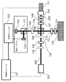
従来技術と一致する、偏光多重基準システムOCTシステムのようなOCTシステムが、図1に描かれている。スーパールミネッセントダイオード(SLD)101のような広帯域光源が、ファイバコリメータ(図示せず)を用いてある長さの光ファイバ123を通じてファイバ結合され、コリメートされた光ビーム102を放射し、コリメートされた光ビーム102は、半波長板104を通じて任意の偏光子103を透過され、偏光ビームスプリッタ105によって基準放射106及びプローブ放射112に分割される。光ファイバ123の長さは、光学放射をフィルタリングする空間フィルタとして作用し、それにより、干渉信号の質を向上させる。
An OCT system, such as a polarization multiple reference system OCT system, consistent with the prior art is depicted in FIG. A broadband light source, such as a super luminescent diode (SLD) 101, is fiber coupled through a length of
基準放射106は、減衰器107及び四分の一波長板108を透過させられ、次に、部分反射ミラー109を部分的に透過させられて、ボイスコイル又は圧電デバイスのような振動変換デバイス111(oscillating
translation device)に取り付けられた基準ミラー110に至る。部分ミラー109及び基準ミラー110の組み合わせは、参照として本明細書に援用する特許に記載されているように複数の基準信号を生成する。
The
to the
反射された基準放射は四分の一波長板108を通じて戻されると、その偏光ベクトルは、偏光ベクトルが偏光ビームスプリッタ105によって図1の破線のボックス内に描かれる検出システムに向かって再度方向付けられるように、回転させられる。
When the reflected reference radiation is returned through the
プローブ放射112は、第2の四分の一波長板113を透過させられ、基準経路内の光学素子の影響を補償する反射防止被覆ブランクを透過させられる。プローブ放射112は、標的115内の成分によって散乱させられる。プローブ放射の一部は、四分の一波長板113を通じて後方散乱させられ、四分の一波長板113の二度の通過は、その偏光ベクトルを90度だけ回転させ、それにより、この散乱させられたプローブ放射が、検出系に向かって偏光ビームスプリッタ105を透過させられるのを可能にする。
The
合成された散乱させられたプローブ放射及び反射させられた基準放射は、任意的な第2の半波長板116を透過させられて、第2の偏光ビームスプリッタ117に至り、第2の偏光ビームスプリッタは、反射させられた基準放射及び散乱させられたプローブ放射の成分の1つのセットを検出器118に反射し、反射させられた基準放射及び散乱させられたプローブ放射の成分の直交セットを検出器119に送り、それにより、バランスの取れた検出を達成する。
The combined scattered probe radiation and reflected reference radiation are transmitted through the optional second half-
幾つかの実施態様において、任意的な第2の半波長板116は存在しないが、第2の偏光ビームスプリッタ117は、光ビーム120の周りで45度回転させられるので、偏光ビームスプリッタ117は、再び、反射させられた基準放射及び散乱させられたプローブ放射の成分の1つのセットを検出器118に反射し、反射させられた基準放射及び散乱させられたプローブ放射の成分の直交セットを検出器119に送る。
In some embodiments, the optional second half-
OCTシステムの動作は、制御モジュール121によって制御される。検出される信号は、処理モジュール122によって処理されて、標的の撮像及び解析をもたらす。OCTシステムは、典型的に、基準放射及びプローブ放射を集束させる1つ又はそれよりも多くのレンズを含む。図1に描く実施態様では、単一のレンズ124が、基準放射及びプローブ放射の両方を集束させる。そのようなシステムは、典型的に、1つ又はそれよりも多くの検出器レンズも含む。
The operation of the OCT system is controlled by the
描写する実施態様において、コリメートされた光ビーム102を放射するスーパールミネッセントダイオード(SLD)及びレンズの組み合わせ101のような広帯域光源は、コリメートされたビームを光学系の残部に送出するファイバコリメータを介してSLDを結合するファイバを含む。そのようなファイバ結合システムにおいて、ファイバは、高品質のコリメートされたビームを送出する空間フィルタとして作用する。ファイバベースのOCTシステムでは、(自由空間OCTシステムと対照的に)、ビームスプリッタ機能は、典型的に、ファイバにおいても達成され、従って、広範囲のファイバベースの空間フィルタリングがある。
In the depicted embodiment, a broadband light source, such as a superluminescent diode (SLD) and
しかしながら、SLD源とコリメートされたビームとの間のファイバ結合のない自由空間ベースのOCTシステムでは、空間フィルタリングの欠如は、OCTシステムの性能を低下させる。SLDの出力をピンホールを通じて集束させることによって空間フィルタリングを達成するアプローチは、複雑さを加えることに加えて、反射させてSLDに光を戻すという望ましくない結果を有し、それは許容できない雑音に関連する問題を引き起こし得る。 However, in free space based OCT systems without fiber coupling between the SLD source and the collimated beam, the lack of spatial filtering reduces the performance of the OCT system. The approach of achieving spatial filtering by focusing the output of the SLD through a pinhole has the undesirable consequence of reflecting it back to the SLD in addition to adding complexity, which is related to unacceptable noise Can cause problems.
典型的には偏光成分を用いる、光アイソレータを、SLD源とピンホールとの間に設置して、ピンホールからSLDに反射させられて戻る望ましくない光を実質的に低減させることができる。しかしながら、このアプローチは、コスト及び複雑さに関連する追加的な光学部品(optical component)を必要とする。 An optical isolator, typically using a polarization component, can be placed between the SLD source and the pinhole to substantially reduce unwanted light reflected back from the pinhole to the SLD. However, this approach requires additional optical components related to cost and complexity.
ファイバベースのOCTシステムは、光ビームのファイバ空間フィルタリングの利点を有するが、自由空間OCTシステムは、潜在的に極めて低コストであり、それにより、有意な商業的利点をもたらすという、有意な利点を有する。従って、SLDに戻される望ましくない反射がなく、追加的な光学部品を必要としない、空間フィルタリングを有する自由空間OCTシステムの必要は、満たされていない。 While fiber-based OCT systems have the advantage of fiber spatial filtering of the light beam, free-space OCT systems have the significant advantage that they are potentially very low cost, thereby providing significant commercial advantages. Have. Thus, the need for a free space OCT system with spatial filtering that does not have undesirable reflections back into the SLD and does not require additional optical components is unmet.
本明細書に記載する発明は、光学源に戻る問題の反射が実質的にない自由空間光コヒーレンス断層映像法(OCT)システムの光ビームに対して空間フィルタリングを適用する方法及び装置を提供する。本発明は、OCTシステムの基準ビームを空間的にフィルタリングすることを提供する。空間的にフィルタリングされる基準ビームは、空間的にフィルタリングされる基準ビームに対応するプローブ放射の部分との干渉信号を形成するだけであり、それにより、完全な干渉信号を効果的に空間的にフィルタリングする。参照ビームを空間的にフィルタリングすることに起因する望ましくない反射は、望ましくない光学フィードバックからの光学源の隔離を提供するOCT設計から利益を享受し、それにより、光学源への望ましくない反射を生成せずに空間フィルタリングを達成する。 The invention described herein provides a method and apparatus for applying spatial filtering to a light beam of a free space optical coherence tomography (OCT) system that is substantially free of problematic reflections back to the optical source. The present invention provides for spatially filtering the reference beam of an OCT system. The spatially filtered reference beam only forms an interference signal with the portion of the probe radiation that corresponds to the spatially filtered reference beam, thereby effectively spatially filtering the complete interference signal. Filter. Undesirable reflections due to spatial filtering of the reference beam benefit from an OCT design that provides isolation of the optical source from unwanted optical feedback, thereby producing undesirable reflections on the optical source Achieving spatial filtering without
本発明は、改善された自由空間光学コヒーレンス断層映像法システムを提供する。放射源と、少なくとも1つのプローブビームと、1つの基準ビームとを含む、システムにおいて、本発明のシステムは、基準ビームが空間的にフィルタリングされることで、空間的にフィルタリングされる基準ビームの部分が、空間的にフィルタリングされる基準ビームの部分に対応するプローブ放射の部分を備える、少なくとも1つの干渉信号を形成し、それにより、結果として得られる干渉信号を効果的に空間的にフィルタリングする。 The present invention provides an improved free space optical coherence tomography system. In a system comprising a radiation source, at least one probe beam, and one reference beam, the system of the present invention provides a portion of the reference beam that is spatially filtered by spatially filtering the reference beam. Form at least one interference signal comprising a portion of the probe radiation corresponding to the portion of the reference beam that is spatially filtered, thereby effectively spatially filtering the resulting interference signal.
基準ビームは、基準ビームを所定の領域で反射的である表面に集束させることによって空間的にフィルタリングされ、その領域は、コリメートされるビームの直径より実質的に小さい直径を有し、典型的に、集束させられる基準ビームのウエストの寸法の1〜4倍と略等しい範囲内にある。 The reference beam is spatially filtered by focusing the reference beam on a surface that is reflective in a predetermined area, which area has a diameter substantially smaller than the diameter of the collimated beam, typically , In a range approximately equal to 1 to 4 times the waist dimension of the reference beam to be focused.
好適な実施態様において、その領域は、部分的に反射的であり、80〜95%の範囲内の反射率を備える。 In a preferred embodiment, the region is partially reflective with a reflectivity in the range of 80-95%.
代替的な実施態様において、部分的に反射的な表面は、屈折率分布型レンズの表面である。 In an alternative embodiment, the partially reflective surface is the surface of a gradient index lens.
他の実施態様において、所定の反射率の領域を有する表面は、基準ミラーの表面である。その領域は、集束させられる基準ビームのウエストの寸法の1〜4倍と略等しい範囲内の直径を有する。フーリエ領域OCT又は従来的な領域OCTのような、これらの実施形態の一部では、部分ミラーがない。 In another embodiment, the surface having the predetermined reflectivity region is the surface of the reference mirror. The region has a diameter in a range approximately equal to 1 to 4 times the waist dimension of the reference beam to be focused. In some of these embodiments, such as Fourier domain OCT or conventional domain OCT, there are no partial mirrors.
代替的な実施態様では、反射率の基準ミラー領域に加えて、80〜95%の範囲内の反射率の所定の領域も有し、集束させられる基準ビームのウエストの寸法の1〜4倍と略等しい範囲内の直径も有する、追加的な又は第2の表面が、基準ミラー表面からの反射を受けるように方向付けられる。 In an alternative embodiment, in addition to the reference mirror area of reflectivity, it also has a predetermined area of reflectivity in the range of 80-95%, and 1-4 times the waist dimension of the reference beam to be focused. An additional or second surface, also having a diameter within a substantially equal range, is oriented to receive reflection from the reference mirror surface.
1つの実施態様において、本発明は、改良された自由空間光コヒーレンス断層映像法システムを提供し、当該システムは、幾つかある必要なコンポーネントの中でも、基準放射及びプローブ放射を生成する放射源と、検出器と、基準放射のための経路であって、(80〜95パーセントの範囲内で反射する)部分ミラーを含む経路と、基準ミラーと、プローブ放射のための経路と、基準放射及びプローブ放射によって形成され且つ検出器で受信される干渉信号を捕捉し且つ処理する手段とを含み、改良点は、部分ミラーが、その反射表面に事前に選択される領域を有することで、部分ミラーの事前に選択される領域と基準ミラーとの間で反射させられる放射が選択され、実質的に全ての他の放射が基準信号から濾過されることを含む。 In one embodiment, the present invention provides an improved free space optical coherence tomography system that includes a radiation source that generates reference radiation and probe radiation, among other required components, A detector, a path for reference radiation, including a partial mirror (reflecting within a range of 80-95 percent), a reference mirror, a path for probe radiation, a reference radiation and a probe radiation Means for capturing and processing the interference signal formed by and received at the detector, the improvement being that the partial mirror has a preselected region on its reflective surface, so Radiation selected between the region selected and the reference mirror is selected, including substantially all other radiation being filtered from the reference signal.
部分ミラーの事前に選択される領域は、集束させられる基準ビームのウエストの寸法の値の1〜4倍と略等しい範囲内の直径を有する。 The preselected area of the partial mirror has a diameter in a range approximately equal to 1 to 4 times the waist dimension value of the reference beam to be focused.
代替的に、改良された自由空間光コヒーレンス断層映像法システムを提供する実施態様において、当該システムは、基準放射及びプローブ放射を生成する放射源と、検出器と、基準放射のための経路と、基準ミラーと、プローブ放射のための経路と、基準放射及びプローブ放射によって形成され且つ検出器で受信される干渉信号を捕捉し且つ処理する手段とを含む、全ての機能的なコンポーネントを含み、改良点は、基準ミラーが、その反射表面に事前に選択される領域を有することで、所定の領域から反射される放射が選択され、実質的に全ての他の放射が前記基準信号から濾過されることを含む。事前に選択される領域は、集束させられる基準ビームのウエストの寸法の値の1〜4倍と略等しい範囲内の直径を有する。 Alternatively, in an embodiment that provides an improved free space optical coherence tomography system, the system includes a radiation source that generates reference radiation and probe radiation, a detector, and a path for the reference radiation; Includes and improves all functional components including a reference mirror, a path for probe radiation, and means for capturing and processing interference signals formed by the reference radiation and probe radiation and received at the detector The point is that the reference mirror has a preselected region on its reflective surface so that radiation reflected from a given region is selected and substantially all other radiation is filtered from the reference signal. Including that. The preselected region has a diameter in a range approximately equal to 1 to 4 times the value of the waist dimension of the reference beam to be focused.
図面に示されて或いは発明の詳細な説明において議論されて、様々な他の実施態様が本発明に含められている。 Various other embodiments are included in the present invention as shown in the drawings or discussed in the detailed description of the invention.
図面は、本発明を理解する助けとして意図されている。 The drawings are intended as an aid to understanding the present invention.
本明細書に記載する発明は、光コヒーレンス断層映像法(OCT)システムのような干渉光学システムの基準ビームを空間的にフィルタリングし、それにより、関連する干渉信号の信号対雑音比を改善する方法、装置及びシステムを提供する。空間的にフィルタリングされた基準ビームは、基準ビームの空間的にフィルタリングされた部分に対応するプローブ放射の部分だけで干渉信号を形成するので、基準ビームを空間的にフィルタリングすることは、それにより、干渉信号を効果的に空間的にフィルタリングする。 The invention described herein provides a method for spatially filtering a reference beam of an interferometric optical system, such as an optical coherence tomography (OCT) system, thereby improving the signal-to-noise ratio of the associated interference signal. An apparatus and system are provided. Since the spatially filtered reference beam forms an interference signal with only the portion of the probe radiation that corresponds to the spatially filtered portion of the reference beam, spatially filtering the reference beam thereby Effectively spatially filter the interference signal.
図1は、本明細書において前に議論した。 FIG. 1 was previously discussed herein.
好適な実施態様が図2に描写されており、多くの点において(同じ番号で示されるような)図1に描写されるシステムと同じである。しかしながら、部分ミラー209、そして、任意的に、基準ミラー210(reference mirror)は、異なるものであり、図4においてより詳細に記載されている。その上、コリメートされた光ビーム202を出力する光学源201(optical source)は、自由空間構成(free space configuration)であり、図3により詳細に描写されている。
A preferred embodiment is depicted in FIG. 2 and is in many respects the same as the system depicted in FIG. 1 (as indicated by the same number). However, the
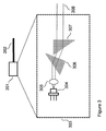
図3の破線のボックス303は、その光出力が典型的には非球面レンズ(又は代替的にレンズ系)であるレンズ305によってコリメートされる、TO缶(トランジスタアウトライン缶)(transistor outline can)(又は代替的にチップレベルデバイス(chip level device))内のSLD304を描写している。代替的な実施態様において、コリメートされたビームは、アナモルフィック対のプリズム306及び307によって丸くされて、(図2の202に対応する)コリメートされた丸いビーム308を出力する。
The dashed
シート4の図4Aには、図2の基準経路(reference path)が再び示されており、(図2の)部分ミラー209を含む光学素子が、図4B、4C及び(任意的に)4Dにより詳細に描写されている。光学素子412は、片面に部分ミラー面又はコーティング413を有する。好適な実施形態において、部分反射ミラーは、80%〜95%の範囲内の反射率を有さなければならない。他の表面414は、(実施形態に依存して)反射防止コーティングされてよく、コーティングされなくてよく、或いは特定の反射率のためにコーティングされてよい。
In FIG. 4A of sheet 4, the reference path of FIG. 2 is again shown, and the optical element including the partial mirror 209 (of FIG. 2) is shown in FIGS. 4B, 4C and (optionally) 4D. Depicted in detail. The
図4Cは、本発明の鍵となる重要な特徴を描写している。図4Cは、図4Bの部分ミラー面413の端面図を描写しており、部分ミラーが、典型的には、中央にあり、典型的には(必ずしも必要でないが)丸い、小さい領域15に閉じ込められることを示している。この所定の部分反射領域415の最適な大きさは、レンズ124によって集束させられる光ビームのビームウエスト(beam waist)に依存する。
FIG. 4C depicts an important feature of the present invention. 4C depicts an end view of the
集束ビームのウエストの直径は、コリメートされたビームの直径及び集束レンズの焦点距離に依存する。典型的な用途において、集束ビームのウエストの直径は、20〜50ミクロンである。従って、所定の反射領域415の直径は、典型的には、20〜60ミクロンである。図4Dは、図4Bと同じ光学系の図を示しており、(図4Cの領域415に類似する)所定の部分反射領域416を含まない表面の任意の傾斜したプロファイル417を示している。傾斜したプロファイルは、経路上にない放射を光学系から光学システムの反射領域415に導き、それにより、そのような放射が雑音(ノイズ)を生成するのを防止する。
The waist diameter of the focused beam depends on the diameter of the collimated beam and the focal length of the focusing lens. In typical applications, the focused beam waist diameter is 20-50 microns. Accordingly, the diameter of the predetermined
代替的な実施態様において、レンズ124は、ホログラフィックレンズ(holographic lens)である。
In an alternative embodiment,
幾つかの実施形態において、基準放射(reference radiation)及びプローブ放射(probe radiation)の両方を集束させる単一のレンズ124が、2つのレンズによって置き換えられている。図5Aは、図2の単一のレンズ124が基準経路内のレンズ524によって並びにプローブ経路内のレンズ525によって置き換えられた、図2のシステムのサブセットを描写している。幾つかの実施態様において、1つのレンズは、屈折率分布型レンズである。代替的な実施態様において、両方のレンズは、GRIN(gradient index)(屈折率分布型)レンズである。
In some embodiments, a
縮小された大きさの部分ミラーを有することの効果は、それがピンホールとして効果的に挙動し、それにより、基準ビーム(reference beam)を空間的にフィルタリングすることである。好適な実施態様において、空間的にフィルタリングされた基準放射の部分でない放射は、(本明細書中に参照として援用する)米国仮特許出願第62/096,909号に記載された技法によって伝搬して光学源に戻されることが実質的に防止される。 The effect of having a reduced size partial mirror is that it behaves effectively as a pinhole, thereby spatially filtering the reference beam. In a preferred embodiment, the radiation that is not part of the spatially filtered reference radiation is propagated by the technique described in US Provisional Patent Application No. 62 / 096,909 (incorporated herein by reference). Thus, it is substantially prevented from returning to the optical source.
図4Dは、光学素子412(optic)の角度付きバージョンを提供する代替的な実施態様を描写しており、417によって示すように、部分ミラー416は、平坦な表面であるが、光学部品のその側面の残部は傾斜させられている。角度付き光学素子は、それがノイズを発生させ得ないよう、光学系からの望ましくない放射を方向付ける。
FIG. 4D depicts an alternative embodiment that provides an angled version of optical element 412 (optic), as shown by 417,
(図2の)単一のレンズ124が基準経路レンズ524及びプローブ経路レンズ525と置換されている、シート5の図5Bに描写される幾つかの実施態様において、基準経路レンズ525及び部分ミラー525は、GRIN(勾配屈折率)レンズの面528上の縮小された部分反射要素530を備えるGRINレンズ526と置換されており、縮小された面積(area)の部分反射要素の大きさ及び位置は、所望の基準放射のみが縮小された面積の部分反射要素によって反射させられ、それにより、基準放射を空間的にフィルタリングするような、大きさ及び位置である。この実施態様の利点は、縮小された面積の部分反射要素が集束ビームのウエスト内の場所に物理的に固定され、それにより、コンポーネント(構成部品)の整列(位置合わせ)に余り敏感でないことである。
In some embodiments depicted in FIG. 5B of sheet 5 where a single lens 124 (of FIG. 2) is replaced with a
他の実施態様において、基準ミラー210を備える光学素子は、縮小された面積の反射領域(region)を含み、幾つかの実施態様において、基準ミラー光学素子の残部も、図4Dに描写されるのと同様に傾斜させられる。幾つかの実施態様において、基準ミラー210に対するこの変更は、部分ミラー209,413と類似の変形の代替である。更なる実施態様において、部分ミラー及び基準ミラーの両方は、予め選択された反射率の領域を有し、部分ミラーの場合、反射率は80〜95%であり、基準ミラーの場合、反射率は約100%である。典型的には、縮小された面積の反射要素(部分ミラー又は完全ミラーのいずれか)は円形であるが、幾つかの実施態様では、楕円のような他の形状が好ましい。
In other embodiments, the optical element comprising the
好適な実施態様を多重基準OCTシステムの偏光バージョンに関して記載したが、本発明を任意の(偏光又は非偏光)自由空間OCTシステムに適用することができ、或いは正に如何なる自由空間干渉計システムにも適用することができる。フーリエ領域(Fourier domain)OCT、従来的な時間領域(time domain)OCT又は全域(full field)OCTの場合には、いずれも部分ミラーを必要とせず、基準ミラーは縮小された面積の領域反射要素を含む。 Although the preferred embodiment has been described with reference to a polarized version of a multi-reference OCT system, the present invention can be applied to any (polarized or unpolarized) free space OCT system, or just to any free space interferometer system. Can be applied. In the case of Fourier domain OCT, conventional time domain OCT or full field OCT, none of the partial mirrors are required, and the reference mirror is a reduced area reflective element. including.
本発明は、一般的に、自由空間OCTシステムに適用可能であり、空間的にフィルタリングされた基準ビームを提供し、空間的にフィルタリングされた基準ビームの部分は、空間的にフィルタリングされた基準ビームの部分に対応するプローブ放射の部分のみを備える少なくとも1つの干渉信号を形成し、それにより、その結果得られる干渉信号を効果的に空間的にフィルタリングする。 The present invention is generally applicable to free space OCT systems and provides a spatially filtered reference beam, where a portion of the spatially filtered reference beam is a spatially filtered reference beam. Forming at least one interference signal comprising only a portion of the probe radiation corresponding to that portion, thereby effectively spatially filtering the resulting interference signal.
好適な実施態様において、縮小された面積の反射領域は、有効な(又は反射的な)ピンホールとして作用する。他の実施態様では、基準ビームを空間的にフィルタリングするために、1つ又はそれよりも多くの実際のピンホールが使用される。そのようなピンホールは、20〜60ミクロンの直径を有する。幾つかの実施態様において、基準ビームは、集束された基準ビームのウエストの小さい丸い部分のみを透過するピンホール内に集束され、それにより、基準ビームを空間的にフィルタリングする。 In a preferred embodiment, the reduced area reflective region acts as an effective (or reflective) pinhole. In other embodiments, one or more actual pinholes are used to spatially filter the reference beam. Such pinholes have a diameter of 20-60 microns. In some embodiments, the reference beam is focused into a pinhole that transmits only a small round portion of the focused reference beam's waist, thereby spatially filtering the reference beam.
基準ビームのみを空間的にフィルタリングすることは、その内容を本明細書中に参照として援用する、「A polarized OCT system with improved SNR」という名称の米国仮特許出願第62/096,909号に記載されている望ましくない雑音生成光学フィードバックから光学源を隔離する技法の利用を可能にする。幾つかの実施態様において、基準ビームは、集束ビームのウエストに関連する小さな領域でのみ反射する反射面に基準ビームを集束させることによって空間的にフィルタリングされる。 Spatial filtering of only the reference beam is described in US Provisional Patent Application No. 62 / 096,909 entitled “A polarized OCT system with improved SNR”, the contents of which are incorporated herein by reference. It enables the use of techniques to isolate the optical source from unwanted unwanted noise generating optical feedback. In some embodiments, the reference beam is spatially filtered by focusing the reference beam on a reflective surface that reflects only in a small area associated with the waist of the focused beam.
所定の反射領域を有し、反射領域の大きさが集束ビームのウエストに関連する、実施態様において、415は、典型的には80〜95%の反射率を有する、部分反射面である。幾つかの実施態様において、部分反射面415は、GRINレンズの表面413である。代替的に、所定の反射領域を有する表面が、基準ミラー面210である。
In an embodiment having a predetermined reflective area, where the size of the reflective area is related to the waist of the focused beam, 415 is a partially reflective surface, typically having a reflectivity of 80-95%. In some embodiments, the partially
当業者は、本発明の精神及び範囲内で、多くの変更および変形を行い得る。従って、請求項の範囲内で、本発明は、本明細書に具体的に記載される方法と別の方法で実施されてよいことが理解されるべきである。 Those skilled in the art may make many modifications and variations within the spirit and scope of the present invention. Therefore, it is to be understood that, within the scope of the claims, the present invention may be practiced otherwise than as specifically described herein.
Claims (10)
自由空間光コヒーレンス断層映像法システムであって、
前記放射源は、少なくとも1つのプローブビームと、1つの基準ビームとを生成し、当該自由空間光コヒーレンス断層映像法システムの前記基準ビームは、空間的にフィルタリングされ、該空間的にフィルタリングされる基準ビームの部分が、前記空間的にフィルタリングされる基準ビームの前記部分に対応する前記プローブ放射の部分を備える、少なくとも1つの干渉信号を形成し、それにより、該結果として得られる干渉信号を効果的に空間的にフィルタリングする、
自由空間光コヒーレンス断層映像法システム。 Including radiation sources,
A free-space optical coherence tomography system,
The radiation source generates at least one probe beam and one reference beam, the reference beam of the free space optical coherence tomography system being spatially filtered and the spatially filtered reference A portion of the beam forms at least one interference signal comprising a portion of the probe radiation corresponding to the portion of the spatially filtered reference beam, thereby effectively reducing the resulting interference signal To spatially filter,
Free-space optical coherence tomography system.
前記部分ミラーは、その反射表面に事前に選択される領域を有することで、前記部分ミラーの前記事前に選択される領域と前記基準ミラーとの間で反射させられる放射が選択され、実質的に全ての他の放射が前記基準信号から濾過される、
改良された自由空間光コヒーレンス断層映像法システム。 A radiation source for generating reference radiation and probe radiation; a detector; a path for reference radiation comprising a partial mirror reflecting within a range of 80-95 percent; a reference mirror; And a means for capturing and processing an interference signal formed by the reference radiation and the probe radiation and received at the detector;
The partial mirror has a preselected region on its reflective surface so that radiation reflected between the preselected region of the partial mirror and the reference mirror is selected and substantially All other radiation is filtered from the reference signal,
Improved free-space optical coherence tomography system.
前記基準ミラーは、その反射表面に事前に選択される領域を有することで、前記所定の領域から反射される放射が選択され、実質的に全ての他の放射が前記基準信号から濾過される、
改良された自由空間光コヒーレンス断層映像法システム。 A radiation source for generating reference radiation and probe radiation, a detector, a path for reference radiation, a reference mirror, a path for probe radiation, and formed by the reference radiation and the probe radiation and the detector Means for capturing and processing interfering signals received at
The reference mirror has a preselected area on its reflective surface so that radiation reflected from the predetermined area is selected and substantially all other radiation is filtered from the reference signal;
Improved free-space optical coherence tomography system.
Applications Claiming Priority (3)
| Application Number | Priority Date | Filing Date | Title |
|---|---|---|---|
| US201562099521P | 2015-01-04 | 2015-01-04 | |
| US62/099,521 | 2015-01-04 | ||
| PCT/US2016/012002 WO2016109844A1 (en) | 2015-01-04 | 2016-01-01 | Reference signal filter for interferometric system |
Publications (2)
| Publication Number | Publication Date |
|---|---|
| JP2018500575A true JP2018500575A (en) | 2018-01-11 |
| JP2018500575A5 JP2018500575A5 (en) | 2019-02-07 |
Family
ID=56285095
Family Applications (1)
| Application Number | Title | Priority Date | Filing Date |
|---|---|---|---|
| JP2017535658A Pending JP2018500575A (en) | 2015-01-04 | 2016-01-01 | Reference signal filter for interference systems |
Country Status (4)
| Country | Link |
|---|---|
| US (2) | US10018461B2 (en) |
| EP (1) | EP3240990A4 (en) |
| JP (1) | JP2018500575A (en) |
| WO (1) | WO2016109844A1 (en) |
Cited By (1)
| Publication number | Priority date | Publication date | Assignee | Title |
|---|---|---|---|---|
| KR20230099700A (en) * | 2021-12-27 | 2023-07-04 | 재단법인 구미전자정보기술원 | Apparatus for obtaining suface shape information using a single light source |
Families Citing this family (5)
| Publication number | Priority date | Publication date | Assignee | Title |
|---|---|---|---|---|
| US9892334B2 (en) | 2015-11-01 | 2018-02-13 | Joshua Noel Hogan | Optical coherence tomography array based subdermal imaging device |
| CN109313119B (en) * | 2016-06-20 | 2021-11-02 | 普莱尔股份公司 | Device and method for detecting and/or characterizing fluid-borne particles |
| JP6245590B1 (en) * | 2016-06-20 | 2017-12-13 | 公立大学法人大阪市立大学 | Skin diagnostic device, skin condition output method, program, and recording medium |
| WO2018129435A1 (en) * | 2017-01-09 | 2018-07-12 | Mks Technology, Inc. | Method of measuring raman scattering and related spectrometers and laser sources |
| US10314491B2 (en) * | 2017-02-11 | 2019-06-11 | The General Hospital Corporation | Optics for apodizing an optical imaging probe beam |
Citations (6)
| Publication number | Priority date | Publication date | Assignee | Title |
|---|---|---|---|---|
| JPH08297009A (en) * | 1995-04-07 | 1996-11-12 | Discovision Assoc | Interferometer having micro-mirror |
| US20060089548A1 (en) * | 2004-10-23 | 2006-04-27 | Hogan Josh N | Correlation of concurrent non-invasively acquired signals |
| JP2007524075A (en) * | 2003-06-19 | 2007-08-23 | マサチユセツツ・インスチチユート・オブ・テクノロジイ | Phase measuring system and method |
| US20080317201A1 (en) * | 2007-06-22 | 2008-12-25 | Hogan Josh N | Orthogonal reference analysis system with enhanced SNR |
| US20120307035A1 (en) * | 2011-01-25 | 2012-12-06 | Zahid Yaqoob | Single-shot full-field reflection phase microscopy |
| US20140160482A1 (en) * | 2012-12-07 | 2014-06-12 | The General Hospital Corporation | Optical system for endoscopic internally-referenced interferometric imaging, and method for employing the same |
Family Cites Families (7)
| Publication number | Priority date | Publication date | Assignee | Title |
|---|---|---|---|---|
| US4789219A (en) * | 1986-03-06 | 1988-12-06 | The United States Of America As Represented By The United States Department Of Energy | Gradient index retroreflector |
| US6725073B1 (en) | 1999-08-17 | 2004-04-20 | Board Of Regents, The University Of Texas System | Methods for noninvasive analyte sensing |
| US7751862B2 (en) | 2004-08-19 | 2010-07-06 | Fp Technology | Frequency resolved imaging system |
| US7526329B2 (en) | 2004-08-19 | 2009-04-28 | Hogan Josh N | Multiple reference non-invasive analysis system |
| GB0907277D0 (en) * | 2009-04-29 | 2009-06-10 | Univ Kent Kanterbury | Method for depth resolved wavefront sensing, depth resolved wavefront sensors and method and apparatus for optical imaging |
| US8767217B2 (en) * | 2011-07-29 | 2014-07-01 | Tornado Spectral Systems, Inc. | Time domain-frequency domain optical coherence tomography apparatus and methods for use |
| US9574868B2 (en) * | 2012-03-21 | 2017-02-21 | Ramot At Tel-Aviv University Ltd. | Portable interferometric device |
-
2016
- 2016-01-01 WO PCT/US2016/012002 patent/WO2016109844A1/en active Application Filing
- 2016-01-01 JP JP2017535658A patent/JP2018500575A/en active Pending
- 2016-01-01 US US15/539,945 patent/US10018461B2/en not_active Expired - Fee Related
- 2016-01-01 EP EP16732899.6A patent/EP3240990A4/en not_active Withdrawn
-
2018
- 2018-06-06 US US16/001,787 patent/US20180328712A1/en not_active Abandoned
Patent Citations (6)
| Publication number | Priority date | Publication date | Assignee | Title |
|---|---|---|---|---|
| JPH08297009A (en) * | 1995-04-07 | 1996-11-12 | Discovision Assoc | Interferometer having micro-mirror |
| JP2007524075A (en) * | 2003-06-19 | 2007-08-23 | マサチユセツツ・インスチチユート・オブ・テクノロジイ | Phase measuring system and method |
| US20060089548A1 (en) * | 2004-10-23 | 2006-04-27 | Hogan Josh N | Correlation of concurrent non-invasively acquired signals |
| US20080317201A1 (en) * | 2007-06-22 | 2008-12-25 | Hogan Josh N | Orthogonal reference analysis system with enhanced SNR |
| US20120307035A1 (en) * | 2011-01-25 | 2012-12-06 | Zahid Yaqoob | Single-shot full-field reflection phase microscopy |
| US20140160482A1 (en) * | 2012-12-07 | 2014-06-12 | The General Hospital Corporation | Optical system for endoscopic internally-referenced interferometric imaging, and method for employing the same |
Cited By (2)
| Publication number | Priority date | Publication date | Assignee | Title |
|---|---|---|---|---|
| KR20230099700A (en) * | 2021-12-27 | 2023-07-04 | 재단법인 구미전자정보기술원 | Apparatus for obtaining suface shape information using a single light source |
| KR102650211B1 (en) | 2021-12-27 | 2024-03-21 | 재단법인 구미전자정보기술원 | Apparatus for obtaining suface shape information using a single light source |
Also Published As
| Publication number | Publication date |
|---|---|
| US20170370699A1 (en) | 2017-12-28 |
| WO2016109844A1 (en) | 2016-07-07 |
| US10018461B2 (en) | 2018-07-10 |
| US20180328712A1 (en) | 2018-11-15 |
| EP3240990A4 (en) | 2018-07-04 |
| EP3240990A1 (en) | 2017-11-08 |
Similar Documents
| Publication | Publication Date | Title |
|---|---|---|
| US10018461B2 (en) | Reference signal filter for interferometric system | |
| US11473896B2 (en) | Coherence range imaging using common path interference | |
| JP6196206B2 (en) | Multichannel optical coherence tomography | |
| Ju et al. | Advanced multi-contrast Jones matrix optical coherence tomography for Doppler and polarization sensitive imaging | |
| US20120200859A1 (en) | Frequency-domain oct | |
| JP5591235B2 (en) | Extended range imaging | |
| US20080002211A1 (en) | System, arrangement and process for providing speckle reductions using a wave front modulation for optical coherence tomography | |
| US9492077B2 (en) | Optimized device for swept source optical coherence domain reflectometry and tomography | |
| US7884946B2 (en) | Apparatus for measurement of the axial length of an eye | |
| US8979266B2 (en) | Devices and methods for polarization-sensitive optical coherence tomography and adaptive optics | |
| JP2008519264A (en) | System and method for performing Jones matrix based analysis to measure unpolarized polarization parameters using polarization sensitive optical coherence tomography | |
| Beer et al. | Conical scan pattern for enhanced visualization of the human cornea using polarization-sensitive OCT | |
| US9841268B2 (en) | Imaging apparatus | |
| US9161687B2 (en) | Device for interferometrically measuring the eye length and the anterior eye segment | |
| US11154192B2 (en) | Method and arrangement for high-resolution topography of the cornea of an eye | |
| US10641601B2 (en) | Dual beam optical coherence tomography with simultaneous orthogonal scanning | |
| US20160183801A1 (en) | Polarized OCT with Improved SNR | |
| JP2016035402A (en) | Optical coherence tomography correction method and device therefor | |
| JP2003000541A (en) | Schematic eye for optometric apparatus | |
| JP2016083245A (en) | Optical tomography apparatus | |
| WO2019194283A1 (en) | Ophthalmic device and concave reflecting member | |
| CN113164037A (en) | Optical coherence tomography receiver | |
| CN111163681A (en) | Optical aberration of phase-sensitive optical coherence tomography measurement front section | |
| WO2018140703A1 (en) | Common-path phase-sensitive optical coherence tomography | |
| US9918631B2 (en) | Adaptive optical apparatus and ophthalmic apparatus |
Legal Events
| Date | Code | Title | Description |
|---|---|---|---|
| A521 | Request for written amendment filed |
Free format text: JAPANESE INTERMEDIATE CODE: A523 Effective date: 20181219 |
|
| A621 | Written request for application examination |
Free format text: JAPANESE INTERMEDIATE CODE: A621 Effective date: 20181219 |
|
| A977 | Report on retrieval |
Free format text: JAPANESE INTERMEDIATE CODE: A971007 Effective date: 20191023 |
|
| A131 | Notification of reasons for refusal |
Free format text: JAPANESE INTERMEDIATE CODE: A131 Effective date: 20191126 |
|
| A521 | Request for written amendment filed |
Free format text: JAPANESE INTERMEDIATE CODE: A523 Effective date: 20200225 |
|
| A02 | Decision of refusal |
Free format text: JAPANESE INTERMEDIATE CODE: A02 Effective date: 20200602 |