JP2018500491A - Turbine blade with axial tip cooling circuit - Google Patents
Turbine blade with axial tip cooling circuit Download PDFInfo
- Publication number
- JP2018500491A JP2018500491A JP2017525580A JP2017525580A JP2018500491A JP 2018500491 A JP2018500491 A JP 2018500491A JP 2017525580 A JP2017525580 A JP 2017525580A JP 2017525580 A JP2017525580 A JP 2017525580A JP 2018500491 A JP2018500491 A JP 2018500491A
- Authority
- JP
- Japan
- Prior art keywords
- cooling circuit
- leading edge
- tip
- cooling
- wall
- Prior art date
- Legal status (The legal status is an assumption and is not a legal conclusion. Google has not performed a legal analysis and makes no representation as to the accuracy of the status listed.)
- Granted
Links
Images


Classifications
-
- F—MECHANICAL ENGINEERING; LIGHTING; HEATING; WEAPONS; BLASTING
- F01—MACHINES OR ENGINES IN GENERAL; ENGINE PLANTS IN GENERAL; STEAM ENGINES
- F01D—NON-POSITIVE DISPLACEMENT MACHINES OR ENGINES, e.g. STEAM TURBINES
- F01D5/00—Blades; Blade-carrying members; Heating, heat-insulating, cooling or antivibration means on the blades or the members
- F01D5/12—Blades
- F01D5/14—Form or construction
- F01D5/18—Hollow blades, i.e. blades with cooling or heating channels or cavities; Heating, heat-insulating or cooling means on blades
- F01D5/187—Convection cooling
-
- F—MECHANICAL ENGINEERING; LIGHTING; HEATING; WEAPONS; BLASTING
- F01—MACHINES OR ENGINES IN GENERAL; ENGINE PLANTS IN GENERAL; STEAM ENGINES
- F01D—NON-POSITIVE DISPLACEMENT MACHINES OR ENGINES, e.g. STEAM TURBINES
- F01D5/00—Blades; Blade-carrying members; Heating, heat-insulating, cooling or antivibration means on the blades or the members
- F01D5/12—Blades
- F01D5/14—Form or construction
- F01D5/20—Specially-shaped blade tips to seal space between tips and stator
-
- F—MECHANICAL ENGINEERING; LIGHTING; HEATING; WEAPONS; BLASTING
- F05—INDEXING SCHEMES RELATING TO ENGINES OR PUMPS IN VARIOUS SUBCLASSES OF CLASSES F01-F04
- F05D—INDEXING SCHEME FOR ASPECTS RELATING TO NON-POSITIVE-DISPLACEMENT MACHINES OR ENGINES, GAS-TURBINES OR JET-PROPULSION PLANTS
- F05D2220/00—Application
- F05D2220/30—Application in turbines
- F05D2220/32—Application in turbines in gas turbines
-
- F—MECHANICAL ENGINEERING; LIGHTING; HEATING; WEAPONS; BLASTING
- F05—INDEXING SCHEMES RELATING TO ENGINES OR PUMPS IN VARIOUS SUBCLASSES OF CLASSES F01-F04
- F05D—INDEXING SCHEME FOR ASPECTS RELATING TO NON-POSITIVE-DISPLACEMENT MACHINES OR ENGINES, GAS-TURBINES OR JET-PROPULSION PLANTS
- F05D2240/00—Components
- F05D2240/20—Rotors
- F05D2240/30—Characteristics of rotor blades, i.e. of any element transforming dynamic fluid energy to or from rotational energy and being attached to a rotor
- F05D2240/303—Characteristics of rotor blades, i.e. of any element transforming dynamic fluid energy to or from rotational energy and being attached to a rotor related to the leading edge of a rotor blade
-
- F—MECHANICAL ENGINEERING; LIGHTING; HEATING; WEAPONS; BLASTING
- F05—INDEXING SCHEMES RELATING TO ENGINES OR PUMPS IN VARIOUS SUBCLASSES OF CLASSES F01-F04
- F05D—INDEXING SCHEME FOR ASPECTS RELATING TO NON-POSITIVE-DISPLACEMENT MACHINES OR ENGINES, GAS-TURBINES OR JET-PROPULSION PLANTS
- F05D2240/00—Components
- F05D2240/20—Rotors
- F05D2240/30—Characteristics of rotor blades, i.e. of any element transforming dynamic fluid energy to or from rotational energy and being attached to a rotor
- F05D2240/304—Characteristics of rotor blades, i.e. of any element transforming dynamic fluid energy to or from rotational energy and being attached to a rotor related to the trailing edge of a rotor blade
-
- F—MECHANICAL ENGINEERING; LIGHTING; HEATING; WEAPONS; BLASTING
- F05—INDEXING SCHEMES RELATING TO ENGINES OR PUMPS IN VARIOUS SUBCLASSES OF CLASSES F01-F04
- F05D—INDEXING SCHEME FOR ASPECTS RELATING TO NON-POSITIVE-DISPLACEMENT MACHINES OR ENGINES, GAS-TURBINES OR JET-PROPULSION PLANTS
- F05D2240/00—Components
- F05D2240/20—Rotors
- F05D2240/30—Characteristics of rotor blades, i.e. of any element transforming dynamic fluid energy to or from rotational energy and being attached to a rotor
- F05D2240/307—Characteristics of rotor blades, i.e. of any element transforming dynamic fluid energy to or from rotational energy and being attached to a rotor related to the tip of a rotor blade
-
- F—MECHANICAL ENGINEERING; LIGHTING; HEATING; WEAPONS; BLASTING
- F05—INDEXING SCHEMES RELATING TO ENGINES OR PUMPS IN VARIOUS SUBCLASSES OF CLASSES F01-F04
- F05D—INDEXING SCHEME FOR ASPECTS RELATING TO NON-POSITIVE-DISPLACEMENT MACHINES OR ENGINES, GAS-TURBINES OR JET-PROPULSION PLANTS
- F05D2250/00—Geometry
- F05D2250/10—Two-dimensional
- F05D2250/18—Two-dimensional patterned
- F05D2250/185—Two-dimensional patterned serpentine-like
-
- F—MECHANICAL ENGINEERING; LIGHTING; HEATING; WEAPONS; BLASTING
- F05—INDEXING SCHEMES RELATING TO ENGINES OR PUMPS IN VARIOUS SUBCLASSES OF CLASSES F01-F04
- F05D—INDEXING SCHEME FOR ASPECTS RELATING TO NON-POSITIVE-DISPLACEMENT MACHINES OR ENGINES, GAS-TURBINES OR JET-PROPULSION PLANTS
- F05D2260/00—Function
- F05D2260/20—Heat transfer, e.g. cooling
- F05D2260/201—Heat transfer, e.g. cooling by impingement of a fluid
-
- F—MECHANICAL ENGINEERING; LIGHTING; HEATING; WEAPONS; BLASTING
- F05—INDEXING SCHEMES RELATING TO ENGINES OR PUMPS IN VARIOUS SUBCLASSES OF CLASSES F01-F04
- F05D—INDEXING SCHEME FOR ASPECTS RELATING TO NON-POSITIVE-DISPLACEMENT MACHINES OR ENGINES, GAS-TURBINES OR JET-PROPULSION PLANTS
- F05D2260/00—Function
- F05D2260/20—Heat transfer, e.g. cooling
- F05D2260/202—Heat transfer, e.g. cooling by film cooling
Abstract
本開示は、前縁冷却回路(30)と、後縁冷却回路(34)と、第1の通路(32a)及び中間通路(32b)及び最終通路(32c)を含む中間区分冷却回路(32)と、軸方向先端冷却回路(56)と、を有するタービンブレード(12)を提供する。前縁冷却回路(32)、中間区分冷却回路(32)、後縁冷却回路(34)はそれぞれ、冷却空気供給部から冷却空気流(CF)を受け取る。前縁冷却回路(30)と中間区分冷却回路(32)はそれぞれ半径方向外側端部でさらに、少なくとも1つの出口(62,64)を有しており、出口は軸方向先端冷却回路(56)に流体連通しており、これにより、前縁冷却回路(30)から出る実質的に全ての前縁冷却空気流(LEF)と、中間区分冷却回路(32)から出る実質的に全ての中間区分冷却空気流(MSF)とが、軸方向先端冷却回路(56)へと方向付けられる。The present disclosure includes an intermediate section cooling circuit (32) including a leading edge cooling circuit (30), a trailing edge cooling circuit (34), a first passage (32a), an intermediate passage (32b), and a final passage (32c). And a turbine blade (12) having an axial tip cooling circuit (56). The leading edge cooling circuit (32), the middle section cooling circuit (32), and the trailing edge cooling circuit (34) each receive a cooling air flow (CF) from a cooling air supply. The leading edge cooling circuit (30) and the intermediate section cooling circuit (32) each further have at least one outlet (62, 64) at the radially outer end, the outlet being an axial tip cooling circuit (56). To substantially all the leading edge cooling air flow (LEF) leaving the leading edge cooling circuit (30) and substantially all the middle section leaving the middle section cooling circuit (32). A cooling air flow (MSF) is directed to the axial tip cooling circuit (56).
Description
本発明は、一般にガスタービンブレードに関し、より詳細にはタービンブレードのブレード先端区分の冷却に関する。 The present invention relates generally to gas turbine blades, and more particularly to cooling the blade tip section of turbine blades.
ガスタービンエンジンのようなターボ機械では、圧縮機セクションから排出される圧縮空気が燃料と混合され、燃焼セクションで燃焼されて、高温燃焼ガスが発生する。燃焼ガスは、タービンセクション内の高温ガス路を通って方向付けられ、そこで、ガスは、通常、一列の固定ベーンと、それに続く一列の回転タービンブレードとを含む一連のタービン段を通って移動する。タービンブレードは、高温燃焼ガスからエネルギを抽出し、タービンロータを回転させて、圧縮機に動力を供給しかつ出力を提供する。 In a turbomachine, such as a gas turbine engine, compressed air exhausted from the compressor section is mixed with fuel and burned in the combustion section to generate hot combustion gases. Combustion gas is directed through a hot gas path in the turbine section where the gas typically travels through a series of turbine stages including a row of fixed vanes followed by a row of rotating turbine blades. . The turbine blades extract energy from the hot combustion gases and rotate the turbine rotor to power the compressor and provide power.
1つの形式のタービンブレードは、燃焼ガスのための半径方向内側の流路を画定するブレードプラットフォームにおける根元部から、半径方向外側のキャップ又はブレード先端区分まで延在する翼を有しており、この翼は、翼の前縁から後縁まで軸方向に延在する対向する正圧面と負圧面とを有している。タービンブレードは、高温燃焼ガスに直接さらされるので、通常、タービンブレードには内部冷却回路が設けられており、この内部冷却回路は、圧縮機抽気のようなクーラントを、ブレードの翼、翼の表面のまわりに設けられた様々なフィルム冷却孔を通して流通させる。特に、タービンブレードの前縁及び先端の冷却は、フィルム冷却により広く達成されている。しかしながら、原油やその他の重油を燃焼させるエンジンのような用途では、これらのフィルム冷却孔が詰まって、過熱してタービンブレードに損傷を与える可能性がある。 One type of turbine blade has wings extending from a root in a blade platform that defines a radially inner flow path for combustion gases to a radially outer cap or blade tip section. The wing has opposing pressure and suction surfaces extending axially from the leading edge to the trailing edge of the wing. Since turbine blades are directly exposed to high-temperature combustion gases, turbine blades are usually provided with an internal cooling circuit that provides coolant, such as compressor bleed, blade blades, blade surfaces. It is made to distribute through various film cooling holes provided around. In particular, the cooling of the leading edge and tip of the turbine blade is widely achieved by film cooling. However, in applications such as engines that burn crude oil and other heavy oils, these film cooling holes can become clogged and overheat and damage turbine blades.
本発明の1つの態様によれば、本開示は、前縁と、後縁と、正圧面壁と、負圧面壁とを画定する外壁と、先端を有する半径方向外側端部と、根元部に連結された半径方向内側端部とを有しており、前縁は、前縁を貫通して延在するフィルム冷却孔を有していない、タービンブレードを提供する。タービンブレードはさらに、外壁と共に、前縁冷却回路を画定する構造体を有しており、前縁冷却回路は、前縁に隣接しており、根元部から先端に向かって半径方向で延在している。前縁冷却回路は、少なくとも1つの前縁冷却通路を有している。このタービンブレードはさらに、外壁と共に、後縁冷却回路を画定する構造体を有しており、後縁冷却回路は、後縁に隣接し、根元部から先端に向かって半径方向で延在しており、かつ、このタービンブレードは、外壁と共に中間区分冷却回路を画定する構造体を有しており、中間区分冷却回路は、前縁冷却回路と後縁冷却回路との間に位置し、前進流蛇行状冷却回路を画定している。前進流蛇行状冷却回路は、第1の通路と、中間通路と、最終通路とを含んでいて、かつ中間区分冷却回路は、半径方向で根元部から先端に向かって延在している。タービンブレードの外壁はさらに、軸方向先端冷却回路を画定しており、軸方向先端冷却回路は、先端に隣接し、翼弦方向でほぼ連続的に延在しており、翼弦方向は、前縁から後縁へと延在している。前縁冷却回路、中間区分冷却回路、後縁冷却回路はそれぞれ、根元部における冷却空気供給部から冷却空気流を受け取る。前縁冷却回路と中間区分冷却回路はそれぞれ半径方向外側部分でさらに、少なくとも1つの出口を有しており、出口は軸方向先端冷却回路に流体連通しており、これにより、前縁冷却回路から出る実質的に全ての前縁冷却空気流と、中間区分冷却回路から出る実質的に全ての中間区分冷却空気流とが、軸方向先端冷却回路へと方向付けられる。 In accordance with one aspect of the present invention, the present disclosure provides an outer wall defining a leading edge, a trailing edge, a pressure surface wall, a suction surface wall, a radially outer end having a tip, and a root portion. The turbine blade has a connected radially inner end, and the leading edge has no film cooling holes extending through the leading edge. The turbine blade further has a structure defining, with an outer wall, a leading edge cooling circuit, the leading edge cooling circuit being adjacent to the leading edge and extending radially from the root to the tip. ing. The leading edge cooling circuit has at least one leading edge cooling passage. The turbine blade further has a structure defining, with an outer wall, a trailing edge cooling circuit, the trailing edge cooling circuit being adjacent to the trailing edge and extending radially from the root toward the tip. And the turbine blade has a structure defining an intermediate section cooling circuit with an outer wall, the intermediate section cooling circuit being located between the leading edge cooling circuit and the trailing edge cooling circuit, A serpentine cooling circuit is defined. The forward flow serpentine cooling circuit includes a first passage, an intermediate passage, and a final passage, and the intermediate section cooling circuit extends radially from the root toward the tip. The outer wall of the turbine blade further defines an axial tip cooling circuit, the axial tip cooling circuit being adjacent to the tip and extending substantially continuously in the chord direction, the chord direction being the front It extends from the edge to the trailing edge. The leading edge cooling circuit, the middle section cooling circuit, and the trailing edge cooling circuit each receive a cooling air flow from a cooling air supply at the root. The leading edge cooling circuit and the intermediate section cooling circuit each further have at least one outlet at the radially outer portion, the outlet being in fluid communication with the axial tip cooling circuit, thereby allowing the leading edge cooling circuit to Substantially all leading edge cooling airflow exiting and substantially all intermediate section cooling airflow exiting the intermediate section cooling circuit are directed to the axial tip cooling circuit.
いくつかの態様によれば、前縁冷却回路と中間区分冷却回路とは、軸方向先端冷却回路の前方端に連通しており、これにより、前縁冷却回路から出る前縁冷却空気流と、中間区分冷却回路から出る中間区分冷却空気流とは、軸方向先端冷却回路内において軸方向先端冷却回路の翼弦長さの少なくとも一部にわたって軸方向で実質的に平行である。別の態様によれば、前進流蛇行状冷却回路の中間通路及び最終通路のうちの少なくとも1つは、軸方向先端冷却回路に流体連通している。本発明の別の態様によれば、前縁冷却回路を画定する構造体は第1の壁と第2の壁とを含み、第1の壁と第2の壁とは外壁と共に、主前縁冷却通路とインピンジメント通路とを画定しており、第2の壁は、半径方向で互いに間を空けて位置する複数のインピンジメント冷却孔を有しており、これにより、前縁冷却通路とインピンジメント通路とが流体連通される。本発明の別の態様によれば、先端は複数の先端冷却孔を有しており、外壁はさらに、先端から半径方向外側に向かって延在するスクィーラ先端レールを有しており、スクィーラ先端レールは複数のスクィーラ先端孔を画定している。 According to some aspects, the leading edge cooling circuit and the middle section cooling circuit are in communication with the forward end of the axial tip cooling circuit, thereby leading to the leading edge cooling air flow exiting the leading edge cooling circuit; The middle section cooling air stream exiting the middle section cooling circuit is substantially parallel in the axial direction over at least a portion of the chord length of the axial tip cooling circuit within the axial tip cooling circuit. According to another aspect, at least one of the intermediate and final passages of the forward meandering cooling circuit is in fluid communication with the axial tip cooling circuit. In accordance with another aspect of the present invention, the structure defining the leading edge cooling circuit includes a first wall and a second wall, the first wall and the second wall together with the outer wall being the main leading edge. A cooling passage and an impingement passage, the second wall having a plurality of impingement cooling holes positioned radially apart from each other, thereby providing a leading edge cooling passage and an impingement passage. The fluid passage is in fluid communication. According to another aspect of the present invention, the tip has a plurality of tip cooling holes, the outer wall further has a squealer tip rail extending radially outward from the tip, and the squealer tip rail. Defines a plurality of squealer tip holes.
本発明の別の態様によれば、本開示は、前縁と、後縁と、正圧面壁と、負圧面壁とを画定する外壁と、先端を有する半径方向外側端部と、根元部に連結された半径方向内側端部とを有しており、前縁は、前縁を貫通して延在するフィルム冷却孔を有していない、タービンブレードを提供する。タービンブレードの外壁は、軸方向先端冷却回路を画定しており、軸方向先端冷却回路は、先端に隣接し、翼弦方向で連続的に延在しており、翼弦方向は、前縁から後縁へと延在している。タービンブレードはさらに、外壁と共に、前縁冷却空気流を供給するための前縁冷却回路を画定する構造体を有しており、前縁冷却回路は、前縁に隣接し、根元部から先端に向かって半径方向で延在している。前縁冷却回路はさらに第1の出口を有しており、出口は軸方向先端冷却回路に流体連通しており、これにより、前縁冷却回路から出る実質的に全ての前縁冷却空気流は、軸方向先端冷却回路へと方向付けられる。このタービンブレードはさらに、外壁と共に、後縁冷却回路を画定する構造体を有しており、後縁冷却回路は、後縁に隣接し、根元部から先端に向かって半径方向で延在している。タービンブレードはさらに、外壁と共に、中間区分冷却空気流を供給するための中間区分冷却回路を画定する構造体を有しており、中間区分冷却回路は、前縁冷却回路と後縁冷却回路との間に位置している。中間区分冷却回路は第2の出口を有しており、出口は軸方向先端冷却回路に流体連通しており、これにより、中間区分冷却回路から出る実質的に全ての中間区分冷却空気流が、軸方向先端冷却回路へと方向付けられる。このタービンはさらに、中間区分冷却回路と前縁冷却回路とにほぼ隣接する隔壁を有している。隔壁は、翼弦方向で延在し、隔壁下方面が、中間区分冷却回路から出る中間区分冷却空気流に対して実質的に横方向であるように配置されている。 According to another aspect of the invention, the present disclosure provides an outer wall defining a leading edge, a trailing edge, a pressure surface wall, a suction surface wall, a radially outer end having a tip, and a root portion. The turbine blade has a connected radially inner end, and the leading edge has no film cooling holes extending through the leading edge. The outer wall of the turbine blade defines an axial tip cooling circuit that is adjacent to the tip and extends continuously in the chord direction, the chord direction extending from the leading edge. Extends to the trailing edge. The turbine blade further has a structure that, together with the outer wall, defines a leading edge cooling circuit for supplying a leading edge cooling air flow, the leading edge cooling circuit being adjacent to the leading edge and from the root to the tip. It extends in the radial direction. The leading edge cooling circuit further has a first outlet that is in fluid communication with the axial tip cooling circuit so that substantially all leading edge cooling air flow exiting the leading edge cooling circuit is , Directed to the axial tip cooling circuit. The turbine blade further has a structure defining, with an outer wall, a trailing edge cooling circuit, the trailing edge cooling circuit being adjacent to the trailing edge and extending radially from the root toward the tip. Yes. The turbine blade further includes a structure defining, together with the outer wall, an intermediate section cooling circuit for supplying an intermediate section cooling air flow, the intermediate section cooling circuit comprising a leading edge cooling circuit and a trailing edge cooling circuit. Located between. The middle section cooling circuit has a second outlet that is in fluid communication with the axial tip cooling circuit so that substantially all of the middle section cooling air flow exiting the middle section cooling circuit is Directed to the axial tip cooling circuit. The turbine further includes a partition that is substantially adjacent to the intermediate section cooling circuit and the leading edge cooling circuit. The septum extends in the chord direction and is arranged such that the septum lower surface is substantially transverse to the intermediate section cooling air flow exiting the intermediate section cooling circuit.
いくつかの態様によれば、隔壁は、前縁冷却回路から出る前縁冷却空気流と、中間区分冷却回路から出る中間区分冷却空気流とが、軸方向先端冷却回路内において軸方向先端冷却回路の翼弦長さの少なくとも一部にわたって軸方向で実質的に平行であるように配置されている。特定の態様によれば、前縁冷却空気流と中間区分冷却空気流とは、軸方向先端冷却回路の翼弦長さの約40%にわたって実質的に平行である。 According to some aspects, the bulkhead is configured such that the leading edge cooling air flow exiting the leading edge cooling circuit and the intermediate segment cooling air flow exiting the intermediate section cooling circuit are within the axial tip cooling circuit within the axial tip cooling circuit. Are arranged so as to be substantially parallel in the axial direction over at least a portion of the chord length. According to certain aspects, the leading edge cooling air flow and the middle section cooling air flow are substantially parallel over approximately 40% of the chord length of the axial tip cooling circuit.
別の態様によれば、中間区分冷却回路はさらに、第1の通路と、中間通路と、最終通路とを有しており、最終通路は、軸方向先端冷却回路に流体連通する第2の出口を有している。特定の態様によれば、中間区分冷却回路はさらに、軸方向先端冷却回路に流体連通する少なくとも1つの付加的な出口を有している。 According to another aspect, the intermediate section cooling circuit further includes a first passage, an intermediate passage, and a final passage, the second passage being in fluid communication with the axial tip cooling circuit. have. According to a particular aspect, the intermediate section cooling circuit further has at least one additional outlet in fluid communication with the axial tip cooling circuit.
別の態様によれば、先端は複数の先端冷却孔を有しており、外壁はさらに、先端から半径方向外側に向かって延在するスクィーラ先端レールを有しており、スクィーラ先端レールは複数のスクィーラ先端孔を画定している。 According to another aspect, the tip includes a plurality of tip cooling holes, the outer wall further includes a squealer tip rail extending radially outward from the tip, and the squealer tip rail includes a plurality of squealer tip rails. A squealer tip hole is defined.
本発明の別の態様によれば、本開示は、ガスタービンエンジンで使用されるタービンブレードを冷却する方法を提供する。このタービンブレードは、前縁と、複数の後縁出口通路を備えた後縁と、正圧面壁と、負圧面壁とを画定する外壁と、先端を有する半径方向外側端部と、根元部に連結された半径方向内側端部とを有しており、前縁は、前縁を貫通するフィルム冷却孔を有していない。1つの態様によれば、この方法は、根元部を介してタービンブレードに冷却空気流を供給するステップと、タービンブレードの前縁を冷却するために、冷却空気流の一部に前縁冷却回路を通過させるステップと、冷却空気流の一部にタービンブレードの前縁と後縁との間の中間区分冷却回路を通過させるステップと、後縁を冷却し、外壁における複数の後縁出口通路からタービンブレードを出るために、冷却空気流の一部に後縁冷却回路を通過させるステップと、前縁冷却回路を出る実質的に全ての前縁冷却空気流と、中間区分冷却回路を出る実質的に全ての中間区分冷却空気流とを軸方向先端冷却回路へと方向付けて、軸方向先端冷却空気流を発生させるステップと、先端に冷却を提供するために、軸方向先端冷却空気流に翼弦方向で軸方向先端冷却回路内を軸方向で通過させるステップと、を含む。軸方向先端冷却回路は、先端に隣接し、翼弦方向で連続的に延在しており、翼弦方向は、前縁から後縁へと延在している。 According to another aspect of the invention, the present disclosure provides a method of cooling a turbine blade used in a gas turbine engine. The turbine blade includes a leading edge, a trailing edge having a plurality of trailing edge outlet passages, an outer wall defining a pressure surface wall and a suction surface wall, a radially outer end having a tip, and a root portion. And the leading edge has no film cooling holes extending through the leading edge. According to one aspect, the method includes supplying a cooling air flow to a turbine blade through a root and a leading edge cooling circuit in a portion of the cooling air flow to cool the leading edge of the turbine blade. Passing a portion of the cooling air stream through an intermediate section cooling circuit between the leading and trailing edges of the turbine blade, cooling the trailing edge and from a plurality of trailing edge outlet passages in the outer wall Passing a trailing edge cooling circuit through a portion of the cooling air flow to exit the turbine blade, substantially all leading edge cooling air flow exiting the leading edge cooling circuit, and substantially exiting the intermediate section cooling circuit Directing all the intermediate section cooling air flow to the axial tip cooling circuit to generate an axial tip cooling air flow, and a blade to the axial tip cooling air flow to provide cooling to the tip. Axial in string direction Comprising the steps of passing the tip cooling circuit in the axial direction. The axial tip cooling circuit is adjacent to the tip and extends continuously in the chord direction, the chord direction extending from the leading edge to the trailing edge.
方法のいくつかの態様によれば、タービンブレードはさらに、中間区分冷却回路と前縁冷却回路とにほぼ隣接する隔壁を有している。この隔壁は翼弦方向に延在しており、隔壁は、隔壁下方面が、中間区分冷却回路から出る中間区分冷却空気流に対して実質的に横方向であるように配置されている。特定の態様では、この方法は、前縁冷却空気流と中間区分冷却空気流とを、軸方向先端冷却回路内において方向付けるステップをさらに含み、これにより、前縁冷却空気流と中間区分冷却空気流とは、軸方向先端冷却回路の翼弦長さの少なくとも一部にわたって、軸方向先端冷却回路内内で軸方向で実質的に平行となる。 According to some aspects of the method, the turbine blade further includes a partition that is substantially adjacent to the intermediate section cooling circuit and the leading edge cooling circuit. The bulkhead extends in the chord direction and the bulkhead is positioned so that the bulkhead lower surface is substantially transverse to the middle section cooling air flow exiting the middle section cooling circuit. In certain aspects, the method further includes directing the leading edge cooling air stream and the middle section cooling air stream within an axial tip cooling circuit, whereby the leading edge cooling air stream and the middle section cooling air are The flow is substantially parallel in the axial direction within the axial tip cooling circuit over at least a portion of the chord length of the axial tip cooling circuit.
方法の別の態様によれば、前縁冷却回路はさらに、主前縁冷却通路とインピンジメント通路とを画定する壁を有している。壁は、半径方向で互いに間を空けて位置する複数のインピンジメント冷却孔を有しており、これにより、前縁冷却通路とインピンジメント通路とは流体連通されている。特定の態様では、冷却空気流の一部に前縁冷却回路を通過させるステップは、前縁のインピンジメント冷却作用を提供するために、冷却空気流の一部に、半径方向で互いに間を空けて位置する複数のインピンジメント冷却孔を流過させるステップをさらに含む。 According to another aspect of the method, the leading edge cooling circuit further includes a wall defining a main leading edge cooling passage and an impingement passage. The wall has a plurality of impingement cooling holes that are spaced apart from each other in the radial direction so that the leading edge cooling passage and the impingement passage are in fluid communication. In certain aspects, the step of passing a portion of the cooling air flow through the leading edge cooling circuit is spaced radially between the portions of the cooling air flow to provide impingement cooling action of the leading edge. And passing through a plurality of impingement cooling holes located at the same position.
方法のさらなる態様によれば、先端は複数の先端冷却孔を有しており、外壁はさらに、先端から半径方向外側に向かって延在するスクィーラ先端レールを有しており、スクィーラ先端レールは複数のスクィーラ先端孔を画定している。特定の態様では、この方法は、先端及びスクィーラ先端レールの対流冷却作用を提供するために、軸方向先端冷却空気流の一部に、複数の先端冷却孔とスクィーラ先端孔とを流過させるステップをさらに含む。 According to a further aspect of the method, the tip includes a plurality of tip cooling holes, the outer wall further includes a squealer tip rail extending radially outward from the tip, and the squealer tip rail includes a plurality of squealer tip rails. A squealer tip hole is defined. In certain aspects, the method includes flowing a plurality of tip cooling holes and a squealer tip hole through a portion of the axial tip cooling air flow to provide convective cooling action of the tip and squealer tip rail. Further included.
本明細書は、本発明を特に指摘しかつ本発明を明瞭に請求する請求項によって完結するが、本発明は、同じ参照符号が同じ要素を表している添付の図面に関連した以下の説明からよりよく理解されると考えられる。 The specification concludes with the claims particularly pointing out and distinctly claiming the invention, which follows from the following description, taken in conjunction with the accompanying drawings, in which like reference numerals represent like elements, and in which: It will be better understood.
好適な実施の形態の以下の詳細な説明では、その一部を形成する添付の図面が参照され、図面には、例として、限定としてではなく、本発明を実施することができる特定の好適な実施形態が示されている。本発明の思想及び範囲から逸脱することなく、その他の実施形態が使用されてもよく、変更がなされてもよいことが理解されるべきである。 In the following detailed description of the preferred embodiments, reference will be made to the accompanying drawings, which form a part hereof, and in which is shown by way of illustration and not limitation, specific preferred embodiments in which the invention may be practiced. An embodiment is shown. It should be understood that other embodiments may be used and changes may be made without departing from the spirit and scope of the invention.
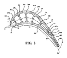
図1を参照すると、本発明の1つの態様において、翼アッセンブリ10が図示されている。本明細書で開示される冷却の概念は、固定ベーンと組み合わせて使用することができると理解されるが、翼アッセンブリ10は、翼、即ち回転可能なタービンブレード12を含むブレードアッセンブリであってよい。翼アッセンブリ10はガスタービンエンジンで使用するためのものである。当業者には公知であるように、ガスタービンエンジンは、圧縮機セクションと、燃焼器セクションと、タービンセクションとを有する(図示せず)。圧縮機セクションは圧縮機を含み、圧縮機は周囲の空気を圧縮し、少なくともその一部を燃焼器セクションへと搬送する。燃焼器セクションは1つ以上の燃焼器を含み、この燃焼器は、圧縮機セクションからの圧縮空気を燃料と混合し、混合物に点火して、このとき高温の作動ガスを形成する燃焼生成物が生じる。高温の作動ガスは、タービンセクションへと移動し、タービンセクションで作動ガスは1つ以上のタービン段を通過する。各タービン段は、1列の固定ベーンと、1列のタービンブレード12のような回転ブレードとを有している。
Referring to FIG. 1, in one aspect of the present invention, a
図1及び図2に示すように、タービンブレード12は、タービンロータ(図示せず)に連結された根元部14と、根元部14に固定されたプラットフォームアッセンブリ15とを有している。ブレード12は、プラットフォームアッセンブリ15に固定され、プラットフォームアッセンブリ15から半径方向外側に向かって延在している。ブレード12は、ほぼ凹面状の正圧面壁18と、ほぼ凸面状の負圧面壁20と、前縁22と、後縁24とを有している。前縁22は、(図2に3−3線で示す)翼弦方向で、後縁24から間を空けて位置している。正圧面壁18及び負圧面壁20は、翼幅方向又は半径方向RDで、プラットフォームアッセンブリ15から半径方向外側ブレード先端26まで半径方向外側に向かって延在しており、翼弦方向で前縁22と後縁24との間に延在している。
As shown in FIGS. 1 and 2, the
図2及び図3を参照すると、外壁16によりブレード12内にキャビティが画定されており、複数の翼幅方向構造体28は、外壁16と共に、プラットフォームアッセンブリ15から半径方向外側ブレード先端26まで半径方向に延在し、前縁22と後縁24との間に翼弦方向で延在する複数の冷却回路を画定している。特にこの冷却回路は、前縁冷却回路30と、中間区分冷却回路32と、後縁冷却回路34と、軸方向先端冷却回路56とを有している。
With reference to FIGS. 2 and 3, the
前縁冷却回路30は、前縁22に隣接して延在しており、部分的に外壁16と、図示した実施形態では実質的に中実の第1の壁を有する第1の翼幅方向構造体28aとによって画定されており、正圧面壁18と負圧面壁20との間、かつ前縁22と第1の翼幅方向構造体28aとの間に位置している。前縁冷却回路30は、プラットフォームアッセンブリ15から軸方向先端冷却回路56まで半径方向に延在している。前縁冷却回路30は、第1の翼幅方向構造体28aと第2の翼幅方向構造体28bとの間に画定された主前縁冷却通路30aを有している。第2の翼幅方向構造体28bは、第2の壁とインピンジメント通路30bとを有しており、インピンジメント通路30bは、主前縁冷却通路30aの上流に位置しており、前縁22を有する外壁16の一部と第2の翼幅方向構造体28bとの間に画定されている。第2の翼幅方向構造体28bを画定している第2の壁は、半径方向で間を空けて位置している複数のインピンジメント孔38を含んでおり、これらインピンジメント孔38により、主前縁冷却通路30aとインピンジメント通路30bとの間で流体連通が可能である。
The leading
主前縁冷却通路30aは、前縁プラットフォーム通路36と連通しており、前縁プラットフォーム通路36からの冷却空気流CFを受け取る。前縁プラットフォーム通路36は、根元部14とプラットフォームアッセンブリ15とを貫通して延在している。冷却空気流CFは、エンジンの圧縮機から抽気された冷却空気として供給されてよく、従来の形式でロータディスクへと通されてよい。冷却空気流CFは、主前縁冷却通路30aへと進入し、インピンジメント孔38内へ流れ込み、前縁22の内面にインピンジメント冷却を提供する。図3に示すように、第2の翼幅方向構造体28bは上流方向で僅かに傾いていてよく、これにより、第1及び第2の翼幅方向構造体28a,28bは、前縁冷却回路30の半径方向外側端部で接続され、全ての冷却空気流CFがインピンジメント通路30bに入るようにされる。より詳しく後述するように、前縁冷却回路30を画定する外壁16の一部は連続的であって、通常はブレード12の前縁22にフィルム冷却を提供するために使用されるフィルム冷却孔を含んでいない(図1参照)。
The main leading
引き続き図2及び図3を参照すると、後縁冷却回路34は、後縁24に隣接して延在し、部分的に外壁16と、第3の壁を有する第3の翼幅方向構造体28cとによって画定されており、正圧面壁18と負圧面壁20との間、かつ後縁24と第3の翼幅方向構造体28cとの間に位置している。後縁冷却回路34は、プラットフォームアッセンブリ15と、正圧面壁18と負圧面壁20との間に延在するキャビティフロア54との間で半径方向に延在している。図3に示すように、後縁冷却回路34は主後縁冷却通路42を有している。後縁冷却回路34はさらに、第1のリブ43及び第2のリブ45によって画定されており、部分的にキャビティフロア54によって画定されている。各リブ43,45はそれぞれ、インピンジメント孔43a又は調量孔45aを含んでいる。リブ43とリブ45との間には、第1及び第2の後縁インピンジメントキャビティ47,49が位置している。これらインピンジメントキャビティ47,49は主冷却通路42とインピンジメント孔43a,45aとに連通している。後縁放出スロット46は、後縁24を画定する外壁16の一部に位置している。第1及び第2のリブ43,45とその対応するインピンジメント孔43a,45aとは、後縁冷却回路34内でインピンジメント冷却を提供する。主後縁冷却通路42は、後縁プラットフォーム通路40と連通し、後縁プラットフォーム通路40からの冷却空気流CFを受け取る。後縁プラットフォーム通路40は、根元部14とプラットフォームアッセンブリ15とを貫通して延在している。第2の後縁インピンジメントキャビティ49を通る冷却空気流CFは、複数の後縁放出スロット46を通って放出され、後縁24にフィルム冷却を提供する。
With continued reference to FIGS. 2 and 3, the trailing edge cooling circuit 34 extends adjacent to the trailing
中間区分冷却回路32は、外壁16と、第1及び第3の翼幅方向構造体28a,28cと、第4及び第5の翼幅方向構造体28d,28eとによって画定されている。第4及び第5の翼幅方向構造体28d,28eは、第4及び第5の壁を有しており、正圧面壁18と負圧面壁20との間かつ第1及び第3の翼幅方向構造体28a,28cとの間に位置している。中間区分冷却回路32は、プラットフォームアッセンブリ15と軸方向先端冷却回路56との間で半径方向に延在し、部分的にキャビティフロア54によって画定されている。中間区分冷却回路32は、第1の通路32aと、中間通路32bと、最終通路32cとを含む前進流蛇行状冷却回路である。第3の翼幅方向構造体28cと第4の翼幅方向構造体28dとの間に画定された第1の通路32aは、中間区分プラットフォーム通路48と連通し、中間区分プラットフォーム通路48からの冷却空気流CFを受け取る。中間区分プラットフォーム通路48は、根元部14とプラットフォームアッセンブリ15とを貫通して延在している。第1の通路32aは、半径方向外側端部で、外側軸方向通路50を介して中間通路32bに接続されている。中間通路32bは、第4の翼幅方向構造体28dと第5の翼幅方向構造体28eとの間に画定されていて、半径方向内側端部で、内側軸方向通路52を介して最終通路32cに接続されている。最終通路32cは、第5の翼幅方向構造体28eと第1の翼幅方向構造体28aの間に画定されている。
The intermediate
軸方向先端冷却回路56は、外壁16によって正圧面壁18と負圧面壁20との間に画定されており、前縁22から後縁24へと連続的に延在している。軸方向先端冷却回路56は、半径方向外側端部で先端キャップ58によって画定されていて、半径方向内側端部で前縁冷却回路30と、中間区分冷却回路32と、キャビティフロア54とによって画定されている。インピンジメント通路30bの半径方向外側端部は前縁出口62を有しており、この前縁出口62は、軸方向先端冷却回路56の前方端に連通している。中間区分冷却回路32の第1の通路32aと中間通路32bの半径方向外側端部は、キャビティフロア54によって画定されており、最終通路32cの半径方向外側端部は、中間区分出口64を有しており、中間部分出口64は、軸方向先端冷却回路56の前方端に連通している。中間区分出口64は、前縁出口62に対して下流に位置している。
An axial
図3に示すように、冷却空気流CFは、前縁プラットフォーム通路36、中間区分プラットフォーム通路48、後縁プラットフォーム通路40に入り、前縁冷却回路30、中間区分冷却回路32、後縁冷却回路34内へそれぞれ流れる。後縁冷却空気流TEFは、主後縁冷却通路42へ進入し、インピンジメント孔43a,45aとリブ43,45の上方及び下方の開口とを介して第1及び第2の後縁インピンジメントキャビティ47,49内へと流れてから、後縁放出スロット46を通して放出されて、後縁24に冷却を提供する。前縁冷却空気流LEFは、主前縁冷却通路30aへと進入し、インピンジメント孔38を通ってインピンジメント通路30b内へと流れる。次いで、実質的に全ての前縁冷却空気流LEFが、前縁出口62を介して軸方向先端冷却回路56へと進入する。中間区分冷却空気流MSFは、第1の通路32aへと進入し、外側軸方向通路50を通って中間通路32b内へと流れる。次いで、実質的に全ての中間区分冷却空気流MSFが、内側軸方向通路52を介して最終通路32c内へと流れ込んだ後、中間区分出口64を通って軸方向先端冷却回路56へと進入する。インピンジメント通路30bから出た前縁冷却空気流LEFと中間区分冷却回路32の最終通路32cから出た中間区分冷却空気流MSFとは、軸方向先端冷却回路56で混合され、軸方向先端冷却空気流AFを形成する。軸方向先端冷却空気流AFは、翼弦方向で、前縁22から後縁24へと流れ、後縁24で軸方向先端放出スロット66を介してブレード12から放出される。
As shown in FIG. 3, the cooling air flow C F enters the leading edge platform passage 36, the middle
図3に示すように、キャビティフロア54はさらに、1つ以上の開口68を有していてよく、この開口は、中間区分冷却回路32及び/又は後縁冷却回路34を軸方向先端冷却回路56へと接続する。例えば図示したように、中間区分冷却回路32の第1の通路32aの半径方向外側端部近くのキャビティフロア54の部分は、第1の通路32aを軸方向先端冷却回路56に接続する開口68を有している。さらに、主後縁冷却通路42の半径方向外側端部近くのキャビティフロア54の部分は、主後縁冷却通路42を軸方向先端冷却回路56に接続する開口68を有している。
As shown in FIG. 3, the
図1及び図4を参照すると、タービンブレード12の半径方向外側ブレード先端26はさらに、外側スクィーラ先端キャビティ72を画定するように、先端キャップ58から半径方向外側に向かって延在し、タービンブレード12のほぼ全周にわたって延在するスクィーラ先端レール70を有していてよい。軸方向先端冷却回路56からスクィーラ先端キャビティ72内へと先端キャップ58を貫通して延在する複数の先端冷却孔74が設けられていてよい。軸方向先端冷却空気流AFの一部は、先端冷却孔74を通って流れてよく、先端キャップ58とスクィーラ先端レール70とに付加的な対流冷却を供給する。スクィーラ先端レール70は、軸方向先端冷却回路56からスクィーラ先端レール70を貫通して延在する複数のスクィーラ先端孔76を有していてよい。スクィーラ先端孔76は、図示した実施形態では、前縁22及び/又は正圧面壁18に隣接するスクィーラ先端レール70の部分を貫通して延在してよい。軸方向先端冷却空気流AFの一部は、スクィーラ先端レール70及び/又は正圧面壁18に冷却を供給するためにスクィーラ先端孔76を通って流れてよい。本発明のいくつかの態様では、図1及び図4に示すように、スクィーラ先端孔76を含むスクィーラ先端レール70の部分は、付加的に、スクィーラ先端レール70の外面に対して鋭角を成して位置する面取りされた面71を有していてよい。
With reference to FIGS. 1 and 4, the radially
図3に示した実施形態では、図4でより詳しく示したように、中間区分出口64はさらに、概して前縁冷却回路30と中間区分冷却回路32とに隣接して位置しており、軸方向先端冷却回路56内で翼弦方向に延在する隔壁60によって画定されてよい。隔壁60は例えば、第1及び第2の翼幅方向構造体28a,28bに連結されていてよく、かつ/又は第1及び第2の翼幅方向構造体28a,28bの延長部を有していてよい。隔壁60は、キャビティフロア54に対して半径方向外側に向かって間を空けて位置しており、先端キャップ58に対して半径方向内側に間を空けて位置している。隔壁60は、隔壁下方面61が、中間区分冷却回路32の最終通路32cを出る中間区分冷却空気流MSFに対してほぼ垂直又は横方向であるように、翼弦方向で延在している。
In the embodiment shown in FIG. 3, the intermediate section outlet 64 is further located generally adjacent to the leading
隔壁60は、前縁冷却空気流LEFと、それより高温の中間区分冷却空気流MSFとの間の相互作用による流れの閉塞を阻止している。隔壁60は、前縁冷却空気流LEFが隔壁60の上方を流れるように、前縁出口62に対して下流に位置している。先端キャップ58と共に、隔壁60は、前縁冷却空気流LEFを、軸方向先端冷却回路56を通って後縁24に向かうように軸方向に方向付ける。隔壁60は、中間区分出口64に対して上流に位置している。中間区分冷却空気流MSFは、軸方向先端冷却回路56を通って後縁24に向かうように、隔壁下方面61によって軸方向で再び方向付けられる。前縁冷却空気流LEFと中間区分冷却空気流MSFとは、ほぼ平行に軸方向先端冷却回路56の少なくとも一部を通って前縁22から後縁24へと流れて軸方向先端冷却空気流AFを形成し、この軸方向先端冷却空気流AFは、半径方向外側ブレード先端26とスクィーラ先端レール70とに付加的な冷却を提供する。本発明のいくつかの態様では、隔壁60は、軸方向先端冷却回路56の翼弦方向長さの40%まで、前縁冷却空気流LEFの分離した軸方向空気流を延長してよい。隔壁60が、軸方向先端冷却回路56の翼弦方向長さの約15%〜約25%の長さを有していてよいことが考えられる。
The
多くの従来のタービンブレードとは異なり、本発明によるタービンブレードは、タービンブレードの前縁における、又はタービンブレードの本体に沿ったシャワーヘッド状の配置(図1参照)における、フィルム冷却孔を含んでいない。特に原油のような重油を燃焼するタービンエンジンでは、運転中に、堆積物がこれらのフィルム冷却孔を詰まらせる恐れがある。十分な冷却の欠如により、前縁及び先端の焼損を含む、ブレードの深刻な損傷が生じる恐れがある。本明細書に開示されたような内部冷却が改良されたタービンブレードにより、フィルム冷却を伴わないか又は殆ど伴わずに、利用可能な冷却空気流をより効率的に利用することができる。 Unlike many conventional turbine blades, the turbine blade according to the present invention includes film cooling holes at the leading edge of the turbine blade or in a showerhead-like arrangement (see FIG. 1) along the body of the turbine blade. Not in. Especially in turbine engines that burn heavy oils such as crude oil, deposits can clog these film cooling holes during operation. The lack of sufficient cooling can cause severe blade damage, including burning of the leading edge and tip. Turbine blades with improved internal cooling as disclosed herein allow more efficient use of the available cooling air flow with little or no film cooling.
本発明の特定の実施の形態について例示及び説明してきたが、本発明の思想及び範囲から逸脱することなく様々なその他の変更及び改変をなし得ることは当業者に明らかであろう。従って、本発明の範囲内にある全てのこのような変更及び改変を、添付の請求項に網羅することが意図されている。 While particular embodiments of the present invention have been illustrated and described, it would be obvious to those skilled in the art that various other changes and modifications can be made without departing from the spirit and scope of the invention. Accordingly, it is intended to cover in the appended claims all such changes and modifications that are within the scope of this invention.
Claims (18)
前縁と、後縁と、正圧面壁と、負圧面壁とを画定する外壁と、先端を有する半径方向外側端部と、根元部に連結された半径方向内側端部とを有しており、前記前縁は、該前縁を貫通して延在するフィルム冷却孔を有しておらず、
前記外壁と共に前縁冷却回路を画定する構造体を有しており、前記前縁冷却回路は、前記前縁に隣接し、前記根元部から前記先端に向かって半径方向で延在し、かつ少なくとも1つの前縁冷却通路を有しており、
前記外壁と共に後縁冷却回路を画定する構造体を有しており、前記後縁冷却回路は、前記後縁に隣接し、前記根元部から前記先端に向かって半径方向で延在しており、
前記外壁と共に中間区分冷却回路を画定する構造体を有しており、前記中間区分冷却回路は、前記前縁冷却回路と前記後縁冷却回路との間に位置し、第1の通路と、中間通路と、最終通路とを含む前進流蛇行状冷却回路を画定し、かつ半径方向で前記根元部から前記先端に向かって延在しており、
前記外壁はさらに、軸方向先端冷却回路を画定しており、該軸方向先端冷却回路は、先端に隣接し、翼弦方向でほぼ連続的に延在しており、前記翼弦方向は、前記前縁から前記後縁へと延在しており、
前記前縁冷却回路と、前記中間区分冷却回路と、前記後縁冷却回路とはそれぞれ、前記根元部における冷却空気供給部から冷却空気を受け取り、前記前縁冷却回路と前記中間区分冷却回路はそれぞれ半径方向外側部分でさらに、少なくとも1つの出口を有しており、該出口は前記軸方向先端冷却回路に流体連通しており、これにより、前記前縁冷却回路から出る実質的に全ての前縁冷却空気流と、前記中間区分冷却回路から出る実質的に全ての中間区分冷却空気流とが、前記軸方向先端冷却回路へと方向付けられる、
タービンブレード。 A turbine blade, the turbine blade comprising:
An outer wall defining a leading edge, a trailing edge, a pressure surface wall, and a suction surface wall; a radially outer end having a tip; and a radially inner end coupled to a root portion. The leading edge does not have a film cooling hole extending through the leading edge;
A structure defining a leading edge cooling circuit with the outer wall, the leading edge cooling circuit adjacent to the leading edge, extending radially from the root toward the tip, and at least One leading edge cooling passage,
Having a structure defining a trailing edge cooling circuit with the outer wall, the trailing edge cooling circuit being adjacent to the trailing edge and extending radially from the root toward the tip;
A structure defining an intermediate section cooling circuit with the outer wall, wherein the intermediate section cooling circuit is located between the leading edge cooling circuit and the trailing edge cooling circuit; Defining a forward serpentine cooling circuit including a passage and a final passage and extending radially from the root toward the tip;
The outer wall further defines an axial tip cooling circuit, the axial tip cooling circuit adjacent to the tip and extending substantially continuously in the chord direction, the chord direction being Extending from the leading edge to the trailing edge,
The leading edge cooling circuit, the intermediate section cooling circuit, and the trailing edge cooling circuit each receive cooling air from a cooling air supply unit at the root, and the leading edge cooling circuit and the intermediate section cooling circuit are respectively The radial outer portion further includes at least one outlet, the outlet being in fluid communication with the axial tip cooling circuit, whereby substantially all leading edges exiting the leading edge cooling circuit. A cooling air stream and substantially all of the intermediate section cooling air stream exiting the intermediate section cooling circuit are directed to the axial tip cooling circuit;
Turbine blade.
前縁と、後縁と、正圧面壁と、負圧面壁とを画定する外壁と、先端を有する半径方向外側端部と、根元部に連結された半径方向内側端部とを有しており、前記前縁は、該前縁を貫通して延在するフィルム冷却孔を有しておらず、
前記外壁は、軸方向先端冷却回路を画定しており、該軸方向先端冷却回路は、先端に隣接し、翼弦方向で連続的に延在しており、前記翼弦方向は、前記前縁から前記後縁へと延在しており、
前記外壁と共に、前縁冷却空気流を供給するための前縁冷却回路を画定する構造体を有しており、前記前縁冷却回路は前記前縁に隣接し、半径方向で前記根元部から前記先端に向かって延在しており、前記前縁冷却回路はさらに第1の出口を有しており、該出口は前記軸方向先端冷却回路に流体連通しており、これにより、前記前縁冷却回路から出る実質的に全ての前縁冷却空気流は、前記軸方向先端冷却回路へと方向付けられ、
前記外壁と共に、後縁冷却回路を画定する構造体を有しており、前記後縁冷却回路は、前記後縁に隣接し、前記根元部から前記先端に向かって半径方向で延在しており、
前記外壁と共に、中間区分冷却空気流を供給するための中間区分冷却回路を画定する構造体を有しており、前記中間区分冷却回路は前記前縁冷却回路と前記後縁冷却回路との間に位置しており、前記中間区分冷却回路は第2の出口を有しており、該出口は前記軸方向先端冷却回路に流体連通しており、これにより、前記中間区分冷却回路から出る実質的に全ての中間区分冷却空気流は、前記軸方向先端冷却回路へと方向付けられ、
前記中間区分冷却回路と前記前縁冷却回路とにほぼ隣接する隔壁を有しており、該隔壁は前記翼弦方向に延在しており、前記隔壁は、隔壁下方面が、前記中間区分冷却回路から出る前記中間区分冷却空気流に対して実質的に横方向であるように配置されている、
タービンブレード。 A turbine blade, the turbine blade comprising:
An outer wall defining a leading edge, a trailing edge, a pressure surface wall, and a suction surface wall; a radially outer end having a tip; and a radially inner end coupled to a root portion. The leading edge does not have a film cooling hole extending through the leading edge;
The outer wall defines an axial tip cooling circuit, the axial tip cooling circuit is adjacent to the tip and extends continuously in the chord direction, the chord direction being the leading edge Extending to the trailing edge from
A structure defining a leading edge cooling circuit for supplying a leading edge cooling air flow with the outer wall, the leading edge cooling circuit being adjacent to the leading edge and radially from the root. Extending toward the tip, the leading edge cooling circuit further has a first outlet, the outlet being in fluid communication with the axial tip cooling circuit, whereby the leading edge cooling circuit Substantially all leading edge cooling air flow exiting the circuit is directed to the axial tip cooling circuit;
A structure defining a trailing edge cooling circuit is formed with the outer wall, and the trailing edge cooling circuit is adjacent to the trailing edge and extends radially from the root portion toward the tip. ,
A structure defining, with the outer wall, an intermediate section cooling circuit for supplying an intermediate section cooling air flow, the intermediate section cooling circuit between the leading edge cooling circuit and the trailing edge cooling circuit. And the intermediate section cooling circuit has a second outlet, the outlet being in fluid communication with the axial tip cooling circuit, thereby substantially exiting the intermediate section cooling circuit. All middle section cooling airflows are directed to the axial tip cooling circuit,
A partition substantially adjacent to the intermediate section cooling circuit and the leading edge cooling circuit, the partition extending in the chord direction, and the partition lower surface of the partition is the intermediate section cooling Arranged to be substantially transverse to the middle section cooling air flow exiting the circuit;
Turbine blade.
前記根元部を介して前記タービンブレードに冷却空気流を供給するステップと、
前記タービンブレードの前記前縁を冷却するために、前記冷却空気流の一部に前縁冷却回路を通過させるステップと、
前記冷却空気流の一部に、前記タービンブレードの前記前縁と前記後縁との間の中間区分冷却回路を通過させるステップと、
前記後縁を冷却し、前記外壁における前記複数の後縁出口通路から出るために、前記冷却空気流の一部に後縁冷却回路を通過させるステップと、
前記前縁冷却回路を出る実質的に全ての前縁冷却空気流と、前記中間区分冷却回路を出る実質的に全ての中間区分冷却空気流とを軸方向先端冷却回路へと方向付けて、軸方向先端冷却空気流を発生させるステップであって、前記軸方向先端冷却回路は、前記先端に隣接し翼弦方向で連続的に延在しており、前記翼弦方向は、前記前縁から前記後縁へと延在しているステップと、
前記先端に冷却を提供するために、前記軸方向先端冷却空気流に翼弦方向で前記軸方向先端冷却回路内を軸方向で通過させるステップと、
を含む方法。 A method of cooling a turbine blade used in a gas turbine engine, the turbine blade defining a leading edge, a trailing edge with a plurality of trailing edge outlet passages, a pressure surface wall, and a suction surface wall. An outer wall, a radially outer end having a tip, and a radially inner end connected to a root, the leading edge having a film cooling hole penetrating the leading edge. The method is not
Supplying a cooling air flow to the turbine blade through the root;
Passing a leading edge cooling circuit through a portion of the cooling air flow to cool the leading edge of the turbine blade;
Passing a portion of the cooling air flow through an intermediate section cooling circuit between the leading edge and the trailing edge of the turbine blade;
Passing a trailing edge cooling circuit through a portion of the cooling air flow to cool the trailing edge and exit from the plurality of trailing edge outlet passages in the outer wall;
Directing substantially all leading edge cooling airflow exiting the leading edge cooling circuit and substantially all intermediate section cooling airflow exiting the intermediate section cooling circuit to an axial tip cooling circuit, Generating a directional tip cooling air flow, wherein the axial tip cooling circuit extends continuously in the chord direction adjacent to the tip, the chord direction extending from the leading edge to the tip A step extending to the trailing edge;
Passing the axial tip cooling air stream axially through the axial tip cooling circuit in the chord direction to provide cooling to the tip; and
Including methods.
Applications Claiming Priority (1)
| Application Number | Priority Date | Filing Date | Title |
|---|---|---|---|
| PCT/US2014/064944 WO2016076834A1 (en) | 2014-11-11 | 2014-11-11 | Turbine blade with axial tip cooling circuit |
Publications (2)
| Publication Number | Publication Date |
|---|---|
| JP2018500491A true JP2018500491A (en) | 2018-01-11 |
| JP6434145B2 JP6434145B2 (en) | 2018-12-05 |
Family
ID=51999546
Family Applications (1)
| Application Number | Title | Priority Date | Filing Date |
|---|---|---|---|
| JP2017525580A Expired - Fee Related JP6434145B2 (en) | 2014-11-11 | 2014-11-11 | Turbine blade with axial tip cooling circuit |
Country Status (5)
| Country | Link |
|---|---|
| US (1) | US20180298763A1 (en) |
| EP (1) | EP3218582A1 (en) |
| JP (1) | JP6434145B2 (en) |
| CN (1) | CN107109949A (en) |
| WO (1) | WO2016076834A1 (en) |
Families Citing this family (15)
| Publication number | Priority date | Publication date | Assignee | Title |
|---|---|---|---|---|
| US10563518B2 (en) * | 2016-02-15 | 2020-02-18 | General Electric Company | Gas turbine engine trailing edge ejection holes |
| EP3354850A1 (en) * | 2017-01-31 | 2018-08-01 | Siemens Aktiengesellschaft | A turbine blade or a turbine vane for a gas turbine |
| US10370982B2 (en) * | 2017-02-03 | 2019-08-06 | DOOSAN Heavy Industries Construction Co., LTD | Double shelf squealer tip with impingement cooling of serpentine cooled turbine blades |
| US11021967B2 (en) * | 2017-04-03 | 2021-06-01 | General Electric Company | Turbine engine component with a core tie hole |
| US10787932B2 (en) * | 2018-07-13 | 2020-09-29 | Honeywell International Inc. | Turbine blade with dust tolerant cooling system |
| US10961854B2 (en) * | 2018-09-12 | 2021-03-30 | Raytheon Technologies Corporation | Dirt funnel squealer purges |
| US10731478B2 (en) * | 2018-12-12 | 2020-08-04 | Solar Turbines Incorporated | Turbine blade with a coupled serpentine channel |
| GB201900961D0 (en) * | 2019-01-24 | 2019-03-13 | Rolls Royce Plc | Fan blade |
| US11118462B2 (en) * | 2019-01-24 | 2021-09-14 | Pratt & Whitney Canada Corp. | Blade tip pocket rib |
| EP3832069A1 (en) * | 2019-12-06 | 2021-06-09 | Siemens Aktiengesellschaft | Turbine blade for a stationary gas turbine |
| CN111677557B (en) * | 2020-06-08 | 2021-10-26 | 清华大学 | Turbine guide blade and turbo machine with same |
| US11371359B2 (en) | 2020-11-26 | 2022-06-28 | Pratt & Whitney Canada Corp. | Turbine blade for a gas turbine engine |
| FR3117389B1 (en) * | 2020-12-10 | 2022-11-04 | Safran | High pressure turbine blade comprising a cavity under a bath |
| CN114215607A (en) * | 2021-11-29 | 2022-03-22 | 西安交通大学 | Turbine blade leading edge rotational flow cooling structure |
| US11920496B1 (en) | 2022-11-10 | 2024-03-05 | Doosan Enerbility Co., Ltd. | Airfoil, and turbine blade and gas turbine including the same |
Citations (5)
| Publication number | Priority date | Publication date | Assignee | Title |
|---|---|---|---|---|
| JPH0223202A (en) * | 1988-04-25 | 1990-01-25 | United Technol Corp <Utc> | Cooling device for turbine blade |
| JPH06137102A (en) * | 1992-10-26 | 1994-05-17 | Mitsubishi Heavy Ind Ltd | Hollow moving blade of gas turbine |
| JPH11247608A (en) * | 1997-12-17 | 1999-09-14 | United Technol Corp <Utc> | Turbine blade |
| JP2011163123A (en) * | 2010-02-04 | 2011-08-25 | Ihi Corp | Turbine moving blade |
| US20140093387A1 (en) * | 2012-09-28 | 2014-04-03 | Solar Turbines Incorporated | Method of manufacturing a cooled turbine blade with dense cooling fin array |
Family Cites Families (29)
| Publication number | Priority date | Publication date | Assignee | Title |
|---|---|---|---|---|
| US4514144A (en) * | 1983-06-20 | 1985-04-30 | General Electric Company | Angled turbulence promoter |
| JPS62228603A (en) * | 1986-03-31 | 1987-10-07 | Toshiba Corp | Gas turbine blade |
| US4753575A (en) * | 1987-08-06 | 1988-06-28 | United Technologies Corporation | Airfoil with nested cooling channels |
| US4820122A (en) * | 1988-04-25 | 1989-04-11 | United Technologies Corporation | Dirt removal means for air cooled blades |
| US4820123A (en) * | 1988-04-25 | 1989-04-11 | United Technologies Corporation | Dirt removal means for air cooled blades |
| US5183385A (en) * | 1990-11-19 | 1993-02-02 | General Electric Company | Turbine blade squealer tip having air cooling holes contiguous with tip interior wall surface |
| US5156526A (en) * | 1990-12-18 | 1992-10-20 | General Electric Company | Rotation enhanced rotor blade cooling using a single row of coolant passageways |
| US5660524A (en) * | 1992-07-13 | 1997-08-26 | General Electric Company | Airfoil blade having a serpentine cooling circuit and impingement cooling |
| US5403159A (en) * | 1992-11-30 | 1995-04-04 | United Technoligies Corporation | Coolable airfoil structure |
| US5348446A (en) * | 1993-04-28 | 1994-09-20 | General Electric Company | Bimetallic turbine airfoil |
| US5387086A (en) * | 1993-07-19 | 1995-02-07 | General Electric Company | Gas turbine blade with improved cooling |
| US5387085A (en) * | 1994-01-07 | 1995-02-07 | General Electric Company | Turbine blade composite cooling circuit |
| US5902093A (en) * | 1997-08-22 | 1999-05-11 | General Electric Company | Crack arresting rotor blade |
| US6126396A (en) * | 1998-12-09 | 2000-10-03 | General Electric Company | AFT flowing serpentine airfoil cooling circuit with side wall impingement cooling chambers |
| US6168381B1 (en) * | 1999-06-29 | 2001-01-02 | General Electric Company | Airfoil isolated leading edge cooling |
| US6431832B1 (en) * | 2000-10-12 | 2002-08-13 | Solar Turbines Incorporated | Gas turbine engine airfoils with improved cooling |
| US7104757B2 (en) * | 2003-07-29 | 2006-09-12 | Siemens Aktiengesellschaft | Cooled turbine blade |
| US20050265839A1 (en) * | 2004-05-27 | 2005-12-01 | United Technologies Corporation | Cooled rotor blade |
| US20050265840A1 (en) * | 2004-05-27 | 2005-12-01 | Levine Jeffrey R | Cooled rotor blade with leading edge impingement cooling |
| US7186082B2 (en) * | 2004-05-27 | 2007-03-06 | United Technologies Corporation | Cooled rotor blade and method for cooling a rotor blade |
| US7249934B2 (en) * | 2005-08-31 | 2007-07-31 | General Electric Company | Pattern cooled turbine airfoil |
| US8083486B1 (en) * | 2009-05-15 | 2011-12-27 | Florida Turbine Technologies, Inc. | Turbine blade with cooling flow modulation |
| US8231350B1 (en) * | 2009-07-09 | 2012-07-31 | Florida Turbine Technologies, Inc. | Turbine rotor blade |
| US9022736B2 (en) * | 2011-02-15 | 2015-05-05 | Siemens Energy, Inc. | Integrated axial and tangential serpentine cooling circuit in a turbine airfoil |
| US9546554B2 (en) * | 2012-09-27 | 2017-01-17 | Honeywell International Inc. | Gas turbine engine components with blade tip cooling |
| US9206695B2 (en) * | 2012-09-28 | 2015-12-08 | Solar Turbines Incorporated | Cooled turbine blade with trailing edge flow metering |
| US9447692B1 (en) * | 2012-11-28 | 2016-09-20 | S&J Design Llc | Turbine rotor blade with tip cooling |
| US20150204197A1 (en) * | 2014-01-23 | 2015-07-23 | Siemens Aktiengesellschaft | Airfoil leading edge chamber cooling with angled impingement |
| US10119404B2 (en) * | 2014-10-15 | 2018-11-06 | Honeywell International Inc. | Gas turbine engines with improved leading edge airfoil cooling |
-
2014
- 2014-11-11 EP EP14805438.0A patent/EP3218582A1/en not_active Withdrawn
- 2014-11-11 WO PCT/US2014/064944 patent/WO2016076834A1/en active Application Filing
- 2014-11-11 US US15/525,820 patent/US20180298763A1/en not_active Abandoned
- 2014-11-11 CN CN201480084547.2A patent/CN107109949A/en active Pending
- 2014-11-11 JP JP2017525580A patent/JP6434145B2/en not_active Expired - Fee Related
Patent Citations (5)
| Publication number | Priority date | Publication date | Assignee | Title |
|---|---|---|---|---|
| JPH0223202A (en) * | 1988-04-25 | 1990-01-25 | United Technol Corp <Utc> | Cooling device for turbine blade |
| JPH06137102A (en) * | 1992-10-26 | 1994-05-17 | Mitsubishi Heavy Ind Ltd | Hollow moving blade of gas turbine |
| JPH11247608A (en) * | 1997-12-17 | 1999-09-14 | United Technol Corp <Utc> | Turbine blade |
| JP2011163123A (en) * | 2010-02-04 | 2011-08-25 | Ihi Corp | Turbine moving blade |
| US20140093387A1 (en) * | 2012-09-28 | 2014-04-03 | Solar Turbines Incorporated | Method of manufacturing a cooled turbine blade with dense cooling fin array |
Also Published As
| Publication number | Publication date |
|---|---|
| WO2016076834A1 (en) | 2016-05-19 |
| US20180298763A1 (en) | 2018-10-18 |
| JP6434145B2 (en) | 2018-12-05 |
| EP3218582A1 (en) | 2017-09-20 |
| CN107109949A (en) | 2017-08-29 |
Similar Documents
| Publication | Publication Date | Title |
|---|---|---|
| JP6434145B2 (en) | Turbine blade with axial tip cooling circuit | |
| US8920123B2 (en) | Turbine blade with integrated serpentine and axial tip cooling circuits | |
| JP5442160B2 (en) | Wing having a built-up surface portion in which a cooling passage is embedded | |
| US7607891B2 (en) | Turbine component with tip flagged pedestal cooling | |
| US8202054B2 (en) | Blade for a gas turbine engine | |
| JP6506514B2 (en) | Method and system for cooling a moving wing angel wing | |
| EP1959097B1 (en) | Impingement skin core cooling for gas turbine engine blade | |
| EP2885504B1 (en) | Airfoil and corresponding gas turbine engine | |
| US8985949B2 (en) | Cooling system including wavy cooling chamber in a trailing edge portion of an airfoil assembly | |
| US20170101870A1 (en) | Cooling holes of turbine | |
| CN108868898A (en) | The device and method of airfoil for cooling turbine engines | |
| US11549377B2 (en) | Airfoil with cooling hole | |
| US10697306B2 (en) | Gas turbine airfoil including integrated leading edge and tip cooling fluid passage and core structure used for forming such an airfoil | |
| US10794194B2 (en) | Staggered core printout | |
| JP2017534791A5 (en) | ||
| CN110159355A (en) | Engine component with cooling hole | |
| US11293288B2 (en) | Turbine blade with tip trench | |
| EP3266983B1 (en) | Cooling system for an airfoil of a gas powered turbine | |
| US10494929B2 (en) | Cooled airfoil structure | |
| JP2021046853A (en) | Turbine blade and gas turbine having the same |
Legal Events
| Date | Code | Title | Description |
|---|---|---|---|
| A131 | Notification of reasons for refusal |
Free format text: JAPANESE INTERMEDIATE CODE: A131 Effective date: 20180521 |
|
| A977 | Report on retrieval |
Free format text: JAPANESE INTERMEDIATE CODE: A971007 Effective date: 20180517 |
|
| A521 | Request for written amendment filed |
Free format text: JAPANESE INTERMEDIATE CODE: A523 Effective date: 20180820 |
|
| TRDD | Decision of grant or rejection written | ||
| A01 | Written decision to grant a patent or to grant a registration (utility model) |
Free format text: JAPANESE INTERMEDIATE CODE: A01 Effective date: 20181029 |
|
| A61 | First payment of annual fees (during grant procedure) |
Free format text: JAPANESE INTERMEDIATE CODE: A61 Effective date: 20181107 |
|
| R150 | Certificate of patent or registration of utility model |
Ref document number: 6434145 Country of ref document: JP Free format text: JAPANESE INTERMEDIATE CODE: R150 |
|
| LAPS | Cancellation because of no payment of annual fees |