JP2018200410A - Medium and method for manufacturing medium - Google Patents
Medium and method for manufacturing medium Download PDFInfo
- Publication number
- JP2018200410A JP2018200410A JP2017105294A JP2017105294A JP2018200410A JP 2018200410 A JP2018200410 A JP 2018200410A JP 2017105294 A JP2017105294 A JP 2017105294A JP 2017105294 A JP2017105294 A JP 2017105294A JP 2018200410 A JP2018200410 A JP 2018200410A
- Authority
- JP
- Japan
- Prior art keywords
- layer
- retroreflective sheet
- medium
- lens
- lens layer
- Prior art date
- Legal status (The legal status is an assumption and is not a legal conclusion. Google has not performed a legal analysis and makes no representation as to the accuracy of the status listed.)
- Pending
Links
- 238000000034 method Methods 0.000 title claims abstract description 20
- 238000004519 manufacturing process Methods 0.000 title abstract description 19
- 238000007599 discharging Methods 0.000 claims description 2
- 230000001678 irradiating effect Effects 0.000 claims description 2
- 238000004040 coloring Methods 0.000 claims 2
- 239000010410 layer Substances 0.000 description 130
- 239000000976 ink Substances 0.000 description 63
- 238000010586 diagram Methods 0.000 description 20
- 230000004048 modification Effects 0.000 description 5
- 238000012986 modification Methods 0.000 description 5
- 239000002344 surface layer Substances 0.000 description 5
- 239000000463 material Substances 0.000 description 4
- 230000000740 bleeding effect Effects 0.000 description 2
- 239000000470 constituent Substances 0.000 description 2
- 238000002834 transmittance Methods 0.000 description 2
- 239000011324 bead Substances 0.000 description 1
- 230000015572 biosynthetic process Effects 0.000 description 1
- 239000011248 coating agent Substances 0.000 description 1
- 238000000576 coating method Methods 0.000 description 1
- 239000003086 colorant Substances 0.000 description 1
- 230000003111 delayed effect Effects 0.000 description 1
- 230000000694 effects Effects 0.000 description 1
- 239000004744 fabric Substances 0.000 description 1
- 239000011521 glass Substances 0.000 description 1
- 239000011347 resin Substances 0.000 description 1
- 229920005989 resin Polymers 0.000 description 1
- 230000000630 rising effect Effects 0.000 description 1
- 230000035807 sensation Effects 0.000 description 1
- 239000007787 solid Substances 0.000 description 1
- 239000000758 substrate Substances 0.000 description 1
- XLYOFNOQVPJJNP-UHFFFAOYSA-N water Substances O XLYOFNOQVPJJNP-UHFFFAOYSA-N 0.000 description 1
Images


Abstract
Description
本発明は、メディア及びメディアの製造方法に関する。 The present invention relates to a medium and a method for manufacturing the medium.
従来、再帰反射シート上に画像等を形成することにより、画像の視認性を確保する画像シートが知られている(例えば、特許文献1等参照)。 2. Description of the Related Art Conventionally, an image sheet that secures image visibility by forming an image or the like on a retroreflective sheet is known (see, for example, Patent Document 1).
特許文献1に記載の画像シートは、例えば画像を形成した透明フィルムを再帰反射シート上に貼り合せた構成であるため、全体的に単調なデザインとなる。近年、このような再帰反射シート上に画像等を形成するメディアにおいては、視認性を向上させつつ、デザイン性にも優れた構成とすることが求められている。 Since the image sheet described in Patent Document 1 has a configuration in which, for example, a transparent film on which an image is formed is bonded onto a retroreflective sheet, the image sheet has a monotonous design as a whole. In recent years, a medium for forming an image or the like on such a retroreflective sheet has been required to have a structure with excellent design while improving visibility.
本発明は、上記に鑑みてなされたものであり、視認性の向上を図ることができ、デザイン性にも優れたメディア及びメディアの製造方法を提供することを目的とする。 The present invention has been made in view of the above, and an object of the present invention is to provide a medium that can improve visibility and is excellent in design and a method for manufacturing the medium.
本発明に係るメディアは、入射光を再帰反射する複数の球状体を有する再帰反射シートと、前記再帰反射シート上に複数の前記球状体に跨るように形成された凸状のレンズ層とを備える。 A medium according to the present invention includes a retroreflective sheet having a plurality of spherical bodies that retroreflect incident light, and a convex lens layer formed on the retroreflective sheet so as to straddle the plurality of spherical bodies. .
この構成によれば、再帰反射シートが露出した領域では、当該再帰反射シートに光が照射される方向と同一方向から見た場合には、再帰反射により再帰反射シートの表面を視認可能となる。一方、レンズ層が設けられる領域では、当該レンズ層により、再帰反射シートが露出した領域とは異なる反射態様となる。そのため、レンズ層が設けられる領域と再帰反射シートが露出した領域とでコントラストが生じ、当該コントラストによる画像が視認可能となる。これにより、視認性の向上を図ることができ、デザイン性にも優れたメディアを提供することができる。 According to this configuration, in the region where the retroreflective sheet is exposed, the surface of the retroreflective sheet can be visually recognized by retroreflection when viewed from the same direction as the direction in which the retroreflective sheet is irradiated with light. On the other hand, in the region where the lens layer is provided, the lens layer has a reflection mode different from the region where the retroreflective sheet is exposed. Therefore, a contrast is generated between the region where the lens layer is provided and the region where the retroreflective sheet is exposed, and an image based on the contrast becomes visible. As a result, it is possible to improve visibility and to provide media with excellent design.
上記のメディアは、前記再帰反射シートの表面上に配置され、前記再帰反射シート上を着色する着色層を更に備え、前記レンズ層は、前記着色層上に配置されてもよい。 The medium may further include a colored layer that is disposed on a surface of the retroreflective sheet and colors the retroreflective sheet, and the lens layer may be disposed on the colored layer.
この構成によれば、着色層が設けられるため、より視認性が高められると共に、より多様な見え方を提供することができる。 According to this configuration, since the colored layer is provided, the visibility can be further improved and more various appearances can be provided.
上記のメディアにおいて、前記着色層は、光透過性を有してもよい。 In the above medium, the colored layer may have light transmittance.
この構成によれば、着色層が光透過性を有するため、より視認性が高められると共に、より多様な見え方を提供することができる。 According to this configuration, since the colored layer has light transmittance, the visibility can be further improved and more various appearances can be provided.
上記のメディアにおいて、前記レンズ層は、凸状の頂上部分からエッジ部分にかけてなだらかに湾曲した形状のレンズ面を有してもよい。 In the above media, the lens layer may have a lens surface that is gently curved from a convex top portion to an edge portion.
この構成によれば、レンズ層が、頂上部分からエッジ部分がなだらかになるように湾曲した形状のレンズ面を有するため、レンズ層において光の干渉を効果的に生じさせることができる。 According to this configuration, since the lens layer has a curved lens surface so that the edge portion becomes gentle from the top portion, light interference can be effectively generated in the lens layer.
上記のメディアにおいて、前記レンズ部は、平面視において縞状又は市松模様状に配置されてもよい。 In the above medium, the lens unit may be arranged in a striped pattern or a checkered pattern in a plan view.
この構成によれば、視認性が高く、多様な見え方を提供可能であり、かつデザイン性にも優れた画像を提供可能である。 According to this configuration, it is possible to provide an image that has high visibility, can provide various appearances, and is excellent in design.
本発明に係るメディアの製造方法は、紫外線硬化インクを含むクリアインクを再帰反射シート上にインクジェット方式によって吐出する吐出工程と、前記吐出した前記クリアインクに対して所定時間を空けて紫外線を複数回に分けて照射することで前記クリアインクを徐々に硬化させてレンズ層を形成する硬化工程とを含む。 The method for manufacturing a medium according to the present invention includes a discharge step of discharging a clear ink containing an ultraviolet curable ink onto a retroreflective sheet by an ink jet method, and a plurality of times of ultraviolet light with a predetermined time interval with respect to the discharged clear ink. And a curing step of gradually curing the clear ink by irradiation and forming a lens layer.
この構成によれば、再帰反射シート上に吐出したクリアインクに対して、所定時間を空けて紫外線を複数回に分けて照射することでクリアインクを徐々に硬化させてレンズ層を形成することにより、レンズ層の形状を、頂上部分からエッジ部分にかけてなだらかに湾曲した形状とすることができる。これにより、光の干渉を効果的に生じさせることができるレンズ層を形成できる。 According to this configuration, the clear ink discharged onto the retroreflective sheet is irradiated with ultraviolet rays in a plurality of times with a predetermined time interval, whereby the clear ink is gradually cured to form a lens layer. The shape of the lens layer can be a gently curved shape from the top portion to the edge portion. Thereby, a lens layer capable of effectively causing light interference can be formed.
本発明によれば、視認性の向上を図ることができ、デザイン性にも優れたメディア及びメディアの製造方法を提供することができる。 ADVANTAGE OF THE INVENTION According to this invention, the improvement of visibility can be aimed at and the manufacturing method of the medium excellent also in the design property can be provided.
以下に、本発明に係る実施形態を図面に基づいて詳細に説明する。なお、この実施形態によりこの発明が限定されるものではない。また、下記実施形態における構成要素には、当業者が置換可能かつ容易なもの、あるいは実質的に同一のものが含まれる。さらに、以下に記載した構成要素は適宜組み合わせることが可能であり、また、実施形態が複数ある場合には、各実施形態を組み合わせることも可能である。 Embodiments according to the present invention will be described below in detail with reference to the drawings. In addition, this invention is not limited by this embodiment. In addition, constituent elements in the following embodiments include those that can be easily replaced by those skilled in the art or those that are substantially the same. Furthermore, the constituent elements described below can be appropriately combined, and when there are a plurality of embodiments, the embodiments can be combined.
[第1実施形態]
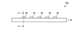
図1は、第1実施形態に係るメディア100の一例を示す図である。図2は、図1におけるA−A断面に沿った構成を示す図である。図1及び図2に示すように、メディア100は、再帰反射シート10と、レンズ層20とを備える。
[First Embodiment]
FIG. 1 is a diagram illustrating an example of a
再帰反射シート10は、基材11と、複数の球状体12と、表面層13とを有する。基材11は、紙、布帛、フィルム等を用いることができる。複数の球状体12は、基材11上に配置される。球状体12は、入射光を再帰反射する。球状体12は、基材11上に縦横に配置される。各球状体12の直径R1は、例えば40μm程度となっている。球状体12としては、例えばガラスビーズ等が用いられる。表面層13は、複数の球状体12上に当該複数の球状体12を覆うように配置される。表面層13は、例えば透明な樹脂等を用いて形成される。
The
レンズ層20は、再帰反射シート10上に例えば複数配置される。レンズ層20は、再帰反射シート10上に所定のパターンで配置される。レンズ層20は、例えば凸状であり、再帰反射シート10の複数の球状体12に跨るように形成される。レンズ層20の平面視における形状としては、例えば円形、楕円形、多角形(三角形、四角形等)等が挙げられる。レンズ層20のうち平面視において最小幅となる部分の寸法R2は、例えば200μm〜3mm程度の寸法を有する。このように、レンズ層20は、複数の球状体12に十分に跨ることが可能な寸法に形成される。
For example, a plurality of
レンズ層20は、レンズ面21を有する。レンズ面21は、再帰反射シート10から盛り上がった状態で形成される。レンズ面21は、頂上部分22と、エッジ部分23とを有する。頂上部分22は、再帰反射シート10に対して、当該再帰反射シートの法線方向について最も高さ位置が高い箇所である。エッジ部分23は、再帰反射シート10との境界部分であり、平面視においてレンズ層20の外形を象る部分である。レンズ面21は、頂上部分22からエッジ部分23にかけてなだらかに湾曲した形状を有する。
The
レンズ層20は、紫外線硬化インクを用いて形成され、透明な層となっている。レンズ層20は、頂上部分22までの高さ(厚さ)が例えば40μm以上となっている。レンズ層20に用いられる紫外線硬化インクは、紫外線が照射されることで完全硬化するインクである。紫外線硬化インクとしては、例えば、ミマキエンジニアリング製の「LH−100 Clear」又は桜井株式会社製の「LF−350 Clear」が用いられる。これらの紫外線硬化インクを用いることにより、例えば可撓性を有する再帰反射シート10上にレンズ層20を形成した場合に、再帰反射シート10を曲げた場合であっても再帰反射シート10の変形に追従して変形可能となる。
The
本実施形態に係るメディア100は、再帰反射シート10が露出した領域では、当該再帰反射シート10に入射する光L1が再帰反射され、光L1の入射方向と同一方向から見た場合には、再帰反射により再帰反射シート10の表面が視認可能となる。一方、レンズ層20が設けられる領域では、当該レンズ層20により、再帰反射シート10が露出した領域とは異なる反射態様となる。そのため、レンズ層20が設けられる領域と再帰反射シート10が露出した領域とでコントラストが生じ、当該コントラストによる画像が視認可能となる。これにより、視認性の向上を図ることができ、デザイン性にも優れたメディア100を提供することができる。
In the medium 100 according to the present embodiment, in the region where the
また、レンズ層20においては、当該レンズ層20に入射する一部の光L2がレンズ層20のレンズ面21で反射され、他の一部の光L3がレンズ層20内に進行し再帰反射シート10により反射されてレンズ層20のレンズ面21から出射される。このため、レンズ面21で反射される光L2と、再帰反射シート10で反射されてレンズ面21から出射される光L3とが干渉する場合がある。この場合には、レンズ層20を見る方向に応じてあたかも水面に浮かぶ油膜を見るように見え方が変化することになる。
In the
また、例えば夜間等の外光が十分に照射されない状態において、一方向から再帰反射シート10及びレンズ層20に光を照射して当該光の照射方向からメディア100を見た場合、メディア100から離れた位置から見ると、再帰反射シート10の全面が再帰反射しているように視認される。また、メディア100に近づいた位置から見ると、レンズ層20が設けられる領域と再帰反射シート10が露出した領域との間のコントラストが視認される。このように、メディア100は、多様な見え方を提供可能となる。
Further, when the external reflection light 10 and the
[第2実施形態]
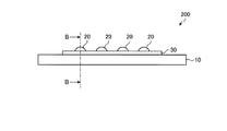
図3は、第2実施形態に係るメディア200の一例を示す図である。図4は、図3におけるB−B断面に沿った構成を示す図である。図3及び図4に示すように、メディア200は、再帰反射シート10と、レンズ層20と、着色層30とを備える。つまり、本実施形態に係るメディア200は、再帰反射シート10とレンズ層20との間に、着色層30が設けられる。再帰反射シート10の構成については、第1実施形態と同様である。また、本実施形態において、レンズ層20は、着色層30上に、所定のパターンで複数配置される。
[Second Embodiment]
FIG. 3 is a diagram illustrating an example of the medium 200 according to the second embodiment. FIG. 4 is a diagram showing a configuration along the BB cross section in FIG. 3. As shown in FIGS. 3 and 4, the medium 200 includes a
着色層30は、紫外線硬化型のカラーインクを用いて形成される画像層である。着色層30は、再帰反射シート10の表面層13上に形成されている。本実施形態において、着色層30は、光透過性を有するが、これに限定されず、光透過性を有しない構成であってもよい。着色層30において形成される画像は、例えば、文字及び図柄等を組み合わせたもの、または、所定の領域を塗りつぶしたベタ塗り等を含むものである。着色層30に用いられる紫外線硬化型のカラーインクは、紫外線が照射されることで完全硬化するインクである。なお、完全硬化とは、紫外線硬化型のカラーインクに紫外線が照射されることで架橋した状態となることである。着色層30に用いられる紫外線硬化型のカラーインクとしては、例えば、例えば、ミマキエンジニアリング製の「LH−100」または桜井株式会社製の「LF−350」が用いられる。
The
本実施形態に係るメディア200は、再帰反射シート10が露出した領域では、当該再帰反射シート10に入射する光が再帰反射され、光の入射方向と同一方向から見た場合には、再帰反射により再帰反射シート10の表面が視認可能となる。また、着色層30が露出した領域では、当該着色層30に入射する光L4が着色層30を透過し、再帰反射シート10で再帰反射され、着色層30を透過して入射方向と反対方向に進行する。このため、光の入射方向と同一方向から見た場合には、着色層30を透過した着色光が視認可能となる。
In the medium 200 according to the present embodiment, in the region where the
また、レンズ層20が設けられる領域では、当該レンズ層20により、着色層30が露出した領域とは異なる反射態様となる。そのため、レンズ層20が設けられる領域と着色層30が露出した領域とでコントラストが生じ、当該コントラストによる画像が視認可能となる。これにより、着色層30による色感と相まって、視認性の向上を図ることができ、デザイン性にも優れたメディア100を提供することができる。
Further, in the region where the
また、レンズ層20においては、当該レンズ層20に入射する一部の光L5がレンズ層20のレンズ面21で反射される。また、他の一部の光L6がレンズ層20内に進行し、着色層30を透過して再帰反射シート10により再帰反射され、着色層30を戻ってレンズ層20のレンズ面21から出射される。このため、これらの光L5及び光L6により、レンズ層20を見る方向によって見え方が変化する。これにより、視認性の向上を図ることができ、デザイン性にも優れたメディア200を提供することができる。
In the
また、例えば夜間等の外光が十分に照射されない状態において、一方向から再帰反射シート10及びレンズ層20に光を照射して当該光の照射方向からメディア200を見た場合、メディア200から離れた位置から見ると、再帰反射シート10の全面が再帰反射しているように視認される。また、メディア200に近づいた位置から見ると、レンズ層20が設けられる領域と、着色層30が露出した領域と、再帰反射シート10が露出した領域との間のコントラストが視認される。このように、メディア200は、多様な見え方を提供可能となる。
Further, when the external reflection light 10 and the
[第3実施形態]
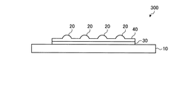
図5は、第3実施形態に係るメディア300の一例を示す図である。図5に示すように、メディア300は、再帰反射シート10と、レンズ層20と、着色層30と、透明層40とを備える。本実施形態に係るメディア300は、再帰反射シート10とレンズ層20との間に、着色層30及び透明層40が設けられる。再帰反射シート10、着色層30の構成については、第2実施形態と同様である。また、本実施形態において、レンズ層20は、透明層40上に、所定のパターンで複数配置される。
[Third Embodiment]
FIG. 5 is a diagram illustrating an example of the medium 300 according to the third embodiment. As shown in FIG. 5, the medium 300 includes a
透明層40は、着色層30上を覆うように配置され、着色層30を保護している。透明層40は、レンズ層20と同様の紫外線硬化インクを用いて形成されている。したがって、透明層40に用いられる紫外線硬化インクは、紫外線が照射されることで完全硬化するインクであり、例えば、ミマキエンジニアリング製の「LH−100 Clear」又は桜井株式会社製の「LF−350 Clear」が用いられる。
The
したがって、本実施形態に係るメディア300は、透明層40の表面に複数の凸部が形成された状態となっており、当該凸部がレンズ層20となっている。このため、着色層30を確実に保護することができる。また、透明層40の表面の凸部をレンズ層20としているため、着色層上に単に平坦な透明層を配置しただけの構成に比べて、視認性の向上を図ることができる。
Therefore, the medium 300 according to the present embodiment has a plurality of convex portions formed on the surface of the
[製造方法]
次に、図6から図10を参照して、メディアの製造方法の実施形態について説明する。図6から図10は、メディアの製造方法を示す説明図である。以下の例では、第1実施形態に係るメディア100のレンズ層20を形成する場合、つまり、再帰反射シート10上に直接レンズ層20を形成する場合について説明する。なお、以下のメディアの製造方法で説明するレンズ層20の形成工程は、第2実施形態に係るメディア200のレンズ層20、第3実施形態に係るメディア300のレンズ層20を形成する場合についても同様の説明が可能である。つまり、第2実施形態に係るメディア200のレンズ層20を形成する場合には着色層30上に形成し、第3実施形態に係るメディア300のレンズ層20を形成する場合には透明層40上に形成する。
[Production method]
Next, an embodiment of a method for manufacturing a medium will be described with reference to FIGS. 6 to 10 are explanatory diagrams showing a method for manufacturing a medium. In the following example, a case where the
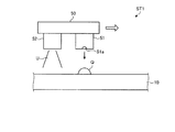
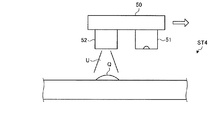
本実施形態に係るメディアの製造方法は、吐出工程ST1と、硬化工程ST2〜ST5とを順に行っている。本実施形態に係るメディアの製造方法では、紫外線硬化インクを吐出するインクジェットヘッド51と、紫外線硬化インクに紫外線を照射する紫外線照射ヘッド52とを搭載したキャリッジ50を有する印刷装置が用いられる。このような印刷装置としては、例えばミマキエンジニアリング製の「UJF−3042」または「UJF−6042」等が挙げられる。
In the media manufacturing method according to the present embodiment, the ejection step ST1 and the curing steps ST2 to ST5 are sequentially performed. In the media manufacturing method according to the present embodiment, a printing apparatus having a
まず、図6に示すように、吐出工程ST1では、再帰反射シート10を所定位置に配置した後、キャリッジ50を主走査方向に走査させる。そして、紫外線硬化インクをインクジェットヘッド51のノズル51aから吐出し、ノズル51aから吐出された紫外線硬化インクQを再帰反射シート10上に着弾させる。
First, as shown in FIG. 6, in the ejection step ST1, the
次に、硬化工程ST2〜ST5を行う。硬化工程ST2〜ST5では、再帰反射シート10上に着弾した紫外線硬化インクQに対して所定時間を空けて紫外線を複数回に分けて照射することで、紫外線硬化インクQを徐々に硬化させてレンズ層20を形成する。具体的には、再帰反射シート10上の紫外線硬化インクQを半硬化(仮硬化)させた後、レンズ層20の形状を形成後、紫外線硬化インクQを完全硬化(本硬化)させる。
Next, curing steps ST2 to ST5 are performed. In the curing steps ST <b> 2 to ST <b> 5, the ultraviolet curable ink Q that has landed on the
図7に示すように、第1照射工程ST2において、キャリッジ50を引き続き主走査方向に走査させることで、インクジェットヘッド51の移動方向に後行して紫外線照射ヘッド52を移動させ、紫外線照射ヘッド52から紫外線硬化インクQに紫外線Uを照射して半硬化させる。このように、紫外線硬化インクQの吐出後、紫外線Uを照射して半硬化させることができるため、紫外線硬化インクQの滲みを抑制し、レンズ層20を高精細に形成することができる。一方で、紫外線硬化インクQは、半硬化の状態であることから、再帰反射シート10に着弾した紫外線硬化インクQのエッジ部分(紫外線硬化インクQと着弾した再帰合反射シート10との境界部分)が広がってなだらかな形状となる。なお、第1照射工程ST2では、紫外線硬化インクQの着弾後、所定の時間(例えば、数sec)分だけ遅延させて、紫外線硬化インクQに紫外線を照射して半硬化させてもよい。
As shown in FIG. 7, in the first irradiation step ST <b> 2, the
次に、図8に示すように、キャリッジ復帰工程ST3においてキャリッジ50をもとの位置に復帰させ、再度キャリッジ50を主走査方向に移動させる。このとき、紫外線硬化インクQが半硬化の状態であるため、エッジ部分が広がり続ける。
Next, as shown in FIG. 8, the
次に、図9に示すように、第2照射工程ST4において、キャリッジ50を主走査方向に走査させることで、インクジェットヘッド51の移動方向に後行して紫外線照射ヘッド52を移動させ、紫外線照射ヘッド52から紫外線硬化インクQに紫外線Uを照射して完全硬化させる。
Next, as shown in FIG. 9, in the second irradiation step ST <b> 4, the
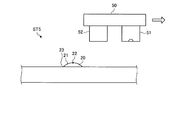
これにより、図10に示すように、再帰反射シート10にレンズ層20が形成される(完成工程ST5)。レンズ層20は、再帰反射シート10上に凸状に形成され、凸状の頂上部分22からエッジ部分23にかけてなだらかに湾曲した形状のレンズ面21を有するように形成される。第1照射工程ST2から第2照射工程ST4の間にキャリッジ復帰工程ST3を挟むため、紫外線硬化インクQが半硬化されてから完全硬化されるまでの間、紫外線硬化インクQのエッジ部分が広がる時間を確保することができる。
Thereby, as shown in FIG. 10, the
以上のように、本実施形態に係る製造方法によれば、紫外線硬化インクQを半硬化させることによって、紫外線硬化インクQの滲みを抑制することができる。また、紫外線硬化インクQを半硬化させた後、完全硬化させるまでの時間に、再帰反射シート10に着弾した紫外線硬化インクQのエッジ部分がなだらかな形状になる。このため、完全硬化後のレンズ層20は、凸状の頂上部分22からエッジ部分23にかけてなだらかに湾曲した形状のレンズ面21を有する形状となるため、レンズ効果を確実に発揮させることができる。
As described above, according to the manufacturing method according to the present embodiment, bleeding of the ultraviolet curable ink Q can be suppressed by semi-curing the ultraviolet curable ink Q. In addition, the edge portion of the ultraviolet curable ink Q that has landed on the
本発明の技術範囲は上記実施形態に限定されるものではなく、本発明の趣旨を逸脱しない範囲で適宜変更を加えることができる。例えば、上記実施形態では、レンズ層20の平面視における形状として、例えば円形、楕円形、多角形(三角形、四角形等)等である場合を例に挙げて説明したが、これに限定されない。
The technical scope of the present invention is not limited to the above-described embodiment, and appropriate modifications can be made without departing from the spirit of the present invention. For example, in the above embodiment, the case where the
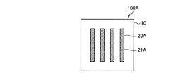
図11は、変形例に係るメディアの平面視における構成を示す図である。例えば、図11に示すメディア100Aのように、レンズ層20が平面視において縞状に形成されてもよい。メディア100Aでは、一方向に延びた帯状のレンズ層20Aが、再帰反射シート10上に、レンズ層20Aの幅方向(短手方向)に間隔を空けて並んで配置された構成となっている。この場合、レンズ層20Aのレンズ面21Aは、幅方向の両端にかけてなだらかな形状を有する構成とすることができる。
FIG. 11 is a diagram illustrating a configuration in a plan view of a medium according to a modification. For example, like the medium 100A shown in FIG. 11, the
図12は、変形例に係るメディアの平面視における構成を示す図である。例えば、図12に示すメディア100Bのように、レンズ層20Bが平面視において市松模様状に配置されてもよい。メディア100Bでは、例えば矩形状に形成されたレンズ層20Bが、再帰反射シート10上に、各角部同士が接するように配置された構成となっている。この場合、各レンズ層20Bのレンズ面21Bは、平面視で中央部分から4辺にかけてなだらかな形状を有する構成とすることができる。
FIG. 12 is a diagram illustrating a configuration of the medium according to the modification in a plan view. For example, like the medium 100B shown in FIG. 12, the
また、例えば、上記実施形態では、メディアの製造方法において、いわゆるグロス調印刷を行う場合を例に挙げて説明したが、これに限定されない。上記吐出工程ST1及び硬化工程ST2〜ST5においては、インクジェットヘッド51から吐出する紫外線硬化インクの吐出量、吐出タイミング、吐出期間等を制御し、紫外線照射ヘッド52から照射する紫外線の強度、半硬化及び完全硬化のタイミング、照射期間等を制御することにより、所望の形状、厚み、面積、寸法、パターンのレンズ層20を得ることができる。
Further, for example, in the above-described embodiment, the case where so-called glossy printing is performed in the media manufacturing method has been described as an example, but the present invention is not limited to this. In the discharge process ST1 and the curing processes ST2 to ST5, the discharge amount, discharge timing, discharge period, and the like of the ultraviolet curable ink discharged from the
例えば、吐出工程ST1において、紫外線硬化インクQを同一の着弾位置に複数回重ねて着弾させる重ね打ちを行ってレンズ層20を形成してもよい。この場合、例えばインクジェットヘッド51を1200dpi×1440dpiの解像度とし、8パスにて印刷を行うことができる。なお、パス数については特に限定されず、例えば、4パスであってもよい。重ね打ちを行う場合、1回ごとに吐出される紫外線硬化インクのインク量は、重ね打ちを行わない場合である通常時(つまり、1回だけ紫外線硬化インクを吐出する場合)に比して少ないものとなっている。また、重ね打ちでは、各回の紫外線硬化インクのインク量を同じ量とすることができるが、これに限定されず、少なくとも1回の吐出動作において異なるインク量で吐出してもよい。
For example, in the ejection step ST1, the
例えば、重ね打ちを行う場合、同じ着弾位置に2回、紫外線硬化インクQを吐出する場合を例に挙げて説明する。この場合、1回目の紫外線硬化インクQのインク量と、2回目の紫外線硬化インクQのインク量とを同じ量とすることができる。例えば、1回目及び2回目のインク量は、通常時(通常印刷時)に吐出されるインク量の50%程度とすることができる。このため、2回の重ね打ちを行うことで、インク量が100%となる。つまり、各回のインク量を50%に設定し、レンズ層20の形状データに基づく印刷条件で、2回繰り返して印刷することになる。
For example, in the case of performing overstrike, a case where the ultraviolet curable ink Q is discharged twice at the same landing position will be described as an example. In this case, the ink amount of the first ultraviolet curable ink Q and the ink amount of the second ultraviolet curable ink Q can be made the same amount. For example, the first and second ink amounts can be about 50% of the amount of ink ejected during normal operation (during normal printing). For this reason, the ink amount becomes 100% by performing the two-time overstrike. That is, the ink amount at each time is set to 50%, and printing is repeated twice under the printing condition based on the shape data of the
このように、重ね打ちを行うことにより、着弾した紫外線硬化インクQのドット径を、重ね打ちを行わない場合に比して大きくすることができる。また、1回ごとに吐出される紫外線硬化インクQのインク量を少なくすることで、レンズ層20を薄く形成することができる。
In this way, by performing overstrike, the dot diameter of the ultraviolet curable ink Q that has landed can be increased as compared with the case where the overstrike is not performed. Further, the
Q 紫外線硬化インク
U 紫外線
ST1 吐出工程
ST2〜ST5 硬化工程
10 再帰反射シート
11 基材
12 球状体
13 表面層
20,20A,20B レンズ層
21,21A,21B レンズ面
22 頂上部分
23 エッジ部分
30 着色層
40 透明層
50 キャリッジ
51 インクジェットヘッド
52 紫外線照射ヘッド
100,100A,100B,200,300 メディア
Q UV curable ink U UV ST1 Discharge process ST2 to
Claims (6)
前記再帰反射シート上に複数の前記球状体に跨るように形成された凸状のレンズ層と
を備えることを特徴とするメディア。 A retroreflective sheet having a plurality of spherical bodies that retroreflect incident light;
A convex lens layer formed on the retroreflective sheet so as to straddle the plurality of spherical bodies.
前記レンズ層は、前記着色層上に配置される
請求項1に記載のメディア。 A coloring layer disposed on the surface of the retroreflective sheet and coloring the retroreflective sheet;
The medium according to claim 1, wherein the lens layer is disposed on the colored layer.
請求項2に記載のメディア。 The medium according to claim 2, wherein the colored layer has light transparency.
請求項1から請求項3のいずれか一項に記載のメディア。 The medium according to any one of claims 1 to 3, wherein the lens layer has a lens surface that is gently curved from a convex top portion to an edge portion.
請求項1から請求項4のいずれか一項に記載のメディア。 The medium according to any one of claims 1 to 4, wherein the lens unit is arranged in a striped pattern or a checkered pattern in a plan view.
前記吐出した前記クリアインクに対して所定時間を空けて紫外線を複数回に分けて照射することで前記クリアインクを徐々に硬化させてレンズ層を形成する硬化工程と
を含むメディアの製造方法。 A discharge step of discharging a clear ink containing an ultraviolet curable ink onto a retroreflective sheet by an inkjet method;
A curing step of forming a lens layer by gradually curing the clear ink by irradiating the discharged clear ink with ultraviolet rays in a plurality of times with a predetermined time interval.
Priority Applications (1)
| Application Number | Priority Date | Filing Date | Title |
|---|---|---|---|
| JP2017105294A JP2018200410A (en) | 2017-05-29 | 2017-05-29 | Medium and method for manufacturing medium |
Applications Claiming Priority (1)
| Application Number | Priority Date | Filing Date | Title |
|---|---|---|---|
| JP2017105294A JP2018200410A (en) | 2017-05-29 | 2017-05-29 | Medium and method for manufacturing medium |
Publications (1)
| Publication Number | Publication Date |
|---|---|
| JP2018200410A true JP2018200410A (en) | 2018-12-20 |
Family
ID=64667161
Family Applications (1)
| Application Number | Title | Priority Date | Filing Date |
|---|---|---|---|
| JP2017105294A Pending JP2018200410A (en) | 2017-05-29 | 2017-05-29 | Medium and method for manufacturing medium |
Country Status (1)
| Country | Link |
|---|---|
| JP (1) | JP2018200410A (en) |
Cited By (2)
| Publication number | Priority date | Publication date | Assignee | Title |
|---|---|---|---|---|
| JP2020124877A (en) * | 2019-02-06 | 2020-08-20 | 株式会社沖データ | Inkjet printer |
| JP2021137975A (en) * | 2020-03-02 | 2021-09-16 | ミラクル工業株式会社 | Pseudo hologram printed matter |
Citations (8)
| Publication number | Priority date | Publication date | Assignee | Title |
|---|---|---|---|---|
| JPH11508653A (en) * | 1995-06-29 | 1999-07-27 | ミネソタ マイニング アンド マニュファクチャリング カンパニー | High-angle retroreflective products and manufacturing methods |
| JP2000321414A (en) * | 1999-04-28 | 2000-11-24 | Three M Innovative Properties Co | Photoretroreflective sheet |
| JP2002287134A (en) * | 2001-03-27 | 2002-10-03 | Seiko Epson Corp | Reflective liquid crystal device |
| WO2011122123A1 (en) * | 2010-03-31 | 2011-10-06 | 大日本スクリーン製造株式会社 | Inkjet printer and printed matter |
| JP2011215202A (en) * | 2010-03-31 | 2011-10-27 | Dainippon Screen Mfg Co Ltd | Inkjet printer and printed matter |
| JP2011215201A (en) * | 2010-03-31 | 2011-10-27 | Dainippon Screen Mfg Co Ltd | Ink jet printer and printed matter |
| JP2011224818A (en) * | 2010-04-16 | 2011-11-10 | Toppan Printing Co Ltd | Microlens ornamental body |
| WO2011142448A1 (en) * | 2010-05-14 | 2011-11-17 | 大日本スクリーン製造株式会社 | Printer and printing method |
-
2017
- 2017-05-29 JP JP2017105294A patent/JP2018200410A/en active Pending
Patent Citations (8)
| Publication number | Priority date | Publication date | Assignee | Title |
|---|---|---|---|---|
| JPH11508653A (en) * | 1995-06-29 | 1999-07-27 | ミネソタ マイニング アンド マニュファクチャリング カンパニー | High-angle retroreflective products and manufacturing methods |
| JP2000321414A (en) * | 1999-04-28 | 2000-11-24 | Three M Innovative Properties Co | Photoretroreflective sheet |
| JP2002287134A (en) * | 2001-03-27 | 2002-10-03 | Seiko Epson Corp | Reflective liquid crystal device |
| WO2011122123A1 (en) * | 2010-03-31 | 2011-10-06 | 大日本スクリーン製造株式会社 | Inkjet printer and printed matter |
| JP2011215202A (en) * | 2010-03-31 | 2011-10-27 | Dainippon Screen Mfg Co Ltd | Inkjet printer and printed matter |
| JP2011215201A (en) * | 2010-03-31 | 2011-10-27 | Dainippon Screen Mfg Co Ltd | Ink jet printer and printed matter |
| JP2011224818A (en) * | 2010-04-16 | 2011-11-10 | Toppan Printing Co Ltd | Microlens ornamental body |
| WO2011142448A1 (en) * | 2010-05-14 | 2011-11-17 | 大日本スクリーン製造株式会社 | Printer and printing method |
Cited By (2)
| Publication number | Priority date | Publication date | Assignee | Title |
|---|---|---|---|---|
| JP2020124877A (en) * | 2019-02-06 | 2020-08-20 | 株式会社沖データ | Inkjet printer |
| JP2021137975A (en) * | 2020-03-02 | 2021-09-16 | ミラクル工業株式会社 | Pseudo hologram printed matter |
Similar Documents
| Publication | Publication Date | Title |
|---|---|---|
| ES2583483T3 (en) | UV inkjet printing of vision control panels | |
| JP5112360B2 (en) | Inkjet printer and printing method | |
| EP2396682B1 (en) | Device for directing light beams, illustration device, method for producing a device and an illustration device | |
| US20170136706A1 (en) | Three-dimensional object fabrication device, three-dimensional object fabrication method, and three-dimensional object | |
| US20200316849A1 (en) | Building apparatus, building method, and object | |
| US10926455B2 (en) | Apparatus for forming three-dimensional object and method for forming three-dimensional object | |
| JPH07311556A (en) | Display with enhanced highlight | |
| WO2015163259A1 (en) | Printing method and printing device | |
| JP6719961B2 (en) | Modeling apparatus and modeling method | |
| JP6454497B2 (en) | Three-dimensional object forming apparatus and three-dimensional object forming method | |
| JP2018200410A (en) | Medium and method for manufacturing medium | |
| JP6861053B2 (en) | Modeling equipment and modeling method | |
| JP5526569B2 (en) | Stereoscopic image forming apparatus and stereoscopic image forming method | |
| JP6815791B2 (en) | Modeling equipment and modeling method | |
| JP5656279B2 (en) | Inkjet printer and method for producing printed matter | |
| JP2018149778A (en) | Molding apparatus and molding method | |
| CN104101938A (en) | Backlight Light Guide Plate, Method For Manufacturing Backlight Light Guide Plate And Ink-jet Printer | |
| JP2022505917A (en) | 3D object inkjet printing method, printing equipment and computer-readable storage medium | |
| US10220644B2 (en) | Printing device and printing method | |
| JP2019107816A (en) | Manufacturing method of molded article, molding system, and molding apparatus | |
| JP2016107637A (en) | Apparatus for molding three-dimensional object and method for molding three-dimensional object | |
| JP2020147046A (en) | Shaping device | |
| JP6615008B2 (en) | Decorative body | |
| WO2011122123A1 (en) | Inkjet printer and printed matter | |
| EP3527403B1 (en) | Multilayered printed matter |
Legal Events
| Date | Code | Title | Description |
|---|---|---|---|
| A621 | Written request for application examination |
Free format text: JAPANESE INTERMEDIATE CODE: A621 Effective date: 20191224 |
|
| A977 | Report on retrieval |
Free format text: JAPANESE INTERMEDIATE CODE: A971007 Effective date: 20201021 |
|
| A131 | Notification of reasons for refusal |
Free format text: JAPANESE INTERMEDIATE CODE: A131 Effective date: 20201110 |
|
| A601 | Written request for extension of time |
Free format text: JAPANESE INTERMEDIATE CODE: A601 Effective date: 20201228 |
|
| A521 | Request for written amendment filed |
Free format text: JAPANESE INTERMEDIATE CODE: A523 Effective date: 20210309 |
|
| A02 | Decision of refusal |
Free format text: JAPANESE INTERMEDIATE CODE: A02 Effective date: 20210907 |
|
| A521 | Request for written amendment filed |
Free format text: JAPANESE INTERMEDIATE CODE: A523 Effective date: 20211207 |
|
| C60 | Trial request (containing other claim documents, opposition documents) |
Free format text: JAPANESE INTERMEDIATE CODE: C60 Effective date: 20211207 |
|
| A911 | Transfer to examiner for re-examination before appeal (zenchi) |
Free format text: JAPANESE INTERMEDIATE CODE: A911 Effective date: 20211214 |
|
| C21 | Notice of transfer of a case for reconsideration by examiners before appeal proceedings |
Free format text: JAPANESE INTERMEDIATE CODE: C21 Effective date: 20211221 |
|
| A912 | Re-examination (zenchi) completed and case transferred to appeal board |
Free format text: JAPANESE INTERMEDIATE CODE: A912 Effective date: 20220304 |
|
| C211 | Notice of termination of reconsideration by examiners before appeal proceedings |
Free format text: JAPANESE INTERMEDIATE CODE: C211 Effective date: 20220308 |
|
| C22 | Notice of designation (change) of administrative judge |
Free format text: JAPANESE INTERMEDIATE CODE: C22 Effective date: 20220830 |
|
| C13 | Notice of reasons for refusal |
Free format text: JAPANESE INTERMEDIATE CODE: C13 Effective date: 20221011 |
|
| C23 | Notice of termination of proceedings |
Free format text: JAPANESE INTERMEDIATE CODE: C23 Effective date: 20230117 |
|
| C03 | Trial/appeal decision taken |
Free format text: JAPANESE INTERMEDIATE CODE: C03 Effective date: 20230214 |
|
| C30A | Notification sent |
Free format text: JAPANESE INTERMEDIATE CODE: C3012 Effective date: 20230214 |