JP2018196622A - Electronic apparatus, method, and program - Google Patents
Electronic apparatus, method, and program Download PDFInfo
- Publication number
- JP2018196622A JP2018196622A JP2017102938A JP2017102938A JP2018196622A JP 2018196622 A JP2018196622 A JP 2018196622A JP 2017102938 A JP2017102938 A JP 2017102938A JP 2017102938 A JP2017102938 A JP 2017102938A JP 2018196622 A JP2018196622 A JP 2018196622A
- Authority
- JP
- Japan
- Prior art keywords
- obstacle
- map
- electronic device
- cleaning
- information
- Prior art date
- Legal status (The legal status is an assumption and is not a legal conclusion. Google has not performed a legal analysis and makes no representation as to the accuracy of the status listed.)
- Pending
Links
- 238000000034 method Methods 0.000 title claims description 15
- 238000004140 cleaning Methods 0.000 claims description 84
- 230000007246 mechanism Effects 0.000 claims description 10
- 230000032258 transport Effects 0.000 claims description 10
- 230000008859 change Effects 0.000 claims description 8
- 230000002411 adverse Effects 0.000 claims description 4
- 230000000694 effects Effects 0.000 claims description 4
- 230000007723 transport mechanism Effects 0.000 claims 2
- 230000002093 peripheral effect Effects 0.000 abstract 2
- 238000005259 measurement Methods 0.000 abstract 1
- 238000011156 evaluation Methods 0.000 description 50
- 238000001514 detection method Methods 0.000 description 49
- 230000006872 improvement Effects 0.000 description 42
- 238000010586 diagram Methods 0.000 description 13
- 239000000428 dust Substances 0.000 description 12
- 238000012545 processing Methods 0.000 description 8
- 238000004891 communication Methods 0.000 description 7
- 230000009467 reduction Effects 0.000 description 6
- 230000007423 decrease Effects 0.000 description 5
- 230000008569 process Effects 0.000 description 4
- 230000004913 activation Effects 0.000 description 2
- 239000003086 colorant Substances 0.000 description 2
- 238000012552 review Methods 0.000 description 2
- 241001270131 Agaricus moelleri Species 0.000 description 1
- 125000002066 L-histidyl group Chemical group [H]N1C([H])=NC(C([H])([H])[C@](C(=O)[*])([H])N([H])[H])=C1[H] 0.000 description 1
- 230000001133 acceleration Effects 0.000 description 1
- 230000008901 benefit Effects 0.000 description 1
- 210000000038 chest Anatomy 0.000 description 1
- 230000007613 environmental effect Effects 0.000 description 1
- 230000006870 function Effects 0.000 description 1
- 238000012986 modification Methods 0.000 description 1
- 230000004048 modification Effects 0.000 description 1
- 231100000989 no adverse effect Toxicity 0.000 description 1
Images


Abstract
Description
本実施形態は、電子機器、方法及びプログラムに関する。 The present embodiment relates to an electronic device, a method, and a program.
近年、床面の清掃や荷物の運搬のために、所定の領域を自律的に走行可能なロボットの普及が進んできている。ロボットを自律走行させるためには、自律走行させたい所定領域の環境地図をロボットに予めインプットしておく必要がある。これにより、環境地図に基づいた走行経路の作成が可能となり、当該走行経路に沿った自律走行が実現される。 In recent years, robots capable of autonomously traveling in a predetermined area are being promoted for cleaning the floor and transporting luggage. In order for the robot to autonomously travel, it is necessary to input an environment map of a predetermined area to be autonomously traveled to the robot in advance. As a result, a travel route based on the environment map can be created, and autonomous travel along the travel route is realized.
しかしながら、自律走行させたい所定領域の環境が、常に同じであるとは限らないので、環境地図がインプットされたときと所定領域の環境が異なる場合、ロボットは、所定領域を精度良く自律走行することができない可能性がある。これによれば、ロボットの清掃性能や運搬性能の上昇が見込めないだけでなく、これら性能の低下を招く恐れがある。 However, since the environment of the predetermined area to be autonomously traveled is not always the same, if the environment of the predetermined area is different from that when the environment map is input, the robot must autonomously travel the predetermined area with high accuracy. May not be possible. According to this, not only the robot cleaning performance and transport performance cannot be expected, but also the performance may be reduced.
このような恐れをなくすためには、ロボットのユーザが、所定領域の環境を、現状の環境を踏まえつつも、環境地図がインプットされたときの環境に近づくように整えれば良い。しかしながら、所定領域の環境をどのように整えたときに、ロボットがどの程度の性能を発揮するかをユーザが知る手段が必要である。 In order to eliminate such a fear, the user of the robot may arrange the environment of the predetermined area so as to be close to the environment when the environment map is input while taking the current environment into consideration. However, there is a need for a means for the user to know how much the robot will perform when the environment of the predetermined area is adjusted.
本発明の一実施形態が解決しようとする課題は、ロボットが自律走行する所定領域の環境をどのように整えれば、ロボットがどの程度の性能を発揮するかをユーザに提示可能な電子機器、方法及びプログラムを提供することである。 The problem to be solved by an embodiment of the present invention is an electronic device capable of presenting to a user how much the robot will exhibit if the environment of a predetermined area where the robot autonomously travels is arranged, It is to provide a method and program.
一実施形態に係る電子機器は、電子機器の位置を変更可能な駆動手段と、第1時刻の地図の情報を記憶する記憶手段と、前記第1時刻よりも後の第2時刻の周囲の物体の位置を測定する測定手段と、前記地図と前記周囲の物体の位置との相違部分を障害物と特定する特定手段と、前記障害物により影響を受ける性能の指標の大きさを算出する算出手段と、前記地図上に、前記障害物の位置と、前記障害物により影響を受ける性能の指標の大きさとを識別可能に表示するための情報を出力する出力手段とを備える。 An electronic device according to an embodiment includes a driving unit that can change the position of the electronic device, a storage unit that stores map information at a first time, and an object around a second time after the first time. Measuring means for measuring the position of the object, specifying means for specifying the difference between the map and the position of the surrounding object as an obstacle, and calculating means for calculating the size of the performance indicator affected by the obstacle And an output means for outputting information for displaying the position of the obstacle and the size of the performance index affected by the obstacle in an identifiable manner on the map.
以下、図面を参照して実施形態を説明する。
図1は、一実施形態に係る電子機器の概略構成例を示す図である。なお、本実施形態では、電子機器が、自律走行しながら建物内の床面を清掃するロボット掃除機である場合を想定して説明するが、これに限定されず、電子機器は、空港や駅の床面、道路等を掃除する掃除機や、工場内において荷物を運搬するロボット(移動体)等であっても良い。
Hereinafter, embodiments will be described with reference to the drawings.
FIG. 1 is a diagram illustrating a schematic configuration example of an electronic apparatus according to an embodiment. In the present embodiment, the electronic device is described assuming a case where the electronic device is a robot cleaner that cleans the floor surface in the building while traveling autonomously. However, the electronic device is not limited to this, and the electronic device may be an airport or a station. It may be a vacuum cleaner that cleans floors, roads, etc., or a robot (moving body) that carries luggage in a factory.
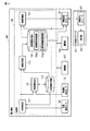
図1に示す電子機器100は、位置検出センサ101、障害物検出センサ102、集塵部103、駆動部104、制御部105及び表示部106等を備えている。
An
位置検出センサ101は、電子機器100の現在位置を特定するために用いられる情報を収集可能なセンサ装置である。具体的には、位置検出センサ101は、超音波センサであり、電子機器100の周囲に超音波を発信し、反射される超音波を受信することで、電子機器100の周囲に位置する物体(例えば、障害物や壁等)までの距離を測定する。位置検出センサ101によって収集された周囲の物体までの距離を示す距離情報は、後述する制御部105に出力される。
The
なお、本実施形態では、位置検出センサ101が超音波センサである場合を想定して説明するが、これに限定されず、例えばGPS(Global Positioning System)やジャイロセンサ、加速度センサ等、電子機器100の現在位置を特定可能なセンサ装置であれば、任意のセンサ装置が位置検出センサ101として使用されても良い。
In this embodiment, the
障害物検出センサ102は、後述する制御部105によって作成される走行経路に沿って走行する電子機器100の進行方向に障害物が有るか否かを特定可能なセンサ装置(換言すると、電子機器100の周囲の物体の位置を測定可能なセンサ装置)である。具体的には、障害物検出センサ102は、位置検出センサ101と同様に超音波センサであり、電子機器100の進行方向に向かって超音波を発信し、反射される超音波を受信することで、電子機器100の進行方向に位置する物体までの距離を測定し、当該進行方向に障害物が有るか否かを特定する。障害物検出センサ102によって特定された障害物の有無を示す情報と、障害物が有る場合には、その障害物までの距離を示す情報とを含む障害物情報は、後述する制御部105に出力される。
The
なお、本実施形態では、障害物検出センサ102が超音波センサである場合を想定して説明するが、これに限定されず、電子機器100の進行方向に位置する障害物の有無を特定可能なセンサ装置であれば、任意のセンサ装置が障害物検出センサ102として使用されても良い。
In the present embodiment, the description will be made assuming that the
集塵部103は、床面のゴミ等を吸い込んで集める機能を有する。集塵部103は、例えば、吸込モーターと、吸込モーターによって床面のゴミ等を含んだ空気を吸い込む吸込部と、吸込部によって吸い込まれたゴミ等を溜めておく集塵室とによって構成される。なお、集塵部103の構成は、上記した構成に限定されず、公知の構成であれば、どのような構成であっても構わない。
The
駆動部104は、電子機器100を自律走行させるための駆動機構を有する。駆動部104は、例えば、複数の車輪と、車輪を回転させるための駆動モーターとによって構成される。なお、駆動部104の構成は、上記した構成に限定されず、公知の構成であれば、どのような構成であっても構わない。
The
制御部105は、電子機器100を構成する各部の動作を制御する。具体的には、制御部105は、図1に示すように、地図情報記憶部110、位置検出部111、障害物検出部112、経路作成部113、経路情報記憶部114及び経路評価部115等を備えている。なお、制御部105に含まれる各部111〜113,115は、図示せぬメモリに記憶されたプログラムが図示しないCPU(Control Processing Unit)によって実行されることで実現される。
The
地図情報記憶部110は、電子機器100によって清掃される清掃領域の環境地図を記憶している。具体的には、地図情報記憶部110は、障害物が配置されていない状態の清掃領域を示す第1地図の情報と、障害物が配置された状態の清掃領域を示す第2地図の情報とを記憶している。
The map
第1地図は、例えば、新たな清掃領域を電子機器100の清掃領域として追加する際に、当該新たな清掃領域に障害物となる物体が何も配置されていない状態で、当該新たな清掃領域の広さや形状を測定するためのスキャンが実行された結果として作成される地図である。第2地図は、実際に清掃領域を清掃した際に、電子機器100の走行経路を作成(更新)するためのスキャンが実行された結果として作成される地図である。
For example, when a new cleaning area is added as a cleaning area of the
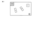
図2は第1地図の一例を示す図であり、図3は第2地図の一例を示す図である。図2に示す第1地図によれば、清掃領域となる部屋が真四角の部屋ではなく、一部の壁が出っ張っていることが分かる。また、図3に示す第2地図によれば、清掃領域となる部屋には、電子機器100を充電するためのベースステーションBSの他に、第1地図との相違部分である3つの障害物A〜Cが配置されていることが分かる。なお、第1地図及び第2地図は、図2及び図3に示すように、壁等、動かすことのできない物体(斜線ありで表示される領域)と、障害物A〜CやベースステーションBS等、動かすことのできる物体(斜線なしで表示される領域)とを識別可能な地図である方が好ましい。
FIG. 2 is a diagram illustrating an example of the first map, and FIG. 3 is a diagram illustrating an example of the second map. According to the 1st map shown in FIG. 2, it turns out that the room used as a cleaning area is not a square room, and some walls protrude. Moreover, according to the 2nd map shown in FIG. 3, in the room used as a cleaning area, in addition to the base station BS for charging the
なお、本実施形態では、地図情報記憶部110には、第1地図及び第2地図といった2種類の地図が記憶されている場合を想定しているが、これに限定されず、地図情報記憶部110には、第3地図がさらに記憶されていて、第1地図及び第2地図と同様に利用されても良い。第3地図は、タンスや机等、移動させる頻度の少ない物体(固定物)だけが清掃領域に配置された状態でスキャンが実行された結果として作成される地図である。この第3地図は、上記した状態でのスキャンの他に、第2地図が作成・更新される過程で、常に同じ場所に位置する物体を障害物ではなく、固定物とみなすことで、第2地図の後に作成されても良い。また、この第3地図は、後述する障害物検出部112により、固定物の位置に所定量以上の変化が検出された場合に、模様替えがあったとして、更新されても良い。
In the present embodiment, it is assumed that the map
また、本実施形態では、上記したように地図情報記憶部110には、第1地図及び第2地図といった2種類の地図が記憶されている場合を想定しているが、これに限定されず、地図情報記憶部110には、第2地図だけが記憶されているとしても良い。
In the present embodiment, as described above, it is assumed that the map
位置検出部111は、位置検出センサ101から出力された距離情報と、地図情報記憶部110に記憶された第2地図とに基づいて、電子機器100の現在位置を特定(検出)する。具体的には、位置検出部111は、位置検出センサ101からの距離情報によって示される清掃領域内に配置された障害物までの距離と、第2地図によって示される清掃領域に配置された障害物の配置とを照会し、電子機器100の現在位置を特定する。電子機器100の現在位置を示す現在位置情報は、障害物検出部112及び経路作成部113に出力される。
The
障害物検出部112は、障害物検出センサ102から出力された障害物情報と、地図情報記憶部110に記憶された第2地図と、位置検出部111から出力された現在位置情報とに基づいて、電子機器100の現在の進行方向に対する障害物の有無が、第2地図上の障害物の配置と一致しているか否か(相違ないか否か)を判定する。
The
なお、障害物情報によって障害物が有ると示されているにも関わらず、第2地図によれば電子機器100の進行方向には障害物が無い場合、または、障害物情報によって障害物が無いと示されているにも関わらず、第2地図によれば電子機器100の進行方向には障害物が有る場合、障害物検出部112は、第2地図が作成された時点(または前回の更新時)から障害物の配置が変更されていると判定し、第2地図を更新する処理を実行する。更新後の第2地図は、更新前の第2地図に代えて、地図情報記憶部110に記憶される。
Although there is no obstacle in the traveling direction of the
また、障害物検出部112は、第2地図が作成された時点から障害物の配置が変更されていると判定した場合、今回の清掃における電子機器100の走行経路を見直すよう経路作成部113に指示する。
In addition, when the
経路作成部113は、地図情報記憶部110に記憶された第2地図と、位置検出部111から出力された現在位置情報とに基づいて、現在位置情報によって示される位置にいる電子機器100の走行経路を作成する。具体的には、経路作成部113は、現在位置情報によって示される電子機器100の現在位置が当該電子機器100を充電するためのベースステーションBSが設置された場所である場合、第2地図によって示される障害物を避けながら(迂回しながら)清掃するための走行経路(初期経路)を作成する。
The
また、経路作成部113は、現在位置情報によって示される電子機器100の現在位置が、電子機器100を充電するためのベースステーションBSが設置された場所でない上に、障害物検出部112から経路を見直すよう指示を受けた場合、更新後の第2地図によって示される新たな障害物を避けるように走行経路を修正する、または、更新後の第2地図によって示される障害物が有ったとされる場所を避けずに直進するように走行経路を修正する。
In addition, the
経路情報記憶部114は、図1に示すように、実経路情報記憶部114aと仮想経路情報記憶部114bとを含む。実経路情報記憶部114aは、電子機器100が今回の清掃時に、実際に走行した経路である実経路を示す実経路情報を記憶している。一方で、仮想経路情報記憶部114bは、電子機器100が今回の清掃時に使用した第2地図上に位置する障害物を除去したと仮定した上で、電子機器100が走行可能な経路である仮想経路を示す仮想経路情報を記憶している。
As shown in FIG. 1, the route
なお、仮想経路情報は、電子機器100が今回の清掃時に使用した第2地図上に位置する障害物の数に応じて作成され、記憶される。例えば、今回の清掃時に使用した第2地図が図3に示す第2地図であった場合、仮想経路情報記憶部114bには、障害物A〜Cのそれぞれを除去したと仮定した場合の仮想経路情報と、障害物A,B、障害物B,C、障害物C,Aを除去したと仮定した場合の仮想経路情報と、障害物A〜Cの全てを除去したと仮定した場合の仮想経路情報とが記憶される。
The virtual route information is created and stored according to the number of obstacles located on the second map used by the
経路評価部115は、実経路情報記憶部114aに記憶された実経路情報によって示される走行経路(実経路)に対する評価指標を算出する。同様に、経路評価部115は、仮想経路情報記憶部114bに記憶された仮想経路情報によって示される走行経路(仮想経路)に対する評価指標を算出する。
The
なお、ここでの評価指標とは清掃性能(掃除性能)を示し、例えば、清掃領域に配置された障害物に起因して生じてしまう未清掃領域(換言すると、障害物があることにより清掃することができない領域)の面積(具体的には、X[m2]等)がこれに相当する。この場合、未清掃領域の面積が小さい程、清掃性能は高く、未清掃領域の面積が大きい程、清掃性能が低いことが分かる。 The evaluation index here indicates cleaning performance (cleaning performance). For example, an uncleaned area (in other words, cleaning is performed due to an obstacle) caused by an obstacle placed in the cleaning area. Area (specifically, X [m 2 ] etc.) corresponds to this. In this case, it can be seen that the smaller the area of the uncleaned region, the higher the cleaning performance, and the larger the area of the uncleaned region, the lower the cleaning performance.
但し、評価指標は、未清掃領域の面積に限定されず、例えば、清掃可能領域の面積であっても良いし、清掃領域の面積に対する未清掃領域の面積の割合や、清掃領域の面積に対する清掃可能領域の面積の割合等であっても構わない。さらには、評価指標は、清掃領域を清掃する際の走行距離や、清掃領域を清掃し終えるまでにかかる時間等であっても良い。 However, the evaluation index is not limited to the area of the uncleaned area, and may be, for example, the area of the cleanable area, the ratio of the area of the uncleaned area to the area of the cleaned area, or the cleaning with respect to the area of the cleaned area It may be the ratio of the area of the possible region. Furthermore, the evaluation index may be a travel distance when cleaning the cleaning area, a time taken to finish cleaning the cleaning area, or the like.
なお、本実施形態では、電子機器100がロボット掃除機である場合を想定しているため、評価指標は清掃性能を示すものとしたが、電子機器100が工場内において荷物を運搬するロボットである場合、評価指標は運搬清掃を示すものとなる。具体的には、第1地点から第2地点に移動する際の走行距離や、第1地点から第2地点に移動し終えるまでにかかる時間等が、これに相当する。
In the present embodiment, since it is assumed that the
経路評価部115は、実経路情報によって示される実経路に対応した評価指標と、仮想経路情報によって示される仮想経路に対応した評価指標とを比較し、電子機器100が仮想経路を走行した場合、今回の清掃時に走行した実経路を走行する場合に比べて、どれだけ清掃性能が向上するかを示す評価指標の改善率(換言すると、掃除の改善率)を算出する。
The
例えば、上記した評価指標が未清掃領域の面積である場合、経路評価部115は、実経路情報によって示される実経路に対応した未清掃領域の面積と、仮想経路情報によって示される仮想経路に対応した未清掃領域の面積との差分を算出する。これによれば、未清掃領域がどれだけ減少するのかを評価指標の改善率として算出することができる。
For example, when the evaluation index is the area of the uncleaned area, the
また、上記した評価指標が清掃可能領域の面積である場合、経路評価部115は、実経路情報によって示される実経路に対応した清掃可能領域の面積と、仮想経路情報によって示される仮想経路に対応した清掃可能領域との差分を算出する。これによれば、清掃可能領域がどれだけ増加するのかを評価指標の改善率として算出することができる。
When the evaluation index is the area of the cleanable area, the
なお、今回の清掃時に実際に走行した実経路だけでなく、過去の清掃時に走行した実経路に対応した評価指標も参照することで、過去から現在にかけて未清掃の領域(または、過去から現在にかけて清掃回数が少ない領域、つまり、塵埃が堆積している領域)を抽出し、当該抽出された領域をどれだけ清掃できるかが、評価指標の改善率として算出されても良い。 In addition, by referring not only to the actual route actually traveled at the time of this cleaning, but also to the evaluation index corresponding to the actual route traveled at the time of past cleaning, an uncleaned area from the past to the present (or from the past to the present) An area where the number of times of cleaning is small, that is, an area where dust is accumulated may be extracted, and how much the extracted area can be cleaned may be calculated as the improvement rate of the evaluation index.
経路評価部115によって算出された評価指標の改善率を示す性能向上情報は、表示部106に出力される。
The performance improvement information indicating the improvement rate of the evaluation index calculated by the
なお、経路評価部115は、実経路及び仮想経路に対する複数種類の評価指標を算出し、全ての種類について、評価指標の改善率を算出しても良い。例えば、未清掃領域の面積と、清掃領域を清掃する際の走行距離といった2種類の評価指標が算出され、未清掃領域がどれだけ減少するのかを示す評価指標の改善率と、走行距離がどれだけ短縮するのかを示す評価指標の改善率とが、それぞれ算出されても良い。この場合、表示部106には、未清掃領域の減少値に関する性能向上情報と、走行距離の短縮値に関する性能向上情報とが出力される。
Note that the
表示部106は、いわゆるディスプレイであり、制御部105内の経路評価部115から出力された性能向上情報や地図情報記憶部110に記憶された地図情報が表示される。
The
図4は、表示部106に表示される表示画面の一例を示す図である。なお、ここでは、性能向上情報が、未清掃領域の減少割合に関する情報である場合を想定している。
図4では、経路評価部115から出力された性能向上情報と、地図情報記憶部110に記憶された第2地図とが利用された場合の表示画面を例示している。図4に示す表示画面によれば、ユーザは、性能向上情報PAから、第2地図上のオブジェクトOAにより示される障害物Aを除去すれば、未清掃領域がXA%減少することを把握することができる。同様に、図4に示す表示画面によれば、ユーザは、性能向上情報PBから、第2地図上のオブジェクトOBにより示される障害物Bを除去すれば、未清掃領域がXB%減少することを把握することができる。さらに、図4に示す表示画面によれば、ユーザは、性能向上情報PCから、第2地図上のオブジェクトOCにより示される障害物Cを除去すれば、未清掃領域がXC%減少することを把握することができる。
FIG. 4 is a diagram illustrating an example of a display screen displayed on the
FIG. 4 illustrates a display screen when the performance improvement information output from the
なお、ここでは、障害物A〜Cのそれぞれを除去した場合の性能向上情報だけが表示される場合を例示したが、障害物A,B、障害物B,C、障害物C,Aを除去した場合の性能向上情報と、障害物A〜Cの全てを除去した場合の性能向上情報とがさらに表示されても良い。 In addition, although the case where only the performance improvement information when each of the obstacles A to C is displayed is illustrated here, the obstacles A and B, the obstacles B and C, and the obstacles C and A are removed. The performance improvement information when the obstacles A to C are removed and the performance improvement information when all the obstacles A to C are removed may be further displayed.
第2地図上の各障害物A〜Cを示す各オブジェクトOA〜OCは、図4に示すように、所定の色でそれぞれ色付けされて表示されても良い。例えば、未清掃領域の減少割合がXA>XB>XCの関係を有している場合、除去することで未清掃領域を最も減らすことのできる障害物AのオブジェクトOAを第1色で表示し、除去することで未清掃領域をある程度減らすことのできる障害物BのオブジェクトOBを第2色で表示し、除去したとしても未清掃領域をあまり減らすことのできない障害物CのオブジェクトOCを第3色で表示するとしても良い。 Each object O A ~ O C showing a second each obstacle A~C on the map, as shown in FIG. 4, it may be displayed are colored respectively in a predetermined color. For example, when the reduction ratio of the uncleaned area has a relationship of X A > X B > X C , the object O A of the obstacle A that can most reduce the uncleaned area by removing it is the first color. displayed in the object O B of the obstacle B that can reduce the uncleaned area somewhat by removing displayed in a second color, nor can be reduced uncleaned area so as to remove the obstacle C object the O C may be displayed in a third color.
これによれば、ユーザは、どの障害物を除去すれば、未清掃領域が減りやすいか、つまり、清掃領域がよりきれいになるかを色(直感的に)で判別することができるようになる。 According to this, the user can determine by color (intuitively) which obstacles should be removed to easily reduce the uncleaned area, that is, to clean the cleaned area.
なお、第1〜第3色は、第1色が最も濃く、以降は段階的に薄くなるグレースケールであっても良いし、赤色、黄色及び青色等であっても良い。より詳しくは、清掃性能の上昇が最も見込める障害物のオブジェクトを第1色である赤色又は最も濃い色で表示し、2番目に清掃性能の上昇が見込める障害物のオブジェクトを第2色である黄色又は2番目に濃い色で表示し、清掃性能の上昇が最も見込めない障害物のオブジェクトを第3色である青色又は最も薄い色で表示するとしても良い。 Note that the first to third colors may be gray scales in which the first color is the darkest and then gradually lighter, or may be red, yellow, blue, or the like. More specifically, an obstacle object that is most likely to have an increase in cleaning performance is displayed in red or the darkest color that is the first color, and an obstruction object that is expected to have an increase in cleaning performance is the second color that is yellow. Alternatively, it may be displayed in the second darkest color, and an obstacle object that is most unlikely to be improved in cleaning performance may be displayed in the third color blue or the lightest color.
図4では、清掃領域内に3つの障害物A〜Cが配置されていた場合を想定しているため、障害物のオブジェクトの色もまた3種類となるが、これに限定されず、障害物のオブジェクトの色の種類は、清掃領域内に配置される障害物の数に応じて決定される。 In FIG. 4, since it is assumed that three obstacles A to C are arranged in the cleaning area, there are also three types of obstacle object colors. The color type of the object is determined according to the number of obstacles arranged in the cleaning area.
また、図4では、性能向上情報が表形式で表示部106に表示される場合を例示したが、性能向上情報の表示形式はこれに限定されず、例えば図5に示すように、第2地図上の各障害物A〜CのオブジェクトOA〜OC近辺に、それぞれに対応する性能向上情報が表示されても良い。これによれば、図4に示す場合に比べて、より大きな第2地図を表示することができるという利点を得ることができる。
FIG. 4 illustrates the case where the performance improvement information is displayed on the
さらに、図4では、未清掃領域の減少割合に関する性能向上情報だけが表示される場合を例示しているが、これに限定されず、経路評価部115から複数種類の性能向上情報が出力されている場合、複数種類の性能向上情報が表示されるとしても良い。例えば、未清掃領域の減少割合に関する性能向上情報に加えて、走行距離の短縮値に関する性能向上情報が経路評価部115から出力されている場合、未清掃領域の減少割合に加えて、走行距離の短縮値がさらに表示されても良い。
Furthermore, FIG. 4 illustrates a case where only the performance improvement information related to the reduction ratio of the uncleaned area is displayed, but the present invention is not limited to this, and multiple types of performance improvement information are output from the
次に、図6を参照して、図4とは異なる表示画面の一例について説明する。
図6では、経路評価部115から出力された性能向上情報と、地図情報記憶部110に記憶された第2地図とに加えて、経路情報記憶部114に記憶された経路情報がさらに利用された場合の表示画面を例示している。なお、ここでは、第2地図上の各障害物A〜CのオブジェクトOA〜OCをユーザはタップする等して選択・指定可能であるものとし、障害物AのオブジェクトOAが選択・指定された場合を想定している。
Next, an example of a display screen different from that in FIG. 4 will be described with reference to FIG.
In FIG. 6, in addition to the performance improvement information output from the
図6に示す表示画面によれば、ユーザは、性能向上情報PAから、第2地図上のオブジェクトOAにより示される障害物Aを除去すれば、未清掃領域がXA%減少することを把握することができると共に、障害物Aを除去した場合の電子機器100の走行経路が仮想経路RAとなることを把握することができる。また、ユーザは、今回の清掃時の実経路rと、上記した仮想経路RAとの違いも把握することができる。
According to the display screen shown in FIG. 6, the user, from the performance improvement information P A, by removing an obstacle A shown by the object O A on the second map, that uncleaned area decreases X A% It is possible to grasp the fact that the travel route of the
なお、上記したように、ここでは、障害物AのオブジェクトOAが選択・指定された場合を想定して説明したが、障害物B,CのオブジェクトOB,OCがユーザにより選択・指定された場合も同様に、表示画面には、選択・指定されたオブジェクトにより示される障害物が除去された場合の未清掃領域の減少割合と、今回の清掃時の実経路と、選択・指定されたオブジェクトにより示される障害物が除去された場合の仮想経路とが表示される。 As described above, the case where the object OA of the obstacle A is selected / designated is described here, but the objects OB, OC of the obstacles B , C are selected / designated by the user. Similarly, on the display screen, the reduction rate of the uncleaned area when the obstacle indicated by the selected / designated object is removed, and the actual path at the time of this cleaning are selected / designated. The virtual path when the obstacle indicated by the object is removed is displayed.
また、図6では、今回の清掃時の実経路rと、ユーザによって選択・指定されたオブジェクトOAにより示される障害物を除去した場合の仮想経路RAとが1つの地図上に共に表示される場合を例示したが、表示方法はこれに限定されず、例えば、2つの地図が表示され、一方の地図に実経路rが表示され、他方の地図に仮想経路RAが表示されるとしても良い。あるいは、1つの地図上において、実経路rと仮想経路RAとが交互に切替表示されるとしても良い。 Further, in FIG. 6, the actual path r during this cleaning, the virtual route R A in the case of removal of the obstacle indicated by the object O A selected-specified by the user is displayed together on a single map However, the display method is not limited to this. For example, two maps are displayed, the actual route r is displayed on one map, and the virtual route RA is displayed on the other map. good. Alternatively, the real route r and the virtual route RA may be alternately displayed on one map.
さらに、図7を参照して、図4,6とは異なる表示画面の一例について説明する。
図7では、図6に示した表示画面と同様に、経路評価部115から出力された性能向上情報と、地図情報記憶部110に記憶された第2地図とに加えて、経路情報記憶部114に記憶された経路情報がさらに利用された場合の表示画面を例示している。なお、ここでは、図6の場合と同様に、第2地図上の各障害物A〜CのオブジェクトOA〜OCをユーザはタップする等して選択・指定可能であるものとし、障害物AのオブジェクトOAが選択・指定された場合を想定している。
Furthermore, an example of a display screen different from that in FIGS. 4 and 6 will be described with reference to FIG.
7, in addition to the performance improvement information output from the
図7に示す表示画面によれば、ユーザは、性能向上情報PAから、第2地図上のオブジェクトOAにより示される障害物Aを除去すれば、未清掃領域がXA%減少することを把握することができると共に、障害物Aを除去した場合の電子機器100の走行経路では未清掃領域となるであろう清掃不可領域Y1,Y2を把握することができる。つまり、ユーザは、障害物Aを除去した際に、清掃不可領域Y1,Y2を自身の手で清掃すれば良いことを把握することができる。なお、清掃不可領域は、選択・指定されたオブジェクトにより示される障害物が除去された場合の仮想経路により清掃可能な領域と、清掃領域との差分を算出することで、特定される。
According to the display screen shown in FIG. 7, the user, from the performance improvement information P A, by removing an obstacle A shown by the object O A on the second map, that uncleaned area decreases X A% In addition to being able to grasp, it is possible to grasp the uncleanable areas Y 1 and Y 2 that will be uncleaned areas in the travel route of the
なお、図4〜図7では、表示部106に表示される表示画面には、地図情報記憶部110に記憶された第2地図そのものが表示されるとしたが、これに限定されず、表示画面には、地図情報記憶部110に記憶された第2地図をきれいに加工した加工済みの地図であっても良いし、地図情報記憶部110に記憶された第2地図の一部だけにフォーカスした地図であっても良い。あるいは、地図情報記憶部110に記憶された第1地図をきれいに加工した加工済みの地図であっても良い。第1地図は、図6に示した実経路rと仮想経路RAとを一度に表示する場合等、表示画面が複雑化する場合に利用される。
4 to 7, the display screen displayed on the
また、本実施形態に係る電子機器100に、走行中に周囲を撮影可能なカメラがさらに搭載される場合、表示部106は、図8に示す表示画面を表示しても良い。つまり、図4〜図7に示す表示画面中の障害物のオブジェクトの代わりに、走行途中にカメラによって撮影された障害物の画像GA〜GCが表示されても良い。これによれば、ユーザは、障害物が何であるかを画像により具体的に把握することができるようになる。
Further, when the
さらには、図8に示す表示画面の第2地図を表示せずに、障害物の画像GA〜GCと、性能向上情報PA〜PCとが対応づけられた表示画面が表示されても良い。 Furthermore, the display screen in which the obstacle images G A to G C and the performance improvement information P A to P C are associated with each other is displayed without displaying the second map of the display screen shown in FIG. Also good.
次に、図9を参照して、電子機器100が所定の清掃領域を清掃するために起動されてから終了されるまでに、制御部105によって実行される処理の一例について説明する。なお、ここでは、地図情報記憶部110には、所定の清掃領域に何も配置されていない状態でスキャンが実行され、その結果として作成された第1地図と、所定の清掃領域を前回清掃した際に作成(更新)された第2地図とが予め記憶されているものとする。
Next, with reference to FIG. 9, an example of processing executed by the
まず、電子機器100が起動されると、制御部105内の位置検出部111は、位置検出センサ101から出力される距離情報と、地図情報記憶部110に記憶される第2地図とに基づいて、電子機器100の現在位置を特定する。
First, when the
この結果、電子機器100の現在位置が、電子機器100を充電するためのベースステーションBSが設置されている場所である場合、経路作成部113は、地図情報記憶部110に予め記憶される第2地図に基づいて、今回の清掃時の走行経路(初期経路)を作成する。具体的には、経路作成部113は、第2地図によって示される障害物を避けながら清掃領域を走行可能な初期経路を作成する(ブロックB1)。
As a result, when the current position of the
なお、起動時は、電子機器100は、基本的にはベースステーションBSに位置するため、経路作成部113は、電子機器100の起動時は、位置検出部111による電子機器100の現在位置の特定を待たずに、地図情報記憶部110に記憶された第2地図に基づいて上記した初期経路を作成しても良い。
Since the
続いて、初期経路が経路作成部113によって作成されると、制御部105は、集塵部103及び駆動部104を制御し、当該初期経路に沿って電子機器100を自律走行させる(ブロックB2)。
Subsequently, when the initial route is created by the
なお、以降の処理中においては、位置検出センサ101からは距離情報が制御部105に常に出力され、障害物検出センサ102からは障害物情報が制御部105に常に出力されているものとする。また、制御部105内の位置検出部111は、位置検出センサ101から出力される距離情報と、地図情報記憶部110に予め記憶される第2地図とに基づいて、電子機器100の現在位置を常に特定し、特定結果である現在位置情報を障害物検出部112及び経路作成部113に常に出力しているものとする。
It is assumed that distance information is always output to the
電子機器100が清掃(自律走行)を開始すると、障害物検出部112は、障害物検出センサ102から出力される障害物情報と、地図情報記憶部110に記憶される第2地図と、位置検出部111から出力される現在位置情報とに基づいて、電子機器100の現在の進行方向における障害物の有無と、第2地図上の障害物の配置とが一致しているか否かを判定する(ブロックB3)。
When the
なお、ブロックB3の処理の結果、現在位置情報によって示される現在位置において、障害物情報によって示される障害物の有無と、第2地図上の障害物の配置とが一致すると判定された場合(ブロックB3のYES)、後述するブロックB6の処理に進む。 If it is determined as a result of the processing of block B3 that the presence / absence of the obstacle indicated by the obstacle information matches the arrangement of the obstacle on the second map at the current position indicated by the current position information (block (YES in B3), the process proceeds to block B6 described later.
ブロックB3の処理の結果、現在位置情報によって示される現在位置において、障害物情報によって示される障害物の有無と、第2地図上の障害物の配置とが一致しないと判定された場合(ブロックB3のNO)、障害物検出部112は、地図情報記憶部110に予め記憶された第2地図を更新する(ブロックB4)。
As a result of the processing in block B3, when it is determined that the presence / absence of the obstacle indicated by the obstacle information does not match the arrangement of the obstacle on the second map at the current position indicated by the current position information (block B3 NO), the
具体的には、障害物情報によれば障害物が有ると示されているにも関わらず、第2地図上には障害物が無い場合、障害物検出部112は、障害物情報によって障害物が有るとされる位置に対応する第2地図上の位置に、障害物を示すオブジェクトを新たに配置することで第2地図を更新する。
Specifically, when the obstacle information indicates that there is an obstacle but there is no obstacle on the second map, the
また、障害物情報によれば障害物が無いと示されているにも関わらず、第2地図上には障害物が有る場合、障害物検出部112は、第2地図上において、電子機器100の現在の進行方向に配置されている障害物を示すオブジェクトを削除することで第2地図を更新する。
In addition, when there is an obstacle on the second map although the obstacle information indicates that there is no obstacle, the
第2地図が更新されると、経路作成部113は、更新後の第2地図に基づいて、所定の清掃領域を走行可能な新たな走行経路を作成する、つまり、走行経路を修正する(ブロックB5)。
When the second map is updated, the
具体的には、障害物を示すオブジェクトが新たに配置されることで第2地図が更新された場合、経路作成部113は、新たな障害物を迂回して清掃領域を走行するような走行経路を新たに作成する。
Specifically, when the second map is updated by newly arranging an object indicating an obstacle, the
一方で、障害物を示すオブジェクトが削除されることで第2地図が更新された場合、経路作成部113は、削除されたオブジェクトが配置されていた場所を避けずに直進するような走行経路を新たに作成する。
On the other hand, when the second map is updated by deleting an object indicating an obstacle, the
次に、経路作成部113は、位置検出部111から出力される現在位置情報を参照して、当該現在位置情報によって示される現在位置が、走行経路の終点であるか否かを判定する(ブロックB6)。なお、現在位置が走行経路の終点でないと判定された場合(ブロックB6のNO)、上記したブロックB2の処理に戻り、制御部105は、集塵部103及び駆動部104を制御して、走行経路に沿って電子機器100を走行させる。
Next, the
一方で、現在位置が走行経路の終点であると判定された場合(ブロックB6のYES)、経路作成部113は、今回の清掃時に走行した走行経路を示す実経路情報を実経路情報記憶部114aに記憶する。また、経路作成部113は、第2地図上の障害物が除外された場合の走行経路を作成し、当該走行経路を示す仮想経路情報を仮想経路情報記憶部114bに記憶する(ブロックB7)。
On the other hand, when it is determined that the current position is the end point of the travel route (YES in block B6), the
なお、仮想経路情報は、第2地図上の障害物の数に応じた数だけ記憶される。例えば、第2地図上に2つの障害物が配置されている場合、一方の障害物が除外された場合の走行経路を示す仮想経路情報と、他方の障害物が除外された場合の走行経路を示す仮想経路情報と、両方の障害物が除外された場合の走行経路を示す仮想経路情報とが、仮想経路情報記憶部114bに記憶する。
Note that the virtual route information is stored in the number corresponding to the number of obstacles on the second map. For example, when two obstacles are arranged on the second map, virtual route information indicating a travel route when one obstacle is excluded and a travel route when the other obstacle is excluded are shown. The virtual route information shown and the virtual route information showing the travel route when both obstacles are excluded are stored in the virtual route
続いて、経路評価部115は、実経路情報記憶部114aに記憶された実経路情報により示される走行経路、つまり、今回の清掃時に走行した実経路に対する評価指標を算出する(ブロックB8)。
Subsequently, the
また、経路評価部115は、仮想経路情報記憶部114bに記憶された1以上の仮想経路情報により示される仮想経路に対する評価指標をそれぞれ算出する(ブロックB9)。
In addition, the
経路評価部115は、実経路情報により示される走行経路に対する評価指標と、仮想経路情報により示される走行経路に対する評価指標とを比較し、評価指標の改善率を算出する(ブロックB10)。
The
しかる後、経路評価部115は、算出された評価指標の改善率を示す性能向上情報をユーザに提示するために表示部106に出力し(ブロックB11)、ここでの処理を終了させる。表示部106は、性能向上情報の入力を受けると、図4〜図8に示したような表示画面を表示する。
Thereafter, the
以上説明した一実施形態によれば、電子機器100は、実経路に対する評価指標と、仮想経路に対する評価指標とを算出した上で、清掃領域に配置された障害物を除去することによる評価指標の改善率を算出して、これをユーザに提示する構成を備えている。つまり、電子機器100(ロボット)が自律走行する所定領域(清掃領域)の環境をどのように整えれば、電子機器100(ロボット)がどの程度の性能を発揮するかをユーザに提示することができる。
According to the embodiment described above, the
なお、本実施形態では、電子機器100は、図4〜図8に示したように、障害物を除去した場合にどれだけ清掃性能が向上するかを示す表示画面を表示するとしたが、これに限定されず、例えば図10に示す表示画面を表示するとしても良い。
In the present embodiment, the
図10は、表示部106に表示される表示画面の一例を示す図である。なお、図10に示す表示画面は、図4〜図8に示した表示画面とは異なり、清掃終了後だけでなく、清掃途中に表示されても良い。
FIG. 10 is a diagram illustrating an example of a display screen displayed on the
図10では、地図情報記憶部110に記憶された第2地図と、位置検出部111によって出力される現在位置情報と、経路作成部113によって作成される走行経路とが利用された場合の表示画面を例示している。図10に示す表示画面は、第2地図上のオブジェクトOA〜OCにより示される障害物A〜Cの配置推奨領域ZA〜ZCをユーザに対して提示する。配置推奨領域ZA〜ZCとは、障害物A〜Cが配置されたとしても、清掃性能の上昇が見込める領域(または、悪影響を与えないと予想される領域、換言すると、悪影響を抑制可能と予想される領域)を示す。具体的には、配置推奨領域ZA〜ZCは、今回の清掃時において既に清掃された領域であり、以降に引き続き行われる清掃の妨げとならない領域を指す。あるいは、配置推奨領域ZA〜ZCは、過去の清掃時に数回にわたって清掃されている領域であり、今回の清掃時に清掃しなくても十分にきれいな領域を指す。
In FIG. 10, a display screen when the second map stored in the map
これによれば、ユーザは、障害物をどこに移動させれば清掃性能の上昇が見込めるかを容易に把握することができるようになる。 According to this, the user can easily grasp where the obstacle can be moved to expect an increase in cleaning performance.
また、本実施形態では、障害物情報によって示される障害物の有無と、第2地図上の障害物の配置とが異なる場合、当該第2地図を更新し、更新後の第2地図に基づいて、どこに障害物が配置されているかがユーザに提示される(換言すると、第1地図と、更新後の第2地図との相違部分が障害物として特定され、この結果、障害物の配置がユーザに提示される)場合を例示しているが、これに限定されるものではない。例えば、障害物情報によって示される障害物の有無と、第1地図との差分を障害物として特定し、この結果に基づいた障害物の配置がユーザに提示されるとしても良い。すなわち、現在の障害物の配置を示す地図が作成されなくても(更新によって得られなくても)、障害物の配置をユーザに提示可能な構成であっても良い。 Moreover, in this embodiment, when the presence or absence of the obstacle shown by the obstacle information differs from the arrangement of the obstacle on the second map, the second map is updated, and based on the updated second map Where the obstacle is placed is presented to the user (in other words, the difference between the first map and the updated second map is identified as the obstacle, and as a result, the obstacle placement is determined by the user. However, the present invention is not limited to this. For example, the difference between the presence / absence of the obstacle indicated by the obstacle information and the first map may be specified as the obstacle, and the arrangement of the obstacle based on the result may be presented to the user. That is, even if the map which shows the arrangement | positioning of the present obstruction is not produced (it is not obtained by update), the structure which can show an arrangement | positioning of an obstruction to a user may be sufficient.
また、本実施形態では、電子機器100に表示部106が設けられ、この表示部106に性能向上情報が表示される場合について説明したが、これに限定されず、例えば図11に示すように、電子機器100に、表示部106の代わりに無線通信モジュール107が設けられ、この無線通信モジュール107と無線通信可能な無線通信モジュール201と、表示部202とを備える外部表示デバイス200に、性能向上情報は表示されても良い。この場合、電子機器100に設けられる無線通信モジュール107は、上記した性能向上情報の他に、地図情報記憶部110に記憶される地図の情報や、経路情報記憶部114に記憶される経路情報、等もあわせて、外部表示デバイス200に送信する。外部表示デバイス200としては、例えば、スマートフォンやタブレット端末等が一例として挙げられる。
Further, in the present embodiment, the case where the
なお、本発明のいくつかの実施形態を説明したが、これらの実施形態は、例として提示したものであり、発明の範囲を限定することは意図していない。これら新規な実施形態は、その他の様々な形態で実施されることが可能であり、発明の要旨を逸脱しない範囲で、種々の省略、置き換え、変更を行うことができる。これら実施形態やその変形は、発明の範囲や要旨に含まれるとともに、特許請求の範囲に記載された発明とその均等の範囲に含まれる。 In addition, although some embodiment of this invention was described, these embodiment is shown as an example and is not intending limiting the range of invention. These novel embodiments can be implemented in various other forms, and various omissions, replacements, and changes can be made without departing from the scope of the invention. These embodiments and modifications thereof are included in the scope and gist of the invention, and are included in the invention described in the claims and the equivalents thereof.
100…電子機器、101…位置検出センサ、102…障害物検出センサ、103…集塵部、104…駆動部、105…制御部、106…表示部、107…無線通信モジュール、110…地図情報記憶部、111…位置検出部、112…障害物検出部、113…経路作成部、114…経路情報記憶部、114a…実経路情報記憶部、114b…仮想経路情報記憶部、115…経路評価部、200…外部表示デバイス、201…無線通信モジュール、202…表示部。
DESCRIPTION OF
Claims (14)
第1時刻の地図の情報を記憶する記憶手段と、
前記第1時刻よりも後の第2時刻の周囲の物体の位置を測定する測定手段と、
前記地図と前記周囲の物体の位置との相違部分を障害物と特定する特定手段と、
前記障害物により影響を受ける性能の指標の大きさを算出する算出手段と、
前記地図上に、前記障害物の位置と、前記障害物により影響を受ける性能の指標の大きさとを識別可能に表示するための情報を出力する出力手段と
を具備する電子機器。 Driving means capable of changing the position of the electronic device;
Storage means for storing map information at the first time;
Measuring means for measuring the position of a surrounding object at a second time after the first time;
Identifying means for identifying a difference between the map and the position of the surrounding object as an obstacle;
A calculating means for calculating a size of an index of performance affected by the obstacle;
An electronic device comprising: output means for outputting information for displaying the position of the obstacle and the size of the performance index affected by the obstacle in a distinguishable manner on the map.
をさらに具備し、
前記算出手段は、
前記清掃手段による清掃に関して、前記障害物により影響を受ける清掃性能の指標の大きさを算出する請求項1に記載の電子機器。 Cleaning means for cleaning along with a change in the position of the electronic device by the driving means;
The calculating means includes
The electronic device according to claim 1, wherein a size of an index of cleaning performance affected by the obstacle is calculated with respect to cleaning by the cleaning unit.
をさらに具備し、
前記運搬手段による荷物運搬に関して、前記障害物により影響を受ける運搬性能の指標の大きさを算出する請求項1に記載の電子機器。 A transporting means for transporting a load accompanying a change in the position of the electronic device by the driving means;
The electronic device according to claim 1, wherein the size of a transport performance index affected by the obstacle is calculated with respect to the load transport by the transport means.
障害物が位置したとしても前記指標への悪影響を抑制可能とされる領域を識別可能に、前記地図上に表示するための情報をさらに出力する請求項1乃至請求項3のいずれか1項に記載の電子機器。 The output means includes
The information for displaying on the map is further output so as to be able to identify a region in which an adverse effect on the indicator can be suppressed even if an obstacle is located. The electronic device described.
第1時刻の地図の情報をメモリに記憶することと、
前記第1時刻よりも後の第2時刻の周囲の物体の位置を測定することと、
前記地図と前記周囲の物体の位置との相違部分を障害物と特定することと、
前記障害物により影響を受ける性能の指標の大きさを算出することと、
前記地図上に、前記障害物の位置と、前記障害物により影響を受ける性能の指標の大きさとを識別可能に表示するための情報を出力することと
を具備する方法。 A method applied to an electronic device including a drive mechanism for moving,
Storing the map information of the first time in a memory;
Measuring the position of an object around a second time after the first time;
Identifying the difference between the map and the position of the surrounding object as an obstacle;
Calculating the size of the performance index affected by the obstacle;
Outputting on the map information for distinguishably displaying the position of the obstacle and the size of the performance index affected by the obstacle.
をさらに具備する請求項5に記載の方法。 6. The method according to claim 5, further comprising: calculating a size of an index of cleaning performance affected by the obstacle with respect to cleaning by a cleaning mechanism that performs cleaning in accordance with a change in the position of the electronic device by the drive mechanism. Method.
をさらに具備する請求項5に記載の方法。 6. The method according to claim 5, further comprising: calculating a size of a transport performance index affected by the obstacle with respect to the load transport by the transport mechanism that transports the load along with the change of the position of the electronic device by the drive mechanism. The method described in 1.
をさらに具備する請求項5乃至請求項7のいずれか1項に記載の方法。 The information for displaying on the map is further output so as to be able to identify an area where an adverse effect on the index can be suppressed even if an obstacle is located. The method according to claim 1.
第1時刻の地図の情報をメモリに記憶する記憶手段と、
前記第1時刻よりも後の第2時刻の周囲の物体の位置を測定する測定手段と、
前記地図と前記周囲の物体の位置との相違部分を障害物と特定する特定手段と、
前記障害物により影響を受ける性能の指標の大きさを算出する算出手段と、
前記地図上に、前記障害物の位置と、前記障害物により影響を受ける性能の指標の大きさとを識別可能に表示するための情報を出力する出力手段として動作させるためのプログラム。 A program executed by a computer of an electronic device having a drive mechanism for moving, wherein the program
Storage means for storing the map information of the first time in a memory;
Measuring means for measuring the position of a surrounding object at a second time after the first time;
Identifying means for identifying a difference between the map and the position of the surrounding object as an obstacle;
A calculating means for calculating a size of an index of performance affected by the obstacle;
A program for operating as output means for outputting information for displaying the position of the obstacle and the size of the performance index affected by the obstacle in a distinguishable manner on the map.
前記駆動機構による前記電子機器の位置の変更に伴って清掃する清掃機構による清掃に関して、前記障害物により影響を受ける清掃性能の指標の大きさを算出する請求項9に記載のプログラム。 The calculating means includes
10. The program according to claim 9, wherein a cleaning performance index affected by the obstacle is calculated with respect to cleaning by a cleaning mechanism that cleans with a change in the position of the electronic device by the driving mechanism.
前記駆動機構による前記電子機器の位置の変更に伴って荷物を運搬する運搬機構による荷物運搬に関して、前記障害物により影響を受ける運搬性能の指標の大きさを算出する請求項9に記載のプログラム。 The calculating means includes
The program according to claim 9, wherein the size of a transport performance index that is affected by the obstacle is calculated with respect to the load transport by the transport mechanism that transports the load along with the change of the position of the electronic device by the drive mechanism.
障害物が位置したとしても前記指標への悪影響を抑制可能とされる領域を識別可能に、前記地図上に表示するための情報をさらに出力する請求項9乃至請求項11のいずれか1項に記載のプログラム。 The output means includes
The information for displaying on the map is further output so as to be able to identify a region in which an adverse effect on the indicator can be suppressed even if an obstacle is located. The listed program.
第1時刻の地図の情報を記憶する記憶手段と、
前記第1時刻よりも後の第2時刻の周囲の物体の位置を測定する測定手段と、
前記地図と前記周囲の物体の位置との相違部分を障害物と特定する特定手段と、
前記電子機器の周囲を撮影可能であり、前記障害物を撮影する撮影手段と、
前記障害物により影響を受ける性能の指標の大きさを算出する算出手段と、
撮影された障害物の画像と、この障害物により影響を受ける性能の指標の大きさとを識別可能に表示するための情報を出力する出力手段と
を具備する電子機器。 Driving means capable of changing the position of the electronic device;
Storage means for storing map information at the first time;
Measuring means for measuring the position of a surrounding object at a second time after the first time;
Identifying means for identifying a difference between the map and the position of the surrounding object as an obstacle;
A photographing means capable of photographing the periphery of the electronic device and photographing the obstacle;
A calculating means for calculating a size of an index of performance affected by the obstacle;
An electronic apparatus comprising: an output unit that outputs information for distinguishably displaying a captured image of an obstacle and a size of a performance index affected by the obstacle.
第1時刻の地図の情報をメモリに記憶することと、
前記第1時刻よりも後の第2時刻の周囲の物体の位置を測定することと、
前記地図と前記周囲の物体の位置との相違部分を障害物と特定することと、
前記カメラにより障害物を撮影することと、
前記障害物により影響を受ける性能の指標の大きさを算出することと、
撮影された障害物の画像と、この障害物により影響を受ける性能の指標の大きさとを識別可能に表示するための情報を出力することと
を具備する方法。 A method applied to an electronic device comprising a drive mechanism for moving and a camera capable of photographing the surroundings,
Storing the map information of the first time in a memory;
Measuring the position of an object around a second time after the first time;
Identifying the difference between the map and the position of the surrounding object as an obstacle;
Photographing obstacles with the camera;
Calculating the size of the performance index affected by the obstacle;
Outputting information for distinguishably displaying a captured image of the obstacle and the size of the performance index affected by the obstacle.
Priority Applications (1)
| Application Number | Priority Date | Filing Date | Title |
|---|---|---|---|
| JP2017102938A JP2018196622A (en) | 2017-05-24 | 2017-05-24 | Electronic apparatus, method, and program |
Applications Claiming Priority (1)
| Application Number | Priority Date | Filing Date | Title |
|---|---|---|---|
| JP2017102938A JP2018196622A (en) | 2017-05-24 | 2017-05-24 | Electronic apparatus, method, and program |
Publications (1)
| Publication Number | Publication Date |
|---|---|
| JP2018196622A true JP2018196622A (en) | 2018-12-13 |
Family
ID=64662978
Family Applications (1)
| Application Number | Title | Priority Date | Filing Date |
|---|---|---|---|
| JP2017102938A Pending JP2018196622A (en) | 2017-05-24 | 2017-05-24 | Electronic apparatus, method, and program |
Country Status (1)
| Country | Link |
|---|---|
| JP (1) | JP2018196622A (en) |
Cited By (4)
| Publication number | Priority date | Publication date | Assignee | Title |
|---|---|---|---|---|
| CN112568831A (en) * | 2019-09-29 | 2021-03-30 | 深圳赤马人工智能有限公司 | Supplementary sweeping method and chip of intelligent robot and sweeper |
| WO2022030216A1 (en) * | 2020-08-06 | 2022-02-10 | オムロン株式会社 | Environment change proposition system and environment change proposition program |
| JP7154453B1 (en) * | 2021-06-09 | 2022-10-17 | 三菱電機ビルソリューションズ株式会社 | Cleaning work evaluation device and cleaning work evaluation method |
| JP7411897B2 (en) | 2020-04-10 | 2024-01-12 | パナソニックIpマネジメント株式会社 | Vacuum cleaning systems and vacuum cleaners |
Citations (5)
| Publication number | Priority date | Publication date | Assignee | Title |
|---|---|---|---|---|
| JP2004033340A (en) * | 2002-07-01 | 2004-02-05 | Hitachi Home & Life Solutions Inc | Robot vacuum cleaner and robot vacuum cleaner control program |
| JP2007272665A (en) * | 2006-03-31 | 2007-10-18 | Matsushita Electric Ind Co Ltd | Self-propelled cleaner and its program |
| JP2015536489A (en) * | 2012-09-24 | 2015-12-21 | ロブアート ゲーエムベーハーROBART GmbH | Robot and method for autonomously inspecting or processing floor surfaces |
| JP2016120168A (en) * | 2014-12-25 | 2016-07-07 | 株式会社東芝 | Vacuum cleaner |
| JP2017041731A (en) * | 2015-08-19 | 2017-02-23 | シャープ株式会社 | Self-traveling apparatus wireless communication setting system and setting method |
-
2017
- 2017-05-24 JP JP2017102938A patent/JP2018196622A/en active Pending
Patent Citations (5)
| Publication number | Priority date | Publication date | Assignee | Title |
|---|---|---|---|---|
| JP2004033340A (en) * | 2002-07-01 | 2004-02-05 | Hitachi Home & Life Solutions Inc | Robot vacuum cleaner and robot vacuum cleaner control program |
| JP2007272665A (en) * | 2006-03-31 | 2007-10-18 | Matsushita Electric Ind Co Ltd | Self-propelled cleaner and its program |
| JP2015536489A (en) * | 2012-09-24 | 2015-12-21 | ロブアート ゲーエムベーハーROBART GmbH | Robot and method for autonomously inspecting or processing floor surfaces |
| JP2016120168A (en) * | 2014-12-25 | 2016-07-07 | 株式会社東芝 | Vacuum cleaner |
| JP2017041731A (en) * | 2015-08-19 | 2017-02-23 | シャープ株式会社 | Self-traveling apparatus wireless communication setting system and setting method |
Cited By (5)
| Publication number | Priority date | Publication date | Assignee | Title |
|---|---|---|---|---|
| CN112568831A (en) * | 2019-09-29 | 2021-03-30 | 深圳赤马人工智能有限公司 | Supplementary sweeping method and chip of intelligent robot and sweeper |
| JP7411897B2 (en) | 2020-04-10 | 2024-01-12 | パナソニックIpマネジメント株式会社 | Vacuum cleaning systems and vacuum cleaners |
| WO2022030216A1 (en) * | 2020-08-06 | 2022-02-10 | オムロン株式会社 | Environment change proposition system and environment change proposition program |
| JP7154453B1 (en) * | 2021-06-09 | 2022-10-17 | 三菱電機ビルソリューションズ株式会社 | Cleaning work evaluation device and cleaning work evaluation method |
| WO2022259435A1 (en) * | 2021-06-09 | 2022-12-15 | 三菱電機ビルソリューションズ株式会社 | Device and method for evaluating cleaning work |
Similar Documents
| Publication | Publication Date | Title |
|---|---|---|
| JP2018196622A (en) | Electronic apparatus, method, and program | |
| WO2018087951A1 (en) | Autonomous traveling body | |
| CN105310604B (en) | The method of robot cleaner system and control machine people's cleaner | |
| EP3048502B1 (en) | Robot cleaner and method for controlling robot cleaner | |
| EP4137905A1 (en) | Robot obstacle avoidance method, device, and storage medium | |
| KR101753361B1 (en) | Smart cleaning system and method using a cleaning robot | |
| KR101976462B1 (en) | A robot cleaner a control method thereof | |
| CN108209743B (en) | Fixed-point cleaning method and device, computer equipment and storage medium | |
| JP2007272665A (en) | Self-propelled cleaner and its program | |
| JP2009169845A (en) | Autonomous mobile robot and map update method | |
| US20210356293A1 (en) | Robot generating map based on multi sensors and artificial intelligence and moving based on map | |
| EP3832418A1 (en) | Autonomous traveling system, autonomous traveling method, and autonomous traveling program | |
| JP2023083305A (en) | Cleaning map display device | |
| KR20190088824A (en) | Robotic vacuum cleaner and method for controlling thereof | |
| JP2014200613A (en) | Self-traveling cleaning system | |
| US20220221872A1 (en) | Information processing device, information processing method, and program | |
| EP3680743B1 (en) | Autonomously traveling cleaner and map correction and display method | |
| JP2020119215A (en) | Information processor, information processing method, program, and demand search system | |
| JP7345132B2 (en) | Autonomous vacuum cleaner, autonomous vacuum cleaner control method, and program | |
| JP2022101947A (en) | Mobile robot system, terminal device and map update program | |
| JP2021153979A (en) | Autonomous travel type cleaner, autonomous travel type cleaner control method, and program | |
| JP7042427B2 (en) | Cleaning information providing device | |
| KR102535025B1 (en) | Electronic cleaner and control method thereof | |
| JP2021144594A (en) | Autonomous mobile vacuum cleaner, control method of autonomous mobile vacuum cleaner, and program | |
| CN111399496A (en) | Mobile body system and control method |
Legal Events
| Date | Code | Title | Description |
|---|---|---|---|
| A621 | Written request for application examination |
Free format text: JAPANESE INTERMEDIATE CODE: A621 Effective date: 20190902 |
|
| A977 | Report on retrieval |
Free format text: JAPANESE INTERMEDIATE CODE: A971007 Effective date: 20200730 |
|
| A131 | Notification of reasons for refusal |
Free format text: JAPANESE INTERMEDIATE CODE: A131 Effective date: 20200804 |
|
| A521 | Request for written amendment filed |
Free format text: JAPANESE INTERMEDIATE CODE: A523 Effective date: 20200826 |
|
| A02 | Decision of refusal |
Free format text: JAPANESE INTERMEDIATE CODE: A02 Effective date: 20210202 |