JP2018192590A - Assembly device - Google Patents
Assembly device Download PDFInfo
- Publication number
- JP2018192590A JP2018192590A JP2017100244A JP2017100244A JP2018192590A JP 2018192590 A JP2018192590 A JP 2018192590A JP 2017100244 A JP2017100244 A JP 2017100244A JP 2017100244 A JP2017100244 A JP 2017100244A JP 2018192590 A JP2018192590 A JP 2018192590A
- Authority
- JP
- Japan
- Prior art keywords
- component
- jig
- component supply
- spur gear
- assembly
- Prior art date
- Legal status (The legal status is an assumption and is not a legal conclusion. Google has not performed a legal analysis and makes no representation as to the accuracy of the status listed.)
- Granted
Links
- 238000000034 method Methods 0.000 description 8
- 238000012986 modification Methods 0.000 description 5
- 230000004048 modification Effects 0.000 description 5
- 230000000712 assembly Effects 0.000 description 3
- 238000000429 assembly Methods 0.000 description 3
- 238000010586 diagram Methods 0.000 description 3
- 238000003825 pressing Methods 0.000 description 2
- 230000005540 biological transmission Effects 0.000 description 1
- 238000004519 manufacturing process Methods 0.000 description 1
Images


Landscapes
- Automatic Assembly (AREA)
Abstract
Description
本発明は組立装置に関する。 The present invention relates to an assembly apparatus.
部品を被組立部品に圧入して組み立てる組立装置がある。このような組み立て装置の一例として、特許文献1に開示されるように、ターンテーブルを用いて、シャフトへカムピースを圧入してカムシャフトを組み立てる組立装置がある。
There is an assembling apparatus that press-fits parts into assembled parts and assembles them. As an example of such an assembling apparatus, there is an assembling apparatus that assembles a camshaft by press-fitting a cam piece into a shaft using a turntable as disclosed in
本願発明者らは、以下の課題を発見した。
ところで、部品の種類に応じて複数種類の治具を用いて、複数種類の部品を1つの被組立部品に圧入して組み立てることがある。このような組立装置では、部品を被組立部品に圧入する場合、その都度、組立部品の種類に応じて治具を取り換える手作業を必要とした。
The inventors of the present application have discovered the following problems.
By the way, there are cases where a plurality of types of parts are press-fitted into one part to be assembled and assembled using a plurality of types of jigs according to the type of part. In such an assembling apparatus, each time a part is press-fitted into a part to be assembled, a manual operation for replacing the jig according to the type of the assembled part is required.
本発明は、部品の種類に応じた治具に当該部品を取り付けて、かつ部品の供給を自動で行い、組み立てるものとする。 In the present invention, the component is attached to a jig corresponding to the type of the component, and the component is automatically supplied and assembled.
本発明に係る組立装置は、
複数種類の部品を保持しつつ、第1の回転軸(例えば、駆動軸3b)回りに回転可能に設けられた部品供給テーブルと、
前記複数種類の部品に対応する複数種類の治具を保持しつつ、第2の回転軸(例えば、駆動軸4b)回りに回転可能に設けられた治具段取替テーブルと、
前記部品供給テーブルと、前記治具段取替テーブルとを連結する平歯車と、
前記平歯車に駆動力を与える駆動部と、を備える組立装置であって、
前記駆動部が前記平歯車を回転駆動させることによって、前記部品供給テーブルと前記治具段取替テーブルとが、同期して回転し、
前記部品供給テーブルに保持された部品と、前記部品供給テーブルに保持された前記部品に応じた前記治具とを互いに接近させて、
前記部品を、前記部品に応じた前記治具に取り付ける。
このような構成によれば、平歯車の回転駆動によって、部品供給テーブルと治具段取替テーブルとが同期して回転し、部品供給テーブルに保持された部品と、部品供給テーブルに保持された部品に応じた前記治具とを互いに接近させることができる。そのため、部品の種類に応じた治具に、当該部品を取り付けて、かつ部品の供給を自動で行い、組立品を組み立てることができる。すなわち、操作者の手作業による治具の段取り替えや部品供給を必要としない。
An assembling apparatus according to the present invention includes:
A component supply table provided to be rotatable around a first rotation shaft (for example, the
Holding a plurality of types of jigs corresponding to the plurality of types of components, and a jig stage replacement table provided rotatably around a second rotation axis (for example, the
A spur gear connecting the component supply table and the jig setup replacement table;
An assembly device comprising: a drive unit that applies a drive force to the spur gear;
When the drive unit rotates the spur gear, the component supply table and the jig setup replacement table rotate synchronously,
The parts held on the parts supply table and the jig corresponding to the parts held on the parts supply table are brought close to each other,
The component is attached to the jig corresponding to the component.
According to such a configuration, the component supply table and the jig setup replacement table rotate synchronously by the rotational drive of the spur gear, and the component held in the component supply table and the component supply table The jigs corresponding to the parts can be brought close to each other. Therefore, the assembly can be assembled by attaching the component to a jig corresponding to the type of the component and automatically supplying the component. That is, it is not necessary to change jigs or supply parts manually by the operator.
本発明は、部品の種類に応じた治具に当該部品を取り付けて、かつ部品の供給を自動で行い、組立品を組み立てることができる。 According to the present invention, an assembly can be assembled by attaching the part to a jig corresponding to the type of the part and automatically supplying the part.
以下、本発明を適用した具体的な実施形態について、図面を参照しながら詳細に説明する。ただし、本発明が以下の実施形態に限定される訳ではない。また、説明を明確にするため、以下の記載及び図面は、適宜、簡略化されている。 Hereinafter, specific embodiments to which the present invention is applied will be described in detail with reference to the drawings. However, the present invention is not limited to the following embodiments. In addition, for clarity of explanation, the following description and drawings are simplified as appropriate.
(実施の形態1)
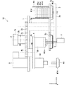
図1〜図2を参照して実施の形態1に係る組立装置について説明する。図1は、実施の形態1に係る組立装置の一部切り取り断面模式図である。図2は、実施の形態1に係る組立装置の要部の上面図である。なお、図1及び図2において、分かり易さのため、異なる回転角度の部品供給テーブル3(後述)と治具段取替テーブル4(後述)とを描画した。同様に、図1では、分かり易さのため、治具8a、8c(後述)の描画を省略した。また、図5〜7(後述)でも、同様に、治具8a、8c(後述)の描画を省略した。同様に、図2では、部品供給マガジン6a、6b、6c、6dの描画を省略した。
(Embodiment 1)
The assembly apparatus according to the first embodiment will be described with reference to FIGS. FIG. 1 is a partially cutaway cross-sectional schematic view of an assembling apparatus according to
図1及び図2に示すように、組立装置10は、ベース1と、回転動力部2と、部品供給テーブル3と、治具段取替テーブル4と、部品保持部5a、5b、5c、5dと、部品供給マガジン6a、6b、6c、6dと、部品供給部7と、治具8a、8b、8c、8dと、圧入サーボ9とを備える。組立装置10は、部品W1a、W1b、W1c、W1dを、被組立部品W2に圧入し、組立品を形成する。部品W1a、W1b、W1c、W1dは、例えば、カムピースであり、部品W1a、W1b、W1c、W1dは、形状や種類がそれぞれ異なっていてもよい。被組立部品W2は、例えば、オートマチックトランスミッションのクラッチドラムであり、組立品は、例えば、ピストンやバランサーである。組立装置10は、例えば、ピストンをドラムに圧入することによって、クラッチアセンブリを形成することができる。
As shown in FIGS. 1 and 2, the assembling
ベース1は、回転動力部2と、部品供給テーブル3と、治具段取替テーブル4とを回転可能に保持しており、回転動力部2と、部品供給テーブル3と、治具段取替テーブル4と互いの相対的な位置関係を決める。また、ベース1は、圧入サーボ9を保持する。
The
回転動力部2は、駆動部2aと、駆動軸2bと、平歯車2cとを備える。駆動部2aは、駆動軸2bを所定の方向に駆動させる装置であればよく、例えば、モータ等である。駆動軸2bは、その一端に平歯車2cを固定して保持しており、駆動部2aは、駆動軸2bを介して、平歯車2cを駆動軸2b回りに回転駆動させる。
The rotational power unit 2 includes a
部品供給テーブル3は、テーブル本体3aと、駆動軸3bと、平歯車3cとを備える。具体的には、駆動軸3bが、その一端にテーブル本体3aを支持し、その他端に平歯車3cを支持する。テーブル本体3aは、例えば、略円形状板であり、駆動軸3bがテーブル本体3aの中心軸から延びる。テーブル本体3aと平歯車3cとは、ベース1を挟むよう配置されている。平歯車3cは、回転動力部2の平歯車2cと噛み合っており、部品供給テーブル3は、平歯車2c、3cを介して、回転動力部2から駆動力を与えられ、駆動軸3b回りに回転駆動する。
The component supply table 3 includes a table
テーブル本体3aと、駆動軸3bとは、部品保持部5a、5b、5c、5dと、部品供給マガジン6a、6b、6c、6dとを支持する。部品保持部5a、5b、5c、5dと、部品供給マガジン6a、6b、6c、6dとは、それぞれ、部品W1a、W1b、W1c、W1dに応じた形状を有するとよい。部品保持部5a、5b、5c、5dと、部品供給マガジン6a、6b、6c、6dとは、駆動軸3bを中心とした同一の円上に配置される。部品保持部5a、5b、5c、5dとは、隣り合う部品保持部同士との距離が均等になるとよく、部品供給マガジン6a、6b、6c、6dとは、隣り合う部品供給マガジン同士との距離が均等になるとよい。部品保持部5a、5b、5c、5dは、駆動軸3b回りに回転可能に設けられている一方、部品供給マガジン6a、6b、6c、6dは、固定して設けられている。
The
部品保持部5a、5b、5c、5dは、部品W1a、W1b、W1c、W1dをそれぞれ保持しており、例えば、部品W1a、W1b、W1c、W1dをそれぞれ包含する凹形状を有する。部品供給マガジン6a、6b、6c、6dは、それぞれ複数の部品W1a、W1b、W1c、W1dを保持しており、例えば、積層した部品W1a、W1b、W1c、W1dを包囲する筒形状を有する。テーブル本体3aが回転することによって、部品供給マガジン6a、6b、6c、6dは、それぞれ、部品W1a、W1b、W1c、W1dを部品保持部5a、5b、5c、5dに供給する。具体的には、部品保持部5aの凹形状の深さを、部品W1aの厚みと略同じにする。これによって、テーブル本体3aが回転した場合、部品供給マガジン6aの内側において積層した部品W1aのうち最下層の部品W1aが、積層した部品W1aから1つ切出されるように、部品供給マガジン6aの内側から部品保持部5aへ移動する。同様に、部品W1b、W1c、W1dの厚みを、部品W1bの厚みと略同じに調整しつつ、部品保持部5b、5c、5dの凹形状の深さを、それぞれ部品W1aの厚みと略同じに調整するとよい。
The
治具段取替テーブル4は、テーブル本体4aと、駆動軸4bと、平歯車4cとを備える。平歯車4cは、回転動力部2の平歯車2cと噛み合っており、治具段取替テーブル4は、平歯車3c、4cを介して、回転動力部2から駆動力を与えられ、駆動軸4b回りに回転駆動する。上記した通り、平歯車2cは、駆動軸3bとも噛み合っているため、駆動軸3bと駆動軸4bとを連結する。具体的には、駆動軸4bが、その一端にテーブル本体4aを支持し、その他端に平歯車4cを支持する。テーブル本体4aは、例えば、略円形状板であり、駆動軸4bがテーブル本体4aの中心軸から延びる。テーブル本体4aと平歯車4cとは、ベース1を挟むよう配置されている。
The jig setup replacement table 4 includes a
テーブル本体4aは、治具8a、8b、8c、8dを備え、治具8a、8b、8c、8dは、テーブル本体4aの部品保持部5a、5b、5c、5d側に配置され、具体的には、吊り下げられている。治具8a、8b、8c、8dは、テーブル本体4aにおいて駆動軸4bを中心とした同一の円上に配置されている。この円は、部品保持部5a、5b、5c、5dと、部品供給マガジン6a、6b、6c、6dとが配置された駆動軸3bを中心とした同一の円に接するとよい。
The
組立装置10を上面視した場合、具体的には、Z軸プラス側からマイナス側に向かってみた場合、部品供給部7は、部品供給テーブル3のテーブル本体3aと治具段取替テーブル4のテーブル本体4aとが重なり合う箇所に位置するとよい。図1に示す一例では、部品供給部7が、部品保持部5dに保持された部品W1dを、部品保持部5dから治具8dに供給する。テーブル本体3aが回転することによって、部品W1a、W1b、W1cをそれぞれ部品供給部7近傍に移動させて、部品供給部7が、部品W1dと同様に、部品W1a、W1b、W1cについても、それぞれ部品保持部5a、5b、5cから治具8a、8b、8cに供給する。
When the
圧入サーボ9は、治具8bを押出し、治具8bに取り付けられた部品W1bを、被組立部品W2に圧入させる。同様に、駆動軸4bが回転することによって治具8a、8c、8dのそれぞれを圧入サーボ9近傍に移動させた後、圧入サーボ9は、治具8a、8c、8dのそれぞれを押出して、部品W1a、W1c、W1dのそれぞれを被組立部品W2に圧入させる。この圧入のため、必要に応じて、被組立部品W2を治具8a、8b、8c、8dのそれぞれに対して、接触させ、接近させ又は離間させてもよい。
The press-fitting
(動作の一例)
次に、図2〜図4を参照して、回転動力部2が駆動軸2bを回転させた動作の一例について説明する。図3及び図4では、分かり易くするため、テーブル本体3a、4a同士が、xy平面上、離間しているように描画されているが、実際には、図2に示すように、xy平面上、重なり合うように見える位置にあることに留意する。図3及び図4は、実施の形態1に係る組立装置の要部の動作を示す図である。
(Example of operation)
Next, an example of the operation in which the rotational power unit 2 rotates the
図3に示すように、部品保持部5a、5b、5c、5dが、それぞれ部品供給マガジン6a、6b、6c、6dに位置するように、部品供給テーブル3のテーブル本体3aは、駆動軸3bを中心として所定の角度にある場合がある。
As shown in FIG. 3, the table
図2及び図4に示すように、回転動力部2が駆動軸2bを回転させることによって、部品供給テーブル3のテーブル本体3aを、駆動軸3bを中心に時計回りに45°回転させる。すると、治具段取替テーブル4のテーブル本体4aが、駆動軸4bを中心に反時計回りに45°回転する。これによって、治具8dと、部品保持部5dとが部品供給部7(図1参照)に接近する。治具8dと、部品保持部5dと、部品供給部7とは、同一の仮想軸(ここでは、Z軸に沿う軸Z1)上に並ぶとよい。
As shown in FIGS. 2 and 4, the rotary power unit 2 rotates the
さらに、部品供給テーブル3のテーブル本体3aを、駆動軸2bを中心に時計回りに回転させることによって、治具8cと部品保持部5cとが部品供給部7(図1参照)近傍に位置する。さらに、このような回転を続けると、治具8bと部品保持部5bとの一組、治具8aと部品保持部5aとの一組が、この順に、部品供給部7近傍に位置し、再び、治具8dと、部品保持部5dとが部品供給部7近傍に位置する。
Further, by rotating the table
(部品供給方法)
次に、図5〜図7を用いて、組立装置10を用いた部品供給方法の一例について説明する。なお、以下に記載する部品供給方法の一例では、部品W1b、W1dを交互に連続して供給する。図5〜図7は、組み立て方法の1つのステップを示す図である。
(Parts supply method)
Next, an example of a component supply method using the
部品W1dと治具8dとを、部品供給部7近傍に回転移動させる(段取位置移動ステップST1)。具体的には、回転動力部2の平歯車2cを駆動させ、テーブル本体3a、4aを同期して180°回転させることによって、部品W1dと治具8dとを部品供給部7を通過する仮想軸(ここでは、Z軸に沿う軸)上に位置させる。
The component W1d and the
続いて、図5に示すように、部品W1dを治具8dに取り付ける(段取りステップST2)。具体的には、部品供給部7が部品W1dを押し上げて、部品保持部5dから上方へ移動させ、治具8dの所定位置、例えば、突起部に押し付けることによって、取り付ける。
Subsequently, as shown in FIG. 5, the component W1d is attached to the
続いて、図6に示すように、部品W1dを治具8dに取り付けたまま、治具8dを被組立部品W2へ移動させる(圧入位置移動ステップST3)。具体的には、上記した駆動によって、回転動力部2(図2参照)の平歯車2cを駆動させ、テーブル本体3a、4aを180°同期して回転させることによって、部品W1dと治具8dとを接近させる。具体的には、部品W1dと治具8dとを、被組立部品W2近傍、被組立部品W2を通過する仮想軸(ここでは、Z軸に沿う軸Z1)上に位置させるとともに、部品W1bと治具8bとを部品供給部7を通過する仮想軸上に位置させる。
Subsequently, as shown in FIG. 6, the
最後に、図7に示すように、部品W1dを被組立部品W2に圧入する(圧入ステップST4)。この圧入を行ないつつ、部品W1bを治具8bに取り付ける。具体的には、段取りステップST2と同様に、部品供給部7が部品W1bを押し上げて、部品保持部5bから上方へ移動させ、治具8bの所定位置、例えば、突起部に押し付けることによって、取り付ける。
Finally, as shown in FIG. 7, the component W1d is press-fitted into the assembly target component W2 (press-fitting step ST4). While performing this press fitting, the component W1b is attached to the
以上、段取位置移動ステップST1〜圧入ステップST4を順次繰り返すことによって、部品W1b、W1dを交互に被組立部品W2に圧入することができ、組立品を形成することができる。このような場合、操作者の手を用いることなく、異なる部品W1b、W1dを治具8b、8dに取り付けることができる。そのため、部品W1b、W1dのそれぞれに応じた治具8b、8dに、部品W1b、W1dを取り付けて、かつ部品W1b、W1dの供給を自動で行い、組立品を組み立てることができる。しかも、連続して部品W1b、W1dを交互に被組立部品W2に圧入し、多数の組立品を形成することができる。
As described above, by sequentially repeating the setup position moving step ST1 to the press-fitting step ST4, the parts W1b and W1d can be alternately press-fitted into the assembly target part W2, and an assembly can be formed. In such a case, different parts W1b and W1d can be attached to the
(組立装置の一変形例)
次に、図8及び図9を参照して、組立装置10(図1参照)の一変形例である組立装置20について説明する。図8は、実施の形態1に係る組立装置の一変形例を示す斜視図である。図9は、実施の形態1に係る組立装置の一変形例を示す側面図である。組立装置20は、平歯車を必要とすることなく、回転動力部23d、24dを2つ備えるところを除いて、組立装置10と同じ構成を有する。組立装置20の各構成は、同じ組立装置10の構成と対応するように付番した。
(One variation of assembly device)
Next, with reference to FIGS. 8 and 9, an
図8及び図9に示すように、組立装置20は、部品供給テーブル23と、治具段取替テーブル24とを備える。
As shown in FIGS. 8 and 9, the assembling
部品供給テーブル23は、テーブル本体23aと、駆動軸23bと、回転動力部23dとを備える。回転動力部23dは、駆動軸23b回りにテーブル本体23aを回転駆動させる。
The component supply table 23 includes a table body 23a, a
治具段取替テーブル24は、テーブル本体24aと、駆動軸24bと、回転動力部24dとを備える。回転動力部24dは、駆動軸24b回りにテーブル本体24aを回転駆動させる。
The jig setup replacement table 24 includes a table
回転動力部23dと回転動力部24dとは、テーブル本体23aとテーブル本体24aとを独立して回転駆動させることができる。これによって、複数の部品W21(図示略)のうち、所定の部品を選択し、選択した部品を切出すように、部品供給マガジン26の内側から部品保持部25へ移動させることができる。また、複数種類の部品W21(図示略)のうち、種類の異なる所定の部品を選択して、それぞれに対応する治具に取り付け、被組立部品W22に圧入し、これらを繰り返して、種類の異なる組立品を生産することができる。すなわち、1つの組立装置20を用いて複数種類の組立品を生産する、混流生産を行うことができる。
The
なお、本発明は上記実施の形態に限られたものではなく、趣旨を逸脱しない範囲で適宜変更することが可能である。例えば、上記した組立装置10を用いた部品供給方法では、部品W1b、W1dを順に連続して供給したが、部品W1a、W1b、W1c、W1dをこの順に連続して供給してもよい。
Note that the present invention is not limited to the above-described embodiment, and can be changed as appropriate without departing from the spirit of the present invention. For example, in the component supply method using the
100 組立装置
1 ベース
2 回転動力部
2a 駆動部 2c 平歯車
3 部品供給テーブル 4 治具段取替テーブル
8a、8b、8c、8d 治具
W1a、W1b、W1c、W1d 部品 W2 被組立部品
100
Claims (1)
前記複数種類の部品に対応する複数種類の治具を保持しつつ、第2の回転軸回りに回転可能に設けられた治具段取替テーブルと、
前記部品供給テーブルと、前記治具段取替テーブルとを連結する平歯車と、
前記平歯車に駆動力を与える駆動部と、を備える組立装置であって、
前記駆動部が前記平歯車を回転駆動させることによって、前記部品供給テーブルと前記治具段取替テーブルとが、同期して回転し、
前記部品供給テーブルに保持された部品と、前記部品供給テーブルに保持された前記部品に応じた前記治具とを互いに接近させて、
前記部品を、前記部品に応じた前記治具に取り付ける、
組立装置。 A component supply table provided to be rotatable around the first rotation axis while holding a plurality of types of components;
While holding a plurality of types of jigs corresponding to the plurality of types of components, a jig setup replacement table provided rotatably around the second rotation axis;
A spur gear connecting the component supply table and the jig setup replacement table;
An assembly device comprising: a drive unit that applies a drive force to the spur gear;
When the drive unit rotates the spur gear, the component supply table and the jig setup replacement table rotate synchronously,
The parts held on the parts supply table and the jig corresponding to the parts held on the parts supply table are brought close to each other,
The part is attached to the jig corresponding to the part.
Assembly equipment.
Priority Applications (1)
| Application Number | Priority Date | Filing Date | Title |
|---|---|---|---|
| JP2017100244A JP6737233B2 (en) | 2017-05-19 | 2017-05-19 | Assembly equipment |
Applications Claiming Priority (1)
| Application Number | Priority Date | Filing Date | Title |
|---|---|---|---|
| JP2017100244A JP6737233B2 (en) | 2017-05-19 | 2017-05-19 | Assembly equipment |
Publications (2)
| Publication Number | Publication Date |
|---|---|
| JP2018192590A true JP2018192590A (en) | 2018-12-06 |
| JP6737233B2 JP6737233B2 (en) | 2020-08-05 |
Family
ID=64568777
Family Applications (1)
| Application Number | Title | Priority Date | Filing Date |
|---|---|---|---|
| JP2017100244A Expired - Fee Related JP6737233B2 (en) | 2017-05-19 | 2017-05-19 | Assembly equipment |
Country Status (1)
| Country | Link |
|---|---|
| JP (1) | JP6737233B2 (en) |
Citations (6)
| Publication number | Priority date | Publication date | Assignee | Title |
|---|---|---|---|---|
| JPS59214525A (en) * | 1983-05-23 | 1984-12-04 | Fujitsu Ltd | Parts assembling device |
| JPS62114289A (en) * | 1985-11-14 | 1987-05-26 | 松下電器産業株式会社 | Mounting of electronic parts and apparatus for the same |
| JPH0557656A (en) * | 1991-08-30 | 1993-03-09 | Olympus Optical Co Ltd | Robot hand |
| JP2001334419A (en) * | 2000-05-26 | 2001-12-04 | Furukawa Battery Co Ltd:The | Assembly device |
| JP2004195556A (en) * | 2002-12-16 | 2004-07-15 | Kyoto Seisakusho Co Ltd | Assembling arrangement |
| JP2008213659A (en) * | 2007-03-02 | 2008-09-18 | Shoei Bijutsu:Kk | Turntable device |
-
2017
- 2017-05-19 JP JP2017100244A patent/JP6737233B2/en not_active Expired - Fee Related
Patent Citations (6)
| Publication number | Priority date | Publication date | Assignee | Title |
|---|---|---|---|---|
| JPS59214525A (en) * | 1983-05-23 | 1984-12-04 | Fujitsu Ltd | Parts assembling device |
| JPS62114289A (en) * | 1985-11-14 | 1987-05-26 | 松下電器産業株式会社 | Mounting of electronic parts and apparatus for the same |
| JPH0557656A (en) * | 1991-08-30 | 1993-03-09 | Olympus Optical Co Ltd | Robot hand |
| JP2001334419A (en) * | 2000-05-26 | 2001-12-04 | Furukawa Battery Co Ltd:The | Assembly device |
| JP2004195556A (en) * | 2002-12-16 | 2004-07-15 | Kyoto Seisakusho Co Ltd | Assembling arrangement |
| JP2008213659A (en) * | 2007-03-02 | 2008-09-18 | Shoei Bijutsu:Kk | Turntable device |
Also Published As
| Publication number | Publication date |
|---|---|
| JP6737233B2 (en) | 2020-08-05 |
Similar Documents
| Publication | Publication Date | Title |
|---|---|---|
| KR101326828B1 (en) | Rotating module for clamping device | |
| CN103204379B (en) | Handling device and robot system | |
| JP6322014B2 (en) | Clamping device | |
| US20180375409A1 (en) | Stator manufacturing method and device therefor | |
| JP2007518032A (en) | Layout and method for camshaft manufacturing | |
| CN102357873B (en) | Reconfigurable tool for pipeline integral welding | |
| KR20150109248A (en) | Rotary work device | |
| JP2007211975A (en) | Manufacturing method of reduction gear and robot incorporating such reduction gear | |
| KR20040019918A (en) | Polishing machine | |
| US11478867B2 (en) | Machining device for duplex gear of high-precision reducer for robot, and use method thereof | |
| JP2021061646A (en) | Rotor assembly jig and rotor assembly method using the same | |
| JP2018192590A (en) | Assembly device | |
| CN110421367A (en) | A kind of Machining of Shaft-type Parts automatic fixture | |
| CN108422179A (en) | Automatically screw device is beaten | |
| CN113664315B (en) | Production line and brazing process of air conditioner tubing assembly | |
| JP2009035760A (en) | Device for eccentrically driving heating coil body in induction heating apparatus | |
| JP2008000849A (en) | Rotating fixture mechanism | |
| CN110449798A (en) | A kind of quick positioning welding machine people for automobile exhaust pipe | |
| CN110625396A (en) | 360 processingequipment and drilling of degree rotation multi-angle are attacked tooth equipment | |
| JPWO2018198648A1 (en) | Manufacturing method of scroll compressor | |
| CN107971583A (en) | A kind of RV retarders cycloidal-pin wheel frock and processing method | |
| CN112032273A (en) | Transmission structure and speed reducer | |
| JP2021175337A (en) | Stator manufacturing device | |
| JP2020089212A (en) | Adhesive coating device and adhesive coating method | |
| JP2020124777A (en) | Workpiece holder |
Legal Events
| Date | Code | Title | Description |
|---|---|---|---|
| A621 | Written request for application examination |
Free format text: JAPANESE INTERMEDIATE CODE: A621 Effective date: 20190823 |
|
| A977 | Report on retrieval |
Free format text: JAPANESE INTERMEDIATE CODE: A971007 Effective date: 20200603 |
|
| TRDD | Decision of grant or rejection written | ||
| A01 | Written decision to grant a patent or to grant a registration (utility model) |
Free format text: JAPANESE INTERMEDIATE CODE: A01 Effective date: 20200616 |
|
| A61 | First payment of annual fees (during grant procedure) |
Free format text: JAPANESE INTERMEDIATE CODE: A61 Effective date: 20200629 |
|
| R151 | Written notification of patent or utility model registration |
Ref document number: 6737233 Country of ref document: JP Free format text: JAPANESE INTERMEDIATE CODE: R151 |
|
| LAPS | Cancellation because of no payment of annual fees |