JP2018191237A - Wireless communication device - Google Patents
Wireless communication device Download PDFInfo
- Publication number
- JP2018191237A JP2018191237A JP2017094593A JP2017094593A JP2018191237A JP 2018191237 A JP2018191237 A JP 2018191237A JP 2017094593 A JP2017094593 A JP 2017094593A JP 2017094593 A JP2017094593 A JP 2017094593A JP 2018191237 A JP2018191237 A JP 2018191237A
- Authority
- JP
- Japan
- Prior art keywords
- wireless communication
- radio
- signal
- unit
- reception
- Prior art date
- Legal status (The legal status is an assumption and is not a legal conclusion. Google has not performed a legal analysis and makes no representation as to the accuracy of the status listed.)
- Granted
Links
Images

Landscapes
- Transceivers (AREA)
- Telephone Function (AREA)
Abstract
【課題】無線通信装置において、受信専用のアンテナによる無線信号の受信精度の低下を抑制する。【解決手段】無線通信装置は、無線送信部と第1無線受信部とを有する1つ以上の無線通信部であって、無線送信部による無線信号の送信が行われている場合に、該送信が行われていることを示す送信実行信号を出力する無線通信部と、無線通信のために電波の送受信を行う1つ以上の第1アンテナと、無線信号の受信を行う第2無線受信部と、第2無線受信部による無線信号の受信のために、電波の受信を行う第2アンテナと、送信実行信号又は無効化実行信号を入力した場合に、第2アンテナで受信された電波に基づく無線信号の受信を、無効化する受信無効化部と、を備える。【選択図】図1PROBLEM TO BE SOLVED: To suppress a decrease in reception accuracy of a wireless signal by a reception-only antenna in a wireless communication device. A wireless communication device is one or more wireless communication units having a wireless transmission unit and a first wireless reception unit, and when the wireless transmission unit transmits a wireless signal, the transmission is performed. A wireless communication unit that outputs a transmission execution signal indicating that is being performed, one or more first antennas that transmit and receive radio waves for wireless communication, and a second wireless reception unit that receives wireless signals. , Radio based on the radio wave received by the second antenna when the transmission execution signal or invalidation execution signal is input to the second antenna that receives the radio wave for the reception of the radio signal by the second radio reception unit It includes a reception invalidation unit that invalidates the reception of a signal. [Selection diagram] Fig. 1
Description
本発明は、無線通信装置に関する。 The present invention relates to a wireless communication apparatus.
無線通信装置として、無線信号を送受信するためのアンテナ(以下、「送受信用アンテナ」と呼ぶ)とは別に、無線信号の受信専用のアンテナ(以下、「受信専用アンテナ」と呼ぶ)を備える無線通信装置が提案されている。例えば、特許文献1では、CDMA(Code Division Multiple Access)2000により無線通信を行う第1のモードと、GSM(Global System for Mobile communications:登録商標)により無線通信を行う第2のモードとを有し、第1のモードでは送受信用アンテナと受信専用アンテナの両方を用い、第2のモードでは送受信用アンテナを用いる携帯電話端末が提案されている。このように受信専用アンテナを備える無線通信装置としては、上述の携帯電話端末以外にも、例えば、周囲において使用中のチャンネルを検出したり、DFS(Dynamic Frequency Selection)機能を実現するために気象レーダーの干渉波を検出したり、といった周囲の無線通信環境を検索するための受信専用アンテナを備えた無線LANアクセスポイント装置などが挙げられる。
As a wireless communication device, wireless communication provided with an antenna dedicated to receiving radio signals (hereinafter referred to as “reception dedicated antenna”) separately from an antenna for transmitting and receiving wireless signals (hereinafter referred to as “transmission / reception antenna”). A device has been proposed. For example,
しかし、送受信用アンテナを用いた無線信号の送信と、受信専用アンテナを用いた無線信号の受信とが同時に行われると、無線通信装置は、自らが出力する無線信号を、受信専用アンテナによって高レベルの信号として受信してしまう。このため、本来、受信専用アンテナで受信(検出)すべき無線信号、例えば、他の無線通信装置が出力する無線信号や気象レーダーの信号を正確に受信して復調することができないという問題がある。このため、受信専用のアンテナを送受信用のアンテナとは別に備える無線通信装置において、受信専用のアンテナによる無線信号の受信精度の低下を抑制可能な技術が望まれている。 However, if transmission of a radio signal using a transmission / reception antenna and reception of a radio signal using a reception-dedicated antenna are performed at the same time, the radio communication device transmits a radio signal output by itself by the reception-dedicated antenna to a high level It will be received as a signal. For this reason, there is a problem that a radio signal that should be received (detected) by a reception-only antenna, for example, a radio signal output by another radio communication device or a weather radar signal cannot be accurately received and demodulated. . For this reason, there is a demand for a technique that can suppress a decrease in the reception accuracy of a radio signal by a reception-dedicated antenna in a wireless communication apparatus that includes a reception-dedicated antenna separately from a transmission / reception antenna.
本発明は、上述の課題の少なくとも一部を解決するためになされたものであり、以下の形態として実現することが可能である。 SUMMARY An advantage of some aspects of the invention is to solve at least a part of the problems described above, and the invention can be implemented as the following forms.
(1)本発明の一形態によれば、無線通信装置が提供される。この無線通信装置は、無線送信部と第1無線受信部とを有する1つ以上の無線通信部であって、前記無線送信部による無線信号の送信が行われている場合に、該送信が行われていることを示す送信実行信号を出力する無線通信部と;前記無線通信部による無線通信のために電波の送受信を行う1つ以上の第1アンテナと;無線信号の送信と無線信号の受信とのうち、無線信号の受信を行う第2無線受信部と;前記第2無線受信部による無線信号の受信のために、電波の送信と電波の受信とのうち、電波の受信を行う第2アンテナと;前記送信実行信号又は前記送信実行信号に基づき生成される無効化実行信号を入力した場合に、前記第2アンテナで受信された電波に基づく無線信号の受信を、無効化する受信無効化部と;を備える。 (1) According to an aspect of the present invention, a wireless communication device is provided. The wireless communication device is one or more wireless communication units each having a wireless transmission unit and a first wireless reception unit, and performs transmission when a wireless signal is transmitted by the wireless transmission unit. A wireless communication unit that outputs a transmission execution signal indicating that the wireless communication unit is connected; one or more first antennas that transmit and receive radio waves for wireless communication by the wireless communication unit; transmission of wireless signals and reception of wireless signals A second radio receiving unit that receives a radio signal; and a second radio receiving unit that receives a radio signal among a radio wave transmission and a radio wave reception for receiving a radio signal by the second radio receiving unit. A reception invalidation that invalidates reception of a radio signal based on a radio wave received by the second antenna when an antenna and an invalidation execution signal generated based on the transmission execution signal are input. And a section.
この形態の無線通信装置によれば、送信実行信号又は送信実行信号に基づき生成される無効化実行信号が受信無効化部に入力された場合に、第2アンテナで受信された電波に基づく無線信号の受信を無効化するので、無線送信部により無線信号を送信している間に、第2アンテナで受信された電波に基づく無線信号の受信を無効化できる。言い換えると、無線送信部により無線信号を送信していない間において第2アンテナで受信された電波に基づき無線信号を受信するので、第2アンテナによる無線信号の受信精度の低下を抑制できる。 According to the wireless communication apparatus of this aspect, when the invalidation execution signal generated based on the transmission execution signal or the transmission execution signal is input to the reception invalidation unit, the radio signal based on the radio wave received by the second antenna Therefore, the reception of the wireless signal based on the radio wave received by the second antenna can be disabled while the wireless transmission unit transmits the wireless signal. In other words, since the radio signal is received based on the radio wave received by the second antenna while the radio signal is not transmitted by the radio transmission unit, it is possible to suppress a decrease in radio signal reception accuracy by the second antenna.
(2)上記形態の無線通信装置において、複数の前記無線通信部と;複数の前記無線通信部がそれぞれ出力する前記送信実行信号を入力し、前記無効化実行信号を出力するOR回路と;を更に備え;前記受信無効化部は、前記OR回路から出力される前記無効化実行信号を入力してもよい。この形態の無線通信装置によれば、受信無効化部は、OR回路から出力される無効化実行信号を入力するので、複数の無線通信部のいずれかの無線通信部において無線信号が送信されている間に、第2アンテナで受信された電波に基づく無線信号の受信を無効化でき、第2アンテナによる無線信号の受信精度の低下をより確実に抑制できる。 (2) In the wireless communication device of the above aspect, a plurality of the wireless communication units; an OR circuit that inputs the transmission execution signals output from each of the plurality of wireless communication units and outputs the invalidation execution signal; The reception invalidation unit may further receive the invalidation execution signal output from the OR circuit. According to the wireless communication device of this aspect, the reception invalidation unit receives the invalidation execution signal output from the OR circuit, so that the wireless signal is transmitted from any one of the plurality of wireless communication units. In the meantime, the reception of the radio signal based on the radio wave received by the second antenna can be invalidated, and the deterioration of the reception accuracy of the radio signal by the second antenna can be more reliably suppressed.
(3)上記形態の無線通信装置において、前記無線通信部は、半二重通信により、無線通信を実行してもよい。この形態の無線通信装置によれば、半二重通信を行う構成において、第2アンテナによる無線信号の受信精度の低下を抑制できる。 (3) In the wireless communication device of the above aspect, the wireless communication unit may execute wireless communication by half-duplex communication. According to the wireless communication device of this aspect, it is possible to suppress a decrease in the reception accuracy of the wireless signal by the second antenna in the configuration for performing half-duplex communication.
(4)上記形態の無線通信装置において、前記無線送信部は、信号出力部と、前記信号出力部からの出力信号を増幅する増幅器と、前記増幅器による増幅動作を指示する送信制御部と、を有し;前記送信実行信号は、前記送信制御部が前記増幅動作を前記増幅器に指示するための信号と一致してもよい。この形態の無線通信装置によれば、送信実行信号は、送信制御部が増幅動作を増幅器に指示するための信号と一致するので、送信実行信号を出力するための専用の構成(信号出力のための専用機能および専用配線)を省略でき、無線通信装置の製造コストを抑えることができる。 (4) In the wireless communication device of the above aspect, the wireless transmission unit includes a signal output unit, an amplifier that amplifies an output signal from the signal output unit, and a transmission control unit that instructs an amplification operation by the amplifier. The transmission execution signal may coincide with a signal for the transmission control unit to instruct the amplifier to perform the amplification operation. According to the wireless communication apparatus of this aspect, the transmission execution signal matches the signal for the transmission control unit to instruct the amplifier to perform the amplification operation, and therefore, a dedicated configuration for outputting the transmission execution signal (for signal output) The dedicated function and dedicated wiring) can be omitted, and the manufacturing cost of the wireless communication device can be reduced.
(5)上記形態の無線通信装置において、前記受信無効化部は、前記第2無線受信部を前記第2アンテナに電気的に接続するための第1導線と;前記第2無線受信部を第1終端抵抗に電気的に接続するための第2導線と;前記第2無線受信部を、前記第1導線と前記第2導線とのうちのいずれかに選択的に接続するための第1スイッチ回路と;を有し、前記無効化実行信号を入力した場合に、前記第2無線受信部と前記第2導線とが電気的に接続するように前記第1スイッチ回路を動作させてもよい。この形態の無線通信装置によれば、無効化実行信号を入力した場合に、第2無線受信部と第2導線とが電気的に接続するように第1スイッチ回路が動作されるので、無線信号が送信されている間に、第2無線受信部を第1終端抵抗に電気的に接続でき、無線信号の受信を無効化できる。 (5) In the radio communication apparatus according to the above aspect, the reception invalidation unit includes a first conductor for electrically connecting the second radio reception unit to the second antenna; A second conductor for electrically connecting to one termination resistor; a first switch for selectively connecting the second wireless receiver to either the first conductor or the second conductor And when the invalidation execution signal is input, the first switch circuit may be operated so that the second wireless reception unit and the second conductor are electrically connected. According to the wireless communication device of this aspect, when the invalidation execution signal is input, the first switch circuit is operated so that the second wireless reception unit and the second conductor are electrically connected. Can be electrically connected to the first terminator and the reception of the radio signal can be invalidated.
(6)上記形態の無線通信装置において、前記受信無効化部は、前記第2アンテナを第2終端抵抗に電気的に接続するための第3導線と;前記第2アンテナを、前記第1導線と前記第3導線とのうちのいずれかに選択的に接続するための第2スイッチ回路と;を有し、前記無効化実行信号を入力した場合に、前記第2アンテナと前記第3導線とが電気的に接続するように前記第2スイッチ回路を動作させてもよい。この形態の無線通信装置によれば、無効化実行信号を入力した場合に、第2アンテナと第3導線とが電気的に接続するように第2スイッチ回路が動作されるので、無線信号が送信されている間に、第2アンテナを第2終端抵抗に電気的に接続できる。このため、第1アンテナから出力された電波が第2アンテナに入力されたとしても、かかる電波が第2無線受信部に受信されることを抑制できる。加えて、第1アンテナから出力された電波が第2アンテナに入力されたとしても、かかる入力電波のエネルギーを第2終端抵抗で吸収でき、単純に断線させた場合に懸念される「反射波が第2アンテナから出力すること」を抑制できる。 (6) In the wireless communication device according to the above aspect, the reception invalidation unit includes a third conductor for electrically connecting the second antenna to a second termination resistor; and the second antenna is connected to the first conductor. And a second switch circuit for selectively connecting to any one of the third conductor and the second antenna and the third conductor when the invalidation execution signal is input. The second switch circuit may be operated so as to be electrically connected. According to the wireless communication device of this aspect, when the invalidation execution signal is input, the second switch circuit is operated so that the second antenna and the third conductor are electrically connected, so that the wireless signal is transmitted. During this time, the second antenna can be electrically connected to the second termination resistor. For this reason, even if the electric wave output from the 1st antenna is input into the 2nd antenna, it can suppress that this electric wave is received by the 2nd wireless receiving part. In addition, even if the radio wave output from the first antenna is input to the second antenna, the energy of the input radio wave can be absorbed by the second terminal resistor, and there is a concern that “the reflected wave is “Output from the second antenna” can be suppressed.
(7)上記形態の無線通信装置において、前記第2無線受信部は、前記無線通信部による無線通信のための周囲の無線通信環境の確認のために前記第2アンテナを用いた無線信号の受信を行ってもよい。この形態の無線通信装置によれば、無線通信装置の周囲の無線通信環境を精度良く確認できる。 (7) In the wireless communication device of the above aspect, the second wireless reception unit receives a wireless signal using the second antenna for checking a surrounding wireless communication environment for wireless communication by the wireless communication unit. May be performed. According to the wireless communication device of this aspect, the wireless communication environment around the wireless communication device can be confirmed with high accuracy.
本発明は、互いに同じ周波数帯を利用する送受信装置と受信装置とを備える無線機器に関連する種々の形態で実現することも可能である。例えば、無線LANアクセスポイント装置や無線LANクライアント装置などの無線LAN装置や、無線信号の送受信方法や、かかる方法を実現するためのコンピュータプログラムや、かかるコンピュータプログラムを記録した一時的ではないコンピュータ読み取り可能な記録媒体等の形態で実現することができる。 The present invention can also be realized in various forms related to a wireless device including a transmission / reception device and a reception device that use the same frequency band. For example, a wireless LAN device such as a wireless LAN access point device or a wireless LAN client device, a wireless signal transmission / reception method, a computer program for realizing the method, or a non-temporary computer readable recording of the computer program It can be realized in the form of a simple recording medium.
A.第1実施形態:
A1.装置構成:
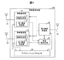
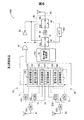
図1は、本発明の一実施形態としての無線通信装置の機能を示すブロック図である。本実施形態において、無線通信装置100は、無線LANアクセスポイント装置として機能する。無線通信装置100は、2つの無線通信部10、20と、第2無線受信部30と、受信無効化部40と、アプリケーションプロセッサ50と、2つの第1アンテナ91、92と、第2アンテナ93とを備える。
A. First embodiment:
A1. Device configuration:
FIG. 1 is a block diagram showing functions of a wireless communication apparatus as an embodiment of the present invention. In the present embodiment, the
無線通信部10は、無線送信部11と、第1無線受信部12とを備える。無線送信部11は、アプリケーションプロセッサ50で実行されるWebサーバアプリケーションやユーザインターフェイス用のアプリケーション等の各種アプリケーションからデータを受け取ると、MAC(Media Access Control)データを作成し、さらに、かかるMACデータに基づき無線信号を生成して第1アンテナ91を介して出力する。第1無線受信部12は、第1アンテナ91を介して受信する電波からMACデータを形成し、さらに、かかるMACデータに基づきアプリケーションデータを生成してアプリケーションプロセッサ50に出力する。無線通信部20は、無線通信部10と同様な構成を有する。具体的には、無線通信部20は、無線送信部11と同じ機能を有する無線送信部21と、第1無線受信部12と同じ機能を有する第1無線受信部22と、を備える。本実施形態において、2つの無線通信部10、20は、いずれもIEEE802.11nに規定された2.4GHz帯の周波数帯域を用いた無線通信を行う。本実施形態では、2つの無線通信部10、20は、いずれも単一のRF(Radio Frequency)回路の一部として構成されている。
The
第2無線受信部30は、無線通信装置100の周囲の無線通信環境、具体的には、2.4GHz帯の各チャンネルを利用した他の通信の有無を検出するために、無線信号の送信と無線信号の受信とのうち、無線信号の受信を行う。第2無線受信部30は、検出した他の通信における使用チャンネルを、図示しない主制御部に通知する。主制御部は、かかる通知を受信すると、使用チャンネルの変更を各無線通信部10、20に通知する。各無線通信部10、20は、通知された使用チャンネルを除く他のチャンネルを、無線通信に使用するチャンネルに設定する。上述の図示しない制御部は、無線通信装置100のうち、アプリケーションプロセッサ50を除く機能部により実現され、無線LANアクセスポイントとしての機能全体を制御する。
The second
受信無効化部40は、所定の条件の下、第2無線受信部30による無線信号の受信を無効化する。換言すると、受信無効化部40は、所定の条件の下、後述の第2アンテナ93で受信された電波に基づく無線信号の受信を無効化する。かかる無線信号の無効化の具体的な方法、および無効化を実行するための条件については、後述する。
The
アプリケーションプロセッサ50は、無線通信装置100が提供する無線LANアクセスポイントとしての機能に対して付加的な機能を提供する。例えば、図示しない表示部に表示させるメニュー画面の作成などのユーザインターフェイスを実現するための機能や、Webサーバとしての機能などを実現する。
The
第1アンテナ91は、無線通信部10に電気的に接続されており、無線通信部10による無線通信のために電波の送受信を行う。第1アンテナ92は、無線通信部20に電気的に接続されており、無線通信部20による無線通信のために電波の送受信を行う。第2アンテナ93は、第2無線受信部30に電気的に接続されており、第2無線受信部30による無線信号の受信のために、電波の送信と電波の受信とのうち、電波の受信を行う。
The
本実施形態において、第1アンテナ91および第1アンテナ92は、MIMO(Multiple Input Multiple Output)を実現するために用いられている。すなわち、無線通信装置100では、各第1アンテナ91、92からそれぞれ異なるデータに基づく無線信号を同時に出力することにより、通信速度を向上させることができる。また、各無線通信部10、20は、半二重通信により無線通信を実行する。したがって、例えば、無線通信部10では、無線送信部11による第1アンテナ91を介した無線信号の受信と、第1無線受信部12による第1アンテナ91を介した無線信号の受信とが、短時間の間に切り替わりながら実行される。
In the present embodiment, the
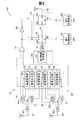
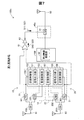
図2は、無線通信装置100の詳細構成を示すブロック図である。図2では、図1とは異なり、アプリケーションプロセッサ50を除く他の機能部の具体的な装置構成を示す。
FIG. 2 is a block diagram illustrating a detailed configuration of the
無線通信装置100は、2つの送受信切替スイッチ103、203と、2つの増幅器101、201と、2つのローノイズアンプ102、202と、第1ベースバンドプロセッサ(以下、「第1BBプロセッサ」と呼ぶ)150と、第2ベースバンドプロセッサ(以下、「第2BBプロセッサ」と呼ぶ)160と、OR回路61と、NOT回路62と、第1導線41と、第2導線42と、第3導線43と、第1スイッチ回路44と、第2スイッチ回路45と、上述の3つのアンテナ91〜93を備える。
The
送受信切替スイッチ103は、第1アンテナ91の接続先を増幅器101とローノイズアンプ102とのうちのいずれか一方に選択的に切り替える。同様に、送受信切替スイッチ203は、第1アンテナ92の接続先を増幅器201とローノイズアンプ202とのうちのいずれか一方に選択的に切り替える。各送受信切替スイッチ103、203は、図示しない導線により第1BBプロセッサ150に接続されている。各送受信切替スイッチ103、203の接続先の切替は、第1BBプロセッサ150からの指示に応じて実行される。
The transmission /
増幅器101は、いわゆる高周波パワーアンプに相当する。増幅器101は、第1BBプロセッサ150および送受信切替スイッチ103と電気的に接続されており、第1BBプロセッサ150から出力された無線信号を増幅して送受信切替スイッチ103に出力する。増幅器101は、後述する送信制御部152が出力するイネーブル信号を受信する場合に、無線信号の増幅を実行する。換言すると、イネーブル信号は、後述する送信制御部152が増幅動作を増幅器101に指示するための信号といえる。同様に、増幅器201もパワーアンプに相当し、第1BBプロセッサ150および送受信切替スイッチ203と電気的に接続されており、第1BBプロセッサ150から出力された無線信号を増幅して送受信切替スイッチ203に出力する。増幅器201は、後述する送信制御部156が出力するイネーブル信号を受信する場合に、無線信号の増幅を実行する。
The
ローノイズアンプ102は、送受信切替スイッチ103および第1BBプロセッサ150と電気的に接続されており、第1アンテナ91を介して受信する無線信号のうち、所定の周波数帯の信号を増幅して第1BBプロセッサ150に出力する。同様に、ローノイズアンプ202は、送受信切替スイッチ203および第1BBプロセッサ150と電気的に接続されており、第1アンテナ92を介して受信する無線信号のうち、所定の周波数帯の信号を増幅して第1BBプロセッサ150に出力する。
The
第1BBプロセッサ150は、図示しないメモリに予め記憶されている制御プログラムを実行することにより、信号出力部151、送信制御部152、受信制御部153、信号出力部155、送信制御部156、および受信制御部157として、それぞれ機能する。信号出力部151は、送信すべきデータをアナログ信号として出力する。送信制御部152は、信号出力部151からの出力信号を、増幅器101を用いて増幅させて第1アンテナ91から出力させる。このとき、送信制御部152は、増幅器101にイネーブル信号を送信することにより増幅器101に信号の増幅を指示する。受信制御部153は、第1アンテナ91を介した無線信号の受信を制御する。具体的には、受信制御部153は、第1アンテナ91を介して無線信号を受信しようとする場合、ローノイズアンプ102に対してイネーブル信号を送信し、第1アンテナ91から受信する無線信号を増幅させる。なお、増幅後の無線信号を受信した受信制御部153では、所定周波数帯の無線信号をフィルタする。信号出力部155は、上述の信号出力部151と同様な機能を有するので、その詳細な説明を省略する。また、送信制御部156は、上述の送信制御部152と同様な機能を有するので、その詳細な説明を省略する。また、受信制御部157は、上述の受信制御部153と同様な機能を有するので、その詳細な説明を省略する。なお、送信制御部152と増幅器101とは、上述の無線送信部11に相当する。また、受信制御部153とローノイズアンプ102とは上述の第1無線受信部12に、送信制御部156と増幅器201とは上述の無線送信部21に、受信制御部157とローノイズアンプ202とは上述の第1無線受信部22に、それぞれ相当する。
The
第2BBプロセッサ160は、図示しないメモリに予め記憶されている制御プログラムを実行することにより、上述の第2無線受信部30として機能する。
The
OR回路61の入力端子は、第1BBプロセッサ150と増幅器101との間の導線、および第1BBプロセッサ150と増幅器201との間の導線に、電気的に接続されている。したがって、OR回路61は、第1BBプロセッサ150から増幅器101に送信されるイネーブル信号、換言すると送信制御部152から出力されるイネーブル信号を入力する。同様に、OR回路61は、第1BBプロセッサ150から増幅器201に送信されるイネーブル信号、換言すると、送信制御部156から出力されるイネーブル信号を入力する。したがって、OR回路61からの出力信号は、送信制御部152と送信制御部156との少なくとも一方がイネーブル信号を送信している場合には、HIとなり、送信制御部152と送信制御部156とのいずれもイネーブル信号を送信していない場合には、LOとなる。OR回路61の出力端子は、NOT回路62と、第1スイッチ回路44と、第2スイッチ回路45とに電気的に接続されている。なお、第1BBプロセッサ150から2つの増幅器101、201に送信されるイネーブル信号は、課題を解決するための手段欄における送信実行信号の下位概念に相当する。また、OR回路61から出力されるHIの信号は、課題を解決するための手段欄における無効化実行信号の下位概念に相当する。
An input terminal of the
NOT回路62の入力端子は、OR回路61の出力端子に電気的に接続されている。したがって、送信制御部152と送信制御部156との少なくとも一方がイネーブル信号を送信している場合には、LOとなり、送信制御部152と送信制御部156とのいずれもイネーブル信号を送信していない場合には、HIとなる。NOT回路62の出力端子は、第1スイッチ回路44と、第2スイッチ回路45とに電気的に接続されている。
The input terminal of the
第1導線41は、第2BBプロセッサ160(第2無線受信部30)を第2アンテナ93に接続するための導線である。本実施形態において、第1導線41は、第1スイッチ回路44と第2スイッチ回路45とを電気的に接続する。第2導線42は、第2BBプロセッサ160(第2無線受信部30)を、第1終端抵抗401に電気的に接続するための導線である。第3導線43は、第2アンテナ93を、第2終端抵抗402に電気的に接続するための導線である。2つの終端抵抗401、402は、アンテナの代わりとなる終端機能を有し、無誘導抵抗器(高周波においてもL性、C性にならないように工夫された抵抗器)、ダミーロード(擬似負荷、擬似負荷抵抗)で構成されている。
The
第1スイッチ回路44は、ローノイズアンプ31を介して第2BBプロセッサ160と電気的に接続されている。また、第1スイッチ回路44は、第1導線41と、第2導線42とに電気的に接続されている。第1スイッチ回路44は、第2BBプロセッサ160(第2無線受信部30)を、第1導線41と第2導線42とのうちのいずれかに選択的に接続する。また、第1スイッチ回路44は、OR回路61の出力端子と、NOT回路62の出力端子とにそれぞれ電気的に接続されており、これらからの入力される信号に基づき、上述の接続状態を切り替える。具体的には、第1スイッチ回路44は、OR回路61からの入力信号がLOであり、且つ、NOT回路62からの入力信号がHIである場合に、第2BBプロセッサ160(第2無線受信部30)を第1導線41に接続する。また、第1スイッチ回路44は、OR回路61からの入力信号がHIであり、且つ、NOT回路62からの入力信号がLOである場合に、第2BBプロセッサ160(第2無線受信部30)を第2導線42に接続する。第1スイッチ回路44がOR回路61とNOT回路62とにそれぞれ接続されているのは、第2BBプロセッサ160(第2無線受信部30)と第1導線41との接続状態と、第2BBプロセッサ160(第2無線受信部30)と第2導線42との接続状態を、確実に切り替えるためである。
The
第2スイッチ回路45は、第2アンテナ93と、第1導線41と、第3導線43とに電気的に接続されており、第2アンテナ93を、第1導線41と第3導線43とのうちのいずれかに選択的に接続する。また、第2スイッチ回路45は、第1スイッチ回路44と同様に、OR回路61の出力端子と、NOT回路62の出力端子とにそれぞれ電気的に接続されており、これらからの入力される信号に基づき、上述の接続状態を切り替える。具体的には、第1スイッチ回路44と同様に、第2スイッチ回路45は、OR回路61からの入力信号がLOであり、且つ、NOT回路62からの入力信号がHIである場合に、第2アンテナ93を第1導線41に接続する。また、第2スイッチ回路45は、OR回路61からの入力信号がHIであり、且つ、NOT回路62からの入力信号がLOである場合に、第2アンテナ93を第3導線43に接続する。第2スイッチ回路45がOR回路61とNOT回路62とにそれぞれ接続されているのは、上述の第1スイッチ回路44における理由と同じである。
The
なお、図2では、第1スイッチ回路44は、ローノイズアンプ31を介して第2BBプロセッサ160(第2無線受信部30)と第1導線41とを接続している。また、第2スイッチ回路45は、第2アンテナ93と第1導線41とを電気的に接続している。したがって、図2の状態では、第2アンテナ93で受信された無線信号は、第2BBプロセッサ160(第2無線受信部30)に入力される。
In FIG. 2, the
A2.送信時の動作:
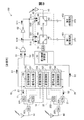
図3は、無線信号の送信時の無線通信装置100の状態を示す説明図である。無線送信部11および無線送信部21から無線信号を送信する場合、無線送信部11において、送信制御部152は、イネーブル信号S1を増幅器101に出力し、増幅器101は、信号出力部151から出力される信号を増幅する。そして増幅後の無線信号が第1アンテナ91から出力される。同時に、無線送信部21において、送信制御部156は、イネーブル信号S2を増幅器201に出力し、増幅器201は、信号出力部155から出力される信号を増幅する。そして、増幅後の無線信号が第1アンテナ92から出力される。
A2. Operation when sending:
FIG. 3 is an explanatory diagram illustrating a state of the
ここで、図3に示すように、送信制御部152から出力されたイネーブル信号S1と、送信制御部156から出力されたイネーブル信号S2とは、同時にOR回路61に入力される。このため、OR回路61からの出力信号S10は、HIとなり、2つのスイッチ回路44、45に入力される。また、出力信号S10を入力するNOT回路62は、LOの出力信号S11を出力する。このため、2つのスイッチ回路44、45には、NOT回路62からLOの出力信号S11が入力される。このため、第2BBプロセッサ160(第2無線受信部30)は、ローノイズアンプ31を介して第2導線42に接続され、さらには、ローノイズアンプ31および第2導線42を介して第1終端抵抗401に接続されることとなる。したがって、無線送信部11および無線送信部21から無線信号を送信する場合、第2無線受信部30は、第2アンテナ93とは電気的に接続されず、第2アンテナ93で受信した電波に基づく無線信号の受信を行わない。このようにして、第1アンテナ91および第1アンテナ92から出力された無線信号を、第2アンテナ93を介して受信することが抑制される。このとき、第2アンテナ93は、第3導線43に接続され、さらには、第3導線43を介して第2終端抵抗402に接続されることとなる。このため、第2アンテナ93で受信した無線信号は第2終端抵抗402によって吸収され、単純に断線させた場合に懸念される「第2アンテナ93から外部への反射波の出力」が抑制される。
Here, as shown in FIG. 3, the enable signal S <b> 1 output from the
A3.受信時の動作:
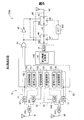
図4は、無線信号の受信時の無線通信装置100の状態を示す説明図である。第1無線受信部12および第1無線受信部22において無線信号を受信する場合、第1無線受信部12において、受信制御部153は、増幅機能を有効化するイネーブル信号(イネーブル信号S3)をローノイズアンプ102に出力し、ローノイズアンプ102は、第1アンテナ91を介して受信する無線信号を増幅して第1BBプロセッサ150に出力する。同時に、第1無線受信部22において受信制御部157は、イネーブル信号S4をローノイズアンプ202に出力し、ローノイズアンプ202は、第1アンテナ92を介して受信する無線信号を増幅して第1BBプロセッサ150に出力する。
A3. Operation when receiving:
FIG. 4 is an explanatory diagram illustrating a state of the
ここで、図4に示すように、送信制御部152および送信制御部156からは、上述のイネーブル信号S1、S2が送信されていない。したがって、OR回路61からの出力信号S20は、LOとなり、2つのスイッチ回路44、45に入力される。また、LOの出力信号S20を入力するNOT回路62は、HIの出力信号S21を出力する。したがって、2つのスイッチ回路44、45には、NOT回路62からHIの出力信号S21が入力される。このため、第2BBプロセッサ160(第2無線受信部30)は、ローノイズアンプ31を介して第1導線41に接続され、第2アンテナ93は第1導線41に接続されることとなる。つまり、第2BBプロセッサ160(第2無線受信部30)と第2アンテナ93とが電気的に接続されることとなる。したがって、第1無線受信部12および第1無線受信部22において無線信号を受信する場合、第2無線受信部30は、第2アンテナ93で受信した電波に基づく無線信号の受信を行う。このとき、無線送信部11および無線送信部21は無線信号を送信していないので、第1アンテナ91および第1アンテナ92から出力された無線信号を、第2アンテナ93を介して受信することは無い。したがって、第2無線受信部30は、第2アンテナ93を介して無線信号を精度良く受信して復調できる。
Here, as shown in FIG. 4, the above-described enable signals S <b> 1 and S <b> 2 are not transmitted from the
以上説明した第1実施形態の無線通信装置100によれば、イネーブル信号S1、S2に基づき生成されるOR回路61の出力信号(HIの信号)が受信無効化部40(第1スイッチ回路44および第2スイッチ回路45)に入力された場合に、第2アンテナ93で受信された電波に基づく無線信号の受信が無効化されるので、無線送信部11、21により無線信号を送信している間に、第2アンテナ93で受信された電波に基づく無線信号の受信を無効化できる。言い換えると、無線送信部11、21により無線信号を送信していない間において第2アンテナ93で受信された電波に基づき無線信号を受信するので、第2アンテナ93による無線信号の受信精度の低下を抑制できる。
According to the
また、受信無効化部40は、OR回路61からの出力信号を入力するので、2つの無線送信部11、21のいずれかの無線通信部において、無線信号が送信されている間に、第2アンテナ93で受信された電波に基づく無線信号の受信を無効化でき、第2アンテナ93による無線信号の受信精度の低下をより確実に抑制できる。また、半二重通信を行う構成において、第2アンテナ93による無線信号の受信精度の低下を抑制できる。
In addition, since the
また、OR回路61に入力されるイネーブル信号S1、S2は、送信制御部152、156が増幅動作を増幅器101、201に指示するための信号と一致するので、イネーブル信号S1、S2とは別に、無線送信部11、12が無線信号を送信していることを示す信号を出力するための専用の構成(信号出力のための専用機能および専用配線)を省略でき、無線通信装置100の製造コストを抑えることができる。
In addition, the enable signals S1 and S2 input to the
また、OR回路61から出力されるHIの出力信号を入力した場合に、第2無線受信部30と第2導線42とが電気的に接続するように第1スイッチ回路44が動作されるので、無線信号が送信されている間に、第2無線受信部30を第1終端抵抗401に電気的に接続でき、無線信号の受信を無効化できる。
In addition, when the HI output signal output from the
また、OR回路61から出力されるHIの出力信号を入力した場合に、第2アンテナ93と第3導線43とが電気的に接続するように第2スイッチ回路45が動作されるので、無線信号が送信されている間に、第2アンテナ93を第2終端抵抗402に電気的に接続できる。このため、第1アンテナ91、92から出力された電波が第2アンテナ93に入力されたとしても、かかる電波が第2無線受信部30に受信されることを抑制できる。加えて、第1アンテナ92から出力された電波が第2アンテナ93に入力されたとしても、かかる入力電波のエネルギーを第2終端抵抗402で吸収でき、単純に断線させた場合に懸念される「第2アンテナ93から外部への反射波の出力」を抑制できる。
In addition, when the HI output signal output from the
また、第2無線受信部30は、無線通信部10、20による無線通信のための周囲の無線通信環境の確認のために第2アンテナ93を用いた無線信号の受信を行うので、かかる無線通信環境を精度良く確認できる。
In addition, since the second
B.第2実施形態:
図5は、第2実施形態の無線通信装置100aの詳細構成を示すブロック図である。第2実施形態の無線通信装置100aは、第2導線42に代えて第2導線47を備える点、および第3導線43に代えて第3導線48を備える点において、図2に示す第1実施形態の無線通信装置100と異なる。第2実施形態の無線通信装置100aにおけるその他の構成は、第1実施形態の無線通信装置100と同じであるので、同一の構成要素には同一の符号を付し、その詳細な説明を省略する。
B. Second embodiment:
FIG. 5 is a block diagram illustrating a detailed configuration of the
図5に示すように、第2導線47および第3導線48は、いずれもアッテネータ300に電気的に接続されている。そして、第2導線47、アッテネータ300、第3導線48の順序で並んだ導電経路が構成されている。アッテネータ300は、入力信号を減衰させる。具体的には、本実施形態では、アッテネータ300は、第2アンテナ93により受信した電波を復調不可能な程度まで減衰する。なお、減衰の程度は、復調不可能な程度に限らず、受信精度の低下を抑制できる任意の程度であってもよい。
As shown in FIG. 5, the
第1無線受信部12および第1無線受信部22において無線信号を受信する場合、第1実施形態の図4に示すように、第1スイッチ回路44には、OR回路61からのLOの出力信号S20と、NOT回路62からのHIの出力信号S21とが入力される。このため、図5に示すように、第1スイッチ回路44は、第2BBプロセッサ160(第2無線受信部30)と第1導線41とを接続する。同時に、第2スイッチ回路45は、第2アンテナ93と第1導線41とを接続する。したがって、第1実施形態と同様に、第2無線受信部30は、第2アンテナ93で受信した電波に基づく無線信号の受信を行う。
When the first
これに対して、無線送信部11および無線送信部21から無線信号を送信する場合、第1実施形態の図3に示すように、第1スイッチ回路44には、OR回路61からのHIの出力信号S10と、NOT回路62からのLOの出力信号S11とが入力される。このため、第1スイッチ回路44は、第2BBプロセッサ160(第2無線受信部30)と第2導線47とを接続する。また、第2スイッチ回路45は、第2アンテナ93と第3導線48とを接続する。したがって、第2アンテナ93と第2BBプロセッサ160(第2無線受信部30)とは、アッテネータ300を介して電気的に接続される。しかし、第2アンテナ93で受信された無線信号は、アッテネータ300において減衰されて第2無線受信部30に入力されるため、アッテネータ300が無く減衰されずに受信する場合に比べて、周囲の無線通信環境の確認に対する影響は小さい。このため、第2実施形態の無線通信装置100aにおいても、第2無線受信部30は、第2アンテナ93を介して無線信号を精度良く受信して復調できる。
On the other hand, when a radio signal is transmitted from the
以上説明した第2実施形態の無線通信装置100aは、第1実施形態の無線通信装置100と同様な効果を有する。なお、第1実施形態および第2実施形態から理解できるように、第2アンテナ93において受信した電波を第2無線受信部30において受信しない、或いは、第2アンテナ93において受信した電波を減衰させて第2無線受信部30に受信させることは、課題を解決するための手段欄における「第2アンテナで受信された電波に基づく無線信号の受信を、無効化する」の下位概念に相当する。
The
C.第3実施形態:
図6は、第3実施形態の無線通信装置100bの詳細構成を示すブロック図である。第3実施形態の無線通信装置100bは、ローノイズアンプ31に代えてローノイズアンプ49を備える点において、第2実施形態の無線通信装置100aと異なる。第3実施形態の無線通信装置100bにおけるその他の構成は、第2実施形態の無線通信装置100bと同じであるので、同一の構成要素には同一の符号を付し、その詳細な説明を省略する。
C. Third embodiment:
FIG. 6 is a block diagram illustrating a detailed configuration of the
このような構成を有する第3実施形態の無線通信装置100bは、第2実施形態の無線通信装置100aと同様な効果を有する。
The
D.第4実施形態:
図7は、第3実施形態の無線通信装置100cの詳細構成を示すブロック図である。第4実施形態の無線通信装置100cは、受信無効化部40に代えて受信無効化部40aを備える点と、2つの終端抵抗401、402が省略されている点とにおいて、図2に示す第1実施形態の無線通信装置100と異なる。第4実施形態の無線通信装置100cにおけるその他の構成は、第1実施形態の無線通信装置100と同じであるので、同一の構成要素には同一の符号を付し、その詳細な説明を省略する。
D. Fourth embodiment:
FIG. 7 is a block diagram illustrating a detailed configuration of the
第4実施形態の受信無効化部40aは、ローノイズアンプ31のみで構成されている。NOT回路62から出力される出力信号S11、S21は、いずれも、イネーブル信号として、ローノイズアンプ31に入力される。
The
図3を用いて説明したように、無線信号の送信時には、OR回路61からの出力信号S10がNOT回路62に入力されるため、NOT回路62は、LOの出力信号S11をローノイズアンプ31に出力する。したがって、この場合、ローノイズアンプ31は増幅を行わないため、第2アンテナ93で受信された信号は、第2無線受信部30において有効な信号として受信されない。
As described with reference to FIG. 3, since the output signal S10 from the
これに対して、図4を用いて説明したように、無線信号の受信時には、OR回路61からの出力信号S20がNOT回路62に入力されるため、NOT回路62は、HIの出力信号S21をローノイズアンプ31に出力する。したがって、この場合、ローノイズアンプ31は増幅を実行し、第2アンテナ93で受信された信号は、第2無線受信部30において有効な信号として受信されることとなる。
On the other hand, as described with reference to FIG. 4, the output signal S20 from the
以上の構成を有する第4実施形態の無線通信装置100cは、第1実施形態の無線通信装置100と同様な効果を有する。加えて、受信無効化部40aを簡易な構成で実現できるため、無線通信装置100cの製造コストを抑えることができる。
The
E.変形例:
E1.変形例1:
各実施形態の無線通信装置100、100aは、2つの無線通信部10、20を備えていたが、1つの無線通信装置、または、3つ以上の任意の数の無線通信部を備えてもよい。1つの無線通信装置を備える構成においては、OR回路61を省略して、各スイッチ回路44、45にイネーブル信号を入力してもよい。
E. Variation:
E1. Modification 1:
The
E2.変形例2:
各実施形態では、OR回路61に入力される信号は、イネーブル信号S1、S2であったが、これらの信号に代えて、または、これらの信号に加えて、無線送信部11、21による無線通信の送信が行われていることを示す任意の信号を、OR回路61に入力してもよい。
E2. Modification 2:
In each embodiment, the signals input to the
E3.変形例3:
第1スイッチ回路44および第2スイッチ回路45の詳細構成は、各実施形態の構成に限らない。例えば、第1実施形態においては、無線送信部11および無線送信部21から無線信号を送信する場合に第2アンテナ93と第2BBプロセッサ160(第2無線受信部30)とを電気的に絶縁し、第1無線受信部12および第1無線受信部22において無線信号を受信する場合に第2アンテナ93と第2BBプロセッサ160(第2無線受信部30)とを電気的に接続可能な任意の構成を採用してもよい。また、第2実施形態においては、無線送信部11および無線送信部21から無線信号を送信する場合に第2アンテナ93と第2BBプロセッサ160(第2無線受信部30)とをアッテネータ300を介して電気的に接続し、第1無線受信部12および第1無線受信部22において無線信号を受信する場合に第2アンテナ93と第2BBプロセッサ160(第2無線受信部30)とをアッテネータ300を介さずに電気的に接続可能な任意の構成を採用してもよい。
E3. Modification 3:
The detailed configuration of the
E4.変形例4:
第1実施形態において、第3導線43および第2スイッチ回路45を省略してもよい。つまり、第2アンテナ93と第1導線41とを常時電気的に接続する構成としてもよい。この構成においても、無線送信部11および無線送信部21から無線信号を送信する場合に、第1スイッチ回路44によって、第2BBプロセッサ160(第2無線受信部30)を第2導線42を介して第1終端抵抗401に接続させ、また、第1無線受信部12および第1無線受信部22において無線信号を受信する場合に、第1スイッチ回路44によって、第2BBプロセッサ160(第2無線受信部30)を第1導線41を介して第2アンテナ93に接続させることができ、第1実施形態の無線通信装置100と同様な効果を奏する。
E4. Modification 4:
In the first embodiment, the
E5.変形例5:
各実施形態では、第2無線受信部30は、無線通信装置100、100aの周囲の無線通信環境の確認のために第2アンテナ93を用いた無線信号の受信を行っていたが、本発明はこれに限定されない。例えば、MIMOにおける通信相手との通信モードのネゴシエーションの結果、無線通信装置100、100aが2×2であって相手が3×3の場合、無線通信装置100、100aにおける通信モードを2×3に変更して復調をサポートするために、第2アンテナ93を用いた無線信号の受信を行ってもよい。このような構成であっても、例えば、第1実施形態のように、無線送信部11、21が無線信号の出力を行っていない場合に、第2アンテナ93を介した無線信号の受信を行うことにより、第1実施形態の無線通信装置100と同様な効果を奏する。また、例えば、第2実施形態と同様な動作とすることにより、第2実施形態の無線通信装置100aと同様な効果を奏する。
E5. Modification 5:
In each embodiment, the second
E6.変形例6:
各実施形態では、2つの無線通信部10、20は、いずれもIEEE802.11nに規定された2.4GHz帯の周波数帯域を用いた無線通信を行っていたが、2.4GHz帯に代えて、他の任意の周波数帯、例えば、5GHz帯の周波数帯域を用いた無線通信を行ってもよい。また、複数の周波数帯域を用いた無線通信を行ってもよい。例えば、無線送信部11が2.4GHz帯の周波数帯域を用い、無線送信部21が5GHz帯の周波数帯域を用いてもよい。このように複数の周波数帯を用いた無線通信を行う場合、第2無線受信部30を、各周波数帯域に対して1つずつ設ける必要がある。例えば、上述のように、無線送信部11が2.4GHz帯の周波数帯域を用い、無線送信部21が5GHz帯の周波数帯域を用いる場合には、2.4GHz帯の周波数帯域用の第2無線受信部30と、5GHz帯の周波数帯域用の第2無線受信部30の合計2つの第2無線受信部30を設ける必要がある。
E6. Modification 6:
In each embodiment, the two
E7.変形例7:
各実施形態では、無線通信装置100、100aは、無線LANアクセスポイント装置として機能していたが、本発明はこれに限定されない。例えば、パーソナルコンピュータや、スマートフォンや、携帯電話端末といった、無線通信を行う任意の装置として機能してもよい。
E7. Modification 7:
In each embodiment, the
E8.変形例8:
第1実施形態では、第1終端抵抗401および第2終端抵抗402は、いずれも無線通信装置100が備えていたが、無線通信装置100が備えていない構成としてもよい。この場合であっても、第2導線42および第3導線43を、無線通信装置100とは別に用意された終端抵抗にそれぞれ接続することにより、第1実施形態と同様な効果を奏することができる。
E8. Modification 8:
In the first embodiment, the
E9.変形例9:
各実施形態において、ハードウェアによって実現されていた構成の一部をソフトウェアに置き換えるようにしてもよく、逆に、ソフトウェアによって実現されていた構成の一部をハードウェアに置き換えるようにしてもよい。また、本発明の機能の一部または全部がソフトウェアで実現される場合には、そのソフトウェア(コンピュータプログラム)は、コンピュータ読み取り可能な記録印刷媒体に格納された形で提供することができる。「ハードウェア」としては、例えば、集積回路、ディスクリート回路、または、それらの回路を組み合わせたモジュールを利用可能である。「コンピュータ読み取り可能な記録印刷媒体」とは、フレキシブルディスクやCD−ROMのような携帯型の記録印刷媒体に限らず、各種のRAMやROM等のコンピュータ内の内部記憶装置や、ハードディスク等のコンピュータに固定されている外部記憶装置も含んでいる。すなわち、「コンピュータ読み取り可能な記録印刷媒体」とは、データを一時的ではなく固定可能な任意の記録印刷媒体を含む広い意味を有している。
E9. Modification 9:
In each embodiment, a part of the configuration realized by hardware may be replaced by software, and conversely, a part of the configuration realized by software may be replaced by hardware. When a part or all of the functions of the present invention are realized by software, the software (computer program) can be provided in a form stored in a computer-readable recording print medium. As the “hardware”, for example, an integrated circuit, a discrete circuit, or a module combining these circuits can be used. The “computer-readable recording / printing medium” is not limited to a portable recording / printing medium such as a flexible disk or a CD-ROM, but an internal storage device in a computer such as various RAMs and ROMs, or a computer such as a hard disk. It also includes an external storage device fixed to the storage. That is, the “computer-readable recording / printing medium” has a broad meaning including an arbitrary recording / printing medium capable of fixing data, not temporarily.
本発明は、上述の実施形態や変形例に限られるものではなく、その趣旨を逸脱しない範囲において種々の構成で実現することができる。例えば、発明の概要の欄に記載した各形態中の技術的特徴に対応する実施形態、変形例中の技術的特徴は、上述の課題の一部又は全部を解決するために、あるいは、上述の効果の一部又は全部を達成するために、適宜、差し替えや、組み合わせを行うことが可能である。また、その技術的特徴が本明細書中に必須なものとして説明されていなければ、適宜、削除することが可能である。 The present invention is not limited to the above-described embodiments and modifications, and can be realized with various configurations without departing from the spirit thereof. For example, the technical features in the embodiments and the modifications corresponding to the technical features in each embodiment described in the summary section of the invention are to solve some or all of the above-described problems, or In order to achieve part or all of the effects, replacement or combination can be performed as appropriate. Further, if the technical feature is not described as essential in the present specification, it can be deleted as appropriate.
10…無線通信部
11…無線送信部
12…第1無線受信部
20…無線通信部
21…無線送信部
22…第1無線受信部
30…第2無線受信部
31…ローノイズアンプ
40…受信無効化部
41…第1導線
42…第2導線
43…第3導線
44…第1スイッチ回路
45…第2スイッチ回路
47…第2導線
48…第3導線
50…アプリケーションプロセッサ
61…OR回路
62…NOT回路
91…第1アンテナ
92…第1アンテナ
93…第2アンテナ
100…無線通信装置
100a…無線通信装置
100b…無線通信装置
100c…無線通信装置
101…増幅器
102…ローノイズアンプ
103…送受信切替スイッチ
150…第1ベースバンドプロセッサ(第1BBプロセッサ)
151…信号出力部
152…送信制御部
153…受信制御部
155…信号出力部
156…送信制御部
157…受信制御部
160…第2ベースバンドプロセッサ(第2BBプロセッサ)
201…増幅器
202…ローノイズアンプ
203…送受信切替スイッチ
300…アッテネータ
401…第1終端抵抗
402…第2終端抵抗
S1…イネーブル信号
S10…出力信号
S11…出力信号
S2…イネーブル信号
S20…出力信号
S21…出力信号
S3…イネーブル信号
S4…イネーブル信号
DESCRIPTION OF
DESCRIPTION OF
DESCRIPTION OF
Claims (7)
無線送信部と第1無線受信部とを有する1つ以上の無線通信部であって、前記無線送信部による無線信号の送信が行われている場合に、該送信が行われていることを示す送信実行信号を出力する無線通信部と、
前記無線通信部による無線通信のために電波の送受信を行う1つ以上の第1アンテナと、
無線信号の送信と無線信号の受信とのうち、無線信号の受信を行う第2無線受信部と、
前記第2無線受信部による無線信号の受信のために、電波の送信と電波の受信とのうち、電波の受信を行う第2アンテナと、
前記送信実行信号又は前記送信実行信号に基づき生成される無効化実行信号を入力した場合に、前記第2アンテナで受信された電波に基づく無線信号の受信を、無効化する受信無効化部と、
を備える、
無線通信装置。 A wireless communication device,
One or more wireless communication units having a wireless transmission unit and a first wireless reception unit, and when the wireless transmission unit transmits a wireless signal, indicates that the transmission is performed A wireless communication unit that outputs a transmission execution signal;
One or more first antennas for transmitting and receiving radio waves for wireless communication by the wireless communication unit;
Of the transmission of the radio signal and the reception of the radio signal, a second radio reception unit that receives the radio signal;
A second antenna for receiving radio waves among radio wave transmission and radio wave reception for receiving radio signals by the second radio reception unit;
A reception invalidation unit for invalidating reception of a radio signal based on the radio wave received by the second antenna when the transmission execution signal or the invalidation execution signal generated based on the transmission execution signal is input;
Comprising
Wireless communication device.
複数の前記無線通信部と、
複数の前記無線通信部がそれぞれ出力する前記送信実行信号を入力し、前記無効化実行信号を出力するOR回路と、
を更に備え、
前記受信無効化部は、前記OR回路から出力される前記無効化実行信号を入力する、
無線通信装置。 The wireless communication device according to claim 1,
A plurality of the wireless communication units;
An OR circuit that inputs the transmission execution signal output by each of the plurality of wireless communication units and outputs the invalidation execution signal;
Further comprising
The reception invalidation unit inputs the invalidation execution signal output from the OR circuit.
Wireless communication device.
前記無線通信部は、半二重通信により、無線通信を実行する、
無線通信装置。 The wireless communication apparatus according to claim 1 or 2,
The wireless communication unit performs wireless communication by half-duplex communication.
Wireless communication device.
前記無線送信部は、信号出力部と、前記信号出力部からの出力信号を増幅する増幅器と、前記増幅器による増幅動作を指示する送信制御部と、を有し、
前記送信実行信号は、前記送信制御部が前記増幅動作を前記増幅器に指示するための信号と一致する、
無線通信装置。 The wireless communication device according to claim 3.
The wireless transmission unit includes a signal output unit, an amplifier that amplifies an output signal from the signal output unit, and a transmission control unit that instructs an amplification operation by the amplifier,
The transmission execution signal coincides with a signal for the transmission control unit to instruct the amplifier to perform the amplification operation.
Wireless communication device.
前記受信無効化部は、
前記第2無線受信部を前記第2アンテナに電気的に接続するための第1導線と、
前記第2無線受信部を第1終端抵抗に電気的に接続するための第2導線と、
前記第2無線受信部を、前記第1導線と前記第2導線とのうちのいずれかに選択的に接続するための第1スイッチ回路と、
を有し、前記無効化実行信号を入力した場合に、前記第2無線受信部と前記第2導線とが電気的に接続するように前記第1スイッチ回路を動作させる、
無線通信装置。 In the radio | wireless communication apparatus as described in any one of Claim 1- Claim 4,
The reception invalidation unit
A first conductor for electrically connecting the second wireless receiver to the second antenna;
A second conductor for electrically connecting the second wireless receiver to a first termination resistor;
A first switch circuit for selectively connecting the second wireless receiver to either the first conductor or the second conductor;
And when the invalidation execution signal is input, operate the first switch circuit so that the second wireless reception unit and the second conductor are electrically connected.
Wireless communication device.
前記受信無効化部は、
前記第2アンテナを第2終端抵抗に電気的に接続するための第3導線と、
前記第2アンテナを、前記第1導線と前記第3導線とのうちのいずれかに選択的に接続するための第2スイッチ回路と、
を有し、前記無効化実行信号を入力した場合に、前記第2アンテナと前記第3導線とが電気的に接続するように前記第2スイッチ回路を動作させる、
無線通信装置。 The wireless communication device according to claim 5, wherein
The reception invalidation unit
A third conductor for electrically connecting the second antenna to a second termination resistor;
A second switch circuit for selectively connecting the second antenna to either the first conductor or the third conductor;
And when the invalidation execution signal is input, operate the second switch circuit so that the second antenna and the third conductor are electrically connected.
Wireless communication device.
前記第2無線受信部は、前記無線通信部による無線通信のための周囲の無線通信環境の確認のために前記第2アンテナを用いた無線信号の受信を行う、
無線通信装置。 In the radio | wireless communication apparatus as described in any one of Claim 1- Claim 6,
The second radio reception unit receives a radio signal using the second antenna for confirmation of a surrounding radio communication environment for radio communication by the radio communication unit;
Wireless communication device.
Priority Applications (1)
| Application Number | Priority Date | Filing Date | Title |
|---|---|---|---|
| JP2017094593A JP6901679B2 (en) | 2017-05-11 | 2017-05-11 | Wireless communication device |
Applications Claiming Priority (1)
| Application Number | Priority Date | Filing Date | Title |
|---|---|---|---|
| JP2017094593A JP6901679B2 (en) | 2017-05-11 | 2017-05-11 | Wireless communication device |
Publications (2)
| Publication Number | Publication Date |
|---|---|
| JP2018191237A true JP2018191237A (en) | 2018-11-29 |
| JP6901679B2 JP6901679B2 (en) | 2021-07-14 |
Family
ID=64479136
Family Applications (1)
| Application Number | Title | Priority Date | Filing Date |
|---|---|---|---|
| JP2017094593A Active JP6901679B2 (en) | 2017-05-11 | 2017-05-11 | Wireless communication device |
Country Status (1)
| Country | Link |
|---|---|
| JP (1) | JP6901679B2 (en) |
Citations (4)
| Publication number | Priority date | Publication date | Assignee | Title |
|---|---|---|---|---|
| JPH07123077A (en) * | 1993-10-20 | 1995-05-12 | Sanyo Electric Co Ltd | Space diversity transmitter-receiver |
| JP2004266737A (en) * | 2003-03-04 | 2004-09-24 | Matsushita Electric Ind Co Ltd | Transmission / reception device and transmission / reception method |
| JP4300214B2 (en) * | 2003-03-10 | 2009-07-22 | 株式会社バッファロー | access point |
| JP2012109833A (en) * | 2010-11-18 | 2012-06-07 | Nec Access Technica Ltd | Wireless lan access point device, control method for wireless lan access point device and control program therefor |
-
2017
- 2017-05-11 JP JP2017094593A patent/JP6901679B2/en active Active
Patent Citations (4)
| Publication number | Priority date | Publication date | Assignee | Title |
|---|---|---|---|---|
| JPH07123077A (en) * | 1993-10-20 | 1995-05-12 | Sanyo Electric Co Ltd | Space diversity transmitter-receiver |
| JP2004266737A (en) * | 2003-03-04 | 2004-09-24 | Matsushita Electric Ind Co Ltd | Transmission / reception device and transmission / reception method |
| JP4300214B2 (en) * | 2003-03-10 | 2009-07-22 | 株式会社バッファロー | access point |
| JP2012109833A (en) * | 2010-11-18 | 2012-06-07 | Nec Access Technica Ltd | Wireless lan access point device, control method for wireless lan access point device and control program therefor |
Also Published As
| Publication number | Publication date |
|---|---|
| JP6901679B2 (en) | 2021-07-14 |
Similar Documents
| Publication | Publication Date | Title |
|---|---|---|
| CN108988877B (en) | Radio frequency system, antenna switching control method and related products | |
| CN114665940B (en) | Radio frequency system, antenna switching control method, related equipment and storage medium | |
| US8706061B2 (en) | Method for simultaneous transmitter operation | |
| JP5657547B2 (en) | transceiver | |
| US12562758B2 (en) | Bluetooth chip, signal receiving method, and bluetooth communications apparatus | |
| CN106685468A (en) | Radio frequency circuit, terminal and radio frequency circuit control method | |
| CN108833701B (en) | Antenna control method, antenna system and terminal | |
| WO2022135233A1 (en) | Antenna circuit and electronic device | |
| CN113472385A (en) | Radio frequency circuit, antenna device and electronic equipment | |
| JP5388307B2 (en) | Portable wireless device | |
| CN201601211U (en) | Apparatus and system for use in portable applications | |
| CN113708793A (en) | Wireless communication circuit, electronic device, and wireless communication method | |
| CN107750433B (en) | Method and apparatus for signaling with transmit activity probes | |
| KR20120027738A (en) | Wireless data-communication module having internal and external antenna | |
| US20100061279A1 (en) | Transmitting and Receiving Wireless Signals Via Dual Antennas | |
| JP5615324B2 (en) | Mobile communication terminal | |
| JP6901679B2 (en) | Wireless communication device | |
| CN117220711A (en) | RF architecture and electronic equipment | |
| CN108768420B (en) | Antenna processing method, system and antenna assembly | |
| WO2016185871A1 (en) | Wireless communication device | |
| CN213484847U (en) | Electronic equipment | |
| CN111800158B (en) | Electronic equipment | |
| CN215300623U (en) | Wireless transmission circuit and radio frequency equipment | |
| CN117200815A (en) | Signal transmitting methods, devices and electronic equipment | |
| CN114499549A (en) | Ultra-wideband communication system and electronic equipment |
Legal Events
| Date | Code | Title | Description |
|---|---|---|---|
| A621 | Written request for application examination |
Free format text: JAPANESE INTERMEDIATE CODE: A621 Effective date: 20200121 |
|
| A977 | Report on retrieval |
Free format text: JAPANESE INTERMEDIATE CODE: A971007 Effective date: 20201009 |
|
| A131 | Notification of reasons for refusal |
Free format text: JAPANESE INTERMEDIATE CODE: A131 Effective date: 20201027 |
|
| A521 | Request for written amendment filed |
Free format text: JAPANESE INTERMEDIATE CODE: A523 Effective date: 20201221 |
|
| TRDD | Decision of grant or rejection written | ||
| A01 | Written decision to grant a patent or to grant a registration (utility model) |
Free format text: JAPANESE INTERMEDIATE CODE: A01 Effective date: 20210518 |
|
| A61 | First payment of annual fees (during grant procedure) |
Free format text: JAPANESE INTERMEDIATE CODE: A61 Effective date: 20210531 |
|
| R150 | Certificate of patent or registration of utility model |
Ref document number: 6901679 Country of ref document: JP Free format text: JAPANESE INTERMEDIATE CODE: R150 |
|
| R250 | Receipt of annual fees |
Free format text: JAPANESE INTERMEDIATE CODE: R250 |
|
| R250 | Receipt of annual fees |
Free format text: JAPANESE INTERMEDIATE CODE: R250 |
|
| S111 | Request for change of ownership or part of ownership |
Free format text: JAPANESE INTERMEDIATE CODE: R313111 |
|
| R350 | Written notification of registration of transfer |
Free format text: JAPANESE INTERMEDIATE CODE: R350 |