JP2018181237A - Construction assistance system - Google Patents
Construction assistance system Download PDFInfo
- Publication number
- JP2018181237A JP2018181237A JP2017084347A JP2017084347A JP2018181237A JP 2018181237 A JP2018181237 A JP 2018181237A JP 2017084347 A JP2017084347 A JP 2017084347A JP 2017084347 A JP2017084347 A JP 2017084347A JP 2018181237 A JP2018181237 A JP 2018181237A
- Authority
- JP
- Japan
- Prior art keywords
- line
- unit
- image
- construction
- data
- Prior art date
- Legal status (The legal status is an assumption and is not a legal conclusion. Google has not performed a legal analysis and makes no representation as to the accuracy of the status listed.)
- Granted
Links
Images
Landscapes
- Position Input By Displaying (AREA)
- User Interface Of Digital Computer (AREA)
Abstract
【課題】ライン引きを行う作業者を効率的にアシストすることができる設営アシストシステムを提供する。【解決手段】会場の実測データ5に基準ポール及びラインの位置がレイアウトされた設営データ7を記憶する端末記憶部34と、視界撮像部31によって撮像された視界画像内の基準ポールの大きさ及び位置に基づいて、メガネ型端末3の現在位置情報を特定する現在位置特定部362と、視界画像を解析することで会場に引かれている設営済みラインを特定する設営検証部363と、現在位置情報及び設営データ7に基づいて、ラインの設営位置を案内する案内ラインをAR画像として描画してAR画像表示部32に表示させる設営画像描画部365とを備え、設営画像描画部365は、設営済みライン上の案内ラインと、ラインが引かれていない箇所の案内ラインとを区別して描画する。【選択図】図3A setup assist system capable of efficiently assisting a worker who performs line drawing is provided. A terminal storage unit 34 for storing setting data 7 in which the positions of the reference pole and the line are laid out in the actual measurement data 5 of the venue, the size of the reference pole in the view image captured by the view image pickup unit 31, and A current position specifying unit 362 for specifying current position information of the glasses-type terminal 3 based on the position; a setting verification unit 363 for specifying a set line drawn in the hall by analyzing a view field image; and a current position A setting image drawing unit 365 that draws a guide line for guiding the setting position of the line based on the information and the setting data 7 as an AR image and displays it on the AR image display unit 32. The setting image drawing unit 365 includes The guide line on the completed line is drawn separately from the guide line where the line is not drawn. [Selection] Figure 3
Description
本発明は、会場の設営をアシストする設営アシストシステムに関する。 The present invention relates to a construction assistance system that assists in setting up a venue.
野外でスポーツやイベントを行う際の会場の設営は労力の掛る作業であり、作業の軽減化や効率化のための技術が求められている。そこで、従来技術として、ライン引きを行う自走式のラインカーが提案されている(例えば、特許文献1、2参照)。
Setting up a venue for outdoor sports and events is a labor-intensive task, and technology is required to reduce the work and improve efficiency. Then, the self-propelled line car which performs line drawing as a prior art is proposed (for example, refer to
しかしながら、従来技術では、会場の設営を行う作業者は、自動で行われるライン引きを見守ることしかできず、作業者が行う作業について効率的にアシストすることができないという問題点があった。 However, in the prior art, the worker who sets up the hall can only watch the line drawing performed automatically, and can not efficiently assist the worker's work.
本発明は、かかる点に鑑みてなされたものであり、その目的とするところは、ライン引きを行う作業者を効率的にアシストすることができる設営アシストシステムを提供することにある。 This invention is made in view of this point, The place made into the objective is to provide the construction assistance system which can assist the worker who performs line drawing efficiently.
本発明の画像形成装置の管理システムは、会場にラインを設営する作業者を、前記作業者の前方視界を撮像する視界撮像部と、前記作業者の前方視界に重畳されて表示される画像表示部とを備えたメガネ型端末を用いてアシストする設営アシストシステムであって、既知長の基体部を有し、前記会場の複数の既知点にそれぞれ設置された複数の基準ポールと、前記会場の実測データに前記基準ポール及び前記ラインの位置がレイアウトされた設営データを記憶する設営データ記憶部と、前記視界撮像部によって撮像された視界画像内の前記基準ポールを検出する基準ポール検出部と、前記基準ポール検出部によって複数の前記基準ポールが検出されると、視界画像内の前記基準ポールの大きさ及び位置に基づいて、前記実測データ内における前記メガネ型端末の現在位置及び姿勢を現在位置情報として特定する現在位置特定部と、前記視界画像を解析することで前記会場に引かれている設営済みラインを特定する設営検証部と、前記現在位置情報及び前記設営データに基づいて、前記ラインの設営位置を案内する案内ラインを拡張現実画像として描画して前記画像表示部に表示させる設営画像描画部と、を具備し、前記設営画像描画部は、前記設営済みライン上の前記案内ラインと、前記ラインが引かれていない箇所の前記案内ラインとを区別して描画することを特微とする。
さらに、本発明の設営アシストシステムにおいて、前記設営検証部は、前記設営済みラインと、前記設営データとを比較し、正しく前記設営済みラインが引かれているか否かを判断し、前記設営画像描画部は、正しく引かれていない前記設営済みライン上の前記案内ラインを他の箇所と区別して描画しても良い。
さらに、本発明の設営アシストシステムにおいて、前記ラインの設営を担当する作業者が前記ラインを分割したラインパーツ毎に設定された計画データを記憶する計画データ記憶部と、前記作業者の選択を受け付ける操作部と、を具備し、前記設営画像描画部は、前記案内ラインにおいて、選択された作業者が設営を担当するラインパーツを他の作業者の担当分と区別して描画しても良い。
さらに、本発明の設営アシストシステムにおいて、前記設営済みラインのライン長を前記ラインパーツ毎に算出し、前記作業者毎の進捗率を算出する進捗管理部を具備し、前記設営画像描画部は、選択された作業者の進捗率を通知する進捗画面を生成して前記拡張現実画像内に配置させても良い。
The management system of the image forming apparatus according to the present invention includes an operator displaying the line in the hall, an image capturing unit for imaging a front view of the worker, and an image display displayed superimposed on the front view of the worker And a plurality of reference poles each having a base portion of known length and installed respectively at a plurality of known points of the hall, and A construction data storage unit that stores, in actual measurement data, construction data in which the positions of the reference pole and the line are laid out; a reference pole detection unit that detects the reference pole in a view image captured by the view imaging unit; When a plurality of reference poles are detected by the reference pole detection unit, based on the size and the position of the reference poles in the view image, within the actual measurement data A current position specifying unit which specifies the current position and posture of the eyeglass-type terminal as current position information; a construction verification unit which specifies a constructed line drawn to the hall by analyzing the visibility image; An installation image drawing unit which draws a guide line for guiding the installation position of the line as an augmented reality image based on the position information and the installation data, and displays the same on the image display unit, the installation image drawing unit The feature is to distinguish and draw the guide line on the established line and the guide line at a place where the line is not drawn.
Furthermore, in the construction assistance system of the present invention, the construction verification unit compares the construction line with the construction data to determine whether the construction line is correctly drawn or not, and the construction image drawing is performed. The part may draw the guide line on the setup line that is not drawn correctly, separately from other parts.
Further, in the construction assisting system of the present invention, a worker in charge of setting the line stores a plan data storage unit storing plan data set for each line part obtained by dividing the line, and the selection of the worker The setting image drawing unit may draw a line part, which the selected operator takes charge of setting, in the guide line so as to distinguish it from other workers.
Furthermore, in the construction assisting system of the present invention, the construction image drawing unit further comprises a progress management unit that calculates the line length of the already constructed line for each of the line parts and calculates the progress rate for each worker. A progress screen for notifying the progress rate of the selected worker may be generated and arranged in the augmented reality image.
本発明によれば、作業者の視界に会場に設営すべきラインの拡張現実画像を重畳させて表示することができるため、作業者は拡張現実画像を見ながらライン引きを行うことができ、会場の設営を行う作業者を効率的にアシストすることができるという効果を奏する。 According to the present invention, since the augmented reality image of the line to be set up in the venue can be superimposed and displayed on the field of view of the worker, the worker can draw a line while viewing the augmented reality image. The effect of being able to assist the worker who sets up efficiently is produced.
次に、本発明の実施の形態を、図面を参照して具体的に説明する。 Next, embodiments of the present invention will be specifically described with reference to the drawings.
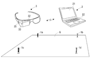
本実施の形態の設営アシストシステムは、スポーツやイベントを行う際の会場の設営をアシストするシステムであり、図1を参照すると、会場Gに設置する基準ポール1a〜1dと、設営プラン管理装置2と、メガネ型端末3と、を備えている。
The construction assistance system of the present embodiment is a system for assisting the construction of a hall when performing sports and events. Referring to FIG. 1,
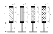
基準ポール1a〜1dは、図2に示すように、円柱状の基体部11と、中心軸が垂直になるように基体部11を支持する足部12とを備えている。基体部11には、基体部11の基体長(長さ)を明確にするための計測基準部13と、基準ポール1a〜1dを区別して識別するための識別部14とが形成されている。本実施の形態において、計測基準部13は、基体部11の両端にそれぞれ表記された帯状のマーク(印)で構成し、識別部14は、計測基準部13に挟まれた領域に表記された、基準ポール1a〜1dで異なるパターン(模様)で構成した。なお、識別部14として、基準ポール1a〜1dで異なる色を用いるようにしても良い。この場合、基準ポール1a〜1d自体の色や計測基準部13の色によって、基準ポール1a〜1dを区別して識別することができる。
The reference |
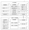
設営プラン管理装置2は、プログラム制御で動作するパーソナルコンピューターである。設営プラン管理装置2は、図3を参照すると、液晶ディスプレイ等の本体表示部21と、キーボード、マウス、タッチパネル等の本体入力部22と、半導体メモリ等の本体記憶部23と、本体通信部24と、本体制御部25と、を備えている。
The construction
本体記憶部23には、基準データ4、実測データ5及びラインデータ6が記憶されていると共に、設営プラン管理装置2によって生成された設営データ7及び計画データ8が記憶される。
The main
基準データ4は、基準ポール1a〜1dを識別し、基準ポール1a〜1dとの距離を認識するためのデータである。基準データ4は、識別部14と照合する照合データと、基体部11の基体長Xと、足部12の足長Yとを有し、照合データ、基体長X及び足長Yが、基準ポール1a〜1d毎に設定されている。なお、本実施の形態では、全ての基準ポール1a〜1dにおいて、基体長X及び足長Yを同一の設定としたが、基準ポール1a〜1d毎に、基体長X及び足長Yを変えても良い。
The
実測データ5は、設営を行う会場の地形データと、磁針方位情報とからなる。
The
ラインデータ6は、サッカー場、Nメートルトラック(直線、楕円状)、野球場、ラグビー場、テニスコート等のライン(白線)の形状及び寸法(ライン長、ライン幅)からなる。なお、各ラインの寸法は、各競技の規則に基づいて許容範囲が設定されている。
The
本体制御部25は、本体表示部21、本体入力部22、本体記憶部23及び本体通信部24にそれぞれ接続され、設営プラン管理装置2全体の動作制御を実行する。本体制御部25は、CPU(Central Processing Unit)、ROM(Read Only Memory)、RAM(Random Access Memory)等を備えたマイクロコンピュータ等の情報処理部である。ROMには設営プラン管理装置2の動作制御を行うための制御プログラムが記憶されている。本体制御部25のCPUは、ROMに記憶されている制御プログラムを読み出し、制御プログラムをRAMに展開させることで、装置全体の制御を行う。また、本体制御部25は、設営データ生成部251及び計画データ生成部252としてそれぞれ機能する。
The main
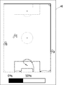
設営データ生成部251は、図4に示すように、会場Gの実測データ5に、基準ポール1a〜1dと、ラインとの位置がレイアウトされた設営データ7を生成する。設営データ生成部251は、本体表示部21に会場設営プラン作成画面として会場Gの実測データ5を表示させ、基準ポール1a〜1dと、ラインとの配置を受け付ける。なお、図4に示す設営データ7では、会場Gの実測データ5に、基準ポール1a〜1dが配置されていると共に、サッカー場のラインが配置されている。
As shown in FIG. 4, the construction
設営データ生成部251は、本体入力部22からの操作によって、図形の種類や寸法(ライン長、ライン幅)を指定したラインの入力及び配置や、ラインデータ6の選択及び配置を受け付け、ラインを2次元データとして会場Gに配置させる。なお、設営データ生成部251は、ラインデータ6の選択を受け付けた場合、設定されている許容範囲内でサイズの変更を受け付ける。これにより、各競技のラインを会場Gの形に合わせて調整することができる。
The construction
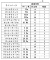
また、設営データ生成部251は、会場Gに配置させるラインを、複数のラインパーツに分割して生成する。ラインパーツは、ラインデータ6に予め設定しておくようにしても良く、本体入力部22からの操作によって、設営データ生成部251が設定を受け付けるようにしても良い。図4に示すサッカー場のラインの場合、例えば、複数のラインパーツとして、ゴールラインA、B、タッチラインA、B、ハーフウェーライン、センターサークル、センターマーク、コーナーアークA〜D、ゴールエリアA、B、ペナルティマークA、B、ペナルティーエリアA、B、ペナルティアークA、Bがそれぞれ生成される。
In addition, the construction
計画データ生成部252は、図5に示すような、ラインパーツ毎に、ライン長、設営を担当する作業者及び設営順番が設定された計画データ8を生成する。計画データ生成部252は、各ラインパーツのライン長、作業者及び設営順番を受け付ける。なお、計画データ生成部252は、各作業者の作業開始位置をそれぞれ受け付けることで、各作業者が最短距離でライン引きの作業を完了させることができる設営順番を自動生成するようにしても良い。
The plan
本体通信部24は、無線LAN等の無線通信によって、メガネ型端末3と各種データを送受信する機能を有する。本体通信部24は、本体記憶部23に記憶されている基準データ4と、設営データ生成部251によって生成された設営データ7と、計画データ生成部252によって生成された計画データ8とをメガネ型端末3に送信する。なお、設営データ7及び計画データ8について、本体通信部24は、メガネ型端末3と同期させる。
The main
メガネ型端末3は、設営作業を行う作業者が頭部に装着するメガネ型のウェアラブル端末である。メガネ型端末3は、図3に示すように、視界撮像部31と、AR画像表示部32と、端末通信部33と、端末記憶部34と、操作部35と、端末制御部36と、加速度センサー37と、電子コンパス38とを備えている。
The glasses-
視界撮像部31は、図1に示すように、メガネ型端末3の前方側に向けて配置されたCCDカメラやCMOSカメラ等の固体撮像素子で構成されたカメラであり、作業者の前方視界を撮像する。以下、視界撮像部31によって撮像された画像を視界画像と称す。
As shown in FIG. 1, the view
AR画像表示部32は、メガネ型端末3を作業者が装着すると、図1に示すような、作業者の眼球の直前に位置するハーフミラーを表示画面として有している。AR画像表示部32に投影された画像は、作業者の前方視界に重畳されて表示される。
The AR
端末通信部33は、無線LAN等の無線通信によって、設営プラン管理装置2と各種データを送受信する機能を有する。端末記憶部34は、半導体メモリ等の記憶手段である。端末通信部33は、設営プラン管理装置2から受信した基準データ4、設営データ7及び計画データ8を端末記憶部34に記憶させる。
The
操作部35は、AR画像表示部32と共にユーザーインターフェースを構成し、作業者による各種操作を受け付ける。
The
端末制御部36は、視界撮像部31、AR画像表示部32、端末通信部33、端末記憶部34、操作部35、加速度センサー37及び電子コンパス38にそれぞれ接続され、メガネ型端末3全体の動作制御を実行する。端末制御部36は、CPU(Central Processing Unit)、ROM(Read Only Memory)、RAM(Random Access Memory)等を備えたマイクロコンピュータ等の情報処理部である。ROMにはメガネ型端末3の動作制御を行うための制御プログラムが記憶されている。端末制御部36のCPUは、ROMに記憶されている制御プログラムを読み出し、制御プログラムをRAMに展開させることで、端末全体の制御を行う。また、端末制御部36は、基準ポール検出部361、現在位置特定部362、設営検証部363、進捗管理部364及び設営画像描画部365としてそれぞれ機能する。
The
基準ポール検出部361は、視界撮像部31によって撮像された視界画像から基準ポール1a〜1dを検出する。基準ポール検出部361は、基準データ4の照合データを用いることで、基準ポール1a〜1dを区別して検出する。
The reference
現在位置特定部362は、基準ポール検出部361によって2本以上の基準ポール1a〜1dが検出されると、検出された基準ポール1a〜1dを用いて、実測データ5内におけるメガネ型端末3の現在位置と、姿勢(メガネ型端末3が向いている方角及び傾き)とを現在位置情報として特定する。
The current
また、加速度センサー37及び電子コンパス38は、所定位置からの移動距離と移動方向とを検出する移動検出部として機能する。現在位置特定部362は、加速度センサー37の出力と、電子コンパス38の出力とに基づいて、検出された基準ポール1a〜1dを用いて特定した現在位置からの移動距離と移動方向とを検出し、現在位置を追従する現在位置追従機能を備えている。これにより、基準ポール1a〜1dが見えない場合も現在位置情報を追従して推定することができ、次に基準ポール1a〜1dが見えるようになった時に、基準ポール1a〜1dを用いて正確な現在位置情報を特定し直すことができる。なお、移動検出部としてGPS(Global Positioning System)等の測位システムを備え、現在位置特定部362は、測位システムの出力によって、現在位置情報を追従して推定するようにしても良い。
Further, the
設営検証部363は、視界撮像部31によって撮像した視界画像を解析することで会場Gに引かれている設営済みラインを特定し、特定した設営済みラインの配置を進捗管理部364及び設営画像描画部365に通知する。
The
また、設営検証部363は、設営済みラインと、設営データ7とを比較し、正しい寸法、濃度及び配置で設営済みラインが引かれているか否かを判断する。そして、設営検証部363は、正しい寸法、濃度もしくは配置で引かれていない設営済みライン(以下、エラーラインと称す)の配置を進捗管理部364及び設営画像描画部365に通知する。
Further, the
進捗管理部364は、設営検証部363によって特定された設営済みラインのライン長をラインパーツ毎に算出する。そして、進捗管理部364は、計画データ8に基づいて、作業者毎の進捗率を算出し、算出した作業者毎の進捗率を設営画像描画部365に通知する。
The
設営画像描画部365は、現在位置特定部362によって特定もしくは推定された現在位置情報と、設営データ7とに基づいて、ラインの設営位置を案内する案内ラインを拡張現実画像(AR:Augmented Reality画像)として描画し、AR画像表示部32に表示させる。なお、設営画像描画部365は、操作部35による作業者の選択を受け付け、AR画像として描画する案内ラインにおいて、選択された作業者が設営を担当するラインパーツを線幅、線種、色、濃淡、点滅等によって他の作業者の担当分と区別して描画する。
The construction
また、設営画像描画部365は、AR画像において、設営検証部363によって特定された設営済みライン上の案内ラインと、まだラインが引かれていない箇所の案内ラインとを線幅、線種、色、濃淡、点滅等によって区別して描画する。さらに、設営画像描画部365は、AR画像において、エラーライン上の案内ラインを他の箇所と線幅、線種、色、濃淡、点滅等によって区別して描画する。
In addition, in the AR image, the establishment
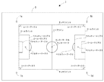
また、設営画像描画部365は、図6に示すような、選択された作業者の進捗状況を通知する進捗画面40を生成し、生成した進捗画面40をAR画像内に配置させる。進捗画面40は、設営するラインの全体像に、全作業者のそれぞれ位置と、選択された作業者が設営を担当するラインパーツと、他の作業者が設営を担当するラインパーツとが反映されていると共に、選択された作業者の進捗率が進捗バーとして表示される。また、進捗画面40には、計画データ8の順番に基づき、次のラインパーツへの移動を示す情報が矢印等で表示される。図6に示す進捗画面40は、A氏の進捗画面40であり、A氏が設営を担当するラインパーツ(設営済みライン上の案内ラインが実線、ラインが引かれていない箇所の案内ラインが点線)が太く強調表示されていると共に、B氏の担当分の案内ラインが一点鎖線で、C氏の担当分の案内ラインが点線でそれぞれ表示されている。
The setup
次に、本実施の形態の設営アシストシステムによる設営アシスト動作について図4乃至8を参照して詳細に説明する。なお、図4に示す設営データ7と、図5に示す計画データ8とが設営プラン管理装置2によって作成されているものとして以下説明する。
Next, the setting assistance operation by the setting assistance system of the present embodiment will be described in detail with reference to FIGS. 4 to 8. In the following description, it is assumed that the
まず、設営データ7における基準ポール1a〜1dのそれぞれ配置位置に、実際の基準ポール1a〜1dを会場Gにそれぞれ設置する。基準ポール1a〜1dのそれぞれ設置位置は、実測データ5内の既知点として機能する。基準ポール1a〜1dは、基体部11の中心軸が垂直になるように設置する。これにより、基準ポール1a〜1dをどの方向から見ても条件が同じになる。なお、基体部11の中心軸をできるだけ正確に垂直に設置した方が好ましいが、厳密な垂直でなくても一定の効果が得られることは言うまでもない。
First,
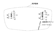
次に、作業者は、メガネ型端末3を装着し、4本の基準ポール1a〜1dの内の少なくとも2本を視界に捉える。これにより、視界撮像部31によって、図7に示すように、4本の基準ポール1a〜1dの内の少なくとも2本が含まれる視界画像が撮像される。以下、図7に示すように、基準ポール1bと、基準ポール1dとが視界画像に含まれた例について説明する。
Next, the worker wears the glasses-
視界画像内の基準ポール1bと、基準ポール1dとは、基準ポール検出部361によって検出される。基準ポール検出部361は、視界画像において、基準データ4の照合データと一致する識別部14を検索することで、基準ポール1bと、基準ポール1dとを区別して検出する。
The
現在位置特定部362は、基準ポール検出部361によって2本の基準ポール1bと、基準ポール1dとが検出されると、検出された基準ポール1bと、基準ポール1dとを用いて、実測データ5内におけるメガネ型端末3の現在位置及び姿勢を現在位置情報として特定する。
The current
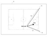
現在位置特定部362は、視界画像内の基準ポール1bの基体長Xbと、基準データ4の基準ポール1bの基体長Xとに基づいて、基準ポール1bとの距離Lbを算出すると共に、視界画像内の基準ポール1dの基体長Xdと、基準データ4の基準ポール1dの基体長Xとに基づいて、基準ポール1dとの距離Ldを算出する。これにより、図8に示すように、会場G(実測データ5)内におけるメガネ型端末3の現在位置が特定される。
The current
また、現在位置特定部362は、基準ポール1bもしくは基準ポール1dの視界画像内の左右方向の位置に基づいて、メガネ型端末3が向いている方角を特定する。さらに、現在位置特定部362は、基準ポール1bもしくは基準ポール1dの視界画像内の上下方向の位置に基づいて、メガネ型端末3が向いている傾きを特定する。なお、現在位置特定部362は、加速度センサー37及び電子コンパス38の出力によって、メガネ型端末3が向いている姿勢を特定するようにしても良い。
Further, the current
視界画像に4本の基準ポール1a〜1dの内の少なくとも2本が含まれている間、現在位置特定部362による現在位置情報の特定は、作業員の移動や視線の変化に応じて随時行われる。そして、視界画像に含まれる基準ポール1a〜1dが2本未満になると、また、現在位置特定部362は、加速度センサー37の出力と、電子コンパス38の出力とに基づいて、現在位置情報を追従して推定する。
While at least two of the four
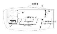
設営画像描画部365は、現在位置特定部362によって特定もしくは推定された現在位置情報と、設営データ7とに基づいて、案内ラインをAR画像として描画し、図9に示すように、AR画像表示部32に表示させる。図9に示すAR画像例は、A氏用のAR画像であり、A氏が設営を担当するラインパーツ(ラインが引かれていない箇所の案内ラインが点線)が太く強調表示されていると共に、B氏担当分の設置済みライン上の案内ラインが細い実線で、エラーライン上の案内ラインが細い一点鎖線でそれぞれ表示されている。なお、設置済みラインは視界画像に存在しているため、AR画像において該当箇所の案内ラインを省略しても良い。また、AR画像において設置済みライン上に案内ラインを表示させる場合には、視界画像の設置済みラインとは異なる色で表示させると良い。
The construction
ライン引きを行う場合、AR画像表示部32には作業者の視界に重畳して案内ラインがAR画像として表示される。従って、作業者はAR画像に合わせてラインカーでラインを引くことができる。なお、ラインカーは通常前押しで使用されるが、その場合、振り返ると引いた白線と白線のAR画像が重なって見えるので、正しく引けたかどうか確認できる。
When line drawing is performed, the guidance line is displayed as an AR image on the AR
また、AR画像において、図9に示すように、正しい寸法、濃度もしくは配置で引かれていないエラーライン上の案内ラインが他の箇所と区別して描画されている。従って、会場Gを見渡すだけで、補修する必要がある箇所を簡単に把握することができる。例えば、競技と競技の間といった限られた短時間でライン補修を完了しなければならない場合、全てのラインを引き直す必要はなく、補修する必要がある部分と、補修する必要が無い部分を明確にAR画像表示部32上に表示することにより、より効率化を図ることができる。
Further, in the AR image, as shown in FIG. 9, a guide line on an error line which is not drawn with the correct size, density or arrangement is drawn in distinction from other places. Therefore, only by looking over the place G, it is possible to easily grasp the location which needs to be repaired. For example, if it is necessary to complete the line repair in a limited short time, such as between competitions, it is not necessary to redraw all the lines, and clearly identify the parts that need to be repaired and the parts that do not need to be repaired. By displaying on the AR
なお、本実施の形態では、4本の基準ポール1a〜1dを設置するように構成したが、上述のように、基準ポールは2本以上であれば良く、会場Gに設置する基準ポールの本数は会場Gに応じて適宜設定すると良い。
In the present embodiment, four
本実施の形態では、基準ポール1a〜1dのそれぞれ設置位置を、実測データ5内の既知点としている。従って、基準ポール1a〜1dを設営データ7の通りに正確に設置しなければならない。しかし、基準ポール1a〜1dの設置位置をそれぞれ正確に測定することは手間のかかる作業となる。
In the present embodiment, the installation positions of the
そこで、現在位置情報に基づいて実測データ5の輪郭、すなわち会場Gの輪郭をAR画像として描画する機能を設営画像描画部365に備えることで、設置位置を正確に測定することなく、基準ポール1a〜1dを設営データ7の通りに正確に設置することが可能になる。以下に、その手順を示す。
Therefore, by providing the setting
まず、作業者は、基準ポール1a〜1dの内の2本、例えば、基準ポール1a、1bを設営データ7の設定位置に目測でそれぞれ設置する。次に、作業者は、メガネ型端末3を装着し、2本の基準ポール1a、1bを視界に捉える。これにより、現在位置特定部362は、基準ポール1a、1bが正確に設置されているとした仮の現在位置情報を特定する。
First, the operator visually installs two of the
次に、設営画像描画部365は、仮の現在位置情報に基づいて実測データ5の輪郭を描画してAR画像表示部32に表示させる。
Next, the construction
これにより、作業者は、会場Gの輪郭のAR画像と、実際の会場Gの輪郭とのズレを認識することができる。そして、両者が一致するように、基準ポール1a、1bの設置位置を調整することで、基準ポール1a、1bは設営データ7の通りに正確に設置される。
As a result, the worker can recognize the deviation between the AR image of the contour of the venue G and the contour of the actual venue G. Then, by adjusting the installation positions of the
他の2本の基準ポール1c、1dについては、基準ポール1a、1bを用いることで正確な現在地情報が特定されるため、設営画像描画部365によって描画させた基準ポール1c、1dのAR画像を用いて設置することができる。
As for the other two
さらに、本実施の形態では、メガネ型端末3に端末記憶部34と、基準ポール検出部361、現在位置特定部362、設営検証部363、進捗管理部364及び設営画像描画部365とを設けた例について説明したが、これらの構成の全部もしくは一部を、メガネ型端末3と通信可能な設営プラン管理装置2やネットワーク上の設けるようにしても良い。
Furthermore, in the present embodiment, the glasses type terminal 3 is provided with the
以上説明したように、本実施の形態によれば、会場Gにラインを設営する作業者を、作業者の前方視界を撮像する視界撮像部31と、作業者の前方視界に重畳されて表示されるAR画像表示部32とを備えたメガネ型端末3を用いてアシストする設営アシストシステムであって、既知長の基体部11を有し、会場Gの複数の既知点にそれぞれ設置された複数の基準ポール1a〜1dと、会場Gの実測データ5に基準ポール1a〜1d及びラインの位置がレイアウトされた設営データ7を記憶する端末記憶部34と、視界撮像部31によって撮像された視界画像内の基準ポール1a〜1dを検出する基準ポール検出部361と、基準ポール検出部361によって複数の基準ポール1a〜1d内の2本以上が検出されると、視界画像内の基準ポール1a〜1dの大きさ及び位置に基づいて、実測データ5内におけるメガネ型端末3の現在位置及び姿勢を現在位置情報として特定する現在位置特定部362と、視界画像を解析することで会場Gに引かれている設営済みラインを特定する設営検証部363と、現在位置情報及び設営データ7に基づいて、ラインの設営位置を案内する案内ラインをAR画像として描画してAR画像表示部32に表示させる設営画像描画部365と、を具備し、設営画像描画部365は、設営済みライン上の案内ラインと、ラインが引かれていない箇所の案内ラインとを区別して描画する。
この構成により、作業者の視界にこれから設営すべきラインの拡張現実画像を重畳させて表示することができるため、作業者は拡張現実画像を見ながらライン引きを行うことができ、会場の設営を行う作業者を効率的にアシストすることができる。
As described above, according to the present embodiment, the operator who sets up a line at the venue G is displayed by being superimposed on the visual
With this configuration, the augmented reality image of the line to be set up can be superimposed and displayed on the field of view of the worker, so that the worker can draw a line while looking at the augmented reality image, thus setting up the venue It is possible to efficiently assist the operator who performs.
さらに、本実施の形態によれば、設営検証部363は、設営済みラインと、設営データ7とを比較し、正しくラインが引かれているか否かを判断し、設営画像描画部365は、正しく引かれていない設営済みライン上の案内ラインを他の箇所と区別して描画する。
この構成により、会場Gを見渡すだけで、補修する必要がある箇所を簡単に把握することができ、より効率化を図ることができる。
Further, according to the present embodiment, the
With this configuration, it is possible to easily grasp a part that needs to be repaired by looking over the hall G, and to achieve more efficiency.
さらに、本実施の形態によれば、前記ラインの設営を担当する作業者が前記ラインを分割したラインパーツ毎に設定された計画データ8を記憶する端末記憶部34と、作業者の選択を受け付ける操作部35と、を具備し、設営画像描画部365は、案内ラインにおいて、選択された作業者が設営を担当するラインパーツを他の作業者の担当分と区別して描画する。
この構成により、選択された作業者の担当分を簡単に把握することができる。
Furthermore, according to the present embodiment, the worker in charge of setting up the line receives the selection of the worker, the
According to this configuration, it is possible to easily grasp what the selected worker is in charge of.
さらに、本実施の形態によれば、設営済みラインのライン長をラインパーツ毎に算出し、作業者毎の進捗率を算出する進捗管理部364を具備し、設営画像描画部365は、選択された作業者の進捗率を通知する進捗画面40を生成してAR画像内に配置させる。
この構成により、選択された作業者の進捗状況を簡単に把握することができる。
Furthermore, according to the present embodiment, the
This configuration makes it possible to easily grasp the progress of the selected worker.
なお、本発明が上記各実施の形態に限定されず、本発明の技術思想の範囲内において、各実施の形態は適宜変更され得ることは明らかである。 The present invention is not limited to the above embodiments, and it is apparent that each embodiment can be appropriately modified within the scope of the technical idea of the present invention.
1a〜1d 基準ポール
2 設営プラン管理装置
3 メガネ型端末
4 基準データ
5 実測データ
6 ラインデータ
7 設営データ
8 計画データ
11 基体部
12 足部
13 計測基準部
14 識別部
21 本体表示部
22 本体入力部
23 本体記憶部
24 本体通信部
25 本体制御部
31 視界撮像部
32 AR画像表示部
33 端末通信部
34 端末記憶部
35 操作部
36 端末制御部
37 加速度センサー
38 電子コンパス
40 進捗画面
251 設営データ生成部
252 計画データ生成部
361 基準ポール検出部
362 現在位置特定部
363 設営検証部
364 進捗管理部
365 設営画像描画部
1a to
Claims (4)
既知長の基体部を有し、前記会場の複数の既知点にそれぞれ設置された複数の基準ポールと、
前記会場の実測データに前記基準ポール及び前記ラインの位置がレイアウトされた設営データを記憶する設営データ記憶部と、
前記視界撮像部によって撮像された視界画像内の前記基準ポールを検出する基準ポール検出部と、
前記基準ポール検出部によって複数の前記基準ポールが検出されると、視界画像内の前記基準ポールの大きさ及び位置に基づいて、前記実測データ内における前記メガネ型端末の現在位置及び姿勢を現在位置情報として特定する現在位置特定部と、
前記視界画像を解析することで前記会場に引かれている設営済みラインを特定する設営検証部と、
前記現在位置情報及び前記設営データに基づいて、前記ラインの設営位置を案内する案内ラインを拡張現実画像として描画して前記画像表示部に表示させる設営画像描画部と、を具備し、
前記設営画像描画部は、前記設営済みライン上の前記案内ラインと、前記ラインが引かれていない箇所の前記案内ラインとを区別して描画することを特微とする設営アシストシステム。 Using a glasses-type terminal provided with a worker who sets up a line in a hall, a vision imaging unit for imaging the worker's vision in front, and an image display unit displayed superimposed on the worker's vision in front A construction assistance system that assists in
A plurality of reference poles each having a base portion of a known length and installed respectively at a plurality of known points of the hall;
A construction data storage unit for storing construction data in which the positions of the reference pole and the line are laid out in actual measurement data of the hall;
A reference pole detection unit that detects the reference pole in the view image captured by the view imaging unit;
When a plurality of reference poles are detected by the reference pole detection unit, the current position and orientation of the glasses-type terminal in the actual measurement data are determined based on the size and position of the reference poles in the view image. A current position identification unit identified as information;
A construction verification unit that specifies a constructed line drawn to the hall by analyzing the visibility image;
A guidance image drawing unit for drawing a guidance line guiding the setting position of the line as an augmented reality image based on the current position information and the setting data, and displaying the same on the image display unit;
The establishment assisting system, wherein the establishment image drawing unit draws the guide line on the established line and the guide line at a place where the line is not drawn separately.
前記設営画像描画部は、正しく引かれていない前記設営済みライン上の前記案内ラインを他の箇所と区別して描画することを特微とする請求項1記載の設営アシストシステム。 The construction verification unit compares the construction line with the construction data to determine whether the construction line is correctly drawn or not.
The establishment assisting system according to claim 1, wherein the establishment image drawing unit draws the guide line on the installation line which is not drawn correctly, separately from other places.
前記作業者の選択を受け付ける操作部と、を具備し、
前記設営画像描画部は、前記案内ラインにおいて、選択された作業者が設営を担当するラインパーツを他の作業者の担当分と区別して描画することを特微とする請求項1又は2記載の設営アシストシステム。 A plan data storage unit for storing plan data set for each line part obtained by dividing the line by a worker who is in charge of setting up the line;
And an operation unit that receives the selection of the worker.
The setting image drawing unit according to claim 1 or 2, wherein in the guide line, the selected worker draws a line part which is in charge of setting, while distinguishing it from other workers. Construction assistance system.
前記設営画像描画部は、選択された作業者の進捗率を通知する進捗画面を生成して前記拡張現実画像内に配置させることを特微とする請求項3記載の設営アシストシステム。 And a progress management unit that calculates the line length of the established line for each of the line parts, and calculates a progress rate for each of the workers,
The establishment assisting system according to claim 3, wherein the establishment image drawing unit generates a progress screen for notifying a progress rate of the selected worker and arranges the progress screen in the augmented reality image.
Priority Applications (1)
| Application Number | Priority Date | Filing Date | Title |
|---|---|---|---|
| JP2017084347A JP6597702B2 (en) | 2017-04-21 | 2017-04-21 | Setup assist system |
Applications Claiming Priority (1)
| Application Number | Priority Date | Filing Date | Title |
|---|---|---|---|
| JP2017084347A JP6597702B2 (en) | 2017-04-21 | 2017-04-21 | Setup assist system |
Publications (2)
| Publication Number | Publication Date |
|---|---|
| JP2018181237A true JP2018181237A (en) | 2018-11-15 |
| JP6597702B2 JP6597702B2 (en) | 2019-10-30 |
Family
ID=64276899
Family Applications (1)
| Application Number | Title | Priority Date | Filing Date |
|---|---|---|---|
| JP2017084347A Expired - Fee Related JP6597702B2 (en) | 2017-04-21 | 2017-04-21 | Setup assist system |
Country Status (1)
| Country | Link |
|---|---|
| JP (1) | JP6597702B2 (en) |
Cited By (2)
| Publication number | Priority date | Publication date | Assignee | Title |
|---|---|---|---|---|
| CN111896034A (en) * | 2020-08-06 | 2020-11-06 | 深圳市兆威机电股份有限公司 | In-place detection method, device, controller and storage medium |
| JP7682390B1 (en) * | 2023-10-12 | 2025-05-23 | 三菱電機株式会社 | Work support device, work support method, and work support system |
Citations (7)
| Publication number | Priority date | Publication date | Assignee | Title |
|---|---|---|---|---|
| JP2002136636A (en) * | 2000-10-30 | 2002-05-14 | Bunsaku Kamatsuka | Line drawing device |
| JP2008243166A (en) * | 2007-03-28 | 2008-10-09 | Age System Kk | Autonomously traveling type line car |
| JP2009069954A (en) * | 2007-09-11 | 2009-04-02 | National Institute Of Advanced Industrial & Technology | Work support device |
| JP2012212991A (en) * | 2011-03-30 | 2012-11-01 | Brother Ind Ltd | Head-mounted display |
| JP2013540047A (en) * | 2010-09-22 | 2013-10-31 | ヘキサゴン・テクノロジー・センター・ゲーエムベーハー | Surface sputtering equipment |
| JP2014010810A (en) * | 2012-07-03 | 2014-01-20 | Takaaki Kasuga | Work system by self-propelled apparatus |
| JP2016138908A (en) * | 2015-01-26 | 2016-08-04 | セイコーエプソン株式会社 | Display system, portable display device, display control device, and display method |
-
2017
- 2017-04-21 JP JP2017084347A patent/JP6597702B2/en not_active Expired - Fee Related
Patent Citations (7)
| Publication number | Priority date | Publication date | Assignee | Title |
|---|---|---|---|---|
| JP2002136636A (en) * | 2000-10-30 | 2002-05-14 | Bunsaku Kamatsuka | Line drawing device |
| JP2008243166A (en) * | 2007-03-28 | 2008-10-09 | Age System Kk | Autonomously traveling type line car |
| JP2009069954A (en) * | 2007-09-11 | 2009-04-02 | National Institute Of Advanced Industrial & Technology | Work support device |
| JP2013540047A (en) * | 2010-09-22 | 2013-10-31 | ヘキサゴン・テクノロジー・センター・ゲーエムベーハー | Surface sputtering equipment |
| JP2012212991A (en) * | 2011-03-30 | 2012-11-01 | Brother Ind Ltd | Head-mounted display |
| JP2014010810A (en) * | 2012-07-03 | 2014-01-20 | Takaaki Kasuga | Work system by self-propelled apparatus |
| JP2016138908A (en) * | 2015-01-26 | 2016-08-04 | セイコーエプソン株式会社 | Display system, portable display device, display control device, and display method |
Cited By (2)
| Publication number | Priority date | Publication date | Assignee | Title |
|---|---|---|---|---|
| CN111896034A (en) * | 2020-08-06 | 2020-11-06 | 深圳市兆威机电股份有限公司 | In-place detection method, device, controller and storage medium |
| JP7682390B1 (en) * | 2023-10-12 | 2025-05-23 | 三菱電機株式会社 | Work support device, work support method, and work support system |
Also Published As
| Publication number | Publication date |
|---|---|
| JP6597702B2 (en) | 2019-10-30 |
Similar Documents
| Publication | Publication Date | Title |
|---|---|---|
| US20240362918A1 (en) | Surveillance information generation apparatus, imaging direction estimation apparatus, surveillance information generation method, imaging direction estimation method, and program | |
| US8472703B2 (en) | Image capture environment calibration method and information processing apparatus | |
| JP5762892B2 (en) | Information display system, information display method, and information display program | |
| JP6598617B2 (en) | Information processing apparatus, information processing method, and program | |
| CN107402000B (en) | Method and system for correlating a display device with respect to a measurement instrument | |
| US10074179B2 (en) | Image measurement device | |
| JP6016268B2 (en) | Field work support device, method and program | |
| JP4537557B2 (en) | Information presentation system | |
| JP2021192304A (en) | Information processing equipment, its control method, and programs | |
| US10950057B2 (en) | Virtual spatially registered video overlay display | |
| JP2002259976A (en) | Method and device for detecting specific point | |
| WO2007111241A1 (en) | Road video image analyzing device and road video image analyzing method | |
| US6810142B2 (en) | Stereo image measuring device | |
| JP6323025B2 (en) | Display control program, display control device, and display control system | |
| JP2020098451A (en) | Information projection system, control device, and information projection method | |
| JPWO2019059091A1 (en) | Utility pole management system | |
| TW201429239A (en) | Field display system, field display method, and computer-readable recording medium in which field display program is recorded | |
| JP6597702B2 (en) | Setup assist system | |
| KR20200094941A (en) | Method for recognizing worker position in manufacturing line and apparatus thereof | |
| US7409152B2 (en) | Three-dimensional image processing apparatus, optical axis adjusting method, and optical axis adjustment supporting method | |
| JP2017062748A (en) | Alignment device, alignment method, and alignment program | |
| JP2017147689A (en) | Video editing apparatus, video editing method, and video editing computer program | |
| JP2018106358A (en) | Setup assisting system | |
| JP2019185475A (en) | Specification program, specification method, and information processing device | |
| JP2007212187A (en) | Stereo photo measuring device, stereo photo measuring method, and stereo photo measuring program |
Legal Events
| Date | Code | Title | Description |
|---|---|---|---|
| A621 | Written request for application examination |
Free format text: JAPANESE INTERMEDIATE CODE: A621 Effective date: 20190128 |
|
| A977 | Report on retrieval |
Free format text: JAPANESE INTERMEDIATE CODE: A971007 Effective date: 20190822 |
|
| TRDD | Decision of grant or rejection written | ||
| A01 | Written decision to grant a patent or to grant a registration (utility model) |
Free format text: JAPANESE INTERMEDIATE CODE: A01 Effective date: 20190903 |
|
| A61 | First payment of annual fees (during grant procedure) |
Free format text: JAPANESE INTERMEDIATE CODE: A61 Effective date: 20190916 |
|
| R150 | Certificate of patent or registration of utility model |
Ref document number: 6597702 Country of ref document: JP Free format text: JAPANESE INTERMEDIATE CODE: R150 |
|
| LAPS | Cancellation because of no payment of annual fees |