JP2018175730A - Nitrogen infrastructure system - Google Patents
Nitrogen infrastructure system Download PDFInfo
- Publication number
- JP2018175730A JP2018175730A JP2017084042A JP2017084042A JP2018175730A JP 2018175730 A JP2018175730 A JP 2018175730A JP 2017084042 A JP2017084042 A JP 2017084042A JP 2017084042 A JP2017084042 A JP 2017084042A JP 2018175730 A JP2018175730 A JP 2018175730A
- Authority
- JP
- Japan
- Prior art keywords
- nitrogen
- hydrogen
- infrastructure
- area
- building
- Prior art date
- Legal status (The legal status is an assumption and is not a legal conclusion. Google has not performed a legal analysis and makes no representation as to the accuracy of the status listed.)
- Granted
Links
Images


Classifications
-
- Y—GENERAL TAGGING OF NEW TECHNOLOGICAL DEVELOPMENTS; GENERAL TAGGING OF CROSS-SECTIONAL TECHNOLOGIES SPANNING OVER SEVERAL SECTIONS OF THE IPC; TECHNICAL SUBJECTS COVERED BY FORMER USPC CROSS-REFERENCE ART COLLECTIONS [XRACs] AND DIGESTS
- Y02—TECHNOLOGIES OR APPLICATIONS FOR MITIGATION OR ADAPTATION AGAINST CLIMATE CHANGE
- Y02E—REDUCTION OF GREENHOUSE GAS [GHG] EMISSIONS, RELATED TO ENERGY GENERATION, TRANSMISSION OR DISTRIBUTION
- Y02E60/00—Enabling technologies; Technologies with a potential or indirect contribution to GHG emissions mitigation
- Y02E60/30—Hydrogen technology
- Y02E60/34—Hydrogen distribution
Abstract
Description
本発明は、来るべき水素社会の到来に備え水素に起因する火災・爆発災害を防止するため新たに導管を用いた窒素インフラを構築して水素インフラに付加し、水素による災害を未然に防止すると共に構築された窒素インフラを物流倉庫等に代表される大型の密閉型建屋の防消火設備として使用する手段を提供する。 The present invention is to prepare for the coming of the coming hydrogen society, construct a new nitrogen infrastructure using a conduit to prevent a fire and explosion disaster caused by hydrogen, add it to the hydrogen infrastructure, and prevent the disaster caused by hydrogen in advance. Provide a means to use the built-in nitrogen infrastructure as a fireproof and extinguishing facility for large-scale enclosed buildings represented by logistics warehouses.
次世代のクリーンエネルギーとして期待される水素は地球温暖化防止に向けたクリーン・ガスとして新しい用途の開発が進んでいる。中でも燃料電池車向けの水素は既に実用車が市販され実用化の段階を迎えている。一方、需要拡大への最大の課題は燃料電池車へ水素を供給するための水素ステ−ションの整備であるといわれている。本発明の窒素インフラの構築はこの水素ステーション向けの水素インフラと密接に関係する。 Hydrogen, which is expected as the next generation clean energy, is being developed as a clean gas for preventing global warming. Above all, hydrogen for fuel cell vehicles has already been commercialized and is in the stage of practical use. On the other hand, it is said that the biggest issue for expanding demand is the maintenance of a hydrogen station for supplying hydrogen to fuel cell vehicles. The construction of the nitrogen infrastructure of the present invention is closely related to the hydrogen infrastructure for this hydrogen station.
最初に窒素インフラの構築に不可欠な水素ステーション向けの水素インフラの現状を記す。水素ステーションは水素製造所と水素充填所の存在場所により、オンサイト型とオフサイト型に区分される。オンサイト型とは、両者が同一場所にあるステーションを指し、オフサイト型は充填所から離れた場所で水素を製造する方式を指す。 First, we describe the current status of hydrogen infrastructure for hydrogen stations, which is essential for the construction of nitrogen infrastructure. Hydrogen stations are divided into on-site type and off-site type depending on the location of hydrogen production site and hydrogen filling site. The on-site type refers to a station in which both are in the same place, and the off-site type refers to a method of producing hydrogen at a location remote from the filling station.
両者は製造場所の立地条件や水素の輸送方法で各々長所短所があり、現時点でどちらの方式が優位かについて結論は出ていない。オフサイト型の水素ステーションについては水素を集中して大量に製造でき水素の製造コストを安くできる利点があるが、水素製造所から水素ステーションまで水素を輸送しなければならない。 Both have their advantages and disadvantages in terms of the location conditions of the production site and the method of transport of hydrogen, and no conclusion has been reached as to which method is superior at this time. The off-site hydrogen station has the advantage of being able to concentrate and produce a large amount of hydrogen and reduce the cost of hydrogen production, but it must be transported from the hydrogen plant to the hydrogen station.
水素の輸送方法として水素ガスを高圧ボンベに充填し専用の車両で運ぶ方法、水素を液化し液化水素ローリ車で運ぶ方法及び導管を用いてガス状態で運ぶ方法がある。本発明ではこの中から導管を使用する方法を選び、この導管輸送による水素インフラの存在を前提に新たな提案を行う。 Methods of transporting hydrogen include a method of filling hydrogen gas into a high pressure cylinder and transporting it by a dedicated vehicle, a method of liquefying hydrogen and transporting it by a liquefied hydrogen rally vehicle, and a method of transporting it in a gaseous state using a conduit. In the present invention, a method of using a conduit is selected from these, and a new proposal is made on the premise of the existence of a hydrogen infrastructure by this conduit transportation.
実際に導管を使用して水素ステーションへ水素を供給する方式は2011年に水素・燃料電池実証プロジェクトの一環として北九州市で試行された。この水素ステーションでは隣接する製鉄所で副生した水素から製造された純水素を地上に敷設した導管を使用して受け入れた。導管の長さは全長で約2kmである。同プロジェクトはこの方式を「導管を使用した日本初の次世代型水素ステーション」として紹介した。 In fact, a method of supplying hydrogen to a hydrogen station using a conduit was tried in Kitakyushu City in 2011 as part of a hydrogen fuel cell demonstration project. At this hydrogen station, pure hydrogen produced from hydrogen by-produced at an adjacent steel mill was received using a conduit laid on the ground. The length of the conduit is about 2 km in total length. The project introduced this method as "the first-generation hydrogen station in Japan using a conduit".
本提案の第一目標はこの水素の導管中に窒素を添加して水素・窒素の混合ガスとして輸送された窒素を利用し、新たな窒素インフラを構築して水素による火災・爆発災害を未然に防止するものである。以下にその背景を記す。 The first goal of this proposal is to add nitrogen into this hydrogen conduit and use nitrogen transported as a mixed gas of hydrogen and nitrogen to construct a new nitrogen infrastructure to prevent fires and explosion hazards caused by hydrogen To prevent. The background is described below.
可燃性ガスの爆発・火災の危険性を回避するため窒素を用いることは古くから化学工業界では活用されている方法である。この理由は特に水素の場合、空気中での爆発範囲が広いこと、着火エネルギーが小さいこと、燃焼速度が速いこと等極めて燃え易いガスのため、窒素を添加して水素の危険度を安全側に移行させるためである。 The use of nitrogen to avoid the danger of explosion and fire of flammable gas has long been used in the chemical industry. The reason for this is that, particularly in the case of hydrogen, the explosion range in air is wide, the ignition energy is small, the combustion speed is fast, and so on. Nitrogen is added to make the safety of hydrogen dangerous by adding nitrogen. It is for moving.
水素の輸送に導管を使用する方法は欧米では既に実績があり、我が国でも石油コンビナート等の企業間においてその流通に使われている。しかし水素を単独とせず水素・窒素の混合ガスとして輸送する方法は化学工場のアンモニア・プラント設備の一部で使われているが、その活用方法は限定されており、市街地を含む広域な地域で実施されたことは国内は無論のこと世界でも例はない。 The method of using a conduit to transport hydrogen has already been proven in Europe and the United States, and it is used for distribution among companies such as petroleum complexes in Japan. However, the method of transporting hydrogen as a mixed gas of hydrogen and nitrogen instead of using it alone is used in a part of the ammonia plant facility of a chemical plant, but the method of using it is limited, and in a wide area including urban area What has been implemented is, of course, nowhere in the world in the world.
一方で水素中に窒素を混入させて水素輸送の安全性を高めようとする試みは最近になり見直しが行われ、幾つかの新たな提案がある。 導管を使用して水素を水素・窒素の混合ガスとして輸送する方法として次の文献が公開されている。
文献1,2には水素の爆発危険性を回避するため、水素を単独ではなく水素・窒素の混合ガスとして輸送する方法が記載されている。 文献3には水素ステーションで水素・窒素の混合ガスから水素と窒素を簡便な方法で分離する方法が記載されている。文献4では導管からの水素ガスの漏洩を監視するため、導管から漏れた水素の検知方法が記載されている
特許文献1〜4に示す方法で水素インフラを構築する場合限定された地域おいて実施する場合は極めて有効である。例えば国内において北九州市から山陽道、近畿、東海を経て関東に至る経路は我が国屈指の人口過密地帯であり上記の特許文献に示す輸送方法はその対応に適している。 In the case of constructing a hydrogen infrastructure by the methods shown in
一方で国内で東北、北海道地方更に世界規模、例えば広大な国土を有する米国や中国等で上記の方法を展開する場合はこれらの地域では水素製造所と消費先が荒野を挟んで数十キロ以上離れているケースも稀ではない。これ等の全ての地域までも水素に市街地並みの窒素を混合する試みは危険度への対応として過剰であり、適切ではない。 On the other hand, if the above method is developed in Tohoku, Hokkaido, and other regions on a global scale, for example, the United States and China, etc., which have a large land area, hydrogen plants and consumers in these areas dozens of kilometers over the wilderness It is not uncommon for cases to be separated. Even in all these areas, attempts to mix urban area nitrogen with hydrogen are excessive and not appropriate for dealing with the degree of risk.
この考えは水素インフラに付加する窒素インフラの構築についても同様である。即ち、新しく構築される窒素インフラは対象とする地域の特性を考慮してその地域に最もふさわしい安全対策を実施することが重要である。 更に構築された窒素インフラは水素ステーションの安全対策だけに限定せず、従来にない新しい用途を付加する必要がある。 The same is true for the construction of nitrogen infrastructure to be added to hydrogen infrastructure. In other words, it is important to implement the most appropriate security measures for the newly constructed nitrogen infrastructure in consideration of the characteristics of the targeted area. Furthermore, the constructed nitrogen infrastructure is not limited to the safety measures of the hydrogen station, and it is necessary to add new applications that have not been made before.
本提案の第二目標は水素インフラに付加して構築された窒素インフラを導管を用いて広範囲な地域において新たなタイプの防消火設備として活用する。以下にその背景を記す。 The second goal of the proposal is to use a nitrogen infrastructure built by adding hydrogen infrastructure as a new type of fire extinguishing system in a wide area using a conduit. The background is described below.
美術館や博物館等で使用される消火設備では貴重な美術品が水消火により損傷されることを避けるため窒息性ガスを吹込んで消火させる設備は既に実用化されている。窒息性ガスとして実績あるガスはハロゲン系ガスと窒素である。これ等のガスは通常は専用ボンベに充填し消火を対象とする建屋の近傍に保管され万一の発災時にはここから火災の発生場所へ向け放出される。 In fire extinguishing equipment used in museums and the like, equipment for blowing in suffocating gas and extinguishing the fire has already been put to practical use in order to prevent damage to valuable works of art by water extinguishing. The gases proven as asphyxiogenic gases are halogen-based gases and nitrogen. These gases are usually filled in a special cylinder and stored in the vicinity of a building for fire extinguishing, and are released to the place where the fire occurs in case of a disaster.
建屋内に窒素を吹き込み内部の酸素濃度を下げる場合、内部の空気は窒素とほぼ均一に混合し、排気口を経由して大気に放散される。学術的にはこの混合を「完全混合」と呼ぶ。
建屋内部の酸素濃度は徐々に低下し、可燃性ガスが燃焼できない濃度に達する。この時の酸素濃度を「限界酸素濃度」という。この値は可燃性ガスによって固有の値を持ち、水素の場合5.0%、メタンでは12.1%である。When nitrogen is blown into the building to lower the oxygen concentration inside, the internal air mixes almost uniformly with the nitrogen and is dissipated to the atmosphere via the exhaust port. Academically, this mixing is called "perfect mixing".
The oxygen concentration in the interior of the building gradually decreases and reaches a concentration at which the combustible gas can not burn. The oxygen concentration at this time is called "limit oxygen concentration". This value is specific to the flammable gas and is 5.0% for hydrogen and 12.1% for methane.
可燃物が液体や固体の場合も高温により液体の蒸発や固体の分解で可燃性ガスを発生させるので、窒素を使用してその燃焼を止めるためには気体の場合と同様に建屋内の酸素濃度が可燃性ガスの限界酸素濃度以下になるまで窒素を吹き込めば良い。また窒素を大量に吹き込む場合は、建屋内が過圧にならないよう、建屋内のガスを十分に排気できる排気経路を確保することが必要である。 Even if the flammable matter is liquid or solid, the high temperature generates a flammable gas by evaporation of the liquid or decomposition of the solid. Therefore, to stop the combustion using nitrogen, the oxygen concentration in the building is the same as the gas. Nitrogen may be blown in until the oxygen concentration of the flammable gas is below the limit. In the case of blowing a large amount of nitrogen, it is necessary to secure an exhaust path which can exhaust the gas in the building sufficiently so that the pressure in the building will not be overpressured.
通常ボンベに貯蔵可能なガス量は数m3/本であるから、消火対象とする建屋の容量は概ね数10m3〜100m3程度に限定される。このため従来の消火対象は建屋全体ではなく、建屋の中で最も貴重な美術品を収納する部屋に限定せざるを得なかった。 従ってこれ等の窒息性ガスによる消火設備を美術館全館や容積で数千m3規模の物流倉庫等の大型建屋を対象としてする試みは未だ公開されていない。Since the amount of gas that can be stored in a normal cylinder is several m 3 / present, the capacity of the building to be fire fighting subject is generally limited to about several 10m 3 ~100m 3. For this reason, the conventional fire extinguishing object was not limited to the whole building, but it had to be limited to the room for storing the most valuable works of art in the building. Thus attempts to large buildings, such as several thousand m 3 scale warehouse as target museums entire or volume of fire extinguishing facility according to suffocating gases which such has not yet been published.
上記の消火対象となる建屋としては通販向けの大型物流倉庫に加えて、貴重な絵画を所有する美術館、可燃性美術品を収納す博物館、金色堂に代表される神社・仏閣、内部で塗料等可燃性危険物を取り扱う工場、更に事故時に可燃性ガスを発生する恐れのある密閉型建屋等広範囲な建屋が挙げられる。 In addition to large-scale distribution warehouses for mail order as buildings subject to the above-mentioned fire extinguishing, museums that possess valuable pictures, museums that hold combustible works, shrines and temples typified by the Golden Hall, paints etc. inside There are a wide range of buildings such as factories that handle flammable materials, and closed buildings that may generate flammable gas in the event of an accident.
これ等の対象物は従来の消火方法では煙検知器とスプリンクラーを組み合わせた水消火を基本としており建屋全域をカバーするには対処が困難で、これに代わる新たな消火設備が切望されていた。本発明はこの課題に対し既存の対応を一新させる有効でかつ独創的な手段を提供する。 These objects are based on water fire extinguishing combined with a smoke detector and a sprinkler in the conventional fire extinguishing method, and it is difficult to cope with covering the entire building area, and a new fire extinguishing system has been desired. The present invention provides an effective and inventive means to renew the existing solution to this problem.
一方で本発明を全国規模で利用する際、特に注意しなければならない重要な課題は酸欠症即ち酸素欠乏に伴う人的災害や事故の防止である。 On the other hand, when using the present invention on a national scale, an important issue that needs to be particularly noted is the prevention of human accidents or accidents associated with oxygen deficiency.
本発明は、上記問題点に鑑みてなされたもので、水素ステーション向けの水素インフラに付加して新たに構築された窒素インフラを活用して、水素による火災・爆発災害の発生を防止すると共に大型物流倉庫に代表される密閉型建屋の防消火設備として活用する手段を提供するものである。 The present invention has been made in view of the above problems, and utilizes a newly constructed nitrogen infrastructure added to a hydrogen infrastructure for a hydrogen station to prevent the occurrence of fires and explosions caused by hydrogen and also to increase the size It provides a means to utilize as fire extinguishing equipment of a sealed building represented by a distribution warehouse.
窒素インフラの構築への第一番目の解決手段は新たな窒素インフラの構築は本インフラとは別途に建設される水素インフラの構築と時期を合わせて実施できる手段を提供することである。既に詳述したように今までに窒素インフラを構築するという発想は一切検討されたことはなく、その関連情報も公開されていない。その最大の理由は窒素単独のインフラでは、窒素を活用する需要が無かったためである。 The first solution to the construction of the nitrogen infrastructure is to provide a means by which the construction of the new nitrogen infrastructure can be implemented at the same time as the construction of the hydrogen infrastructure to be constructed separately from this infrastructure. As already described in detail, the idea of building a nitrogen infrastructure has never been considered, and the related information has not been disclosed. The biggest reason is that in the case of nitrogen alone, there was no demand for utilizing nitrogen.
しかし今世紀に至り地球温暖化防止に向けたクリーン・エネルギーとして水素が注目され、燃料電池車向けの水素ステーションの建設が始まっている。更にネット販売の急増に伴う大型物流倉庫や自動車向けの無人塗装工場での大規模な火災事故があり、その消火体制の見直しが行われている。 これ等の新しい需要に対しては防災上窒素の助けがどうしても必要である。 この解決のために第二番目の解決手段は窒素は水素と共に全国規模の需要先に向けて供給する手段を見出すことである。 However, hydrogen has attracted attention as a clean energy for preventing global warming until the end of this century, and construction of a hydrogen station for fuel cell vehicles has started. In addition, there has been a large-scale fire accident at a large-scale distribution warehouse or an unmanned paint factory for automobiles due to the rapid increase in internet sales, and the fire extinguishing system has been reviewed. For these new needs, the help of nitrogen is absolutely necessary for disaster prevention. The second solution to this solution is to find a way to supply nitrogen along with hydrogen to national customers.
第三番目の解決手段は供給される窒素及び水素はその需要先の環境に併せて最も効率的な方式で供給することである。水素や窒素の需要先はその製造元と離れている場合が殆どである。例えば需要先が東京都のような大都市、地方の中核都市、寒村地域では万一の事故が発生する危険度は大きく異なる。従ってその供給方法は一律ではなく、その地域に適した固有な方式を提供しなければならない。更にこの窒素インフラを全国に展開するには上記の方式を最も効率よく組み合わた方式を選択することが大切である。 The third solution is to supply the supplied nitrogen and hydrogen in the most efficient manner according to the environment of the customer. Most consumers of hydrogen and nitrogen are from their manufacturers. For example, in large cities such as Tokyo, where demand is for major cities, regional core cities, and cold villages, the risk of occurrence of an accident differs greatly. Therefore, the supply method is not uniform, and it is necessary to provide a unique method suitable for the area. Furthermore, it is important to select the method that combines the above methods most efficiently in order to expand this nitrogen infrastructure nationwide.
この固有な方式を提供するため本発明では水素・窒素の組成比率を任意に調整できることが大きな特徴である。このために水素・窒素の混合ガス成分を正確に検知する技術と組成比率を任意に調整できる機器が必要となる。本提案ではこれ等の機器について既に実績のある機種の中から最適な機器を選択して指定している。 A major feature of the present invention is that the composition ratio of hydrogen and nitrogen can be arbitrarily adjusted in order to provide this unique system. For this purpose, a technique for accurately detecting the mixed gas component of hydrogen and nitrogen and an apparatus capable of arbitrarily adjusting the composition ratio are required. In this proposal, the most suitable equipment is selected and designated from among models that have already been proven for these equipment.
次に窒素インフラが定着するための第四番目の解決手段は需要先の更なる拡大を目指して従来にない新たな用途を見出すことである。本発明ではその用途として大型物流倉庫に代表される密閉型建屋の防消火設備への活用を提示している。 Next, the fourth solution for establishing the nitrogen infrastructure is to find new and unprecedented applications for further expansion of demanders. In the present invention, the application to the fire extinguishing equipment of a closed building represented by a large-sized distribution warehouse is presented as its application.
窒素を建屋内に吹き込んで防消火に活用することは建屋内の支燃性ガスである酸素を窒素で置換して燃焼を継続できなくすることである。以下に窒素を使用した建屋内の支燃性ガス(=酸素)を窒素で置換することについて基本的な事項を記す。 To blow nitrogen into the building and use it for fire prevention is to replace the oxygen, which is the combustion supporting gas in the building, with nitrogen so that combustion can not be continued. The following is a basic matter of replacing nitrogen by nitrogen with the nitrogen supporting gas (= oxygen) in a building.
容積(Am3)を有する建屋の内部に容量(Vm3)の窒素を吹き込み建屋内の同量のガスを放出させて、建屋内の酸素濃度を通常濃度(a1=21%)から目標の酸素濃度(a2%)まで低減させる場合、その低減曲線は「完全混合式」に従い、次の関数で示される。 ここでeはネピアの数と呼ばれる定数である。

![]()
![]()
![]()
![]()
第五番目の解決手段は窒素の活用に伴う負の効果とも言われる酸欠事故に対する防止対策を確立することである。人間は大気中の酸素濃度が下がり、約10%レベルまで低下すると意識を失い、更に6%以下では数分で死に至る危険が生じる。これ等の症例は人間の人為的ミスのよって引き起こされるケースが圧倒的に多いが、稀に作為的な行為や悪意によって引き起こされる危険性がある。 The fifth solution is to establish measures to prevent oxygen deficiency, which is also called the negative effect associated with the use of nitrogen. When the concentration of oxygen in the atmosphere drops to about 10%, human beings lose consciousness, and at 6% or less, there is a danger of death in a few minutes. Although these cases are predominantly caused by human errors, there is a rare risk of being caused by artificial acts or malicious acts.
窒素は燃焼に必要な支燃性ガス濃度を下げて防消火には有効である一方、酸素不足による酸素欠乏症を引き起こす恐れがある。この防止対策は事前に十分検討され、必ず実行されなければならない。この防護手段なくして窒素インフラが安定して普及することは困難である。防護手段の詳細については次の「実施に向けての最良の形態」で説明する。 Nitrogen is effective for preventing fires and fires by lowering the concentration of combustion supporting gas, but it may cause oxygen deficiency due to lack of oxygen. This preventive measure should be considered in advance and always implemented. Without such protective measures, it is difficult to stably spread the nitrogen infrastructure. The details of the protective means will be described in the following "Best Mode for Implementation".
火災・爆発が発生する確率から判断して、水素はガソリンや灯油に比べ極めて危険度の高い物質である。 本発明により窒素インフラを活用した水素インフラに対する安全上のバックアップ可能になれば、次世代エネルギーとして期待される水素社会の実現に向けて防災面で大きく貢献する。 Judging from the probability of fires and explosions, hydrogen is an extremely dangerous substance compared to gasoline and kerosene. If safety can be backed up to a hydrogen infrastructure utilizing a nitrogen infrastructure by the present invention, it will greatly contribute to disaster prevention in order to realize a hydrogen society expected as next-generation energy.
更に広範囲の地域に構築された窒素インフラは簡潔な方法で大型建屋等の防消火設備として活用でき、その用途は拡大される。一方で窒素の導入に伴い新たに懸念される酸欠事故の発生については、その防止に向けて十分な配慮が必要である。 Furthermore, the nitrogen infrastructure built in a wide area can be used as a fire prevention equipment for large buildings etc. in a simple way, and its applications will be expanded. On the other hand, it is necessary to give due consideration to the prevention of the occurrence of an oxygen deficiency accident that is of new concern with the introduction of nitrogen.
既に詳述したように本発明は導管を用いた水素インフラに付随して構築されるので、最初に水素インフラを[図2]に示す。水素製造所で製造された水素は通常は導管を用いて水素供給先である水素ステーションに送られるが、本発明では水素の供給先を火災・爆発の発生危険度によりA,B,Cの3地域に区分けする。 As described in detail above, the present invention is constructed in conjunction with a conduit-based hydrogen infrastructure, so the hydrogen infrastructure is first shown in FIG. Although hydrogen produced at a hydrogen production plant is usually sent to a hydrogen station, which is a hydrogen supply destination, using a conduit, in the present invention, the hydrogen supply destination is classified as A, B, or C according to the risk of fire or explosion. Divide into areas.
この発生危険度は通常は人口密度の高低によるが、区分は周囲環境により変更することも可能である。 上記地域の区分は厳密ではない。今後新たなインフラが構築される場合、その地区を管轄する監督官庁が指導する諸規制に従って決定されるが、ここではCは人口過密地域、Bは人口過疎地域、Aは人口平均地域とする。 Although this risk of occurrence usually depends on the population density, the classification can also be changed according to the surrounding environment. The classification of the above areas is not strict. If new infrastructure is to be built in the future, it will be decided according to the regulations led by the supervisory authority that oversees the area, where C is overpopulated area, B is overpopulated area and A is average population area.
例えば北海道の室蘭市の製造所で製造された水素を導管を用いて札幌市に輸送する場合、室蘭市はA地域、札幌市はC地域、両市を結ぶ田園地区はB地域とする。従来の導管を用いて水素を始めとする可燃性ガスを輸送する場合はこのような地域の区分は行われず、全地域を通じて同一の対応が取られていた。 しかし本発明では供給先を区分してその地域に最も適合した輸送方法を選択する。 For example, when hydrogen produced at a factory in Muroran, Hokkaido is transported to Sapporo using a conduit, Muroran City is Area A, Sapporo City is Area C, and the rural area connecting the two cities is Area B. When transporting combustible gases such as hydrogen using conventional conduits, such division of the area was not performed, and the same measures were taken throughout the whole area. However, in the present invention, the supply destinations are classified to select the most suitable transportation method in the area.
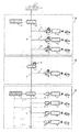
次に本発明のうち窒素インフラ部分だけを取り出して[図3]に示す。図3に示す窒素インフラは図2の水素インフラと同様、供給先をA,B,C地域へ供給するが、各々の地域により機器の構成が異なっている。 図3で構成される主な設備と機器は窒素製造所、窒素導管、水素・窒素混合器、水素・窒素分離器及び水素精製器である。 Next, only the nitrogen infrastructure part of the present invention is taken out and shown in FIG. The nitrogen infrastructure shown in FIG. 3 supplies the supply destinations to the A, B, and C regions, as in the hydrogen infrastructure of FIG. 2, but the configuration of the device differs depending on each region. The main equipment and equipment configured in FIG. 3 are a nitrogen plant, a nitrogen conduit, a hydrogen / nitrogen mixer, a hydrogen / nitrogen separator and a hydrogen purifier.
A地域は窒素製造所、窒素導管、水素・窒素混合器及び水素精製器で構成される。この地域での窒素製造所は水素製造所からの水素に出来るだけ早期に窒素を混合するため水素製造所の近傍に設置する。例えば製鉄所で発生するCOGガスからの水素を使う場合は、同じ製鉄所の酸素製鋼用に使用される酸素と共に副生する窒素を窒素製造所として活用する。 Area A consists of a nitrogen plant, a nitrogen conduit, a hydrogen / nitrogen mixer and a hydrogen purifier. A nitrogen plant in this area will be located near the hydrogen plant to mix the nitrogen from the hydrogen plant as soon as possible. For example, when using hydrogen from COG gas generated at a steelmaking plant, nitrogen by-produced together with oxygen used for oxygen steelmaking at the same steelmaking plant is utilized as a nitrogen production plant.
B地域は水素・窒素分離器、水素導管及び水素精製器で構成され、更にC地域は窒素製造所、水素・窒素混合器、窒素導管、水素精製器及び窒素リサイクル配管で構成される。この窒素インフラを前記の水素インフラに上乗せした場合の構成を[図1]に示す。図1は図2と図3で示した構想を合体したもので、本発明の構成を示す代表図である。 Area B consists of hydrogen and nitrogen separators, hydrogen pipes and hydrogen purifiers, and area C consists of nitrogen plants, hydrogen and nitrogen mixers, nitrogen pipes, hydrogen purifiers and nitrogen recycle pipes. The configuration when this nitrogen infrastructure is added to the above-mentioned hydrogen infrastructure is shown in FIG. FIG. 1 is a combination of the concepts shown in FIGS. 2 and 3, and is a representative view showing the configuration of the present invention.
最初に水素・窒素の混合ガスが送られるのはA地域である。例えばこの水素・窒素混合ガスは両ガスの混合比率はH2/N2=70/30(容量比)に調整し、同地域に存在する水素ステーションに送られる。水素ステーション内では水素精製器で窒素を完全に分離して水素を燃料電池車に充填する。分離された窒素は窒素ベント管を経て大気に放出される。 It is in area A that the mixed gas of hydrogen and nitrogen is sent first. For example, this hydrogen / nitrogen mixed gas is adjusted to the H2 / N2 = 70/30 (volume ratio) mixing ratio of the two gases and sent to a hydrogen station existing in the same area. In the hydrogen station, nitrogen is completely separated by a hydrogen purifier and hydrogen is charged into a fuel cell vehicle. The separated nitrogen is released to the atmosphere through a nitrogen vent pipe.
次いで水素・窒素の混合ガスはB地域に送られる。B地域は水素製造所と水素の主たる供給先あるC地域を結ぶ過疎地帯で、火災・爆発の発生危険度から見れば最もその発生確率が低い地帯である。ここでは先ず水素・窒素分離器を用いて混合ガス中の窒素の大部分を除去し、水素・窒素の混合比率を例えばH2/N2=90/10(容量比)に調整する。 The mixed gas of hydrogen and nitrogen is then sent to area B. Area B is a sparsely-populated area connecting the hydrogen production plant and area C, which is the main supply destination of hydrogen, and is the area with the lowest probability of occurrence from the viewpoint of the risk of fire and explosion. Here, a hydrogen / nitrogen separator is first used to remove most of nitrogen in the mixed gas, and the hydrogen / nitrogen mixture ratio is adjusted to, for example, H2 / N2 = 90/10 (volume ratio).
この組成で、同地域に散在する水素ステーションに送り、更に水素ステーション内では水素精製器で窒素を完全に分離して燃料電池車に水素を充填する。この地域で分離された窒素は窒素ベント管を経て大気に放出される。B地域で大部分の窒素を分離する理由は導管敷設費の削減と輸送コストの低減のためである。 With this composition, it is sent to a hydrogen station scattered in the same area, and in the hydrogen station, nitrogen is completely separated by a hydrogen purifier, and the fuel cell vehicle is charged with hydrogen. Nitrogen separated in this area is released to the atmosphere through a nitrogen vent pipe. The reason for separating most of the nitrogen in the B area is to reduce the cost of pipeline installation and reduce the cost of transportation.
次いで水素・窒素の混合ガスはC地域に送られる。C地域は水素の最大の消費地でかつ人口密度が最も高く、火災・爆発の発生確率の高い地域である。ここでは先ず水素・窒素混合器を用いて窒素製造所から窒素を混合ガスに混合し、水素・窒素の混合比率を例えばH2/N2=50/50(容量比)に調整し、同地域に存在する水素ステーションに送る。水素ステーションでは水素精製器を用いて窒素を完全に分離した後、水素を燃料電池車に充填する。 The mixed gas of hydrogen and nitrogen is then sent to area C. Area C is the largest consumption area of hydrogen and has the highest population density and a high probability of fires and explosions. Here, first, nitrogen is mixed with mixed gas from a nitrogen plant using a hydrogen / nitrogen mixer, and the mixing ratio of hydrogen / nitrogen is adjusted to, for example, H2 / N2 = 50/50 (volume ratio), and is present in the same area Sent to the hydrogen station. At the hydrogen station, after hydrogen is completely separated using a hydrogen purifier, hydrogen is charged into a fuel cell vehicle.
C地域で分離された窒素は他の地域と異なり、配管を通して窒素製造所へリサイクルされる。この窒素のリサイクルには通常は独立した配管を設けて輸送するが、窒素リサイクル配管の全部又は一部に二重管を用いて内管側には水素・窒素の混合ガスを外管側には窒素を流す方式としても良い。更にC地域に設置される窒素製造所には上記の水素ステーションからのリサイクル窒素を受け入れる設備の他に後述する液化窒素を受け入れる設備も設置する。 Unlike the other areas, nitrogen separated in area C is recycled to the nitrogen plant through piping. Normally, separate pipes are provided and transported for this nitrogen recycle, but a double pipe is used for all or part of the nitrogen recycle pipes, and a mixed gas of hydrogen and nitrogen is used for the inner pipe side for the outer pipe side. Alternatively, nitrogen may be flowed. In addition to the facilities for receiving recycled nitrogen from the hydrogen station described above, facilities for receiving liquefied nitrogen, which will be described later, are also installed at the nitrogen production site installed in Area C.
以上が本発明が第一の目標である「窒素インフラを水素インフラの火災・爆発事故の発生を防ぐために活用する」ことへの基本的な構成である。 実際の窒素インフラはこれ等に地域を多岐に組み合わせて構成される。その例を[図4]に示す。これ等の組み合わせは図1に示された構成を基本とするが、広域な地域に展開する際にはその組み合わせは任意で良い。例えば図4に示すようにA地域から直接C地域に供給したり、C地域を更に分割して並列又は直列に繋げて供給しても良い。 The above is the basic configuration to "utilize the nitrogen infrastructure to prevent the occurrence of fires and explosions of the hydrogen infrastructure" which is the first object of the present invention. The actual nitrogen infrastructure is constructed by combining these with various regions. An example is shown in FIG. The combination of these is based on the configuration shown in FIG. 1, but the combination may be arbitrary when developed in a wide area. For example, as shown in FIG. 4, the area A may be directly supplied to the area C, or the area C may be further divided and supplied in parallel or in series.
本発明を日本全域で行う場合、例えば、数十ケ所のオフサイト型水素製造所と数千ケ所の水素ステーションが本発明で示す水素インフラ及び窒素インフラの元で図4に示すような自由な組み合わせで結ばれる。この結果、水素及び窒素インフラを従来までに提言された手段に比べてより安全で人手を要しない方法で同時並行的に構築することが可能となる。 When the present invention is performed throughout Japan, for example, free combinations as shown in FIG. 4 under the hydrogen infrastructure and nitrogen infrastructure shown in the present invention by several tens of off-site hydrogen production stations and several thousands of hydrogen stations. Tied with As a result, it is possible to construct hydrogen and nitrogen infrastructure simultaneously and simultaneously in a safer and less laborious way compared to previously proposed measures.
更に従来までの水素インフラの実証は既述した北九州市での例に見られるようにその展開が一部の地域に限定されていた。地球温暖化防止に向けた水素インフラや窒素インフラの構築は少なくとも日本全域、更に中国、米国等の広大な国土を有する国々でも展開できる構想でなくてはならない。本発明はこの地球規模での展開の可能性を残す。 Furthermore, the development of hydrogen infrastructure in the past has been limited to a limited area, as shown in the example of Kitakyushu City described above. The construction of hydrogen and nitrogen infrastructures for the prevention of global warming must be a concept that can be developed at least throughout Japan, as well as in countries with large land areas such as China and the United States. The invention leaves this possibility for global deployment.
次に本発明で使用する水素・窒素の分離、混合、精製について補足を行う。本発明の大きな特徴は構築される水素及び窒素インフラでは水素と窒素の混合比率を任意にかつ正確に調整できることである。このためには先ず両者の混合比率を正確に測定する技術が不可欠である。 Next, supplementation is performed on separation, mixing, and purification of hydrogen and nitrogen used in the present invention. A major feature of the present invention is that in the constructed hydrogen and nitrogen infrastructure, the mixing ratio of hydrogen and nitrogen can be adjusted arbitrarily and accurately. For this purpose, first of all, a technology for accurately measuring the mixing ratio of the two is essential.
窒素ガス中の水素ガス濃度を正確に測定する方法として第一候補として選択したのは熱伝導度を利用する方法である。この測定法は水素の熱伝導度は窒素のそれに比べて1桁小さいことを利用する。幸い本発明が対象とする水素や窒素は燃料電池車向けであり、水素と窒素以外の不純物が極めて少なく純度が極めて高いので本測定法に最適である。 What is selected as the first candidate as a method of accurately measuring the hydrogen gas concentration in nitrogen gas is a method of utilizing thermal conductivity. This measurement method makes use of the fact that the thermal conductivity of hydrogen is an order of magnitude smaller than that of nitrogen. Fortunately, hydrogen and nitrogen targeted by the present invention are for fuel cell vehicles, and are extremely suitable for this measurement method because they are extremely low in impurities other than hydrogen and nitrogen and extremely high in purity.
第二候補は電気伝導度を利用する方法である。 例えばPt/WO3やSnO2の薄膜を使用した測定法は新しい水素濃度の測定として十分対応可能である。この方法は前項の方法と共通して小型でかつ自動化が易しいという特色を持つ。更に測定部に加熱部を有しないという安全面の長所を有している。The second candidate is a method using electrical conductivity. For example, a measuring method using a thin film of Pt / WO 3 or SnO 2 is sufficiently applicable as a new measurement of hydrogen concentration. This method is characterized in that it is compact and easy to automate in common with the method of the preceding paragraph. Furthermore, it has the advantage of safety because it does not have a heating part in the measurement part.
次の課題は上記に示した測定結果をどのような機種を使用して水素と窒素の分離・精製を行うかである。第一の機種は水素と窒素の分子の大きさ違いを利用した膜分離方式を使う機種である。次いでモレキュラー・シーブに代表される固体吸着物質資への吸着力の差を利用する機種がある。これ等の機種を活用したガスの分離・精製法は既に実用化されており、本発明に適用することは十分に可能である。 The next issue is what type of measurement results shown above are used to separate and purify hydrogen and nitrogen. The first model is a model using a membrane separation system that utilizes the size difference between hydrogen and nitrogen molecules. Next, there is a model that utilizes the difference in adsorption power to a solid adsorptive material as represented by molecular sieve. Gas separation and purification methods utilizing these models have already been put to practical use, and can be applied to the present invention sufficiently.
本発明ではこれ等の機器を水素・窒素混合器、水素・窒素分離器及び水素精製器に活用する。この内水素精製器は通常は水素ステーション内に設置され、その敷地面積上の制約を受けるケースが多いので小型化が容易な膜分離方式が適している。 In the present invention, these devices are used for a hydrogen / nitrogen mixer, a hydrogen / nitrogen separator and a hydrogen purifier. The internal hydrogen purifier is usually installed in a hydrogen station, and in many cases subject to restrictions on the area of the site, a membrane separation system that is easy to miniaturize is suitable.
一方で水素・窒素分離器と水素・窒素混合器は通常は水素・窒素の混合ガスの主要導管に設けられ、敷地上の制約を受ける心配は少ない。更にこれ等の機種はガス濃度の測定に加えて、正確な分離と混合操作を行うため前記の濃度の測定結果と流量計を組み合わせた比例制御を行う必要があり、本発明では「器」と表示しているが、むしろ装置に近い。この場合は設置場所の環境に併せて上記に記載した機種から適切な組み合わせを選択する。 On the other hand, hydrogen and nitrogen separators and hydrogen and nitrogen mixers are usually installed in the main line of hydrogen and nitrogen mixed gas, so there is less concern about site constraints. Furthermore, in addition to the measurement of the gas concentration, these models also need to perform proportional control combining the above measurement result of the concentration and the flow meter in order to perform accurate separation and mixing operation. It is displayed, but rather close to the device. In this case, an appropriate combination is selected from the models described above in accordance with the environment of the installation location.
次に本発明の第二の目標である「窒素インフラを建屋の防消火対策に活用する」ことについて記す。窒素は燃焼の三要素である「可燃物」「支燃性ガス」「着火源」のうち支燃性ガス(=酸素)の濃度を低減させて燃焼を食い止めることは既に記述した。ここでは本発明の窒素インフラを建屋の防消火対策に用いる具体的な方法を記す。 Next, the second goal of the present invention, "utilizing nitrogen infrastructure for fire prevention measures for buildings," will be described. It has already been described that nitrogen reduces the concentration of the support gas (= oxygen) to stop the combustion among the three components of combustion, "flammable materials", "support gas" and "ignition source". Here, a specific method of using the nitrogen infrastructure of the present invention for fireproofing measures for buildings is described.
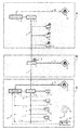
窒素インフラを建屋の防消火設備として活用する略図を[図5]に示す。この図には先の地域の区分けに従い、窒素供給設備から配管を用いて対象となる建屋に向けて窒素を供給する経路が示されている。 防消火の対象となる建屋は本文の技術背景で既に記載したように大型の物流倉庫に代表される密閉型建屋である。 A schematic diagram of using nitrogen infrastructure as fireproof and fire extinguishing equipment for buildings is shown in [Figure 5]. In this figure, a route for supplying nitrogen to a target building from a nitrogen supply facility using piping is shown in accordance with the previous regional division. The building that is the object of fire prevention and extinguishing is a closed building represented by a large-scale distribution warehouse as already described in the technical background of the text.
地域区分に従えば、A地域の窒素供給設備としては水素製造所内又は近傍の窒素製造所が挙げられる。現在、水素製造所として有望な候補は化学工場、石油化学コンビナート各社、製鉄所等があり、これ等の会社は全て自消用や保安用に十分な窒素を確保しており、供給面で不安はない。これ等の窒素供給設備から対象建屋に向けて窒素を専用配管を使用して供給圧力で1MPa以下の中圧で供給する。 According to the regional division, the nitrogen supply facility in the A region includes a nitrogen production site in or near a hydrogen production site. Currently, promising candidates for hydrogen production include chemical plants, petrochemical complex companies, and steel plants, all of which secure sufficient nitrogen for self-consumption and security use, and are concerned about supply There is no. From these nitrogen supply facilities, nitrogen is supplied to the target building at a medium pressure of 1 MPa or less at a supply pressure using dedicated piping.
B地域の窒素供給設備としては、水素・窒素の混合ガスの導管に設置される水素・窒素分離器から放出される窒素を活用する。この窒素は通常は大気中に放散されている。一般的にこの地域に存在する建屋数は他の地域に比べて少ないが、万一の緊急時には、この放散を取りやめ専用配管を用いて対象建屋へ窒素を供給する。 The nitrogen supply facility in Area B utilizes nitrogen released from the hydrogen and nitrogen separator installed in the mixed gas line of hydrogen and nitrogen. This nitrogen is usually released to the atmosphere. Generally, the number of buildings existing in this area is smaller than in other areas, but in the event of an emergency, this radiation is canceled and nitrogen is supplied to the target building using dedicated piping.
更にB地域に孤立した対象建屋が存在し、かつ水素・窒素分離器から遠距離になり配管よる窒素輸送が困難な場合は、特例として後述する液化窒素ローリ車によるバックアップ方式を採用して建屋内に直接液化窒素を吹き込むことも可能である例えばB地域に軍の基地が存在し、その敷地内にある爆薬等危険物を保管する倉庫が火災・爆発の危険に曝されたケースが、これに該当する。 Furthermore, if there is an isolated target building in area B, and it is difficult to transport nitrogen by piping because it is a long distance from the hydrogen / nitrogen separator, a backup method by liquefied nitrogen rally car described later is adopted as a special case. For example, there is a military base in area B where it is possible to blow in liquid nitrogen directly into the storage space, and in this case there is a case where the storage for storing dangerous materials such as explosives on the site is exposed to fire or explosion hazard. Applicable
C地区は他の地域に比べて圧倒的に対象とする建屋数の多い地域である。この地域の窒素供給設備としては地域内の窒素製造所が挙げられる。この窒素製造所は自ら窒素を製造する他に地域内の水素ステーションから配管を用いて窒素がリサイクルされている。 更に対象となる建屋数が多いので、 万一緊急時に窒素の供給が途絶えないよう窒素のバックアップ体制を確立しておくことが大切である。 Area C is an area where the number of buildings targeted is overwhelmingly greater than in other areas. Nitrogen supply facilities in this area include nitrogen plants in the area. In addition to producing nitrogen itself, the nitrogen plant recycles nitrogen using piping from a local hydrogen station. Furthermore, because there are many buildings to be targeted, it is important to establish a nitrogen backup system so that the supply of nitrogen will not be interrupted in the event of an emergency.
このバックアップとして[図5]に液化窒素ローリ車による供給を示す。現在都市部では病院における酸素吸入向けに専用ローリ車による液化酸素の流通が既に定着している。液化酸素は同じ地域にある空気・深冷分離装置で製造されるが、この際液化窒素が併産される。 この液化窒素を専用ローリ車を使用して窒素供給設備に運搬し、バックアップ用の窒素として活用する。 As a backup of this, Fig. 5 shows the supply by the liquefied nitrogen troll car. At present, in urban areas, the distribution of liquefied oxygen by a dedicated lorry has already been established for oxygen inhalation in hospitals. Liquefied oxygen is produced by an air / cryogenic separator located in the same area, where liquefied nitrogen is co-produced. This liquefied nitrogen is transported to a nitrogen supply facility using a dedicated rori vehicle and used as backup nitrogen.
次に専用配管を使用して供給される窒素を対象建屋において防消火設備として使用する方法について記す。窒素による窒息効果を高めるためには建屋の気密性を出来るだけ保った状態で内部に滞留する空気を吹き込んだ窒素と共に排気系に導くことが大切である。先ず本発明の効果を有効に活用させるために対象建屋本体の構造について記す。 Next, the method of using nitrogen supplied using dedicated piping as a fire extinguishing system in the target building will be described. In order to enhance the suffocating effect of nitrogen, it is important to introduce the air staying inside while keeping the airtightness of the building as much as possible to the exhaust system together with the blown nitrogen. First, in order to make effective use of the effects of the present invention, the structure of a target building body will be described.
本発明の対象となる建屋は物流倉庫に代表される大型建屋で通常は数階建て、かつ出入口を除けば開口部の少ない密閉型構造を有するものが多い。建屋の最上階には大気に通じる換気部を有するが、緊急時に吹き込むような大量の窒素を排気できる構造となってない。 The building to which the present invention is applied is a large-scale building represented by a distribution warehouse, and usually has several floors and a closed type structure with few openings except for the entrance. Although the top floor of the building has a ventilating section leading to the atmosphere, it does not have a structure capable of exhausting a large amount of nitrogen that can be blown in an emergency.
このような構造を有する建屋には通常の換気部に加えて、緊急時の大量の窒素の吹き込みに備えて臨時に使用できる排気経路を別途確保しておく必要がある。具体的にはこの経路に換気ゲートやラプチュア・デスク(=破裂板)を設けて通常は大気と遮断しておき、緊急時だけこれ等の機器を開放できる構造とすれば良い。この処置により、地上部から導入された大量の窒素は建屋内の空気と十分に混合し建屋内を加圧することなく、排気経路を経由して建屋上部から大気に放散される。 In a building having such a structure, in addition to a normal ventilation unit, it is necessary to separately secure an exhaust path that can be used temporarily in preparation for the blowing of a large amount of nitrogen in an emergency. Specifically, a ventilation gate or a rupture disk (= rupture disc) may be provided in this path to normally shut off from the atmosphere, and these devices may be opened only in the event of an emergency. By this measure, a large amount of nitrogen introduced from above the ground is sufficiently mixed with the air in the building to be released from the roof to the atmosphere via the exhaust path without pressurizing the building.
次に窒素インフラから分岐された窒素配管を対象建屋敷地で建屋の防消火設備と連結する方法について記す。[図6]には連結部の略図を示す。両配管は図6に示すように平常時には連結せず、緊急時のみ専用の連結用配管を用いて連結する。これは建屋内に人間が在室している場合、誤って窒素が導入されると酸素欠乏により重大災害が発生する恐れがあるからである。 Next, we will describe how to connect the nitrogen piping branched from the nitrogen infrastructure with the fire prevention equipment of the building at the target building site. [FIG. 6] shows a schematic view of the connection part. Both pipes are not connected normally as shown in FIG. 6, but are connected using a dedicated connection pipe only in case of emergency. This is because, if there is a human being in the building, there is a risk that a serious disaster may occur due to oxygen deficiency if nitrogen is mistakenly introduced.
この危険の防止のため、図6の上段には 緊急時に連結用配管を用いて窒素配管と連結した後、予め指定された管理者が所有する特定パスワードをパスワード入力装置に入力しない限り、窒素元弁ロック機能を解除できない防護策が示されている。図6の下段にはこの防護策に加えて「煙検知による火災発生情報」「赤外線センサーによる無人確認情報」「換気ゲート開放等の換気確認情報」を組み込み、この回路が作動しない限り同ロック機能が解除できない防護策を追加し安全面での冗長化を図っている。 In order to prevent this risk, the upper part of Fig. 6 is connected to the nitrogen piping using the connection piping in an emergency, and the nitrogen source is used unless a specific password owned by a previously designated administrator is input to the password input device. Protective measures are shown that can not release the valve lock function. In the lower part of Fig. 6, in addition to this protective measure, "fire occurrence information by smoke detection", "unmanned confirmation information by infrared sensor" and "ventilation confirmation information such as opening of ventilation gate" are incorporated. Safety measures are being added in order to add protection measures that can not be released.
窒素インフラの普及に当たっては上記のハード面の対策に加え、ソフト面でも酸素欠乏による事故や災害を防止に関し対応策を確立しておかなければならない。具体的な対応として対象となる建屋は全て所轄官庁の許認可制として、かつ建屋には酸欠防止管理者の常駐を義務付ける等の対応が考えられる。 安全を確保するために導入した窒素インフラが人命を奪う凶器となってはならない。 In the spread of nitrogen infrastructure, in addition to the above-mentioned measures on the hardware side, it is necessary to establish measures to prevent accidents and disasters due to oxygen deficiency also on the software side. As specific measures, it is considered that all the buildings to be targeted are authorized and authorized by the competent government authorities, and that the buildings are obliged to require the retention of a manager for preventing the lack of oxygen. The nitrogen infrastructure introduced to ensure safety must not be a weapon to kill lives.
本発明により導管を使用する窒素インフラが確立できれば、全国規模の燃料電池車向け水素ステーションの安全対策に寄与するだけでなく密閉型の大型建屋が火災の危険に遭遇した場合従来にない新しいタイプの防消火設備として活用できる。 If a nitrogen infrastructure using a conduit can be established according to the present invention, it will not only contribute to the safety measures of hydrogen stations for fuel cell vehicles on a national scale, but also if a large enclosed building encounters a fire risk new type of unprecedented It can be used as fire extinguishing equipment.
1 水素製造所
2 窒素製造所
3 水素・窒素混合器
4 水素・窒素分離器
5 水素精製器
6 水素ステーション
7 燃料電池車
8 水素・窒素混合ガス導管
9 窒素導管
9 窒素ベント管
10 窒素配管
11 窒素リサイクル配管
12 対象建屋
13 空気分離器
14 病院
15 液化酸素ローリ輸送
16 液化窒素ローリ輸送
17 窒素元弁ロック機能
18 (窒素元弁開閉)パスワード入力装置
19 連結用配管
20 水素導管
A 人口平均地域
B 人口過疎地域
C 人口密集地域
D 対象建屋敷地1 hydrogen plant 2 nitrogen plant 3 hydrogen and nitrogen mixer 4 hydrogen and nitrogen separator 5 hydrogen purifier 6 hydrogen station 7
更にB地区に孤立した対象建屋が存在し、かつ水素・窒素分離器から遠距離になり配管による窒素輸送が困難な場合は、特例として後述する液化窒素ローリ車によるバックアップ方式を採用して建屋内に直接液化窒素吹き込むことも可能である。例えばB地区に自衛 隊の基地が存在し、その敷地内にある爆薬等危険物を保管する倉庫が火災・爆発の危険に曝されたケースがこれに該当する。Furthermore, if there is an isolated target building in area B and it is difficult to transport nitrogen by piping because it is a long distance from the hydrogen / nitrogen separator, a backup method using a liquefied nitrogen rally car described later is adopted as a special case. It is also possible to blow liquefied nitrogen directly into the For example there is the base of the SDF in B area, the case where warehouses store exposed to the risk of fire, explosion explosives such hazardous materials in its site corresponds to this.
Claims (6)
両ガスの熱伝導度又は電気伝導度の差を利用して水素・窒素混合ガス中の水素と窒素の濃度を測定し、水素・窒素の混合比率を任意に調節できることを特徴とする請求項1に記載の窒素インフラシステム。The hydrogen and nitrogen mixers and hydrogen and nitrogen separators of the nitrogen infrastructure use the difference in the size of hydrogen molecules and nitrogen molecules, or the difference in adsorption power of hydrogen molecules and nitrogen molecules on solid adsorptive substances. In the adsorption method, when measuring the concentration of hydrogen and nitrogen in the mixed gas of hydrogen and nitrogen, the concentration of hydrogen and nitrogen in the hydrogen / nitrogen mixed gas using the difference in thermal conductivity or electric conductivity of both gases The nitrogen infrastructure system according to claim 1, wherein the mixing ratio of hydrogen and nitrogen can be arbitrarily adjusted.
Priority Applications (1)
| Application Number | Priority Date | Filing Date | Title |
|---|---|---|---|
| JP2017084042A JP6443846B2 (en) | 2017-04-05 | 2017-04-05 | Nitrogen infrastructure system |
Applications Claiming Priority (1)
| Application Number | Priority Date | Filing Date | Title |
|---|---|---|---|
| JP2017084042A JP6443846B2 (en) | 2017-04-05 | 2017-04-05 | Nitrogen infrastructure system |
Publications (2)
| Publication Number | Publication Date |
|---|---|
| JP2018175730A true JP2018175730A (en) | 2018-11-15 |
| JP6443846B2 JP6443846B2 (en) | 2018-12-26 |
Family
ID=64281882
Family Applications (1)
| Application Number | Title | Priority Date | Filing Date |
|---|---|---|---|
| JP2017084042A Active JP6443846B2 (en) | 2017-04-05 | 2017-04-05 | Nitrogen infrastructure system |
Country Status (1)
| Country | Link |
|---|---|
| JP (1) | JP6443846B2 (en) |
Cited By (2)
| Publication number | Priority date | Publication date | Assignee | Title |
|---|---|---|---|---|
| JP2022013478A (en) * | 2020-07-01 | 2022-01-18 | 淳 富永 | Fire protection facility for detached house building |
| WO2023116674A1 (en) * | 2021-12-20 | 2023-06-29 | 未势能源科技有限公司 | Liquid hydrogen filling system |
Citations (9)
| Publication number | Priority date | Publication date | Assignee | Title |
|---|---|---|---|---|
| JPS6188755U (en) * | 1985-06-03 | 1986-06-10 | ||
| JPH01239089A (en) * | 1987-11-30 | 1989-09-25 | Toshiba Corp | Process for production of compound semiconductor single crystal and apparatus therefor |
| JP2002235900A (en) * | 2001-02-13 | 2002-08-23 | Tokyo Gas Co Ltd | Hydrogen gas supplying method |
| JP2004130054A (en) * | 2002-08-09 | 2004-04-30 | Daido:Kk | Fire extinguishing gas supply system |
| JP2004146312A (en) * | 2002-08-26 | 2004-05-20 | Atsushi Tominaga | Safe supply method of hydrogen for fuel cell |
| JP2004220802A (en) * | 2003-01-09 | 2004-08-05 | Seiichi Muto | Hydrogen standard infrastructure system |
| JP2006207785A (en) * | 2005-01-24 | 2006-08-10 | Atsushi Tominaga | Hydrogen filling apparatus |
| JP2008222189A (en) * | 2007-03-08 | 2008-09-25 | Atsushi Tominaga | Nitrogen gas filling apparatus in tire |
| JP2016193810A (en) * | 2015-03-31 | 2016-11-17 | 富永 淳 | System for monitoring hydrogen leakage from conduit |
-
2017
- 2017-04-05 JP JP2017084042A patent/JP6443846B2/en active Active
Patent Citations (9)
| Publication number | Priority date | Publication date | Assignee | Title |
|---|---|---|---|---|
| JPS6188755U (en) * | 1985-06-03 | 1986-06-10 | ||
| JPH01239089A (en) * | 1987-11-30 | 1989-09-25 | Toshiba Corp | Process for production of compound semiconductor single crystal and apparatus therefor |
| JP2002235900A (en) * | 2001-02-13 | 2002-08-23 | Tokyo Gas Co Ltd | Hydrogen gas supplying method |
| JP2004130054A (en) * | 2002-08-09 | 2004-04-30 | Daido:Kk | Fire extinguishing gas supply system |
| JP2004146312A (en) * | 2002-08-26 | 2004-05-20 | Atsushi Tominaga | Safe supply method of hydrogen for fuel cell |
| JP2004220802A (en) * | 2003-01-09 | 2004-08-05 | Seiichi Muto | Hydrogen standard infrastructure system |
| JP2006207785A (en) * | 2005-01-24 | 2006-08-10 | Atsushi Tominaga | Hydrogen filling apparatus |
| JP2008222189A (en) * | 2007-03-08 | 2008-09-25 | Atsushi Tominaga | Nitrogen gas filling apparatus in tire |
| JP2016193810A (en) * | 2015-03-31 | 2016-11-17 | 富永 淳 | System for monitoring hydrogen leakage from conduit |
Cited By (3)
| Publication number | Priority date | Publication date | Assignee | Title |
|---|---|---|---|---|
| JP2022013478A (en) * | 2020-07-01 | 2022-01-18 | 淳 富永 | Fire protection facility for detached house building |
| JP7245457B2 (en) | 2020-07-01 | 2023-03-24 | 淳 富永 | Fire extinguishing equipment for detached houses |
| WO2023116674A1 (en) * | 2021-12-20 | 2023-06-29 | 未势能源科技有限公司 | Liquid hydrogen filling system |
Also Published As
| Publication number | Publication date |
|---|---|
| JP6443846B2 (en) | 2018-12-26 |
Similar Documents
| Publication | Publication Date | Title |
|---|---|---|
| Hansen | Hydrogen infrastructure—Efficient risk assessment and design optimization approach to ensure safe and practical solutions | |
| Gye et al. | Quantitative risk assessment of an urban hydrogen refueling station | |
| CA2530608C (en) | Hydrogen handling or dispensing system | |
| Pan et al. | Safety study of a wind–solar hybrid renewable hydrogen refuelling station in China | |
| Chakrabarti et al. | Applying HAZAN methodology to hazmat transportation risk assessment | |
| JP2018175730A (en) | Nitrogen infrastructure system | |
| Kim et al. | Quantitative risk assessment of a mobile hydrogen refueling station in Korea | |
| Verbecke et al. | Safety strategy for the first deployment of a hydrogen-based green public building in France | |
| Ustolin et al. | Computational fluid dynamics modeling of liquid hydrogen release and dispersion in gas refuelling stations | |
| Caliendo et al. | Hydrogen safety, state of the art, perspectives, risk assessment, and engineering solutions | |
| Kumar et al. | Hydrogen safety/standards (national and international document standards on hydrogen energy and fuel cell) | |
| Pasculescu et al. | Numerical modelling of hydrogen release and dispersion | |
| Rivkin et al. | Guide to Permitting Hydrogen Motor Fuel Dispensing Facilities | |
| Barilo | Safety considerations for hydrogen and fuel cell applications | |
| Wurster | Hydrogen safety: An overview | |
| Tuśnio et al. | Hazards and challenges of using hydrogen as motor vehicle fuel | |
| Wen et al. | Safety of cryogenic liquid hydrogen bunkering operations-The gaps between existing knowhow and industry needs | |
| Fjellgaard Mikalsen et al. | From petrol station to multifuel energy station: Changes in fire and explosion safety | |
| Bach et al. | Safe Hydrogen Installation on-board | |
| Priambodo et al. | Evaluation of accident consequences of LPG skid tank to the RSG GAS plant using ALOHA software | |
| Ehrhart et al. | Setback Distances for Liquefied Hydrogen Stations. | |
| Segal et al. | Safety considerations in the design of a gaseous hydrogen fuel supply for engine testing | |
| Hathaway et al. | Clean air program: design guidelines for bus transit systems using hydrogen as an alternative fuel | |
| Directorate | Fire protection facilities for petroleum refineries and oil/gas processing plants | |
| Chow et al. | Fire safety concerns on residential areas located adjacent to oil tanks |
Legal Events
| Date | Code | Title | Description |
|---|---|---|---|
| A521 | Request for written amendment filed |
Free format text: JAPANESE INTERMEDIATE CODE: A523 Effective date: 20171024 |
|
| A871 | Explanation of circumstances concerning accelerated examination |
Free format text: JAPANESE INTERMEDIATE CODE: A871 Effective date: 20180117 |
|
| A621 | Written request for application examination |
Free format text: JAPANESE INTERMEDIATE CODE: A621 Effective date: 20180117 |
|
| A975 | Report on accelerated examination |
Free format text: JAPANESE INTERMEDIATE CODE: A971005 Effective date: 20180403 |
|
| A131 | Notification of reasons for refusal |
Free format text: JAPANESE INTERMEDIATE CODE: A131 Effective date: 20180508 |
|
| A521 | Request for written amendment filed |
Free format text: JAPANESE INTERMEDIATE CODE: A523 Effective date: 20180604 |
|
| A131 | Notification of reasons for refusal |
Free format text: JAPANESE INTERMEDIATE CODE: A131 Effective date: 20180814 |
|
| A521 | Request for written amendment filed |
Free format text: JAPANESE INTERMEDIATE CODE: A523 Effective date: 20180817 |
|
| TRDD | Decision of grant or rejection written | ||
| A01 | Written decision to grant a patent or to grant a registration (utility model) |
Free format text: JAPANESE INTERMEDIATE CODE: A01 Effective date: 20181113 |
|
| A61 | First payment of annual fees (during grant procedure) |
Free format text: JAPANESE INTERMEDIATE CODE: A61 Effective date: 20181119 |
|
| R150 | Certificate of patent or registration of utility model |
Ref document number: 6443846 Country of ref document: JP Free format text: JAPANESE INTERMEDIATE CODE: R150 |
|
| R250 | Receipt of annual fees |
Free format text: JAPANESE INTERMEDIATE CODE: R250 |