JP2018161837A - Printing device, printing system, printing control method, and program - Google Patents
Printing device, printing system, printing control method, and program Download PDFInfo
- Publication number
- JP2018161837A JP2018161837A JP2017061144A JP2017061144A JP2018161837A JP 2018161837 A JP2018161837 A JP 2018161837A JP 2017061144 A JP2017061144 A JP 2017061144A JP 2017061144 A JP2017061144 A JP 2017061144A JP 2018161837 A JP2018161837 A JP 2018161837A
- Authority
- JP
- Japan
- Prior art keywords
- data
- printing
- print data
- resolution
- Prior art date
- Legal status (The legal status is an assumption and is not a legal conclusion. Google has not performed a legal analysis and makes no representation as to the accuracy of the status listed.)
- Pending
Links
Images


Classifications
-
- B—PERFORMING OPERATIONS; TRANSPORTING
- B41—PRINTING; LINING MACHINES; TYPEWRITERS; STAMPS
- B41J—TYPEWRITERS; SELECTIVE PRINTING MECHANISMS, i.e. MECHANISMS PRINTING OTHERWISE THAN FROM A FORME; CORRECTION OF TYPOGRAPHICAL ERRORS
- B41J2/00—Typewriters or selective printing mechanisms characterised by the printing or marking process for which they are designed
- B41J2/315—Typewriters or selective printing mechanisms characterised by the printing or marking process for which they are designed characterised by selective application of heat to a heat sensitive printing or impression-transfer material
- B41J2/32—Typewriters or selective printing mechanisms characterised by the printing or marking process for which they are designed characterised by selective application of heat to a heat sensitive printing or impression-transfer material using thermal heads
- B41J2/35—Typewriters or selective printing mechanisms characterised by the printing or marking process for which they are designed characterised by selective application of heat to a heat sensitive printing or impression-transfer material using thermal heads providing current or voltage to the thermal head
- B41J2/355—Control circuits for heating-element selection
- B41J2/3551—Block driving
-
- B—PERFORMING OPERATIONS; TRANSPORTING
- B41—PRINTING; LINING MACHINES; TYPEWRITERS; STAMPS
- B41J—TYPEWRITERS; SELECTIVE PRINTING MECHANISMS, i.e. MECHANISMS PRINTING OTHERWISE THAN FROM A FORME; CORRECTION OF TYPOGRAPHICAL ERRORS
- B41J2/00—Typewriters or selective printing mechanisms characterised by the printing or marking process for which they are designed
- B41J2/315—Typewriters or selective printing mechanisms characterised by the printing or marking process for which they are designed characterised by selective application of heat to a heat sensitive printing or impression-transfer material
- B41J2/32—Typewriters or selective printing mechanisms characterised by the printing or marking process for which they are designed characterised by selective application of heat to a heat sensitive printing or impression-transfer material using thermal heads
- B41J2/35—Typewriters or selective printing mechanisms characterised by the printing or marking process for which they are designed characterised by selective application of heat to a heat sensitive printing or impression-transfer material using thermal heads providing current or voltage to the thermal head
Abstract
Description
本明細書は、印刷装置、印刷システム、印刷制御方法、及び、プログラムに関する。 The present specification relates to a printing apparatus, a printing system, a printing control method, and a program.
従来から、印刷装置の分野では、印刷速度の高速化と印刷内容の高解像度化が望まれている。このような要望は、例えば特許文献1に記載されるような、サーマルヘッドを備える印刷装置においても同様に存在する。
Conventionally, in the field of printing apparatuses, it has been desired to increase the printing speed and to increase the resolution of printed contents. Such a demand also exists in a printing apparatus including a thermal head as described in
しかしながら、サーマルヘッドを備える印刷装置では、印刷速度の高速化に伴い1ライン分の印刷を行うための期間が短くなると、当該期間中にサーマルヘッドの冷却期間を十分に設けることができない。その結果、サーマルヘッドに熱が溜りやすくなり、細かな印刷ドットを形成することが難しくなる。 However, in a printing apparatus including a thermal head, if the period for performing printing for one line is shortened as the printing speed is increased, a sufficient cooling period for the thermal head cannot be provided during the period. As a result, heat tends to accumulate in the thermal head, and it becomes difficult to form fine print dots.
印刷データの解像度を落とすことで、1ライン分の印刷を行うための期間をより長く確保することができるが、この方法では、印刷速度の高速化と印刷内容の高解像度化を両立することは困難である。 By reducing the resolution of the print data, it is possible to secure a longer period for performing printing for one line. However, with this method, it is possible to achieve both higher printing speed and higher resolution of printing contents. Have difficulty.
以上のような実情を踏まえ、本発明の一側面に係る目的は、印刷速度の高速化と印刷内容の高解像度化を両立する技術を提供することである。 In light of the above situation, an object according to one aspect of the present invention is to provide a technique that achieves both high printing speed and high resolution of printed content.
本発明の一態様に係る印刷装置は、発熱素子を有し、前記発熱素子に通電を行うことにより被印刷媒体に印刷を行うサーマルヘッドと、制御回路と、を備える。前記制御回路は、第1解像度で形成されている元画像を前記第1解像度より低い第2解像度の第1印刷データに従って複数の印刷ドットにより印刷した場合の印刷画像において、解像度の低下によって前記印刷画像に生じる段差部分に、前記発熱素子に前記通電を行う通電時間が前記印刷ドットに設定されている通電時間を分割した複数の分割通電時間の何れかに設定されている補間ドットを印刷するための補間データを生成し、前記第1印刷データを、該第1印刷データに前記補間データを付加した第2印刷データに変換し、前記サーマルヘッドにより前記第2印刷データに従って前記印刷を行うように制御する。 A printing apparatus according to an aspect of the present invention includes a thermal head that includes a heat generating element and performs printing on a print medium by energizing the heat generating element, and a control circuit. The control circuit prints the original image formed at the first resolution with a decrease in resolution in a print image obtained by printing with a plurality of print dots according to the first print data of the second resolution lower than the first resolution. In order to print the interpolated dots set to any one of a plurality of divided energizing times obtained by dividing the energizing time set for the print dots on the stepped portion generated in the image. Interpolation data is generated, the first print data is converted to second print data obtained by adding the interpolation data to the first print data, and the printing is performed according to the second print data by the thermal head. Control.
本発明の一態様に係る印刷システムは、印刷装置と印刷制御装置とを備える印刷システムであって、前記印刷装置は、発熱素子を有し、前記発熱素子に通電を行うことにより被印刷媒体に印刷を行うサーマルヘッドと、制御回路と、を備える。前記印刷制御装置は、第1解像度で形成されている元画像を前記第1解像度より低い第2解像度の第1印刷データに従って複数の印刷ドットにより印刷した場合の印刷画像において、解像度の低下によって前記印刷画像に生じる段差部分に、前記発熱素子に前記通電を行う通電時間が前記印刷ドットに設定されている通電時間を分割した複数の分割通電時間の何れかに設定されている補間ドットを印刷するための補間データを生成し、前記第1印刷データを、該第1印刷データに前記補間データを付加した第2印刷データに変換し、前記第2印刷データを前記印刷装置へ出力する。前記制御回路は、前記サーマルヘッドにより前記第2印刷データに従って前記印刷を行うように制御する。 The printing system which concerns on 1 aspect of this invention is a printing system provided with a printing apparatus and a printing control apparatus, Comprising: The said printing apparatus has a heat generating element, and it supplies to a printing medium by energizing the said heat generating element. A thermal head for performing printing and a control circuit are provided. The print control apparatus is configured to print the original image formed at the first resolution with a plurality of print dots according to the first print data at the second resolution lower than the first resolution, and the print control device causes the reduction in resolution. Interpolation dots set to any one of a plurality of divided energizing times obtained by dividing the energizing time set for the print dots are printed on the stepped portion of the printed image. Interpolation data is generated, the first print data is converted into second print data obtained by adding the interpolation data to the first print data, and the second print data is output to the printing apparatus. The control circuit controls the thermal head to perform the printing according to the second print data.
本発明の一態様に係る印刷制御方法は、第1解像度で形成されている元画像を前記第1解像度より低い第2解像度の第1印刷データに従って複数の印刷ドットにより印刷した場合の印刷画像において、解像度の低下によって前記印刷画像に生じる段差部分に、サーマルヘッドの発熱素子に通電を行う通電時間が前記印刷ドットに設定されている通電時間を分割した複数の分割通電時間の何れかに設定されている補間ドットを印刷するための補間データを生成し、前記第1印刷データを、該第1印刷データに前記補間データを付加した第2印刷データに変換し、前記第2印刷データに従って前記発熱素子に通電を行うことにより被印刷媒体に印刷を行うように、前記サーマルヘッドを制御する。 A print control method according to an aspect of the present invention provides a print image when an original image formed at a first resolution is printed with a plurality of print dots in accordance with first print data at a second resolution lower than the first resolution. The energizing time for energizing the heat generating elements of the thermal head is set to any one of a plurality of divided energizing times obtained by dividing the energizing time set for the print dots at the step portion generated in the printed image due to the decrease in resolution. Generating interpolation data for printing the interpolated dots, converting the first print data into second print data obtained by adding the interpolation data to the first print data, and generating the heat according to the second print data The thermal head is controlled so that printing is performed on a printing medium by energizing the element.
本発明の一態様に係るプログラムは、サーマルヘッドを有する印刷装置が備えるコンピュータに、第1解像度で形成されている元画像を前記第1解像度より低い第2解像度の第1印刷データに従って複数の印刷ドットにより印刷した場合の印刷画像において、解像度の低下によって前記印刷画像に生じる段差部分に、前記サーマルヘッドの発熱素子に通電を行う通電時間が前記印刷ドットに設定されている通電時間を分割した複数の分割通電時間の何れかに設定されている補間ドットを印刷するための補間データを生成し、前記第1印刷データを、該第1印刷データに前記補間データを付加した第2印刷データに変換し、前記第2印刷データに従って前記発熱素子に通電を行うことにより被印刷媒体に印刷を行うように、前記サーマルヘッドを制御する処理を実行させる。 According to one aspect of the present invention, a program included in a printing apparatus having a thermal head prints a plurality of original images formed at a first resolution according to first print data at a second resolution lower than the first resolution. In the printed image when printed with dots, the energizing time for energizing the heating element of the thermal head is divided into the energizing time set for the printing dots at the stepped portion generated in the printed image due to a decrease in resolution. Interpolation data for printing interpolation dots set in any of the divided energization times is generated, and the first print data is converted into second print data obtained by adding the interpolation data to the first print data The thermal head is configured to perform printing on a printing medium by energizing the heating element according to the second print data. To execute a process of controlling.
上記の態様によれば、印刷速度の高速化と印刷内容の高解像度化を両立することができる。 According to the above aspect, it is possible to achieve both higher printing speed and higher resolution of the printing content.
[第1の実施形態]
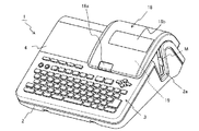
図1は、第1の実施形態に係る印刷装置1の斜視図である。印刷装置1は、被印刷媒体に印刷を行うサーマルヘッドを備える印刷装置であり、例えば、長尺状の被印刷媒体Mに、シングルパス方式で印刷を行うラベルプリンタである。以降では、インクリボンを使用する熱転写方式のラベルプリンタを例にして説明するが、印刷方式は特に限定されない。例えば、感熱紙を使用する感熱方式であってもよい。被印刷媒体Mは、例えば、接着層を有する基材と、接着層を覆うように剥離可能に基材に貼付された剥離紙と、を有するテープ部材である。被印刷媒体Mは、離型紙なしのテープ部材であってもよい。
[First Embodiment]
FIG. 1 is a perspective view of a
印刷装置1は、図1に示すように、装置筐体2と、入力部3と、表示部4と、開閉蓋18と、カセット収納部19を備える。装置筐体2の上面には、入力部3、表示部4、及び開閉蓋18が配置されている。また、図示しないが、装置筐体2には、電源コード接続端子、外部機器接続端子、記憶媒体挿入口等が設けられている。
As shown in FIG. 1, the
入力部3は、入力キー、十字キー、変換キー、決定キーなどの種々のキーを備える。表示部4は、例えば液晶表示パネルであり、入力部3からの入力に対応する文字等、各種設定のための選択メニュー、各種処理に関するメッセージ等を表示する。また、印刷中には、被印刷媒体Mへの印刷が指示された文字や図形等の内容(以降、印刷内容と記す)が表示され、印刷処理の進捗状況が表示されてもよい。なお、表示部4にはタッチパネルユニットが設けられていてもよく、その場合、表示部4を入力部3の一部として看做してもよい。また、表示部4は、印刷装置1の異常が検知されたときに所定のメッセージを表示して、印刷装置1の異常を利用者に報知してもよい。即ち、表示部4は、印刷装置1の異常を報知する報知部である。
The
開閉蓋18は、カセット収納部19の上部に開閉可能に配置されている。開閉蓋18は、ボタン18aを押下されることにより開放される。開閉蓋18には、この開閉蓋18が閉じた状態でもカセット収納部19にテープカセット30(図2参照)が収納されているか否かを目視で確認可能とするために、窓18bが形成されている。また、装置筐体2の側面には、排出口2aが形成されている。印刷装置1内で印刷が行われた被印刷媒体Mは、排出口2aから装置外へ排出される。
The opening / closing
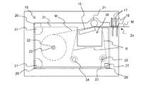
図2は、印刷装置1に収納されるテープカセット30の斜視図である。図3は、印刷装置1のカセット収納部19の斜視図である。図4は、印刷装置1の断面図である。図2に示すテープカセット30は、図3に示すカセット収納部19に着脱自在に収納される。図4には、テープカセット30がカセット収納部19に収納された状態が示されている。
FIG. 2 is a perspective view of the
テープカセット30は、図2に示すように、サーマルヘッド被挿入部36及び係合部37が形成された、被印刷媒体MとインクリボンRを収容するカセットケース31を有する。カセットケース31には、テープコア32とインクリボン供給コア34とインクリボン巻取りコア35が設けられている。被印刷媒体Mは、カセットケース31内部のテープコア32にロール状に巻かれている。また、熱転写用のインクリボンRは、その先端がインクリボン巻取りコア35に巻きつけられた状態で、カセットケース31内部のインクリボン供給コア34にロール状に巻かれている。
As shown in FIG. 2, the
装置筐体2のカセット収納部19には、図3に示すように、テープカセット30を所定の位置で支持するための複数のカセット受け部20が設けられている。また、カセット受け部20には、テープカセット30が収容するテープ(被印刷媒体M)の幅を検出するためのテープ幅検出スイッチ24が設けられている。テープ幅検出スイッチ24は、カセットの形状に基づいて被印刷媒体Mの幅を検出する幅検出部である。
As shown in FIG. 3, the
カセット収納部19には、さらに、複数の発熱素子を有し、被印刷媒体Mに印刷を行うサーマルヘッド10と、被印刷媒体Mを搬送する搬送部であるプラテンローラ21と、テープコア係合軸22と、インクリボン巻取り駆動軸23が設けられている。さらに、サーマルヘッド10には、サーミスタ13が埋め込まれている。サーミスタ13は、サーマルヘッド10の温度を測定するヘッド温度測定部である。
The
テープカセット30がカセット収納部19に収納された状態では、図4に示すように、カセットケース31に設けられた係合部37がカセット収納部19に設けられたカセット受け部20に支持されて、サーマルヘッド10がカセットケース31に形成されたサーマルヘッド被挿入部36に挿入される。また、テープコア係合軸22には、テープカセット30のテープコア32が係合し、さらに、インクリボン巻取り駆動軸23には、インクリボン巻取りコア35が係合する。
In the state in which the
印刷装置1に印刷指示が入力されると、被印刷媒体Mは、プラテンローラ21の回転によりテープコア32から繰り出される。この際、インクリボン巻取り駆動軸23がプラテンローラ21に同調して回転することで、被印刷媒体MとともにインクリボンRがインクリボン供給コア34から繰り出される。これにより、被印刷媒体MとインクリボンRは重なった状態で搬送される。そして、サーマルヘッド10とプラテンローラ21の間を通過する際にインクリボンRがサーマルヘッド10によって加熱されることで、インクが被印刷媒体Mに転写され、印刷が行われる。
When a printing instruction is input to the
サーマルヘッド10とプラテンローラ21の間を通過した使用済みのインクリボンRは、インクリボン巻取りコア35に巻き取られる。一方、サーマルヘッド10とプラテンローラ21の間を通過した印刷済みの被印刷媒体Mは、ハーフカット機構16及びフルカット機構17で切断され、排出口2aから排出される。
The used ink ribbon R that has passed between the
図5は、印刷装置1のハードウェア構成を示したブロック図である。印刷装置1は、上述の入力部3、表示部4、サーマルヘッド10、サーミスタ13、ハーフカット機構16、フルカット機構17、プラテンローラ21、テープ幅検出スイッチ24に加えて、制御回路5、ROM(Read Only Memory)6、RAM(Random Access Memory)7、表示部駆動回路8、ヘッド駆動回路9、搬送用モータ駆動回路11、ステッピングモータ12、カッターモータ駆動回路14、カッターモータ15、及び、電源回路40を備える。なお、少なくとも制御回路5、ROM6、及びRAM7は、印刷装置1のコンピュータを構成する。
FIG. 5 is a block diagram illustrating a hardware configuration of the
制御回路5は、例えばCPU(Central Processing Unit)などのプロセッサ5aを含む。制御回路5は、ROM6に記憶されているプログラムをRAM7に展開し実行することで、印刷装置1の各部の動作を制御する。
The
制御回路5は、例えば、制御信号(ストローブ信号、ラッチ信号、クロック信号)と印刷データをヘッド駆動回路9へ供給し、ヘッド駆動回路9を介してサーマルヘッド10を制御する。また、制御回路5は、モータ駆動回路(搬送用モータ駆動回路11、カッターモータ駆動回路14)を介してモータ(ステッピングモータ12、カッターモータ15)を制御する。
For example, the
ROM6は、被印刷媒体Mに印刷を行う印刷プログラム、印刷プログラムの実行に必要な各種データ(例えば、フォント、通電テーブル等)を記憶する。ROM6は、制御回路5によって読取り可能なプログラムが記憶された記憶媒体としても機能する。RAM7は、印刷内容のパターンを示すデータ(以降、印刷データと記す)を記憶する印刷データ記憶部を含む。さらに、RAM7は、表示データを記憶する表示データ記憶部を含む。
The ROM 6 stores a printing program for printing on the printing medium M and various data (for example, fonts, energization tables, etc.) necessary for executing the printing program. The ROM 6 also functions as a storage medium in which a program readable by the
表示部駆動回路8は、RAM7に記憶された表示データに基づいて表示部4を制御する。表示部4は、表示部駆動回路8の制御下で、例えば、印刷処理の進捗状況が認識可能な態様で印刷内容を表示してもよい。
The display unit drive circuit 8 controls the
ヘッド駆動回路9は、制御回路5から供給された制御信号と印刷データに基づいてサーマルヘッド10を駆動するヘッド駆動部であり、印刷データを保持するラッチ回路9aを備えている。より詳細には、ヘッド駆動回路9は、ストローブ信号がONである通電期間中に、ラッチ回路9aから出力された印刷データに基づいて複数の発熱素子10aに対して電圧の通電又は非通電を制御する。
The head drive circuit 9 is a head drive unit that drives the
サーマルヘッド10は、主走査方向に配列された複数の発熱素子10aを有する印刷ヘッドである。ヘッド駆動回路9が、制御回路5から供給されたストローブ信号により指定される通電期間中に、ラッチ回路9aから出力された印刷データに応じて発熱素子10aへ電流を選択的に流すことで、発熱素子10aが発熱してインクリボンRを加熱する。これにより、サーマルヘッド10は、熱転写により被印刷媒体Mに1ラインずつ印刷を行う。即ち、印刷装置1は、サーマルラインプリンタである。
The
搬送用モータ駆動回路11は、ステッピングモータ12を駆動する。ステッピングモータ12は、プラテンローラ21を回転させる。プラテンローラ21は、ステッピングモータ12の動力によって回転し、被印刷媒体Mの長手方向(副走査方向)に被印刷媒体Mを搬送する搬送部である。
The conveyance motor drive circuit 11 drives the stepping
カッターモータ駆動回路14は、カッターモータ15を駆動する。ハーフカット機構16及びフルカット機構17は、カッターモータ15の動力によって動作し、被印刷媒体Mをハーフカット又はフルカットする。フルカットとは、被印刷媒体Mの基材を剥離紙とともに幅方向に沿って切断する動作のことであり、ハーフカットは、基材のみを幅方向に沿って切断する動作のことである。
The cutter
電源回路40は、ACアダプタ50からの直流電圧(例えば、24V)から出力電圧を生成し、印刷装置1の各部に電力を供給する電源部である。
The
図6は、印刷装置1の機能構成を示したブロック図である。図7は、ヘッド駆動回路9に入力される信号のタイミングチャートである。図6には、主に、印刷装置1に含まれる制御回路5の機能構成が示されている。制御回路5は、データ変換部60と、ヘッド制御回路70を備えている。データ変換部60、ヘッド制御回路70は、それぞれ専用の回路で構成されていてもよく、また、ROM6に格納されているプログラムをプロセッサ5aが実行することにより実現されてもよい。
FIG. 6 is a block diagram illustrating a functional configuration of the
データ変換部60は、印刷内容を示す印刷データ(以降、第1印刷データと記す)を第1印刷データよりも被印刷媒体Mの搬送方向に高い解像度を有する印刷データ(以降、第2印刷データと記す)であって、第1印刷データが示す段差部分が補間された第2印刷データに変換する。データ変換部60で使用される第1印刷データは、RAM7の印刷データ記憶部7aから読み出される。ここで、“段差部分”とは、互いに隣接する2つのライン間に生じる1つの印刷ドット分の段差のことであり、“段差部分が補間された”とは、段差部分の一部にデータが追加されて段差が滑らかにされたことをいう。
The
具体的には、データ変換部60は、第1印刷データから分割データと補間データを生成し、少なくとも分割データと補間データに基づいて第2印刷データを生成する。例えば、分割データと補間データが2値データであれば、分割データと補間データの論理和をドット単位で得ることにより第2印刷データを生成してもよい。また、データ変換部60は、第1印刷データから分割データと補間データと予備加熱データを生成し、分割データと補間データと予備加熱データに基づいて第2印刷データを生成してもよい。例えば、分割データと補間データの論理和をドット単位で得ることにより本加熱データを生成し、本加熱データと予備加熱データに基づいて第2印刷データを生成しても良い。データ変換部60で生成された第2印刷データは、印刷データ記憶部7aに格納されても良く、ヘッド制御回路70へ出力されてもよい。なお、分割データ、補間データ、予備加熱データについては後述する。
Specifically, the
より具体的には、データ変換部60は、分割データ生成部61と、補間データ生成部62と、予備加熱データ生成部63を備える。
More specifically, the
分割データ生成部61は、第1印刷データに含まれる複数のドットデータの各々における通電時間を複数の分割通電時間に分割して、分割後のドットデータを含む分割データを生成する。これにより、例えば、通電時間を2分割した場合であれば、2つの分割通電時間はそれぞれ通電時間の半分の時間となり、分割データにおいては、搬送方向についての情報量が2倍になる。
The divided
補間データ生成部62は、第1印刷データに基づいて、分割データに対応する解像度を有する補間データであって、第1印刷データが示す印刷内容における1つの印刷ドット分の段差部分を補間する補間データを生成する。これにより、データが示す印刷内容の解像度をデータの解像度と実質的に同じにすることができる。ここで、“第1印刷データに基づいて生成する”とは、第1印刷データに直接的に基づいて生成する場合の他、例えば、第1印刷データから生成された分割データに基づいて生成する、即ち、第1印刷データに間接的に基づいて生成する場合も含む。
The interpolation
具体的には、補間データ生成部62は、まず、第1印刷データに基づいて段差部分を特定し、その後、特定された段差部分の一部に付加する補間データを生成する。
Specifically, the interpolation
段差部分の特定方法は特に限定しないが、例えば、第1印刷データが示す各ドットとその周囲の8ドットの状態(例えば、ON/OFF、“1”/“0”)に基づいて、各ドットが1つの印刷ドット分の段差部分に該当するか否かを判定してもよい。より具体的には、各ドットとその周囲の8ドットが形成するパターンが予め段差部分に該当するパターンとして登録されたパターン(例えば、L字パターン)に一致するか否かに基づいて判定してもよい。 The method for identifying the stepped portion is not particularly limited. For example, each dot is determined based on each dot indicated by the first print data and the surrounding eight dots (for example, ON / OFF, “1” / “0”). It may be determined whether or not corresponds to a step portion for one print dot. More specifically, a determination is made based on whether or not the pattern formed by each dot and the surrounding 8 dots matches a pattern (for example, an L-shaped pattern) registered in advance as a pattern corresponding to the stepped portion. Also good.
予備加熱データ生成部63は、第1印刷データに基づいて、予備加熱データを生成する。予備加熱とは、被印刷媒体Mに印刷ドットを形成する前に、印刷ドットが形成されない程度にサーマルヘッド10を予備的に加熱して温めることをいい、主にスティッキングの発生を抑制するために行われる。予備加熱データとは、予備加熱をドット単位で選択的に行うためのデータであり、第1印刷データに対応する解像度を有している。
The preliminary heating data generation unit 63 generates preliminary heating data based on the first print data. Preheating refers to preheating and heating the
具体的には、予備加熱データ生成部63は、全ドットがON状態を有するように予備加熱データを生成してもよい。この場合、予備加熱データを容易に生成することができる。また、予備加熱データ生成部63は、印刷ドットが形成されるドット近傍でのみON状態を有するように予備加熱データを生成してもよい。この場合、サーマルヘッド10の無駄な加熱を回避して、消費電力を抑えることができる。
Specifically, the preheating data generation unit 63 may generate preheating data so that all dots have an ON state. In this case, preheating data can be easily generated. Further, the preheating data generation unit 63 may generate the preheating data so as to have an ON state only in the vicinity of the dots where the printing dots are formed. In this case, useless heating of the
ヘッド制御回路70は、少なくとも、ストローブ信号とラッチ信号と第2印刷データをヘッド駆動回路9へ出力する。ストローブ信号は、サーマルヘッド10の発熱素子10aに電圧を印加する通電期間を指定する第1制御信号である。ラッチ信号は、ラッチ回路9aに保持されるデータの切り替えを指示する第2制御信号である。なお、ヘッド制御回路70は、さらに、クロック信号などをヘッド駆動回路9へ出力してもよい。
The
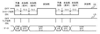
具体的には、ヘッド制御回路70は、ROM6の通電テーブル記憶部6aから読み出した通電時間データとサーミスタ13で測定したヘッド温度に基づいて通電期間の時間(予備加熱用の通電時間、本加熱用の通電時間)を算出する。そして、通電時間に応じたストローブ信号をヘッド駆動回路9へ出力する。例えば、予備加熱用の通電時間が時間T1であり、本加熱用の通電時間が時間T2であれば、ヘッド制御回路70は、図7に示すように、T1+T2の長さの通電期間を指定するストローブ信号SSを生成し、ヘッド駆動回路9へ出力する。
Specifically, the
また、ヘッド制御回路70は、予備加熱用の通電期間開始時と、本加熱用の通電期間開始時と、本加熱用の通電期間の途中に、ラッチ回路9aに保持されるデータの切り替えを指示するラッチ信号を出力する。例えば、分割データ生成部61での分割数が2の場合であれば、ヘッド制御回路70は、図7に示すように、データの切り替えを予備加熱用の通電期間開始時と本加熱用の通電期間開始時と本加熱用の通電期間の半分が経過した時に指示するラッチ信号LSを生成し、ヘッド駆動回路9へ出力する。
Further, the
これにより、ヘッド駆動回路9では、通電期間の開始から所定期間(予備加熱用の通電期間)中、ラッチ回路9aが予備加熱データをヘッド駆動回路9のドライバICへ出力し、発熱素子10aが予備加熱データに従って選択的に加熱される。また、本加熱用の通電期間中に、ラッチ回路9aが本加熱データをヘッド駆動回路9のドライバICへ出力し、発熱素子10aが本加熱データに従って選択的に加熱される。より詳細には、ラッチ回路9aが第1印刷データの単一のドットデータに対応する第2印刷データの複数のドットデータを、本加熱用の通電期間中にラッチ信号に従って順次出力する。
As a result, in the head drive circuit 9, the
以上のように構成された印刷装置1によれば、第1印刷データよりも高い解像度を有し且つ段差部分が補間された第2印刷データが示す印刷内容を、被印刷媒体Mに印刷することができる。従って、第1印刷データに基づいて印刷を行う場合と比較して、印刷速度を低下させることなく段差を滑らかに表現することが可能であり、印刷速度の高速化と印刷内容の高解像度化を両立することができる。
According to the
図8は、印刷処理のフローチャートである。図9は、データ変換処理のフローチャートである。図10は、分割データの生成方法について説明するための図である。図11は、補間データの生成方法について説明するための図である。図12は、ライン印刷処理のフローチャートである。以下、図8から図12を参照しながら、印刷装置1が行う印刷処理について具体的に説明する。
FIG. 8 is a flowchart of the printing process. FIG. 9 is a flowchart of data conversion processing. FIG. 10 is a diagram for explaining a method of generating divided data. FIG. 11 is a diagram for explaining a method of generating interpolation data. FIG. 12 is a flowchart of the line printing process. Hereinafter, the printing process performed by the
印刷装置1は、図8に示す印刷処理が開始されると、まず、図9に示すデータ変換処理を行い(ステップS100)、その後、図12に示すライン印刷処理を行う(ステップS200)。なお、データ変換処理はデータ変換部60により行われ、ライン印刷処理はヘッド制御回路70により行われる。
When the printing process shown in FIG. 8 is started, the
データ変換処理では、図9に示すように、データ変換部60は、まず、第1印刷データに基づいて分割データを生成する(ステップS101)。ここでは、分割データ生成部61は、第1印刷データに含まれる複数のドットデータの各々を搬送方向に沿って、例えば2分割して、分割データを生成する。これにより、例えば、第1印刷データが(縦、横)=(400dpi×200dpi)のデータの場合であれば、(400dpi×400dpi)の分割データが生成される。
In the data conversion process, as shown in FIG. 9, the
図10には、分割処理前後の印刷データの内容が描かれている。図10(a)には、印刷したい画像(以下、元画像とする)が、比較的高い第1解像度で形成されていて、その元画像の一部の縁がBで示す右下がりに傾斜した形状であるときに、この元画像を第1解像度より低い第2解像度の第1印刷データに従って印刷した場合の画像(以下、印刷画像とする)に形成される、元画像の縁Bに対応する印刷画像の縁の部分が輪郭線OL1で示す形状になった場合を示している。すなわち、印刷画像として、第1印刷データが示すラインL1〜ラインL4による印刷内容PC1が描かれていて、複数の印刷ドットd1の各々は、それぞれ第1印刷データに含まれる複数のドットデータのうちON状態のデータの各々に対応している。この場合、図10(a)に示すように、第1印刷データの第2解像度が元画像における第1解像度より低いことに起因して、輪郭線OL1に、元画像には存在しない段差f1、f2、f3が形成されている。すなわち、これらの段差f1、f2、f3は元画像の第1解像度に対して第1印刷データの第2解像度が低いことによる解像度の差によって生じているものであり、元画像には存在しないものであるから、段差を滑らかにするように補間すべきものである。一方、元画像と印刷画像の両方に同じ位置に存在している段差は、解像度の差によって生じているものではなく、その段差は補間すべき段差ではないことになる。本発明において行う補間データによる補間処理はこの補間すべき段差に対して行うものである。また、図10(b)には、分割データが示す印刷内容PC2が描かれていて、複数の分割ドットd2の各々は、それぞれ分割データに含まれる複数のドットデータのうちのON状態のデータの各々に対応している。なお、図示しないが、第1印刷データ及び分割データには、OFF状態のドットデータも含まれている。また、図10(b)では、分割データとの対応を明確にするため、1ライン内に搬送方向に沿って2つの分割ドットd2が形成されている例を示しているが、実際には、2つの分割ドットd2が連続して形成された結果として1つの印刷ドットd1が形成される。 FIG. 10 shows the contents of the print data before and after the division process. In FIG. 10A, an image to be printed (hereinafter referred to as an original image) is formed at a relatively high first resolution, and a part of the edge of the original image is inclined downwardly to the right indicated by B. When the image has a shape, the original image corresponds to the edge B of the original image formed in an image (hereinafter referred to as a print image) when printed according to the first print data having the second resolution lower than the first resolution. The case where the edge portion of the printed image has the shape indicated by the contour line OL1 is shown. That is, as the print image, the print content PC1 by the lines L1 to L4 indicated by the first print data is drawn, and each of the plurality of print dots d1 is a plurality of dot data included in the first print data. It corresponds to each of the data of ON state. In this case, as shown in FIG. 10A, due to the fact that the second resolution of the first print data is lower than the first resolution in the original image, a step f1, which does not exist in the original image, appears on the contour OL1. f2 and f3 are formed. That is, these steps f1, f2, and f3 are caused by the difference in resolution due to the second resolution of the first print data being lower than the first resolution of the original image, and are not present in the original image. Therefore, it should be interpolated to smooth the step. On the other hand, a step present at the same position in both the original image and the print image is not caused by a difference in resolution, and the step is not a step to be interpolated. The interpolation process using the interpolation data performed in the present invention is performed for the step to be interpolated. In FIG. 10B, the print content PC2 indicated by the divided data is drawn, and each of the plurality of divided dots d2 is an ON state data of the plurality of dot data included in the divided data. It corresponds to each. Although not shown, the first print data and the divided data include dot data in an OFF state. FIG. 10B shows an example in which two divided dots d2 are formed along the transport direction in one line in order to clarify the correspondence with the divided data. As a result of the continuous formation of the two divided dots d2, one printed dot d1 is formed.
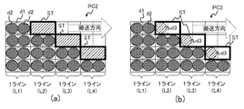
次に、データ変換部60は、補間データを生成する(ステップS102)。ここでは、補間データ生成部62は、第1印刷データに基づいて、分割データに対応する解像度を有する補間データであって、第1印刷データが示す補間すべき段差部分を補間する補間データを生成する。即ち、分割データが(400dpi×400dpi)のデータの場合であれば、補間データも(400dpi×400dpi)のデータである。
Next, the
より具体的には、補間データ生成部62は、第1印刷データに基づいて、補間すべき段差部分を特定し、特定された段差部分を補間するために段差部分の一部に付加する補間データを生成する。図11(a)には、補間データ生成部62によって特定された段差部分STが示されている。図11(b)には、分割データと補間データが示す印刷内容PC3が描かれていて、補間ドットd3の各々は、それぞれ補間データに含まれる複数のドットデータのうちのON状態のデータの各々に対応している。図11(b)では、補間ドットd3は、段差部分STのうち段差を構成する互いに隣接する2つのラインの2つの分割ドットd2に接する部分に設けられている。
More specifically, the interpolation
さらに、データ変換部60は、予備加熱データを生成する(ステップS103)。ここでは、予備加熱データ生成部63は、第1印刷データに基づいて、第1印刷データに対応する解像度を有する予備加熱データを生成する。即ち、第1印刷データが(400dpi×200dpi)のデータの場合であれば、予備加熱データも(400dpi×200dpi)のデータである。
Furthermore, the
最後に、データ変換部60は、ステップS101からステップS103で生成された、分割データ、補間データ、及び、予備加熱データに基づいて、第2印刷データを生成する(ステップS104)。なお、ステップS101からステップS103の処理は任意の順番で行われてもよく、また、時間的に並列に処理されてもよい。生成された第2印刷データは、印刷データ記憶部7aに格納される。
Finally, the
図9に示すデータ変換処理が終了すると、ヘッド制御回路70は、図12に示すライン印刷処理を開始する。ヘッド制御回路70は、まず、サーミスタ13から出力されるサーマルヘッド10のヘッド温度のデータを取得する(ステップS201)。
When the data conversion process shown in FIG. 9 is completed, the
次に、ヘッド制御回路70は、ROM6の通電テーブル記憶部6aから通電時間を取得する(ステップS202)。ここでは、ヘッド制御回路70は、通電テーブル記憶部6aに格納されている通電テーブルを参照して、ヘッド温度に応じた通電時間(予備加熱時間、本加熱時間)を取得する。
Next, the
通電時間を取得すると、ヘッド制御回路70は、RAM7の印刷データ記憶部7aから第2印刷データを1ライン分取得する(ステップS203)。なお、以降では、1ライン分の第2印刷データを第2印刷ラインデータと記す。
When the energization time is acquired, the
その後、ヘッド制御回路70は、第2印刷ラインデータと第1制御信号であるストローブ信号と第2制御信号であるラッチ信号をヘッド駆動回路9へ出力する(ステップS204)。ここでは、ヘッド制御回路70は、ステップS202で取得した通電時間(予備加熱用の通電時間、本加熱用の通電時間)に応じたストローブ信号を生成し、ヘッド駆動回路9へ出力する。また、予備加熱用の通電期間開始時と、本加熱用の通電期間開始時と、本加熱用の通電期間の途中に、ラッチ回路9aに保持されるデータの切り替えを指示するラッチ信号を出力する。さらに、ラッチ信号に合わせて第2印刷ラインデータに含まれる予備加熱データと本加熱データを順次出力する。
Thereafter, the
これにより、ヘッド駆動回路9が第2印刷ラインデータと制御信号(ストローブ信号、ラッチ信号)に基づいてサーマルヘッド10を駆動し、サーマルヘッド10により被印刷媒体Mに1ライン分の印刷が行われる。
As a result, the head drive circuit 9 drives the
最後に、ヘッド制御回路70は、ステップS203で取得した第2印刷ラインデータが最終ラインのデータか否かを判定し(ステップS205)、最終ラインのデータであればライン印刷処理を終了する。一方、最終ラインのデータでなければ、ステップS205で最終ラインであると判定されるまで、ステップS201からS205を繰り返す。
Finally, the
図13から図16は、印刷装置1による印刷例を示した図である。図13及び図14は、ラインL1〜L4において、印刷が進むにつれて、ライン毎に印刷内容の画像の上端又は下端の印刷範囲が1ドットずつ狭くなる例であり、図13と図14では、段差の向きが異なっている。図15及び図16は、ラインL1〜L4において、印刷が進むにつれてライン毎に印刷内容の画像の上端又は下端の印刷範囲が1ドットずつ広くなる例であり、図15と図16では、段差の向きが異なっている。
FIGS. 13 to 16 are diagrams illustrating examples of printing by the
印刷装置1では、図13(a)の印刷内容PC11を示す第1印刷データから、図13(b)の印刷内容PC12を示す分割データが生成される。さらに、分割データに段差部分を補間する補間データが追加されて、図13(c)の印刷内容PC13を示す第2印刷データが生成される。そして、第2印刷データに基づいて印刷が行われる。
In the
その際、図13(c)に示す補間ドットd3では、本加熱期間の一部(ここでは、後半期間)でのみ、発熱素子10aが加熱される。この期間に発熱素子10aからインクリボンRに加えられる熱量は、単独ではインクリボンRのインクを溶解又は昇華させるに至らず、補間ドットd3の周囲の印刷ドットd1を形成するために加えられた熱量の一部が流入することでかろうじてインクを溶解又は昇華させる程度のものである。このため、図13(d)に示すように、補間ドットd3のうち3つの印刷ドットd1に近接した部分にのみインクが薄く付着し、微小ドットd4が形成される。これにより、印刷内容PC11の輪郭線OL1よりも小さな段差で構成された輪郭線OL2を有する印刷結果PR13を得ることができる。 At that time, with the interpolation dot d3 shown in FIG. 13C, the heating element 10a is heated only during a part of the main heating period (here, the latter half period). The amount of heat applied from the heating element 10a to the ink ribbon R during this period does not lead to melting or sublimation of the ink on the ink ribbon R alone, but is the amount of heat applied to form the print dot d1 around the interpolation dot d3. The ink is barely dissolved or sublimated when a part of the ink flows in. For this reason, as shown in FIG. 13D, the ink is thinly attached only to the portion of the interpolation dot d3 that is close to the three printing dots d1, and the minute dot d4 is formed. As a result, it is possible to obtain a printing result PR13 having an outline OL2 configured with a step smaller than the outline OL1 of the print content PC11.
なお、図14から図16でも同様の結果が示されている。即ち、第1印刷データが示す印刷内容(PC21、PC31、PC41)の輪郭線OL1よりも小さな段差で構成された輪郭線OL2を有する印刷結果(PR23、PR33、PR43)を得ることができる。ここで、図13,図14に示す、ライン毎に印刷内容の画像の上端又は下端の印刷範囲が1ドットずつ狭くなる場合には、例えば互いに隣接するラインL1、L2において、本加熱期間の前半期間に対応する補完ドットd3はラインL2に付加される。図15,図16に示す、ライン毎に印刷内容の画像の上端又は下端の印刷範囲が1ドットずつ広くなる場合には、例えば互いに隣接するラインL1、L2において、本加熱期間の後半期間に対応する補完ドットd3はラインL1に付加される。 Note that similar results are shown in FIGS. That is, it is possible to obtain a print result (PR23, PR33, PR43) having the contour line OL2 configured with a step smaller than the contour line OL1 of the print content (PC21, PC31, PC41) indicated by the first print data. Here, when the print range at the upper end or lower end of the image of the print content for each line becomes narrower by one dot as shown in FIGS. 13 and 14, for example, in the adjacent lines L1 and L2, the first half of the main heating period. The complementary dot d3 corresponding to the period is added to the line L2. When the print range at the upper end or lower end of the image of the print content shown in FIG. 15 and FIG. 16 is widened by one dot, for example, the adjacent lines L1 and L2 correspond to the latter half of the main heating period. The complementary dot d3 to be added is added to the line L1.
以上のように、印刷装置1が図8に示す印刷処理を行うことで、印刷速度を低下させることなく印刷内容の輪郭線を小さな段差で表現することが可能となり、段差を目立たなくすることができる。従って、印刷装置1によれば、印刷速度の高速化と印刷内容の高解像度化を両立することができる。
As described above, when the
特に、制御回路5が分割データ生成部61と補間データ生成部62を備えることで、第1印刷データよりも高い解像度を有する第2印刷データを容易に生成することができる。また、制御回路5が予備加熱データ生成部63を備えることで、サーマルヘッド10の温度の急激な低下によって引き起こされるスティッキングと呼ばれる現象の発生を抑制することができる。
[第2の実施形態]
In particular, since the
[Second Embodiment]
図17は、本実施形態に係る印刷システム100を例示した図である。図18は、印刷システム100の機能構成を示したブロック図である。印刷システム100は、印刷制御装置80と、印刷装置1aを備えている。印刷制御装置80は、例えば、ノート型のパーソナルコンピュータなど標準的なコンピュータであり、プロセッサ、メモリ、ストレージ等を備えている。印刷システム100は、第1の実施形態に係る印刷装置1の一部の処理が印刷制御装置80で行われる点が、印刷装置1とは異なる。なお、印刷制御装置80と印刷装置1aは、図17に示すように無線通信によりデータをやり取りしても、有線通信によりデータをやり取りしてもよい。
FIG. 17 is a diagram illustrating a
印刷制御装置80は、図18に示すように、プロセッサがプログラムを実行することで印刷装置1のデータ変換部60と同様に機能する、データ変換部90を備えている。データ変換部90は、印刷装置1の分割データ生成部61と同様に機能する分割データ生成部91と、補間データ生成部62と同様に機能する補間データ生成部92と、予備加熱データ生成部63と同様に機能する予備加熱データ生成部93を備えている。即ち、印刷制御装置80は、第1印刷データを第2印刷データに変換し、印刷装置1aへ出力するように構成されている。
As illustrated in FIG. 18, the
印刷装置1aは、制御回路5の代わりに制御回路5bを備える点が印刷装置1とは異なる。制御回路5bは、ヘッド制御回路70を備えているが、データ変換部60を備えていない。このため、印刷装置1aでは、ヘッド制御回路70は、印刷制御装置80から出力されて印刷データ記憶部7aに格納された第2印刷データを読み出してヘッド駆動回路9へ出力する。または、印刷装置1aは、印刷データ記憶部7aから読み出した印刷データが第2印刷データか否かを判定する判定部を備えても良い。
The
本実施形態に係る印刷システム100及び印刷装置1aによっても、印刷装置1と同様に、印刷速度の高速化と印刷内容の高解像度化を両立することができる。また、印刷システム100では、データ変換処理が印刷制御装置80で行われるため、印刷装置1aでの演算処理量を従来の印刷装置と同程度に抑えることができる。
Also with the
上述した実施形態は、発明の理解を容易にするために具体例を示したものであり、本発明はこれらの実施形態に限定されるものではない。印刷装置、印刷システム、印刷制御方法、及び、プログラムは、特許請求の範囲の記載を逸脱しない範囲において、さまざまな変形、変更が可能である。 The embodiments described above are specific examples for facilitating understanding of the invention, and the present invention is not limited to these embodiments. Various modifications and changes can be made to the printing apparatus, the printing system, the printing control method, and the program without departing from the scope of the claims.
上述した実施形態では、第1印刷データのドットデータを搬送方向に沿って2分割する例を示したが、分割数は3以上であってもよい。また、段差部分を搬送方向に沿って複数に分割することにより区画された複数の部分のうちの1つがON状態を有するように補間データを生成する例を示したが、複数の部分の一部がON状態を有するように補間データを生成すればよく、複数の部分のうちの2つ以上がON状態を有してもよい。また、本加熱期間を分割数と同数に等分する例を示したが、本加熱期間は分割数と同数に分割されれば良く、必ずしも等分に分割しなくてもよい。 In the above-described embodiment, the example in which the dot data of the first print data is divided into two along the transport direction has been described, but the number of divisions may be three or more. Moreover, although the example which produces | generates interpolation data so that one of several parts divided by dividing a level | step-difference part into several along a conveyance direction has an ON state was shown, a part of several parts Interpolation data may be generated so as to have an ON state, and two or more of the plurality of portions may have an ON state. Moreover, although the example which equally divides this heating period into the same number as a division | segmentation number was shown, this heating period should just be divided | segmented into the same number as a division | segmentation number, and does not necessarily need to be divided | segmented equally.
以下、本願の出願当初の特許請求の範囲に記載された発明を付記する。
[付記1]
発熱素子を有し、前記発熱素子に通電を行うことにより被印刷媒体に印刷を行うサーマルヘッドと、
制御回路と、
を備え、
前記制御回路は、
第1解像度で形成されている元画像を前記第1解像度より低い第2解像度の第1印刷データに従って複数の印刷ドットにより印刷した場合の印刷画像において、解像度の低下によって前記印刷画像に生じる段差部分に、前記発熱素子に前記通電を行う通電時間が前記印刷ドットに設定されている通電時間を分割した複数の分割通電時間の何れかに設定されている補間ドットを印刷するための補間データを生成し、
前記第1印刷データを、該第1印刷データに前記補間データを付加した第2印刷データに変換し、
前記サーマルヘッドにより前記第2印刷データに従って前記印刷を行うように制御する、
ことを特徴とする印刷装置。
Hereinafter, the invention described in the scope of claims at the beginning of the application of the present application will be added.
[Appendix 1]
A thermal head that has a heating element and performs printing on a printing medium by energizing the heating element;
A control circuit;
With
The control circuit includes:
A step portion generated in the print image due to a decrease in resolution in a print image when the original image formed at the first resolution is printed with a plurality of print dots according to the first print data of the second resolution lower than the first resolution. And generating interpolation data for printing an interpolation dot set to any one of a plurality of divided energization times obtained by dividing the energization time for energizing the heat generating element. And
Converting the first print data into second print data obtained by adding the interpolation data to the first print data;
Controlling to perform the printing according to the second print data by the thermal head,
A printing apparatus characterized by that.
[付記2]
付記1に記載の印刷装置において、
前記制御回路は、
前記印刷画像が被印刷媒体に順次印刷される複数のラインにより形成され、前記複数のラインにおける第1ラインと該第1ラインの後に印刷される第2ラインとの間に前記段差部分が形成され、前記段差部分の形状が、前記第1ラインと前記第2ラインとの間で前記印刷ドットが減ることにより形成される第1段差形状であるとき、前記補間データを、前記第1ラインの印刷を行う間に前記補間ドットを印刷するように生成し、
前記段差部分の形状が、前記第1ラインと前記第2ラインとの間で前記印刷ドットが増えることにより形成される第2段差形状であるとき、前記補間データを、前記第2ラインの印刷を行う間に前記補間ドットを印刷するように生成する、
ことを特徴とする印刷装置。
[Appendix 2]
In the printing apparatus according to
The control circuit includes:
The printed image is formed by a plurality of lines that are sequentially printed on a printing medium, and the step portion is formed between a first line in the plurality of lines and a second line that is printed after the first line. When the shape of the step portion is a first step shape formed by reducing the number of print dots between the first line and the second line, the interpolation data is printed on the first line. To generate the interpolated dots while printing
When the shape of the step portion is a second step shape formed by increasing the number of print dots between the first line and the second line, the interpolation data is printed on the second line. Generate the interpolated dots to print during
A printing apparatus characterized by that.
[付記3]
付記1に記載の印刷装置において、
前記制御回路は、
前記第1印刷データにおける前記複数の印刷ドットに対応する複数のドットデータの各々に設定されている前記通電時間を前記複数の分割通電時間に分割して分割データを生成し、
少なくとも前記補間データと前記分割データとに基づいて、前記第2印刷データを生成する、
ことを特徴とする印刷装置。
[Appendix 3]
In the printing apparatus according to
The control circuit includes:
Dividing the energization time set in each of the plurality of dot data corresponding to the plurality of print dots in the first print data into the plurality of divided energization times to generate divided data;
Generating the second print data based on at least the interpolation data and the divided data;
A printing apparatus characterized by that.
[付記4]
付記3に記載の印刷装置において、
前記制御回路は、
前記第1印刷データに基づいて、予備加熱データを生成し、
前記予備加熱データと前記補間データと前記分割データとに基づいて、前記第2印刷データを生成する、
ことを特徴とする印刷装置。
[Appendix 4]
In the printing apparatus according to
The control circuit includes:
Generating preheating data based on the first print data;
Generating the second print data based on the preliminary heating data, the interpolation data, and the divided data;
A printing apparatus characterized by that.
[付記5]
印刷装置と印刷制御装置とを備える印刷システムであって、
前記印刷装置は、
発熱素子を有し、前記発熱素子に通電を行うことにより被印刷媒体に印刷を行うサーマルヘッドと、
制御回路と、を備え、
前記印刷制御装置は、
第1解像度で形成されている元画像を前記第1解像度より低い第2解像度の第1印刷データに従って複数の印刷ドットにより印刷した場合の印刷画像において、解像度の低下によって前記印刷画像に生じる段差部分に、前記発熱素子に前記通電を行う通電時間が前記印刷ドットに設定されている通電時間を分割した複数の分割通電時間の何れかに設定されている補間ドットを印刷するための補間データを生成し、
前記第1印刷データを、該第1印刷データに前記補間データを付加した第2印刷データに変換し、
前記第2印刷データを前記印刷装置へ出力し、
前記制御回路は、前記サーマルヘッドにより前記第2印刷データに従って前記印刷を行うように制御する、
ことを特徴とする印刷システム。
[Appendix 5]
A printing system comprising a printing device and a printing control device,
The printing apparatus includes:
A thermal head that has a heating element and performs printing on a printing medium by energizing the heating element;
A control circuit,
The print control device includes:
A step portion generated in the print image due to a decrease in resolution in a print image when the original image formed at the first resolution is printed with a plurality of print dots according to the first print data of the second resolution lower than the first resolution. And generating interpolation data for printing an interpolation dot set to any one of a plurality of divided energization times obtained by dividing the energization time for energizing the heat generating element. And
Converting the first print data into second print data obtained by adding the interpolation data to the first print data;
Outputting the second print data to the printing apparatus;
The control circuit controls the thermal head to perform the printing according to the second print data;
A printing system characterized by that.
[付記6]
第1解像度で形成されている元画像を前記第1解像度より低い第2解像度の第1印刷データに従って複数の印刷ドットにより印刷した場合の印刷画像において、解像度の低下によって前記印刷画像に生じる段差部分に、サーマルヘッドの発熱素子に通電を行う通電時間が前記印刷ドットに設定されている通電時間を分割した複数の分割通電時間の何れかに設定されている補間ドットを印刷するための補間データを生成し、
前記第1印刷データを、該第1印刷データに前記補間データを付加した第2印刷データに変換し、
前記第2印刷データに従って前記発熱素子に通電を行うことにより被印刷媒体に印刷を行うように、前記サーマルヘッドを制御する、
ことを特徴とする印刷制御方法。
[Appendix 6]
A step portion generated in the print image due to a decrease in resolution in a print image when the original image formed at the first resolution is printed with a plurality of print dots according to the first print data of the second resolution lower than the first resolution. In addition, interpolation data for printing interpolation dots set to any one of a plurality of divided energization times obtained by dividing the energization time set for the print dots by energizing the heating elements of the thermal head. Generate
Converting the first print data into second print data obtained by adding the interpolation data to the first print data;
Controlling the thermal head to perform printing on a print medium by energizing the heating element according to the second print data;
And a printing control method.
[付記7]
サーマルヘッドを有する印刷装置が備えるコンピュータに、
第1解像度で形成されている元画像を前記第1解像度より低い第2解像度の第1印刷データに従って複数の印刷ドットにより印刷した場合の印刷画像において、解像度の低下によって前記印刷画像に生じる段差部分に、前記サーマルヘッドの発熱素子に通電を行う通電時間が前記印刷ドットに設定されている通電時間を分割した複数の分割通電時間の何れかに設定されている補間ドットを印刷するための補間データを生成し、
前記第1印刷データを、該第1印刷データに前記補間データを付加した第2印刷データに変換し、
前記第2印刷データに従って前記発熱素子に通電を行うことにより被印刷媒体に印刷を行うように、前記サーマルヘッドを制御する、
処理を実行させることを特徴とするプログラム。
[Appendix 7]
In a computer provided in a printing apparatus having a thermal head,
A step portion generated in the print image due to a decrease in resolution in a print image when the original image formed at the first resolution is printed with a plurality of print dots according to the first print data of the second resolution lower than the first resolution. In addition, the interpolation data for printing the interpolation dot set in any of a plurality of divided energization times obtained by dividing the energization time set in the print dots for energizing the heating element of the thermal head Produces
Converting the first print data into second print data obtained by adding the interpolation data to the first print data;
Controlling the thermal head to perform printing on a print medium by energizing the heating element according to the second print data;
A program characterized by causing processing to be executed.
1、1a・・・印刷装置、2・・・装置筐体、2a・・・排出口、3・・・入力部、4・・・表示部、5、5b・・・制御回路、5a・・・プロセッサ、6・・・ROM、6a・・・通電テーブル記憶部、7・・・RAM、7a・・・印刷データ記憶部、8・・・表示部駆動回路、9・・・ヘッド駆動回路、9a・・・ラッチ回路、10・・・サーマルヘッド、10a・・・発熱素子、11・・・搬送用モータ駆動回路、12・・・ステッピングモータ、13・・・サーミスタ、14・・・カッターモータ駆動回路、15・・・カッターモータ、16・・・ハーフカット機構、17・・・フルカット機構、18・・・開閉蓋、18a・・・ボタン、18b・・・窓、19・・・カセット収納部、20・・・カセット受け部、21・・・プラテンローラ、22・・・テープコア係合軸、23・・・インクリボン巻取り駆動軸、24・・・テープ幅検出スイッチ、30・・・テープカセット、31・・・カセットケース、32・・・テープコア、34・・・インクリボン供給コア、35・・・インクリボン巻取りコア、36・・・サーマルヘッド被挿入部、37・・・係合部、40・・・電源回路、50・・・ACアダプタ、60、90・・・データ変換部、61、91・・・分割データ生成部、62、92・・・補間データ生成部、63、93・・・予備加熱データ生成部、70・・・ヘッド制御回路、80・・・印刷制御装置、100・・・印刷システム、M・・・被印刷媒体、R・・・インクリボン、d1・・・印刷ドット、d2・・・分割ドット、d3・・・補間ドット、d4・・・微小ドット、OL1、OL2・・・輪郭線、ST・・・段差部分、f1、f2、f3・・・段差、B・・・縁
DESCRIPTION OF
Claims (7)
制御回路と、
を備え、
前記制御回路は、
第1解像度で形成されている元画像を前記第1解像度より低い第2解像度の第1印刷データに従って複数の印刷ドットにより印刷した場合の印刷画像において、解像度の低下によって前記印刷画像に生じる段差部分に、前記発熱素子に前記通電を行う通電時間が前記印刷ドットに設定されている通電時間を分割した複数の分割通電時間の何れかに設定されている補間ドットを印刷するための補間データを生成し、
前記第1印刷データを、該第1印刷データに前記補間データを付加した第2印刷データに変換し、
前記サーマルヘッドにより前記第2印刷データに従って前記印刷を行うように制御する、
ことを特徴とする印刷装置。 A thermal head that has a heating element and performs printing on a printing medium by energizing the heating element;
A control circuit;
With
The control circuit includes:
A step portion generated in the print image due to a decrease in resolution in a print image when the original image formed at the first resolution is printed with a plurality of print dots according to the first print data of the second resolution lower than the first resolution. And generating interpolation data for printing an interpolation dot set to any one of a plurality of divided energization times obtained by dividing the energization time for energizing the heat generating element. And
Converting the first print data into second print data obtained by adding the interpolation data to the first print data;
Controlling to perform the printing according to the second print data by the thermal head,
A printing apparatus characterized by that.
前記制御回路は、
前記印刷画像が被印刷媒体に順次印刷される複数のラインにより形成され、前記複数のラインにおける第1ラインと該第1ラインの後に印刷される第2ラインとの間に前記段差部分が形成され、前記段差部分の形状が、前記第1ラインと前記第2ラインとの間で前記印刷ドットが減ることにより形成される第1段差形状であるとき、前記補間データを、前記第1ラインの印刷を行う間に前記補間ドットを印刷するように生成し、
前記段差部分の形状が、前記第1ラインと前記第2ラインとの間で前記印刷ドットが増えることにより形成される第2段差形状であるとき、前記補間データを、前記第2ラインの印刷を行う間に前記補間ドットを印刷するように生成する、
ことを特徴とする印刷装置。 The printing apparatus according to claim 1,
The control circuit includes:
The printed image is formed by a plurality of lines that are sequentially printed on a printing medium, and the step portion is formed between a first line in the plurality of lines and a second line that is printed after the first line. When the shape of the step portion is a first step shape formed by reducing the number of print dots between the first line and the second line, the interpolation data is printed on the first line. To generate the interpolated dots while printing
When the shape of the step portion is a second step shape formed by increasing the number of print dots between the first line and the second line, the interpolation data is printed on the second line. Generate the interpolated dots to print during
A printing apparatus characterized by that.
前記制御回路は、
前記第1印刷データにおける前記複数の印刷ドットに対応する複数のドットデータの各々に設定されている前記通電時間を前記複数の分割通電時間に分割して分割データを生成し、
少なくとも前記補間データと前記分割データとに基づいて、前記第2印刷データを生成する、
ことを特徴とする印刷装置。 The printing apparatus according to claim 1,
The control circuit includes:
Dividing the energization time set in each of the plurality of dot data corresponding to the plurality of print dots in the first print data into the plurality of divided energization times to generate divided data;
Generating the second print data based on at least the interpolation data and the divided data;
A printing apparatus characterized by that.
前記制御回路は、
前記第1印刷データに基づいて、予備加熱データを生成し、
前記予備加熱データと前記補間データと前記分割データとに基づいて、前記第2印刷データを生成する、
ことを特徴とする印刷装置。 The printing apparatus according to claim 3.
The control circuit includes:
Generating preheating data based on the first print data;
Generating the second print data based on the preliminary heating data, the interpolation data, and the divided data;
A printing apparatus characterized by that.
前記印刷装置は、
発熱素子を有し、前記発熱素子に通電を行うことにより被印刷媒体に印刷を行うサーマルヘッドと、
制御回路と、を備え、
前記印刷制御装置は、
第1解像度で形成されている元画像を前記第1解像度より低い第2解像度の第1印刷データに従って複数の印刷ドットにより印刷した場合の印刷画像において、解像度の低下によって前記印刷画像に生じる段差部分に、前記発熱素子に前記通電を行う通電時間が前記印刷ドットに設定されている通電時間を分割した複数の分割通電時間の何れかに設定されている補間ドットを印刷するための補間データを生成し、
前記第1印刷データを、該第1印刷データに前記補間データを付加した第2印刷データに変換し、
前記第2印刷データを前記印刷装置へ出力し、
前記制御回路は、前記サーマルヘッドにより前記第2印刷データに従って前記印刷を行うように制御する、
ことを特徴とする印刷システム。 A printing system comprising a printing device and a printing control device,
The printing apparatus includes:
A thermal head that has a heating element and performs printing on a printing medium by energizing the heating element;
A control circuit,
The print control device includes:
A step portion generated in the print image due to a decrease in resolution in a print image when the original image formed at the first resolution is printed with a plurality of print dots according to the first print data of the second resolution lower than the first resolution. And generating interpolation data for printing an interpolation dot set to any one of a plurality of divided energization times obtained by dividing the energization time for energizing the heat generating element. And
Converting the first print data into second print data obtained by adding the interpolation data to the first print data;
Outputting the second print data to the printing apparatus;
The control circuit controls the thermal head to perform the printing according to the second print data;
A printing system characterized by that.
前記第1印刷データを、該第1印刷データに前記補間データを付加した第2印刷データに変換し、
前記第2印刷データに従って前記発熱素子に通電を行うことにより被印刷媒体に印刷を行うように、前記サーマルヘッドを制御する、
ことを特徴とする印刷制御方法。 A step portion generated in the print image due to a decrease in resolution in a print image when the original image formed at the first resolution is printed with a plurality of print dots according to the first print data of the second resolution lower than the first resolution. In addition, interpolation data for printing interpolation dots set to any one of a plurality of divided energization times obtained by dividing the energization time set for the print dots by energizing the heating elements of the thermal head. Generate
Converting the first print data into second print data obtained by adding the interpolation data to the first print data;
Controlling the thermal head to perform printing on a print medium by energizing the heating element according to the second print data;
And a printing control method.
第1解像度で形成されている元画像を前記第1解像度より低い第2解像度の第1印刷データに従って複数の印刷ドットにより印刷した場合の印刷画像において、解像度の低下によって前記印刷画像に生じる段差部分に、前記サーマルヘッドの発熱素子に通電を行う通電時間が前記印刷ドットに設定されている通電時間を分割した複数の分割通電時間の何れかに設定されている補間ドットを印刷するための補間データを生成し、
前記第1印刷データを、該第1印刷データに前記補間データを付加した第2印刷データに変換し、
前記第2印刷データに従って前記発熱素子に通電を行うことにより被印刷媒体に印刷を行うように、前記サーマルヘッドを制御する、
処理を実行させることを特徴とするプログラム。 In a computer provided in a printing apparatus having a thermal head,
A step portion generated in the print image due to a decrease in resolution in a print image when the original image formed at the first resolution is printed with a plurality of print dots according to the first print data of the second resolution lower than the first resolution. In addition, the interpolation data for printing the interpolation dot set in any of a plurality of divided energization times obtained by dividing the energization time set in the print dots for energizing the heating element of the thermal head Produces
Converting the first print data into second print data obtained by adding the interpolation data to the first print data;
Controlling the thermal head to perform printing on a print medium by energizing the heating element according to the second print data;
A program characterized by causing processing to be executed.
Priority Applications (4)
| Application Number | Priority Date | Filing Date | Title |
|---|---|---|---|
| JP2017061144A JP2018161837A (en) | 2017-03-27 | 2017-03-27 | Printing device, printing system, printing control method, and program |
| CN201880014424.XA CN110366495A (en) | 2017-03-27 | 2018-02-27 | Printer, print system, print control program and recording medium |
| PCT/JP2018/007130 WO2018180113A1 (en) | 2017-03-27 | 2018-02-27 | Printer, printing system, print controlling method, and recording medium |
| JP2021045449A JP7047955B2 (en) | 2017-03-27 | 2021-03-19 | Thermal printer, control method, and program |
Applications Claiming Priority (1)
| Application Number | Priority Date | Filing Date | Title |
|---|---|---|---|
| JP2017061144A JP2018161837A (en) | 2017-03-27 | 2017-03-27 | Printing device, printing system, printing control method, and program |
Related Child Applications (1)
| Application Number | Title | Priority Date | Filing Date |
|---|---|---|---|
| JP2021045449A Division JP7047955B2 (en) | 2017-03-27 | 2021-03-19 | Thermal printer, control method, and program |
Publications (2)
| Publication Number | Publication Date |
|---|---|
| JP2018161837A true JP2018161837A (en) | 2018-10-18 |
| JP2018161837A5 JP2018161837A5 (en) | 2019-11-21 |
Family
ID=62046994
Family Applications (2)
| Application Number | Title | Priority Date | Filing Date |
|---|---|---|---|
| JP2017061144A Pending JP2018161837A (en) | 2017-03-27 | 2017-03-27 | Printing device, printing system, printing control method, and program |
| JP2021045449A Active JP7047955B2 (en) | 2017-03-27 | 2021-03-19 | Thermal printer, control method, and program |
Family Applications After (1)
| Application Number | Title | Priority Date | Filing Date |
|---|---|---|---|
| JP2021045449A Active JP7047955B2 (en) | 2017-03-27 | 2021-03-19 | Thermal printer, control method, and program |
Country Status (3)
| Country | Link |
|---|---|
| JP (2) | JP2018161837A (en) |
| CN (1) | CN110366495A (en) |
| WO (1) | WO2018180113A1 (en) |
Cited By (1)
| Publication number | Priority date | Publication date | Assignee | Title |
|---|---|---|---|---|
| JP2022047786A (en) * | 2020-09-14 | 2022-03-25 | カシオ計算機株式会社 | Printing device, printing control method and program |
Family Cites Families (19)
| Publication number | Priority date | Publication date | Assignee | Title |
|---|---|---|---|---|
| JPS60162664A (en) * | 1984-02-03 | 1985-08-24 | Copal Co Ltd | Thermal head |
| JPS60230892A (en) * | 1984-04-28 | 1985-11-16 | Nissha Printing Co Ltd | Thermal transfer sheet and thermal transfer recording method using the same |
| JPS6124370A (en) * | 1984-07-12 | 1986-02-03 | Olympus Optical Co Ltd | Area gradation recording method |
| JPS61157074A (en) * | 1984-12-28 | 1986-07-16 | Toshiba Corp | Thermal recording device |
| JPH0661951B2 (en) * | 1985-08-01 | 1994-08-17 | ロ−ム株式会社 | Printing method of thermal printer |
| JPH05212889A (en) * | 1992-02-05 | 1993-08-24 | Japan Servo Co Ltd | Recorder |
| JPH08132674A (en) * | 1994-11-09 | 1996-05-28 | Alps Electric Co Ltd | Print controlling method |
| JP3319959B2 (en) * | 1996-10-16 | 2002-09-03 | シャープ株式会社 | Image forming device |
| JP3022838B2 (en) * | 1998-05-26 | 2000-03-21 | 日本電気データ機器株式会社 | Drive method for thinning printing |
| JP2003312033A (en) * | 2002-04-23 | 2003-11-06 | Max Co Ltd | Printing method in thermal printer |
| JP2004017546A (en) * | 2002-06-19 | 2004-01-22 | Ricoh Co Ltd | Imaging apparatus, image processor, printer driver and image processing method |
| JP2006326913A (en) * | 2005-05-24 | 2006-12-07 | Ricoh Co Ltd | Image processing method, image forming apparatus and program |
| CN101190610B (en) * | 2006-11-27 | 2010-08-11 | 诚研科技股份有限公司 | Hot sublimation card printing machine and corresponding card printing method |
| JP5450980B2 (en) * | 2008-05-08 | 2014-03-26 | キヤノン株式会社 | Image forming apparatus, control method thereof, program thereof, and storage medium |
| CN102555417B (en) * | 2010-12-23 | 2014-10-29 | 北大方正集团有限公司 | Amplitude-modulation screening method and device |
| JP6129777B2 (en) * | 2014-03-31 | 2017-05-17 | 株式会社沖データ | Semiconductor device, method for manufacturing semiconductor device, print head, and image forming apparatus |
| JP6347230B2 (en) * | 2015-05-22 | 2018-06-27 | ブラザー工業株式会社 | Printing device |
| JP2017009936A (en) * | 2015-06-26 | 2017-01-12 | キヤノン株式会社 | Heating device |
| CN106274088B (en) * | 2016-08-16 | 2018-07-06 | 江苏科技大学 | Thermal-sensitive printer printing velocity optimization method based on timeslice segmentation |
-
2017
- 2017-03-27 JP JP2017061144A patent/JP2018161837A/en active Pending
-
2018
- 2018-02-27 WO PCT/JP2018/007130 patent/WO2018180113A1/en active Application Filing
- 2018-02-27 CN CN201880014424.XA patent/CN110366495A/en active Pending
-
2021
- 2021-03-19 JP JP2021045449A patent/JP7047955B2/en active Active
Cited By (1)
| Publication number | Priority date | Publication date | Assignee | Title |
|---|---|---|---|---|
| JP2022047786A (en) * | 2020-09-14 | 2022-03-25 | カシオ計算機株式会社 | Printing device, printing control method and program |
Also Published As
| Publication number | Publication date |
|---|---|
| JP7047955B2 (en) | 2022-04-05 |
| WO2018180113A1 (en) | 2018-10-04 |
| JP2021094861A (en) | 2021-06-24 |
| CN110366495A (en) | 2019-10-22 |
Similar Documents
| Publication | Publication Date | Title |
|---|---|---|
| JP7276396B2 (en) | PRINTING DEVICE, PRINTING SYSTEM, PRINT CONTROL METHOD, AND PROGRAM | |
| US10414169B2 (en) | Printer, printing system, method of printing control, and storage medium | |
| JP6769352B2 (en) | Printing equipment, printing system, printing control method, and program | |
| CN109130539B (en) | Printing apparatus, printing control method, and recording medium | |
| JP7047955B2 (en) | Thermal printer, control method, and program | |
| US10464354B2 (en) | Printer, method of controlling printer, and storage medium | |
| JP2018047642A (en) | Printer, control method and program of printer | |
| WO2012043789A1 (en) | Printer | |
| JP6406401B2 (en) | Printing apparatus, printing method, and program | |
| JP2018161839A (en) | Printer, printing system, printing control method, and program | |
| JP6720799B2 (en) | Printing device, printing device control method, and program | |
| JP6805906B2 (en) | Printing equipment, printing system, printing control method, and program | |
| US10406823B2 (en) | Printing device, method of controlling printing device, and computer-readable storage medium | |
| JPH1178098A (en) | Thermal recorder | |
| JP2018047604A (en) | Printer, control method and program of printer | |
| JP2005231180A (en) | Line thermal printer | |
| JP5919209B2 (en) | Printing device and program | |
| JP6819162B2 (en) | Printing device, control method of printing device, and program | |
| JP2023046434A (en) | Printer, control method of printer and program | |
| JPH1178099A (en) | Thermal recorder | |
| JP2018001711A (en) | Printing apparatus, printing apparatus control method, and program | |
| JP2007090661A (en) | Recorder, method for controlling recorder and program | |
| JP2019055566A (en) | Printer, printing control method of printer, and program | |
| JP2008018621A (en) | Thermal printer, and controlling method for thermal printer | |
| JPH1178097A (en) | Thermal recorder |
Legal Events
| Date | Code | Title | Description |
|---|---|---|---|
| RD03 | Notification of appointment of power of attorney |
Free format text: JAPANESE INTERMEDIATE CODE: A7423 Effective date: 20190415 |
|
| A521 | Request for written amendment filed |
Free format text: JAPANESE INTERMEDIATE CODE: A523 Effective date: 20191009 |
|
| A621 | Written request for application examination |
Free format text: JAPANESE INTERMEDIATE CODE: A621 Effective date: 20191009 |
|
| A131 | Notification of reasons for refusal |
Free format text: JAPANESE INTERMEDIATE CODE: A131 Effective date: 20200630 |
|
| A02 | Decision of refusal |
Free format text: JAPANESE INTERMEDIATE CODE: A02 Effective date: 20201222 |