JP2018157971A - Game machine - Google Patents

Game machine Download PDF

Info

Publication number
JP2018157971A
JP2018157971A JP2017057092A JP2017057092A JP2018157971A JP 2018157971 A JP2018157971 A JP 2018157971A JP 2017057092 A JP2017057092 A JP 2017057092A JP 2017057092 A JP2017057092 A JP 2017057092A JP 2018157971 A JP2018157971 A JP 2018157971A
Authority
JP
Japan
Prior art keywords
game ball
variable
ball
hole
game
Prior art date
Legal status (The legal status is an assumption and is not a legal conclusion. Google has not performed a legal analysis and makes no representation as to the accuracy of the status listed.)
Withdrawn
Application number
JP2017057092A
Other languages
Japanese (ja)
Other versions
JP2018157971A5 (en
Inventor
岡村 鉉
Gen Okamura
鉉 岡村
Current Assignee (The listed assignees may be inaccurate. Google has not performed a legal analysis and makes no representation or warranty as to the accuracy of the list.)
Sanyo Bussan Co Ltd
Original Assignee
Sanyo Bussan Co Ltd
Priority date (The priority date is an assumption and is not a legal conclusion. Google has not performed a legal analysis and makes no representation as to the accuracy of the date listed.)
Filing date
Publication date
Application filed by Sanyo Bussan Co Ltd filed Critical Sanyo Bussan Co Ltd
Priority to JP2017057092A priority Critical patent/JP2018157971A/en
Publication of JP2018157971A publication Critical patent/JP2018157971A/en
Publication of JP2018157971A5 publication Critical patent/JP2018157971A5/ja
Priority to JP2022021638A priority patent/JP2022059006A/en
Priority to JP2023164703A priority patent/JP2023165887A/en
Withdrawn legal-status Critical Current

Links

Images

Abstract

PROBLEM TO BE SOLVED: To provide a game machine where attraction between a rotation member and a game ball can be made hard to be released.SOLUTION: A second rolling part 381c for transferring a game ball to a rotation member 370 by rolling the game ball is designed to be located on the upper side in the direction of gravity than the axis of the rotation member. In this way, an attraction position between the rotation member 370 and the game ball can be arranged on the upper side in the direction of gravity relative to the rotational axis of the rotation member. Therefore, the game ball can be placed on a semicircular part on the upper side in the direction of gravity of the rotation member 370. Accordingly, a load applied to the attraction portion between the rotation member 370 and the game ball can be reduced. As the result, when a following game ball is attracted to a preceding game ball attracted to the rotation member 370, it is possible to suppress a release of the attraction between the rotation member 370 and the preceding game ball.SELECTED DRAWING: Figure 79

Description

本発明は、パチンコ機などの遊技機に関するものである。   The present invention relates to a gaming machine such as a pachinko machine.

パチンコ機等の遊技機において、回転軸を水平方向へ向けた姿勢で回転可能に形成される略円柱状の回転部材と、その回転部材に配設され回転部材の外周面に遊技球を吸着させる磁石とを備え、外周面に遊技球が吸着された状態で回転部材が回転されることで、かかる遊技球を回転部材の回転方向へ向けて送球する遊技機が知られている(特許文献1)。   In a gaming machine such as a pachinko machine, a substantially cylindrical rotating member formed so as to be rotatable in a posture in which a rotation axis is directed in the horizontal direction, and a game ball is adsorbed on the outer peripheral surface of the rotating member. A gaming machine that includes a magnet and rotates the rotating member in a state where the game ball is attracted to the outer peripheral surface to send the game ball in the rotation direction of the rotating member is known (Patent Document 1). ).

特開2012−231890号公報JP 2012-231890 A

しかしながら、上述した遊技機では、回転部材と遊技球との間の吸着が解除されるという問題点があった。   However, the gaming machine described above has a problem that the suction between the rotating member and the game ball is released.

本発明は、上記例示した問題点を解決するためになされたものであり、回転部材と遊技球との間の吸着が解除され難くできる遊技機を提供することを目的とする。   The present invention has been made to solve the above-described problems, and an object of the present invention is to provide a gaming machine that makes it difficult for the suction between the rotating member and the game ball to be released.

この目的を達成するために請求項1記載の遊技機は、回転軸を水平方向へ向けた姿勢で回転可能に形成される略円柱状の回転部材と、その回転部材に配設され前記回転部材の外周面に遊技球を吸着させる磁石とを備え、前記外周面に遊技球が吸着された状態で前記回転部材が回転されることで、前記吸着された遊技球を前記回転部材の回転方向へ向けて送球するものであり、前記回転部材の外周面に並設されると共に遊技球が転動される転動面を備え、その転動面が前記回転部材の回転軸よりも重力方向上方に位置する。   In order to achieve this object, the gaming machine according to claim 1 is a substantially cylindrical rotating member formed so as to be rotatable in a posture in which a rotating shaft is oriented in a horizontal direction, and the rotating member disposed on the rotating member. And a magnet that attracts the game ball to the outer peripheral surface of the rotating member, and the rotating member is rotated in a state where the game ball is attracted to the outer peripheral surface, whereby the adsorbed game ball is moved in the rotation direction of the rotating member. And a rolling surface on which the game ball rolls, and the rolling surface is above the rotational axis of the rotating member in the gravitational direction. To position.

請求項2記載の遊技機は、請求項1記載の遊技機において、前記回転部材を挟んで前記転動面と反対側において前記回転部材の外周面に並設されると共に前記回転部材の外周面に吸着されて送球された遊技球を受け取る受取面を備え、その受取面が前記回転部材の回転軸よりも重力方向上方に位置する。   The gaming machine according to claim 2 is the gaming machine according to claim 1, wherein the gaming machine is juxtaposed with the outer circumferential surface of the rotating member on the opposite side of the rolling surface across the rotating member, and the outer circumferential surface of the rotating member. A receiving surface for receiving the game ball attracted to and sent by the ball, and the receiving surface is positioned above the rotational axis of the rotating member in the gravitational direction.

請求項3記載の遊技機は、請求項1又は2に記載の遊技機において、前記受取面は、前記回転部材から離間する方向へ向けて下降傾斜して形成される。   A gaming machine according to a third aspect is the gaming machine according to the first or second aspect, wherein the receiving surface is inclined downward in a direction away from the rotating member.

請求項1記載の遊技機によれば、回転部材と遊技球との間の吸着を解除され難くできる。   According to the gaming machine of the first aspect, the adsorption between the rotating member and the game ball can be hardly released.

請求項2記載の遊技機によれば、請求項1記載の遊技機の奏する効果に加え、遊技球が受取面で跳ねることを抑制できる。   According to the gaming machine of the second aspect, in addition to the effect produced by the gaming machine of the first aspect, it is possible to suppress the game ball from bouncing on the receiving surface.

請求項3記載の遊技機によれば、請求項2記載の遊技機の奏する効果に加え、受取面へ遊技球をスムーズに送球することができる。   According to the gaming machine of the third aspect, in addition to the effect achieved by the gaming machine of the second aspect, the game ball can be smoothly sent to the receiving surface.

第1実施形態におけるパチンコ機の正面図である。It is a front view of the pachinko machine in a 1st embodiment. パチンコ機の遊技盤の正面図である。It is a front view of the game board of a pachinko machine. パチンコ機の背面図である。It is a rear view of a pachinko machine. パチンコ機の電気的構成を示すブロック図である。It is a block diagram which shows the electric constitution of a pachinko machine. 遊技盤の正面斜視図である。It is a front perspective view of a game board. 遊技盤の分解正面斜視図である。It is a disassembled front perspective view of a game board. 遊技盤の分解背面斜視図である。It is a disassembled back perspective view of a game board. 可動入球役物装置の正面図である。It is a front view of a movable entrance ball accessory apparatus. 可動入球役物装置の背面図である。It is a rear view of a movable entrance ball accessory apparatus. 可動入球役物装置正面の斜視図である。It is a perspective view of the movable entrance ball apparatus front view. 可動入球役物装置の背面斜視図である。It is a back perspective view of a movable entrance ball accessory apparatus. 可動入球役物装置の分解正面斜視図である。It is a disassembled front perspective view of a movable entrance ball accessory apparatus. 可動入球役物装置の分解背面斜視図である。It is a disassembled back perspective view of a movable entrance ball accessory device. センターフレームの分解正面斜視図である。It is a disassembled front perspective view of a center frame. センターフレームの分解背面斜視図である。It is a disassembled back perspective view of a center frame. (a)から(c)は、センターフレームの部分拡大背面図である。(A) to (c) is a partially enlarged rear view of the center frame. (a)から(c)は、センターフレームの部分拡大正面図である。(A) to (c) is a partially enlarged front view of the center frame. (a)は、第1状態におけるセンターフレームの部分拡大正面図であり、(b)は、第3状態におけるセンターフレームの部分拡大正面図である。(A) is the partial enlarged front view of the center frame in a 1st state, (b) is the partial enlarged front view of the center frame in a 3rd state. (a)は、中間部材の正面図であり、(b)は、中間部材の背面図であり、(c)は、図19(a)のXIXc−XIXc線における中間部材の断面図である。(A) is a front view of an intermediate member, (b) is a rear view of the intermediate member, and (c) is a cross-sectional view of the intermediate member taken along line XIXc-XIXc in FIG. 19 (a). (a)は、中間部材の分解正面斜視図であり、図20(b)は、中間部材の分解背面斜視図である。FIG. 20A is an exploded front perspective view of the intermediate member, and FIG. 20B is an exploded rear perspective view of the intermediate member. (a)は、センターフレームおよび中間部材の正面図であり、(b)は、センターフレームおよび中間部材の側面図であり、(c)は、図21(a)のXXIc−XXIc線におけるセンターフレームおよび中間部材の部分拡大断面図である。(A) is a front view of a center frame and an intermediate member, (b) is a side view of the center frame and the intermediate member, and (c) is a center frame taken along line XXIc-XXIc in FIG. It is a partial expanded sectional view of an intermediate member. (a)から(c)は、センターフレームおよび中間部材の正面図である。(A) to (c) is a front view of the center frame and the intermediate member. (a)から(c)は、センターフレームおよび中間部材の部分拡大断面図である。(A) to (c) is a partial enlarged cross-sectional view of the center frame and the intermediate member. (a)から(c)は、センターフレームおよび中間部材の断面図である。(A) to (c) is a cross-sectional view of the center frame and the intermediate member. (a)は、後方部材の正面図であり、(b)は、後方部材の背面図であり、(c)は、図25(a)のXXVc−XXVc線における後方部材の断面図である。(A) is a front view of a rear member, (b) is a rear view of the rear member, and (c) is a cross-sectional view of the rear member taken along line XXVc-XXVc in FIG. 25 (a). 後方部材の分解正面斜視図である。It is a disassembled front perspective view of a back member. 後方部材の分解背面斜視図である。It is a disassembled back perspective view of a rear member. (a)から(c)は、図25のXXVIII−XXVIII線における後方部材の断面図である。(A)-(c) is sectional drawing of the back member in the XXVIII-XXVIII line | wire of FIG. (a)から(c)は、後方部材の断面図である。(A) to (c) is a cross-sectional view of the rear member. (a)は、中間部材および後方部材の正面図であり、(b)は、中間部材および後方部材の側面図である。(A) is a front view of an intermediate member and a back member, (b) is a side view of an intermediate member and a back member. (a)は、図30(a)のXXXIa−XXXIa線における中間部材および後方部材の断面図であり、(b)は、図30(b)のXXXIb−XXXIb線における中間部材および後方部材の断面図である。(A) is sectional drawing of the intermediate member and back member in the XXXIAa-XXXIAa line | wire of Fig.30 (a), (b) is sectional drawing of the intermediate member and posterior member in the XXXIb-XXXIb line | wire of FIG.30 (b). FIG. 中間部材および後方部材の断面図である。It is sectional drawing of an intermediate member and a back member. 中間部材および後方部材の断面図である。It is sectional drawing of an intermediate member and a back member. 中間部材および後方部材の断面図である。It is sectional drawing of an intermediate member and a back member. 中間部材および後方部材の断面図である。It is sectional drawing of an intermediate member and a back member. 中間部材および後方部材の断面図である。It is sectional drawing of an intermediate member and a back member. 中間部材および後方部材の断面図である。It is sectional drawing of an intermediate member and a back member. 中間部材および後方部材の断面図である。It is sectional drawing of an intermediate member and a back member. 中間部材および後方部材の断面図である。It is sectional drawing of an intermediate member and a back member. 中間部材および後方部材の断面図である。It is sectional drawing of an intermediate member and a back member. 中間部材および後方部材の断面図である。It is sectional drawing of an intermediate member and a back member. 中間部材および後方部材の断面図である。It is sectional drawing of an intermediate member and a back member. 中間部材および後方部材の断面図である。It is sectional drawing of an intermediate member and a back member. 中間部材および後方部材の断面図である。It is sectional drawing of an intermediate member and a back member. 中間部材および後方部材の断面図である。It is sectional drawing of an intermediate member and a back member. 中間部材および後方部材の断面図である。It is sectional drawing of an intermediate member and a back member. 中間部材および後方部材の断面図である。It is sectional drawing of an intermediate member and a back member. 中間部材および後方部材の断面図である。It is sectional drawing of an intermediate member and a back member. 中間部材および後方部材の断面図である。It is sectional drawing of an intermediate member and a back member. 中間部材および後方部材の断面図である。It is sectional drawing of an intermediate member and a back member. 中間部材および後方部材の断面図である。It is sectional drawing of an intermediate member and a back member. (a)は、背面ベースの正面図であり、(b)は、背面ベースの側面図である。(A) is a front view of a back surface base, (b) is a side view of a back surface base. 背面ベースの分解正面斜視図である。It is a disassembled front perspective view of a back surface base. 背面ベースの分解背面斜視図である。It is an exploded back perspective view of a back base. (a)から(c)は、図52のLV−LV線における背面ベースの断面図である。(A) to (c) are cross-sectional views of the back surface base taken along line LV-LV in FIG. (a)は、可変ユニットの正面図であり、(b)は、可変ユニットの上面図である。(A) is a front view of a variable unit, (b) is a top view of a variable unit. 可変ユニットの本体部の分解正面斜視図である。It is a disassembled front perspective view of the main-body part of a variable unit. 可変ユニットの本体部の分解背面斜視図である。It is a disassembled back perspective view of the main body of the variable unit. 振分部の上面図である。It is a top view of a distribution part. 振分部の上面図である。It is a top view of a distribution part. 振分部の上面図である。It is a top view of a distribution part. 可変ユニットの上面図である。It is a top view of a variable unit. 可変ユニットの上面図である。It is a top view of a variable unit. 可変ユニットの上面図である。It is a top view of a variable unit. (a)から(c)は、可変ユニットの上面図である。(A) to (c) is a top view of the variable unit. 可変ユニットの回転送球部の分解正面斜視図である。It is a disassembled front perspective view of the round transfer ball part of a variable unit. 可変ユニットの回転送球部の分解背面斜視図である。It is a disassembled back perspective view of the round transfer ball portion of the variable unit. (a)は、回転体の側面図であり、(b)は、回転体の上面図であり、(c)は、図68(b)のLXVIIIc−LXVIIIc線における回転体の断面図であり、(d)は、図68(b)のLXVIIId−LXVIIId線における回転体の断面図である。(A) is a side view of the rotator, (b) is a top view of the rotator, and (c) is a cross-sectional view of the rotator along the line LXVIIIc-LXVIIIc in FIG. 68 (b), (D) is sectional drawing of the rotary body in the LXVIIId-LXVIIId line | wire of FIG.68 (b). (a)から(c)は、図56(a)のLXIX−LXIX線における変位ユニットの断面模式図である。(A)-(c) is a cross-sectional schematic diagram of the displacement unit in the LXIX-LXIX line | wire of Fig.56 (a). (a)から(c)は、変位ユニットの部分上面図である。(A) to (c) is a partial top view of the displacement unit. (a)は、可変ユニットおよび背面ベースの正面図であり、(b)は、可変ユニットおよび背面ベースの上面図である。(A) is a front view of a variable unit and a back surface base, (b) is a top view of a variable unit and a back surface base. (a)から(c)は、可変ユニットおよび背面ベースの上面図である。(A) to (c) is a top view of the variable unit and the back base. (a)から(c)は、図72(a)のLXXIII−LXXIII線における可変ユニットおよび背面ベースの断面図である。(A)-(c) is sectional drawing of the variable unit and back surface base in the LXXIII-LXXIII line | wire of Fig.72 (a). (a)から(c)は、図71(b)のLXXIV−LXXIV線における可変ユニットおよび背面ベースの断面図である。(A)-(c) is sectional drawing of the variable unit and back surface base in the LXXIV-LXXIV line | wire of FIG.71 (b). (a)は、ストッパ部が変位前の状態における可変ユニットおよび背面ベースの断面図であり、(b)は、ストッパ部が変位後の状態における可変ユニットおよび背面ベースの断面図である。(A) is sectional drawing of the variable unit and back surface base in the state before a stopper part is displaced, (b) is sectional drawing of the variable unit and back surface base in the state after a stopper part is displaced. 可変ユニットおよび背面ベースの上面図である。It is a top view of a variable unit and a back base. 可変ユニットおよび背面ベースの上面図である。It is a top view of a variable unit and a back base. 可変ユニットおよび背面ベースの上面図である。It is a top view of a variable unit and a back base. (a)から(c)は、可変ユニットおよび背面ベースの断面図である。(A) to (c) are cross-sectional views of the variable unit and the rear base. 可変ユニットおよび背面ベースの断面図である。It is sectional drawing of a variable unit and a back base. (a)は、入賞口ユニットの正面図であり、(b)は、入賞口ユニットの背面図である。(A) is a front view of a winning opening unit, (b) is a rear view of the winning unit. 入賞口ユニットの分解正面斜視図である。It is a disassembled front perspective view of a winning opening unit. 入賞口ユニットの分解背面斜視図である。It is a disassembled back perspective view of a winning opening unit. (a)は、可変入賞装置の正面図であり、(b)は、可変入賞装置の上面図である。(A) is a front view of a variable prize apparatus, (b) is a top view of a variable prize apparatus. (a)は、可変入賞装置の分解正面斜視図であり、(b)は、可変入賞装置の分解背面斜視図である。(A) is an exploded front perspective view of the variable winning device, and (b) is an exploded rear perspective view of the variable winning device. (a)は、入賞口ユニットの正面図であり、(b)は、入賞口ユニットの上面図である。(A) is a front view of a winning opening unit, and (b) is a top view of the winning port unit. (a)及び(b)は、図86の範囲LXXXVIIにおける入賞口ユニットの部分正面図である。(A) And (b) is a partial front view of a winning opening unit in the range LXXXVII of FIG. (a)は、入賞口ユニットの上面図であり、(b)は、図88(a)のLXXXVIIIb−LXXXVIIIb線における入賞口ユニットの断面図であり、図88(c)は、図81(a)のLXXXVIIIc−LXXXVIIIc線における入賞口ユニットの断面図である。(A) is a top view of the winning opening unit, (b) is a cross-sectional view of the winning opening unit along line LXXXVIIIb-LXXXVIIIb in FIG. 88 (a), and FIG. 88 (c) is a view in FIG. It is sectional drawing of the winning a prize opening unit in the LXXXVIIIc-LXXXVIIIc line | wire of (). (a)から(c)は、入賞口ユニットの断面図である。(A) to (c) is a cross-sectional view of the winning opening unit. (a)から(c)は、入賞口ユニットの断面図である。(A) to (c) is a cross-sectional view of the winning opening unit. (a)は、第2実施形態における可変ユニットの正面図であり、(b)は、可変ユニットの上面図であり、(c)は、図91(b)のXCIc−XCIc線における可変ユニットの断面図である。(A) is a front view of the variable unit in 2nd Embodiment, (b) is a top view of a variable unit, (c) is the variable unit in the XCIc-XCIc line | wire of FIG.91 (b). It is sectional drawing. 可変ユニットの分解正面斜視図である。It is a disassembled front perspective view of a variable unit. 可変ユニットの分解背面斜視図である。It is a disassembled back perspective view of a variable unit. (a)は、磁石の正面図であり、(b)は、磁石の上面図であり、(c)は、磁石の側面図である。(A) is a front view of a magnet, (b) is a top view of the magnet, and (c) is a side view of the magnet. (a)から(c)は、可変ユニットの上面図である。(A) to (c) is a top view of the variable unit. (a)は、図95(a)のXCVIa−XCVIa線における可変ユニット2360の断面模式図であり、(b)は、図95(b)のXCVIb−XCVIb線における可変ユニットの断面模式図であり、(c)は、図95(c)のXCVIc−XCVIc線における可変ユニットの断面模式図である。95A is a schematic cross-sectional view of the variable unit 2360 along the line XCVIa-XCVIa in FIG. 95A, and FIG. 95B is a schematic cross-sectional view of the variable unit along the line XCVIb-XCVIb in FIG. (C) is a cross-sectional schematic diagram of the variable unit taken along line XCVIc-XCVIc in FIG. 95 (c). (a)は、第3実施形態における回転体の側面図であり、(b)は、回転体の上面図であり、(c)は、図97(b)のXCVIIc−XCVIIc線における断面図であり、(d)は、図97(b)のXCVIId−XCVIId線における断面図である。(A) is a side view of the rotary body in 3rd Embodiment, (b) is a top view of a rotary body, (c) is sectional drawing in the XCVIIc-XCVIIc line | wire of FIG.97 (b). FIG. 97 (d) is a sectional view taken along line XCVIId-XCVIId in FIG. 97 (b). (a)及び(b)は、可変ユニットの断面図である。(A) And (b) is sectional drawing of a variable unit. (a)は、第4実施形態における回転体の側面図であり、(b)は、回転体の上面図であり、(c)は、図99(b)のXCIXc−XCIXc線における回転体の断面図であり、(d)は、図99(b)のXCIXd−XCIXd線における回転体の断面図である。(A) is a side view of the rotator in the fourth embodiment, (b) is a top view of the rotator, and (c) is a view of the rotator along the XCIXc-XCIXc line in FIG. 99 (b). It is sectional drawing, (d) is sectional drawing of the rotary body in the XCIXd-XCIXd line | wire of FIG.99 (b). 可変ユニットおよび背面ベースの断面図である。It is sectional drawing of a variable unit and a back base. 可変ユニットおよび背面ベースの断面図である。It is sectional drawing of a variable unit and a back base. 可変ユニットおよび背面ベースの断面図である。It is sectional drawing of a variable unit and a back base. 第5実施形態における回転体の分解斜視正面図である。It is a disassembled perspective front view of the rotary body in 5th Embodiment. (a)は、回転体の側面図であり、(b)は、回転体の上面図であり、(c)は、図104(b)のCIVc−CIVc線における回転体の断面図であり、(d)は、図104(b)のCIVd−CIVd線における回転体の断面図である。(A) is a side view of the rotator, (b) is a top view of the rotator, and (c) is a cross-sectional view of the rotator along the line CIVc-CIVc in FIG. 104 (b). (D) is sectional drawing of the rotary body in the CIVd-CIVd line | wire of FIG.104 (b). 可変ユニットおよび背面ベースの断面図である。It is sectional drawing of a variable unit and a back base. 可変ユニットおよび背面ベースの断面図である。It is sectional drawing of a variable unit and a back base. (a)は、第6実施形態における入賞口ユニットの正面図であり、(b)は、入賞口ユニットの背面図である。(A) is a front view of a prize opening unit in a 6th embodiment, and (b) is a rear view of a prize opening unit. 入賞口ユニットの分解斜視正面図である。It is a disassembled perspective front view of a winning opening unit. 第7実施形態における入賞口ユニットの正面図である。It is a front view of a prize mouth unit in a 7th embodiment. 入賞口ユニットの分解斜視正面図である。It is a disassembled perspective front view of a winning opening unit. (a)から(c)は、図109のCXI−CXI線における入賞口ユニットの断面図である。(A) to (c) are cross-sectional views of the winning opening unit along the line CXI-CXI in FIG. 第8実施形態における入賞口ユニットの分解斜視正面図である。It is a disassembled perspective front view of a prize opening unit in an 8th embodiment. (a)は、経路部材の正面図であり、(b)は、図113(a)のCXIIIb−CXIIIb線における経路部材の断面図である。(A) is a front view of a path | route member, (b) is sectional drawing of the path | route member in the CXIIIb-CXIIIb line | wire of Fig.113 (a). (a)は、経路部材の正面図であり、(b)は、経路部材の断面図である。(A) is a front view of a path | route member, (b) is sectional drawing of a path | route member. (a)は、経路部材の正面図であり、(b)は、経路部材の断面図である。(A) is a front view of a path | route member, (b) is sectional drawing of a path | route member. (a)は、経路部材の正面図であり、(b)は、経路部材の断面図である。(A) is a front view of a path | route member, (b) is sectional drawing of a path | route member. 第9実施形態における入賞口ユニットの正面図である。It is a front view of a prize mouth unit in a 9th embodiment. 入賞口ユニットの分解斜視正面図である。It is a disassembled perspective front view of a winning opening unit. (a)および(b)は、経路部材の正面図である。(A) And (b) is a front view of a path | route member. (a)及び(b)は、経路部材の正面図である。(A) And (b) is a front view of a path | route member. (a)及び(b)は、入賞口ユニットの正面図である。(A) And (b) is a front view of a winning opening unit. (a)及び(b)は、入賞口ユニットの正面図である。(A) And (b) is a front view of a winning opening unit. (a)は、第10実施形態における経路切替部材の上面図であり、(b)は、経路切替部材の正面図であり、(c)は、経路切替部材の分解斜視正面図である。(A) is a top view of the path switching member according to the tenth embodiment, (b) is a front view of the path switching member, and (c) is an exploded perspective front view of the path switching member. (a)は、経路切替部材および各経路の上面図であり、(b)は、図124(a)の矢印CXXIVb方向視における経路切替部材および各経路の側面図であり、(c)は、図124(a)の矢印CXXIVc方向視における経路切替部材および各経路の側面図である。(A) is a top view of a path switching member and each path, (b) is a side view of the path switching member and each path in the direction of arrow CXXIVb in FIG. 124 (a), (c), It is a side view of the path | route switching member and each path | route in arrow CXXIVc direction view of Fig.124 (a). (a)は、経路切替部材および各経路の上面図であり、(b)は、経路切替部材および各経路の側面図である。(A) is a top view of a path | route switching member and each path | route, (b) is a side view of a path | route switching member and each path | route. (a)は、経路切替部材および各経路の上面図であり、(b)は、経路切替部材および各経路の側面図である。(A) is a top view of a path | route switching member and each path | route, (b) is a side view of a path | route switching member and each path | route. (a)は、経路切替部材および各経路の上面図であり、(b)は、経路切替部材および各経路の側面図である。(A) is a top view of a path | route switching member and each path | route, (b) is a side view of a path | route switching member and each path | route. (a)は、経路切替部材および各経路の上面図であり、(b)は、経路切替部材および各経路の側面図である。(A) is a top view of a path | route switching member and each path | route, (b) is a side view of a path | route switching member and each path | route. (a)は、経路切替部材および各経路の上面図であり、(b)は、経路切替部材および各経路の側面図である。(A) is a top view of a path | route switching member and each path | route, (b) is a side view of a path | route switching member and each path | route. (a)は、経路切替部材および各経路の上面図であり、(b)は、経路切替部材および各経路の側面図である。(A) is a top view of a path | route switching member and each path | route, (b) is a side view of a path | route switching member and each path | route. 第11実施形態における入賞口ユニットの正面図である。It is a front view of a prize mouth unit in an 11th embodiment. 入賞口ユニットの分解斜視正面図である。It is a disassembled perspective front view of a winning opening unit. 入賞口ユニットの分解斜視背面図である。It is a disassembled perspective rear view of a winning opening unit. (a)及び(b)は、図131のCXXXIV−CXXXIV線における入賞口ユニットの断面図である。(A) And (b) is sectional drawing of the winning opening unit in the CXXXIV-CXXXIV line of FIG. (a)及び(b)は、入賞口ユニットの断面図である。(A) And (b) is sectional drawing of a winning opening unit. (a)(c)は、入賞口ユニットの断面図である。(A) and (c) are sectional drawings of a prize mouth unit. (a)は、可変板の変位量の時間変化を示すタイムチャートであり、(b)は、第1実施形態における可変板の変位量の時間変化を示すタイムチャートである。(A) is a time chart which shows the time change of the displacement amount of a variable plate, (b) is a time chart which shows the time change of the displacement amount of the variable plate in 1st Embodiment. (a)は、回転体の側面図であり、(b)は、回転体の上面図であり、(c)は、図138(b)のCXXXVIIIc−CXXXVIIIc線における回転体の断面図であり、(d)は、図138(b)のCXXXVIIId−CXXXVIIId線における回転体の断面図である。(A) is a side view of the rotator, (b) is a top view of the rotator, and (c) is a cross-sectional view of the rotator along the line CXXXVIIIc-CXXXVIIIc in FIG. 138 (b). (D) is sectional drawing of the rotary body in the CXXXVIIId-CXXXVIIId line | wire of FIG.138 (b).

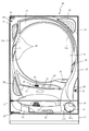
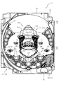
以下、本発明の実施形態について、添付図面を参照して説明する。まず、図1から図90を参照し、第1実施形態として、本発明をパチンコ遊技機(以下、単に「パチンコ機」という)10に適用した場合の一実施形態について説明する。図1は、第1実施形態におけるパチンコ機10の正面図であり、図2はパチンコ機10の遊技盤13の正面図であり、図3はパチンコ機10の背面図である。   Embodiments of the present invention will be described below with reference to the accompanying drawings. First, with reference to FIG. 1 to FIG. 90, an embodiment in which the present invention is applied to a pachinko gaming machine (hereinafter simply referred to as “pachinko machine”) 10 will be described as a first embodiment. 1 is a front view of a pachinko machine 10 according to the first embodiment, FIG. 2 is a front view of a game board 13 of the pachinko machine 10, and FIG. 3 is a rear view of the pachinko machine 10.

図1に示すように、パチンコ機10は、略矩形状に組み合わせた木枠により外殻が形成される外枠11と、その外枠11と略同一の外形形状に形成され外枠11に対して開閉可能に支持された内枠12とを備えている。外枠11には、内枠12を支持するために正面視(図1参照)左側の上下2カ所に金属製のヒンジ18が取り付けられ、そのヒンジ18が設けられた側を開閉の軸として内枠12が正面手前側へ開閉可能に支持されている。   As shown in FIG. 1, the pachinko machine 10 includes an outer frame 11 in which an outer shell is formed by a wooden frame combined in a substantially rectangular shape, and an outer shape that is substantially the same as the outer frame 11. And an inner frame 12 supported to be openable and closable. In order to support the inner frame 12, metal hinges 18 are attached to the outer frame 11 at two upper and lower portions on the left side when viewed from the front (see FIG. 1), and the side on which the hinge 18 is provided is used as an opening / closing axis. The frame 12 is supported so as to be openable and closable to the front front side.

内枠12には、多数の釘や入賞口26,27,28,63等を有する遊技盤13(図2参照)が裏面側から着脱可能に装着される。この遊技盤13の正面を球(遊技球)が流下することにより弾球遊技が行われる。なお、内枠12には、球を遊技盤13の正面領域に発射する球発射ユニット112a(図4参照)やその球発射ユニット112aから発射された遊技球を遊技盤13の正面領域まで誘導する発射レール(図示せず)等が取り付けられている。   A game board 13 (see FIG. 2) having a large number of nails, winning holes 26, 27, 28, 63 and the like is detachably mounted on the inner frame 12 from the back side. A ball ball game is played when a ball (game ball) flows down the front of the game board 13. The inner frame 12 guides a ball launch unit 112a (see FIG. 4) that launches a ball to the front area of the game board 13 and a game ball launched from the ball launch unit 112a to the front area of the game board 13. A firing rail (not shown) or the like is attached.

内枠12の正面側には、その正面上側を覆う正面枠14と、その下側を覆う下皿ユニット15とが設けられている。正面枠14及び下皿ユニット15を支持するために正面視(図1参照)左側の上下2カ所に金属製のヒンジ19が取り付けられ、そのヒンジ19が設けられた側を開閉の軸として正面枠14及び下皿ユニット15が正面手前側へ開閉可能に支持されている。なお、内枠12の施錠と正面枠14の施錠とは、シリンダ錠20の鍵穴21に専用の鍵を差し込んで所定の操作を行うことでそれぞれ解除される。   On the front side of the inner frame 12, a front frame 14 that covers the front upper side and a lower dish unit 15 that covers the lower side are provided. In order to support the front frame 14 and the lower plate unit 15, metal hinges 19 are attached to two upper and lower portions on the left side when viewed from the front (see FIG. 1). 14 and the lower pan unit 15 are supported so as to be openable and closable toward the front front side. The locking of the inner frame 12 and the locking of the front frame 14 are respectively released by inserting a dedicated key into the key hole 21 of the cylinder lock 20 and performing a predetermined operation.

正面枠14は、装飾用の樹脂部品や電気部品等を組み付けたものであり、その略中央部には略楕円形状に開口形成された窓部14cが設けられている。正面枠14の裏面側には2枚の板ガラスを有するガラスユニット16が配設され、そのガラスユニット16を介して遊技盤13の正面がパチンコ機10の正面側に視認可能となっている。   The front frame 14 is an assembly of decorative resin parts, electrical parts, and the like, and a window part 14c that is formed in an approximately elliptical shape is provided at a substantially central part thereof. A glass unit 16 having two plate glasses is disposed on the back side of the front frame 14, and the front of the game board 13 can be visually recognized on the front side of the pachinko machine 10 through the glass unit 16.

正面枠14には、球を貯留する上皿17が正面側へ張り出して上面を開放した略箱状に形成されており、この上皿17に賞球や貸出球などが排出される。上皿17の底面は正面視(図1参照)右側に下降傾斜して形成され、その傾斜により上皿17に投入された遊技球が球発射ユニット112a(図4参照)へと案内される。また、上皿17の上面には、枠ボタン22が設けられている。この枠ボタン22は、例えば、第3図柄表示装置(図示せず)で表示される演出のステージを変更したり、スーパーリーチの演出内容を変更したりする場合などに、遊技者により操作される。   On the front frame 14, an upper plate 17 that stores balls is formed in a substantially box shape that protrudes to the front side and opens the upper surface, and prize balls, rental balls, and the like are discharged to the upper plate 17. The bottom surface of the upper plate 17 is formed to be inclined downward to the right when viewed from the front (see FIG. 1), and the game ball thrown into the upper plate 17 is guided to the ball launching unit 112a (see FIG. 4). A frame button 22 is provided on the upper surface of the upper plate 17. This frame button 22 is operated by the player, for example, when changing the stage of the effect displayed on the third symbol display device (not shown) or changing the content of the effect of super reach. .

正面枠14には、その周囲(例えばコーナー部分)に各種ランプ等の発光手段が設けられている。これら発光手段は、大当たり時や所定のリーチ時等における遊技状態の変化に応じて、点灯又は点滅することにより発光態様が変更制御され、遊技中の演出効果を高める役割を果たす。窓部14cの周縁には、LED等の発光手段を内蔵した電飾部29〜33が設けられている。パチンコ機10においては、これら電飾部29〜33が大当たりランプ等の演出ランプとして機能し、大当たり時やリーチ演出時等には内蔵するLEDの点灯や点滅によって各電飾部29〜33が点灯または点滅して、大当たり中である旨、或いは大当たり一歩手前のリーチ中である旨が報知される。また、正面枠14の正面視(図1参照)左上部には、LED等の発光手段が内蔵され賞球の払い出し中とエラー発生時とを表示可能な表示ランプ34が設けられている。   The front frame 14 is provided with light emitting means such as various lamps around the periphery (for example, a corner portion). These light emitting means play a role of enhancing the effect of the game during the game by changing or controlling the light emission mode by turning on or blinking according to the change of the gaming state at the time of big hit or predetermined reach. On the peripheral edge of the window portion 14c, there are provided electric decoration portions 29 to 33 incorporating light emitting means such as LEDs. In the pachinko machine 10, these lighting parts 29 to 33 function as effect lamps such as jackpot lamps, and the lighting parts 29 to 33 are turned on by lighting or blinking of the built-in LEDs at the time of jackpot or reach effects. Alternatively, it blinks to notify that the jackpot is being hit or that the reach is one step before the jackpot. Further, in the upper left part of the front frame 14 as viewed from the front (see FIG. 1), there is provided a display lamp 34 which has a built-in light emitting means such as an LED and can display when a prize ball is being paid out and when an error occurs.

また、右側の電飾部32下側には、正面枠14の裏面側を視認できるように裏面側より透明樹脂を取り付けて小窓35が形成され、遊技盤13正面の貼着スペースK1(図2参照)に貼付される証紙等がパチンコ機10の正面から視認可能とされている。また、パチンコ機10においては、より煌びやかさを醸し出すために、電飾部29〜33の周りの領域にクロムメッキを施したABS樹脂製のメッキ部材36が取り付けられている。   In addition, a small window 35 is formed by attaching a transparent resin from the back surface side so that the back surface side of the front frame 14 can be visually recognized, on the lower side of the right illumination part 32, and a sticking space K1 (see FIG. 2) is visible from the front of the pachinko machine 10. In addition, in the pachinko machine 10, a plated member 36 made of ABS resin that is chrome-plated is attached to an area around the electric decoration parts 29 to 33 in order to bring out more gorgeousness.

窓部14cの下方には、貸球操作部40が配設されている。貸球操作部40には、度数表示部41と、球貸しボタン42と、返却ボタン43とが設けられている。パチンコ機10の側方に配置されるカードユニット(球貸しユニット)(図示せず)に紙幣やカード等を投入した状態で貸球操作部40が操作されると、その操作に応じて遊技球の貸出が行われる。具体的には、度数表示部41はカード等の残額情報が表示される領域であり、内蔵されたLEDが点灯して残額情報として残額が数字で表示される。球貸しボタン42は、カード等(記録媒体)に記録された情報に基づいて貸出球を得るために操作されるものであり、カード等に残額が存在する限りにおいて貸出球が上皿17に供給される。返却ボタン43は、カードユニットに挿入されたカード等の返却を求める際に操作される。なお、カードユニットを介さずに球貸し装置等から上皿17に遊技球が直接貸し出されるパチンコ機、いわゆる現金機では貸球操作部40が不要となるが、この場合には、貸球操作部40の設置部分に飾りシール等を付加して部品構成は共通のものとしても良い。カードユニットを用いたパチンコ機と現金機との共通化を図ることができる。   A ball rental operation unit 40 is disposed below the window 14c. The ball lending operation unit 40 is provided with a frequency display unit 41, a ball lending button 42, and a return button 43. When the lending operation unit 40 is operated in a state where a bill or a card is inserted into a card unit (ball lending unit) (not shown) disposed on the side of the pachinko machine 10, a game ball is operated according to the operation. Is lent out. Specifically, the frequency display unit 41 is an area in which the remaining amount information such as a card is displayed, and the built-in LED is lit to display the remaining amount as the remaining amount information. The ball lending button 42 is operated to obtain a lending ball based on information recorded on a card or the like (recording medium), and the lending ball is supplied to the upper plate 17 as long as there is a remaining amount on the card or the like. Is done. The return button 43 is operated when requesting the return of a card or the like inserted into the card unit. In addition, in a pachinko machine in which game balls are lent directly to the upper plate 17 from a ball lending device or the like without using a card unit, a so-called cash machine does not require the ball lending operation unit 40. In this case, the ball lending operation unit A decorative seal or the like may be added to the 40 installed portions so that the component configuration is common. A pachinko machine using a card unit and a cash machine can be shared.

上皿17の下側に位置する下皿ユニット15には、その中央部に上皿17に貯留しきれなかった遊技球を貯留するための下皿50が上面を開放した略箱状に形成されている。下皿50の右側には、球を遊技盤13の正面へ打ち込むために遊技者によって操作される操作ハンドル51が配設される。   In the lower tray unit 15 located on the lower side of the upper tray 17, a lower tray 50 for storing game balls that could not be stored in the upper tray 17 is formed in a substantially box shape having an open upper surface. ing. On the right side of the lower plate 50, an operation handle 51 that is operated by a player to drive a ball into the front of the game board 13 is disposed.

操作ハンドル51の内部には、球発射ユニット112aの駆動を許可するためのタッチセンサ51aと、押下操作している期間中には遊技球の発射を停止する発射停止スイッチ51bと、操作ハンドル51の回動操作量(回動位置)を電気抵抗の変化により検出する可変抵抗器(図示せず)などが内蔵されている。操作ハンドル51が遊技者によって右回りに回動操作されると、タッチセンサ51aがオンされると共に可変抵抗器の抵抗値が回動操作量に対応して変化し、その可変抵抗器の抵抗値に対応した強さ(発射強度)で遊技球が発射され、これにより遊技者の操作に対応した飛び量で遊技盤13の正面へ遊技球が打ち込まれる。また、操作ハンドル51が遊技者により操作されていない状態においては、タッチセンサ51aおよび発射停止スイッチ51bがオフとなっている。   Inside the operation handle 51, there are a touch sensor 51a for permitting the driving of the ball launch unit 112a, a launch stop switch 51b for stopping the launch of the game ball during the pressing operation, and the operation handle 51. A variable resistor (not shown) that detects the amount of rotation operation (rotation position) based on a change in electrical resistance is incorporated. When the operation handle 51 is rotated clockwise by the player, the touch sensor 51a is turned on and the resistance value of the variable resistor changes in accordance with the amount of rotation operation. The resistance value of the variable resistor The game ball is fired at a strength (launch strength) corresponding to the game ball, and the game ball is driven in front of the game board 13 with a jump amount corresponding to the player's operation. Further, when the operation handle 51 is not operated by the player, the touch sensor 51a and the firing stop switch 51b are turned off.

下皿50の正面下方部には、下皿50に貯留された遊技球を下方へ排出する際に操作するための球抜きレバー52が設けられている。この球抜きレバー52は、常時、右方向に付勢されており、その付勢に抗して左方向へスライドさせることにより、下皿50の底面に形成された底面口が開口して、その底面口から遊技球が自然落下して排出される。この球抜きレバー52の操作は、通常、下皿50の下方に下皿50から排出された遊技球を受け取る箱(一般に「千両箱」と称される)を置いた状態で行われる。下皿50の右方には、上述したように操作ハンドル51が配設され、下皿50の左方には灰皿53が取り付けられている。   In the lower part of the front of the lower plate 50, a ball removal lever 52 is provided for operation when the game balls stored in the lower plate 50 are discharged downward. The ball removal lever 52 is always urged to the right, and by sliding to the left against the urging, the bottom opening formed on the bottom surface of the lower plate 50 opens, A game ball naturally falls from the bottom opening and is discharged. The operation of the ball pulling lever 52 is normally performed in a state where a box (generally referred to as “a thousand box”) for receiving the game balls discharged from the lower plate 50 is placed below the lower plate 50. As described above, the operation handle 51 is disposed on the right side of the lower plate 50, and the ashtray 53 is attached on the left side of the lower plate 50.

図2に示すように、遊技盤13は、正面視略正方形状に切削加工したベース板60に、球案内用の多数の釘(図示せず)や風車の他、レール61,62、2つの一般入賞口63、比較的大型の可動入球役物装置300、その可動入球役物装置300の左下方位置に配設される左始動入賞口26、中央位置に配設される中始動入賞口28、右下方位置に配設される右始動入賞口27を備え、その周縁部が内枠12(図1参照)の裏面側に取り付けられる。   As shown in FIG. 2, the game board 13 includes a base plate 60 cut into a substantially square shape when viewed from the front, a plurality of nails (not shown) for ball guidance, a windmill, rails 61, 62, A general winning opening 63, a relatively large movable winning combination device 300, a left starting winning opening 26 provided at a lower left position of the movable incoming combination device 300, and a middle starting winning arrangement provided at a central position. The opening 28 is provided with a right start winning opening 27 disposed at a lower right position, and the peripheral edge thereof is attached to the back side of the inner frame 12 (see FIG. 1).

ベース板60は光透過性の樹脂材料からなり、その正面側からベース板60の後面側に配設された各種構造体を遊技者に視認させることが可能に形成される。   The base plate 60 is made of a light-transmitting resin material, and is formed so that the player can visually recognize various structures disposed on the rear surface side of the base plate 60 from the front side.

一般入賞口63、左始動入賞口26、右始動入賞口27、中始動入賞口28、可動入球役物装置300は、ルータ加工によってベース板60に形成された貫通穴に配設され、遊技盤13の正面側からタッピングネジ等により固定されている。   The general winning port 63, the left starting winning port 26, the right starting winning port 27, the middle starting winning port 28, and the movable winning ball accessory device 300 are arranged in a through hole formed in the base plate 60 by router processing. It is fixed from the front side of the panel 13 with a tapping screw or the like.

遊技領域内に放り込まれた遊技球は、その流下の過程で無作為に普通入賞口63に入球したり、左始動入賞口26、中始動入賞口28又は右始動入賞口27に入球したり、あるいは作動時(開放時)の可動入球役物装置300に入球したりする。   The game balls thrown into the game area randomly enter the normal winning opening 63, or enter the left starting winning opening 26, the middle starting winning opening 28 or the right starting winning opening 27 in the process of flowing down. Or enter the movable ball accessory device 300 during operation (when opened).

各入賞口に入球した遊技球は遊技盤13に形成された貫通穴を通じて遊技盤13の裏側へ回収される。   The game balls that have entered the winning holes are collected to the back side of the game board 13 through through holes formed in the game board 13.

一方、可動入球役物装置300内に流入した遊技球は、さらにその内部で流下や転動、上昇等の過程を経て振り分け動作が行われた後に排出され、遊技盤13の裏側へ回収される。なお、可動入球役物装置300内での振り分け動作については、別の図面を参照しながら後述する。   On the other hand, the game balls that have flowed into the movable entrance ball apparatus 300 are further discharged through a process of flow, rolling, and rising, and then collected and collected to the back of the game board 13. The In addition, the sorting operation in the movable ball accessory device 300 will be described later with reference to another drawing.

可動入球役物装置300は、特定の条件が満たされた場合(例えば、左始動入賞口26、中始動入賞口28又は右始動入賞口27に遊技球が入球した場合であって、所定の特別図柄が小当たりの態様で停止表示された場合)に作動し、遊技球の流入を可能にする。すなわち可動入球役物装置300は、遊技領域の上部位置に設けられた羽部312(いわゆる羽根部材)を有しており、この羽部312は、例えばソレノイド317(図14参照)を用いたリンク機構の働きにより、盤面に沿って所定角度だけ往復回転する。   The movable ball accessory device 300 is a case where a specific condition is satisfied (for example, when a game ball enters the left start winning port 26, the middle start winning port 28, or the right start winning port 27, The special symbol is stopped and displayed in the form of a small hit) and allows the inflow of game balls. That is, the movable ball accessory device 300 has a wing 312 (so-called wing member) provided at an upper position of the game area, and the wing 312 uses, for example, a solenoid 317 (see FIG. 14). By the function of the link mechanism, it reciprocates by a predetermined angle along the board surface.

羽部312は、略直立した状態にあり、可動入球役物装置300への遊技球の流入は常に不能となっている。可動入球役物装置300が作動すると、羽部312がその基端部を中心として遊技領域内の左右方向へ倒れるようにして変位することで可動入球役物装置300への遊技球の流入を可能にする。羽部312は遊技領域内の上部位置、特に遊技球が最初に打ち込まれる位置の近くにあることから、可動入球役物装置300の作動時に遊技領域内に打ち込まれた遊技球は、上部位置の釘に誘導されて容易に羽部312に到達し、そのまま羽部312に案内されて可動入球役物装置300に流入する。   The wing 312 is in a substantially upright state, and the inflow of the game ball into the movable incoming ball accessory device 300 is always impossible. When the movable ball accessory device 300 is actuated, the wing portion 312 is displaced so as to fall in the left-right direction within the game area around the base end portion thereof, so that the game ball flows into the movable ball accessory device 300. Enable. Since the wing 312 is near the upper position in the game area, in particular, near the position where the game ball is first driven, the game ball that is driven into the game area when the movable ball accessory device 300 is operated is The wings 312 are easily guided by the nails and are guided to the wings 312 and flow into the movable ball accessory device 300 as they are.

可動入球役物装置300は、規定の条件が満たされた場合(可動入球役物装置300の内部に設けられたいずれかの特定領域を遊技球が通過した場合)にも作動し、可動入球役物装置300への入球を可能にする。なお、可動入球役物装置300内の特定領域についてはさらに後述する。   The movable incoming ball accessory device 300 operates even when a prescribed condition is satisfied (when a game ball passes through any specific area provided in the movable incoming ball accessory device 300). It is possible to enter the entrance game apparatus 300. In addition, the specific area | region in the movable entrance ball accessory apparatus 300 is further mentioned later.

また、可動入球役物装置300内には、後述する可変板352(図12参照)が配置されている。可変板352は、遊技球をノーマルルートに誘導するかスペシャルルートに誘導するかの振り分け動作を行う。遊技球がノーマルルートに誘導されれば、その後に大当りとなる確率は低いが、遊技球がスペシャルルートに誘導されれば、遊技球がノーマルルートに誘導された場合と比較してその後に大当りとなる確率が高くなる。   Further, a variable plate 352 (see FIG. 12), which will be described later, is disposed in the movable incoming ball accessory device 300. The variable plate 352 performs a sorting operation for guiding the game ball to the normal route or the special route. If the game ball is guided to the normal route, the probability of a big hit after that is low, but if the game ball is guided to the special route, it will be a big hit after that compared to the case where the game ball is guided to the normal route. The probability of becoming higher.

遊技盤13の正面中央部分は、正面枠14の窓部14c(図1参照)を通じて内枠12の正面側から視認することができる。以下に、主に図2を参照して、遊技盤13の構成について説明する。   The front center portion of the game board 13 can be viewed from the front side of the inner frame 12 through the window portion 14c of the front frame 14 (see FIG. 1). The configuration of the game board 13 will be described below mainly with reference to FIG.

遊技盤13の正面には、帯状の金属板を略円弧状に屈曲加工して形成した外レール62が植立され、その外レール62の内側位置には外レール62と同様に帯状の金属板で形成した円弧状の内レール61が植立される。この内レール61と外レール62とにより遊技盤13の正面外周が囲まれ、遊技盤13とガラスユニット16(図1参照)とにより前後が囲まれることにより、遊技盤13の正面には、球の挙動により遊技が行われる遊技領域が形成される。遊技領域は、遊技盤13の正面であって2本のレール61,62とレール間を繋ぐ樹脂製の外縁部材73とにより区画して形成される領域(入賞口等が配設され、発射された遊技球が流下する領域)である。   An outer rail 62 formed by bending a band-shaped metal plate into a substantially arc shape is planted on the front surface of the game board 13, and the band-shaped metal plate is located on the inner side of the outer rail 62 in the same manner as the outer rail 62. The arc-shaped inner rail 61 formed by the above is planted. The inner periphery of the game board 13 is surrounded by the inner rail 61 and the outer rail 62, and the front and rear are surrounded by the game board 13 and the glass unit 16 (see FIG. 1). A game area in which a game is played is formed by the behavior of. The game area is an area formed in front of the game board 13 and defined by the two rails 61 and 62 and a resin outer edge member 73 connecting the rails (a winning opening is provided and fired). Area where game balls flow down).

2本のレール61,62は、球発射ユニット112a(図4参照)から発射された遊技球を遊技盤13上部へ案内するために設けられたものである。内レール61の先端部分(図2の左上部)には戻り球防止部材68が取り付けられ、一旦、遊技盤13の上部へ案内された遊技球が再度球案内通路内に戻ってしまうといった事態が防止される。外レール62の先端部(図2の右上部)には、球の最大飛翔部分に対応する位置に返しゴム69が取り付けられ、所定以上の勢いで発射された遊技球は、返しゴム69に当たって、勢いが減衰されつつ中央部側へ跳ね返される。   The two rails 61 and 62 are provided to guide the game balls launched from the ball launch unit 112a (see FIG. 4) to the upper part of the game board 13. A return ball prevention member 68 is attached to the front end portion of the inner rail 61 (upper left portion in FIG. 2), and the game ball once guided to the upper portion of the game board 13 returns to the ball guide passage again. Is prevented. A return rubber 69 is attached to the tip of the outer rail 62 (upper right part in FIG. 2) at a position corresponding to the maximum flying portion of the ball, and the game ball launched at a predetermined momentum or more hits the return rubber 69, It is bounced back to the center while the momentum is attenuated.

遊技領域の正面視左側下部(図2の左側下部)には、発光手段である複数のLED及び7セグメント表示器を備える第1図柄表示装置37A,37Bが配設されている。第1図柄表示装置37A,37Bは、主制御装置110(図4参照)で行われる各制御に応じた表示がなされるものであり、主にパチンコ機10の遊技状態の表示が行われる。本実施形態では、第1図柄表示装置37A,37Bは、球が、左右始動入賞口26,27へ入賞したか、中始動入賞口28へ入賞したかに応じて使い分けられるように構成されている。具体的には、球が、左右始動入賞口26,27へ入賞した場合には、第1図柄表示装置37Aが作動し、一方で、球が、中始動入賞口28へ入賞した場合には、第1図柄表示装置37Bが作動するように構成されている。   First symbol display devices 37A and 37B each having a plurality of LEDs and a 7-segment display as light emitting means are disposed in the lower left portion of the game area when viewed from the front (lower left portion in FIG. 2). The first symbol display devices 37A and 37B display according to each control performed by the main control device 110 (see FIG. 4), and mainly display the gaming state of the pachinko machine 10. In the present embodiment, the first symbol display devices 37A and 37B are configured to be selectively used depending on whether the ball has won the left and right start winning ports 26 and 27 or the middle start winning port 28. . Specifically, when the ball has won the left and right start winning ports 26 and 27, the first symbol display device 37A is operated, while when the ball has won the middle start winning port 28, The first symbol display device 37B is configured to operate.

また、第1図柄表示装置37A,37Bは、LEDにより、パチンコ機10が時短中か通常中であるかを点灯状態により示したり、変動中であるか否かを点灯状態により示したり、停止図柄が小当たりに対応した図柄かを点灯状態により示したり、保留球数を点灯状態により示すと共に、7セグメント表示装置により、大当たり中のラウンド数やエラー表示を行う。なお、複数のLEDは、それぞれのLEDの発光色(例えば、赤、緑、青)が異なるよう構成され、その発光色の組み合わせにより、少ないLEDでパチンコ機10の各種遊技状態を示唆することができる。   In addition, the first symbol display devices 37A and 37B indicate by LED whether the pachinko machine 10 is short-running or normal, by a lighting state, whether it is changing, by a lighting state, Whether the symbol corresponds to a small hit is indicated by a lighting state, the number of held balls is indicated by a lighting state, and the number of rounds or a big hit is displayed by a 7-segment display device. The plurality of LEDs are configured to have different emission colors (for example, red, green, and blue) of each LED, and the combination of the emission colors may suggest various gaming states of the pachinko machine 10 with a small number of LEDs. it can.

尚、本パチンコ機10では、第1センサ311bへ入賞があったことを契機として抽選(可動入球役物装置300を流下する遊技球が特定領域を通るか否かの抽選)が行われる。パチンコ機10は、その抽選において、大当たりか否かの当否判定(大当たり抽選)を行うと共に、大当たりと判定した場合はその大当たり種別の判定も行う。ここで判定される大当たり種別としては、16R大当たり、7R大当たり、3R大当たり、が用意されている。第1図柄表示装置37A,37Bには、大当たりである場合はその大当たり種別に応じた図柄が示される。   In the present pachinko machine 10, a lottery (lottery of whether or not a game ball flowing down the movable pitching accessory device 300 passes through a specific area) is performed in response to the winning of the first sensor 311b. In the lottery, the pachinko machine 10 determines whether or not it is a big hit (big hit lottery), and also determines the type of the big hit if it is determined to be a big hit. The jackpot types determined here are 16R jackpot, 7R jackpot, and 3R jackpot. In the first symbol display devices 37A and 37B, in the case of a jackpot, a symbol corresponding to the jackpot type is displayed.

ここで、「16R大当たり」とは、最大ラウンド数が16ラウンドの大当たりのことであり、「7R大当たり」とは、最大ラウンド数が7ラウンドの大当たりのことであり、「3R大当たり」とは、最大ラウンド数が3ラウンドの大当たりのことである。   Here, “16R jackpot” means a jackpot of 16 rounds, “7R jackpot” means a jackpot of seven rounds, and “3R jackpot” The maximum number of rounds is a big hit of 3 rounds.

1ラウンドとは、大当たりの賞球個数を区切る単位のことである。本実施形態では、1ラウンドの間は、羽部312が傾倒し、第1センサ311b(図14参照)が開放され、30秒間経過するか、遊技球が10個第1センサ311bを通過すると終了となる。第1センサ311bを遊技球が1個通過することにより10個の賞球があるので、1ラウンドごとに、約100個の賞球を得ることができる。   One round is a unit for dividing the number of winning balls. In the present embodiment, during one round, the wing part 312 tilts and the first sensor 311b (see FIG. 14) is released, and when 30 seconds have passed or 10 game balls have passed the first sensor 311b, the process ends. It becomes. Since there are ten prize balls by passing one game ball through the first sensor 311b, about 100 prize balls can be obtained for each round.

なお、本実施形態では、1ラウンド目は、遊技球がV入賞部材382(図10参照)を通過することで終了となるので、1ラウンド目は賞球が無い。即ち、3R大当たりでは、最大で約200個の賞球が、7R大当たりでは、最大で約600個の賞球が、16R大当たりでは、最大で約1500個の賞球が得られる。   In the present embodiment, the first round ends when the game ball passes the V winning member 382 (see FIG. 10), and therefore the first round has no prize ball. In other words, a maximum of about 200 prize balls can be obtained for 3R jackpots, a maximum of about 600 prize balls for 7R jackpots, and a maximum of about 1500 prize balls for 16R jackpots.

時短状態(時短中)とは、大当たり確率がそのままで第2図柄の当たり確率のみがアップして中始動入賞口28へ遊技球が入賞し易い遊技の状態のことをいう。一方、パチンコ機10が通常中とは、時短中でない遊技の状態(第2図柄の当たり確率がアップしていない状態)である。   The short time state (short time) means a game state in which it is easy to win a game ball to the middle start winning opening 28 with the jackpot probability as it is and only the second pattern hit probability is increased. On the other hand, when the pachinko machine 10 is in a normal state, the game is not in a short time (a state in which the probability of winning the second symbol is not increased).

時短中は、第2図柄の当たり確率がアップするだけではなく、中始動入賞口28に付随する可変入賞装置650の可変板652が開放される時間も変更され、通常中と比して長い時間が設定される。可変入賞装置650の可変板652が開放された状態(開放状態)にある場合は、その可変入賞装置650の可変板652が閉鎖された状態(閉鎖状態)にある場合と比して、中始動入賞口28へ遊技球が入賞しやすい状態となる。よって、時短中は、中始動入賞口28へ遊技球が入賞し易い状態となり、羽部312を開放状態にし易くすることができる。   During the time reduction, not only does the probability of winning the second symbol increase, but also the time for opening the variable plate 652 of the variable winning device 650 associated with the middle start winning opening 28 is changed, which is longer than normal. Is set. When the variable plate 652 of the variable prize winning device 650 is in the opened state (open state), compared to the case where the variable plate 652 of the variable prize winning device 650 is in the closed state (closed state), the middle start It becomes easy for the game ball to enter the winning opening 28. Therefore, during the short time, it becomes easy for the game ball to win the middle start winning opening 28, and the wings 312 can be easily opened.

なお、時短中において、中始動入賞口28に付随する可変入賞装置650の可変板652の開放時間を変更するのではなく、または、その開放時間を変更することに加えて、1回の当たりで可変入賞装置650の可変板652が開放する回数を通常中よりも増やす変更を行うものとしてもよい。また、時短中において、第2図柄の当たり確率は変更せず、中始動入賞口28に付随する可変入賞装置650の可変板652が開放される時間および1回の当たりで可変入賞装置650の可変板652が開放する回数の少なくとも一方を変更するものとしてもよい。また、時短中において、中始動入賞口28に付随する可変入賞装置650の可変板652が開放される時間や、1回の当たりで可変入賞装置650の可変板652を開放する回数は変更せず、第2図柄の当たり確率だけを、通常中と比してアップするよう変更するものであってもよい。   It should be noted that, in the short time, instead of changing the opening time of the variable plate 652 of the variable winning device 650 associated with the middle start winning opening 28, or in addition to changing the opening time, per hit It is also possible to change the number of times that the variable plate 652 of the variable winning device 650 is opened more than usual. In addition, during the time saving, the winning probability of the second symbol is not changed, and the variable winning device 650 is variable at the time when the variable plate 652 of the variable winning device 650 associated with the middle start winning port 28 is opened and once. At least one of the number of times the plate 652 is opened may be changed. In addition, the time during which the variable plate 652 of the variable winning device 650 associated with the middle start winning port 28 is opened and the number of times the variable plate 652 of the variable winning device 650 is opened per time are not changed during the short time. , Only the probability of hitting the second symbol may be changed so as to increase compared to the normal probability.

遊技領域には、球が入賞することにより5個から15個の遊技球が賞球として払い出される複数の一般入賞口63が配設されている。また、遊技領域の中央部分には、可動入球役物装置300が配設されている。可動入球役物装置300には、左右始動入賞口26,27及び中始動入賞口28への入賞(始動入賞)をトリガとして、第1図柄表示装置37A,37Bにおける変動表示と同期させながら、開閉動作する羽部312と、スルーゲート67の遊技球の通過をトリガとして第2図柄を変動表示するLEDで構成される第2図柄表示装置(図示せず)とが設けられている。また、可動入球役物装置300には、外周を囲むようにして、センターフレーム86が配設されている。   The game area is provided with a plurality of general winning holes 63 through which 5 to 15 game balls are paid out as winning balls when the balls win. In addition, a movable ball accessory device 300 is disposed at the center of the game area. In the movable ball accessory device 300, the winnings (starting winnings) at the left and right starting winning ports 26 and 27 and the middle starting winning port 28 are used as a trigger while synchronizing with the variation display on the first symbol display devices 37A and 37B. A wing portion 312 that opens and closes and a second symbol display device (not shown) configured by LEDs that variably display the second symbol triggered by the passage of a game ball through the through gate 67 are provided. Moreover, the center frame 86 is arrange | positioned so that the outer periphery of movable movable accessory device 300 may be enclosed.

第2図柄表示装置は、球がスルーゲート67を通過する毎に表示図柄(第2図柄(図示せず))としての「○」の図柄と「×」の図柄とを所定時間交互に点灯させる変動表示を行うものである。パチンコ機10では、球がスルーゲート67を通過したことが検出されると、当たり抽選が行われる。その当たり抽選の結果、当たりであれば、第2図柄表示装置において、第2図柄の変動表示後に「○」の図柄が停止表示される。また、当たり抽選の結果、外れであれば、第2図柄表示装置において、第2図柄の変動表示後に「×」の図柄が停止表示される。   Each time the sphere passes through the through gate 67, the second symbol display device alternately turns on the symbol “◯” and the symbol “X” as a display symbol (second symbol (not shown)) for a predetermined time. A variable display is performed. In the pachinko machine 10, when it is detected that the ball has passed through the through gate 67, a winning lottery is performed. As a result of the winning lottery, if the winning symbol is a winning symbol, the symbol “◯” is stopped and displayed on the second symbol display device after the variation of the second symbol is displayed. Further, if the winning lottery results, the symbol of “x” is stopped and displayed on the second symbol display device after the variation of the second symbol is displayed.

パチンコ機10は、第2図柄表示装置における変動表示が所定図柄(本実施形態においては「○」の図柄)で停止した場合に、中始動入賞口28に付随された可変入賞装置650の可変板652が所定時間だけ作動状態となる(開放される)よう構成されている。   When the variable display on the second symbol display device stops at a predetermined symbol (in the present embodiment, the symbol “◯”), the pachinko machine 10 has a variable plate of the variable winning device 650 attached to the middle start winning port 28. 652 is configured to be activated (opened) for a predetermined time.

第2図柄の変動表示にかかる時間は、遊技状態が通常中の場合よりも、時短中の方が短くなるように設定される。これにより、時短中は、第2図柄の変動表示が短い時間で行われるので、当たり抽選を通常中よりも多く行うことができる。よって、当たり抽選において当たりとなる機会が増えるので、中始動入賞口28の可変入賞装置650の可変板652が開放状態となる機会を遊技者に多く与えることができる。よって、時短中は、中始動入賞口28へ遊技球が入賞しやすい状態とすることができる。   The time required for the variable display of the second symbol is set to be shorter in the shorter time than in the normal gaming state. As a result, during the time reduction, since the variation display of the second symbol is performed in a short time, the winning lottery can be performed more than during normal time. Therefore, since the chances for winning in the winning lottery increase, the player can be given many opportunities to open the variable plate 652 of the variable winning device 650 of the middle start winning opening 28. Therefore, it is possible to make it easier for the game ball to win the middle start winning opening 28 during the short time.

なお、時短中において、当たり確率を高める、1回に当たりに対する可変入賞装置650の可変板652の開放時間や開放回数を増やすなど、その他の方法によっても、時短中に中始動入賞口28へ遊技球が入賞しやすい状態としている場合は、第2図柄の変動表示にかかる時間を遊技状態にかかわらず一定としてもよい。一方、第2図柄の変動表示にかかる時間を、時短中において通常中よりも短く設定する場合は、当たり確率を遊技状態にかかわらず一定にしてもよいし、また、1回の当たりに対する可変入賞装置650の可変板652の開放時間や開放回数を遊技状態にかかわらず一定にしてもよい。   It should be noted that the game ball can be moved to the middle start winning opening 28 during the time reduction by increasing the probability of winning during the time reduction or increasing the opening time or the number of times of opening of the variable plate 652 of the variable winning device 650 per time. When it is in a state where it is easy to win a prize, the time required for the variable display of the second symbol may be constant regardless of the gaming state. On the other hand, when the time required to display the variation of the second symbol is set to be shorter than normal during the time reduction, the winning probability may be constant regardless of the gaming state, and the variable winning for one hit The opening time and the number of opening times of the variable plate 652 of the device 650 may be constant regardless of the gaming state.

スルーゲート67は、可動入球役物装置300の左右において遊技盤に組み付けられ、遊技盤に発射された遊技球の一部が通過可能に構成されている。スルーゲート67を遊技球が通過すると、第2図柄の当たり抽選が行われる。当たり抽選の後、第2図柄表示装置にて変動表示を行い、当たり抽選の結果が当たりであれば、変動表示の停止図柄として「○」の図柄を表示し、当たり抽選の結果が外れであれば、変動表示の停止図柄として「×」の図柄を表示する。   The through gate 67 is assembled to the game board on the left and right sides of the movable ball accessory device 300 so that a part of the game ball launched on the game board can pass therethrough. When the game ball passes through the through gate 67, a lottery for the second symbol is performed. After winning the lottery, the 2nd symbol display device displays a variation, and if the winning lottery results, the symbol “○” is displayed as the variable display stop symbol, and the winning lottery result may be off For example, the symbol “x” is displayed as the stop symbol of the variable display.

球のスルーゲート67の通過回数は、合計で最大4回まで保留され、その保留球数が上述した第1図柄表示装置37A,37Bにより表示されると共に第2図柄保留ランプ(図示せず)においても点灯表示される。第2図柄保留ランプは、最大保留数分の4つ設けられ、可動入球役物装置300の下方に左右対称に配設されている。   The total number of passes through the through-gate 67 of the sphere is held up to a maximum of 4 times, and the number of held balls is displayed by the above-described first symbol display devices 37A and 37B and at the second symbol hold lamp (not shown). Is also displayed. Four second pattern reservation lamps are provided corresponding to the maximum number of reservations, and are arranged symmetrically below the movable incoming ball accessory device 300.

なお、第2図柄の変動表示は、本実施形態のように、第2図柄表示装置において複数のランプの点灯と非点灯を切り換えることにより行うものの他、第1図柄表示装置37A,37B及び可動入球役物装置300の一部を使用して行うようにしても良い。同様に、第2図柄保留ランプの点灯を可動入球役物装置300の一部で行うようにしても良い。また、スルーゲート67の遊技球の通過に対する最大保留球数は4回に限定されるものでなく、3回以下、又は、5回以上の回数(例えば、8回)に設定しても良い。また、スルーゲート67の組み付け数は1つに限定されるものではなく、複数(例えば、2つ)であっても良い。また、スルーゲート67の組み付け位置は可動入球役物装置300の左右に限定されるものではなく、例えば、可動入球役物装置300の上方でも良い。また、第1図柄表示装置37A,37Bにより保留球数が示されるので、第2図柄保留ランプにより点灯表示を行わないものとしてもよい。   In addition, the variation display of the second symbol is performed by switching on and off of a plurality of lamps in the second symbol display device as in the present embodiment, as well as the first symbol display devices 37A and 37B and the movable input. A part of the ball accessory device 300 may be used. Similarly, the second symbol holding lamp may be turned on by a part of the movable ball accessory device 300. Further, the maximum number of reserved balls with respect to the passage of the game ball of the through gate 67 is not limited to four times, and may be set to three times or less, or five times or more (for example, eight times). Further, the number of through gates 67 to be assembled is not limited to one, and may be plural (for example, two). Moreover, the assembly position of the through gate 67 is not limited to the left and right sides of the movable incoming ball accessory device 300, and may be, for example, above the movable incoming ball accessory device 300. In addition, since the number of reserved balls is indicated by the first symbol display devices 37A and 37B, the second symbol hold lamp may not perform lighting display.

可動入球役物装置300の左右下方には、球が入賞し得る左右始動入賞口26,27が配設されている。この左右始動入賞口26,27へ遊技球が入賞すると遊技盤13の裏面側に設けられる左始動入賞口スイッチ210a、右始動入賞口スイッチ210bがオンとなり、その左始動入賞口スイッチ210a、右始動入賞口スイッチ210bのオンに起因して主制御装置110(図4参照)で抽選がなされ、その抽選結果に応じた表示が第1図柄表示装置37Aで示されると共に、羽部312が所定回数(本実施形態では1回)開放し、所定期間後(本実施形態では0.5秒後)閉鎖される。   Left and right starting winning holes 26 and 27 through which a ball can win are arranged at the lower left and right of the movable ball accessory device 300. When a game ball wins the left and right start winning ports 26 and 27, the left start winning port switch 210a and the right start winning port switch 210b provided on the back side of the game board 13 are turned on, and the left start winning port switch 210a and right start are turned on. A lottery is made in the main controller 110 (see FIG. 4) due to the turn-on of the prize opening switch 210b, and a display corresponding to the lottery result is shown in the first symbol display device 37A, and the wing part 312 is displayed a predetermined number of times ( It is opened once in this embodiment, and is closed after a predetermined period (0.5 seconds in this embodiment).

一方、左右始動入賞口26,27の正面視中央側には、球が入賞し得る中始動入賞口28が配設されている。この中始動入賞口28へ遊技球が入賞すると遊技盤13の裏面側に設けられる中始動入賞口スイッチ(図示せず)がオンとなり、その中始動入賞口スイッチ)のオンに起因して主制御装置110(図4参照)で抽選がなされ、その抽選結果に応じた表示が第1図柄表示装置37Bで示されると共に、羽部312が所定回数(本実施形態では2回)開放と閉鎖とを繰り返す(開放する期間は0.5秒で、1回目と2回目との間隔は2秒間)。   On the other hand, a middle start winning opening 28 through which a ball can win is disposed on the center side of the left and right starting winning openings 26 and 27 as viewed from the front. When a game ball wins the middle start winning opening 28, a middle start winning opening switch (not shown) provided on the back side of the game board 13 is turned on, and the main control is caused by the turning on of the start winning opening switch. A lottery is made by the device 110 (see FIG. 4), and a display corresponding to the lottery result is shown by the first symbol display device 37B, and the wing 312 is opened and closed a predetermined number of times (in this embodiment, twice). Repeat (open period is 0.5 seconds, interval between first and second is 2 seconds).

各始動入賞口26,27,28は、1/1で小当たりとなるように抽選を行っている。そのため、本実施形態において、各始動入賞口26,27,28を遊技球が通過することによる大当たりの抽選は無い。その抽選後、ランダムに選択されたオープニング期間(1〜5秒間)後に、羽部312が所定回数の開放と閉鎖とを繰り替えす。   Each start winning opening 26, 27, 28 is drawn in a lottery so that the winning prize is 1/1. Therefore, in this embodiment, there is no jackpot lottery due to the game balls passing through the start winning holes 26, 27, 28. After the lottery, the wing 312 repeats opening and closing a predetermined number of times after a randomly selected opening period (1 to 5 seconds).

また、左右始動入賞口26,27および中始動入賞口28は、それぞれ、球が入賞すると5個の遊技球が賞球として払い出される入賞口の1つにもなっている。なお、本実施形態においては、左右始動入賞口26,27へ遊技球が入賞した場合に払い出される賞球数と中始動入賞口28へ遊技球が入賞した場合に払い出される賞球数とを同じに構成したが、左右始動入賞口26,27へ遊技球が入賞した場合に払い出される賞球数と中始動入賞口28へ遊技球が入賞した場合に払い出される賞球数とを異なる数、例えば、左右始動入賞口26,27へ遊技球が入賞した場合に払い出される賞球数を3個とし、中始動入賞口28へ遊技球が入賞した場合に払い出される賞球数を5個として構成してもよい。   Each of the left and right start winning ports 26 and 27 and the middle start winning port 28 is also one of the winning ports from which five game balls are paid out as winning balls when a ball is won. In this embodiment, the number of prize balls to be paid out when a game ball wins the left and right start winning holes 26 and 27 is the same as the number of prize balls to be paid out when a game ball wins the middle start prize opening 28. However, the number of prize balls to be paid out when a game ball is won at the left and right start winning openings 26 and 27 is different from the number of prize balls to be paid out when a game ball is won at the middle start prize opening 28, for example, The number of prize balls to be paid out when a game ball is won at the left and right start winning openings 26 and 27 is three, and the number of prize balls to be paid out when a game ball is won at the middle start prize opening 28 is five. May be.

中始動入賞口28には可変入賞装置650が付随されている。この可変入賞装置650の可変板652は開閉可能に構成されており、通常は可変入賞装置650の可変板652が閉鎖状態(縮小状態)となって、球が中始動入賞口28へ入賞しにくい状態となっている。一方、スルーゲート67への遊技球の通過を契機として行われる第2図柄の変動表示の結果、「○」の図柄が第2図柄表示装置に表示された場合、可変入賞装置650の可変板652が開放状態(拡大状態)となり、球が中始動入賞口28へ入賞しやすい状態となる。   A variable winning device 650 is attached to the middle start winning opening 28. The variable plate 652 of the variable winning device 650 is configured to be openable and closable. Normally, the variable plate 652 of the variable winning device 650 is in a closed state (reduced state), and it is difficult for the ball to win the middle start winning port 28. It is in a state. On the other hand, when the symbol “◯” is displayed on the second symbol display device as a result of the variation display of the second symbol that is triggered by the passing of the game ball to the through gate 67, the variable plate 652 of the variable winning device 650 is displayed. Is in an open state (enlarged state), and the ball is in a state where it is easy to win the middle start winning opening 28.

上述した通り、時短中は、通常中と比して第2図柄の当たり確率が高く、また、第2図柄の変動表示にかかる時間も短いので、第2図柄の変動表示において「○」の図柄が表示され易くなって、可変入賞装置650の可変板652が開放状態(拡大状態)となる回数が増える。更に、時短中は、可変入賞装置650の可変板652が開放される時間も、通常中より長くなる。よって、時短中は、通常時と比して、中始動入賞口28へ遊技球が入賞しやすい状態を作ることができる。   As described above, during the time reduction, the probability of hitting the second symbol is higher than during normal time, and the time required for displaying the variation of the second symbol is also short. Is easily displayed, and the number of times that the variable plate 652 of the variable winning device 650 is opened (enlarged state) is increased. Further, during the time reduction, the time for which the variable plate 652 of the variable prize winning device 650 is opened is also longer than normal. Therefore, it is possible to create a state in which the game ball is more likely to win the middle start winning opening 28 during the shorter time than in the normal time.

大当たりとなった場合に選定される大当たりの種別として16R大当たりとなる確率は、中始動入賞口28へ遊技球が入賞した場合のほうが左右始動入賞口26,27へ遊技球が入賞した場合よりも高く設定されている(可動入球役物装置300に複数個の遊技球をまとめて入球させ易くされている)。一方、左右始動入賞口26,27は、中始動入賞口28にあるような電動役物は有しておらず、球が常時入賞可能な状態となっている。   The probability of a 16R jackpot as the jackpot type selected when the jackpot is won is greater when the game ball is won at the middle start winning slot 28 than when the game ball is won at the left and right start winning slots 26, 27. It is set high (a plurality of game balls can be made to enter the movable entrance ball apparatus 300 easily). On the other hand, the left and right start winning ports 26 and 27 do not have the electric combination as in the middle start winning port 28, and the ball can always win.

可動入球役物装置300の上部には第1センサ311bが配設されている。パチンコ機10においては、左右始動入賞口26,27又は中始動入賞口28への入賞後、可動入球役物装置300に入球した遊技球がV入賞部材382を通過したことに起因して大当たりとなると、所定時間(変動時間)が経過した後に、大当たりの停止図柄となるよう第1図柄表示装置37A又は第1図柄表示装置37Bを点灯させると共に、その大当たりに対応した停止図柄を可動入球役物装置300の一部に表示させて、大当たりの発生が示される。その後、球が入賞し易い特別遊技状態(大当たり、大当たり遊技)に遊技状態が遷移する。この特別遊技状態として、通常時には閉鎖されている羽部312が、所定時間(例えば、30秒経過するまで、或いは、球が10個入賞するまで)開放される。   A first sensor 311 b is disposed on the upper part of the movable ball accessory device 300. In the pachinko machine 10, the game ball that has entered the movable winning combination device 300 has passed the V winning member 382 after winning the left and right starting winning holes 26 and 27 or the middle starting winning hole 28. When the jackpot is reached, the first symbol display device 37A or the first symbol display device 37B is turned on after a predetermined time (fluctuation time) has elapsed, and the stop symbol corresponding to the jackpot is movably entered. The occurrence of a jackpot is indicated by displaying on a part of the ball accessory device 300. Thereafter, the game state transitions to a special game state (a jackpot or jackpot game) where the ball is easy to win. In this special gaming state, the wing 312 that is normally closed is opened for a predetermined time (for example, until 30 seconds elapses or 10 balls are won).

この羽部312は、所定時間が経過すると閉鎖され、その閉鎖後、再度、その羽部312が所定時間開放される。この羽部312の開閉動作は、最高で例えば15回(初回ラウンドを除く16ラウンド分)繰り返し可能にされている。この開閉動作が行われている状態が、遊技者にとって有利な特別遊技状態の一形態であり、遊技者には、遊技上の価値(遊技価値)の付与として通常時より多量の賞球の払い出しが行われる。   The wing 312 is closed when a predetermined time elapses, and after closing, the wing 312 is opened again for a predetermined time. The opening / closing operation of the wing 312 can be repeated up to 15 times (for 16 rounds excluding the first round), for example. The state in which the opening / closing operation is performed is a form of a special gaming state advantageous to the player, and the player is given out a larger amount of prize balls than usual in order to give a gaming value (game value). Is done.

なお、上記した形態に特別遊技状態は限定されるものではない。羽部312とは別に開閉される大開放口を遊技領域に設け、第1図柄表示装置37A,37Bにおいて大当たりに対応したLEDが点灯した場合に、羽部312が所定時間開放され、その羽部312の開放中に、球が第1センサ311b内へ入賞することを契機として羽部312とは別に設けられた大開放口が所定時間、所定回数開放される遊技状態を特別遊技状態として形成するようにしても良い。また、第1センサ311bは1つに限るものではなく、1つ若しくは2以上の複数(例えば3つ)を配置しても良く、また配置位置も可動入球役物装置300の上側に限らず、例えば、左右始動入賞口26,27の下方でも良い。   Note that the special gaming state is not limited to the above-described form. A large opening that is opened and closed separately from the wing 312 is provided in the game area, and when the LED corresponding to the jackpot is turned on in the first symbol display devices 37A and 37B, the wing 312 is opened for a predetermined time, and the wing When the ball 312 is opened, a game state in which a large opening provided separately from the wing part 312 is opened for a predetermined time and a predetermined number of times is formed as a special game state when a ball wins into the first sensor 311b. You may do it. Further, the number of the first sensors 311b is not limited to one, and one or a plurality of two or more (for example, three) may be arranged, and the arrangement position is not limited to the upper side of the movable pitching accessory device 300. For example, it may be below the left and right start winning openings 26 and 27.

遊技盤13の下側における右隅部には、証紙や識別ラベル等を貼着するための貼着スペースK1が設けられ、貼着スペースK1に貼られた証紙等は、正面枠14の小窓35(図1参照)を通じて視認することができる。   A sticking space K1 for sticking a certificate paper, an identification label or the like is provided at the lower right corner of the gaming board 13, and the certificate paper or the like attached to the sticking space K1 is a small window of the front frame 14. 35 (see FIG. 1).

遊技盤13には、アウト口71が設けられている。遊技領域を流下する遊技球であって、いずれの入賞口26,27,28,63にも入賞しなかった遊技球は、アウト口71を通って図示しない球排出路へと案内される。また、可動入球役物装置300に入球した遊技球も含めて、遊技領域内に打ち込まれた全ての遊技球は遊技盤13の裏側へ回収される。回収された遊技球は、図示されていないアウト通路アセンブリを通じてパチンコ機10の裏側から枠外へ排出され、さらに図示しない島設備の補給経路に合流する。   The game board 13 is provided with an out port 71. The game balls that flow down the game area and have not won any of the winning openings 26, 27, 28, 63 are guided through the out opening 71 to a ball discharge path (not shown). In addition, all game balls that have been driven into the game area, including game balls that have entered the movable ball accessory device 300, are collected to the back side of the game board 13. The collected game balls are discharged out of the frame from the back side of the pachinko machine 10 through an out passage assembly (not shown), and further join a supply path of an island facility (not shown).

遊技盤13には、球の落下方向を適宜分散、調整等するために多数の釘が植設されているとともに、風車等の各種部材(役物)とが配設されている。   A number of nails are planted on the game board 13 in order to appropriately disperse and adjust the falling direction of the ball, and various members (acts) such as a windmill are arranged.

本実施形態における遊技機の遊技の一例について説明する。本実施形態の遊技の目的は、V入賞部材382に遊技球を通過させて、特別遊技状態へ遊技状態を移行して、賞球を得ることである。そのために、遊技者は、センターフレーム86の上面部を遊技球が滑り落ちるように遊技球の強さを調整して発射する。これにより、遊技球が多数の釘に当たりながら各始動入賞口26,27,28に入球すると、羽部312が開放する。このときに、タイミング良く遊技球を可動入球役物装置300に入球させることができれば、その後行する遊技球の流下の態様によって遊技球がV入賞部材382を通過するので、遊技者は遊技球の流下を視認して、大当たりを得ることができるか、はずれとなるかを実際の遊技球の動きを見ながら楽しむことができる。   An example of the game of the gaming machine in this embodiment will be described. The purpose of the game of the present embodiment is to pass the game ball through the V winning member 382 and shift the game state to the special game state to obtain a prize ball. For this purpose, the player fires the game ball by adjusting the strength of the game ball so that the game ball slides down the upper surface of the center frame 86. As a result, when the game ball hits each start winning opening 26, 27, 28 while hitting a large number of nails, the wing 312 opens. At this time, if the game ball can be made to enter the movable ball accessory device 300 in a timely manner, the game ball passes through the V winning member 382 depending on the manner of the subsequent flow of the game ball. You can enjoy watching the actual movement of the game ball to see if you can get a big hit or lose it by visually checking the flow of the ball.

即ち、大当たりを得る第1条件は、羽部312を開放させることであり、第2条件は、可動片190bが開放した時に遊技球を可動入球役物装置300に入球させることである。   That is, the first condition for obtaining a jackpot is to open the wing part 312 and the second condition is to allow the game ball to enter the movable ball accessory device 300 when the movable piece 190b is opened.

そのため、遊技球をセンターフレーム86までは届かせない打ち方(いわゆる「ちょろ打ち」)や、返しゴム69まで届かせる打ち方(いわゆる「右打ち」)は、本実施形態で大当たりを得るためには、不利となる。   Therefore, in order to obtain a big hit in this embodiment, a hitting method in which the game ball cannot reach the center frame 86 (so-called “choking”) or a hitting method in which the game ball reaches the return rubber 69 (so-called “right hit”). Is disadvantageous.

なお、後述するように、本実施形態では、可動入球役物装置300に遊技球を2個同時に入球させると大当たりを得やすい構造が採用されている。そのため、遊技者は、遊技球をセンターフレーム86の上端部(三角に尖った頂点部分)へ目がけて発射することで、遊技球を左右にばらけさせ、可動片190bの開放時に左右から1個ずつ、合わせて2個入球することを狙い、これにより、大当たりを得やすいように遊技を行うことができる。   As will be described later, in the present embodiment, a structure in which a big hit is easily obtained when two game balls are simultaneously entered into the movable entrance ball apparatus 300 is employed. Therefore, the player aims at the upper end of the center frame 86 (the apex portion pointed in a triangle) and launches it to disperse the game ball to the left and right, and from the left and right when the movable piece 190b is opened. Aiming at entering two balls one by one, it is possible to play a game so that it is easy to get a big hit.

図3に示すように、パチンコ機10の後面側には、制御基板ユニット90,91と、裏パックユニット94とが主に備えられている。制御基板ユニット90は、主基板(主制御装置110)と音声ランプ制御基板(音声ランプ制御装置113)と表示制御基板(表示制御装置114)とが搭載されてユニット化されている。制御基板ユニット91は、払出制御基板(払出制御装置111)と発射制御基板(発射制御装置112)と電源基板(電源装置115)とカードユニット接続基板116とが搭載されてユニット化されている。   As shown in FIG. 3, control board units 90 and 91 and a back pack unit 94 are mainly provided on the rear surface side of the pachinko machine 10. The control board unit 90 is unitized by mounting a main board (main control apparatus 110), an audio lamp control board (audio lamp control apparatus 113), and a display control board (display control apparatus 114). The control board unit 91 is unitized by mounting a payout control board (payout control apparatus 111), a firing control board (launching control apparatus 112), a power supply board (power supply apparatus 115), and a card unit connection board 116.

裏パックユニット94は、保護カバー部を形成する裏パック92と払出ユニット93とがユニット化されている。また、各制御基板には、各制御を司る1チップマイコンとしてのMPU、各種機器との連絡をとるポート、各種抽選の際に用いられる乱数発生器、時間計数や同期を図る場合などに使用されるクロックパルス発生回路等が、必要に応じて搭載されている。   The back pack unit 94 includes a back pack 92 and a dispensing unit 93 that form a protective cover. In addition, each control board is used for MPU as a one-chip microcomputer that controls each control, a port for communicating with various devices, a random number generator used for various lotteries, time counting and synchronization. A clock pulse generation circuit or the like is mounted as necessary.

なお、主制御装置110、音声ランプ制御装置113及び表示制御装置114、払出制御装置111及び発射制御装置112、電源装置115、カードユニット接続基板116は、それぞれ基板ボックス100〜104に収納されている。基板ボックス100〜104は、ボックスベースと該ボックスベースの開口部を覆うボックスカバーとを備えており、そのボックスベースとボックスカバーとが互いに連結されて、各制御装置や各基板が収納される。   The main control device 110, the sound lamp control device 113 and the display control device 114, the payout control device 111 and the firing control device 112, the power supply device 115, and the card unit connection board 116 are housed in the board boxes 100 to 104, respectively. . The board boxes 100 to 104 include a box base and a box cover that covers the opening of the box base. The box base and the box cover are connected to each other, and each control device and each board are accommodated.

また、基板ボックス100(主制御装置110)及び基板ボックス102(払出制御装置111及び発射制御装置112)は、ボックスベースとボックスカバーとを封印ユニット(図示せず)によって開封不能に連結(かしめ構造による連結)している。また、ボックスベースとボックスカバーとの連結部には、ボックスベースとボックスカバーとに亘って封印シール(図示せず)が貼着されている。この封印シールは、脆性な素材で構成されており、基板ボックス100,102を開封するために封印シールを剥がそうとしたり、基板ボックス100,102を無理に開封しようとすると、ボックスベース側とボックスカバー側とに切断される。よって、封印ユニット又は封印シールを確認することで、基板ボックス100,102が開封されたかどうかを知ることができる。   Further, the substrate box 100 (main control device 110) and the substrate box 102 (dispensing control device 111 and launch control device 112) connect the box base and the box cover so that they cannot be opened by a sealing unit (not shown) (caulking structure). Consolidated). In addition, a seal (not shown) is attached to the connecting portion between the box base and the box cover so as to cover the box base and the box cover. This seal seal is made of a brittle material. If the seal is to be peeled off in order to open the substrate boxes 100, 102, or if the substrate boxes 100, 102 are forcibly opened, the box base side and the box cover are removed. Cut to the side. Therefore, it is possible to know whether or not the substrate boxes 100 and 102 have been opened by checking the sealing unit or the sealing seal.

払出ユニット93は、裏パックユニット94の最上部に位置して上方に開口したタンク130と、タンク130の下方に連結され下流側に向けて緩やかに傾斜するタンクレール131と、タンクレール131の下流側に縦向きに連結されるケースレール132と、ケースレール132の最下流部に設けられ、払出モータ216(図4参照)の所定の電気的構成により遊技球の払出を行う払出装置133とを備えている。タンク130には、遊技ホールの島設備から供給される遊技球が逐次補給され、払出装置133により必要個数の遊技球の払い出しが適宜行われる。タンクレール131には、当該タンクレール131に振動を付加するためのバイブレータ134が取り付けられている。   The payout unit 93 includes a tank 130 that is located at the top of the back pack unit 94 and opens upward, a tank rail 131 that is connected to the lower side of the tank 130 and is gently inclined toward the downstream side, and downstream of the tank rail 131. A case rail 132 that is vertically connected to the side, and a payout device 133 that is provided at the most downstream portion of the case rail 132 and that pays out a game ball with a predetermined electrical configuration of the payout motor 216 (see FIG. 4). I have. The game balls supplied from the island facilities in the game hall are sequentially replenished to the tank 130, and a required number of game balls are paid out by the payout device 133. A vibrator 134 for applying vibration to the tank rail 131 is attached to the tank rail 131.

また、払出制御装置111には状態復帰スイッチ120が設けられ、発射制御装置112には可変抵抗器の操作つまみ121が設けられ、電源装置115にはRAM消去スイッチ122が設けられている。状態復帰スイッチ120は、例えば、払出モータ216(図4参照)部の球詰まり等、払出エラーの発生時に球詰まりを解消(正常状態への復帰)するために操作される。操作つまみ121は、発射ソレノイドの発射力を調整するために操作される。RAM消去スイッチ122は、パチンコ機10を初期状態に戻したい場合に電源投入時に操作される。   The payout control device 111 is provided with a state return switch 120, the firing control device 112 is provided with a variable resistor operation knob 121, and the power supply device 115 is provided with a RAM erase switch 122. The state return switch 120 is operated, for example, to eliminate ball clogging (return to a normal state) when a payout error occurs, such as ball clogging in the payout motor 216 (see FIG. 4). The operation knob 121 is operated to adjust the firing force of the firing solenoid. The RAM erase switch 122 is operated when the power is turned on to return the pachinko machine 10 to the initial state.

次に、図4を参照して、本パチンコ機10の電気的構成について説明する。図4は、パチンコ機10の電気的構成を示すブロック図である。   Next, the electrical configuration of the pachinko machine 10 will be described with reference to FIG. FIG. 4 is a block diagram showing an electrical configuration of the pachinko machine 10.

主制御装置110には、演算装置である1チップマイコンとしてのMPU201が搭載されている。MPU201には、該MPU201により実行される各種の制御プログラムや固定値データを記憶したROM202と、そのROM202内に記憶される制御プログラムの実行に際して各種のデータ等を一時的に記憶するためのメモリであるRAM203と、そのほか、割込回路やタイマ回路、データ送受信回路などの各種回路が内蔵されている。主制御装置110では、MPU201によって、第1図柄表示装置37A,37Bにおける表示の設定、第2図柄表示装置における表示結果の抽選といったパチンコ機10の主要な処理を実行する。   The main controller 110 is equipped with an MPU 201 as a one-chip microcomputer that is an arithmetic unit. The MPU 201 includes a ROM 202 that stores various control programs executed by the MPU 201 and fixed value data, and a memory that temporarily stores various data when the control program stored in the ROM 202 is executed. A certain RAM 203 and various other circuits such as an interrupt circuit, a timer circuit, and a data transmission / reception circuit are incorporated. In the main control device 110, the MPU 201 executes main processes of the pachinko machine 10 such as display setting in the first symbol display devices 37A and 37B and lottery of display results in the second symbol display device.

なお、払出制御装置111や音声ランプ制御装置113などのサブ制御装置に対して動作を指示するために、主制御装置110から該サブ制御装置へ各種のコマンドがデータ送受信回路によって送信されるが、かかるコマンドは、主制御装置110からサブ制御装置へ一方向にのみ送信される。   Various commands are transmitted from the main control device 110 to the sub control device by the data transmission / reception circuit in order to instruct the sub control device such as the payout control device 111 and the sound lamp control device 113 to operate. Such a command is transmitted from the main controller 110 to the sub controller only in one direction.

RAM203は、各種エリア、カウンタ、フラグのほか、MPU201の内部レジスタの内容やMPU201により実行される制御プログラムの戻り先番地などが記憶されるスタックエリアと、各種のフラグおよびカウンタ、I/O等の値が記憶される作業エリア(作業領域)とを有している。なお、RAM203は、パチンコ機10の電源の遮断後においても電源装置115からバックアップ電圧が供給されてデータを保持(バックアップ)できる構成となっており、RAM203に記憶されるデータは、すべてバックアップされる。   The RAM 203 stores various areas, counters, flags, a stack area for storing the contents of the internal registers of the MPU 201 and a return address of a control program executed by the MPU 201, various flags, counters, I / O, and the like. And a work area (work area) in which values are stored. Note that the RAM 203 is configured so that the backup voltage is supplied from the power supply device 115 and the data can be retained (backed up) even after the power of the pachinko machine 10 is shut off, and all data stored in the RAM 203 is backed up. .

停電などの発生により電源が遮断されると、その電源遮断時(停電発生時を含む。以下同様)のスタックポインタや、各レジスタの値がRAM203に記憶される。一方、電源投入時(停電解消による電源投入を含む。以下同様)には、RAM203に記憶される情報に基づいて、パチンコ機10の状態が電源遮断前の状態に復帰される。RAM203への書き込みはメイン処理(図4参照)によって電源遮断時に実行され、RAM203に書き込まれた各値の復帰は電源投入時の立ち上げ処理(図4参照)において実行される。なお、MPU201のNMI端子(ノンマスカブル割込端子)には、停電等の発生による電源遮断時に、停電監視回路252からの停電信号SG1が入力されるように構成されており、その停電信号SG1がMPU201へ入力されると、停電時処理としてのNMI割込処理が即座に実行される。   When the power is shut down due to the occurrence of a power failure or the like, the stack pointer and the value of each register when the power is shut off (including when the power failure occurs, the same applies hereinafter) are stored in the RAM 203. On the other hand, at the time of power-on (including power-on due to power failure cancellation, the same applies hereinafter), the state of the pachinko machine 10 is restored to the state before power-off based on information stored in the RAM 203. Writing to the RAM 203 is executed when the power is shut off by the main process (see FIG. 4), and restoration of each value written in the RAM 203 is executed in a startup process (see FIG. 4) when the power is turned on. Note that the power failure signal SG1 from the power failure monitoring circuit 252 is input to the NMI terminal (non-maskable interrupt terminal) of the MPU 201 when the power is interrupted due to the occurrence of a power failure or the like. Is input immediately, the NMI interrupt process as a power failure process is immediately executed.

主制御装置110のMPU201には、アドレスバス及びデータバスで構成されるバスライン204を介して入出力ポート205が接続されている。入出力ポート205には、払出制御装置111、音声ランプ制御装置113、第1図柄表示装置37A,37B、第2図柄表示装置、第2図柄保留ランプ、第1センサ311bの羽部312の下辺を軸として左右へ向けて開閉回転駆動するための大開放口ソレノイド209aや可変入賞装置650の可変板652を駆動するための電動役物ソレノイド209b又はモータなどからなる各種ソレノイド・モータ209が接続され、MPU201は、入出力ポート205を介してこれらに対し各種コマンドや制御信号を送信する。   An input / output port 205 is connected to the MPU 201 of the main control device 110 via a bus line 204 composed of an address bus and a data bus. The input / output port 205 includes the payout control device 111, the sound lamp control device 113, the first symbol display devices 37A and 37B, the second symbol display device, the second symbol hold lamp, and the lower side of the wing 312 of the first sensor 311b. A large opening solenoid 209a for opening and closing rotation driving left and right as an axis, an electric accessory solenoid 209b for driving a variable plate 652 of the variable winning device 650, or various solenoid motors 209 including a motor are connected. The MPU 201 transmits various commands and control signals to these via the input / output port 205.

各種スイッチ208とは異なるスイッチであって、遊技者に与える利益に直接的に関与する各種直接スイッチ210は、入出力ポート205を介さず、直接MPU201に接続される。   Various types of direct switches 210 that are different from the various types of switches 208 and are directly related to the benefits given to the player are directly connected to the MPU 201 without going through the input / output port 205.

各種ソレノイド・モータ209は、少なくとも、第1センサ311bの羽部312の下辺を軸として左右へ向けて開閉回転駆動するためのソレノイド317、可変入賞装置650の可変板652を開閉駆動するためのソレノイド655、回転体372R,372Lを回転駆動する駆動モータ376R、を備える。   The various solenoid motors 209 include at least a solenoid 317 for opening / closing and rotating the left and right sides of the wing 312 of the first sensor 311b as an axis, and a solenoid for opening / closing the variable plate 652 of the variable winning device 650. 655, and a drive motor 376R that rotationally drives the rotating bodies 372R and 372L.

なお、各種直接スイッチ210には、図示しない左始動入賞口スイッチ、右始動入賞口スイッチ、中始動入賞口スイッチが含まれる。   The various direct switches 210 include a left start winning port switch, a right start winning port switch, and a middle start winning port switch (not shown).

また、入出力ポート205には、図示しないスイッチ群およびスライド位置検出センサSや回転位置検出センサRを含むセンサ群などからなる各種スイッチ208、電源装置115に設けられた後述のRAM消去スイッチ回路253が接続され、MPU201は各種スイッチ208から出力される信号や、RAM消去スイッチ回路253より出力されるRAM消去信号SG2に基づいて各種処理を実行する。   The input / output port 205 includes a switch group (not shown), various switches 208 including a sensor group including a slide position detection sensor S and a rotation position detection sensor R, and a RAM erase switch circuit 253 described later provided in the power supply device 115. Are connected, and the MPU 201 executes various processes based on signals output from the various switches 208 and the RAM erase signal SG2 output from the RAM erase switch circuit 253.

払出制御装置111は、払出モータ216を駆動させて賞球や貸出球の払出制御を行うものである。演算装置であるMPU211は、そのMPU211により実行される制御プログラムや固定値データ等を記憶したROM212と、ワークメモリ等として使用されるRAM213とを有している。   The payout control device 111 drives the payout motor 216 to perform payout control of prize balls and rental balls. The MPU 211, which is an arithmetic unit, includes a ROM 212 that stores a control program executed by the MPU 211, fixed value data, and the like, and a RAM 213 that is used as a work memory or the like.

払出制御装置111のRAM213は、主制御装置110のRAM203と同様に、MPU211の内部レジスタの内容やMPU211により実行される制御プログラムの戻り先番地などが記憶されるスタックエリアと、各種のフラグおよびカウンタ、I/O等の値が記憶される作業エリア(作業領域)とを有している。RAM213は、パチンコ機10の電源の遮断後においても電源装置115からバックアップ電圧が供給されてデータを保持(バックアップ)できる構成となっており、RAM213に記憶されるデータは、すべてバックアップされる。なお、主制御装置110のMPU201と同様、MPU211のNMI端子にも、停電等の発生による電源遮断時に停電監視回路252から停電信号SG1が入力されるように構成されており、その停電信号SG1がMPU211へ入力されると、停電時処理としてのNMI割込処理(図示せず)が即座に実行される。   The RAM 213 of the payout control device 111, like the RAM 203 of the main control device 110, has a stack area for storing the contents of the internal registers of the MPU 211, the return address of the control program executed by the MPU 211, and various flags and counters. And a work area (work area) in which values such as I / O are stored. The RAM 213 is configured to be able to retain (backup) data by being supplied with a backup voltage from the power supply device 115 even after the power of the pachinko machine 10 is cut off, and all data stored in the RAM 213 is backed up. As with the MPU 201 of the main controller 110, the power failure signal SG1 is also input to the NMI terminal of the MPU 211 from the power failure monitoring circuit 252 when the power is interrupted due to the occurrence of a power failure or the like. When input to the MPU 211, an NMI interrupt process (not shown) as a power failure process is immediately executed.

払出制御装置111のMPU211には、アドレスバス及びデータバスで構成されるバスライン214を介して入出力ポート215が接続されている。入出力ポート215には、主制御装置110や払出モータ216、発射制御装置112などがそれぞれ接続されている。また、図示はしないが、払出制御装置111には、払い出された賞球を検出するための賞球検出スイッチが接続されている。なお、該賞球検出スイッチは、払出制御装置111に接続されるが、主制御装置110には接続されていない。   An input / output port 215 is connected to the MPU 211 of the payout control device 111 via a bus line 214 composed of an address bus and a data bus. The main control device 110, the payout motor 216, the firing control device 112, and the like are connected to the input / output port 215, respectively. Although not shown, the payout control device 111 is connected to a prize ball detection switch for detecting a prize ball that has been paid out. The prize ball detection switch is connected to the payout control device 111 but is not connected to the main control device 110.

発射制御装置112は、主制御装置110により遊技球の発射の指示がなされた場合に、操作ハンドル51の回動操作量に応じた遊技球の打ち出し強さとなるよう球発射ユニット112aを制御するものである。球発射ユニット112aは、図示しない発射ソレノイドおよび電磁石を備えており、その発射ソレノイドおよび電磁石は、所定条件が整っている場合に駆動が許可される。具体的には、遊技者が操作ハンドル51に触れていることをタッチセンサ51aにより検出し、球の発射を停止させるための発射停止スイッチ51bがオフ(操作されていないこと)を条件に、操作ハンドル51の回動操作量(回動位置)に対応して発射ソレノイドが励磁され、操作ハンドル51の操作量に応じた強さで遊技球が発射される。   The launch control device 112 controls the ball launch unit 112a so that the launch strength of the game ball is set according to the amount of rotation of the operation handle 51 when the main control device 110 instructs the launch of the game ball. It is. The ball launch unit 112a includes a launch solenoid and an electromagnet (not shown), and the launch solenoid and the electromagnet are permitted to be driven when predetermined conditions are met. Specifically, the touch sensor 51a detects that the player is touching the operation handle 51, and the operation is performed on the condition that the launch stop switch 51b for stopping the launch of the ball is off (not operated). The firing solenoid is excited corresponding to the amount of rotation (rotation position) of the handle 51, and the game ball is launched with a strength corresponding to the amount of operation of the operation handle 51.

音声ランプ制御装置113は、音声出力装置(図示しないスピーカなど)226における音声の出力、ランプ表示装置(電飾部29〜33、表示ランプ34など)227における点灯および消灯の出力、変動演出(変動表示)や予告演出といった表示制御装置114で行われる7セグ表示器の表示態様の設定などを制御するものである。演算装置であるMPU221は、そのMPU221により実行される制御プログラムや固定値データ等を記憶したROM222と、ワークメモリ等として使用されるRAM223とを有している。   The sound lamp control device 113 outputs sound in a sound output device (such as a speaker (not shown)) 226, outputs lighting and extinguishing in a lamp display device (lighting units 29 to 33, display lamp 34, etc.) 227, and fluctuating effects (fluctuation). The display mode setting of the 7-segment display performed by the display control device 114, such as display) and the notice effect, is controlled. The MPU 221 that is an arithmetic unit includes a ROM 222 that stores a control program executed by the MPU 221, fixed value data, and the like, and a RAM 223 that is used as a work memory or the like.

音声ランプ制御装置113のMPU221には、アドレスバス及びデータバスで構成されるバスライン224を介して入出力ポート225が接続されている。入出力ポート225には、主制御装置110、表示制御装置114、音声出力装置226、ランプ表示装置227、その他装置228、枠ボタン22などがそれぞれ接続されている。   An input / output port 225 is connected to the MPU 221 of the sound lamp control device 113 via a bus line 224 including an address bus and a data bus. Main controller 110, display controller 114, audio output device 226, lamp display device 227, other device 228, frame button 22 and the like are connected to input / output port 225, respectively.

電源装置115は、パチンコ機10の各部に電源を供給するための電源部251と、停電等による電源遮断を監視する停電監視回路252と、RAM消去スイッチ122(図3参照)が設けられたRAM消去スイッチ回路253とを有している。電源部251は、図示しない電源経路を通じて、各制御装置110〜114等に対して各々に必要な動作電圧を供給する装置である。その概要としては、電源部251は、外部より供給される交流24ボルトの電圧を取り込み、各種スイッチ208などの各種スイッチや、各種ソレノイド・モータ209などのソレノイド、モータ等を駆動するための12ボルトの電圧、ロジック用の5ボルトの電圧、RAMバックアップ用のバックアップ電圧などを生成し、これら12ボルトの電圧、5ボルトの電圧及びバックアップ電圧を各制御装置110〜114等に対して必要な電圧を供給する。   The power supply device 115 includes a power supply unit 251 for supplying power to each unit of the pachinko machine 10, a power failure monitoring circuit 252 for monitoring power interruption due to a power failure, and a RAM deletion switch 122 (see FIG. 3). And an erasing switch circuit 253. The power supply unit 251 is a device that supplies a necessary operating voltage to each of the control devices 110 to 114 through a power supply path (not shown). As its outline, the power supply unit 251 takes in a voltage of 24 volts AC supplied from the outside, and drives various switches such as various switches 208, solenoids such as various solenoids and motors 209, 12 volts for driving motors and the like. Voltage, 5 volt voltage for logic, backup voltage for RAM backup, etc., and these 12 volt voltage, 5 volt voltage and backup voltage are supplied to the control devices 110 to 114 as necessary voltages. Supply.

停電監視回路252は、停電等の発生による電源遮断時に、主制御装置110のMPU201及び払出制御装置111のMPU211の各NMI端子へ停電信号SG1を出力するための回路である。停電監視回路252は、電源部251から出力される最大電圧である直流安定24ボルトの電圧を監視し、この電圧が22ボルト未満になった場合に停電(電源断、電源遮断)の発生と判断して、停電信号SG1を主制御装置110及び払出制御装置111へ出力する。停電信号SG1の出力によって、主制御装置110及び払出制御装置111は、停電の発生を認識し、NMI割込処理を実行する。なお、電源部251は、直流安定24ボルトの電圧が22ボルト未満になった後においても、NMI割込処理の実行に充分な時間の間、制御系の駆動電圧である5ボルトの電圧の出力を正常値に維持するように構成されている。よって、主制御装置110及び払出制御装置111は、NMI割込処理(図示せず)を正常に実行し完了することができる。   The power failure monitoring circuit 252 is a circuit for outputting a power failure signal SG1 to each NMI terminal of the MPU 201 of the main control device 110 and the MPU 211 of the payout control device 111 when the power is cut off due to the occurrence of a power failure or the like. The power failure monitoring circuit 252 monitors the DC stable voltage of 24 volts, which is the maximum voltage output from the power supply unit 251, and determines that a power failure (power interruption, power interruption) occurs when this voltage falls below 22 volts. Then, the power failure signal SG1 is output to the main controller 110 and the payout controller 111. Based on the output of the power failure signal SG1, the main controller 110 and the payout controller 111 recognize the occurrence of the power failure and execute the NMI interrupt process. Note that the power supply unit 251 outputs a voltage of 5 volts, which is a drive voltage of the control system, for a time sufficient to execute the NMI interrupt processing even after the DC stable voltage of 24 volts becomes less than 22 volts. Is maintained at a normal value. Therefore, main controller 110 and payout controller 111 can normally execute and complete the NMI interrupt process (not shown).

RAM消去スイッチ回路253は、RAM消去スイッチ122(図3参照)が押下された場合に、主制御装置110へ、バックアップデータをクリアさせるためのRAM消去信号SG2を出力するための回路である。主制御装置110は、パチンコ機10の電源投入時に、RAM消去信号SG2を入力した場合に、バックアップデータをクリアすると共に、払出制御装置111においてバックアップデータをクリアさせるための払出初期化コマンドを払出制御装置111に対して送信する。   The RAM erase switch circuit 253 is a circuit for outputting a RAM erase signal SG2 for clearing backup data to the main controller 110 when the RAM erase switch 122 (see FIG. 3) is pressed. When the RAM erase signal SG2 is input when the pachinko machine 10 is turned on, the main control device 110 clears the backup data, and the payout control device 111 issues a payout initialization command for clearing the backup data. Transmit to device 111.

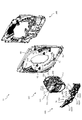
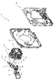
次いで、図5から図7を参照して、遊技盤13の概略構成について説明する。図5は、遊技盤13の正面斜視図であり、図6は、遊技盤13の分解正面斜視図であり、図7は、遊技盤13の分解背面斜視図である。   Next, a schematic configuration of the game board 13 will be described with reference to FIGS. 5 is a front perspective view of the game board 13, FIG. 6 is an exploded front perspective view of the game board 13, and FIG. 7 is an exploded rear perspective view of the game board 13.

図5から図7に示すように、遊技盤13は、透明な可撓性材料の樹脂からなるベース板60の中央部の開口60aの内部に配設される可動入球役物装置300と、その可動入球役物装置300の重力方向下側に位置すると共にベース板60に配設される入賞口ユニット600と、ベース板60の背面側に配置される照射ユニット900と、を主に備える。   As shown in FIGS. 5 to 7, the game board 13 includes a movable entrance ball accessory device 300 disposed inside an opening 60 a at the center of a base plate 60 made of a resin of a transparent flexible material, It is mainly provided with a winning opening unit 600 that is positioned on the lower side in the gravitational direction of the movable incoming ball accessory device 300 and disposed on the base plate 60, and an irradiation unit 900 that is disposed on the back side of the base plate 60. .

可動入球役物装置300は、正面視におけるベース板60の中央部に貫通形成される開口60aの内部に正面側から挿入される。可動入球役物装置300は、開口60aよりも大きい外形の縁部を備え、その縁部がベース板60の正面と当接して配設される。これにより、可動入球役物装置300をベース板60に対して前後方向に位置決めして配設できる。なお、可動入球役物装置300の詳細な説明は後述する。   The movable ball accessory device 300 is inserted from the front side into an opening 60a formed through the central portion of the base plate 60 in a front view. The movable entrance ball accessory apparatus 300 includes an edge portion having an outer shape larger than the opening 60 a, and the edge portion is disposed in contact with the front surface of the base plate 60. Thus, the movable ball accessory device 300 can be positioned and disposed with respect to the base plate 60 in the front-rear direction. The detailed description of the movable ball accessory device 300 will be described later.

入賞口ユニット600は、上述した各始動入賞口26,27,28を備えるユニットであり、可動入球役物装置300の重力方向下側に位置し、ベース板60に配設される。なお、入賞口ユニット600の詳細な説明は後述する。   The winning a prize opening unit 600 is a unit that includes the above-described starting winning award openings 26, 27, and 28, and is located on the lower side in the gravitational direction of the movable winning ball accessory 300 and is disposed on the base plate 60. The detailed description of the prize opening unit 600 will be described later.

照射ユニット900は、正面視略矩形の枠状態から形成されており、その外形が、ベース板60の正面視における外形よりも小さく形成される。これにより、ベース板60を介して照射ユニット900を遊技者が直接視認することを不能とできる。   The irradiation unit 900 is formed from a substantially rectangular frame state when viewed from the front, and its outer shape is smaller than the outer shape of the base plate 60 when viewed from the front. This makes it impossible for the player to directly view the irradiation unit 900 via the base plate 60.

また、照射ユニット900の内部には、LEDを備えた基盤(図示せず)が配設されており、LEDから照射される光が正面側(遊技者側)に照射される。上述したように、ベース板60は、透明な可撓性材料の樹脂で形成されるので、照射ユニット900のLEDから照射される光をベース板60を介して遊技者側に照射できる。   Moreover, the board | substrate (not shown) provided with LED is arrange | positioned inside the irradiation unit 900, and the light irradiated from LED is irradiated to the front side (player side). As described above, since the base plate 60 is formed of a resin of a transparent flexible material, the player side can be irradiated with light emitted from the LEDs of the irradiation unit 900 via the base plate 60.

次いで、図8から図90を参照して、可動入球役物装置300、入賞口ユニット600の詳細構成を説明する。まず、図8から図80を参照して、可動入球役物装置300について説明する。   Next, with reference to FIG. 8 to FIG. 90, the detailed configurations of the movable ball accessory device 300 and the winning opening unit 600 will be described. First, with reference to FIGS. 8 to 80, the movable ball accessory device 300 will be described.

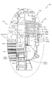
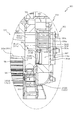
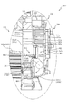
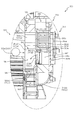
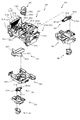
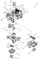
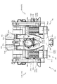
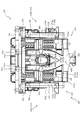
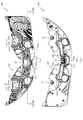
初めに、図8から図13を参照して、可動入球役物装置300の全体構成について説明する。図8は、可動入球役物装置300の正面図であり、図9は、可動入球役物装置300の背面図である。図10は、可動入球役物装置300の正面斜視図であり、図11は、可動入球役物装置300の背面斜視図である。図12は、可動入球役物装置300の分解正面斜視図であり、図13は、可動入球役物装置300の分解背面斜視図である。   First, with reference to FIGS. 8 to 13, the overall configuration of the movable ball accessory device 300 will be described. FIG. 8 is a front view of the movable incoming ball accessory device 300, and FIG. 9 is a rear view of the movable incoming ball accessory device 300. FIG. 10 is a front perspective view of the movable incoming ball accessory device 300, and FIG. 11 is a rear perspective view of the movable incoming ball accessory device 300. FIG. 12 is an exploded front perspective view of the movable incoming ball accessory apparatus 300, and FIG. 13 is an exploded rear perspective view of the movable incoming ball accessory apparatus 300.

図8から図13に示すように、可動入球役物装置300は、正面視略矩形の枠状態に形成されるセンターフレーム310と、そのセンターフレーム310の背面側の重力方向上側に重ね合される中間部材330と、その中間部材330の背面側に配設される後方部材350と、センターフレーム310の背面側に配設される可変ユニット360と、その可変ユニット360及び後方部材350の背面側を覆う様態で配設される背面ベース390と、その背面ベース390の背面側に配設される制御基板410とを主に備えて形成される。   As shown in FIGS. 8 to 13, the movable ball accessory device 300 is superimposed on the center frame 310 formed in a substantially rectangular frame state in front view and the upper side in the gravity direction on the back side of the center frame 310. Intermediate member 330, rear member 350 disposed on the back side of intermediate member 330, variable unit 360 disposed on the back side of center frame 310, and back side of variable unit 360 and rear member 350 And a control board 410 provided on the back side of the back surface base 390.

可動入球役物装置300は、枠状態のセンターフレーム310の内側を通じて背面側に配設される中間部材330、後方部材350及び可変ユニット360を遊技者が視認可能とされる(図8参照)。   In the movable ball accessory device 300, the player can visually recognize the intermediate member 330, the rear member 350, and the variable unit 360 disposed on the back side through the inside of the center frame 310 in a frame state (see FIG. 8). .

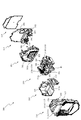
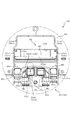
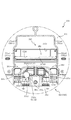
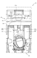
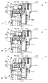
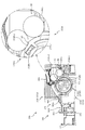
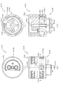
次に、図14及び図15を参照して、センターフレーム310の詳細な構成を説明する。図14は、センターフレーム310の分解正面斜視図であり、図15は、センターフレーム310の分解背面斜視図である。   Next, a detailed configuration of the center frame 310 will be described with reference to FIGS. 14 and 15. FIG. 14 is an exploded front perspective view of the center frame 310, and FIG. 15 is an exploded rear perspective view of the center frame 310.

図14及び図15に示すように、センターフレーム310は、正面視枠状に形成される枠体311と、枠体311の正面側の重力方向上側に回転可能に軸支される羽部312と、枠体311の正面側を覆う様態で配設され枠体311との間に羽部312を介設する上部正面カバー313と、羽部312を回転させるための駆動力を発生させるソレノイド317と、そのソレノイド317の駆動力を羽部312に伝達する軸部315と、ソレノイド317を収容する背面カバー316と、その背面カバー316の背面側に覆設されてソレノイド317が背面カバー316から抜け出ることを抑制する通気カバー318とを主に備えて形成される。   As shown in FIGS. 14 and 15, the center frame 310 includes a frame body 311 that is formed in a frame shape when viewed from the front, and a wing portion 312 that is rotatably supported on the upper side in the gravity direction on the front side of the frame body 311. An upper front cover 313 that is arranged in a manner to cover the front side of the frame 311 and has a wing 312 interposed between the frame 311 and a solenoid 317 that generates a driving force for rotating the wing 312; The shaft portion 315 that transmits the driving force of the solenoid 317 to the wing portion 312, the back cover 316 that accommodates the solenoid 317, and the solenoid 317 comes out of the back cover 316 so as to cover the back side of the back cover 316. It is mainly provided with a ventilation cover 318 for suppressing the above.

枠体311は、正面視枠状態に形成されると共に、重力方向上側の正面に背面側に向かって凹設される凹部311aと、その凹部311aの重力方向下側の縁部に配設される一対の第1センサ311bと、その一対の第1センサ311bの間に形成される上方傾斜部311cと、重力方向下側の内周面に形成される下降傾斜部311dと、その下降傾斜部311dの両端部に遊技球が通過可能な大きさに開口される回収孔311eと、凹部311aに正面側から背面側に亘って貫通形成される貫通孔311fとを主に備えて形成される。   The frame body 311 is formed in a front-view frame state, and is disposed on a recess 311a that is recessed toward the back side on the front surface in the gravity direction upper side, and an edge portion on the lower side in the gravity direction of the recess 311a. A pair of first sensors 311b, an upper inclined portion 311c formed between the pair of first sensors 311b, a downward inclined portion 311d formed on the inner peripheral surface on the lower side in the gravity direction, and a downward inclined portion 311d A recovery hole 311e that is opened to a size that allows a game ball to pass therethrough at both ends thereof, and a through hole 311f that is formed through the recess 311a from the front side to the back side.

凹部311aは、後述する上部正面カバー313との対向間に遊技球が通過可能な間隙を形成するための凹みであり、凹設寸法が遊技球の直径よりも大きく設定される。また、凹部311aは、正面視において左右方向(図8左右方向)両端に向かうに従って重力方向下側(図8下側)に湾曲する三日月形状に形成される。これにより、凹部311aの縁部に流下した遊技球を、その湾曲形状に沿って枠体311の外側に転動させつつ流下させることができる。   The recess 311a is a recess for forming a gap through which a game ball can pass between facing the upper front cover 313, which will be described later, and the recess dimension is set larger than the diameter of the game ball. Moreover, the recessed part 311a is formed in the crescent moon shape which curves to a gravity direction lower side (FIG. 8 lower side) as it goes to the left-right direction (FIG. 8 left-right direction) both ends in front view. Thereby, the game ball that has flowed down to the edge of the recess 311a can flow down while rolling to the outside of the frame 311 along the curved shape.

上方傾斜部311cは、枠体311の左右方向中央部に位置すると共に、凹部311aの他側の縁部(凹部311aの正面と枠体311の正面とを連結する面)に形成される。上方傾斜部311cは、枠体311の中央部から左右方向両端部に向かうに従って重力方向下側に傾斜して形成される。これにより、凹部311a(枠体311)と上部正面カバー313との対向間に遊技球が送球されると、送球された遊技球は、上方傾斜部311cの上面を重力により転動して、上方傾斜部311cの終端(左右の両端部)から落下する。   The upper inclined portion 311c is located at the central portion in the left-right direction of the frame body 311 and is formed on the other edge of the recess 311a (the surface connecting the front surface of the recess 311a and the front surface of the frame body 311). The upward inclined portion 311c is formed to be inclined downward in the gravitational direction as it goes from the central portion of the frame body 311 to both ends in the left-right direction. As a result, when a game ball is sent between the recess 311a (frame body 311) and the upper front cover 313, the sent game ball rolls on the upper surface of the upper inclined portion 311c due to gravity, and moves upward. It falls from the end (left and right ends) of the inclined portion 311c.

第1センサ311bは、内部に遊技球が通過可能な大きさの開口の第1検出孔311b1が形成される。第1センサ311bは、第1検出孔311b1の内部に遊技球を通過することで遊技球の通過を検知できる。   The first sensor 311b is formed with a first detection hole 311b1 having an opening that allows a game ball to pass therethrough. The first sensor 311b can detect the passing of the game ball by passing the game ball inside the first detection hole 311b1.

第1センサ311bは、上方傾斜部311cの左右方向両端部の外側に第1検出孔311b1が重力方向に開口する様態で配置されると共に、上方傾斜部311cの下降傾斜端よりも下方に位置して配設される。よって、上述したように、上方傾斜部311cを転動する遊技球は、上方傾斜部311cの終端まで転動して上方傾斜部311cから落下すると、第1センサ311bの第1検出孔311b1の内部を通過する。これにより、第1センサ311bで凹部311aと上部正面カバー313との対向間に送球された遊技球を検出できる。   The first sensor 311b is disposed outside the both ends in the left-right direction of the upper inclined portion 311c so that the first detection holes 311b1 open in the gravitational direction, and is positioned below the lower inclined end of the upper inclined portion 311c. Arranged. Therefore, as described above, when the game ball rolling on the upper inclined portion 311c rolls to the end of the upper inclined portion 311c and falls from the upper inclined portion 311c, the inside of the first detection hole 311b1 of the first sensor 311b. Pass through. Thereby, the game ball sent between the confrontation of the recessed part 311a and the upper front cover 313 by the 1st sensor 311b is detectable.

貫通孔311fは、内部に後述する軸部315の回転軸315aが挿通される孔であり、凹部311aの他側に正面から背面に亘って貫通されると共に、その内径が回転軸315aの外径よりも大きく形成される。   The through-hole 311f is a hole into which a rotation shaft 315a of a shaft portion 315 described later is inserted, and is penetrated from the front to the back on the other side of the recess 311a, and the inner diameter thereof is the outer diameter of the rotation shaft 315a. Is formed larger.

下降傾斜部311dは、後述する可変ユニット360の上部を送球される遊技球が、可変ユニット360の正面から落下した際に、その遊技球を受け止めて回収孔311eに送球する面であり、センターフレーム310の他側の内周面に形成される。下降傾斜部311dは、左右方向略中央位置から外側に向かうに従って重力方向下側に傾斜して形成される。よって、下降傾斜部311dの上部に送球された遊技球をその傾斜に沿って下降傾斜部311dの終端位置まで転動させることができる。   The descending inclined portion 311d is a surface that receives a game ball sent from the front of the variable unit 360 and sends it to the collection hole 311e when a game ball sent from the upper part of the variable unit 360, which will be described later, falls from the front of the variable unit 360. 310 is formed on the inner peripheral surface on the other side. The descending inclined portion 311d is formed to be inclined downward in the gravitational direction from the substantially central position in the left-right direction toward the outside. Therefore, the game ball sent to the upper part of the downward inclination part 311d can be rolled along the inclination to the terminal position of the downward inclination part 311d.

回収孔311eは、上述したように下降傾斜部311dに送球される遊技球が次に送球される孔であり、球の外径よりも大きい開口に形成されると共に、下降傾斜部311dの左右方向両端に形成される。よって、上述したように、下降傾斜部311dの上部を転動する遊技球は、下降傾斜部311dの終端まで転動して下降傾斜部311dから落下すると、回収孔311eの内部に送球される。   As described above, the recovery hole 311e is a hole through which the game ball sent to the descending inclined portion 311d is next sent, and is formed in an opening larger than the outer diameter of the ball, and the horizontal direction of the descending inclined portion 311d Formed at both ends. Therefore, as described above, when the game ball rolling on the upper part of the descending inclined part 311d rolls to the end of the descending inclined part 311d and falls from the descending inclined part 311d, it is sent into the collection hole 311e.

羽部312は、正面視略三角形に形成され、その厚みが遊技球の直径と略同一に設定される。また、羽部312は、背面側の他側(重力方向下側)に正面側に向かって円形に凹設される軸支孔312aが形成される。   The wing 312 is formed in a substantially triangular shape when viewed from the front, and its thickness is set to be substantially the same as the diameter of the game ball. Further, the wing portion 312 is formed with a shaft support hole 312a which is recessed in a circular shape toward the front side on the other side (lower side in the direction of gravity) on the back side.

軸支孔312aは、後述する軸部315の回転軸315aが内嵌される孔であり、回転軸315aの外径と略同一もしくは小さい内径に形成される。これにより、軸部315の回転軸315aが回転されると、軸支孔312aを軸として羽部312を回転変位させることができる。なお、羽部312の動作についての詳しい説明は後述する。   The shaft support hole 312a is a hole into which a rotation shaft 315a of a shaft portion 315 described later is fitted, and is formed to have an inner diameter substantially the same as or smaller than the outer diameter of the rotation shaft 315a. Accordingly, when the rotation shaft 315a of the shaft portion 315 is rotated, the wing portion 312 can be rotationally displaced about the shaft support hole 312a. A detailed description of the operation of the wing part 312 will be given later.

上部正面カバー313は、枠体311の正面側に遊技球の流下経路を形成するための板であり、枠体311の凹部311aの正面と遊技球の直径よりも大きい隙間を隔てて配設される。これにより、凹部311aと上部正面カバー313との対向間に遊技球が流下可能な隙間が形成される。また、上部正面カバー313は、透明な板状体で形成されており、遊技者から凹部311aと上部正面カバー313との対向間を流下する遊技球を視認可能とできる。   The upper front cover 313 is a plate for forming a flow path for the game ball on the front side of the frame 311 and is disposed with a gap larger than the front of the recess 311a of the frame 311 and the diameter of the game ball. The Thus, a gap is formed between the concave portion 311a and the upper front cover 313 so that the game ball can flow down. Further, the upper front cover 313 is formed of a transparent plate-like body, and it is possible to visually recognize the game ball flowing down between the opposing portions of the recess 311a and the upper front cover 313.

上部正面カバー313は、一側(重力方向上側)が湾曲する半円弧状に形成されると共に、一側端部の背面側に突出する膨出部313aを備える。   The upper front cover 313 is formed in a semicircular arc shape in which one side (the upper side in the direction of gravity) is curved, and includes a bulging portion 313a that protrudes to the back side of one end portion.

膨出部313aは、上部正面カバー313の重力方向上方から流下する遊技球が、凹部311aと上部正面カバー313との対向間に侵入することを防止するための突出部であり、一対に配設される羽部312の対向間の上部に形成される。また、羽部312が第1状態(羽部312が回転変位されず、先端部A1を軸支孔312aの重力方向上側に位置する状態)に位置する際には、羽部312と膨出部313aとの隙間が遊技球の直径よりも小さく設定されており、遊技盤13の正面側を流下する遊技球が凹部311aと上部正面カバー313との対向間に侵入できない状態とされる(図17(a)参照)。   The bulging portion 313a is a protruding portion for preventing a game ball flowing down from above the upper front cover 313 in the direction of gravity from entering between the opposing portions of the concave portion 311a and the upper front cover 313. It is formed in the upper part between the opposing wings 312. When the wing 312 is positioned in the first state (the wing 312 is not rotationally displaced and the tip A1 is positioned on the upper side in the gravity direction of the shaft support hole 312a), the wing 312 and the bulging portion The gap with 313a is set to be smaller than the diameter of the game ball, and the game ball flowing down the front side of the game board 13 cannot enter between the recess 311a and the upper front cover 313 (FIG. 17). (See (a)).

ソレノイド317は、羽部312に駆動力を付与する駆動手段であり、ピストン変位する軸部317aと、その軸部317aの重力方向下側に形成される伝達部317bとを主に備えて形成される。   The solenoid 317 is a driving unit that applies a driving force to the wing part 312 and is mainly provided with a shaft part 317a that displaces the piston and a transmission part 317b that is formed below the shaft part 317a in the gravity direction. The

軸部317aは、円柱形状に形成されると共に、一側がソレノイド317の内部に挿通される。軸部317aは、その軸方向が重力方向と平行に配設されており、ソレノイド317に電力が付与されると、重力方向上側に変位してソレノイド317の内部に引き込まれる。即ち、軸部317aは、重力方向にピストン運動することができる。   The shaft portion 317 a is formed in a cylindrical shape, and one side is inserted into the solenoid 317. The shaft portion 317 a is disposed so that its axial direction is parallel to the gravitational direction. When electric power is applied to the solenoid 317, the shaft portion 317 a is displaced upward in the gravitational direction and drawn into the solenoid 317. That is, the shaft portion 317a can perform a piston motion in the direction of gravity.

伝達部317bは、軸部317aの他側から内部に開口317b1を有したD字状に突出して形成される。伝達部317bの開口317b1は、正面側から背面側に亘って開口して形成されており、内部に後述する可変軸315bが挿入される。よって、軸部317aが重力方向にピストン運動すると、伝達部317bに挿入された可変軸315bが重力方向に変位される。   The transmission portion 317b is formed to project in a D shape having an opening 317b1 from the other side of the shaft portion 317a. An opening 317b1 of the transmission portion 317b is formed to open from the front side to the back side, and a variable shaft 315b described later is inserted therein. Therefore, when the shaft portion 317a is piston-moved in the gravity direction, the variable shaft 315b inserted in the transmission portion 317b is displaced in the gravity direction.

軸部315は、ソレノイド317の駆動力を羽部312に伝達する軸であり、正面側の一端に配設されて羽部312に連結される回転軸315aと、背面側の一端に配設されてソレノイド317に係合される可変軸315bと、回転軸315a及び可変軸315bを連結する連結部315cとを主に備えて形成される。   The shaft portion 315 is a shaft that transmits the driving force of the solenoid 317 to the wing portion 312. The shaft portion 315 is disposed at one end on the front side and is connected to the wing portion 312. The shaft portion 315 is disposed on one end on the back side. Thus, a variable shaft 315b engaged with the solenoid 317 and a connecting portion 315c for connecting the rotating shaft 315a and the variable shaft 315b are mainly provided.

回転軸315aは、上述したように、羽部312を回転させる駆動力を伝達する軸であり、正面側の一端が枠体311の貫通孔311fの背面側から挿入されて正面側に突出されると共に、枠体311の正面側から突出した端部に羽部312の軸支孔312aが外嵌される。   As described above, the rotation shaft 315a is a shaft that transmits a driving force for rotating the wing 312. One end of the front side is inserted from the back side of the through hole 311f of the frame body 311 and protrudes to the front side. At the same time, the shaft support hole 312a of the wing 312 is fitted on the end protruding from the front side of the frame 311.

可変軸315bは、上述したように背面側の端部がソレノイド317の伝達部317bに挿入されており、ソレノイド317の駆動により変位される。   As described above, the variable shaft 315b has its rear end inserted into the transmission portion 317b of the solenoid 317, and is displaced by driving the solenoid 317.

連結部315cは、回転軸315aと可変軸315bとを連結する連結部分であり、回転軸315aの背面側の端部と可変軸315bの正面側の端部とが連結される。回転軸315aと可変軸315bとは、互いの軸が平行となる様態で連結される。即ち、回転軸315aと可変軸315bとは、偏心する位置で連結部315cにより連結される。これにより、可変軸315bが重力方向に変位されると、その変位が連結部315cにより回転軸315aに伝達され、回転軸315aが回転変位する。その結果、羽部312を回転変位させることができる。   The connecting portion 315c is a connecting portion that connects the rotating shaft 315a and the variable shaft 315b, and connects the end portion on the back side of the rotating shaft 315a and the end portion on the front side of the variable shaft 315b. The rotating shaft 315a and the variable shaft 315b are connected in such a manner that their axes are parallel to each other. That is, the rotating shaft 315a and the variable shaft 315b are connected by the connecting portion 315c at an eccentric position. Thereby, when the variable shaft 315b is displaced in the direction of gravity, the displacement is transmitted to the rotating shaft 315a by the connecting portion 315c, and the rotating shaft 315a is rotationally displaced. As a result, the wing part 312 can be rotationally displaced.

背面カバー316は、内部にソレノイド317を配設するための板であり、枠体311の重力方向上側の一側の背面を覆設する様態で配設されると共に、背面側にソレノイド317を配設する凹設部316aと、その凹設部316aの重力方向下側に開口316bと、が形成される。   The back cover 316 is a plate for disposing the solenoid 317 therein. The back cover 316 is disposed so as to cover the back surface on the one side of the frame body 311 in the gravity direction, and the solenoid 317 is disposed on the back surface side. A recessed portion 316a is provided, and an opening 316b is formed below the recessed portion 316a in the direction of gravity.

凹設部316aは、内部にソレノイド317を配設するための凹みであり、ソレノイド317と対向する位置に凹設される。凹設部316aの凹設深さは、ソレノイド317の前後方向の厚み寸法と略同一に設定されており、背面カバー316の背面側とソレノイド317の背面側とが略一致する位置に配設される。よって、背面カバー316の背面側に板状体から形成される通気カバー318が覆設されることで、背面カバー316からソレノイド317が脱落不能とされる。   The recessed portion 316 a is a recess for disposing the solenoid 317 therein, and is recessed at a position facing the solenoid 317. The depth of the recessed portion 316a is set to be approximately the same as the thickness dimension of the solenoid 317 in the front-rear direction, and is disposed at a position where the back side of the back cover 316 and the back side of the solenoid 317 are substantially coincident. The Therefore, the solenoid cover 318 cannot be removed from the back cover 316 by covering the back cover 316 with the ventilation cover 318 formed of a plate-like body.

開口316bは、ソレノイド317の伝達部317bに軸部315の可変軸315bを係合させるための開口であり、可変軸315bの変位領域よりも大きい開口に形成される。これにより、背面カバー316の背面側に配設されるソレノイド317の駆動力を軸部315に伝達することができる。   The opening 316b is an opening for engaging the variable shaft 315b of the shaft portion 315 with the transmission portion 317b of the solenoid 317, and is formed in an opening larger than the displacement region of the variable shaft 315b. Thereby, the driving force of the solenoid 317 disposed on the back side of the back cover 316 can be transmitted to the shaft portion 315.

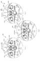
次いで、図16及び図17を参照して、羽部312の変位動作について説明する。図16の(a)から(c)は、センターフレーム310の部分拡大背面図であり、図17の(a)から(c)は、センターフレーム310の部分拡大正面図である。   Next, the displacement operation of the wing part 312 will be described with reference to FIGS. 16 and 17. 16A to 16C are partially enlarged rear views of the center frame 310, and FIGS. 17A to 17C are partially enlarged front views of the center frame 310. FIG.

なお、図16(a)及び図17(a)は、羽部312の変位前の第1状態が、図16(c)及び図17(c)は、羽部312の変位後の第3状態が、図16(b)及び図17(b)は、第1状態から第3状態への変位途中の中間位置における状態の第2状態が、それぞれ図示される。また、図17では、羽部312の軸支孔312aと反対側の端部を先端部A1として説明する。   16A and 17A show the first state before the wing 312 is displaced, and FIGS. 16C and 17C show the third state after the wing 312 is displaced. However, FIG. 16B and FIG. 17B illustrate the second state of the intermediate position in the middle of the displacement from the first state to the third state, respectively. Moreover, in FIG. 17, the edge part on the opposite side to the axial support hole 312a of the wing | blade part 312 is demonstrated as front-end | tip part A1.

さらに、図16(a)から図16(c)では、通気カバー318が、図17(a)から図17(c)では、上部正面カバー313が、それぞれ透明視された状態が図示される。また、図16及び図17では、回転軸315aが破線で図示される。   Further, in FIGS. 16A to 16C, the ventilation cover 318 and the upper front cover 313 are transparently illustrated in FIGS. 17A to 17C, respectively. Moreover, in FIG.16 and FIG.17, the rotating shaft 315a is illustrated with a broken line.

図16(a)及び図17(a)に示すように、第1状態ではソレノイド317の軸部317aが重力方向下側に突出した状態で配設される。これにより、伝達部317bの開口317b1に挿通される可変軸315bが回転軸315aよりも重力方向下側に位置した状態とされる。この場合、回転軸315aを外嵌する羽部312の先端部A1は、軸支孔312a(回転軸315a)の重力方向上側(図17(a)上側)、且つ、一対の羽部312の対向間の内側に位置する。   As shown in FIGS. 16A and 17A, in the first state, the shaft portion 317a of the solenoid 317 is disposed in a state of protruding downward in the gravity direction. As a result, the variable shaft 315b inserted through the opening 317b1 of the transmission portion 317b is in a state of being located below the rotation shaft 315a in the gravity direction. In this case, the tip A1 of the wing part 312 that externally fits the rotating shaft 315a is above the shaft support hole 312a (rotating shaft 315a) in the gravitational direction (upper side in FIG. 17A) and is opposed to the pair of wing parts 312. Located inside.

図16(a)及び図17(a)に示す状態から、ソレノイド317に電力が付与されて軸部317aが重力方向上方に変位すると、図16(b)及び図17(b)に示す第2状態とされる。   When power is applied to the solenoid 317 from the state shown in FIGS. 16 (a) and 17 (a) and the shaft portion 317a is displaced upward in the direction of gravity, the second state shown in FIGS. 16 (b) and 17 (b). State.

図16(b)及び図17(b)に示すように、第2状態では、軸部317aが重力方向上側に変位してソレノイド317の内部に収容される分、軸部315の可変軸315bが、回転軸315aの軸を中心に回転しつつ重力方向上側に変位される。可変軸315bが回転変位されると、その回転変位が連結部315cを介して回転軸315aに伝達されて回転軸315aが回転される。これにより、羽部312が軸支孔312aを軸に回転変位される。   As shown in FIGS. 16B and 17B, in the second state, the shaft 317a is displaced upward in the direction of gravity and accommodated in the solenoid 317, so that the variable shaft 315b of the shaft 315 is accommodated. , While being rotated about the axis of the rotation shaft 315a, it is displaced upward in the gravitational direction. When the variable shaft 315b is rotationally displaced, the rotational displacement is transmitted to the rotational shaft 315a via the connecting portion 315c, and the rotational shaft 315a is rotated. Thereby, the wing | blade part 312 is rotationally displaced centering on the axial support hole 312a.

第2状態では、羽部312の先端部A1は、一対の羽部312の対向間の外側に位置すると共に、先端部A1と上部正面カバー313の膨出部313aとの隙間が遊技球の外径よりも大きくされる。即ち、第2状態では、枠体311の凹部311aと上部正面カバーとの対向間に重力方向上側から流下される遊技球を流入可能とされる。   In the second state, the tip portion A1 of the wing portion 312 is located on the outer side between the facing of the pair of wing portions 312 and the gap between the tip portion A1 and the bulging portion 313a of the upper front cover 313 is outside the game ball. It is made larger than the diameter. That is, in the second state, it is possible to allow a game ball that flows down from the upper side in the direction of gravity to flow between the recess 311a of the frame 311 and the upper front cover.

なお、第2状態とは、第1状態から第3状態への変位における中間位置である。即ち、羽部312の変位は、上述した第1状態の位置と後述する第3状態の位置とを一連の動作として行われる。   The second state is an intermediate position in the displacement from the first state to the third state. That is, the displacement of the wing 312 is performed as a series of operations of the position of the first state described above and the position of the third state described later.

図16(b)及び図17(b)に示す状態から、ソレノイド317に電力が付与され続けて、軸部317aが重力方向上側にさらに変位すると、図16(c)及び図17(c)に示す第3状態とされる。   When the power is continuously applied to the solenoid 317 from the state shown in FIGS. 16B and 17B and the shaft portion 317a is further displaced upward in the gravitational direction, the state shown in FIGS. 16C and 17C is obtained. The third state is shown.

図16(b)及び図17(b)に示すように、第3状態では、上述した第2状態よりもさらに軸部317aが重力方向上側に変位してソレノイド317の内部に収容される。これにより、軸部315の可変軸315bが、回転軸315aの軸を中心にさらに回転しつつ重力方向上側に変位される。可変軸315bが回転変位されると、上述した第1状態から第2状態への変位と同様に、可変軸315bの回転変位が連結部315cを介して回転軸315aに伝達されて回転軸315aが更に回転される。従って、羽部312が軸支孔312aを軸に第2状態よりもさらに回転変位される。   As shown in FIGS. 16B and 17B, in the third state, the shaft portion 317a is displaced further upward in the gravitational direction than the second state described above and is accommodated in the solenoid 317. Thereby, the variable shaft 315b of the shaft portion 315 is displaced upward in the gravitational direction while further rotating around the axis of the rotation shaft 315a. When the variable shaft 315b is rotationally displaced, similarly to the displacement from the first state to the second state described above, the rotational displacement of the variable shaft 315b is transmitted to the rotational shaft 315a via the connecting portion 315c, and the rotational shaft 315a is transmitted. It is further rotated. Therefore, the wing portion 312 is further rotationally displaced about the shaft support hole 312a as compared with the second state.

第3状態では、羽部312の先端部A1は、一対の羽部312の対向間の外側に位置すると共に、先端部A1と軸支孔312a(回転軸315a)とを結ぶ仮想線S1が、重力方向に対して略45度左右方向外側に傾斜する状態とされる。これにより、遊技盤13の上方を流下する遊技球を羽部312で受け止め可能な領域が拡大されるので、枠体311の凹部311aと上部正面カバー313との対向間に遊技球を流入させやすくできる。   In the third state, the tip end portion A1 of the wing portion 312 is located on the outer side between the facing of the pair of wing portions 312, and an imaginary line S1 connecting the tip portion A1 and the shaft support hole 312a (rotating shaft 315a) is It is in a state of tilting about 45 degrees outward in the left-right direction with respect to the direction of gravity. As a result, the area where the wings 312 can receive the game balls flowing down the game board 13 is enlarged, so that the game balls can easily flow between the recess 311a of the frame 311 and the upper front cover 313. it can.

次に、図18を参照して、第1状態および第3状態における遊技盤13を流下する遊技球について説明する。図18(a)は、第1状態におけるセンターフレーム310の部分拡大正面図であり、図18(b)は、第3状態におけるセンターフレーム310の部分拡大正面図である。   Next, with reference to FIG. 18, the game ball flowing down the game board 13 in the first state and the third state will be described. FIG. 18A is a partially enlarged front view of the center frame 310 in the first state, and FIG. 18B is a partially enlarged front view of the center frame 310 in the third state.

図18(a)に示すように、第1状態では、羽部312の先端部A1と上部正面カバー313の膨出部313aとの隙間が遊技球の直径よりも小さくされるので、枠体311の凹部311aと上部正面カバー313との対向間に遊技球が流入不可能とされる。   As shown in FIG. 18 (a), in the first state, the gap between the tip A1 of the wing 312 and the bulging portion 313a of the upper front cover 313 is made smaller than the diameter of the game ball. The game ball cannot flow between the recess 311a and the upper front cover 313.

よって、センターフレーム310の上方から流下する遊技球は、枠体311の凹部311aと上部正面カバー313との対向間に流入することなく、センターフレーム310(可動入球役物装置300)の左右方向両側を流下する。   Therefore, the game ball flowing down from above the center frame 310 does not flow between the recess 311a of the frame 311 and the upper front cover 313, and the center frame 310 (movable ball accessory device 300) in the left-right direction. Flow down on both sides.

一方、第3状態では、上述したように羽部312の先端部A1と軸支孔312aとを結ぶ仮想線S1は、重力方向に対して略45度傾斜する様態とされる。よって、図18(b)に示すように、枠体311の凹部311aと上部正面カバー313との対向間に遊技球が流入可能とされる。   On the other hand, in the third state, as described above, the imaginary line S1 connecting the tip A1 of the wing 312 and the shaft support hole 312a is inclined by approximately 45 degrees with respect to the direction of gravity. Therefore, as shown in FIG. 18B, the game ball can flow between the recess 311 a of the frame 311 and the upper front cover 313.

従って、センターフレーム310の上方から流下して、羽部312の上方に衝突する遊技球は、羽部312によって枠体311の凹部311aと上部正面カバー313との対向間に転動して送球される。   Therefore, the game ball that flows down from the upper side of the center frame 310 and collides with the upper side of the wing part 312 is rolled and sent by the wing part 312 between the recess 311a of the frame 311 and the upper front cover 313. The

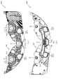
次いで、図19及び図20を参照して、中間部材330の詳細な構成について説明する。図19(a)は、中間部材330の正面図であり、図19(b)は、中間部材330の背面図であり、図19(c)は、図19(a)のXIXc−XIXc線における中間部材330の断面図である。図20(a)は、中間部材330の分解正面斜視図であり、図20(b)は、中間部材330の分解背面斜視図である。   Next, the detailed configuration of the intermediate member 330 will be described with reference to FIGS. 19 and 20. 19A is a front view of the intermediate member 330, FIG. 19B is a rear view of the intermediate member 330, and FIG. 19C is a cross-sectional view taken along line XIXc-XIXc in FIG. 4 is a cross-sectional view of an intermediate member 330. FIG. 20A is an exploded front perspective view of the intermediate member 330, and FIG. 20B is an exploded rear perspective view of the intermediate member 330. FIG.

図19及び図20に示すように、中間部材330は、正面視略矩形に形成される本体部331と、その本体部331の左右方向外側の両側に配設され本体部331の内側を照射する装飾基盤332とを主に備えて形成される。   As shown in FIGS. 19 and 20, the intermediate member 330 is disposed on both sides of the main body portion 331 formed in a substantially rectangular shape in front view and the left and right outer sides of the main body portion 331 and irradiates the inside of the main body portion 331. The decorative base 332 is mainly provided and formed.

本体部331は、センターフレーム310の枠体311の凹部311aと上部正面カバー313との対向間に送球された遊技球を第1センサ311bの重力方向下側で拾って背面側に送球するための板であり、正面側の略中央位置から突出してその先端が第1検出孔311b1(第1センサ311b)の重力方向下側に配置される受部331aと、その受部331aの重力方向下側に位置して、受部331aから送球される遊技球を複数の流路に案内する案内部331bとを主に備えて形成される。   The main body portion 331 picks up a game ball sent between the concave portion 311a of the frame body 311 of the center frame 310 and the upper front cover 313 at the lower side in the gravity direction of the first sensor 311b and sends it to the back side. A receiving portion 331a that protrudes from a substantially central position on the front side and whose tip is disposed below the first detection hole 311b1 (first sensor 311b) in the gravitational direction; and the lower side in the gravitational direction of the receiving portion 331a And a guide portion 331b for guiding a game ball sent from the receiving portion 331a to a plurality of flow paths.

また、本体部331は、透明な可撓性材料から形成される。これにより、本体部331の左右方向外側に配設する装飾基盤332から照射される光を本体部331の内側に照射することができる。   Moreover, the main-body part 331 is formed from a transparent flexible material. Thereby, the light irradiated from the decoration base 332 arrange | positioned in the left-right direction outer side of the main-body part 331 can be irradiated to the inner side of the main-body part 331.

受部331aは、正面視において重力方向上側(図19(a)上下方向上側)が開放する断面略U字状に形成される。受部331aの正面側の突出先端は、センターフレーム310の枠体311の開口内部に挿入されると共に、枠体311の第1検出孔311b1(第1センサ311b)の重力方向下側に位置して配設される。これにより、上述したように、枠体311(センターフレーム310)の第1検出孔311b1を通過する遊技球を受部331aの内面(U字状の内側部分)に落下させることできる。   The receiving portion 331a is formed in a substantially U-shaped cross section in which the upper side in the gravitational direction (the upper side in the vertical direction in FIG. 19A) is open when viewed from the front. The protruding front end of the receiving portion 331a is inserted into the opening of the frame 311 of the center frame 310, and is positioned below the first detection hole 311b1 (first sensor 311b) in the gravity direction of the frame 311. Arranged. Thereby, as described above, the game ball passing through the first detection hole 311b1 of the frame 311 (center frame 310) can be dropped onto the inner surface (U-shaped inner portion) of the receiving portion 331a.

また、受部331aは、重力方向下側の底面が正面側から背面側に向かうに従って下降傾斜して形成される(図19(c)参照)。これにより、受部331aに落下した遊技球を、その下降傾斜に沿って転動させて本体部331の背面側に送球することができる。   Further, the receiving portion 331a is formed so as to be inclined downward as the bottom surface on the lower side in the direction of gravity moves from the front side to the back side (see FIG. 19C). Thereby, the game ball dropped on the receiving portion 331a can be rolled along the descending slope and sent to the back side of the main body portion 331.

案内部331bは、受部331aの重力方向下側(図19(b)上下方向下側)に本体部331の背面側から突出して形成される。案内部331bは、重力方向下側が開放した大小2つのU字形状を遊技球の直径よりも大きい所定の間隔を隔てて突設して形成される。   The guide portion 331b is formed to protrude from the back side of the main body portion 331 on the lower side in the gravity direction of the receiving portion 331a (the lower side in the vertical direction in FIG. 19B). The guide portion 331b is formed by projecting two large and small U-shapes opened on the lower side in the direction of gravity with a predetermined interval larger than the diameter of the game ball.

案内部331bの小形のU字に形成される内側案内部331b1は、その上面が左右方向略中央位置から外側に向かって下降傾斜して形成される。これにより、内側案内部331b1の上部に送球される遊技球を、内側案内部331b1の上面を左右方向に転動させることができる。   The inner guide portion 331b1 formed in the small U-shape of the guide portion 331b is formed such that the upper surface thereof is inclined downward from the substantially central position in the left-right direction. Thereby, the game ball sent to the upper part of the inner side guide part 331b1 can be rolled in the left-right direction on the upper surface of the inner side guide part 331b1.

案内部331bの大形のU字に形成される外側案内部331b2は、上述したように、内側案内部331b1と遊技球の直径よりも大きい間隔を備えて形成される。これにより、内側案内部331b1と外側案内部331b2との対向間に遊技球を案内することができる。内側案内部331b1と外側案内部331b2との対向間に案内される遊技球は、その対向間を流下して後述する本体部380の第1転動部381aに送球される。   As described above, the outer guide portion 331b2 formed in the large U-shape of the guide portion 331b is formed with a gap larger than the diameter of the inner guide portion 331b1 and the game ball. Thereby, a game ball can be guided between the inner side guide part 331b1 and the outer side guide part 331b2. The game ball guided between the inner guide part 331b1 and the outer guide part 331b2 is sent to the first rolling part 381a of the main body part 380, which will be described later.

外側案内部331b2の左右方向(図19(b)左右方向)外側には、本体部331の背面側から突出する立設壁331cが重力方向に延設される。立設壁331cは、外側案内部331b2と遊技球の直径よりも大きい間隔を隔てて形成される。これにより、外側案内部331b2の上面に送球されて、外側案内部331b2の上面から落下する遊技球を外側案内部331b2と立設壁331cとの対向間に送球して、流下させることができる。   A standing wall 331c that protrudes from the back side of the main body 331 extends in the direction of gravity outside the outer guide 331b2 in the left-right direction (the left-right direction in FIG. 19B). The standing wall 331c is formed with an interval larger than the outer guide portion 331b2 and the diameter of the game ball. As a result, a game ball that is sent to the upper surface of the outer guide portion 331b2 and falls from the upper surface of the outer guide portion 331b2 can be sent between the outer guide portion 331b2 and the standing wall 331c so as to flow down.

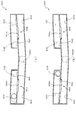
次に、図21及び図23を参照して、センターフレーム310から中間部材330への遊技球の送球を説明する。図21(a)は、センターフレーム310及び中間部材330の正面図であり、図21(b)は、センターフレーム310及び中間部材330の側面図であり、図21(c)は、図21(a)のXXIc−XXIc線におけるセンターフレーム310及び中間部材330の部分拡大断面図である。図22(a)から図22(c)は、センターフレーム310及び中間部材330の正面図である。図23(a)から図23(c)は、センターフレーム310及び中間部材330の部分拡大断面図である。   Next, with reference to FIG. 21 and FIG. 23, a description will be given of the delivery of game balls from the center frame 310 to the intermediate member 330. FIG. 21A is a front view of the center frame 310 and the intermediate member 330, FIG. 21B is a side view of the center frame 310 and the intermediate member 330, and FIG. 21C is FIG. It is a partial expanded sectional view of the center frame 310 and the intermediate member 330 in the XXIc-XXIc line | wire of a). 22A to 22C are front views of the center frame 310 and the intermediate member 330. FIG. FIG. 23A to FIG. 23C are partial enlarged cross-sectional views of the center frame 310 and the intermediate member 330.

なお、図21から図23では、センターフレーム310及び中間部材330が組み合わされた状態が図示される。また、図22及び図23では、第3状態(羽部312を軸支孔312aを中心に回転させた状態)におけるセンターフレーム310が図示され、図23(a)から図23(c)では、図21(c)の断面図と対応する断面が図示される。さらに、図22及び図23では、球の送球される遷移状態が図示される。   21 to 23 show a state in which the center frame 310 and the intermediate member 330 are combined. 22 and 23, the center frame 310 in the third state (the state in which the wing 312 is rotated around the shaft support hole 312a) is illustrated, and in FIGS. 23 (a) to 23 (c), A cross section corresponding to the cross sectional view of FIG. Furthermore, in FIG.22 and FIG.23, the transition state by which a ball | bowl is sent is illustrated.

図21(a)から図21(c)に示すように、センターフレーム310及び中間部材330が組み合わされた状態では、中間部材330の受部331aの突出先端がセンターフレーム310の上部正面カバー313の正面と重力方向における位置が略一致する。即ち、受部331aは、第1センサ311bと重力方向に対向する位置まで突設される。よって、上述したように、第1センサ311bの内部を通過して流下する遊技球を、受部331aに落下させることができる。   As shown in FIGS. 21A to 21C, in the state where the center frame 310 and the intermediate member 330 are combined, the protruding tip of the receiving portion 331 a of the intermediate member 330 is formed on the upper front cover 313 of the center frame 310. The front and the position in the direction of gravity are almost the same. That is, the receiving part 331a is provided to project to a position facing the first sensor 311b in the direction of gravity. Therefore, as described above, the game ball flowing through the first sensor 311b can be dropped onto the receiving portion 331a.

図22(a)及び図23(a)に示すように、第3状態における羽部312では、センターフレームの重力方向上側から流下する遊技球が、羽部312と当接して、2の羽部312の対向間に送球される。これにより、図22(b)及び図23(b)に示すように、球が、枠体311の凹部311aと上部正面カバー313との対向間に送球される。   As shown in FIG. 22A and FIG. 23A, in the wing part 312 in the third state, the game ball flowing down from the upper side in the gravity direction of the center frame comes into contact with the wing part 312 and the two wing parts A ball is sent between 312 faces. Thereby, as shown in FIG. 22B and FIG. 23B, the sphere is sent between the concave portion 311 a of the frame body 311 and the upper front cover 313 facing each other.

図22(b)及び図23(b)に示すように、上部正面カバー313と枠体311の凹部311aとの対向間に送球される遊技球は、凹部311aの重力方向下側縁部に配設した第1センサ311bの内側案内部331b1の内部を通過して図22(c)及び図23(c)に示す受部331aの内側に送球される。   As shown in FIGS. 22 (b) and 23 (b), a game ball sent between the upper front cover 313 and the recess 311a of the frame 311 is arranged on the lower edge of the recess 311a in the direction of gravity. The ball passes through the inside of the inner guide portion 331b1 of the first sensor 311b and is sent to the inside of the receiving portion 331a shown in FIGS. 22 (c) and 23 (c).

図22(c)及び図23(c)に示すように、第1センサ311bの内側案内部331b1の重力方向下側には、受部331aの湾曲部分(正面視U字状の湾曲部分)が位置される。これにより、受部331aに落下した遊技球が、反発して跳ね返ることを抑制できる。その結果、受部331aの内側を転動する遊技球の転動速度が遅くなることを抑制できる。   As shown in FIGS. 22 (c) and 23 (c), a curved portion (a U-shaped curved portion in front view) of the receiving portion 331a is located on the lower side in the gravity direction of the inner guide portion 331b1 of the first sensor 311b. Be positioned. Thereby, it can suppress that the game ball which fell to the receiving part 331a repels and bounces. As a result, it can suppress that the rolling speed of the game ball rolling inside the receiving part 331a becomes slow.

次に、図24を参照して、受部331aの上面を転動する遊技球について説明する。図24(a)から図24(c)は、センターフレーム310及び中間部材330の断面図である。なお、図24(a)から図24(c)は、受部331aの上面を転動する遊技球の遷移状態が図示される。また、図24(a)から図24(c)は、図21(c)の断面と対応する。   Next, with reference to FIG. 24, the game ball rolling on the upper surface of the receiving portion 331a will be described. 24A to 24C are sectional views of the center frame 310 and the intermediate member 330. FIG. FIGS. 24A to 24C illustrate the transition state of the game ball rolling on the upper surface of the receiving portion 331a. Further, FIGS. 24A to 24C correspond to the cross section of FIG.

図24(a)から図24(c)に示すように、受部331aの上面に送球される遊技球は、基部側(背面側)に向かう下降傾斜により、受部331aの上面を転動して受部331aの基部側に転動する。この際、上述したように、第1センサ311bの内側案内部331b1の重力方向下側には、受部331aの湾曲部分が位置するので、内側案内部331b1から流下する遊技球を受部331aの湾曲部分に衝突させることができる。これにより、重力方向に流下する遊技球に、左右方向へ変位を付与することができる。従って、受部331aの上面を流下する遊技球の転動を受部331aの基部に向かう転動だけでなく、左右方向へ転動させることができ、遊技者に遊技球の転動状態を長く見せて遊技者の興趣を向上することができる。   As shown in FIG. 24 (a) to FIG. 24 (c), the game ball sent to the upper surface of the receiving portion 331a rolls on the upper surface of the receiving portion 331a by a downward inclination toward the base side (back side). And roll to the base side of the receiving portion 331a. At this time, as described above, since the curved portion of the receiving portion 331a is located below the inner guide portion 331b1 of the first sensor 311b in the gravity direction, the game ball flowing down from the inner guide portion 331b1 is received by the receiving portion 331a. It can collide with a curved part. Thereby, it is possible to give a displacement in the left-right direction to the game ball flowing down in the direction of gravity. Therefore, the rolling of the game ball flowing down the upper surface of the receiving portion 331a can be rolled not only to the base of the receiving portion 331a but also in the left-right direction, and the player can make the rolling state of the gaming ball longer. Show and improve the interest of the player.

また、湾曲部分は平坦面よりも剛性が高くなるので、受部331aの上面への遊技球の流下位置を湾曲部分とすることで、受部331aの上面へ遊技球が落下した際に受部331aがその衝撃により破損することを抑制できる。   In addition, since the curved portion has higher rigidity than the flat surface, the receiving portion when the game ball falls to the upper surface of the receiving portion 331a can be obtained by setting the flowing position of the gaming ball to the upper surface of the receiving portion 331a as the curved portion. It can suppress that 331a is damaged by the impact.

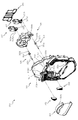
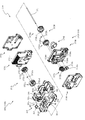
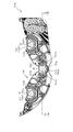
次に、図25から図27を参照して、後方部材350について説明する。図25(a)は、後方部材350の正面図であり、図25(b)は、後方部材350の背面図であり、図25(c)は、図25(a)のXXVc−XXVc線における後方部材350の断面図である。図26は、後方部材350の分解正面斜視図であり、図27は、後方部材350の分解背面斜視図である。   Next, the rear member 350 will be described with reference to FIGS. 25 to 27. 25 (a) is a front view of the rear member 350, FIG. 25 (b) is a rear view of the rear member 350, and FIG. 25 (c) is taken along line XXVc-XXVc in FIG. 25 (a). 4 is a cross-sectional view of a rear member 350. FIG. FIG. 26 is an exploded front perspective view of the rear member 350, and FIG. 27 is an exploded rear perspective view of the rear member 350.

図25から図27に示すように、後方部材350は、正面視略台形の板状体から形成される背面本体部351と、その背面本体部351の中央部に前後方向に開口する開口351bの内側に変位可能に配設される可変板352と、可変板352を間に挟む様態で背面本体部351に取着されて可変板352の変位に伴ってその内部に遊技球が送球される入賞部材353と、入賞部材353に取着され入賞部材353の内部の遊技球の送球経路を形成する装飾部材354と、装飾部材354に取着されると共に装飾部材354を介して遊技者側に光を照射する発光部材355と、可変板352に駆動力を付与するソレノイド356と、装飾部材354との間にソレノイド356を介した状態で取着されソレノイド356を脱落不能に保持するカバー部材357とを主に備えて形成される。   As shown in FIGS. 25 to 27, the rear member 350 includes a rear body portion 351 formed from a substantially trapezoidal plate-like body when viewed from the front, and an opening 351 b that opens in the front-rear direction at the center of the rear body portion 351. A variable plate 352 that is displaceably disposed on the inside, and a prize that is attached to the back body 351 with the variable plate 352 interposed therebetween, and a game ball is sent to the inside as the variable plate 352 is displaced. A member 353, a decoration member 354 attached to the winning member 353 and forming a game ball sending path inside the winning member 353, and attached to the decorative member 354 and lighted to the player side through the decorative member 354 The light emitting member 355 for irradiating the light, the solenoid 356 for applying a driving force to the variable plate 352, and the decorative member 354 are attached via the solenoid 356 so that the solenoid 356 is held so as not to fall off. And over member 357 is formed mainly includes.

背面本体部351は、正面側に断面U字状に突出する立設部351aと、立設部351aの内側に形成されると共に正面から背面に亘って開口する開口351bと、開口351bの左右方向両外側に位置すると共に後述する可変板352の軸部352aを保持する軸受部352fと、開口351bの重力方向下側に正面から背面に亘って開口し開口351bから背面側に送球される遊技球を前方に案内する連結孔351cと、背面本体部351の重力方向下側端部に前方から背面に向かって凹設される第1凹部351d及び第2凹部351eとを主に備えて形成される。   The back body 351 includes a standing portion 351a that protrudes in a U-shaped cross section on the front side, an opening 351b that is formed inside the standing portion 351a and that extends from the front to the back, and the left-right direction of the opening 351b. A bearing portion 352f which is located on both outer sides and holds a shaft portion 352a of a variable plate 352 described later, and a game ball which is opened from the front to the back on the lower side in the gravity direction of the opening 351b and is sent from the opening 351b to the back side Are mainly provided with a first recess 351d and a second recess 351e that are recessed from the front toward the back at the lower end of the back body 351 in the direction of gravity. .

背面本体部351は、中間部材330(本体部331)の受部331aを転動する(中間部材330を送球される)遊技球を、重力方向下側へ流下させる部材であり、中間部材330の背面側と遊技球の直径よりも大きい間隔を空けて中間部材330に取着される。これにより、中間部材330と背面本体部351との対向間に遊技球を流下させることができる。   The back main body portion 351 is a member that causes the game ball that rolls (receives the intermediate member 330) to roll down the receiving portion 331 a of the intermediate member 330 (main body portion 331) to flow downward in the gravitational direction. It is attached to the intermediate member 330 with a space larger than the back side and the diameter of the game ball. Thereby, the game ball can be caused to flow down between the intermediate member 330 and the back body portion 351.

また、背面本体部351は、正面視における外形が中間部材330の外形と略同一もしくは小さく形成される。これにより、組み上げた状態の可動入球役物装置300のセンターフレーム310よりも正面視外側に部材が突出することを抑制して、可動入球役物装置300をベース板60の開口60aに取着する際に前方から可動入球役物装置300を挿入するのみで配置することができ、可動入球役物装置300のベース板60への取り付けを簡易に行うことができる。   Further, the rear body 351 is formed so that the outer shape in front view is substantially the same as or smaller than the outer shape of the intermediate member 330. As a result, it is possible to prevent the member from protruding outward from the center frame 310 of the assembled movable entrance ball apparatus 300 in the assembled state, and to attach the movable entrance ball apparatus 300 to the opening 60a of the base plate 60. When wearing, it can be arranged simply by inserting the movable incoming ball accessory device 300 from the front, and the movable incoming ball accessory device 300 can be easily attached to the base plate 60.

立設部351aは、正面視において下側が開放するU字状に形成される。立設部351aは、その対向間の幅寸法が小さい第1立設部351a1と、その第1立設部351a1よりも対向間の距離寸法が大きい第2立設部351a2と、を備える。   The standing portion 351a is formed in a U shape whose lower side is opened in a front view. The standing portion 351a includes a first standing portion 351a1 having a small width dimension between the facing portions, and a second standing portion 351a2 having a larger distance dimension between the facing portions than the first standing portion 351a1.

第1立設部351a1は、左右両側の対向間の距離寸法が中間部材330の受部331aの左右両側の対向間の距離寸法と略同一に設定され、左右両側の端部が受部331aの左右両側の端部と前後方向に対向する位置に配設される。また、第1立設部351a1の上方端部の重力方向の高さ位置は、受部331aの上端一致と略同一に設定される。これにより、中間部材330の受部331aの上面を転動して送球される遊技球を、中間部材330と背面本体部351との対向間に流下させることができると共に、立設部351aの内側に流下させることができる。   In the first standing portion 351a1, the distance between the left and right sides of the receiving portion 331a of the intermediate member 330 is set to be substantially the same as the distance between the left and right sides of the receiving portion 331a. It is arrange | positioned in the position which opposes the edge part on either side on either side in the front-back direction. Further, the height position in the gravity direction of the upper end portion of the first standing portion 351a1 is set to be substantially the same as the upper end coincidence of the receiving portion 331a. Thereby, the game ball that is sent by rolling on the upper surface of the receiving portion 331a of the intermediate member 330 can be caused to flow down between the intermediate member 330 and the back main body portion 351, and the inside of the standing portion 351a. Can flow down.

第2立設部351a2は、第1立設部352a1の重力方向下側の端部と連結して形成される。第2立設部351a2の対向間の距離寸法は、開口351bの長手方向寸法と略同一に設定され、開口351bの内側に配設される可変板352が可変した際に、可変板352の長手方向外側を遊技球が流下することを抑制できる。これにより、可変板352を変位させた際に、背面本体部と351と中間部材330との対向間を流下する遊技球を開口351bに確実に送球させることができる。   The second standing portion 351a2 is formed by being connected to the lower end portion of the first standing portion 352a1 in the gravity direction. The distance dimension between the facing portions of the second standing portion 351a2 is set to be approximately the same as the longitudinal dimension of the opening 351b, and when the variable plate 352 disposed inside the opening 351b is varied, the longitudinal dimension of the variable plate 352 is changed. It is possible to suppress the game ball from flowing down on the outside in the direction. Thereby, when the variable plate 352 is displaced, it is possible to reliably cause the game ball flowing down between the back body portion, the 351 and the intermediate member 330 to face the opening 351b.

開口351bは、中間部材330及び背面本体部351の対向間を流下する遊技球を背面本体部351の背面側に送球可能にするための開口であり、正面視横長矩形に形成されると共にその短手方向の幅寸法が遊技球の直径よりも大きく設定される。また、上述したように、開口351bは、第2立設部351a2の左右の対向間に形成される。   The opening 351b is an opening for allowing a game ball flowing down between the intermediate member 330 and the back main body portion 351 to face the back side of the back main body portion 351, and is formed in a horizontally long rectangle when viewed from the front. The width dimension in the hand direction is set larger than the diameter of the game ball. Further, as described above, the opening 351b is formed between the left and right opposing portions of the second standing portion 351a2.

連結孔351cは、開口351bの内部を通過して背面本体部の背面側に送球された遊技球を後述する入賞部材353を介して正面側に送球する孔であり、開口351bの重力方向下方に位置すると共に、球の直径よりも大きい矩形状に開口して形成される。また、連結孔351cは、左右方向に並んで2つ並設される。   The connection hole 351c is a hole through which the game ball passed through the inside of the opening 351b and sent to the back side of the back main body part is sent to the front side through a prize-winning member 353 described later, and below the opening 351b in the gravitational direction. It is located and formed in a rectangular shape larger than the diameter of the sphere. Two connecting holes 351c are arranged side by side in the left-right direction.

第1凹部351dは、連結孔351cから背面本体部351の正面側に送球された遊技球が、上述した中間部材330の内側案内部の上面に案内されて流下する経路であり、背面本体部351の重力方向下側端部に位置すると共に、背面側に向かって凹設される。   The first recess 351d is a path through which the game ball sent from the connection hole 351c to the front side of the rear body 351 is guided and flows down to the upper surface of the inner guide part of the intermediate member 330 described above. And is recessed toward the back side.

また、第1凹部351dは、中間部材330に背面本体部351(後方部材350)が配置された際に、正面視において中間部材330の内側案内部331b1と外側案内部331b2との対向間に位置して形成される。よって、内側案内部331b1と外側案内部331b2との対向間を流下する遊技球の流下方向を背面側に変位させることができる。これにより、中間部材330と背面本体部351との対向間を送球される遊技球が、後述する可変ユニット360に流下される際に、重力方向への流下速度を遅くすることができる。従って、可変ユニット360に遊技球が送球される際に、可変ユニット360と衝突して遊技球が跳ねることを抑制でき、後方部材350から可変ユニット360への送球を安定させることができる。   Further, the first concave portion 351d is positioned between the inner guide portion 331b1 and the outer guide portion 331b2 of the intermediate member 330 facing each other when the back main body 351 (the rear member 350) is disposed on the intermediate member 330. Formed. Therefore, it is possible to displace the flow direction of the game ball flowing down between the inner guide portion 331b1 and the outer guide portion 331b2 to the back side. Thereby, when the game ball sent between the opposed members of the intermediate member 330 and the back main body portion 351 is caused to flow down to the variable unit 360 described later, the flow-down speed in the direction of gravity can be reduced. Therefore, when a game ball is sent to the variable unit 360, it is possible to suppress the game ball from bouncing by colliding with the variable unit 360, and the ball from the rear member 350 to the variable unit 360 can be stabilized.

第2凹部351eは、中間部材330及び後方部材350の対向間を流下する遊技球が、中間部材330の外側案内部331b2の上面に案内されて流下する経路であり、第1凹部351dの左右方向外側に位置すると共に、背面側に向かって凹設される。   The second recess 351e is a path through which the game ball flowing down between the facing of the intermediate member 330 and the rear member 350 is guided by the upper surface of the outer guide portion 331b2 of the intermediate member 330 and flows in the left-right direction of the first recess 351d. It is located outside and is recessed toward the back side.

また、第2凹部351eは、中間部材330に背面本体部351(後方部材350)が配置された際に、正面視において中間部材330の外側案内部331b2と立設壁331cとの対向間に位置して形成される。よって、外側案内部331b2と立設壁331cとの対向間を流下する遊技球の流下方向を背面側に変位させることができる。これにより、中間部材330と背面本体部351との対向間を送球される遊技球が、後述する可変ユニット360に流下される際に、重力方向への流下速度を遅くすることができる。従って、可変ユニット360に遊技球が送球される際に、可変ユニット360と衝突して遊技球が跳ねることを抑制でき、後方部材359から可変ユニット360への送球を安定させることができる。   The second recess 351e is located between the outer guide portion 331b2 of the intermediate member 330 and the standing wall 331c when viewed from the front when the back body 351 (rear member 350) is disposed on the intermediate member 330. Formed. Therefore, it is possible to displace the flow direction of the game ball flowing down between the opposing sides of the outer guide portion 331b2 and the standing wall 331c to the back side. Thereby, when the game ball sent between the opposed members of the intermediate member 330 and the back main body portion 351 is caused to flow down to the variable unit 360 described later, the flow-down speed in the direction of gravity can be reduced. Therefore, when a game ball is sent to the variable unit 360, it is possible to suppress the game ball from bouncing by colliding with the variable unit 360, and the ball from the rear member 359 to the variable unit 360 can be stabilized.

可変板352は、上述したように、中間部材330と背面本体部351(後方部材350)との対向間を流下する遊技球を背面本体部351の開口351bの内部に送球するための案内部材であり、背面本体部351の開口351bの内側に回転可能な状態で配設される。   As described above, the variable plate 352 is a guide member for sending the game ball flowing down between the intermediate member 330 and the back main body portion 351 (rear member 350) to the inside of the opening 351b of the back main body portion 351. Yes, and arranged in a rotatable state inside the opening 351b of the back body 351.

可変板352は、透明な可撓性材料から形成される。また、可変板352は、背面本体部351の開口351bの内部に配設されると共に正面視横長矩形の板状体に形成される板部352dと、板部352dの長手方向両端から突出して回転可能に軸支される軸部352aと、その軸部352aから径方向外側に突出して可変板352が変位する際に背面本体部351と係合して可変板352の変位量を規制する第1突起352bと、その第1突起352bと径方向に異なる方向に突出して、後述する駆動手段のソレノイド356の駆動力を伝達する第2突起352cとを主に備えて形成される。   The variable plate 352 is formed from a transparent flexible material. In addition, the variable plate 352 is disposed inside the opening 351b of the back body 351 and is rotated by protruding from both ends in the longitudinal direction of the plate portion 352d and a plate portion 352d formed in a horizontally long plate-like body in front view. A shaft portion 352a that is pivotally supported, and a first member that engages with the back main body portion 351 and regulates the amount of displacement of the variable plate 352 when the variable plate 352 is displaced from the shaft portion 352a to the outside in the radial direction. The protrusion 352b is formed mainly including a first protrusion 352b and a second protrusion 352c that protrudes in a radial direction different from that of the first protrusion 352b and transmits a driving force of a solenoid 356 of a driving unit described later.

板部352dは、回転変位して中間部材330と背面本体部351との対向間を流下する遊技球を開口351bに案内する板状体であり、正面視における外形が開口351bよりも小さい横長矩形に形成される。   The plate portion 352d is a plate-like body that guides a game ball that is rotationally displaced and flows down between the facing portion of the intermediate member 330 and the back body portion 351 to the opening 351b, and has a horizontally long rectangle whose outer shape in front view is smaller than the opening 351b. Formed.

また、板部352dは、変位前の状態において中間部材330と対向する正面部352d2と、回転軸(軸部352a)と反対側の端部から中間部材330側に膨出する膨出部352d1とを備える。なお、膨出部352d1及び正面部352d2の詳しい説明は後述する。   The plate portion 352d includes a front portion 352d2 that faces the intermediate member 330 in a state before displacement, and a bulging portion 352d1 that bulges toward the intermediate member 330 from the end opposite to the rotation shaft (shaft portion 352a). Is provided. A detailed description of the bulging portion 352d1 and the front portion 352d2 will be described later.

軸部352aは、板部352dを回転変位可能に軸支される軸部であり、板部352dの長手方向両端の重力方向下側の一端から突出形成される。軸部352aは、背面本体部351の軸受部351fの内側に配置され、背面側から後述する入賞部材353が配設されることで、背面本体部351と入賞部材353との間に回転可能に保持される。これにより、可変板352は、背面本体部351に対して回転変位可能とされる。   The shaft portion 352a is a shaft portion that is rotatably supported by the plate portion 352d, and is formed to protrude from one end on the lower side in the gravity direction at both ends in the longitudinal direction of the plate portion 352d. The shaft portion 352a is disposed inside the bearing portion 351f of the back body portion 351, and a winning member 353, which will be described later, is disposed from the back side, so that it can rotate between the back body portion 351 and the winning member 353. Retained. Thereby, the variable plate 352 can be rotationally displaced with respect to the back body 351.

第1突起352bは、可変板352は回転変位した際に、背面本体部351と当接して可変板352の回転時の変位量を規制する突起であり、左右両端の軸部352aから径方向に突出して形成される。また、両端の軸部352aの第1突起352bの突出方向は、軸部352aの軸方向視において略同一に設定される。   The first protrusion 352b is a protrusion that abuts against the back body 351 when the variable plate 352 is rotationally displaced, and regulates the amount of displacement of the variable plate 352 during rotation. The first protrusion 352b radially extends from the shaft portions 352a at both left and right ends. Protrusively formed. In addition, the protruding directions of the first protrusions 352b of the shaft portions 352a at both ends are set to be substantially the same when the shaft portion 352a is viewed in the axial direction.

さらに、一方の第1突起352b(本実施形態では、正面視右側の第1突起352b)が、後述するソレノイド356の伝達部356aと係合される。これにより、ソレノイド356の駆動力を可変板352に伝達できる。よって、ソレノイド356の駆動力により可変板352を軸部352aの軸周りに回転させることができる。   Furthermore, one first protrusion 352b (in this embodiment, the first protrusion 352b on the right side in front view) is engaged with a transmission portion 356a of a solenoid 356 described later. Thereby, the driving force of the solenoid 356 can be transmitted to the variable plate 352. Therefore, the variable plate 352 can be rotated around the axis of the shaft portion 352a by the driving force of the solenoid 356.

また、一方の第1突起352bの軸部352aには、第2突起352cが軸部352aから径方向に突出して形成される。軸部352aの軸方向視において、第1突起352bと第2突起352cとは、軸周りに所定の隙間を有して形成され、その隙間にソレノイド356の伝達部356aの先端部が挿入される。これにより、ソレノイド356から駆動力が付与されて伝達部356aが変位することで、可変板352を軸部252aの軸周りに回転させることができる。なお、可変板352の動作の詳しい説明は後述する。   Further, a second protrusion 352c is formed on the shaft portion 352a of the first protrusion 352b so as to protrude from the shaft portion 352a in the radial direction. When the shaft portion 352a is viewed in the axial direction, the first protrusion 352b and the second protrusion 352c are formed with a predetermined clearance around the shaft, and the tip of the transmission portion 356a of the solenoid 356 is inserted into the clearance. . As a result, the driving force is applied from the solenoid 356 and the transmission portion 356a is displaced, so that the variable plate 352 can be rotated around the axis of the shaft portion 252a. A detailed description of the operation of the variable plate 352 will be described later.

入賞部材353は、可変板352が変位して背面本体部351の開口351bの内部に送球された遊技球が流下する経路を形成する部材であり、背面本体部351の開口351bに連結される連結孔353aと、その連結孔353aの内縁に下方に向かって開口する第2検出孔353bと、第2検出孔353bと一端が連結されると共に他端が正面側に開口する前側開口353cと、背面側に形成される第1乱反射部353dと、ソレノイド356の伝達部356aが挿通される貫通孔353eと、第1乱反射部353dの縁部から立設する立設壁353fとを主に備えて形成される。   The winning member 353 is a member that forms a path through which the game ball sent to the inside of the opening 351b of the back body 351 is displaced by the displacement of the variable plate 352, and is connected to the opening 351b of the back body 351. A hole 353a, a second detection hole 353b opening downward to the inner edge of the connection hole 353a, a front detection opening 353c having one end connected to the second detection hole 353b and the other end opening to the front side, and a rear surface The first irregular reflection part 353d formed on the side, the through hole 353e through which the transmission part 356a of the solenoid 356 is inserted, and the standing wall 353f standing from the edge of the first irregular reflection part 353d are mainly formed. Is done.

連結孔353aは、背面本体部351の開口351bの正面視における外形と略同一の外形に貫通形成されると共に、開口351bと対向する位置に形成される。これにより、開口351bの内部に送球される遊技球を連結孔353aの内部に送球させることができる。   The connecting hole 353a is formed to penetrate the outer shape substantially the same as the outer shape of the opening 351b of the back main body 351 when viewed from the front, and is formed at a position facing the opening 351b. Thereby, a game ball sent into the opening 351b can be sent into the connection hole 353a.

第2検出孔353bは、球の通過を検知するセンサで形成される孔であり、球の直径よりも大きい内径で形成される。第2検出孔353bは、連結孔353aの重力方向下側の内縁部に形成されると共に、重力方向に開口して形成される。これにより、連結孔353aの内部に送球される遊技球を第2検出孔353bを通過させて送球できると共に、第2検出孔353bを通過する際に、センサによりその球数を検知することで、開口351bを通過する球数を計測できる。   The second detection hole 353b is a hole formed by a sensor that detects passage of a sphere, and is formed with an inner diameter larger than the diameter of the sphere. The second detection hole 353b is formed at the inner edge of the connection hole 353a on the lower side in the gravitational direction and is formed to open in the gravitational direction. Thereby, the game ball sent to the inside of the connection hole 353a can be sent through the second detection hole 353b, and when passing through the second detection hole 353b, the number of balls is detected by the sensor, The number of spheres passing through the opening 351b can be measured.

前側開口353cは、第2検出孔353bに送球される遊技球を、背面本体部351の連結孔351cの内部に遊技球を送球するための孔であり、開口の一端が第2検出孔353bに連結され、他端が背面本体部351の連結孔351cに背面側から連結される。よって、背面本体部351の開口351bの内部に送球される遊技球を、第2検出孔353bを介して前側開口353cの内側を通過させて、背面本体部351の連結孔351cから排出できる。   The front opening 353c is a hole for sending a game ball sent to the second detection hole 353b into the connection hole 351c of the back body 351, and one end of the opening is connected to the second detection hole 353b. The other end is connected to the connection hole 351c of the back body 351 from the back side. Therefore, the game ball sent to the inside of the opening 351b of the back body part 351 can be discharged from the connection hole 351c of the back body part 351 through the inside of the front opening 353c through the second detection hole 353b.

第1乱反射部353dは、後述する発光部材355のLED355aから照射される光を乱反射させて前方に出射させる乱反射面であり、透明な可撓性材料から形成されると共に複数の凹凸面で形成される。発光部材355のLED355aから照射される光を複数の凹凸面に入射させることにより、第1乱反射部353dの正面側から遊技者側に出射される光の進行方向が分散され、第1乱反射部353dを効率よく光らせることができる。   The first irregular reflection portion 353d is an irregular reflection surface that irregularly reflects light emitted from the LED 355a of the light emitting member 355 described later and emits the light forward, and is formed of a transparent flexible material and a plurality of uneven surfaces. The By making the light emitted from the LED 355a of the light emitting member 355 incident on the plurality of uneven surfaces, the traveling direction of the light emitted from the front side of the first irregular reflection part 353d to the player side is dispersed, and the first irregular reflection part 353d. Can be efficiently illuminated.

貫通孔353eは、ソレノイド356の伝達部356aを背面側から正面側に挿通させる開口であり、正面視において伝達部356aの外形よりも大きい縦長矩形に形成されると共に、ソレノイド356の伝達部356aと対向する位置に貫通形成される。   The through-hole 353e is an opening through which the transmission part 356a of the solenoid 356 is inserted from the back side to the front side. The through hole 353e is formed in a vertically long rectangle larger than the outer shape of the transmission part 356a in the front view, and the transmission part 356a of the solenoid 356 It penetrates and is formed in the position which opposes.

立設壁353fは、発光部材355のLED355aから照射される光が外側に逃げることを抑制する壁であり、その立設高さが装飾部材354に当接する位置に設定される。よって、LED355aから第1乱反射部353d側に照射される光が、立設壁353fから外側に逃げることを抑制することができる。   The standing wall 353f is a wall that prevents light emitted from the LED 355a of the light emitting member 355 from escaping to the outside, and the standing height is set at a position where the standing member abuts the decorative member 354. Therefore, it can suppress that the light irradiated to the 1st irregular reflection part 353d side from LED355a escapes outside from the standing wall 353f.

装飾部材354は、正面視略矩形の板状体に形成されると共に、正面視における外形が入賞部材353の外形と略同一とされる。装飾部材354は、後述する発光部材355と対向する面に形成される第2乱反射部354bと、入賞部材353の第1乱反射部353dと対向する位置に貫通形成される開口354aと、ソレノイド356の伝達部356aと対向する位置に貫通形成される貫通孔354cとを主に備えて形成される。   The decoration member 354 is formed in a substantially rectangular plate-like body in front view, and the outer shape in front view is substantially the same as the outer shape of the winning member 353. The decoration member 354 includes a second irregular reflection portion 354b formed on a surface facing the light emitting member 355, which will be described later, an opening 354a formed penetrating at a position facing the first irregular reflection portion 353d of the winning member 353, and a solenoid 356. It is mainly provided with a through-hole 354c that is formed so as to penetrate at a position facing the transmission portion 356a.

開口354aは、発光部材355のLED355aから発光される光を入賞部材353の第1乱反射部353dに直接照射させるための開口であり、正面視における第1乱反射部353dの外形と略同一の矩形に開口されると共に、第1乱反射部353dと対向する位置に形成される。   The opening 354a is an opening for directly irradiating the light emitted from the LED 355a of the light emitting member 355 to the first irregular reflection portion 353d of the winning member 353, and has a substantially same rectangle as the outer shape of the first irregular reflection portion 353d in front view. The opening is formed at a position facing the first irregular reflection portion 353d.

第2乱反射部354bは、背面側に配設される発光部材355のLED355aから照射される光を乱反射させて前方に出射させる乱反射面であり、透明な可撓性材料から形成されると共に複数の凹凸が形成される。これにより、発光部材355のLED355aから出射される光を複数の凹凸に入射させることにより、第2乱反射部354bの正面側から出射される光の進行方向が分散され、第2乱反射部354bを効率よく発光させることができる。   The second irregular reflection portion 354b is an irregular reflection surface that irregularly reflects light emitted from the LED 355a of the light emitting member 355 disposed on the back side and emits it forward, and is formed of a transparent flexible material and includes a plurality of Unevenness is formed. Thereby, by making the light emitted from the LED 355a of the light emitting member 355 incident on the plurality of irregularities, the traveling direction of the light emitted from the front side of the second irregular reflection part 354b is dispersed, and the second irregular reflection part 354b is made efficient. Can emit light well.

貫通孔354cは、ソレノイド356の伝達部356aを背面側から正面側に挿通させる開口であり、正面視において伝達部356aの外形よりも大きい縦長矩形に形成されると共に、ソレノイド356の伝達部356aと対向する位置に貫通形成される。   The through-hole 354c is an opening through which the transmission part 356a of the solenoid 356 is inserted from the back side to the front side, and is formed in a vertically long rectangle larger than the outer shape of the transmission part 356a in front view, and the transmission part 356a of the solenoid 356 It penetrates and is formed in the position which opposes.

発光部材355は、正面側(装飾部材354と対向する側)に光を照射する発光手段のLED355aが搭載されており、装飾部材354の背面側に取着される。これにより、第1乱反射部353d及び第2乱反射部354bに光を照射することができる。   The light emitting member 355 is mounted with an LED 355a of light emitting means for irradiating light on the front side (side facing the decorative member 354), and is attached to the back side of the decorative member 354. Thereby, light can be irradiated to the 1st irregular reflection part 353d and the 2nd irregular reflection part 354b.

ソレノイド356は、可変板352に駆動力を伝達する伝達部356aを備える。ソレノイド356は、上述したように、可変板352に回転の駆動力を付与する駆動手段であり、電力が付与されることで、伝達部356aが重力方向に変位される。   The solenoid 356 includes a transmission unit 356 a that transmits a driving force to the variable plate 352. As described above, the solenoid 356 is a driving unit that applies a rotational driving force to the variable plate 352, and the transmission unit 356a is displaced in the direction of gravity when electric power is applied.

伝達部356aは、入賞部材353の貫通孔353e及び装飾部材354の貫通孔354cの内部を挿通されて、可変板352の第1突起352b及び第2突起352cとの間に配置される。よって、伝達部356aが変位すると、可変板352が軸部352aの軸周りに回転される。   The transmission part 356a is inserted between the through hole 353e of the winning member 353 and the through hole 354c of the decoration member 354, and is disposed between the first protrusion 352b and the second protrusion 352c of the variable plate 352. Therefore, when the transmission part 356a is displaced, the variable plate 352 is rotated around the axis of the shaft part 352a.

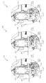
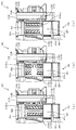
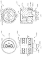
次に、図28及び図29を参照して、可変板352の変位様態を詳しく説明する。図28(a)から図28(c)は、図25のXXVIII−XXVIII線における後方部材350の断面図である。図29(a)から図29(c)は、後方部材350の断面図である。なお、図28(a)及び図29(a)は第1回転状態の可変板352が、図28(b)及び図29(b)は、第2回転状態の可変板352が、図28(c)及び図29(c)は、第3回転状態の可変板352が、それぞれ図示される。また、図29(a)から図29(c)は、図25(c)の断面と対応する。   Next, the displacement state of the variable plate 352 will be described in detail with reference to FIGS. FIG. 28A to FIG. 28C are cross-sectional views of the rear member 350 taken along the line XXVIII-XXVIII in FIG. FIG. 29A to FIG. 29C are cross-sectional views of the rear member 350. 28A and 29A show the variable plate 352 in the first rotation state, and FIGS. 28B and 29B show the variable plate 352 in the second rotation state in FIG. FIG. 29C shows the variable plate 352 in the third rotation state. Further, FIGS. 29A to 29C correspond to the cross section of FIG.

図28(a)に示すように、ソレノイド356の伝達部356aが重力方向下方に位置する第1回転状態では、伝達部356aが可変板352の第2突起352cの一側と当接すると共に、第2突起352cの他側と背面本体部351の背面側とが当接した状態とされる。即ち、第2突起352cが、伝達部356aと背面本体部351との間に挟持された状態とされる。これにより、可変板352が軸部352aの軸周りにぐらついて回転変位することを抑制できる。   As shown in FIG. 28A, in the first rotation state where the transmission portion 356a of the solenoid 356 is positioned below the gravity direction, the transmission portion 356a abuts on one side of the second protrusion 352c of the variable plate 352, and the first The other side of the two protrusions 352c is in contact with the back side of the back body 351. That is, the second protrusion 352c is sandwiched between the transmission portion 356a and the back main body portion 351. As a result, it is possible to suppress the variable plate 352 from rotating and displacing around the axis of the shaft portion 352a.

図29(a)に示すように、第1回転状態における可変板352は、軸部352aに対して膨出部352d1が重力方向上側に位置されると共に、正面部352d2が背面本体部351の開口351bを覆う(塞ぐ)様態とされる。なお、この場合、開口351bの重力方向上側の端面と可変板352との最短の距離寸法L1は、球の直径よりも小さく設定される。これにより、中間部材330と背面本体部351との対向間に送球される遊技球は、開口351bの内部に送球されず、可変板352の前方を流下様態とされる。   As shown in FIG. 29A, in the variable plate 352 in the first rotation state, the bulging portion 352d1 is positioned on the upper side in the gravity direction with respect to the shaft portion 352a, and the front portion 352d2 is the opening of the rear body portion 351. 351b is covered (closed). In this case, the shortest distance dimension L1 between the end surface of the opening 351b on the upper side in the gravity direction and the variable plate 352 is set smaller than the diameter of the sphere. As a result, the game balls sent between the intermediate member 330 and the back main body portion 351 are not sent into the opening 351b, but are brought into a flow-down state in front of the variable plate 352.

また、第1回転状態では、正面部352d2が軸部352aから離間するに従って前方に傾斜する様態とされると共に、背面本体部351の正面の平面上に膨出部352d1の先端部分が位置される。   In the first rotation state, the front portion 352d2 is inclined forward as it separates from the shaft portion 352a, and the tip portion of the bulging portion 352d1 is positioned on the front plane of the back body portion 351. .

図28(a)及び図29(a)に示す状態から、ソレノイド356に電力が付与されて、伝達部356aが重力方向上方に変位して、伝達部356aが全変位量の半分変位された図28(b)及び図29(b)に示す第2回転状態では、伝達部356aが可変板352の第1突起352bと当接して第1突起352bを軸部352aの軸周りに回転させる。これにより、可変板352が軸部352aの軸周りに回転される。   28 (a) and 29 (a), power is applied to the solenoid 356, the transmission part 356a is displaced upward in the direction of gravity, and the transmission part 356a is displaced by half of the total displacement. In the second rotation state shown in FIG. 28B and FIG. 29B, the transmission portion 356a abuts on the first projection 352b of the variable plate 352 and rotates the first projection 352b around the axis of the shaft portion 352a. Thereby, the variable plate 352 is rotated around the axis of the shaft portion 352a.

図29(b)に示すように、第2回転状態における可変板352は、膨出部352d1が、軸部352aに対して正面側に位置されると共に、正面部352d2の正面側への上方傾斜の傾斜角度が第1回転状態よりも小さくされる。なお、この場合、開口351bの重力方向上側の端面と可変板352との最短の距離寸法L2は、球の直径よりも小さく設定される。   As shown in FIG. 29B, in the variable plate 352 in the second rotation state, the bulging portion 352d1 is positioned on the front side with respect to the shaft portion 352a, and the front portion 352d2 is inclined upward to the front side. Is made smaller than that in the first rotation state. In this case, the shortest distance dimension L2 between the end surface of the opening 351b on the upper side in the gravity direction and the variable plate 352 is set smaller than the diameter of the sphere.

図28(b)及び図29(b)に示す状態から、ソレノイド356に電力が付与され続けて、伝達部356aが、重力方向上方に変位して、伝達部356aが、終端まで変位された図28(c)及び図29(c)に示す第3回転状態では、伝達部356aが可変板352の第1突起352bと当接して第1突起352bを軸部352aの軸周りにさらに回転させる。これにより、可変板352が第2回転状態よりもさらに軸部352aの軸周りに回転される。   FIG. 28B is a diagram in which power is continuously applied to the solenoid 356 from the state shown in FIG. 28B and FIG. 29B, the transmission unit 356a is displaced upward in the direction of gravity, and the transmission unit 356a is displaced to the end. In the third rotation state shown in FIG. 28C and FIG. 29C, the transmission portion 356a abuts on the first projection 352b of the variable plate 352 and further rotates the first projection 352b around the axis of the shaft portion 352a. Thereby, the variable plate 352 is further rotated around the axis of the shaft portion 352a than in the second rotation state.

また、図28(c)に示すように、第3回転状態では、伝達部356aと第1突起352bの一端が当接すると共に、中間部材330と第1突起352bの他端が当接する様態とされる。即ち、第1突起352bは、背面本体部351と伝達部356aとの間に挟まれた状態とされる。これにより、可変板352が軸部352aの軸周りにぐらついて回転変位することを抑制できる。   As shown in FIG. 28C, in the third rotation state, the transmission portion 356a and one end of the first protrusion 352b are in contact with each other, and the intermediate member 330 and the other end of the first protrusion 352b are in contact with each other. The That is, the first protrusion 352b is sandwiched between the back main body portion 351 and the transmission portion 356a. As a result, it is possible to suppress the variable plate 352 from rotating and displacing around the axis of the shaft portion 352a.

図29(c)に示すように、第3回転状態における可変板352は、軸部352aに対して膨出部352d1が正面側に位置される。この場合、開口351bの重力方向上側の端面と可変板352との最短の距離寸法L3は、球の直径よりも大きく設定される。これにより、中間部材330と背面本体部351との対向間に送球される遊技球は、開口351bの内部に送球される。   As shown in FIG. 29C, in the variable plate 352 in the third rotation state, the bulging portion 352d1 is positioned on the front side with respect to the shaft portion 352a. In this case, the shortest distance dimension L3 between the end surface of the opening 351b on the upper side in the gravity direction and the variable plate 352 is set larger than the diameter of the sphere. As a result, the game ball that is sent between the intermediate member 330 and the back body portion 351 is sent into the opening 351b.

また、第3回転状態では、正面部352d2の反対面が、軸部352aから離間するに従って上方に位置する上方傾斜とされる。よって、板部352dの上方に送球される遊技球を背面本体部351の開口351bの内部に送球することができる。   Further, in the third rotation state, the opposite surface of the front portion 352d2 is inclined upward as it is separated from the shaft portion 352a. Therefore, a game ball sent to the upper side of the plate portion 352d can be sent to the inside of the opening 351b of the back body portion 351.

よって、第1乱反射部353dと発光手段との間の距離が、第2乱反射部354bと発光手段との間の距離よりも大きくされ、可変板352と第2乱反射部354bとの対向間が遊技球の第1の流下経路とされるので、可変板352、第1乱反射部353dおよび第2乱反射部354bからなるユニットの小型化を図ることができる。即ち、遊技者に視認させる光の態様を異ならせるために形成された可変板352および第2乱反射部354bの間の空間を、遊技球の第1の流下経路とすることで、デッドスペースを有効に活用でき、流下経路のための空間を別途確保する必要がない。よって、その分、ユニットの小型化を図ることができる。   Therefore, the distance between the first irregular reflection part 353d and the light emitting means is made larger than the distance between the second irregular reflection part 354b and the light emitting means, and the distance between the variable plate 352 and the second irregular reflection part 354b is a game. Since it is the first flow path of the sphere, the unit composed of the variable plate 352, the first irregular reflection portion 353d, and the second irregular reflection portion 354b can be reduced in size. In other words, the space between the variable plate 352 and the second irregularly reflecting portion 354b formed to vary the form of light visually recognized by the player is used as the first flow path of the game ball, thereby making the dead space effective. It is not necessary to secure a separate space for the flow path. Therefore, the unit can be reduced in size accordingly.

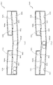
次いで、図30及び図31を参照して、中間部材330及び後方部材350の詳しい説明をする。図30(a)は、中間部材330及び後方部材350の正面図であり、図30(b)は、中間部材330及び後方部材350の側面図である。図31(a)は、図30(a)のXXXIa−XXXIa線における中間部材330及び後方部材350の断面図であり、図31(b)は、図30(b)のXXXIb−XXXIb線における中間部材330及び後方部材350の断面図である。   Next, the intermediate member 330 and the rear member 350 will be described in detail with reference to FIGS. 30 and 31. FIG. 30A is a front view of the intermediate member 330 and the rear member 350, and FIG. 30B is a side view of the intermediate member 330 and the rear member 350. FIG. 31A is a cross-sectional view of the intermediate member 330 and the rear member 350 taken along the line XXXIa-XXIa of FIG. 30A, and FIG. 31B is the middle taken along the line XXXIb-XXXIb of FIG. 4 is a cross-sectional view of a member 330 and a rear member 350. FIG.

図30及び図31に示すように、LED355aと第2乱反射部354bとの対向間の距離寸法L4は、LED355aと第1乱反射部353dとの対向間の距離寸法L5よりも小さく設定される(L4<L5)。また、第2乱反射部354bの光透過方向に、可変板352が配設される。   As shown in FIGS. 30 and 31, the distance dimension L4 between the facing of the LED 355a and the second irregular reflection part 354b is set smaller than the distance dimension L5 between the facing of the LED 355a and the first irregular reflection part 353d (L4). <L5). In addition, the variable plate 352 is disposed in the light transmission direction of the second irregular reflection portion 354b.

ここで、遊技者から視認可能な位置に変位可能に配設され変位位置に応じて遊技球の流下経路を切り替える変位部材(可変板352)を備えた遊技機が知られている。この場合、透明な可撓性材料から形成される透過部材の正面側に変位部材を配設し、透過部材の背面から光を照射することで、透過部材を透過した光と共に変位部材を遊技者に視認させ、変位部材に着目させるという技術も知られている。しかしながら、従来の上述した技術では、変位部材が光を透過しない非透過性材料から形成されるため、その変位部材の大きさの分、遊技者に視認させる光の領域(面積)が減少され、演出効果が阻害される。   Here, a gaming machine is known that includes a displacement member (variable plate 352) that is displaceably disposed at a position that can be visually recognized by a player and that switches a flow path of a game ball in accordance with the displacement position. In this case, the displacement member is arranged on the front side of the transparent member formed of a transparent flexible material, and the player is able to irradiate light from the back surface of the transparent member, so that the displacement member is combined with the light transmitted through the transparent member. There is also known a technique of making a user visually recognize and pay attention to a displacement member. However, in the conventional technology described above, since the displacement member is formed of a non-transmissive material that does not transmit light, the area (area) of light that is visually recognized by the player is reduced by the size of the displacement member, The production effect is hindered.

これを受け、変位部材(可変板352)を透明な可撓性材料から形成することで、透過部材に加え、変位部材を透過する光も遊技者に視認可能として、遊技者に視認させる光の領域(面積)を確保する技術を開発した(本出願時において未公知)。しかしながら、変位部材を透明な可撓性材料から形成した場合には、かかる変位部材の位置を遊技者が特定し難いという問題点のあることが判明した。   In response to this, by forming the displacement member (variable plate 352) from a transparent flexible material, in addition to the transmission member, the light transmitted through the displacement member can be visually recognized by the player, and the light to be visually recognized by the player can be seen. A technology for securing a region (area) has been developed (unknown at the time of this application). However, it has been found that when the displacement member is made of a transparent flexible material, it is difficult for the player to specify the position of the displacement member.

これに対し、本実施形態によれば、光を発光可能に形成される1又は複数の発光手段(LED355a)が発光面を正面側へ向けて搭載される基板部材(発光部材355)と、その基板部材の正面側に配設され光透過材料から形成される第1透過部材(第1乱反射部353d)および第2透過部材(第2乱反射部354b)とを備え、変位部材が透明な可撓性材料から形成されると共に前記第2透過部材の正面側に配設され、第2透過部材と基板部材との間の距離が、第1透過部材と基板部材との間の距離と異なる距離に設定されるので、遊技者に視認させる光の領域(面積)を確保しつつ、変位部材の位置を遊技者に特定させやすくできる。   On the other hand, according to the present embodiment, a substrate member (light emitting member 355) on which one or a plurality of light emitting means (LEDs 355a) formed to emit light is mounted with the light emitting surface facing the front side, The first transmissive member (first irregular reflection portion 353d) and the second transmissive member (second irregular reflection portion 354b) which are disposed on the front side of the substrate member and are formed of a light transmissive material, and the displacement member is transparent and flexible. The distance between the second transmission member and the substrate member is different from the distance between the first transmission member and the substrate member. Since it is set, it is possible to make it easier for the player to specify the position of the displacement member while securing a light region (area) to be visually recognized by the player.

即ち、第1透過部材(第1乱反射部353d)と第2透過部材(第2乱反射部354b)とで発光手段(LED355a)からの距離が異なるため、第1透過部材および第2透過部材をそれぞれ透過する際の光の拡散の態様を異ならせことができる。よって、第1透過部材を透過して遊技者に視認させる光の態様と、第2透過部材透過して遊技者に視認させる光の態様とを異ならせることができる。その結果、第2透過部材の正面側に配設される変位部材(可変板352)の位置を遊技者に特定させやすくできる。   That is, since the distance from the light emitting means (LED 355a) is different between the first transmission member (first irregular reflection part 353d) and the second transmission member (second irregular reflection part 354b), the first transmission member and the second transmission member are respectively It is possible to vary the mode of diffusion of light during transmission. Therefore, the mode of the light transmitted through the first transmission member and visually recognized by the player can be made different from the mode of the light transmitted through the second transmission member and visually recognized by the player. As a result, it is possible to make it easier for the player to specify the position of the displacement member (variable plate 352) disposed on the front side of the second transmission member.

また、ここで、発光部材355と、その発光部材355(LED355a)の光照射側に透明な可撓性材料から形成される第1乱反射部353dおよび第2乱反射部354bと、遊技領域を流下する遊技球を第1送球経路KR1または第2送球経路KR2のどちらかに案内する可変板352と、を備える遊技機では、可変板352を遊技者に認識させやすくするために、第2の発光部材を配設して、その第2の発光部材の光の色を変更する、又は、照射角度を変更する等して、可変板352の位置を遊技者に視認させやすくする必要があった。そのため、第2の発光部材を備える分、部品点数が多くなり製造工程が複雑化するという問題点があった。   Here, the light emitting member 355, the first irregular reflection portion 353d and the second irregular reflection portion 354b formed of a transparent flexible material on the light irradiation side of the light emitting member 355 (LED 355a), and the game area flow down. In a gaming machine provided with a variable plate 352 that guides the game ball to either the first pitching route KR1 or the second pitching route KR2, in order to make the variable plate 352 easily recognized by the player, the second light emitting member It is necessary to make it easier for the player to visually recognize the position of the variable plate 352 by changing the color of light of the second light emitting member or changing the irradiation angle. For this reason, there is a problem in that the number of parts increases and the manufacturing process becomes complicated because the second light emitting member is provided.

これに対し、本実施形態では、発光部材355(LED355a)と第2乱反射部354bとの対向間の距離寸法L4が、LED355aと第1乱反射部353dとの対向間の距離寸法L5と異なる距離寸法に形成されると共に、第2乱反射部354bの前方に可変板352が配設される。これにより、第1乱反射部353dと第2乱反射部354bから出射される光の態様(量)を異ならせることができるので、遊技者からの可変板352の視認性を向上することができる。   On the other hand, in this embodiment, the distance dimension L4 between the facing of the light emitting member 355 (LED 355a) and the second irregular reflection part 354b is different from the distance dimension L5 between the facing of the LED 355a and the first irregular reflection part 353d. And a variable plate 352 is disposed in front of the second irregular reflection portion 354b. Thereby, since the aspect (amount) of the light emitted from the first irregular reflection part 353d and the second irregular reflection part 354b can be made different, the visibility of the variable plate 352 from the player can be improved.

即ち、発光部材355から遠方に配設される第1乱反射部353dほど、発光部材355のLED355aの光が外側に拡散する分、透過される光の量が少なくなるところ、第1乱反射部353dおよび第2乱反射部354bが、発光手段との対向間の距離がそれぞれ異なる距離に配設されるので、第1乱反射部353dおよび第2乱反射部354bを透過する光の明暗を第1乱反射部353dおよび第2乱反射部354bで異ならせることができる。よって、遊技者は、光透過側に配設される可変板352を光の明暗により認識することができる。   That is, as the first irregular reflection portion 353d disposed farther from the light emitting member 355, the amount of transmitted light decreases as the light of the LED 355a of the light emitting member 355 diffuses outward, the first irregular reflection portion 353d and Since the second irregular reflection part 354b is disposed at different distances from the light emitting means, the light intensity transmitted through the first irregular reflection part 353d and the second irregular reflection part 354b is changed to the first irregular reflection part 353d and It can be made different by the second irregular reflection portion 354b. Therefore, the player can recognize the variable plate 352 disposed on the light transmission side by the brightness of light.

従って、新たに第2の発光部材を配設することなく、1の発光部材355からの発光で可変板352とその可変板352の周囲とのそれぞれを遊技者に認識させることができる。その結果、新たに第2の発光部材を配設する必要がなく、部品点数が多くなることを抑制して、製造工程を簡素化できる。   Therefore, the player can recognize each of the variable plate 352 and the periphery of the variable plate 352 by light emission from one light emitting member 355 without newly arranging a second light emitting member. As a result, it is not necessary to newly provide a second light emitting member, and the manufacturing process can be simplified by suppressing an increase in the number of parts.

さらに、第1乱反射部353d及び第2乱反射部354bには、背面側に凹凸が形成されるので、LED355aから発光される第1乱反射部353dおよび第2乱反射部354bを透過する光を、凹凸により拡散させやすくできる。この場合、第1乱反射部353dと第2乱反射部354bとでLED355aからの距離が異なるため、第1乱反射部353dを透過する光の拡散の態様と、第2乱反射部354bを透過する光の拡散の態様とを異ならせることができる。よって、第1乱反射部353dを透過して遊技者に視認させる光の態様と、第2乱反射部354b透過して遊技者に視認させる光の態様との相違をより大きくできる。その結果、第2乱反射部354bの正面側に配設される可変板352の位置を遊技者に特定させやすくできる。   Further, since the first irregular reflection part 353d and the second irregular reflection part 354b are uneven on the back side, the light transmitted from the LED 355a and transmitted through the first irregular reflection part 353d and the second irregular reflection part 354b is caused by the irregularities. Easy to diffuse. In this case, since the distance from the LED 355a is different between the first irregular reflection part 353d and the second irregular reflection part 354b, the diffusion mode of the light transmitted through the first irregular reflection part 353d and the diffusion of the light transmitted through the second irregular reflection part 354b. It is possible to differ from the embodiment. Therefore, the difference between the aspect of the light transmitted through the first irregular reflection part 353d and visually recognized by the player and the aspect of the light transmitted through the second irregular reflection part 354b and visually recognized by the player can be further increased. As a result, it is possible to make it easier for the player to specify the position of the variable plate 352 disposed on the front side of the second irregular reflection portion 354b.

また、第1乱反射部353dに形成される凹凸と第2乱反射部354bに形成される凹凸とが略同一とされるので、LED355aから光が発光されていない状態では、第1乱反射部353dと第2乱反射部354b(可変板352を透過して視認される第2乱反射部354b)とを同一の外観として遊技者に視認させることができる。即ち、LED355aの発光後は異なる外観(光の態様)となる第1乱反射部353dと第2乱反射部354bとを、LED355aの発光前には同一の外観としておけることで、第1乱反射部353dと第2乱反射部354bとの外観(光の態様)が異なる(相違した)ものとなる演出を引き立たせることができる。   In addition, since the unevenness formed in the first irregular reflection part 353d and the unevenness formed in the second irregular reflection part 354b are substantially the same, in the state where light is not emitted from the LED 355a, the first irregular reflection part 353d and the first irregular reflection part 353d The player can visually recognize the two irregular reflection portions 354b (the second irregular reflection portion 354b visually recognized through the variable plate 352) as the same appearance. That is, the first irregular reflection portion 353d and the second irregular reflection portion 354b, which have different appearances (light modes) after the LED 355a emits light, can have the same appearance before the LED 355a emits light. It is possible to enhance the effect that the appearance (light mode) of the second irregular reflection part 354b is different (different).

なお、第1乱反射部353dと第2乱反射部354bとで凹凸が同一であっても、第1乱反射部353dと第2乱反射部354bとでLED355aからの距離が異なるため、第1乱反射部353dおよび第2乱反射部354bをそれぞれ透過する際の光の拡散の態様を異ならせことができる。即ち、第1乱反射部353dを透過して遊技者に視認させる光の態様と、第2乱反射部354b透過して遊技者に視認させる光の態様とを異ならせることができる。   Even if the first irregular reflection part 353d and the second irregular reflection part 354b have the same unevenness, the first irregular reflection part 353d and the second irregular reflection part 354b have different distances from the LED 355a. It is possible to change the diffusion mode of light when passing through the second irregular reflection portions 354b. That is, the mode of the light that is transmitted through the first irregular reflection portion 353d and visually recognized by the player can be different from the mode of the light that is transmitted through the second irregular reflection portion 354b and visually recognized by the player.

さらに、可変板352は、第1乱反射部353dと略面一となる位置に配置可能とされるので、可変板352と第1乱反射部353dとを一体的に視認させ、LED355aから発光され遊技者に視認させる光の領域(面積)をより大きな領域として視認させることができる。   Further, since the variable plate 352 can be disposed at a position that is substantially flush with the first irregular reflection portion 353d, the variable plate 352 and the first irregular reflection portion 353d can be visually recognized integrally, and light is emitted from the LED 355a. The area (area) of the light to be visually recognized can be visually recognized as a larger area.

また、入賞部材353の第1乱反射部353dの縁部には、装飾部材354側に立設する立設壁353fが形成され、その立設壁353fの下端側の先端面が、装飾部材354の第2乱反射部354bの一端と当接して配設される。これにより、第2乱反射部354bを透過する発光部材355のLED355aの光が、第1乱反射部353dに侵入することを抑制して、第1乱反射部353dおよび第2乱反射部354bの光の明暗をより大きくすることができる。   Further, a standing wall 353f standing on the decoration member 354 side is formed at the edge of the first irregular reflection portion 353d of the winning member 353, and a tip surface on the lower end side of the standing wall 353f is formed on the edge of the decoration member 354. It arrange | positions in contact with the end of the 2nd irregular reflection part 354b. Thereby, the light of the LED 355a of the light emitting member 355 that transmits the second irregular reflection part 354b is prevented from entering the first irregular reflection part 353d, and the light intensity of the first irregular reflection part 353d and the second irregular reflection part 354b is reduced. Can be larger.

即ち、発光部材355の近傍に配設される第2乱反射部354bを透過する光のうち、発光部材355の遠方に配設される第1乱反射部353dに向かう光を、立設壁353fに侵入させることで、第1乱反射部353dに侵入し難くして、第1乱反射部353dおよび第2乱反射部354bの光の明暗をより大きくすることができる。よって、1の発光手段からの発光で可変板352とその可変板352の周囲とのそれぞれを遊技者に認識させ易くできる。   That is, out of the light transmitted through the second irregular reflection portion 354b disposed in the vicinity of the light emitting member 355, the light traveling toward the first irregular reflection portion 353d disposed far from the light emitting member 355 enters the standing wall 353f. By doing so, it is difficult to enter the first irregular reflection portion 353d, and the brightness of the light of the first irregular reflection portion 353d and the second irregular reflection portion 354b can be further increased. Therefore, the player can easily recognize the variable plate 352 and each of the surroundings of the variable plate 352 by light emission from one light emitting unit.

言い変えると、第1乱反射部353dと第2乱反射部354bとを連結する立設壁353fを備えるので、第1乱反射部353dまたは第2乱反射部354bのうちの一方(LED355aとの間の距離が小さい方)を透過した光が、第1乱反射部353dまたは第2乱反射部354bのうちの他方(LED355aとの間の距離が大きい方)とLED355aとの間へ侵入することを立設壁353ffにより抑制できる。その結果、第1乱反射部353dと第2乱反射部354bとで、それらを透過して遊技者に視認させる光の態様(特に、明暗)を異ならせやすくできる。その結果、第2乱反射部354bの正面側に配設される変位部材の位置を遊技者に特定させやすくできる。   In other words, since it has the standing wall 353f that connects the first irregular reflection part 353d and the second irregular reflection part 354b, one of the first irregular reflection part 353d or the second irregular reflection part 354b (the distance between the LED 355a is the distance). By the standing wall 353ff, the light transmitted through the smaller diffuser enters the space between the LED 355a and the other of the first diffusely reflected portion 353d or the second diffusely reflected portion 354b (which has a larger distance from the LED 355a). Can be suppressed. As a result, the first diffused reflection part 353d and the second diffused reflection part 354b can easily make different modes of light (particularly light and dark) that pass through them and are visually recognized by the player. As a result, it is possible to make it easier for the player to specify the position of the displacement member disposed on the front side of the second irregular reflection portion 354b.

また、立設壁353fの背面には、凹凸が非形成とされるので、第1乱反射部353dおよび第2乱反射部354b(可変板352を透過して視認される第2乱反射部354b)と立設壁353fとを異なる外観として遊技者に視認させることができる。これにより、立設壁353fを利用して、第1透過部材と第2乱反射部354bとの境界を明確とでき、その結果、第2乱反射部354bの正面側に配設される可変板352の位置を遊技者に特定させやすくできる。   In addition, since the unevenness is not formed on the back surface of the standing wall 353f, the first irregular reflection portion 353d and the second irregular reflection portion 354b (the second irregular reflection portion 354b that is visible through the variable plate 352) stand upright. The player can visually recognize the installation wall 353f as a different appearance. Accordingly, the boundary between the first transmission member and the second irregular reflection portion 354b can be clarified using the standing wall 353f, and as a result, the variable plate 352 disposed on the front side of the second irregular reflection portion 354b. This makes it easier for the player to specify the position.

さらに、本実施形態では、第1乱反射部353dとLED355aとの距離が、第2乱反射部354bとLED355aとの距離よりも大きくされ、第1乱反射部353dが重力方向上側に配置されるので、LED355aが破損することを抑制できる。   Furthermore, in the present embodiment, the distance between the first irregular reflection part 353d and the LED 355a is made larger than the distance between the second irregular reflection part 354b and the LED 355a, and the first irregular reflection part 353d is arranged on the upper side in the gravity direction. Can be prevented from being damaged.

即ち、LED355aとの間の距離が小さい(狭い)側では、LED355aら発生した熱により空間内の温度が高くなり、LED355aの破損するおそれが高くなる。これに対し、LED355aとの間の距離が小さい側(狭い)側における空間内の温度が高くされた空気を、その重力方向上方に位置する空間(即ち、LED355aとの間の距離が大きい(広い)側の空間)へ上昇させて逃がすことができる。その結果、上記距離が小さい(狭い)側におけるLED355aの破損を抑制できる。   That is, on the side where the distance to the LED 355a is small (narrow), the temperature in the space becomes high due to the heat generated from the LED 355a, and there is a high possibility that the LED 355a is damaged. On the other hand, the air in which the temperature in the space on the side where the distance from the LED 355a is small (narrow) is high is changed to a space located above the gravity direction (that is, the distance between the LED 355a is large (wide). ) Side space) and can escape. As a result, breakage of the LED 355a on the side where the distance is small (narrow) can be suppressed.

また、本実施形態では、第1乱反射部353dと発光部材355(LED355a)との対向間に装飾部材354の開口354aを介する空間が形成される。これにより、発光部材355のLED355aの光の照射に伴う熱を第1乱反射部353dとLED355aとの対向間に逃がすことができる。従って、発光部材355に熱が溜まることを抑止することができる。その結果、発光部材355が破損することを抑制できる。   In the present embodiment, a space through the opening 354a of the decorative member 354 is formed between the first irregular reflection portion 353d and the light emitting member 355 (LED 355a). Thereby, the heat accompanying light irradiation of the LED 355a of the light emitting member 355 can be released between the first irregular reflection portion 353d and the LED 355a facing each other. Accordingly, heat can be prevented from being accumulated in the light emitting member 355. As a result, the light emitting member 355 can be prevented from being damaged.

即ち、第1乱反射部353dは、第2乱反射部354bよりも発光部材355との対向間の距離寸法が大きく設定されるので、第1乱反射部353dと発光部材355との対向間の空気を移動しやすくできる。これにより、第1乱反射部353dと発光部材355との対向間の空気を移動させて、発光部材355の熱を外に逃がすことができる。また、温められる空気は上昇し易いところ、発光部材355と対向間の距離が大きくされる第1乱反射部353dが重力方向上側に配設されるので、発光部材355により温められた空気を効率よく外側に排出して、発光部材355を効率よく冷却することができる。その結果、発光部材355が破損することを抑制できる。   That is, the first irregular reflection part 353d is set to have a larger distance dimension between the facing of the light emitting member 355 than the second diffuse reflecting part 354b, and thus moves the air between the facing of the first irregular reflection part 353d and the light emitting member 355. It can be done easily. Thereby, the air between the opposing surfaces of the first irregular reflection part 353d and the light emitting member 355 can be moved, and the heat of the light emitting member 355 can be released to the outside. In addition, since the warmed air is likely to rise, the first irregular reflection portion 353d that increases the distance between the light emitting member 355 and the facing is disposed on the upper side in the gravity direction, so that the air warmed by the light emitting member 355 can be efficiently removed. The light emitting member 355 can be efficiently cooled by discharging to the outside. As a result, the light emitting member 355 can be prevented from being damaged.

可変板352は膨出部352d1を備えるので、可変板352を透過する光に陰影をつけて、その光の陰影の変位により可変板352が変位したことを遊技者に認識させることができる。   Since the variable plate 352 includes the bulging portion 352d1, it is possible to shade the light transmitted through the variable plate 352 and allow the player to recognize that the variable plate 352 has been displaced due to the displacement of the shadow of the light.

即ち、膨出部352d1は、光透過側に半円状に膨出して形成されるので、可変板352から出射される光の進行方向を部分的に変化させることができる。これにより、可変板352を透過して遊技者側に出射される光のうち、膨出部352d1から出射される光の量を少なくして、可変板を透過する光に陰影をつけることができる。また、膨出部352d1は、可変板352の軸部352aから遠方の端部に形成されるので、可変板352の変位に伴って遊技者側に照射される光の陰影を変位させることができる。その結果、遊技者は、可変板352から出射される光の陰影の変位を視認することで、可変板352の変位を認識することができる。   That is, the bulging portion 352d1 is formed to bulge in a semicircular shape on the light transmission side, so that the traveling direction of the light emitted from the variable plate 352 can be partially changed. As a result, among the light transmitted through the variable plate 352 and emitted to the player side, the amount of light emitted from the bulging portion 352d1 can be reduced, and the light transmitted through the variable plate can be shaded. . Further, since the bulging portion 352d1 is formed at the end portion far from the shaft portion 352a of the variable plate 352, the shadow of the light irradiated to the player side can be displaced in accordance with the displacement of the variable plate 352. . As a result, the player can recognize the displacement of the variable plate 352 by visually recognizing the displacement of the shadow of the light emitted from the variable plate 352.

言い変えると、可変板352は、基端側が回転可能に軸支された板状体として形成されると共に、先端側に板厚を大きくした膨出部352d1が形成されるので、可変板352を透過して遊技者に視認される光のうち、膨出部352d1を透過して遊技者に視認される光を、膨出部352d1を除く他の部分を透過して遊技者に視認される光と異ならせることができる。また、可変板352が基端側を中心として回転されるに伴って、先端側(膨出部352d1)を透過して視認される光の位置を変位させることができる。即ち、可変板352の先端側(膨出部352d1)を透過して視認される光の位置が変位されることを利用して、可変板352の変位(回転)動作を遊技者に認識させやすくできる。   In other words, the variable plate 352 is formed as a plate-like body whose base end side is rotatably supported, and a bulging portion 352d1 having a large plate thickness is formed on the distal end side. Of the light that passes through and is visually recognized by the player, the light that passes through the bulging portion 352d1 and is visible to the player, and the light that passes through other portions except the bulging portion 352d1 and is visible to the player Can be different. Further, as the variable plate 352 is rotated around the base end side, the position of the light that is visible through the distal end side (the bulging portion 352d1) can be displaced. That is, it is easy for the player to recognize the displacement (rotation) operation of the variable plate 352 by utilizing the displacement of the position of the light that is visible through the front end side (the bulging portion 352d1) of the variable plate 352. it can.

さらに、膨出部352d1は、その断面が円弧状に湾曲して形成されるので、かかる膨出部352d1をレンズとして機能させる(即ち、膨出部352d1に入射された光を屈折させて発散または集束させる(本実施形態では、膨出部352d1に入射された光を集束させることで、光の強度(明度)が強くされた線上の光として視認させる))ことができる。これにより、可変板352を透過して遊技者に視認される光のうち、膨出部352d1を透過して遊技者に視認される光と、膨出部352d1を除く他の部分を透過して遊技者に視認される光との相違をより明確とすることができる。その結果、可変板352の変位(回転)動作を遊技者に認識させやすくできる。   Furthermore, since the bulging portion 352d1 is formed with a curved cross section, the bulging portion 352d1 functions as a lens (that is, the light incident on the bulging portion 352d1 is refracted or diverged). (In this embodiment, the light incident on the bulging portion 352d1 is converged so that the light is visually recognized as light on a line with increased intensity (brightness)). As a result, out of the light that passes through the variable plate 352 and is visually recognized by the player, the light that passes through the bulging portion 352d1 and is visible to the player, and the other portions except the bulging portion 352d1 are transmitted. The difference from the light visually recognized by the player can be made clearer. As a result, the player can easily recognize the displacement (rotation) operation of the variable plate 352.

中間部材330の受部331aの基部は、重力方向(図31(a)上下方向)の高さ位置が第1回転状態における可変板352の重力方向略中央位置と略同一の高さ位置に設定される。   The base portion of the receiving portion 331a of the intermediate member 330 is set so that the height position in the gravity direction (the vertical direction in FIG. 31A) is substantially the same as the center position in the gravity direction of the variable plate 352 in the first rotation state. Is done.

第1送球経路KR1は、中間部材330の外側案内部331b2の左右方向外側に配置される背面本体部351の第2凹部351eの内側の第3送球経路KR3と連結される。第2送球経路KR2は、中間部材330の内側案内部331b1及び外側案内部331b2の対向間に形成される第4送球経路KR4に連結される。   The first pitching path KR1 is connected to the third pitching path KR3 inside the second recess 351e of the back body 351 disposed on the outer side in the left-right direction of the outer guide part 331b2 of the intermediate member 330. The second pitching path KR2 is connected to a fourth pitching path KR4 formed between the inner guide part 331b1 and the outer guide part 331b2 of the intermediate member 330.

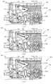
次いで、図32から図43を参照して第1送球経路KR1から第4送球経路KR4を送球される遊技球について説明する。図32から図34は、中間部材330及び後方部材350の断面図である。   Next, with reference to FIG. 32 to FIG. 43, a description will be given of a game ball that is sent from the first pitch route KR1 to the fourth pitch route KR4. 32 to 34 are cross-sectional views of the intermediate member 330 and the rear member 350.

なお、図32から図34及び図38から図40は、図31(a)の断面と対応し、図35から図37及び図41から図43は、図31(b)の断面と対応する。また、図32から図34及び図35から図37は、第1送球経路KR1及び第3送球経路KR3を送球される遊技球の遷移状態が図示され、図38から図40及び図41から図43では、第2送球経路KR2及び第4送球経路KR4を送球される遊技球の遷移状態が図示される。   32 to 34 and FIGS. 38 to 40 correspond to the cross section of FIG. 31A, and FIGS. 35 to 37 and FIGS. 41 to 43 correspond to the cross section of FIG. 31B. FIGS. 32 to 34 and FIGS. 35 to 37 illustrate transition states of game balls that are sent through the first pitching route KR1 and the third pitching route KR3. FIGS. 38 to 40 and FIGS. Then, the transition state of the game balls sent through the second pitching route KR2 and the fourth pitching route KR4 is illustrated.

図32及び図35に示すように、後方部材350の可変板352が第1回転状態の場合に、中間部材330の受部331aの上部を転動して送球される遊技球は、第1送球経路KR1に送球される。即ち、中間部材330の受部331aの上部を転動して送球される遊技球は、中間部材330と背面本体部351との対向間の隙間に流下される。   As shown in FIGS. 32 and 35, when the variable plate 352 of the rear member 350 is in the first rotation state, the game ball that is sent by rolling on the upper portion of the receiving portion 331a of the intermediate member 330 is the first throwing ball. The ball is sent to the route KR1. In other words, the game ball that rolls and moves on the upper portion of the receiving portion 331 a of the intermediate member 330 flows down into a gap between the intermediate member 330 and the back main body portion 351.

図32及び図35に示す状態から、第1送球経路KR1を流下する遊技球は、中間部材330の外側案内部331b2の上面に流下し、図33及び図36に示すように、外側案内部331b2の上面を転動して、第3送球経路KR3に送球される。なお、上述したように、外側案内部331b2は、左右方向中央部から外側に向かうに従って、下降傾斜して形成されるので、正面視において、第1送球経路KR1の左側を流下する遊技球は左側の第3送球経路KR3に送球され、第1送球経路KR1の右側を流下する遊技球は右側の第3送球経路KR3に送球される。   From the state shown in FIGS. 32 and 35, the game ball flowing down the first pitching path KR1 flows down to the upper surface of the outer guide part 331b2 of the intermediate member 330, and as shown in FIGS. 33 and 36, the outer guide part 331b2 Is rolled onto the third pitching path KR3. Note that, as described above, the outer guide portion 331b2 is formed so as to descend downward from the central portion in the left-right direction, so that the game ball flowing down the left side of the first pitching path KR1 is the left side when viewed from the front. The game balls that are sent to the third pitching route KR3 and flow down the right side of the first pitching route KR1 are sent to the third pitching route KR3 on the right side.

図33及び図36に示す状態から、第3送球経路KR3に送球される遊技球は、図34及び図37に示すように、第3送球経路KR3を流下して、後述する背面ベース390を介して可変ユニット360に送球される。   The game balls sent to the third pitching path KR3 from the state shown in FIGS. 33 and 36 flow down the third pitching path KR3 and pass through the back base 390 described later, as shown in FIGS. To the variable unit 360.

図38及び図41に示すように、後方部材350の可変板352が第3回転状態の場合に、中間部材330の受部331aの上部を転動して送球される遊技球は、第2送球経路KR2に送球される。即ち、中間部材330の受部331aの上部を転動して送球される遊技球は、後方部材350の可変板352の上部を転動して、第2送球経路KR2に送球される。   As shown in FIGS. 38 and 41, when the variable plate 352 of the rear member 350 is in the third rotation state, the game ball that is sent by rolling on the upper portion of the receiving portion 331a of the intermediate member 330 is the second throwing ball. The ball is sent to the route KR2. In other words, the game ball that is rolled by the upper part of the receiving part 331a of the intermediate member 330 rolls on the upper part of the variable plate 352 of the rear member 350 and is sent to the second pitching path KR2.

図38及び図41に示す状態から、第3送球経路KR3を流下する遊技球は、入賞部材353の第2検出孔353bの内部を通過して、図39及び図42に示すように、前側開口353cから排出され第4送球経路KR4に送球される。   From the state shown in FIG. 38 and FIG. 41, the game ball flowing down the third pitching path KR3 passes through the inside of the second detection hole 353b of the winning member 353, and as shown in FIG. 39 and FIG. It is discharged from 353c and sent to the fourth pitching route KR4.

この場合、上述したように、中間部材330の受部331aの基部は、重力方向(図31(a)上下方向)の高さ位置が第1回転状態における可変板352の重力方向略中央位置と略同一の高さ位置に設定されるので、中間部材330と背面本体部351との対向間を流下する第1送球経路KR1と背面本体部351の開口351bの内側を送球させる第2送球経路KR2とを可変板352の変位状態で経路を変更する際の中間部材330及び後方部材350の重力方向の距離寸法を小さくできる。   In this case, as described above, the base portion of the receiving portion 331a of the intermediate member 330 has a height position in the gravity direction (a vertical direction in FIG. 31 (a)) that is substantially the center position in the gravity direction of the variable plate 352 in the first rotation state. Since they are set at substantially the same height position, the first pitching path KR1 flowing down between the intermediate member 330 and the back body part 351 and the second pitching path KR2 that feeds the inside of the opening 351b of the back body part 351. The distance dimension in the gravity direction of the intermediate member 330 and the rear member 350 when the path is changed while the variable plate 352 is displaced can be reduced.

即ち、中間部材330の受部331aを転動する遊技球を、背面側に配設される可変板352で第1送球経路KR1と第2送球経路KR2とに振り分ける際に、第3状態において可変板352の軸部352aから遠方の端部を受部331aの基部よりも低くすることで、可変板352の配設位置を重力方向に高くすることができる。その結果、中間部材330及び後方部材350の重力方向の距離寸法を小さくすることができる。   That is, when the game ball rolling on the receiving portion 331a of the intermediate member 330 is distributed to the first pitching path KR1 and the second pitching path KR2 by the variable plate 352 provided on the back side, the variable in the third state. By setting the end portion of the plate 352 far from the shaft portion 352a to be lower than the base portion of the receiving portion 331a, the disposition position of the variable plate 352 can be increased in the direction of gravity. As a result, the distance dimension in the gravity direction between the intermediate member 330 and the rear member 350 can be reduced.

図39及び図42に示す状態から、第4送球経路KR4に送球される遊技球は、図40及び図43に示すように、第4送球経路KR4の中間部材330の内側案内部331b1の上面を転動して送球され、後述する回転送球部370に送球される。なお、上述したように、内側案内部331b1は、左右方向中央部から外側に向かうに従って、下降傾斜して形成されるので、正面視において、第2送球経路KR2の左側を流下する球(左側の第2検出孔353bを通過して左側の前側開口353cから排出される球)は左側の第4送球経路KR4に送球され、第2送球経路KR2の右側を流下する球(右側の第2検出孔353bを通過して右側の前側開口353cから排出される球)は右側の第4送球経路KR4に送球される。   From the state shown in FIG. 39 and FIG. 42, the game ball sent to the fourth pitching route KR4 is placed on the upper surface of the inner guide portion 331b1 of the intermediate member 330 of the fourth pitching route KR4 as shown in FIGS. The ball is rolled and sent to a round transfer ball unit 370 to be described later. Note that, as described above, the inner guide portion 331b1 is formed to be inclined downward as it goes outward from the central portion in the left-right direction. Therefore, in a front view, the sphere (on the left side) flows down the left side of the second pitching path KR2. A ball passing through the second detection hole 353b and discharged from the left front opening 353c) is sent to the left fourth throwing path KR4 and flows down the right side of the second throwing path KR2 (right second detection hole). Sphere passing through 353b and discharged from the right front opening 353c) is sent to the right fourth pitching path KR4.

次に、図44から図51を参照して、中間部材330の受部331aを転動して第1送球経路KR1及び第2送球経路KR2に送球される遊技球について説明する。図44及び図45は、中間部材330及び後方部材350の断面図である。なお、図44及び図45は、図31(a)の断面に対応する。   Next, with reference to FIG. 44 to FIG. 51, a description will be given of the game balls that roll on the receiving portion 331a of the intermediate member 330 and are sent to the first pitching route KR1 and the second pitching route KR2. 44 and 45 are cross-sectional views of the intermediate member 330 and the rear member 350. FIG. 44 and 45 correspond to the cross section of FIG.

図44及び図45に示すように、中間部材330の受部331aの上面を転動して送球される遊技球は、背面側に転動して可変板352と当接して第1送球経路KR1に送球される。   As shown in FIGS. 44 and 45, the game ball that is sent by rolling on the upper surface of the receiving portion 331a of the intermediate member 330 rolls to the rear side and comes into contact with the variable plate 352 to contact the first pitching path KR1. Is sent to.

この場合、上述したように、第1回転状態における可変板352は、正面部352d2が、軸部352aから離間するに従って前方に傾倒して配置されるので、受部331aから第1送球経路KR1に送球される遊技球を、正面部352d2に衝突させて下方に流下させやすくできる。   In this case, as described above, the variable plate 352 in the first rotation state is disposed such that the front portion 352d2 is tilted forward as it is separated from the shaft portion 352a, and thus the receiving portion 331a moves to the first pitching path KR1. The game ball to be sent can collide with the front portion 352d2 and easily flow down.

また、膨出部352d1の正面部351d2と連結される部分は、受部331aの基端よりも遊技球の半径分上方に位置されるので、球が受部331aを勢いよく転動する際には、球を膨出部352d1に衝突させて下方に流下させることができる。この際、比較的送球の勢いが付いた遊技球を、板部352dから膨出する膨出部352d1に衝突させることで、板部352dの破損を抑制できる。即ち、球の転動速度が比較的速い場合には、膨出する分、剛性の高い膨出部352d1と衝突させることで、板部352dの破損を防ぐことができる。   In addition, the portion connected to the front portion 351d2 of the bulging portion 352d1 is positioned above the base end of the receiving portion 331a by the radius of the game ball, so when the ball rolls vigorously on the receiving portion 331a. The ball can collide with the bulging portion 352d1 and can flow downward. At this time, the game ball having a relatively high momentum for ball feeding is caused to collide with the bulging portion 352d1 that bulges from the plate portion 352d, so that the breakage of the plate portion 352d can be suppressed. That is, when the rolling speed of the sphere is relatively high, the plate portion 352d can be prevented from being damaged by colliding with the bulging portion 352d1 having high rigidity for the amount of bulging.

次いで、図46から図51を参照して可変板352が第1回転状態から第3回転状態へ変位する際に、球が中間部材330の受部331aの上面を転動して送球される場合について説明する。図46から図51は、中間部材330及び後方部材350の断面図である。なお、図46から図48及び図49から図51は、図31(a)の断面に対応する。また、図46から図48及び図49から図51では、可変板352が第1回転状態から第3回転状態に変位する際の遊技球の転動状態が図示される。   Next, when the variable plate 352 is displaced from the first rotation state to the third rotation state with reference to FIGS. 46 to 51, the ball rolls on the upper surface of the receiving portion 331 a of the intermediate member 330 and is sent. Will be described. 46 to 51 are cross-sectional views of the intermediate member 330 and the rear member 350. 46 to 48 and FIGS. 49 to 51 correspond to the cross section of FIG. 46 to 48 and FIGS. 49 to 51 illustrate the rolling state of the game ball when the variable plate 352 is displaced from the first rotation state to the third rotation state.

ここで、上述したように、第3状態において可変板352の軸部352aから遠方の端部を受部331aの基部よりも低くすると、受部331aの基部と変位動作中の可変板352との間に遊技球を挟み込んで不具合を起こす可能性があった。   Here, as described above, when the end portion far from the shaft portion 352a of the variable plate 352 is set lower than the base portion of the receiving portion 331a in the third state, the base portion of the receiving portion 331a and the variable plate 352 during the displacement operation There was a possibility that a game ball could be caught between them, causing problems.

これに対し、本実施形態では、図46及び図49に示すように、中間部材330の受部331aの基部が、重力方向(図31(a)上下方向)の高さ位置が第1回転状態における可変板352の重力方向略中央位置と略同一の高さ位置に設定されるので、変位途中の可変板352が受部331aとの間に遊技球を挟み込んだ際の遊技球と膨出部352d1との当接位置を受部331aの基端と遊技球の中心とを連結する仮想線S2で分割する遊技球の正面側または背面側のどちらか一方とすることができ、球が受部331aの基部と可変板352との間に挟まることを抑制できる。   On the other hand, in the present embodiment, as shown in FIGS. 46 and 49, the base portion of the receiving portion 331a of the intermediate member 330 has a height position in the gravity direction (vertical direction in FIG. 31 (a)) in the first rotation state. Is set at a height position substantially the same as the center position in the gravity direction of the variable plate 352, so that the game ball and the bulging portion when the variable plate 352 in the middle of displacement sandwiches the game ball between the receiving portion 331a The contact position with 352d1 can be either the front side or the back side of the game ball divided by a virtual line S2 connecting the base end of the receiving portion 331a and the center of the game ball, and the ball is the receiving portion. It is possible to suppress pinching between the base portion of 331a and the variable plate 352.

即ち、図46から図48に示すように、仮想線S2で分割される遊技球の正面側と膨出部352d1とが当接する場合には、膨出部352d1の正面部352d2との連結側が遊技球と衝突する。よって、膨出部352d1の湾曲面を利用して、図48に示すように、球を第1送球経路KR1に送球することができる。   That is, as shown in FIGS. 46 to 48, when the front side of the game ball divided by the virtual line S2 comes into contact with the bulging portion 352d1, the connection side of the bulging portion 352d1 with the front portion 352d2 is the game side. Collide with a sphere. Therefore, using the curved surface of the bulging portion 352d1, it is possible to send a ball to the first pitching route KR1, as shown in FIG.

一方、図49から図51に示すように、仮想線S2で分割される遊技球の背面側と膨出部352d1とが当接する場合には、膨出部352d1の軸部352aから離間する側の湾曲面と当接される。これにより、受部331aから落下しようとする遊技球を可変板352の変位を利用して、正面側に押し戻すことができる。これにより、可変板352を第3回転状態に変位させて、球を第2送球経路KR2に案内できる。   On the other hand, as shown in FIGS. 49 to 51, when the back side of the game ball divided by the virtual line S2 and the bulging portion 352d1 are in contact with each other, the side of the bulging portion 352d1 on the side away from the shaft portion 352a. It abuts on the curved surface. Thereby, the game ball about to fall from the receiving portion 331a can be pushed back to the front side using the displacement of the variable plate 352. Thereby, the variable plate 352 is displaced to the third rotation state, and the ball can be guided to the second pitching path KR2.

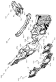
次いで、図52から図54を参照して、背面ベース390の詳細な説明をする。図52(a)は、背面ベース390の正面図であり、図52(b)は、背面ベース390の側面図である。図53は、背面ベース390の分解正面斜視図である。図54は、背面ベース390の分解背面斜視図である。   Next, the back base 390 will be described in detail with reference to FIGS. 52 to 54. 52A is a front view of the back base 390, and FIG. 52B is a side view of the back base 390. FIG. FIG. 53 is an exploded front perspective view of the back base 390. 54 is an exploded rear perspective view of the rear base 390. FIG.

図52から図54に示すように、背面ベース390は、背面側に配置される板状体の背面板391と、背面板391の重力方向下側の一端に配置され背面板391との対向間に駆動手段のソレノイド397を保持する保持部材392と、その保持部材392の両端に締結される2の円環部材394と、その2の円環部材394の対向間の外側に配設されるストッパ部396とを主に備えて形成される。   As shown in FIGS. 52 to 54, the back surface base 390 is disposed between the back plate 391 of the plate-like body disposed on the back surface and the back plate 391 disposed at one end on the lower side in the gravity direction of the back surface plate 391. A holding member 392 for holding the solenoid 397 of the driving means, two annular members 394 fastened to both ends of the holding member 392, and a stopper disposed on the outer side between the two annular members 394 facing each other. A portion 396 is mainly provided.

背面板391は、正面視略台形の板状体から形成される。背面板391は、上述した後方部材350の背面側を覆設する板であり、後方部材350の正面視における外形と略同一の外形に形成される。   The back plate 391 is formed from a plate-like body that is substantially trapezoidal in front view. The rear plate 391 is a plate that covers the rear side of the rear member 350 described above, and is formed to have an outer shape that is substantially the same as the outer shape of the rear member 350 in a front view.

ソレノイド397は、後述するストッパ部396に駆動力を付与する駆動手段であり、ストッパ部396に駆動力を伝達する伝達部397aを備える。また、ソレノイド397は、2のストッパ部396の背面側にそれぞれ配設される。   The solenoid 397 is a driving unit that applies a driving force to a stopper unit 396 described later, and includes a transmission unit 397 a that transmits the driving force to the stopper unit 396. The solenoids 397 are disposed on the back side of the two stopper portions 396, respectively.

伝達部397aは、ソレノイド397に電力が供給されることで、重力方向に変位する突起であり、後述するストッパ部396の第1係合部396a及び第2係合部396bの間に挿入される。   The transmission portion 397a is a protrusion that is displaced in the direction of gravity when electric power is supplied to the solenoid 397, and is inserted between a first engagement portion 396a and a second engagement portion 396b of a stopper portion 396 described later. .

保持部材392は、正面視横長矩形に形成され、長手方向の両端部に正面側に凹設される凹部392aと、凹部392aに正面から背面に亘って貫通形成される開口392bと、を備えて形成される。   The holding member 392 is formed in a rectangular shape when viewed from the front, and includes a recess 392a that is recessed at the front side at both ends in the longitudinal direction, and an opening 392b that is formed through the recess 392a from the front to the back. It is formed.

凹部392aは、内側にソレノイド397を挿入する凹みであり、ソレノイド397の外形形状に凹設される。よって、凹部392aにソレノイド397を挿入した後に保持部材392を背面板391に取着することで、ソレノイド397を脱落不能に保持できる。   The recess 392a is a recess into which the solenoid 397 is inserted, and is recessed in the outer shape of the solenoid 397. Therefore, by attaching the holding member 392 to the back plate 391 after inserting the solenoid 397 into the recess 392a, the solenoid 397 can be held so as not to fall off.

開口392bは、ソレノイド397の伝達部397aを前方に挿通させる開口であり、伝達部397aよりも大きい正面視縦長矩形の開口に形成される。よって、凹部392aの内側にソレノイド397を配置すると、ソレノイド397の伝達部397aが正面側に突出される。   The opening 392b is an opening through which the transmission part 397a of the solenoid 397 is inserted forward, and is formed in an opening that is larger than the transmission part 397a and has a rectangular shape in front view. Therefore, when the solenoid 397 is disposed inside the recess 392a, the transmission portion 397a of the solenoid 397 protrudes to the front side.

円環部材394は、第3送球経路KR3から遊技球が送球される送球部であり、側面視略円環形状に形成され、軸心に貫通する軸支孔394aを備える。軸支孔394aは、後述する軸B1を回転可能に保持する孔であり、軸B1の外径よりも大きい内径に形成される。   The annular member 394 is a ball feeding portion through which game balls are fed from the third ball feeding path KR3, and is formed in a substantially annular shape when viewed from the side, and includes a shaft support hole 394a penetrating the shaft center. The shaft support hole 394a is a hole that rotatably holds a shaft B1, which will be described later, and is formed with an inner diameter larger than the outer diameter of the shaft B1.

軸B1は、円柱状に形成され、一端が上述したように、円環部材394の軸支孔394aに挿入されると共に、他端が後述するストッパ部396の軸孔396cに外嵌される。よって、軸B1は、ストッパ部396の回転変位に伴って、軸支孔394aに対して回転変位することができる。   The shaft B1 is formed in a columnar shape, and one end is inserted into the shaft support hole 394a of the annular member 394 as described above, and the other end is externally fitted into a shaft hole 396c of a stopper portion 396 described later. Therefore, the shaft B1 can be rotationally displaced with respect to the shaft support hole 394a with the rotational displacement of the stopper portion 396.

ストッパ部396は、回転変位することで後述する可変ユニット460の送球経路KR6を送球不能にする送球経路遮断手段であり、側面視略三角形状に形成され、2の円環部材394の対向間の外側に配設される。   The stopper portion 396 is a pitching path blocking means that disables pitching of a pitching path KR6 of the variable unit 460, which will be described later, by being rotationally displaced. The stopper section 396 is formed in a substantially triangular shape when viewed from the side. Arranged outside.

また、ストッパ部396は、円環部材394の軸方向に略円形状に貫通する軸孔396cと、その軸孔396cの軸から径方向外側に突出する第1係合部396a及び第2係合部396bとを主に備えて形成される。   The stopper portion 396 includes a shaft hole 396c that penetrates in a substantially circular shape in the axial direction of the annular member 394, and a first engagement portion 396a and a second engagement portion that project radially outward from the shaft of the shaft hole 396c. The portion 396b is mainly provided.

第1係合部396aは、上述したソレノイド397の伝達部397aと係合して、ソレノイド397の駆動力が伝達される突起であり、伝達部397aの重力方向上側に位置して配設される。   The first engagement portion 396a is a protrusion that engages with the transmission portion 397a of the solenoid 397 described above to transmit the driving force of the solenoid 397, and is disposed on the upper side in the gravity direction of the transmission portion 397a. .

第2係合部396bは、第1係合部396aと同様に、ソレノイド397の伝達部397aと係合して、ソレノイド397の駆動力が伝達される突起であり、伝達部材397bの重力方向下側に位置して配設される。   Similar to the first engagement portion 396a, the second engagement portion 396b is a protrusion that engages with the transmission portion 397a of the solenoid 397 to transmit the driving force of the solenoid 397, and is below the gravity direction of the transmission member 397b. Located on the side.

なお、第1係合部396aと第2係合部396bとは、軸孔396cの軸周りに所定の隙間を備えて形成されており、突出先端側の互いの距離寸法は、ソレノイド397の伝達部397aの上下方向寸法よりも大きく設定される。これにより、第1係合部396aと第2係合部396bとの間にソレノイド397の伝達部397aを挿入して、ストッパ部396に駆動力を伝達することができる。   The first engaging portion 396a and the second engaging portion 396b are formed with a predetermined gap around the shaft hole 396c, and the distance between the projecting tips is determined by the transmission of the solenoid 397. It is set larger than the vertical dimension of the portion 397a. Thereby, the transmission part 397a of the solenoid 397 can be inserted between the first engagement part 396a and the second engagement part 396b, and the driving force can be transmitted to the stopper part 396.

次に、図55を参照して、ストッパ部396の遷移について説明する。図55(a)から図55(c)は、図52のLV−LV線における背面ベース390の断面図である。なお、図55の(a)から図55(c)では、ストッパ部396の遷移状態が図示される。また、図55では、ストッパ部396の軸孔396cから遠方の端部を端部A2の符号を付して説明する。   Next, transition of the stopper portion 396 will be described with reference to FIG. FIG. 55A to FIG. 55C are cross-sectional views of the back surface base 390 taken along the line LV-LV in FIG. 55A to 55C, the transition state of the stopper portion 396 is illustrated. In FIG. 55, the end portion far from the shaft hole 396c of the stopper portion 396 will be described with reference to the end portion A2.

図55(a)に示すように、ソレノイド397の伝達部397aが下方に位置する第1遮断状態では、伝達部397aが、ストッパ部396の第2係合部396bと当接して、ストッパ部396の端部A2が上方に変位する(図55(a)では、軸孔396cの軸周りに端部A2が右回転する)方向に駆動力が作用される。これにより、端部A2が軸孔396cよりも重力方向上側に位置される。   As shown in FIG. 55A, in the first shut-off state where the transmission portion 397a of the solenoid 397 is positioned below, the transmission portion 397a contacts the second engagement portion 396b of the stopper portion 396, and the stopper portion 396 A driving force is applied in a direction in which the end A2 of the first end is displaced upward (in FIG. 55A, the end A2 rotates clockwise around the axis of the shaft hole 396c). Thus, the end A2 is positioned above the shaft hole 396c in the gravity direction.

図55(a)に示す状態から、ソレノイド397の伝達部397aが上方に変位され、図55(b)に示す伝達部397aが全変位量の中間位置まで変位される第2遮断状態では、伝達部397aが、ストッパ部396の第1係合部396aと当接して、ストッパ部396の端部A2が下方に変位する(図55(b)では、軸孔396cの軸周りに端部A2が左回転する)方向に駆動力が作用される。これにより、端部A2が、第1遮断状態よりも軸孔396cと重力方向の高さが近くされる。   From the state shown in FIG. 55 (a), the transmission part 397a of the solenoid 397 is displaced upward, and the transmission part 397a shown in FIG. 55 (b) is displaced to the middle position of the total displacement amount. The portion 397a comes into contact with the first engaging portion 396a of the stopper portion 396, and the end portion A2 of the stopper portion 396 is displaced downward (in FIG. 55 (b), the end portion A2 is arranged around the shaft hole 396c. A driving force is applied in the direction of left rotation. As a result, the end portion A2 is closer to the shaft hole 396c in the gravity direction than in the first blocking state.

図55(b)に示す状態から、ソレノイド397の伝達部397aが更に上方に変位され、図55(c)に示す伝達部397aが終端まで変位された第3遮断状態では、伝達部397aが、ストッパ部396の第1係合部396aと当接して、ストッパ部396の端部A2が下方に変位する(図55(b)では、軸孔396cの軸周りに端部A2が左回転する)方向に駆動力が作用される。この場合、端部A2が、軸孔396cの軸の重力方向の高さと略同一の高さ位置に変位される。   From the state shown in FIG. 55 (b), the transmission part 397a of the solenoid 397 is further displaced upward, and in the third cutoff state where the transmission part 397a shown in FIG. The end A2 of the stopper 396 is displaced downward by coming into contact with the first engagement portion 396a of the stopper 396 (in FIG. 55B, the end A2 rotates counterclockwise around the axis of the shaft hole 396c). A driving force is applied in the direction. In this case, the end A2 is displaced to a height position substantially the same as the height of the shaft hole 396c in the direction of gravity.

一方、第3遮断状態から第1遮断状態に変位する際には、ソレノイド397の伝達部397aが第2係合部396bを下方に押し下げることで、先端部A1が軸孔396cの軸周りに押し上げられる。   On the other hand, when displacing from the third cutoff state to the first cutoff state, the transmission portion 397a of the solenoid 397 pushes the second engagement portion 396b downward, so that the tip end portion A1 is pushed up around the shaft hole 396c. It is done.

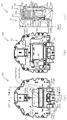
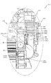
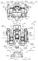
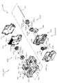
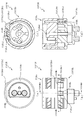
次いで、図56から図58を参照して、可変ユニット360の本体部380について説明する。図56(a)は、可変ユニット360の正面図であり、図56(b)は、可変ユニット360の上面図である。図57は、可変ユニット360の本体部380の分解正面斜視図である。図58は、可変ユニット360の本体部380の分解背面斜視図である。   Next, the main body 380 of the variable unit 360 will be described with reference to FIGS. 56 to 58. 56A is a front view of the variable unit 360, and FIG. 56B is a top view of the variable unit 360. FIG. 57 is an exploded front perspective view of the main body 380 of the variable unit 360. 58 is an exploded rear perspective view of the main body 380 of the variable unit 360. FIG.

可変ユニット360は、第3送球経路KR3及び第4送球経路KR4から送球された遊技球を正面側に送球する経路を備える本体部380と、回転する回転体に遊技球を吸着させて遊技球を送球する回転送球部370とを主に備えて形成される。   The variable unit 360 includes a main body 380 having a path for sending the game balls sent from the third ball feeding path KR3 and the fourth ball feeding path KR4 to the front side, and a rotating rotator to attract the game balls to the game balls. It is mainly provided with a round transfer ball portion 370 for sending a ball.

本体部380は、上述したセンターフレーム310の重力方向下側の一側の背面に配置され、センターフレーム310の中央開口を通じて遊技者から視認可能とされる(図8参照)。本体部380は、上面に遊技球の転動面が形成される上面ベース381と、その上面ベース381に対向して配設される第1下面ベース383と、上面ベース381及び第1下面ベース383との間に一端が軸支されて変位可能に配置されるV入賞部材382と、そのV入賞部材382に駆動力を付与する第1駆動モータM1と、その第1駆動モータM1の駆動力をV入賞部材382に伝達する第1伝達手段384と、本体部380に回転可能に配設される振分部389と、その振分部389に駆動力を付与する第2駆動モータM2と、その第2駆動モータM2の駆動力を振分部389に伝達する第2伝達手段387とを主に備えて形成される。   The main body 380 is disposed on the back surface on the lower side in the gravity direction of the center frame 310 described above, and is visible to the player through the central opening of the center frame 310 (see FIG. 8). The main body 380 includes an upper surface base 381 on which a rolling surface of a game ball is formed on the upper surface, a first lower surface base 383 disposed to face the upper surface base 381, and the upper surface base 381 and the first lower surface base 383. V winning member 382 that is pivotally disposed at one end between the first driving motor M1, a first driving motor M1 that applies a driving force to the V winning member 382, and a driving force of the first driving motor M1. A first transmission means 384 for transmitting to the V winning member 382, a distributing portion 389 rotatably disposed on the main body 380, a second drive motor M2 for applying a driving force to the distributing portion 389, and The second transmission means 387 for transmitting the driving force of the second drive motor M2 to the distributing unit 389 is mainly provided.

上面ベース381は、上述したように、第3送球経路KR3および第4送球経路KR4から送球される遊技球を送球される転動面を備える板部材であり、上面視略矩形の板状体から形成される。上面ベース381は、背面側から正面側に亘って凹設される2の第1転動部381aと、その第1転動部381aの背面側を取り囲んで立設される立設部381bと、転動部381aの前後方向中央部から分岐して凹設される第2転動部381cと、その第2転動部381cの正面側に回転体372R,372Lとを挟む位置に形成される第3転動部381dと、その第3転動部381dと隣り合って形成されると共に第1転動部381aが連結される第4転動部381eと、第2転動部381cの基部側の第1転動部381aを挟んだ位置に動重力方向に開口される軸支孔381fとを主に備えて形成される。   As described above, the upper surface base 381 is a plate member having a rolling surface to which game balls sent from the third ball feeding path KR3 and the fourth ball feeding path KR4 are sent, and is formed from a plate-like body having a substantially rectangular shape when viewed from above. It is formed. The upper surface base 381 includes two first rolling parts 381a that are recessed from the back side to the front side, and a standing part 381b that stands up to surround the back side of the first rolling part 381a. A second rolling part 381c that is branched and recessed from the center part in the front-rear direction of the rolling part 381a, and a second part that is formed at a position sandwiching the rotating bodies 372R and 372L on the front side of the second rolling part 381c. A third rolling part 381d, a fourth rolling part 381e formed adjacent to the third rolling part 381d and connected to the first rolling part 381a, and a base part side of the second rolling part 381c. It is mainly provided with a shaft support hole 381f opened in the direction of dynamic gravity at a position sandwiching the first rolling portion 381a.

第1転動部381aは、第4送球経路KR4を送球される遊技球が送球される送球経路であり、第4送球経路KR4から遊技球が送球される背面側の端部から正面側に向かって下降傾斜して形成される。これにより、第4送球経路KR4を送球される遊技球を正面側に送球する第5送球経路KR5が形成される。   The first rolling portion 381a is a pitching route through which a game ball sent through the fourth pitching route KR4 is sent. The first rolling portion 381a faces the front side from the rear end where the game ball is sent from the fourth pitching route KR4. It is formed to be inclined downward. As a result, a fifth pitching path KR5 is formed for pitching the game balls sent on the fourth pitching path KR4 to the front side.

また、上述したように第4送球経路KR4は、左右方向に2つに分流されており、第1転動部381aは、2の第4送球経路KR4の重力方向下側にそれぞれ形成される。これにより、それぞれの第4送球経路KR4が、それぞれの第5送球経路KR5と連結される。   Further, as described above, the fourth pitching path KR4 is divided into two in the left-right direction, and the first rolling portion 381a is formed on the lower side in the gravity direction of the second fourth pitching path KR4. Thereby, each 4th pitching path | route KR4 is connected with each 5th pitching path | route KR5.

2の第1転動部381aは、それぞれ正面側に延設されると共に、第4転動部381eと連結される手前で合流して、1の転動面とされる。   Each of the second first rolling portions 381a extends to the front side, and merges before being connected to the fourth rolling portion 381e to form one rolling surface.

立設部381bは、第4送球経路KR4から送球される遊技球を、第1転動部381aに案内する壁であり、立設先端部(重力方向上側端部)が、上述する中間部材330の案内部330bと当接して配設される。これにより、第4送球経路KR4を流下する遊技球を確実に第1転動部381aの第5送球経路KR5に送球できる。   The standing portion 381b is a wall that guides the game ball sent from the fourth pitching route KR4 to the first rolling portion 381a, and the standing tip portion (the upper end portion in the gravity direction) is the intermediate member 330 described above. Is disposed in contact with the guide portion 330b. Thereby, the game ball flowing down the fourth pitching route KR4 can be reliably sent to the fifth pitching route KR5 of the first rolling part 381a.

第2転動部381cは、背面側から正面側にかけて延設される第1転動部381aの略中央位置から、上面ベース381の外側に延設される面であり、第1転動部381aよりも下方に形成されると共に、上面ベース381の外側に向かうに従って下降傾斜して形成される。よって、第1転動部381aの上部を転動して正面側に送球される遊技球を、後述する振分部389に衝突させて第2転動部381cに送球させることができる。   The second rolling portion 381c is a surface that extends from the substantially central position of the first rolling portion 381a that extends from the back side to the front side, and extends outside the upper surface base 381. The first rolling portion 381a In addition, it is formed so as to be inclined downward toward the outside of the upper surface base 381. Therefore, a game ball that rolls on the upper side of the first rolling part 381a and is sent to the front side can collide with a sorting part 389, which will be described later, and be sent to the second rolling part 381c.

また、第2転動部381cは、上述したように左右方向外側に向かうに従って下降傾斜して形成されるので、第2転動部381cに送球される遊技球は、第1転動部381aから離間する方向に転動して送球される。即ち、第2転動部381cにより、球が送球される第6送球経路KR6が形成される。   Further, as described above, the second rolling portion 381c is formed so as to be inclined downward toward the outer side in the left-right direction, so that the game ball sent to the second rolling portion 381c is from the first rolling portion 381a. Rolled in the direction of separation and sent. That is, the second rolling portion 381c forms a sixth pitching path KR6 through which a ball is pitched.

第2転動部381cは、延設方向と直交する方向の中央位置が凹んだ形状に形成されており、第2転動部381cを転動する遊技球が揺れ動きにくくされる。これにより、第6送球経路KR6を送球される遊技球を安定させることができる。   The second rolling portion 381c is formed in a shape in which the center position in the direction orthogonal to the extending direction is recessed, and the game ball rolling on the second rolling portion 381c is hardly shaken. Thereby, it is possible to stabilize the game ball sent through the sixth pitching route KR6.

第3転動部381dは、後述する回転体372R,372Lにより送球される遊技球を受ける面であり、回転体372R,372Lの隣りに形成されると共に、第4転動部381e(正面側)に向かって下降傾斜して形成される。よって、回転体372R,372Lから第3転動部381dの上面に送球される遊技球は、第3転動部381dの上面を転動して第4転動部381eに送球される。即ち、第3転動部381dにより、第4転動部381eに遊技球を送球する第7送球経路KR7が形成される。   The third rolling portion 381d is a surface that receives a game ball sent by a rotating body 372R, 372L, which will be described later, and is formed adjacent to the rotating bodies 372R, 372L, and the fourth rolling portion 381e (front side). It is formed so as to be inclined downward. Therefore, the game balls sent from the rotating bodies 372R and 372L to the upper surface of the third rolling part 381d roll on the upper surface of the third rolling part 381d and are sent to the fourth rolling part 381e. That is, the third rolling part 381d forms a seventh pitching path KR7 for feeding a game ball to the fourth rolling part 381e.

第4転動部381eは、第3転動部381d及び第1転動部381aを転動される遊技球を、正面側に落下させるための傾斜面であり、第3転動部381d及び第1転動部381aよりも重力方向において低い位置に形成されると共に、正面側に向かって下降傾斜して形成される。これにより、第3転動部381d及び第1転動部381aから送球される遊技球を第4転動部381eの上面にスムーズに転動させて、第4転動部381eの正面側に転動させることができる。即ち、第4転動部381eにより、第1転動部381a及び第3転動部381dから送球される遊技球を本体部380の正面側に流下させる第8送球経路KR8が形成される。   The fourth rolling portion 381e is an inclined surface for dropping the game balls rolled on the third rolling portion 381d and the first rolling portion 381a to the front side, and the third rolling portion 381d and the third rolling portion 381d It is formed at a position lower in the direction of gravity than the first rolling part 381a and is inclined downward toward the front side. As a result, the game balls sent from the third rolling part 381d and the first rolling part 381a are smoothly rolled on the upper surface of the fourth rolling part 381e, and rolled to the front side of the fourth rolling part 381e. Can be moved. That is, the eighth rolling path KR8 is formed by the fourth rolling section 381e to allow the game balls sent from the first rolling section 381a and the third rolling section 381d to flow down to the front side of the main body section 380.

軸支孔381fは、本体部380の両側に形成される2の第2転動部381cの対向間中間位置に重力方向に貫通して形成される。   The shaft support hole 381f is formed penetrating in the gravity direction at an intermediate position between the two second rolling portions 381c formed on both sides of the main body 380.

V入賞部材382は、上面ベース381の第4転動部381eから正面側に送球される遊技球の一部をV入賞部材382の内部に送球する球受部であり、上方に配置される上面ベース381側が開放する箱状体に形成される。V入賞部材382は、重力方向下側に突出して形成される軸部382cと、その軸部382cを中心に半円形に突出する湾曲部382bとを主に備えて形成される。   The V winning member 382 is a ball receiving portion that sends a part of a game ball sent to the front side from the fourth rolling portion 381e of the upper surface base 381 to the inside of the V winning member 382, and is an upper surface disposed above. The base 381 is formed in a box-like body that is open. The V winning member 382 is mainly formed with a shaft portion 382c that protrudes downward in the direction of gravity and a curved portion 382b that protrudes in a semicircular shape around the shaft portion 382c.

軸部382cは、第1駆動モータM1からの駆動力を伝達する伝達手段の一部に連結される軸部であり、略箱形状に形成されるV入賞部材382の底面から重力方向下側に突出して形成される。よって、V入賞部材382は、第1駆動モータM1から駆動力が付与されることで、軸部382cを軸に回転変位できる。   The shaft portion 382c is a shaft portion that is coupled to a part of the transmission means that transmits the driving force from the first drive motor M1, and extends downward from the bottom surface of the V winning member 382 formed in a substantially box shape in the gravity direction. Protrusively formed. Therefore, the V winning member 382 can be rotationally displaced about the shaft portion 382c as a driving force is applied from the first drive motor M1.

湾曲部382bは、V入賞部材382が軸部382cを軸に回転した際に、本体部380の正面側に隙間が形成されることを抑制する突出部であり、V入賞部材382の周方向両側に軸部382cの軸を中心とする円形に突出して形成される。   The curved portion 382b is a protruding portion that suppresses the formation of a gap on the front side of the main body portion 380 when the V winning member 382 rotates around the shaft portion 382c, and both sides in the circumferential direction of the V winning member 382 And projecting in a circular shape around the axis of the shaft portion 382c.

第1下面ベース383は、上面ベース381の下面に覆設されると共に、正面側の一部が重力方向下側に凹設された凹部383aを備える。   The first lower surface base 383 is provided on the lower surface of the upper surface base 381 and includes a concave portion 383a in which a part on the front side is recessed downward in the gravitational direction.

凹部383aは、上面ベース381と第1下面ベース383との間からV入賞部材382を突出させるための開口を形成する凹みであり、V入賞部材382の重力方向の高さ寸法よりも大きい凹設深さに設定される。これにより、上面ベース381と第1下面ベース383との対向間にV入賞部材382を配置した際に、凹部383aを介してV入賞部材382の一部を突出させることができる。   The recess 383a is a recess that forms an opening for allowing the V winning member 382 to protrude from between the upper surface base 381 and the first lower surface base 383, and is larger than the height dimension of the V winning member 382 in the gravity direction. Set to depth. Thus, when the V winning member 382 is disposed between the upper surface base 381 and the first lower surface base 383, a part of the V winning member 382 can be protruded through the recess 383a.

第1伝達手段384は、第1駆動モータM1に連結される第1ギヤ384aと、V入賞部材382の軸支孔381fに連結される第2ギヤ384bとから形成される。また、第1伝達手段384は、第1下面ベース383と対向して配設されるカバー板385に覆設されて保持される。   The first transmission means 384 is formed by a first gear 384a connected to the first drive motor M1 and a second gear 384b connected to the shaft support hole 381f of the V winning member 382. Further, the first transmission means 384 is covered and held by a cover plate 385 disposed to face the first lower surface base 383.

第1ギヤ384aは、円形に形成されると共に、外周面にギヤ歯384a1が刻設される。第2ギヤ384bは、上面視略扇状に形成される。また、第2ギヤ384bは、外周面に第1ギヤ384aと歯合するギヤ歯384b1が刻設されると共に、ギヤ歯384b1の軸側に重力方向に貫通する貫通孔384b2が形成される。   The first gear 384a is formed in a circular shape, and gear teeth 384a1 are engraved on the outer peripheral surface. The second gear 384b is formed in a substantially fan shape when viewed from above. The second gear 384b is provided with gear teeth 384b1 meshed with the first gear 384a on the outer peripheral surface, and a through hole 384b2 penetrating in the gravity direction is formed on the shaft side of the gear teeth 384b1.

貫通孔384b2は、V入賞部材382の軸部382cに外嵌する孔であり、軸部382cの直径と略同一の内径または小さい内径に形成される。よって、第1駆動モータM1が回転されると、第1ギヤ384aから駆動力が第2ギヤ384bに伝達され、第2ギヤ384bの軸部382cに外嵌される軸部382cが回転されてV入賞部材382が回転される。   The through hole 384b2 is a hole that is fitted around the shaft portion 382c of the V winning member 382, and is formed with an inner diameter that is substantially the same as or smaller than the diameter of the shaft portion 382c. Therefore, when the first drive motor M1 is rotated, the driving force is transmitted from the first gear 384a to the second gear 384b, and the shaft portion 382c that is externally fitted to the shaft portion 382c of the second gear 384b is rotated. The winning member 382 is rotated.

振分部389は、上面ベース381の軸支孔381fに挿通可能な軸部389aと、軸部389aの基部から径方向外側に扇状に膨出する経路切替部390bとを主に備えて形成される。また、振分部389は、2の第2転動部381cの間に配設される。   The distribution portion 389 is mainly formed with a shaft portion 389a that can be inserted into the shaft support hole 381f of the upper surface base 381, and a path switching portion 390b that swells in a fan shape radially outward from the base portion of the shaft portion 389a. The In addition, the distributing unit 389 is disposed between the two second rolling units 381c.

経路切替部390bは、振分部389の変位に伴って、扇状に膨出した一部が第5送球経路KR5上に位置される。これにより、第5送球経路KR5を送球する遊技球を第2転動部381cに送球させることができる。なお、振分部389の詳しい説明は後述する。   A part of the path switching unit 390b swelled in a fan shape with the displacement of the distribution unit 389 is positioned on the fifth pitching path KR5. Thereby, it is possible to cause a game ball that is sent along the fifth pitching route KR5 to be sent to the second rolling portion 381c. A detailed description of the distribution unit 389 will be described later.

軸部389aは、先端が上面ベース381の軸支孔381fに挿通されると共に、第2伝達手段387の一部に連結される。これにより、第2駆動モータM2に駆動力が付与されると、伝達手段387を介して軸部389aが回転される。   The tip of the shaft portion 389a is inserted into the shaft support hole 381f of the upper surface base 381, and is connected to a part of the second transmission means 387. Thereby, when a driving force is applied to the second drive motor M2, the shaft portion 389a is rotated via the transmission means 387.

第2伝達手段387は、第2駆動モータM2に連結される第1ギヤ387aと、振分部389の軸部389aに連結される第2ギヤ387bとから形成される。また、第2伝達手段387は、上面ベース381と対向して配設される第2下面ベース388に覆設されて保持される。   The second transmission means 387 is formed by a first gear 387a connected to the second drive motor M2 and a second gear 387b connected to the shaft portion 389a of the distributing portion 389. Further, the second transmission means 387 is covered and held by a second lower surface base 388 disposed to face the upper surface base 381.

第1ギヤ387aは、円形に形成されると共に、外周面にギヤ歯が刻設される。第2ギヤ387bは、上面視略扇状に形成される。また、第2ギヤ387bは、外周面に第1ギヤ387aと歯合するギヤ歯387b1が刻設されると共に、重力方向に貫通する貫通孔387b2が形成される。   The first gear 387a is formed in a circular shape, and gear teeth are engraved on the outer peripheral surface. The second gear 387b is formed in a substantially fan shape when viewed from above. The second gear 387b has a gear tooth 387b1 that meshes with the first gear 387a on the outer peripheral surface, and a through hole 387b2 that penetrates in the direction of gravity.

貫通孔387b2は、振分部389の軸部389aに外嵌する孔であり、軸部389aの直径と略同一の内径または軸部389aの直径よりも小さい内径に形成される。よって、第2駆動モータM2が回転されると、駆動力が第1ギヤ387aから第2ギヤ387bに伝達され、第2ギヤ387bの軸部389aに外嵌される軸部389aが回転されて振分部389が回転される。   The through hole 387b2 is a hole that is fitted around the shaft portion 389a of the distributing portion 389, and has an inner diameter that is substantially the same as the diameter of the shaft portion 389a or an inner diameter that is smaller than the diameter of the shaft portion 389a. Therefore, when the second drive motor M2 is rotated, the driving force is transmitted from the first gear 387a to the second gear 387b, and the shaft portion 389a that is externally fitted to the shaft portion 389a of the second gear 387b is rotated to vibrate. The minute portion 389 is rotated.

次に、図59から図61を参照して、振分部389の動作について説明する。図59から図61は、振分部389の上面図である。なお、図59から図61では、第2伝達手段387が破線で図示される。また、図59は、図60を初期位置として、振分部389が軸部389aを軸に左回転された状態が、図61は、図60を初期位置として、振分部389が軸部389aを軸に右回転された状態が、それぞれ図示される。   Next, the operation of the allocating unit 389 will be described with reference to FIGS. 59 to 61 are top views of the allocating unit 389. FIG. In FIGS. 59 to 61, the second transmission means 387 is indicated by a broken line. 59 shows the state in which the distribution unit 389 is rotated counterclockwise about the shaft 389a with FIG. 60 as the initial position, and FIG. 61 shows the state where the distribution unit 389 has the shaft 389a with FIG. 60 as the initial position. Each of the states rotated right about the axis is illustrated.

図60に示すように、第2ギヤ387bのギヤ歯387b1が略中央位置で第1ギヤ387aのギヤ歯と歯合する場合、振分部389の経路切替部389bは、左右方向中央線を中心に左右対称な状態とされる。   As shown in FIG. 60, when the gear teeth 387b1 of the second gear 387b mesh with the gear teeth of the first gear 387a at a substantially central position, the path switching unit 389b of the distribution unit 389 is centered on the horizontal center line. Are in a state of being symmetrical.

次に、初期位置から、第2伝達手段387に回転の駆動力が伝達されて、図59に示すように、振分部389が軸部389aを軸に上面視左回転された状態では、経路切替部389bが、正面視右側に位置する状態とされる。   Next, when the rotational driving force is transmitted from the initial position to the second transmission means 387 and the distribution unit 389 is rotated counterclockwise about the shaft 389a as shown in FIG. The switching unit 389b is positioned on the right side when viewed from the front.

この場合、経路切替部389bの左側端部と左側の第5送球経路KR5の左側端部までの距離寸法は、球の直径よりも小さくされる。よって、左側の第5送球経路KR5を送球される遊技球は、第5送球経路KR5を通過することができず、第6送球経路KR6に送球される。一方、振分部389の右側端部と右側の第5送球経路KR5の右側端部までの距離寸法は、球の直径よりも大きくされる。よって、右側の第5送球経路KR5を送球される遊技球は、第6送球経路KR6に送球されず第5送球経路KR5を送球され、第8送球経路KR8に送球される。   In this case, the distance dimension from the left end of the path switching unit 389b to the left end of the fifth fifth pitching path KR5 is made smaller than the diameter of the sphere. Therefore, the game ball sent through the left fifth pitching route KR5 cannot pass through the fifth pitching route KR5 and is sent to the sixth pitching route KR6. On the other hand, the distance between the right end of the allocating portion 389 and the right end of the right fifth throwing path KR5 is made larger than the diameter of the sphere. Therefore, the game balls sent on the right fifth pitching route KR5 are sent to the fifth pitching route KR5 without being sent to the sixth pitching route KR6, and are sent to the eighth pitching route KR8.

図61の状態(図59と反対に回転した状態)では、経路切替部389bは、正面視左側に位置する状態とされる。   In the state of FIG. 61 (the state rotated in the direction opposite to that in FIG. 59), the path switching unit 389b is positioned on the left side as viewed from the front.

この場合、経路切替部389bの右側端部と右側の第5送球経路KR5の右側端部までの距離寸法は遊技球の直径よりも小さくされる。よって、右側の第5送球経路KR5を送球される遊技球は、第5送球経路KR5を挿通することができず、第6送球経路KR6に送球される。一方、振分部389の左側端部と左側の第5送球経路KR5の左側端部までの距離寸法は、球の直径よりも大きくされる。よって、左側の第5送球経路KR5を送球される遊技球は、第6送球経路KR6に送球されず第5送球経路KR5を送球され、第8送球経路KR8に送球される。   In this case, the distance dimension from the right end of the route switching unit 389b to the right end of the right fifth pitching route KR5 is made smaller than the diameter of the game ball. Therefore, the game ball sent through the right fifth throwing path KR5 cannot be inserted through the fifth throwing path KR5, and is sent to the sixth throwing path KR6. On the other hand, the distance from the left end of the allocating portion 389 to the left end of the fifth fifth pitching path KR5 is made larger than the diameter of the sphere. Accordingly, the game balls sent on the left fifth throwing path KR5 are sent to the fifth throwing path KR5 without being sent to the sixth throwing path KR6, and are sent to the eighth throwing path KR8.

次に、図62から図64を参照して、振分部389が軸部389aを軸に上面視左回転された状態の際に、2の第5送球経路KR5を流下する遊技球について説明する。   Next, with reference to FIG. 62 to FIG. 64, a description will be given of a game ball that flows down the second fifth pitching path KR5 when the allocating unit 389 is rotated counterclockwise about the shaft 389a. .

図62から図64は、可変ユニット360の上面図である。なお、図62から図64では、流下する遊技球の遷移状態が図示される。   62 to 64 are top views of the variable unit 360. FIG. 62 to 64 show the transition state of the flowing game balls.

図62から図64に示すように、振分部389が軸部389aを軸に上面視左回転された状態では、2の送球経路KR5に遊技球が送球されると、一方の第5送球経路(図62から図64では、右側の第5送球経路KR5)を通過する遊技球は、経路切替部389bに干渉することなく第8送球経路KR8に送球される。   As shown in FIGS. 62 to 64, in the state where the distributing unit 389 is rotated counterclockwise about the shaft portion 389a, when a game ball is sent to the second pitching route KR5, one fifth pitching route The game balls passing through the right fifth throwing path KR5 in FIGS. 62 to 64 are sent to the eighth throwing path KR8 without interfering with the path switching unit 389b.

一方、他方の第5送球経路KR5(図62から図64では、左側の第5送球経路KR5)を通過する遊技球は、経路切替部389bと干渉して、第6送球経路KR6に送球される。   On the other hand, the game ball passing through the other fifth pitching path KR5 (the fifth pitching path KR5 on the left side in FIGS. 62 to 64) interferes with the path switching unit 389b and is sent to the sixth pitching path KR6. .

即ち、本実施形態では、振分部389を回転変位させることで、球の流下する経路を切替えることができ、遊技者に複数の遊技球の流下経路を見せることができ、遊技者の興趣を向上できる。   That is, in this embodiment, by rotating and displacing the distribution unit 389, the path through which the ball flows down can be switched, and the player can be shown the flow down path of a plurality of game balls. Can be improved.

次に、図65を参照して、V入賞部材382の駆動を説明する。図65(a)から図65(c)は、可変ユニット360の上面図である。なお、図65(a)から図65(c)では、第1伝達手段384が破線で図示される。また、図65(a)は、図65(b)を初期位置として、V入賞部材382が軸部382cを軸に右回転された状態が、図65(c)は、図65(b)を初期位置として、V入賞部材382が軸部382cを軸に左回転された状態が、それぞれ図示される。   Next, the driving of the V winning member 382 will be described with reference to FIG. 65 (a) to 65 (c) are top views of the variable unit 360. FIG. In FIGS. 65 (a) to 65 (c), the first transmission means 384 is indicated by a broken line. FIG. 65 (a) shows the state where the V winning member 382 is rotated clockwise around the shaft portion 382c with FIG. 65 (b) as the initial position, and FIG. 65 (c) shows the state shown in FIG. 65 (b). As the initial position, the state where the V winning member 382 is rotated counterclockwise about the shaft portion 382c is illustrated.

図65(a)から図65(c)に示すように、V入賞部材382は、第1伝達手段384により、第1駆動モータM1の駆動力が伝達されると、その先端が軸部382cを軸に回転され、左右に変位される。   As shown in FIGS. 65 (a) to 65 (c), when the driving force of the first drive motor M1 is transmitted to the V winning member 382 by the first transmission means 384, the tip of the V winning member 382 moves the shaft portion 382c. It is rotated around the shaft and displaced left and right.

これにより、第8送球経路KR8から正面側(図65(a)から図65(c)下側)に落下する遊技球が、V入賞部材382の内側に入る位置を不規則とすることができるので、遊技者にV入賞部材382の内側に入るかどうかの期待感を最後まで持たせることができ、遊技者の興趣を向上することができる。   Thereby, the position where the game ball falling from the eighth pitching path KR8 to the front side (the lower side in FIG. 65 (a) to FIG. 65 (c)) enters the inside of the V winning member 382 can be made irregular. Therefore, the player can have a sense of expectation whether or not to enter the inside of the V winning member 382 to the end, and the player's interest can be improved.

次に、図66及び図67を参照して、可変ユニット360の回転送球部370について説明する。図66は、可変ユニット360の回転送球部370の分解正面斜視図であり、図67は、可変ユニット360の回転送球部370の分解背面斜視図である。   Next, with reference to FIGS. 66 and 67, the round transfer ball portion 370 of the variable unit 360 will be described. 66 is an exploded front perspective view of the round transfer ball portion 370 of the variable unit 360, and FIG. 67 is an exploded rear perspective view of the round transfer ball portion 370 of the variable unit 360.

回転送球部370は、本体部380の左右方向両側に分割して配設されており、両側に分割される回転送球部370を本体部380に挿通して連結する棒状態の連結棒371と、連結棒371の軸方向一端側(本体部に対して左右方向左側)に配設される左側回転送球部370Lと、連結棒371の軸方向他端側(本体部380に対して左右方向右)に配設される右側回転送球部370Rとを主に備えて形成される。   The transfer ball portion 370 is divided and arranged on both sides in the left-right direction of the main body portion 380, and a connecting rod 371 in a rod state for inserting the turn transfer ball portion 370 divided on both sides through the main body portion 380 and connecting it, A left-handed transfer ball portion 370L disposed on one end side in the axial direction of the connecting rod 371 (left side in the left-right direction with respect to the main body) and the other end side in the axial direction of the connecting rod 371 (right in the left-right direction with respect to the main body portion 380). And a right-handed transfer ball portion 370 </ b> R disposed in the main body.

なお、右側回転送球部370Rと左側回転送球部370Lとは、右側回転送球部370Rに駆動手段およびその駆動を伝達する伝達手段が配置されるのみであり、その他の形状は、重力方向の直線を軸心に線対称に形成されるので、左側回転送球部370Lの詳しい説明を省略する。また、左側回転送球部370Lの構成には、右側回転送球部370Rの構成に付与されるRの符号をLに変更して図示する。   The right-handed transfer ball part 370R and the left-handed transfer ball part 370L are simply provided with a driving means and a transmission means for transmitting the drive to the right-handed transfer ball part 370R, and other shapes are straight lines in the direction of gravity. Since it is formed symmetrically about the axis, detailed description of the left-handed transfer ball portion 370L will be omitted. Further, in the configuration of the left-handed transfer ball unit 370L, the symbol of R given to the configuration of the right-handed transfer ball unit 370R is changed to L and illustrated.

右側回転送球部370Rは、連結棒371の軸方向他端側に連結されて連結棒371の軸周りに回転可能な回転体372Rと、回転体372Rに駆動力を付与する駆動手段の駆動モータ376Rと、その駆動モータ376Rの駆動力を回転体に伝達する伝達手段377Rと、駆動モータ376Rを取着する内側カバー373Rと、内側カバー373Rと対向して配設されると共にその対向間に伝達手段377Rを脱落不能に保持する外側カバー374Rとを主に備えて形成される。   The right-handed transfer ball portion 370R is connected to the other axial end of the connecting rod 371 and is rotatable around the axis of the connecting rod 371, and a drive motor 376R of driving means for applying a driving force to the rotating body 372R. A transmission means 377R for transmitting the driving force of the drive motor 376R to the rotating body, an inner cover 373R for attaching the drive motor 376R, and an inner cover 373R. The outer cover 374R that holds the 377R so as not to fall off is mainly provided.

回転体372Rは、本体部380側に配設される第1回転体372Raと、その第1回転体372Raと連結される第2回転体372Rcと、その第2回転体372Rcの内部に配設される磁力を有する磁石372Rbとを備えて形成される。   The rotator 372R is disposed inside the first rotator 372Ra disposed on the main body 380 side, the second rotator 372Rc connected to the first rotator 372Ra, and the second rotator 372Rc. And a magnet 372Rb having a magnetic force.

第1回転体372Raは、連結棒371に連結されて回転する円柱状の回転体であり、軸に開口する貫通孔372Ra1を備える。貫通孔372Ra1は、連結棒371の他端を外嵌する開口であり、連結棒371の外形と略同一または連結棒371の外形よりも小さい内径に形成される。よって、第1回転体372Raは、連結棒371を外嵌して連結される。   The first rotator 372Ra is a columnar rotator that is connected to the connecting rod 371 and rotates, and includes a through hole 372Ra1 that opens to the shaft. The through hole 372Ra1 is an opening for fitting the other end of the connecting rod 371, and has an inner diameter that is substantially the same as or smaller than the outer shape of the connecting rod 371. Therefore, the first rotating body 372Ra is connected by fitting the connecting rod 371 externally.

第2回転体372Rcは、第1回転体372Raの外形と略同一の外形の円柱状に形成されると共に、第1回転体372Raの同軸上に配設され第1回転体372Raに取着される。   The second rotator 372Rc is formed in a cylindrical shape having substantially the same outer shape as the first rotator 372Ra, and is disposed on the same axis as the first rotator 372Ra and attached to the first rotator 372Ra. .

また、第2回転体372Rcは、外周面に遊技球を吸着して送球する部分であり、内部に後述する磁石372Rbが挿入される凹部372Rc1と、その凹部372Rc1の径方向外側の外周面に凹設される溝部372Rc2とを備えて形成される。   The second rotating body 372Rc is a portion that attracts and sends a game ball to the outer peripheral surface, and has a concave portion 372Rc1 into which a magnet 372Rb described later is inserted, and a concave portion on the outer peripheral surface on the radially outer side of the concave portion 372Rc1. And a groove 372Rc2 provided.

凹部372Rc1は、第2回転体372Rcの第1回転体372Raと取着される面に凹設されると共に、磁石372Rbの外形と略同一の内形に形成される。よって、回転体372Rは、第2回転体372Rcの凹部372Rc1に磁石372Rbを挿入した後に、第2回転体372Rcを第1回転体372Raに取着することで、内部に磁石372Rbを配設した状態で組み上げられる。   The recess 372Rc1 is recessed in a surface attached to the first rotator 372Ra of the second rotator 372Rc, and has an inner shape substantially the same as the outer shape of the magnet 372Rb. Therefore, the rotating body 372R has the magnet 372Rb disposed therein by attaching the second rotating body 372Rc to the first rotating body 372Ra after inserting the magnet 372Rb into the recess 372Rc1 of the second rotating body 372Rc. It is assembled in.

磁石372Rbは、円盤形状に形成され、平坦面を径方向外側に向けた状態で、第2回転体372Rcの凹部372Rc1に挿入される。   The magnet 372Rb is formed in a disk shape, and is inserted into the recess 372Rc1 of the second rotating body 372Rc with the flat surface directed radially outward.

伝達手段377Rは、駆動モータ376Rの駆動力を回転体372Rに伝達するギヤ列であり、伝達ギヤ377Raから377Rcで構成される。先頭の伝達ギヤ377Raは、駆動モータ376Rに連結されており、後端の伝達ギヤ377Rcは、第2回転体Rc2に連結される。よって、駆動モータ376Rが回転されると、その駆動力は、伝達ギヤ377Raから伝達ギヤ377Rcに伝達されて回転体372Rが回転される。   The transmission means 377R is a gear train that transmits the driving force of the drive motor 376R to the rotating body 372R, and includes transmission gears 377Ra to 377Rc. The leading transmission gear 377Ra is coupled to the drive motor 376R, and the trailing transmission gear 377Rc is coupled to the second rotating body Rc2. Therefore, when the drive motor 376R is rotated, the driving force is transmitted from the transmission gear 377Ra to the transmission gear 377Rc, and the rotating body 372R is rotated.

ここで、上述したように、回転体372Rは、連結棒371を連結されるので、左側回転送球部370Lの回転体372Lも同様に、連結棒371の一端に連結される。これにより、回転体372Rと回転体372Lとを同期して回転させることができる。   Here, as described above, since the rotating body 372R is connected to the connecting rod 371, the rotating body 372L of the leftward transfer ball portion 370L is similarly connected to one end of the connecting rod 371. Thereby, the rotating body 372R and the rotating body 372L can be rotated in synchronization.

内側カバー373Rは、本体部380を転動する遊技球を回収する開口を備えると共に、右側回転送球部370Rの伝達手段377Rを配置する板であり、第1回転体372Raの軸方向に貫通する回収孔373Raと、その回収孔373Raの縁部から第1回転体372Raの軸方向外側に突出する案内壁373Rbと、第2回転体372Rcと伝達ギヤ377Rcとの軸上に開口される第1開口373Rcと、駆動モータ376Rの軸上に開口される第2開口373Rdとを主に備えて形成される。   The inner cover 373R is a plate that has an opening for collecting the game ball rolling on the main body 380, and on which the transmission means 377R of the right-handed transfer ball portion 370R is disposed, and is collected through in the axial direction of the first rotating body 372Ra. The first opening 373Rc opened on the shaft of the hole 373Ra, the guide wall 373Rb protruding from the edge of the recovery hole 373Ra in the axial direction of the first rotating body 372Ra, and the second rotating body 372Rc and the transmission gear 377Rc And a second opening 373Rd opened on the axis of the drive motor 376R.

回収孔373Raは、第5送球経路KR5を通過する遊技球を挿通させる開口であり、第5送球経路KR5の端部側に形成されると共に、球の直径よりも大きい内形に形成される。   The collection hole 373Ra is an opening through which a game ball passing through the fifth pitching path KR5 is inserted, and is formed on the end side of the fifth pitching path KR5 and has an inner shape larger than the diameter of the sphere.

案内壁373Rbは、回収孔373Raの内側を挿通する遊技球を、重力方向下側に流下させる壁部であり、回収孔373Raの縁部に突設されると共に、側面視において下側が開放するU字状に形成される。よって、連結棒371の軸方向外側から、外側カバー374Rが内側カバー373Rに覆設されると、案内壁373Rbの対向間に遊技球を送球する経路の第6送球経路KR6を形成できる。   The guide wall 373Rb is a wall portion for allowing a game ball inserted through the inside of the recovery hole 373Ra to flow downward in the gravitational direction. The guide wall 373Rb protrudes from the edge of the recovery hole 373Ra and is open at the lower side in a side view. It is formed in a letter shape. Therefore, when the outer cover 374R is covered with the inner cover 373R from the outer side in the axial direction of the connecting rod 371, the sixth pitching path KR6, which is a path for pitching game balls, can be formed between the guide walls 373Rb.

第1開口373Rcは、第2回転体372Rcと伝達ギヤ377Rcとを連結可能にする開口であり、第2回転体372Rcの外径よりも大きい内径の円形に形成される。これにより、内側カバー373Rの外側に配置される伝達ギヤ377Rcと第2回転体372Rcとを連結させることができる。   The first opening 373Rc is an opening that allows the second rotating body 372Rc and the transmission gear 377Rc to be connected, and is formed in a circular shape having an inner diameter larger than the outer diameter of the second rotating body 372Rc. Thereby, transmission gear 377Rc arrange | positioned on the outer side of inner side cover 373R and 2nd rotary body 372Rc can be connected.

第2開口373Rdは、駆動モータ376Rと伝達ギヤ377Raとを連結可能にする開口であり、駆動モータ376Rの回転軸よりも大きい外形の円形に形成される。これにより、内側カバー373Rの外側に配置される伝達ギヤ377Raと駆動モータ376Rとを連結することができる。   The second opening 373Rd is an opening that allows the drive motor 376R and the transmission gear 377Ra to be connected, and is formed in a circular shape having an outer shape larger than the rotation shaft of the drive motor 376R. As a result, the transmission gear 377Ra disposed outside the inner cover 373R and the drive motor 376R can be coupled.

外側カバー374Rは、内側カバー373Rの左右方向外側に配置される板部材であり、側面視における外形が内側カバー373Rと略同一に形成される。また、内側カバー373Rの外側から外側カバー374を覆設することで、上述した第6送球経路KR6が形成されると共に、外側カバー374Rと内側カバー373Rとの対向間に伝達手段377Rの各伝達ギヤ377Raから377Rcを回転可能に保持できる。   The outer cover 374R is a plate member disposed on the outer side in the left-right direction of the inner cover 373R, and has an outer shape substantially the same as the inner cover 373R in a side view. Further, by covering the outer cover 374 from the outside of the inner cover 373R, the above-described sixth ball feeding path KR6 is formed, and each transmission gear of the transmission means 377R is provided between the outer cover 374R and the inner cover 373R. 377Ra to 377Rc can be held rotatably.

次いで、図68を参照して、回転体372Rの詳しい説明をする。図68(a)は、回転体372Rの側面図であり、図68(b)は、回転体372Rの上面図であり、図68(c)は、図68(b)のLXVIIIc−LXVIIIc線における回転体372Rの断面図であり、図68(d)は、図68(b)のLXVIIId−LXVIIId線における回転体372Rの断面図である。なお、図68(a)及び図68(b)では、磁石372Rbの外形が破線で図示される。   Next, the rotating body 372R will be described in detail with reference to FIG. 68 (a) is a side view of the rotator 372R, FIG. 68 (b) is a top view of the rotator 372R, and FIG. 68 (c) is taken along line LXVIIIc-LXVIIIc in FIG. 68 (b). FIG. 68D is a cross-sectional view of the rotator 372R, and FIG. 68D is a cross-sectional view of the rotator 372R along the line LXVIIId-LXVIIId in FIG. 68B. In FIGS. 68A and 68B, the outer shape of the magnet 372Rb is indicated by a broken line.

図68に示すように、回転体372Rの第2回転体372Rcに形成される溝部372Rc2は、回転体372Rの径方向視において略矩形に凹設され、その外形が磁石372Rbの外形よりも大きく設定される。また、溝部372Rc2は、回転体372Rの径方向内側に位置する面が平坦面に形成される。   As shown in FIG. 68, the groove 372Rc2 formed in the second rotating body 372Rc of the rotating body 372R is recessed in a substantially rectangular shape in the radial direction of the rotating body 372R, and the outer shape thereof is set larger than the outer shape of the magnet 372Rb. Is done. Further, the groove portion 372Rc2 has a flat surface located on the inner side in the radial direction of the rotating body 372R.

次に、図69及び図70を参照して、回転体372Rの回転について説明する。図69(a)から(c)は、図56(a)のLXIX−LXIX線における変位ユニット560の断面模式図である。図70(a)から(c)は、変位ユニット560の部分上面図である。   Next, the rotation of the rotating body 372R will be described with reference to FIGS. FIGS. 69A to 69C are schematic cross-sectional views of the displacement unit 560 along the line LXIX-LXIX in FIG. FIGS. 70A to 70C are partial top views of the displacement unit 560. FIG.

なお、図69(a)では、第2回転体372Rcの溝部372Rc2が第6送球経路KR6と隣合う状態が、図69(b)では第2回転体372Rcの溝部372Rc2が上端に位置する状態が、図69(c)では第2回転体372Rcの溝部372Rc2が送球経路KR7と隣合う状態がそれぞれ図示される。また、図70(a)は図69(a)に、図70(b)は図69(b)に、図70(c)は図69(c)に、それぞれ対応する状態が図示される。   69A, the groove 372Rc2 of the second rotator 372Rc is adjacent to the sixth pitching path KR6. In FIG. 69B, the groove 372Rc2 of the second rotator 372Rc is located at the upper end. FIG. 69 (c) shows a state where the groove 372Rc2 of the second rotating body 372Rc is adjacent to the pitching path KR7. FIG. 70 (a) shows a corresponding state, FIG. 70 (b) shows a corresponding state in FIG. 69 (b), and FIG. 70 (c) shows a corresponding state in FIG. 69 (c).

図69(a)及び図70(a)に示すように、第6送球経路KR6の第2転動部381cは、回転体372Rの回転軸よりも重力方向上側に配置される。よって、第6送球経路KR6と第2回転体372Rcの溝部372Rc2とが隣合う場合には、溝部372Rc2の径方向内側の平坦面が上方に向かって正面側に傾斜する状態とされる。   As shown in FIGS. 69 (a) and 70 (a), the second rolling portion 381c of the sixth pitching path KR6 is arranged above the rotational axis of the rotating body 372R in the gravity direction. Therefore, when the sixth pitching path KR6 and the groove 372Rc2 of the second rotator 372Rc are adjacent to each other, the radially inner flat surface of the groove 372Rc2 is inclined to the front side toward the upper side.

図69(a)及び図70(a)に示す状態から、駆動モータ376Rから駆動力が付与されると、回転体372Rは、右方向視(図69方向視)において軸周りに左回転される。よって、図69(b)及び図70(b)に示す状態を介して図69(c)及び図70(c)に示す状態が形成される。   When a driving force is applied from the driving motor 376R from the state shown in FIGS. 69A and 70A, the rotating body 372R is rotated to the left around the axis when viewed in the right direction (viewed in the direction of FIG. 69). . Therefore, the states shown in FIGS. 69 (c) and 70 (c) are formed through the states shown in FIGS. 69 (b) and 70 (b).

図69(c)及び図70(c)に示すように、第7送球経路KR6の第3転動部381d、回転体372Rの回転軸よりも重力方向上側に配設されると共に、第2転動部381cよりも上方に形成される。よって、第7送球経路KR7と第2回転体372Rcの溝部372Rc2とが隣合う場合には、溝部372Rc2の径方向内側の平坦面が上方に向かって背面側に傾斜する状態とされる。   As shown in FIGS. 69 (c) and 70 (c), the third rolling part 381d of the seventh throwing path KR6 and the rotating shaft of the rotating body 372R are arranged above the rotational axis of the rotary body 372R, and the second rolling part It is formed above the moving part 381c. Therefore, when the seventh pitch KR7 and the groove 372Rc2 of the second rotator 372Rc are adjacent to each other, the radially inner flat surface of the groove 372Rc2 is inclined upward toward the back side.

次に、図71を参照して可変ユニット360及び背面ベース390を組み合わせた状態を説明する。図71(a)は、可変ユニット360及び背面ベース390の正面図であり、図71(b)は、可変ユニット360及び背面ベース390の上面図である。   Next, a state in which the variable unit 360 and the rear base 390 are combined will be described with reference to FIG. 71A is a front view of the variable unit 360 and the back base 390, and FIG. 71B is a top view of the variable unit 360 and the back base 390.

図71(a)及び図71(b)に示すように、可変ユニット360は、背面ベース390の重力方向下側の一側に配設される。また、背面ベース390の2つの円環部材394は、第1転動部381aの左右方向外側に配設される。   As shown in FIGS. 71A and 71B, the variable unit 360 is disposed on one side of the lower surface base 390 in the direction of gravity. Further, the two annular members 394 of the back surface base 390 are disposed on the outer side in the left-right direction of the first rolling part 381a.

また、円環部材394は、上述した第3送球経路KR3の下方に配設される。詳しく説明すると、第3送球経路KR3は、略円形に形成される円環部材394の第2転動部392c側の側面に連結される。よって、第3送球経路KR3の内部を送球される遊技球は、円環部材394の上面に案内されて、正面側の第2転動部381cに送球することができる。上述したように、第4送球経路KR4は、第1転動部382aにより形成される第5送球経路に連結される。即ち、第3送球経路KR3は、第6送球経路KR6に連結され、第4送球経路KR4は、第5送球経路KR5に連結される。   In addition, the annular member 394 is disposed below the third pitching path KR3 described above. More specifically, the third pitching path KR3 is connected to the side surface on the second rolling portion 392c side of the annular member 394 formed in a substantially circular shape. Therefore, the game balls sent inside the third ball sending path KR3 are guided by the upper surface of the annular member 394 and can be sent to the second rolling portion 381c on the front side. As described above, the fourth pitching path KR4 is connected to the fifth pitching path formed by the first rolling part 382a. That is, the third pitching path KR3 is connected to the sixth pitching path KR6, and the fourth pitching path KR4 is linked to the fifth pitching path KR5.

次に図72から図74を参照して、第6送球経路を通過する遊技球について説明する。図72(a)から図72(c)は、可変ユニット360及び背面ベース390の上面図であり、図73(a)から図73(c)は、図72(a)のLXXIII−LXXIII線における可変ユニット360及び背面ベース390の断面図であり、図74(a)から図74(c)は、図71(b)のLXXVI−LXXVI線における可変ユニット360及び背面ベース390の断面図である。なお、図72(a)から図72(c)、図73(a)から図73(c)、図74(a)から図74(c)では、それぞれ遊技球の遷移状態が図示される。   Next, with reference to FIGS. 72 to 74, the game ball passing through the sixth pitching path will be described. 72 (a) to 72 (c) are top views of the variable unit 360 and the rear base 390, and FIGS. 73 (a) to 73 (c) are taken along line LXXIII-LXXIII in FIG. 72 (a). 74A and 74C are cross-sectional views of the variable unit 360 and the rear base 390, and FIGS. 74A to 74C are cross-sectional views of the variable unit 360 and the rear base 390 taken along line LXXVI-LXXVI in FIG. 71B. 72 (a) to 72 (c), 73 (a) to 73 (c), and 74 (a) to 74 (c), the transition state of the game ball is illustrated.

図72(a)、図73(a)及び図74(a)に示すように、第3送球経路KR3から送球される遊技球は、上述したように、円環部材394の上面に案内されて、第2転動部381cの上部に案内される。   As shown in FIGS. 72 (a), 73 (a), and 74 (a), the game balls sent from the third pitching route KR3 are guided to the upper surface of the annular member 394 as described above. Then, it is guided to the upper part of the second rolling part 381c.

図72(b)、図73(b)及び図74(b)示すように、第2転動部392cの上部に転動される遊技球は、第2転動部381cの下降傾斜(図74(b)参照)によって転動され、第6送球経路KR6を送球される。   As shown in FIGS. 72 (b), 73 (b), and 74 (b), the game ball rolled to the upper part of the second rolling part 392c is inclined downward (see FIG. 74). (See (b)), and is sent on the sixth pitching route KR6.

図72(c)、図73(c)及び図74(c)示すように、第6送球経路KR6を終端まで送球される遊技球は、内側カバー373Rに形成される回収孔373Raに送球され、内側カバー373Rと外側カバー374Rの対向間に形成される通路を流下して回収される。即ち、内側カバー373Rの回収孔373Raは、第6送球経路KR6の終端に開口されており、回収孔373Raの下端面が、第2転動部381cと略同一の高さもしくは少し低い位置に形成される。よって、第6送球経路KR6を送球される遊技球をスムーズに回収孔373Raの内部に送球できる。   As shown in FIG. 72 (c), FIG. 73 (c) and FIG. 74 (c), the game ball sent to the end of the sixth pitching path KR6 is sent to the collection hole 373Ra formed in the inner cover 373R, It collects by flowing down a passage formed between the inner cover 373R and the outer cover 374R. In other words, the recovery hole 373Ra of the inner cover 373R is opened at the end of the sixth pitching path KR6, and the lower end surface of the recovery hole 373Ra is formed at a position substantially the same as or slightly lower than the second rolling portion 381c. Is done. Therefore, it is possible to smoothly send the game balls sent through the sixth pitching route KR6 into the collection hole 373Ra.

また、第2転動部381cは、回転体372Rの回転軸の方向と略平行な方向へ遊技球を転動させる傾斜面として形成されるので、第2転動部381cを転動する遊技球の転動方向と、回転体372Rの回転に伴って送球される遊技球の送球方向とを略直交する方向とすることができる。その結果、遊技球の動きに変化を与えると共に、一度に視認可能な遊技球の数を確保して、遊技者の興趣を向上することができる。   Further, since the second rolling part 381c is formed as an inclined surface that rolls the game ball in a direction substantially parallel to the direction of the rotation axis of the rotator 372R, the game ball rolling the second rolling part 381c. The direction of rolling and the direction in which the game ball is sent along with the rotation of the rotating body 372R can be made to be substantially orthogonal to each other. As a result, the movement of the game ball is changed, and the number of game balls visible at a time can be ensured to improve the interest of the player.

次に、図75を参照して、背面ベース390のストッパ部396が変位された場合の説明をする。図75(a)は、ストッパ部396が変位前の状態における可変ユニット360及び背面ベース390の断面図であり、図75(b)は、ストッパ部396が変位後の状態における可変ユニット360及び背面ベース390の断面図である。なお、図75(a)及び図75(b)は、図73(a)の断面と対応する。   Next, with reference to FIG. 75, the case where the stopper part 396 of the back surface base 390 is displaced is demonstrated. 75A is a cross-sectional view of the variable unit 360 and the rear base 390 in a state where the stopper portion 396 is not displaced, and FIG. 75B is a sectional view of the variable unit 360 and the rear surface in a state after the stopper portion 396 is displaced. It is sectional drawing of the base 390. FIG. 75 (a) and 75 (b) correspond to the cross section of FIG. 73 (a).

図75(a)に示すように、ストッパ部396が変位前の状態では、上述したように、端部A2が、軸孔396cの軸の重力方向上側に配置される。よって、第6送球経路KR6と内側カバー373Rの回収孔373Raとが連通状態とされ、第6送球経路KR6を通過する遊技球を回収孔373Raの内側を通過させて回収することができる。   As shown in FIG. 75A, in the state where the stopper portion 396 is not displaced, as described above, the end portion A2 is arranged on the upper side in the gravity direction of the shaft of the shaft hole 396c. Therefore, the sixth pitching path KR6 and the recovery hole 373Ra of the inner cover 373R are in communication with each other, and the game ball passing through the sixth pitching path KR6 can be recovered by passing through the inner side of the recovery hole 373Ra.

一方、図75(b)に示すように、ストッパ部396が変位された状態では、上述したように端部A2が、軸孔396cの軸と重力方向の高さ位置が略同一の高さとされる。よって、第6送球経路KR6と回収孔373Raとの間にストッパ部396が介する状態とされ、第6送球経路KR6と回収孔373Raとが遮断された状態とされる。これにより、第6送球経路KR6を送球される遊技球は、ストッパ部396に当接して停止する状態とされる。   On the other hand, as shown in FIG. 75 (b), in the state in which the stopper portion 396 is displaced, as described above, the end portion A2 has substantially the same height as the shaft hole 396c in the gravity direction. The Therefore, the stopper 396 is interposed between the sixth ball feeding path KR6 and the collection hole 373Ra, and the sixth ball feeding path KR6 and the collection hole 373Ra are blocked. As a result, the game balls sent along the sixth pitching path KR6 are brought into contact with the stopper portion 396 and stopped.

よって、第2転動部381cにおける遊技球の転動を遮断するストッパ部396を備え、回転体372Rの磁石は、ストッパ部396により転動が遮断された遊技球を吸着可能な位置に配設されるので、第2転動部381cを転動する遊技球が回転体372Rに直接吸着される形態と、第2転動部381cを転動する遊技球がストッパ部396により遮られた後に回転体372Rに吸着される形態(即ち、ストッパ部396による遮断がなければ回転体372Rに吸着せずに通過したであろう遊技球がストッパ部396により遮断されたことで回転体372Rへ吸着可能となった形態)とを形成でき、その結果、遊技者の興趣を向上することができる。   Accordingly, the stopper 396 that blocks the rolling of the game ball in the second rolling unit 381c is provided, and the magnet of the rotating body 372R is disposed at a position where the game ball whose rolling is blocked by the stopper 396 can be attracted. Therefore, the game ball rolling on the second rolling portion 381c is directly attracted to the rotating body 372R and the game ball rolling on the second rolling portion 381c is rotated after being blocked by the stopper portion 396. Form that is adsorbed to the body 372R (that is, the game ball that would have passed without adsorbing to the rotating body 372R unless blocked by the stopper part 396 can be adsorbed to the rotating body 372R by being blocked by the stopper part 396. Can be formed, and as a result, the interest of the player can be improved.

次に、図76から図79を参照して、回転体372Rによって送球される遊技球について説明する。図76から図78は、可変ユニット360及び背面ベース390の上面図であり、図79(a)から図79(c)は、可変ユニット360及び背面ベース390の断面図である。   Next, with reference to FIGS. 76 to 79, a game ball sent by the rotating body 372R will be described. 76 to 78 are top views of the variable unit 360 and the rear base 390, and FIGS. 79A to 79C are cross-sectional views of the variable unit 360 and the rear base 390. FIG.

なお、図79(a)は図69(a)の断面に、図79(b)は図69(b)の断面に、図79(c)は図69(c)の断面に、それぞれ対応する。また、図76から図78及び図79(a)から図79(c)では、球の遷移状態が図示される。   79 (a) corresponds to the cross section of FIG. 69 (a), FIG. 79 (b) corresponds to the cross section of FIG. 69 (b), and FIG. 79 (c) corresponds to the cross section of FIG. 69 (c). . Further, in FIGS. 76 to 78 and FIGS. 79A to 79C, the transition state of the sphere is illustrated.

図76及び図79(a)に示すように、第2回転体372Rcの溝部372Rc2が第6送球経路KR6と隣合う状態の際に、第6送球経路KR6を送球される遊技球は、第2回転体372Rcの内部に配設する磁石372Rbに吸着される。即ち、第2回転体372Rcの溝部372Rc2の内面に遊技球が吸着した状態とされる。   As shown in FIG. 76 and FIG. 79 (a), when the groove 372Rc2 of the second rotating body 372Rc is adjacent to the sixth pitching path KR6, the game balls sent through the sixth pitching path KR6 are It is attracted to the magnet 372Rb disposed inside the rotating body 372Rc. That is, the game ball is attracted to the inner surface of the groove 372Rc2 of the second rotating body 372Rc.

図76及び図79(a)に示す状態から、回転体372Rが回転されると、球が第2回転体372Rcの磁石372Rbに吸着された状態で回転体372Rが回転される。   When the rotating body 372R is rotated from the state shown in FIGS. 76 and 79 (a), the rotating body 372R is rotated in a state in which the sphere is adsorbed to the magnet 372Rb of the second rotating body 372Rc.

ここで、回転軸を水平方向へ向けた姿勢で回転可能に形成される略円柱状の回転部材(回転体372R,372L)と、その回転部材に配設され回転部材の外周面に遊技球を吸着させる磁石(372Rb)とを備え、外周面に遊技球が吸着された状態で回転部材が回転されることで、かかる遊技球を回転部材の回転方向へ向けて送球する遊技機が知られている。回転部材へ向けて2球の遊技球が連なって転動されると、先行する遊技球が回転部材の外周面に吸着されると共に、その先行する遊技球に後行する遊技球が吸着される場合がある。この場合、回転部材が回転されると、2球分の重さが作用することで、回転部材と先行する遊技球との間の吸着が解除されるという問題点があった。   Here, a substantially columnar rotating member (rotating bodies 372R, 372L) formed so as to be rotatable in a posture in which the rotating shaft is directed in the horizontal direction, and a game ball is disposed on the outer peripheral surface of the rotating member disposed on the rotating member. There is known a gaming machine that includes a magnet (372Rb) to be attracted and rotates the rotating member in a state in which the game ball is attracted to the outer peripheral surface, thereby sending the game ball in the rotation direction of the rotating member. Yes. When two game balls are rolled in a row toward the rotating member, the preceding game ball is adsorbed on the outer peripheral surface of the rotating member, and the subsequent game ball is adsorbed on the preceding game ball. There is a case. In this case, when the rotating member is rotated, the weight of two balls acts, and there is a problem that the adsorption between the rotating member and the preceding game ball is released.

これに対し、本実施形態によれば、回転体372Rの外周面に並設されると共に遊技球が転動される第2転動部381cを備え、その第2転動部381cが回転部材の回転軸よりも重力方向上方に位置するので、例えば、回転体372Rへ向けて2球の遊技球が連なった状態で第2転動部381cを転動され、先行する遊技球が回転体372Rの外周面に吸着されると共に、その先行する遊技球に後行する遊技球が吸着された場合には、先行する遊技球を回転体372Rの外周面に乗せやすくできる。よって、回転体372Rと先行する遊技球との間の吸着を解除され難くできる。   On the other hand, according to the present embodiment, the second rolling part 381c is provided in parallel with the outer peripheral surface of the rotating body 372R and the game ball rolls, and the second rolling part 381c is the rotating member. Since it is located above the rotation axis in the gravitational direction, for example, the two rolling balls 381c are rolled in a state where two gaming balls are linked to the rotating body 372R, and the preceding gaming ball is moved to the rotating body 372R. When a game ball that is attracted to the outer peripheral surface and is followed by the preceding game ball is attracted, the preceding game ball can be easily placed on the outer peripheral surface of the rotating body 372R. Therefore, it is difficult to release the adsorption between the rotating body 372R and the preceding game ball.

ここで、回転体372Rの外周面に吸着されて送球された遊技球は、回転体372Rを挟んで第2転動部381cと反対側において回転体372Rの外周面に並設される第3転動部381dに受け取られるところ、この際に遊技球が第3転動部381dで跳ねやすく、回転体372Rの外周面から第3転動部381dへ遊技球をスムーズに送球することが困難であるという問題点があった。   Here, the game balls attracted and sent by the outer peripheral surface of the rotating body 372R are arranged in parallel with the outer peripheral surface of the rotating body 372R on the opposite side of the second rolling portion 381c with the rotating body 372R interposed therebetween. When it is received by the moving part 381d, the game ball easily jumps at the third rolling part 381d at this time, and it is difficult to smoothly send the game ball from the outer peripheral surface of the rotating body 372R to the third rolling part 381d. There was a problem.

これに対し、本実施形態では、第3転動部381dが回転体372Rの回転軸よりも重力方向上方に位置するので、遊技球が第3転動部381dで跳ねることを抑制して、回転体372Rの外周面から第3転動部381dへ遊技球をスムーズに送球することができる。即ち、回転体372Rの回転に伴って重力方向下方への変位成分が大きくなる前に(即ち、水平方向成分が比較的多い段階で)、第3転動部381dに遊技球を受け取らせることができるので、遊技球が第3転動部381dで跳ねることを抑制できる。また、第3転動部381dに遊技球を受け取らせる前に、かかる遊技球の吸着が解除されて、回転体372Rの外周面から第3転動部381dへ遊技球が落下することを抑制できる。この点からも、遊技球が第3転動部381dで跳ねることを抑制できる。   On the other hand, in this embodiment, since the 3rd rolling part 381d is located in the gravity direction upper direction rather than the rotating shaft of the rotary body 372R, it suppresses that a game ball jumps with the 3rd rolling part 381d, and rotates. A game ball can be smoothly fed from the outer peripheral surface of the body 372R to the third rolling portion 381d. That is, the third rolling unit 381d can receive the game ball before the displacement component downward in the gravitational direction increases with the rotation of the rotating body 372R (that is, at a stage where the horizontal component is relatively large). Since it can do, it can suppress that a game ball jumps in the 3rd rolling part 381d. Further, before the third rolling part 381d receives the game ball, it is possible to prevent the gaming ball from being released from the outer peripheral surface of the rotating body 372R to the third rolling part 381d before the game ball is released. . Also from this point, it is possible to suppress the game ball from bouncing at the third rolling portion 381d.

また、第3転動部381dは、回転体372Rから離間する方向へ向けて下降傾斜して形成されるので、回転体372Rの外周面に吸着されその回転体372Rの回転に伴って送球される遊技球の送球方向を、第3転動部381dに受け取られた後行する遊技球の転動方向に近づけることができる。その結果、遊技球が第3転動部381dで跳ねることを抑制して、回転体372Rの外周面から第3転動部381dへ遊技球をスムーズに送球することができる。   Further, since the third rolling portion 381d is formed to be inclined downward toward the direction away from the rotating body 372R, the third rolling section 381d is attracted to the outer peripheral surface of the rotating body 372R and is sent along with the rotation of the rotating body 372R. The direction in which the game ball is sent can be made closer to the direction of rolling of the game ball that is subsequently received by the third rolling unit 381d. As a result, the game ball can be smoothly sent from the outer peripheral surface of the rotating body 372R to the third rolling unit 381d by suppressing the game ball from bouncing at the third rolling unit 381d.

回転体372Rは、その外周面に凹設される溝部372Rc2を備え、磁石372Rbは、溝部372Rc2の内面に遊技球を吸着させる位置に配設されるので、溝部372Rc2の内面(外周面との間の段差)で遊技球を支持することができる。その結果、例えば、回転体372Rへ向けて2球の遊技球が連なった状態で第2転動部381cを転動され、先行する遊技球が回転体372Rの外周面に吸着されると共に、その先行する遊技球に後行する遊技球が吸着された場合に、回転体372Rと先行する遊技球との間の吸着を解除され難くできる。   The rotating body 372R includes a groove 372Rc2 that is recessed in the outer peripheral surface thereof, and the magnet 372Rb is disposed at a position where the game ball is attracted to the inner surface of the groove 372Rc2, and therefore the inner surface (between the outer peripheral surface and the groove 372Rc2). It is possible to support the game ball with a step). As a result, for example, the second rolling portion 381c is rolled in a state where two game balls are linked to the rotating body 372R, and the preceding game ball is attracted to the outer peripheral surface of the rotating body 372R, and the When a game ball that follows the preceding game ball is adsorbed, the adsorption between the rotating body 372R and the preceding game ball can be hardly released.

また、溝部372Rc2の凹設深さは、その溝部372Rc2に遊技球が嵌った状態で、溝部372Rc2の底面に遊技球が当接可能となる寸法に設定されると共に、第2転動部381c側よりも第3転動部381d側が小さな寸法に設定されるので、回転体372Rの回転に伴って送球される遊技球が回転体372Rの回転方向にぐらついた際には、遊技球を溝部372Rc2から第3転動部381d側へ転動(脱落)させやすくできる。即ち、遊技球の吸着が解除されて第2転動部381cへ逆戻りすることを抑制できる。   In addition, the recess depth of the groove 372Rc2 is set to a dimension that allows the game ball to come into contact with the bottom surface of the groove 372Rc2 in a state where the game ball is fitted in the groove 372Rc2, and the second rolling part 381c side. Since the third rolling portion 381d side is set to a smaller size than the rotating ball 372R, when the game ball sent along with the rotation of the rotating body 372R is staggered in the rotating direction of the rotating body 372R, the gaming ball is removed from the groove 372Rc2. It is easy to roll (drop off) toward the third rolling portion 381d. That is, it is possible to prevent the adsorption of the game ball from being released and returning to the second rolling portion 381c.

次に、図77及び図79(b)に示す状態を介して、図78及び図79(c)に示す第2回転体372Rcの溝部372Rc2が第7送球経路KR7と隣合う位置まで回転されると、溝部372Rc2の内面に吸着した遊技球は、第7送球経路KR7の第3転動部381dに引っ掛る。これにより、球は、第2回転体372Rcの磁石372Rbとの吸着が解除されて、第7送球経路KR7を送球される。   Next, through the state shown in FIGS. 77 and 79 (b), the groove 372Rc2 of the second rotating body 372Rc shown in FIGS. 78 and 79 (c) is rotated to a position adjacent to the seventh pitching path KR7. Then, the game ball adsorbed on the inner surface of the groove portion 372Rc2 is caught by the third rolling portion 381d of the seventh throwing path KR7. Thereby, the ball is released from the adsorption of the second rotating body 372Rc with the magnet 372Rb, and is sent on the seventh pitching path KR7.

ここで、回転体372Rと遊技球との吸着の解除を回転体の軸よりも重力方向下側ですると、回転体372Rの軸周りに遊技球の重力が作用しやすくなり、回転体372Rの回転速度が速くされる恐れがある。   Here, if the release of the adsorption of the rotating body 372R and the game ball is released below the axis of the rotating body in the direction of gravity, the gravity of the game ball easily acts around the axis of the rotating body 372R, and the rotation of the rotating body 372R There is a risk that speed will be increased.

そのため、回転体372Rと遊技球との吸着を解除した際に、回転体372Rが有する運動エネルギーが高くなり、回転体372が第3転動部381dと衝突する際にバウンドするという問題点がある。または、回転体372と遊技球とを吸着した状態で、回転体372を回転させて回転体372Rの軸よりも重力方向下側に送球すると、遊技球を回転体372で支えることができなくなるために、回転体372と遊技球との吸着が解除され、遊技球が第3転動部381dに落下してバウンドするという問題点がある。   Therefore, there is a problem that when the adsorption of the rotating body 372R and the game ball is released, the kinetic energy of the rotating body 372R increases, and the rotating body 372 bounces when colliding with the third rolling part 381d. . Alternatively, if the rotating body 372 is rotated in the state where the rotating body 372 and the game ball are adsorbed and the ball is sent below the axis of the rotating body 372R in the gravitational direction, the game ball cannot be supported by the rotating body 372. In addition, the suction between the rotating body 372 and the game ball is released, and the game ball falls to the third rolling part 381d and bounces.

これに対し、本実施形態では、第3転動部381dの基部は、回転体372の軸よりも重力方向上側に配設されるので、回転体372と遊技球との吸着の解除を回転体372の軸よりも重力方向上側ですることができる。これにより、回転体372と遊技球との吸着が解除された際に、遊技球がバウンドすることを抑制できる。   On the other hand, in the present embodiment, the base portion of the third rolling portion 381d is disposed above the axis of the rotator 372 in the gravitational direction, so that the release of the adsorption between the rotator 372 and the game ball is released. It can be above the axis of 372 in the direction of gravity. Thereby, when adsorption | suction with the rotary body 372 and a game ball is cancelled | released, it can suppress that a game ball bounces.

また、第3転動部381dは、第2転動部381cから第3転動部381dに向かう方向に従って下降傾斜して形成されるので、回転体372の外周面に吸着して送球される遊技球の送球方向と第3転動部381dの転動方向とを略一致させることができる。よって、回転体372の外周面に吸着する遊技球は、回転体372の回転変位により回転方向への運動エネルギーを備えているので、第3転動部381dで回転体372と吸着を解除された際に、運動エネルギーが作用する方向へ動き易い。上述したように、回転体372の外周面に吸着して送球される遊技球の送球方向と第3転動部381dの転動方向とが略一致されるので、第3転動部381dに送球される遊技球を転動させやすくできる。その結果、第3転動部381dに送球される遊技球を転動させやすくできる。   Further, the third rolling part 381d is formed to be inclined downward in the direction from the second rolling part 381c to the third rolling part 381d, so that the game is attracted to the outer peripheral surface of the rotating body 372 and is sent. The ball sending direction and the rolling direction of the third rolling part 381d can be made substantially coincident. Therefore, since the game ball adsorbed on the outer peripheral surface of the rotating body 372 has kinetic energy in the rotating direction due to the rotational displacement of the rotating body 372, the adsorbing with the rotating body 372 is released by the third rolling portion 381d. In this case, it is easy to move in the direction in which kinetic energy acts. As described above, since the direction in which the game balls are attracted to the outer peripheral surface of the rotator 372 and the direction in which the third rolling portion 381d rolls substantially coincide with each other, the ball is sent to the third rolling portion 381d. This makes it easier to roll the game balls that are played. As a result, the game ball sent to the third rolling part 381d can be easily rolled.

なお、第7送球経路KR7を送球される遊技球は、第3転動部381dの正面側への下降傾斜により正面側に転動して、第8送球経路KR8に送球される。   Note that the game ball sent on the seventh pitch route KR7 rolls to the front side due to the downward inclination of the third rolling portion 381d to the front side, and is sent to the eighth pitch route KR8.

よって、第6送球経路KR6を送球される遊技球を、回転体372Rの回転により第7送球経路KR7に送球することができる。従って、球の送球経路を複数個形成することができるので、遊技者の興趣を向上することができる。   Therefore, the game balls sent through the sixth pitching route KR6 can be sent to the seventh pitching route KR7 by the rotation of the rotating body 372R. Therefore, since a plurality of ball sending paths can be formed, the interest of the player can be improved.

次に、図80を参照して、第2回転体372Rcの溝部372Rc2の内面に吸着される遊技球の吸着について詳しく説明する。図80は、可変ユニット360及び背面ベース390の断面図である。なお、図80は、図69(a)の可変ユニット360及び背面ベース390の断面と対応する。また、図80では、球が溝部372Rc2の内面に吸着された後に、少し回転された状態が図示される。さらに、図80では、回転体372の回転方向と反対側の溝部372Rc2と第2回転体372Rcとの連結部分に端部A3の符号を付して図示される。   Next, with reference to FIG. 80, the adsorption of the game ball to be adsorbed on the inner surface of the groove 372Rc2 of the second rotating body 372Rc will be described in detail. FIG. 80 is a cross-sectional view of the variable unit 360 and the rear base 390. 80 corresponds to the cross section of the variable unit 360 and the back base 390 of FIG. FIG. 80 shows a state in which the sphere is slightly rotated after being attracted to the inner surface of the groove 372Rc2. Further, in FIG. 80, the connecting portion between the groove 372Rc2 and the second rotator 372Rc opposite to the rotating direction of the rotator 372 is illustrated with the end A3.

図80に示すように、回転する回転体の外周面に遊技球を吸着して送球する役物では、溝部372Rc2の内面に吸着した遊技球に、第6送球経路KR6を後から送球される遊技球が吸着する可能性がある。先行する遊技球に後行する遊技球が吸着すると、溝部372Rc2と先行する遊技球との吸着面に2つの遊技球の重力が作用する。その結果、先行する遊技球に後行する遊技球が吸着した際に先行する遊技球と溝部372Rc2との吸着が解除されるという問題点があった。   As shown in FIG. 80, in the role of attracting and sending a game ball on the outer peripheral surface of a rotating rotating body, the game is sent to the game ball adsorbed on the inner surface of the groove 372Rc2 later through the sixth throwing path KR6. Spheres can be adsorbed. When the following game ball is attracted to the preceding game ball, the gravity of the two game balls acts on the adsorption surface between the groove 372Rc2 and the preceding game ball. As a result, there is a problem in that the suction between the preceding game ball and the groove portion 372Rc2 is released when the subsequent game ball is attracted to the preceding game ball.

これに対し、本実施形態では、図80に示すように、溝部372Rc2の内周に吸着される遊技球は、端部A3と当接する状態で送球される。これにより、球に重力方向の力が作用したとしても、端部A3が遊技球を支えることで、球を重力方向に変位し難くでき遊技球が溝部372Rc2から落下することを抑制できる。よって、先行する遊技球に後行する遊技球が吸着した場合にも、先行する遊技球と溝部372Rc2との吸着が解除されること抑制できる。   On the other hand, in this embodiment, as shown in FIG. 80, the game ball attracted to the inner periphery of the groove portion 372Rc2 is sent while being in contact with the end portion A3. Thereby, even if force in the direction of gravity acts on the ball, the end A3 supports the game ball, so that it is difficult to displace the ball in the direction of gravity, and the game ball can be prevented from falling from the groove 372Rc2. Therefore, even when a subsequent game ball is attracted to the preceding game ball, it is possible to suppress the adsorption of the preceding game ball and the groove portion 372Rc2.

また、上述したように、第6送球経路KR6は、回転体372Rの回転軸よりも重力方向上側に形成されるので、溝部372Rc2の内面に吸着される遊技球を、端部A3と当接し易くできる。その結果、溝部372Rc2と遊技球との吸着が解除されることを効果的に抑制できる。   Further, as described above, the sixth ball feeding path KR6 is formed above the rotation axis of the rotating body 372R in the gravitational direction, so that the game ball attracted to the inner surface of the groove 372Rc2 can easily come into contact with the end A3. it can. As a result, it is possible to effectively suppress the adsorption of the groove 372Rc2 and the game ball from being released.

次いで、図81から図90を参照して、入賞口ユニット600について説明する。初めに、図81から図83を参照して、入賞口ユニット600の全体構成について説明する。図81(a)は、入賞口ユニット600の正面図であり、図81(b)は、入賞口ユニット600の背面図である。図82は、入賞口ユニット600の分解正面斜視図であり、図83は、入賞口ユニット600の分解背面斜視図である。   Next, with reference to FIGS. 81 to 90, the winning a prize opening unit 600 will be described. First, the overall configuration of the winning opening unit 600 will be described with reference to FIGS. 81 to 83. FIG. 81 (a) is a front view of the winning opening unit 600, and FIG. 81 (b) is a rear view of the winning opening unit 600. FIG. 82 is an exploded front perspective view of the winning opening unit 600, and FIG. 83 is an exploded rear perspective view of the winning opening unit 600.

図81から図83に示すように、入賞口ユニット600は、複数の入賞口26,27,28を備える化粧板610と、化粧板610と対向して配設されその対向間に遊技球の流下経路を形成するベース板630と、そのベース板630との間に遊技球の送球経路を形成する経路部材640と、ベース板630に配設され、化粧板610とベース板630との対向間を流下する遊技球を入賞口26,27,28のいずれかに案内する可変入賞装置650とを主に備えて形成される。   As shown in FIGS. 81 to 83, the winning opening unit 600 includes a decorative board 610 having a plurality of winning openings 26, 27, and 28, a face facing the decorative board 610, and a game ball flowing between them. A base plate 630 that forms a path, a path member 640 that forms a pitching path for game balls between the base plate 630, and the base plate 630 are disposed between the facing plate 610 and the base plate 630. A variable winning device 650 for guiding a flowing game ball to any of the winning openings 26, 27, 28 is mainly provided.

化粧板610は、左始動入賞口26を備える左カバー部材611と、右始動入賞口27を備える右カバー部材612と、中始動入賞口28を備える中央カバー部材613と、から形成される。   The decorative plate 610 is formed of a left cover member 611 having a left start winning port 26, a right cover member 612 having a right start winning port 27, and a central cover member 613 having a middle start winning port 28.

なお、左カバー部材611と右カバー部材612とは、中央カバー部材613を挟んで対称に形成されており、その詳しい説明は、右カバー部材612のみとする。この場合、左始動入賞口26は、右始動入賞口27と対応する。   Note that the left cover member 611 and the right cover member 612 are formed symmetrically with the central cover member 613 interposed therebetween, and the detailed description thereof is only the right cover member 612. In this case, the left start winning opening 26 corresponds to the right start winning opening 27.

右カバー部材612は、正面視において重力方向下側が半円状に湾曲する板状体から形成され、湾曲軸の近傍に右始動入賞口27が突出形成される。   The right cover member 612 is formed of a plate-like body that is curved in a semicircular shape on the lower side in the gravity direction when viewed from the front, and a right start winning opening 27 is formed in the vicinity of the curved axis.

中央カバー部材613は、正面視において上側が湾曲した半円形に形成されると共に、左カバー部材611と右カバー部材612の中央に配置される。中央カバー部材613は、湾曲軸の近傍から突出する案内板613aと、湾曲軸を中心とする円弧状に突出する立設壁613b,613cと、その立設壁613b,613cの対向間に形成される中始動入賞口28と、案内板613aの両隣から突出するカバー側突起613dとを主に備えて形成される。   The center cover member 613 is formed in a semicircular shape whose upper side is curved when viewed from the front, and is disposed at the center of the left cover member 611 and the right cover member 612. The center cover member 613 is formed between the guide plate 613a that protrudes from the vicinity of the curved axis, the standing walls 613b and 613c that project in an arc shape around the curved axis, and the standing walls 613b and 613c facing each other. The main start winning opening 28 and the cover-side protrusion 613d protruding from both sides of the guide plate 613a are mainly provided.

案内板613aは、中始動入賞口28の内部を挿通される遊技球を後述する、ベース板630の貫通孔632aに案内するための突起であり、貫通孔632aより重力方向上側に配置される。また、案内板613aは、突出先端に向かうに従ってその上面が下降傾斜して形成される。これにより、中始動入賞口28の内部を通過して案内板613aの上面に送球される遊技球を、ベース板630の背面側に転動させてベース板630の貫通孔632aに送球することができる。   The guide plate 613a is a projection for guiding a game ball inserted through the inside of the middle start winning opening 28 to a through hole 632a of the base plate 630, which will be described later, and is disposed above the through hole 632a in the gravity direction. Further, the upper surface of the guide plate 613a is inclined downward toward the projecting tip. Thereby, the game ball that passes through the inside of the middle start winning opening 28 and is sent to the upper surface of the guide plate 613a rolls to the back side of the base plate 630 and is sent to the through hole 632a of the base plate 630. it can.

さらに、案内板613aは、基部側の上面に傾斜角度の大きい当接面613a1と、先端側の上面に当接面613a1よりも傾斜角度の小さい転動面613a2とを備えて形成される。   Further, the guide plate 613a is formed with a contact surface 613a1 having a large inclination angle on the upper surface on the base side, and a rolling surface 613a2 having a smaller inclination angle than the contact surface 613a1 on the upper surface on the distal end side.

当接面613a1は、中始動入賞口28の内部に入賞される遊技球と当接させて、貫通孔632aへの遊技球の送球を安定させる面であり、中始動入賞口28の内部を送球される遊技球の重力方向下端部よりも正面側の外面と当接される。即ち、当接面613a1は、転動面613a2との連結部分から基部までの距離寸法が遊技球の半径よりも大きく設定されると共に、重力方向上側への寸法が遊技球の半径よりも大きく設定される。よって、中始動入賞口28の内部を挿通される遊技球を転動面613a2に当接させることができる。これにより、中始動入賞口28に送球される遊技球の重力方向の力の成分を、当接面613a1とのその衝突による反動で貫通孔632a側へ作用させることができる。その結果、中始動入賞口28の内部に送球される遊技球を、ベース板630の貫通孔632aにスムーズに案内できる。   The abutment surface 613a1 is a surface that is brought into contact with the game ball that is won in the middle start winning opening 28 and stabilizes the game ball sent to the through hole 632a. The game ball is brought into contact with the outer surface on the front side of the lower end in the direction of gravity. That is, the contact surface 613a1 is set such that the distance from the connecting portion to the base of the rolling surface 613a2 is larger than the radius of the game ball, and the upper dimension in the gravity direction is set larger than the radius of the game ball. Is done. Therefore, the game ball inserted through the inside start winning opening 28 can be brought into contact with the rolling surface 613a2. Thereby, the component of the force in the direction of gravity of the game ball sent to the middle start winning opening 28 can be applied to the through hole 632a side by the reaction caused by the collision with the contact surface 613a1. As a result, it is possible to smoothly guide the game ball sent into the inside start winning opening 28 to the through hole 632a of the base plate 630.

立設壁613b,613cは、中始動入賞口28を形成する壁部であり、中始動入賞口28を挟んで対象に形成される。立設壁613b,613cは、湾曲して形成される一側と、中央部に垂下して形成される他側とから形成される。中始動入賞口28は、立設壁613b,613cの他側の対向間に形成される。   The standing walls 613b and 613c are wall portions that form the middle start winning port 28, and are formed on the target with the middle start winning port 28 interposed therebetween. The standing walls 613b and 613c are formed from one side formed to be curved and the other side formed to hang from the center. The middle start winning opening 28 is formed between the opposite sides of the standing walls 613b and 613c.

立設壁613b,613cの一側は、中始動入賞口28に挿通されず、遊技盤13を流下する遊技球をアウト口71に送球させるための遊技球の転動面である。立設壁613b,613cの一側の上面に送球される遊技球を左右方向外側に流下させることができるので、立設壁613b,613cの下側にスペースを形成することができる。   One side of the standing walls 613b and 613c is a rolling surface of the game ball for passing the game ball flowing down the game board 13 to the out port 71 without being inserted into the middle start winning port 28. Since the game ball sent to the upper surface on one side of the standing walls 613b and 613c can flow down outward in the left-right direction, a space can be formed below the standing walls 613b and 613c.

カバー側突起613dは、後述する可変入賞装置650の可変板652の上部を転動する遊技球の速度を遅くするための突起であり、詳しい説明は後述する。   The cover-side protrusion 613d is a protrusion for slowing down the speed of the game ball that rolls on the upper part of the variable plate 652 of the variable winning device 650, which will be described later, and will be described in detail later.

ベース板630は、正面視横長矩形の板状に形成されると共に、化粧板610の各カバー部材611,612,613が配設される部分が背面側に向かって凹設される左凹部631、中央凹部632、右凹部633を備えて形成される。   The base plate 630 is formed in a plate shape that is horizontally long when viewed from the front, and a left recessed portion 631 in which portions where the cover members 611, 612, and 613 of the decorative plate 610 are disposed are recessed toward the back side, A central recess 632 and a right recess 633 are provided.

左凹部631は、左カバー部材611の左始動入賞口26と対向する位置に形成される左貫通孔631aと、その左貫通孔631aよりも重力方向下側に位置すると共に、左凹部631の端部に貫通形成される第2貫通孔631bとを備えて形成される。   The left recessed portion 631 is located at the lower side of the left through hole 631a formed in the left cover member 611 at a position facing the left starting winning opening 26, and below the left through hole 631a. And a second through hole 631b that is formed through the portion.

左貫通孔631aは、左始動入賞口26の内部に送球された遊技球が流下する遊技球の経路であり、正面側から背面側に貫通して形成されると共に、内形が遊技球の外形よりも大きく形成される。これにより、左始動入賞口26に送球される遊技球を、左貫通孔631aを介して回収できる。   The left through-hole 631a is a path of a game ball in which a game ball sent into the left start winning opening 26 flows down, and is formed to penetrate from the front side to the back side, and the inner shape is the outer shape of the game ball Is formed larger. Thereby, the game ball sent to the left start winning opening 26 can be collected through the left through hole 631a.

第2貫通孔631bは、左始動入賞口26の近傍を通過して流下する遊技球を挿通させる開口であり、左凹部631の下端に形成されると共に、後述する経路部材640の正面視左側の一端と対向する位置に形成される。これにより、左始動入賞口26に送球されず、左凹部631と左カバー部材611との対向間を流下する遊技球を、第2貫通孔631bを経路部材640に送球できる。   The second through-hole 631b is an opening through which a game ball flowing through the vicinity of the left start winning opening 26 is inserted, is formed at the lower end of the left recess 631, and is located on the left side of the path member 640, which will be described later, when viewed from the front. It is formed at a position facing one end. As a result, a game ball that does not flow to the left start winning opening 26 but flows down between the left recess 631 and the left cover member 611 can be sent to the path member 640 through the second through hole 631b.

右凹部633は、右カバー部材612の右始動入賞口27と対向する位置に形成される右貫通孔633aと、その右貫通孔633aよりも重力方向下側に位置すると共に、左凹部631の端部に貫通形成される第2貫通孔633bとを主に備えて形成される。   The right recessed portion 633 is located on the lower side in the gravitational direction than the right through hole 633a formed at a position facing the right start winning port 27 of the right cover member 612, and is located at the end of the left recessed portion 631. And a second through hole 633b that is formed to penetrate the portion.

右貫通孔633aは、右始動入賞口27の内部に送球された遊技球が流下する遊技球の経路であり、正面側から背面側に貫通して形成されると共に、内形が、球の外形よりも大きく形成される。これにより、右始動入賞口27に送球される遊技球を、右貫通孔633aを介して回収できる。   The right through-hole 633a is a path of the game ball that the game ball sent into the right start winning opening 27 flows down, and is formed to penetrate from the front side to the back side, and the inner shape is the outer shape of the ball Is formed larger. Thereby, the game ball sent to the right start winning opening 27 can be collected through the right through hole 633a.

第2貫通孔633bは、右始動入賞口27の近傍を通過して流下する遊技球を挿通させる開口であり、右凹部633の下端に形成されると共に、後述する経路部材640の正面視右側の他端と対向する位置に形成される。これにより、右始動入賞口27に送球されず、右凹部633と右カバー部材612との対向間を流下する遊技球を、第2貫通孔633bを経路部材640に送球できる。   The second through-hole 633b is an opening through which a game ball flowing through the vicinity of the right start winning opening 27 is inserted, and is formed at the lower end of the right recessed portion 633 and on the right side of the path member 640 to be described later in the front view. It is formed at a position facing the other end. As a result, a game ball that is not sent to the right start winning opening 27 but flows down between the right recess 633 and the right cover member 612 can be sent to the path member 640 through the second through hole 633b.

よって、左右の凹部631,633と化粧板610との対向間に形成される遊技球の流下経路の開口が、左始動入賞口26及び右始動入賞口27よりも重力方向上方に位置し、左右の凹部631,633と化粧板610との対向間に形成される遊技球の流下経路の内部に左始動入賞口26及び右始動入賞口27が配設されるので、第2貫通孔631b,633bへ流入された遊技球の一部を左始動入賞口26及び右始動入賞口27へ入球させることができる。即ち、左始動入賞口26及び右始動入賞口27へ入球せずに流下する遊技球を経路部材640へ確実に流入させることができる。その結果、第2の入球口へ入球する遊技者の期待を高めて、遊技の興趣の向上を図ることができる。   Therefore, the opening of the flow path of the game ball formed between the left and right recesses 631, 633 and the decorative plate 610 is positioned above the left start winning opening 26 and the right starting winning opening 27 in the gravity direction, Since the left start winning port 26 and the right start winning port 27 are disposed in the flow path of the game ball formed between the concave portions 631, 633 of the game board and the decorative plate 610, the second through holes 631b, 633b are provided. A part of the game balls that have flowed into can be entered into the left start winning opening 26 and the right starting winning opening 27. That is, the game balls that flow down without entering the left start winning opening 26 and the right start winning opening 27 can be surely flowed into the path member 640. As a result, it is possible to increase the expectation of the player entering the second entrance and improve the interest of the game.

中央凹部632は、ベース板630の左右方向略中央部に貫通形成される貫通孔632aと、その貫通孔632aの両隣に貫通形成される2つの挿通孔632cと、その挿通孔632cの上方に開口する連結孔632bと、貫通孔632aの両隣に位置し中央カバー部材613側に突出するベース側突起632dとを主に備えて形成される。   The central recess 632 has a through-hole 632a formed through substantially the center in the left-right direction of the base plate 630, two insertion holes 632c formed through both sides of the through-hole 632a, and an opening above the insertion hole 632c. And a base-side protrusion 632d that is located on both sides of the through-hole 632a and protrudes toward the center cover member 613.

貫通孔632aは、案内板613aの上部を転動する遊技球を、内部に挿通させるための開口であり、球の外形よりも大きい開口に形成されると共に、上述したように中央カバー部材613の案内板613aよりも重力方向下側に形成される。   The through hole 632a is an opening through which a game ball that rolls on the upper portion of the guide plate 613a is inserted, and is formed in an opening larger than the outer shape of the ball. It is formed below the guide plate 613a in the direction of gravity.

挿通孔632cは、上述したように貫通孔632aの左右方向両隣に貫通形成される。また、挿通孔632cは、正面視横長矩形に形成されると共に、貫通孔632aに向かうに従って下降傾斜して形成される。   As described above, the insertion hole 632c is formed through both sides of the through hole 632a in the left-right direction. Further, the insertion hole 632c is formed in a horizontally long rectangle when viewed from the front, and is formed so as to be inclined downward toward the through hole 632a.

連結孔632bは、後述する、経路部材640を送球される遊技球がベース板630の正面側に排出される開口であり、挿通孔632cの外側(貫通孔632aから離間した側)の上方に貫通形成される。   The connection hole 632b is an opening through which a game ball sent through the path member 640, which will be described later, is discharged to the front side of the base plate 630, and penetrates above the outside of the insertion hole 632c (side away from the through hole 632a). It is formed.

ベース側突起632dは、挿通孔632cの内側を挿通して中央カバー部材613側に突出する可変入賞装置650の可変板652の上部を転動する遊技球の速度を遅くする突起であり、挿通孔632cの貫通孔632a側の上方に突出形成される。   The base-side protrusion 632d is a protrusion that slows down the speed of the game ball that rolls on the upper portion of the variable plate 652 of the variable prize winning device 650 that passes through the inside of the insertion hole 632c and protrudes toward the center cover member 613. It protrudes and is formed above the through hole 632a side of 632c.

経路部材640は、正面視横長矩形に形成されると共に、ベース板630側が開放される略箱形状に形成される。経路部材640は、第2貫通孔631b,633bと連結孔632bとを連結する経路を形成するための部材であり、正面視左側に形成されて第2貫通孔631bとベース板630の正面視左側の連結孔632bとを連結する第1経路641と、正面視右側に形成されて第2貫通孔633bとベース板630の正面視右側の連結孔632bとを連結する第2経路642とから形成される。   The path member 640 is formed in a rectangular shape in front view, and is formed in a substantially box shape with the base plate 630 side opened. The path member 640 is a member for forming a path connecting the second through-holes 631b and 633b and the connection hole 632b, and is formed on the left side when viewed from the front, and the left side when viewed from the front of the second through-hole 631b and the base plate 630. The first passage 641 is connected to the connection hole 632b, and the second passage 642 is formed on the right side when viewed from the front, and connects the second through hole 633b and the connection hole 632b on the right side when viewed from the front of the base plate 630. The

経路部材640の第1経路641及び第2経路642は、互いに近づく方向に向かって下降傾斜して形成される。これにより、第2貫通孔631bから送球される遊技球を第1経路641を転動させて連結孔632bに送球できる。また、第2貫通孔633bから送球される遊技球を第2経路642を転動させて連結孔632bに送球できる。   The first path 641 and the second path 642 of the path member 640 are formed so as to be inclined downward toward each other. Thereby, the game ball sent from the second through-hole 631b can roll on the first path 641 and be sent to the connection hole 632b. In addition, a game ball sent from the second through hole 633b can be sent to the connection hole 632b by rolling the second path 642.

可変入賞装置650は、スライド変位可能な可変板652を備えて、ベース板630の背面側から取着される装置であり、可変板652が挿通孔632cに挿通された状態で配設される。   The variable winning device 650 is a device that includes a variable plate 652 that is slidable and is attached from the back side of the base plate 630, and is disposed in a state where the variable plate 652 is inserted through the insertion hole 632c.

次に、図84及び図85を参照して、可変入賞装置650について説明する。図84(a)は、可変入賞装置650の正面図であり、図84(b)は、可変入賞装置650の上面図である。図85(a)は、可変入賞装置650の分解正面斜視図であり、図85(b)は、可変入賞装置650の分解背面斜視図である。   Next, the variable winning device 650 will be described with reference to FIGS. FIG. 84A is a front view of the variable winning device 650, and FIG. 84B is a top view of the variable winning device 650. FIG. 85A is an exploded front perspective view of the variable winning device 650, and FIG. 85B is an exploded rear perspective view of the variable winning device 650.

図84及び図85に示すように、可変入賞装置650は、ベース板630に連結される正面ベース651と、正面ベース651の内部を挿通してスライド変位可能な様態で配置される可変板652と、可変板652の基端に連結されて駆動手段の駆動力によって回転変位可能な伝達部材653と、伝達部材653の周囲に配設されるカバー部材654と、駆動手段のソレノイド655とを主に備えて形成される。   As shown in FIGS. 84 and 85, the variable prize winning device 650 includes a front base 651 connected to the base plate 630, and a variable plate 652 that is inserted in the front base 651 so as to be slidable. The transmission member 653 is connected to the base end of the variable plate 652 and can be rotationally displaced by the driving force of the driving means, the cover member 654 disposed around the transmission member 653, and the solenoid 655 of the driving means. Formed in preparation.

正面ベース651は、正面視略横長矩形に形成されると共に、後述する可変板652の先端側が挿入される開口651bと、ベース板630の貫通孔632aに連結される回収孔651aとを主に備えて形成される。   The front base 651 is formed in a substantially horizontally long rectangle when viewed from the front, and mainly includes an opening 651b into which a distal end side of a variable plate 652 described later is inserted, and a recovery hole 651a connected to the through hole 632a of the base plate 630. Formed.

回収孔651aは、ベース板630の貫通孔632aに挿通された遊技球を回収する孔であり、貫通孔632aの背面側に連結される。   The recovery hole 651a is a hole for recovering the game ball inserted through the through hole 632a of the base plate 630, and is connected to the back side of the through hole 632a.

開口651bは、後述する可変板652がスライド変位する際にそのスライドを安定させ得るための開口であり、可変板652の正面視における外形よりも少し大きく形成される。   The opening 651b is an opening for stabilizing the slide when a later-described variable plate 652 slides and is formed to be slightly larger than the outer shape of the variable plate 652 in front view.

2枚の可変板652は、上述したように上面に遊技球を転動させる板部材であり、先端が開口651bを介して、ベース板630の挿通孔632cに挿通される。即ち、可変板652は、互いが近づく方向に傾斜して形成される。これにより、可変板652の上面に遊技球が乗った際に、球を転動させて案内板613aに遊技球を落下させることができる。   The two variable plates 652 are plate members that roll the game ball on the upper surface as described above, and the distal ends thereof are inserted into the insertion holes 632c of the base plate 630 through the openings 651b. That is, the variable plate 652 is formed to be inclined in the direction in which the variable plates 65 approach each other. Thereby, when a game ball gets on the upper surface of the variable plate 652, the ball can be rolled and dropped onto the guide plate 613a.

また、可変板652は、重力方向に凹設される凹部652aを備える。凹部652aには、後述する伝達部材653の回転軸653aが挿入されて、伝達部材653の変位が伝達される。これにより、可変板652に、駆動力が伝達されて可変板652がスライド変位される。   The variable plate 652 includes a recess 652a that is recessed in the direction of gravity. A rotation shaft 653a of a transmission member 653, which will be described later, is inserted into the recess 652a, and the displacement of the transmission member 653 is transmitted. As a result, the driving force is transmitted to the variable plate 652, and the variable plate 652 is slid.

伝達部材653は、板状体に形成されると共に、一端に形成される回転軸653cがカバー部材654に形成される軸孔654aに連結される。また、伝達部材653は、回転軸653aの中央部に突出形成される係合部653bを備え、その係合部653bがソレノイド655の突起655aに係合される。よって、ソレノイド655が駆動されると、係合部653bが押し出され、伝達部材653が回転軸653cを軸に回転変位される。これにより、可変板652をスライド変位させることができる。   The transmission member 653 is formed in a plate-like body, and a rotation shaft 653c formed at one end is connected to a shaft hole 654a formed in the cover member 654. Further, the transmission member 653 includes an engaging portion 653b that is formed to protrude from the central portion of the rotating shaft 653a, and the engaging portion 653b is engaged with the protrusion 655a of the solenoid 655. Therefore, when the solenoid 655 is driven, the engaging portion 653b is pushed out, and the transmission member 653 is rotationally displaced about the rotation shaft 653c. Thereby, the variable plate 652 can be slid and displaced.

よって、中始動入賞口28の流下経路上の貫通孔632aには、変位動作により貫通孔632aの上流を流下する遊技球を貫通孔632aへ入賞し易くする可変板652が配設されるので、左始動入賞口26及び右始動入賞口27に入賞せず、左始動入賞口26及び右始動入賞口27の近傍を流下して、経路部材640の内部に送球される遊技球が、貫通孔632aに入賞する確率を向上することができる。   Therefore, the through hole 632a on the flow path of the middle start winning opening 28 is provided with a variable plate 652 that makes it easy to win the game ball flowing down the upstream of the through hole 632a by the displacement operation into the through hole 632a. A game ball that does not win the left start winning opening 26 and the right start winning opening 27 but flows down in the vicinity of the left start winning opening 26 and the right start winning opening 27 and is sent to the inside of the path member 640 passes through the through hole 632a. The probability of winning a prize can be improved.

また、可変板652は、貫通孔632aを挟んだ両側に一対がそれぞれ貫通孔632aへ向けて下降傾斜する姿勢で配設されるので、かかる可変板652が突出した状態が形成された場合には、貫通孔632aの左右いずれの側から流下する遊技球に対しても、貫通孔632aへ入球しやすくすることができる。よって、貫通孔632aへ入球することに対する期待をより強く遊技者に持たせることができる。その結果、遊技の興趣の向上を図ることができる。   In addition, since the pair of variable plates 652 are arranged on both sides of the through hole 632a so as to be inclined downward toward the through hole 632a, when the state in which the variable plate 652 protrudes is formed. Also, it is possible to make it easier to enter the through hole 632a with respect to the game ball flowing down from either the left or right side of the through hole 632a. Therefore, it is possible to give the player a stronger expectation for entering the through hole 632a. As a result, it is possible to improve the interest of the game.

ここで、貫通孔632aへ遊技球が入球されやすくする構成として、遊技盤13から突出する回転軸に基端側を回転可能に軸支させた一対の羽部材を貫通孔632aに配設し、かかる羽部材が開放されることで、遊技球が貫通孔632aへ案内されるもの(所謂チューリップ)が考えられる。しかし、かかる構成では、羽部材が回転(開閉)するためのスペースが遊技領域に必要となる。特に、羽部材が閉じた姿勢を形成するために、貫通孔632aの上方にスペースが必要となる。そのため、上下方向に大型化して、他の部材(例えば、第1の入球口や液晶表示装置)の配設スペースが減少する。   Here, as a configuration that makes it easy for a game ball to enter the through-hole 632a, a pair of wing members are provided in the through-hole 632a so that the base end side is pivotally supported by a rotation shaft protruding from the game board 13. Such a so-called tulip that the game ball is guided to the through hole 632a by opening the wing member is conceivable. However, in such a configuration, a space for rotating (opening and closing) the wing member is required in the game area. In particular, in order to form a closed posture of the wing member, a space is required above the through hole 632a. Therefore, it enlarges in the up-and-down direction, and the arrangement space of other members (for example, the 1st entrance and a liquid crystal display device) decreases.

これに対し、本実施形態によれば、遊技盤13の正面側へ突出可能かつ背面側へ没入可能に形成される板状の一対の可変板652が、貫通孔632aを挟んだ両側に貫通孔632aへ向けて下降傾斜する姿勢で配設されるので、上下方向に小型化を図ることができる。その結果、他の部材(例えば、第1の入球口や液晶表示装置)の配設スペースを確保できる。   On the other hand, according to the present embodiment, a pair of plate-like variable plates 652 formed so as to be able to protrude to the front side of the game board 13 and to be immersible to the back side are provided with through holes on both sides of the through hole 632a. Since it is arranged in a posture of inclining downward toward 632a, it is possible to reduce the size in the vertical direction. As a result, an arrangement space for other members (for example, the first entrance and the liquid crystal display device) can be secured.

さらに、経路部材640の連結孔632bが、可変板652の重力方向上方に配設されるので、突出された可変板652を利用して、遊技球を貫通孔632aへ入球しやすくすることができる。よって、貫通孔632aへ入球することに対する期待をより強く遊技者に持たせることができる。その結果、遊技の興趣の向上を図ることができる。   Furthermore, since the connecting hole 632b of the path member 640 is disposed above the variable plate 652 in the direction of gravity, the game ball can easily enter the through hole 632a using the protruding variable plate 652. it can. Therefore, it is possible to give the player a stronger expectation for entering the through hole 632a. As a result, it is possible to improve the interest of the game.

また、第2貫通孔631b及び経路部材640と第2貫通孔633b及び経路部材640とは、それぞれ1組ずつ形成され、2組のうちの一方の組の経路部材640の連結孔632bは、一対の可変板652のうちの一方の可変板652の重力方向上方に配設されると共に、他方の組の経路部材640の連結孔632bは、他方の可変板652の重力方向上方に配設されるので、一対の可変板652をそれぞれ利用して、遊技球を貫通孔632aへ更に入球しやすくすることができる。よって、貫通孔632aへ入球することに対する期待をより強く遊技者に持たせることができる。その結果、遊技の興趣の向上を図ることができる。   The second through-hole 631b and the path member 640, and the second through-hole 633b and the path member 640 are each formed as a pair, and one pair of the connection holes 632b of the pair of the path members 640 is a pair. The variable plate 652 is disposed above the one variable plate 652 in the gravity direction, and the connection hole 632b of the other path member 640 is disposed above the other variable plate 652 in the gravity direction. Therefore, it is possible to make it easier to enter the game ball into the through hole 632a by using the pair of variable plates 652 respectively. Therefore, it is possible to give the player a stronger expectation for entering the through hole 632a. As a result, it is possible to improve the interest of the game.

なお、第2貫通孔631b及び経路部材640と第2貫通孔633b及び経路部材640とは、貫通孔632aを挟んで左右両側に離間して配設される(例えば、貫通孔632aが遊技領域の幅方向中央に位置されると共に、その貫通孔632aを挟んで幅方向に対称に2組が配設される)ことが好ましい。左始動入賞口26及び右始動入賞口27に対し、遊技領域の幅方向一側または他側のいずれの側を流下する遊技球も、貫通孔632aへ入球させやすくでき、貫通孔632aへ入球することに対する期待をより強く遊技者に持たせることができるからである。   The second through-hole 631b and the path member 640, and the second through-hole 633b and the path member 640 are spaced apart from each other on the left and right sides of the through-hole 632a (for example, the through-hole 632a is in the game area). It is preferable that two sets are disposed symmetrically in the width direction with the through-hole 632a interposed therebetween). With respect to the left start winning opening 26 and the right start winning opening 27, a game ball flowing down on one side in the width direction of the game area or the other side can be easily made to enter the through hole 632a and enter the through hole 632a. This is because the player can have a stronger expectation to play a ball.

また、可変板652の貫通孔632a側の縁部が、貫通孔632aの重力方向下方の縁部と重力方向上方の縁部との間に位置するので、遊技球が遊技領域の幅方向へ送球(変位)される場合に、かかる遊技球を、突出された状態における可変板652の貫通孔632a側の縁部に当接させて、貫通孔632aへ入球しやすくできる。即ち、遊技領域の幅方向一側から送球(変位)される遊技球が、貫通孔632aの前方を通過して、幅方向他側へ送球(変位)される(遊技球が貫通孔632aに入球せずに遊技領域の幅方向に逃げる)ことを抑制できる。   In addition, the edge of the variable plate 652 on the through hole 632a side is located between the lower edge of the through hole 632a in the gravity direction and the upper edge of the gravity direction, so that the game ball is sent in the width direction of the game area. In the case of (displacement), such a game ball can be easily brought into the through hole 632a by contacting the edge of the variable plate 652 in the protruded state on the through hole 632a side. That is, a game ball sent (displaced) from one side in the width direction of the game area passes through the front of the through hole 632a and is sent (displaced) to the other side in the width direction (the game ball enters the through hole 632a). (Escape in the width direction of the game area without ball) can be suppressed.

次に、図86及び図87を参照して、入賞口ユニット600の遊技球の送球経路について説明する。図86(a)は、入賞口ユニット600の正面図であり、図86(b)は、入賞口ユニット600の上面図である。図87(a)及び図87(b)は、図86の範囲LXXXVIIにおける入賞口ユニット600の部分正面図である。   Next, with reference to FIG. 86 and FIG. 87, the pitching path of the game balls of the winning opening unit 600 will be described. FIG. 86A is a front view of the winning opening unit 600, and FIG. 86B is a top view of the winning opening unit 600. 87 (a) and 87 (b) are partial front views of the winning opening unit 600 in the range LXXXVII in FIG.

なお、図87(a)では、可変入賞装置650の変位前の状態が図示され、図87(b)では、可変入賞装置650の変位後の状態が図示される。また、図86及び図87では、化粧板610が透明視された状態で図示される。図86(a)では、経路部材640が破線で図示される。   87A shows a state before displacement of the variable winning device 650, and FIG. 87B shows a state after displacement of the variable winning device 650. 86 and 87, the decorative plate 610 is shown in a transparent state. In FIG. 86 (a), the path member 640 is illustrated by a broken line.

図86(a)及び図86(b)に示すように、ベース板630の背面側に配設され経路部材640の第1経路641により、第2貫通孔631bと連結孔632bとが連結される。一方、経路部材640の第2経路642により、第2貫通孔633bと連結孔632bとが連結される。よって、左始動入賞口26及び右始動入賞口27に送球されず、各第2貫通孔631b,633bに送球される遊技球は、経路部材640の内部を送球されて連結孔632bから排出される。   86A and 86B, the second through hole 631b and the connection hole 632b are connected by the first path 641 of the path member 640 that is disposed on the back side of the base plate 630. . On the other hand, the second through hole 633b and the connection hole 632b are connected by the second path 642 of the path member 640. Therefore, the game balls that are not sent to the left start winning opening 26 and the right start winning opening 27 but are sent to the second through holes 631b and 633b are sent inside the path member 640 and discharged from the connection hole 632b. .

この場合、図87(a)に示すように、可変入賞装置650が駆動前の状態では、可変入賞装置650の可変板652がベース板630の中央凹部632よりも背面側に退避された状態となる。よって、連結孔632bから排出される遊技球は、下方に流下されて遊技盤13に形成されるアウト口71により回収される。   In this case, as shown in FIG. 87 (a), in a state before the variable winning device 650 is driven, the variable plate 652 of the variable winning device 650 is retracted to the back side from the central recess 632 of the base plate 630. Become. Therefore, the game ball discharged from the connection hole 632b is flowed downward and collected by the out port 71 formed in the game board 13.

一方、図87(b)示すように、可変入賞装置650が駆動された(可変板がスライド変位された)状態では、可変入賞装置650の可変板652がベース板630の中央凹部632よりも正面側に突出した状態とされる。よって、開口651bから排出される遊技球は、可変板652の上面に送球される。   On the other hand, as shown in FIG. 87 (b), when the variable winning device 650 is driven (the variable plate is slid and displaced), the variable plate 652 of the variable winning device 650 is in front of the central recess 632 of the base plate 630. Projected sideways. Therefore, the game ball discharged from the opening 651b is sent to the upper surface of the variable plate 652.

ここで、第1の入球口と、第2の入球口とを備えた遊技機が知られている。この場合、第1の入球口に入球されなかった遊技球は、第2の入球口に入球されることはなく、アウト口から回収されるのみである。そのため、遊技者は、第1の入球口を狙って打ち出した遊技球が、第1の入球口に入球しなかった場合、かかる遊技球のその後の行方(流下する遊技球)に期待を持つことができない。そのため、遊技者に十分な興趣を与えることができないという問題点があった。   Here, a gaming machine provided with a first entrance and a second entrance is known. In this case, the game balls that have not entered the first entrance are not entered into the second entrance, but only collected from the out entrance. Therefore, if a game ball launched at the first entrance does not enter the first entrance, the player expects the subsequent whereabouts of the game ball (the game ball flowing down). Can't have. For this reason, there has been a problem that it is not possible to give the player enough interest.

これに対し、本実施形態によれば、左始動入賞口26及び右始動入賞口27に入球されず流下する遊技球の通路を形成する経路部材640と、遊技領域が正面側に形成される遊技盤13と、その遊技盤13の正面側へ突出可能かつ背面側へ没入可能に形成される板状の可変板652とを備え、経路部材640を通過した遊技球が、遊技盤13の正面側へ突出された可変板652によって、貫通孔632aへ誘導可能とされるので、左始動入賞口26及び右始動入賞口27に遊技球が入球しなかった場合でも、かかる遊技球の流下に注目させ、貫通孔632aへ入球することに対する期待を遊技者に継続して持たせることができる。その結果、遊技の興趣の向上を図ることができる。   On the other hand, according to the present embodiment, a path member 640 that forms a path for a game ball that flows down without entering the left start winning opening 26 and the right start winning opening 27, and a game area are formed on the front side. The game board 13 and a plate-shaped variable plate 652 formed so as to be able to protrude to the front side of the game board 13 and to be immersed in the back side, and the game ball that has passed through the path member 640 is the front of the game board 13. The variable plate 652 projecting to the side can be guided to the through hole 632a, so that even if the game ball does not enter the left start winning port 26 and the right start winning port 27, the game ball flows down. It is possible to keep the player interested in paying attention and entering the through hole 632a. As a result, it is possible to improve the interest of the game.

また、可変板652が遊技盤13の正面側へ突出可能かつ背面側へ没入可能に形成されるので、可変板652を機能させない状態では、遊技盤13の背面側に没入させておくことで、その分、遊技盤13の正面側にスペースを確保(遊技領域を拡大)できる。即ち、遊技領域における遊技球が移動可能な領域を拡大できる。   Further, since the variable plate 652 is formed so as to be able to protrude to the front side of the game board 13 and to be immersible to the back side, in a state where the variable plate 652 is not functioned, by immersing it on the back side of the game board 13, Accordingly, a space can be secured on the front side of the game board 13 (the game area can be expanded). That is, the area where the game ball can move in the game area can be expanded.

なお、経路部材640としては、例えば、遊技球が通過可能な閉じた通路として形成されるもの、遊技球の流下方向を規定する1又は複数の釘により形成されるもの、遊技球が転動可能な傾斜面(開放した通路)として形成されるものなどが例示される。   In addition, as the path member 640, for example, a path formed as a closed passage through which a game ball can pass, a path formed by one or a plurality of nails that define the flow-down direction of the game ball, and the game ball can roll What is formed as an inclined surface (open passage) is exemplified.

また、可変板652が遊技盤13の背面側へ没入された状態であっても、経路部材640を通過した遊技球が貫通孔632aへ入球可能とされていることは当然可能である。この場合には、可変板652が没入されている状態よりも突出されている状態の方が貫通孔632aへ入球しやすくされることが好ましい。可変板652の状態を着目させ、遊技の興趣の向上を図ることができるからである。   Further, even when the variable plate 652 is immersed in the back side of the game board 13, it is naturally possible that the game ball that has passed through the path member 640 can enter the through hole 632a. In this case, it is preferable that the state in which the variable plate 652 is protruded is easier to enter the through hole 632a than the state in which the variable plate 652 is immersed. This is because attention can be paid to the state of the variable plate 652, and the interest of the game can be improved.

また、上述したように、左始動入賞口26及び右始動入賞口27に遊技球が入賞した際に、羽部312の開閉により遊技球が可動入球役物装置300の内部に流入する確率よりも、中始動入賞口28に遊技球が入賞した際に、羽部312の開閉により遊技球が可動入球役物装置300の内部に流入する確率の方が高く設定されるので、遊技者は、左始動入賞口26及び右始動入賞口27に入賞しない遊技球について、中始動入賞口28に入賞することにさらに期待を持つことができる。その結果、遊技者の興趣を損なうことを抑制できる。   In addition, as described above, when a game ball wins the left start winning opening 26 and the right start winning opening 27, the probability that the game ball flows into the movable ball winning accessory 300 by opening and closing the wing 312. However, when the game ball wins the middle start winning opening 28, the probability that the game ball will flow into the movable ball accessory device 300 by opening and closing the wing 312 is set higher. The game balls that do not win the left start winning opening 26 and the right start winning opening 27 can have further expectation to win the middle start winning opening 28. As a result, it can suppress impairing the player's interest.

即ち、左始動入賞口26及び右始動入賞口27への入球により遊技者に付与される利益よりも貫通孔632aへの入球により遊技者に付与される利益の方が高い利益とされるので、左始動入賞口26及び右始動入賞口27に遊技球が入球しなかった場合でも、かかる遊技球が貫通孔632aへ入球することに対する期待をより強く遊技者に持たせることができる。その結果、遊技の興趣の向上を図ることができる。   That is, the profit given to the player by entering the through hole 632a is higher than the profit given to the player by entering the left start winning opening 26 and the right start winning opening 27. Therefore, even when a game ball does not enter the left start winning opening 26 and the right start winning opening 27, it is possible to give the player a stronger expectation that such a game ball will enter the through hole 632a. . As a result, it is possible to improve the interest of the game.

なお、遊技者に付与される利益が高い形態としては、入球に伴い払い出される賞球が多い形態、第3の入球口(凹部311aと上部正面カバー313との対向間)への入球を許容・規制する羽部312の開放時間が長くされる態様、羽部312の開放回数が多くされる態様、羽部312の開放範囲が大きくされる態様などが例示される。   In addition, as a form with a high profit given to the player, a form in which a lot of prize balls are paid out upon entering the ball, or a ball entering the third ball entrance (between the facing of the recess 311a and the upper front cover 313) Examples are a mode in which the opening time of the wing part 312 that allows and regulates the length, a mode in which the number of times of opening the wing part 312 is increased, a mode in which the opening range of the wing part 312 is increased, and the like.

また、ベース板60は、透明な可撓性材料から形成されるので、ベース板60の背面側を流下する経路とベース板60の正面側を流下する経路との2経路が交差する様態を遊技者に視認させることができる。よって、遊技者の興趣が損なわれることを抑制することができる。   In addition, since the base plate 60 is formed of a transparent flexible material, a game in which two paths, a path flowing down the back side of the base plate 60 and a path flowing down the front side of the base plate 60 intersect, is a game. Can be visually recognized. Therefore, it can suppress that a player's interest is impaired.

即ち、経路部材640は、左始動入賞口26及び右始動入賞口27に入球されずに流下する遊技球を受け入れる第2貫通孔631b及び第2貫通孔633bと、その第2貫通孔631b及び第2貫通孔633bから流入された遊技球を遊技領域へ流出させる連結孔632bとを備え、透明な可撓性材料から形成されるので、第2貫通孔631b及び第2貫通孔633bから流入された遊技球が連結孔632b(第2の入球口)へ向けて流下(通過)する態様を遊技者に視認させることができる。その結果、遊技の興趣の向上を図ることができる。   That is, the path member 640 includes a second through hole 631b and a second through hole 633b that receive a game ball that flows down without entering the left start winning opening 26 and the right start winning opening 27, and the second through hole 631b and the second through hole 631b. And a connection hole 632b for allowing the game ball flowing in from the second through hole 633b to flow out to the game area, and is formed of a transparent flexible material, so that it flows from the second through hole 631b and the second through hole 633b. The player can visually recognize the manner in which the game ball flows down (passes) toward the connection hole 632b (second entrance). As a result, it is possible to improve the interest of the game.

次に、図88を参照して、貫通孔632aの周囲の構成について詳しく説明する。図88(a)は、入賞口ユニット600の上面図であり、図88(b)は、図88(a)のLXXXVIIIb−LXXXVIIIb線における入賞口ユニット600の断面図であり、図88(c)は、図81(a)のLXXXVIIIc−LXXXVIIIc線における入賞口ユニット600の断面図である。   Next, a configuration around the through hole 632a will be described in detail with reference to FIG. 88 (a) is a top view of the winning opening unit 600, and FIG. 88 (b) is a cross-sectional view of the winning opening unit 600 along the line LXXXVIIIb-LXXXVIIIb of FIG. 88 (a), and FIG. 88 (c). FIG. 81 is a cross-sectional view of the winning prize opening unit 600 taken along line LXXXVIIIc-LXXXVIIIc in FIG.

図88(a)から図88(c)に示すように、貫通孔632aの左右方向両端には、挿通孔632cが開口され、内部に可変入賞装置650の可変板652が挿入される。この場合、可変板652の貫通孔632a側の端部の高さは、貫通孔632aの重力方向の高さの中間位置にと略同一に設定される。これにより、可変板652の貫通孔632a側の端部と、案内板613aとの高さ距離を確保することができる。その結果、可変板652の上部を転動する遊技球が貫通孔632aに送球される際に、案内板613aまでの落下距離を確保することができるので、球を当接面613a1に当接させた際の衝撃力を確保でき、球を貫通孔632aにスムーズに送球することができる。   As shown in FIGS. 88 (a) to 88 (c), insertion holes 632c are opened at both ends of the through-hole 632a in the left-right direction, and the variable plate 652 of the variable winning device 650 is inserted therein. In this case, the height of the end portion of the variable plate 652 on the side of the through hole 632a is set to be approximately the same as the intermediate position of the height of the through hole 632a in the gravity direction. Thereby, the height distance of the edge part by the side of the through-hole 632a of the variable board 652 and the guide plate 613a is securable. As a result, when the game ball rolling on the upper portion of the variable plate 652 is sent to the through hole 632a, it is possible to secure a fall distance to the guide plate 613a, so that the ball is brought into contact with the contact surface 613a1. The impact force at the time of hitting can be secured, and the ball can be smoothly fed to the through hole 632a.

ベース板630の中央凹部632から突設される632aのベース側突起632dは、貫通孔632aから外方に向かって突出距離が小さくされる断面略三角形に形成される。中央カバー部材613に突設されるカバー側突起613dも同様に、貫通孔632aから外側に向かって突出距離が小さくされる断面三角形に形成される。また、ベース側突起632dとカバー側突起613dとは、前後方向に異なる位置に形成されており、ベース側突起632dが、カバー側突起613dよりも貫通孔632a側に形成される。   A base-side protrusion 632d of 632a that protrudes from the central recess 632 of the base plate 630 is formed in a substantially triangular cross-section with a protruding distance that decreases outwardly from the through-hole 632a. Similarly, the cover-side protrusion 613d protruding from the center cover member 613 is also formed in a cross-sectional triangle in which the protruding distance is reduced outward from the through hole 632a. The base-side protrusion 632d and the cover-side protrusion 613d are formed at different positions in the front-rear direction, and the base-side protrusion 632d is formed closer to the through hole 632a than the cover-side protrusion 613d.

また、貫通孔632aの重力方向下方の縁部から遊技盤の正面側へ張り出す案内板613aを備え、その案内板613aは、貫通孔632aへ向けて下降傾斜して形成されるので、可変板652が突出された状態の場合だけでなく、可変板652が没入された状態であっても、左始動入賞口26及び右始動入賞口27に入球されず流下する(経路部材640を通過した)遊技球を、貫通孔632aへ入球しやすくできる。よって、貫通孔632aへ入球することに対する期待をより強く遊技者に持たせることができる。その結果、遊技の興趣の向上を図ることができる。   In addition, a guide plate 613a that protrudes from the lower edge of the through hole 632a in the direction of gravity to the front side of the game board is provided, and the guide plate 613a is formed to be inclined downward toward the through hole 632a. Not only in the state where 652 is protruded but also in the state where the variable plate 652 is immersed, it flows down without entering the left start winning port 26 and the right start winning port 27 (passed through the path member 640). ) It is possible to easily enter the game ball into the through hole 632a. Therefore, it is possible to give the player a stronger expectation for entering the through hole 632a. As a result, it is possible to improve the interest of the game.

次いで、図89を参照して、中始動入賞口28を挿通される遊技球について説明する。図89(a)から図89(c)は、入賞口ユニット600の断面図である。なお、図89(a)から図89(c)は、図88(b)と対応する。また、図89(a)から図89(c)は、それぞれの遷移状態が図示される。   Next, with reference to FIG. 89, a game ball inserted through the middle start winning opening 28 will be described. 89 (a) to 89 (c) are cross-sectional views of the winning prize opening unit 600. FIG. 89A to 89C correspond to FIG. 88B. Also, FIGS. 89 (a) to 89 (c) illustrate the respective transition states.

図89(a)から図89(c)に示すように、中始動入賞口28を挿通される遊技球は、案内板613aの上面に流下された際に、可変入賞装置650の可変板652の貫通孔7632a側の端部と当接して貫通孔632aに安定して送球することができる。   As shown in FIGS. 89 (a) to 89 (c), when the game ball inserted through the middle start winning opening 28 flows down to the upper surface of the guide plate 613a, the variable plate 652 of the variable winning device 650 The ball can be stably fed to the through hole 632a by abutting against the end portion on the through hole 7632a side.

ここで、流下する遊技球を案内板613aで受け止めると衝突した際の衝撃により、球が左右方向にぶれて貫通孔632aに入らない可能性がある。   Here, if the game ball that flows down is received by the guide plate 613a, the ball may sway in the left-right direction and not enter the through-hole 632a due to an impact at the time of collision.

これに対し、本実施形態では、可変入賞装置650の可変板の貫通孔632a側の端部の高さ位置を貫通孔632aの重力方向の中間位置と略同一に設定されるので、案内板613aと衝突した衝撃で、球が左右方向にぶれた際に、可変板の側面に当接させて、球を貫通孔632aにスムーズに送球することができる。   On the other hand, in the present embodiment, the height position of the end portion on the through hole 632a side of the variable plate of the variable winning device 650 is set to be substantially the same as the intermediate position of the through hole 632a in the gravity direction, so the guide plate 613a When the ball is swayed in the left-right direction due to the impact of the collision, the ball can be brought into contact with the side surface of the variable plate and smoothly sent to the through hole 632a.

次いで、図90(a)から図90(c)を参照して、可変入賞装置650の可変板652の上部を送球される遊技球について説明する。図90(a)から図90(c)では、入賞口ユニット600の断面図である。なお、図90(a)から図90(c)では、図88(c)と対応する。   Next, with reference to FIG. 90 (a) to FIG. 90 (c), a game ball sent on the upper part of the variable plate 652 of the variable winning device 650 will be described. 90 (a) to 90 (c) are cross-sectional views of the winning prize opening unit 600. FIG. 90A to 90C correspond to FIG. 88C.

図90(a)から図90(c)に示すように、経路部材640に送球されて、可変入賞装置650の可変板652の上部に送球される遊技球は、ベース板630の連結孔632bから排出される勢いで前方に転動されつつ、可変板652の傾斜により貫通孔632a側に転動されることで、中央カバー部材613のカバー側突起613dと当接する。これにより、球は、カバー側突起613dの突起形状により、背面側に案内されつつ可変板652の上部を貫通孔632a側に転動される。   As shown in FIGS. 90 (a) to 90 (c), a game ball sent to the path member 640 and sent to the upper part of the variable plate 652 of the variable winning device 650 is received from the connection hole 632b of the base plate 630. While being rolled forward with the force of being discharged, the variable plate 652 is rolled toward the through hole 632a due to the inclination of the variable plate 652, thereby coming into contact with the cover-side protrusion 613d of the central cover member 613. Thereby, the ball is rolled to the through hole 632a side on the upper portion of the variable plate 652 while being guided to the back side by the projection shape of the cover side projection 613d.

次に、カバー側突起613dにより背面側に送球されつつ、貫通孔632a側に転動する遊技球は、ベース側突起632dと当接される。これにより、球は、ベース側突起の632dの突起形状により、正面側に案内されつつ可変板652の上部を貫通孔632a側に転動されて、案内板613aの上部に流下する。   Next, the game ball that rolls toward the through hole 632a while being sent to the back side by the cover-side protrusion 613d comes into contact with the base-side protrusion 632d. As a result, the ball is rolled to the through hole 632a side while being guided to the front side by the protrusion shape of the base side protrusion 632d, and flows down to the upper portion of the guide plate 613a.

ここで、可変入賞装置650の可変板652の上部を転動する遊技球が、カバー側突起613d及びベース側突起632dに当接しない様態であると、球の転動速度が速くなり、案内板613aの上部への遊技球の送球が不安定となり、貫通孔632aへの遊技球の送球が不安定となる恐れがあった。   Here, if the game ball rolling on the upper part of the variable plate 652 of the variable winning device 650 is not in contact with the cover-side protrusion 613d and the base-side protrusion 632d, the rolling speed of the ball is increased, and the guide plate There is a possibility that the game ball will be unstablely sent to the upper part of 613a, and that the game ball will be unstablely delivered to the through hole 632a.

これに対し、本実施形態では、可変入賞装置650の可変板652の上部を転動する遊技球を、カバー側突起613d及びベース側突起632dに当接させることで、球の転動速度を遅くすることができ、貫通孔632aへの遊技球の送球を安定させることができる。   On the other hand, in the present embodiment, a game ball that rolls on the upper part of the variable plate 652 of the variable winning device 650 is brought into contact with the cover-side protrusion 613d and the base-side protrusion 632d, thereby slowing the rolling speed of the ball. It is possible to stabilize the pitching of game balls to the through holes 632a.

また、本実施形態では、ベース側突起632dが、カバー側突起613dよりも貫通孔632a側に形成されるので、案内板613aへ落下する遊技球を案内板613aの当接面613a1に確実に当接させることができる。その結果、貫通孔632aへの遊技球の送球を安定させることができる。   In this embodiment, the base-side protrusion 632d is formed closer to the through-hole 632a than the cover-side protrusion 613d, so that the game ball falling onto the guide plate 613a can be reliably applied to the contact surface 613a1 of the guide plate 613a. Can be touched. As a result, the game ball can be sent to the through hole 632a stably.

さらに、案内板613aの上面には、貫通孔632aに近い側に位置する送球面と、その送球面に連設されると共に転動面613a2よりも貫通孔632aに遠い側に位置する当接面613a1とが形成され、当接面613a1の貫通孔632aへ向かう方向への下降傾斜の角度が、送球面の前記貫通孔632aへ向かう方向への下降傾斜の角度よりも大きくされるので、当接面613a1の下降傾斜を利用して、貫通孔632aへ遊技球をスムーズに入球させることができる。特に、スライド部材が没入された状態であっても、下降傾斜が大きくされている当接面613a1の傾斜を利用して、第1の入球口に入球されず流下する(通路部材を通過した)遊技球を、貫通孔632aへ入球しやすくできる。   Further, on the upper surface of the guide plate 613a, a feeding surface located on the side closer to the through hole 632a and a contact surface that is connected to the feeding surface and located on the side farther from the through hole 632a than the rolling surface 613a2. 613a1 is formed, and the angle of downward inclination of the contact surface 613a1 toward the through hole 632a is made larger than the angle of downward inclination of the feeding surface toward the through hole 632a. A game ball can smoothly enter the through hole 632a by using the downward inclination of the surface 613a1. In particular, even when the slide member is immersed, it uses the inclination of the contact surface 613a1 that has a large downward inclination to flow down without entering the first entrance (passing the passage member). It is possible to easily enter the game ball into the through hole 632a.

次に、図91から図96を参照して、第2実施形態における可変ユニット2360について説明する。なお、上述した第1実施形態と同一の部分には同一の符号を付して、その説明は省略する。   Next, the variable unit 2360 in the second embodiment will be described with reference to FIGS. 91 to 96. In addition, the same code | symbol is attached | subjected to the part same as 1st Embodiment mentioned above, and the description is abbreviate | omitted.

第1実施形態では、回転体372Rに配設される磁石372Rbが、凹部372Rc1よりも小さく形成される場合を説明したが、第2実施形態における回転体2372Rに配設される磁石2372Rbよりも大きく形成される。なお、上記第1実施形態と同一の部分には、同一の符号を付してその説明は省略する。   In the first embodiment, the case where the magnet 372Rb disposed on the rotating body 372R is formed to be smaller than the recess 372Rc1 has been described, but is larger than the magnet 2372Rb disposed on the rotating body 2372R in the second embodiment. It is formed. In addition, the same code | symbol is attached | subjected to the part same as the said 1st Embodiment, and the description is abbreviate | omitted.

図91(a)は、第2実施形態における可変ユニット2360の正面図であり、図91(b)は、可変ユニット2360の上面図であり、図91(c)は、図91(b)のXCIc−XCIc線における可変ユニット2360の断面図である。図92は、可変ユニット2360の分解正面斜視図である。図93は、可変ユニット2360の分解背面斜視図である。なお、図91(a)及び図91(b)では、磁石2372Rbの外形が破線で図示される。   91 (a) is a front view of the variable unit 2360 in the second embodiment, FIG. 91 (b) is a top view of the variable unit 2360, and FIG. 91 (c) is a diagram of FIG. 91 (b). It is sectional drawing of the variable unit 2360 in a XCIc-XCIc line. FIG. 92 is an exploded front perspective view of the variable unit 2360. FIG. 93 is an exploded rear perspective view of the variable unit 2360. 91 (a) and 91 (b), the outer shape of the magnet 2372Rb is illustrated by a broken line.

図91から図93に示すように、第2実施形態における回転体2372Rは、本体部380側に配設される第1回転体2372Raと、その第1回転体2372Raと連結される第2回転体2372Rcと、その第2回転体2372Rc及び第1回転体2372Raの内部に配設される磁石2372Rbとを備えて形成される。   As shown in FIGS. 91 to 93, the rotating body 2372R in the second embodiment includes a first rotating body 2372Ra disposed on the main body 380 side and a second rotating body connected to the first rotating body 2372Ra. 2372Rc and a magnet 2372Rb disposed inside the second rotating body 2372Rc and the first rotating body 2372Ra.

第1回転体2372Raは、連結棒371に連結されて回転する円柱状の回転体であり、軸に開口する貫通孔372Ra1と、本体側に向かって凹設される凹部2372Ra2とを主に備えて形成される。   The first rotating body 2372Ra is a columnar rotating body that is connected to the connecting rod 371 and rotates. The first rotating body 2372Ra mainly includes a through hole 372Ra1 that opens to the shaft and a recess 2372Ra2 that is recessed toward the main body. It is formed.

凹部2372Ra2は、後述する磁石2372Rbの本体部380側を収容する凹みであり、磁石2372Rbの湾曲形状に対応する形状に凹設される。これにより、磁石2372Rbを第1回転体2372の内側に収容できる。   The recess 2372Ra2 is a recess that accommodates a main body 380 side of a magnet 2372Rb, which will be described later, and is provided in a shape corresponding to the curved shape of the magnet 2372Rb. Thereby, the magnet 2372Rb can be accommodated inside the first rotating body 2372.

ここで、回転体2372Rの内部に配設する磁石2372Rbにより、第2転動部381cを転動する遊技球は回転体2372Rの外周面に吸着させずに、回転体2372Rと遊技球との吸着位置では遊技球を回転体2372Rの外周面に吸着させるためには、回転体2372Rの径方向外側に作用する磁石2372Rbの磁力を変更する必要がある。即ち、遊技球の転動速度を遅くする部分では、回転体2372Rの径方向外側に作用する磁力を比較的小さくすると共に、遊技球を回転体2372Rの外周面に吸着する部分では、回転体2372Rの径方向外側に作用する磁力を比較的大きくする必要がある。   Here, by the magnet 2372Rb disposed inside the rotating body 2372R, the game ball rolling the second rolling portion 381c is not attracted to the outer peripheral surface of the rotating body 2372R, and the rotating body 2372R and the game ball are attracted. In order to attract the game ball to the outer peripheral surface of the rotating body 2372R at the position, it is necessary to change the magnetic force of the magnet 2372Rb acting on the radially outer side of the rotating body 2372R. That is, in the part where the rolling speed of the game ball is slowed down, the magnetic force acting on the outer side in the radial direction of the rotating body 2372R is made relatively small, and in the part where the game ball is attracted to the outer peripheral surface of the rotating body 2372R, the rotating body 2372R. It is necessary to make the magnetic force acting on the outside in the radial direction relatively large.

そのため、遊技球の転動速度を遅くする部分と回転体2372Rの外周面に遊技球を吸着する部分とでは、回転体2372Rの内部に配設する磁石2372Rbを磁力の異なる2つの磁石2372Rbを配設する、又は、吸着部分のみ径方向外側に突出する磁石2372Rbを配設する必要があった。そのために、磁石2372Rbを製造するコストが増加するという問題点があった。   For this reason, the magnet 2372Rb disposed inside the rotating body 2372R is arranged with two magnets 2372Rb having different magnetic forces in the part that slows down the rolling speed of the game ball and the part that attracts the game ball to the outer peripheral surface of the rotating body 2372R. It is necessary to provide a magnet 2372Rb that is provided or only the attracting portion protrudes radially outward. Therefore, there has been a problem that the cost for manufacturing the magnet 2372Rb increases.

これに対し、第2実施形態によれば、磁石2372Rbは、回転体2372Rの軸に対して径方向外側に同一距離離間する位置に配設され、回転体2372Rと遊技球との吸着位置には、径方向に凹む溝部2372Rc2が形成されるので、溝部2372Rc2が径方向に凹んで形成される分、吸着位置の外側に作用する磁力を比較的強くすることができる。これにより、磁石2372Rbの形状を複雑化することなく、遊技球の転動速度を遅くする部分と遊技球を回転体2372Rの外周面に吸着する部分とを形成することができるので、製造コストが増加することを抑制できる。   On the other hand, according to the second embodiment, the magnet 2372Rb is disposed at a position that is separated from the axis of the rotating body 2372R by the same distance on the outer side in the radial direction, and is located at the attracting position between the rotating body 2372R and the game ball. Since the groove portion 2372Rc2 that is recessed in the radial direction is formed, the magnetic force acting on the outside of the suction position can be made relatively strong because the groove portion 2372Rc2 is formed to be recessed in the radial direction. Thereby, without complicating the shape of the magnet 2372Rb, it is possible to form a portion that slows down the rolling speed of the game ball and a portion that attracts the game ball to the outer peripheral surface of the rotating body 2372R. The increase can be suppressed.

第2回転体2372Rcは、第1回転体2372の外径路略同一の外形の円柱状に形成されると共に、第1回転体2372Raの同軸上に配設され第1回転体372Raに取着される。   The second rotator 2372Rc is formed in a cylindrical shape having substantially the same outer diameter as the first rotator 2372, and is disposed coaxially with the first rotator 2372Ra and attached to the first rotator 372Ra. .

また、第2回転体372Rcは、本体部380側から外側に向かって凹設される凹部372Rc1と、その凹部372Rc1の径方向外側の外周面に凹設される溝部2372Rc2と、を備えて形成される。   The second rotating body 372Rc includes a recess 372Rc1 that is recessed outward from the main body 380 side, and a groove 2372Rc2 that is recessed on the outer circumferential surface on the radially outer side of the recess 372Rc1. The

溝部2372Rc2は、第1回転体372Ra側に向かって、径方向の凹設距離が小さく形成される(図91(c)参照)。これにより、第1回転体2372Raの外周面に吸着する遊技球が、回転体2372Rの外周面を転動されて、溝部2372Rc2の内部に受け入れられる際に、回転体2372Rから溝部2372Rc2に落下することを抑制できる。その結果、溝部2372Rc2に遊技球を安定して送球できる。なお、回転体2372Rの遊技球の送球については、後述する。   The groove portion 2372Rc2 is formed so that a radial recess distance is reduced toward the first rotating body 372Ra (see FIG. 91C). Thereby, the game ball adsorbed on the outer circumferential surface of the first rotating body 2372Ra rolls on the outer circumferential surface of the rotating body 2372R and falls into the groove portion 2372Rc2 from the rotating body 2372R when received in the groove portion 2372Rc2. Can be suppressed. As a result, the game ball can be stably sent to the groove 2372Rc2. The sending of the game ball of the rotating body 2372R will be described later.

次に、図94を参照して磁石2372Rbについて説明する。図94(a)は、磁石2372Rbの正面図であり、図94(b)は、磁石2372Rbの上面図であり、図94(c)は、磁石2372Rbの側面図である。   Next, the magnet 2372Rb will be described with reference to FIG. 94 (a) is a front view of the magnet 2372Rb, FIG. 94 (b) is a top view of the magnet 2372Rb, and FIG. 94 (c) is a side view of the magnet 2372Rb.

図94(a)から図94(c)に示すように、磁石2372Rbは、側面視において、第1回転体2372Raの回転軸と同軸の湾曲形状に形成される。また、磁石2372Rbは、正面視左側(図94(a)左側)に向かって回転体2372Rの回転方向に湾曲して形成される。   As shown in FIGS. 94 (a) to 94 (c), the magnet 2372Rb is formed in a curved shape coaxial with the rotation axis of the first rotating body 2372Ra in a side view. Further, the magnet 2372Rb is formed to bend in the rotational direction of the rotating body 2372R toward the left side (left side in FIG. 94 (a)) when viewed from the front.

以上のように構成される回転体2372Rは、次のように組み上げられる。初めに、磁石2372Rbの一側を第1回転体2372Raの凹部2372Ra2の内側に挿入する。次に、第1回転体2372Raの凹部2372Ra2から突出した磁石2372Rbを、第2回転体2372Rcの凹部2372Rc1に挿入しつつ第1回転体2372Raと第2回転体2372Rcとを締結することで、回転体2372Rが組み上げられる。   The rotating body 2372R configured as described above is assembled as follows. First, one side of the magnet 2372Rb is inserted inside the recess 2372Ra2 of the first rotating body 2372Ra. Next, the first rotating body 2372Ra and the second rotating body 2372Rc are fastened by inserting the magnet 2372Rb protruding from the recess 2372Ra2 of the first rotating body 2372Ra into the recess 2372Rc1 of the second rotating body 2372Rc, thereby fastening the rotating body. 2372R is assembled.

次に、図95及び図96を参照して回転体2372Rと遊技球との吸着を参照して説明する。図95(a)から図95(c)は、可変ユニット2360の上面図である。図96(a)は、図95(a)のXCVIa−XCVIa線における可変ユニット2360の断面模式図であり、図96(b)は、図95(b)のXCVIb−XCVIb線における可変ユニット2360の断面模式図であり、図96(c)は、図95(c)のXCVIc−XCVIc線における可変ユニット2360の断面模式図である。なお、図95(a)から図95(c)では、球の遷移状態が図示される。また、図95(a)から図95(c)では、磁石2372Rbが破線で図示される。   Next, with reference to FIGS. 95 and 96, description will be made with reference to the adsorption of the rotating body 2372R and the game ball. FIGS. 95A to 95C are top views of the variable unit 2360. FIG. 96A is a schematic cross-sectional view of the variable unit 2360 taken along the line XCVIa-XCVIa in FIG. 95A, and FIG. 96B is a diagram of the variable unit 2360 taken along the line XCVIb-XCVIb in FIG. FIG. 96C is a schematic cross-sectional view of the variable unit 2360 taken along the line XCVIc-XCVIc in FIG. 95C. 95 (a) to 95 (c) illustrate the transition state of the sphere. In FIGS. 95 (a) to 95 (c), the magnet 2372Rb is shown by a broken line.

図95(a)及び図96(a)に示すように、第1回転体2372Ra側の磁石2372Rbが、第6送球経路KR6と隣合う際に、第6送球経路KR6に遊技球が送球されると、球は、磁石2372Rbの磁力により第1回転体2372Raの外周面に吸着される。   As shown in FIGS. 95 (a) and 96 (a), when the magnet 2372Rb on the first rotating body 2372Ra side is adjacent to the sixth pitching path KR6, a game ball is sent to the sixth pitching path KR6. The sphere is attracted to the outer peripheral surface of the first rotating body 2372Ra by the magnetic force of the magnet 2372Rb.

図95(b)及び図96(b)に示すように、第1回転体2372Raの外周面に遊技球が吸着された状態で、回転体2372Rが軸周りに回転されると、球は、自重により下方に変位しつつ、第6送球経路KR6を送球される。   As shown in FIG. 95 (b) and FIG. 96 (b), when the rotating body 2372R is rotated around the axis while the game ball is adsorbed on the outer peripheral surface of the first rotating body 2372Ra, the ball , The sixth pitching path KR6 is sent while being displaced downward.

即ち、遊技球の転動を遅くする部分では、回転体2372Rの回転変位により、磁石2372Rbが第2転動部381cと隣り合う位置に位置する際に、第2転動部381cを遊技球が転動することで、遊技球の転動を遅くすることができる。また、磁石2372Rbは、回転体2372Rの回転方向の軸周りに屈曲して形成されるので、回転体2372Rの回転に伴って、磁石2372Rbと第2転動部381cとが隣り合う位置を回転体2372Rの吸着位置側に変位させることができる。従って、磁石2372Rbにより第2転動部381cを転動する速度を遅くされる遊技球を、回転体2372Rの回転変位に伴って、吸着位置の径方向外側に転動させることができる。これにより、第2転動部381cを転動する速度を遅くされた遊技球を、回転体2372Rに吸着させることができる。   That is, in the portion that slows down the rolling of the game ball, when the magnet 2372Rb is positioned adjacent to the second rolling portion 381c due to the rotational displacement of the rotating body 2372R, the gaming ball moves through the second rolling portion 381c. The rolling of the game ball can be slowed by rolling. In addition, since the magnet 2372Rb is formed to be bent around the rotation axis of the rotating body 2372R, the rotating body 2372R rotates at the position where the magnet 2372Rb and the second rolling portion 381c are adjacent to each other. It can be displaced to the suction position side of 2372R. Accordingly, the game ball whose speed of rolling the second rolling portion 381c by the magnet 2372Rb is slowed can be rolled radially outward of the attracting position in accordance with the rotational displacement of the rotating body 2372R. Thereby, the game ball whose speed of rolling the second rolling portion 381c is slowed can be adsorbed to the rotating body 2372R.

ここで、回転軸を水平方向へ向けた姿勢で回転可能に形成される略円柱状の回転部材と、その回転部材に配設され回転部材の外周面に遊技球を吸着させる磁石とを備え、外周面に遊技球が吸着された状態で回転部材が回転されることで、かかる遊技球を回転部材の回転方向へ向けて送球する遊技機が知られている。しかしながら、上述した従来の遊技機では、転動面を遊技球が揺れ動きながら転動するため、回転部材が回転され、その回転部材の吸着位置に対面可能なタイミングで遊技球が転動面を転動してきた場合でも、遊技球が吸着位置に吸着されにくいという問題点があった。   Here, a substantially cylindrical rotating member that is formed to be rotatable in a posture in which the rotation axis is directed in the horizontal direction, and a magnet that is disposed on the rotating member and attracts the game ball to the outer peripheral surface of the rotating member, 2. Description of the Related Art A gaming machine is known in which a rotating member is rotated in a state in which a game ball is adsorbed on an outer peripheral surface, thereby sending the game ball in the rotation direction of the rotating member. However, in the conventional gaming machine described above, since the game ball rolls while rolling on the rolling surface, the rotating member rotates, and the gaming ball rolls on the rolling surface at a timing at which it can face the suction position of the rotating member. Even when it has moved, there is a problem that the game ball is difficult to be attracted to the attracting position.

これに対し、第2実施形態によれば、磁石2372Rbは、回転体2372Rの外周面に遊技球が吸着される吸着位置と、吸着位置よりも転動面の上流側となる上流位置とに少なくとも配設されるので、上流位置に配設された磁石2372Rbの磁力により、遊技球を回転体2372Rの外周面側に引き寄せておくことができ、転動面を遊技球が揺れ動きながら転動することを抑制できる。その結果、回転体2372Rが回転され、その回転体2372Rの吸着位置に対面可能なタイミングで遊技球が転動面を転動してきた場合に、遊技球を吸着位置へ吸着させやすくできる。   On the other hand, according to the second embodiment, the magnet 2372Rb is at least at an adsorption position where the game ball is attracted to the outer peripheral surface of the rotating body 2372R and an upstream position upstream of the rolling surface from the adsorption position. Therefore, the game ball can be attracted to the outer peripheral surface side of the rotating body 2372R by the magnetic force of the magnet 2372Rb arranged at the upstream position, and the game ball rolls while the game ball swings on the rolling surface. Can be suppressed. As a result, when the rotating body 2372R is rotated and the game ball rolls on the rolling surface at a timing at which the rotating body 2372R can face the attracting position, the game ball can be easily attracted to the attracting position.

なお、吸着位置に配設される磁石2372Rbと上流位置に配設される磁石2372Rbとは別体に形成されるもの(即ち、2個の磁石2372Rb)であっても良く、或いは、一体に形成されるもの(即ち、1個の磁石2372Rb)であっても良い。   The magnet 2372Rb disposed at the attracting position and the magnet 2372Rb disposed at the upstream position may be formed separately (that is, two magnets 2372Rb) or may be formed integrally. (That is, one magnet 2372Rb).

ここで、吸着位置では遊技球を回転体2372Rの外周面に吸着させる一方、上流位置では遊技球を回転体2372Rの外周面に吸着させないことが必要である。これを磁石2372Rbの磁力の差により達成することは(即ち、吸着位置には磁力が強い磁石2372Rbを、上流位置には磁力が弱い磁石2372Rbを、それぞれ配設する)、磁力が異なる2種類の磁石2372Rbを準備する必要があり、製品コストの増加を招く。   Here, it is necessary that the game ball is attracted to the outer peripheral surface of the rotating body 2372R at the attracting position, while the game ball is not attracted to the outer peripheral surface of the rotating body 2372R at the upstream position. This can be achieved by the difference in the magnetic force of the magnet 2372Rb (ie, the magnet 2372Rb having a strong magnetic force is disposed at the attracting position and the magnet 2372Rb having a weak magnetic force is disposed at the upstream position). It is necessary to prepare the magnet 2372Rb, resulting in an increase in product cost.

これに対し、第2実施形態によれば、回転体2372Rは、その外周面に凹設され吸着位置とされる溝部2372Rc2を備えるので、1の磁石2372Rbを回転体2372Rに埋設することで、溝部2372Rc2を利用して、吸着位置における磁石2372Rbから遊技球までの距離(磁石2372Rbから溝部2372Rc2の底面までの距離)を、上流位置における磁石2372Rbから遊技球までの距離)磁石2372Rbから回転体2372Rの外周面までの距離)よりも小さい寸法に設定できる。即ち、吸着位置では遊技球を回転体2372Rの外周面に吸着させる一方、上流位置では遊技球を回転体2372Rの外周面に吸着させないことが可能となる。よって、2種類の磁石2372Rbを必要とせず、また、磁石2372Rbの形状を複雑化する必要もないので、その分、製品コストの削減を図ることができる。   On the other hand, according to the second embodiment, the rotating body 2372R includes the groove portion 2372Rc2 that is recessed in the outer peripheral surface and serves as the attracting position. Therefore, by embedding one magnet 2372Rb in the rotating body 2372R, the groove portion Using 2372Rc2, the distance from the magnet 2372Rb to the game ball at the attracting position (the distance from the magnet 2372Rb to the bottom of the groove 2372Rc2), the distance from the magnet 2372Rb to the game ball at the upstream position) from the magnet 2372Rb to the rotating body 2372R The distance can be set smaller than the distance to the outer peripheral surface. That is, the game ball can be attracted to the outer peripheral surface of the rotating body 2372R at the attracting position, while the game ball cannot be attracted to the outer peripheral surface of the rotating body 2372R at the upstream position. Therefore, two types of magnets 2372Rb are not required, and it is not necessary to complicate the shape of the magnet 2372Rb, so that the product cost can be reduced correspondingly.

また、吸着位置に遊技球が吸着されると、かかる遊技球を溝部2372Rc2によって保持することができる。よって、回転体2372Rの回転に伴って遊技球が送球される際に、回転体2372Rの回転方向に遊技球がぐらつくことを抑制でき、その結果、遊技球の吸着が解除されることを抑制できる。   Further, when the game ball is attracted to the attracting position, the game ball can be held by the groove portion 2372Rc2. Therefore, when the game ball is sent along with the rotation of the rotating body 2372R, it is possible to prevent the game ball from wobbling in the rotation direction of the rotating body 2372R, and as a result, it is possible to suppress the adsorption of the game ball from being released. .

ここで、回転体2372Rの軸に沿って遊技球を送球する送球経路KR5が形成されると、遊技球の転動速度が速い、又は、遊技球が転動面をぐらつくために、遊技球を回転体2372Rに吸着できないという問題点があった。   Here, when the ball feeding path KR5 for sending the game ball along the axis of the rotating body 2372R is formed, the game ball has a high rolling speed or the game ball wobbles the rolling surface. There was a problem that the rotating body 2372R could not be adsorbed.

これに対し、本実施形態では、回転体2372Rの径方向外側には、遊技球を転動させて回転体2372Rの外周面に送球する第5送球経路KR5が形成され、その第5送球経路KR5は、回転体2372Rの軸方向に延設して形成され、磁石2372Rbは、回転体2372Rと遊技球との吸着位置よりも第5送球経路KR5の上流側に延設されるので、第5送球経路KR5を転動する遊技球を回転体2372Rに配設する磁石2372Rbの磁力により、遊技球の転動を遅くすると共に、遊技球の第2転動部381cのぐらつきを抑制して、遊技球を回転体2372Rに吸着させることができる。   On the other hand, in the present embodiment, on the radially outer side of the rotating body 2372R, a fifth pitching path KR5 for rolling a game ball and feeding it to the outer peripheral surface of the rotating body 2372R is formed, and the fifth pitching path KR5. Is formed to extend in the axial direction of the rotating body 2372R, and the magnet 2372Rb extends to the upstream side of the fifth pitching path KR5 with respect to the attracting position of the rotating body 2372R and the game ball. The game ball that rolls along the path KR5 is slowed by the magnetic force of the magnet 2372Rb disposed on the rotating body 2372R, and the wobble of the second rolling portion 381c of the game ball is suppressed, thereby preventing the game ball from rolling. Can be adsorbed to the rotating body 2372R.

即ち、回転体2372Rに配設される磁石2372Rbは、回転体2372Rと遊技球との吸着位置よりも、第2転動部381cの上流側に延設されるので、第2転動部381cに磁石の磁力を作用させることができる。これにより、第1送球面を転動する遊技球を磁石2372Rbの作用により、回転体2372Rの外周面に引張ることで、その送球速度を遅くできると共に、第2転動部381cをぐらついて転動する遊技球のぐらつきを解消することができる。その結果、回転体2372Rと遊技球との吸着面に遊技球を吸着させることができる。   In other words, the magnet 2372Rb disposed on the rotating body 2372R extends to the upstream side of the second rolling portion 381c with respect to the attracting position between the rotating body 2372R and the game ball. The magnetic force of the magnet can be applied. Accordingly, by pulling the game ball rolling on the first feeding surface to the outer peripheral surface of the rotating body 2372R by the action of the magnet 2372Rb, the pitching speed can be slowed and the second rolling part 381c is swung and rolled. The wobbling of the playing ball can be eliminated. As a result, the game ball can be adsorbed on the adsorption surface of the rotating body 2372R and the game ball.

また、第2転動部381cは、遊技球の転動方向に対する横幅が下流側に向かうに従って回転体2372Rの外周面と対向して配置される区画壁2381gが、回転体の外周面に近接される。即ち、第2転動部381cが下流側に向かって狭くされるので、第2転動部381cを転動する遊技球が、送球方向に対して左右に揺れ動く場合には、遊技球の転動に伴って揺れを抑制することができる。   Further, in the second rolling portion 381c, a partition wall 2381g arranged to face the outer peripheral surface of the rotating body 2372R as the lateral width with respect to the rolling direction of the game ball goes downstream is brought close to the outer peripheral surface of the rotating body. The That is, since the second rolling portion 381c is narrowed toward the downstream side, when the game ball rolling on the second rolling portion 381c swings to the left and right with respect to the pitching direction, the game ball rolls. As a result, shaking can be suppressed.

特に、第2実施形態では、回転体2372Rと遊技球との吸着位置よりも第2転動部381cの上流側には、回転体2372Rに配設する磁石2372Rbの磁力が作用するので、磁石2372Rbの磁力と共に第1送球面を転動する遊技球の揺れ動きを抑制することができるので、比較的短い転動距離で遊技球の揺れを抑制することができる。   In particular, in the second embodiment, the magnetic force of the magnet 2372Rb disposed on the rotating body 2372R acts on the upstream side of the second rolling portion 381c from the adsorption position of the rotating body 2372R and the game ball, so the magnet 2372Rb Since the swinging motion of the game ball rolling on the first sending surface can be suppressed together with the magnetic force, the swinging of the game ball can be suppressed at a relatively short rolling distance.

言い変えると、回転体2372Rの外周面と対向しつつ第2転動部381cから立設され遊技球の転動領域を区画する区画壁2381gを備え、回転体2372Rの外周面と区画壁2381gとの間の対向間隔は、第2転動部381cの下流側へ向かうに従って小さい寸法に設定されるので、上流位置における磁石による作用(磁力による引き寄せ)だけでなく、区画壁2381gによる案内によっても、第2転動部381cを遊技球が揺れ動きながら転動することを抑制できる。その結果、回転体2372Rが回転され、その回転体2372Rの吸着位置に対面可能なタイミングで遊技球が第2転動部381cを転動してきた場合に、遊技球を吸着位置へ吸着させやすくできる。   In other words, it includes a partition wall 2381g that stands up from the second rolling portion 381c and faces the outer peripheral surface of the rotating body 2372R, and partitions the rolling region of the game ball. The outer peripheral surface of the rotating body 2372R and the partition wall 2381g Is set to a smaller dimension toward the downstream side of the second rolling portion 381c, not only the action by the magnet at the upstream position (attraction by magnetic force), but also by guidance by the partition wall 2381g, It is possible to prevent the game ball from rolling while swinging in the second rolling part 381c. As a result, when the rotating body 2372R is rotated and the game ball rolls on the second rolling portion 381c at a timing at which the rotating body 2372R can face the adsorption position, the game ball can be easily adsorbed to the adsorption position. .

さらに、第2転動部381cの上流側における溝部2372Rc2の端部は、回転体2372Rの外周面に連結されるので、遊技球の転動を遅くする部分の磁力により、回転体2372Rの軸方向に引き込まれる遊技球が、回転体2372Rの溝部2372Rc2の内側に転動する際に、バウンドすることを抑制できる。その結果、遊技球を溝部2372Rc2の内側にスムーズに吸着させることができる。   Further, since the end of the groove 2372Rc2 on the upstream side of the second rolling portion 381c is connected to the outer peripheral surface of the rotating body 2372R, the axial direction of the rotating body 2372R is caused by the magnetic force of the portion that slows the rolling of the game ball. When the game ball drawn in is rolled into the groove 2372Rc2 of the rotating body 2372R, it can be prevented from bouncing. As a result, the game ball can be smoothly adsorbed inside the groove 2372Rc2.

また、第3転動部381dの回転軸方向に沿った長さ寸法が、回転体2872Rに配設される磁石の回転軸方向に沿った長さ寸法よりも大きな寸法に設定されるので、回転体2872Rの吸着位置ではない箇所に遊技球が吸着された状態で(即ち、上流位置における磁石に吸着された状態で)、回転体2872Rの回転に伴って遊技球が送球される場合でも、かかる遊技球を第3転動部381dに受け取らせることができる。   In addition, the length dimension along the rotation axis direction of the third rolling portion 381d is set to be larger than the length dimension along the rotation axis direction of the magnet disposed on the rotating body 2872R. Even if the game ball is sent to the place that is not attracted to the position of the body 2872R (that is, attracted to the magnet at the upstream position) and the game ball is sent along with the rotation of the rotating body 2872R. The game ball can be received by the third rolling part 381d.

図95(c)及び図96(c)に示すように、第1回転体2372Raの外側に吸着された遊技球が、第5送球経路KR5を流下して、第2回転体2372Rcの溝部2372Rc2に吸着されると、第1実施形態と同様に、溝部2372Rc2の内部に遊技球を吸着させつつ、回転体2372Rを回転させることで遊技球を第7送球経路KR7に遊技球を送球することができる。   As shown in FIG. 95 (c) and FIG. 96 (c), the game ball adsorbed to the outside of the first rotating body 2372Ra flows down the fifth pitching path KR5 and enters the groove 2372Rc2 of the second rotating body 2372Rc. When attracted, as in the first embodiment, the game ball can be sent to the seventh pitch route KR7 by rotating the rotating body 2372R while adsorbing the game ball inside the groove 2372Rc2. .

ここで、回転体2372Rの内側に配設される磁石2372Rbが、回転体2372Rと遊技球との吸着位置よりも回転体2372Rの軸方向に延設され、第3転動部381dを転動する遊技球の送球方向が回転体2372Rの軸方向に沿って形成されるものでは、第3転動部381dを転動する遊技球が、回転体2372Rに配設される磁石2372Rbの磁力の影響を受ける恐れがある。   Here, the magnet 2372Rb disposed inside the rotating body 2372R extends in the axial direction of the rotating body 2372R from the adsorption position of the rotating body 2372R and the game ball, and rolls on the third rolling portion 381d. In the case where the ball-sending direction of the game ball is formed along the axial direction of the rotating body 2372R, the gaming ball rolling on the third rolling part 381d is affected by the magnetic force of the magnet 2372Rb disposed on the rotating body 2372R. There is a risk of receiving.

これに対し、第2実施形態によれば、回転体2372Rの径方向外側には、回転体2372Rを挟んで第2転動部381cと反対側に回転体2372Rと吸着する遊技球を離脱させると共に、遊技球を転動させて送球する第3転動部381dが形成され、その第3転動部381dは、第2転動部381cから第3転動部381dの方向に向かって下降傾斜して形成されるので、第3転動部381dにより、回転体2372Rとの吸着を解除された遊技球が、再び回転体2372Rに吸着されることを抑制できる。   On the other hand, according to the second embodiment, on the radially outer side of the rotating body 2372R, the game ball adsorbed to the rotating body 2372R is separated from the second rolling portion 381c across the rotating body 2372R. A third rolling portion 381d that rolls and sends the game ball is formed, and the third rolling portion 381d is inclined downward from the second rolling portion 381c toward the third rolling portion 381d. Therefore, the third rolling portion 381d can prevent the game ball released from being adsorbed to the rotating body 2372R from being adsorbed to the rotating body 2372R again.

即ち、第3転動部381dにおける遊技球の送球方向が、回転体2372Rから径方向外側に離間する方向に形成される。これにより、第3転動部381dに送球された遊技球が、回転体2372Rの外周に再び吸着される又は、磁石2372Rbの磁力が作用され、第3転動部381dを転動する速度が遅くされることを抑制できる。   That is, the direction in which the game ball is sent in the third rolling portion 381d is formed in a direction away from the rotating body 2372R in the radially outward direction. Thereby, the game ball sent to the third rolling part 381d is attracted again to the outer periphery of the rotating body 2372R, or the magnetic force of the magnet 2372Rb is applied, and the speed of rolling the third rolling part 381d is slow. Can be suppressed.

また、第3転動部381dは、回転体2372Rの軸方向の寸法よりも大きく形成されると共に、回転体2372Rと対向する位置に配設されるので、回転体2372Rの吸着位置以外の外周面に遊技球が吸着して、第3転動部381dに送球された場合に、第3転動部381dにより回転体2372Rと遊技球との吸着を解除して、遊技球を第3転動部381dに送球することができる。   Further, the third rolling portion 381d is formed larger than the axial dimension of the rotating body 2372R, and is disposed at a position facing the rotating body 2372R, so that the outer peripheral surface other than the suction position of the rotating body 2372R. When the game ball is adsorbed to the third rolling unit 381d and released to the third rolling unit 381d, the third rolling unit 381d releases the adsorption of the rotating body 2372R and the game ball, and the game ball is moved to the third rolling unit. The ball can be sent to 381d.

また、磁石2372Rbは、上流位置に配設される部分の少なくとも一部が、吸着位置に配設される部分よりも回転体2372Rの回転方向前方側に配設されるので、吸着位置へ向けて第2転動部381cを転動する遊技球に対して、上流位置における磁石2372Rbの磁力を遊技球に作用させやすくできる。即ち、遊技球を回転体2372Rの外周面側に引き寄せておき、第2転動部381cを遊技球が揺れ動きながら転動することを抑制できる。その結果、回転体2372Rが回転され、その回転体2372Rの吸着位置に対面可能なタイミングで遊技球が第2転動部381cを転動してきた場合に、遊技球を吸着位置へ吸着させやすくできる。   Moreover, since at least a part of the portion disposed at the upstream position of the magnet 2372Rb is disposed on the front side in the rotation direction of the rotating body 2372R with respect to the portion disposed at the suction position, the magnet 2372Rb is directed toward the suction position. The magnetic force of the magnet 2372Rb at the upstream position can be easily applied to the game ball with respect to the game ball rolling on the second rolling portion 381c. That is, it is possible to prevent the game ball from rolling while swinging in the second rolling portion 381c by attracting the game ball to the outer peripheral surface side of the rotating body 2372R. As a result, when the rotating body 2372R is rotated and the game ball rolls on the second rolling portion 381c at a timing at which the rotating body 2372R can face the adsorption position, the game ball can be easily adsorbed to the adsorption position. .

さらに、溝部2372Rc2の底面は、上流位置側へ向けて上昇傾斜されると共に回転体2372Rの外周面に滑らかに連なり、少なくとも上流位置側において、溝部2372Rc2の底面に遊技球が当接可能に形成されるので、上流位置における磁石2372Rbにより回転体2372Rの外周面側に引き寄せられた遊技球が、吸着位置における磁石2372Rbにより溝部2372Rc2に嵌り込む際には、かかる遊技球の溝部2372Rc2への嵌り込みをスムーズに行わせることができる。即ち、遊技球が跳ねる(バウンドされる)ことを抑制して、遊技球を吸着位置(溝部2372Rc2)に吸着させやすくできる。   Further, the bottom surface of the groove portion 2372Rc2 is inclined upward toward the upstream position and smoothly connected to the outer peripheral surface of the rotating body 2372R, and at least at the upstream position side, the game ball can be brought into contact with the bottom surface of the groove portion 2372Rc2. Therefore, when the game ball attracted to the outer peripheral surface side of the rotating body 2372R by the magnet 2372Rb at the upstream position is fitted into the groove 2372Rc2 by the magnet 2372Rb at the attracting position, the game ball is fitted into the groove 2372Rc2. It can be done smoothly. That is, it is possible to suppress the game ball from bouncing (bound) and to easily attract the game ball to the suction position (groove portion 2372Rc2).

次いで、図97及び図98を参照して、第3実施形態について説明する。なお、上述した各実施形態と同一の部分には同一の符号を付して、その説明は省略する。   Next, a third embodiment will be described with reference to FIGS. 97 and 98. In addition, the same code | symbol is attached | subjected to the part same as each embodiment mentioned above, and the description is abbreviate | omitted.

上記第1実施形態では回転体372Rの溝部372Rc2の径方向内側の面が径方向と直交する平面に形成される場合を説明したが、第3実施形態の溝部3372Ra2は、径方向内側の面が径方向と直交する方向に対して傾斜して形成される場合を説明する。   In the first embodiment, the case where the radially inner surface of the groove portion 372Rc2 of the rotating body 372R is formed on a plane orthogonal to the radial direction has been described, but the groove portion 3372Ra2 of the third embodiment has a radially inner surface. The case where it inclines with respect to the direction orthogonal to a radial direction is demonstrated.

図97(a)は、第3実施形態における回転体3372Rの側面図であり、図97(b)は、回転体3372の上面図であり、図97(c)は、図97(b)のXCVIIc−XCVIIc線における断面図であり、図97(d)は、図97(b)のXCVIId−XCVIId線における断面図である。図98(a)及び図98(b)は、可変ユニット360の断面図である。なお、図98(a)の断面は、図69(a)の断面と対応し、図98(b)の断面は図69(b)の断面と対応する。   FIG. 97 (a) is a side view of the rotator 3372R in the third embodiment, FIG. 97 (b) is a top view of the rotator 3372, and FIG. 97 (c) is a plan view of FIG. 97 (b). FIG. 97D is a cross-sectional view taken along line XCVIIc-XCVIIc, and FIG. 97D is a cross-sectional view taken along line XCVIId-XCVIId in FIG. 97B. 98A and 98B are cross-sectional views of the variable unit 360. FIG. The cross section in FIG. 98 (a) corresponds to the cross section in FIG. 69 (a), and the cross section in FIG. 98 (b) corresponds to the cross section in FIG. 69 (b).

図97(a)から(d)に示すように、第3実施形態における回転体3372Rは、本体部380側に配設される第1回転体372Raと、その第1回転体372Raと連結される第2回転体3372Rcと、その第2回転体3372Rcの内部に配設され第2回転体3372Rcの外側に磁力を作用させる磁石372Rbとを主に備えて形成される。   97A to 97D, the rotating body 3372R in the third embodiment is connected to the first rotating body 372Ra disposed on the main body 380 side and the first rotating body 372Ra. The second rotary body 3372Rc and a magnet 372Rb that is disposed inside the second rotary body 3372Rc and applies a magnetic force to the outside of the second rotary body 3372Rc are mainly formed.

第2回転体3372Rcは、第1回転体372Raの外径と略同一の外径の円柱状に形成されると共に、第1回転体372Raの同軸上に配設され第1回転体372Raに取着される。   The second rotator 3372Rc is formed in a cylindrical shape having an outer diameter substantially the same as the outer diameter of the first rotator 372Ra, and is disposed coaxially with the first rotator 372Ra and attached to the first rotator 372Ra. Is done.

第2回転体372Rcは、外周面に遊技球を吸着して送球する送球部材であり、内部に磁石372Rbが挿入される凹部3372Rc1と、その凹部3372Rc1の径方向外側の外周面に凹設される溝部3372Rc2とを主に備えて形成される。   The second rotating body 372Rc is a ball feeding member that attracts and sends a game ball to the outer circumferential surface, and is recessed on the outer circumferential surface on the radially outer side of the concave portion 3372Rc1 into which the magnet 372Rb is inserted. The groove portion 3372Rc2 is mainly provided.

凹部3372Rc1は、第1回転体372Raが取着される面に凹設されると共に、磁石372Rbの外径と略同一の深さで凹設される。また、凹部3372Rc1は、側面視略矩形に凹設されると共に、2の対向する内面のうちの一方の対向する面が、後述する溝部3372Rc2の凹設先端面と平行に形成される。   The recess 3372Rc1 is recessed on the surface to which the first rotating body 372Ra is attached, and is recessed at substantially the same depth as the outer diameter of the magnet 372Rb. Further, the recess 3372Rc1 is formed in a substantially rectangular shape when viewed from the side, and one of the two opposing inner surfaces is formed in parallel with a recessed tip end surface of a groove 3372Rc2 described later.

溝部3372Rc2は、第2回転体3372Rcの径方向視略矩形に凹設されると共に、第2回転体3372Rcを軸方向視した断面が略三角形に形成される。即ち、溝部3372Rc2は、第2回転体3372Rcの回転方向側の凹設先端面が第2回転体3372Rcの外周面に連結して形成される。   The groove portion 3372Rc2 is recessed in a substantially rectangular shape in the radial direction of the second rotating body 3372Rc, and a cross section of the second rotating body 3372Rc in the axial direction is formed in a substantially triangular shape. That is, the groove portion 3372Rc2 is formed by connecting the concave distal end surface of the second rotating body 3372Rc on the rotation direction side to the outer peripheral surface of the second rotating body 3372Rc.

上述したように、第2回転体3372Rcの凹部3372Rc1は、溝部3372Rc2の凹設先端面と平行の内面を有して形成される。これにより、溝部3372Rc2の内部に配設される磁石372Rbは、回転体3372Rの回転方向側の端部が径方向外側に部分的に位置する状態で配設される(図97(c)参照)。   As described above, the recess 3372Rc1 of the second rotating body 3372Rc is formed to have an inner surface parallel to the recessed tip end surface of the groove 3372Rc2. As a result, the magnet 372Rb disposed inside the groove 3372Rc2 is disposed in a state where the end of the rotating body 3372R on the rotational direction side is partially located radially outward (see FIG. 97C). .

次に、図98を参照して回転体3372Rの回転変位について説明する。図98(a)及び(b)に示すように、回転体3372Rの溝部3372Rc2が、第6送球経路KR6と隣合う位置に位置する際に、第6送球経路KR6を遊技球が送球されると、第1実施系と同様に回転体の内部に配設する磁石372Rbにより、遊技球は、溝部3372Rc2に吸着される(図98(a)参照)。   Next, the rotational displacement of the rotating body 3372R will be described with reference to FIG. As shown in FIGS. 98 (a) and 98 (b), when the game ball is sent through the sixth pitching path KR6 when the groove portion 3372Rc2 of the rotating body 3372R is positioned adjacent to the sixth pitching path KR6. Similarly to the first embodiment, the game ball is attracted to the groove 3372Rc2 by the magnet 372Rb disposed inside the rotating body (see FIG. 98 (a)).

図98(a)に示す、遊技球を回転体3372Rに吸着した状態で回転体3372Rを連結棒371の軸を中心に回転変位すると、図98(b)に示すように、遊技球が回転体3372Rの溝部3372Rc2に吸着された状態で送球される。   When the rotating body 3372R is rotationally displaced around the axis of the connecting rod 371 with the game ball shown in FIG. 98 (a) adsorbed to the rotating body 3372R, the gaming ball is rotated as shown in FIG. 98 (b). The ball is fed while being adsorbed by the groove 3372Rc2 of 3372R.

第3実施形態では、上述したように、溝部3372Rc2の第2回転体3372Rcの回転方向側の凹設先端面が第2回転体3372Rcの外周面に連結して形成されるので、遊技球を回転体3372Rの回転方向に外れやすくできる。   In the third embodiment, as described above, the concave front end surface of the groove portion 3372Rc2 on the rotation direction side of the second rotating body 3372Rc is formed to be connected to the outer peripheral surface of the second rotating body 3372Rc, so that the game ball is rotated. The body 3372R can be easily detached in the rotation direction.

即ち、溝部3372Rc2の回転方向側に階段状の段差が形成されないことで、溝部3372Rc2に吸着する遊技球を回転方向側に変位しやすくできる。これにより、回転体の溝部3372Rc2に吸着した遊技球が、遊技機本体の揺れなどにより、吸着が解除される際に、遊技球を後の送球経路の第7送球経路側に落下しやすくできる。その結果、回転体3372Rと遊技球との吸着が解除された際に、遊技球が第6送球経路に戻ることを抑制して、回転体3372Rの遊技球の送球を安定させることができる。   That is, since the stepped step is not formed on the rotation direction side of the groove portion 3372Rc2, the game ball attracted to the groove portion 3372Rc2 can be easily displaced in the rotation direction side. This makes it easier for the game ball adsorbed to the groove 3372Rc2 of the rotating body to fall to the seventh pitching path side of the subsequent pitching path when the attraction is released due to shaking of the gaming machine body or the like. As a result, when the adsorbing of the rotating body 3372R and the game ball is released, the game ball can be prevented from returning to the sixth pitching path, and the game ball of the rotating body 3372R can be stabilized.

また、この場合、回転体3372Rの各回転体3372Ra,3372Rcは、円柱形状に形成されるので、その外周面に沿って遊技球を第7送球経路KR7に送球することができる。これにより、回転体3372Rと遊技球との吸着が解除されて、遊技球を第7送球経路KR7に落下させる際に遊技球が自由落下する距離を小さくできるので、遊技球が第7送球経路KR7の第3転動部381dに落下する際の衝撃を小さくすることができる。その結果、遊技球が第3転動部381dとの衝突によって、跳ね上がることを抑制することができ、遊技球の送球を安定させることができる。   In this case, each of the rotators 3372Ra and 3372Rc of the rotator 3372R is formed in a cylindrical shape, so that the game ball can be sent along the outer peripheral surface to the seventh throw path KR7. Thereby, the adsorption of the rotating body 3372R and the game ball is released, and when the game ball is dropped onto the seventh throwing path KR7, the free fall distance of the game ball can be reduced, so that the game ball can be reduced to the seventh throwing path KR7. The impact at the time of dropping on the third rolling part 381d can be reduced. As a result, the game ball can be prevented from jumping up due to the collision with the third rolling portion 381d, and the game ball can be sent stably.

さらに、第3実施形態では、磁石372Rbの回転体3372Rの回転方向側の端部が径方向外側に部分的に位置する状態で配設されるので、その分、回転体3372Rの外側に作用する磁石の磁力を強くすることができる。その結果、回転体3372Rと遊技球との吸着が解除されることを抑制することができ、遊技球の送球をさらに安定させることができる。   Furthermore, in the third embodiment, since the rotation direction end of the rotating body 3372R of the magnet 372Rb is disposed in a state partially located on the radially outer side, the magnet 372Rb acts on the outside of the rotating body 3372R accordingly. The magnetic force of the magnet can be increased. As a result, it is possible to prevent the adsorption of the rotating body 3372R and the game ball from being released, and it is possible to further stabilize the game ball.

次いで、図99から図101を参照して、第4実施形態における回転体4372Rについて説明する。なお、上述した各実施形態と同一の部分には同一の符号を付して、その説明は省略する。   Next, a rotating body 4372R in the fourth embodiment will be described with reference to FIGS. In addition, the same code | symbol is attached | subjected to the part same as each embodiment mentioned above, and the description is abbreviate | omitted.

上記第1実施形態では、回転体372Rの溝部372Rc2に吸着した先行の遊技球に後から送球された後行の遊技球が吸着した際に、先行の遊技球が溝部372Rc2から脱落することを防止できる場合を説明したが、第4実施形態では回転体4372Rの溝部372Rc2に吸着した先行の遊技球に後から送球された後行の遊技球が吸着した際に、先行の遊技球および後行の遊技球が溝部372Rc2から脱落する場合を説明する。   In the first embodiment, the preceding game ball is prevented from dropping out of the groove portion 372Rc2 when the subsequent game ball sucked in the preceding game ball adsorbed in the groove portion 372Rc2 of the rotating body 372R is adsorbed later. In the fourth embodiment, when the succeeding game ball that was later fed to the preceding game ball attracted to the groove portion 372Rc2 of the rotating body 4372R is attracted, the preceding game ball and the succeeding game ball are explained. A case where the game ball falls off from the groove 372Rc2 will be described.

初めに、図99を参照して、第4実施形態における回転体4372Rについて説明をする。図99(a)は、第4実施形態における回転体4372Rの側面図であり、図99(b)は、回転体4372Rの上面図であり、図99(c)は、図99(b)のXCIXc−XCIXc線における回転体4372Rの断面図であり、図99(d)は、図99(b)のXCIXd−XCIXd線における回転体4372Rの断面図である。   First, the rotating body 4372R in the fourth embodiment will be described with reference to FIG. FIG. 99 (a) is a side view of the rotating body 4372R in the fourth embodiment, FIG. 99 (b) is a top view of the rotating body 4372R, and FIG. 99 (c) is the same as FIG. 99 (b). It is sectional drawing of the rotary body 4372R in a XCIXc-XCIXc line, FIG.99 (d) is sectional drawing of the rotary body 4372R in the XCIXd-XCIXd line | wire of FIG.99 (b).

回転体4372Rは、本体部380側に配設される第1回転体372Raと、その第1回転体372Raと連結される第2回転体4372Rcと、その第2回転体4372Rcの内部に配設されると共に磁力を有する磁石372Rbとを備えて形成される。   The rotating body 4372R is disposed inside the first rotating body 372Ra disposed on the main body 380 side, the second rotating body 4372Rc connected to the first rotating body 372Ra, and the second rotating body 4372Rc. And a magnet 372Rb having a magnetic force.

第2回転体4372Rcは、第1回転体372Raの外形と略同一の外形の円柱状に形成されると共に、第1回転体372Raの同軸上に配設され第1回転体372Raに取着される。   The second rotating body 4372Rc is formed in a cylindrical shape having an outer shape substantially the same as the outer shape of the first rotating body 372Ra, and is disposed on the same axis as the first rotating body 372Ra and attached to the first rotating body 372Ra. .

また、第2回転体4372Rcは、外周面に遊技球を吸着して送球する部分であり、内部に後述する磁石372Rbが挿入される凹部372Rc1と、その凹部372Rc1の径方向外側の外周面に凹設される溝部372Rc2と、その溝部372Rc2と所定の間隔を隔てた外周面に凹設される凹設部4372Rc5とを主に備えて形成される。   The second rotating body 4372Rc is a portion that attracts and sends a game ball on the outer peripheral surface, and has a concave portion 372Rc1 into which a later-described magnet 372Rb is inserted, and a concave portion on the outer peripheral surface on the radially outer side of the concave portion 372Rc1. The groove portion 372Rc2 is provided, and the groove portion 372Rc2 and a recessed portion 4372Rc5 that is recessed on the outer peripheral surface with a predetermined interval are mainly provided.

凹設部4372Rc5は、回転体4372Rの径方外側に中心が位置する湾曲面(球面)として形成されると共に、湾曲面を形成する球体の半径は、遊技球の半径よりも大きい寸法に設定される。   The recessed portion 4372Rc5 is formed as a curved surface (spherical surface) whose center is located on the radially outer side of the rotating body 4372R, and the radius of the sphere forming the curved surface is set to be larger than the radius of the game ball. The

なお、第4実施形態において、溝部372Rc2と凹設部4372Rc5との間の所定の間隔は、回転体4372Rの回転方向と反対方向に、先行する遊技に後行する遊技球が吸着した際に、後行する遊技球が回転体4372Rの径方向外側端面(凹設部4372Rc5を除く外周面)と当接しない距離に設定される。   In the fourth embodiment, the predetermined interval between the groove portion 372Rc2 and the recessed portion 4372Rc5 is such that when a game ball following the preceding game is adsorbed in a direction opposite to the rotation direction of the rotating body 4372R, The following game ball is set to a distance that does not come into contact with the radially outer end surface (the outer peripheral surface excluding the recessed portion 4372Rc5) of the rotating body 4372R.

次いで、図100から図102を参照して、回転体4372Rに2球の遊技球が吸着した場合の説明をする。図100から図102は、可変ユニット360及び背面ベース390の断面図である。   Next, a case where two game balls are attracted to the rotating body 4372R will be described with reference to FIGS. 100 to 102 are sectional views of the variable unit 360 and the rear base 390. FIG.

なお、図100から図102は、図69(a)の可変ユニット360及び背面ベース390の断面に対応する。また、図100から図102では、回転体4372Rが回転された際の遷移状態が順に図示される。   100 to 102 correspond to the cross sections of the variable unit 360 and the back base 390 of FIG. 69 (a). 100 to 102, transition states when the rotating body 4372R is rotated are illustrated in order.

図100に示すように、第6送球経路KR6に遊技球が2球連続して送球される(後行する遊技球が先行する遊技球に連なって送球される)と、先行する遊技球は、溝部372Rc2の内周面に配設された磁石372Rbの磁力により吸着され、溝部372Rc2の内面に吸着される。この場合、磁石372Rbの磁力により、先行する遊技球が磁性を帯びるため、後行する遊技球が先行する遊技球に連なって送球されると、後行する遊技球が先行する遊技球に吸着される。   As shown in FIG. 100, when two game balls are continuously sent to the sixth pitch route KR6 (following game balls are sent in succession to the preceding game balls), the preceding game balls are: It is attracted by the magnetic force of the magnet 372Rb disposed on the inner peripheral surface of the groove 372Rc2, and is attracted to the inner surface of the groove 372Rc2. In this case, because the preceding game ball is magnetized by the magnetic force of the magnet 372Rb, when the following game ball is sent in succession to the preceding game ball, the following game ball is attracted to the preceding game ball. The

また、図100に示すように、後行する遊技球が、先行する遊技球に吸着して、第2転動部381cから持ち上げられる前には、後行する遊技球は、第2転動部381cに支持されているため凹設部4372Rc5の内側に案内されず、回転体4372Rの外周面よりも外側に位置される。   In addition, as shown in FIG. 100, before the following game ball is attracted to the preceding game ball and lifted from the second rolling unit 381c, the following game ball is moved to the second rolling unit. Since it is supported by 381c, it is not guided to the inside of the recessed portion 4372Rc5, and is positioned outside the outer peripheral surface of the rotating body 4372R.

図101に示すように、図100の位置から回転体4372Rが回転されると、後行する遊技球が第2転動部381cから持ち上げられる。この場合、後行する遊技球は、自重により、先行する遊技球の外周面との吸着位置を変位させる。   As shown in FIG. 101, when the rotating body 4372R is rotated from the position shown in FIG. 100, the following game ball is lifted from the second rolling portion 381c. In this case, the subsequent game ball displaces the suction position with the outer peripheral surface of the preceding game ball by its own weight.

従って、後行する遊技球は、第2転動部381cから持ち上げられると、凹設部4372Rc5の内側に変位するので、後行する遊技球の重さをより先行する遊技球に作用させやすくできる。その結果、図102に示すように先行する遊技球と溝部372Rc2の内側との吸着を解除させやすくできる。   Therefore, when the following game ball is lifted from the second rolling portion 381c, it is displaced to the inside of the recessed portion 4372Rc5, so that the weight of the following game ball can be easily applied to the preceding game ball. . As a result, as shown in FIG. 102, the adsorption between the preceding game ball and the inside of the groove 372Rc2 can be easily released.

また、上述したように後行する遊技球は、第2転動部381cから持ち上げられると、凹設部4372Rc5の内側に変位する。この場合、後行する遊技球の荷重をその持ち上げられた際の変位に伴って、先行する遊技球に作用させることができる。その結果、図102に示すように、先行する遊技球と溝部372Rc2内側との吸着を解除させやすくできる。   Further, as described above, the following game ball is displaced to the inside of the recessed portion 4372Rc5 when it is lifted from the second rolling portion 381c. In this case, the load of the following game ball can be applied to the preceding game ball along with the displacement when the game ball is lifted. As a result, as shown in FIG. 102, the adsorption between the preceding game ball and the inside of the groove 372Rc2 can be easily released.

先行する遊技球と溝部372Rc2の内側との吸着が解除された状態で、図101の位置から更に回転体4370が回転されると、先行する遊技球および後行する遊技球とが、第2転動部381cに落下される。なお、回転体5372Rから脱落した先行および後行する遊技球は、第2転動部381cの上面に落下し、第2転動部381cを転動する。従って、回転体5372Rから脱落した先行および後行する遊技球は、第2転動部381cを転動して、内側カバー373Rに形成される回収孔373Raの内部に案内されて回収される。   If the rotating body 4370 is further rotated from the position of FIG. 101 in a state where the suction between the preceding game ball and the inside of the groove portion 372Rc2 is released, the preceding game ball and the following game ball are moved to the second roll. Dropped to the moving part 381c. Note that the preceding and following game balls dropped from the rotating body 5372R fall on the upper surface of the second rolling part 381c and roll on the second rolling part 381c. Therefore, the preceding and following game balls dropped from the rotating body 5372R roll on the second rolling portion 381c, and are guided and collected inside the collection hole 373Ra formed in the inner cover 373R.

以上のように、第4実施形態では回転体4372Rの外周面に2球が吸着されると、その2球とも回転体4372Rの外周面から脱落させることができる。即ち、回転体4372Rの外周面に吸着されて第7送球経路KR7に遊技球が送球されると遊技者に有利となるところ、2球が吸着して送球された場合には遊技者にとって不利な状況とすることができるので、1球のみ吸着されるか2球目が吸着されるかで結果に相違を生じさせ、第6送球経路KR6を転動する遊技球を遊技者により注目をさせることができる。   As described above, in the fourth embodiment, when two balls are adsorbed on the outer peripheral surface of the rotating body 4372R, both of the two balls can be dropped from the outer peripheral surface of the rotating body 4372R. That is, it is advantageous for the player if the game ball is attracted to the outer peripheral surface of the rotating body 4372R and sent to the seventh throwing path KR7. However, if two balls are attracted and sent, it is disadvantageous for the player. Since the situation can be changed, the result is different depending on whether only one ball is adsorbed or the second ball is adsorbed, and the player pays attention to the game ball rolling on the sixth throwing path KR6. Can do.

ここで、回転軸を水平方向へ向けた姿勢で回転可能に形成される略円柱状の回転部材と、その回転部材に配設され回転部材の外周面に遊技球を吸着させる磁石とを備え、外周面に遊技球が吸着された状態で回転部材が回転されることで、かかる遊技球を回転部材の回転方向へ向けて送球する遊技機が知られている(この場合、回転部材へ向けて2球の遊技球が連なって転動されると、先行する遊技球(第1の遊技球)が回転部材の外周面に吸着されると共に、その先行する遊技球(第1の遊技球)に後行する遊技球(第2の遊技球)が吸着されると、これら先行する遊技球および後行する遊技球の両者が回転部材の回転方向へ送球される。しかしながら、このような遊技機では、遊技者に遊技の興趣を十分に付与できないという問題点があった。   Here, a substantially cylindrical rotating member that is formed to be rotatable in a posture in which the rotation axis is directed in the horizontal direction, and a magnet that is disposed on the rotating member and attracts the game ball to the outer peripheral surface of the rotating member, A gaming machine is known in which a rotating ball is rotated in a state where a gaming ball is adsorbed on the outer peripheral surface, and the gaming ball is sent in the direction of rotation of the rotating member (in this case, toward the rotating member). When two game balls are rolled in a row, the preceding game ball (first game ball) is attracted to the outer peripheral surface of the rotating member, and the preceding game ball (first game ball) is attracted. When the following game ball (second game ball) is adsorbed, both the preceding game ball and the following game ball are sent in the rotation direction of the rotating member. , There is a problem that it is not possible to give the player enough entertainment .

これに対し、第4実施形態によれば、回転体4372Rの磁石372Rbに先行する遊技球が吸着されると共に先行する遊技球に後行する遊技球が磁着された場合に、回転体4372Rの磁石372Rbと先行する遊技球との吸着を解除しやすくする解除手段を備えるので、これら先行する遊技球および後行する遊技球の両者が回転体4372Rの回転方向へ送球されることを抑制できる。   On the other hand, according to the fourth embodiment, when the game ball preceding the magnet 372Rb of the rotating body 4372R is attracted and the following game ball is magnetized, the rotating body 4372R Since the release means that makes it easy to release the adsorption between the magnet 372Rb and the preceding game ball is provided, it is possible to prevent both the preceding game ball and the subsequent game ball from being sent in the rotation direction of the rotating body 4372R.

即ち、先行する遊技球のみが回転体4372Rへ向けて転動され、回転体4372Rの外周面(磁石372Rb)に吸着された場合には、かかる先行する遊技球を回転体4372Rの回転方向へ送球できる一方、先行する遊技球に加え、後行する遊技球も回転体4372Rへ向けて転動され、先行する遊技球が回転体4372Rの外周面(磁石372Rb)に吸着されると共に先行する遊技球に後行する遊技球が吸着された場合には、これら先行する遊技球および後行する遊技球の両者を回転体4372Rの回転方向へ送球できないようにできるので、先行する遊技球が第2転動部381c(第6送球経路KR6)を回転体4372Rへ向けて転動する際に、その先行する遊技球の後方に他の遊技球(即ち、後行する遊技球)が転動してきていないかを遊技者に懸念させる(ドキドキさせる)ことができる。その結果、遊技の興趣の向上を図ることができる。   That is, when only the preceding game ball rolls toward the rotating body 4372R and is attracted to the outer peripheral surface (magnet 372Rb) of the rotating body 4372R, the preceding game ball is sent in the rotation direction of the rotating body 4372R. On the other hand, in addition to the preceding game ball, the following game ball also rolls toward the rotating body 4372R, and the preceding gaming ball is attracted to the outer peripheral surface (magnet 372Rb) of the rotating body 4372R and the preceding gaming ball. When the succeeding game ball is adsorbed on the rear side, it is possible to prevent both the preceding game ball and the subsequent game ball from being sent in the rotation direction of the rotating body 4372R. When the moving portion 381c (sixth pitching path KR6) rolls toward the rotating body 4372R, another game ball (that is, the following game ball) rolls behind the preceding game ball. Medicine can be a concern to the player (cell pounding). As a result, it is possible to improve the interest of the game.

ここで、第4実施形態では、回転体4372Rの外周面に吸着されて回転体4372Rの回転方向へ送球された遊技球が入球するV入賞部材382と、回転体4372Rの外周面に吸着されなかった遊技球が入球する回収孔373Raとを備え、少なくともV入賞部材382に遊技球が入球すると遊技者に利益が付与される、又は、V入賞部材382への入球により遊技者に付与される利益が回収孔373Raへの入球により遊技者に付与される利益よりも高い利益とされるので、この点からも遊技の興趣の向上を図ることができる。   Here, in the fourth embodiment, the V winning member 382 into which the game ball attracted to the outer peripheral surface of the rotating body 4372R and sent in the rotation direction of the rotating body 4372R enters and the outer peripheral surface of the rotating body 4372R is adsorbed. And a recovery hole 373Ra into which a game ball that has not been entered enters, at least when the game ball enters the V winning member 382, a profit is given to the player, or by entering the V winning member 382, the player is given a profit. Since the profit to be given is higher than the profit to be given to the player by entering the collection hole 373Ra, it is possible to improve the interest of the game from this point.

即ち、遊技者は、V入賞部材382への入球により利益を得る、又は、回収孔373Raへの入球の場合よりも高い利益を得ることを期待して、遊技球が回転体4372Rの外周面に吸着して回転体4372Rの回転方向へ送球されることを望み、また、利益が付与される機会をより多く得ることを期待して、より多くの遊技球が回転体4372Rの外周面に吸着して回転体4372Rの回転方向へ送球されることを望む。これに対し、先行する遊技球のみが回転体4372Rの外周面に吸着された場合には、かかる先行する遊技球を回転体4372Rの回転方向(V入賞部材382)へ送球できる一方で、回転体4372Rの外周面に吸着された先行する遊技球に後行する遊技球が吸着された場合には、後行する遊技球だけでなく、先行する遊技球も、回転体4372Rの回転方向へ送球されず、両者からV入賞部材382への入球の機会が失われることとなる。そのため、先行する遊技球が回転体4372Rへ向けて転動する際に、その先行する遊技球の後方に他の遊技球(即ち、後行する遊技球)が転動してきていないかを遊技者に懸念させやすく(ドキドキさせやすく)でき、その結果、遊技の興趣の向上を図ることができる。   That is, the player expects to gain profit by entering the V winning member 382 or higher profit than the case of entering the recovery hole 373Ra. In the hope that it will be attracted to the surface and sent in the direction of rotation of the rotating body 4372R, and in the hope that more opportunities will be given to profits, more game balls will be placed on the outer peripheral surface of the rotating body 4372R. It is desired to be attracted and sent in the rotation direction of the rotating body 4372R. On the other hand, when only the preceding game ball is attracted to the outer peripheral surface of the rotating body 4372R, the preceding game ball can be sent in the rotation direction (V winning member 382) of the rotating body 4372R, while the rotating body When a subsequent game ball is adsorbed to the preceding game ball adsorbed on the outer peripheral surface of 4372R, not only the following game ball but also the preceding game ball is sent in the rotation direction of the rotating body 4372R. Therefore, the opportunity to enter the V winning member 382 from both sides is lost. Therefore, when the preceding game ball rolls toward the rotating body 4372R, the player determines whether another game ball (that is, the following game ball) has been rolled behind the preceding game ball. It is easy to be worried about (it is easy to be thrilled), and as a result, the interest of the game can be improved.

なお、遊技者に付与される利益が高い形態としては、入球に伴い払い出される賞球が多い形態、開閉可能に形成される羽部312の開閉により第3の入球口(凹部311aと上部正面カバー313との対向間)への入球を許容・規制する羽部312の開放時間が長くされる態様、羽部312の開放回数が多くされる態様、羽部312の開放範囲が大きくされる態様などが例示される。   In addition, as a form with a high profit given to the player, there is a form in which a lot of prize balls are paid out with the entry, a third entrance (recess 311a and upper part by opening and closing the wing part 312 that can be opened and closed) A mode in which the opening time of the wing part 312 allowing / restricting entry to the front cover 313) is increased, a mode in which the number of times of opening the wing part 312 is increased, and an opening range of the wing part 312 is increased. And the like are exemplified.

また、解除手段は、回転体4372Rの外周面に凹設され、先行する遊技球に吸着された後行する遊技球を受け入れる凹設部4372Rc5として形成されるので、先行する遊技球の重力方向下方側に後行する遊技球を近づけることができ、その分、先行する遊技球に作用する後行する遊技球の重さのうちの重力方向成分を増加させやすくできる。よって、先行する遊技球と磁石372Rbとの吸着を解除しやすくできる。   Further, the release means is formed as a recessed portion 4372Rc5 that is recessed in the outer peripheral surface of the rotating body 4372R and receives the subsequent game ball adsorbed by the preceding game ball. The following game ball can be brought closer to the side, and the gravity direction component of the weight of the following game ball acting on the preceding game ball can be easily increased accordingly. Therefore, it is possible to easily release the attraction between the preceding game ball and the magnet 372Rb.

即ち、先行する遊技球に後行する遊技球が吸着されている場合には、かかる後行する遊技球の重さを利用して、磁石372Rbと先行する遊技球との吸着を解除する一方、先行する遊技球に後行する遊技球が吸着されていない場合には、磁石372Rbと先行する遊技球との吸着が解除されないようにすることができる。また、このような切り替えを、後行する遊技球の重さを利用する手段、即ち、回転体4372Rの外周面に凹設された凹設部4372Rc5のみで達成できるので、切り替えのための変位部材や駆動源を設けることを不要とでき、その分、製品コストの削減を図ることができる。   That is, when the following game ball is attracted to the preceding game ball, the weight of the following game ball is used to release the adsorption between the magnet 372Rb and the preceding game ball, When the game ball that follows the preceding game ball is not attracted, the adsorption of the magnet 372Rb and the preceding game ball can be prevented from being released. Further, since such switching can be achieved only by means utilizing the weight of the following game ball, that is, only by the recessed portion 4372Rc5 that is recessed in the outer peripheral surface of the rotating body 4372R, the displacement member for switching In addition, it is unnecessary to provide a driving source, and the product cost can be reduced accordingly.

次いで、図103から図106を参照して、第5実施形態における回転体5372Rについて説明する。なお、上述した各実施形態と同一の部分には同一の符号を付して、その説明は省略する。   Next, a rotating body 5372R according to the fifth embodiment will be described with reference to FIGS. In addition, the same code | symbol is attached | subjected to the part same as each embodiment mentioned above, and the description is abbreviate | omitted.

上記第1実施形態では、回転体372Rの溝部372Rc2に吸着した先行の遊技球に後から送球された後行の遊技球が吸着した際に、先行の遊技球が溝部372Rc2から脱落することを防止できる場合を説明したが、第5実施形態では回転体5372Rの溝部5372Rc2に吸着した先行の遊技球に後から送球された後行の遊技球が吸着した際に、先行の遊技球および後行の遊技球が溝部5372Rc2から脱落する場合を説明する。   In the first embodiment, the preceding game ball is prevented from dropping out of the groove portion 372Rc2 when the subsequent game ball sucked in the preceding game ball adsorbed in the groove portion 372Rc2 of the rotating body 372R is adsorbed later. In the fifth embodiment, the following game balls and the following game balls are attracted to the preceding game balls attracted to the groove portion 5372Rc2 of the rotating body 5372R when the succeeding game balls are attracted. A case where the game ball drops off from the groove 5372Rc2 will be described.

なお、第5実施形態では、第1実施形態と同様に、右側回転送球部370Rと左側回転送球部370Lとは、右側回転送球部370Rに駆動手段およびその駆動を伝達する伝達手段が配置されるのみであり、その他の形状は、可変ユニット360の左右方向中央を中心に線対称に形成されるので、左側回転送球部370Lの回転体5372Lについての詳しい説明を省略する。   In the fifth embodiment, as in the first embodiment, the right-handed transfer ball part 370R and the left-handed transfer ball part 370L are provided with a driving means and a transmission means for transmitting the drive to the right-handed transfer ball part 370R. The other shapes are symmetrical with respect to the center in the left-right direction of the variable unit 360, and thus detailed description of the rotating body 5372L of the left-handed transfer ball portion 370L is omitted.

図103は、第5実施形態における回転体5372Rの分解斜視正面図であり、図104(a)は、回転体5372Rの側面図であり、図104(b)は、回転体5372Rの上面図であり、図104(c)は、図104(b)のCIVc−CIVc線における回転体5372Rの断面図であり、図104(d)は、図104(b)のCIVd−CIVd線における回転体5372Rの断面図である。   103 is an exploded perspective front view of a rotating body 5372R according to the fifth embodiment, FIG. 104 (a) is a side view of the rotating body 5372R, and FIG. 104 (b) is a top view of the rotating body 5372R. 104C is a cross-sectional view of the rotator 5372R along the line CIVc-CIVc in FIG. 104B, and FIG. 104D is a rotator 5372R along the line CIVd-CIVd in FIG. 104B. FIG.

図103及び図104に示すように、第5実施形態における回転体5372Rは、本体部380側に配設される第1回転体372Raと、その第1回転体372Raと連結される第2回転体5372Rcと、その第2回転体5372Rcの内部に配設される磁力を有する磁石372Rbと、第2回転体5372Rcの外縁に沿って配設される解除部材5372Rdとを主に備えて形成される。   As shown in FIGS. 103 and 104, the rotating body 5372R in the fifth embodiment includes a first rotating body 372Ra disposed on the main body 380 side and a second rotating body connected to the first rotating body 372Ra. 5372Rc, a magnet 372Rb having magnetic force disposed inside the second rotating body 5372Rc, and a release member 5372Rd disposed along the outer edge of the second rotating body 5372Rc are mainly formed.

第2回転体5372Rcは、第1回転体372Raの外径と略同一の外径の円柱状に形成されると共に、その軸が第1回転体372Raの同軸上に配設され、第1回転体372Raに取着される。   The second rotator 5372Rc is formed in a cylindrical shape having an outer diameter substantially the same as the outer diameter of the first rotator 372Ra, and its axis is disposed on the same axis as the first rotator 372Ra. It is attached to 372Ra.

また、第2回転体5372Rcは、外周面に径方向内側に向かって凹設される溝部5372Rc2と、その溝部5372Rc2の径方向内側に形成されると共に、回転体5372Rcの側面に凹設される凹部372Rc1と、その凹部372Rc1及び溝部5372Rc2の対向間および溝部5372Rc2と隣合う部分に切欠き形成される凹設部5372Rc3とを備えて形成される。   Further, the second rotating body 5372Rc is formed on the outer peripheral surface in a groove portion 5372Rc2 that is recessed radially inward, and on the radially inner side of the groove portion 5372Rc2, and is formed on the side surface of the rotating body 5372Rc. 372Rc1 and a recessed portion 5372Rc3 formed by notching a portion between the concave portion 372Rc1 and the groove portion 5372Rc2 and a portion adjacent to the groove portion 5372Rc2.

溝部5372Rc2は、回転体372Rの径方向視において略矩形の外形に形成され、その外形が磁石372Rbの外形よりも大きく設定される。また、溝部5372Rc2は、回転体372Rの径方向内側に位置する面が平坦面に形成されると共に、上述したように部分的に凹設部5372Rc3により切欠き形成される。   Groove portion 5372Rc2 is formed in a substantially rectangular outer shape when viewed from the radial direction of rotating body 372R, and the outer shape is set larger than the outer shape of magnet 372Rb. Further, the groove portion 5372Rc2 is formed such that the surface located on the radially inner side of the rotating body 372R is a flat surface, and is partially formed by the recess portion 5372Rc3 as described above.

凹設部5372Rc3は、後述する解除部材5372Rdを回転体5372Rに切欠き形成した内側に収容する空間であり、その凹設形状が、解除部材5372Rdの外形と略同一に形成される。   The recessed portion 5372Rc3 is a space that accommodates a release member 5372Rd, which will be described later, in a notch formed in the rotating body 5372R, and the recessed shape is formed substantially the same as the outer shape of the release member 5372Rd.

解除部材5372Rdは、外形が回転体5372Rの径方向視略C字状に形成される。解除部材5372Rdは、溝部5372Rc2の内側に配置される解除部5372Rd1と、回転体5372Rの外周面に沿って配置される押圧部5372Rd2と、解除部5372Rd1及び押圧部5372Rd2との間に位置すると共に回転体5372Rの軸方向に貫通形成される貫通孔5372Rd3とを主に備えて形成される。   The release member 5372Rd has an outer shape that is substantially C-shaped in the radial direction of the rotating body 5372R. The release member 5372Rd is positioned between the release portion 5372Rd1 disposed inside the groove portion 5372Rc2, the pressing portion 5372Rd2 disposed along the outer peripheral surface of the rotating body 5372R, and between the release portion 5372Rd1 and the press portion 5372Rd2. The through hole 5372Rd3 is formed mainly through the body 5372R in the axial direction.

解除部5372Rd1は、溝部5372Rc2の内側に切欠き形成された凹設部5372Rc3の内側に配置されると共に、回転体5372Rの外周側における面が溝部5372Rc2の平坦面と面一に配置される。これにより、溝部5372Rc2の内側に送球した遊技球を凹部372Rc1の内側に配置される磁石372Rbの磁力で吸着することができる。   The release portion 5372Rd1 is disposed inside a recessed portion 5372Rc3 that is notched inside the groove portion 5372Rc2, and the surface on the outer peripheral side of the rotating body 5372R is disposed flush with the flat surface of the groove portion 5372Rc2. Thereby, the game ball sent to the inside of the groove portion 5372Rc2 can be attracted by the magnetic force of the magnet 372Rb disposed inside the recess portion 372Rc1.

押圧部5372Rd2は、回転体5372Rの外周面よりも径方向外側に突出して形成されると共に、その突出先端面が外側に凸となる湾曲形状に形成される。また、押圧部5372の突出先端面における曲面の半径は、回転体5372Rの半径よりも小さい寸法に設定される。よって、押圧部5372Rd2を回転体5372Rの径方向外側に突出させやすくできる。   The pressing portion 5372Rd2 is formed so as to protrude outward in the radial direction from the outer peripheral surface of the rotating body 5372R, and has a curved shape with a protruding tip surface protruding outward. In addition, the radius of the curved surface at the protruding front end surface of the pressing portion 5372 is set to be smaller than the radius of the rotating body 5372R. Therefore, the pressing portion 5372Rd2 can be easily protruded radially outward of the rotating body 5372R.

また、解除部材5372Rdが変位されていない(押圧部5372Rd2が回転体5372Rに対して径方向内側に変位されていない)状態において、押圧部5372Rd2は、回転体5327Rの周方向における両端部が、回転体5372Rの外周面と連なる位置に設定される。即ち、回転体5372Rの凹設部5372Rc3と押圧部5372Rd2との間に径方向における段差をなくすことができる。その結果、遊技球が第2転動部381cを転動した際に、回転体5372Rの凹設部5372Rc3と押圧部5372Rd2との段差に遊技球が乗って回転体5372Rの回転により第3転動部381dに送球されることを抑制できる。   Further, in a state where the release member 5372Rd is not displaced (the pressing portion 5372Rd2 is not displaced radially inward with respect to the rotating body 5372R), the pressing portion 5372Rd2 rotates at both ends in the circumferential direction of the rotating body 5327R. It is set at a position that continues to the outer peripheral surface of the body 5372R. That is, a step in the radial direction can be eliminated between the recessed portion 5372Rc3 and the pressing portion 5372Rd2 of the rotating body 5372R. As a result, when the game ball rolls on the second rolling portion 381c, the game ball rides on the step between the recessed portion 5372Rc3 and the pressing portion 5372Rd2 of the rotating body 5372R and the third rolling is caused by the rotation of the rotating body 5372R. It is possible to suppress the ball being sent to the portion 381d.

貫通孔5372Rd3は、軸棒JB1が内側に挿入される貫通孔である。軸棒JBは、解除部材5372Rdを回転可能に保持する軸であり、解除部材5372Rdの貫通孔5372Rd3に挿入されると共に、第2回転体5372Rcの側面に凹設された軸孔5372Rc4の内側に一端が挿入されて他側が第1回転体372Raの側面に挟持される。これにより、軸棒JB1は、組み上げられた回転体5372Rから脱落することを防止できると共に、解除部材5372Rdを回転可能に軸支できる。   The through hole 5372Rd3 is a through hole into which the shaft bar JB1 is inserted. The shaft bar JB is a shaft that rotatably holds the release member 5372Rd. The shaft bar JB is inserted into the through hole 5372Rd3 of the release member 5372Rd and has one end inside the shaft hole 5372Rc4 that is recessed in the side surface of the second rotary body 5372Rc. Is inserted and the other side is sandwiched between the side surfaces of the first rotating body 372Ra. As a result, the shaft bar JB1 can be prevented from falling off the assembled rotating body 5372R, and the release member 5372Rd can be rotatably supported.

次いで、図105及び図106を参照して、回転体5372Rの解除部材5372Rdの動作について説明する。図105及び図106は、可変ユニット360及び背面ベース390の断面図である。   Next, the operation of the release member 5372Rd of the rotating body 5372R will be described with reference to FIGS. 105 and 106 are cross-sectional views of the variable unit 360 and the back base 390. FIG.

なお、図105及び図106は、図69の可変ユニット360及び背面ベース390の断面に対応する。また、図106では、図105に示す位置から回転体5372Rが少し回転された状態が図示される。   105 and 106 correspond to the cross sections of the variable unit 360 and the back base 390 of FIG. FIG. 106 shows a state where the rotating body 5372R is slightly rotated from the position shown in FIG.

図105に示すように、第6送球経路KR6に連続して遊技球が2球送球された際に、先行する遊技球が溝部5372Rc2の内面に吸着されると、先行する遊技球が磁石372Rbの磁力により磁性を帯びて後行する遊技球をその外周面に吸着させる。   As shown in FIG. 105, when two game balls are continuously delivered on the sixth throwing path KR6, if the preceding game balls are attracted to the inner surface of the groove portion 5372Rc2, the preceding game balls are attracted by the magnet 372Rb. A game ball that is magnetized by a magnetic force is adsorbed to the outer peripheral surface thereof.

先行する遊技球の外周面に後行する遊技球を吸着した状態で、回転体5372Rが回転されると、先行する遊技球は、回転体5372Rの外周面に吸着された状態で、上方に持ち上げられる。この際、後行する遊技球は、先行する遊技球との吸着位置を変位させ、回転体5372Rの外周面側に変位される。   When the rotating body 5372R is rotated in a state where the following game ball is attracted to the outer peripheral surface of the preceding game ball, the preceding game ball is lifted upward while being attracted to the outer peripheral surface of the rotating body 5372R. It is done. At this time, the succeeding game ball is displaced to the outer peripheral surface side of the rotating body 5372R by displacing the suction position with the preceding game ball.

ここで、回転体5372Rに配設される解除部材5372Rdの押圧部5372Rd2は、後行する遊技球が先行する遊技球に吸着して第2転動部381cから持ち上げられる際に後行する遊技球の外周面に突出先端が当接する形状に形成される。   Here, the pressing portion 5372Rd2 of the release member 5372Rd disposed in the rotating body 5372R is a game ball that follows when the following game ball is attracted to the preceding game ball and lifted from the second rolling portion 381c. It is formed in a shape in which the protruding tip abuts on the outer peripheral surface of the.

次いで、図106に示すように、図105の位置から回転体5372Rが回転されて、後行する遊技球が第2転動部381cから離間する(持ち上げられる)と、後行する遊技球の自重により、解除部材5372Rdの押圧部5372Rd2が回転体5372Rの径方向内側に押圧される。   Next, as shown in FIG. 106, when the rotating body 5372R is rotated from the position of FIG. 105 and the following game ball is separated (lifted) from the second rolling portion 381c, the weight of the following game ball is increased. Thus, the pressing portion 5372Rd2 of the release member 5372Rd is pressed inward in the radial direction of the rotating body 5372R.

この押圧部5372Rd2の変位により、解除部材5372Rdが、貫通孔5372Rd3を軸心に回転変位される。よって、貫通孔5372Rd3を挟んで押圧部5372Rd2と反対側に形成される解除部5372Rd1が、回転体5372Rの径方向外側に変位される。   Due to the displacement of the pressing portion 5372Rd2, the release member 5372Rd is rotationally displaced about the through hole 5372Rd3. Therefore, the release portion 5372Rd1 formed on the opposite side of the pressing portion 5372Rd2 across the through hole 5372Rd3 is displaced outward in the radial direction of the rotating body 5372R.

これにより、溝部5372Rc2の内面に吸着された先行する遊技球が、解除部5372Rd1の変位に伴って溝部5372Rc2の内側から外側に押し出される。従って、先行する遊技球は、回転体5372Rから径方向外側に離間する位置に変位されるので、その分、回転体5372Rの内側に配設される磁石372Rbから離間される。その結果、先行する遊技球を溝部5372Rc2の内面に吸着する磁力が弱められて、先行する遊技球が、回転体5372Rの外周面(溝部5372Rc2)から脱落する。   Thereby, the preceding game ball adsorbed on the inner surface of the groove portion 5372Rc2 is pushed out from the inside of the groove portion 5372Rc2 with the displacement of the release portion 5372Rd1. Accordingly, the preceding game ball is displaced to a position spaced radially outward from the rotating body 5372R, and accordingly, is separated from the magnet 372Rb disposed inside the rotating body 5372R. As a result, the magnetic force attracting the preceding game ball to the inner surface of the groove portion 5372Rc2 is weakened, and the preceding game ball falls off from the outer peripheral surface (groove portion 5372Rc2) of the rotating body 5372R.

この場合、上述したように、回転体5372Rに配設される解除部材5372Rdの押圧部5372Rd2は、後行する遊技球が先行する遊技球に吸着して第2転動部381cから持ち上げられる際に後行する遊技球の外周面に突出先端が当接する形状に形成されるので、後行の遊技球が持ち上げられた際に、後行する遊技球が回転体5372Rに対して径方向内側へ変位する自重による力を最大とすることができる。   In this case, as described above, the pressing portion 5372Rd2 of the release member 5372Rd disposed on the rotating body 5372R is when the following game ball is attracted to the preceding game ball and lifted from the second rolling portion 381c. Since the protruding tip abuts on the outer peripheral surface of the following game ball, the following game ball is displaced inward in the radial direction with respect to the rotating body 5372R when the subsequent game ball is lifted. The force due to its own weight can be maximized.

その結果、後行する遊技球が先行する遊技球に吸着して第2転動部381cから持ち上げられた際に、解除部材5372Rdを変位させやすくでき、先行する遊技球を回転体5372R(溝部5372Rc2)から脱落しやすくできる。   As a result, when the subsequent game ball is attracted to the preceding game ball and lifted from the second rolling portion 381c, the release member 5372Rd can be easily displaced, and the preceding game ball can be turned into the rotating body 5372R (groove portion 5372Rc2). ) Can be easily removed.

なお、回転体5372Rから脱落した先行および後行する遊技球は、第2転動部381cの上面に落下し、第2転動部381cを転動する。従って、回転体5372Rから脱落した先行および後行する遊技球は、第2転動部381cを転動して、内側カバー373Rに形成される回収孔373Raの内部に案内されて回収される。   Note that the preceding and following game balls dropped from the rotating body 5372R fall on the upper surface of the second rolling part 381c and roll on the second rolling part 381c. Therefore, the preceding and following game balls dropped from the rotating body 5372R roll on the second rolling portion 381c, and are guided and collected inside the collection hole 373Ra formed in the inner cover 373R.

以上のように、第5実施形態では回転体5372Rの外周面に2球が吸着されると、回転体5372Rの外周面から脱落させることができる。即ち、回転体5372Rの外周面に吸着されて第7送球経路KR7に遊技球が送球されると遊技者に有利となるところ、2球が吸着された場合には遊技者にとって不利な状況とすることができるので、1球のみ吸着されるか2球が吸着されるかで結果に相違を生じさせ、第6送球経路KR6を転動する遊技球を遊技者により注目をさせることができる。   As described above, in the fifth embodiment, when two balls are adsorbed on the outer peripheral surface of the rotator 5372R, they can be dropped from the outer peripheral surface of the rotator 5372R. That is, it is advantageous for the player if the game ball is attracted to the outer peripheral surface of the rotating body 5372R and sent to the seventh throwing path KR7, but if two balls are attracted, the situation is disadvantageous for the player. Therefore, it is possible to make a difference in the result depending on whether only one ball is adsorbed or two balls are adsorbed, and the player can pay attention to the game ball rolling on the sixth pitching path KR6.

ここで、回転軸を水平方向へ向けた姿勢で回転可能に形成される略円柱状の回転部材と、その回転部材に配設され回転部材の外周面に遊技球を吸着させる磁石とを備え、外周面に遊技球が吸着された状態で回転部材が回転されることで、かかる遊技球を回転部材の回転方向へ向けて送球する遊技機が知られている(例えば、特開2012−231890号公報)。この場合、回転部材へ向けて2球の遊技球が連なって転動されると、先行する遊技球(第1の遊技球)が回転部材の外周面に吸着されると共に、その先行する遊技球(第1の遊技球)に後行する遊技球(第2の遊技球)が吸着されると、これら先行する遊技球および後行する遊技球の両者が回転部材の回転方向へ送球される。しかしながら、このような遊技機では、遊技者に遊技の興趣を十分に付与できないという問題点があった。   Here, a substantially cylindrical rotating member that is formed to be rotatable in a posture in which the rotation axis is directed in the horizontal direction, and a magnet that is disposed on the rotating member and attracts the game ball to the outer peripheral surface of the rotating member, A gaming machine is known in which a rotating ball is rotated in a state in which a gaming ball is adsorbed on an outer peripheral surface, thereby sending the gaming ball in the rotation direction of the rotating member (for example, Japanese Patent Application Laid-Open No. 2012-231890). Publication). In this case, when two game balls are rolled continuously toward the rotating member, the preceding game ball (first game ball) is adsorbed to the outer peripheral surface of the rotating member, and the preceding game ball. When the following game ball (second game ball) is adsorbed to the (first game ball), both the preceding game ball and the following game ball are sent in the rotation direction of the rotating member. However, in such a gaming machine, there is a problem that it is not possible to sufficiently give the player interest in gaming.

これに対し、第5実施形態によれば、回転体5372Rの磁石372Rbに先行する遊技球が吸着されると共に先行する遊技球に後行する遊技球が磁着された場合に、回転体5372Rの磁石372Rbと先行する遊技球との吸着を解除しやすくする解除手段を備えるので、これら先行する遊技球および後行する遊技球の両者が回転体5372Rの回転方向へ送球されることを抑制できる。   On the other hand, according to the fifth embodiment, when the game ball preceding the magnet 372Rb of the rotating body 5372R is attracted and the following game ball is magnetically attached to the preceding game ball, the rotating body 5372R Since the release means for easily releasing the adsorption between the magnet 372Rb and the preceding game ball is provided, it is possible to prevent both the preceding game ball and the following game ball from being sent in the rotation direction of the rotating body 5372R.

即ち、先行する遊技球のみが回転体5372Rへ向けて転動され、回転体5372Rの外周面(磁石372Rb)に吸着された場合には、かかる先行する遊技球を回転体5372Rの回転方向へ送球できる一方、先行する遊技球に加え、後行する遊技球も回転体5372Rへ向けて転動され、先行する遊技球が回転体5372Rの外周面(磁石372Rb)に吸着されると共に先行する遊技球に後行する遊技球が吸着された場合には、これら先行する遊技球および後行する遊技球の両者を回転体5372Rの回転方向へ送球できないようにできるので、先行する遊技球が回転体5372Rへ向けて転動する際に、その先行する遊技球の後方に他の遊技球(即ち、後行する遊技球)が転動してきていないかを遊技者に懸念させる(ドキドキさせる)ことができる。その結果、遊技の興趣の向上を図ることができる。   That is, when only the preceding game ball rolls toward the rotating body 5372R and is attracted to the outer peripheral surface (magnet 372Rb) of the rotating body 5372R, the preceding game ball is sent in the rotation direction of the rotating body 5372R. On the other hand, in addition to the preceding game ball, the following game ball also rolls toward the rotating body 5372R, and the preceding gaming ball is attracted to the outer peripheral surface (magnet 372Rb) of the rotating body 5372R and the preceding gaming ball. When the following game ball is adsorbed on the second ball, it is possible to prevent both the preceding game ball and the following game ball from being sent in the rotation direction of the rotating body 5372R. When rolling toward the other side, the player is concerned whether another game ball (that is, the following game ball) has been rolled behind the preceding game ball. ) It can be. As a result, it is possible to improve the interest of the game.

ここで、第5実施形態では、回転体5372Rの外周面に吸着されて回転体5372Rの回転方向へ送球された遊技球が入球するV入賞部材382と、回転体5372Rの外周面に吸着されなかった遊技球が入球する回収孔373Raとを備え、少なくともV入賞部材382に遊技球が入球すると遊技者に利益が付与される、又は、V入賞部材382への入球により遊技者に付与される利益が回収孔373Raへの入球により遊技者に付与される利益よりも高い利益とされるので、この点からも遊技の興趣の向上を図ることができる。   Here, in the fifth embodiment, a V winning member 382 into which a game ball attracted to the outer peripheral surface of the rotating body 5372R and sent in the rotation direction of the rotating body 5372R enters and is adsorbed to the outer peripheral surface of the rotating body 5372R. And a recovery hole 373Ra into which a game ball that has not been entered enters, at least when the game ball enters the V winning member 382, a profit is given to the player, or by entering the V winning member 382, the player is given a profit. Since the profit to be given is higher than the profit to be given to the player by entering the collection hole 373Ra, it is possible to improve the interest of the game from this point.

即ち、遊技者は、V入賞部材382への入球により利益を得る、又は、回収孔373Raへの入球の場合よりも高い利益を得ることを期待して、遊技球が回転体5372Rの外周面に吸着して回転体5372Rの回転方向へ送球されることを望み、また、利益が付与される機会をより多く得ることを期待して、より多くの遊技球が回転体5372Rの外周面に吸着して回転体5372Rの回転方向へ送球されることを望む。これに対し、先行する遊技球のみが回転体5372Rの外周面に吸着された場合には、かかる先行する遊技球を回転体5372Rの回転方向(V入賞部材382)へ送球できる一方で、回転体5372Rの外周面に吸着された先行する遊技球に後行する遊技球が吸着された場合には、後行する遊技球だけでなく、先行する遊技球も、回転体5372Rの回転方向へ送球されず、両者からV入賞部材382への入球の機会が失われることとなる。そのため、先行する遊技球が回転体5372Rへ向けて転動する際に、その先行する遊技球の後方に他の遊技球(即ち、後行する遊技球)が転動してきていないかを遊技者に懸念させやすく(ドキドキさせやすく)でき、その結果、遊技の興趣の向上を図ることができる。   That is, the player expects to gain profit by entering the V winning member 382 or higher profit than the case of entering the recovery hole 373Ra, and the game ball is placed on the outer periphery of the rotating body 5372R. In the hope that it will be attracted to the surface and sent in the direction of rotation of the rotating body 5372R, and in the hope that more opportunities will be given to profits, more game balls will be placed on the outer peripheral surface of the rotating body 5372R. It is desired to be attracted and sent in the rotation direction of the rotating body 5372R. On the other hand, when only the preceding game ball is attracted to the outer peripheral surface of the rotator 5372R, the preceding game ball can be sent in the rotation direction (V winning member 382) of the rotator 5372R, while the rotator When a subsequent game ball is attracted to the preceding game ball adsorbed on the outer peripheral surface of 5372R, not only the following game ball but also the preceding game ball is sent in the rotation direction of the rotating body 5372R. Therefore, the opportunity to enter the V winning member 382 from both sides is lost. Therefore, when the preceding game ball rolls toward the rotating body 5372R, the player determines whether another game ball (that is, the following game ball) has been rolled behind the preceding game ball. It is easy to be worried about (it is easy to be thrilled), and as a result, the interest of the game can be improved.

なお、遊技者に付与される利益が高い形態としては、第4実施形態と同様であるので、その説明は省略する。   In addition, since it is the same as that of 4th Embodiment as a form with the high profit provided to a player, the description is abbreviate | omitted.

解除手段は、回転体5372Rに変位可能に配設される解除部材5372Rdを備え、解除部材5372Rdは、先行する遊技球に吸着された後行する遊技球に当接されることで変位されると共にその変位により先行する遊技球と磁石372Rbとの間の距離を拡大させるので、先行する遊技球に後行する遊技球が吸着されている場合には、かかる後行する遊技球の重さを利用して、磁石372Rbと先行する遊技球との吸着を解除する一方、先行する遊技球に後行する遊技球が吸着されていない場合には、磁石372Rbと先行する遊技球との吸着が解除されないようにすることができる。また、このような切り替えを、後行する遊技球の重さを利用して行うので、解除部材5372Rdを変位させるための駆動源を設けることを不要とでき、その分、製品コストの削減を図ることができる。   The release means includes a release member 5372Rd that is displaceably disposed on the rotating body 5372R, and the release member 5372Rd is displaced by being brought into contact with a subsequent game ball adsorbed by a preceding game ball. Since the distance between the preceding game ball and the magnet 372Rb is expanded by the displacement, when the subsequent game ball is adsorbed to the preceding game ball, the weight of the subsequent game ball is used. Then, when the adsorption of the magnet 372Rb and the preceding game ball is released, while the subsequent game ball is not attracted to the preceding game ball, the adsorption of the magnet 372Rb and the preceding game ball is not released. Can be. In addition, since such switching is performed by using the weight of the subsequent game ball, it is not necessary to provide a drive source for displacing the release member 5372Rd, thereby reducing the product cost accordingly. be able to.

即ち、第5実施形態によれば、解除部材5372Rdの切り替えをする付勢部材(例えば、ねじりバネ等)を配置する必要がない。例えば、解除部材5372Rdの解除部5372Rd1が溝部5372Rc2よりも径方向外側に張り出し状態とされた場合でも、その溝部5372Rc2の内側に遊技球(先行する遊技球)を吸着する吸着動作により押圧して、解除部5372Rd1を回転体5372Rの径方向内側に変位させることができる。その結果、押圧部5372Rd2の突出先端を回転体5372Rの径方向外側に張り出し変位させることができる。よって、解除部材5372Rdを変位させるための駆動源を設けることを不要とでき、その分、製品コストの削減を図ることができる。   That is, according to the fifth embodiment, it is not necessary to arrange an urging member (for example, a torsion spring) that switches the release member 5372Rd. For example, even when the release portion 5372Rd1 of the release member 5372Rd is projected outward in the radial direction from the groove portion 5372Rc2, the release portion 5372Rd1 is pressed inside the groove portion 5372Rc2 by an adsorption operation to adsorb the game ball (the preceding game ball), Release part 5372Rd1 can be displaced to the radial inside of rotating body 5372R. As a result, the protruding tip of the pressing portion 5372Rd2 can be projected and displaced outward in the radial direction of the rotating body 5372R. Therefore, it is not necessary to provide a drive source for displacing the release member 5372Rd, and the product cost can be reduced accordingly.

次いで、図107及び図108を参照して、第6実施形態における入賞口ユニット6600について説明する。なお、上述した各実施形態と同一の部分には同一の符号を付して、その説明は省略する。   Next, with reference to FIG. 107 and FIG. 108, a winning opening unit 6600 in the sixth embodiment will be described. In addition, the same code | symbol is attached | subjected to the part same as each embodiment mentioned above, and the description is abbreviate | omitted.

上記第1実施形態では、ベース板630の左右に形成される第2貫通孔631b,633bの内部に送球される遊技球が、そのままベース板630の背面に配設される経路部材640の内側に送球される場合を説明したが、第6実施形態では、ベース板630の左右に形成される第2貫通孔631b,633bの内部に送球される遊技球が、ベース板630の背面に配設される経路部材640の内側に送球される前に、遊技球の通過を検出するセンサ装置SE1を通過する場合を説明する。   In the first embodiment, the game balls sent to the insides of the second through holes 631b and 633b formed on the left and right sides of the base plate 630 are directly inside the path member 640 disposed on the back surface of the base plate 630. In the sixth embodiment, the game balls to be sent inside the second through holes 631b and 633b formed on the left and right sides of the base plate 630 are disposed on the back surface of the base plate 630. A case will be described in which the ball passes through the sensor device SE1 that detects the passing of the game ball before being sent to the inside of the path member 640.

図107(a)は、第6実施形態における入賞口ユニット6600の正面図であり、図107(b)は、入賞口ユニット6600の背面図である。図108は、入賞口ユニット6600の分解斜視正面図である。   FIG. 107 (a) is a front view of the winning opening unit 6600 in the sixth embodiment, and FIG. 107 (b) is a rear view of the winning opening unit 6600. FIG. 108 is an exploded perspective front view of the winning opening unit 6600.

図107及び図108に示すように、第6実施形態の入賞口ユニット6600には、ベース板630及び経路部材640の対向間にセンサ装置SE1が介設される。また、センサ装置SE1は、第2貫通孔631b,633bの背面側の位置にそれぞれ配設される。   As shown in FIGS. 107 and 108, in the prize opening unit 6600 of the sixth embodiment, a sensor device SE1 is interposed between the base plate 630 and the path member 640 facing each other. The sensor device SE1 is disposed at a position on the back side of the second through holes 631b and 633b.

センサ装置SE1は、遊技球の外径よりも大きく貫通形成される開口SE1aが形成され、その開口SE1aを前後方向に開口した状態でベース板630及び経路部材640の対向間に介節される。センサ装置SE1は、開口SE1aの内側を遊技球を通過させることにより、その遊技球の通過を検知することができる。   The sensor device SE1 is formed with an opening SE1a penetratingly formed larger than the outer diameter of the game ball. The sensor device SE1 is interposed between the base plate 630 and the path member 640 facing each other with the opening SE1a opened in the front-rear direction. The sensor device SE1 can detect the passage of the game ball by passing the game ball inside the opening SE1a.

なお、入賞口ユニット6600の内部を流下する遊技球は、左右で反対となるのみであるので、以下の説明では、遊技盤13の左側を流下する遊技球についてのみ説明し、遊技盤13の右側を流下する遊技球についての説明は省略する。   Note that the game balls flowing down in the winning opening unit 6600 are only opposite to each other on the left and right sides. Therefore, in the following description, only the game balls flowing down the left side of the game board 13 will be described, and the right side of the game board 13 will be described. Description of the game ball flowing down is omitted.

次いで、遊技球が入賞口ユニット6600の内部を流下した際の説明をする。遊技盤13の遊技領域を流下する遊技球が、左側入賞口26の近傍を流下して左凹部631及び左カバー部材611との対向間に流下すると、左凹部631の底面に案内されて第2貫通孔631bの内側に送球される。   Next, a description will be given of when the game ball has flowed down the winning opening unit 6600. When the game ball flowing down the game area of the game board 13 flows down in the vicinity of the left winning opening 26 and flows between the left recess 631 and the left cover member 611, it is guided to the bottom surface of the left recess 631 and second The ball is sent inside the through-hole 631b.

この場合、上述したように第2貫通孔631bの背面側には、センサ装置SE1が配設されるので、左凹部631及び左カバー部材611の対向間に流下した遊技球は、センサ装置SE1により検出された後に、経路部材640の内側に送球される。即ち、第6実施形態では、経路部材640の内側に送球される遊技球を検知することができる。   In this case, as described above, the sensor device SE1 is disposed on the back side of the second through hole 631b, so that the game ball that has flowed down between the left concave portion 631 and the left cover member 611 faces the sensor device SE1. After being detected, the ball is sent to the inside of the path member 640. That is, in the sixth embodiment, it is possible to detect a game ball sent to the inside of the route member 640.

よって、センサ装置SE1が遊技球を検知した後、所定の時間の経過後に可変入賞装置650の可変板652を正面側に突出させるように制御することで、経路部材640を通過する遊技球を可変板652の上部へ送球させやすくできる。その結果、経路部材640を通過する遊技球を貫通孔632aに送球しやすくできる。   Therefore, after the sensor device SE1 detects the game ball, the game ball passing through the path member 640 is made variable by controlling the variable plate 652 of the variable winning device 650 to protrude to the front side after a predetermined time has elapsed. The ball can be easily sent to the upper part of the plate 652. As a result, the game ball passing through the path member 640 can be easily sent to the through hole 632a.

例えば、上述した所定の時間を、遊技球が経路部材640の第1経路641を一端から他端まで転動する時間と略同一に設定することで、遊技球が、可変入賞装置650の可変板652の上部に送球されやすくできる。その結果、左側入賞口26に入賞せず流下する遊技球に再び貫通孔632aに入賞する可能性を与え易くできる。その結果、遊技者に遊技球の流下を下流側まで注目させることができ、遊技者に遊技球を注目させる時間を長くすることができる。   For example, the predetermined time described above is set to be approximately the same as the time for the game ball to roll the first path 641 of the path member 640 from one end to the other end, so that the game ball can be changed to the variable plate of the variable winning device 650. It can be easily sent to the upper part of 652. As a result, it is possible to easily give a possibility that a game ball flowing down without winning in the left winning port 26 will win the through hole 632a again. As a result, it is possible to make the player pay attention to the downstream of the game ball to the downstream side, and it is possible to lengthen the time for the player to pay attention to the game ball.

このように、本実施形態によれば、経路部材640を流下する遊技球を検出するセンサ装置SE1と、可変板652を駆動する駆動手段とを備え、検出部材により遊技球が検出された場合に可変板652が駆動手段の駆動により遊技盤の正面側へ突出されるので、貫通孔632aへ遊技球を入球しやすくできる。よって、左始動入賞口26及び右始動入賞口27に遊技球が入球しなかった場合でも、かかる遊技球の流下に注目させ、貫通孔632aへ入球することに対する期待を遊技者に継続して持たせることができる。その結果、遊技の興趣の向上を図ることができる。   As described above, according to the present embodiment, the sensor device SE1 that detects a game ball flowing down the path member 640 and the drive unit that drives the variable plate 652 are provided, and when the game ball is detected by the detection member. Since the variable plate 652 is projected to the front side of the game board by driving the driving means, it is possible to easily enter the game ball into the through hole 632a. Therefore, even when a game ball does not enter the left start winning opening 26 and the right start winning opening 27, attention is paid to the flow of the game ball and the player is expected to enter the through hole 632a. Can be held. As a result, it is possible to improve the interest of the game.

なお、センサ装置SE1による遊技球の検出と、駆動手段による駆動(可変板652の突出)とは、同時に行われても良く、或いは、検出の後、所定時間の経過後に、駆動を開始しても良い。但し、後者の場合は、可変板652の突出位置に遊技球が到達する前に駆動(可変板652の突出動作)が完了していることが好ましい。遊技球を貫通孔632aへ導く(入球させやすくする)可変板652の機能を確実に発揮させられるからである。   Note that the detection of the game ball by the sensor device SE1 and the driving by the driving means (protrusion of the variable plate 652) may be performed at the same time, or the driving is started after the elapse of a predetermined time after the detection. Also good. However, in the latter case, it is preferable that the driving (projecting operation of the variable plate 652) is completed before the game ball reaches the projecting position of the variable plate 652. This is because the function of the variable plate 652 that guides the game ball to the through hole 632a (makes it easy to enter the ball) can be surely exhibited.

また、例えば、センサ装置SE1を通過する遊技球の球数により、可変入賞装置650の可変板652が正面側に突出するように設定してもよい。この場合、左側入賞口26に入らず近傍を流下する遊技球が所定の球数連続した際に、貫通孔632aに入賞する可能性を遊技者に与えることができる。よって、遊技球を左側入賞口26を狙って遊技盤13の遊技領域に打出すことの価値を高めることができる。従って、遊技球を所定の箇所に狙った遊技盤13の遊技領域への打出し動作を遊技者にさせることができるので、遊技球の流下する経路を遊技者に注目させやすくできる。その結果、遊技者に、より有利となる遊技盤13の遊技領域への遊技球の打出し位置を探させることができ、遊技者に興趣を与えやすくできる。   Further, for example, the variable plate 652 of the variable winning device 650 may be set so as to protrude to the front side depending on the number of game balls passing through the sensor device SE1. In this case, it is possible to give a player a possibility of winning a prize in the through hole 632a when a predetermined number of game balls flowing in the vicinity without entering the left winning port 26 continue. Therefore, it is possible to increase the value of hitting the game ball in the game area of the game board 13 aiming at the left winning opening 26. Accordingly, the player can be made to launch the game ball 13 into the game area with the game ball aimed at a predetermined location, so that the player can easily focus on the route through which the game ball flows. As a result, it is possible to make the player search for the launch position of the game ball to the game area of the game board 13 that is more advantageous, and it is easy to give interest to the player.

例えば、センサ装置SE1を5球の遊技球が通過した際に、可変入賞装置650の可変板652が正面側に突出するように設定する。この場合、左側入賞口26に入らず近傍を流下する遊技球が5球連続した際に、少なくとも1球が貫通孔632aに入賞する可能性を遊技者に与えることができる。   For example, when five game balls pass through the sensor device SE1, the variable plate 652 of the variable winning device 650 is set to protrude to the front side. In this case, it is possible to give the player the possibility that at least one ball will win the through-hole 632a when five game balls flowing down in the vicinity without entering the left winning port 26 continue.

この場合、センサ装置SE1に3球の遊技球(所定の球数よりも少ない球数)が通過した際に、4球目の遊技球が左側入賞口26に遊技球が入賞した場合には、センサ装置SE1を通過した球数の集計をリセットしてもよい。これにより、入賞口26及び貫通孔632aに連続して遊技球が入賞することを抑制できる。よって、入賞口26及び貫通孔632aに遊技球が入賞した際に開放する羽部312が、連続して開放することを抑制できる。その結果、遊技者が有利ととなる羽部312の開放のタイミングを分散することができるので、遊技者の興趣が低下することを抑制できる。   In this case, when three game balls (the number of balls less than the predetermined number) pass through the sensor device SE1, if the fourth game ball wins the left winning opening 26, The counting of the number of balls that have passed through the sensor device SE1 may be reset. Thereby, it can suppress that a game ball wins continuously to the winning opening 26 and the through-hole 632a. Therefore, it is possible to suppress the wing portion 312 that is opened when a game ball has won the winning opening 26 and the through hole 632a from being continuously opened. As a result, the timing of opening the wings 312 that is advantageous to the player can be dispersed, and the player's interest can be prevented from decreasing.

次いで、図109から図111を参照して、第7実施形態における入賞口ユニット7600について説明する。なお、上述した各実施形態と同一の部分には同一の符号を付して、その説明は省略する。   Next, with reference to FIG. 109 to FIG. 111, a winning opening unit 7600 in the seventh embodiment will be described. In addition, the same code | symbol is attached | subjected to the part same as each embodiment mentioned above, and the description is abbreviate | omitted.

上記第1実施形態では、可変入賞装置650の可変板652が後方に位置した状態とされていると、貫通孔632aに遊技球が入賞する可能性が低くされる場合を説明したが、第7実施形態では、可変入賞装置650の可変板652が後方に位置した状態とされる場合でも、遊技球が2球連なる場合には貫通孔632aに入賞しやすく形成される。なお、可変板652が後方に位置した状態とは、可変板652が遊技盤13の背面側に没入した状態である。   In the first embodiment, the case where the possibility that a game ball is won in the through hole 632a is reduced when the variable plate 652 of the variable winning device 650 is positioned rearward has been described. In the embodiment, even when the variable plate 652 of the variable winning device 650 is in the rearward position, when two game balls are connected, the through hole 632a is easily formed. The state in which the variable plate 652 is located rearward is a state in which the variable plate 652 is immersed in the back side of the game board 13.

初めに、図109及び図110を参照して、第7実施形態における入賞口ユニット7600について説明する。図109は、第7実施形態における入賞口ユニット7600の正面図である。図110は、入賞口ユニット7600の分解斜視正面図である。   First, with reference to FIG. 109 and FIG. 110, a winning opening unit 7600 in the seventh embodiment will be described. FIG. 109 is a front view of a winning opening unit 7600 according to the seventh embodiment. FIG. 110 is an exploded perspective front view of the winning opening unit 7600.

図109及び図110に示すように、第7実施形態における入賞口ユニット7600は、複数の入賞口26,27,28を備える化粧板7610と、化粧板7610と対向して配設されその対向間に遊技球の流下経路を形成するベース板630と、そのベース板630との間に遊技球の送球経路を形成する経路部材640と、ベース板630に配設され、化粧板7610とベース板630との対向間を流下する遊技球を貫通孔632aに案内する可変入賞装置650とを主に備えて形成される。   As shown in FIG. 109 and FIG. 110, a winning opening unit 7600 according to the seventh embodiment is disposed so as to face the decorative board 7610 having a plurality of winning openings 26, 27, 28, and the decorative board 7610. A base plate 630 that forms a flow path for game balls, a path member 640 that forms a ball delivery path for game balls between the base plate 630, and the base plate 630. The decorative plate 7610 and the base plate 630 And a variable winning device 650 for guiding a game ball flowing down between the two to the through hole 632a.

化粧板7610は、左始動入賞口26を備える左カバー部材611と、右始動入賞口27を備える右カバー部材612と、中始動入賞口28を備える中央カバー部材7613と、から形成される。   The decorative plate 7610 is formed of a left cover member 611 having a left start winning port 26, a right cover member 612 having a right start winning port 27, and a central cover member 7613 having a middle start winning port 28.

中央カバー部材7613は、正面視において横長矩形の板状体から形成されると共に、左カバー部材611と右カバー部材612の中央に配置される。中央カバー部材7613には、正面側から背面側に亘って貫通される貫通孔7613eが形成される。   The center cover member 7613 is formed from a horizontally-long rectangular plate-like body in a front view, and is disposed at the center of the left cover member 611 and the right cover member 612. The central cover member 7613 is formed with a through hole 7613e that penetrates from the front side to the back side.

貫通孔7613eは、中央カバー部材7613と対向して配設されるベース板630に形成される2つの連結孔632bのそれぞれの前方に形成される。連結孔632bは、正面視において左右方向(図109左右方向)に開口する幅寸法が、遊技球の外径よりも少し大きく形成されており、内部を遊技球が通過可能に形成される。   The through hole 7613e is formed in front of each of the two coupling holes 632b formed in the base plate 630 disposed to face the central cover member 7613. The connecting hole 632b is formed such that a width dimension opening in the left-right direction (left-right direction in FIG. 109) in the front view is slightly larger than the outer diameter of the game ball so that the game ball can pass therethrough.

また、貫通孔7613eは、その中心位置が連結孔632bの左右方向中央位置からベース板630に対して左右方向外側にずれた位置に形成されると共に、ベース板630側の内縁部の一部が連結孔632bの左右方向中央位置と前後方向に重なる位置に形成される。   Further, the through hole 7613e is formed at a position where the center position is shifted from the center position in the left-right direction of the connecting hole 632b to the outside in the left-right direction with respect to the base plate 630, and a part of the inner edge on the base plate 630 side is formed. The connecting hole 632b is formed at a position overlapping the central position in the left-right direction and the front-rear direction.

さらに、貫通孔7613eは、背面側から正面側に向かって凸の湾曲状(球状)に凹設される(即ち、貫通孔632aから離間する方向へ向かうに従って凹設深さが深くされる)と共に、正面側における孔の内径が遊技球の外径よりも小さく設定される。即ち、貫通孔7613eの内部を遊技球が挿通しない大きさで貫通形成される。   Furthermore, the through-hole 7613e is recessed in a convex curved shape (spherical) from the back side to the front side (that is, the recessed depth increases as it goes away from the through-hole 632a). The inner diameter of the hole on the front side is set smaller than the outer diameter of the game ball. That is, the through hole 7613e is formed so as not to pass through the game ball.

次いで、図111を参照して、入賞口ユニット7600を流下する遊技球について説明する。図111(a)から図111(c)は、図109のCXI−CXI線における入賞口ユニット7600の断面図である。   Next, with reference to FIG. 111, the game ball flowing down the winning opening unit 7600 will be described. 111 (a) to 111 (c) are cross-sectional views of the winning opening unit 7600 along the line CXI-CXI in FIG.

図111(a)に示すように、経路部材640の内部を遊技球が2球連続して送球され、先行する遊技球が、連結孔632bの内部から中央カバー部材7613側に送球される。この場合、上述したように、貫通孔7613eは、その中心位置が連結孔632bの左右方向中央位置からベース板630に対して左右方向外側にずれた位置に形成されると共に、ベース板630側の内縁部の一部が連結孔632bの左右方向中央位置と前後方向に重なる位置に形成されるので、先行する遊技球は、貫通孔7613eの中心から左右に少しずれた位置に送球される。   As shown in FIG. 111 (a), two game balls are continuously sent through the path member 640, and the preceding game ball is sent from the inside of the connection hole 632b to the center cover member 7613 side. In this case, as described above, the through hole 7613e is formed at a position where its center position is shifted from the center position in the left-right direction of the connecting hole 632b to the outside in the left-right direction with respect to the base plate 630, and on the base plate 630 side. Since a part of the inner edge portion is formed at a position that overlaps in the front-rear direction with the center position in the left-right direction of the coupling hole 632b, the preceding game ball is sent to a position slightly shifted left and right from the center of the through hole 7613e.

これにより、先行する遊技球は、図111(b)に示すように、貫通孔7613eの内縁部に案内されて、貫通孔7613eの中心位置に左右方向(図111(b)左右方向)の位置が変位される。また、この際に、貫通孔7613eは、中央カバー部材7613の背面側から正面側に向かって凸の湾曲状に(即ち、連結孔632b側が開放された凹部として)凹設されるので、先行する遊技球をその内縁部に留めやすくできる。   Thereby, as shown in FIG. 111 (b), the preceding game ball is guided to the inner edge portion of the through hole 7613e, and is positioned in the left-right direction (FIG. 111 (b) left-right direction) at the center position of the through hole 7613e. Is displaced. Further, at this time, the through hole 7613e is formed in a convex curved shape from the back side to the front side of the center cover member 7613 (that is, as a concave portion in which the connection hole 632b side is opened), so that the leading hole 7613e is preceded. A game ball can be easily fastened to its inner edge.

次に、先行する遊技球に連なって後行する遊技球が連結孔632bの内部から中央カバー部材7613側に送球されると、先行する遊技球が中央カバー部材7613に形成される貫通孔7613eの内縁部に案内されて、ベース板630に対して左右方向外側に変位された分、後行する遊技球を先行する遊技球のベース板630に対して中央側の球面に衝突させることができる。   Next, when a subsequent game ball connected to the preceding game ball is sent from the inside of the connection hole 632b to the central cover member 7613 side, the preceding game ball is formed in the through hole 7613e formed in the central cover member 7613. The following game ball can be made to collide with the spherical surface on the center side with respect to the base plate 630 of the preceding game ball as much as it is guided to the inner edge and displaced outward in the left-right direction with respect to the base plate 630.

よって、後行する遊技球を先行する遊技球のベース板630の左右方向中央側の曲面(球面)に衝突させることができるので、その衝突により後行する遊技球に生じる反発力をベース板630の左右方向中央側(貫通孔632a側)に向けることができる。その結果、図111に示すように、後行する遊技球をベース板630の左右方向中央側(貫通孔632a側)に送球して、貫通孔632aに入賞させることができる。   Therefore, the following game ball can collide with the curved surface (spherical surface) of the base plate 630 of the preceding game ball in the left-right direction, so that the repulsive force generated in the following game ball due to the collision can be caused by the base plate 630. Can be directed to the center in the left-right direction (through hole 632a side). As a result, as shown in FIG. 111, the following game ball can be sent to the center side in the left-right direction (the through hole 632a side) of the base plate 630 and won in the through hole 632a.

なお、先行する遊技球は、自重により貫通孔7613eの内側から脱落すると共に、下方に流下して遊技盤13に形成されるアウト口71から回収される。   The preceding game ball drops from the inside of the through hole 7613e due to its own weight, and flows downward and is collected from the out port 71 formed in the game board 13.

このように、第7実施形態では、左右の始動入賞口26,27に入賞せずにその近傍を流下する遊技球が2球以上あった場合に、経路部材640の内側を連続して通過させることで、後行する遊技球を貫通孔632aに入賞させやすくできる。   Thus, in the seventh embodiment, when there are two or more game balls flowing down in the vicinity of the left and right start winning openings 26 and 27, the inside of the path member 640 is continuously passed. By doing this, it is possible to make it easy to win the following game ball in the through hole 632a.

即ち、第1の入球口と、第2の入球口とを備えた遊技機が知られている。この場合、第1の入球口に入球されなかった遊技球は、第2の入球口に入球されることはなく、アウト口から回収されるのみである。そのため、遊技者は、第1の入球口を狙って打ち出した遊技球が、第1の入球口に入球しなかった場合、かかる遊技球のその後の行方(流下する遊技球)に期待を持つことができない。そのため、遊技者に十分な興趣を与えることができないという問題点があった。   That is, a gaming machine provided with a first entrance and a second entrance is known. In this case, the game balls that have not entered the first entrance are not entered into the second entrance, but only collected from the out entrance. Therefore, if a game ball launched at the first entrance does not enter the first entrance, the player expects the subsequent whereabouts of the game ball (the game ball flowing down). Can't have. For this reason, there has been a problem that it is not possible to give the player enough interest.

これに対し、第7実施形態によれば、左右の始動入賞口26,27に入球されず流下する遊技球の通路を形成する経路部材640と、経路部材640を2球の遊技球が通過する場合には、2球よりも少ない数である1球の遊技球が経路部材640を通過する場合よりも、貫通孔632aへ遊技球が入球しやすくする変更手段(貫通孔7613e)とを備えるので、左右の始動入賞口26,27に遊技球が入球しなかった場合でも、かかる遊技球の流下に注目させ、貫通孔632aへ入球することに対する期待を遊技者に継続して持たせることができる。特に、経路部材640を通過する遊技球の数によって貫通孔632aへの入球のしやすさが変更される(始動入賞口26,27に入らず、その近傍を流下する遊技球が2球以上あった場合に、遊技者に有利な状況を演出することができる)ので、左右の始動入賞口26,27への入球に漏れた遊技球の数にも遊技者に着目させることができる。その結果、遊技の興趣の向上を図ることができる。   On the other hand, according to the seventh embodiment, a path member 640 that forms a path of a game ball that flows down without entering the left and right start winning openings 26 and 27, and two game balls pass through the path member 640. In the case where the number of game balls is less than two, a change means (through hole 7613e) that makes it easier for the game ball to enter the through hole 632a than when one game ball passes through the path member 640 is provided. Therefore, even when the game balls do not enter the left and right start winning openings 26 and 27, the player continues to have an expectation to enter the through-hole 632a by paying attention to the flow of the game balls. Can be made. In particular, the ease of entering the through hole 632a is changed depending on the number of game balls passing through the path member 640 (two or more game balls that do not enter the start winning holes 26 and 27 and flow down in the vicinity thereof) In such a case, it is possible to produce a situation that is advantageous to the player), so that the player can also pay attention to the number of game balls that have leaked into the left and right start winning openings 26 and 27. As a result, it is possible to improve the interest of the game.

なお、経路部材640としては、例えば、遊技球が通過可能な閉じた通路として形成されるもの、遊技球の流下方向を規定する1又は複数の釘により形成されるもの、遊技球が転動可能な傾斜面(開放した通路)として形成されるものなどが例示される。   In addition, as the path member 640, for example, a path formed as a closed passage through which a game ball can pass, a path formed by one or a plurality of nails that define the flow-down direction of the game ball, and the game ball can roll What is formed as an inclined surface (open passage) is exemplified.

また、変更手段は、経路部材640を通過する又は経路部材640から流出する先行する遊技球の流下を規制する規制手段を備え、その規制手段は、先行する遊技球に対し後行する遊技球が連続(連なる)する場合に、流下を規制された先行する遊技球に後行する遊技球を当接(衝突)させて、後行する遊技球の流下方向を貫通孔632aへ向かわせるように形成されるので、遊技の興趣の向上を図ることができる。即ち、先行する遊技球のみが流下する場合よりも、先行する遊技球および後行する遊技球が流下する場合の方が貫通孔632aに入球しやすくできる(経路部材640を通過する遊技球の数によって貫通孔632aへの入球のしやすさを変更できる)ので、左右の始動入賞口26,27への入球に漏れた遊技球の数にも遊技者に着目させることができる。その結果、遊技の興趣の向上を図ることができる。   In addition, the changing means includes a restricting means for restricting the flow of the preceding game ball that passes through the route member 640 or flows out of the route member 640, and the restricting means includes a game ball that follows the preceding game ball. In the case of continuous (continuous), the following game ball is brought into contact (collision) with the preceding game ball whose flow is restricted so that the flow direction of the following game ball is directed toward the through hole 632a. Therefore, it is possible to improve the interest of the game. That is, it is easier to enter the through hole 632a when the preceding game ball and the following game ball flow down than when only the preceding game ball flows down (the game ball passing through the path member 640). The ease of entering the through hole 632a can be changed depending on the number), so that the player can also pay attention to the number of game balls that leaked into the left and right start winning openings 26 and 27. As a result, it is possible to improve the interest of the game.

さらに、規制手段は、経路部材640の出口に対面する壁面に凹設される貫通孔7613eとして形成されるので、経路部材640の出口から流出した先行する遊技球を貫通孔7613eに受け入れて、先行する遊技球の流下を一時的に規制することができる(即ち、後行する遊技球が衝突できるように先行する遊技球を一時的に保持できる)一方で、先行する遊技球の流下の規制の解除は、先行する遊技球がその自重により貫通孔7613eから脱落(流下)することで行うことができる。よって、規制手段の形状のみで先行する遊技球の流下の規制(保持)及び規制の解除を行うことができ、これらを切り替える(規制を解除する)ための動作機構を不要とできるので、構造を簡素化して、製品コストの削減を図ることができる。   Further, since the restricting means is formed as a through hole 7613e that is recessed in the wall surface facing the outlet of the path member 640, the preceding game ball that has flowed out of the outlet of the path member 640 is received in the through hole 7613e, Can be temporarily restricted (ie, the preceding game ball can be temporarily held so that the following game ball can collide), while the flow of the preceding game ball is restricted. The release can be performed by dropping (flowing down) the preceding game ball from the through hole 7613e by its own weight. Therefore, it is possible to restrict (hold) and cancel the flow of the preceding game ball only with the shape of the restricting means, and to eliminate the need for an operation mechanism for switching (releasing the restriction). It can be simplified and the product cost can be reduced.

また、経路部材640の出口から流出した遊技球を貫通孔632aへ案内する部材(例えば、貫通孔632aへ向けて下降傾斜された転動面を備え、その転動面で遊技球を転動させることで、貫通孔632aへ遊技球を入球させやすくする可変板652)が存在しない(可変板652が、貫通孔632aへ案内可能な位置と案内不能は位置との間で変位可能に形成され、案内不能な位置に変位された)状態であっても、貫通孔7613eを利用して、後行する遊技球を貫通孔632aへ入球させることができる。   In addition, a member that guides the game ball flowing out from the exit of the path member 640 to the through hole 632a (for example, a rolling surface that is inclined downward toward the through hole 632a is provided, and the game ball is rolled on the rolling surface. Thus, there is no variable plate 652 that makes it easy to enter the game ball into the through hole 632a (the variable plate 652 is formed so as to be displaceable between a position where the guide ball 652 can be guided to the through hole 632a and a position where it cannot be guided. Even in a state where the guide ball is displaced to a position where it cannot be guided, a subsequent game ball can be inserted into the through hole 632a using the through hole 7613e.

さらに、連結孔632bは、遊技球が転動する底面と、その底面の幅方向両側に対向して立設される側壁面とを備え、側壁面の対向間隔が遊技球の直径と略同等の寸法に設定されるので、経路部材640の出口から流出される遊技球の軌跡を略一定としやすくでき、かかる遊技球を規制手段(貫通孔7613e)に確実に受け入れさせることができる。   Further, the connecting hole 632b includes a bottom surface on which the game ball rolls and a side wall surface that is provided to stand on both sides in the width direction of the bottom surface, and the interval between the side wall surfaces is substantially equal to the diameter of the game ball. Since the dimensions are set, the trajectory of the game ball flowing out from the outlet of the path member 640 can be made almost constant, and the game ball can be reliably received by the restricting means (through hole 7613e).

また、貫通孔7613eは、貫通孔632aから離間する方向へ向かうに従って凹設深さが深くされるので、その貫通孔7613eへ受け入れた遊技球を凹設深さが深くされる方向(即ち、貫通孔632aから離間する側)へ位置ずれさせて保持することができる。よって、貫通孔7613eに保持された先行する遊技球へ後行する遊技球が当接(衝突)した際には、かかる後行する遊技球を貫通孔632aへ向かわせて入球しやすくできる。   Further, since the through hole 7613e has a recessed depth that increases toward the direction away from the through hole 632a, a direction in which the recessed depth of the game ball received in the through hole 7613e is increased (that is, the through hole 7613e). It is possible to hold the position shifted to the side away from the hole 632a. Therefore, when the following game ball is brought into contact (collision) with the preceding game ball held in the through hole 7613e, the following game ball can be easily directed toward the through hole 632a.

さらに、出没可能に形成され突出されることで経路部材640の出口と貫通孔7613eとの間であって重力方向下方となる位置に配設される可変板652を備え、可変板652は、突出された状態では、遊技球を前記貫通孔632aへ誘導可能に形成されるので、貫通孔7613eに保持された先行する遊技球を、突出された可変板652を利用して、貫通孔632aへ入球させることができる。即ち、先行する遊技球が貫通孔7613eから脱落(落下)されると、かかる先行する遊技球を、可変板652により受け止め、可変板652によって、貫通孔632aへ誘導させることができる。その結果、先行する遊技球を貫通孔632aへ入球させることができる。   Furthermore, it is provided with a variable plate 652 which is formed so as to be capable of appearing and retracting and is disposed at a position between the outlet of the path member 640 and the through hole 7613e and below the gravitational direction. In this state, the game ball is formed so as to be guided to the through hole 632a, so that the preceding game ball held in the through hole 7613e enters the through hole 632a by using the protruding variable plate 652. Can be balled. That is, when the preceding game ball is dropped (dropped) from the through hole 7613e, the preceding game ball can be received by the variable plate 652 and guided to the through hole 632a by the variable plate 652. As a result, the preceding game ball can enter the through hole 632a.

次いで、図112から図116を参照して、第8実施形態における入賞口ユニット8600について説明をする。なお、上述した各実施形態と同一の部分には同一の符号を付して、その説明は省略する。   Next, with reference to FIG. 112 to FIG. 116, a winning opening unit 8600 in the eighth embodiment will be described. In addition, the same code | symbol is attached | subjected to the part same as each embodiment mentioned above, and the description is abbreviate | omitted.

上記第1実施形態では、可変入賞装置650の可変板652が後方に位置した状態において、貫通孔632aに遊技球が入賞する可能性が低くされる場合を説明したが、第8実施形態では、可変入賞装置650の可変板652が後方に位置した状態においても、遊技球が2球連なって経路部材8640を送球された際に貫通孔632aに入賞させやすくされる。   In the first embodiment, a case has been described in which the possibility that a game ball is won in the through hole 632a is reduced in a state where the variable plate 652 of the variable winning device 650 is positioned rearward. However, in the eighth embodiment, the variable winning device 650 is variable. Even in a state where the variable plate 652 of the winning device 650 is located rearward, it is easy to win the through-hole 632a when two game balls are linked and sent through the path member 8640.

図112は、第8実施形態における入賞口ユニット8600の分解斜視正面図である。図113(a)は、経路部材8640の正面図であり、図113(b)は、図113(a)のCXIIIb−CXIIIb線における経路部材8640の断面図である。   FIG. 112 is an exploded perspective front view of the winning opening unit 8600 in the eighth embodiment. 113 (a) is a front view of the path member 8640, and FIG. 113 (b) is a cross-sectional view of the path member 8640 along the CXIIIb-CXIIIb line in FIG. 113 (a).

なお、図113では、経路部材8640に形成される収容部8643が省略されて図示される。また、図113では、経路部材8640の正面側に配設されるベース板630の連結孔632b及び第2連結孔8632eが2点鎖線で図示される。   In FIG. 113, the accommodation portion 8443 formed in the path member 8640 is omitted. In FIG. 113, the connecting hole 632b and the second connecting hole 8632e of the base plate 630 disposed on the front side of the path member 8640 are illustrated by two-dot chain lines.

図112及び図113に示すように、第8実施形態における入賞口ユニット8600は、複数の入賞口26,27,28を備える化粧板610と、化粧板610と対向して配設されその対向間に遊技球の流下経路を形成するベース板630と、そのベース板630との間に遊技球の送球経路を形成する経路部材8640と、ベース板8630に配設され、化粧板610とベース板630との対向間を流下する遊技球を入賞口26,27,28のいずれかに案内する可変入賞装置650とを主に備えて形成される。   As shown in FIG. 112 and FIG. 113, the winning opening unit 8600 according to the eighth embodiment is disposed so as to face the decorative board 610 having a plurality of winning openings 26, 27, 28, and the decorative board 610. A base plate 630 that forms a flow path for game balls, a path member 8640 that forms a pitch path for game balls between the base plate 630, and the base plate 8630, and a decorative plate 610 and a base plate 630. And a variable winning device 650 for guiding a game ball flowing down between the two to the winning ports 26, 27, 28.

第8実施形態におけるベース板8630には、2つの連結孔632bの中間位置に前後方向に貫通する第2連結孔8632eが形成される。第2連結孔8632eは、その開口の大きさが遊技球の直径よりも大きく形成され、遊技球が内部を通過可能とされる。   In the base plate 8630 according to the eighth embodiment, a second connection hole 8632e penetrating in the front-rear direction is formed at an intermediate position between the two connection holes 632b. The second connection hole 8632e is formed so that the size of the opening is larger than the diameter of the game ball so that the game ball can pass through the inside.

経路部材8640は、正面視横長矩形に形成されると共に、ベース板8630側が開放される略箱形状に形成される。経路部材8640は、ベース板8630に形成される左右の第2貫通孔631b,633bと連結孔632b又は第2連結孔8632eとを連結する経路を形成するための部材であり、正面視左側に形成されて第2貫通孔631b及びベース板630の正面視左側の連結孔632b又は第2連結孔8632eを連結する第1経路8641と、正面視右側に形成されて第2貫通孔633b及びベース板630の正面視右側の連結孔632b又は第2連結孔8632eを連結する第2経路8642とから形成される。   The path member 8640 is formed in a rectangular shape in front view and is formed in a substantially box shape in which the base plate 8630 side is opened. The path member 8640 is a member for forming a path that connects the left and right second through holes 631b and 633b formed in the base plate 8630 and the connection hole 632b or the second connection hole 8632e, and is formed on the left side in a front view. A first path 8641 connecting the second through hole 631b and the connection hole 632b on the left side of the base plate 630 or the second connection hole 8632e, and the second through hole 633b and the base plate 630 formed on the right side of the front view. And a second path 8642 that connects the connection hole 632b or the second connection hole 8632e on the right side of the front view.

また、経路部材8640は、第1経路8641及び第2経路8642のそれぞれの経路途中に、第1経路8641を転動する遊技球をベース板8630の前方に送球する経路を連結孔632b又は第2連結孔8632eに切り替える経路切替部材8644が配設される。   In addition, the path member 8640 has a path through which the game ball rolling on the first path 8641 is fed forward of the base plate 8630 in the middle of each of the first path 8641 and the second path 8642. A path switching member 8644 that switches to the connection hole 8632e is provided.

経路切替部材8644は、経路部材8640の下面側に連続して形成される箱状の収容部8643の内部に収容される(図112参照)。また、収容部8643は、正面側(ベース板8630側)が開放した形状に形成される。これにより、化粧板610及びベース板8630を透明材量から形成することで、経路切替部材8644の経路の切替を遊技者から視認できる。その結果、遊技球の転動を注目させやすくでき、遊技者に興趣を与え易くできる。   The path switching member 8644 is housed inside a box-shaped housing portion 8443 that is continuously formed on the lower surface side of the path member 8640 (see FIG. 112). In addition, the housing portion 8643 is formed in a shape in which the front side (base plate 8630 side) is open. Thereby, the player can visually recognize the switching of the route of the route switching member 8644 by forming the decorative plate 610 and the base plate 8630 from the amount of the transparent material. As a result, the rolling of the game ball can be easily noticed, and the player can be easily provided with interest.

次いで、図113を参照して、経路切替部材8644の詳細な説明をする。なお、第1経路8641及び第2経路8642の経路上に形成されるそれぞれの経路切替部材8644は、左右対称に形成されるので、左側の経路切替部材8644のみを説明して、右側の経路切替部材8644の説明は省略する。   Next, the route switching member 8644 will be described in detail with reference to FIG. In addition, since each path switching member 8644 formed on the first path 8641 and the second path 8642 is formed symmetrically, only the left path switching member 8644 will be described, and the right path switching will be described. Description of the member 8644 is omitted.

経路切替部材8644は、第1経路8641の底面(遊技球が転動する面)と同一平面上に配置される可変板8644aと、可変板8644aの下方に一端が配置されると共に、中央部が収容部8643に回転可能に軸支される伝達部材8644bと、その伝達部材8644bの他端の上部に配置されると共に、中央部が収容部8643に軸支される規制部材8644cとを主に備えて形成される。   The path switching member 8644 has a variable plate 8644a disposed on the same plane as the bottom surface (the surface on which the game ball rolls) of the first path 8641, one end disposed below the variable plate 8644a, and a central portion. It mainly includes a transmission member 8644b that is rotatably supported by the housing portion 8463, and a regulating member 8644c that is disposed at an upper portion of the other end of the transmission member 8644b and whose center portion is pivotally supported by the housing portion 8634. Formed.

可変板8644aは、上面視矩形に形成されると共に一定の板厚を備える板部材から形成される。また、可変板8644aは、その上面が第1経路8641の底面の一部を形成している(経路部材8640の底面と同一平面上に配置される)。即ち、可変板8644aは、経路部材8640の底面と同様に経路部材8640の左右方向外側から左右方向中央側に向けて下降傾斜する姿勢で配置される。これにより、第1経路8641に送球された遊技球を下方に流下させることができる。   The variable plate 8644a is formed from a plate member that is formed in a rectangular shape in a top view and has a certain plate thickness. Further, the upper surface of the variable plate 8644a forms a part of the bottom surface of the first path 8641 (arranged on the same plane as the bottom surface of the path member 8640). In other words, the variable plate 8644a is arranged in a posture in which the variable plate 8644a is inclined downward from the laterally outer side of the path member 8640 toward the center side in the lateral direction, similarly to the bottom surface of the path member 8640. Thereby, the game ball sent to the 1st path | route 8641 can be flowed down.

可変板8644aは、一端側に前後方向に貫通する貫通孔8644a2と、他端側の下面から円弧状に突出する当接板8644a1とを主に備えて形成される。   The variable plate 8644a is mainly provided with a through hole 8644a2 penetrating in the front-rear direction on one end side, and an abutting plate 8644a1 protruding in an arc shape from the lower surface on the other end side.

貫通孔8644a2は、図示しない円柱状の棒部材が内部に挿通される。よって、その棒部材が収容部8643に取着されることで、可変板8644aを回転可能な状態で経路部材8640に軸支することができる。また、可変板8644aと収容部8643との間には、図示しない付勢ばねが配設されており、可変板8644aは、通常の状態時において、その上面が経路部材8640の底面と面一な位置に配置される。   The through-hole 8644a2 is inserted with a cylindrical rod member (not shown). Therefore, the stick member is attached to the housing portion 8463, so that the variable plate 8644a can be pivotally supported on the path member 8640 in a rotatable state. Further, an urging spring (not shown) is disposed between the variable plate 8644a and the accommodating portion 8443, and the upper surface of the variable plate 8644a is flush with the bottom surface of the path member 8640 in a normal state. Placed in position.

伝達部材8644bは、角柱状に形成されており、一端側が可変板8644aの当接板8644a1と当接して配置され、他端側が後述する規制部材8644cの他端側の底面に当接して配置される。   The transmission member 8644b is formed in a prismatic shape, one end side is disposed in contact with the contact plate 8644a1 of the variable plate 8644a, and the other end side is disposed in contact with the bottom surface on the other end side of the regulating member 8644c described later. The

また、伝達部材8644bは、中央位置を軸心に回転可能に収容部8643に配設されており、可変板8644aが変位されることにより変位できる。   In addition, the transmission member 8644b is disposed in the housing portion 8643 so as to be rotatable about the center position, and can be displaced by the displacement of the variable plate 8644a.

規制部材8644cは、一方に延設される角柱状に形成されると共に、一端側と他端側とのそれぞれの上面から上方に突出する第1突起8644c1及び第2突起8644c2を備えて形成される。また、規制部材8644cは、その中間位置で回転可能な状態で収容部8643に配設される。これにより、規制部材8644cは、変位することで第1突起8644c1及び第2突起8644c2の位置を変位させることができる。   The restricting member 8644c is formed in a prismatic shape extending to one side, and includes a first protrusion 8644c1 and a second protrusion 8644c2 that protrude upward from the upper surfaces of the one end side and the other end side. . Further, the restricting member 8644c is disposed in the housing portion 8443 so as to be rotatable at an intermediate position thereof. Thereby, the restriction member 8644c can displace the positions of the first protrusion 8644c1 and the second protrusion 8644c2 by being displaced.

第1突起8644c1は、経路部材8640の第1経路8641に重力方向に貫通して形成される貫通孔の内部を挿通可能に配設される。また、第1突起8644c1は、通常状態(可変板8644aが変位前(第1経路8641と面一)の状態)において、図示しない付勢ばねにより、その先端が第1経路8641よりも上方に配置される。   The first protrusion 8644c1 is disposed so as to be able to pass through the inside of a through hole formed so as to penetrate the first path 8641 of the path member 8640 in the direction of gravity. Further, the first protrusion 8644c1 is arranged at the tip thereof higher than the first path 8641 by a biasing spring (not shown) in a normal state (a state in which the variable plate 8644a is in a state before being displaced (the same as the first path 8641)). Is done.

さらに、第1突起8641c1の突出位置は、第1経路8641の下流(経路部材860の中央部)側の連結孔632bの側面と前後方向に重なる位置とされると共に、第1経路8641の前後方向中央位置とされる。これにより、第1経路8641を転動する遊技球を第1突起8641c1に当接させて連結孔632bを挿通してベース板8630の前方に送球することができる。   Further, the protruding position of the first protrusion 8641c1 is a position that overlaps with the side surface of the connecting hole 632b on the downstream side (center portion of the path member 860) side of the first path 8641 in the front-rear direction, and the front-rear direction of the first path 8641 The center position. As a result, the game ball rolling on the first path 8641 can be brought into contact with the first protrusion 8641c1, inserted through the connection hole 632b, and sent to the front of the base plate 8630.

なお、第1突起8644c1との先端面と対向する経路部材8640の内周面との距離寸法は、遊技球の外径よりも小さく設定されており、第1経路8641を流下する遊技球が第1突起8644c1を乗り越えることが防止される。   The distance between the tip surface of the first protrusion 8644c1 and the inner peripheral surface of the path member 8640 facing the first protrusion 8644c1 is set smaller than the outer diameter of the game ball, and the game ball flowing down the first path 8641 Overcoming one protrusion 8644c1 is prevented.

第2突起8644c2は、経路部材8640の第1経路8641に切欠き形成される切欠き部分の内周面を通過可能に配設される。また、第2突起8644c2は、通常の状態(可変板8644aが変位前(第1経路8641と面一)の状態)において、その先端が第1経路8641と面一の状態で配置される。よって、通常の状態では、第1経路8641を転動する遊技球が第2突起8644c2によって阻害されることを抑制できる。   The second protrusion 8644c2 is disposed so as to be able to pass through the inner peripheral surface of the cutout portion formed in the first path 8641 of the path member 8640. Further, the second protrusion 8644c2 is arranged with the tip thereof being flush with the first path 8641 in a normal state (a state in which the variable plate 8644a is in a state before being displaced (ie, flush with the first path 8641)). Therefore, in a normal state, it can suppress that the game ball rolling on the 1st path | route 8641 is inhibited by the 2nd protrusion 8644c2.

一方、規制部材8644cが変位されて、第2突起が8644c2が、第1経路8641の上方へ配置されると、第2突起8644c2の先端面が第1経路8641と面一に配置される。   On the other hand, when the restricting member 8644c is displaced and the second protrusion 8644c2 is disposed above the first path 8641, the tip surface of the second protrusion 8644c2 is disposed flush with the first path 8641.

これにより、第1経路8641を転動する遊技球は、第2突起8644c2に規制されず下方に流下でき、第2連結孔8632eを通過してベース板8630の前方に送球される。   Thereby, the game ball rolling on the first path 8641 can flow downward without being regulated by the second protrusion 8644c2, passes through the second connection hole 8632e, and is sent to the front of the base plate 8630.

この場合、第2突起8644c2の突出位置は、連結孔632bの背面側に設定されると共に、前後方向位置が、連結孔632b側の端部に設定される。これにより、連結孔の一端と第2突起8644c2との対向間の距離寸法を遊技球の外径よりも小さくして、第1経路8641を転動する遊技球が連結孔632bを挿通することを抑制できる。   In this case, the projecting position of the second protrusion 8644c2 is set on the back side of the connecting hole 632b, and the front-rear direction position is set on the end portion on the connecting hole 632b side. Thereby, the distance dimension between one end of the connection hole and the second protrusion 8644c2 is made smaller than the outer diameter of the game ball, and the game ball rolling on the first path 8641 passes through the connection hole 632b. Can be suppressed.

次いで、図114を参照して第1経路8641に遊技球が1球送球された際の遊技球の流下について説明する。図114(a)は、経路部材8640の正面図であり、図114(b)は、経路部材8640の断面図である。   Next, with reference to FIG. 114, the flow of the game ball when one game ball is sent to the first path 8641 will be described. FIG. 114A is a front view of the path member 8640, and FIG. 114B is a cross-sectional view of the path member 8640.

なお、図114では、経路部材8640に形成される収容部8643が省略されて図示される。また、図114では、経路部材8640の正面側に配設されるベース板630の連結孔632b及び第2連結孔8632eが2点鎖線で図示される。さらに、図114(b)の断面図は、図112(b)の断面図と対応する。   In FIG. 114, the accommodating portion 8443 formed in the path member 8640 is omitted. In FIG. 114, the connecting hole 632b and the second connecting hole 8632e of the base plate 630 disposed on the front side of the path member 8640 are illustrated by two-dot chain lines. Further, the cross-sectional view of FIG. 114 (b) corresponds to the cross-sectional view of FIG. 112 (b).

図114に示すように、貫通孔631b(図112参照)から経路部材8640へ1球の遊技球が送球されると、遊技球が第1経路8641の傾斜によって転動して連結孔632b側に転動される。   As shown in FIG. 114, when one game ball is sent from the through hole 631b (see FIG. 112) to the path member 8640, the game ball rolls due to the inclination of the first path 8641 and moves toward the connection hole 632b. Rolled.

転動する遊技球は、第1経路8641から可変板8644aの上部を転動して、連結孔632b側に転動され、連結孔632bの背面側に突出する第1突起8644c1に当接して、連結孔632b側に送球される。即ち、第1経路8641内に1球の遊技球が送球された場合には、その遊技球を連結孔632bを通過させてベース板8630の前方に送球することができる。   The rolling game ball rolls on the upper portion of the variable plate 8644a from the first path 8641, rolls toward the connection hole 632b, and contacts the first protrusion 8644c1 protruding to the back side of the connection hole 632b. The ball is sent to the connecting hole 632b side. That is, when one game ball is sent in the first path 8641, the game ball can be sent to the front of the base plate 8630 through the connection hole 632 b.

次いで、図115及び図116を参照して第1経路8641に2球の遊技球が連続して流下された場合の説明をする。図115(a)及び図116(a)は、経路部材8640の正面図であり、図115(b)及び図116(b)は、経路部材8640の断面図である。   Next, with reference to FIG. 115 and FIG. 116, a description will be given of a case where two game balls are continuously flown down on the first path 8641. 115A and 116A are front views of the path member 8640, and FIGS. 115B and 116B are cross-sectional views of the path member 8640.

なお、図115及び図116では、経路部材8640に形成される収容部8643が省略されて図示される。また、図115では、経路部材8640の正面側に配設されるベース板630の連結孔632b及び第2連結孔8632eが2点鎖線で図示される。さらに、図115(b)及び図116(b)の断面図は、図112(b)の断面図と対応する。   In FIGS. 115 and 116, the accommodating portion 8443 formed in the path member 8640 is omitted. In FIG. 115, the connecting hole 632b and the second connecting hole 8632e of the base plate 630 disposed on the front side of the path member 8640 are illustrated by two-dot chain lines. Further, the cross-sectional views of FIGS. 115B and 116B correspond to the cross-sectional view of FIG. 112B.

図115に示すように、通孔631b(図112参照)から経路部材8640へ2球の遊技球が連続して送球されると、遊技球が第1経路8641の傾斜によって転動して連結孔632b側に転動される。   As shown in FIG. 115, when two game balls are continuously sent from the through-hole 631b (see FIG. 112) to the path member 8640, the game balls roll due to the inclination of the first path 8641 and are connected to the connection hole. Rolled to the 632b side.

転動する遊技球は、第1経路8641から可変板8644aの上部を転動する。この際に、可変板8644aに取着される付勢ばねの付勢力よりも、転動する遊技球の重力の方が大きくされる。その結果、可変板8644aに2球の遊技球が乗った際に、可変板8644aを変位させることができる。   The rolling game ball rolls on the upper portion of the variable plate 8644a from the first path 8641. At this time, the gravity of the rolling game ball is made larger than the biasing force of the biasing spring attached to the variable plate 8644a. As a result, the variable plate 8644a can be displaced when two game balls ride on the variable plate 8644a.

可変板8644aが変位されると、可変板8644aの変位に伴って、可変板8644aに形成される当接板8644a1が下方に変位される。従って、当接板8644a1の先端に当接される伝達部材8644bの一端が下方に変位され、伝達部材8644bが回転される。この伝達部材8644bの回転変位により、伝達部材8644bの他側が上方に変位され、その伝達部材8644bの他側の上方に配置される規制部材8644cの一側が上方に変位される。その結果、規制部材8644cの第1突起8644c1が下方に変位すると共に、第2突起8644c2が上方に変位される。   When the variable plate 8644a is displaced, the contact plate 8644a1 formed on the variable plate 8644a is displaced downward in accordance with the displacement of the variable plate 8644a. Accordingly, one end of the transmission member 8644b that is in contact with the tip of the contact plate 8644a1 is displaced downward, and the transmission member 8644b is rotated. Due to the rotational displacement of the transmission member 8644b, the other side of the transmission member 8644b is displaced upward, and one side of the regulating member 8644c disposed above the other side of the transmission member 8644b is displaced upward. As a result, the first protrusion 8644c1 of the regulating member 8644c is displaced downward, and the second protrusion 8644c2 is displaced upward.

第2突起8644c2が上方に突出した状態では、上述したように遊技球が第1経路8641を転動して、第2連結孔8632eの背面側まで転動可能とされる。よって、2球の遊技球のうち、先行する遊技球を第2連結孔8632eからベース板8630の正面側に送球することができる。   In a state where the second protrusion 8644c2 protrudes upward, as described above, the game ball rolls on the first path 8641 and can roll to the back side of the second connection hole 8632e. Therefore, of the two game balls, the preceding game ball can be sent to the front side of the base plate 8630 from the second connection hole 8632e.

次に、図116に示すように、先行する遊技球が可変板8644aの上部から、可変板8644aよりも連結孔632b側の第1経路8641に乗ると、可変板8644aに取着される付勢ばねの付勢力が遊技球の重力よりも大きくなり、第2突起8644c2を上方に位置した状態が解除され第1突起8644c1を上方に位置する状態へと変位する。   Next, as shown in FIG. 116, when the preceding game ball gets on the first path 8641 closer to the connecting hole 632b than the variable plate 8644a from the upper part of the variable plate 8644a, the biasing force attached to the variable plate 8644a. The biasing force of the spring becomes greater than the gravity of the game ball, the state where the second protrusion 8644c2 is positioned upward is released, and the first protrusion 8644c1 is displaced upward.

この場合、先行する遊技球は、第1突起8644c1よりも、第2連結孔8632e側の位置に転動しているので、上述したように第2連結孔8632eを通過させてベース板8630の前方に送球することができる。   In this case, since the preceding game ball rolls to the position on the second connection hole 8632e side with respect to the first protrusion 8644c1, the second connection hole 8632e is passed through the front of the base plate 8630 as described above. Can be sent to.

一方、後行する遊技球は、可変板8644aの上部に位置されるので、第1突起8644c1に当接して、連結孔632b側に送球される。即ち、後行する遊技球は、連結孔632bを通過してベース板8630の前方に送球される。   On the other hand, the following game ball is positioned on the upper portion of the variable plate 8644a, so that it comes into contact with the first protrusion 8644c1 and is sent to the connecting hole 632b side. That is, the following game ball passes through the connection hole 632b and is sent to the front of the base plate 8630.

このように、遊技球を案内する案内手段は、経路部材8640を通過する遊技球が転動される可変板8644aと、その可変板8644aに連動可能に連結されると共に第1位置(図113(a)に示す位置)と第2位置(図115(a)に示す位置)との間で変位可能に形成され経路部材8640を通過する遊技球の進路を変更させる規制部材8644cとを備え、規制部材8644cが第2位置に変位された状態での遊技球の進路が、第1位置に変位された状態での遊技球の進路よりも貫通孔632aへ入球しやすい進路とされ、可変板8644aを第1の数の遊技球が転動する場合には、規制部材8644cが第2位置に変位されると共に、可変板8644aを第1の数(本実施形態では、2球)よりも少ない第2の数(本実施形態では、1球)の遊技球が転動する場合には、規制部材8644cが第1位置に変位されるので、遊技の興趣の向上を図ることができる。   As described above, the guide means for guiding the game ball is connected to the variable plate 8644a on which the game ball passing through the path member 8640 rolls, and to the variable plate 8644a so as to be interlocked with the first position (FIG. 113 ( a restriction member 8644c that is formed so as to be displaceable between a position shown in FIG. 115A and a second position (position shown in FIG. 115A) and that changes the course of a game ball that passes through the route member 8640. The path of the game ball in a state where the member 8644c is displaced to the second position is a path that is easier to enter the through hole 632a than the path of the game ball in the state of being displaced to the first position, and the variable plate 8644a. When the first number of game balls roll, the restricting member 8644c is displaced to the second position, and the variable plate 8644a is less than the first number (two balls in the present embodiment). Number of 2 (in this embodiment , When the game ball of 1 ball) rolls, since the regulating member 8644c is displaced to the first position, it is possible to improve the interest of the game.

即ち、第2の数の遊技球が流下する場合よりも、その第2の数よりも多い数である第1の数の遊技球が流下する場合の方が貫通孔632aに入球しやすくできる(経路部材8640を通過する遊技球の数によって貫通孔632aへの入球のしやすさを変更できる)ので、第1の入球口(左右の始動入賞口26,27)への入球に漏れた遊技球の数にも遊技者に着目させることができる。その結果、遊技の興趣の向上を図ることができる。   That is, it is easier to enter the through-hole 632a when the first number of game balls, which is larger than the second number, flows down than when the second number of game balls flow down. (Easy to enter the through hole 632a can be changed depending on the number of game balls passing through the path member 8640), so that the entrance to the first entrance (left and right start winning entrances 26, 27) The number of game balls that have leaked can be focused on the player. As a result, it is possible to improve the interest of the game.

また、規制部材8644cが前記可変板8644aよりも下流側に配設されるので、所定の遊技球の行方(進路)を、その所定の遊技球に後行する遊技球の数および連なり具合と関係付けることができ、その結果、遊技の興趣の向上を図ることができる。即ち、後行する遊技球が連なっている場合(即ち、本実施形態では、3球以上の遊技球が連なっている場合)には、可変板8644aを転動する遊技球の数が第1の数を維持している間は、規制部材8644cを第2位置に維持して、規制部材8644cに到達した各遊技球を貫通孔632aへ入球しやすくできる一方、後行する遊技球の連なりが分断され、可変板8644aを転動する遊技球の数が第2の数以下となった場合には、規制部材8644cを第1位置に変位させて、規制部材8644cに到達した各遊技球を上述した場合(規制部材8644cが第2位置に変位された場合)よりも貫通孔632aへ入球し難くできる。よって、後行する遊技球の数およびその連なり具合にも遊技者に着目させることができる。その結果、遊技の興趣の向上を図ることができる。   Further, since the regulating member 8644c is disposed on the downstream side of the variable plate 8644a, the direction of the predetermined game ball (the course) is related to the number of game balls that follow the predetermined game ball and the degree of connection. As a result, the interest of the game can be improved. That is, when the following game balls are connected (that is, when three or more game balls are connected in this embodiment), the number of game balls rolling on the variable plate 8644a is the first. While the number is maintained, the restricting member 8644c is maintained at the second position so that each game ball that reaches the restricting member 8644c can easily enter the through hole 632a, while the following game balls are connected in series. When the number of game balls that are divided and roll on the variable plate 8644a becomes equal to or smaller than the second number, the restricting member 8644c is displaced to the first position, and the game balls that have reached the restricting member 8644c are described above. In this case, it is more difficult to enter the through hole 632a than when the restricting member 8644c is displaced to the second position. Therefore, it is possible to make the player pay attention to the number of game balls to be followed and how they are connected. As a result, it is possible to improve the interest of the game.

次いで、図117から図122を参照して第9実施形態における入賞口ユニット9600について説明する。なお、上述した各実施形態と同一の部分には同一の符号を付して、その説明は省略する。   Next, with reference to FIGS. 117 to 122, a winning opening unit 9600 according to the ninth embodiment will be described. In addition, the same code | symbol is attached | subjected to the part same as each embodiment mentioned above, and the description is abbreviate | omitted.

上記第1実施形態では、可変入賞装置650の可変板652が後方に位置した状態において、貫通孔632aに遊技球が入賞する可能性が低くされる場合を説明したが、第9実施形態では、可変入賞装置650の可変板652が後方に位置した状態においても、打遊技球が複数個経路部材9640を送球された際に、貫通孔632aに入賞させやすくされる。   In the first embodiment, a case has been described in which the possibility that a game ball is won in the through hole 632a is reduced in a state where the variable plate 652 of the variable winning device 650 is positioned rearward. However, in the ninth embodiment, the variable winning device 650 is variable. Even in the state where the variable plate 652 of the winning device 650 is located rearward, when a plurality of hitting balls are fed through the path member 9640, it is easy to win the through hole 632a.

図117は、第9実施形態における入賞口ユニット9600の正面図であり、図118は、入賞口ユニット9600の分解斜視正面図である。なお、図117では、化粧板610の図示が省略されると共に、背面側に配設される経路部材9640の外形が鎖線で図示される。   FIG. 117 is a front view of a winning opening unit 9600 according to the ninth embodiment, and FIG. 118 is an exploded perspective front view of the winning opening unit 9600. In FIG. 117, the decorative plate 610 is not shown, and the outline of the path member 9640 disposed on the back side is shown by a chain line.

図117及び図118に示すように、第9実施形態における入賞口ユニット9600は、複数の入賞口26,27,28を備える化粧板610と、化粧板610と対向して配設されその対向間に遊技球の流下経路を形成するベース板9630と、そのベース板9630との間に遊技球の送球経路を形成する経路部材9640と、ベース板9630に配設され、化粧板610とベース板9630との対向間を流下する遊技球を貫通孔632aに案内する可変入賞装置650とを主に備えて形成される。   As shown in FIGS. 117 and 118, a winning opening unit 9600 according to the ninth embodiment is disposed so as to face the decorative board 610 having a plurality of winning openings 26, 27, 28, and the decorative board 610. A base plate 9630 that forms a flow path for game balls, a path member 9640 that forms a game ball feed path between the base plate 9630, a base plate 9630, a decorative plate 610, and a base plate 9630 And a variable winning device 650 for guiding a game ball flowing down between the two to the through hole 632a.

第9実施形態におけるベース板9630には、2つの連結孔632bの中間位置に前後方向に貫通する第2連結孔8632eが形成される。また、第2連結孔8632eは、連結孔632bよりも下方に配置される。   In the base plate 9630 according to the ninth embodiment, a second connection hole 8632e penetrating in the front-rear direction is formed at an intermediate position between the two connection holes 632b. The second connection hole 8632e is disposed below the connection hole 632b.

経路部材9640は、正面視横長矩形に形成されると共に、ベース板8630側が開放される略箱形状に形成される。経路部材8640は、ベース板8630に形成される第2貫通孔631b,633bと連結孔632b又は第2連結孔8632eを連結する経路を形成するための部材である。   The path member 9640 is formed in a substantially rectangular shape when viewed from the front, and has a substantially box shape with the base plate 8630 side opened. The path member 8640 is a member for forming a path that connects the second through holes 631b and 633b formed in the base plate 8630 and the connection hole 632b or the second connection hole 8632e.

経路部材9640は、正面視左側に形成されて第2貫通孔631b及びベース板9630の正面視左側の連結孔632bを連結する第1経路9641と、その第1経路9641の下側に形成され、第1経路9641及び第2連結孔8632eとを連結する第3経路9645と、正面視右側に形成されて第2貫通孔633b及びベース板9630の正面視右側の連結孔632bを連結する第2経路9642と、その第2経路9642の下側に形成され、第2経路9642及び第2連結孔8632eを連結する第4経路9646とを主に備えて形成される。   The path member 9640 is formed on the left side when viewed from the front, and is formed below the first path 9641 with a first path 9641 that connects the second through hole 631b and the connection hole 632b on the left side when viewed from the front of the base plate 9630, A third path 9645 that connects the first path 9641 and the second connection hole 8632e, and a second path that is formed on the right side in front view and connects the second through hole 633b and the connection hole 632b on the right side of the base plate 9630 in front view. 9642 and a fourth path 9646 that is formed below the second path 9642 and connects the second path 9642 and the second connection hole 8632e.

また、経路部材9640は、第1経路9641及び第2経路9642のそれぞれの経路途中に、第1経路9641又は第2経路9642を転動する遊技球の転動経路を第3経路又は9645第4経路9646に切り替える経路切替部材9644が配設される。   In addition, the path member 9640 has a third path or 9645 as a rolling path of a game ball that rolls on the first path 9641 or the second path 9642 in the middle of each of the first path 9641 and the second path 9642. A path switching member 9644 that switches to the path 9646 is provided.

次いで、図119を参照して経路部材9640について説明する。図119(a)及び図119(b)は、経路部材9640の正面図である。なお、図119では、経路部材9640の前方に配置されるベース板9630の第2貫通孔631b,633bと、連結孔632bと、第2連結孔8632eとが2点鎖線で図示される。   Next, the path member 9640 will be described with reference to FIG. 119 (a) and 119 (b) are front views of the path member 9640. FIG. In FIG. 119, the second through holes 631b and 633b, the connecting hole 632b, and the second connecting hole 8632e of the base plate 9630 disposed in front of the path member 9640 are illustrated by two-dot chain lines.

図119に示すように、経路部材9640に配設される経路切替部材9644は、板状体から形成される可変板9644aから構成される。可変板9644aは、一端側(遊技球の転動方向終端側(連結孔632b側))が回転可能な状態で経路部材9640に配設(軸支)されると共に、経路部材9640との間に図示しない付勢ばねが配置され、他端側が上方に付勢された状態で配置される。   As shown in FIG. 119, the path switching member 9644 disposed in the path member 9640 is composed of a variable plate 9644a formed of a plate-like body. The variable plate 9644a is disposed (axially supported) on the path member 9640 in a state where one end side (the end side in the rolling direction of the game ball (the connection hole 632b side)) is rotatable, and between the path member 9640. A biasing spring (not shown) is disposed, and the other end is biased upward.

また、可変板9644aは、その上面が第1経路9641又は第2経路9642の転動面と同一平面に位置する状態で配設される(図119(a)参照)。さらに、可変板944aは、上面を転動する遊技球から付勢ばねの付勢力よりも大きい力が作用されると、回転され他端側を第3経路9645又は第4経路9646へ下降傾斜させた姿勢に変位できる(図119(b)参照)。   Further, the variable plate 9644a is disposed in a state where the upper surface thereof is located on the same plane as the rolling surface of the first path 9641 or the second path 9642 (see FIG. 119 (a)). Further, when a force larger than the biasing force of the biasing spring is applied from the game ball rolling on the upper surface, the variable plate 944a is rotated and the other end side is inclined downward to the third path 9645 or the fourth path 9646. (See FIG. 119 (b)).

次いで、図120を参照して、経路部材9640に1球の遊技球が送球された場合の説明をする。図120(a)及び図120(b)は、経路部材9640の正面図である。なお、図120では、経路部材9640の前方に配置されるベース板9630の第2貫通孔631b,633bと、連結孔632bと、第2連結孔8632eとが2点鎖線で図示される。また、図120(a)及び図120(b)では、経路部材9640の内側を遊技球が転動する際の遷移状態が順に図示される。   Next, a case where one game ball is sent to the path member 9640 will be described with reference to FIG. 120 (a) and 120 (b) are front views of the path member 9640. FIG. In FIG. 120, the second through holes 631b and 633b, the connection hole 632b, and the second connection hole 8632e of the base plate 9630 disposed in front of the path member 9640 are illustrated by two-dot chain lines. 120 (a) and 120 (b), the transition state when the game ball rolls inside the path member 9640 is illustrated in order.

さらに、以下では、第2貫通孔631b,633bから送球される遊技球の転動は、転動方向が反対であるのみであるので、左側を転動する遊技球のみ説明をして、右側を転動する遊技球についての説明は省略する。   Furthermore, in the following, since the rolling of the game balls sent from the second through holes 631b and 633b is only in the opposite rolling direction, only the gaming balls rolling on the left side will be described, and the right side will be described. A description of the rolling game ball is omitted.

図120(a)及び図120(b)に示すように、第2貫通孔631bから経路部材9640の内側に送球される遊技球が、1球の場合は、第1経路9641及び可変板9644a上を転動して連結孔632bへ送球される。即ち、経路部材9640に1球の遊技球が送球された場合には、その遊技球を連結孔632bを通過させてベース板9630の正面側に送球することができる。   120 (a) and 120 (b), when the number of game balls sent from the second through hole 631b to the inside of the path member 9640 is one, the first path 9641 and the variable plate 9644a And is sent to the connecting hole 632b. That is, when one game ball is sent to the path member 9640, the game ball can be sent to the front side of the base plate 9630 through the connection hole 632 b.

次いで、図121及び図122を参照して、経路部材9640に2球の遊技球が送球された場合の説明をする。図121(a)及び図121(b)は、入賞口ユニット9600の正面図であり、図122(a)及び図122(b)は、入賞口ユニット9600の正面図である。なお、図121及び図122では、経路部材9640の前方に配置されるベース板9630の第2貫通孔631b,633bと、連結孔632bと、第2連結孔8632eとが2点鎖線で図示される。また、図121から図122では、経路部材9640の内側を遊技球が転動する際の遷移状態が順に図示される。   Next, a case where two game balls are sent to the path member 9640 will be described with reference to FIGS. 121 and 122. 121 (a) and 121 (b) are front views of the prize opening unit 9600, and FIGS. 122 (a) and 122 (b) are front views of the prize opening unit 9600. FIG. 121 and 122, the second through holes 631b and 633b, the connection hole 632b, and the second connection hole 8632e of the base plate 9630 disposed in front of the path member 9640 are illustrated by two-dot chain lines. . 121 to 122, transition states when the game ball rolls inside the path member 9640 are sequentially illustrated.

図122(a)及び図122(b)に示すように、第2貫通孔631bから経路部材9640の内側に送球される遊技球が、2球以上送球されると、2球の遊技球が第1経路9641から可変板9644aの上面へ転動された際に、可変板9644aの他端側が下方に回転変位する。   As shown in FIGS. 122 (a) and 122 (b), when two or more game balls are sent from the second through hole 631b to the inside of the path member 9640, two game balls are When rolling from one path 9641 to the upper surface of the variable plate 9644a, the other end side of the variable plate 9644a is rotationally displaced downward.

即ち、可変板9644aを付勢する付勢力は、1球の遊技球が可変板9644aの上面に作用させる荷重よりも大きく設定されると共に、2球の遊技球が上面に作用させる荷重よりも小さく設定される。これにより、可変板9644aの上面を2球の遊技球が転動する場合にのみ、可変板9644aを変位させることができる。   That is, the urging force for urging the variable plate 9644a is set to be larger than the load that one game ball acts on the upper surface of the variable plate 9644a, and is smaller than the load that the two game balls act on the upper surface. Is set. Thus, the variable plate 9644a can be displaced only when two game balls roll on the upper surface of the variable plate 9644a.

可変板9644aが変位されると、上述したように可変板9644aの他端側が第3経路9645の上面に変位されて、遊技球を第3経路9645に送球することができる。   When the variable plate 9644a is displaced, the other end side of the variable plate 9644a is displaced to the upper surface of the third path 9645 as described above, and the game ball can be sent to the third path 9645.

図122(a)に示すように2球の遊技球が、第3経路9645に送球されると、可変板9644aの上面にかかる荷重がなくなるため、付勢力により可変板9644aが変位して他端側が上方へ(遊技球が送球される前の位置へ)変位する。   As shown in FIG. 122 (a), when two game balls are sent to the third path 9645, there is no load applied to the upper surface of the variable plate 9644a, so that the variable plate 9644a is displaced by the urging force and the other end. The side is displaced upward (to the position before the game ball is sent).

これにより、図122(b)に示すように、第3経路9645に送球された遊技球を第2連結孔8632側に送球可能な状態となる。その結果、2球の遊技球は、第3経路9645を転動して第2連結孔8632からベース板9630の正面側に送球される。   Thereby, as shown in FIG. 122 (b), the game ball sent to the third path 9645 can be sent to the second connecting hole 8632 side. As a result, the two game balls roll on the third path 9645 and are sent to the front side of the base plate 9630 from the second connection hole 8632.

即ち、経路部材9640に2球連続して遊技球が送球されると、2球とも第2連結孔8632を通過させてベース板9630の正面側に送球することができる。   That is, when two game balls are sent to the path member 9640 in succession, both of the two balls can pass through the second connection hole 8632 and be sent to the front side of the base plate 9630.

よって、第9実施形態では、左始動入賞口26に入賞せず、その近傍を流下する遊技球が2球以上連続した場合に、2球とも入賞する可能性を与えることができる。その結果、遊技者に興趣を与え易くできる。   Therefore, in the ninth embodiment, when two or more game balls flowing down in the vicinity of the left start winning opening 26 are not won, the possibility of winning both balls can be given. As a result, it is easy to give interest to the player.

次いで、図123から図130を参照して第10実施形態における経路切替部材10670について説明する。なお、上述した各実施形態と同一の部分には同一の符号を付して、その説明は省略する。   Next, the route switching member 10670 in the tenth embodiment will be described with reference to FIGS. 123 to 130. In addition, the same code | symbol is attached | subjected to the part same as each embodiment mentioned above, and the description is abbreviate | omitted.

上記第9実施形態では、第1経路9641と第3経路9645との経路の切り換えを遊技球の荷重で行う場合を説明したが、第10実施形態では、第2経路10642と第3経路10643との経路の切替を経路切替部材10670の変位と磁力とにより行う場合を説明する。   In the ninth embodiment, the case where the switching between the first path 9641 and the third path 9645 is performed by the load of the game ball has been described, but in the tenth embodiment, the second path 10642, the third path 10443, A case where the path switching is performed by the displacement and magnetic force of the path switching member 10670 will be described.

初めに、図123を参照して経路切替部材10670の構成について詳細な説明をする。図123(a)は、第10実施形態における経路切替部材10670の上面図であり、図123(b)は、経路切替部材10670の正面図であり、図123(c)は、経路切替部材10670の分解斜視正面図である。   First, the configuration of the path switching member 10670 will be described in detail with reference to FIG. 123A is a top view of the path switching member 10670 according to the tenth embodiment, FIG. 123B is a front view of the path switching member 10670, and FIG. 123C is a path switching member 10670. FIG.

図123に示すように、経路切替部材10670は、円柱状に形成されるベース部材10671と、そのベース部材10671の内部に配設される複数の磁石10672とを主に備えて形成される。   As shown in FIG. 123, the path switching member 10670 is formed mainly including a base member 10671 formed in a columnar shape and a plurality of magnets 10672 disposed in the base member 10671.

ベース部材10671は、重力方向下側に配置されると共に、内部が凹設される下側ベース部材10671bと、その下側ベース部材10671bの上部に配置される上側ベース部材10671aとを主に備えて形成される。   The base member 10671 is mainly provided with a lower base member 10671b which is disposed on the lower side in the gravitational direction and has a recessed inside, and an upper base member 10671a which is disposed on an upper portion of the lower base member 10671b. It is formed.

下側ベース部材10671bは、その外周面に径方向内側に向かって凹設される溝部10671b1と、その溝部10671b1の内側に上面側から軸方向に凹設される凹部10671b2と、軸心に貫通形成される貫通孔10671b3とを主に備えて形成される。   The lower base member 10671b has a groove 10671b1 that is recessed radially inward on the outer peripheral surface thereof, a recess 10671b2 that is recessed in the axial direction from the upper surface inside the groove 10671b1, and a through-hole formed in the shaft center. The through hole 10671b3 is mainly provided.

溝部10671b1は、下側ベース部材10671bの外周面に周方向等間隔に複数箇所(本実施形態では、4箇所)に形成される。溝部10671b1は、後述する磁石10672の磁力により遊技球をその内面に吸着する面であり、遊技球の外形よりも小さい幅で凹設される。   The groove portions 10671b1 are formed at a plurality of locations (four locations in the present embodiment) at equal intervals in the circumferential direction on the outer peripheral surface of the lower base member 10671b. The groove portion 10671b1 is a surface that attracts a game ball to the inner surface by the magnetic force of a magnet 10672 described later, and is recessed with a width smaller than the outer shape of the game ball.

凹部10671b2は、内部に後述する磁石10672を収容する孔であり、磁石10672の外形よりも大きい形状に凹設される。これにより、磁石10672を内部に収容することができる。   The recess 10671b2 is a hole that accommodates a magnet 10672, which will be described later, and is recessed in a shape larger than the outer shape of the magnet 10672. Thereby, the magnet 10672 can be accommodated inside.

貫通孔10671b3は、後述する磁石10672と共に図示しない駆動モータの軸が内嵌される孔である。貫通孔10671b3に駆動モータの軸が連結(内嵌)されることで、駆動モータの駆動力により経路切替部材10670を回転させることができる。   The through hole 10671b3 is a hole into which a shaft of a drive motor (not shown) is fitted together with a magnet 10672 described later. By connecting (internally fitting) the shaft of the driving motor to the through hole 10671b3, the path switching member 10670 can be rotated by the driving force of the driving motor.

上側ベース部材10671aは、下側ベース部材10671bの外径と略同一の外径に形成され、下側ベース部材10671bの上部を覆って配置されることで、凹部10671b2に収容した磁石10672が抜け出ることを防止できる。   The upper base member 10671a is formed to have an outer diameter substantially the same as the outer diameter of the lower base member 10671b, and is disposed so as to cover the upper portion of the lower base member 10671b, so that the magnet 10672 accommodated in the recess 10671b2 comes out. Can be prevented.

また、上側ベース部材10671aの軸心には貫通孔10671a1が貫通形成される。貫通孔10671a1と貫通孔10671b3とに駆動モータの軸が内嵌されることで、経路切替部材10670の回転を安定させることができる。   Further, a through hole 10671a1 is formed through the shaft center of the upper base member 10671a. Since the shaft of the drive motor is fitted into the through hole 10671a1 and the through hole 10671b3, the rotation of the path switching member 10670 can be stabilized.

磁石10672は、溝部10671b1の内側に形成される凹部10671b2に収容されることで、溝部10671b1の外周面に磁力を作用させることができる。これにより、経路切替部材10670(溝部10671b1)の外周面に遊技球を吸着することができる。   The magnet 10672 can be made to act on the outer peripheral surface of the groove 10671b1 by being accommodated in the recess 10671b2 formed inside the groove 10671b1. Thereby, a game ball can be adsorb | sucked to the outer peripheral surface of the path | route switching member 10670 (groove part 10671b1).

次いで、図124を参照して、経路切替部材10670が配置された経路について説明をする。図124(a)は、経路切替部材10670及び各経路10641,10642,10645の上面図である。図124(b)は、図124(a)の矢印CXXIVb方向視における経路切替部材10670及び各経路10641,10642,10645の側面図である。図124(c)は、図124(a)の矢印CXXIVc方向視における経路切替部材10670及び各経路10641,10642,10645の側面図である。図124(d)は、図124(a)の矢印CXXIVd方向視における経路切替部材10670及び各経路10641,10642,10645の側面図である。   Next, a route where the route switching member 10670 is arranged will be described with reference to FIG. FIG. 124A is a top view of the path switching member 10670 and the paths 10661, 10642, and 10645. FIG. FIG. 124 (b) is a side view of the path switching member 10670 and the paths 10661, 10642, and 10645 as viewed in the direction of arrow CXXIVb in FIG. 124 (a). 124C is a side view of the path switching member 10670 and the paths 10661, 10642, and 10645 as viewed in the direction of the arrow CXXIVc in FIG. 124A. FIG. 124 (d) is a side view of the path switching member 10670 and the paths 10661, 10642, 10645 as viewed in the direction of arrow CXXIVd in FIG. 124 (a).

なお、図124(a)から図124(d)では、各経路10641,10642,10645が模式的に図示される。また、図124(d)では、第2経路10642及び第3経路10645が鎖線で図示される。   In FIGS. 124 (a) to 124 (d), the paths 10641, 10642, and 10645 are schematically illustrated. In FIG. 124 (d), the second path 10642 and the third path 10645 are illustrated by chain lines.

図124(a)から図124(d)に示すように、第1経路10641は、経路切替部材10670の外周面に沿って湾曲して形成される。また、第1経路10641は、溝部10671b1の上下方向(図123(b)上下方向)中央位置から遊技球の略半径分下方に底面が位置して形成される。第1経路10641の底面は、経路切替部材10670側に向かって傾斜して形成されると共に、その転動方向の両端から重力方向上側に立設される壁部が形成される。これにより、第1経路10641に送球された遊技球を経路切替部材10670側に転動させることができる。   As shown in FIGS. 124A to 124D, the first path 10661 is formed to be curved along the outer peripheral surface of the path switching member 10670. Further, the first path 10661 is formed such that the bottom surface is positioned approximately the radius of the game ball from the center position in the vertical direction (FIG. 123 (b) vertical direction) of the groove 10671b1. The bottom surface of the first path 10661 is formed to be inclined toward the path switching member 10670 side, and a wall portion is formed to be erected on the upper side in the gravity direction from both ends in the rolling direction. Thereby, the game ball sent to the first path 10661 can be rolled to the path switching member 10670 side.

また、第1経路10641に立設される壁部は、経路切替部材10670の外周面に沿う位置で非形成とされる。これにより、第1経路10641を転動する遊技球を経路切替部材10670の外周面に形成される溝部10641a1の内面に吸着させることができる。   Further, the wall portion standing on the first path 10661 is not formed at a position along the outer peripheral surface of the path switching member 10670. Thereby, the game ball rolling on the first path 10661 can be adsorbed to the inner surface of the groove portion 10661a1 formed on the outer peripheral surface of the path switching member 10670.

なお、第1経路10641の上流側は、入賞口ユニット600のベース板630に貫通形成される第2貫通孔631b,633bの背面側に連結される。よって、第2貫通孔631b,633bの内部に送球された遊技球を第1経路10641を転動させることで経路切替部材10670に案内することができる。   Note that the upstream side of the first path 10661 is connected to the back side of the second through holes 631b and 633b formed through the base plate 630 of the winning opening unit 600. Therefore, the game ball sent to the inside of the second through holes 631b and 633b can be guided to the route switching member 10670 by rolling the first route 10661.

第2経路10642は、第2経路10642の始端側が経路切替部材10670の周方向に第1経路10641の終端側と所定の間隔を隔てて配置されると共に、経路切替部材10670の外周面に沿って形成される。第2経路10642及び第1経路10641は、経路切替部材10670の軸方向に同一の位置に形成される。   The second path 10642 is arranged such that the start end side of the second path 10642 is spaced apart from the end side of the first path 10661 in the circumferential direction of the path switching member 10670 and along the outer peripheral surface of the path switching member 10670. It is formed. The second path 10642 and the first path 10661 are formed at the same position in the axial direction of the path switching member 10670.

なお、第2経路10642が第1経路10641よりも高い位置に形成されていても良く、この場合、後述するように後行する遊技球が先行する遊技球に吸着して先行する遊技球に垂下した際に、その吸着面にかかる後行する遊技球の荷重を作用させ難くできる。   Note that the second path 10642 may be formed at a position higher than the first path 10642. In this case, the following game ball is attracted to the preceding game ball and is suspended from the preceding game ball as described later. When this occurs, it is possible to make it difficult to apply the load of the subsequent game ball on the suction surface.

第3経路10645は、第2経路10642の重力方向下側(図124(d)下側)に形成される。また、第3経路10645の始端側は、第2経路10642よりも経路切替部材10670の周方向に延設して形成される。即ち、第3経路10645はの始端側は、第2経路10642の始端側よりも、第1経路10641の終端側に近接される。   The third path 10645 is formed on the lower side of the second path 10642 in the direction of gravity (lower side in FIG. 124 (d)). The starting end side of the third path 10645 is formed so as to extend in the circumferential direction of the path switching member 10670 from the second path 10642. That is, the start end side of the third path 10645 is closer to the end side of the first path 10661 than the start end side of the second path 10642.

なお、第2経路10642の下流側(終端側)は、連結孔632bの背面側に連結され、第3経路の下流側(終端側)は、第2連結孔8632eに連結される。即ち、第2経路10642よりも、第3経路10645に送球される遊技球の方が貫通孔632aに入賞する可能性を高くすることができる。   The downstream side (termination side) of the second path 10642 is connected to the back side of the connection hole 632b, and the downstream side (termination side) of the third path is connected to the second connection hole 8632e. That is, it is possible to increase the possibility that the game ball sent to the third path 10645 wins the through hole 632a more than the second path 10642.

また、経路切替部材10670は、上述したように駆動モータに連結されており、駆動モータの駆動により回転変位される。経路切替部材10670の回転方向は、上面視(図124(a)方向視)において左周りに回転される。   Further, the path switching member 10670 is connected to the drive motor as described above, and is rotationally displaced by the drive of the drive motor. The direction of rotation of the path switching member 10670 is rotated counterclockwise in a top view (viewed in the direction of FIG. 124 (a)).

次いで、図125及び図126を参照して、第1経路10641に1球の遊技球が送球された場合の説明をする。図125(a)は、経路切替部材10670及び各経路10641,10642,10645の上面図であり、図125(b)は、経路切替部材10670及び各経路10641,10642,10645の側面図である。図126(a)は、経路切替部材10670及び各経路10641,10642,10645の上面図であり、図126(b)は、経路切替部材10670及び各経路10641,10642,10645の側面図である。   Next, with reference to FIG. 125 and FIG. 126, a case where one game ball is sent to the first path 10661 will be described. 125A is a top view of the path switching member 10670 and the paths 10661, 10642, and 10645, and FIG. 125B is a side view of the path switching member 10670 and the paths 10661, 10642, and 10645. 126A is a top view of the path switching member 10670 and the paths 10661, 10642, and 10645, and FIG. 126B is a side view of the path switching member 10670 and the paths 10661, 10642, and 10645.

なお、図125(b)は、図124(b)と対応し、図126(b)は、図124(d)と対応する。   125 (b) corresponds to FIG. 124 (b), and FIG. 126 (b) corresponds to FIG. 124 (d).

図125及び図126に示すように、第1経路10641に遊技球が送球されると、遊技球は、第1経路10641を転動して、経路切替部材10670の外周面に沿って転動される。この場合、上述したように、経路切替部材10670には、その外周面に溝部10671b1が形成されており、内部に配設される磁石10672によりその外周面に遊技球を吸着可能に形成されるので、第1経路10641を転動する遊技球を溝部10671b1の内面に吸着することができる。   As shown in FIGS. 125 and 126, when a game ball is sent to the first path 10642, the game ball rolls along the first path 10661 and rolls along the outer peripheral surface of the path switching member 10670. The In this case, as described above, the path switching member 10670 has the groove 10671b1 formed on the outer peripheral surface thereof, and the game ball can be attracted to the outer peripheral surface by the magnet 10672 disposed therein. The game ball rolling on the first path 10661 can be adsorbed to the inner surface of the groove 10671b1.

上述したように、経路切替部材10670は、駆動モータにより回転変位されるので、溝部10671b1に遊技球を吸着させた状態で経路切替部材10670を回転させることで、遊技球を第2経路10642に送球することができる。   As described above, since the path switching member 10670 is rotationally displaced by the drive motor, the game ball is sent to the second path 10642 by rotating the path switching member 10670 while the game ball is attracted to the groove 10671b1. can do.

なお、溝部10671b1に吸着された状態で第2経路10642に運ばれた遊技球は、第2経路10642の側面に形成される立設壁に当接することにより、溝部10671b1から脱落される。   Note that the game ball carried to the second path 10642 while being adsorbed by the groove part 10671b1 is dropped from the groove part 10671b1 by coming into contact with a standing wall formed on the side surface of the second path 10642.

以上のように、第1経路10641に遊技球が1球転動された場合は、遊技球を第2経路10642に送球することができる。   As described above, when one game ball rolls on the first path 10661, the game ball can be sent to the second path 10642.

なお、第1経路10641を転動する遊技球が、溝部10671b1に吸着されなかった場合には、第1経路10641の終端側および第2経路10642の始端側の間に形成される隙間に遊技球が送球されて所定の回収経路に送球される。   If the game ball rolling on the first path 10661 is not attracted to the groove 10671b1, the game ball is formed in a gap formed between the terminal end side of the first path 10661 and the start end side of the second path 10642. Is sent to a predetermined collection path.

次いで、図127から図130を参照して、第1経路10641に2球の遊技球が連続して送球(落下)された場合の説明をする。図127(a)、図128(a)、図129(a)及び図130(a)は、経路切替部材10670及び各経路10641,10642,10645の上面図であり、図127(b)、図128(b)、図129(b)及び図130(b)は、経路切替部材10670及び各経路10641,10642,10645の側面図である。   Next, a case where two game balls are continuously sent (dropped) on the first path 10661 will be described with reference to FIGS. 127 to 130. 127 (a), 128 (a), 129 (a), and 130 (a) are top views of the path switching member 10670 and the paths 10661, 10642, and 10645, and FIG. 127 (b) and FIG. 128 (b), FIG. 129 (b), and FIG. 130 (b) are side views of the path switching member 10670 and the paths 10641, 10642, and 10645.

なお、図127(b)は図124(b)と、図128(b)は図124(c)と、図129(b)は図124(c)と、図130(b)は図124(c)とそれぞれに対応する。また、図127から図130は、2球の遊技球が送球される遷移状態が順に図示される。   127 (b) is FIG. 124 (b), FIG. 128 (b) is FIG. 124 (c), FIG. 129 (b) is FIG. 124 (c), and FIG. 130 (b) is FIG. c) and corresponding to each. In addition, FIGS. 127 to 130 illustrate the transition states in which two game balls are sent in order.

初めに、図127(a)及び図127(b)に示すように、第1経路10641に2球の遊技球が連続して送球されると、先行する遊技球が、経路切替部材10670の溝部10671b1の内面に吸着される。これにより、吸着された遊技球(先行する遊技球)が磁性を帯び、この先行する遊技球の外周面に後行する遊技球が吸着される。   First, as shown in FIGS. 127 (a) and 127 (b), when two game balls are continuously sent to the first path 10661, the preceding game ball is moved to the groove portion of the path switching member 10670. Adsorbed to the inner surface of 10671b1. As a result, the attracted game ball (preceding game ball) is magnetized, and the subsequent game ball is attracted to the outer peripheral surface of the preceding game ball.

図128(a)及び図128(b)に示すように、溝部10671b1の内側に先行する遊技球が吸着された状態で経路切替部材10670が回転して、先行する遊技球が第1経路10641及び第2経路10642の隙間に位置されると、後行する遊技球が先行する遊技球の下側に宙づりにされた(吊り下げられた)状態とされる。   As shown in FIGS. 128 (a) and 128 (b), the path switching member 10670 rotates while the preceding game ball is adsorbed inside the groove 10671b1, and the preceding game ball moves to the first path 10661 and When positioned in the gap of the second path 10642, the following game ball is suspended (suspended) below the preceding game ball.

図129(a)及び図130(b)に示すように、後行する遊技球が先行する遊技球の下側に宙づりにされた状態で、経路切替部材10670がさらに回転されると、先行する遊技球と後行する遊技球との間に、第2経路10642の底面を形成する板の第1経路10641側に形成される先端部10642aが差し込まれる。   As shown in FIG. 129 (a) and FIG. 130 (b), when the path switching member 10670 is further rotated in a state in which the following game ball is suspended below the preceding game ball, the preceding game ball is advanced. A tip 10642a formed on the first path 10642 side of the plate forming the bottom surface of the second path 10642 is inserted between the game ball and the following game ball.

先端部10642aは、先細平板状に形成され、経路切替部材10670の下面に吸着される遊技球(先行する遊技球)と、その遊技球に吸着されて下側に吊り下げられた遊技球(後行する遊技球)との間の吸着位置に先端が挿入される高さ位置に略水平な姿勢で配設されるので、経路切替部材10670の下面に先行する遊技球が吸着されると共にそのの先行する遊技球に後行する遊技球が吸着されている場合には、これら遊技球どうしの吸着をスムーズに解除して、後行する遊技球(下側に吊り下げられた遊技球)のみを脱落させやすくできる。   The front end portion 10642a is formed in a tapered flat plate shape, and a game ball (preceding game ball) attracted to the lower surface of the path switching member 10670, and a game ball (rear) that is attracted to the game ball and suspended downward. The game ball preceding the lower surface of the path switching member 10670 is adsorbed and its position is arranged at a height position where the tip is inserted at the adsorption position between the game ball and the game ball. If the following game balls are adsorbed by the preceding game balls, the adsorption of these game balls is released smoothly, and only the following game balls (game balls suspended below) are removed. Easy to drop off.

これにより、図130(a)及び図130(b)に示すように、後行する遊技球は、先行する遊技球の外周面から脱落される。よって、先行する遊技球は第1経路10641に、後行する遊技球は第2経路10642に、それぞれ送球することができる。即ち、第1経路10641に遊技球が連続して送球された場合に、1球は有利な経路に送球することができる。その結果、遊技者に興趣を与えることができる。   Thereby, as shown in FIGS. 130 (a) and 130 (b), the following game ball is dropped from the outer peripheral surface of the preceding game ball. Therefore, the preceding game ball can be sent to the first path 10642 and the following game ball can be sent to the second path 10642. That is, when game balls are continuously sent to the first path 10661, one ball can be sent to an advantageous path. As a result, interest can be given to the player.

このように、遊技球を案内する案内手段は、回転可能に形成される経路切替部材10670と、その経路切替部材10670に配設され遊技球を経路切替部材10670の外面に垂下状態で吸着させる磁石10672と、その磁石10672によって経路切替部材10670の外面に吸着された遊技球の経路切替部材10670の回転に伴う軌跡上に位置することで遊技球に当接して経路切替部材10670から遊技球を脱落させる先端部10642aとを備え、先端部10642aは、経路切替部材10670の外面に吸着される1球目の(先行する)遊技球よりも重力方向下方に位置すると共に、経路切替部材10670の外面に吸着されて送球される遊技球よりも、先端部10642aの当接により経路切替部材10670から脱落された遊技球の方が、貫通孔632aへ遊技球が入球しやすくされるので、遊技の興趣の向上を図ることができる。   As described above, the guide means for guiding the game ball includes a path switching member 10670 formed to be rotatable, and a magnet disposed on the path switching member 10670 and attracting the game ball to the outer surface of the path switching member 10670 in a suspended state. 10672 and a ball that is attracted to the outer surface of the path switching member 10670 by the magnet 10672 and positioned on the trajectory associated with the rotation of the path switching member 10670, the game ball comes into contact with the game ball and falls off the path switching member 10670. A distal end portion 10642a that is positioned below the first (preceding) game ball attracted to the outer surface of the path switching member 10670 in the gravitational direction and on the outer surface of the path switching member 10670. More than the game ball that is attracted and sent, it is dropped from the path switching member 10670 by the contact of the tip 10642a. Who game balls were found because the game ball is likely to ball entrance into the through-hole 632a, it is possible to improve the interest of the game.

即ち、経路切替部材10670の外面に1の遊技球のみが吸着される場合よりも、経路切替部材10670の外面に吸着される遊技球に、1(又は2以上)の遊技球が更に吸着されている場合の方が、貫通孔632aに入球しやすくできる(通路部材を通過する遊技球の数によって貫通孔632aへの入球のしやすさを変更できる)ので、左右の始動入賞口26,27への入球に漏れた遊技球の数にも遊技者に着目させることができる。その結果、遊技の興趣の向上を図ることができる。   That is, one (or two or more) game balls are further attracted to the game balls attracted to the outer surface of the path switching member 10670 than when only one game ball is attracted to the outer surface of the path switching member 10670. Since it is easier to enter the through hole 632a (the ease of entering the through hole 632a can be changed depending on the number of game balls passing through the passage member), the left and right start winning openings 26, The player can also pay attention to the number of game balls that have leaked into 27. As a result, it is possible to improve the interest of the game.

特に、第10実施形態では、複数の遊技球が経路切替部材10670へ向けて転動される場合であっても、遊技球が連なっている場合には、経路切替部材10670に先行する遊技球を吸着させると共にその先行する遊技球に後行する遊技球を吸着させやすく、少なくとも後行する遊技球を貫通孔632aへ入球させやすくできる一方、遊技球どうしが所定の間隔を隔てている場合には、経路切替部材10670に先行する遊技球を吸着させられるが、その先行する遊技球に後行する遊技球を吸着させられず、後行の遊技球も経路切替部材10670(先行する遊技球とは別の磁石10672)に吸着されることとなる。即ち、先行および後行の両者ともに貫通孔632aへは入球され難くされる。よって、遊技球の数だけでなく、それらの連なり具合にも遊技者に着目させることができる。その結果、遊技の興趣の向上を図ることができる。   In particular, in the tenth embodiment, even when a plurality of game balls are rolled toward the path switching member 10670, if the game balls are connected, the game ball preceding the path switching member 10670 is displayed. When it is adsorbed and the adjoining game ball can be adsorbed easily, and at least the adjoining game ball can easily enter the through hole 632a, while the game balls are separated from each other by a predetermined interval. , The game ball preceding the path switching member 10670 can be adsorbed, but the following game ball cannot be adsorbed by the preceding game ball, and the subsequent game ball is also connected to the path switching member 10670 (the preceding game ball and Is attracted to another magnet 10672). That is, it is difficult for both the preceding and following to enter the through hole 632a. Therefore, not only the number of game balls but also the state of the connection can be focused on the player. As a result, it is possible to improve the interest of the game.

また、第10実施形態によれば、経路切替部材10670の外面に垂下状態で遊技球を吸着させ、その垂下状態のままで遊技球を経路切替部材10670の回転に伴って送球するので、吸着までの転動速度や転動方向、吸着位置などのばらつきを要因として、ぶらぶらと揺動する不安定な状態として、経路切替部材10670から遊技球が脱落する形態も形成できる。即ち、1の遊技球のみが経路切替部材10670に吸着されている場合(先端部10642aに当接されない場合)であっても、かかる遊技球が脱落され、貫通孔632aへ入球させやすくなるという演出を行うことができる。   Further, according to the tenth embodiment, the game ball is attracted to the outer surface of the path switching member 10670 in a suspended state, and the game ball is sent with the rotation of the path switching member 10670 in the suspended state. Due to variations in the rolling speed, rolling direction, suction position, and the like, a form in which the game ball drops off from the path switching member 10670 can be formed as an unstable state of swinging and swinging. That is, even when only one game ball is attracted to the path switching member 10670 (when the game ball is not in contact with the distal end portion 10642a), the game ball is dropped and easily enters the through hole 632a. Production can be performed.

さらに、経路切替部材10670に遊技球が1球のみ吸着されている場合には、かかる遊技球へ先端部10642aが作用することを抑制して、その遊技球の吸着を維持しやすくできる。即ち、遊技球の経路切替部材10670の外面への吸着状体が不安定であっても、遊技球が第2経路10642の入口まで送球された際に、第3経路10643に阻害されずに第2経路10642に入れることができる。   Furthermore, when only one game ball is adsorbed to the path switching member 10670, it is possible to suppress the tip 10642a from acting on the game ball and to easily maintain the adsorption of the game ball. That is, even if the adsorbent on the outer surface of the path switching member 10670 of the game ball is unstable, when the game ball is sent to the entrance of the second path 10642, the third path 10463 is not hindered. Two paths 10642 can be entered.

よって、1の遊技球のみが経路切替部材10670に吸着され垂下されている(吊り下げられている)場合と、2以上の遊技球が経路切替部材10670に吸着され連なって垂下されている場合とでの貫通孔632aへの入球のしやすさの差をより明確とできる。これにより、遊技球の数やそれらの連なり具合を遊技者に更に着目させることができる。その結果、遊技の興趣の向上を図ることができる。   Accordingly, when only one game ball is attracted and suspended (suspended) by the path switching member 10670, and when two or more game balls are attracted by the path switching member 10670 and continuously suspended. The difference in ease of entering the ball into the through hole 632a can be made clearer. Thereby, it is possible to make the player pay more attention to the number of game balls and their series. As a result, it is possible to improve the interest of the game.

次いで、図131から図137を参照して、第11実施形態における可変入賞装置11650について説明する。なお、上述した各実施形態と同一の部分には同一の符号を付して、その説明は省略する。   Next, with reference to FIG. 131 to FIG. 137, the variable winning device 11650 in the eleventh embodiment will be described. In addition, the same code | symbol is attached | subjected to the part same as each embodiment mentioned above, and the description is abbreviate | omitted.

上記第1実施形態では、連結孔632bと挿通孔632cとが離間して形成される場合を説明したが、第11実施形態では、連結孔11632bと挿通孔11632cとが連結して形成される。   In the first embodiment, the case where the connection hole 632b and the insertion hole 632c are formed apart from each other has been described. However, in the eleventh embodiment, the connection hole 11632b and the insertion hole 11632c are connected and formed.

初めに、図131から図133を参照して、第11実施形態における入賞口ユニット11600の構成について説明する。図131は、第11実施形態における入賞口ユニット11600の正面図である。図132は、入賞口ユニット11600の分解斜視正面図である。図133は、入賞口ユニット11600の分解斜視背面図である。なお、図131では、化粧板610の図示が省略されると共に、経路部材11640の外形が鎖線で図示される。   First, with reference to FIG. 131 to FIG. 133, the configuration of the winning opening unit 11600 in the eleventh embodiment will be described. FIG. 131 is a front view of a winning opening unit 11600 according to the eleventh embodiment. FIG. 132 is an exploded perspective front view of the winning opening unit 11600. FIG. 133 is an exploded perspective rear view of the winning opening unit 11600. In FIG. 131, the decorative plate 610 is not shown, and the outer shape of the path member 11640 is shown by a chain line.

図131から図133に示すように、第11実施形態における入賞口ユニット11600は、複数の入賞口26,27,28を備える化粧板610と、化粧板610と対向して配設されその対向間に遊技球の流下経路を形成するベース板11630と、そのベース板11630との間に遊技球の送球経路を形成する経路部材11640と、ベース板11630に配設され、化粧板610とベース板11630との対向間を流下する遊技球を貫通孔632aに案内する可変入賞装置11650とを主に備えて形成される。   As shown in FIGS. 131 to 133, a winning opening unit 11600 according to the eleventh embodiment is disposed so as to face the decorative board 610 having a plurality of winning openings 26, 27, 28, and the decorative board 610. A base plate 11630 that forms a flow path for game balls at the same time, a path member 11640 that forms a pitch path for game balls between the base plate 11630 and the base plate 11630, and a decorative plate 610 and a base plate 11630. And a variable winning device 11650 for guiding a game ball flowing down between the two to the through hole 632a.

ベース板11630の中央凹部632は、ベース板630の左右方向略中央部に貫通形成される貫通孔632aと、その貫通孔632aの両隣に貫通形成される2つの挿通孔11632cと、その挿通孔11632cの上方に連続して形成される連結孔11632bとを主に備えて形成される。   The central recess 632 of the base plate 11630 includes a through-hole 632a formed through substantially the center in the left-right direction of the base plate 630, two through-holes 11632c formed through both sides of the through-hole 632a, and the through-hole 11632c. And a connection hole 11632b formed continuously above the main body.

挿通孔11632cは、後述する可変入賞装置11650の可変板11652が挿入される開口であり、正面視横長矩形に形成されると共に、貫通孔632aに向かうに従って下降傾斜して形成される。   The insertion hole 11632c is an opening into which a variable plate 11652 of the variable prize winning device 11650 described later is inserted, and is formed in a horizontally long rectangle when viewed from the front, and is inclined downward toward the through hole 632a.

連結孔11632bは、後述する、経路部材11640を送球される遊技球がベース板11630の正面側に排出される開口であり、挿通孔11632cの外側(貫通孔632aから離間した側)の上部から連続して貫通形成される。   The connection hole 11632b is an opening through which a game ball sent through the path member 11640, which will be described later, is discharged to the front side of the base plate 11630, and is continuous from the upper part outside the insertion hole 11632c (side away from the through hole 632a). And formed through.

経路部材11640は、正面視横長矩形に形成されると共に、ベース板630側が開放される略箱形状に形成される。経路部材11640は、第2貫通孔631b,633bと連結孔11632bとを連結する経路を形成するための部材であり、正面視左側に形成されて第2貫通孔631bとベース板630の正面視左側の連結孔11632bとを連結する第1経路11641と、正面視右側に形成されて第2貫通孔633bとベース板11630の正面視右側の連結孔11632bとを連結する第2経路11642とから形成される。   The path member 11640 is formed in a rectangular shape in front view and is formed in a substantially box shape with the base plate 630 side opened. The path member 11640 is a member for forming a path that connects the second through holes 631b and 633b and the connection hole 11632b, and is formed on the left side of the front view and is formed on the left side of the second through hole 631b and the base plate 630. The first passage 11642 is connected to the connection hole 11632b, and the second passage 11642 is formed on the right side in the front view and connects the second through hole 633b and the connection hole 11632b on the right side in the front view of the base plate 11630. The

また、第1経路11641及び第2経路11642の左右方向中央側の底面には上下方向に切り欠かれた凹欠部11647が形成される。凹欠部11647の内側には、可変入賞装置11650の可変板11652が配置される。これにより、第1経路11641及び第2経路11642を転動する遊技球を、連結孔11632bを通過させる前に可変板11652の上部に送球することができる。   In addition, a recessed portion 11647 that is cut out in the vertical direction is formed on the bottom surface of the first route 11641 and the second route 11642 on the center side in the left-right direction. Inside the recess 11647, a variable plate 11652 of the variable winning device 11650 is disposed. Thereby, the game balls rolling on the first path 11641 and the second path 11642 can be sent to the upper part of the variable plate 11652 before passing through the connection hole 11632b.

可変入賞装置11650の可変板11652には、その先端側の上面に左右方向に延びる凹部11652aが前後方向に複数個が並設された状態で形成される。凹部11652aは、直線状に形成され、貫通孔632aから遠い側と、貫通孔632aから近い側とで、異なる方向に延設される。貫通孔632aから遠い側の凹部11652aは、左右方向とに平行に形成される。一方、貫通孔632aから近い側に形成される凹部11652aは、貫通孔632aに向かう側ほど正面側に近づく方向に傾斜して形成される。   The variable plate 11652 of the variable prize-winning device 11650 is formed with a plurality of concave portions 11652a extending in the left-right direction on the top surface on the front end side thereof in the front-rear direction. The recess 11652a is formed in a straight line, and extends in different directions on the side far from the through hole 632a and the side near the through hole 632a. The concave portion 11652a on the side far from the through hole 632a is formed in parallel with the left-right direction. On the other hand, the concave portion 11652a formed on the side closer to the through hole 632a is formed so as to be inclined in a direction approaching the front side toward the through hole 632a.

次いで、図134を参照して、可変入賞装置11650の変位について説明する。図134(a)及び図134(b)は、図131のCXXXIV−CXXXIV線における入賞口ユニット11600の断面図である。なお、図134(a)は変位前の、図134(b)は変位後の、可変入賞装置11650がそれぞれ図示される。また、図131では、化粧板610の図示を省略したが、図134では、化粧板610が図示される。   Next, the displacement of the variable winning device 11650 will be described with reference to FIG. 134 (a) and 134 (b) are cross-sectional views of the winning unit 11600 along the line CXXXIV-CXXXIV in FIG. 131. FIG. 134 (a) shows the variable winning device 11650 before displacement, and FIG. 134 (b) shows the variable winning device 11650 after displacement. 131, the decorative board 610 is not shown, but in FIG. 134, the decorative board 610 is shown.

図134(a)及び図134(b)に示すように、変位前の可変入賞装置11650の可変板11652は、凹部11652aが第1経路11641の端部と隣り合う位置に配置される。一方、変位後の可変入賞装置11650の可変板11652は、凹部11652aが、ベース板11630の正面側に突出した位置に配置される。   As shown in FIGS. 134 (a) and 134 (b), the variable plate 11652 of the variable winning device 11650 before displacement is disposed at a position where the concave portion 11652a is adjacent to the end portion of the first path 11641. On the other hand, the variable plate 11652 of the variable winning device 11650 after the displacement is disposed at a position where the concave portion 11652a protrudes to the front side of the base plate 11630.

次いで、図135(a)及び図135(b)を参照して、可変板11652の上部に遊技球が乗った状態で、可変入賞装置11650の可変板11652が正面側に張出された場合の説明をする。   Next, with reference to FIGS. 135 (a) and 135 (b), when the variable plate 11652 of the variable winning device 11650 is extended to the front side with the game ball riding on the variable plate 11652. Explain.

図135(a)及び図135(b)は、入賞口ユニット11600の断面図である。なお、図135(a)は図134(a)に、図135(b)は図134(b)に、それぞれ対応する。また、以下では、左右方向左側の遊技球の転動のみを説明し、右側の説明は省略する。   135 (a) and 135 (b) are cross-sectional views of the winning opening unit 11600. FIG. Note that FIG. 135 (a) corresponds to FIG. 134 (a), and FIG. 135 (b) corresponds to FIG. 134 (b). In the following, only the rolling of the left and right game balls will be described, and the description on the right side will be omitted.

図135(a)及び図135(b)に示すように、背面側に退避した状態の可変板11652の上部に遊技球が送球された際、可変板11652が正面側に張りだした状態に変位されると、可変板11652の変位に伴って、遊技球を前方に変位させることができる。   As shown in FIGS. 135 (a) and 135 (b), when a game ball is sent to the upper part of the variable plate 11652 in the retracted state on the back side, the variable plate 11652 is displaced in a state of protruding to the front side. Then, the game ball can be displaced forward with the displacement of the variable plate 11652.

この場合、可変板11652の上面には、凹部11652aが形成されるので、可変板11652と遊技球との摩擦力を大きくすることができるので、可変板11652が変位した際に、遊技球が回転してその位置に留まることを抑制できる。従って、可変板11652の変位に伴って遊技球を前方に変位させることができる。   In this case, since the concave portion 11652a is formed on the upper surface of the variable plate 11652, the frictional force between the variable plate 11652 and the game ball can be increased, so that the game ball rotates when the variable plate 11652 is displaced. And it can suppress staying in the position. Therefore, the game ball can be displaced forward with the displacement of the variable plate 11652.

上述したように、可変板11652の変位に伴って遊技球を正面側(ベース板11630の正面側)に変位させることができるので、第1実施形態よりも遊技球を貫通孔632aに入賞させやすくすることができる。   As described above, since the game ball can be displaced to the front side (the front side of the base plate 11630) in accordance with the displacement of the variable plate 11652, it is easier to win the game ball in the through hole 632a than in the first embodiment. can do.

即ち、可変板11652が、経路部材11640の連結孔632bに連なる底面(転動面)を形成するので、可変板11652が突出さていない(即ち、没入された)状態であっても、遊技球を可変板11652上に位置させることができ、その分、遊技球が可変板11652上に位置する時間を確保できる。よって、経路部材11640を通過した遊技球を、貫通孔632aへ入球しやすくでき、貫通孔632aへ入球することに対する期待をより強く遊技者に持たせることができる。その結果、遊技の興趣の向上を図ることができる。   That is, since the variable plate 11652 forms a bottom surface (rolling surface) that continues to the connection hole 632b of the path member 11640, the game ball can be played even if the variable plate 11652 is not projected (ie, immersed). It can be positioned on the variable plate 11652, and accordingly, the time for the game ball to be positioned on the variable plate 11652 can be secured. Therefore, the game ball that has passed through the path member 11640 can be easily entered into the through hole 632a, and the player can be more expected to enter the through hole 632a. As a result, it is possible to improve the interest of the game.

可変板11652の経路部材11640の底面を形成する上面には、その上面に位置する遊技球を貫通孔632aへ向けて案内する凹部11652aが形成されるので、経路部材11640を通過して没入状態にある可変板11652の上面に遊技球が位置した状態から、かかる可変板11652を突出させる際には、凹部11652aの作用により遊技球を貫通孔632aへ向けて案内しつつ、突出させることができるので、遊技球を貫通孔632aへ入球しやすくできる。   The upper surface of the variable plate 11652 that forms the bottom surface of the path member 11640 is formed with a recess 11652a that guides the game ball located on the upper surface toward the through hole 632a. When the variable ball 11652 is projected from the state where the game ball is positioned on the upper surface of a certain variable plate 11652, the game ball can be projected while being guided toward the through hole 632a by the action of the concave portion 11652a. The game ball can easily enter the through hole 632a.

なお、凹部11652aとしては、可変板11652の突出方向先端へ向かうに従って貫通孔632aに近接する方向へ延設されると共に上面に凸設または凹設される凸条や凹溝(又はこれらの組み合せ)が例示される。凸条や凹溝の断面形状は任意であり、矩形断面、多角形断面、円弧状断面(又はこれらを組み合わせた形状の断面)が例示される。   Note that the recess 11652a is a ridge or groove (or a combination thereof) that extends in the direction of approaching the through hole 632a toward the front end of the variable plate 11652 in the protruding direction and that protrudes or is recessed on the upper surface. Is exemplified. The cross-sectional shape of the ridges and grooves is arbitrary, and examples thereof include a rectangular cross section, a polygonal cross section, and an arc-shaped cross section (or a cross section having a combination thereof).

次いで、図136(a)から図136(c)を参照して、可変板11652の上部に遊技球が乗った状態で、可変入賞装置11650の可変板11652が背面側に退避された場合の説明をする。   Next, with reference to FIGS. 136 (a) to 136 (c), a description will be given of a case where the variable plate 11652 of the variable winning device 11650 is retracted to the back side with a game ball on the variable plate 11652. do.

図136(a)から図136(c)は、入賞口ユニット11600の断面図である。なお図136(a)は図134(b)に、図136(c)は図134(a)に、それぞれ対応し、図136(b)は、図136(a)及び図136(c)の中間の位置が図示される。   136 (a) to 136 (c) are cross-sectional views of the winning opening unit 11600. FIG. 136 (a) corresponds to FIG. 134 (b), FIG. 136 (c) corresponds to FIG. 134 (a), and FIG. 136 (b) corresponds to FIGS. 136 (a) and 136 (c). An intermediate position is shown.

図136(a)から図136(c)に示すように、可変板11652の内側部分を遊技球が転動している際に、可変板11652が背面側に変位されると、可変板11652の内側部分に形成される凹部11652aの傾斜面により、遊技球を貫通孔632a側に変位させることができる。   As shown in FIG. 136 (a) to FIG. 136 (c), when the game ball is rolling on the inner side of the variable plate 11652, if the variable plate 11652 is displaced to the back side, The game ball can be displaced toward the through hole 632a by the inclined surface of the recess 11652a formed in the inner portion.

従って、可変板11652の変位に伴って、遊技球を貫通孔632a側に変位させることができるので、貫通孔632aに遊技球が入賞しやすくすることができる。   Accordingly, the game ball can be displaced toward the through hole 632a in accordance with the displacement of the variable plate 11652, so that the game ball can easily win the through hole 632a.

次いで、図137を参照して可変板11652が変位した際に、遊技球が可変板11652から作用を受けることのできる時間について説明する。   Next, with reference to FIG. 137, the time during which the game ball can receive an action from the variable plate 11652 when the variable plate 11652 is displaced will be described.

図137(a)は、可変板11652の変位量の時間変化を示すタイムチャートであり、図137(b)は、第1実施形態における可変板652の変位量の時間変化を示すタイムチャートである。   FIG. 137 (a) is a time chart showing the time change of the displacement amount of the variable plate 11652, and FIG. 137 (b) is a time chart showing the time change of the displacement amount of the variable plate 652 in the first embodiment. .

なお、横軸において、「t0」は、可変板11652及び可変板652が、没入した状態から突出(正面側への前身)方向へのスライド変位を開始する時間であり、「t5」は、没入(背面側への後退)方向へのスライド変位が完了して没入状態とされる時間を示す。また、縦軸において、「開放位置」は、可変板11652及び可変板652が最大の突出位置までスライド変位されたことを示す。   On the horizontal axis, “t0” is the time for the variable plate 11652 and the variable plate 652 to start sliding displacement from the immersive state in the protruding (predecessor to the front side) direction, and “t5” is immersive. The time for which the slide displacement in the direction of (reverse to the back side) is completed and the state is made immersive is shown. On the vertical axis, “open position” indicates that the variable plate 11652 and the variable plate 652 are slid to the maximum projecting position.

本実施形態では、上述したように、可変板11652が経路部材11640の転動面の一部を形成するので、可変板11652が突出方向へのスライド変位を開始する際に、その可変板11652上に遊技球が存在すれば(載っていれば)、その遊技球は可変板11652から作用を受ける(貫通孔632aに入球しやすくされる)ことができる。即ち、可変板11652からの作用を遊技球へ図137(a)における時間t0から与えることができる。なお、時間t4は、時間t3よりも時間t0からの経過時間が短い時間とされる。   In the present embodiment, as described above, the variable plate 11652 forms a part of the rolling surface of the path member 11640. Therefore, when the variable plate 11652 starts sliding displacement in the protruding direction, If a game ball is present (if it is present), the game ball can receive an action from the variable plate 11652 (make it easier to enter the through hole 632a). That is, the action from the variable plate 11652 can be given to the game ball from time t0 in FIG. 137 (a). Note that the time t4 is a time that is shorter than the time t3.

また、上述したように、可変板11652の上面には、複数の凹部11652aが形成されているので、可変板11652が没入方向へスライド変位されている状態であっても、その可変板11652の上面に遊技球が存在すれば(載っていれば)、その遊技球は可変板11652(凹部11652a)から作用を受ける(貫通孔632aに入球しやすくされる)ことができる。即ち、図137(a)における時間t3までの間、可変板11652からの作用を遊技球へ与えることができる。   Further, as described above, since the plurality of concave portions 11652a are formed on the upper surface of the variable plate 11652, even if the variable plate 11652 is slid and displaced in the immersion direction, the upper surface of the variable plate 11652. If the game ball is present (if it is placed), the game ball can be acted on from the variable plate 11652 (recessed portion 11652a) (can easily enter the through hole 632a). That is, the action from the variable plate 11652 can be given to the game ball until time t3 in FIG.

一方、第1実施形態における可変板652では、遊技球は、可変板652が没入(後退)された状態にあると、かかる可変板652から作用を受ける(貫通孔632aに入球しやすくされる)ことができず、可変板652の突出量が所定量(上面に遊技球が載れる突出量)に達した後、可変板652から作用を受けることができる。即ち、図137(b)における時間t2以降でなければ、可変板652からの作用を受けることができない。   On the other hand, in the variable plate 652 in the first embodiment, when the variable plate 652 is immersed (retracted), the game ball receives an action from the variable plate 652 (it is easy to enter the through hole 632a). ) And after the amount of protrusion of the variable plate 652 reaches a predetermined amount (the amount of protrusion on which the game ball is placed on the upper surface), the variable plate 652 can receive an action. That is, the action from the variable plate 652 can be received only after the time t2 in FIG. 137 (b).

また、第1実施形態における可変板652のように、上面が閉滑面として形成されていると、可変板11652が没入方向へスライド変位されている状態であると、その可変板652の上面に遊技球が存在していても(載っていても)、その遊技球は可変板652(上面)から作用を受ける(貫通孔632aに入球しやすくされる)ことができない。この場合、遊技球は、可変板652の上面を転動することで、貫通孔632aに入球しやすくされる。即ち、その転動の時間を確保する必要がある分、図137(b)における時間t4までの間しか、可変板652からの作用を遊技球を与えることができない。   Further, when the upper surface is formed as a closed smooth surface like the variable plate 652 in the first embodiment, when the variable plate 11652 is slid and displaced in the immersion direction, the upper surface of the variable plate 652 is Even if a game ball exists (is placed), the game ball cannot receive an action from the variable plate 652 (upper surface) (it is easy to enter the through hole 632a). In this case, the game ball rolls on the upper surface of the variable plate 652 to facilitate entering the through hole 632a. That is, the game ball can be given the action from the variable plate 652 only until the time t4 in FIG. 137 (b) because the rolling time needs to be secured.

このように、本実施形態によれば、遊技球が可変板11652から作用を受けることのできる時間を、第1実施形態の場合よりも長くできる(t4−t2<t3−t0)。その結果、遊技球を貫通孔632aに入球しやすくすることができる。   Thus, according to the present embodiment, the time during which the game ball can receive an action from the variable plate 11652 can be made longer than in the first embodiment (t4-t2 <t3-t0). As a result, it is possible to make it easier for the game ball to enter the through hole 632a.

以上、上記実施形態に基づき本発明を説明したが、本発明は上記形態に何ら限定されるものではなく、本発明の趣旨を逸脱しない範囲内で種々の変形改良が可能であることは容易に推察できるものである。   The present invention has been described based on the above embodiment, but the present invention is not limited to the above embodiment, and various modifications can be easily made without departing from the spirit of the present invention. It can be guessed.

上記各実施形態において、1の実施形態の一部または全部を他の1又は複数の実施形態の一部または全部と入れ替えて又は組み合わせて、遊技機を構成しても良い。   In each of the above embodiments, a gaming machine may be configured by replacing or combining part or all of one embodiment with part or all of another one or more embodiments.

上記第1実施形態では、回転体372Rの溝部372Rc2の径方向内側の面が径方向と直交する平面に形成される場合を説明したが、必ずしもこれに限られるものではなく、溝部の径方向内側の面が径方向と直交する方向に対して傾斜して形成されていてもよい。   In the first embodiment, the case has been described in which the radially inner surface of the groove portion 372Rc2 of the rotating body 372R is formed on a plane orthogonal to the radial direction. The surface may be inclined with respect to the direction orthogonal to the radial direction.

上記第1及び第3実施形態では、回転体372R,3372Rの径方向視において、磁石372Rbの外形は、第2回転体372Rc,3372Rcの溝部372Rc2,3372Rc2よりも小さく形成される場合を説明したが、必ずしもこれに限られるものでなく、磁石372Rbの外径は、第2回転体372Rc,3372Rcの溝部372Rc2,3372Rc2よりも大きく形成されても良い。この場合、遊技球が溝部372Rc2に吸着される範囲を増加することができるので、遊技球が回転体372R,3372Rの外周面により吸着しやすい状態とすることができる。   In the first and third embodiments, the case has been described in which the outer shape of the magnet 372Rb is smaller than the groove portions 372Rc2 and 3372Rc2 of the second rotating bodies 372Rc and 3372Rc when viewed in the radial direction of the rotating bodies 372R and 3372R. The outer diameter of the magnet 372Rb may be formed larger than the groove portions 372Rc2 and 3372Rc2 of the second rotating bodies 372Rc and 3372Rc. In this case, since the range in which the game balls are attracted to the groove 372Rc2 can be increased, the game balls can be easily attracted to the outer peripheral surfaces of the rotating bodies 372R and 3372R.

上記第1から第4実施形態では、回転体372R,2372R,3372R,4372Rの内部に磁石372Rb,2372Rbが配設される場合を説明したが、必ずしもこれに限られるものではなく、磁石372Rb,2372Rbは、回転体372R,2372R,3372R,4372Rの外周面と略一致する位置に配置されても良い。即ち、磁石372Rb,2372Rbを露出した状態で配設しても良い。   In the first to fourth embodiments, the case where the magnets 372Rb and 2372Rb are disposed inside the rotating bodies 372R, 2372R, 3372R, and 4372R has been described. However, the present invention is not necessarily limited thereto, and the magnets 372Rb and 2372Rb May be arranged at a position substantially coinciding with the outer peripheral surface of the rotator 372R, 2372R, 3372R, 4372R. That is, the magnets 372Rb and 2372Rb may be exposed.

なお、磁石372Rb,2372Rbの外周面は、第2回転体372Rc,2372Rc,3372Rc,4372Rcの溝部372Rc2,2372Rc2,3372Rcの凹設先端面と略一致して配設されることが好ましい。この場合、回転体372R,2372R,3372R,4372Rの回転により、第6送球経路KR6に送球された遊技球を磁石372Rb,2372Rbに直接吸着して、第7送球経路KR7に送球することができる。よって、磁石372Rb,2372Rbの吸着面を店舗の店員または遊技者に視認させることができるので、磁石が破損した場合には、店舗の店員または遊技者が即座に認識でき、パチンコ機10の故障に即座に対応できる。   The outer peripheral surfaces of the magnets 372Rb and 2372Rb are preferably arranged to substantially coincide with the recessed tip surfaces of the groove portions 372Rc2, 2372Rc2 and 3372Rc of the second rotating bodies 372Rc, 2372Rc, 3372Rc and 4372Rc. In this case, by the rotation of the rotating bodies 372R, 2372R, 3372R, and 4372R, the game balls sent to the sixth pitching path KR6 can be directly attracted to the magnets 372Rb and 2372Rb and sent to the seventh pitching path KR7. Therefore, since the store clerk or player of the store can visually recognize the attracting surfaces of the magnets 372Rb and 2372Rb, if the magnet is damaged, the store clerk or player of the store can immediately recognize the failure of the pachinko machine 10. Can respond immediately.

上記第1から第3実施形態では、回転体372R,2372R,3372Rは、溝部372Rc2,2372Rc2,3372cが、第6送球経路KR6と隣合う位置に配設される際に、第6送球経路KR6を流下する遊技球が吸着される場合を説明したが、必ずしもこれに限られるものではない。例えば、ストッパ部396を変位させた状態として、第6送球経路を流下する遊技球を停止させて、その停止した遊技球を、回転体372R,2372R,3372Rを回転させて吸着させてもよい。この場合、ストッパ部396の変位により、回転体372R,2372R,3372Rと遊技球とが吸着する場合を形成することができるので、遊技者に回転体372R,2372R,3372Rの回転だけでなくストッパ部396の変位を見せることができる。これにより、遊技者に複数の送球形態を視認させることができるので、遊技者に興趣を与えることができる。   In the first to third embodiments, the rotating bodies 372R, 2372R, and 3372R have the sixth pitching path KR6 when the groove portions 372Rc2, 2372Rc2, and 3372c are disposed at positions adjacent to the sixth pitching path KR6. Although the case where a flowing game ball is adsorbed has been described, the present invention is not necessarily limited thereto. For example, in a state where the stopper portion 396 is displaced, the game ball flowing down the sixth pitching path may be stopped, and the stopped game ball may be attracted by rotating the rotating bodies 372R, 2372R, and 3372R. In this case, a case where the rotating body 372R, 2372R, 3372R and the game ball are attracted by the displacement of the stopper unit 396 can be formed, so that not only the rotation of the rotating body 372R, 2372R, 3372R but also the stopper unit 396 displacements can be shown. Thereby, since a player can visually recognize a plurality of pitching forms, the player can be provided with interest.

上記第1実施形態では、入賞口ユニット600に、可変板652が前後方向にスライド変位する可変入賞装置650が配設される場合を説明したが、必ずしもこれに限られるものではなく、可変板652が、一端を軸に回転変位するものであってもよい。この場合、遊技者側から可変板652の変位を視認しやすくできるので、遊技者は、可変板652の動きに合わせて遊技球を遊技領域に打出す動作といった遊技を行いやすくなる。よって、遊技者に興趣を与えることができる。   In the first embodiment, the case where the variable winning device 650 in which the variable plate 652 slides in the front-rear direction is disposed in the winning opening unit 600 has been described, but the present invention is not necessarily limited thereto, and the variable plate 652 is not necessarily limited thereto. However, it may be rotationally displaced around one end. In this case, since it is easy to visually recognize the displacement of the variable plate 652 from the player side, the player can easily perform a game such as an operation of launching a game ball into the game area in accordance with the movement of the variable plate 652. Therefore, interest can be given to the player.

上記第1実施形態では、経路部材640の重力方向下側に、可変入賞装置650の可変板652が配設される場合を説明したが、必ずしもこれに限られるものではない。例えば、可変入賞装置650の可変板652が、経路部材640の下端面の一部となるように形成してもよい。   In the first embodiment, the case where the variable plate 652 of the variable winning device 650 is disposed on the lower side of the path member 640 in the gravity direction has been described, but the present invention is not necessarily limited thereto. For example, the variable plate 652 of the variable winning device 650 may be formed to be a part of the lower end surface of the path member 640.

即ち、経路部材640の第1経路641及び第2経路642の一部が可変板652の上面となるように形成しても良い。この場合、可変板の652をその上面に遊技球が乗った状態でスライド変位させると、そのスライド変位に合わせて、遊技球を前方に変位させることができる。よって、スライド変位に合わせて、遊技球を貫通孔632aに近づけることができるので、遊技球が貫通孔632aに入賞(入球)する確率を高めることができる。なお、可変板652がスライド変位する際に、その上面に乗った遊技球が滑らないように、可変板652の上端面には、凹凸をつけて摩擦抵抗を増加することが好ましい。   That is, a part of the first path 641 and the second path 642 of the path member 640 may be formed to be the upper surface of the variable plate 652. In this case, when the variable plate 652 is slid and displaced while the game ball is on the upper surface, the game ball can be displaced forward in accordance with the slide displacement. Therefore, the game ball can be brought close to the through hole 632a in accordance with the slide displacement, so that the probability that the game ball wins (enters) the through hole 632a can be increased. When the variable plate 652 is slid, the upper surface of the variable plate 652 is preferably uneven to increase the frictional resistance so that the game ball on the upper surface does not slip.

上記第9実施形態では、可変板9644aが第2連結孔8632から離間する方向に向かって下降傾斜する場合を説明したが、必ずしもこれに限られるものではない。例えば、可変板96644aが、第2連結孔8632に近づく方向に向かって下降傾斜しても良い。   In the ninth embodiment, the case where the variable plate 9644a is inclined downward in the direction away from the second connection hole 8632 has been described, but the present invention is not necessarily limited thereto. For example, the variable plate 96644a may be inclined downward toward the second connection hole 8632.

この場合、第3経路9645及び第4経路9646に送球される遊技球を第2連結孔8632にスムーズに送球することができる。即ち、可変板9644aの上を転動する遊技球の転動方向を第2連結孔8632eに向かう方向とすることができる。   In this case, the game balls sent to the third path 9645 and the fourth path 9646 can be smoothly sent to the second connection hole 8632. That is, the rolling direction of the game ball rolling on the variable plate 9644a can be set to the direction toward the second connecting hole 8632e.

また、可変板9644aの傾倒する方向が、入賞口ユニット9600の背面側に向かって下降傾斜する構成でもよく、入賞口ユニット9600の正面側に向かって下降傾斜する構成でもよい。   In addition, the tilting direction of the variable plate 9644a may be configured to incline downward toward the back side of the prize opening unit 9600, or may be configured to incline downward toward the front side of the prize opening unit 9600.

上記第5実施形態では、回転体5372Rに配設した解除部材5372Rdを変位させた際に、解除部材5372Rdの一部を回転体5372Rの径方向外側に変位させることで、先行する遊技球と回転体5372Rとの吸着を解除する場合を説明したが、必ずしもこれに限られるものではない。   In the fifth embodiment, when the release member 5372Rd disposed on the rotator 5372R is displaced, a part of the release member 5372Rd is displaced radially outward of the rotator 5372R, thereby rotating with the preceding game ball. Although the case where the adsorption | suction with the body 5372R is cancelled | released was demonstrated, it is not necessarily restricted to this.

図138を参照して説明する。図138(a)は、回転体13572Rの側面図であり、図138(b)は、回転体13572Rの上面図であり、図138(c)は、図138(b)のCXXXVIIIc−CXXXVIIIc線における回転体13572Rの断面図であり、図138(d)は、図138(b)のCXXXVIIId−CXXXVIIId線における回転体13572Rの断面図である。   A description will be given with reference to FIG. 138 (a) is a side view of the rotator 13572R, FIG. 138 (b) is a top view of the rotator 13572R, and FIG. 138 (c) is a CXXXVIIIc-CXXXVIIIc line in FIG. 138 (b). It is sectional drawing of the rotary body 13572R, FIG.138 (d) is sectional drawing of the rotary body 13572R in the CXXXVIIId-CXXXVIIId line | wire of FIG.138 (b).

図138に示すように、解除部材13572Rdを一端を軸に回転可能な状態で回転体13572Rに配設すると共に、解除部材13572Rdに磁石372Rbを配置する。   As shown in FIG. 138, the release member 13572Rd is disposed on the rotating body 13572R in a state where the release member 13572Rd is rotatable about one end, and the magnet 372Rb is disposed on the release member 13572Rd.

解除部材13572Rdは、回転体13572Rの外周面に凹設される溝部372Rc2の内周部分に延設して形成されると共に、その一部が回転体13572Rの外周面よりも径方向外側に突出される押圧部5372Rd2を備える。   The release member 13572Rd is formed to extend to the inner peripheral portion of the groove 372Rc2 that is recessed in the outer peripheral surface of the rotating body 13572R, and a part of the release member 13572Rd protrudes radially outward from the outer peripheral surface of the rotating body 13572R. A pressing portion 5372Rd2.

磁石372bは、溝部372Rc2の径方向内側に位置すると共に、解除部材13572Rdの溝部372Rc2の内周部分に延設された部分に取着される。   The magnet 372b is located on the inner side in the radial direction of the groove 372Rc2, and is attached to a portion extending to the inner peripheral portion of the groove 372Rc2 of the release member 13572Rd.

よって、押圧部5372Rd2が後行する遊技球により押圧された際に、磁石372Rdが、回転体13572Rの径方向内側に変位できる。その結果、回転体13572Rの外周面に作用する磁石372Rbの磁力が弱まるので、回転体13572に吸着する先行する遊技球を脱落させることができる。   Therefore, when the pressing portion 5372Rd2 is pressed by the following game ball, the magnet 372Rd can be displaced inward in the radial direction of the rotating body 13572R. As a result, since the magnetic force of the magnet 372Rb acting on the outer peripheral surface of the rotating body 13572R is weakened, the preceding game ball attracted to the rotating body 13572 can be dropped off.

上記第1実施形態では、溝部372Rc2の凹設深さが溝部372Rc2遊技球が嵌った状態で溝部372Rc2の底面に遊技球が当接される場合を説明したが、必ずしもこれに限られるものではない。例えば、溝部372Rc2の凹設深さは、その溝部372Rc2に遊技球が嵌った状態で、溝部372Rc2の底面に遊技球が非当接となる寸法に設定されてもよい。この場合、溝部372Rc2の内縁(溝部372Rc2の内面と回転体372Rの外周面との稜線)を遊技球に当接させることができる。よって、回転体372Rの回転に伴って遊技球が送球される際に、回転体372Rの回転方向に遊技球がぐらつくことを抑制でき、その結果、遊技球の吸着が解除されることを抑制できる。   In the first embodiment, the case has been described in which the game ball is brought into contact with the bottom surface of the groove 372Rc2 in a state where the groove 372Rc2 is fitted with the recessed depth of the groove 372Rc2, but the present invention is not necessarily limited thereto. . For example, the recessed depth of the groove portion 372Rc2 may be set to a dimension such that the game ball is not in contact with the bottom surface of the groove portion 372Rc2 in a state where the game ball is fitted in the groove portion 372Rc2. In this case, the inner edge of the groove 372Rc2 (the ridge line between the inner surface of the groove 372Rc2 and the outer peripheral surface of the rotating body 372R) can be brought into contact with the game ball. Therefore, when the game ball is sent along with the rotation of the rotator 372R, it is possible to prevent the game ball from wobbling in the rotation direction of the rotator 372R, and as a result, it is possible to suppress the adsorption of the game ball from being released. .

特に、回転体372Rの回転に伴って遊技球が送球される際には、遊技球(溝部372Rc2)が、重力方向最上方位置を通過する前後で、遊技球に作用する重力の垂直方向成分の方向が逆転するため、その逆転の反作用により遊技球が回転体372Rの回転方向にぐらつきやすい。これに対し、本実施形態によれば、溝部372Rc2の内縁(溝部372Rc2の内面と回転体372Rの外周面との稜線)を遊技球に当接させることができる、即ち、回転体372Rの回転方向の両側から遊技球を溝部372Rc2の内縁により挟み込むことができるので、回転体372Rの回転方向に遊技球がぐらつくことを抑制でき、その結果、遊技球の吸着が解除されることを抑制できる。   In particular, when a game ball is sent along with the rotation of the rotating body 372R, the vertical component of gravity acting on the game ball before and after the game ball (groove 372Rc2) passes through the uppermost position in the gravity direction. Since the direction is reversed, the game ball is likely to wobble in the rotation direction of the rotating body 372R due to the reverse reaction. In contrast, according to the present embodiment, the inner edge of the groove 372Rc2 (the ridge line between the inner surface of the groove 372Rc2 and the outer peripheral surface of the rotating body 372R) can be brought into contact with the game ball, that is, the rotation direction of the rotating body 372R. Since the game ball can be sandwiched by the inner edge of the groove portion 372Rc2 from both sides, it is possible to prevent the game ball from wobbling in the rotating direction of the rotating body 372R, and as a result, it is possible to suppress the adsorption of the game ball from being released.

上記第1実施形態では、第1乱反射部353dと第2乱反射部354bとのそれぞれの背面側に、複数のLED355aがそれぞれ配置される場合を説明したが、必ずしもこれに限られるものではない。例えば、第1乱反射部353dと第2乱反射部354bとを跨ぐ位置に1のLED355aが配置されていても良い。この場合、LED355aの個数を少なくすることができるので、製造コストが高くなることを抑制できる。   In the first embodiment, the case where the plurality of LEDs 355a are respectively arranged on the back surfaces of the first irregular reflection portion 353d and the second irregular reflection portion 354b has been described. However, the present invention is not necessarily limited thereto. For example, one LED 355a may be arranged at a position straddling the first irregular reflection part 353d and the second irregular reflection part 354b. In this case, since the number of LEDs 355a can be reduced, an increase in manufacturing cost can be suppressed.

上記第10実施形態では、経路切替部材10670の外面に2球の遊技球が吸着(垂下)される場合を説明したが、必ずしもこれに限られるものではない。例えば、経路切替部材10670の外面に3球の遊技球が吸着(垂下)されても良い。   In the tenth embodiment, the case where two game balls are adsorbed (hanging down) on the outer surface of the path switching member 10670 has been described, but the present invention is not necessarily limited thereto. For example, three game balls may be attracted (drooped) to the outer surface of the path switching member 10670.

この場合、第2経路10642の先端部10642aの上下方向位置を第1経路10641よりも遊技球の直径分下方に位置して配置することで、先行する2球の遊技球を第2経路10642に送球して、後行する1球の遊技球を第3経路に送球することができる。また、第2経路10642の先端部10642aの上下方向位置を第1経路10641と略同一とすることで、先行する1球の遊技球を第2経路10642に送球して、後行する2球の遊技球を第3経路10643へ送球することができる。即ち、複数の遊技球が経路切替部材10670の外面に吸着(垂下)した際に、第2経路10642に送球する球数を任意に設定することができ、設計の自由度を高めることができる。   In this case, by arranging the vertical position of the tip portion 10642a of the second path 10642 to be lower than the first path 10641 by the diameter of the game ball, the preceding two game balls are placed in the second path 10642. It is possible to send one game ball to the third route after the ball is sent. Also, by making the vertical position of the tip portion 10642a of the second path 10642 substantially the same as that of the first path 10642, one preceding game ball is sent to the second path 10642, and the following two balls A game ball can be sent to the third path 10443. That is, when a plurality of game balls are attracted (drooped) to the outer surface of the path switching member 10670, the number of balls sent to the second path 10642 can be arbitrarily set, and the degree of freedom in design can be increased.

上記第10実施形態では、経路切替部材10670の外面に2球の遊技球が吸着(垂下)した際に、遊技球との間に先端部10642aを差し込んで分断する場合を説明したが必ずしもこれに限られるものではない。例えば、先行する遊技球に垂下する後行する遊技球の外面に当接する当接部材を当接させて、先行する遊技球と共に後行する遊技球を落下させてもよい。   In the tenth embodiment, a case has been described in which when two game balls are attracted (hanging down) to the outer surface of the path switching member 10670, the tip 10642a is inserted between the game balls and divided. It is not limited. For example, the abutting member that abuts on the outer surface of the following game ball depending on the preceding game ball may be brought into contact with the preceding game ball to drop the following game ball.

なお、先行する遊技球と共に後行する遊技球を落下させるための形状としては、経路切替部材10670に形成する溝部10671b1の下端側を下側ベース部材10671b(経路切替部材10670)の下面側に連結させて、溝部10671b1の下面と経路切替部材10670の外周面との段差をなくすことが好ましい。経路切替部材10670に形成する溝部10671b1の下端側を下側ベース部材10671b(経路切替部材10670)の下面側に連結させることで、経路切替部材10670の外面に吸着した先行する遊技球に後行する遊技球が吸着(垂下)した際に、先行する遊技球が溝部10671b1の下端面と当接することがなくなるので、先行する遊技球を下方に変位しやすくできる。よって、先行する遊技球と共に後行する遊技球を経路切替部材10670の外面から落下させることができる。   In addition, as a shape for dropping the following game ball together with the preceding game ball, the lower end side of the groove 10671b1 formed in the path switching member 10670 is connected to the lower surface side of the lower base member 10671b (path switching member 10670). Thus, it is preferable to eliminate the step between the lower surface of the groove 10671b1 and the outer peripheral surface of the path switching member 10670. By connecting the lower end side of the groove portion 10671b1 formed in the path switching member 10670 to the lower surface side of the lower base member 10671b (path switching member 10670), it follows the preceding game ball adsorbed on the outer surface of the path switching member 10670. When the game ball is attracted (hangs down), the preceding game ball does not come into contact with the lower end surface of the groove 10671b1, so that the preceding game ball can be easily displaced downward. Therefore, the game ball that follows along with the preceding game ball can be dropped from the outer surface of the path switching member 10670.

また、溝部10671b1を、下側ベース部材10671b(経路切替部材10670)の外周面と同一の周面上に形成してもよい。この場合、経路切替部材10670の外面に吸着した先行する遊技球に後行する遊技球が吸着(垂下)した際に、先行する遊技球が溝部10671b1の下端面と当接することがなくなるので、先行する遊技球を下方に変位しやすくできる。よって、先行する遊技球と共に後行する遊技球を経路切替部材10670の外面から落下させることができる。   Further, the groove portion 10671b1 may be formed on the same peripheral surface as the outer peripheral surface of the lower base member 10671b (path switching member 10670). In this case, when the following game ball is attracted (hanging down) to the preceding game ball attracted to the outer surface of the path switching member 10670, the preceding game ball will not come into contact with the lower end surface of the groove 10671b1, The game ball to be played can be easily displaced downward. Therefore, the game ball that follows along with the preceding game ball can be dropped from the outer surface of the path switching member 10670.

さらに、溝部10671b1の内面(先行する遊技球が吸着する面)を重力方向下側に向けて径方向内側に傾斜させてもよい。溝部10671b1の内面(先行する遊技球が吸着する面)が重力方向下側に向けて径方向内側に傾斜することで、経路切替部材10670の外面に吸着した先行する遊技球に後行する遊技球が吸着(垂下)した際に、先行する遊技球が下方に変位しやすくできる。よって、先行する遊技球と共に後行する遊技球を経路切替部材10670の外面から落下させることができる。   Furthermore, the inner surface of the groove 10671b1 (the surface on which the preceding game ball is attracted) may be inclined radially inward toward the lower side in the gravity direction. A game ball following the preceding game ball adsorbed on the outer surface of the path switching member 10670 because the inner surface of the groove portion 10671b1 (the surface on which the preceding game ball is attracted) is inclined radially inward toward the lower side in the gravitational direction. When the is attracted (hangs down), the preceding game ball can be easily displaced downward. Therefore, the game ball that follows along with the preceding game ball can be dropped from the outer surface of the path switching member 10670.

上記第10実施形態では、経路切替部材10670の外周面に遊技球が2球吸着される場合を説明したが、必ずしもこれに限られるものではない。例えば、3球の遊技球が吸着された場合には、その荷重により、先行する遊技球と経路切替部材10670との吸着が解除されるように設定しても良い。または、先行する1球目の遊技球は、第2経路10642に、2球目の遊技球は第3経路10643に、3球目の遊技球は、回収口に送球するものであっても良い。   In the tenth embodiment, the case where two game balls are adsorbed on the outer peripheral surface of the path switching member 10670 has been described, but the present invention is not necessarily limited thereto. For example, when three game balls are adsorbed, the adsorbing between the preceding game ball and the path switching member 10670 may be canceled by the load. Alternatively, the preceding first game ball may be sent to the second path 10642, the second game ball to the third path 10642, and the third game ball to the collection port. .

上記第1から第3実施形態では、回転体372R,2372R,3372Rの外面に沿って延設される第2転動部381cが回転体372R,2372R,3372Rの軸よりも上方に形成される場合を説明したが、必ずしもこれに限られるものではない。例えば、第2転動部381cが回転体372R,2372R,3372Rの軸よりも下方に形成されても良い。この場合、先行する遊技球が回転体372R,2372R,3372Rの外面に吸着して、先行する遊技球に後行する遊技球が吸着した際に、先行する遊技球と回転体372R,2372R,3372Rの外面との吸着を解除しやすくできる。   In the first to third embodiments, the second rolling portion 381c extending along the outer surface of the rotating bodies 372R, 2372R, and 3372R is formed above the axis of the rotating bodies 372R, 2372R, and 3372R. However, the present invention is not necessarily limited to this. For example, the second rolling portion 381c may be formed below the axis of the rotating bodies 372R, 2372R, and 3372R. In this case, when the preceding game ball is adsorbed on the outer surface of the rotator 372R, 2372R, 3372R and the game ball following the preceding game ball is adsorbed, the preceding game ball and the rotator 372R, 2372R, 3372R are attracted. It is easy to release the adsorption with the outer surface of the.

上記第1から第3実施形態では、回転体372R,2372R,3372Rに形成される溝部372Rc2,2372Rc2,3372Rc2が、凹設して形成される場合を説明したが、必ずしもこれに限られるものではない。例えば、溝部372Rc2,2372Rc2,3372Rc2が、回転体372R,2372R,3372Rの外周面と同一周面に形成されてもよい。   In the first to third embodiments, the case where the groove portions 372Rc2, 2372Rc2, and 3372Rc2 formed in the rotating bodies 372R, 2372R, and 3372R are formed to be recessed has been described. However, the present invention is not necessarily limited thereto. . For example, the groove portions 372Rc2, 2372Rc2, 3372Rc2 may be formed on the same peripheral surface as the outer peripheral surface of the rotating bodies 372R, 2372R, 3372R.

この場合、先行する遊技球が回転体372R,2372R,3372Rの外面に吸着して、先行する遊技球に後行する遊技球が吸着した際に、先行する遊技球と回転体372R,2372R,3372Rの外面との吸着を解除しやすくできる。   In this case, when the preceding game ball is adsorbed on the outer surface of the rotator 372R, 2372R, 3372R and the game ball following the preceding game ball is adsorbed, the preceding game ball and the rotator 372R, 2372R, 3372R are attracted. It is easy to release the adsorption with the outer surface of the.

また、溝部372Rc2,2372Rc2,3372Rc2が、回転体372R,2372R,3372Rの外周面から突出して形成されてもよい。この場合、先行する遊技球が回転体372R,2372R,3372Rの外面に吸着して、先行する遊技球に後行する遊技球が吸着した際に、先行する遊技球を溝部372Rc2,2372Rc2,3372Rc2から移動させやすくできる。先行する遊技球と回転体372R,2372R,3372Rの外面との吸着を解除しやすくできる。   Further, the groove portions 372Rc2, 2372Rc2, 3372Rc2 may be formed to protrude from the outer peripheral surface of the rotating bodies 372R, 2372R, 3372R. In this case, when the preceding game ball is attracted to the outer surface of the rotating bodies 372R, 2372R, and 3372R and the game ball that follows the preceding game ball is attracted, the preceding game ball is removed from the grooves 372Rc2, 2372Rc2, 3372Rc2. Easy to move. The adsorption of the preceding game ball and the outer surface of the rotating body 372R, 2372R, 3372R can be easily released.

上記第7実施形態では、貫通孔7613eが、中央カバー部材7613の背面から正面へ貫通形成される場合を説明したが必ずしもこれに限られるものではなく、中央カバー部材7613の背面に凹設されたものでも良い。また、凹設でなく、中央カバー部材7613の背面側から突出された部位で遊技球を保持するものでも良い。   In the seventh embodiment, the case where the through hole 7613e is formed to penetrate from the back surface of the central cover member 7613 to the front surface is described. However, the present invention is not necessarily limited to this, and the through hole 7613e is recessed in the back surface of the central cover member 7613. Things can be used. Further, the game ball may be held at a portion protruding from the back surface side of the central cover member 7613 instead of being recessed.

なお、この場合、先行する遊技球に後行する遊技球を衝突させた際に、後行する遊技球が、貫通孔632a側に反発するために、中央カバー部材7613とベース板630との対向間の間隔を2球の遊技球の直径寸法と略同一に設定するとすることが好ましい。   In this case, when the following game ball collides with the preceding game ball, the following game ball repels the through hole 632a, so that the central cover member 7613 and the base plate 630 face each other. It is preferable to set the interval between them to be approximately the same as the diameter dimension of the two game balls.

上記第7実施形態では、連結孔632bの幅を遊技球の直径と略同一に設定したが必ずしもこれに限られるものではない。例えば、連結孔632bの幅を遊技球直径よりも十分に大きい寸法(例えば、遊技球2個分の直径寸法)に設定しても良い。   In the said 7th Embodiment, although the width | variety of the connection hole 632b was set substantially the same as the diameter of a game ball, it is not necessarily restricted to this. For example, the width of the connection hole 632b may be set to a dimension that is sufficiently larger than the diameter of the game ball (for example, the diameter dimension of two game balls).

この場合、貫通孔632aと離間する側の貫通孔7613eの内縁部が、貫通孔632aと離間する側の連結孔632bの側面と遊技球の半径分までの間でベース板630の左右方向にずれた位置に形成されることが好ましい。これによれば、貫通孔7613eの内縁部に送球される先行する遊技球に後行する遊技球を衝突させた際に、後行する遊技球を貫通孔632a側に反発させやすくできる。   In this case, the inner edge portion of the through hole 7613e on the side away from the through hole 632a is displaced in the left-right direction of the base plate 630 between the side surface of the connecting hole 632b on the side away from the through hole 632a and the radius of the game ball. Preferably, it is formed at a different position. According to this, when the following game ball collides with the preceding game ball sent to the inner edge portion of the through hole 7613e, the following game ball can be easily repelled to the through hole 632a side.

上記第7実施形態では、連結孔632bの左右方向における対向間の幅を遊技球の直径と略同一に設定する場合を説明したが必ずしもこれに限られるものではない。例えば、遊技球の直径よりも大きい値(例えば、遊技球の直径の1.2倍)に設定するしても良い。この場合、連結孔632bから遊技球を排出しやすくできるので、連結孔632bに遊技球が詰まることを抑制できる。   In the seventh embodiment, the case has been described in which the width between the opposing sides of the connecting hole 632b is set to be approximately the same as the diameter of the game ball, but the present invention is not necessarily limited thereto. For example, a value larger than the diameter of the game ball (for example, 1.2 times the diameter of the game ball) may be set. In this case, the game ball can be easily discharged from the connection hole 632b, so that the game hole can be prevented from being clogged in the connection hole 632b.

この場合、貫通孔632aと近接する側の貫通孔7613eの内縁部が、貫通孔632aと近接する側の連結孔632bの側面と遊技球の半径分までの間でベース板630の左右方向にずれた位置に形成されることが好ましい。これによれば、貫通孔7613eの内縁部に送球される先行する遊技球に後行する遊技球を衝突させた際に、後行する遊技球を貫通孔632a側に反発させやすくできる。   In this case, the inner edge of the through hole 7613e on the side close to the through hole 632a is displaced in the left-right direction of the base plate 630 between the side surface of the connecting hole 632b on the side close to the through hole 632a and the radius of the game ball. Preferably, it is formed at a different position. According to this, when the following game ball collides with the preceding game ball sent to the inner edge portion of the through hole 7613e, the following game ball can be easily repelled to the through hole 632a side.

上記第7実施形態では、貫通孔7613eが略円形に形成される場合を説明したが、必ずしもこれに限られるものではない。例えば、貫通孔7613eがベース板630の左右方向に長い長穴状に形成されると共に、左右方向外側に向かって短手方向の幅寸法が大きく形成されるものであってもよい。この場合、連結孔632bから送球される遊技球を貫通孔7613eの内縁形状により左右方向に変位しやすくできる。よって、貫通孔7613eの配置に自由度を持たせることができるので、設計の自由度を向上できる。   Although the case where the through hole 7613e is formed in a substantially circular shape has been described in the seventh embodiment, the present invention is not necessarily limited thereto. For example, the through-hole 7613e may be formed in the shape of a long hole extending in the left-right direction of the base plate 630, and the width dimension in the short-side direction may be increased toward the outer side in the left-right direction. In this case, the game ball sent from the connection hole 632b can be easily displaced in the left-right direction due to the inner edge shape of the through hole 7613e. Therefore, since the degree of freedom can be given to the arrangement of the through holes 7613e, the degree of freedom in design can be improved.

上記第8,9実施形態では、可変板8644ba,9644aの上部に乗る遊技球の球数が2球に設定されたが、必ずしもこれに限られるものではなく、例えば、可変板8644ba,9644aの板の長さを長くして2球の遊技球が上部に乗る場合と、3球の遊技球が上部に乗る場合とで、可変板8644ba,9644aの動作を切り替えても良い。即ち、可変板8644ba,9644aの動作を任意で設定できるので、設計の自由度を向上できる。   In the eighth and ninth embodiments, the number of game balls that ride on the upper portions of the variable plates 8644ba and 9644a is set to two. However, the number of game balls is not necessarily limited to this. For example, the plates of the variable plates 8644ba and 9644a The operation of the variable plates 8644ba and 9644a may be switched between a case where two game balls ride on the upper part and a case where three game balls ride on the upper part. That is, since the operations of the variable plates 8644ba and 9644a can be arbitrarily set, the degree of design freedom can be improved.

上記第2実施形態では、磁石2372Rbが、回転体2372Rの軸方向に螺旋状に曲がって形成される場合を説明したが、必ずしもこれに限られるものではない。例えば、直線状に形成される磁石でもよい。   In the second embodiment, the case where the magnet 2372Rb is formed to be helically bent in the axial direction of the rotating body 2372R has been described, but the present invention is not necessarily limited thereto. For example, a linear magnet may be used.

この場合、磁石2372Rbを、第2転動部381cの上流側に向かうに従って回転体2372Rの回転方向に傾斜して配置することが好ましい。その結果、第2転動部381cを転動する遊技球を回転体2372Rの外周面に吸着させやすくできる。   In this case, it is preferable that the magnet 2372Rb is disposed so as to be inclined in the rotation direction of the rotating body 2372R toward the upstream side of the second rolling portion 381c. As a result, the game ball rolling on the second rolling portion 381c can be easily attracted to the outer peripheral surface of the rotating body 2372R.

本発明を上記各実施形態とは異なるタイプのパチンコ機等に実施してもよい。例えば、一度大当たりすると、それを含めて複数回(例えば2回、3回)大当たり状態が発生するまで、大当たり期待値が高められるようなパチンコ機(通称、2回権利物、3回権利物と称される)として実施してもよい。また、大当たり図柄が表示された後に、所定の領域に球を入賞させることを必要条件として遊技者に所定の遊技価値を付与する特別遊技を発生させるパチンコ機として実施してもよい。また、Vゾーン等の特別領域を有する入賞装置を有し、その特別領域に球を入賞させることを必要条件として特別遊技状態となるパチンコ機に実施してもよい。更に、パチンコ機以外にも、アレパチ、雀球、スロットマシン、いわゆるパチンコ機とスロットマシンとが融合した遊技機などの各種遊技機として実施するようにしても良い。   You may implement this invention in the pachinko machine etc. of a different type from said each embodiment. For example, once a big hit, a pachinko machine that raises the expected value of the big hit until a big hit state occurs (for example, two times or three times) including that (for example, a two-time right item, a three-time right item) May also be implemented. Further, after the jackpot symbol is displayed, it may be implemented as a pachinko machine that generates a special game that gives a player a predetermined game value on the condition that a ball is won in a predetermined area. Further, the present invention may be implemented in a pachinko machine that has a special area such as a V-zone and has a special gaming state as a necessary condition for winning a ball in the special area. Further, in addition to the pachinko machine, the game machine may be implemented as various game machines such as an alepatchi, a sparrow ball, a slot machine, a game machine in which a so-called pachinko machine and a slot machine are integrated.

なお、スロットマシンは、例えばコインを投入して図柄有効ラインを決定させた状態で操作レバーを操作することにより図柄が変動され、ストップボタンを操作することにより図柄が停止されて確定される周知のものである。従って、スロットマシンの基本概念としては、「複数の識別情報からなる識別情報列を変動表示した後に識別情報を確定表示する表示装置を備え、始動用操作手段(例えば操作レバー)の操作に起因して識別情報の変動表示が開始され、停止用操作手段(例えばストップボタン)の操作に起因して、或いは、所定時間経過することにより、識別情報の変動表示が停止して確定表示され、その停止時の識別情報の組合せが特定のものであることを必要条件として、遊技者に所定の遊技価値を付与する特別遊技を発生させるスロットマシン」となり、この場合、遊技媒体はコイン、メダル等が代表例として挙げられる。   In the slot machine, for example, a symbol is changed by operating a control lever in a state where a symbol effective line is determined by inserting coins, and a symbol is stopped and confirmed by operating a stop button. Is. Accordingly, the basic concept of the slot machine is that it is provided with a display device for confirming and displaying the identification information after variably displaying the identification information string composed of a plurality of identification information, and resulting from the operation of the starting operation means (for example, the operation lever). The variation display of the identification information is started, and the variation display of the identification information is stopped and fixedly displayed due to the operation of the operation means for stop (for example, the stop button) or when a predetermined time elapses. It is a slot machine that generates a special game that gives a player a predetermined game value on the condition that the combination of identification information at the time is a specific condition. In this case, the game medium is typically a coin, medal, etc. Take as an example.

また、パチンコ機とスロットマシンとが融合した遊技機の具体例としては、複数の図柄からなる図柄列を変動表示した後に図柄を確定表示する表示装置を備えており、球打出用のハンドルを備えていないものが挙げられる。この場合、所定の操作(ボタン操作)に基づく所定量の球の投入の後、例えば操作レバーの操作に起因して図柄の変動が開始され、例えばストップボタンの操作に起因して、或いは、所定時間経過することにより、図柄の変動が停止され、その停止時の確定図柄がいわゆる大当たり図柄であることを必要条件として遊技者に所定の遊技価値を付与する特別遊技が発生させられ、遊技者には、下部の受皿に多量の球が払い出されるものである。かかる遊技機をスロットマシンに代えて使用すれば、遊技ホールでは球のみを遊技価値として取り扱うことができるため、パチンコ機とスロットマシンとが混在している現在の遊技ホールにおいてみられる、遊技価値たるメダルと球との別個の取扱による設備上の負担や遊技機設置個所の制約といった問題を解消し得る。   In addition, as a specific example of a gaming machine in which a pachinko machine and a slot machine are fused, a display device is provided that displays a symbol after a symbol string composed of a plurality of symbols is variably displayed, and has a handle for launching a ball. What is not. In this case, after throwing a predetermined amount of spheres based on a predetermined operation (button operation), for example, the change of the symbol is started due to the operation of the operation lever, for example, due to the operation of the stop button, or With the passage of time, the variation of the symbol is stopped, and a special game that gives a predetermined game value to the player is generated on the condition that the determined symbol at the time of stoppage is a so-called jackpot symbol. In this case, a large amount of balls are paid out to the lower tray. If such a gaming machine is used in place of a slot machine, only a ball can be handled as a gaming value in the gaming hall. Therefore, the gaming value seen in the current gaming hall in which pachinko machines and slot machines are mixed is used. Problems such as the burden on equipment due to the separate handling of medals and balls and restrictions on the location of the gaming machine can be solved.

以下に、本発明の遊技機に加えて上述した実施形態に含まれる各種発明の概念を示す。   The concept of various inventions included in the above-described embodiment in addition to the gaming machine of the present invention is shown below.

<可動入球役物装置300を一例とする発明の概念について>
遊技者から視認可能な位置に変位可能に配設され変位位置に応じて遊技球の流下経路を切り替える変位部材を備えた遊技機において、光を発光可能に形成される1又は複数の発光手段が発光面を正面側へ向けて搭載される基板部材と、その基板部材の正面側に配設され光透過材料から形成される第1透過部材および第2透過部材とを備え、前記変位部材が光透過性材料から形成されると共に前記第2透過部材の正面側に配設され、前記第2透過部材と前記基板部材との間の距離が、前記第1透過部材と前記基板部材との間の距離と異なる距離に設定されることを特徴とする遊技機A1。
<About the concept of the invention in which the movable ball accessory device 300 is taken as an example>
In a gaming machine including a displacement member that is displaceably disposed at a position that can be visually recognized by a player and that switches a flow path of a game ball in accordance with the displacement position, one or a plurality of light-emitting means formed to emit light. A substrate member mounted with the light emitting surface facing the front side; and a first transmissive member and a second transmissive member which are disposed on the front side of the substrate member and are formed of a light transmissive material. It is formed from a permeable material and is disposed on the front side of the second transmissive member, and a distance between the second transmissive member and the substrate member is between the first transmissive member and the substrate member. A gaming machine A1 that is set to a distance different from the distance.

ここで、遊技者から視認可能な位置に変位可能に配設され変位位置に応じて遊技球の流下経路を切り替える変位部材を備えた遊技機が知られている(特開平8−131612号公報)。この場合、光透過性材料から形成される透過部材の正面側に変位部材を配設し、透過部材の背面から光を照射することで、透過部材を透過した光と共に変位部材を遊技者に視認させ、変位部材に着目させるという技術も知られている。しかしながら、従来の上述した技術では、変位部材が光を透過しない非透過性材料から形成されるため、その変位部材の大きさの分、遊技者に視認させる光の領域(面積)が減少され、演出効果が阻害される。   Here, there is known a gaming machine that includes a displacement member that is displaceably disposed at a position that can be visually recognized by a player and that switches a flow path of a game ball in accordance with the displacement position (Japanese Patent Laid-Open No. 8-131612). . In this case, the displacement member is arranged on the front side of the transmission member formed of the light transmission material, and the light is transmitted from the rear surface of the transmission member so that the player can visually recognize the displacement member together with the light transmitted through the transmission member. Also known is a technique of paying attention to a displacement member. However, in the conventional technology described above, since the displacement member is formed of a non-transmissive material that does not transmit light, the area (area) of light that is visually recognized by the player is reduced by the size of the displacement member, The production effect is hindered.

これを受け、本願出願人は、変位部材を光透過性材料から形成することで、透過部材に加え、変位部材を透過する光も遊技者に視認可能として、遊技者に視認させる光の領域(面積)を確保する技術を開発した(本出願時において未公知)。しかしながら、変位部材を光透過性材料から形成した場合には、かかる変位部材の位置を遊技者が特定し難いという問題点のあることが判明した。   In response to this, the applicant of the present application forms the displacement member from a light transmissive material so that the player can also visually recognize the light transmitted through the displacement member in addition to the transmission member, and the player can visually recognize the light region ( Technology to ensure (area) was developed (unknown at the time of this application). However, it has been found that when the displacement member is made of a light transmissive material, it is difficult for the player to specify the position of the displacement member.

これに対し、遊技機A1によれば、光を発光可能に形成される1又は複数の発光手段が発光面を正面側へ向けて搭載される基板部材と、その基板部材の正面側に配設され光透過材料から形成される第1透過部材および第2透過部材とを備え、変位部材が光透過性材料から形成されると共に第2透過部材の正面側に配設され、第2透過部材と基板部材との間の距離が、第1透過部材と基板部材との間の距離と異なる距離に設定されるので、遊技者に視認させる光の領域(面積)を確保しつつ、変位部材の位置を遊技者に特定させやすくできる。即ち、第1透過部材と第2透過部材とで発光手段からの距離が異なるため、第1透過部材および第2透過部材をそれぞれ透過する際の光の拡散の態様を異ならせことができる。よって、第1透過部材を透過して遊技者に視認させる光の態様と、第2透過部材透過して遊技者に視認させる光の態様とを異ならせることができる。その結果、第2透過部材の正面側に配設される変位部材の位置を遊技者に特定させやすくできる。   On the other hand, according to the gaming machine A1, one or a plurality of light emitting means formed so as to be able to emit light is mounted with the light emitting surface facing the front side and disposed on the front side of the board member. A first transmitting member and a second transmitting member formed from a light transmitting material, and the displacement member is formed from the light transmitting material and disposed on the front side of the second transmitting member, Since the distance between the board member and the first transmission member is different from the distance between the board member, the position of the displacement member is secured while ensuring a light area (area) to be visually recognized by the player. Can be easily identified by the player. That is, since the distance from the light emitting means is different between the first transmissive member and the second transmissive member, it is possible to vary the diffusion mode of light when passing through the first transmissive member and the second transmissive member. Therefore, the mode of the light transmitted through the first transmission member and visually recognized by the player can be made different from the mode of the light transmitted through the second transmission member and visually recognized by the player. As a result, the player can easily identify the position of the displacement member disposed on the front side of the second transmission member.

なお、基板部材に複数の発光手段が搭載される場合、基板部材の領域のうちの第1透過部材と対面する第1の領域および第2透過部材と対面する第2の領域の両方に発光手段が搭載されている必要はなく、第1又は第2の領域のうちの少なくとも一方の領域に搭載されていれば足りる。また、第1の領域および第2の領域の両方の領域に重なる位置に発光手段が搭載されていても良い。   When a plurality of light emitting means are mounted on the substrate member, the light emitting means is provided in both the first region facing the first transmitting member and the second region facing the second transmitting member in the region of the substrate member. It is not necessary to be mounted, and it is sufficient if it is mounted in at least one of the first and second regions. Further, the light emitting means may be mounted at a position overlapping both the first area and the second area.

遊技機A1において、前記第1透過部材および第2透過部材には、正面または背面の少なくとも一方に凹凸が形成されることを特徴とする遊技機A2。   In the gaming machine A1, an irregularity is formed on at least one of the front surface and the back surface of the first transmission member and the second transmission member.

遊技機A2によれば、遊技機A1の奏する効果に加え、第1透過部材および第2透過部材には、正面または背面の少なくとも一方に凹凸が形成されるので、発光手段から発光される第1透過部材および第2透過部材を透過する光を、凹凸により拡散させやすくできる。この場合、第1透過部材と第2透過部材とで発光手段からの距離が異なるため、第1透過部材を透過する光の拡散の態様と、第2透過部材を透過する光の拡散の態様とを異ならせることができる。よって、第1透過部材を透過して遊技者に視認させる光の態様と、第2透過部材透過して遊技者に視認させる光の態様との相違をより大きくできる。その結果、第2透過部材の正面側に配設される変位部材の位置を遊技者に特定させやすくできる。   According to the gaming machine A2, in addition to the effects produced by the gaming machine A1, the first transmitting member and the second transmitting member are provided with irregularities on at least one of the front and back surfaces, so that the first light emitted from the light emitting means is emitted. Light transmitted through the transmissive member and the second transmissive member can be easily diffused by the unevenness. In this case, since the distance from the light emitting means is different between the first transmission member and the second transmission member, the diffusion mode of light transmitted through the first transmission member and the diffusion mode of light transmitted through the second transmission member Can be different. Therefore, the difference between the mode of light that is transmitted through the first transmitting member and visually recognized by the player and the mode of light that is transmitted through the second transmitting member and visually recognized by the player can be further increased. As a result, the player can easily identify the position of the displacement member disposed on the front side of the second transmission member.

遊技機A2において、前記第1透過部材に形成される凹凸と、前記第2透過部材に形成される凹凸とが略同一とされることを特徴とする遊技機A3。   In the gaming machine A2, the unevenness formed on the first transmitting member and the unevenness formed on the second transmitting member are substantially the same.

遊技機A3によれば、遊技機A2の奏する効果に加え、第1透過部材に形成される凹凸と、第2透過部材に形成される凹凸とが略同一とされるので、発光手段から光が発光されていない状態では、第1透過部材と第2透過部材(変位部材を透過して視認される第2透過部材)とを同一の外観として遊技者に視認させることができる。即ち、発光手段の発光後は異なる外観(光の態様)となる第1透過部材と第2透過部材とを、発光手段の発光前には同一の外観としておけることで、第1透過部材と第2透過部材との外観(光の態様)が異なる(相違した)ものとなる演出を引き立たせることができる。   According to the gaming machine A3, in addition to the effects produced by the gaming machine A2, the unevenness formed on the first transmission member and the unevenness formed on the second transmission member are substantially the same, so that light from the light emitting means is emitted. In a state where no light is emitted, the player can visually recognize the first transmitting member and the second transmitting member (the second transmitting member that can be viewed through the displacement member) as the same appearance. That is, the first transmissive member and the second transmissive member, which have different appearances (light modes) after the light emitting means emit light, have the same appearance before the light emitting means emits light. It is possible to enhance the effect that the appearance (light mode) of the two transmissive members is different (different).

なお、第1透過部材と第2透過部材とで凹凸が同一であっても、第1透過部材と第2透過部材とで発光手段からの距離が異なるため、第1透過部材および第2透過部材をそれぞれ透過する際の光の拡散の態様を異ならせことができる。即ち、第1透過部材を透過して遊技者に視認させる光の態様と、第2透過部材透過して遊技者に視認させる光の態様とを異ならせることができる。   Note that even if the first transmission member and the second transmission member have the same unevenness, the first transmission member and the second transmission member have different distances from the light emitting means between the first transmission member and the second transmission member. It is possible to vary the diffusion mode of light when passing through each. That is, the mode of light that is transmitted through the first transmission member and visually recognized by the player can be different from the mode of light that is transmitted through the second transmission member and visually recognized by the player.

遊技機A1からA3のいずれかにおいて、前記第1透過部材と前記第2透過部材とを連結する連結部材を備えることを特徴とする遊技機A4。   Any of the gaming machines A1 to A3, comprising a connecting member that connects the first transmitting member and the second transmitting member.

遊技機A4によれば、遊技機A1からA3のいずれかの奏する効果に加え、第1透過部材と第2透過部材とを連結する連結部材を備えるので、第1透過部材または第2透過部材のうちの一方(発光手段との間の距離が小さい方)を透過した光が、第1透過部材または第2透過部材のうちの他方(発光手段との間の距離が大きい方)と発光手段との間へ侵入することを連結部材により抑制できる。その結果、第1透過部材と第2透過部材とで、それらを透過して遊技者に視認させる光の態様(特に、明暗)を異ならせやすくできる。その結果、第2透過部材の正面側に配設される変位部材の位置を遊技者に特定させやすくできる。   According to the gaming machine A4, in addition to the effects of any of the gaming machines A1 to A3, the gaming machine A4 includes the connecting member that connects the first transmitting member and the second transmitting member, so that the first transmitting member or the second transmitting member The light transmitted through one of them (the one with the smaller distance to the light emitting means) is the other of the first transmitting member or the second transmitting member (the one with the larger distance to the light emitting means) and the light emitting means. It is possible to suppress the intrusion between the connecting members. As a result, the first transmission member and the second transmission member can easily make different modes of light (particularly light and dark) that pass through them and are visually recognized by the player. As a result, the player can easily identify the position of the displacement member disposed on the front side of the second transmission member.

遊技機A4において、前記第1透過部材および第2透過部材には、正面または背面の少なくとも一方に凹凸が形成され、前記連結部材の正面または背面には、凹凸が非形成とされることを特徴とする遊技機A5。   In the gaming machine A4, the first transmission member and the second transmission member are formed with irregularities on at least one of the front and back surfaces, and the unevenness is not formed on the front or back surfaces of the connecting members. A gaming machine A5.

遊技機A5によれば、遊技機A4の奏する効果に加え、第1透過部材および第2透過部材には、正面または背面の少なくとも一方に凹凸が形成され、連結部材の正面または背面には、凹凸が非形成とされるので、第1透過部材および第2透過部材(変位部材を透過して視認される第2透過部材)と連結部材とを異なる外観として遊技者に視認させることができる。これにより、連結部材を利用して、第1透過部材と第2透過部材との境界を明確とでき、その結果、第2透過部材の正面側に配設される変位部材の位置を遊技者に特定させやすくできる。   According to the gaming machine A5, in addition to the effects produced by the gaming machine A4, the first transmission member and the second transmission member are provided with irregularities on at least one of the front and rear surfaces, and the front and rear surfaces of the connecting members are irregular. Therefore, the player can visually recognize the first transmissive member and the second transmissive member (second transmissive member as seen through the displacement member) and the connecting member as different appearances. Accordingly, the boundary between the first transmission member and the second transmission member can be clarified using the connecting member, and as a result, the position of the displacement member disposed on the front side of the second transmission member can be determined by the player. It can be easily identified.

遊技機A1からA5のいずれかにおいて、前記第1透過部材または第2透過部材のうちの一方と前記発光手段との間の距離が、前記第1透過部材または第2透過部材のうちの他方と前記発光手段との間の距離よりも大きくされ、前記一方が前記他方よりも重力方向上方に位置することを特徴とする遊技機A6。   In any one of the gaming machines A1 to A5, a distance between one of the first transmissive member or the second transmissive member and the light emitting means is different from that of the first transmissive member or the second transmissive member. A gaming machine A6, wherein the gaming machine A6 has a larger distance than the light emitting means, and the one is positioned above the other in the direction of gravity.

遊技機A6によれば、遊技機A1からA5のいずれかの奏する効果に加え、第1透過部材または第2透過部材のうちの一方と発光手段との間の距離が、第1透過部材または第2透過部材のうちの他方と発光手段との間の距離よりも大きくされ、一方が他方よりも重力方向上方に位置するので、発光手段が破損することを抑制できる。   According to the gaming machine A6, in addition to the effects exerted by any of the gaming machines A1 to A5, the distance between one of the first transmission member or the second transmission member and the light emitting means is the first transmission member or the first transmission member. Since the distance between the other of the two transmissive members and the light emitting means is made larger, and one of them is located above the other in the direction of gravity, the light emitting means can be prevented from being damaged.

即ち、発光手段との間の距離が小さい(狭い)側では、発光手段との間の距離が大きい(広い)側と比較して、空間が狭くなる分、発光手段から発生した熱により空間内の温度が高くなり、発光手段の破損するおそれが高くなる。これに対し、遊技機A6によれば、発光手段との間の距離が小さい側(狭い)側における空間内の温度が高くされた空気を、その重力方向上方に位置する空間(即ち、発光手段との間の距離が大きい(広い)側の空間)へ上昇させて逃がすことができる。その結果、上記距離が小さい(狭い)側における発光手段の破損を抑制できる。   That is, on the side where the distance to the light emitting means is small (narrow), compared to the side where the distance to the light emitting means is large (wide), the space becomes narrower, so that the heat generated from the light emitting means This increases the temperature of the light emitting means, which increases the risk of damage to the light emitting means. On the other hand, according to the gaming machine A6, the air whose temperature is increased in the space on the side (narrow) side where the distance from the light emitting means is small is changed to the space located above the gravity direction (that is, the light emitting means). Can be lifted to a large (wide) space) to escape. As a result, damage to the light emitting means on the side where the distance is small (narrow) can be suppressed.

遊技機A6において、前記第1透過部材と前記発光手段との間の距離が、前記第2透過部材と前記発光手段との間の距離よりも大きくされ、前記変位部材と前記第2透過部材との対向間が遊技球の第1の流下経路とされることを特徴とする遊技機A7。   In the gaming machine A6, a distance between the first transmissive member and the light emitting means is made larger than a distance between the second transmissive member and the light emitting means, and the displacement member and the second transmissive member are The gaming machine A7 is characterized in that a space between the two is a first downflow path of the game ball.

遊技機A7によれば、遊技機A6の奏する効果に加え、第1透過部材と発光手段との間の距離が、第2透過部材と発光手段との間の距離よりも大きくされ、変位部材と第2透過部材との対向間が遊技球の第1の流下経路とされるので、変位部材、第1透過部材および第2透過部材からなるユニットの小型化を図ることができる。即ち、遊技者に視認させる光の態様を異ならせるために形成された変位部材および第2透過部材の間の空間を、遊技球の第1の流下経路とすることで、デッドスペースを有効に活用でき、流下経路のための空間を別途確保する必要がない。よって、その分、ユニットの小型化を図ることができる。   According to the gaming machine A7, in addition to the effects produced by the gaming machine A6, the distance between the first transmission member and the light emitting means is made larger than the distance between the second transmission member and the light emitting means, Since the space between the second transmissive member and the second transmissive member is the first flow path of the game ball, the unit composed of the displacement member, the first transmissive member, and the second transmissive member can be downsized. That is, the space between the displacement member and the second transmission member formed to change the mode of light to be visually recognized by the player is used as the first flow path of the game ball, thereby effectively utilizing the dead space. It is not necessary to secure a separate space for the flow path. Therefore, the unit can be reduced in size accordingly.

遊技機A1からA7のいずれかにおいて、前記変位部材は、基端側が回転可能に軸支された板状体として形成されると共に、先端側に板厚を大きくした板厚部が形成されることを特徴とする遊技機A8。   In any of the gaming machines A1 to A7, the displacement member is formed as a plate-like body whose base end side is rotatably supported, and a plate thickness portion having a large plate thickness is formed on the tip end side. A gaming machine A8 characterized by

遊技機A5によれば、遊技機A1からA7のいずれかの奏する効果に加え、変位部材は、基端側が回転可能に軸支された板状体として形成されると共に、先端側に板厚を大きくした板厚部が形成されるので、変位部材を透過して遊技者に視認される光のうち、板厚部を透過して遊技者に視認される光を、板厚部を除く他の部分を透過して遊技者に視認される光と異ならせることができる。また、変位部材が基端側を中心として回転されるに伴って、先端側(板厚部)を透過して視認される光の位置を変位させることができる。即ち、変位部材の先端側(板厚部)を透過して視認される光の位置が変位されることを利用して、変位部材の変位(回転)動作を遊技者に認識させやすくできる。   According to the gaming machine A5, in addition to the effects of any of the gaming machines A1 to A7, the displacement member is formed as a plate-like body that is pivotally supported at the base end side and has a plate thickness at the tip end side. Since the thick plate thickness portion is formed, out of the light that passes through the displacement member and is visible to the player, the light that passes through the plate thickness portion and is visible to the player It can be different from the light that is transmitted through the portion and visually recognized by the player. Further, as the displacement member is rotated about the proximal end side, the position of light that is visible through the distal end side (plate thickness portion) can be displaced. That is, it is possible to make the player easily recognize the displacement (rotation) operation of the displacement member by utilizing the fact that the position of the light that is visible through the distal end side (plate thickness portion) of the displacement member is displaced.

遊技機A8において、前記板厚部の正面または背面の少なくとも一方が断面円弧状に湾曲して形成されることを特徴とする遊技機A9。   In the gaming machine A8, the gaming machine A9 is characterized in that at least one of the front surface and the back surface of the thick plate portion is curved in a circular arc shape.

遊技機A9によれば、遊技機A8の奏する効果に加え、板厚部の正面または背面の少なくとも一方が断面円弧状に湾曲して形成されるので、かかる板厚部をレンズとして機能させる(即ち、板厚部に入射された光を屈折させて発散または集束させる)ことができる。これにより、変位部材を透過して遊技者に視認される光のうち、板厚部を透過して遊技者に視認される光と、板厚部を除く他の部分を透過して遊技者に視認される光との相違をより明確とすることができる。その結果、変位部材の変位(回転)動作を遊技者に認識させやすくできる。   According to the gaming machine A9, in addition to the effect produced by the gaming machine A8, since at least one of the front surface and the back surface of the plate thickness portion is curved in a circular arc shape, the plate thickness portion functions as a lens (ie, The light incident on the plate thickness portion can be refracted and diverged or focused). Accordingly, among the light that is transmitted through the displacement member and is visually recognized by the player, the light that is transmitted through the plate thickness portion and is visually recognized by the player and the other portions except the plate thickness portion are transmitted to the player. The difference from the visually recognized light can be made clearer. As a result, the player can easily recognize the displacement (rotation) operation of the displacement member.

遊技機A8又はA9において、前記変位部材が前記第1透過部材と略面一となる位置に配置可能に形成されることを特徴とする遊技機A10。   In the gaming machine A8 or A9, the gaming machine A10 is formed so that the displacement member can be disposed at a position substantially flush with the first transmission member.

遊技機A10によれば、遊技機A8又はA9の奏する効果に加え、変位部材が第1透過部材と略面一となる位置に配置可能に形成されるので、変位部材と第1透過部材とを一体的に視認させ、発光手段から発光され遊技者に視認させる光の領域(面積)をより大きな領域として視認させることができる。   According to the gaming machine A10, in addition to the effects produced by the gaming machine A8 or A9, the displacement member is formed so as to be disposed at a position that is substantially flush with the first transmission member. The area (area) of the light that is emitted from the light emitting means and made visible to the player can be viewed as a larger area.

遊技機A10において、前記変位部材の正面へ向けて下降傾斜され遊技球が転動される転動部材を備え、その転動部材の下流端における高さ位置が、前記第1透過部材と略面一となる位置に配置された前記変位部材の板厚部における高さ位置よりも遊技球の半径分だけ低くされることを特徴とする遊技機A11。   The gaming machine A10 includes a rolling member that is inclined downward toward the front surface of the displacement member and the game ball rolls, and the height position at the downstream end of the rolling member is substantially the same as that of the first transmission member. The gaming machine A11 is characterized in that it is made lower by the radius of the game ball than the height position in the plate thickness portion of the displacement member arranged at a single position.

遊技機A11によれば、遊技機A10の奏する効果に加え、変位部材の正面へ向けて下降傾斜され遊技球が転動される転動部材を備え、その転動部材の下流端における高さ位置が、第1透過部材と略面一となる位置に配置された変位部材の板厚部における高さ位置よりも遊技球の半径分だけ低くされるので、転動部を転動して下流端から変位部材の正面へ向けて送球された遊技球を、板厚が大きくされることで強度が比較的高くされた変位部材の板厚部へ衝突させることができる。これにより、変位部材の破損を抑制できる。   According to the gaming machine A11, in addition to the effect produced by the gaming machine A10, the gaming machine A11 includes a rolling member that is inclined downward toward the front of the displacement member and the gaming ball rolls, and the height position at the downstream end of the rolling member However, since it is made lower by the radius of the game ball than the height position in the plate thickness part of the displacement member arranged at a position substantially flush with the first transmission member, the rolling part rolls from the downstream end. The game ball sent toward the front of the displacement member can be made to collide with the thickness portion of the displacement member whose strength is relatively increased by increasing the thickness. Thereby, damage to a displacement member can be controlled.

<可変ユニット360を一例とする発明の概念について>
回転軸を水平方向へ向けた姿勢で回転可能に形成される略円柱状の回転部材と、その回転部材に配設され前記回転部材の外周面に遊技球を吸着させる磁石とを備え、前記外周面に遊技球が吸着された状態で前記回転部材が回転されることで、前記吸着された遊技球を前記回転部材の回転方向へ向けて送球する遊技機において、前記回転部材の外周面に並設されると共に遊技球が転動される転動面を備え、その転動面が前記回転部材の回転軸よりも重力方向上方に位置することを特徴とする遊技機B1。
<Concept of Invention with Variable Unit 360 as an Example>
A rotation member having a substantially cylindrical shape that is formed to be rotatable in a posture in which a rotation axis is directed in a horizontal direction, and a magnet that is disposed on the rotation member and attracts a game ball to an outer peripheral surface of the rotation member; In the gaming machine for feeding the adsorbed game ball in the rotation direction of the rotating member by rotating the rotating member with the game ball adsorbed on the surface, the rotating member is aligned with the outer peripheral surface of the rotating member. A gaming machine B1 provided with a rolling surface on which a game ball rolls, the rolling surface being positioned above the rotational axis of the rotating member in the direction of gravity.

ここで、回転軸を水平方向へ向けた姿勢で回転可能に形成される略円柱状の回転部材と、その回転部材に配設され回転部材の外周面に遊技球を吸着させる磁石とを備え、外周面に遊技球が吸着された状態で回転部材が回転されることで、かかる遊技球を回転部材の回転方向へ向けて送球する遊技機が知られている(例えば、特開2012−231890号公報)。回転部材へ向けて2球の遊技球が連なって転動されると、先行する遊技球が回転部材の外周面に吸着されると共に、その先行する遊技球に後行する遊技球が吸着される場合がある。この場合、回転部材が回転されると、2球分の重さが作用することで、回転部材と先行する遊技球との間の吸着が解除されるという問題点があった。   Here, a substantially cylindrical rotating member that is formed to be rotatable in a posture in which the rotation axis is directed in the horizontal direction, and a magnet that is disposed on the rotating member and attracts the game ball to the outer peripheral surface of the rotating member, A gaming machine is known in which a rotating ball is rotated in a state in which a gaming ball is adsorbed on an outer peripheral surface, thereby sending the gaming ball in the rotation direction of the rotating member (for example, Japanese Patent Application Laid-Open No. 2012-231890). Publication). When two game balls are rolled in a row toward the rotating member, the preceding game ball is adsorbed on the outer peripheral surface of the rotating member, and the subsequent game ball is adsorbed on the preceding game ball. There is a case. In this case, when the rotating member is rotated, the weight of two balls acts, and there is a problem that the adsorption between the rotating member and the preceding game ball is released.

これに対し、遊技機B1によれば、回転部材の外周面に並設されると共に遊技球が転動される転動面を備え、その転動面が回転部材の回転軸よりも重力方向上方に位置するので、例えば、回転部材へ向けて2球の遊技球が連なった状態で転動面を転動され、先行する遊技球が回転部材の外周面に吸着されると共に、その先行する遊技球に後行する遊技球が吸着された場合には、先行する遊技球を回転部材の外周面に載せやすくできる。よって、回転部材と先行する遊技球との間の吸着を解除され難くできる。   On the other hand, according to the gaming machine B1, a rolling surface is provided in parallel with the outer peripheral surface of the rotating member and the game ball rolls, and the rolling surface is above the rotational axis of the rotating member in the gravitational direction. For example, the rolling surface is rolled in a state where two game balls are linked to the rotating member, and the preceding game ball is adsorbed to the outer peripheral surface of the rotating member, and the preceding game When a game ball that follows the ball is adsorbed, the preceding game ball can be easily placed on the outer peripheral surface of the rotating member. Therefore, the adsorption between the rotating member and the preceding game ball can be hardly released.

遊技機B1において、前記回転部材を挟んで前記転動面と反対側において前記回転部材の外周面に並設されると共に前記回転部材の外周面に吸着されて送球された遊技球を受け取る受取面を備え、その受取面が前記回転部材の回転軸よりも重力方向上方に位置することを特徴とする遊技機B2。   In the gaming machine B1, a receiving surface that receives a game ball that is juxtaposed to the outer peripheral surface of the rotating member on the opposite side of the rolling surface across the rotating member and that is attracted to and sent to the outer peripheral surface of the rotating member. The gaming machine B2 is characterized in that its receiving surface is positioned above the rotational axis of the rotating member in the direction of gravity.

ここで、回転部材の外周面に吸着されて送球された遊技球は、回転部材を挟んで転動面と反対側において回転部材の外周面に並設される受取面に受け取られるところ、この際に遊技球が受取面で跳ねやすく、回転部材の外周面から受取面へ遊技球をスムーズに送球することが困難であるという問題点があった。   Here, the game ball attracted and sent by the outer peripheral surface of the rotating member is received by a receiving surface arranged in parallel to the outer peripheral surface of the rotating member on the opposite side of the rolling surface across the rotating member. In addition, there is a problem that the game ball easily jumps on the receiving surface, and it is difficult to smoothly send the game ball from the outer peripheral surface of the rotating member to the receiving surface.

これに対し、遊技機B2によれば、遊技機B1の奏する効果に加え、受取面が回転部材の回転軸よりも重力方向上方に位置するので、遊技球が受取面で跳ねることを抑制して、回転部材の外周面から受取面へ遊技球をスムーズに送球することができる。即ち、遊技機B2によれば、回転部材の回転に伴って重力方向下方への変位成分が大きくなる前に(即ち、水平方向成分が比較的多い段階で)、受取面に遊技球を受け取らせることができるので、遊技球が受取面で跳ねることを抑制できる。また、受取面に遊技球を受け取らせる前に、かかる遊技球の吸着が解除されて、回転部材の外周面から受取面へ遊技球が落下することを抑制できる。この点からも、遊技球が受取面で跳ねることを抑制できる。   On the other hand, according to the gaming machine B2, in addition to the effect produced by the gaming machine B1, the receiving surface is located above the rotational axis of the rotating member in the gravitational direction, so that the game ball is prevented from jumping on the receiving surface. The game ball can be smoothly sent from the outer peripheral surface of the rotating member to the receiving surface. That is, according to the gaming machine B2, before the displacement component downward in the gravitational direction increases with the rotation of the rotating member (that is, at a stage where the horizontal component is relatively large), the receiving surface receives the game ball. Therefore, it is possible to suppress the game ball from bouncing on the receiving surface. In addition, before the receiving surface receives the game ball, it is possible to prevent the game ball from being released from the outer peripheral surface of the rotating member to the receiving surface by releasing the adsorption of the game ball. Also from this point, it is possible to suppress the game ball from bouncing on the receiving surface.

遊技機B2において、前記受取面は、前記回転部材から離間する方向へ向けて下降傾斜して形成されることを特徴とする遊技機B3。   In the gaming machine B2, the receiving surface is formed so as to be inclined downward in a direction away from the rotating member.

遊技機B3によれば、遊技機B2の奏する効果に加え、受取面は、回転部材から離間する方向へ向けて下降傾斜して形成されるので、回転部材の外周面に吸着されその回転部材の回転に伴って送球される遊技球の送球方向を、受取面に受け取られた後の遊技球の転動方向に近づけることができる。その結果、遊技球が受取面で跳ねることを抑制して、回転部材の外周面から受取面へ遊技球をスムーズに送球することができる。   According to the gaming machine B3, in addition to the effect produced by the gaming machine B2, the receiving surface is formed to be inclined downward toward the direction away from the rotating member, so that it is attracted to the outer peripheral surface of the rotating member and The direction in which the game ball is sent along with the rotation can be made closer to the rolling direction of the game ball after being received by the receiving surface. As a result, the game ball can be smoothly sent from the outer peripheral surface of the rotating member to the receiving surface while the game ball is prevented from jumping on the receiving surface.

遊技機B1からB3のいずれかにおいて、前記回転部材は、その外周面に凹設される凹部を備え、前記磁石は、前記凹部の内面に前記遊技球を吸着させる位置に配設されることを特徴とする遊技機B4。   In any one of the gaming machines B1 to B3, the rotating member includes a concave portion provided in an outer peripheral surface thereof, and the magnet is disposed at a position for attracting the game ball to the inner surface of the concave portion. Characteristic gaming machine B4.

遊技機B4によれば、遊技機B1からB3のいずれかの奏する効果に加え、回転部材は、その外周面に凹設される凹部を備え、磁石は、凹部の内面に遊技球を吸着させる位置に配設されるので、凹部の内面(外周面との間の段差)で遊技球を支持することができる。その結果、例えば、回転部材へ向けて2球の遊技球が連なった状態で転動面を転動され、先行する遊技球が回転部材の外周面に吸着されると共に、その先行する遊技球に後行する遊技球が吸着された場合に、回転部材と先行する遊技球との間の吸着を解除され難くできる。   According to the gaming machine B4, in addition to the effects exerted by any of the gaming machines B1 to B3, the rotating member has a recessed portion that is recessed in the outer peripheral surface, and the magnet is a position that attracts the game ball to the inner surface of the recessed portion. Therefore, the game ball can be supported by the inner surface of the recess (the step between the outer peripheral surface). As a result, for example, the rolling surface is rolled in a state where two game balls are linked to the rotating member, and the preceding gaming ball is attracted to the outer peripheral surface of the rotating member, and the preceding gaming ball is When a subsequent game ball is sucked, it is difficult to release the suction between the rotating member and the preceding game ball.

遊技機B4において、前記凹部の凹設深さは、その凹部に遊技球が嵌った状態で、凹部の底面に遊技球が非当接となる寸法に設定されることを特徴とする遊技機B5。   In the gaming machine B4, the recessed depth of the recess is set to a dimension such that the gaming ball is not in contact with the bottom surface of the recess when the gaming ball is fitted in the recess. .

遊技機B5によれば、遊技機B4の奏する効果に加え、凹部の凹設深さは、その凹部に遊技球が嵌った状態で、凹部の底面に遊技球が非当接となる寸法に設定されるので、凹部の内縁(凹部の内面と回転部材の外周面との稜線)を遊技球に当接させることができる。よって、回転部材の回転に伴って遊技球が送球される際に、回転部材の回転方向に遊技球がぐらつくことを抑制でき、その結果、遊技球の吸着が解除されることを抑制できる。   According to the gaming machine B5, in addition to the effects achieved by the gaming machine B4, the depth of the recessed portion is set to a dimension that prevents the gaming ball from coming into non-contact with the bottom surface of the recessed portion when the gaming ball is fitted in the recessed portion. Therefore, the inner edge of the recess (the ridge line between the inner surface of the recess and the outer peripheral surface of the rotating member) can be brought into contact with the game ball. Therefore, when the game ball is sent along with the rotation of the rotation member, it is possible to suppress the game ball from wobbling in the rotation direction of the rotation member, and as a result, it is possible to suppress the adsorption of the game ball from being released.

特に、回転部材の回転に伴って遊技球が送球される際には、遊技球(凹部)が、重力方向最上方位置を通過する前後で、遊技球に作用する重力の垂直方向成分の方向が逆転するため、その逆転の反作用により遊技球が回転部材の回転方向にぐらつきやすい。これに対し、遊技機B5によれば、凹部の内縁(凹部の内面と回転部材の外周面との稜線)を遊技球に当接させることができる、即ち、回転部材の回転方向の両側から遊技球を凹部の内縁により挟み込むことができるので、回転部材の回転方向に遊技球がぐらつくことを抑制でき、その結果、遊技球の吸着が解除されることを抑制できる。   In particular, when a game ball is sent along with the rotation of the rotating member, the direction of the vertical component of gravity acting on the game ball before and after the game ball (concave portion) passes through the uppermost position in the gravity direction. Since it reverses, the game ball tends to wobble in the rotation direction of the rotating member due to the reaction of the reverse rotation. On the other hand, according to the gaming machine B5, the inner edge of the recess (the ridge line between the inner surface of the recess and the outer peripheral surface of the rotating member) can be brought into contact with the game ball, that is, the game is played from both sides in the rotating direction of the rotating member. Since the ball can be sandwiched by the inner edge of the recess, it is possible to prevent the game ball from wobbling in the rotation direction of the rotating member, and as a result, it is possible to suppress the adsorption of the game ball from being released.

遊技機B4において、前記回転部材を挟んで前記転動面と反対側において前記回転部材の外周面に並設されると共に前記回転部材の外周面に吸着されて送球された遊技球を受け取る受取面を備え、前記凹部の凹設深さは、その凹部に遊技球が嵌った状態で、凹部の底面に遊技球が当接可能となる寸法に設定されると共に、前記転動面側よりも前記受取面側が小さな寸法に設定されることを特徴とする遊技機B6。   In the gaming machine B4, a receiving surface that receives the game balls that are juxtaposed to the outer peripheral surface of the rotating member on the opposite side of the rolling surface across the rotating member and that are attracted to and sent to the outer peripheral surface of the rotating member. The recessed depth of the recess is set to a dimension that allows the game ball to contact the bottom surface of the recess in a state where the game ball is fitted in the recess, and more than the rolling surface side. A gaming machine B6 characterized in that the receiving surface side is set to a small size.

遊技機B6によれば、遊技機B4の奏する効果に加え、凹部の凹設深さは、その凹部に遊技球が嵌った状態で、凹部の底面に遊技球が当接可能となる寸法に設定されると共に、転動面側よりも受取面側が小さな寸法に設定されるので、回転部材の回転に伴って送球される遊技球が回転部材の回転方向にぐらついた際には、遊技球を凹部から受取面側へ転動(脱落)させやすくできる。即ち、遊技球の吸着が解除されて転動面へ逆戻りすることを抑制できる。   According to the gaming machine B6, in addition to the effects achieved by the gaming machine B4, the depth of the recessed portion is set to a dimension that allows the gaming ball to come into contact with the bottom surface of the recessed portion with the gaming ball fitted in the recessed portion. In addition, since the receiving surface side is set to a smaller size than the rolling surface side, when the game ball that is sent along with the rotation of the rotating member wobbles in the rotating direction of the rotating member, the game ball is recessed. Can be easily rolled (dropped) from the receiving side to the receiving side. That is, it is possible to prevent the adsorption of the game ball from being released and returning to the rolling surface.

遊技機B1からB6のいずれかにおいて、前記転動面は、前記回転部材の回転軸の方向と略平行な方向へ遊技球を転動させる傾斜面として形成されることを特徴とする遊技機B7。   In any one of the gaming machines B1 to B6, the rolling surface is formed as an inclined surface for rolling the gaming ball in a direction substantially parallel to the direction of the rotation axis of the rotating member. .

遊技機B7によれば、遊技機B1からB6のいずれかの奏する効果に加え、転動面は、回転部材の回転軸の方向と略平行な方向へ遊技球を転動させる傾斜面として形成されるので、転動面を転動する遊技球の転動方向と、回転部材の回転に伴って送球される遊技球の送球方向とを略直交する方向とすることができる。その結果、遊技球の動きに変化を与えると共に、一度に視認可能な遊技球の数を確保して、遊技者の興趣を向上することができる。   According to the gaming machine B7, in addition to the effects of any of the gaming machines B1 to B6, the rolling surface is formed as an inclined surface that rolls the gaming ball in a direction substantially parallel to the direction of the rotation axis of the rotating member. Thus, the rolling direction of the game ball rolling on the rolling surface and the pitching direction of the game ball sent along with the rotation of the rotating member can be set to be substantially orthogonal. As a result, the movement of the game ball is changed, and the number of game balls visible at a time can be ensured to improve the interest of the player.

遊技機B7において、前記転動面における遊技球の転動を遮断する遮断手段を備え、前記回転部材の磁石は、前記遮断手段により転動が遮断された遊技球に吸着可能な位置に配設されることを特徴とする遊技機B8。   The gaming machine B7 includes a blocking unit that blocks the rolling of the game ball on the rolling surface, and the magnet of the rotating member is disposed at a position that can be attracted to the game ball whose rolling is blocked by the blocking unit. A gaming machine B8 characterized by being played.

遊技機B8によれば、遊技機B7の奏する効果に加え、転動面における遊技球の転動を遮断する遮断手段を備え、回転部材の磁石は、遮断手段により転動が遮断された遊技球を吸着可能な位置に配設されるので、転動面を転動する遊技球が回転部材に直接吸着される形態と、転動面を転動する遊技球が遮断手段により遮られた後に回転部材に吸着される形態(即ち、遮断手段による遮断がなければ回転部材に吸着せずに通過したであろう遊技球が遮断手段により遮断されたことで回転部材へ吸着可能となった形態)とを形成でき、その結果、遊技者の興趣を向上することができる。   According to the gaming machine B8, in addition to the effects achieved by the gaming machine B7, the gaming machine B8 includes a blocking means for blocking the rolling of the game ball on the rolling surface, and the magnet of the rotating member has a rolling ball blocked by the blocking means. Since the game ball that rolls on the rolling surface is directly attracted to the rotating member and the game ball that rolls on the rolling surface is blocked by the blocking means, it is rotated. A form that is attracted to the member (ie, a form in which a game ball that would have passed without being attracted to the rotating member unless blocked by the blocking means is blocked by the blocking means and can be attracted to the rotating member) As a result, the interest of the player can be improved.

<可変ユニット2360を一例とする発明の概念について>
回転軸を水平方向へ向けた姿勢で回転可能に形成される略円柱状の回転部材と、その回転部材に配設され前記回転部材の外周面に遊技球を吸着させる磁石とを備え、前記外周面に遊技球が吸着された状態で前記回転部材が回転されることで、前記吸着された遊技球を前記回転部材の回転方向へ向けて送球する遊技機において、前記回転部材の外周面に並設されると共に前記回転部材の回転軸の方向と略平行な方向へ遊技球を転動させる転動面を備え、前記磁石は、前記回転部材の外周面に遊技球が吸着される吸着位置と、その吸着位置よりも前記転動面の上流側となる上流位置とに少なくとも配設されることを特徴とする遊技機C1。
<Concept of Invention Taking Variable Unit 2360 as an Example>
A rotation member having a substantially cylindrical shape that is formed to be rotatable in a posture in which a rotation axis is directed in a horizontal direction, and a magnet that is disposed on the rotation member and attracts a game ball to an outer peripheral surface of the rotation member; In the gaming machine for feeding the adsorbed game ball in the rotation direction of the rotating member by rotating the rotating member with the game ball adsorbed on the surface, the rotating member is aligned with the outer peripheral surface of the rotating member. And a rolling surface for rolling the game ball in a direction substantially parallel to the direction of the rotation axis of the rotary member, and the magnet has an adsorption position at which the game ball is attracted to the outer peripheral surface of the rotary member. The gaming machine C1 is arranged at least at an upstream position that is upstream of the rolling surface with respect to the suction position.

ここで、回転軸を水平方向へ向けた姿勢で回転可能に形成される略円柱状の回転部材と、その回転部材に配設され回転部材の外周面に遊技球を吸着させる磁石とを備え、外周面に遊技球が吸着された状態で回転部材が回転されることで、かかる遊技球を回転部材の回転方向へ向けて送球する遊技機が知られている(例えば、特開2012−231890号公報)。しかしながら、上述した従来の遊技機では、転動面を遊技球が揺れ動きながら転動するため、回転部材が回転され、その回転部材の吸着位置に対面可能なタイミングで遊技球が転動面を転動してきた場合でも、遊技球が吸着位置に吸着されにくいという問題点があった。   Here, a substantially cylindrical rotating member that is formed to be rotatable in a posture in which the rotation axis is directed in the horizontal direction, and a magnet that is disposed on the rotating member and attracts the game ball to the outer peripheral surface of the rotating member, A gaming machine is known in which a rotating ball is rotated in a state in which a gaming ball is adsorbed on an outer peripheral surface, thereby sending the gaming ball in the rotation direction of the rotating member (for example, Japanese Patent Application Laid-Open No. 2012-231890). Publication). However, in the conventional gaming machine described above, since the game ball rolls while rolling on the rolling surface, the rotating member rotates, and the gaming ball rolls on the rolling surface at a timing at which it can face the suction position of the rotating member. Even when it has moved, there is a problem that the game ball is difficult to be attracted to the attracting position.

これに対し、遊技機C1によれば、磁石は、回転部材の外周面に遊技球が吸着される吸着位置と、吸着位置よりも転動面の上流側となる上流位置とに少なくとも配設されるので、上流位置に配設された磁石の磁力により、遊技球を回転部材の外周面側に引き寄せておくことができ、転動面を遊技球が揺れ動きながら転動することを抑制できる。その結果、回転部材が回転され、その回転部材の吸着位置に対面可能なタイミングで遊技球が転動面を転動してきた場合に、遊技球を吸着位置へ吸着させやすくできる。   On the other hand, according to the gaming machine C1, the magnets are disposed at least at an adsorption position where the game ball is adsorbed on the outer peripheral surface of the rotating member and an upstream position upstream of the rolling surface from the adsorption position. Therefore, the game ball can be attracted to the outer peripheral surface side of the rotating member by the magnetic force of the magnet disposed at the upstream position, and the rolling movement of the game ball can be suppressed while swinging. As a result, when the rotation member is rotated and the game ball rolls on the rolling surface at a timing at which the rotation member can face the adsorption position, the game ball can be easily adsorbed to the adsorption position.

なお、吸着位置に配設される磁石と上流位置に配設される磁石とは別体に形成されるもの(即ち、2個の磁石)であっても良く、或いは、一体に形成されるもの(即ち、1個の磁石)であっても良い。   Note that the magnet disposed at the attracting position and the magnet disposed at the upstream position may be formed separately (that is, two magnets) or may be formed integrally. (That is, one magnet).

遊技機C1において、前記回転部材は、その外周面に凹設され前記吸着位置とされる凹部を備えることを特徴とする遊技機C2。   In the gaming machine C1, the rotating member is provided with a recess that is recessed in the outer peripheral surface thereof and serves as the suction position.

ここで、吸着位置では遊技球を回転部材の外周面に吸着させる一方、上流位置では遊技球を回転部材の外周面に吸着させないことが必要である。これを磁石の磁力の差により達成することは(即ち、吸着位置には磁力が強い磁石を、上流位置には磁力が弱い磁石を、それぞれ配設する)、磁力が異なる2種類の磁石を準備する必要があり、製品コストの増加を招く。   Here, it is necessary that the game ball is attracted to the outer peripheral surface of the rotating member at the attracting position, while the game ball is not attracted to the outer peripheral surface of the rotating member at the upstream position. To achieve this by the difference in magnetic force between the magnets (ie, a magnet having a strong magnetic force is disposed at the attracting position and a magnet having a weak magnetic force is disposed at the upstream position), two types of magnets having different magnetic forces are prepared. It is necessary to increase the product cost.

これに対し、遊技機C2によれば、遊技機C1の奏する効果に加え、回転部材は、その外周面に凹設され吸着位置とされる凹部を備えるので、1の磁石を回転部材に埋設することで、凹部を利用して、吸着位置における磁石から遊技球までの距離(磁石から凹部の底面までの距離)を、上流位置における磁石から遊技球までの距離)磁石から回転部材の外周面までの距離)よりも小さい寸法に設定できる。即ち、吸着位置では遊技球を回転部材の外周面に吸着させる一方、上流位置では遊技球を回転部材の外周面に吸着させないことが可能となる。よって、2種類の磁石を必要とせず、また、磁石の形状を複雑化する必要もないので、その分、製品コストの削減を図ることができる。   On the other hand, according to the gaming machine C2, in addition to the effect produced by the gaming machine C1, the rotating member includes a recessed portion that is recessed in the outer peripheral surface thereof and serves as an adsorption position, so that one magnet is embedded in the rotating member. By using the recess, the distance from the magnet to the game ball at the attracting position (the distance from the magnet to the bottom surface of the recess), the distance from the magnet to the game ball at the upstream position) from the magnet to the outer peripheral surface of the rotating member The distance can be set smaller than (distance). That is, it is possible to attract the game ball to the outer peripheral surface of the rotating member at the attracting position, while preventing the game ball from being attracted to the outer peripheral surface of the rotating member at the upstream position. Therefore, two types of magnets are not required, and it is not necessary to complicate the shape of the magnets, so that the product cost can be reduced accordingly.

また、吸着位置に遊技球が吸着されると、かかる遊技球を凹部によって保持することができる。よって、回転部材の回転に伴って遊技球が送球される際に、回転部材の回転方向に遊技球がぐらつくことを抑制でき、その結果、遊技球の吸着が解除されることを抑制できる。   Further, when the game ball is attracted to the attracting position, the game ball can be held by the recess. Therefore, when the game ball is sent along with the rotation of the rotation member, it is possible to suppress the game ball from wobbling in the rotation direction of the rotation member, and as a result, it is possible to suppress the adsorption of the game ball from being released.

なお、この場合、凹部の凹設深さは、その凹部に遊技球が嵌った状態で、凹部の底面に遊技球が非当接となる寸法に設定されることが好ましい。凹部の内縁(凹部の内面と回転部材の外周面との稜線)を遊技球に当接させ、遊技球のがたつきを抑制しやすくできるからである。但し、凹部の凹設深さは、その凹部に遊技球が嵌った状態で、凹部の底面に遊技球が当接される寸法であっても良い。   In this case, it is preferable that the recessed depth of the recessed portion is set to a dimension in which the gaming ball is not in contact with the bottom surface of the recessed portion with the gaming ball fitted in the recessed portion. This is because the inner edge of the recess (the ridge line between the inner surface of the recess and the outer peripheral surface of the rotating member) is brought into contact with the game ball, and the play of the game ball can be easily suppressed. However, the recessed depth of the recess may be a dimension in which the game ball is brought into contact with the bottom surface of the recess with the game ball fitted in the recess.

遊技機C1又はC2において、前記磁石は、前記上流位置に配設される部分の少なくとも一部が、前記吸着位置に配設される部分よりも前記回転部材の回転方向前方側に配設されることを特徴とする遊技機C3。   In the gaming machine C1 or C2, at least a part of the portion disposed at the upstream position of the magnet is disposed on the front side in the rotation direction of the rotating member with respect to the portion disposed at the suction position. A gaming machine C3 characterized by that.

遊技機C3によれば、遊技機C1又はC2の奏する効果に加え、磁石は、上流位置に配設される部分の少なくとも一部が、吸着位置に配設される部分よりも回転部材の回転方向前方側に配設されるので、吸着位置へ向けて転動面を転動する遊技球に対して、上流位置における磁石の磁力を遊技球に作用させやすくできる。即ち、遊技球を回転部材の外周面側に引き寄せておき、転動面を遊技球が揺れ動きながら転動することを抑制できる。その結果、回転部材が回転され、その回転部材の吸着位置に対面可能なタイミングで遊技球が転動面を転動してきた場合に、遊技球を吸着位置へ吸着させやすくできる。   According to the gaming machine C3, in addition to the effects produced by the gaming machine C1 or C2, the magnet is such that at least a part of the portion disposed at the upstream position is in the rotational direction of the rotating member rather than the portion disposed at the attracting position. Since it is disposed on the front side, the magnetic force of the magnet at the upstream position can be easily applied to the game ball against the game ball rolling on the rolling surface toward the attracting position. That is, the game ball can be attracted to the outer peripheral surface side of the rotating member, and the rolling movement of the game ball while swinging on the rolling surface can be suppressed. As a result, when the rotation member is rotated and the game ball rolls on the rolling surface at a timing at which the rotation member can face the adsorption position, the game ball can be easily adsorbed to the adsorption position.

遊技機C2又はC3において、前記凹部の底面は、前記上流位置側へ向けて上昇傾斜されると共に前記回転部材の外周面に滑らかに連なり、少なくとも前記上流位置側において、凹部の底面に遊技球が当接可能に形成されることを特徴とする遊技機C4。   In the gaming machine C2 or C3, the bottom surface of the recess is inclined upward toward the upstream position and smoothly connected to the outer peripheral surface of the rotating member, and at least at the upstream position side, a game ball is placed on the bottom surface of the recess. A gaming machine C4 that is formed so as to be capable of contacting.

遊技機C4によれば、遊技機C2又はC3の奏する効果に加え、凹部の底面は、上流位置側へ向けて上昇傾斜されると共に回転部材の外周面に滑らかに連なり、少なくとも上流位置側において、凹部の底面に遊技球が当接可能に形成されるので、上流位置における磁石により回転部材の外周面側に引き寄せられた遊技球が、吸着位置における磁石により凹部に嵌り込む際には、かかる遊技球の凹部への嵌り込みをスムーズに行わせることができる。即ち、遊技球が跳ねる(バウンドされる)ことを抑制して、遊技球を吸着位置(凹部)に吸着させやすくできる。   According to the gaming machine C4, in addition to the effects produced by the gaming machine C2 or C3, the bottom surface of the recess is inclined upwardly toward the upstream position and smoothly connected to the outer peripheral surface of the rotating member, at least at the upstream position side, Since the game ball can be brought into contact with the bottom surface of the recess, the game ball attracted to the outer peripheral surface side of the rotating member by the magnet at the upstream position is inserted into the recess by the magnet at the suction position. The sphere can be smoothly fitted into the concave portion. That is, it is possible to prevent the game ball from bouncing (bound) and to easily attract the game ball to the suction position (concave portion).

遊技機C1からC4のいずれかにおいて、前記回転部材の外周面と対向しつつ前記転動面から立設され遊技球の転動領域を区画する区画壁を備え、前記回転部材の外周面と前記区画壁との間の対向間隔は、前記転動面の下流側へ向かうに従って小さい寸法に設定されることを特徴とする遊技機C5。   In any one of the gaming machines C1 to C4, the game machine includes a partition wall standing from the rolling surface and defining a rolling area of a game ball while facing the outer peripheral surface of the rotating member, and the outer peripheral surface of the rotating member and the The facing distance between the partition walls is set to a smaller size as it goes downstream of the rolling surface.

遊技機C5によれば、遊技機C1からC4のいずれかの奏する効果に加え、回転部材の外周面と対向しつつ転動面から立設され遊技球の転動領域を区画する区画壁を備え、回転部材の外周面と区画壁との間の対向間隔は、転動面の下流側へ向かうに従って小さい寸法に設定されるので、上流位置における磁石による作用(磁力による引き寄せ)だけでなく、区画壁による案内によっても、転動面を遊技球が揺れ動きながら転動することを抑制できる。その結果、回転部材が回転され、その回転部材の吸着位置に対面可能なタイミングで遊技球が転動面を転動してきた場合に、遊技球を吸着位置へ吸着させやすくできる。   According to the gaming machine C5, in addition to the effects exerted by any of the gaming machines C1 to C4, a partition wall that stands up from the rolling surface and divides the rolling region of the game ball is opposed to the outer peripheral surface of the rotating member. Since the facing distance between the outer peripheral surface of the rotating member and the partition wall is set to a smaller dimension toward the downstream side of the rolling surface, not only the action by the magnet at the upstream position (attraction by magnetic force) but also the partition Also by the guidance by the wall, it is possible to prevent the game ball from rolling while swinging on the rolling surface. As a result, when the rotation member is rotated and the game ball rolls on the rolling surface at a timing at which the rotation member can face the adsorption position, the game ball can be easily adsorbed to the adsorption position.

遊技機C1からC5のいずれかにおいて、前記回転部材を挟んで前記転動面と反対側において前記回転部材の外周面に並設されると共に前記回転部材の外周面に吸着されて送球された遊技球を受け取る受取面を備え、その受取面は、前記回転部材の外周面から離間する方向へ向けて下降傾斜して形成されることを特徴とする遊技機C6。   In any one of the gaming machines C1 to C5, a game that is juxtaposed with the outer peripheral surface of the rotating member on the opposite side of the rolling surface with the rotating member interposed therebetween and is attracted to the outer peripheral surface of the rotating member and sent to the ball A gaming machine C6 comprising a receiving surface for receiving a ball, wherein the receiving surface is formed to be inclined downward in a direction away from the outer peripheral surface of the rotating member.

遊技機C6によれば、遊技機C1からC5のいずれかの奏する効果に加え、回転部材を挟んで転動面と反対側において回転部材の外周面に並設されると共に回転部材の外周面に吸着されて送球された遊技球を受け取る受取面を備え、その受取面は、回転部材の外周面から離間する方向へ向けて下降傾斜して形成されるので、回転部材の外周面(吸着位置)に吸着されて送球された遊技球が受取面に受け取られると、その受取面の下降傾斜によって遊技球を転動させて、かかる遊技球を回転部材の外周面から速やかに引き離すことができる。即ち、上流位置における磁石に遊技球が吸着される、或いは、磁力の作用を受けることで、受取面における遊技球の転動が滞ることを抑制できる。   According to the gaming machine C6, in addition to the effects produced by any of the gaming machines C1 to C5, the gaming machine C6 is juxtaposed with the outer circumferential surface of the rotating member on the opposite side of the rolling surface across the rotating member, A receiving surface for receiving the game balls sucked and sent is provided, and the receiving surface is formed to be inclined downward toward the direction away from the outer peripheral surface of the rotating member, so that the outer peripheral surface (suction position) of the rotating member When the game ball attracted and sent by the ball is received by the receiving surface, the game ball can be rolled by the downward inclination of the receiving surface, and the game ball can be quickly separated from the outer peripheral surface of the rotating member. That is, the game ball is attracted to the magnet at the upstream position, or the action of the magnetic force is applied, so that the rolling of the game ball on the receiving surface can be suppressed.

遊技機C6において、前記受取面は、前記回転軸方向に沿った長さ寸法が、前記回転部材に配設される磁石の前記回転軸方向に沿った長さ寸法よりも大きな寸法に設定されることを特徴とする遊技機C7。   In the gaming machine C6, the receiving surface has a length dimension along the rotation axis direction larger than a length dimension along the rotation axis direction of the magnet disposed on the rotation member. A gaming machine C7 characterized by that.

遊技機C7によれば、遊技機C6の奏する効果に加え、受取面は、回転軸方向に沿った長さ寸法が、回転部材に配設される磁石の回転軸方向に沿った長さ寸法よりも大きな寸法に設定されるので、回転部材の吸着位置ではない箇所に遊技球が吸着された状態で(即ち、上流位置における磁石に吸着された状態で)、回転部材の回転に伴って遊技球が送球される場合でも、かかる遊技球を受取面に受け取らせることができる。   According to the gaming machine C7, in addition to the effect produced by the gaming machine C6, the receiving surface has a length dimension along the rotation axis direction that is longer than the length dimension along the rotation axis direction of the magnet disposed on the rotation member. Is set to a large size, so that the game ball is attracted to a portion that is not the attracting position of the rotating member (that is, attracted to the magnet at the upstream position), and the game ball is accompanied by the rotation of the rotating member. Even when a ball is sent, such a game ball can be received on the receiving surface.

<入賞口ユニット600を一例とする発明の概念について>
第1の入球口と、その第1の入球口よりも遊技領域の下流側に配設される第2の入球口とを備えた遊技機において、前記第1の入球口に入球されず流下する遊技球の通路を形成する通路部材と、前記遊技領域が正面側に形成される遊技盤と、その遊技盤の正面側へ突出可能かつ背面側へ没入可能に形成される板状のスライド部材とを備え、前記通路部材を通過した遊技球が、前記遊技盤の正面側へ突出されたスライド部材によって、前記第2の入球口へ誘導可能とされることを特徴とする遊技機D1。
<About the concept of the invention taking the winning prize unit 600 as an example>
In a gaming machine comprising a first entrance and a second entrance disposed downstream of the game area from the first entrance, the game enters the first entrance. A passage member that forms a passage of a game ball that flows down without being balled, a game board in which the game area is formed on the front side, and a plate that can protrude to the front side of the game board and can be immersed in the back side And a game ball that has passed through the passage member can be guided to the second entrance by a slide member that protrudes toward the front side of the game board. Game machine D1.

ここで、第1の入球口と、第2の入球口とを備えた遊技機が知られている(例えば、特開2005−013496号公報)。この場合、第1の入球口に入球されなかった遊技球は、第2の入球口に入球されることはなく、アウト口から回収されるのみである。そのため、遊技者は、第1の入球口を狙って打ち出した遊技球が、第1の入球口に入球しなかった場合、かかる遊技球のその後の行方(流下する遊技球)に期待を持つことができない。そのため、遊技者に十分な興趣を与えることができないという問題点があった。   Here, a gaming machine provided with a first entrance and a second entrance is known (for example, JP-A-2005-013496). In this case, the game balls that have not entered the first entrance are not entered into the second entrance, but only collected from the out entrance. Therefore, if a game ball launched at the first entrance does not enter the first entrance, the player expects the subsequent whereabouts of the game ball (the game ball flowing down). Can't have. For this reason, there has been a problem that it is not possible to give the player enough interest.

これに対し、遊技機D1によれば、第1の入球口に入球されず流下する遊技球の通路を形成する通路部材と、遊技領域が正面側に形成される遊技盤と、その遊技盤の正面側へ突出可能かつ背面側へ没入可能に形成される板状のスライド部材とを備え、通路部材を通過した遊技球が、遊技盤の正面側へ突出されたスライド部材によって、第2の入球口へ誘導可能とされるので、第1の入球口に遊技球が入球しなかった場合でも、かかる遊技球の流下に注目させ、第2の入球口へ入球することに対する期待を遊技者に継続して持たせることができる。その結果、遊技の興趣の向上を図ることができる。   On the other hand, according to the gaming machine D1, a path member that forms a path of a game ball that flows down without entering the first entrance, a game board in which a game area is formed on the front side, and the game And a plate-like slide member formed so as to be able to protrude to the front side of the board and to be able to enter the back side, and the game ball that has passed through the passage member is secondly moved by the slide member protruding to the front side of the game board. It is possible to be guided to the entrance of the first entrance, so even if a game ball does not enter the first entrance, pay attention to the flow of the game ball and enter the second entrance. The player can continue to have expectations for. As a result, it is possible to improve the interest of the game.

また、スライド部材が遊技盤の正面側へ突出可能かつ背面側へ没入可能に形成されるので、スライド部材を機能させない状態では、遊技盤の背面側に没入させておくことで、その分、遊技盤の正面側にスペースを確保(遊技領域を拡大)できる。即ち、遊技領域における遊技球が移動可能な領域を拡大できる。   In addition, since the slide member is formed so as to be able to protrude to the front side of the game board and immerse to the back side, in a state where the slide member is not functioning, it is possible to immerse it in the back side of the game board, and accordingly the game Space can be secured on the front side of the board (game area can be expanded). That is, the area where the game ball can move in the game area can be expanded.

なお、通路部材としては、例えば、遊技球が通過可能な閉じた通路として形成されるもの、遊技球の流下方向を規定する1又は複数の釘により形成されるもの、遊技球が転動可能な傾斜面(開放した通路)として形成されるものなどが例示される。   As the passage member, for example, a passage formed as a closed passage through which a game ball can pass, a member formed by one or a plurality of nails that define the flow direction of the game ball, and the game ball can roll. What is formed as an inclined surface (open passage) is exemplified.

また、スライド部材が遊技盤の背面側へ没入された状態であっても、通路部材を通過した遊技球が第2の入球口へ入球可能とされていることは当然可能である。この場合には、スライド部材が没入されている状態よりも突出されている状態の方が第2の入球口へ入球しやすくされることが好ましい。スライド部材の状態を着目させ、遊技の興趣の向上を図ることができるからである。   Further, even when the slide member is immersed in the back side of the game board, it is naturally possible that the game ball that has passed through the passage member can enter the second entrance. In this case, it is preferable that the state in which the slide member is protruded is easier to enter the second entrance than the state in which the slide member is immersed. This is because attention can be paid to the state of the slide member, and the interest of the game can be improved.

遊技機D1において、前記第1の入球口への入球により遊技者に付与される利益よりも前記第2の入球口への入球により遊技者に付与される利益の方が高い利益とされることを特徴とする遊技機D2。   In the gaming machine D1, the profit given to the player by entering the second entrance is higher than the profit given to the player by entering the first entrance A gaming machine D2 characterized in that

遊技機D2によれば、遊技機D1の奏する効果に加え、第1の入球口への入球により遊技者に付与される利益よりも第2の入球口への入球により遊技者に付与される利益の方が高い利益とされるので、第1の入球口に遊技球が入球しなかった場合でも、かかる遊技球が第2の入球口へ入球することに対する期待をより強く遊技者に持たせることができる。その結果、遊技の興趣の向上を図ることができる。   According to the gaming machine D2, in addition to the effects of the gaming machine D1, in addition to the benefits given to the player by entering the first entrance, the player can enter the second entrance by entering the second entrance. Since the profit given is considered to be a higher profit, even if the game ball does not enter the first entrance, the expectation that such a game ball will enter the second entrance The player can be stronger. As a result, it is possible to improve the interest of the game.

なお、遊技者に付与される利益が高い形態としては、入球に伴い払い出される賞球が多い形態、開閉可能に形成されその開閉により第3の入球口への入球を許容・規制する可動翼片の開放時間が長くされる態様、前記可動翼片の開放回数が多くされる態様、前記可動翼片の開放範囲が大きくされる態様などが例示される。   In addition, as a form with a high profit given to the player, a form in which a lot of prize balls are paid out upon entering the ball, a form that can be opened and closed, and allowing / restricting the entrance to the third entrance through the opening and closing Examples include a mode in which the opening time of the movable blade piece is lengthened, a mode in which the number of times of opening the movable blade piece is increased, and a mode in which the opening range of the movable blade piece is increased.

遊技機D1又はD2において、前記通路部材は、前記第1の入球口に入球されずに流下する遊技球を受け入れる第1開口と、その第1開口から流入された遊技球を遊技領域へ流出させる第2開口とを備え、光透過性材料から形成されることを特徴とする遊技機D3。   In the gaming machine D1 or D2, the passage member receives a game ball that flows down without entering the first entrance and a game ball that has flowed in from the first opening to the game area. A gaming machine D3, comprising: a second opening for flowing out and made of a light transmissive material.

遊技機D3によれば、遊技機D1又はD2の奏する効果に加え、通路部材は、第1の入球口に入球されずに流下する遊技球を受け入れる第1開口と、その第1開口から流入された遊技球を遊技領域へ流出させる第2開口とを備え、光透過性材料から形成されるので、第1開口から流入された遊技球が第2開口(第2の入球口)へ向けて流下(通過)する態様を遊技者に視認させることができる。その結果、遊技の興趣の向上を図ることができる。   According to the gaming machine D3, in addition to the effects produced by the gaming machine D1 or D2, the passage member is provided with a first opening for receiving a gaming ball that flows down without entering the first entrance, and the first opening. A second opening through which the inflowing game ball flows out to the game area and is made of a light-transmitting material, so that the game ball inflowed from the first opening enters the second opening (second entrance). The player can visually recognize the mode of flowing down (passing). As a result, it is possible to improve the interest of the game.

遊技機D1からD3において、前記スライド部材は、前記第2の入球口を挟んだ両側に一対がそれぞれ前記第2の入球口へ向けて下降傾斜する姿勢で配設されることを特徴とする遊技機D4。   In the gaming machines D1 to D3, the slide member is disposed on both sides of the second entrance in a posture in which a pair is inclined downward toward the second entrance. A gaming machine D4 to play.

遊技機D4によれば、スライド部材は、第2の入球口を挟んだ両側に一対がそれぞれ第2の入球口へ向けて下降傾斜する姿勢で配設されるので、かかるスライド部材が突出した状態が形成された場合には、第2の入球口の左右いずれの側から流下する遊技球に対しても、第2の入球口へ入球しやすくすることができる。よって、第2の入球口へ入球することに対する期待をより強く遊技者に持たせることができる。その結果、遊技の興趣の向上を図ることができる。   According to the gaming machine D4, the slide members are disposed on both sides of the second entrance so as to be inclined downward toward the second entrance, so that the slide members protrude. When such a state is formed, it is possible to make it easier for a game ball flowing down from either the left or right side of the second entrance to enter the second entrance. Therefore, it is possible to give the player a stronger expectation for entering the second entrance. As a result, it is possible to improve the interest of the game.

ここで、第2の入球口へ遊技球が入球されやすくする構成として、遊技盤から突出する回転軸に基端側を回転可能に軸支させた一対の羽部材を第2の入球口に配設し、かかる羽部材が開放されることで、遊技球が第2の入球口へ案内されるもの(所謂チューリップ)が考えられる。しかし、かかる構成では、羽部材が回転(開閉)するためのスペースが遊技領域に必要となる。特に、羽部材が閉じた姿勢を形成するために、第2の入球口の上方にスペースが必要となる。そのため、上下方向に大型化して、他の部材(例えば、第1の入球口や液晶表示装置)の配設スペースが減少する。   Here, as a configuration that makes it easy for a game ball to enter the second entrance, a pair of wing members that are pivotally supported by a rotation shaft protruding from the game board so that the base end side is rotatable are provided for the second entrance. It can be considered that the game ball is guided to the second entrance by placing the wing member at the mouth and opening the wing member (so-called tulip). However, in such a configuration, a space for rotating (opening and closing) the wing member is required in the game area. In particular, in order to form a posture in which the wing member is closed, a space is required above the second entrance. Therefore, it enlarges in the up-and-down direction, and the arrangement space of other members (for example, the 1st entrance and a liquid crystal display device) decreases.

これに対し、遊技機D4によれば、遊技機D1からD3のいずれかの奏する効果に加え、遊技盤の正面側へ突出可能かつ背面側へ没入可能に形成される板状の一対のスライド部材が、第2の入球口を挟んだ両側に第2の入球口へ向けて下降傾斜する姿勢で配設されるので、上下方向に小型化を図ることができる。その結果、他の部材(例えば、第1の入球口や液晶表示装置)の配設スペースを確保できる。   On the other hand, according to the gaming machine D4, in addition to the effect of any of the gaming machines D1 to D3, a pair of plate-like slide members formed so as to be able to protrude to the front side of the gaming board and to be immersive to the back side. However, since it is disposed on both sides of the second entrance in a posture that is inclined downward toward the second entrance, downsizing can be achieved in the vertical direction. As a result, an arrangement space for other members (for example, the first entrance and the liquid crystal display device) can be secured.

遊技機D4において、前記通路部材の第2開口が、前記スライド部材の重力方向上方に配設されることを特徴とする遊技機D5。   In the gaming machine D4, the second opening of the passage member is disposed above the slide member in the direction of gravity, the gaming machine D5.

遊技機D5によれば、遊技機D4の奏する効果に加え、通路部材の第2開口が、スライド部材の重力方向上方に配設されるので、突出されたスライド部材を利用して、遊技球を第2の入球口へ入球しやすくすることができる。よって、第2の入球口へ入球することに対する期待をより強く遊技者に持たせることができる。その結果、遊技の興趣の向上を図ることができる。   According to the gaming machine D5, in addition to the effects produced by the gaming machine D4, the second opening of the passage member is disposed above the sliding member in the gravitational direction. It is possible to make it easier to enter the second entrance. Therefore, it is possible to give the player a stronger expectation for entering the second entrance. As a result, it is possible to improve the interest of the game.

遊技機D5において、前記第1の入球口および前記通路部材からなる組を2組備え、前記2組のうちの一方の組の通路部材の第2開口は、前記一対のスライド部材のうちの一方のスライド部材の重力方向上方に配設されると共に、他方の組の通路部材の第2開口は、他方のスライド部材の重力方向上方に配設されることを特徴とする遊技機D6。   In the gaming machine D5, two sets of the first entrance and the passage member are provided, and the second opening of the passage member of one of the two sets is included in the pair of slide members. A gaming machine D6, wherein the second opening of the passage member of the other set is disposed above the direction of gravity of one slide member, and is disposed above the direction of gravity of the other slide member.

遊技機D6によれば、遊技機D5の奏する効果に加え、第1の入球口および通路部材からなる組を2組備え、2組のうちの一方の組の通路部材の第2開口は、一対のスライド部材のうちの一方のスライド部材の重力方向上方に配設されると共に、他方の組の通路部材の第2開口は、他方のスライド部材の重力方向上方に配設されるので、一対のスライド部材をそれぞれ利用して、遊技球を第2の入球口へ更に入球しやすくすることができる。よって、第2の入球口へ入球することに対する期待をより強く遊技者に持たせることができる。その結果、遊技の興趣の向上を図ることができる。   According to the gaming machine D6, in addition to the effects produced by the gaming machine D5, two sets of the first entrance and the passage member are provided, and the second opening of the passage member of one of the two sets is Since one slide member of the pair of slide members is disposed above the gravity direction of the other slide member, the second opening of the other pair of passage members is disposed above the other slide member in the gravity direction. Each of the slide members can be used to make it easier to enter the game ball into the second entrance. Therefore, it is possible to give the player a stronger expectation for entering the second entrance. As a result, it is possible to improve the interest of the game.

なお、第1の入球口および通路部材からなる2組は、第2の入球口を挟んで左右両側に離間して配設される(例えば、第2の入球口が遊技領域の幅方向中央に位置されると共に、その第2の入球口を挟んで幅方向に対称に2組が配設される)ことが好ましい。第2の始動口に対し、遊技領域の幅方向一側または他側のいずれの側を流下する遊技球も、第2の入球口へ入球させやすくでき、第2の入球口へ入球することに対する期待をより強く遊技者に持たせることができるからである。   The two sets of the first entrance and the passage member are spaced apart from each other on both the left and right sides of the second entrance (for example, the second entrance is the width of the game area). It is preferable that the two sets are arranged symmetrically in the width direction with the second entrance opening interposed therebetween. A game ball that flows down one side or the other side of the game area in the width direction with respect to the second starting port can be easily entered into the second entrance, and enters the second entrance. This is because the player can have a stronger expectation to play a ball.

遊技機D6において、前記スライド部材の前記第2の入球口側の縁部が、前記第2の入球口の重力方向下方の縁部と重力方向上方の縁部との間に位置することを特徴とする遊技機D7。   In the gaming machine D6, the edge on the second entrance side of the slide member is located between the lower edge in the gravity direction and the upper edge in the gravity direction of the second entrance. A gaming machine D7 characterized by

遊技機D7によれば、遊技機D6の奏する効果に加え、スライド部材の第2の入球口側の縁部が、第2の入球口の重力方向下方の縁部と重力方向上方の縁部との間に位置するので、遊技球が遊技領域の幅方向へ送球(変位)される場合に、かかる遊技球を、突出された状態におけるスライド部材の第2の入球口側の縁部に当接させて、第2の入球口へ入球しやすくできる。即ち、遊技領域の幅方向一側から送球(変位)される遊技球が、第2の入球口を通過して、幅方向他側へ送球(変位)される(遊技球が第2の入球口に入球せずに遊技領域の幅方向に逃げる)ことを抑制できる。   According to the gaming machine D7, in addition to the effects produced by the gaming machine D6, the edge on the second entrance side of the slide member has a lower edge in the gravity direction and an upper edge in the gravity direction of the second entrance. When the game ball is sent (displaced) in the width direction of the game area, the edge of the slide member in the protruded state on the second entrance side To make it easier to enter the second entrance. That is, a game ball sent (displaced) from one side in the width direction of the game area passes through the second entrance and is sent (displaced) to the other side in the width direction (the game ball enters the second entrance). Escaping in the width direction of the gaming area without entering the ball opening) can be suppressed.

遊技機D4からD7のいずれかにおいて、前記第2の入球口の重力方向下方の縁部から前記遊技盤の正面側へ張り出す底面部を備え、その底面部は、前記第2の入球口へ向けて下降傾斜して形成されることを特徴とする遊技機D8。   In any one of the gaming machines D4 to D7, the gaming machine has a bottom surface portion that protrudes from the edge of the second entrance to the front side of the game board from the lower edge in the gravitational direction. A gaming machine D8, which is formed to be inclined downward toward the mouth.

遊技機D8によれば、遊技機D4からD7のいずれかの奏する効果に加え、第2の入球口の重力方向下方の縁部から遊技盤の正面側へ張り出す底面部を備え、その底面部は、第2の入球口へ向けて下降傾斜して形成されるので、スライド部材が突出された状態の場合だけでなく、スライド部材が没入された状態であっても、第1の入球口に入球されず流下する(通路部材を通過した)遊技球を、第2の入球口へ入球しやすくできる。よって、第2の入球口へ入球することに対する期待をより強く遊技者に持たせることができる。その結果、遊技の興趣の向上を図ることができる。   According to the gaming machine D8, in addition to the effects of any of the gaming machines D4 to D7, the gaming machine D8 includes a bottom surface portion that protrudes from the lower edge of the second entrance to the front side of the gaming board in the direction of gravity. Since the portion is formed to be inclined downward toward the second entrance, the first entrance is not only in the state where the slide member is protruded but also in the state where the slide member is immersed. A game ball that has flowed down (passed through the passage member) without entering the ball entrance can easily enter the second entrance. Therefore, it is possible to give the player a stronger expectation for entering the second entrance. As a result, it is possible to improve the interest of the game.

遊技機D8において、前記底面部の上面には、前記第2の入球口に近い側に位置する送球面と、その送球面に連設されると共に前記送球部よりも前記第2の入球口に遠い側に位置する当接面とが形成され、前記当接面の前記第2の入球口へ向かう方向への下降傾斜の角度が、前記送球面の前記第2の入球口へ向かう方向への下降傾斜の角度よりも大きくされることを特徴とする遊技機D9。   In the gaming machine D8, on the upper surface of the bottom surface portion, a feeding surface located on the side close to the second entrance, and the second entrance than the feeding portion connected to the feeding surface. A contact surface located on the side farther from the mouth, and an angle of descending inclination of the contact surface in a direction toward the second entrance port to the second entrance port of the feed surface. A gaming machine D9 characterized in that the gaming machine D9 is set to be larger than an angle of descending inclination in the direction of heading.

遊技機D9によれば、遊技機D8の奏する効果に加え、底面部の上面には、第2の入球口に近い側に位置する送球面と、その送球面に連設されると共に送球部よりも第2の入球口に遠い側に位置する当接面とが形成され、当接面の第2の入球口へ向かう方向への下降傾斜の角度が、送球面の第2の入球口へ向かう方向への下降傾斜の角度よりも大きくされるので、当接面の下降傾斜を利用して、第2の入球口へ遊技球をスムーズに入球させることができる。特に、スライド部材が没入された状態であっても、下降傾斜が大きくされている当接面の傾斜を利用して、第1の入球口に入球されず流下する(通路部材を通過した)遊技球を、第2の入球口へ入球しやすくできる。   According to the gaming machine D9, in addition to the effects produced by the gaming machine D8, on the upper surface of the bottom surface portion, the feeding surface located on the side close to the second entrance, and the feeding surface connected to the feeding surface. A contact surface located farther from the second entrance than the second entrance, and the angle of inclination of the contact surface in the direction toward the second entrance is the second entrance of the feed surface. Since it is larger than the downward inclination angle in the direction toward the ball opening, it is possible to smoothly enter the game ball into the second entrance using the downward inclination of the contact surface. In particular, even when the slide member is immersed, it uses the inclination of the contact surface where the downward inclination is increased, and flows down without passing through the first entrance (passed through the passage member). ) It is possible to easily enter the game ball into the second entrance.

遊技機D3において、前記通路部材の第1開口が、前記第1の入球口よりも重力方向上方に位置し、前記通路部材の内部に前記第1の入球口が配設されることを特徴とする遊技機D10。   In the gaming machine D3, the first opening of the passage member is positioned above the first entrance in the direction of gravity, and the first entrance is disposed inside the passage member. Characteristic gaming machine D10.

遊技機D10によれば、遊技機D3の奏する効果に加え、通路部材の第1開口が、第1の入球口よりも重力方向上方に位置し、通路部材の内部に第1の入球口が配設されるので、通路部材の第1開口へ流入された遊技球の一部を第1の入球口へ入球させることができる。即ち、第1の入球口へ入球せずに流下する遊技球を通路部材へ確実に流入させることができる。その結果、第2の入球口へ入球する遊技者の期待を高めて、遊技の興趣の向上を図ることができる。   According to the gaming machine D10, in addition to the effects produced by the gaming machine D3, the first opening of the passage member is located above the first entrance in the direction of gravity, and the first entrance is provided inside the passage member. Therefore, a part of the game ball that has flowed into the first opening of the passage member can enter the first entrance. That is, the game ball that flows down without entering the first entrance can surely flow into the passage member. As a result, it is possible to increase the expectation of the player entering the second entrance and improve the interest of the game.

遊技機D1からD10のいずれかにおいて、前記通路部材を流下する遊技球を検出する検出手段と、前記スライド部材を駆動する駆動手段とを備え、前記検出手段により遊技球が検出された場合に前記スライド部材が前記駆動手段の駆動により前記遊技盤の正面側へ突出されることを特徴とする遊技機D11。   In any one of the gaming machines D1 to D10, the game machine includes a detection unit that detects a game ball flowing down the passage member and a drive unit that drives the slide member, and when the game ball is detected by the detection unit, A gaming machine D11, wherein a slide member is projected to the front side of the game board by driving of the driving means.

遊技機D11によれば、遊技機D1からD10の奏する効果に加え、通路部材を流下する遊技球を検出する検出手段と、スライド部材を駆動する駆動手段とを備え、検出手段により遊技球が検出された場合にスライド部材が駆動手段の駆動により遊技盤の正面側へ突出されるので、第2の入球口へ遊技球を入球しやすくできる。よって、第1の入球口に遊技球が入球しなかった場合でも、かかる遊技球の流下に注目させ、第2の入球口へ入球することに対する期待を遊技者に継続して持たせることができる。その結果、遊技の興趣の向上を図ることができる。   According to the gaming machine D11, in addition to the effects produced by the gaming machines D1 to D10, the gaming machine D11 includes a detecting means for detecting a gaming ball flowing down the passage member and a driving means for driving the slide member, and the gaming ball is detected by the detecting means. In this case, since the slide member protrudes to the front side of the game board by driving the driving means, it is possible to easily enter the game ball into the second entrance. Therefore, even when a game ball does not enter the first entrance, the player continues to have an expectation to enter the second entrance by paying attention to the flow of the game ball. Can be made. As a result, it is possible to improve the interest of the game.

なお、検出手段による遊技球の検出と、駆動手段による駆動(スライド部材の突出)とは、同時に行われても良く、或いは、検出の後、所定時間の経過後に、駆動を開始しても良い。但し、後者の場合は、スライド部材の突出位置に遊技球が到達する前に駆動(スライド部材の突出動作)が完了していることが好ましい。遊技球を第2の入球口へ導く(入球させやすくする)スライド部材の機能を確実に発揮させられるからである。   Note that the detection of the game ball by the detection means and the drive by the drive means (protrusion of the slide member) may be performed at the same time, or the drive may be started after the elapse of a predetermined time after the detection. . However, in the latter case, it is preferable that the driving (sliding member protruding operation) is completed before the game ball reaches the protruding position of the sliding member. This is because the function of the slide member that guides the game ball to the second entrance (makes it easy to enter) can be surely exhibited.

遊技機D1からD4のいずれかにおいて、前記スライド部材が、前記通路部材の前記第2開口に連なる底面を形成することを特徴とする遊技機D12。   In any one of the gaming machines D1 to D4, the sliding member forms a bottom surface continuous with the second opening of the passage member.

遊技機D12によれば、遊技機D1からD4のいずれかの奏する効果に加え、スライド部材が、通路部材の第2開口に連なる底面(転動面)を形成するので、スライド部材が突出さていない(即ち、没入された)状態であっても、遊技球をスライド部材上に位置させることができ、その分、遊技球がスライド部材上に位置する時間を確保できる。よって、通路部材を通過した遊技球を、第2の入球口へ入球しやすくでき、第2の入球口へ入球することに対する期待をより強く遊技者に持たせることができる。その結果、遊技の興趣の向上を図ることができる。   According to the gaming machine D12, in addition to the effects produced by any of the gaming machines D1 to D4, the slide member forms a bottom surface (rolling surface) that is continuous with the second opening of the passage member, so that the slide member does not protrude. Even in the state of being immersed (that is, immersed), the game ball can be positioned on the slide member, and accordingly, the time for the game ball to be positioned on the slide member can be secured. Therefore, it is possible to easily enter the game ball that has passed through the passage member into the second entrance, and it is possible to give the player a stronger expectation for entering the second entrance. As a result, it is possible to improve the interest of the game.

遊技機D12において、前記スライド部材の前記通路部材の底面を形成する上面には、前記上面に位置する遊技球を前記第2の入球口へ向けて案内する案内部が形成されることを特徴とする遊技機D13。   In the gaming machine D12, a guide portion that guides a game ball located on the upper surface toward the second entrance is formed on an upper surface that forms a bottom surface of the passage member of the slide member. A gaming machine D13.

遊技機D13によれば、遊技機D12の奏する効果に加え、スライド部材の通路部材の底面を形成する上面には、その上面に位置する遊技球を第2の入球口へ向けて案内する案内部が形成されるので、通路部材を通過して没入状態にあるスライド部材の上面に遊技球が位置した状態から、かかるスライド部材を突出させる際には、案内部の作用により遊技球を第2の入球口へ向けて案内しつつ、突出させることができるので、遊技球を第2の入球口へ入球しやすくできる。   According to the gaming machine D13, in addition to the effects achieved by the gaming machine D12, guidance is provided on the upper surface forming the bottom surface of the passage member of the slide member to guide the game ball located on the upper surface toward the second entrance. Since the portion is formed, when the game ball is protruded from the state where the game ball is positioned on the upper surface of the slide member that is in the immersive state through the passage member, the game ball is moved to the second position by the action of the guide portion. Since it can be made to project while guiding toward the entrance of the game, it is possible to easily enter the game ball into the second entrance.

なお、案内部としては、スライド部材の突出方向先端へ向かうに従って第2の入球口に近接する方向へ延設されると共に上面に凸設または凹設される凸条や凹溝(又はこれらの組み合せ)が例示される。凸条や凹溝の断面形状は任意であり、矩形断面、多角形断面、円弧状断面(又はこれらを組み合わせた形状の断面)が例示される。   In addition, as a guide part, as it goes to the protrusion direction front-end | tip of a slide member, it is extended in the direction close | similar to a 2nd entrance, and is provided with the protruding item | line and the ditch | groove (or these groove | channels) convexly or concavely provided on the upper surface (Combination) is exemplified. The cross-sectional shape of the ridges and grooves is arbitrary, and examples thereof include a rectangular cross section, a polygonal cross section, and an arc-shaped cross section (or a cross section having a combination thereof).

<入賞口ユニット600を一例とする発明の概念について>
第1の入球口と、その第1の入球口よりも遊技領域の下流側に配設される第2の入球口とを備えた遊技機において、前記第1の入球口に入球されず流下する遊技球の通路を形成する通路部材と、前記通路部材を第1の数の遊技球が通過する場合には、前記第1の数よりも少ない数である第2の数の遊技球が前記通路部材を通過する場合よりも、前記第2の入球口へ遊技球が入球しやすくする変更手段とを備えることを特徴とする遊技機E1。
<About the concept of the invention taking the winning prize unit 600 as an example>
In a gaming machine comprising a first entrance and a second entrance disposed downstream of the game area from the first entrance, the game enters the first entrance. A passage member that forms a passage for a game ball that flows down without flowing a ball, and a second number that is less than the first number when the first number of game balls passes through the passage member. The game machine E1 further includes a changing unit that makes it easier for the game ball to enter the second entrance than when the game ball passes through the passage member.

ここで、第1の入球口と、第2の入球口とを備えた遊技機が知られている(例えば、特開2005−013496号公報)。この場合、第1の入球口に入球されなかった遊技球は、第2の入球口に入球されることはなく、アウト口から回収されるのみである。そのため、遊技者は、第1の入球口を狙って打ち出した遊技球が、第1の入球口に入球しなかった場合、かかる遊技球のその後の行方(流下する遊技球)に期待を持つことができない。そのため、遊技者に十分な興趣を与えることができないという問題点があった。   Here, a gaming machine provided with a first entrance and a second entrance is known (for example, JP-A-2005-013496). In this case, the game balls that have not entered the first entrance are not entered into the second entrance, but only collected from the out entrance. Therefore, if a game ball launched at the first entrance does not enter the first entrance, the player expects the subsequent whereabouts of the game ball (the game ball flowing down). Can't have. For this reason, there has been a problem that it is not possible to give the player enough interest.

これに対し、遊技機E1によれば、第1の入球口に入球されず流下する遊技球の通路を形成する通路部材と、通路部材を第1の数の遊技球が通過する場合には、第1の数よりも少ない数である第2の数の遊技球が通路部材を通過する場合よりも、第2の入球口へ遊技球が入球しやすくする変更手段とを備えるので、第1の入球口に遊技球が入球しなかった場合でも、かかる遊技球の流下に注目させ、第2の入球口へ入球することに対する期待を遊技者に継続して持たせることができる。特に、通路部材を通過する遊技球の数によって第2の入球口への入球のしやすさが変更されるので、第1の入球口への入球に漏れた遊技球の数にも遊技者に着目させることができる。その結果、遊技の興趣の向上を図ることができる。   On the other hand, according to the gaming machine E1, when the first number of game balls pass through the passage member that forms the passage of the game ball that flows down without flowing into the first entrance, and the passage member. Is provided with changing means for making it easier for the game ball to enter the second entrance than when the second number of game balls, which is smaller than the first number, passes through the passage member. Even if a game ball does not enter the first entrance, keep the player focused on the flow of the game ball and keep the player expecting to enter the second entrance be able to. In particular, since the ease of entering the second entrance is changed depending on the number of game balls passing through the passage member, the number of game balls leaked into the entrance to the first entrance Can also draw attention to the player. As a result, it is possible to improve the interest of the game.

なお、通路部材としては、例えば、遊技球が通過可能な閉じた通路として形成されるもの、遊技球の流下方向を規定する1又は複数の釘により形成されるもの、遊技球が転動可能な傾斜面(開放した通路)として形成されるものなどが例示される。   As the passage member, for example, a passage formed as a closed passage through which a game ball can pass, a member formed by one or a plurality of nails that define the flow direction of the game ball, and the game ball can roll. What is formed as an inclined surface (open passage) is exemplified.

また、第1の数は、1以上の整数であり、第2の数は、2以上の整数であって、かつ、第1の数よりも大きい数である。例えば、第1の数が1である場合には、第2の数は、2以上の数であり、第1の数が2である場合には、第2の数は、3以上の数である。   Further, the first number is an integer of 1 or more, and the second number is an integer of 2 or more and a number larger than the first number. For example, when the first number is 1, the second number is a number of 2 or more, and when the first number is 2, the second number is a number of 3 or more. is there.

遊技機E1において、前記第1の入球口への入球により遊技者に付与される利益よりも前記第2の入球口への入球により遊技者に付与される利益の方が高い利益とされることを特徴とする遊技機E2。   In the gaming machine E1, the profit given to the player by entering the second entrance is higher than the profit given to the player by entering the first entrance A gaming machine E2 characterized in that

遊技機E1において、第2の入球口への入球により遊技者に付与される利益よりも第1の入球口への入球により遊技者に付与される利益の方が高い利益とされることを特徴とする遊技機E3。   In the gaming machine E1, the profit given to the player by entering the first entrance is higher than the profit given to the player by entering the second entrance. A gaming machine E3 characterized by that.

遊技機E2によれば、遊技機E1の奏する効果に加え、第1の入球口への入球により遊技者に付与される利益よりも第2の入球口への入球により遊技者に付与される利益の方が高い利益とされるので、第1の入球口に遊技球が入球しなかった場合でも、かかる遊技球が第2の入球口へ入球することに対する期待をより強く遊技者に持たせることができる。その結果、遊技の興趣の向上を図ることができる。   According to the gaming machine E2, in addition to the effects played by the gaming machine E1, the player enters the second entrance rather than the profit given to the player by entering the first entrance. Since the profit given is considered to be a higher profit, even if the game ball does not enter the first entrance, the expectation that such a game ball will enter the second entrance The player can be stronger. As a result, it is possible to improve the interest of the game.

一方、遊技機E3によれば、遊技機E1の奏する効果に加え、第2の入球口への入球により遊技者に付与される利益よりも第1の入球口への入球により遊技者に付与される利益の方が高い利益とされるので、通常は、第1の入球口を狙って遊技球を打ち出すところ、かかる第1の入球口への入球に漏れた遊技球を、第2の入球口へ入球可能として、救済することができる。特に、通路部材を通過する遊技球の数が所定数よりも多い場合(第2の数よりも第1の数である場合)に、第2の入球口へ入球しやすくされるので、第1の入球口へ入球することに対する期待と、第1の入球口への入球に漏れる(即ち、第2の入球口へ入球しやすくなる)ことに対する期待との相反する期待を遊技者に持たせることができる。その結果、遊技の興趣の向上を図ることができる。   On the other hand, according to the gaming machine E3, in addition to the effect played by the gaming machine E1, the game is played by entering the first entrance rather than the profit given to the player by entering the second entrance. Since the profit given to the player is considered to be a higher profit, usually, a game ball is launched when aiming at the first entrance, and the game ball leaked into the entrance to the first entrance Can be rescued by making it possible to enter the second entrance. In particular, when the number of game balls passing through the passage member is larger than a predetermined number (when the number is the first number rather than the second number), it is easier to enter the second entrance, There is a contradiction between the expectation for entering the first entrance and the expectation for leaking into the entrance to the first entrance (that is, it is easier to enter the second entrance). Expectation can be given to the player. As a result, it is possible to improve the interest of the game.

なお、遊技者に付与される利益が高い形態としては、入球に伴い払い出される賞球が多い形態、開閉可能に形成されその開閉により第3の入球口への入球を許容・規制する可動翼片の開放時間が長くされる態様、前記可動翼片の開放回数が多くされる態様、前記可動翼片の開放範囲が大きくされる態様などが例示される。   In addition, as a form with a high profit given to the player, a form in which a lot of prize balls are paid out upon entering the ball, a form that can be opened and closed, and allowing / restricting the entrance to the third entrance through the opening and closing Examples include a mode in which the opening time of the movable blade piece is lengthened, a mode in which the number of times of opening the movable blade piece is increased, and a mode in which the opening range of the movable blade piece is increased.

遊技機E1からE3のいずれかにおいて、前記変更手段は、前記通路部材を通過する又は前記通路部材から流出する第1の遊技球の流下を規制する規制手段を備え、その規制手段は、前記第1の遊技球に対し第2の遊技球が後行する場合に、流下を規制された前記第1の遊技球に前記第2の遊技球を当接させて、前記第2の遊技球の流下方向を前記第2の入球口へ向かわせるように形成されることを特徴とする遊技機E4。   In any one of the gaming machines E1 to E3, the changing unit includes a regulating unit that regulates the flow of the first game ball that passes through the passage member or flows out of the passage member. When the second game ball follows the one game ball, the second game ball is brought into contact with the first game ball whose flow is restricted so that the second game ball flows down. A gaming machine E4, characterized in that the game machine E4 is formed so as to be directed toward the second entrance.

遊技機E4によれば、遊技機E1からE3のいずれかの奏する効果に加え、変更手段は、通路部材を通過する又は通路部材から流出する第1の遊技球の流下を規制する規制手段を備え、その規制手段は、第1の遊技球に対し第2の遊技球が後行する場合に、流下を規制された第1の遊技球に第2の遊技球を当接(衝突)させて、第2の遊技球の流下方向を第2の入球口へ向かわせるように形成されるので、遊技の興趣の向上を図ることができる。即ち、第1の遊技球のみが流下する場合よりも、第1の遊技球および第2の遊技球が流下する場合の方が第2の入球口に入球しやすくできる(通路部材を通過する遊技球の数によって第2の入球口への入球のしやすさを変更できる)ので、第1の入球口への入球に漏れた遊技球の数にも遊技者に着目させることができる。その結果、遊技の興趣の向上を図ることができる。   According to the gaming machine E4, in addition to the effects exerted by any of the gaming machines E1 to E3, the changing means includes regulation means for regulating the flow of the first gaming ball that passes through the passage member or flows out of the passage member. When the second game ball follows the first game ball, the regulation means causes the second game ball to abut (collision) with the first game ball whose flow is regulated, Since it is formed so that the flow direction of the second game ball is directed to the second entrance, it is possible to improve the interest of the game. That is, it is easier to enter the second entrance when the first game ball and the second game ball flow down than when only the first game ball flows down (pass the passage member). The ease of entering the second entrance can be changed depending on the number of game balls to be played), so that the player also pays attention to the number of game balls that have leaked into the first entrance be able to. As a result, it is possible to improve the interest of the game.

遊技機E4において、前記規制手段は、前記通路部材の出口に対面する壁面に凹設される凹部として形成されることを特徴とする遊技機E5。   In the gaming machine E4, the restricting means is formed as a recess recessed in a wall surface facing the outlet of the passage member.

遊技機E5によれば、遊技機E4の奏する効果に加え、規制手段は、通路部材の出口に対面する壁面に凹設される凹部として形成されるので、通路部材の出口から流出した第1の遊技球を凹部に受け入れて、第1の遊技球の流下を一時的に規制することができる(即ち、後行する第2の遊技球が衝突できるように第1の遊技球を一時的に保持できる)一方で、第1の遊技球の流下の規制の解除は、第1の遊技球がその自重により凹部から脱落(流下)することで行うことができる。よって、規制手段の形状のみで第1の遊技球の流下の規制(保持)及び規制の解除を行うことができ、これらを切り替える(規制を解除する)ための動作機構を不要とできるので、構造を簡素化して、製品コストの削減を図ることができる。   According to the gaming machine E5, in addition to the effects produced by the gaming machine E4, the restricting means is formed as a recess recessed in the wall surface facing the outlet of the passage member, so the first flowing out from the outlet of the passage member The game ball is received in the recess, and the flow of the first game ball can be temporarily restricted (that is, the first game ball is temporarily held so that the second game ball to be followed can collide). On the other hand, the restriction on the flow-down of the first game ball can be released by the first game ball dropping out (flowing down) from the recess due to its own weight. Therefore, it is possible to restrict (hold) and release the restriction of the flow of the first game ball only by the shape of the restricting means, and to eliminate the need for an operation mechanism for switching (releasing the restriction). The product cost can be reduced.

また、遊技機E4によれば、通路部材の出口から流出した遊技球を第2の入球口へ案内する部材(例えば、第2の入球口へ向けて下降傾斜された転動面を備え、その転動面で遊技球を転動させることで、第2の入球口へ遊技球を入球させやすくする部材)が存在しない(案内する部材が、第2の入球口へ案内可能な位置と案内不能は位置との間で変位可能に形成され、案内不能な位置に変位された)状態であっても、凹部を利用して、第2の遊技球を第2の入球口へ入球させることができる。   Further, according to the gaming machine E4, a member that guides the game ball flowing out from the exit of the passage member to the second entrance (for example, a rolling surface that is inclined downward toward the second entrance is provided). , There is no member that makes it easy to enter the game ball into the second entrance by rolling the game ball on the rolling surface (the guiding member can guide to the second entrance) The second game ball is inserted into the second entrance using the concave portion even in the state where it is formed so as to be displaceable between the position and the non-guideable position and is displaced to the non-guideable position). Can enter the ball.

遊技機E5において、前記通路部材の出口は、遊技球が転動する底面と、その底面の幅方向両側に対向して立設される側壁面とを備え、前記側辺面の対向間隔が遊技球の直径と略同等の寸法に設定されることを特徴とする遊技機E6。   In the gaming machine E5, the outlet of the passage member includes a bottom surface on which the game ball rolls and side wall surfaces that are erected on both sides of the bottom surface in the width direction, and the facing distance between the side surfaces is a game. A gaming machine E6, characterized in that it is set to a size approximately equal to the diameter of the sphere.

遊技機E6によれば、遊技機E5の奏する効果に加え、通路部材の出口は、遊技球が転動する底面と、その底面の幅方向両側に対向して立設される側壁面とを備え、側壁面の対向間隔が遊技球の直径と略同等の寸法に設定されるので、通路部材の出口から流出される遊技球の軌跡を略一定としやすくでき、かかる遊技球を規制手段(凹部)に確実に受け入れさせることができる。   According to the gaming machine E6, in addition to the effects produced by the gaming machine E5, the exit of the passage member includes a bottom surface on which the game ball rolls and side wall surfaces that are erected on both sides in the width direction of the bottom surface. Since the opposing distance between the side wall surfaces is set to a size substantially equal to the diameter of the game ball, the trajectory of the game ball flowing out from the outlet of the passage member can be easily made substantially constant, and the game ball can be restricted by a restricting means (recess) Can be surely accepted.

遊技機E5又はE6において、前記凹部は、前記第2の入球口から離間する方向へ向かうに従って凹設深さが深くされることを特徴とする遊技機E7。   In gaming machine E5 or E6, gaming machine E7 is characterized in that the recessed portion has a recessed depth that increases in a direction away from the second entrance.

遊技機E7によれば、遊技機E5又はE6の奏する効果に加え、凹部は、第2の入球口から離間する方向へ向かうに従って凹設深さが深くされるので、その凹部へ受け入れた遊技球を凹設深さが深くされる方向(即ち、第2の入球口から離間する側)へ位置ずれさせて保持することができる。よって、凹部に保持された第1の遊技球へ第2の遊技球が当接(衝突)した際には、かかる第2の遊技球を第2の入球口へ向かわせて入球しやすくできる。   According to the gaming machine E7, in addition to the effects played by the gaming machine E5 or E6, the recessed portion is deepened toward the direction away from the second entrance, so that the game received in the recessed portion The sphere can be held while being displaced in the direction in which the recessed depth is increased (that is, the side away from the second entrance). Therefore, when the second game ball abuts (collises) with the first game ball held in the concave portion, it is easy to enter the second game ball toward the second entrance. it can.

遊技機E5からE7のいずれかにおいて、出没可能に形成され突出されることで前記通路部材の出口と前記凹部との間であって重力方向下方となる位置に配設されるスライド部材を備え、前記スライド部材は、突出された状態では、遊技球を前記第2の入球口へ誘導可能に形成されることを特徴とする遊技機E8。   In any of the gaming machines E5 to E7, a slide member is provided that is formed so as to be capable of appearing and retracting and is disposed at a position between the outlet of the passage member and the concave portion and below the gravity direction, The gaming machine E8, wherein the slide member is formed so that the game ball can be guided to the second entrance when the slide member is protruded.

遊技機E8によれば、遊技機E5からE7のいずれかにおいて、出没可能に形成され突出されることで通路部材の出口と凹部との間であって重力方向下方となる位置に配設されるスライド部材を備え、スライド部材は、突出された状態では、遊技球を第2の入球口へ誘導可能に形成されるので、凹部に保持された第1の遊技球を、突出されたスライド部材を利用して、第2の入球口へ入球させることができる。即ち、第1の遊技球が凹部から脱落(落下)されると、かかる第1の遊技球を、スライド部材により受け止め、スライド部材によって、第2の入球口へ誘導させることができる。その結果、第1の遊技球を第2の入球口へ入球させることができる。   According to the gaming machine E8, in any of the gaming machines E5 to E7, it is formed so as to be capable of appearing and retracting, and is disposed at a position between the outlet of the passage member and the concave portion and below the gravity direction. The slide member includes a slide member. When the slide member is protruded, the game ball is formed so as to be guided to the second entrance, so that the first game ball held in the recess is protruded from the slide member. Can be used to enter the second entrance. That is, when the first game ball is dropped (dropped) from the recess, the first game ball can be received by the slide member and guided to the second entrance by the slide member. As a result, the first game ball can enter the second entrance.

遊技機E1からE3のいずれかにおいて、前記変更手段は、前記通路部材を通過する遊技球が転動される被転動手段と、その被転動手段に連動可能に連結されると共に第1位置と第2位置との間で変位可能に形成され前記通路部材を通過する遊技球の進路を変更させる進路変更手段とを備え、前記進路変更手段が前記第2位置に変位された状態での遊技球の進路が、前記第1位置に変位された状態での遊技球の進路よりも前記第2の入球口へ入球しやすい進路とされ、前記被転動手段を第1の数の遊技球が転動する場合には、前記進路変更手段が第2位置に変位されると共に、前記被転動手段を前記第1の数よりも少ない第2の数の遊技球が転動する場合には、前記進路変更手段が第1位置に変位されることを特徴とする遊技機E9。   In any one of the gaming machines E1 to E3, the changing means is connected to the rolling means to which the game ball passing through the passage member rolls, and is linked to the rolled means so as to be interlocked with the first position. And a second position, and a path changing means for changing a course of a game ball passing through the passage member, wherein the path changing means is displaced to the second position. The path of the ball is a path that is easier to enter the second entrance than the path of the game ball in the state of being displaced to the first position, and the driven means is set to the first number of games. When the ball rolls, the course changing means is displaced to the second position, and a second number of game balls smaller than the first number rolls the rolled means. The game machine E9 is characterized in that the course changing means is displaced to the first position.

遊技機E9によれば、遊技機E1からE3のいずれかの奏する効果に加え、変更手段は、通路部材を通過する遊技球が転動される被転動手段と、その被転動手段に連動可能に連結されると共に第1位置と第2位置との間で変位可能に形成され通路部材を通過する遊技球の進路を変更させる進路変更手段とを備え、進路変更手段が第2位置に変位された状態での遊技球の進路が、第1位置に変位された状態での遊技球の進路よりも第2の入球口へ入球しやすい進路とされ、被転動手段を第1の数の遊技球が転動する場合には、進路変更手段が第2位置に変位されると共に、被転動手段を第1の数よりも少ない第2の数の遊技球が転動する場合には、進路変更手段が第1位置に変位されるので、遊技の興趣の向上を図ることができる。   According to the gaming machine E9, in addition to the effect produced by any of the gaming machines E1 to E3, the changing means is linked to the driven means for rolling the game ball passing through the passage member, and the driven means. And a path changing means for changing the course of a game ball passing through the path member, the path changing means being displaced to the second position. The path of the game ball in the state of being played is a path that is easier to enter the second entrance than the path of the game ball in the state of being displaced to the first position. When a number of game balls roll, the course changing means is displaced to the second position, and a second number of game balls less than the first number rolls on the rolled means. Since the course changing means is displaced to the first position, it is possible to improve the interest of the game.

即ち、第2の数の遊技球が流下する場合よりも、その第2の数よりも多い数である第1の数の遊技球が流下する場合の方が第2の入球口に入球しやすくできる(通路部材を通過する遊技球の数によって第2の入球口への入球のしやすさを変更できる)ので、第1の入球口への入球に漏れた遊技球の数にも遊技者に着目させることができる。その結果、遊技の興趣の向上を図ることができる。   In other words, when the first number of game balls, which is greater than the second number, flows into the second entrance, than when the second number of game balls flow down. (The ease of entering the second entrance can be changed depending on the number of game balls passing through the passage member), so that the game balls leaked into the entrance to the first entrance Numbers can also draw attention to the player. As a result, it is possible to improve the interest of the game.

遊技機E9において、前記進路変更手段が前記被転動手段よりも下流側に配設されることを特徴とする遊技機E10。   In the gaming machine E9, the course changing means is disposed on the downstream side of the driven means.

遊技機E10によれば、遊技機E9の奏する効果に加え、進路変更手段が被転動手段よりも下流側に配設されるので、所定の遊技球の行方(進路)を、その所定の遊技球に後行する遊技球の数および連なり具合と関係付けることができ、その結果、遊技の興趣の向上を図ることができる。即ち、後行する遊技球が連なっている場合には、被転動手段を転動する遊技球の数が第1の数を維持している間は、進路変更手段を第2位置に維持して、進路変更手段に到達した各遊技球を第2の入球口へ入球しやすくできる一方、後行する遊技球の連なりが分断され、被転動手段を転動する遊技球の数が第2の数以下となった場合には、進路変更手段を第1位置に変位させて、進路変更手段に到達した各遊技球を上述した場合(進路変更手段が第2位置に変位された場合)よりも第2の入球口へ入球し難くできる。よって、後行する遊技球の数およびその連なり具合にも遊技者に着目させることができる。その結果、遊技の興趣の向上を図ることができる。   According to the gaming machine E10, in addition to the effects produced by the gaming machine E9, the course changing means is disposed downstream of the driven means, so that the course (path) of a predetermined game ball is changed to the predetermined game. It can be related to the number of game balls that follow the ball and the degree of succession, and as a result, the interest of the game can be improved. That is, when the following game balls are connected, the course changing means is maintained at the second position while the number of game balls rolling on the driven means is maintained at the first number. Thus, each game ball that has reached the course changing means can be easily entered into the second entrance, while the series of subsequent game balls is divided, and the number of game balls that roll on the rolling means is reduced. When the number is less than or equal to the second number, the course change means is displaced to the first position, and each game ball that has reached the course change means is described above (when the course change means is displaced to the second position). ) Can be more difficult to enter the second entrance. Therefore, it is possible to make the player pay attention to the number of game balls to be followed and how they are connected. As a result, it is possible to improve the interest of the game.

遊技機E1からE3のいずれかにおいて、前記変更手段は、回転可能に形成される回転部材と、その回転部材の外面側に配設され遊技球を前記回転部材の外面に垂下状態で吸着させる磁石と、その磁石によって前記回転部材の外面に吸着された遊技球の前記回転部材の回転に伴う軌跡上に位置することで前記遊技球に当接して前記回転部材から遊技球を脱落させる当接手段とを備え、前記当接手段は、前記回転部材の外面に吸着される遊技球よりも重力方向下方に位置すると共に、前記回転部材の外面に吸着されて送球される遊技球よりも、前記当接手段の当接により前記回転部材から脱落された遊技球の方が、前記第2の入球口へ遊技球が入球しやすくされることを特徴とする遊技機E11。   In any one of the gaming machines E1 to E3, the changing means includes a rotating member formed to be rotatable, and a magnet that is disposed on the outer surface side of the rotating member and attracts the game ball to the outer surface of the rotating member in a suspended state. And a contact means for contacting the game ball and dropping the game ball from the rotating member by being positioned on a trajectory accompanying the rotation of the rotating member of the game ball attracted to the outer surface of the rotating member by the magnet And the contact means is positioned below the game ball attracted to the outer surface of the rotating member in the gravity direction, and more than the game ball attracted to the outer surface of the rotating member and sent. A gaming machine E11 characterized in that a gaming ball dropped from the rotating member by contact of the contacting means makes it easier for the gaming ball to enter the second entrance.

遊技機E11によれば、遊技機E1からE3のいずれかの奏する効果に加え、変更手段は、回転可能に形成される回転部材と、その回転部材の外面側に配設され遊技球を回転部材の外面に垂下状態で吸着させる磁石と、その磁石によって回転部材の外面に吸着された遊技球の回転部材の回転に伴う軌跡上に位置することで遊技球に当接して回転部材から遊技球を脱落させる当接手段とを備え、当接手段は、回転部材の外面に吸着される遊技球よりも重力方向下方に位置すると共に、回転部材の外面に吸着されて送球される遊技球よりも、当接手段の当接により回転部材から脱落された遊技球の方が、第2の入球口へ遊技球が入球しやすくされるので、遊技の興趣の向上を図ることができる。即ち、回転部材の外面に1の遊技球のみが吸着される場合よりも、回転部材の外面に吸着される遊技球に、1又は2以上の遊技球が更に吸着されている場合の方が、第2の入球口に入球しやすくできる(通路部材を通過する遊技球の数によって第2の入球口への入球のしやすさを変更できる)ので、第1の入球口への入球に漏れた遊技球の数にも遊技者に着目させることができる。その結果、遊技の興趣の向上を図ることができる。   According to the gaming machine E11, in addition to the effects exerted by any of the gaming machines E1 to E3, the changing means includes a rotating member formed to be rotatable, and a game ball disposed on the outer surface side of the rotating member. A magnet that is attracted to the outer surface of the rotating member and a game ball that is attracted to the outer surface of the rotating member by the magnet, and is positioned on a trajectory associated with the rotation of the rotating member of the rotating ball. Contact means for dropping off, the contact means is located below the game ball attracted to the outer surface of the rotating member in the direction of gravity, and more than the game ball sucked and sent to the outer surface of the rotating member, Since the game ball dropped from the rotating member by the contact of the contact means is easier to enter the second entrance, it is possible to improve the interest of the game. That is, the case where one or more game balls are further adsorbed to the game ball adsorbed to the outer surface of the rotating member, rather than the case where only one game ball is adsorbed to the outer surface of the rotating member, Since it is easy to enter the second entrance (the ease of entering the second entrance can be changed according to the number of game balls passing through the passage member), the first entrance The number of game balls that have leaked into the ball can be focused on the player. As a result, it is possible to improve the interest of the game.

特に、遊技機E11によれば、複数の遊技球が回転部材へ向けて転動される場合であっても、遊技球が連なっている場合には、回転部材に先行する遊技球を吸着させると共にその先行する遊技球に後行する遊技球を吸着させやすく、少なくとも後行する遊技球を第2の入球口へ入球させやすくできる一方、遊技球どうしが所定の間隔を隔てている場合には、回転部材に先行する遊技球を吸着させられるが、その先行する遊技球に後行する遊技球を吸着させられず、後行の遊技球も回転部材に吸着されることとなる。即ち、先行および後行の両者ともに第2の入球口へは入球され難くされる。よって、遊技球の数だけでなく、それらの連なり具合にも遊技者に着目させることができる。その結果、遊技の興趣の向上を図ることができる。   In particular, according to the gaming machine E11, even when a plurality of game balls are rolled toward the rotating member, when the game balls are connected, the game ball preceding the rotating member is adsorbed. When the following game ball can be easily attracted to the preceding game ball, and at least the following game ball can be easily entered into the second entrance, while the game balls are separated from each other by a predetermined interval. The game ball preceding the rotating member can be adsorbed, but the following game ball cannot be adsorbed by the preceding game ball, and the subsequent game ball is also adsorbed by the rotating member. That is, both the preceding and following are made difficult to enter the second entrance. Therefore, not only the number of game balls but also the state of the connection can be focused on the player. As a result, it is possible to improve the interest of the game.

また、遊技機E11によれば、回転部材の外面に垂下状態で遊技球を吸着させ、その垂下状態のままで遊技球を回転部材の回転に伴って送球するので、吸着までの転動速度や転動方向、吸着位置などのばらつきを要因として、ぶらぶらと揺動する不安定な状態として、回転部材から遊技球が脱落する形態も形成できる。即ち、1の遊技球のみが回転部材に吸着されている場合(当接手段に当接されない場合)であっても、かかる遊技球が脱落され、第2の入球口へ入球させやすくなるという演出を行うことができる。   In addition, according to the gaming machine E11, the game ball is attracted to the outer surface of the rotating member in a suspended state, and the game ball is sent with the rotation of the rotating member in the suspended state. A form in which the game ball drops off from the rotating member can be formed as an unstable state of swinging and swinging due to variations in rolling direction, suction position, and the like. That is, even when only one game ball is attracted to the rotating member (when it is not abutted against the abutment means), the game ball is dropped and easily enters the second entrance. It can be performed.

遊技機E11において、前記当接手段は、先細平板状に形成され、前記回転部材の外面に吸着される第1の遊技球と、その第1の遊技球に吸着される第2の遊技球との間の吸着位置に先端が挿入される高さ位置に略水平な姿勢で配設されることを特徴とする遊技機E12。   In the gaming machine E11, the contact means is formed in a tapered flat plate shape, a first game ball that is attracted to the outer surface of the rotating member, and a second game ball that is attracted to the first game ball. The gaming machine E12 is arranged in a substantially horizontal posture at a height position where the tip is inserted at a suction position between the two.

遊技機E12によれば、遊技機E11の奏する効果に加え、当接手段は、先細平板状に形成され、回転部材の外面に吸着される第1の遊技球と、その第1の遊技球に吸着される第2の遊技球との間の吸着位置に先端が挿入される高さ位置に略水平な姿勢で配設されるので、回転部材の外面に第1の遊技球が吸着されると共にその第1の遊技球に第2の遊技球が吸着されている場合には、第1の遊技球および第2の遊技球の吸着をスムーズに解除して、第2の遊技球のみを脱落させやすくできると共に、回転部材の外面に第1の遊技球のみが吸着されている場合には、かかる第1の遊技球へ当接手段が作用することを抑制して、第1の遊技球の吸着を維持しやすくできる。よって、1の遊技球のみが回転部材に吸着され垂下されている場合と、2以上の遊技球が回転部材に吸着され連なって垂下されている場合とでの第2の入球口への入球のしやすさの差をより明確とできる。これにより、遊技球の数やそれらの連なり具合を遊技者に更に着目させることができる。その結果、遊技の興趣の向上を図ることができる。   According to the gaming machine E12, in addition to the effects produced by the gaming machine E11, the contact means is formed in a tapered flat plate shape and is attached to the first gaming ball that is attracted to the outer surface of the rotating member, and the first gaming ball. The first game ball is adsorbed on the outer surface of the rotating member because it is disposed in a substantially horizontal posture at the height position where the tip is inserted at the adsorption position between the second game ball and the adsorbed second game ball. When the second game ball is adsorbed to the first game ball, the adsorption of the first game ball and the second game ball is smoothly released, and only the second game ball is dropped. In the case where only the first game ball is attracted to the outer surface of the rotating member, the contact of the first game ball is suppressed by suppressing the contact means from acting on the first game ball. Can be easily maintained. Therefore, when only one game ball is attracted and suspended by the rotating member, and when two or more game balls are attracted by the rotating member and continuously suspended, the second entrance is entered. The difference in easiness of balls can be made clearer. Thereby, it is possible to make the player pay more attention to the number of game balls and their series. As a result, it is possible to improve the interest of the game.

<可変ユニット360を一例とする発明の概念について>
回転軸を水平方向へ向けた姿勢で回転可能に形成される略円柱状の回転部材と、その回転部材に配設され前記回転部材の外周面に遊技球を吸着させる磁石とを備え、前記外周面に遊技球が吸着された状態で前記回転部材が回転されることで、前記吸着された遊技球を前記回転部材の回転方向へ向けて送球する遊技機において、前記回転部材の磁石に第1の遊技球が吸着されると共に前記第1の遊技球に第2の遊技球が磁着された場合に、前記回転部材の磁石と前記第1の遊技球との吸着を解除しやすくする解除手段を備えることを特徴とする遊技機F1。
<Concept of Invention with Variable Unit 360 as an Example>
A rotation member having a substantially cylindrical shape that is formed to be rotatable in a posture in which a rotation axis is directed in a horizontal direction, and a magnet that is disposed on the rotation member and attracts a game ball to an outer peripheral surface of the rotation member; In the gaming machine that sends the adsorbed game ball in the rotation direction of the rotating member by rotating the rotating member with the game ball adsorbed on the surface, the magnet of the rotating member is first When the second game ball is magnetically attached to the first game ball while the game ball is adsorbed, the release means makes it easier to release the adsorption between the magnet of the rotating member and the first game ball A gaming machine F1 comprising:

ここで、回転軸を水平方向へ向けた姿勢で回転可能に形成される略円柱状の回転部材と、その回転部材に配設され回転部材の外周面に遊技球を吸着させる磁石とを備え、外周面に遊技球が吸着された状態で回転部材が回転されることで、かかる遊技球を回転部材の回転方向へ向けて送球する遊技機が知られている(例えば、特開2012−231890号公報)。この場合、回転部材へ向けて2球の遊技球が連なって転動されると、先行する遊技球(第1の遊技球)が回転部材の外周面に吸着されると共に、その先行する遊技球(第1の遊技球)に後行する遊技球(第2の遊技球)が吸着されると、これら先行する遊技球および後行する遊技球の両者が回転部材の回転方向へ送球される。しかしながら、このような遊技機では、遊技者に遊技の興趣を十分に付与できないという問題点があった。   Here, a substantially cylindrical rotating member that is formed to be rotatable in a posture in which the rotation axis is directed in the horizontal direction, and a magnet that is disposed on the rotating member and attracts the game ball to the outer peripheral surface of the rotating member, A gaming machine is known in which a rotating ball is rotated in a state in which a gaming ball is adsorbed on an outer peripheral surface, thereby sending the gaming ball in the rotation direction of the rotating member (for example, Japanese Patent Application Laid-Open No. 2012-231890). Publication). In this case, when two game balls are rolled continuously toward the rotating member, the preceding game ball (first game ball) is adsorbed to the outer peripheral surface of the rotating member, and the preceding game ball. When the following game ball (second game ball) is adsorbed to the (first game ball), both the preceding game ball and the following game ball are sent in the rotation direction of the rotating member. However, in such a gaming machine, there is a problem that it is not possible to sufficiently give the player interest in gaming.

これに対し、遊技機F1によれば、回転部材の磁石に第1の遊技球が吸着されると共に第1の遊技球に第2の遊技球が磁着された場合に、回転部材の磁石と第1の遊技球との吸着を解除しやすくする解除手段を備えるので、これら第1の遊技球および第2の遊技球の両者が回転部材の回転方向へ送球されることを抑制できる。   On the other hand, according to the gaming machine F1, when the first game ball is attracted to the magnet of the rotating member and the second game ball is magnetized to the first game ball, Since the release means for easily releasing the adsorption with the first game ball is provided, it is possible to suppress both of the first game ball and the second game ball from being sent in the rotation direction of the rotating member.

即ち、第1の遊技球のみが回転部材へ向けて転動され、回転部材の外周面(磁石)に吸着された場合には、かかる第1の遊技球を回転部材の回転方向へ送球できる一方、第1の遊技球に加え、第2の遊技球も回転部材へ向けて転動され、第1の遊技球が回転部材の外周面(磁石)に吸着されると共に第1の遊技球に第2の遊技球が吸着された場合には、これら第1の遊技球および第2の遊技球の両者を回転部材の回転方向へ送球できないようにできるので、第1の遊技球が回転部材へ向けて転動する際に、その第1の遊技球の後方に他の遊技球(即ち、第2の遊技球)が転動してきていないかを遊技者に懸念させる(ドキドキさせる)ことができる。その結果、遊技の興趣の向上を図ることができる。   That is, when only the first game ball is rolled toward the rotating member and is attracted to the outer peripheral surface (magnet) of the rotating member, the first game ball can be sent in the rotating direction of the rotating member. In addition to the first game ball, the second game ball is also rolled toward the rotation member, and the first game ball is attracted to the outer peripheral surface (magnet) of the rotation member and the first game ball is moved to the first game ball. When the two game balls are adsorbed, both the first game ball and the second game ball can be prevented from being sent in the rotation direction of the rotation member, so that the first game ball is directed to the rotation member. When rolling, the player can be concerned about whether another game ball (that is, the second game ball) has rolled behind the first game ball. As a result, it is possible to improve the interest of the game.

遊技機F1において、前記回転部材の外周面に吸着されて前記回転部材の回転方向へ送球された遊技球が入球する第1の入球口と、前記回転部材の外周面に吸着されなかった遊技球が入球する第2の入球口とを備え、少なくとも第1の入球口に遊技球が入球すると遊技者に利益が付与される、又は、前記第1の入球口への入球により遊技者に付与される利益が前記第2の入球口への入球により遊技者に付与される利益よりも高い利益とされることを特徴とする遊技機F2。   In the gaming machine F1, the first entrance into which a game ball attracted to the outer peripheral surface of the rotating member and sent in the rotation direction of the rotating member enters and the outer peripheral surface of the rotating member was not attracted. A second entrance for a game ball to enter, and at least the game entrance to the first entrance is provided with a benefit to the player, or to the first entrance A gaming machine F2 characterized in that the profit given to the player by entering the ball is higher than the profit given to the player by entering the second entrance.

遊技機F2によれば、遊技機F1の奏する効果に加え、回転部材の外周面に吸着されて回転部材の回転方向へ送球された遊技球が入球する第1の入球口と、回転部材の外周面に吸着されなかった遊技球が入球する第2の入球口とを備え、少なくとも第1の入球口に遊技球が入球すると遊技者に利益が付与される、又は、第1の入球口への入球により遊技者に付与される利益が第2の入球口への入球により遊技者に付与される利益よりも高い利益とされるので、遊技の興趣の向上を図ることができる。   According to the gaming machine F2, in addition to the effects produced by the gaming machine F1, the first entrance port into which the gaming ball attracted to the outer peripheral surface of the rotating member and sent in the rotating direction of the rotating member enters, and the rotating member And a second entrance into which a game ball that has not been attracted to the outer peripheral surface of the first entrance is provided, and if the game ball enters at least the first entrance, a profit is given to the player, or Since the profit given to the player by entering the first entrance is higher than the profit given to the player by entering the second entrance, improving the interest of the game Can be achieved.

即ち、遊技者は、第1の入球口への入球により利益を得る、又は、第2の入球口への入球の場合よりも高い利益を得ることを期待して、遊技球が回転部材の外周面に吸着して回転部材の回転方向へ送球されることを望み、また、利益が付与される機会をより多く得ることを期待して、より多くの遊技球が回転部材の外周面に吸着して回転部材の回転方向へ送球されることを望む。これに対し、第1の遊技球のみが回転部材の外周面に吸着された場合には、かかる第1の遊技球を回転部材の回転方向(第1の入球口)へ送球できる一方で、回転部材の外周面に吸着された第1の遊技球に第2の遊技球が吸着された場合には、第2の遊技球だけでなく、第1の遊技球も、回転部材の回転方向へ送球されず、両者から第1の入球口への入球の機会が失われることとなる。そのため、第1の遊技球が回転部材へ向けて転動する際に、その第1の遊技球の後方に他の遊技球(即ち、第2の遊技球)が転動してきていないかを遊技者に懸念させやすく(ドキドキさせやすく)でき、その結果、遊技の興趣の向上を図ることができる。   That is, the player expects to obtain a profit by entering the first entrance or higher profit than the case of entering the second entrance. In the hope that it will be attracted to the outer peripheral surface of the rotating member and sent in the direction of rotation of the rotating member, and in the hope that more opportunities will be given to profit, more game balls will be placed on the outer periphery of the rotating member. The ball is desired to be attracted to the surface and sent in the direction of rotation of the rotating member. On the other hand, when only the first game ball is adsorbed on the outer peripheral surface of the rotating member, the first game ball can be sent in the rotation direction (first entrance) of the rotating member, When the second game ball is adsorbed to the first game ball adsorbed on the outer peripheral surface of the rotation member, not only the second game ball but also the first game ball is moved in the rotation direction of the rotation member. The ball is not sent, and the opportunity to enter the first entrance from both sides is lost. Therefore, when the first game ball rolls toward the rotating member, it is determined whether another game ball (that is, the second game ball) has been rolled behind the first game ball. It is possible to make it easy for a person to be concerned (exciting), and as a result, it is possible to improve the interest of the game.

なお、遊技者に付与される利益が高い形態としては、入球に伴い払い出される賞球が多い形態、開閉可能に形成されその開閉により第3の入球口への入球を許容・規制する可動翼片の開放時間が長くされる態様、前記可動翼片の開放回数が多くされる態様、前記可動翼片の開放範囲が大きくされる態様などが例示される。   In addition, as a form with a high profit given to the player, a form in which a lot of prize balls are paid out upon entering the ball, a form that can be opened and closed, and allowing / restricting the entrance to the third entrance through the opening and closing Examples include a mode in which the opening time of the movable blade piece is lengthened, a mode in which the number of times of opening the movable blade piece is increased, and a mode in which the opening range of the movable blade piece is increased.

遊技機F1又はF2において、前記解除手段は、前記回転部材に変位可能に配設される変位部材を備え、前記変位部材は、前記第1の遊技球に吸着された前記第2の遊技球に当接されることで変位されると共にその変位により前記第1の遊技球と前記磁石との間の距離を拡大させることを特徴とする遊技機F3。   In the gaming machine F1 or F2, the release means includes a displacement member that is displaceably disposed on the rotating member, and the displacement member is attached to the second game ball that is attracted to the first game ball. A gaming machine F3, which is displaced by being brought into contact with it and expands a distance between the first game ball and the magnet by the displacement.

遊技機F3によれば、遊技機F1又はF2の奏する効果に加え、解除手段は、回転部材に変位可能に配設される変位部材を備え、変位部材は、第1の遊技球に吸着された第2の遊技球に当接されることで変位されると共にその変位により第1の遊技球と磁石との間の距離を拡大させるので、第1の遊技球に第2の遊技球が吸着されている場合には、かかる第2の遊技球の重さを利用して、磁石と第1の遊技球との吸着を解除する一方、第1の遊技球に第2の遊技球が吸着されていない場合には、磁石と第1の遊技球との吸着が解除されないようにすることができる。また、このような切り替えを、第2の遊技球の重さを利用して行うので、変位部材を変位させるための駆動源を設けることを不要とでき、その分、製品コストの削減を図ることができる。   According to the gaming machine F3, in addition to the effect produced by the gaming machine F1 or F2, the release means includes a displacement member that is displaceably disposed on the rotating member, and the displacement member is attracted to the first game ball. Since the displacement is caused by contact with the second game ball and the distance between the first game ball and the magnet is increased by the displacement, the second game ball is attracted to the first game ball. If the weight of the second game ball is used, the adsorption of the magnet and the first game ball is released while the second game ball is adsorbed to the first game ball. If not, the adsorption between the magnet and the first game ball can be prevented from being released. In addition, since such switching is performed using the weight of the second game ball, it is not necessary to provide a drive source for displacing the displacement member, thereby reducing the product cost accordingly. Can do.

なお、変位部材の変位により第1の遊技球と磁石との間の距離を拡大させる形態としては、第1の遊技球のみが変位される形態、磁石のみが変位される形態、第1の遊技球および磁石の両者が変位される形態のいずれであっても良い。   In addition, as a form in which the distance between the first game ball and the magnet is increased by the displacement of the displacement member, a form in which only the first game ball is displaced, a form in which only the magnet is displaced, or the first game Either of a form in which both the sphere and the magnet are displaced may be used.

遊技機F1又はF2において、前記解除手段は、前記回転部材の外周面に凹設され、前記第1の遊技球に吸着された前記第2の遊技球を受け入れる凹部として形成されることを特徴とする遊技機F4。   In the gaming machine F1 or F2, the release means is formed as a recess that is recessed in the outer peripheral surface of the rotating member and receives the second game ball adsorbed by the first game ball. Game machine F4 to do.

遊技機F4によれば、遊技機F1又はF2の奏する効果に加え、解除手段は、回転部材の外周面に凹設され、第1の遊技球に吸着された第2の遊技球を受け入れる凹部として形成されるので、第1の遊技球の重力方向下方側に第2の遊技球を近づけることができ、その分、第1の遊技球に作用する第2の遊技球の重さのうちの重力方向成分を増加させやすくできる。よって、第1の遊技球と磁石との吸着を解除しやすくできる。   According to the gaming machine F4, in addition to the effects produced by the gaming machine F1 or F2, the release means is a recessed portion that is recessed in the outer peripheral surface of the rotating member and receives the second gaming ball adsorbed by the first gaming ball. Since the first game ball is formed, the second game ball can be brought closer to the lower side in the gravity direction of the first game ball, and the gravity of the weight of the second game ball acting on the first game ball is correspondingly increased. It is easy to increase the direction component. Therefore, it is possible to easily release the adsorption between the first game ball and the magnet.

即ち、第1の遊技球に第2の遊技球が吸着されている場合には、かかる第2の遊技球の重さを利用して、磁石と第1の遊技球との吸着を解除する一方、第1の遊技球に第2の遊技球が吸着されていない場合には、磁石と第1の遊技球との吸着が解除されないようにすることができる。また、このような切り替えを、第2の遊技球の重さを利用する手段として、回転部材の外周面に凹設された凹部のみで足りるので、変位部材や駆動源を設けることを不要とでき、その分、製品コストの削減を図ることができる。   That is, when the second game ball is attracted to the first game ball, the weight of the second game ball is used to cancel the adsorption of the magnet and the first game ball. When the second game ball is not attracted to the first game ball, the adsorption of the magnet and the first game ball can be prevented from being released. In addition, since such switching is only required by a concave portion provided in the outer peripheral surface of the rotating member as a means for utilizing the weight of the second game ball, it is not necessary to provide a displacement member or a driving source. Therefore, the product cost can be reduced accordingly.

遊技機A1からA11,B1からB8,C1からC7,D1からD13,E1から12及びF1からF4のいずれかにおいて、前記遊技機はスロットマシンであることを特徴とする遊技機K1。中でも、スロットマシンの基本構成としては、「複数の識別情報からなる識別情報列を動的表示した後に識別情報を確定表示する可変表示手段を備え、始動用操作手段(例えば操作レバー)の操作に起因して識別情報の動的表示が開始され、停止用操作手段(ストップボタン)の操作に起因して、或いは、所定時間経過することにより、識別情報の動的表示が停止され、その停止時の確定識別情報が特定識別情報であることを必要条件として、遊技者に有利な特別遊技状態を発生させる特別遊技状態発生手段とを備えた遊技機」となる。この場合、遊技媒体はコイン、メダル等が代表例として挙げられる。   One of the gaming machines A1 to A11, B1 to B8, C1 to C7, D1 to D13, E1 to 12, and F1 to F4, the gaming machine is a slot machine. Above all, the basic configuration of the slot machine is “equipped with variable display means for confirming and displaying the identification information after dynamically displaying an identification information string composed of a plurality of identification information, and for operating the starting operation means (for example, an operation lever). As a result, the dynamic display of the identification information is started, and the dynamic display of the identification information is stopped due to the operation of the stop operation means (stop button) or after a predetermined time has elapsed. The game machine is provided with special game state generating means for generating a special game state advantageous to the player on the condition that the confirmed identification information is specific identification information. In this case, examples of the game media include coins and medals.

遊技機A1からA11,B1からB8,C1からC7,D1からD13,E1から12及びF1からF4のいずれかにおいて、前記遊技機はパチンコ遊技機であることを特徴とする遊技機K2。中でも、パチンコ遊技機の基本構成としては操作ハンドルを備え、その操作ハンドルの操作に応じて球を所定の遊技領域へ発射し、球が遊技領域内の所定の位置に配設された作動口に入賞(又は作動口を通過)することを必要条件として、表示手段において動的表示されている識別情報が所定時間後に確定停止されるものが挙げられる。また、特別遊技状態の発生時には、遊技領域内の所定の位置に配設された可変入賞装置(特定入賞口)が所定の態様で開放されて球を入賞可能とし、その入賞個数に応じた有価価値(景品球のみならず、磁気カードへ書き込まれるデータ等も含む)が付与されるものが挙げられる。   A gaming machine K2, wherein in any one of the gaming machines A1 to A11, B1 to B8, C1 to C7, D1 to D13, E1 to 12, and F1 to F4, the gaming machine is a pachinko gaming machine. Above all, the basic configuration of a pachinko gaming machine is provided with an operation handle, and a ball is launched into a predetermined game area according to the operation of the operation handle, and the ball is placed in an operation port disposed at a predetermined position in the game area. As a necessary condition for winning (or passing through the operating port), the identification information dynamically displayed on the display means is determined and stopped after a predetermined time. In addition, when a special gaming state occurs, a variable winning device (specific winning opening) disposed at a predetermined position in the gaming area is opened in a predetermined manner so that a ball can be won, and a value corresponding to the number of winnings is obtained. Examples include those to which values (including data written on magnetic cards as well as premium balls) are given.

遊技機A1からA11,B1からB8,C1からC7,D1からD13,E1から12及びF1からF4のいずれかにおいて前記遊技機はパチンコ遊技機とスロットマシンとを融合させたものであることを特徴とする遊技機K3。中でも、融合させた遊技機の基本構成としては、「複数の識別情報からなる識別情報列を動的表示した後に識別情報を確定表示する可変表示手段を備え、始動用操作手段(例えば操作レバー)の操作に起因して識別情報の変動が開始され、停止用操作手段(例えばストップボタン)の操作に起因して、或いは、所定時間経過することにより、識別情報の動的表示が停止され、その停止時の確定識別情報が特定識別情報であることを必要条件として、遊技者に有利な特別遊技状態を発生させる特別遊技状態発生手段とを備え、遊技媒体として球を使用すると共に、前記識別情報の動的表示の開始に際しては所定数の球を必要とし、特別遊技状態の発生に際しては多くの球が払い出されるように構成されている遊技機」となる。   In any of the gaming machines A1 to A11, B1 to B8, C1 to C7, D1 to D13, E1 to 12, and F1 to F4, the gaming machine is a combination of a pachinko gaming machine and a slot machine. A gaming machine K3. Among them, the basic configuration of the merged gaming machine includes “a variable display means for confirming and displaying the identification information after dynamically displaying an identification information string composed of a plurality of identification information, and a starting operation means (for example, an operation lever). Due to the operation of the identification information, the change of the identification information is started, and the dynamic display of the identification information is stopped due to the operation of the operation means for stop (for example, the stop button) or when a predetermined time elapses. Special game state generating means for generating a special game state advantageous to the player on the condition that the fixed identification information at the time of stoppage is specific identification information, and using a ball as a game medium, and the identification information The game machine is configured such that a predetermined number of balls are required at the start of the dynamic display, and a large number of balls are paid out when the special gaming state occurs.

10 パチンコ機(遊技機)
13 遊技盤
26 左始動入賞口(第1の入球口)
27 右始動入賞口(第1の入球口)
331a 受部(転動部材)
352 可変板(変位部材)
352d1 膨出部(板厚部)
353d 第1乱反射部(第1透過部材)
353f 立設部(連結部材)
354b 第2乱反射部(第2透過部材)
355 発光部材(基盤部材)
355a LED(発光手段)
369 ストッパ部(遮断手段)
370L,2370L,3370L,4370L,5370L 回転体(回転部材)
370R,2370R,3370R,4370R,5370R 回転体(回転部材)
372Rb,2372Rb 磁石
372Lc2,2372Lc,3372Lc,5372Lc 溝部(凹部)
372Rc2,2372Rc,3372Rc,5372Rc 溝部(凹部)
4372Rc5 凹設部(凹部)
5372Rd,5372Ld 解除部材(変位部材)
373Ra,373La 回収口(第2の入球口)
381c 第2転動部(転動面)
381d 第3転動部(受取部)
2381g 区画壁
382 V入賞部材(第1の入球口)
613a 案内板(底面部)
613a1 当接面
613a2 転動面(送球面)
7613e 貫通孔(凹部)
631b 第2貫通孔(第1開口)
632a 貫通孔(第2の入球口)
632b 連結孔(第2開口)
633b 第2貫通孔(第1開口)
640,8640,9640,11640 経路部材(通路部材)
10642a 先端部(当接部材)
8644a 可変板(被転動手段)
8644c 規制部材(進路変更手段)
652 可変板(スライド部材)
11652a 凹部(案内部)
655 ソレノイド(駆動手段)
SE1 センサ装置(検出部材)
10 Pachinko machines (game machines)
13 Game board 26 Left start winning entrance (first entrance)
27 Right start winning entrance (first entrance)
331a Receiving part (rolling member)
352 Variable plate (displacement member)
352d1 bulging part (thick part)
353d First irregular reflection portion (first transmission member)
353f Standing part (connection member)
354b Second irregular reflection part (second transmission member)
355 Light Emitting Member (Base Member)
355a LED (light emitting means)
369 Stopper (blocking means)
370L, 2370L, 3370L, 4370L, 5370L Rotating body (rotating member)
370R, 2370R, 3370R, 4370R, 5370R Rotating body (Rotating member)
372Rb, 2372Rb Magnet 372Lc2, 2372Lc, 3372Lc, 5372Lc Groove (recess)
372Rc2, 2372Rc, 3372Rc, 5372Rc Groove (recess)
4372Rc5 Concave portion (concave portion)
5372Rd, 5372Ld Release member (displacement member)
373Ra, 373La recovery port (second entrance)
381c 2nd rolling part (rolling surface)
381d Third rolling part (receiving part)
2381g Dividing wall 382 V winning member (first entrance)
613a Guide plate (bottom surface)
613a1 Contact surface 613a2 Rolling surface (feeding surface)
7613e Through hole (concave)
631b Second through hole (first opening)
632a Through hole (second entrance)
632b Connecting hole (second opening)
633b Second through hole (first opening)
640, 8640, 9640, 11640 Path member (passage member)
10642a Tip (contact member)
8644a Variable plate (rolling means)
8644c Restriction member (course changing means)
652 Variable plate (sliding member)
11652a Concave part (guide part)
655 solenoid (drive means)
SE1 sensor device (detection member)

Claims (3)

回転軸を水平方向へ向けた姿勢で回転可能に形成される略円柱状の回転部材と、その回転部材に配設され前記回転部材の外周面に遊技球を吸着させる磁石とを備え、前記外周面に遊技球が吸着された状態で前記回転部材が回転されることで、前記吸着された遊技球を前記回転部材の回転方向へ向けて送球する遊技機において、
前記回転部材の外周面に並設されると共に遊技球が転動される転動面を備え、その転動面が前記回転部材の回転軸よりも重力方向上方に位置することを特徴とする遊技機。
A rotation member having a substantially cylindrical shape that is formed to be rotatable in a posture in which a rotation axis is directed in a horizontal direction, and a magnet that is disposed on the rotation member and attracts a game ball to an outer peripheral surface of the rotation member; In the gaming machine for sending the adsorbed game ball in the rotation direction of the rotating member by rotating the rotating member with the game ball adsorbed on the surface,
A game provided with a rolling surface arranged side by side on the outer peripheral surface of the rotating member and on which a game ball rolls, the rolling surface being positioned above the rotational axis of the rotating member in the gravitational direction. Machine.
前記回転部材を挟んで前記転動面と反対側において前記回転部材の外周面に並設されると共に前記回転部材の外周面に吸着されて送球された遊技球を受け取る受取面を備え、その受取面が前記回転部材の回転軸よりも重力方向上方に位置することを特徴とする請求項1記載の遊技機。   A receiving surface for receiving a game ball that is arranged in parallel with the outer peripheral surface of the rotating member on the opposite side of the rolling surface across the rotating member and is attracted to and sent to the outer peripheral surface of the rotating member. The gaming machine according to claim 1, wherein the surface is positioned above the rotational axis of the rotating member in the direction of gravity. 前記受取面は、前記回転部材から離間する方向へ向けて下降傾斜して形成されることを特徴とする請求項2記載の遊技機。   The gaming machine according to claim 2, wherein the receiving surface is formed to be inclined downward in a direction away from the rotating member.
JP2017057092A 2017-03-23 2017-03-23 Game machine Withdrawn JP2018157971A (en)

Priority Applications (3)

Application Number Priority Date Filing Date Title
JP2017057092A JP2018157971A (en) 2017-03-23 2017-03-23 Game machine
JP2022021638A JP2022059006A (en) 2017-03-23 2022-02-15 Game machine
JP2023164703A JP2023165887A (en) 2017-03-23 2023-09-27 Game machine

Applications Claiming Priority (1)

Application Number Priority Date Filing Date Title
JP2017057092A JP2018157971A (en) 2017-03-23 2017-03-23 Game machine

Related Child Applications (2)

Application Number Title Priority Date Filing Date
JP2019050444A Division JP2019084459A (en) 2019-03-18 2019-03-18 Game machine
JP2022021638A Division JP2022059006A (en) 2017-03-23 2022-02-15 Game machine

Publications (2)

Publication Number Publication Date
JP2018157971A true JP2018157971A (en) 2018-10-11
JP2018157971A5 JP2018157971A5 (en) 2019-08-08

Family

ID=63796284

Family Applications (3)

Application Number Title Priority Date Filing Date
JP2017057092A Withdrawn JP2018157971A (en) 2017-03-23 2017-03-23 Game machine
JP2022021638A Pending JP2022059006A (en) 2017-03-23 2022-02-15 Game machine
JP2023164703A Pending JP2023165887A (en) 2017-03-23 2023-09-27 Game machine

Family Applications After (2)

Application Number Title Priority Date Filing Date
JP2022021638A Pending JP2022059006A (en) 2017-03-23 2022-02-15 Game machine
JP2023164703A Pending JP2023165887A (en) 2017-03-23 2023-09-27 Game machine

Country Status (1)

Country Link
JP (3) JP2018157971A (en)

Citations (9)

* Cited by examiner, † Cited by third party
Publication number Priority date Publication date Assignee Title
JP2007097899A (en) * 2005-10-05 2007-04-19 Aruze Corp Pinball game machine
JP2013215404A (en) * 2012-04-09 2013-10-24 Sophia Co Ltd Game machine
JP2016209167A (en) * 2015-04-30 2016-12-15 株式会社三洋物産 Game machine
JP2017051386A (en) * 2015-09-09 2017-03-16 株式会社平和 Game machine
JP2017057093A (en) * 2015-09-14 2017-03-23 信越化学工業株式会社 Polycrystalline silicon rod
JP2017057094A (en) * 2015-09-14 2017-03-23 富士ゼロックス株式会社 Silica particle, and method for producing silica particle
JP2017057095A (en) * 2015-09-14 2017-03-23 国立大学法人 熊本大学 Production method of zeolite
JP2017057091A (en) * 2015-09-14 2017-03-23 株式会社東芝 Inclusion method of water-soluble chemical in carbon nanotube
JP6497295B2 (en) * 2015-10-31 2019-04-10 株式会社三洋物産 Game machine

Family Cites Families (1)

* Cited by examiner, † Cited by third party
Publication number Priority date Publication date Assignee Title
JP4310761B2 (en) * 1998-08-21 2009-08-12 タイヨーエレック株式会社 Bullet ball machine

Patent Citations (9)

* Cited by examiner, † Cited by third party
Publication number Priority date Publication date Assignee Title
JP2007097899A (en) * 2005-10-05 2007-04-19 Aruze Corp Pinball game machine
JP2013215404A (en) * 2012-04-09 2013-10-24 Sophia Co Ltd Game machine
JP2016209167A (en) * 2015-04-30 2016-12-15 株式会社三洋物産 Game machine
JP2017051386A (en) * 2015-09-09 2017-03-16 株式会社平和 Game machine
JP2017057093A (en) * 2015-09-14 2017-03-23 信越化学工業株式会社 Polycrystalline silicon rod
JP2017057094A (en) * 2015-09-14 2017-03-23 富士ゼロックス株式会社 Silica particle, and method for producing silica particle
JP2017057095A (en) * 2015-09-14 2017-03-23 国立大学法人 熊本大学 Production method of zeolite
JP2017057091A (en) * 2015-09-14 2017-03-23 株式会社東芝 Inclusion method of water-soluble chemical in carbon nanotube
JP6497295B2 (en) * 2015-10-31 2019-04-10 株式会社三洋物産 Game machine

Also Published As

Publication number Publication date
JP2022059006A (en) 2022-04-12
JP2023165887A (en) 2023-11-17

Similar Documents

Publication Publication Date Title
JP6497295B2 (en) Game machine
JP6657801B2 (en) Gaming machine
JP6531621B2 (en) Gaming machine
JP6885415B2 (en) Pachinko machine
JP6891911B2 (en) Pachinko machine
JP2019084457A5 (en)
JP2019084456A5 (en)
JP6879332B2 (en) Pachinko machine
JP6773172B2 (en) Game machine
JP2019134997A (en) Game machine
JP6528648B2 (en) Gaming machine
JP2018157971A (en) Game machine
JP2018157972A (en) Game machine
JP2018157973A (en) Game machine
JP2018157970A (en) Game machine
JP2018157974A (en) Game machine
JP2018157972A5 (en)
JP2018157974A5 (en)
JP2018157970A5 (en)
JP2018157971A5 (en)
JP2018157973A5 (en)
JP6661977B2 (en) Gaming machine
JP2020073088A (en) Game machine
JP2021087889A (en) Game machine
JP2019084462A (en) Game machine

Legal Events

Date Code Title Description
A521 Request for written amendment filed

Free format text: JAPANESE INTERMEDIATE CODE: A523

Effective date: 20190628

A621 Written request for application examination

Free format text: JAPANESE INTERMEDIATE CODE: A621

Effective date: 20200323

A131 Notification of reasons for refusal

Free format text: JAPANESE INTERMEDIATE CODE: A131

Effective date: 20210420

A02 Decision of refusal

Free format text: JAPANESE INTERMEDIATE CODE: A02

Effective date: 20211116

A761 Written withdrawal of application

Free format text: JAPANESE INTERMEDIATE CODE: A761

Effective date: 20220216