JP2018155146A - Fuel injection controller - Google Patents
Fuel injection controller Download PDFInfo
- Publication number
- JP2018155146A JP2018155146A JP2017051477A JP2017051477A JP2018155146A JP 2018155146 A JP2018155146 A JP 2018155146A JP 2017051477 A JP2017051477 A JP 2017051477A JP 2017051477 A JP2017051477 A JP 2017051477A JP 2018155146 A JP2018155146 A JP 2018155146A
- Authority
- JP
- Japan
- Prior art keywords
- amount
- injection
- fuel injection
- fuel
- injection amount
- Prior art date
- Legal status (The legal status is an assumption and is not a legal conclusion. Google has not performed a legal analysis and makes no representation as to the accuracy of the status listed.)
- Granted
Links
- 238000002347 injection Methods 0.000 title claims abstract description 307
- 239000007924 injection Substances 0.000 title claims abstract description 307
- 239000000446 fuel Substances 0.000 title claims abstract description 174
- 239000000243 solution Substances 0.000 abstract 1
- 238000004891 communication Methods 0.000 description 12
- 230000007423 decrease Effects 0.000 description 11
- 238000000034 method Methods 0.000 description 10
- 238000003825 pressing Methods 0.000 description 10
- 239000003990 capacitor Substances 0.000 description 8
- 238000001514 detection method Methods 0.000 description 6
- 238000012545 processing Methods 0.000 description 6
- 238000007599 discharging Methods 0.000 description 5
- 238000000520 microinjection Methods 0.000 description 5
- 238000012795 verification Methods 0.000 description 5
- 238000002485 combustion reaction Methods 0.000 description 4
- 239000002828 fuel tank Substances 0.000 description 4
- 230000006870 function Effects 0.000 description 4
- 230000003247 decreasing effect Effects 0.000 description 3
- 238000010586 diagram Methods 0.000 description 3
- 238000004904 shortening Methods 0.000 description 3
- 238000006073 displacement reaction Methods 0.000 description 2
- 238000012986 modification Methods 0.000 description 2
- 230000004048 modification Effects 0.000 description 2
- 238000000746 purification Methods 0.000 description 2
- 230000035945 sensitivity Effects 0.000 description 2
- 238000013459 approach Methods 0.000 description 1
- 230000000903 blocking effect Effects 0.000 description 1
- 230000003111 delayed effect Effects 0.000 description 1
- 230000006866 deterioration Effects 0.000 description 1
- 230000000694 effects Effects 0.000 description 1
- XLYOFNOQVPJJNP-UHFFFAOYSA-N water Substances O XLYOFNOQVPJJNP-UHFFFAOYSA-N 0.000 description 1
Images


Classifications
-
- F—MECHANICAL ENGINEERING; LIGHTING; HEATING; WEAPONS; BLASTING
- F02—COMBUSTION ENGINES; HOT-GAS OR COMBUSTION-PRODUCT ENGINE PLANTS
- F02D—CONTROLLING COMBUSTION ENGINES
- F02D41/00—Electrical control of supply of combustible mixture or its constituents
- F02D41/20—Output circuits, e.g. for controlling currents in command coils
- F02D41/2096—Output circuits, e.g. for controlling currents in command coils for controlling piezoelectric injectors
-
- F—MECHANICAL ENGINEERING; LIGHTING; HEATING; WEAPONS; BLASTING
- F02—COMBUSTION ENGINES; HOT-GAS OR COMBUSTION-PRODUCT ENGINE PLANTS
- F02D—CONTROLLING COMBUSTION ENGINES
- F02D41/00—Electrical control of supply of combustible mixture or its constituents
- F02D41/24—Electrical control of supply of combustible mixture or its constituents characterised by the use of digital means
- F02D41/2406—Electrical control of supply of combustible mixture or its constituents characterised by the use of digital means using essentially read only memories
- F02D41/2425—Particular ways of programming the data
- F02D41/2429—Methods of calibrating or learning
- F02D41/2451—Methods of calibrating or learning characterised by what is learned or calibrated
- F02D41/2464—Characteristics of actuators
- F02D41/2467—Characteristics of actuators for injectors
- F02D41/247—Behaviour for small quantities
-
- F—MECHANICAL ENGINEERING; LIGHTING; HEATING; WEAPONS; BLASTING
- F02—COMBUSTION ENGINES; HOT-GAS OR COMBUSTION-PRODUCT ENGINE PLANTS
- F02M—SUPPLYING COMBUSTION ENGINES IN GENERAL WITH COMBUSTIBLE MIXTURES OR CONSTITUENTS THEREOF
- F02M47/00—Fuel-injection apparatus operated cyclically with fuel-injection valves actuated by fluid pressure
- F02M47/02—Fuel-injection apparatus operated cyclically with fuel-injection valves actuated by fluid pressure of accumulator-injector type, i.e. having fuel pressure of accumulator tending to open, and fuel pressure in other chamber tending to close, injection valves and having means for periodically releasing that closing pressure
- F02M47/027—Electrically actuated valves draining the chamber to release the closing pressure
-
- F—MECHANICAL ENGINEERING; LIGHTING; HEATING; WEAPONS; BLASTING
- F02—COMBUSTION ENGINES; HOT-GAS OR COMBUSTION-PRODUCT ENGINE PLANTS
- F02M—SUPPLYING COMBUSTION ENGINES IN GENERAL WITH COMBUSTIBLE MIXTURES OR CONSTITUENTS THEREOF
- F02M51/00—Fuel-injection apparatus characterised by being operated electrically
- F02M51/06—Injectors peculiar thereto with means directly operating the valve needle
-
- F—MECHANICAL ENGINEERING; LIGHTING; HEATING; WEAPONS; BLASTING
- F02—COMBUSTION ENGINES; HOT-GAS OR COMBUSTION-PRODUCT ENGINE PLANTS
- F02D—CONTROLLING COMBUSTION ENGINES
- F02D2200/00—Input parameters for engine control
- F02D2200/02—Input parameters for engine control the parameters being related to the engine
- F02D2200/06—Fuel or fuel supply system parameters
- F02D2200/0614—Actual fuel mass or fuel injection amount
- F02D2200/0616—Actual fuel mass or fuel injection amount determined by estimation
-
- F—MECHANICAL ENGINEERING; LIGHTING; HEATING; WEAPONS; BLASTING
- F02—COMBUSTION ENGINES; HOT-GAS OR COMBUSTION-PRODUCT ENGINE PLANTS
- F02D—CONTROLLING COMBUSTION ENGINES
- F02D41/00—Electrical control of supply of combustible mixture or its constituents
- F02D41/30—Controlling fuel injection
- F02D41/38—Controlling fuel injection of the high pressure type
- F02D41/40—Controlling fuel injection of the high pressure type with means for controlling injection timing or duration
- F02D41/402—Multiple injections
Landscapes
- Engineering & Computer Science (AREA)
- Chemical & Material Sciences (AREA)
- Combustion & Propulsion (AREA)
- Mechanical Engineering (AREA)
- General Engineering & Computer Science (AREA)
- Physics & Mathematics (AREA)
- Fluid Mechanics (AREA)
- Fuel-Injection Apparatus (AREA)
- Electrical Control Of Air Or Fuel Supplied To Internal-Combustion Engine (AREA)
Abstract
Description
本発明は、ピエゾインジェクタを用いて、エンジンに噴射する燃料量を制御する燃料噴射制御装置に関する。 The present invention relates to a fuel injection control device that controls the amount of fuel injected into an engine using a piezo injector.
ピエゾインジェクタを用いて、エンジンに噴射する燃料量を制御する燃料噴射制御装置として、例えば特許文献1に記載の装置が知られている。特許文献1の装置では、ピエゾインジェクタにおけるピエゾ素子積層体を充電するための充電制御パターンとして、メイン噴射用の第1充電制御パターンと、メイン噴射以外の微小噴射用の第2充電制御パターンを有している。 As a fuel injection control device that controls the amount of fuel injected into an engine using a piezo injector, for example, a device described in Patent Document 1 is known. In the device of Patent Document 1, there are a first charge control pattern for main injection and a second charge control pattern for micro injection other than main injection as charge control patterns for charging the piezo element stack in the piezo injector. doing.
第2充電制御パターンでは、充電期間の前半、ピエゾ素子積層体の充電電圧の上昇速度を第1充電制御パターンよりも遅くしている。一方、充電期間の後半、ピエゾ素子積層体の充電電圧の上昇速度を第1充電制御パターンよりも速くしている。これにより、第1充電制御パターンと第2充電制御パターンとの充電完了到達タイミングを一定としつつ、第2充電制御パターンによる充電電圧が開弁開始値に達する時期を、第1充電制御パターンによる充電電圧が開弁開始値に達する時期よりも遅くするようにしている。それにより、微小燃料噴射時に、噴射期間の指令値をピエゾ素子積層体の充電期間以下にできなくても、実噴射量を減量することを可能としている。 In the second charge control pattern, in the first half of the charge period, the rate of increase of the charge voltage of the piezo element stack is made slower than that of the first charge control pattern. On the other hand, in the second half of the charging period, the rate of increase of the charging voltage of the piezoelectric element laminate is made faster than that of the first charging control pattern. Thereby, the charging completion timing of the first charging control pattern and the second charging control pattern is made constant, and the timing at which the charging voltage according to the second charging control pattern reaches the valve opening start value is charged according to the first charging control pattern. The voltage is set to be later than the time when the voltage reaches the valve opening start value. This makes it possible to reduce the actual injection amount even when the command value of the injection period cannot be made equal to or less than the charging period of the piezo element stack during the minute fuel injection.
上述した特許文献1では、複数回の噴射を行う場合、各噴射の噴射開始時期及び噴射期間の算出を行った後、例えば、メイン噴射であれば第1充電制御パターンを採用し、メイン噴射以外の微小噴射(プレ噴射、パイロット噴射、アフター噴射、ポスト噴射)であれば第2充電制御パターンを採用して、それぞれピエゾ素子積層体の充電を行う。このように、特許文献1において、各噴射における燃料量は噴射期間によって制御される。 In Patent Document 1 described above, when performing multiple injections, after calculating the injection start timing and the injection period of each injection, for example, if it is main injection, the first charge control pattern is adopted, and other than main injection The second charge control pattern is used for each of the minute injections (pre-injection, pilot injection, after-injection, and post-injection), and the piezoelectric element laminate is charged. Thus, in patent document 1, the fuel amount in each injection is controlled by the injection period.
ここで、ピエゾインジェクタから噴射される燃料圧は、燃費性能の向上や排ガスの浄化性の向上のため、益々高圧化される傾向にある。ピエゾインジェクタ内部の燃料圧が高圧化された場合に、特許文献1のように噴射量を噴射期間によって制御しようとすると、微小噴射に対応する噴射期間はより短くすることが必要となる。しかしながら、この噴射期間を制御する噴射指令期間は、燃料噴射制御装置における演算能力などによる制約を受け、その短縮化には限界がある。 Here, the fuel pressure injected from the piezo injector tends to be increased more and more in order to improve the fuel efficiency and the purification of exhaust gas. When the fuel pressure inside the piezo injector is increased, if the injection amount is to be controlled by the injection period as in Patent Document 1, it is necessary to make the injection period corresponding to the minute injection shorter. However, the injection command period for controlling the injection period is limited by the calculation capability of the fuel injection control device, and there is a limit to shortening it.
本発明は、上述した点に鑑みてなされたものであり、燃料圧が高圧化された場合であっても、高い精度で微小燃料量の噴射を行うことが可能な燃料噴射制御装置を提供することを目的とする。 The present invention has been made in view of the above points, and provides a fuel injection control device capable of performing injection of a minute amount of fuel with high accuracy even when the fuel pressure is increased. For the purpose.
上記目的を達成するために、本発明による燃料噴射制御装置は、エネルギーの投入によりピエゾ素子(57)が伸長するとノズル弁(32)が開弁し、エネルギーの放出によりピエゾ素子が収縮するとノズル弁が閉弁するピエゾインジェクタ(24)を用いて、エンジン(23)に噴射する燃料量を制御するものであって、
エンジンの運転状態に基づいて、目標燃料噴射量を算出する噴射量算出部(S110、S120)と、
噴射量算出部が算出した目標燃料噴射量が、所定の基準燃料噴射量未満であると、基準燃料噴射量を噴射するときにピエゾ素子に投入する基準総エネルギー量よりも小さい、目標燃料噴射量に対応する総エネルギー量を算出する総エネルギー量算出部(S210)と、
総エネルギー量算出部によって算出された総エネルギー量となるように、ピエゾ素子に投入するエネルギー量を制御する投入エネルギー量制御部(S220、S230)と、を備える。
In order to achieve the above object, the fuel injection control device according to the present invention opens the nozzle valve (32) when the piezo element (57) is extended by the input of energy, and opens the nozzle valve when the piezo element is contracted by the release of energy. The amount of fuel injected into the engine (23) is controlled using a piezo injector (24) that is closed.
An injection amount calculation unit (S110, S120) for calculating a target fuel injection amount based on the operating state of the engine;
If the target fuel injection amount calculated by the injection amount calculation unit is less than the predetermined reference fuel injection amount, the target fuel injection amount is smaller than the reference total energy amount that is input to the piezo element when the reference fuel injection amount is injected. A total energy amount calculation unit (S210) for calculating a total energy amount corresponding to
An input energy amount control unit (S220, S230) that controls the amount of energy input to the piezo element so as to be the total energy amount calculated by the total energy amount calculation unit.
ピエゾ素子の伸長量は、ピエゾ素子に投入される総エネルギー量と相関関係を有する。本発明では、この関係を利用して、微小な燃料噴射量の制御を行うものである。そのため、総エネルギー量算出部は、算出された目標燃料噴射量が所定の基準燃料噴射量未満であると、基準燃料噴射量を噴射するときにピエゾ素子に投入する基準総エネルギー量よりも小さい、目標燃料噴射量に対応する総エネルギー量を算出する。この算出された総エネルギー量をピエゾ素子に投入することにより、ピエゾ素子の伸長量は目標燃料噴射量に対応したものとなる。この結果、本発明によれば、最小噴射指令期間の制約を受けずに、所望の微小燃料量の噴射を高い精度で行うことが可能となる。 The amount of expansion of the piezo element has a correlation with the total amount of energy input to the piezo element. In the present invention, this relationship is used to control a minute fuel injection amount. Therefore, if the calculated target fuel injection amount is less than the predetermined reference fuel injection amount, the total energy amount calculation unit is smaller than the reference total energy amount that is input to the piezo element when injecting the reference fuel injection amount. A total energy amount corresponding to the target fuel injection amount is calculated. By inputting the calculated total energy amount into the piezo element, the extension amount of the piezo element corresponds to the target fuel injection amount. As a result, according to the present invention, it is possible to perform injection of a desired minute fuel amount with high accuracy without being restricted by the minimum injection command period.
上記括弧内の参照番号は、本発明の理解を容易にすべく、後述する実施形態における具体的な構成との対応関係の一例を示すものにすぎず、なんら本発明の範囲を制限することを意図したものではない。 The reference numerals in the parentheses merely show an example of a correspondence relationship with a specific configuration in an embodiment described later in order to facilitate understanding of the present invention, and are intended to limit the scope of the present invention. Not intended.
また、上述した特徴以外の、特許請求の範囲の各請求項に記載した技術的特徴に関しては、後述する実施形態の説明及び添付図面から明らかになる。 Further, the technical features described in the claims of the claims other than the features described above will become apparent from the description of embodiments and the accompanying drawings described later.
以下、本発明に係る燃料噴射制御装置の実施形態を図面を参照して詳細に説明する。図1は、本実施形態による燃料噴射制御装置が適用される燃料噴射制御システムの全体構成を示す構成図である。 DESCRIPTION OF EMBODIMENTS Hereinafter, an embodiment of a fuel injection control device according to the present invention will be described in detail with reference to the drawings. FIG. 1 is a configuration diagram showing an overall configuration of a fuel injection control system to which a fuel injection control device according to the present embodiment is applied.
図1に示すように、燃料タンク20内の燃料は、図示しない燃料フィルタを介して燃料ポンプ21によって汲み上げられる。燃料ポンプ21は、燃料調量弁を備えており、燃料噴射制御装置1による指示信号に応じた燃料量を吐出する。
As shown in FIG. 1, the fuel in the
燃料ポンプ21から吐出された燃料は、コモンレール22に加圧供給(圧送)される。コモンレール22は、燃料ポンプ21から圧送された燃料を高圧状態で蓄え、高圧燃料通路を介して、ディーゼルエンジン23の各気筒(図1では、4気筒を例示)に設けられたピエゾインジェクタ24に供給する。ピエゾインジェクタ24は、燃料タンク20に達する低圧燃料通路(図示せず)と接続されており、この低圧燃料通路を介して燃料を燃料タンク20に戻すことが可能に構成されている。
The fuel discharged from the
図2を参照して、ピエゾインジェクタ24の構造について説明する。図2に示すように、ピエゾインジェクタ24のボディ30の先端には、円柱状のニードル収容部31が設けられている。このニードル収容部31は、大径部と小径部との2段構成となっている。ニードル収容部31には、その軸方向に変位可能なノズルニードル32が収容されている。そして、ニードル収容部31には、ボディ30に形成された供給路33を介して、上記高圧燃料通路からの高圧燃料が供給される。
The structure of the
ノズルニードル32は、ニードル収容部31の小径部先端に形成されているニードルシート部34に着座することで、ニードル収容部31をディーゼルエンジン23の燃焼室から遮断する(ノズルニードル閉弁状態)。その一方、ノズルニードル32は、ニードルシート部34から離座することで、ニードル収容部31とディーゼルエンジン23の燃焼室とを連通させ、ニードル収容部31に連なる噴孔35から燃焼室へ高圧燃料を噴射する(ノズルニードル開弁状態)。
The
ニードル収容部31内において、ノズルニードル32の背面側(ニードルシート部34に着座する側の反対側)には、ノズルシリンダ36が設けられている。ノズルシリンダ36は、ノズルニードル32の背面側端面及びボディ30の内面とともに、制御室38を形成している。また、ノズルシリンダ36とノズルニードル32のフランジとの間にリターンスプリング39が設けられており、ノズルニードル32は、ニードルシート部34に着座する方向に、リターンスプリング39によって押圧されている。
In the
制御室38には、制御プレート40が収容されている。この制御プレート40の中央には、オリフィスを含む貫通孔41が形成されている。制御室38は、ボディ30に形成された連通路45を介して、中間バルブ室46と連通している。中間バルブ室46は、その中に設けられた中間バルブ47が閉弁しているとき、オリフィスを含む連通路44を介して、ニードル収容部31内から高圧燃料が導入される。従って、中間バルブ47の閉弁時には、中間バルブ室46内の高圧燃料が連通路45を介して制御室38にも導入され、制御室38内は高圧燃料で満たされる。この制御室38内の高圧燃料による背圧によって、ノズルニードル32は、ニードルシート部34に着座する方向に押圧される。
A
また、制御室38において、ノズルニードル32の背面側端面と制御プレート40との間に制御室スプリング42が設けられている。この制御室スプリング42により、制御プレート40は、制御室38内の上方(ノズルニードル32から離れる方向)に向けて押圧され、ボディ30の内面に当接する。このボディ30の内面に当接した制御プレート40は、中間バルブ47が開弁状態から閉弁状態に切り替えられた時に、連通路45やオリフィスを含む供給路43を介して制御プレート40の上面に印加される高圧燃料により、ボディ30の内面から離れて下方(ノズルニードル32に近づく方向)に押し下げられる。そして、制御プレート40とノズルニードル32との間の空間に、貫通孔41を介して高圧燃料が導入されて、制御プレート40の上下面に印加される圧力差が小さくなると、制御プレート40は、制御室スプリング42の押圧力によってボディ30の内面に当接した状態に戻る。
In the
中間バルブ室46に設けられた中間バルブ47は、スプリング48により閉弁方向への押圧力を受けている。この押圧力によって、中間バルブ47が、中間バルブ室46の上面に形成された開口部の角部であるバルブシート部49に着座することで、中間バルブ室46の、排出路50への開口部が閉塞され、中間バルブ室46と低圧燃料通路に連なる排出路50との連通が遮断される(中間バルブ閉弁状態)。
The
一方、中間バルブ47は、ピストンシリンダ53に変位可能に設けられた小径ピストン51のプレッシャピンと当接している。中間バルブ47が小径ピストン51のプレッシャピンによって下方に押し下げられることにより、中間バルブ47はバルブシート部49から離座し、連通路44の、中間バルブ室46における開口を閉塞するとともに、中間バルブ室46と排出路50とを連通する(中間バルブ開弁状態)。これにより、中間バルブ室46内の高圧燃料は、排出路50を介して低圧燃料通路に流出するため、中間バルブ室46内の燃料圧力は低下する。
On the other hand, the
なお、小径ピストン51は、ピストンシリンダ53との間に設けられたスプリング52によって中間バルブ47の方向への押圧力を受けている。この押圧力により、小径ピストン51のプレッシャピンの先端が中間バルブ47に当接する。ただし、中間バルブ室46内のスプリング48の押圧力は、スプリング52の押圧力よりも高く、また、中間バルブ室46内に導入された高圧燃料による圧力により、大径ピストン55によって小径ピストン51が下方に移動させられない限り、中間バルブ47は閉塞状態を維持する。
The small-
小径ピストン51のプレッシャピンが設けられた側と反対側の上面は、油密室54を介して、大径ピストン55の下面と対向している。大径ピストン55の上面はピエゾ素子57と連結されている。また、大径ピストン55は、スプリング56により、小径ピストン51から離れる方向に押圧力が印加されている。ピエゾ素子57は、大径ピストン55と連結する側の反対側がボディ30に固定されている。
The upper surface of the small-
ピエゾ素子57は、複数の圧電素子が積層されてなる積層体を備え、これが逆圧電効果により伸縮することによりアクチュエータとして機能する。具体的には、ピエゾ素子57は、容量性の負荷であり、電気エネルギーが投入されて充電されることで伸長し、放電により電気エネルギーが放出されることで縮小する。
The
上述した構成を有するピエゾインジェクタ24の作用について説明する。
The operation of the
ピエゾ素子57に電気エネルギーが投入されてピエゾ素子57が伸長すると、大径ピストン55が小径ピストン51へ近づく方向に移動する。すると、油密室54を介して、大径ピストン55の移動が拡大して小径ピストン51に伝達され、小径ピストン51は、大径ピストン55よりも大きく中間バルブ47方向に移動する。これにより、中間バルブ47が押し下げられてバルブシート部49から離座して開弁状態となる。このとき、中間バルブ47は、中間バルブ室46とニードル収容部31とを連通する連通路44の、中間バルブ室46における開口を閉塞するとともに、中間バルブ室46を排出路50に連通する。このため、中間バルブ室46内の高圧燃料が低圧燃料通路に排出され、中間バルブ室46内の燃料圧力が低下する。この中間バルブ室46内の燃料圧力の低下に伴い、制御室38内の高圧燃料は、オリフィスを含む貫通孔41及び連通路45を介して中間バルブ室46へ流出する。この結果、制御室38内の燃料圧力、すなわち、ノズルニードル32の背圧が低下するため、ノズルニードル32が制御室38方向に移動して開弁する。
When electric energy is input to the
ピエゾ素子57に投入された電気エネルギーが放電により放出されてピエゾ素子57が収縮すると、大径ピストン55及び小径ピストン51が中間バルブ室46から離れる方向に移動する。すると、スプリング48の押圧力により、中間バルブ47はバルブシート部49に着座して閉弁状態となる。これにより、中間バルブ室46と排出路50(低圧燃料通路)との連通は遮断され、さらに、連通路44の、中間バルブ室46内の連通路44の開口が開かれる。このため、中間バルブ室46には、オリフィスを含む連通路44を介して高圧燃料が導入され、徐々に燃料圧が増加していく。この中間バルブ室46内に導入された高圧燃料は、制御プレート40の上面に印加される。さらに、制御プレート40の上面には、オリフィスを含む供給路43からの高圧燃料も印加されている。
When the electric energy input to the
制御プレート40の上面に印加される高圧燃料は、オリフィスを含む貫通孔41を介して制御室38内にも導入される。しかし、オリフィスの存在によって、制御室38内の燃料圧力が、制御プレート40の上面側の高圧燃料と同じ圧力となるには時間的な遅れが生じる。そのため、制御プレート40は、上下面に印加される燃料圧力の差圧により、ノズルニードル32に近づく方向に移動する。すると、制御プレート40の変位が、制御室スプリング42を介してノズルニードル32に伝達され、ノズルニードル32は、ニードルシート部34に着座するように変位する。その後、制御プレート40の上下面に印加される圧力差が小さくなると、制御プレート40は、制御室スプリング42の押圧力により、ボディ30の内面に当接した状態に戻る。
The high-pressure fuel applied to the upper surface of the
先の図1に示した燃料噴射制御システムは、アクセルペダルの開度を検出するアクセル開度センサ、ディーゼルエンジン23のクランク位置や回転数を検出する回転センサ、コモンレール22内の燃料圧を検出する燃料圧センサ等、ディーゼルエンジン23の運転状態を検出する各種センサを備えている。これら各種センサの検出結果は、燃料噴射制御装置1に取り込まれる。そして、燃料噴射制御装置1は、こうした検出結果に基づき、ピエゾインジェクタ24や燃料ポンプ21等、ディーゼルエンジン23の各種アクチュエータを操作するための処理を実行する。以下に、燃料噴射制御装置1の行なう処理のうち、特にピエゾインジェクタ24を操作するための構成及び処理について詳しく説明する。
The fuel injection control system shown in FIG. 1 detects an accelerator opening sensor that detects the opening of an accelerator pedal, a rotation sensor that detects the crank position and the rotational speed of the
燃料噴射制御装置1は、図3に示すように、ピエゾインジェクタ24のピエゾ素子57に電気エネルギーを投入(充電)したり、ピエゾ素子57から電気エネルギーを放出(放電)したりするための駆動回路10と、この駆動回路10を制御するためのECU19とを備える。なお、図3では、ピエゾ素子57を1つだけしか示していないが、駆動回路10は、図示しない切換スイッチにより処理対象とするピエゾ素子57を切り換えることにより、全てのピエゾ素子57の充放電処理を実行する。ただし、ピエゾ素子57をいくつかのグループに分け、そのグループの数に対応する複数の駆動回路10を設けても良い。
As shown in FIG. 3, the fuel injection control device 1 is a drive circuit that inputs (charges) electrical energy to or discharges (discharges) electrical energy from the
駆動回路10は、図示されるように、DC−DCコンバータ12を備えている。このDC−DCコンバータ12は、バッテリ11の電圧(例えば「12V」)を、ピエゾ素子57を充電するための高電圧(例えば「150〜300V」)に昇圧する。DC−DCコンバータ12の昇圧電圧はコンデンサ13に印加される。これにより、コンデンサ13は、昇圧電圧まで充電される。なお、コンデンサ13は、ピエゾ素子57の一回の充電処理によってはその電圧がほとんど変化しない容量を有するものであることが望ましい。
The
コンデンサ13の高電位側端子は、充電スイッチ14と充放電コイル16との直列回路を介して、ピエゾ素子57の高電位端子側に接続されている。充電スイッチ14には、フリーホイールダイオード14aが並列接続されている。そして、ピエゾ素子57の低電位端子側は、抵抗18を介して接地されている。
The high potential side terminal of the
充電スイッチ14と充放電コイル16との間の接続線12aから接続線12bが分岐しており、分岐した接続線12bは、放電スイッチ15を介してグランド電位に接続されている。放電スイッチ15には、フリーホイールダイオード15aが並列接続されている。
The
上記のように構成された駆動回路10において、充電スイッチ14がオンされると、コンデンサ13から、充電スイッチ14及び充放電コイル16を介して、ピエゾ素子57に漸増する電流が流れる。この状態から充電スイッチ14がオフされると、充放電コイル16に発生する誘導起電力が、フリーホイールダイオード15aに対し順バイアスとなり、充放電コイル16、ピエゾ素子57、及びフリーホイールダイオード15aからなる閉回路に、漸減する電流が流れる。すなわち、充電スイッチ14をオン、オフすることにより、図8などに示すように、ピエゾ素子57には、ピエゾ素子57を充電するピエゾ電流が流れる。
In the
一方、放電スイッチ15がオンされると、ピエゾ素子57から、充放電コイル16及び放電スイッチ15を介してグランドへと、漸増する電流が流れる。この状態から放電スイッチ15がオフされると、充放電コイル16に発生する誘導起電力が、フリーホイールダイオード14aに対し順バイアスとなり、ピエゾ素子57、充放電コイル16、フリーホイールダイオード14a、及びコンデンサ13からなる閉回路に、漸減する電流が流れる。すなわち、放電スイッチ15をオン、オフすることにより、図8などに示すように、ピエゾ素子57には、ピエゾ素子57を放電するピエゾ電流が流れる。
On the other hand, when the discharge switch 15 is turned on, a gradually increasing current flows from the
ECU19は、CPU、ROM、RAM、レジスタ、及びI/Oポートなどを備えて構成されたマイクロコンピュータ(所謂マイコン)を有している。ECU19において、マイコンのCPUが、RAMやレジスタの一時記憶機能を利用しつつ、ROMに予め記憶された制御プログラム、バスを介して取得した各種データなどに基づいて、上述した駆動回路10の充電スイッチ14や放電スイッチ15をオン、オフするための制御信号を生成して出力する。
The
ここで、ディーゼルエンジンにおいては、エンジン騒音や振動の低下、排ガスの浄化性能の向上などのために、メイン噴射に加えて、プレ噴射、パイロット噴射、アフター噴射、ポスト噴射などの微小噴射を行うことが一般的になっている。このような微小噴射を行う場合に、ピエゾインジェクタ24の内部に導入される燃料圧がさらに高圧化されると、従来のように噴射期間によって噴射量を制御するタイプのものでは、燃料噴射制御装置1における演算速度等の限界により微小噴射に関して十分な精度が得られない虞がある。
Here, in a diesel engine, in order to reduce engine noise and vibration, improve exhaust gas purification performance, etc., in addition to main injection, perform minute injection such as pre-injection, pilot injection, after-injection, post-injection, etc. Has become commonplace. In such a micro injection, when the fuel pressure introduced into the
そこで、本実施形態による燃料噴射制御装置1では、微小噴射を行う場合、噴射期間ではなく、ピエゾ素子57に投入する電気エネルギーにより噴射量を制御することとした。
Therefore, in the fuel injection control device 1 according to the present embodiment, when performing the micro injection, the injection amount is controlled not by the injection period but by the electric energy input to the
ピエゾ素子57の充電時に、ピエゾ素子57に投入される電気エネルギーは、ピエゾ素子57の端子電圧とピエゾ素子57に流れるピエゾ電流との積により決まる。ピエゾ素子57の端子電圧は、ピエゾ電流の通電に応じて増加していく。ピエゾ電流は、図8などに示すように、充電スイッチ14のオン期間中、時間の経過とともに漸増し、充電スイッチ14をオフした時点から漸減する。このオン期間の長さにより、ピエゾ電流の電流値の大きさが決まる。このため、充電スイッチ14のオン期間により、ピエゾ素子57へ投入する電気エネルギーを制御することができる。
When the
そして、ピエゾインジェクタ24は、図8などに示すように、充電スイッチ14のオン、オフが繰り返されて、ピエゾ素子57に投入された電気エネルギー総量が所定のバルブ開弁必要エネルギーに達すると、そのときのピエゾ素子57の伸長量による小径ピストン51の変位により中間バルブ47がバルブシート部49から離座し始め、中間バルブ47は開弁を開始する。
Then, as shown in FIG. 8 and the like, when the
このように、ピエゾ素子57の伸長量は、ピエゾ素子57に投入される電気エネルギー総量と相関関係を有する。本実施形態による燃料噴射制御装置1では、この関係を利用することにより、微小な燃料噴射量の制御を高精度に行うことが可能となる。以下、燃料噴射制御装置1にて実行される処理を、図4のフローチャートに基づいて説明する。
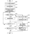
As described above, the extension amount of the
まず、最初のステップS100では、要求噴射量、噴射回数及び噴射時期の算出のために必要な、各種のセンサの検出結果を取得する。例えば、燃料噴射制御装置1は、アクセル開度センサ、回転センサ、コモンレール燃料圧センサ、水温センサ等から検出結果を取得する。そして、ステップS110において、取得した検出結果に基づき、要求噴射量を算出する。例えば、アクセル開度センサによって検出されるアクセルペダルの操作量(アクセル開度)と、回転センサの検出結果から得られるエンジン回転速度とに基づいて、アクセル開度に応じて要求されるエンジントルクを生成するための噴射量を要求噴射量として算出する。 First, in the first step S100, detection results of various sensors necessary for calculating the required injection amount, the number of injections, and the injection timing are acquired. For example, the fuel injection control device 1 acquires detection results from an accelerator opening sensor, a rotation sensor, a common rail fuel pressure sensor, a water temperature sensor, and the like. In step S110, the required injection amount is calculated based on the acquired detection result. For example, based on the accelerator pedal operation amount (accelerator opening) detected by the accelerator opening sensor and the engine speed obtained from the detection result of the rotation sensor, the engine torque required according to the accelerator opening is calculated. An injection amount for generation is calculated as a required injection amount.
ステップS120では、ステップS110にて算出した要求噴射量や、エンジン回転速度などに基つき、エンジンの各気筒の一燃焼サイクル中で、分割噴射を行うか否かを判定する。この際、分割噴射を行うと判定した場合には、さらに、ディーゼルエンジンの運転状態に基づき、分割噴射を行う回数、各噴射の噴射時期、及び各噴射における噴射量を算出する。一方、分割噴射を行わないと判定した場合には、1回の噴射の噴射時期を算出する。 In step S120, based on the required injection amount calculated in step S110, the engine rotation speed, and the like, it is determined whether or not to perform divided injection in one combustion cycle of each cylinder of the engine. At this time, when it is determined that the divided injection is performed, the number of times of performing the divided injection, the injection timing of each injection, and the injection amount in each injection are further calculated based on the operation state of the diesel engine. On the other hand, when it is determined that the divided injection is not performed, the injection timing of one injection is calculated.
ステップS130では、最も早く噴射時期が到来する噴射を対象として、その噴射の噴射量が、基準量以上であるか否かを判定する。ここで、基準量は、ピエゾインジェクタ24の噴射期間が最小噴射指令期間に定められたときに、ピエゾインジェクタ24から噴射される噴射量に対応する値に定めることができる。この判定処理において、噴射量が基準量以上であると判定されるとステップS140の処理に進み、基準量未満であると判定されるとステップS150の処理に進む。
In step S130, it is determined whether or not the injection amount of the injection is equal to or greater than the reference amount for the injection whose injection timing comes earliest. Here, the reference amount can be set to a value corresponding to the injection amount injected from the
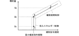
ステップS140では、噴射すべき噴射量は基準量以上であり、その噴射すべき噴射量の噴射のために最小噴射指令期間以上の噴射指令期間を設定することが可能であるので、従来と同様に、噴射期間により噴射量を制御する噴射期間制御を実行する。すなわち、本実施形態では、図5に示すように、噴射しようとする噴射量がQaであり、最小噴射指令期間に対応する噴射量Qb以上である場合には、噴射期間制御を実行し、噴射期間によって噴射量を制御する。 In step S140, the injection amount to be injected is equal to or greater than the reference amount, and an injection command period that is longer than the minimum injection command period can be set for injection of the injection amount to be injected. The injection period control for controlling the injection amount by the injection period is executed. That is, in the present embodiment, as shown in FIG. 5, when the injection amount to be injected is Qa and is equal to or greater than the injection amount Qb corresponding to the minimum injection command period, the injection period control is executed, and the injection is performed. The injection amount is controlled according to the period.
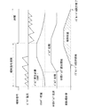
噴射すべき噴射量がQaである場合の噴射期間制御の一例が図8のタイミングチャートに示されている。この場合、コモンレール22における燃料圧力に応じて、要求噴射量Qaに対応する噴射指令期間が、マップ等により設定される。噴射指令期間がスタートすると、上述したように、充電スイッチ14のオン、オフが開始され、ピエゾ素子57に電気エネルギーが投入される。投入された電気エネルギーの総量が、バルブ開弁必要エネルギーに達すると、中間バルブ47が開弁を開始する。
An example of the injection period control when the injection amount to be injected is Qa is shown in the timing chart of FIG. In this case, the injection command period corresponding to the required injection amount Qa is set by a map or the like according to the fuel pressure in the common rail 22. When the injection command period starts, the charging switch 14 is turned on and off as described above, and electric energy is input to the
なお、図8において、噴射期間の初期に、充電のためのピエゾ電流のピーク値を、その後の充電のためのピエゾ電流のピーク値よりも低下させている理由は、中間バルブ47の急激な変位を防止して、騒音等の発生を抑制するためである。ただし、充電のためのピエゾ電流のピーク値は、噴射指令期間中、一定であっても良い。
In FIG. 8, the reason why the peak value of the piezo current for charging is lower than the peak value of the piezo current for subsequent charging in the early stage of the injection period is that the
ピエゾインジェクタ24のノズルニードル32は、中間バルブ47の開弁が開始されて、制御室38内の背圧が低下することにより、開弁し始める。このため、中間バルブ47の開弁開始とノズルニードル32の開弁開始とは時間的なずれがある。ノズルニードル32が開弁を開始することにより燃料の噴射が開始され、図8に示すように、ノズルニードル32が全開位置に達するまで燃料噴射率が徐々に増加していく。
The
そして、噴射指令期間が終了すると、放電スイッチ15のオン、オフが開始され、ピエゾ素子57に蓄積された電気エネルギーの放出が開始される。この電気エネルギーの放出により、ピエゾ素子57の電気エネルギーが減少すると、あるタイミングで中間バルブ47が閉弁位置へ向かって変位を開始する。そして、ピエゾ素子57の電気エネルギーがバルブ開弁必要エネルギーまで低下したときに、中間バルブ47は閉弁状態となる。
When the injection command period ends, the discharge switch 15 is turned on and off, and the electric energy accumulated in the
このような中間バルブ47の閉弁方向への変位に伴い、制御プレート40の上下面に印加される燃料圧に差圧が生じ、この差圧によって制御プレート40がノズルニードル32へ向かって変位し始める。それにより、ノズルニードル32のバルブ位置が閉弁位置に近づく。その結果、燃料噴射率は徐々に低下し、ノズルニードル32が閉弁位置に達したとき燃料噴射が停止される。
As the
噴射期間制御では、このようにして、燃料の噴射が開始されてから停止されるまでにピエゾインジェクタ24から噴射される燃料の総量が、噴射期間に応じたものとなるように制御される。
In the injection period control, the total amount of fuel injected from the
噴射すべき噴射量が、最小噴射指令期間に対応する噴射量Qbである場合の噴射期間制御の一例が図9のタイミングチャートに示されている。ピエゾ素子57に投入される電気エネルギーの総量は、ピエゾインジェクタ24に導入される燃料圧力が同じであれば、噴射量Qaの場合と同じであるが、噴射指令期間は、噴射量Qaの場合よりも短くなっている。ただし、最小噴射指令期間は、燃料噴射制御装置1における演算能力、演算周期、充電処理のための時間などによる制約を受ける。そのため、最小噴射指令期間の短縮化には自ずと限界がある。
An example of the injection period control when the injection amount to be injected is the injection amount Qb corresponding to the minimum injection command period is shown in the timing chart of FIG. The total amount of electrical energy input to the
ステップS150では、噴射すべき噴射量が基準量未満であり、噴射期間制御によっては、目標とする噴射量を精度良く噴射することができないため、ピエゾ素子57への投入エネルギー量によって噴射量を制御する投入エネルギー制御を実行する。この投入エネルギー制御では、図5に示すように、噴射指令期間は、最小噴射指令期間としつつ、ピエゾ素子57に投入する電気エネルギーの総量を、噴射量Qbを得るために必要な電気エネルギーの総量よりも小さく制御する。
In step S150, the injection amount to be injected is less than the reference amount, and the target injection amount cannot be accurately injected depending on the injection period control. Therefore, the injection amount is controlled by the amount of energy input to the
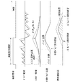
この投入エネルギー制御について、図6、図7、図10などを参照しつつ説明する。図6は、投入エネルギー制御の処理内容を示すフローチャートである。図7は、最小噴射指令期間に対応する噴射量Qb未満の噴射量とエネルギー総量との関係の一例を示すグラフである。図10は、最小噴射指令期間に対応する噴射量Qb未満の噴射量Qcを噴射させるための投入エネルギー制御の一例を示すタイミングチャートである。この図10のタイミングチャートには、最小噴射指令期間に対応する噴射量Qbを噴射する際の様子が点線で示されている。 This input energy control will be described with reference to FIG. 6, FIG. 7, FIG. FIG. 6 is a flowchart showing the processing contents of the input energy control. FIG. 7 is a graph showing an example of the relationship between the injection amount less than the injection amount Qb corresponding to the minimum injection command period and the total energy amount. FIG. 10 is a timing chart showing an example of input energy control for injecting an injection amount Qc less than the injection amount Qb corresponding to the minimum injection command period. In the timing chart of FIG. 10, the state when the injection amount Qb corresponding to the minimum injection command period is injected is indicated by a dotted line.
投入エネルギー制御では、まず、図6のフローチャートのステップS210において、噴射すべき噴射量に対応する電気エネルギーの総量を求める。例えば、図7に示すように、噴射すべき噴射量が、噴射量Qb未満の噴射量Qcである場合、図7に示す噴射量と電気エネルギーとの関係に従って、噴射量Qbに対応する電気エネルギーの総量Ebを基準とし、噴射量エネルギー感度β(Pc0,Qb、Qc)を減じることにより、噴射量Qcに対応する電気エネルギーの総量を求める。 In the input energy control, first, in step S210 of the flowchart of FIG. 6, the total amount of electrical energy corresponding to the injection amount to be injected is obtained. For example, as shown in FIG. 7, when the injection amount to be injected is an injection amount Qc that is less than the injection amount Qb, the electrical energy corresponding to the injection amount Qb according to the relationship between the injection amount and the electrical energy shown in FIG. The total amount of electrical energy corresponding to the injection amount Qc is obtained by subtracting the injection amount energy sensitivity β (Pc0, Qb, Qc) from the total amount Eb of
図7に示す噴射量と電気エネルギー総量との関係は、予め実験的に測定され、ECU19のROM等のメモリに保存される。ただし、噴射量と電気エネルギー総量との関係は、ピエゾインジェクタ24に導入される種々の燃料圧力において測定され、保存される。燃料圧力が変わると、中間バルブ47のバルブ開弁必要エネルギー等も変化し、その結果、噴射量と電気エネルギー総量との関係も変化するためである。なお、図7に示す噴射量と電気エネルギー総量との関係は、関数として保存しても良いし、マップとして保存しても良い。特に、関数として保存する場合には、噴射量と電気エネルギー総量との関係は、線形式で近似しても良い。
The relationship between the injection amount and the total electric energy shown in FIG. 7 is experimentally measured in advance and stored in a memory such as a ROM of the
上記のようにして、基準量未満の噴射量に対応する電気エネルギー総量を求めると、次に、図6のフローチャートのステップS220において、基準とする電気エネルギーの総量Ebに対する大きさに基づき、予め定められ記憶された関係に従って、充電スイッチ14をオンするオン期間を短縮した通電パターンを設定する。このオン期間を短縮するために用いる関係は、駆動回路10のコンデンサ13の充電電圧、充放電コイル16のインダクタンス、ピエゾ素子57の容量、抵抗18の抵抗値などから定められ、ECU19のROM等のメモリに保存される。
When the total amount of electric energy corresponding to the injection amount less than the reference amount is obtained as described above, next, in step S220 of the flowchart of FIG. 6, the predetermined amount is determined in advance based on the magnitude of the reference amount of electric energy Eb. In accordance with the stored relationship, an energization pattern in which the on period for turning on the charging switch 14 is shortened is set. The relationship used for shortening the ON period is determined from the charging voltage of the
例えば、噴射すべき噴射量をQcとする場合、図10のタイミングチャートに示すように、すべての充電スイッチ14のオン期間を、噴射量Qbのときの充電スイッチ14のオン期間よりも短縮しても良い。これにより、図10に示すように、ピエゾ素子57へのエネルギーの投入速度が低下され、ピエゾ素子57に投入する電気エネルギーの総量を、噴射量Qbに対応する電気エネルギーの総量Ebよりも、噴射量エネルギー感度β(Pc0,Qb、Qc)分だけ減少させることができる。その結果、図10に示すように、ノズルニードル32の開弁開始を遅くし、かつノズルニードル32の閉弁終了を早めることができ、噴射総量は、噴射量Qbよりも小さい噴射量Qcに制御される。
For example, when the injection amount to be injected is Qc, as shown in the timing chart of FIG. 10, the on period of all the charge switches 14 is shortened from the on period of the charge switch 14 at the injection amount Qb. Also good. As a result, as shown in FIG. 10, the energy input speed to the
なお、ピエゾ素子57に投入する電気エネルギーの総量を、基準とする電気エネルギーの総量Ebよりも小さくするために、すべての充電スイッチ14のオン期間を短縮するのではなく、少なくとも1回のオン期間を短縮するようにしても良い。あるいは、例えば、図10に点線で示す、ピエゾ電流の通電によるエネルギーの投入の少なくとも1つを省略し、すなわち、エネルギーの投入回数を少なくすることにより、ピエゾ素子57に投入する電気エネルギーの総量を減少させることもできる。
In order to make the total amount of electrical energy input to the
そして、ステップS230において、設定した通電パターンに従って、充電スイッチ14をオン、オフすることにより、ピエゾ素子57に投入する電気エネルギー総量を、目標とするエネルギー総量に制御する。
Then, in step S230, the total amount of electrical energy input to the
再び、図4のフローチャートに戻り説明を続ける。上述したステップS150にて投入エネルギー制御が実行されると、続くステップS160において、実際にピエゾインジェクタ24から噴射された燃料噴射量を算出し、保存しておく。この実際の燃料噴射量は、例えば、ピエゾインジェクタ24内に燃料圧力を測定する圧力センサを設け、当該圧力センサによって測定される、ノズルニードル32が開弁したときのピエゾインジェクタ24内の燃料圧力の低下度合から算出することができる。
Again, returning to the flowchart of FIG. When the input energy control is executed in step S150 described above, the fuel injection amount actually injected from the
ステップS170では、ステップS120で算出された回数の噴射が全て完了したか否かを判定する。すべての噴射が完了していないと判定した場合には、ステップS130の処理に戻る。一方、すべての噴射が完了したと判定した場合には、ステップS180の処理に進む。 In step S170, it is determined whether all the injections calculated in step S120 have been completed. If it is determined that all the injections are not completed, the process returns to step S130. On the other hand, if it is determined that all the injections have been completed, the process proceeds to step S180.
ステップS180では、検定要求が生じているか否かを判定する。検定要求とは、狙いとする噴射量に対応するよう、ピエゾ素子57に投入した電気エネルギー総量と、実際の噴射量とが対応しているかどうかを確認するための要求を意味する。この検定要求は、例えば、車両が走行を開始するときや、所定の時間が経過するごとに、燃料噴射制御装置1によって発生される。検定要求が生じていると判定した場合、ステップS190の処理に進み、生じていないと判定した場合、図4のフローチャートに示す処理を終了する。
In step S180, it is determined whether a verification request has occurred. The verification request means a request for confirming whether or not the total electric energy input to the
ステップS190では、ステップS120で算出された、各分割噴射の噴射量と、ステップS160にて算出され保存された実際の噴射量との噴射量差を比較する。この際、基準量未満の微小噴射が複数回行われた場合には、それら複数回の噴射における噴射量差の平均を求めても良い。 In step S190, the injection amount difference between each divided injection calculated in step S120 and the actual injection amount calculated and stored in step S160 is compared. At this time, when micro injection less than the reference amount is performed a plurality of times, an average of the injection amount differences in the plurality of injections may be obtained.
続くステップS200では、噴射量差が許容範囲を超えている場合には、図6に示す噴射量と電気エネルギー総量との関係を補正する。これにより、ピエゾインジェクタ24における各部の劣化や摩耗などにより、噴射量と電気エネルギーの総量との関係が変化しても、そのような変化によらず、ピエゾインジェクタ24から狙いとする噴射量を噴射させることができる。
In the subsequent step S200, when the injection amount difference exceeds the allowable range, the relationship between the injection amount and the total electric energy shown in FIG. 6 is corrected. Thus, even if the relationship between the injection amount and the total amount of electric energy changes due to deterioration or wear of each part in the
以上、本発明による好ましい実施形態について説明したが、本発明は、上述した実施形態になんら制限されることなく、本発明の主旨を逸脱しない範囲において、種々変形して実施することが可能である。 The preferred embodiments according to the present invention have been described above. However, the present invention is not limited to the above-described embodiments, and various modifications can be made without departing from the spirit of the present invention. .
例えば、上述した実施形態は、最小噴射指令期間に対応する噴射量Qbを基準量とし、噴射すべき噴射量が基準量以上であれば、噴射期間制御を実行し、基準量未満であれば、投入エネルギー制御を実行するものであった。 For example, in the above-described embodiment, the injection amount Qb corresponding to the minimum injection command period is set as a reference amount, and if the injection amount to be injected is equal to or larger than the reference amount, the injection period control is executed. The input energy control was executed.
しかしながら、最小噴射指令期間に対応する噴射量Qb以外の噴射量を基準量としても良い。例えば、図11に示すように、最小噴射指令期間よりも長い噴射指令期間に対応する噴射量Qaを基準量としても良い。この場合も、噴射すべき噴射量が、基準量以上であれば噴射期間制御を実行し、基準量未満であれば投入エネルギー制御を実行する。ただし、投入エネルギー制御においては、図11に示すように、噴射量Qaの噴射指令期間から最小噴射指令期間に向けて、噴射すべき噴射量が少なくなるほど、噴射指令期間も短くなるようにする。あるいは、噴射指令期間として、噴射量Qaの噴射指令期間と同じ噴射指令期間を使用しても良い。 However, an injection amount other than the injection amount Qb corresponding to the minimum injection command period may be used as the reference amount. For example, as shown in FIG. 11, an injection amount Qa corresponding to an injection command period longer than the minimum injection command period may be used as the reference amount. Also in this case, the injection period control is executed if the injection amount to be injected is equal to or greater than the reference amount, and the input energy control is executed if it is less than the reference amount. However, in the input energy control, as shown in FIG. 11, the injection command period is shortened as the injection amount to be injected decreases from the injection command period of the injection amount Qa to the minimum injection command period. Alternatively, the same injection command period as the injection command period for the injection amount Qa may be used as the injection command period.
また、上述した実施形態では、ピエゾインジェクタ24内に燃料圧力を測定する圧力センサを設け、この圧力センサによって測定される、ノズルニードル32が開弁したときのピエゾインジェクタ24内の燃料圧力の低下度合から、実際の燃料噴射量を算出することについて説明した。この構成に加えて、さらに、燃料の性状を検出する性状センサを設け、燃料の性状を加味して、燃料噴射量の算出を行っても良い。例えば、ディーゼルエンジンにおいては、寒冷地向けの燃料の性状は、寒冷地以外向けの燃料の性状とは異なる。これらの燃料は、燃料密度が異なるため、燃料の性状を検出して燃料噴射量の算出に反映させることにより、その算出精度を高めることができる。
In the above-described embodiment, a pressure sensor for measuring the fuel pressure is provided in the
1:燃料噴射制御装置、10:駆動回路、11:バッテリ、12:DC−DCコンバータ、12a:接続線、12b:接続線、13:コンデンサ、14:充電スイッチ、14a:フリーホイールダイオード、15:放電スイッチ、15a:フリーホイールダイオード、16:充放電コイル、18:抵抗、19:ECU、20:燃料タンク、21:燃料ポンプ、22:コモンレール、23:ディーゼルエンジン、24:ピエゾインジェクタ 1: fuel injection control device, 10: drive circuit, 11: battery, 12: DC-DC converter, 12a: connection line, 12b: connection line, 13: capacitor, 14: charge switch, 14a: freewheel diode, 15: Discharge switch, 15a: free wheel diode, 16: charge / discharge coil, 18: resistance, 19: ECU, 20: fuel tank, 21: fuel pump, 22: common rail, 23: diesel engine, 24: piezo injector
Claims (10)
前記エンジンの運転状態に基づいて、目標燃料噴射量を算出する噴射量算出部(S110、S120)と、
前記噴射量算出部が算出した前記目標燃料噴射量が、所定の基準燃料噴射量未満であると、前記基準燃料噴射量を噴射するときに前記ピエゾ素子に投入する基準総エネルギー量よりも小さい、前記目標燃料噴射量に対応する総エネルギー量を算出する総エネルギー量算出部(S210)と、
前記総エネルギー量算出部によって算出された総エネルギー量となるように、前記ピエゾ素子に投入するエネルギー量を制御する投入エネルギー量制御部(S220、S230)と、を備える燃料噴射制御装置。 When the piezo element (57) is extended by the input of energy, the nozzle valve (32) is opened, and when the piezo element (57) is contracted by the release of energy, the piezo injector (24) is closed. A fuel injection control device that controls the amount of fuel injected into the engine (23) using
An injection amount calculation unit (S110, S120) for calculating a target fuel injection amount based on the operating state of the engine;
When the target fuel injection amount calculated by the injection amount calculation unit is less than a predetermined reference fuel injection amount, the target fuel injection amount is smaller than a reference total energy amount that is input to the piezo element when the reference fuel injection amount is injected. A total energy amount calculation unit (S210) for calculating a total energy amount corresponding to the target fuel injection amount;
A fuel injection control device comprising: an input energy amount control unit (S220, S230) that controls an amount of energy input to the piezo element so as to be the total energy amount calculated by the total energy amount calculation unit.
高圧燃料が導入されて、前記ノズル弁の背圧を発生する背圧室(38)と、
前記背圧室と低圧通路との間に介設され、導入口を介して前記高圧燃料が導入される弁室(46)と、
前記弁室内に配設され、前記ピエゾ素子の伸長に応じて開弁方向に駆動されて、前記高圧燃料の導入口を閉塞するとともに、前記背圧室と前記低圧通路とを連通する弁体(47)と、を有し、
前記総エネルギー量算出部は、前記高圧燃料の圧力も考慮して、前記目標燃料噴射量に対応する総エネルギー量を算出する請求項1に記載の燃料噴射制御装置。 The piezo injector is
A back pressure chamber (38) in which high pressure fuel is introduced to generate back pressure of the nozzle valve;
A valve chamber (46) interposed between the back pressure chamber and the low pressure passage and into which the high pressure fuel is introduced via an inlet;
A valve body (not shown) disposed in the valve chamber and driven in the valve opening direction according to the extension of the piezo element to block the high-pressure fuel introduction port and communicate the back pressure chamber and the low-pressure passage ( 47) and
2. The fuel injection control device according to claim 1, wherein the total energy amount calculation unit calculates a total energy amount corresponding to the target fuel injection amount in consideration of the pressure of the high-pressure fuel.
前記目標燃料噴射量が前記基準燃料噴射量以上のときには、前記ピエゾインジェクタから噴射される燃料量は、前記噴射期間設定手段によって設定された噴射指令期間によって制御される請求項1乃至8のいずれかに記載の燃料噴射制御装置。 An injection period setting means (S140) for setting an injection command period according to the target fuel injection amount when the target fuel injection amount calculated by the injection amount calculation unit is equal to or greater than the reference fuel injection amount;
The fuel amount injected from the piezo injector when the target fuel injection amount is equal to or greater than the reference fuel injection amount is controlled by an injection command period set by the injection period setting means. A fuel injection control device according to claim 1.
前記実噴射量推定部によって推定された実際の燃料噴射量と前記目標燃料噴射量とが相違する場合、前記総エネルギー量算出部は、前記相違に応じて補正した総エネルギー量を算出する請求項1乃至9のいずれかに記載の燃料噴射制御装置。 An actual injection amount estimation unit (S160) for estimating an actual fuel injection amount injected from the piezo injector;
The total energy amount calculation unit calculates a corrected total energy amount according to the difference when the actual fuel injection amount estimated by the actual injection amount estimation unit and the target fuel injection amount are different. The fuel injection control device according to any one of 1 to 9.
Priority Applications (2)
| Application Number | Priority Date | Filing Date | Title |
|---|---|---|---|
| JP2017051477A JP6772913B2 (en) | 2017-03-16 | 2017-03-16 | Fuel injection control device |
| DE102018104419.4A DE102018104419A1 (en) | 2017-03-16 | 2018-02-27 | Fuel injection control |
Applications Claiming Priority (1)
| Application Number | Priority Date | Filing Date | Title |
|---|---|---|---|
| JP2017051477A JP6772913B2 (en) | 2017-03-16 | 2017-03-16 | Fuel injection control device |
Publications (2)
| Publication Number | Publication Date |
|---|---|
| JP2018155146A true JP2018155146A (en) | 2018-10-04 |
| JP6772913B2 JP6772913B2 (en) | 2020-10-21 |
Family
ID=63372099
Family Applications (1)
| Application Number | Title | Priority Date | Filing Date |
|---|---|---|---|
| JP2017051477A Expired - Fee Related JP6772913B2 (en) | 2017-03-16 | 2017-03-16 | Fuel injection control device |
Country Status (2)
| Country | Link |
|---|---|
| JP (1) | JP6772913B2 (en) |
| DE (1) | DE102018104419A1 (en) |
Cited By (1)
| Publication number | Priority date | Publication date | Assignee | Title |
|---|---|---|---|---|
| WO2021065426A1 (en) * | 2019-10-04 | 2021-04-08 | 株式会社豊田自動織機 | Internal combustion engine |
Citations (3)
| Publication number | Priority date | Publication date | Assignee | Title |
|---|---|---|---|---|
| JP2004076646A (en) * | 2002-08-19 | 2004-03-11 | Denso Corp | Fuel injection control device |
| JP2016008521A (en) * | 2014-06-23 | 2016-01-18 | 株式会社豊田自動織機 | Internal combustion engine |
| JP2016084748A (en) * | 2014-10-27 | 2016-05-19 | 株式会社日本自動車部品総合研究所 | Fuel injection device |
-
2017
- 2017-03-16 JP JP2017051477A patent/JP6772913B2/en not_active Expired - Fee Related
-
2018
- 2018-02-27 DE DE102018104419.4A patent/DE102018104419A1/en not_active Ceased
Patent Citations (3)
| Publication number | Priority date | Publication date | Assignee | Title |
|---|---|---|---|---|
| JP2004076646A (en) * | 2002-08-19 | 2004-03-11 | Denso Corp | Fuel injection control device |
| JP2016008521A (en) * | 2014-06-23 | 2016-01-18 | 株式会社豊田自動織機 | Internal combustion engine |
| JP2016084748A (en) * | 2014-10-27 | 2016-05-19 | 株式会社日本自動車部品総合研究所 | Fuel injection device |
Cited By (3)
| Publication number | Priority date | Publication date | Assignee | Title |
|---|---|---|---|---|
| WO2021065426A1 (en) * | 2019-10-04 | 2021-04-08 | 株式会社豊田自動織機 | Internal combustion engine |
| JP2021059999A (en) * | 2019-10-04 | 2021-04-15 | 株式会社豊田自動織機 | Internal combustion engine |
| CN114502826A (en) * | 2019-10-04 | 2022-05-13 | 株式会社丰田自动织机 | Internal combustion engine |
Also Published As
| Publication number | Publication date |
|---|---|
| JP6772913B2 (en) | 2020-10-21 |
| DE102018104419A1 (en) | 2018-09-20 |
Similar Documents
| Publication | Publication Date | Title |
|---|---|---|
| JP4582064B2 (en) | Fuel injection control device | |
| JP4535032B2 (en) | Fuel injection control device | |
| US9200580B2 (en) | Method and device for operating an injection valve | |
| JP6121552B2 (en) | Fuel injection control device for internal combustion engine | |
| US20060082252A1 (en) | Method for determining the position of a movable shut-off element of an injection valve | |
| JP4911197B2 (en) | Control device for direct acting fuel injection valve | |
| US9086028B2 (en) | Method and device for operating an injection valve | |
| US9945317B2 (en) | Fuel injection device | |
| JP2006125371A (en) | Accumulator fuel injection device | |
| US7055494B2 (en) | Low heat generation fuel injection system | |
| KR102086327B1 (en) | Control device for fuel pump and control method thereof | |
| JP4476950B2 (en) | Fuel injection control device | |
| JP5482717B2 (en) | Fuel injection control device for internal combustion engine | |
| JP4144375B2 (en) | Accumulated fuel injection system | |
| JP4743138B2 (en) | Fuel injection device | |
| JP6772913B2 (en) | Fuel injection control device | |
| JP4604356B2 (en) | Piezo actuator driving circuit and fuel injection device | |
| US11131264B2 (en) | Fuel injection control device | |
| JP3758312B2 (en) | Engine fuel injector | |
| JP4483822B2 (en) | Fuel injection control device | |
| JP4803016B2 (en) | Fuel injection control device | |
| JP2003239821A (en) | Fuel injection controller | |
| JP2002285892A (en) | Fuel injection control device for internal combustion engine | |
| JP4591436B2 (en) | Fuel injection device | |
| JP5532885B2 (en) | Fuel injection device |
Legal Events
| Date | Code | Title | Description |
|---|---|---|---|
| A621 | Written request for application examination |
Free format text: JAPANESE INTERMEDIATE CODE: A621 Effective date: 20190424 |
|
| A131 | Notification of reasons for refusal |
Free format text: JAPANESE INTERMEDIATE CODE: A131 Effective date: 20200225 |
|
| A977 | Report on retrieval |
Free format text: JAPANESE INTERMEDIATE CODE: A971007 Effective date: 20200220 |
|
| TRDD | Decision of grant or rejection written | ||
| A01 | Written decision to grant a patent or to grant a registration (utility model) |
Free format text: JAPANESE INTERMEDIATE CODE: A01 Effective date: 20200901 |
|
| A61 | First payment of annual fees (during grant procedure) |
Free format text: JAPANESE INTERMEDIATE CODE: A61 Effective date: 20200914 |
|
| R151 | Written notification of patent or utility model registration |
Ref document number: 6772913 Country of ref document: JP Free format text: JAPANESE INTERMEDIATE CODE: R151 |
|
| LAPS | Cancellation because of no payment of annual fees |