JP2018141867A - Image forming apparatus - Google Patents
Image forming apparatus Download PDFInfo
- Publication number
- JP2018141867A JP2018141867A JP2017035778A JP2017035778A JP2018141867A JP 2018141867 A JP2018141867 A JP 2018141867A JP 2017035778 A JP2017035778 A JP 2017035778A JP 2017035778 A JP2017035778 A JP 2017035778A JP 2018141867 A JP2018141867 A JP 2018141867A
- Authority
- JP
- Japan
- Prior art keywords
- speed
- loop
- sheet
- fixing
- band
- Prior art date
- Legal status (The legal status is an assumption and is not a legal conclusion. Google has not performed a legal analysis and makes no representation as to the accuracy of the status listed.)
- Pending
Links
Images


Classifications
-
- G—PHYSICS
- G03—PHOTOGRAPHY; CINEMATOGRAPHY; ANALOGOUS TECHNIQUES USING WAVES OTHER THAN OPTICAL WAVES; ELECTROGRAPHY; HOLOGRAPHY
- G03G—ELECTROGRAPHY; ELECTROPHOTOGRAPHY; MAGNETOGRAPHY
- G03G15/00—Apparatus for electrographic processes using a charge pattern
- G03G15/65—Apparatus which relate to the handling of copy material
- G03G15/6555—Handling of sheet copy material taking place in a specific part of the copy material feeding path
- G03G15/657—Feeding path after the transfer point and up to the fixing point, e.g. guides and feeding means for handling copy material carrying an unfused toner image
-
- G—PHYSICS
- G03—PHOTOGRAPHY; CINEMATOGRAPHY; ANALOGOUS TECHNIQUES USING WAVES OTHER THAN OPTICAL WAVES; ELECTROGRAPHY; HOLOGRAPHY
- G03G—ELECTROGRAPHY; ELECTROPHOTOGRAPHY; MAGNETOGRAPHY
- G03G15/00—Apparatus for electrographic processes using a charge pattern
- G03G15/50—Machine control of apparatus for electrographic processes using a charge pattern, e.g. regulating differents parts of the machine, multimode copiers, microprocessor control
- G03G15/5029—Machine control of apparatus for electrographic processes using a charge pattern, e.g. regulating differents parts of the machine, multimode copiers, microprocessor control by measuring the copy material characteristics, e.g. weight, thickness
-
- G—PHYSICS
- G03—PHOTOGRAPHY; CINEMATOGRAPHY; ANALOGOUS TECHNIQUES USING WAVES OTHER THAN OPTICAL WAVES; ELECTROGRAPHY; HOLOGRAPHY
- G03G—ELECTROGRAPHY; ELECTROPHOTOGRAPHY; MAGNETOGRAPHY
- G03G2215/00—Apparatus for electrophotographic processes
- G03G2215/00362—Apparatus for electrophotographic processes relating to the copy medium handling
- G03G2215/00367—The feeding path segment where particular handling of the copy medium occurs, segments being adjacent and non-overlapping. Each segment is identified by the most downstream point in the segment, so that for instance the segment labelled "Fixing device" is referring to the path between the "Transfer device" and the "Fixing device"
- G03G2215/00413—Fixing device
-
- G—PHYSICS
- G03—PHOTOGRAPHY; CINEMATOGRAPHY; ANALOGOUS TECHNIQUES USING WAVES OTHER THAN OPTICAL WAVES; ELECTROGRAPHY; HOLOGRAPHY
- G03G—ELECTROGRAPHY; ELECTROPHOTOGRAPHY; MAGNETOGRAPHY
- G03G2215/00—Apparatus for electrophotographic processes
- G03G2215/00362—Apparatus for electrophotographic processes relating to the copy medium handling
- G03G2215/00535—Stable handling of copy medium
- G03G2215/00679—Conveying means details, e.g. roller
-
- G—PHYSICS
- G03—PHOTOGRAPHY; CINEMATOGRAPHY; ANALOGOUS TECHNIQUES USING WAVES OTHER THAN OPTICAL WAVES; ELECTROGRAPHY; HOLOGRAPHY
- G03G—ELECTROGRAPHY; ELECTROPHOTOGRAPHY; MAGNETOGRAPHY
- G03G2215/00—Apparatus for electrophotographic processes
- G03G2215/00362—Apparatus for electrophotographic processes relating to the copy medium handling
- G03G2215/00535—Stable handling of copy medium
- G03G2215/00717—Detection of physical properties
- G03G2215/00721—Detection of physical properties of sheet position
-
- G—PHYSICS
- G03—PHOTOGRAPHY; CINEMATOGRAPHY; ANALOGOUS TECHNIQUES USING WAVES OTHER THAN OPTICAL WAVES; ELECTROGRAPHY; HOLOGRAPHY
- G03G—ELECTROGRAPHY; ELECTROPHOTOGRAPHY; MAGNETOGRAPHY
- G03G2215/00—Apparatus for electrophotographic processes
- G03G2215/00362—Apparatus for electrophotographic processes relating to the copy medium handling
- G03G2215/00919—Special copy medium handling apparatus
- G03G2215/00945—Copy material feeding speed varied over the feed path
Landscapes
- Physics & Mathematics (AREA)
- General Physics & Mathematics (AREA)
- Engineering & Computer Science (AREA)
- Microelectronics & Electronic Packaging (AREA)
- Fixing For Electrophotography (AREA)
- Control Or Security For Electrophotography (AREA)
Abstract
Description
本発明は、画像を形成してシートに記録する画像形成部を有する、複写機、ファクシミリ、多機能プリンタ等の画像形成装置に関する。 The present invention relates to an image forming apparatus such as a copier, a facsimile machine, or a multi-function printer having an image forming unit that forms an image and records it on a sheet.
電子写真方式を用いた画像形成装置においては、像担持体上のトナー像が像担持体と転写ローラとのニップ部(転写ニップ部)にてシートに転写された後、このシートが搬送ガイドを経て定着部の定着部材と加圧ローラとのニップ部(定着ニップ部)に導かれる。ここで、シートの先端が定着ニップ部に突入した状態では、その後端部がまだ転写ニップ部を通過していない状態の場合がある。一方、定着部に具備される加圧ローラの熱膨張や固体差、使用環境あるいは経年変化によって定着ニップ部におけるシート搬送速度(定着搬送速度)と、転写ニップ部におけるシート搬送速度(転写搬送速度)との間に差が生じる場合がある。このような場合、定着搬送速度が転写搬送速度を上回ると、未定着トナー像を担持しているシートが定着ニップ部と転写ニップ部間で定着部側に引っ張られるという現象が発生し、画像劣化を招くおそれがある。したがって、転写部と定着部との間を搬送されるシートにたるみとしてのループを形成するようにすれば、その間でシートが引っ張られるという現象の発生を未然に防ぐことが可能となる。 In an image forming apparatus using an electrophotographic system, a toner image on an image carrier is transferred to a sheet at a nip portion (transfer nip portion) between the image carrier and a transfer roller. Then, it is guided to the nip portion (fixing nip portion) between the fixing member of the fixing portion and the pressure roller. Here, when the leading edge of the sheet enters the fixing nip portion, the trailing edge portion may not yet pass through the transfer nip portion. On the other hand, the sheet conveyance speed (fixing conveyance speed) in the fixing nip part and the sheet conveyance speed (transfer conveyance speed) in the transfer nip part due to thermal expansion and solid difference of the pressure roller provided in the fixing part, usage environment or aging change. There may be a difference between In such a case, if the fixing conveyance speed exceeds the transfer conveyance speed, a phenomenon in which a sheet carrying an unfixed toner image is pulled to the fixing unit side between the fixing nip portion and the transfer nip portion, and image deterioration occurs. May be incurred. Therefore, if a loop as a slack is formed in the sheet conveyed between the transfer unit and the fixing unit, it is possible to prevent the phenomenon that the sheet is pulled between them.
しかし、定着搬送速度が転写搬送速度を下まわり過ぎると、シートに必要以上のループが形成されることになる。このため、シートが搬送ガイドに接触して未定着トナー像を削り取られたり、転写部における画像転写後のシートの分離方向(姿勢)や、定着部への定着前のシートの入射角(姿勢)等が不安定となって、転写分離時の画像飛び散り、定着部でのオフセット等が発生したりする。 However, if the fixing conveyance speed is too lower than the transfer conveyance speed, loops more than necessary are formed on the sheet. For this reason, the sheet comes into contact with the conveyance guide and the unfixed toner image is scraped off, the separation direction (posture) of the sheet after image transfer in the transfer unit, and the incident angle (posture) of the sheet before fixing to the fixing unit Or the like becomes unstable, causing image scattering during transfer separation, offset in the fixing unit, or the like.
したがって、転写部と定着部との間では、シートは適度なループを形成して搬送されることが望ましく、このとき転写搬送速度と定着搬送速度とに関しては、ほぼ等速か若干定着搬送速度を転写搬送速度より遅くすることが必要となる。 Therefore, it is desirable that the sheet is conveyed in a suitable loop between the transfer unit and the fixing unit. At this time, the transfer conveyance speed and the fixing conveyance speed are approximately equal or slightly fixed. It is necessary to make it slower than the transfer conveyance speed.
よって、転写部と定着部との間でシートに適度なループを形成してシートが引っ張られる、あるいは弛み過ぎるという現象の発生を防止し、画像劣化を解決する手段が提案されている。 Therefore, there has been proposed means for solving the image deterioration by preventing an occurrence of a phenomenon in which an appropriate loop is formed on the sheet between the transfer unit and the fixing unit and the sheet is pulled or loosened too much.
例えば、定着部と転写部との間の搬送ガイドにシートのループを検出するループ検出センサを設ける。このセンサの検出結果に基づいて、シートのループ量が所定量以下の場合には、転写搬送速度よりも遅い第1の定着搬送速度で制御する。また、ループ量が所定量以上と検出した場合には転写搬送速度よりも速い第2の定着搬送速度で制御する画像形成装置が提案されている(特許文献1)。 For example, a loop detection sensor that detects a loop of the sheet is provided in the conveyance guide between the fixing unit and the transfer unit. Based on the detection result of the sensor, when the sheet loop amount is equal to or less than a predetermined amount, the control is performed at the first fixing conveyance speed slower than the transfer conveyance speed. Further, an image forming apparatus has been proposed that performs control at a second fixing conveyance speed that is faster than the transfer conveyance speed when the loop amount is detected to be a predetermined amount or more (Patent Document 1).
また、前記第1の搬送速度と、第2の搬送速度との組合せを複数設ける。そして、ループ検出部によって転写部でトナー像が転写されたシートの先端が定着ニップ部に到達したときのループ量を検出し、そのループ量が解消されるまでの時間から前記複数の組合せの中から最適な速度と速度制御幅を選択し、制御する画像形成装置が提案されている(特許文献2)。 A plurality of combinations of the first transport speed and the second transport speed are provided. Then, the loop amount is detected when the leading edge of the sheet on which the toner image is transferred by the transfer unit by the loop detection unit reaches the fixing nip portion, and the time until the loop amount is eliminated is determined from among the plurality of combinations. An image forming apparatus that selects and controls the optimum speed and speed control width from the above has been proposed (Patent Document 2).
定着部によるシート搬送は、加熱による膨張等によるローラの外径公差、表面性ばらつき、耐久変化等全てがシート搬送速度に影響を及ぼす。このため、定着搬送速度を決定する場合には転写部と定着部の両方について前記項目を考慮する必要がある。この場合、転写部にベルトを含む場合はベルトの内周長やベルトを搬送するローラについて考慮する必要が生じてくる。 In the sheet conveyance by the fixing unit, the outer diameter tolerance of the roller, the surface property variation, the durability change, and the like due to the expansion due to the heating all affect the sheet conveyance speed. Therefore, when determining the fixing conveyance speed, it is necessary to consider the above items for both the transfer unit and the fixing unit. In this case, when a belt is included in the transfer portion, it is necessary to consider the inner peripheral length of the belt and the roller that conveys the belt.
上記従来技術の構成にあっても、転写搬送速度よりも遅い定着搬送速度を設定する場合、上記様々なばらつき要因を含んだ上で設定しなければならず、個々の画像形成装置に対しては必要以上に遅くなる場合が多々生じてくる。これは転写搬送速度よりも速い定着搬送速度を設定する場合も同様である。 Even in the configuration of the above prior art, when setting a fixing conveyance speed slower than the transfer conveyance speed, it is necessary to set it including the above various variation factors. There are many cases where it is slower than necessary. The same applies to the case where a fixing conveyance speed faster than the transfer conveyance speed is set.
このため、定着部による第1と第2のシート搬送速度間の速度幅は本来の個々の画像形成装置に必要な第1と第2のシート搬送速度間の速度幅を超えてしまうことがある。このように定着部における第1と第2のシート搬送速度の速度幅が大きい場合には、速度切り換え時に速度変化が大きくなり、シート上の未定着トナーを定着ニップ部で永久固着させる際に、画像が飛び散り気味になる場合や画像が伸びてしまう等、画像不良を生ずる場合がある。 For this reason, the speed width between the first and second sheet transport speeds by the fixing unit may exceed the speed width between the first and second sheet transport speeds necessary for the original individual image forming apparatus. . Thus, when the speed width of the first and second sheet conveying speeds in the fixing unit is large, the speed change becomes large when the speed is switched, and when the unfixed toner on the sheet is permanently fixed in the fixing nip part, An image defect may occur, for example, when the image is scattered and the image is stretched.
また、第1と第2のシート搬送速度の組合せを複数設けた場合でも、速度帯を細かく設定しないと速度が急変することにより上記と同様の問題が生ずる。 Even when a plurality of combinations of the first and second sheet conveying speeds are provided, the same problem as described above occurs due to a rapid change in speed unless the speed band is set finely.
そこで本発明の目的は、転写部と定着部との間ではシートに適切なループを形成しつつ、画像問題が発生しない画像形成装置を提供するものである。 SUMMARY OF THE INVENTION Accordingly, an object of the present invention is to provide an image forming apparatus in which an image problem does not occur while an appropriate loop is formed on a sheet between a transfer portion and a fixing portion.
上記目的を達成するための本発明に係る代表的な構成は、像担持体に形成されたトナー像を、シートを転写搬送速度で搬送しつつ転写する転写部と、シートに転写されたトナー像を、シートを定着搬送速度で搬送しつつ定着させる定着部と、前記転写部と前記定着部の間に生ずるシートのループ状態を検出するループ検出部と、前記ループ検出部により検出したループ状態に応じ、前記定着搬送速度を第1速度と前記第1速度より遅い第2速度に切り換えてループ量を制御する制御部と、を有し、前記制御部は、前記転写搬送速度よりも遅いシート搬送速度と、前記転写搬送速度よりも速いシート搬送速度の間で、前記第1速度と前記第2速度の組合せである速度帯を複数有し、搬送されるシートのループ状態の変化に応じて前記速度帯を切り換えて前記定着搬送速度を制御することを特徴とする。 In order to achieve the above object, a typical configuration according to the present invention includes a transfer unit that transfers a toner image formed on an image carrier while conveying the sheet at a transfer conveyance speed, and a toner image transferred to the sheet. A fixing unit that fixes the sheet while conveying the sheet at a fixing conveyance speed, a loop detection unit that detects a loop state of the sheet generated between the transfer unit and the fixing unit, and a loop state detected by the loop detection unit. And a controller that controls a loop amount by switching the fixing conveyance speed between a first speed and a second speed that is slower than the first speed, and the control section conveys a sheet that is slower than the transfer conveyance speed. A plurality of speed bands, which are combinations of the first speed and the second speed, between the speed and the sheet transport speed faster than the transfer transport speed, and according to a change in a loop state of the transported sheet Turn off speed band Recombinant and wherein the controller controls the fixing conveying speed.
本発明によれば、転写部と定着部間でシートに適切なループを形成しつつ、画像飛び散りや画像伸びなどを抑制することができる。 According to the present invention, it is possible to suppress image scattering and image expansion while forming an appropriate loop on the sheet between the transfer portion and the fixing portion.
<画像形成装置の全体構成>
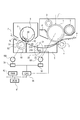
図1は本実施形態にかかる画像形成装置の主に転写部および定着部の部分を示す概略構成図である。本実施形態の画像形成装置は転写式電子写真プロセスによって画像形成を行う複写機もしくはプリンタである。
<Overall configuration of image forming apparatus>
FIG. 1 is a schematic configuration diagram mainly showing a transfer unit and a fixing unit of the image forming apparatus according to the present embodiment. The image forming apparatus according to the present embodiment is a copying machine or a printer that forms an image by a transfer type electrophotographic process.
まず、画像形成装置の全体構成を概略説明する。1は図1の時計回り方向に所定のプロセススピード(周速度)をもって回転駆動される像担持体としてのドラム型の電子写真感光体(感光ドラム)である。M1はこの感光ドラム1等を駆動する画像形成装置本体のメインモータである。
First, the overall configuration of the image forming apparatus will be outlined.
32は前記メインモータM1のコントローラであり、CPU30によって制御される。CPU30は、ROM61内に格納された制御手順に従って本画像形成装置の各構成を制御する。62はCPU30の作業領域を提供するRAMである。
この感光ドラム1は、その回転過程で帯電ローラ2により所定の極性・電位に一様に一次帯電処理される。その帯電処理面に対して不図示の露光装置により光像露光Lがなされて目的の画像情報の静電潜像が形成される。
The
次いでその潜像が現像部3によってトナー像として可視化され、感光ドラム1と転写部を構成する転写ローラ4との圧接ニップ部である転写ニップ部Tに至る。前記トナー像の形成と同期して図示しないシート給送部からシートPが転写ニップ部Tに搬送され、転写ニップ部Tで感光ドラム1及び転写ローラ4の回転によるシート搬送速度(転写搬送速度)で搬送されながら、転写ローラ4へのバイアス印加によって前記トナー像がシートPに順次転写されていく。
Then, the latent image is visualized as a toner image by the developing
転写ローラ4は感光ドラム1とギヤを介して接続されており、同様にメインモータM1を駆動源として回転駆動される。
The
トナー像の転写を受けたシートPは感光ドラム1面から分離されて搬送ガイド5上を搬送されて定着部7へと向かう。シートP上のトナー像は定着部7において加熱定着処理を受け、画像形成物(コピー、プリント)として出力されていく。
The sheet P that has received the transfer of the toner image is separated from the surface of the
シートPへのトナー像転写後の感光ドラム1面はクリーニング部6にて転写残りトナー等の残存付着物の除去処理を受け、繰り返して作像に供される。
The surface of the
<定着部>
本実施形態の定着部7は加圧部材駆動式・テンションレスタイプのフィルム加熱方式の加熱装置である。8は耐熱性樹脂製の横長ステイであり、エンドレス耐熱性フィルム(定着フィルム)9の内面ガイド部材となる。
<Fixing part>
The
エンドレスの耐熱性フィルム9は、加熱体としてのヒータ40を含む上記ステイ8に外嵌させてある。
The endless heat
加圧ローラ50はヒータ40との間でフィルム9を挟んで圧接ニップである定着ニップ部Nを形成し、フィルム9を駆動する回転体としての加圧ローラである。この加圧ローラ50は、アルミニウム・鉄・ステンレス等の芯金51と、この軸に外装したシリコンゴム等の離型性のよい耐熱ゴム弾性体52からなる。また、表面にはシートP、定着フィルム9の搬送性、トナーの汚れ防止の理由からフッ素樹脂を分散させたコート層(不図示)設けてある。
The
芯金51の端部が定着モータM2により駆動されることで図1の反時計方向に回転駆動され、その駆動力によりエンドレスの耐熱性フィルム9の内面がヒータ40に密着摺動しながら時計方向に回転駆動される。
The end of the cored
更に詳述すると、加圧ローラ50が回転駆動すると定着ニップ部Nにおいてフィルム9に回転加圧ローラ50との摩擦力で移動力がかかる。このため、フィルム9が加圧ローラ50の回転周速と略同速度をもってフィルム内面がヒータ40面を摺動しつつ時計方向に回転駆動される。そして、転写部でトナー像が転写されたシートは加圧ローラ50の回転による定着搬送速度で搬送されながら、加熱加圧されてトナー像がシートに定着される。
More specifically, when the
なお、メインモータM1、定着モータM2の各モータは、それぞれ対応するコントローラ32,33を介してCPU30により駆動制御される。ここで、シートの搬送速度がプロセススピードとなるように、上記したメインモータM1及び、定着モータM2をそれぞれ制御する。
The motors of the main motor M1 and the fixing motor M2 are driven and controlled by the
またCPU30は、転写ニップ部Tと定着ニップ部NでのシートPのループ量を所定範囲内に保持するために、定着ニップ部Nでのシート搬送速度(定着搬送速度)Vfを定着モータM2の回転速度を切り換えることにより制御する。
Further, the
<ループ検出部>
前記転写部と定着部のシート搬送経路には、シートPのループ量を検出フラグ21によって検出するするループ検出部が設けられている。検出フラグ21は、転写部と定着部の間に設けられた搬送ガイド5面上に、揺動軸21Aを中心に揺動可能な棒状部材で構成され、この検出フラグ21の端部が搬送ガイド5の搬送面に突出するように配置されている。検出フラグ21はバネ部材(不図示)により付勢され、検出フラグ21の端部に上から接触するシートPに押されて、当該シートPによって形成されたループ量に応じて揺動する。この検出フラグ21には、搬送面の下方に向けて伸びる遮光フラグ21Bが設けられている。この遮光フラグ21Bは、検出フラグ21の動きに連動して、シートPのループ量が所定値を超えたか否かを検出するためのフォトインタラプタ22の光路を遮断/開放する。すなわち、フォトインタラプタ22は、検出フラグ21の揺動運動に応じてオン/オフする。このフォトインタラプタ22と検出フラグ21は、互い協動してループ検出部となるループ検出センサ20を構成する。
<Loop detection unit>
A loop detection unit that detects the loop amount of the sheet P by a
なお、ループ検出センサ20が検出するループ量とは、転写ニップ部Tと定着ニップ部Nの2点間の距離と、その2点間を実際にシートPがループを持って結んだ距離との差分である。すなわち、定着ニップ部Nにおけるシート搬送速度(定着搬送速度)Vfを、転写ニップ部Tにおけるシート搬送速度(転写搬送速度)Vtと同じ速度とした場合における、シート上の2点間の距離と、シートPがループを持つよう定着搬送速度Vfを制御した場合における、シート上の2点間の距離との差分である。したがって、定着搬送速度Vfを転写搬送速度Vtより遅くするとループ量が増加し、定着搬送速度Vfを転写搬送速度Vtより速くするとループ量が減少する。
The loop amount detected by the
ここで、ループ検出センサ20の出力はCPU30に取り込まれ、そこでCPU30に処理された情報を基に制御を行なうことができる。
Here, the output of the
<ループ制御>
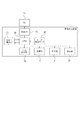
ここで、シートのループ制御について説明する。図2はループ制御するための制御部の構成ブロック図であり、この制御部によって定着搬送速度を切り換え、ループ量を制御する。
<Loop control>
Here, sheet loop control will be described. FIG. 2 is a block diagram showing the configuration of a control unit for loop control. The control unit switches the fixing conveyance speed and controls the loop amount.
(制御部)
図2の構成を説明すると、PC71からプリントの指示がなされると、USBケーブル等の伝達部(不図示)によって画像形成装置のI/F部72、すなわちUSBポート等から信号を受信する。もしくは指示/表示部73から信号を受信する場合もある。画像形成装置が信号を受信した場合、CPU30が画像形成に必要なシート給送部74、定着部7、転写部4、排出部77の動作を行う。その際ループ検出センサ20によって定着部75の動作を変化させることで画像品質の良いプリントが完成する。
(Control part)
Referring to the configuration of FIG. 2, when a print instruction is issued from the
本実施形態のように転写搬送速度と定着搬送速度の相互関係を判断して定着搬送速度の切換制御を行うことで、画像形成装置の設計寸法ばらつき、各ローラの表面性ばらつきを全て含んだシート搬送速度設定をする必要が無くなり、実際に使用している画像形成装置において最適なシート搬送速度で制御することが可能となる。 As in this embodiment, by determining the mutual relationship between the transfer conveyance speed and the fixing conveyance speed and performing switching control of the fixing conveyance speed, the sheet includes all of the design size variation of the image forming apparatus and the surface property variation of each roller. It is not necessary to set the conveyance speed, and it is possible to control at an optimum sheet conveyance speed in the image forming apparatus actually used.
(通常ループ制御)
次にループ制御動作について、まず通常のループ制御について説明し、次に本実施形態の特徴である補正ループ制御について説明する。
(Normal loop control)
Next, with regard to the loop control operation, normal loop control will be described first, and then correction loop control, which is a feature of the present embodiment, will be described.
通常のループ制御について、画像形成動作開始から、通常ループ制御を経て画像形成動作終了までの流れを図3及び図4を用いて説明する。 Regarding normal loop control, the flow from the start of the image forming operation to the end of the image forming operation through the normal loop control will be described with reference to FIGS.
画像形成装置が電源ONされた後、画像形成開始の信号が入力されると(S1)、前述したように未定着トナーが転写されたシートPが定着ニップ部Nへ向けて搬送される。 When a signal for starting image formation is input after the image forming apparatus is turned on (S1), the sheet P on which the unfixed toner has been transferred is conveyed toward the fixing nip N as described above.
シートPの先端が定着部7の定着ニップ部Nに突入すると(S2)、図4に示すように、定着モータM2の回転速度をR1に切り換え(S3)、定着搬送速度VfをCPU30によって転写搬送速度Vtより遅い速度Vbに設定する。次いでステップS4に進んで、ループ検出センサ20出力がONかOFFかを判断する。このループ検出センサ20はループが所定量より大きいときはONし、ループが所定量より小さくなるとOFFする。
When the leading edge of the sheet P enters the fixing nip N of the fixing unit 7 (S2), as shown in FIG. 4, the rotation speed of the fixing motor M2 is switched to R1 (S3), and the fixing conveyance speed Vf is transferred and conveyed by the
ここで、定着モータM2の回転速度R1は、定着搬送速度Vfが、転写搬送速度Vtより遅くなる回転速度である。速度VbはシートPの種類、連続通紙枚数、定着温度制御状況に応じた各部品の熱膨張、加圧力のばらつき、ローラ径の公差等の条件を考慮して、どのような状況においても必ずVt>Vbとなるように設定することが必要である。 Here, the rotation speed R1 of the fixing motor M2 is a rotation speed at which the fixing conveyance speed Vf is slower than the transfer conveyance speed Vt. The speed Vb is always taken into consideration in any situation in consideration of conditions such as thermal expansion of parts, variation in pressure, tolerance of roller diameter, etc. according to the type of sheet P, the number of continuous sheets to be passed, and the fixing temperature control status. It is necessary to set so that Vt> Vb.
また、シートPの先端が定着ニップ部Nに突入するタイミングは、CPU30により画像形成開始のタイミングから算定される。そして、シートPの先端が検出フラグ21を経て定着ニップ部Nに挟持されると、次の理由により、シートPには下向きの凸ループが形成されることになる。
The timing at which the leading edge of the sheet P enters the fixing nip portion N is calculated by the
すなわち、定着搬送速度Vfが転写搬送速度Vtより遅い速度Vbに設定されていることと、転写ニップ部Tでのシート分離角度や定着部7の傾斜角度により、シートPには下向きの凸ループが形成されることになる。またシートPは、その下面が検出フラグ21上に支持された状態で搬送される。検出フラグ21は、上述したように、バネ部材により付勢されているので、シートPのループ量が所定量を超えるまでは、フォトインタラプタ22をオンする位置まで揺動しないことになる。
That is, the sheet P has a downward convex loop due to the fixing conveyance speed Vf being set to a speed Vb slower than the transfer conveyance speed Vt and the sheet separation angle at the transfer nip T and the inclination angle of the fixing
シートPがさらに進行すると、シートPの上記ループ量が徐々に増す。このループ量が所定量を超えると、検出フラグ21が上記バネ部材の付勢力に抗しながら揺動し、フォトインタラプタ22がオンする(ループ検出センサ20の出力ON)。フォトインタラプタ22がオンすると、ステップS4でYesとなり、CPU30は、シートPのループ量が所定量を超えたと判断して、定着モータM2の回転速度をR1からR2に切り換える(S5)。これにより、定着搬送速度Vfは転写搬送速度Vtより速い速度Vaとなるので、転写ニップ部Tと定着ニップ部N間でのシートPのループ量が徐々に減少する。
As the sheet P further advances, the loop amount of the sheet P gradually increases. When the loop amount exceeds a predetermined amount, the
ここで、定着モータM2の回転速度R2は、定着搬送速度Vfが、転写搬送速度Vtより速くなる回転速度である。速度Vaにおいても、前述した速度Vbと同様にシートPの種類、連続通紙枚数、定着温度制御状況に応じた各部品の熱膨張、加圧力のばらつき、ローラ径の公差等を考慮してどのような状況においても必ずVa>Vtとなるように設定することが必要である。 Here, the rotation speed R2 of the fixing motor M2 is a rotation speed at which the fixing conveyance speed Vf becomes faster than the transfer conveyance speed Vt. Similarly to the speed Vb described above, the speed Va also takes into account the thermal expansion of each part, variation in pressure, the tolerance of the roller diameter, etc. according to the type of sheet P, the number of continuous sheets to be passed, and the fixing temperature control status. Even in such a situation, it is necessary to set so that Va> Vt.
次いで、ステップS6で、転写ニップ部TをシートPの後端が通過したかを判断する。突入タイミングと同様にシートPの後端が定着ニップ部Nを通過するタイミングも、CPU30によって算定される。
Next, in step S6, it is determined whether the trailing edge of the sheet P has passed through the transfer nip T. Similar to the entry timing, the timing at which the trailing edge of the sheet P passes through the fixing nip N is also calculated by the
そして、シートPのループ量がある程度減少すると、検出フラグ21が復帰する方向に揺動し、フォトインタラプタ22がオフする。フォトインタラプタ22がオフすると、ステップS4でNoと判断され、CPU30は、シートPのループ量が所定量以下になったと判断して、定着モータM2の回転速度をR2からR1に切り換えステップS7、S6に進む。これにより、定着搬送速度Vfは転写搬送速度Vtより遅い速度Vbとなり、転写ニップ部Tと定着ニップ部N間でのシートPのループ量が再度増加する。
When the loop amount of the sheet P decreases to some extent, the
このように、フォトインタラプタ22のオン/オフに応じて定着モータM2の回転速度を切り換えるループ制御を繰り返すことによって、転写ニップ部Tと定着ニップ部N間でのシートPのループ量を所定範囲内に保持しながらシートPを搬送することができる。
As described above, the loop amount of the sheet P between the transfer nip portion T and the fixing nip portion N is kept within a predetermined range by repeating the loop control for switching the rotation speed of the fixing motor M2 in accordance with the on / off of the
この動作をシート後端が転写ニップTを通過するまで(S6でNoの判断)繰り返すことで弛みや引っ張りの生じない搬送状態を維持することができる。ただし、前述したように様々な要因を見込んで定着搬送速度Vfが転写搬送速度Vtよりも必ず速い速度Va、または転写搬送速度Vtよりも必ず遅い速度Vbを設定しているため、定着搬送速度Vfの切り換え時において未定着トナーが載ったシートPと定着フィルム9が微小ながらもずれを起こすことがある。この場合、シート上で文字画像の飛び散り等の問題が生じることがある。 画像の不具合を回避するには、ループ制御の定着搬送速度Vfの速度差(R1とR2の差)を小さく設定することが好ましい。
By repeating this operation until the trailing edge of the sheet passes through the transfer nip T (No in S6), it is possible to maintain a conveyance state in which no slack or tension occurs. However, as described above, the fixing conveyance speed Vf is set to a speed Va that is always faster than the transfer conveyance speed Vt or a speed Vb that is always slower than the transfer conveyance speed Vt in consideration of various factors. At the time of switching, the sheet P on which the unfixed toner is placed and the fixing
(補正ループ制御)
本実施形態では、上述した「通常ループ制御」に加え、ループ制御の際の速度差を小さくするために、ループ検出センサ20の検出時間と、定着モータM2の速度と速度切換タイミングとを関連付けて制御し、定着搬送速度Vfの速度差を小さく抑えながら最適値で処理する「補正ループ制御」を行う。
(Correction loop control)
In the present embodiment, in addition to the “normal loop control” described above, the detection time of the
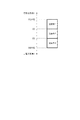
補正ループ制御の動作の設定を図5を用いて説明する。まず、定着モータM2の速度は4段階持っており、V1からV4まで設定されている。V1は転写搬送速度Vtより速い速度、またV4は転写搬送速度Vtより遅い速度である。前記速度V1及びV4はシートPの種類、連続通紙枚数、定着温度制御状況に応じた各部品の熱膨張、加圧力のばらつき、ローラ径の公差等の条件を考慮して、どのような状況においても必ずV1>Vt>V4となるように設定することが必要である。 The setting of the correction loop control operation will be described with reference to FIG. First, the speed of the fixing motor M2 has four stages and is set from V1 to V4. V1 is a speed higher than the transfer conveyance speed Vt, and V4 is a speed slower than the transfer conveyance speed Vt. The speeds V1 and V4 are determined in consideration of conditions such as thermal expansion of parts, variation in pressure, tolerance of roller diameter, etc. according to the type of sheet P, the number of continuous sheets to be passed, and the fixing temperature control status. In this case, it is necessary to set V1> Vt> V4.
そして、V1からV4までの間の速度を略等間隔で3つに分割して3つの速度帯を設定する。図5において、V2とV3はV1とV4の間の速度の略等間隔に区切った速度である(V1>V2>V3>V4)。すなわち、ループ検出センサ20のON・OFFの切り換えに応じてV1とV2の速度間でループ制御を行う状態を速度帯1、V2とV3の間でループ制御を行う状態を速度帯2、V3とV4の間でループ制御を行う状態を速度帯3と設定する。
Then, three speed zones are set by dividing the speed between V1 and V4 into three at substantially equal intervals. In FIG. 5, V2 and V3 are speeds divided at substantially equal intervals between the speeds V1 and V4 (V1> V2> V3> V4). That is, according to switching of the
ループ検出センサ20により検出したループ状態に応じ、定着搬送速度vfをループ量が大きいときは速い速度である第1速度に設定してループ量を小さくし、ループ量が小さいときは前記第1速度より遅い第2速度に切り換えてループを大きくするように速度制御する。そして、前記それぞれの速度帯1、2、3は前記第1速度と第2速度が異なる組合せとなっている。前記速度帯1の第1速度はV1であり、第2速度はV2である。前記速度帯2の第1速度はV2であり、第2速度はV3である。前記速度帯3の第1速度はV3であり、第2速度はV4である。なお、前記第1速度、前記第2速度は定着モータの回転速度により決定される。
In accordance with the loop state detected by the
本実施形態では、ループ制御はループ検出センサ20が検出するよう、複数ある速度帯のなかでも第1速度と第2速度が速い速度の組合せである速度帯1から動作を開始する。そして、第1速度V1、第2速度V2に設定し、ループ検出センサ20がOFF(ループ小)を検出すると定着搬送速度Vfを第2速度V2にしてループを増やすように搬送し、ループ検出センサ20がON(ループ大)を検出すると定着搬送速度Vfを第1速度V1に切り換えてループを減らすように搬送する。すなわち、ループ量が所定量内において大きいときは定着搬送速度を第1速度に切り換え、前記ループ量が所定量内において小さいときは第2速度に切り換えてループを所定量内に収めるように制御する。
In the present embodiment, the loop control starts the operation from the
一方、前記速度帯1での速度制御ではループが所定量内に収まらないときは、速度帯を別の速度帯に切り換える。具体的には、前記速度帯1において、ループ検出センサ20がOFF(ループ小)を所定時間以上、本実施形態では100ms以上継続した場合、速度帯1では定着搬送速度Vfが速すぎてループ量が所定量より小さい状態と判断できるので、第1速度と第2速度の組合せが1段階遅い速度帯2に設定を切り換える。同様に速度帯2において、ループ検出センサ20がOFF(ループ小)を100ms以上継続した場合、速度帯2では定着搬送速度Vfが速すぎることが判断できるので、第2速度帯よりも第1速度と第2速度の組み合わせが1段階遅い速度帯を3に設定を切り換える。
On the other hand, in the speed control in the
逆に速度帯2、3に設定してループ制御している場合において、ループ検出センサ20がON(ループ大)を所定時間以上(本実施形態では100ms以上)継続した場合、速度帯2、3では定着搬送速度Vfが遅すぎてループ量が所定量よりも大きい状態と判断できるので、速度帯を速度帯1、2に変更する。そして、速度帯を変更できない場合はそれ以上の変更は行わない。
On the contrary, when loop control is performed with the speed band set to 2 or 3, when the
図6は前記補正ループ制御を実行する手順を示すフローチャートである。まず、画像形成装置が電源ONされた後、画像形成開始の信号が入力されると(S11)、転写部と定着部の動作を行う(S12、S13)。その後、シートPの先端が定着ニップ部に突入すると(S14)、速度帯1でループ制御を開始する(S15)。速度帯1で動作中、ループ検出センサ20がOFF(ループ小)を100ms継続した場合、すなわち速度帯1の遅い方の速度V2が100ms継続した場合(S16、Yes)、速度を遅い速度帯2での制御に設定を切り換える(S17)。また、速度帯2で動作中、ループ検出センサ20がOFF(ループ小)を100ms継続した場合(S18)、すなわち遅い速度V3を100ms継続し続けた場合Yesとなり、速度を遅い速度帯3での制御に設定を切り換える(S19)。
FIG. 6 is a flowchart showing a procedure for executing the correction loop control. First, when an image formation start signal is input after the image forming apparatus is powered on (S11), the transfer unit and the fixing unit are operated (S12, S13). Thereafter, when the leading edge of the sheet P enters the fixing nip portion (S14), loop control is started in the speed zone 1 (S15). If the
反対に、速度帯2で動作中、ループ検出センサ20がON(ループ大)を100ms継続した場合、すなわち速い速度V2を100ms継続し続けた場合(S20、Yes)、定着搬送速度を速度帯2よりも1段階速い速度帯1での制御に設定を切り換える(S15)。同様に、速度帯3で動作中は、ループ検出センサ20がON(ループ大)を100ms継続した場合、すなわち速い速度V2を100ms継続し続けた場合(S21、Yes)、定着搬送速度を速度帯3より1段階速い速度帯2での制御に設定を切り換える(S17)。
On the other hand, when the
いずれの状態でも、シートPの後端が転写ニップ部Tを抜けた時点S22で画像形成は終了となる(S23)。 In any state, the image formation is completed at the point S22 when the trailing edge of the sheet P passes through the transfer nip T (S23).
以上のようにループ制御するときに切り換える定着搬送速度差、すなわち第1速度と第2速度の速度差が小さい組合せである速度帯を複数有し、検出したループ状態に応じて複数の速度帯を順次切り替えてループ制御する。これによってループ制御の定着搬送速度の速度差を小さく設定することができ、シート上でトナーの飛び散り等を抑制することができる。 As described above, there are a plurality of speed bands that are a combination of a fixing conveyance speed difference that is switched when loop control is performed, that is, a speed difference between the first speed and the second speed, and a plurality of speed bands are selected according to the detected loop state. Loop control by switching sequentially. As a result, the difference in the fixing conveyance speed of the loop control can be set small, and the scattering of toner on the sheet can be suppressed.
また、前記制御をトナー像が転写されたシート先端が定着ニップ部に到達してからシート後端が転写ニップ部を通過するまで繰り返す。このため、シート搬送途中で加圧ローラ50等に加熱による膨張等によるローラの外径公差、表面性ばらつき等が生じても適正なループ制御を行うことが可能である。
The above control is repeated until the trailing edge of the sheet passes through the transfer nip portion after the leading edge of the sheet on which the toner image has been transferred reaches the fixing nip portion. For this reason, it is possible to perform appropriate loop control even if the outer diameter tolerance, surface property variation, etc. of the roller due to expansion due to heating or the like occur in the
M1 …メインモータ
M2 …定着モータ
N …定着ニップ部
P …シート
T …転写ニップ部
1 …感光ドラム
4 …転写ローラ
5 …搬送ガイド
7 …定着器
8 …ステイ
9 …定着フィルム
20 …ループ検出センサ
21 …検出フラグ
21A …揺動軸
21B …遮光フラグ
22 …フォトインタラプタ
40 …ヒータ
50 …加圧ローラ
M1 ... Main motor M2 ... Fixing motor N ... Fixing nip part P ... Sheet T ... Transfer nip
Claims (10)
シートに転写されたトナー像を、シートを定着搬送速度で搬送しつつ定着させる定着部と、
前記転写部と前記定着部の間に生ずるシートのループ状態を検出するループ検出部と、
前記ループ検出部により検出したループ状態に応じ、前記定着搬送速度を第1速度と前記第1速度より遅い第2速度に切り換えてループ量を制御する制御部と、
を有し、
前記制御部は、前記転写搬送速度よりも遅いシート搬送速度と、前記転写搬送速度よりも速いシート搬送速度の間で、前記第1速度と前記第2速度の組合せである速度帯を複数有し、搬送されるシートのループ状態の変化に応じて前記速度帯を切り換えて前記定着搬送速度を制御することを特徴とする画像形成装置。 A transfer unit that transfers the toner image formed on the image carrier while conveying the sheet at a transfer conveyance speed;
A fixing unit that fixes the toner image transferred to the sheet while conveying the sheet at a fixing conveyance speed;
A loop detection unit for detecting a loop state of the sheet generated between the transfer unit and the fixing unit;
A control unit that controls a loop amount by switching the fixing conveyance speed between a first speed and a second speed that is slower than the first speed according to a loop state detected by the loop detection unit;
Have
The control unit includes a plurality of speed bands that are combinations of the first speed and the second speed between a sheet conveyance speed slower than the transfer conveyance speed and a sheet conveyance speed faster than the transfer conveyance speed. An image forming apparatus, wherein the fixing conveyance speed is controlled by switching the speed band in accordance with a change in a loop state of a conveyed sheet.
ことを特徴とする請求項1記載の画像形成装置。 When the loop amount detected by the loop detection unit is large within a predetermined amount, the control unit switches the fixing conveyance speed to the first speed in a set speed band, and when the loop amount is small within the predetermined amount. The image forming apparatus according to claim 1, wherein the first speed is switched to the second speed.
前記ループ検出部が前記ループ量が所定量よりも大きい状態を検出したときは、設定してある速度帯よりも速い速度の組合せの速度帯に設定を切り換え、
前記ループ検出部が前記ループ量が所定量よりも小さい状態を検出したときは、設定してある速度帯よりも遅い速度の組合せの速度帯に設定を切り換える
ことを特徴とする請求項1又は請求項2に記載の画像形成装置。 The plurality of speed zones have a combination in which the first speed and the second speed are slowed down from a fast speed combination,
When the loop detection unit detects a state where the loop amount is larger than a predetermined amount, the setting is switched to a speed band of a combination of speeds faster than a set speed band,
The setting is switched to a speed band of a combination of speeds slower than a set speed band when the loop detection unit detects a state in which the loop amount is smaller than a predetermined amount. Item 3. The image forming apparatus according to Item 2.
前記ループ量が所定量より大きい状態が所定時間以上続くときは設定した速度帯よりも速い速度の組合せの速度帯に設定を切り換え、
前記ループ量が所定量より小さい状態が所定時間以上続くときは設定した速度帯よりも遅い速度の組合せの速度帯に設定を切り換える
ことを特徴とする請求項3記載の画像形成装置。 The controller is
When the state in which the loop amount is larger than a predetermined amount continues for a predetermined time or more, the setting is switched to a speed band of a combination of speeds faster than the set speed band,
The image forming apparatus according to claim 3, wherein when the state where the loop amount is smaller than a predetermined amount continues for a predetermined time or longer, the setting is switched to a speed band of a combination of speeds slower than the set speed band.
V11>V21 かつ V12>V22
の関係を有することを特徴とする請求項1乃至請求項4のいずれか1項に記載の画像形成装置。 There are at least two speed bands, and the first speed band of the first speed band is V11, the second speed is V12, and the second speed band is a combination of speeds slower than the first speed band. When the first speed is V21 and the second speed is V22,
V11> V21 and V12> V22
The image forming apparatus according to claim 1, wherein the image forming apparatus has the following relationship.
V12=V21
の関係を有することを特徴とする請求項5記載の画像形成装置。 The second speed V12 of the first speed zone and the first speed V21 of the second speed zone are:
V12 = V21
The image forming apparatus according to claim 5, wherein:
前記第1速度、前記第2速度は前記モータの回転速度により決定されることを特徴とする請求項1乃至請求項9のいずれか1項に記載の画像形成装置。 The fixing unit conveys a sheet by rotating a roller by a motor,
The image forming apparatus according to claim 1, wherein the first speed and the second speed are determined by a rotational speed of the motor.
Priority Applications (2)
| Application Number | Priority Date | Filing Date | Title |
|---|---|---|---|
| JP2017035778A JP2018141867A (en) | 2017-02-28 | 2017-02-28 | Image forming apparatus |
| US15/906,047 US10289051B2 (en) | 2017-02-28 | 2018-02-27 | Image forming apparatus |
Applications Claiming Priority (1)
| Application Number | Priority Date | Filing Date | Title |
|---|---|---|---|
| JP2017035778A JP2018141867A (en) | 2017-02-28 | 2017-02-28 | Image forming apparatus |
Publications (2)
| Publication Number | Publication Date |
|---|---|
| JP2018141867A true JP2018141867A (en) | 2018-09-13 |
| JP2018141867A5 JP2018141867A5 (en) | 2020-04-09 |
Family
ID=63245739
Family Applications (1)
| Application Number | Title | Priority Date | Filing Date |
|---|---|---|---|
| JP2017035778A Pending JP2018141867A (en) | 2017-02-28 | 2017-02-28 | Image forming apparatus |
Country Status (2)
| Country | Link |
|---|---|
| US (1) | US10289051B2 (en) |
| JP (1) | JP2018141867A (en) |
Families Citing this family (1)
| Publication number | Priority date | Publication date | Assignee | Title |
|---|---|---|---|---|
| JP7172503B2 (en) * | 2018-11-27 | 2022-11-16 | 京セラドキュメントソリューションズ株式会社 | Fixing device and image forming device |
Citations (6)
| Publication number | Priority date | Publication date | Assignee | Title |
|---|---|---|---|---|
| US20060140908A1 (en) * | 2003-06-18 | 2006-06-29 | Ertl Hildegund C J | Methods for inducing an immune response via oral administration of an adenovirus |
| JP2006224562A (en) * | 2005-02-21 | 2006-08-31 | Fuji Xerox Co Ltd | Print system |
| JP2007072289A (en) * | 2005-09-08 | 2007-03-22 | Canon Inc | Image forming apparatus and recording medium conveyance control method in image forming apparatus |
| JP2007183571A (en) * | 2005-12-09 | 2007-07-19 | Canon Inc | Image forming apparatus |
| US20080075477A1 (en) * | 2006-09-21 | 2008-03-27 | Edward Lawrence Kiely | Methods for Moving A Media Sheet Within An Image Forming Device |
| JP2015094932A (en) * | 2013-11-14 | 2015-05-18 | キヤノン株式会社 | Image forming apparatus |
Family Cites Families (3)
| Publication number | Priority date | Publication date | Assignee | Title |
|---|---|---|---|---|
| JPH05107966A (en) | 1991-10-15 | 1993-04-30 | Fuji Xerox Co Ltd | Image forming device |
| US7690651B2 (en) * | 2006-02-03 | 2010-04-06 | Canon Kabushiki Kaisha | Image forming apparatus and remaining sheet detection method thereof |
| JP6639251B2 (en) * | 2016-02-05 | 2020-02-05 | キヤノン株式会社 | Image forming device |
-
2017
- 2017-02-28 JP JP2017035778A patent/JP2018141867A/en active Pending
-
2018
- 2018-02-27 US US15/906,047 patent/US10289051B2/en active Active
Patent Citations (6)
| Publication number | Priority date | Publication date | Assignee | Title |
|---|---|---|---|---|
| US20060140908A1 (en) * | 2003-06-18 | 2006-06-29 | Ertl Hildegund C J | Methods for inducing an immune response via oral administration of an adenovirus |
| JP2006224562A (en) * | 2005-02-21 | 2006-08-31 | Fuji Xerox Co Ltd | Print system |
| JP2007072289A (en) * | 2005-09-08 | 2007-03-22 | Canon Inc | Image forming apparatus and recording medium conveyance control method in image forming apparatus |
| JP2007183571A (en) * | 2005-12-09 | 2007-07-19 | Canon Inc | Image forming apparatus |
| US20080075477A1 (en) * | 2006-09-21 | 2008-03-27 | Edward Lawrence Kiely | Methods for Moving A Media Sheet Within An Image Forming Device |
| JP2015094932A (en) * | 2013-11-14 | 2015-05-18 | キヤノン株式会社 | Image forming apparatus |
Also Published As
| Publication number | Publication date |
|---|---|
| US10289051B2 (en) | 2019-05-14 |
| US20180246457A1 (en) | 2018-08-30 |
Similar Documents
| Publication | Publication Date | Title |
|---|---|---|
| JP2014228789A (en) | Fixing device, image forming apparatus, and surface restoration method | |
| WO2016056670A1 (en) | Image forming device | |
| JP2015087738A (en) | Fixing device and image forming apparatus | |
| JP2007072289A (en) | Image forming apparatus and recording medium conveyance control method in image forming apparatus | |
| JP2007011107A (en) | Image forming apparatus | |
| JP2018097118A (en) | Fixing device and image forming apparatus | |
| US8977149B2 (en) | Image forming apparatus | |
| JP2014052461A (en) | Image heating device | |
| JP2004020689A (en) | Image forming device | |
| JP6376929B2 (en) | Image forming apparatus | |
| US10955781B2 (en) | Fixing apparatus, image forming apparatus, and nip width controlling method | |
| JP2018141867A (en) | Image forming apparatus | |
| JP2014238437A (en) | Image forming apparatus | |
| JP2021026084A (en) | Image forming apparatus and program | |
| JP5447057B2 (en) | Image forming apparatus, image forming apparatus control method, and image forming apparatus control program | |
| JP5842797B2 (en) | Image forming apparatus and swing control method | |
| JP6341829B2 (en) | Image forming apparatus | |
| JP2011180216A (en) | Image forming apparatus | |
| JP2010066482A (en) | Fixing device and image forming apparatus | |
| CN110824873A (en) | Image forming apparatus with a toner supply device | |
| JP2005173486A (en) | Image forming apparatus | |
| JP6661894B2 (en) | Fixing device and image forming device | |
| US9329536B1 (en) | Image forming apparatus with built-in cleaning mechanism | |
| JP3605069B2 (en) | Image forming device | |
| JP5589677B2 (en) | Fixing apparatus and image forming apparatus |
Legal Events
| Date | Code | Title | Description |
|---|---|---|---|
| A521 | Request for written amendment filed |
Free format text: JAPANESE INTERMEDIATE CODE: A523 Effective date: 20200220 |
|
| A621 | Written request for application examination |
Free format text: JAPANESE INTERMEDIATE CODE: A621 Effective date: 20200220 |
|
| A977 | Report on retrieval |
Free format text: JAPANESE INTERMEDIATE CODE: A971007 Effective date: 20201223 |
|
| A131 | Notification of reasons for refusal |
Free format text: JAPANESE INTERMEDIATE CODE: A131 Effective date: 20210119 |
|
| A02 | Decision of refusal |
Free format text: JAPANESE INTERMEDIATE CODE: A02 Effective date: 20210907 |