JP2018123776A - Exhaust gas purification device for internal combustion engine - Google Patents
Exhaust gas purification device for internal combustion engine Download PDFInfo
- Publication number
- JP2018123776A JP2018123776A JP2017017354A JP2017017354A JP2018123776A JP 2018123776 A JP2018123776 A JP 2018123776A JP 2017017354 A JP2017017354 A JP 2017017354A JP 2017017354 A JP2017017354 A JP 2017017354A JP 2018123776 A JP2018123776 A JP 2018123776A
- Authority
- JP
- Japan
- Prior art keywords
- filter
- exhaust
- internal combustion
- combustion engine
- flow
- Prior art date
- Legal status (The legal status is an assumption and is not a legal conclusion. Google has not performed a legal analysis and makes no representation as to the accuracy of the status listed.)
- Pending
Links
Images
Classifications
-
- F—MECHANICAL ENGINEERING; LIGHTING; HEATING; WEAPONS; BLASTING
- F01—MACHINES OR ENGINES IN GENERAL; ENGINE PLANTS IN GENERAL; STEAM ENGINES
- F01N—GAS-FLOW SILENCERS OR EXHAUST APPARATUS FOR MACHINES OR ENGINES IN GENERAL; GAS-FLOW SILENCERS OR EXHAUST APPARATUS FOR INTERNAL-COMBUSTION ENGINES
- F01N3/00—Exhaust or silencing apparatus having means for purifying, rendering innocuous, or otherwise treating exhaust
- F01N3/08—Exhaust or silencing apparatus having means for purifying, rendering innocuous, or otherwise treating exhaust for rendering innocuous
- F01N3/10—Exhaust or silencing apparatus having means for purifying, rendering innocuous, or otherwise treating exhaust for rendering innocuous by thermal or catalytic conversion of noxious components of exhaust
- F01N3/18—Exhaust or silencing apparatus having means for purifying, rendering innocuous, or otherwise treating exhaust for rendering innocuous by thermal or catalytic conversion of noxious components of exhaust characterised by methods of operation; Control
- F01N3/20—Exhaust or silencing apparatus having means for purifying, rendering innocuous, or otherwise treating exhaust for rendering innocuous by thermal or catalytic conversion of noxious components of exhaust characterised by methods of operation; Control specially adapted for catalytic conversion
- F01N3/2006—Periodically heating or cooling catalytic reactors, e.g. at cold starting or overheating
- F01N3/2013—Periodically heating or cooling catalytic reactors, e.g. at cold starting or overheating using electric or magnetic heating means
-
- F—MECHANICAL ENGINEERING; LIGHTING; HEATING; WEAPONS; BLASTING
- F01—MACHINES OR ENGINES IN GENERAL; ENGINE PLANTS IN GENERAL; STEAM ENGINES
- F01N—GAS-FLOW SILENCERS OR EXHAUST APPARATUS FOR MACHINES OR ENGINES IN GENERAL; GAS-FLOW SILENCERS OR EXHAUST APPARATUS FOR INTERNAL-COMBUSTION ENGINES
- F01N3/00—Exhaust or silencing apparatus having means for purifying, rendering innocuous, or otherwise treating exhaust
- F01N3/02—Exhaust or silencing apparatus having means for purifying, rendering innocuous, or otherwise treating exhaust for cooling, or for removing solid constituents of, exhaust
- F01N3/021—Exhaust or silencing apparatus having means for purifying, rendering innocuous, or otherwise treating exhaust for cooling, or for removing solid constituents of, exhaust by means of filters
- F01N3/023—Exhaust or silencing apparatus having means for purifying, rendering innocuous, or otherwise treating exhaust for cooling, or for removing solid constituents of, exhaust by means of filters using means for regenerating the filters, e.g. by burning trapped particles
- F01N3/027—Exhaust or silencing apparatus having means for purifying, rendering innocuous, or otherwise treating exhaust for cooling, or for removing solid constituents of, exhaust by means of filters using means for regenerating the filters, e.g. by burning trapped particles using electric or magnetic heating means
-
- F—MECHANICAL ENGINEERING; LIGHTING; HEATING; WEAPONS; BLASTING
- F01—MACHINES OR ENGINES IN GENERAL; ENGINE PLANTS IN GENERAL; STEAM ENGINES
- F01N—GAS-FLOW SILENCERS OR EXHAUST APPARATUS FOR MACHINES OR ENGINES IN GENERAL; GAS-FLOW SILENCERS OR EXHAUST APPARATUS FOR INTERNAL-COMBUSTION ENGINES
- F01N3/00—Exhaust or silencing apparatus having means for purifying, rendering innocuous, or otherwise treating exhaust
- F01N3/02—Exhaust or silencing apparatus having means for purifying, rendering innocuous, or otherwise treating exhaust for cooling, or for removing solid constituents of, exhaust
- F01N3/021—Exhaust or silencing apparatus having means for purifying, rendering innocuous, or otherwise treating exhaust for cooling, or for removing solid constituents of, exhaust by means of filters
- F01N3/023—Exhaust or silencing apparatus having means for purifying, rendering innocuous, or otherwise treating exhaust for cooling, or for removing solid constituents of, exhaust by means of filters using means for regenerating the filters, e.g. by burning trapped particles
- F01N3/0235—Exhaust or silencing apparatus having means for purifying, rendering innocuous, or otherwise treating exhaust for cooling, or for removing solid constituents of, exhaust by means of filters using means for regenerating the filters, e.g. by burning trapped particles using exhaust gas throttling means
-
- F—MECHANICAL ENGINEERING; LIGHTING; HEATING; WEAPONS; BLASTING
- F01—MACHINES OR ENGINES IN GENERAL; ENGINE PLANTS IN GENERAL; STEAM ENGINES
- F01N—GAS-FLOW SILENCERS OR EXHAUST APPARATUS FOR MACHINES OR ENGINES IN GENERAL; GAS-FLOW SILENCERS OR EXHAUST APPARATUS FOR INTERNAL-COMBUSTION ENGINES
- F01N3/00—Exhaust or silencing apparatus having means for purifying, rendering innocuous, or otherwise treating exhaust
- F01N3/02—Exhaust or silencing apparatus having means for purifying, rendering innocuous, or otherwise treating exhaust for cooling, or for removing solid constituents of, exhaust
- F01N3/021—Exhaust or silencing apparatus having means for purifying, rendering innocuous, or otherwise treating exhaust for cooling, or for removing solid constituents of, exhaust by means of filters
- F01N3/033—Exhaust or silencing apparatus having means for purifying, rendering innocuous, or otherwise treating exhaust for cooling, or for removing solid constituents of, exhaust by means of filters in combination with other devices
- F01N3/035—Exhaust or silencing apparatus having means for purifying, rendering innocuous, or otherwise treating exhaust for cooling, or for removing solid constituents of, exhaust by means of filters in combination with other devices with catalytic reactors
-
- F—MECHANICAL ENGINEERING; LIGHTING; HEATING; WEAPONS; BLASTING
- F01—MACHINES OR ENGINES IN GENERAL; ENGINE PLANTS IN GENERAL; STEAM ENGINES
- F01N—GAS-FLOW SILENCERS OR EXHAUST APPARATUS FOR MACHINES OR ENGINES IN GENERAL; GAS-FLOW SILENCERS OR EXHAUST APPARATUS FOR INTERNAL-COMBUSTION ENGINES
- F01N9/00—Electrical control of exhaust gas treating apparatus
- F01N9/002—Electrical control of exhaust gas treating apparatus of filter regeneration
-
- F—MECHANICAL ENGINEERING; LIGHTING; HEATING; WEAPONS; BLASTING
- F01—MACHINES OR ENGINES IN GENERAL; ENGINE PLANTS IN GENERAL; STEAM ENGINES
- F01N—GAS-FLOW SILENCERS OR EXHAUST APPARATUS FOR MACHINES OR ENGINES IN GENERAL; GAS-FLOW SILENCERS OR EXHAUST APPARATUS FOR INTERNAL-COMBUSTION ENGINES
- F01N2240/00—Combination or association of two or more different exhaust treating devices, or of at least one such device with an auxiliary device, not covered by indexing codes F01N2230/00 or F01N2250/00, one of the devices being
- F01N2240/36—Combination or association of two or more different exhaust treating devices, or of at least one such device with an auxiliary device, not covered by indexing codes F01N2230/00 or F01N2250/00, one of the devices being an exhaust flap
-
- F—MECHANICAL ENGINEERING; LIGHTING; HEATING; WEAPONS; BLASTING
- F01—MACHINES OR ENGINES IN GENERAL; ENGINE PLANTS IN GENERAL; STEAM ENGINES
- F01N—GAS-FLOW SILENCERS OR EXHAUST APPARATUS FOR MACHINES OR ENGINES IN GENERAL; GAS-FLOW SILENCERS OR EXHAUST APPARATUS FOR INTERNAL-COMBUSTION ENGINES
- F01N2430/00—Influencing exhaust purification, e.g. starting of catalytic reaction, filter regeneration, or the like, by controlling engine operating characteristics
-
- F—MECHANICAL ENGINEERING; LIGHTING; HEATING; WEAPONS; BLASTING
- F01—MACHINES OR ENGINES IN GENERAL; ENGINE PLANTS IN GENERAL; STEAM ENGINES
- F01N—GAS-FLOW SILENCERS OR EXHAUST APPARATUS FOR MACHINES OR ENGINES IN GENERAL; GAS-FLOW SILENCERS OR EXHAUST APPARATUS FOR INTERNAL-COMBUSTION ENGINES
- F01N2900/00—Details of electrical control or of the monitoring of the exhaust gas treating apparatus
- F01N2900/06—Parameters used for exhaust control or diagnosing
- F01N2900/14—Parameters used for exhaust control or diagnosing said parameters being related to the exhaust gas
- F01N2900/1411—Exhaust gas flow rate, e.g. mass flow rate or volumetric flow rate
-
- F—MECHANICAL ENGINEERING; LIGHTING; HEATING; WEAPONS; BLASTING
- F01—MACHINES OR ENGINES IN GENERAL; ENGINE PLANTS IN GENERAL; STEAM ENGINES
- F01N—GAS-FLOW SILENCERS OR EXHAUST APPARATUS FOR MACHINES OR ENGINES IN GENERAL; GAS-FLOW SILENCERS OR EXHAUST APPARATUS FOR INTERNAL-COMBUSTION ENGINES
- F01N2900/00—Details of electrical control or of the monitoring of the exhaust gas treating apparatus
- F01N2900/06—Parameters used for exhaust control or diagnosing
- F01N2900/16—Parameters used for exhaust control or diagnosing said parameters being related to the exhaust apparatus, e.g. particulate filter or catalyst
- F01N2900/1606—Particle filter loading or soot amount
-
- Y—GENERAL TAGGING OF NEW TECHNOLOGICAL DEVELOPMENTS; GENERAL TAGGING OF CROSS-SECTIONAL TECHNOLOGIES SPANNING OVER SEVERAL SECTIONS OF THE IPC; TECHNICAL SUBJECTS COVERED BY FORMER USPC CROSS-REFERENCE ART COLLECTIONS [XRACs] AND DIGESTS
- Y02—TECHNOLOGIES OR APPLICATIONS FOR MITIGATION OR ADAPTATION AGAINST CLIMATE CHANGE
- Y02T—CLIMATE CHANGE MITIGATION TECHNOLOGIES RELATED TO TRANSPORTATION
- Y02T10/00—Road transport of goods or passengers
- Y02T10/10—Internal combustion engine [ICE] based vehicles
- Y02T10/12—Improving ICE efficiencies
-
- Y—GENERAL TAGGING OF NEW TECHNOLOGICAL DEVELOPMENTS; GENERAL TAGGING OF CROSS-SECTIONAL TECHNOLOGIES SPANNING OVER SEVERAL SECTIONS OF THE IPC; TECHNICAL SUBJECTS COVERED BY FORMER USPC CROSS-REFERENCE ART COLLECTIONS [XRACs] AND DIGESTS
- Y02—TECHNOLOGIES OR APPLICATIONS FOR MITIGATION OR ADAPTATION AGAINST CLIMATE CHANGE
- Y02T—CLIMATE CHANGE MITIGATION TECHNOLOGIES RELATED TO TRANSPORTATION
- Y02T10/00—Road transport of goods or passengers
- Y02T10/10—Internal combustion engine [ICE] based vehicles
- Y02T10/40—Engine management systems
Landscapes
- Engineering & Computer Science (AREA)
- Chemical & Material Sciences (AREA)
- Combustion & Propulsion (AREA)
- Mechanical Engineering (AREA)
- General Engineering & Computer Science (AREA)
- Chemical Kinetics & Catalysis (AREA)
- Health & Medical Sciences (AREA)
- Toxicology (AREA)
- Processes For Solid Components From Exhaust (AREA)
- Exhaust Gas After Treatment (AREA)
- Exhaust Gas Treatment By Means Of Catalyst (AREA)
Abstract
【課題】ウォールフロー型のフィルタに堆積したPMを好適に酸化除去することを目的とする。【解決手段】ウォールフロー型のフィルタと、フィルタを下流側から昇温させる昇温手段と、排気シャット弁と、排気流量が所定流量以上である場合に、排気シャット弁を一旦全閉にした後全開にすることでフィルタにおける排気流れを制御し、該フィルタに堆積したPMを該フィルタにおける下流側の部分に移動させる制御手段と、制御手段がPMを前記下流側の部分に移動させた後において、昇温手段を用いてフィルタに堆積したPMを酸化除去する処理である再生処理を実行する処理手段と、を備える。【選択図】図4An object of the present invention is to suitably oxidize and remove PM deposited on a wall flow type filter. A wall flow type filter, a temperature raising means for raising the temperature of the filter from the downstream side, an exhaust shut-off valve, and an exhaust shut-off valve once fully closed when the exhaust flow rate is equal to or higher than a predetermined flow rate A control means for controlling the exhaust flow in the filter by fully opening and moving the PM accumulated on the filter to the downstream portion of the filter; and after the control means has moved the PM to the downstream portion. And a processing means for executing a regeneration process, which is a process for removing the PM deposited on the filter by oxidation using the temperature raising means. [Selection] Figure 4
Description
本発明は、内燃機関の排気浄化装置に関する。 The present invention relates to an exhaust emission control device for an internal combustion engine.
内燃機関の排気通路に、排気中の粒子状物質(以下、「PM」と称する場合もある)を捕集するウォールフロー型のフィルタを設ける技術が知られている。そして、特許文献1には、ウォールフロー型のフィルタを昇温させて該フィルタに堆積したPMを酸化除去する技術が開示されている。
There is known a technique in which a wall flow type filter for collecting particulate matter (hereinafter also referred to as “PM”) in exhaust gas is provided in an exhaust passage of an internal combustion engine.
ウォールフロー型のフィルタにPMが堆積していくと、フィルタの圧力損失が増大するため、フィルタを昇温させPMを酸化除去することで、フィルタの再生が行われる。ここで、PMは、フィルタにおいて排気流れ方向における上流側の部分から下流側の部分に亘って堆積する傾向がある。したがって、フィルタに堆積したPMを酸化除去するためには、フィルタを上流側の部分から下流側の部分に亘って昇温させる必要がある。そうすると、フィルタの昇温対象が広範囲に及ぶことになるため、フィルタの再生に多くのエネルギを要することになる。 When PM accumulates on the wall flow type filter, the pressure loss of the filter increases. Therefore, the filter is regenerated by raising the temperature of the filter and oxidizing and removing the PM. Here, PM tends to accumulate from an upstream portion to a downstream portion in the exhaust flow direction in the filter. Therefore, in order to oxidize and remove PM deposited on the filter, it is necessary to raise the temperature of the filter from the upstream portion to the downstream portion. As a result, the temperature increase target of the filter extends over a wide range, so that much energy is required for regeneration of the filter.
本発明は、上記の問題点に鑑みてなされたものであり、ウォールフロー型のフィルタに堆積したPMを好適に酸化除去することを目的とする。 The present invention has been made in view of the above problems, and an object thereof is to suitably oxidize and remove PM deposited on a wall flow type filter.
本発明は、内燃機関の排気浄化装置に係る発明である。そして、この排気浄化装置は、内燃機関の排気通路に設けられたフィルタであって、排気流れ方向に沿った隔壁により区画された複数のセルを有し、該複数のセルにおいて、排気流れ方向における下流側端部が閉塞され且つ上流側端部が開放されたセルと、排気流れ方向における上流側端部が閉塞され且つ下流側端部が開放されたセルと、が交互に並べられたウォールフロー型のフィルタを備える。 The present invention relates to an exhaust emission control device for an internal combustion engine. The exhaust purification device is a filter provided in an exhaust passage of the internal combustion engine, and has a plurality of cells partitioned by partition walls along the exhaust flow direction. Wall flow in which the downstream end is closed and the upstream end is opened, and the cell in which the upstream end in the exhaust flow direction is closed and the downstream end is open are arranged alternately. With a filter of the type.
このようなフィルタにおいて、或る一部分に集中してPMを堆積させることができれば、PMが集中して堆積している部分を昇温させることで、フィルタの再生を行うことができる。また、フィルタにおけるPMの堆積密度が高い部分においては、PMの堆積密度が低い部分よりも、フィルタの再生時にPMが連続的に延焼する傾向がある。つまり、フィルタの或る一部分に集中してPMを堆積させることができれば、PMが集中して堆積している部分を昇温させることによって、フィルタ全体を昇温させる場合よりも、少ないエネルギで短時間にフィルタの再生を行うことができる。 In such a filter, if PM can be concentrated and deposited on a certain portion, the filter can be regenerated by raising the temperature of the portion where PM is concentrated and deposited. Further, in the part where the PM deposition density is high in the filter, the PM tends to continuously spread during regeneration of the filter than in the part where the PM deposition density is low. In other words, if PM can be concentrated on a certain part of the filter, the temperature of the part where PM is concentrated and deposited can be raised to lower the temperature with less energy than when the entire filter is heated. The filter can be regenerated in time.
そこで、本発明に係る内燃機関の排気浄化装置は、前記フィルタを排気流れ方向における下流側から昇温させる昇温手段と、前記フィルタよりも下流の前記排気通路に設けられ、全開、全閉を切替えて弁を開閉するように構成されている排気シャット弁と、排気流量が所定流量以上である場合に、前記排気シャット弁を一旦全閉にした後全開にすることで前記フィルタにおける排気流れを制御し、該フィルタに堆積した粒子状物質を該フィルタ
において排気流れ方向における下流側の部分に移動させる制御手段と、前記制御手段が粒子状物質を前記下流側の部分に移動させた後において、前記昇温手段を用いて前記フィルタに堆積した粒子状物質を酸化除去する処理である再生処理を実行する処理手段と、を備える。
Therefore, the exhaust gas purification apparatus for an internal combustion engine according to the present invention is provided with a temperature raising means for raising the temperature of the filter from the downstream side in the exhaust flow direction and the exhaust passage downstream of the filter, and is fully opened and fully closed. An exhaust shut-off valve configured to switch to open and close the valve, and when the exhaust flow rate is greater than or equal to a predetermined flow rate, the exhaust shut-off valve is temporarily closed and then fully open to thereby reduce the exhaust flow in the filter. Controlling and moving the particulate matter deposited on the filter to a downstream portion in the exhaust flow direction in the filter, and after the control means moves the particulate matter to the downstream portion, Processing means for executing regeneration processing, which is processing for oxidizing and removing particulate matter deposited on the filter using the temperature raising means.
排気シャット弁は、制御手段による排気流れの制御が実行されていない内燃機関の通常運転時(以下、単に「通常運転時」と称する場合もある。)には全開にされている。そして、通常運転時には、内燃機関から排出された排気は、脈動を伴って排気通路における上流側から下流側に流れている。以下の説明において、排気流れにおける上流側から下流側への流れを「順流」と称し、下流側から上流側への流れを「逆流」と称する。ここで、制御手段が、排気シャット弁を一時的に全閉状態に制御すると、排気通路における排気流れが一時的に逆流し得る。または、排気流れは順流のままでも、脈動の大きさが一時的に増大し得る。そして、このように排気通路における排気流れが比較的大きく変化すると、フィルタ内における排気流れも変化し得る。 The exhaust shut-off valve is fully opened during normal operation of the internal combustion engine in which the control of the exhaust flow by the control means is not executed (hereinafter sometimes referred to simply as “normal operation”). During normal operation, the exhaust discharged from the internal combustion engine flows from the upstream side to the downstream side in the exhaust passage with pulsation. In the following description, the flow from the upstream side to the downstream side in the exhaust flow is referred to as “forward flow”, and the flow from the downstream side to the upstream side is referred to as “back flow”. Here, when the control means temporarily controls the exhaust shut-off valve to the fully closed state, the exhaust flow in the exhaust passage may temporarily reverse. Or, even if the exhaust flow remains in the forward flow, the magnitude of the pulsation may temporarily increase. When the exhaust flow in the exhaust passage changes relatively large in this way, the exhaust flow in the filter can also change.
ここで、フィルタの隔壁におけるPMの堆積状態に着目すると、通常運転時には、排気は隔壁の一方の表面の側から壁内を通過して他方の表面の側に流れる傾向にあるため、PMは隔壁の該一方の表面および壁内に堆積し易くなる。一方、制御手段が排気シャット弁を一時的に全閉状態に制御すると、フィルタ内における排気流れが変化し得る。詳しくは、前記制御によって排気通路における排気流れが一時的に逆流する場合には、隔壁を通過する排気も一時的に通常運転時とは逆(すなわち、隔壁の前記他方の表面の側から前記一方の表面の側)に流れる。また、排気流れは順流のままで脈動の大きさが一時的に増大する場合にも、隔壁を通過する排気が一時的に通常運転時とは逆に流れ得る。なぜなら、その大きさが増大した脈動の影響により、隔壁の前記一方の表面の側の圧力が前記他方の表面の側の圧力よりも低くなることがあり、フィルタ内における排気流れに乱れが生じ易くなるからである。そして、隔壁を通過する排気が一時的に通常運転時とは逆に流れるようなフィルタ内の排気流れの乱れが生じると、隔壁に堆積したPMが該隔壁から剥離し易くなる。 Here, paying attention to the accumulation state of PM in the partition wall of the filter, during normal operation, exhaust gas tends to flow from the one surface side of the partition wall through the wall and flow to the other surface side. It tends to deposit on the one surface and wall of the glass. On the other hand, when the control means temporarily controls the exhaust shut-off valve to the fully closed state, the exhaust flow in the filter can change. Specifically, when the exhaust flow in the exhaust passage temporarily reverses due to the control, the exhaust gas passing through the partition wall is also temporarily opposite to that during normal operation (that is, the one side from the other surface side of the partition wall). Flow to the surface side). Further, even when the exhaust flow remains a forward flow and the magnitude of the pulsation temporarily increases, the exhaust passing through the partition wall may temporarily flow in the opposite direction to that during normal operation. This is because the pressure on the one surface side of the partition wall may be lower than the pressure on the other surface side due to the influence of the pulsation whose size has increased, and the exhaust flow in the filter is likely to be disturbed. Because it becomes. When the exhaust flow in the filter is disturbed such that the exhaust gas passing through the partition wall temporarily flows in the direction opposite to that during normal operation, PM deposited on the partition wall is easily separated from the partition wall.
ところで、通常運転時においては、排気流量が多いときは少ないときよりも、PMは、フィルタにおける下流側の部分(以下、「フィルタの下流側部分」と称する場合もある。)に堆積し易くなる。制御手段は、この傾向を利用して、排気シャット弁を一時的に全閉状態に制御することによって隔壁から剥離させたPMをフィルタの下流側部分に移動させることができる。これについて、以下に説明する。上述したように、排気シャット弁を一時的に全閉状態に制御すると、隔壁を通過する排気が一時的に通常運転時とは逆に流れるようなフィルタ内の排気流れの乱れが生じ易くなる。ここで、フィルタ内の排気流れにこのような乱れが生じたままとなると、隔壁から剥離させたPMをフィルタの所望の部分に堆積させ難くなる。そこで、制御手段は、全閉状態の排気シャット弁を全開状態に制御することによって、局所的に逆流が生じていたフィルタ内の流れを順流に戻す。詳しくは、制御手段は、排気流量が所定流量以上である場合に、排気シャット弁の制御を行うことによって、フィルタ内に所定流量以上の順流を生じさせる。その結果、剥離したPMが、フィルタの下流側部分に移動することになる。なお、所定流量とは、隔壁から剥離したPMをフィルタの下流側部分に移動させることができる流量として定義される。 By the way, during normal operation, when the exhaust gas flow rate is large, PM is more likely to accumulate in the downstream portion of the filter (hereinafter sometimes referred to as “the downstream portion of the filter”). . Using this tendency, the control means can move the PM separated from the partition wall to the downstream portion of the filter by temporarily controlling the exhaust shut-off valve to the fully closed state. This will be described below. As described above, when the exhaust shut-off valve is temporarily controlled to be fully closed, the exhaust flow in the filter is likely to be disturbed such that the exhaust passing through the partition wall temporarily flows in the opposite direction to that during normal operation. Here, if such a disturbance remains in the exhaust flow in the filter, it becomes difficult to deposit the PM peeled off from the partition wall on a desired portion of the filter. Therefore, the control means controls the exhaust shut valve in the fully closed state to the fully open state, thereby returning the flow in the filter in which the back flow locally occurs to the forward flow. Specifically, when the exhaust gas flow rate is equal to or higher than a predetermined flow rate, the control unit controls the exhaust shut valve to generate a forward flow that exceeds the predetermined flow rate in the filter. As a result, the peeled PM moves to the downstream portion of the filter. The predetermined flow rate is defined as a flow rate at which the PM peeled off from the partition wall can be moved to the downstream portion of the filter.
そして、制御手段がフィルタにおける排気流れを制御してPMをフィルタの下流側部分に移動させた後において、処理手段が再生処理を実行することによって、フィルタの再生が行われる。上述したように、再生処理は昇温手段を用いて実行されるため、再生処理では、フィルタが下流側から、すなわち排気流れの制御によって移動したPMが集中して堆積している側から昇温されることになる。このように、フィルタの下流側部分に集中して堆積したPMを酸化除去する場合には、PMが連続的に延焼し易くなる。なお、昇温手段
として、電気加熱装置等の周知の構成を用いることができる。
And after a control means controls the exhaust flow in a filter and moves PM to the downstream part of a filter, regeneration of a filter is performed when a processing means performs regeneration processing. As described above, since the regeneration process is performed using the temperature raising means, in the regeneration process, the temperature of the filter is increased from the downstream side, that is, from the side where the PM that has been moved and accumulated by controlling the exhaust flow is concentrated. Will be. As described above, when the PM accumulated in the downstream portion of the filter is removed by oxidation, the PM easily spreads continuously. As the temperature raising means, a known configuration such as an electric heating device can be used.
以上のようなフィルタの再生においては、少ないエネルギで短時間にフィルタの再生を行うことができる。つまり、本発明に係る内燃機関の排気浄化装置は、フィルタに堆積したPMを好適に酸化除去することを可能とする。 In the filter regeneration as described above, the filter can be regenerated in a short time with less energy. That is, the exhaust gas purification apparatus for an internal combustion engine according to the present invention can suitably oxidize and remove PM deposited on the filter.
また、前記フィルタは、前記隔壁に選択還元型NOx触媒が担持されたSCRフィルタであってもよい。ここで、選択還元型NOx触媒は、PMが酸化除去され得る温度に曝されると劣化し易くなる傾向がある。そこで、本発明に係るSCRフィルタは、該選択還元型NOx触媒が、該フィルタにおいて排気流れ方向における下流側の所定の部分よりも上流側に担持されていることを特徴とする。ここで、前記所定の部分とは、排気流れの制御によって移動したPMが集中して堆積する部分である。上述した再生処理によるフィルタの再生においては、このような下流側の所定の部分が昇温され易くなる。すなわち、再生処理の実行中において、選択還元型NOx触媒が担持されている上流側の部分は、前記所定の部分よりも温度が低くなる傾向にある。つまり、選択還元型NOx触媒が、PMの酸化除去の際に、該選択還元型NOx触媒が劣化し得る温度に曝される事態が生じ難くなる。 Further, the filter may be an SCR filter in which a selective reduction type NOx catalyst is supported on the partition wall. Here, the selective reduction type NOx catalyst tends to be easily deteriorated when exposed to a temperature at which PM can be oxidized and removed. Therefore, the SCR filter according to the present invention is characterized in that the selective reduction type NOx catalyst is supported on the upstream side of a predetermined portion on the downstream side in the exhaust flow direction in the filter. Here, the predetermined portion is a portion where the PM that has moved by controlling the exhaust flow is concentrated and accumulated. In the regeneration of the filter by the regeneration process described above, the temperature of such a predetermined portion on the downstream side is likely to be increased. That is, during the regeneration process, the temperature of the upstream portion on which the selective reduction type NOx catalyst is supported tends to be lower than that of the predetermined portion. That is, it is difficult for the selective reduction type NOx catalyst to be exposed to a temperature at which the selective reduction type NOx catalyst may deteriorate during the oxidation removal of PM.
このようなSCRフィルタにおけるフィルタの再生では、少ないエネルギで短時間にフィルタの再生を行うことができるとともに、フィルタの再生に伴う選択還元型NOx触媒の劣化が抑制される。したがって、フィルタに堆積したPMを好適に酸化除去することができる。 In the regeneration of the filter in such an SCR filter, the regeneration of the filter can be performed in a short time with less energy, and the deterioration of the selective reduction type NOx catalyst accompanying the regeneration of the filter is suppressed. Therefore, PM deposited on the filter can be suitably oxidized and removed.
また、前記処理手段は、前記内燃機関の停止中に前記再生処理を行ってもよい。この場合、内燃機関の運転中に制御手段による処理が行われ、その後、内燃機関が停止したときに再生処理が行われることになる。このように、内燃機関の停止中に再生処理を行うことによって、再生処理が選択還元型NOx触媒によるNOx浄化に影響を及ぼしてしまうことを排除することができる。 The processing means may perform the regeneration process while the internal combustion engine is stopped. In this case, processing by the control means is performed during operation of the internal combustion engine, and then regeneration processing is performed when the internal combustion engine stops. In this way, by performing the regeneration process while the internal combustion engine is stopped, it is possible to eliminate the influence of the regeneration process on the NOx purification by the selective reduction type NOx catalyst.
本発明によれば、ウォールフロー型のフィルタに堆積したPMを好適に酸化除去することができる。 According to the present invention, PM deposited on a wall flow type filter can be suitably oxidized and removed.
以下に図面を参照して、この発明を実施するための形態を、実施例に基づいて例示的に詳しく説明する。ただし、この実施例に記載されている構成部品の寸法、材質、形状、その相対配置などは、特に記載がない限りは、この発明の範囲をそれらのみに限定する趣旨のものではない。 DESCRIPTION OF EMBODIMENTS Hereinafter, embodiments for carrying out the present invention will be exemplarily described in detail with reference to the drawings. However, the dimensions, materials, shapes, relative arrangements, and the like of the components described in this embodiment are not intended to limit the scope of the present invention only to those unless otherwise specified.
<実施例1>
以下、図面を用いて本発明の第1の実施例について説明する。図1は、本実施例に係る内燃機関とその吸排気系の概略構成を示す図である。図1に示す内燃機関1は、軽油を燃料とする圧縮着火式の内燃機関(ディーゼルエンジン)である。ただし、本発明は、ガソリン等を燃料とする火花点火式の内燃機関にも適用することができる。
<Example 1>
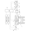
Hereinafter, a first embodiment of the present invention will be described with reference to the drawings. FIG. 1 is a diagram showing a schematic configuration of an internal combustion engine and its intake / exhaust system according to the present embodiment. An
内燃機関1は、気筒2内へ燃料を噴射する燃料噴射弁3を備えている。なお、内燃機関1が火花点火式の内燃機関である場合は、燃料噴射弁3は、吸気ポートへ燃料を噴射するように構成されてもよい。
The
内燃機関1は吸気通路4と接続されている。吸気通路4には、エアフローメータ40およびスロットル弁41が設けられている。エアフローメータ40は、吸気通路4内を流れる吸気(空気)の量(質量)に応じた電気信号を出力する。スロットル弁41は、吸気通路4におけるエアフローメータ40よりも下流側に配置されている。スロットル弁41は、吸気通路4内の通路断面積を変更することで、内燃機関1の吸入空気量を調整する。
The
内燃機関1は排気通路5と接続されている。排気通路5には排気の流れに従って順に、フィルタケース50、第一温度センサ55、尿素水添加弁54、触媒ケース51、NOxセンサ56、および排気シャット弁53が設けられている。フィルタケース50は、略筒状のケース内にパティキュレートフィルタ50a(以下、「フィルタ50a」と称する場合もある。)を収容している。また、フィルタケース50は、フィルタ50aよりも下流側に電気加熱装置52を収容している。フィルタ50aは、ウォールフロー型のフィルタであり、排気中のPMを捕集するために、その基材は多孔質体を有している。なお、フィルタ50aの詳細については後述する。また、本実施例における電気加熱装置52は、電熱線ヒーターである。この電熱線ヒーターに通電することによって、フィルタ50aを下流側から昇温させることができる。なお、このようにフィルタ50aを下流側から昇温させることができる構成であれば周知の構成を用いることができ、例えば、電圧の印加によりフィルタ50aの基材を抵抗体として発熱させる構成を用いてもよい。なお、本実施例においては電気加熱装置52が、本発明における昇温手段に相当する。
The
また、触媒ケース51は、略筒状のケース内に選択還元型NOx触媒51a(以下、「SCR触媒51a」と称する場合もある。)を収容している。SCR触媒51aは、アンモニアを還元剤として排気中のNOxを還元する機能を有する。ここで、SCR触媒51aよりも上流側に設けられている尿素水添加弁54は、排気通路5内を流れる排気中に尿素水を添加し、該尿素水がSCR触媒51aに供給される。つまり、SCR触媒51aに、アンモニアの前駆体である尿素が供給される。そして、供給された尿素が加水分解されることで生成されたアンモニアがSCR触媒51aに吸着する。このSCR触媒51aに吸着したアンモニアを還元剤として、排気中のNOxが還元される。なお、尿素水添加弁54に代えて、アンモニアガスを排気中に添加するアンモニア添加弁を設けてもよい。
Further, the
また、第一温度センサ55は、排気の温度に応じた電気信号を出力し、NOxセンサ56は、排気中のNOx濃度に応じた電気信号を出力する。また、排気シャット弁53は、全開・全閉を切替えて弁を開閉するように構成されている。なお、排気シャット弁53は、制御上の全閉時であっても、該排気シャット弁53よりも下流の排気通路5へ比較的少ない量の排気が構造的に流出し得る。
The
そして、内燃機関1には電子制御ユニット(ECU)10が併設されている。ECU10は、内燃機関1の運転状態等を制御するユニットである。ECU10には、上記のエアフローメータ40、第一温度センサ55、およびNOxセンサ56に加え、アクセルポジションセンサ7、クランクポジションセンサ8等の各種センサが電気的に接続されている。アクセルポジションセンサ7は、図示しないアクセルペダルの操作量(アクセル開度)に相関した電気信号を出力するセンサである。クランクポジションセンサ8は、内燃機関1の機関出力軸(クランクシャフト)の回転位置に相関する電気信号を出力するセンサである。そして、これらのセンサの出力信号がECU10に入力される。ECU10は、アクセルポジションセンサ7の出力信号に基づいて内燃機関1の機関負荷を導出し、クランクポジションセンサ8の出力信号に基づいて内燃機関1の機関回転速度を導出する。また、ECU10は、エアフローメータ40の出力値に基づいて内燃機関1から排出される排気の流量(以下、「排気流量」と称する場合もある。)を推定する。
The
また、ECU10には、上記の燃料噴射弁3、スロットル弁41、電気加熱装置52、排気シャット弁53、および尿素水添加弁54等の各種機器が電気的に接続されている。そして、ECU10は、これら各種機器を制御する。例えば、ECU10は、電気加熱装置52を作動することによって、フィルタ50aを下流側から昇温させることができる。そして、フィルタ50aにおいて、その温度が所定温度(例えば、600℃)以上となった部分では、基材に捕集されたPMが燃焼する。
The
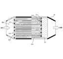
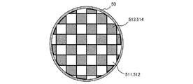
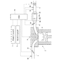
次に、図2および図3に基づいて、フィルタ50aの構造について説明する。図2はフィルタ50aの概略構成を示す縦断面図であり、図3はフィルタ50aの概略構成を示す横断面図である。図2および図3に示すように、フィルタケース50内にフィルタ50aを構成する円柱状の基材510が内装されている。基材510には、軸方向(排気の流れ方向)に延在する複数の通路511、512が形成されるとともに、それら複数の通路511、512がハニカム状に配置されている。言い換えると、基材510は、ハニカム状に配置される複数の通路511、512を画定するように形成されている。なお、図2、3に示す通路511、512の本数は一例に過ぎず、それら通路511、512の本数は車両や内燃機関の諸元に応じて適宜決定されればよい。
Next, the structure of the
複数の通路511、512のうち、一部の通路511は、排気の流れ方向における上流側端部が栓体513により閉塞されている。複数の通路511、512のうち、残りの通路512は、排気の流れ方向における下流側端部が栓体514により閉塞されている。なお、通路511と通路512は、交互に配置されている。これにより、ウォールフロー型のフィルタが形成される。以下では、通路511を第1通路511と称し、通路512を第2通路512と称する。
Among the plurality of
基材510において、第1通路511と第2通路512の間に位置する隔壁515は、多孔質体により形成されている。なお、基材510のうちの隔壁515のみが多孔質体により形成されてもよく、栓体513、514を含む基材510の全体が多孔質体により形成されていてもよい。ここでいう多孔質体の材料としては、排気中のPMを捕集するのに適した公知の材料を採用することができる。
In the
そして、このようなフィルタ50aによって、排気中のPMが捕集され、捕集されたP
Mは基材510に堆積する。このようにフィルタ50aにPMが堆積していくと、フィルタ50aの圧力損失が増大するため、フィルタ50aを昇温させPMを酸化除去することで、フィルタ50aの再生が行われる。ここで、PMは、フィルタ50aにおいて上流側の部分から下流側の部分に亘って堆積する傾向がある。したがって、フィルタ50aに堆積したPMを酸化除去するためには、フィルタ50aを上流側の部分から下流側の部分に亘って広範囲に昇温させる必要があり、フィルタ50aの再生に多くのエネルギを要することになる。一方で、このようなフィルタ50aにおいて、或る一部分に集中してPMを堆積させることができれば、PMが集中して堆積している部分を昇温させることによって、全体を昇温させる場合よりも、少ないエネルギで短時間にフィルタ50aの再生を行うことができる。
The PM in the exhaust gas is collected by such a
M is deposited on the
そこで、ECU10は、排気流量が所定流量以上である場合に、排気シャット弁53を一旦全閉にした後全開にすることでフィルタ50aにおける排気流れを制御し、フィルタ50aに堆積したPMを、フィルタ50aにおける下流側の部分(以下、「フィルタの下流側部分」と称する場合もある。)に移動させる。このように、PMを下流側の部分に移動させるために行う排気流れの制御を「排気流れ制御」と称する。なお、ECU10が排気流れ制御を実行することで、本発明に係る制御手段として機能する。
Therefore, when the exhaust flow rate is equal to or higher than the predetermined flow rate, the
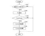
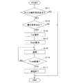
ここで、ECU10が実行する排気流れ制御の制御フローについて図4に基づいて説明する。図4は、排気流れ制御の制御フローを示すフローチャートである。本実施例では、ECU10によって、本フローが内燃機関1の運転中に所定の演算周期で繰り返し実行される。つまり、排気流れ制御は、フィルタ50aの再生要求が成立しているか否かにかかわらず、実行されることになる。
Here, the control flow of the exhaust flow control executed by the
本フローでは、先ず、S101において、燃料カット処理の実行中であるか否かが判別される。そして、S101において肯定判定された場合、ECU10はS102の処理へ進み、S101において否定判定された場合、本フローの実行が終了される。仮に燃料カット処理が実行されていない場合に排気流れ制御が実行されると、一時的に閉弁された排気シャット弁53の影響により内燃機関1の背圧が変化し、気筒2内での燃焼等に影響を及ぼす場合がある。そのため、本フローでは、燃料カット処理の実行中でない場合には、排気流れ制御が実行されないとしている。ただし、燃料カット処理の実行中にのみ排気流れ制御が行われると限定する意図はない。ECU10が排気シャット弁53の制御を行ったとしても、内燃機関1の運転に悪影響を及ぼさない場合には、燃料カット処理が実行されていないときであってもECU10は該制御を行うことができる。この場合には、S101において、燃料カット処理の実行中であるか否かの判別に代えて、排気シャット弁53の制御を行ったとしても内燃機関1の運転に悪影響を及ぼさないか否かが判別される。
In this flow, first, in S101, it is determined whether or not a fuel cut process is being executed. If an affirmative determination is made in S101, the
S101において肯定判定された場合、次に、S102において、排気流量Freが算出される。S102では、エアフローメータ40の出力値に基づいて、排気流量Freが算出される。なお、S102の処理は、燃料カット処理の実行中に行われるため、S102で算出される排気流量Freは、内燃機関1から排出される空気の流量である。そして、S103において、S102で算出した排気流量Freが所定の閾値Freth以上であるか否かが判別される。ここで、所定の閾値Frethは、後述するS104の処理によりフィルタ50aの隔壁515から剥離したPMを、後述するS105の処理によりフィルタの下流側部分に移動させることができる流量として定義される。なお、所定の閾値Frethが、本発明における所定流量に相当する。そして、S103において肯定判定された場合、ECU10はS104の処理へ進み、S103において否定判定された場合、本フローの実行が終了される。
If an affirmative determination is made in S101, the exhaust flow rate Fre is then calculated in S102. In S102, the exhaust flow rate Fre is calculated based on the output value of the
S103において肯定判定された場合、次に、S104において、全開状態の排気シャ
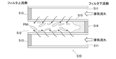
ット弁53を全閉状態に制御する処理が実行される。その結果、フィルタ50a内の排気流れに一時的な乱れが生じ、隔壁515に堆積したPMが剥離する。これについて、図5Aおよび図5Bを用いて説明する。図5Aは、S104の処理によって排気通路5における排気流れが一時的に逆流した場合の、フィルタ50aの隔壁515を通過する排気流れ、およびフィルタ50aにおけるPMの挙動の概念を示す図である。図5Aに示すように、排気通路5における排気流れが逆流すると、フィルタ50a内の排気流れに一時的な乱れが生じ、隔壁515を通過する排気が、排気流れ制御が実行されていない内燃機関1の通常運転時(以下、単に「通常運転時」と称する場合もある。)とは逆に流れる。その結果、隔壁515からPMが剥離する。
If an affirmative determination is made in S103, then in S104, a process of controlling the exhaust shut
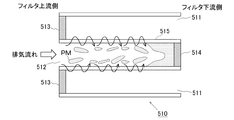
また、図5Bは、S104の処理によって、排気通路5における排気流れは順流のままで脈動の大きさが一時的に増大した場合の、フィルタ50aの隔壁515を通過する排気流れ、およびフィルタ50aにおけるPMの挙動の概念を示す図である。排気通路5における排気流れが順流のままでも脈動の大きさが増大すると、フィルタ50a内の排気流れに一時的な乱れが生じ、図5Bに示すように、隔壁515を通過する排気が順方向、逆方向の両方向に流れる。これは、その大きさが増大した脈動の影響により、第2通路512の圧力が第1通路511の圧力よりも大きくなる場合(この場合は、隔壁515を通過する排気が順方向に流れる。)と、第2通路512の圧力が第1通路511の圧力よりも小さくなる場合(この場合は、隔壁515を通過する排気が逆方向に流れる。)と、があるからである。そして、フィルタ50a内に一時的に生じた排気流れの乱れによって、隔壁515を通過する排気が逆方向に流れるときに、隔壁515からPMが剥離する。
FIG. 5B shows the exhaust flow passing through the
そして、S104の処理の後、S105において、全閉状態の排気シャット弁53を全開状態に制御する処理が実行される。その結果、局所的に逆流が生じていたフィルタ50a内の流れが順流に戻り、S104の処理によって剥離したPMが、フィルタの下流側部分に移動する。そして、S105の処理の後、本フローの実行が終了される。なお、S105の処理は、S104の処理によって隔壁515から剥離させたPMを、フィルタの下流側部分に移動させることができるタイミングで実行される。例えば、S105の処理は、S104の処理の後、所定期間経過後に実行されてもよいし、S104の処理により排気シャット弁53が全閉状態となった直後に実行されてもよい。
Then, after the process of S104, a process of controlling the fully closed exhaust shut-off
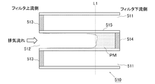
図5Cは、S105の処理によって、PMがフィルタの下流側部分に移動した状態を示す図である。ECU10が、上述したS101からS105の処理によって表される排気流れ制御を実行することによって、図5Cに示すように、PMがフィルタの下流側部分(破線で表される線L1よりも下流側)に集中して堆積する。
FIG. 5C is a diagram illustrating a state where PM has moved to the downstream portion of the filter by the process of S105. As shown in FIG. 5C, the
以上に述べた排気流れ制御によって、フィルタの下流側部分に集中してPMを堆積させることができる。そのため、該下流側の部分を昇温させることによって、フィルタ50a全体を昇温させる場合よりも、少ないエネルギで短時間にフィルタ50aの再生を行うことができる。そこで、ECU10は、電気加熱装置52を作動することによって、フィルタ50aを下流側から昇温させる。これにより、フィルタの下流側部分に集中して堆積したPMが酸化除去され、以て、フィルタ50aが再生される。なお、ECU10がこのようにフィルタ50aを再生する処理を実行することで、本発明に係る処理手段として機能する。
By the exhaust flow control described above, PM can be concentrated in the downstream portion of the filter. Therefore, by raising the temperature of the downstream portion, it is possible to regenerate the
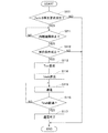
ここで、ECU10が実行するフィルタ50aの再生の制御フローについて図6に基づいて説明する。図6は、フィルタ50aを再生する処理の制御フローを示すフローチャートである。本実施例では、ECU10によって、本フローが内燃機関1の運転中に所定の演算周期で繰り返し実行される。
Here, the control flow of regeneration of the
本フローでは、先ず、S111において、フィルタ50aの再生要求が成立しているか否かが判別される。ここで、フィルタ50aの再生要求は、例えば、フィルタ50aに所定量以上のPMが堆積していると推定される場合に成立する。この場合、PM堆積量の推定が、本フローとは異なる周知のフローにしたがって実行される。そして、S111において肯定判定された場合、ECU10はS112の処理へ進み、S111において否定判定された場合、本フローの実行が終了される。
In this flow, first, in S111, it is determined whether or not a regeneration request for the
S111において肯定判定された場合、次に、S112において、フィルタ50aの再生を実行する実行条件が成立しているか否かが判別される。上述したように、電気加熱装置52は、フィルタ50aを下流側から昇温させる。したがって、仮にPMがフィルタの下流側部分に集中して堆積していない場合には、電気加熱装置52を作動させてもフィルタ50aからPMを十分に酸化除去することができない。そこで、ECU10は、PMがフィルタの下流側部分に集中して堆積しているか否かを推定する。そして、PMがフィルタの下流側部分に集中して堆積していると推定される場合には、S112において、フィルタ50aの再生を実行する実行条件が成立していると判別される。例えば、前回フィルタ50aの再生を行ってから現在までに排気流れ制御が実行されていれば、該排気流れ制御によってPMがフィルタの下流側部分に集中して堆積するため、フィルタ50aの再生を実行する実行条件が成立しているとして、S112において肯定判定される。そして、S112において肯定判定された場合、ECU10はS113の処理へ進み、S112において否定判定された場合、本フローの実行が終了される。
If an affirmative determination is made in S111, it is then determined in S112 whether or not an execution condition for executing the regeneration of the
S112において肯定判定された場合、次に、S113において、フィルタ後端側温度Tcrrが算出される。フィルタ後端側温度Tcrrは、フィルタの下流側部分の推定温度を表していて、第一温度センサ55の出力値に基づいて算出される。詳しくは、ECU10のROMには、フィルタ後端側温度Tcrrと第一温度センサ55の出力値との相関がマップまたは関数として予め記憶されていて、S113では、該マップまたは関数と、第一温度センサ55の出力値と、に基づいて、フィルタ後端側温度Tcrrが算出される。
If an affirmative determination is made in S112, next, the filter rear end side temperature Tcrr is calculated in S113. The filter rear end side temperature Tcrr represents the estimated temperature of the downstream portion of the filter and is calculated based on the output value of the
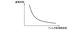
次に、S114において、電気加熱装置52への通電時間Tmehが算出される。ここで、通電時間Tmehは、PMがフィルタの下流側部分に集中して堆積していることを前提として、そのような状態でPMを酸化除去することが可能な電気加熱装置52への通電時間として定義される。なお、フィルタ50aにおけるPMの堆積密度が高い場合においては、PMの堆積密度が低い場合よりも、フィルタ50aの再生時にPMが連続的に延焼する傾向があるため、上記のように定義される通電時間Tmehは比較的短くなる。また、フィルタ50aにおいて、その温度が所定温度(例えば、600℃)以上となった部分で捕集されたPMが燃焼し始める。したがって、フィルタの下流側部分の温度を所定温度以上にすることができるような電気加熱装置52の作動時間として、通電時間Tmehが算出される。ここで、フィルタ後端側温度Tcrrと通電時間Tmehとの相関を図7に示す。図7に示すように、フィルタ後端側温度Tcrrが高いほど通電時間Tmehが短くされる。S114では、S113で算出したフィルタ後端側温度Tcrrと、ECU10のROMに記憶されたマップまたは関数であって、フィルタ後端側温度Tcrrと通電時間Tmehとの相関を表すマップまたは関数と、に基づいて、通電時間Tmehが算出される。
Next, in S114, the energization time Tmeh to the
次に、S115において、電気加熱装置52への通電が開始される。これにより、電気加熱装置52の作動が開始され、フィルタ50aが下流側から昇温される。そして、S116において、電気加熱装置52への通電が開始されてから通電時間Tmehが経過したか否かが判別される。S116において肯定判定された場合、この場合はフィルタの下流側部分の温度が所定温度以上となっていると推定される場合であって、ECU10はS1
17の処理へ進む。なお、フィルタの下流側部分の温度が所定温度以上となると、当該部分に堆積したPMが燃焼し始める。そして、PMが連続的に延焼する。その結果、フィルタ50aからPMが酸化除去される。一方、S116において否定判定された場合、ECU10はS115の処理へ戻り、S115において、電気加熱装置52への通電が継続される。
Next, in S115, energization of the
It progresses to the process of 17. In addition, when the temperature of the downstream part of a filter becomes more than predetermined temperature, PM deposited on the said part will start burning. And PM spreads fire continuously. As a result, PM is oxidized and removed from the
S116において肯定判定された場合、次に、S117において、電気加熱装置52への通電が終了される。そして、S117の処理の後、本フローの実行が終了される。なお、ECU10は、S117の処理の後、更に、フィルタ後端側温度Tcrrを算出してもよい。これにより、フィルタの下流側部分の温度が十分上昇していることを確認することができる。ここで、仮にフィルタ後端側温度Tcrrが所定の下限温度よりも低くなっている場合には、フィルタの下流側部分の温度が、何らかの理由でPMが酸化除去され得る所定温度に達していないとして、ECU10は、電気加熱装置52への通電を再開することができる。
If an affirmative determination is made in S116, energization to the
以上に述べたように、ECU10が、排気流れ制御を実行することによってPMをフィルタの下流側部分に移動させ、更に、電気加熱装置52を用いて該下流側部分を昇温させることによって、少ないエネルギで短時間にフィルタ50aの再生を行うことができる。つまり、本発明に係る内燃機関の排気浄化装置は、フィルタ50aに堆積したPMを好適に酸化除去することを可能とする。
As described above, the
<実施例2>
次に、本発明の第2の実施例について説明する。図8は、本実施例に係る内燃機関とその吸排気系の概略構成を示す図である。図8に示す内燃機関1は、軽油を燃料とする圧縮着火式の内燃機関(ディーゼルエンジン)である。ただし、本発明は、ガソリン等を燃料とする火花点火式の内燃機関にも適用することができる。なお、本実施例において、上述した実施例1と実質的に同一の構成、実質的に同一の制御処理については、その詳細な説明を省略する。
<Example 2>
Next, a second embodiment of the present invention will be described. FIG. 8 is a diagram showing a schematic configuration of the internal combustion engine and its intake / exhaust system according to the present embodiment. An
内燃機関1の排気通路5には排気の流れに従って順に、尿素水添加弁54、フィルタケース50、第一温度センサ55、NOxセンサ56、および排気シャット弁53が設けられている。フィルタケース50は、略筒状のケース内にSCRフィルタ50bを収容している。また、フィルタケース50は、SCRフィルタ50bよりも下流側に電気加熱装置52を収容している。SCRフィルタ50bは、多孔質の基材により形成されたウォールフロー型のフィルタに、SCR触媒51aが担持されて構成されている。ここで、フィルタは、排気中のPMを捕集する機能を有する。また、SCR触媒51aは、アンモニアを還元剤として排気中のNOxを還元する機能を有する。そのため、SCRフィルタ50bは、PM捕集機能およびNOx浄化機能を有している。ここで、本実施例では、図8に示すように、SCR触媒51aが、SCRフィルタ50bにおいて排気流れ方向における上流側の部分に担持されている。このようにSCR触媒51aが担持される部分は、少なくとも上記の図5Cに示した破線で表される線L1(上述したように、線L1よりも下流側にPMが集中して堆積している。)よりも上流側であって、PMの燃焼に伴って発生する熱のSCR触媒51aへの伝熱がある程度緩和されるように、線L1よりもある程度離れた上流側であることが好ましい。
In the
このような排気浄化装置においても、ECU10は、上述した実施例1と同様にして排気流れ制御を実行する。そして、ECU10が排気流れ制御を実行すると、SCRフィルタ50bに堆積したPMが該SCRフィルタ50bの下流側部分に移動し、PMが該下流側部分に集中して堆積することになる。
Also in such an exhaust purification device, the
そして、ECU10は、上述した実施例1と同様にしてSCRフィルタ50bの再生を行う。詳しくは、電気加熱装置52を用いてSCRフィルタ50bの下流側部分を昇温させることによって、該下流側部分に集中して堆積したPMを酸化除去する。これにより、少ないエネルギで短時間にSCRフィルタ50bの再生を行うことができる。
Then, the
ここで、本実施例において、PMの酸化除去の際に、SCR触媒51aが担持されたSCRフィルタ50bにおける上流側の部分は下流側の部分よりも温度が低くなる傾向にある。つまり、PMの酸化除去の際に、SCR触媒51aが、該SCR触媒51aが劣化し得る温度に曝される事態が生じ難くなる。その結果、SCRフィルタ50bの再生に伴うSCR触媒51aの劣化が抑制される。このように、本実施例の構成においても、本発明に係る内燃機関の排気浄化装置は、SCRフィルタ50bに堆積したPMを好適に酸化除去することを可能とする。
Here, in this embodiment, when the PM is removed by oxidation, the temperature of the upstream portion of the
また、ECU10は、内燃機関1の運転中に排気流れ制御を実行し、その後、内燃機関1が停止したときにSCRフィルタ50bの再生を行ってもよい。なお、内燃機関1の運転中とは、イグニッションオフされていない状態を表し、上述した燃料カット処理の実行は、内燃機関1の運転中に含まれるものとする。ECU10が実行するこのようなSCRフィルタ50bの再生の制御フローについて、図9に基づいて説明する。図9は、SCRフィルタ50bを再生する処理の制御フローを示すフローチャートである。
Further, the
図9に示すフローでは、上記の図6に示したフローと同様に、S111において、フィルタ50aの再生要求が成立しているか否かが判別される。このS111の処理は、内燃機関1の運転中に所定の演算周期で繰り返し実行される。そして、S111において肯定判定された場合、次に、S211において、内燃機関1が停止したか否かが判別される。そして、S211において肯定判定された場合、ECU10はS112の処理へ進み、S211において否定判定された場合、ECU10はS211の処理を所定の周期で繰り返す。なお、ECU10がS211の処理を所定の周期で繰り返している間は、本フローの次回の実行タイミングが訪れても、ECU10はS211の処理を優先して継続する。
In the flow shown in FIG. 9, as in the flow shown in FIG. 6, it is determined in S111 whether or not the regeneration request for the
このように図9に示すフローでは、SCRフィルタ50bの再生が内燃機関1の停止中に行われる。ここで、尿素水添加弁54からの尿素水は高温で酸化しNOx化する傾向にあるものの、内燃機関1の停止中には尿素水添加弁54から尿素水が供給されないため、SCRフィルタ50bの再生が内燃機関1の停止中に行われる場合には、尿素水のNOx化が抑制される。つまり、内燃機関1の停止中にSCRフィルタ50bの再生を行うことによって、当該再生の処理がSCR触媒51aによるNOx浄化に影響を及ぼしてしまうことを排除することができる。
As described above, in the flow shown in FIG. 9, the regeneration of the
[実施例2の変形例]
次に、上述した実施例2の変形例について説明する。図10は、本変形例に係る内燃機関とその吸排気系の概略構成を示す図である。なお、本変形例において、上述した実施例2と実質的に同一の構成、実質的に同一の制御処理については、その詳細な説明を省略する。
[Modification of Example 2]
Next, a modification of the above-described second embodiment will be described. FIG. 10 is a diagram showing a schematic configuration of an internal combustion engine and its intake / exhaust system according to this modification. In the present modification, detailed description of the substantially same configuration and substantially the same control processing as those in the second embodiment will be omitted.
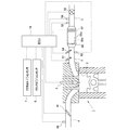
本変形例に係る内燃機関1の排気通路5には、フィルタケース50よりも上流側に、尿素水添加弁54に加えて、エア供給弁61および第二温度センサ62が設けられる。エア供給弁61は、図示しないポンプに接続されていて、排気通路5内にエアを供給する。ここで、エア供給弁61においては、内燃機関1が停止していてもSCRフィルタ50bに上流側から下流側へのエアの流れを生じさせることができるように、その配置が定められ、また、該エア供給弁61からのエアの供給量や供給圧力等が定められる。
In the
このような排気浄化装置においても、ECU10は、上述した実施例1と同様にして排気流れ制御を実行する。そして、ECU10が排気流れ制御を実行すると、SCRフィルタ50bに堆積したPMが該SCRフィルタ50bの下流側部分に移動し、PMが該下流側部分に集中して堆積することになる。
Also in such an exhaust purification device, the
そして、ECU10は、上述した実施例2と同様に、内燃機関1の停止中にSCRフィルタ50bの再生を行うこともできる。ここで、SCRフィルタ50bの再生においては、該SCRフィルタ50bが過昇温してしまう事態が生じ得る。そして、仮に内燃機関1の停止中にSCRフィルタ50bが過昇温してしまった場合には、該SCRフィルタ50bを速やかに冷却し難くなる。そこで、ECU10は、内燃機関1の停止中におけるSCRフィルタ50bの再生に伴って、該SCRフィルタ50bが過昇温してしまう虞がある場合には、エア供給弁61を用いて該SCRフィルタ50bに上流側から下流側へのエアの流れを生じさせる。ここで、ECU10は、SCRフィルタ50bを速やかに冷却することができるように、エア供給弁61からのエアの供給量や供給圧力等を設定する。これにより、内燃機関1の停止中にSCRフィルタ50bの再生を行う場合において、好適にSCRフィルタ50bの過昇温を抑制することができる。
The
また、上記の図9に示したフローにおいて、ECU10は、SCRフィルタ50bの下流側部分の温度が十分上昇していることを確認するために、S117の処理の後、更に、フィルタ後端側温度Tcrrを算出してもよいが、内燃機関1の停止中には排気の流れがないため、フィルタ後端側温度Tcrrが正確に算出されない虞がある。そこで、ECU10は、S117の処理の後にフィルタ後端側温度Tcrrを算出する際に、エア供給弁61を用いてSCRフィルタ50bに上流側から下流側へのエアの流れを生じさせてもよい。なお、この場合、エア供給弁61からSCRフィルタ50bに供給されるエアの温度が第二温度センサ62によって検出される。そして、第二温度センサ62によって検出されるSCRフィルタ50bに流入するエアの温度と、第一温度センサ55によって検出されるSCRフィルタ50bから流出するエアの温度と、ECU10のROMに記憶されたマップまたは関数であって、これら温度とフィルタ後端側温度Tcrrとの相関を表すマップまたは関数と、に基づいて、フィルタ後端側温度Tcrrを算出することができる。
Further, in the flow shown in FIG. 9, the
1・・・内燃機関
4・・・吸気通路
5・・・排気通路
10・・ECU
40・・エアフローメータ
50・・フィルタケース
50a・フィルタ
50b・SCRフィルタ
51・・触媒ケース
51a・SCR触媒
52・・電気加熱装置
53・・排気シャット弁
54・・尿素水添加弁
55・・第一温度センサ
56・・NOxセンサ
510・基材
511・第1通路
512・第2通路
515・隔壁
DESCRIPTION OF
40 ··
Claims (3)
前記フィルタを排気流れ方向における下流側から昇温させる昇温手段と、
前記フィルタよりも下流の前記排気通路に設けられ、全開、全閉を切替えて弁を開閉するように構成されている排気シャット弁と、
排気流量が所定流量以上である場合に、前記排気シャット弁を一旦全閉にした後全開にすることで前記フィルタにおける排気流れを制御し、該フィルタに堆積した粒子状物質を該フィルタにおいて排気流れ方向における下流側の部分に移動させる制御手段と、
前記制御手段が粒子状物質を前記下流側の部分に移動させた後において、前記昇温手段を用いて前記フィルタに堆積した粒子状物質を酸化除去する処理である再生処理を実行する処理手段と、
を備える、内燃機関の排気浄化装置。 A filter provided in an exhaust passage of an internal combustion engine, having a plurality of cells partitioned by partition walls along an exhaust flow direction, wherein the downstream end in the exhaust flow direction is blocked in the plurality of cells, and A wall flow type filter in which cells whose upstream ends are open and cells whose upstream ends in the exhaust flow direction are closed and whose downstream ends are open are alternately arranged;
A temperature raising means for raising the temperature of the filter from the downstream side in the exhaust flow direction;
An exhaust shut valve provided in the exhaust passage downstream of the filter and configured to open and close the valve by switching between full open and full close;
When the exhaust flow rate is equal to or higher than a predetermined flow rate, the exhaust shut-off valve is temporarily closed and then fully opened to control the exhaust flow in the filter, and the particulate matter deposited on the filter is exhausted in the filter. Control means for moving to the downstream part in the direction;
Processing means for performing regeneration processing, which is processing for oxidizing and removing particulate matter deposited on the filter using the temperature raising means after the control means moves the particulate matter to the downstream portion; ,
An exhaust purification device for an internal combustion engine, comprising:
請求項1に記載の内燃機関の排気浄化装置。 The filter is an SCR filter in which a selective reduction type NOx catalyst is carried on the partition wall, and the selective reduction type NOx catalyst is carried on the upstream side of a predetermined portion on the downstream side in the exhaust flow direction in the filter. It is characterized by
The exhaust emission control device for an internal combustion engine according to claim 1.
請求項2に記載の内燃機関の排気浄化装置。 The processing means performs the regeneration process while the internal combustion engine is stopped.
The exhaust emission control device for an internal combustion engine according to claim 2.
Priority Applications (4)
| Application Number | Priority Date | Filing Date | Title |
|---|---|---|---|
| JP2017017354A JP2018123776A (en) | 2017-02-02 | 2017-02-02 | Exhaust gas purification device for internal combustion engine |
| CN201711453053.9A CN108386255A (en) | 2017-02-02 | 2017-12-28 | The emission-control equipment of internal combustion engine |
| US15/860,982 US10344645B2 (en) | 2017-02-02 | 2018-01-03 | Exhaust gas purification apparatus for internal combustion engine |
| DE102018102239.5A DE102018102239A1 (en) | 2017-02-02 | 2018-02-01 | Exhaust gas purification device for internal combustion engine |
Applications Claiming Priority (1)
| Application Number | Priority Date | Filing Date | Title |
|---|---|---|---|
| JP2017017354A JP2018123776A (en) | 2017-02-02 | 2017-02-02 | Exhaust gas purification device for internal combustion engine |
Publications (1)
| Publication Number | Publication Date |
|---|---|
| JP2018123776A true JP2018123776A (en) | 2018-08-09 |
Family
ID=62843289
Family Applications (1)
| Application Number | Title | Priority Date | Filing Date |
|---|---|---|---|
| JP2017017354A Pending JP2018123776A (en) | 2017-02-02 | 2017-02-02 | Exhaust gas purification device for internal combustion engine |
Country Status (4)
| Country | Link |
|---|---|
| US (1) | US10344645B2 (en) |
| JP (1) | JP2018123776A (en) |
| CN (1) | CN108386255A (en) |
| DE (1) | DE102018102239A1 (en) |
Cited By (1)
| Publication number | Priority date | Publication date | Assignee | Title |
|---|---|---|---|---|
| JP2025063746A (en) * | 2023-10-04 | 2025-04-16 | 井関農機株式会社 | Work vehicles |
Families Citing this family (3)
| Publication number | Priority date | Publication date | Assignee | Title |
|---|---|---|---|---|
| EP4063627B1 (en) | 2021-03-25 | 2024-12-11 | Volvo Truck Corporation | An exhaust aftertreatment arrangement for converting nox emissions |
| EP4063625B1 (en) * | 2021-03-25 | 2024-11-13 | Volvo Truck Corporation | An exhaust aftertreatment unit for cleaning exhaust gases |
| EP4283099B1 (en) * | 2022-05-25 | 2025-01-29 | Volvo Truck Corporation | An exhaust aftertreatment system (eats) |
Citations (7)
| Publication number | Priority date | Publication date | Assignee | Title |
|---|---|---|---|---|
| JPH0544436A (en) * | 1991-08-09 | 1993-02-23 | Nissan Motor Co Ltd | Exhaust gas purifying device for internal combustion engine |
| JPH07279647A (en) * | 1994-04-14 | 1995-10-27 | Nippondenso Co Ltd | Cylindrical honeycomb filter |
| WO2001073273A1 (en) * | 2000-03-29 | 2001-10-04 | Toyota Jidosha Kabushiki Kaisha | Exhaust gas cleaning device for internal combustion engines |
| WO2006028163A1 (en) * | 2004-09-09 | 2006-03-16 | Hino Motors, Ltd. | Exhaust gas purification device |
| JP2008115775A (en) * | 2006-11-06 | 2008-05-22 | Toyota Motor Corp | Exhaust gas purification system for internal combustion engine |
| US20140060008A1 (en) * | 2012-09-06 | 2014-03-06 | Daimler Ag | Method for Operating a Motor Vehicle Internal Combustion Engine with an Exhaust Particle Filter |
| JP2014227938A (en) * | 2013-05-23 | 2014-12-08 | トヨタ自動車株式会社 | Internal combustion engine exhaust emission control device |
Family Cites Families (8)
| Publication number | Priority date | Publication date | Assignee | Title |
|---|---|---|---|---|
| US4875336A (en) * | 1988-01-12 | 1989-10-24 | Toyota Jidosha Kabushiki Kaisha | Exhaust gas emission control device for diesel engine |
| JP3395533B2 (en) * | 1996-08-09 | 2003-04-14 | トヨタ自動車株式会社 | Diesel engine exhaust purification system |
| US7992382B2 (en) * | 2003-08-01 | 2011-08-09 | Illinois Valley Holding Company | Particulate trap system and method |
| US7384455B2 (en) * | 2004-10-05 | 2008-06-10 | Caterpillar Inc. | Filter service system and method |
| JP2006183507A (en) | 2004-12-27 | 2006-07-13 | Mitsubishi Fuso Truck & Bus Corp | Exhaust emission control device for internal combustion engine |
| GB2429417B (en) * | 2005-08-25 | 2010-08-11 | Perkins Engines Co Ltd | Autoselective regenerating particulate filter |
| JP2010065554A (en) * | 2008-09-09 | 2010-03-25 | Nissan Diesel Motor Co Ltd | Exhaust emission control device of diesel engine |
| CN104389656A (en) * | 2014-09-26 | 2015-03-04 | 苏州博菡环保科技有限公司 | Diesel engine exhaust particle purifier |
-
2017
- 2017-02-02 JP JP2017017354A patent/JP2018123776A/en active Pending
- 2017-12-28 CN CN201711453053.9A patent/CN108386255A/en not_active Withdrawn
-
2018
- 2018-01-03 US US15/860,982 patent/US10344645B2/en not_active Expired - Fee Related
- 2018-02-01 DE DE102018102239.5A patent/DE102018102239A1/en not_active Withdrawn
Patent Citations (7)
| Publication number | Priority date | Publication date | Assignee | Title |
|---|---|---|---|---|
| JPH0544436A (en) * | 1991-08-09 | 1993-02-23 | Nissan Motor Co Ltd | Exhaust gas purifying device for internal combustion engine |
| JPH07279647A (en) * | 1994-04-14 | 1995-10-27 | Nippondenso Co Ltd | Cylindrical honeycomb filter |
| WO2001073273A1 (en) * | 2000-03-29 | 2001-10-04 | Toyota Jidosha Kabushiki Kaisha | Exhaust gas cleaning device for internal combustion engines |
| WO2006028163A1 (en) * | 2004-09-09 | 2006-03-16 | Hino Motors, Ltd. | Exhaust gas purification device |
| JP2008115775A (en) * | 2006-11-06 | 2008-05-22 | Toyota Motor Corp | Exhaust gas purification system for internal combustion engine |
| US20140060008A1 (en) * | 2012-09-06 | 2014-03-06 | Daimler Ag | Method for Operating a Motor Vehicle Internal Combustion Engine with an Exhaust Particle Filter |
| JP2014227938A (en) * | 2013-05-23 | 2014-12-08 | トヨタ自動車株式会社 | Internal combustion engine exhaust emission control device |
Cited By (1)
| Publication number | Priority date | Publication date | Assignee | Title |
|---|---|---|---|---|
| JP2025063746A (en) * | 2023-10-04 | 2025-04-16 | 井関農機株式会社 | Work vehicles |
Also Published As
| Publication number | Publication date |
|---|---|
| US10344645B2 (en) | 2019-07-09 |
| US20180216511A1 (en) | 2018-08-02 |
| CN108386255A (en) | 2018-08-10 |
| DE102018102239A1 (en) | 2018-08-02 |
Similar Documents
| Publication | Publication Date | Title |
|---|---|---|
| JP5644164B2 (en) | Exhaust gas purification device | |
| JP6051948B2 (en) | Exhaust gas purification device for internal combustion engine | |
| JP6614187B2 (en) | Exhaust gas purification device for internal combustion engine | |
| GB2555851A (en) | Treatment of engine exhaust gases | |
| CN108301900A (en) | The emission-control equipment of internal combustion engine and the exhaust gas-cleaning method of internal combustion engine | |
| EP2737192B1 (en) | Exhaust gas control apparatus for internal combustion engines, and control method for exhaust gas control apparatus for internal combustion engines | |
| JP2009002308A (en) | Exhaust purification device | |
| US9200555B2 (en) | Control device for electrically heated catalyst | |
| JP5830832B2 (en) | Filter regeneration device | |
| JP5251711B2 (en) | Exhaust gas purification device for internal combustion engine | |
| JP6436132B2 (en) | Exhaust gas purification system for internal combustion engine | |
| JP2018123776A (en) | Exhaust gas purification device for internal combustion engine | |
| JP2006342734A (en) | Exhaust emission control device | |
| JP2015094337A (en) | Exhaust gas purification system for internal combustion engine | |
| CN107208521B (en) | Exhaust gas purification system of internal combustion engine, internal combustion engine, and exhaust gas purification method of internal combustion engine | |
| JP4320586B2 (en) | Exhaust gas purification device for internal combustion engine | |
| JP2010249076A (en) | Exhaust gas purification device for internal combustion engine | |
| JP2020045889A (en) | Exhaust gas purification device | |
| WO2015129463A1 (en) | Exhaust purification apparatus for internal combustion engine | |
| JP4033189B2 (en) | Exhaust gas purification device for internal combustion engine | |
| JP4640145B2 (en) | Exhaust gas purification system for internal combustion engine | |
| JP2018044471A (en) | Exhaust emission control device and exhaust emission control method | |
| JP6682972B2 (en) | Exhaust gas purification device for internal combustion engine | |
| JP2015075011A (en) | Exhaust emission control device for internal combustion engine | |
| JP4411942B2 (en) | Exhaust gas purification device for internal combustion engine |
Legal Events
| Date | Code | Title | Description |
|---|---|---|---|
| A621 | Written request for application examination |
Free format text: JAPANESE INTERMEDIATE CODE: A621 Effective date: 20180827 |
|
| A977 | Report on retrieval |
Free format text: JAPANESE INTERMEDIATE CODE: A971007 Effective date: 20190515 |
|
| A131 | Notification of reasons for refusal |
Free format text: JAPANESE INTERMEDIATE CODE: A131 Effective date: 20190521 |
|
| A02 | Decision of refusal |
Free format text: JAPANESE INTERMEDIATE CODE: A02 Effective date: 20191119 |