JP2018123760A - Fuel tank - Google Patents
Fuel tank Download PDFInfo
- Publication number
- JP2018123760A JP2018123760A JP2017016610A JP2017016610A JP2018123760A JP 2018123760 A JP2018123760 A JP 2018123760A JP 2017016610 A JP2017016610 A JP 2017016610A JP 2017016610 A JP2017016610 A JP 2017016610A JP 2018123760 A JP2018123760 A JP 2018123760A
- Authority
- JP
- Japan
- Prior art keywords
- delivery pipe
- filter member
- fuel
- bent
- suction port
- Prior art date
- Legal status (The legal status is an assumption and is not a legal conclusion. Google has not performed a legal analysis and makes no representation as to the accuracy of the status listed.)
- Pending
Links
Images
Landscapes
- Cooling, Air Intake And Gas Exhaust, And Fuel Tank Arrangements In Propulsion Units (AREA)
Abstract
【課題】フィルタ部材の送出管への取り付け性を向上させる。【解決手段】燃料タンク1は、燃料を収容する収容部10と、収容部10内の燃料を吸い込む吸い込み口22を有し、吸い込んだ燃料をエンジンへ送出する送出管20と、吸い込み口22を囲むフィルタ部材40とを備える。送出管20は、屈曲している屈曲部24を有し、フィルタ部材40は、送出管20が挿通している挿通部45と、送出管20の屈曲部24から見て吸い込み口22とは反対側の部分に係止している係止部48とを有する。【選択図】図3An object of the present invention is to improve the attachment of a filter member to a delivery pipe. A fuel tank (1) has a storage part (10) for storing fuel, a suction port (22) for sucking fuel in the storage part (10), a delivery pipe (20) for sending the sucked fuel to the engine, and a suction port (22). And a surrounding filter member 40. The delivery pipe 20 has a bent part 24 that is bent, and the filter member 40 is opposite to the insertion part 45 through which the delivery pipe 20 is inserted and the suction port 22 when viewed from the bent part 24 of the delivery pipe 20. And a locking portion 48 that is locked to the side portion. [Selection] Figure 3
Description
本発明は、車両に搭載される燃料タンクに関する。 The present invention relates to a fuel tank mounted on a vehicle.
トラック等の車両には、エンジンに供給される燃料を貯留する燃料タンクが設けられている。
燃料タンクは、燃料を収容する収容部と、収容部に収容された燃料を吸い込んでエンジンへ送出する送出管と、送出管の吸い込み口に設けられ燃料中の異物が吸い込まれることを抑制するためのフィルタ部材とを有する。フィルタ部材は、送出管に着脱可能に装着されている。
A vehicle such as a truck is provided with a fuel tank for storing fuel supplied to the engine.
The fuel tank is provided with a storage portion for storing fuel, a delivery pipe for sucking the fuel contained in the accommodation portion and sending it to the engine, and a suction port of the delivery pipe for suppressing foreign matter in the fuel from being sucked in. And a filter member. The filter member is detachably attached to the delivery pipe.
ところで、フィルタ部材として、外周面に多数の孔が形成された円筒状の金属部材が用いられている。このようなフィルタ部材を送出管に装着する場合には、フィルタ部材と送出管の間にガスケット等を介在してネジ等の締結部材で固定するため、作業者が行う工数が多くなり、作業性が悪い。 By the way, a cylindrical metal member having a large number of holes formed on the outer peripheral surface is used as the filter member. When such a filter member is attached to the delivery pipe, a gasket or the like is interposed between the filter member and the delivery pipe and fixed with a fastening member such as a screw. Is bad.
そこで、本発明はこれらの点に鑑みてなされたものであり、フィルタ部材の送出管への取り付け性を向上させることを目的とする。 Therefore, the present invention has been made in view of these points, and an object thereof is to improve the attachment property of the filter member to the delivery pipe.
本発明の一の態様においては、燃料を収容する収容部と、前記収容部内の前記燃料を吸い込む吸い込み口を有し、吸い込んだ前記燃料をエンジンへ送出する送出管と、前記吸い込み口を囲むフィルタ部材と、を備え、前記送出管は、屈曲している屈曲部を有し、前記フィルタ部材は、前記送出管が挿通している挿通部と、前記送出管の前記屈曲部から見て前記吸い込み口とは反対側の部分に係止している係止部と、を有する、燃料タンクを提供する。
かかる燃料タンクによれば、フィルタ部材を送出管に取り付ける際に、送出管が挿通部を通過した後に係止部が屈曲部の上方に係止されることで、ネジ等の締結部材を用いなくても、フィルタ部材が送出管に固定される。これにより、フィルタ部材の送出管への取り付け性を向上できる。
In one aspect of the present invention, the fuel cell has a housing portion that houses fuel, a suction port that sucks the fuel in the housing portion, a delivery pipe that delivers the sucked fuel to the engine, and a filter that surrounds the suction port A member, and the delivery pipe has a bent portion that is bent, and the filter member is inserted through the delivery pipe and the suction portion as viewed from the bent portion of the delivery pipe. There is provided a fuel tank having a locking portion locked to a portion opposite to the mouth.
According to such a fuel tank, when the filter member is attached to the delivery pipe, the fastening part is latched above the bent part after the delivery pipe passes through the insertion part, so that a fastening member such as a screw is not used. Even so, the filter member is secured to the delivery tube. Thereby, the attachment property to the delivery pipe of a filter member can be improved.
また、前記フィルタ部材は、前記送出管を囲む円筒状の本体部を更に有し、前記係止部は、前記本体部から軸方向に延出していることとしてもよい。 The filter member may further include a cylindrical main body that surrounds the delivery pipe, and the locking portion may extend in the axial direction from the main body.
また、前記フィルタ部材は、前記挿通部から軸方向に沿って延出した円筒部を更に有することとしてもよい。 Moreover, the said filter member is good also as having further the cylindrical part extended along the axial direction from the said insertion part.
また、前記屈曲部は、前記挿通部の軸方向と成す角度が鈍角になるように、屈曲していることとしてもよい。 The bent portion may be bent such that an angle formed with the axial direction of the insertion portion is an obtuse angle.
本発明によれば、フィルタ部材の送出管への取り付け性を向上できるという効果を奏する。 According to the present invention, it is possible to improve the attachment property of the filter member to the delivery pipe.
<燃料タンクの構成>
図1及び図2を参照しながら、本発明の一の実施形態に係る燃料タンク1の構成について説明する。
<Configuration of fuel tank>
The configuration of the
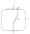
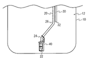
図1は、一の実施形態に係る燃料タンク1の外観構成の一例を説明するための図である。図2は、燃料タンク1の内部構成の一例を説明するための図である。なお、図1では、燃料タンク1内の送出管20を破線で示している。
Drawing 1 is a figure for explaining an example of the appearance composition of
燃料タンク1は、車両の一例であるトラックに搭載されている。燃料タンク1は、車両のエンジン(不図示)に供給される燃料を貯留する。燃料タンク1は、図1及び図2に示すように、収容部10と、送出管20と、戻り管30と、大気開放バルブ35と、フィルタ部材40とを有する。
The
収容部10は、燃料を収容する。収容部10は、箱状の形状を成しており、内部に燃料を収容する空間12を有する。収容部10内の燃料は、給油口から適宜給油される。収容部10は、ここでは軽油を収容するが、これに限定されず、例えばガソリンを収容してもよい。
The accommodating part 10 accommodates fuel. The accommodating part 10 has a box shape and has a
送出管20は、収容部10内の燃料を吸い込んで、エンジンへ送出するフィードパイプである。送出管20は、先端に、燃料を吸い込む吸い込み口22を有する。送出管20は、戻り管30と共に、収容部10の上部に固定されている。なお、送出管20は、収容部10とエンジンとの間に配置されており、途中には燃料を吸い込むためのポンプ(不図示)が設けられている。
The
送出管20は、図1に示すように、収容部10内で屈曲している。具体的には、送出管20は、吸い込み口22が収容部10の下方の中央に位置するように、屈曲している。例えば、送出管20は、2つの屈曲部24、26を有する。これにより、例えば車両の走行中に収容部10内で燃料の水位が斜めになっても、燃料が吸い込み口22から吸い込まれやすくなる。
As shown in FIG. 1, the
戻り管30は、エンジンで消費されなかった燃料を、収容部10内へ戻すリターンパイプである。戻り管30は、エンジンから戻った燃料が収容部10内へ落下する開口32を有する。なお、戻り管30から収容部10内へ落下する燃料は、エンジンを通過しているため、エンジンへ供給される時よりも温度が高くなっている。
The
大気開放バルブ35は、収容部10内を大気圧と同等にするため空気を内部へ取り込んだり、外部へ放出するためのバルブである。収容部10内へ空気を取り込むことでポンプの燃料吸い込みにより収容部10内が負圧化することを防ぎ燃料の吸い込みが円滑に行われるようになる。
The
フィルタ部材40は、燃料中の異物が吸い込み口22から吸い込まれることを抑制する機能を有する。異物としては、例えば低温時に燃料の水分が氷結した氷結物や、ゴミ等が挙げられる。
The
フィルタ部材40は、図2に示すように送出管20の先端部に取り付けられている。具体的には、フィルタ部材40は、円筒状の部材であり、送出管20において吸い込み口22の周囲に取り付けられている。また、フィルタ部材40は、ネジ等の締結部材を介さずに、送出管20の屈曲部24の上方に固定されている。
The
<フィルタ部材の詳細構成>
図3及び図4を参照しながら、フィルタ部材40の詳細構成について説明する。
<Detailed configuration of filter member>
A detailed configuration of the
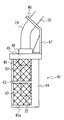
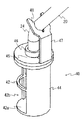
図3は、フィルタ部材40の構成の一例を説明するための図である。図4は、フィルタ部材40の送出管20に対する固定状態の一例を説明するための図である。なお、図4では、説明の便宜上、図3に示すメッシュ50が省略されている。
FIG. 3 is a diagram for explaining an example of the configuration of the
フィルタ部材40は、樹脂製である。フィルタ部材40は、図3及び図4に示すように、本体部42と、遮蔽壁44と、挿通部45と、円筒部46と、延出部47と、係止部48とを有する。
The
本体部42は、図4に示すように円筒状に形成されている。すなわち、本体部42は、送出管20(具体的には、吸い込み口22)を囲むように位置している。本体部42の底面42aは、吸い込み口22と所定距離だけ離れて対向している。
The
本体部42には、図4に示すように、周方向に沿った開口42bが形成されている。開口42bには、メッシュ50(図3)が設けられている。メッシュ50は、網目状に形成されており、燃料中の異物の通過を阻止している。例えば、メッシュ50は、低温時の水分の氷結物の通過を阻止している。
As shown in FIG. 4, an opening 42 b is formed in the
遮蔽壁44は、本体部42においてメッシュ50が設けられていない部分であり、戻り管30からの燃料の落下点に面する側の円弧状の壁である(図2参照)。遮蔽壁44は、燃料の落下点と吸い込み口22との間に位置し、戻り管30から落下した燃料の吸い込み口22への移動を規制する規制部としての機能を有する。遮蔽壁44にメッシュ50が設けられていないので、遮蔽壁44は、戻り管30から落下した燃料の吸い込み口22への移動を遮蔽する。
The shielding
挿通部45は、送出管20が挿通する部分である。挿通部45には、送出管20が挿通可能な貫通孔(不図示)が形成されている。フィルタ部材40を送出管20に取り付ける際には、送出管20の吸い込み口22側から挿通部45を挿通させる。なお、フィルタ部材40をスムーズに取り付けられるように、挿通部45の貫通孔の直径は、送出管20の外径よりも大きくなっている。
The
円筒部46は、挿通部45から軸方向に沿って延出している円筒状の部分である。円筒部46は、図3に示すように、軸方向において挿通部45の両側に形成されている。円筒部46を設けることによって、フィルタ部材40の送出管20の半径方向への移動を規制できる。
The
延出部47は、図4に示すように、本体部42から軸方向に延出している部分である。延出部47は、円筒部46から垂直に上方へ延出している。
As shown in FIG. 4, the extending
係止部48は、図4に示すように、延出部47の先端側に設けられており、送出管20に係止している部分である。係止部48は、送出管20の屈曲部24から見て吸い込み口22とは反対側の部分(屈曲部24の上方の部分)に係止している。係止部48の先端は、送出管20に引っ掛かっている。なお、係止部48が送出管20に引っ掛かっている際には、送出管20の引っ掛かっている部分に対して係止部48が垂直になっている。これにより、簡易な構成で、フィルタ部材40を送出管20に固定できる。
As shown in FIG. 4, the locking
ところで、送出管20の屈曲部24は、円筒状のフィルタ部材40の軸方向と成す角度が鈍角となるように、屈曲している。かかる場合には、上述した挿通部45及び円筒部46がフィルタ部材40の半径方向への移動を規制するために、フィルタ部材40が送出管20に沿って斜め上方へ移動し難い。この結果、送出管20に固定されたフィルタ部材40の位置ずれ(具体的には、フィルタ部材40の底面42aと吸い込み口22との間の距離が変動すること)を抑制できるので、送出管20による燃料の吸い込みを適切に行える。
By the way, the
<フィルタ部材の取り付け例>
図5〜図7を参照しながら、フィルタ部材40の送出管20への取り付け例について説明する。
<Example of filter member installation>
An example of attaching the
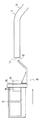
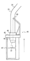
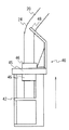
図5は、取り付け前のフィルタ部材40及び送出管20の状態を示す図である。図6及び図7は、フィルタ部材40の取り付け中の状態を示す図である。なお、図5〜図7では、説明の便宜上、メッシュ50(図3)が省略されている。
FIG. 5 is a view showing a state of the
ここでは、フィルタ部材40が図5に示すように送出管20から離れているものとして説明する。まず、作業者は、フィルタ部材40を送出管20の軸方向と平行にした状態で、図5に示す矢印方向に移動させる。
Here, description will be made assuming that the
これにより、図6に示すように、フィルタ部材40の挿通部45に対して送出管20が挿通することになる。なお、挿通部45の貫通孔に対して送出管20が挿通を開始する前に、係止部48が送出管20に接する。しかし、係止部48は、図4に示す固定状態とは異なり、送出管20に係止されずに、係止部48の先端(エッジ)が送出管20に接触した状態で挿通が継続される(図7参照)。係止部48の先端の移動の軌跡が、図6の一点鎖線で示されている。
As a result, as shown in FIG. 6, the
その後、係止部48が、送出管20の屈曲部24を乗り越えて図4に示す位置になるまで、フィルタ部材40を移動させると、係止部48が送出管20に引っ掛かって係止される。このように、フィルタ部材40を移動させるだけで、係止部48が自然に送出管20に引っ掛かるので、作業性が向上する。
Thereafter, when the
<本実施形態における効果>
上述した実施形態によれば、図3に示すように、送出管20は、吸い込み口22側で屈曲している屈曲部24を有する。また、吸い込み口22を囲むフィルタ部材40は、送出管20が挿通している挿通部45と、送出管20の屈曲部24から見て吸い込み口22とは反対側の部分に係止している係止部48と、を有する。
上記の構成により、フィルタ部材40を送出管20に取り付ける際に、送出管20が挿通部45を通過した後に係止部48が屈曲部24の上方に係止されることで、ネジ等の締結部材を用いなくても、フィルタ部材40が送出管20に固定される。これにより、フィルタ部材40の送出管20への取り付け性を向上できる。
また、フィルタ部材40に挿通部45及び円筒部46を設けたことで、取り付け後のフィルタ部材40の送出管20に対する位置ずれを抑制できるので、送出管20による燃料の吸い込みを適切に行える。
<Effect in this embodiment>
According to the embodiment described above, as shown in FIG. 3, the
With the above configuration, when the
In addition, since the
以上、本発明を実施の形態を用いて説明したが、本発明の技術的範囲は上記実施の形態に記載の範囲には限定されない。上記実施の形態に、多様な変更又は改良を加えることが可能であることが当業者に明らかである。そのような変更又は改良を加えた形態も本発明の技術的範囲に含まれ得ることが、特許請求の範囲の記載から明らかである。 As mentioned above, although this invention was demonstrated using embodiment, the technical scope of this invention is not limited to the range as described in the said embodiment. It will be apparent to those skilled in the art that various modifications or improvements can be added to the above embodiment. It is apparent from the scope of the claims that the embodiments added with such changes or improvements can be included in the technical scope of the present invention.
1 燃料タンク
10 収容部
20 送出管
22 吸い込み口
24 屈曲部
40 フィルタ部材
42 本体部
45 挿通部
46 円筒部
48 係止部
DESCRIPTION OF
Claims (4)
前記収容部内の前記燃料を吸い込む吸い込み口を有し、吸い込んだ前記燃料をエンジンへ送出する送出管と、
前記吸い込み口を囲むフィルタ部材と、
を備え、
前記送出管は、屈曲している屈曲部を有し、
前記フィルタ部材は、
前記送出管が挿通している挿通部と、
前記送出管の前記屈曲部から見て前記吸い込み口とは反対側の部分に係止している係止部と、を有する、燃料タンク。 A storage section for storing fuel;
A delivery pipe for sucking the fuel in the housing portion and delivering the sucked fuel to the engine;
A filter member surrounding the suction port;
With
The delivery tube has a bent portion that is bent;
The filter member is
An insertion portion through which the delivery pipe is inserted;
A fuel tank, comprising: a locking portion locked to a portion opposite to the suction port as viewed from the bent portion of the delivery pipe.
前記係止部は、前記本体部から軸方向に延出している、
請求項1に記載の燃料タンク。 The filter member further includes a cylindrical main body portion surrounding the delivery pipe,
The locking portion extends in the axial direction from the main body portion,
The fuel tank according to claim 1.
請求項1又は2に記載の燃料タンク。 The filter member further includes a cylindrical portion extending along the axial direction from the insertion portion.
The fuel tank according to claim 1 or 2.
請求項1から3のいずれか1項に記載の燃料タンク。
The bent portion is bent such that an angle formed with the axial direction of the insertion portion is an obtuse angle.
The fuel tank according to any one of claims 1 to 3.
Priority Applications (1)
| Application Number | Priority Date | Filing Date | Title |
|---|---|---|---|
| JP2017016610A JP2018123760A (en) | 2017-02-01 | 2017-02-01 | Fuel tank |
Applications Claiming Priority (1)
| Application Number | Priority Date | Filing Date | Title |
|---|---|---|---|
| JP2017016610A JP2018123760A (en) | 2017-02-01 | 2017-02-01 | Fuel tank |
Publications (1)
| Publication Number | Publication Date |
|---|---|
| JP2018123760A true JP2018123760A (en) | 2018-08-09 |
Family
ID=63110214
Family Applications (1)
| Application Number | Title | Priority Date | Filing Date |
|---|---|---|---|
| JP2017016610A Pending JP2018123760A (en) | 2017-02-01 | 2017-02-01 | Fuel tank |
Country Status (1)
| Country | Link |
|---|---|
| JP (1) | JP2018123760A (en) |
Citations (2)
| Publication number | Priority date | Publication date | Assignee | Title |
|---|---|---|---|---|
| JPS57186521A (en) * | 1981-05-14 | 1982-11-17 | Toyota Motor Corp | Fuel tank |
| JPS5958012U (en) * | 1982-10-08 | 1984-04-16 | トヨタ自動車株式会社 | Filter device in fuel tank |
-
2017
- 2017-02-01 JP JP2017016610A patent/JP2018123760A/en active Pending
Patent Citations (2)
| Publication number | Priority date | Publication date | Assignee | Title |
|---|---|---|---|---|
| JPS57186521A (en) * | 1981-05-14 | 1982-11-17 | Toyota Motor Corp | Fuel tank |
| JPS5958012U (en) * | 1982-10-08 | 1984-04-16 | トヨタ自動車株式会社 | Filter device in fuel tank |
Similar Documents
| Publication | Publication Date | Title |
|---|---|---|
| JP6287967B2 (en) | Fuel tank structure | |
| JP6297451B2 (en) | Fuel supply device | |
| WO2017126316A1 (en) | Fuel supply device | |
| US12078131B2 (en) | Canister | |
| US7341046B2 (en) | In-tank fuel delivery assembly with a pivotably mounted emissions canister | |
| JP2019173632A (en) | Lid for fuel tank | |
| CN102109054B (en) | For the valve of liquid tank ventilating return | |
| US9261059B2 (en) | Fuel delivery module with fuel filter | |
| JP2005226524A (en) | Fuel supply device | |
| JP2011168069A (en) | Electronic equipment for vehicle | |
| CN103889758B (en) | Supporting arm assembly | |
| JP2008094271A (en) | Outside air intake structure | |
| JP2018123761A (en) | Fuel tank | |
| JP5002544B2 (en) | Fuel supply device | |
| KR20130114914A (en) | Preventing apparatus to inflow water into canister | |
| US11506152B2 (en) | Carbon canister | |
| JP2015090094A (en) | Open structure of vent tube | |
| JP6194803B2 (en) | Fuel pump module | |
| JP2013144518A (en) | Fuel tank | |
| JP2007270627A (en) | Fuel supply device | |
| CN207670184U (en) | A kind of fuel tank pipeline structure | |
| KR102231019B1 (en) | Fuel supply device | |
| JP2021154818A (en) | Liquid storage device and vehicle | |
| JPH05306825A (en) | humidifier | |
| JP2005014904A (en) | Device for filling and venting auxiliary containers |
Legal Events
| Date | Code | Title | Description |
|---|---|---|---|
| A621 | Written request for application examination |
Free format text: JAPANESE INTERMEDIATE CODE: A621 Effective date: 20200131 |
|
| A977 | Report on retrieval |
Free format text: JAPANESE INTERMEDIATE CODE: A971007 Effective date: 20201020 |
|
| A131 | Notification of reasons for refusal |
Free format text: JAPANESE INTERMEDIATE CODE: A131 Effective date: 20201110 |
|
| A02 | Decision of refusal |
Free format text: JAPANESE INTERMEDIATE CODE: A02 Effective date: 20210518 |