JP2018122996A - Fitting structure of shelf board support tool and shelf board support tool - Google Patents
Fitting structure of shelf board support tool and shelf board support tool Download PDFInfo
- Publication number
- JP2018122996A JP2018122996A JP2017029457A JP2017029457A JP2018122996A JP 2018122996 A JP2018122996 A JP 2018122996A JP 2017029457 A JP2017029457 A JP 2017029457A JP 2017029457 A JP2017029457 A JP 2017029457A JP 2018122996 A JP2018122996 A JP 2018122996A
- Authority
- JP
- Japan
- Prior art keywords
- support
- shelf board
- shelf
- board support
- support tool
- Prior art date
- Legal status (The legal status is an assumption and is not a legal conclusion. Google has not performed a legal analysis and makes no representation as to the accuracy of the status listed.)
- Pending
Links
Images


Abstract
Description
この発明は、倉庫等のラックにおいて使用される棚板支持具に関する。 The present invention relates to a shelf support used in a rack such as a warehouse.
倉庫内等においてはラックが並設され、その棚板上に多くの物品が載置収納される。通常この種のラックは水平枠と柱とが連結されて立体的に構成され、その水平枠上にパレット形態等の棚板が配置されている。棚板は、例えば、2段に設けられるが、収納物品が小さく高さが無い場合は収納スペースが無駄になり、そのような場合には柱に別途金属製の棚板支持具を取り付け、それに係止するようにして補助的に棚板を設けることで対応している。 In a warehouse or the like, racks are arranged side by side, and many articles are placed and stored on the shelf board. Usually, this type of rack has a three-dimensional structure in which a horizontal frame and a pillar are connected, and a shelf plate such as a pallet is arranged on the horizontal frame. For example, the shelf board is provided in two stages, but if the stored article is small and has no height, the storage space is wasted. In such a case, a metal shelf board support is separately attached to the pillar, It corresponds by providing a shelf plate as an auxiliary so as to be locked.
この発明では、容易、かつ、安定して取り付けることができる棚板支持具の取り付け構造を、さらには、非使用時においてラックに安定して収納保管される棚板支持具を提供することを目的とする。 It is an object of the present invention to provide an attachment structure for a shelf support that can be easily and stably attached, and further to provide a shelf support that can be stably stored in a rack when not in use. And
第1の発明(請求項1の発明)では、ラックの支柱に装着される取り付け部材への棚板支持具の取り付け構造において、前記取り付け部材に取り付け用の係止部が突設されるとともに、前記棚板支持具に縦方向に長く、かつ、傾斜して位置する係止用穴が設けられ、前記係止用穴に前記係止部が係止されて前記棚板支持具が取り付けられる際、前記係止部が傾斜状態の前記係止用穴に沿って下方から上方に相対移動して前記棚板支持具が斜め方向に下降することで、前記棚板支持具がその一部において前記支柱の側面に当接固定されることを特徴とする棚板支持具の取り付け構造を提供する。 In the first invention (invention of claim 1), in the mounting structure of the shelf board support to the mounting member mounted on the rack column, the mounting member is provided with a locking portion for mounting, and When the shelf support is provided with a locking hole which is long and inclined in the vertical direction, and the locking portion is locked in the locking hole and the shelf support is attached. In addition, when the locking portion is relatively moved from below to above along the locking hole in an inclined state and the shelf support is lowered in an oblique direction, the shelf support is partially in the Provided is a mounting structure for a shelf support, which is fixed to a side surface of a column.
上記構成によれば、係止用穴が傾斜状態であるので棚板支持具の取り付けに際し棚板支持具が斜め方向に下降することで、棚板支持具がその一部において支柱の側面に当接固定される。これにより、棚板支持具は別途固定部材等を必要とせずに、ガタツクことなく安定して取り付けられる。 According to the above configuration, since the locking hole is inclined, when the shelf support is lowered, the shelf support is lowered in an oblique direction, so that the shelf support is partially contacted with the side surface of the column. It is fixed. As a result, the shelf board support is stably attached without rattling without the need for a separate fixing member or the like.
第2の発明(請求項2の発明)では、ラックの支柱に装着される取り付け部材へ着脱可能に取り付けられる棚板支持具において、吊り下げ係止部と位置決め当接部とが設けられ、前記位置決め当接部は、当該棚板支持具が非使用時において前記吊り下げ係止部により前記取り付け部材に吊り下げられて前記支柱に沿って収納保管される際に、前記取り付け部材及び又は前記支柱に当接して当該棚板支持具の位置決めを行うものであることを特徴とする棚板支持具を提供する。 In a second invention (invention of claim 2), in the shelf board support that is detachably attached to the attachment member attached to the rack column, a suspension latching portion and a positioning contact portion are provided, When the shelf support is not in use, the positioning contact portion is suspended from the attachment member by the suspension locking portion and stored and stored along the support column. A shelf board support is provided that positions the shelf board support in contact with the shelf.
上記構成によれば、位置決め当接部が取り付け部材及び又は支柱に当接して棚板支持具の位置決めを行うことで、棚板支持具は非使用時において支柱に沿って納まり良く安定した状態で収納保管される。 According to the above configuration, the positioning abutment portion abuts against the attachment member and / or the support column to position the shelf support member, so that the shelf support device fits along the support column in a stable state when not in use. Stored and stored.
この発明によれば、棚板支持具を簡略な構成において安定して取り付けることができるようになり、また、非使用時においてラックに安定して収納保管されて便利に使用される棚板支持具が得られる。 According to the present invention, the shelf board support can be stably attached with a simple configuration, and the shelf board support can be conveniently stored and stored in the rack when not in use. Is obtained.
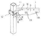
図1は棚板支持具の取り付け構造を示す外観斜視図、図2は同分解斜視図である。1は棚板支持具、11はラックの支柱、12は棚板支持具1の取り付け用のクランプであり、支柱11に装着固定されている。棚板支持具1が支柱11の適宜の高さに取り付けられることで、ラックの所望の高さ位置に棚板が設置使用される。 FIG. 1 is an external perspective view showing a mounting structure of a shelf board support, and FIG. 2 is an exploded perspective view of the same. Reference numeral 1 denotes a shelf support, 11 a rack post, and 12 a clamp for attaching the shelf support 1. By attaching the shelf support 1 to an appropriate height of the column 11, the shelf is installed and used at a desired height position of the rack.
棚板支持具1は、図3、図4に示すように、縦方向断面形状がコ字型の鋼材が適宜加工されて形成され、上下縁には相対するように水平部9のそれぞれを備えている。略45度折り曲げられた一方端部側が取り付け基部2となり他方側が棚板支持部3となっており、棚板支持部3の端部は徐々に細幅となっている。取り付け基部2には2個の係止用穴6が並設されている。係止用穴6のそれぞれは縦方向の長穴で傾斜しており、その下部がクランプ12面から突出する係止部14の差し入れ部15となっている。取り付け基部2の相対する水平部9のそれぞれは切り欠かれることで細幅となっており、その切り欠き加工によって折り曲げ位置近傍には当接角部10がそれぞれ形成されている。棚板支持部3の略中央位置には切り込み及び折り曲げ加工により裏側に突出する当接片19が形成され、端部近傍には吊り下げ係止用穴18が設けられている。 As shown in FIGS. 3 and 4, the shelf support 1 is formed by appropriately processing a steel material having a U-shaped longitudinal cross-sectional shape, and includes
棚板支持具1の取り付けは、取り付け基部2がラックの支柱11に取り付けられたクランプ12の側部に外嵌め装着され、その際係止用穴6それぞれの差し入れ部15からクランプ12側から突出する頭部が大径となった係止部14のそれぞれが差し入れられ、棚板支持具1が斜め方向に下降されることで係止用穴6に沿って係止部14が相対的に上昇して係止用穴6の上部に係止され、これにより棚板支持具1の係止取り付けが行われる。その際、図5に示すように、棚板支持具1がその係止用穴6の方向に沿って斜め方向に下降されることで、棚板支持具1の当接角部10のそれぞれが支柱11面に接近して当接固定され、これにより棚板支持具1はガタツクことなく安定して取り付けられる。棚板支持具1上に棚板が置かれて使用される際には当接角部10それぞれの支柱11面への当接が強固となって、より安定した状態となる。 The shelf support 1 is attached by attaching the
図6は非使用時において棚板支持具1をラックの支柱11に沿って収納保管した状態を示す。棚板支持具1は吊り下げ係止用穴18がクランプ12の一方の係止部14に係止されることで支柱11の側面に沿って吊り下げられて収納保管される。その際には、図7に示すように、棚板支持部3の端部21の内側面(位置決め当接部)21aとそれに続く水平部9の内側面(位置決め当接部)9aとがクランプ12面に当接するとともに、当接片19の端縁(位置決め当接部)19aが支柱11面に当接する。これにより棚板支持部3の横方向、前後方向への変位が規制され、棚板支持具1は支柱11の側面に納まり良く安定した状態で収納保管される。 FIG. 6 shows a state in which the shelf support 1 is stored and stored along the rack column 11 when not in use. The shelf board support 1 is suspended and stored along the side surface of the column 11 by the
1 棚板支持具
2 取り付け基部
3 棚板支持部
6 係止用穴
9a 水平部の内側面(位置決め当接部)
11 支柱
12 クランプ(取り付け部材)
14 係止部
19a 端縁(位置決め当接部)
21a 端部の内側面(位置決め当接部)DESCRIPTION OF SYMBOLS 1 Shelf
11
14 Locking
21a End side surface (positioning contact)
Claims (2)
前記取り付け部材に取り付け用の係止部が突設されるとともに、前記棚板支持具に縦方向に長く、かつ、傾斜して位置する係止用穴が設けられ、
前記係止用穴に前記係止部が係止されて前記棚板支持具が取り付けられる際、前記係止部が傾斜状態の前記係止用穴に沿って下方から上方に相対移動して前記棚板支持具が斜め方向に下降することで、前記棚板支持具がその一部において前記支柱の側面に当接固定されることを特徴とする棚板支持具の取り付け構造。In the mounting structure of the shelf support to the mounting member mounted on the rack column,
The mounting member is provided with a locking portion for mounting, and the shelf board support is provided with a locking hole that is long and inclined in the vertical direction,
When the locking portion is locked in the locking hole and the shelf board support is attached, the locking portion relatively moves from below to above along the locking hole in an inclined state. The shelf support member mounting structure, wherein the shelf support member descends in an oblique direction so that the shelf support member is in contact with and fixed to a side surface of the support column at a part thereof.
吊り下げ係止部と位置決め当接部とが設けられ、
前記位置決め当接部は、当該棚板支持具が非使用時において前記吊り下げ係止部により前記取り付け部材に吊り下げられて前記支柱に沿って収納保管される際に、前記取り付け部材及び又は前記支柱に当接して当該棚板支持具の位置決めを行うものである、
ことを特徴とする棚板支持具。In the shelf board support that is detachably attached to the attachment member attached to the rack column
A suspension locking part and a positioning contact part are provided,
The positioning contact portion is suspended from the attachment member by the suspension latching portion when the shelf board support is not in use and is stored and stored along the support column. Positioning the shelf support in contact with the support,
A shelf board support characterized by that.
Priority Applications (1)
| Application Number | Priority Date | Filing Date | Title |
|---|---|---|---|
| JP2017029457A JP2018122996A (en) | 2017-02-02 | 2017-02-02 | Fitting structure of shelf board support tool and shelf board support tool |
Applications Claiming Priority (1)
| Application Number | Priority Date | Filing Date | Title |
|---|---|---|---|
| JP2017029457A JP2018122996A (en) | 2017-02-02 | 2017-02-02 | Fitting structure of shelf board support tool and shelf board support tool |
Publications (1)
| Publication Number | Publication Date |
|---|---|
| JP2018122996A true JP2018122996A (en) | 2018-08-09 |
Family
ID=63110962
Family Applications (1)
| Application Number | Title | Priority Date | Filing Date |
|---|---|---|---|
| JP2017029457A Pending JP2018122996A (en) | 2017-02-02 | 2017-02-02 | Fitting structure of shelf board support tool and shelf board support tool |
Country Status (1)
| Country | Link |
|---|---|
| JP (1) | JP2018122996A (en) |
Cited By (1)
| Publication number | Priority date | Publication date | Assignee | Title |
|---|---|---|---|---|
| CN111517052A (en) * | 2020-04-27 | 2020-08-11 | 牛艺霏 | Goods shelf restraint device applied to transfer robot |
-
2017
- 2017-02-02 JP JP2017029457A patent/JP2018122996A/en active Pending
Cited By (1)
| Publication number | Priority date | Publication date | Assignee | Title |
|---|---|---|---|---|
| CN111517052A (en) * | 2020-04-27 | 2020-08-11 | 牛艺霏 | Goods shelf restraint device applied to transfer robot |
Similar Documents
| Publication | Publication Date | Title |
|---|---|---|
| JP2018122996A (en) | Fitting structure of shelf board support tool and shelf board support tool | |
| JP5773542B2 (en) | Bracket and shelf holder | |
| JP2015208593A (en) | Bracket and merchandise display store fixture using the same | |
| JP3204575U (en) | Wall hanging fixture | |
| JP2006345951A (en) | Storage shelf | |
| JP3168934U (en) | Shelf support | |
| JP2018175484A (en) | Partition body and shelf | |
| JP2017127435A (en) | Shelf protection plate and shelf | |
| KR101631490B1 (en) | Accessories hanger | |
| JP4480133B2 (en) | Storage device | |
| JP2020089467A (en) | Commodity mount shelf and show case | |
| JP2018186891A (en) | Shelving bracket | |
| KR101549520B1 (en) | Shelf supporting unit | |
| JP2006305024A (en) | Mounting structure of shelf bracket | |
| JP2020192238A (en) | Panel mounting structure on display shelf | |
| JP7158747B2 (en) | display fixtures | |
| JP2001104083A (en) | Wiring cover | |
| JP2012192147A (en) | Shelf bracket device | |
| JP4030773B2 (en) | table | |
| JP2018000450A (en) | Shelf plate supporting structure and shelf plate unit | |
| JP4424212B2 (en) | Storage body shelf support structure | |
| JPH0755948Y2 (en) | Bracket retaining device | |
| JP4103733B2 (en) | Bookend | |
| JP2024053146A (en) | Portable Frame | |
| KR200479896Y1 (en) | Fixing member for wall attachment shelf |