JP2018106982A - Rechargeable battery with self-cooling function - Google Patents
Rechargeable battery with self-cooling function Download PDFInfo
- Publication number
- JP2018106982A JP2018106982A JP2016253607A JP2016253607A JP2018106982A JP 2018106982 A JP2018106982 A JP 2018106982A JP 2016253607 A JP2016253607 A JP 2016253607A JP 2016253607 A JP2016253607 A JP 2016253607A JP 2018106982 A JP2018106982 A JP 2018106982A
- Authority
- JP
- Japan
- Prior art keywords
- housing
- self
- coolant
- cooling function
- secondary battery
- Prior art date
- Legal status (The legal status is an assumption and is not a legal conclusion. Google has not performed a legal analysis and makes no representation as to the accuracy of the status listed.)
- Pending
Links
Images


Classifications
-
- Y—GENERAL TAGGING OF NEW TECHNOLOGICAL DEVELOPMENTS; GENERAL TAGGING OF CROSS-SECTIONAL TECHNOLOGIES SPANNING OVER SEVERAL SECTIONS OF THE IPC; TECHNICAL SUBJECTS COVERED BY FORMER USPC CROSS-REFERENCE ART COLLECTIONS [XRACs] AND DIGESTS
- Y02—TECHNOLOGIES OR APPLICATIONS FOR MITIGATION OR ADAPTATION AGAINST CLIMATE CHANGE
- Y02E—REDUCTION OF GREENHOUSE GAS [GHG] EMISSIONS, RELATED TO ENERGY GENERATION, TRANSMISSION OR DISTRIBUTION
- Y02E60/00—Enabling technologies; Technologies with a potential or indirect contribution to GHG emissions mitigation
- Y02E60/10—Energy storage using batteries
Abstract
Description
本発明は、電池内部の熱暴走に対する自己冷却機能を発揮可能な自己冷却機能付き二次電池に関する。 The present invention relates to a secondary battery with a self-cooling function capable of exhibiting a self-cooling function against thermal runaway inside the battery.
近年、電気自動車やプラグインハイブリッド自動車をはじめ、各種の電動車両が実用化されている。当該電動車両に搭載された駆動用バッテリには、充電可能な二次電池が多数収容されている。かかる二次電池は、高いエネルギ密度を有し、長寿命であり、かつ、出力特性に優れている。 In recent years, various electric vehicles such as electric vehicles and plug-in hybrid vehicles have been put into practical use. Many rechargeable secondary batteries are accommodated in the drive battery mounted on the electric vehicle. Such a secondary battery has a high energy density, a long life, and excellent output characteristics.
ところで、二次電池は、例えば、短絡や過充電などによる温度上昇を引き起こす可能性がある。そして、温度上昇の程度によっては、電池内部の熱暴走に至る虞がある。そうなると、電解液が熱せられて膨張することで、二次電池の安全弁が作動(破裂)する場合がある。この場合、破裂した安全弁から可燃性の電解液が噴出し、これにより、周辺構成ないし周辺環境に影響を与えることは否めない。 By the way, the secondary battery may cause a temperature rise due to, for example, a short circuit or overcharge. And depending on the degree of temperature rise, there is a risk of thermal runaway inside the battery. If so, the safety valve of the secondary battery may be actuated (ruptured) due to the electrolyte being heated and expanding. In this case, it cannot be denied that the flammable electrolyte is ejected from the ruptured safety valve, thereby affecting the surrounding structure or the surrounding environment.
本発明の目的は、既存の安全弁とは別個の機能として、電池内部の熱暴走に対する自己冷却機能を発揮可能な自己冷却機能付き二次電池を提供することにある。 The objective of this invention is providing the secondary battery with a self-cooling function which can exhibit the self-cooling function with respect to the thermal runaway inside a battery as a function separate from the existing safety valve.
かかる目的を達成するために、本発明の自己冷却機能付き二次電池は、筐体の一部を貫通させて構成された流入通路と、流入通路を一時的にシールされた状態に維持する閉塞部材と、閉塞部材を覆うように設けられた冷却剤層と、冷却剤層の全体を覆うように設けられた保護層と、を有する。筐体の内部で熱暴走が発生した際、閉塞部材が溶融して流入通路が開口する。冷却剤層から冷却剤が、流入通路を通って筐体の内部に流入する。これにより、筐体の内部での熱暴走を冷却させる。 In order to achieve such an object, the secondary battery with a self-cooling function of the present invention includes an inflow passage configured by penetrating a part of the housing, and a blockage for temporarily maintaining the inflow passage in a sealed state. A member, a coolant layer provided so as to cover the blocking member, and a protective layer provided so as to cover the entire coolant layer. When a thermal runaway occurs inside the housing, the closing member melts and the inflow passage opens. The coolant flows from the coolant layer into the housing through the inflow passage. This cools the thermal runaway inside the housing.
本発明によれば、既存の安全弁とは別個の機能として、電池内部の熱暴走に対する自己冷却機能を発揮可能な自己冷却機能付き二次電池を実現することができる。 According to the present invention, a secondary battery with a self-cooling function capable of exhibiting a self-cooling function against thermal runaway inside the battery can be realized as a function separate from the existing safety valve.
「一実施形態」
図1に示すように、自己冷却機能付き二次電池1(以下、二次電池1と言う)の仕様として、電動車両2(例えば、電気自動車、プラグインハイブリッド自動車)には、駆動用バッテリ3(以下、電池パック3と言う)が搭載されている。図面では一例として、電池パック3は、車体2aの下回りに搭載されている。電池パック3には、多数の二次電池1が収容されている。二次電池1は、充電可能に構成されている。
"One embodiment"
As shown in FIG. 1, as a specification of a secondary battery 1 with a self-cooling function (hereinafter referred to as a secondary battery 1), an electric vehicle 2 (for example, an electric vehicle or a plug-in hybrid vehicle) includes a
図2に示すように、二次電池1は、例えば、金属製の筐体4と、負極5と、正極6と、セパレータ7と、図示しない電解液と、負極端子8と、正極端子9と、安全弁10と、を有している。なお、二時電池1には、後述する自己冷却構造11が構築されている。
As shown in FIG. 2, the secondary battery 1 includes, for example, a
筐体4は、中空の立方体形状を有している。筐体4の内部には、中空の収容(空間)領域4aが構成されている。収容(空間)領域4aは、筐体4の外部に対して液密(気密)的に密閉(密封)された状態に維持されている。収容(空間)領域4aには、負極5と、正極6と、セパレータ7と、電解水と、が収容されている。なお、筐体4は、立方体形状に限定されることは無く、他の形状(例えば、円筒、多角柱)であってもよい。
The
収容(空間)領域4aにおいて、負極5と正極6とは、交互に対向させて配置されている。セパレータ7は、絶縁性を有している。セパレータ7は、負極5と正極6との間に配置されている。セパレータ7は、負極5と正極6との間を絶縁している。なお、電解水には、二次電池1に適用可能な既製品が用いられるため、ここでは特に限定しない。
In the accommodation (space)
負極端子8及び正極端子9は、それぞれ、筐体4に固定されている。負極端子8は、上記した負極5に電気的に接続されている。正極端子9は、上記した正極6に電気的に接続されている。
The
安全弁10は、筐体4に設けられている。安全弁10は、例えば、筐体4の一部を薄肉化させて構成されている。安全弁10は、例えば、筐体4の内部の温度(圧力)が所定レベルを越えた際に動作(破裂)して、当該筐体4の破裂を防止可能に構成されている。安全弁10は、予め設定された温度帯域で、開弁可能に構成されている。ここで、予め設定された温度帯域としては、例えば、200℃以上に設定することができる。
The
「自己冷却構造11」
図3〜図4に示すように、自己冷却構造11は、筐体4の外周(面)4sに沿って構築されている。図面では一例として、自己冷却構造11は、筐体4の外周(面)4sの全体のうち、負極端子8及び正極端子9を回避した部分(領域)に沿って構築されている。なお、安全弁10は、自己冷却構造11を回避した部分(領域)に配置されている。これにより、自己冷却構造11の影響を受けること無く、安全弁10としての機能を発揮させることができる。
"Self-
As shown in FIGS. 3 to 4, the self-
自己冷却構造11は、例えば、短絡や過充電などにより、筐体4の内部で熱暴走が発生した際に、冷却剤12(図7参照)を筐体4の内部に流入させて冷却可能に構成されている。これにより、周辺構成ないし周辺環境に与える影響を未然に防止(抑制)することが可能となる。
The self-
自己冷却構造11は、流入通路13と、閉塞部材14と、冷却剤層15と、保護層16と、を備えている。以下具体的に説明する。
The self-
「流入通路13」
流入通路13は、筐体4の一部を貫通させて構成されている。流入通路13は、筐体4の内部と外部とを相互に連通可能な開口(孔)として構成されている。図面では一例として、3つの流入通路13が示されている。即ち、筐体4の側面、正面、底面に1つずつ流入通路13が設けられている。
"Inflow
The
ここで、例えば、1つの流入通路13だけでは、密閉(密封)された筐体4の内部(収容(空間)領域4a)に冷却剤をスムーズに流入させることが困難である。よって、少なくとも2つの流入通路13を設けることが好ましい。ただし、流入通路13の個数は、筐体4の強度との関係で設定されるため、ここでは特に限定しない。
Here, for example, with only one
更に、流入通路13を設ける場所(位置)としては、例えば、熱暴走が発生する可能性の高い場所(位置)に対して、なるべく接近させた場所(位置)に設定することが好ましい。これにより、冷却剤を熱暴走発生元に向けて効率よく短時間に流入させることができる。この結果、冷却時間を大幅に短縮化させることができる。
Furthermore, the place (position) where the
更に、流入通路13の大きさや形状は、例えば、筐体4の大きさや形状、或いは、冷却剤の種類などに応じて設定されるため、ここでは特に限定しない。図面では一例として、円形の流入通路13が示されている。円形は、外圧を均等に分散可能な形状であって、変形し難い形状である。これにより、円形の流入通路13は、常に一定の形状(輪郭)に維持可能となる。
Furthermore, since the size and shape of the
「閉塞部材14」
上記した流入通路13は、閉塞部材14によって液密(気密)的及び一時的にシールされた状態に維持されている。閉塞部材14は、流入通路13に付加(取付)可能に構成されている。付加(取付)方法としては、例えば、閉塞部材14を流入通路13に嵌め込んだり、圧入したり、接着したりする方法などが適用可能である。また、付加(取付)方向としては、例えば、筐体4の外部(外周(面)4s側)から閉塞部材14を流入通路13に付加したり、或いは、筐体4の内部(内側)から閉塞部材14を流入通路13に付加したりする方法が適用可能である。
"
The
要するに、閉塞部材14によって流入通路13が液密(気密)的にシールされた状態に維持できれば、どのような付加(取付)方法であってもよい。なお、閉塞部材14の材質としては、例えば、ポリエチレン、ポリスチレン、ポリプロピレンなどの素材を適用することができる。
In short, any addition (attachment) method may be used as long as the
更に、閉塞部材14としては、例えば、蓋や栓などのキャップ製品を適用することが可能である。閉塞部材14は、筐体4の内部に冷却剤を流入させる際に、溶解(融解)可能に構成されている。閉塞部材14は、予め設定された温度帯域で、溶解(融解)可能に構成されている。ここで、予め設定された温度帯域としては、例えば、100℃〜120℃以上に設定することができる。
Furthermore, as the closing
「冷却剤層15」
冷却剤層15は、筐体4の外周(面)4sに沿って設けられている。冷却剤層15は、筐体4の外周(面)4sに隣接させて設けられている。冷却剤層15は、上記した閉塞部材14に対向させて設けられている。冷却剤層15は、閉塞部材14を覆うように設けられている。冷却剤層15は、吸水(保水)性部材17と、上記した冷却剤12と、を備えている。
"
The
吸水(保水)性部材17として、例えば、スポンジなどの多孔質部材を適用することができる。多孔質部材は、内部に細かな孔が無数に空いた多孔質の柔らかい部材である。多孔質部材は、液体に浸すことで、孔内の空気と置換される形で液体を吸い取り可能に構成されている。同時に、多孔質部材は、外部からの力により、吸い取った液体を容易に放出可能に構成されている。
As the water absorbing (water retaining)
他の吸水(保水)性部材17としては、例えば、寒天、ゼラチン、シリカゲルなどの類に含まれるゲルを適用することができる。ゲルは、コロイド溶液が流動性を失い、多少の弾性と固さをもってゼリー状に固化したものである。
As the other water-absorbing (water retaining)
冷却剤12は、吸水(保水)性部材17に含浸させて構成されている。この場合、冷却剤12としては、例えば、ジブロモメタン(二臭化メタン)、ブロモホルム(四臭化炭素)などを主成分としたもの適用することができる。ジブロモメタン(二臭化メタン)は、例えば、110℃以上で気化される。ブロモホルム(四臭化炭素)は、例えば、150℃から200℃程度で気化される。かかる冷却剤12は、例えば、加熱(燃焼)により高温環境に晒されると、分解して気化(例えば、エアロゾル化、ミスト化)する特性を有している。
The
他の冷却剤12としては、例えば、炭酸カリウム、炭酸水素カリウム、炭酸アンモニウム、炭酸水素アンモニウムなどのアルカリ性吸熱物質を主成分としたもの、或いは、リン酸アンモニウム、リン酸水素アンモニウム、硫酸アンモニウムなどの酸性吸熱物質を主成分としたもの、などを適用することができる。
Examples of the
なお、冷却剤層15の容量(例えば、吸水(保水)性部材17に含浸させる冷却剤12の容量)については、例えば、筐体4の内部(収容(空間)領域4a)の広さ(大きさ)や、冷却剤12の種類(例えば、冷却性能)などに応じて設定されるため、ここでは特に限定しない。要するに、冷却剤層15の容量は、筐体4の内部の熱暴走を冷却するのに充分な程度に設定される。
As for the capacity of the coolant layer 15 (for example, the capacity of the
「保護層16」
保護層16は、冷却剤層15の全体を覆うように設けられている。保護層16は、例えば、耐熱性、耐久性、耐衝撃性に優れた材料(保護材)で構成されている。保護材としては、例えば、ガラス、セラミックなどの素材を適用することができる。
"
The
かかる保護層16によれば、例えば、外的要因(圧力、衝撃)により冷却剤層15が破損して、冷却剤12が外部に漏洩するといった事態を回避することができる。更に、かかる保護層16によれば、例えば、筐体4の内部の熱暴走に際し、外部への放熱を遮断することができる。
According to the
「自己冷却機能付き二次電池1の製造方法」
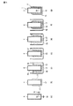
図5には、二次電池1の製造方法のうち、自己冷却構造11を、筐体4の外周に沿って構築するプロセス(a)〜(g)が示されている。かかるプロセスに際し、二次電池1の中身(例えば、負極5、正極6、セパレータ7、電解液、負極端子8、正極端子9)は、筐体4に収容されていない。換言すると、筐体4のみに対して、後述する第1〜第7プロセス(a)〜(g)が施される。
“Method of manufacturing secondary battery 1 with self-cooling function”
FIG. 5 shows processes (a) to (g) for building the self-cooling
第1プロセス(a)において、筐体4の予め設定した位置に2つの流入通路13を構成する。そして、各々の流入通路13に閉塞部材14を付加してシールする。
In the first process (a), two
第2プロセス(b)において、閉塞部材14を覆うように、吸水(保水)性部材17を筐体4に固定する。なお、固定方法としては、例えば、接着、ネジ止めなど、既存の方法を適用することができる。
In the second process (b), the water absorbing (water retaining)
第3プロセス(c)において、吸水(保水)性部材17と共に、筐体4を、冷却剤12を溶解させた冷却剤溶液18に浸漬する。冷却剤12を、吸水(保水)性部材17に含浸させて、冷却剤層15を構成させる。
In the third process (c), the
第4プロセス(d)において、筐体4を冷却剤溶液18から引き出した後、冷却剤層15、即ち、吸水(保水)性部材17を乾燥させる。このとき、例えば、常温、又は、加熱による自然乾燥が行われる。加熱する場合には、例えば、閉塞部材14が溶融しない程度の温度に設定する。
In the fourth process (d), after the
第5プロセス(e)において、乾燥済みの吸水(保水)性部材17と共に、筐体4を、保護材を溶解させた保護材溶液19に浸漬する。吸水(保水)性部材17の全体を覆うように保護層16をコーティングする。
In the fifth process (e), the
第6プロセス(f)において、筐体4を保護材溶液19から引き出した後、保護層16を乾燥させる。このとき、例えば、常温、又は、加熱による自然乾燥が行われる。加熱する場合には、例えば、閉塞部材14が溶融しない程度の温度に設定する。
In the sixth process (f), after the
第7プロセス(g)において、各種の仕上げ処理が行われた後、自己冷却機能付き二次電池1が完成する。 In the seventh process (g), after various finishing processes are performed, the secondary battery 1 with a self-cooling function is completed.
「自己冷却機能付き二次電池1の作用(特長)」
二次電池1の通常運転時(熱暴走に至る以前)において、筐体4の内部の圧力P1と、冷却剤層15の内部の圧力P2とは、P1=P2なる関係に維持されている。このとき、筐体4の内部の温度T1(例えば、T1<80℃)と、冷却剤層15の内部の温度T2とは、T1=T2なる関係に維持されている。
"Operation (features) of secondary battery 1 with self-cooling function"
During normal operation of the secondary battery 1 (before thermal runaway), the pressure P1 inside the
図6に示すように、例えば、短絡や過充電などにより筐体4の内部で熱暴走が発生した状態(際)において、筐体4の内部の圧力P1と、冷却剤層15の内部の圧力P2とは、P1<P2なる関係となる。このとき、筐体4の内部の温度T1(例えば、120℃<T1)と、冷却剤層15の内部の温度T2とは、T1>T2なる関係となる。
As shown in FIG. 6, for example, when a thermal runaway occurs inside the
このとき、熱暴走により熱せられた閉塞部材14は、当該閉塞部材14自身の温度が100℃ないし120℃に達すると溶融する。これにより、筐体4の内部の圧力P1が上昇する前に、流入通路13が開口する。この結果、P1<P2なる関係が維持される。
At this time, the closing
図7に示すように、かかる状態(P1<P2)において、やがて冷却剤層15の内部の温度T2が、110℃(150℃)に達する。そうすると、冷却剤12が気化(エアロゾル化、ミスト化)する。これにより、筐体4の内部の圧力P1が上昇する前に、冷却剤層15の内部の圧力P2が上昇する。この結果、気化状態の冷却剤12が、冷却剤層15から流入通路13を通って筐体4の内部に流入する。流入した気化状態の冷却剤12は、筐体4の内部の隅々に亘って対流する。
As shown in FIG. 7, in this state (P1 <P2), the temperature T2 inside the
かくして、筐体4の内部の熱暴走が冷却される。このとき、筐体4の内部の圧力P1と、冷却剤層15の内部の圧力P2とは、P1=P2なる関係に維持される。筐体4の内部の温度T1と、冷却剤層15の内部の温度T2とは、T1=T2なる関係に維持される。
Thus, the thermal runaway inside the
「一実施形態の効果」
本実施形態によれば、既存の安全弁10とは別個の機能として、自己冷却機能を二次電池1に持たせる。これにより、筐体4の内部の熱暴走に対する自己冷却機能を独自に発揮することができる。この結果、周辺構成ないし周辺環境に与える影響を未然に抑制(防止)することができる。
"Effect of one embodiment"
According to the present embodiment, the secondary battery 1 is provided with a self-cooling function as a function separate from the existing
本実施形態によれば、気化(エアロゾル化、ミスト化)状態の冷却剤12が、冷却剤層15から筐体4の内部に流入する。このとき、気化状態の冷却剤12は、短時間のうちに筐体4の内部の隅々に亘って対流する。かくして、筐体4の内部の熱暴走を短時間で確実に冷却させることができる。
According to this embodiment, the vaporized (aerosolized, misted)
本実施形態によれば、流入通路13を設ける場所(位置)を、熱暴走が生じる可能性の高い場所(位置)に接近させて設定する。これにより、冷却剤12を熱暴走発生元に向けて効率よく短時間に流入させることができる。この結果、冷却に要する時間を大幅に短縮化できると共に、自己冷却機能の精度を高めることができる。
According to this embodiment, the place (position) where the
本実施形態によれば、筐体4に少なくとも2つの流入通路13を設ける。これにより、密閉(密封)された筐体4の内部(収容(空間)領域4a)に、冷却剤12をスムーズに流入させることができる。この結果、冷却効率を飛躍的に向上させることができる。
According to this embodiment, at least two
1…自己冷却機能付き二次電池、4…筐体、10…安全弁、11…自己冷却構造、
12…冷却剤、13…流入通路、14…閉塞部材、15…冷却剤層、16…保護層、
17…吸水(保水)性部材。
DESCRIPTION OF SYMBOLS 1 ... Secondary battery with a self-cooling function, 4 ... Case, 10 ... Safety valve, 11 ... Self-cooling structure,
12 ... Coolant, 13 ... Inflow passage, 14 ... Blocking member, 15 ... Coolant layer, 16 ... Protective layer,
17: Water absorbing (water retaining) member
Claims (6)
前記筐体の一部を貫通させて構成された流入通路と、
前記流入通路を一時的にシールされた状態に維持する閉塞部材と、
前記閉塞部材を覆うように設けられた冷却剤層と、
前記冷却剤層の全体を覆うように設けられた保護層と、を有し、
前記筐体の内部で熱暴走が発生した際、前記閉塞部材が溶融して前記流入通路が開口し、前記冷却剤層から冷却剤が、前記流入通路を通って前記筐体の内部に流入することで、前記筐体の内部での熱暴走を冷却させる自己冷却機能付き二次電池。 A secondary battery with a self-cooling function capable of exhibiting a self-cooling function against thermal runaway inside the housing,
An inflow passage configured to penetrate a part of the housing;
A closing member for maintaining the inflow passage in a temporarily sealed state;
A coolant layer provided to cover the closure member;
A protective layer provided so as to cover the entire coolant layer,
When a thermal runaway occurs inside the housing, the closing member melts and the inflow passage opens, and the coolant flows from the coolant layer into the housing through the inflow passage. Thus, a secondary battery with a self-cooling function that cools thermal runaway inside the housing.
前記冷却剤は、前記吸水(保水)性部材に含浸させて構成されている請求項1に記載の自己冷却機能付き二次電池。 The coolant layer includes a water absorbing (water retaining) member and a coolant,
The secondary battery with a self-cooling function according to claim 1, wherein the coolant is formed by impregnating the water absorbing (water retaining) member.
Priority Applications (1)
| Application Number | Priority Date | Filing Date | Title |
|---|---|---|---|
| JP2016253607A JP2018106982A (en) | 2016-12-27 | 2016-12-27 | Rechargeable battery with self-cooling function |
Applications Claiming Priority (1)
| Application Number | Priority Date | Filing Date | Title |
|---|---|---|---|
| JP2016253607A JP2018106982A (en) | 2016-12-27 | 2016-12-27 | Rechargeable battery with self-cooling function |
Publications (1)
| Publication Number | Publication Date |
|---|---|
| JP2018106982A true JP2018106982A (en) | 2018-07-05 |
Family
ID=62787454
Family Applications (1)
| Application Number | Title | Priority Date | Filing Date |
|---|---|---|---|
| JP2016253607A Pending JP2018106982A (en) | 2016-12-27 | 2016-12-27 | Rechargeable battery with self-cooling function |
Country Status (1)
| Country | Link |
|---|---|
| JP (1) | JP2018106982A (en) |
-
2016
- 2016-12-27 JP JP2016253607A patent/JP2018106982A/en active Pending
Similar Documents
| Publication | Publication Date | Title |
|---|---|---|
| KR101743697B1 (en) | Battery module having separated cooling path and venting path and battery pack including the same | |
| KR101609212B1 (en) | Battery Module Having Structure for Prevention of Coolant and Venting Gas Mixing | |
| US20180287227A1 (en) | Battery pack for vehicle, and vehicle | |
| US9755285B2 (en) | Frame for secondary battery and battery module comprising the same | |
| JP6600750B2 (en) | Secondary battery cartridge and battery module including the same | |
| KR102555751B1 (en) | Gas Dischargeable Pouch-Type Case for Secondary Battery | |
| TWI442614B (en) | Battery | |
| JP7403857B2 (en) | Thermal management of electrochemical storage devices | |
| KR20190042215A (en) | Secondary Battery Pouch-Type Case Having Gas Discharge Port | |
| JP7208145B2 (en) | power supply | |
| KR101793729B1 (en) | Pouch type secondary battery and a method of making the same | |
| JP7377591B2 (en) | Pouch type battery cell with venting part attached and method for manufacturing the same | |
| KR102329343B1 (en) | Battery module with enhanced cooling efficiency and Battery pack comprising the same | |
| KR20120139970A (en) | Battery cell with safety apparatus | |
| KR102202417B1 (en) | The cartridge, Battery module including the cartridge, Battery pack | |
| JP2005322434A (en) | Battery module and battery pack | |
| KR101806733B1 (en) | Cooling structure for battery cell | |
| KR20130050557A (en) | Battery cell, and secondary battery | |
| JP7174707B2 (en) | power supply | |
| US20220166103A1 (en) | Metal-ion accumulator provided with a degassing duct, associated battery module or battery pack with liquid cooling | |
| KR101773333B1 (en) | Secondary battery and battery module having the same | |
| JPWO2020054229A1 (en) | Power supply | |
| JPH10340739A (en) | Secondary lithium ion battery | |
| JP7046207B2 (en) | Battery module including module housing | |
| JP2006202655A (en) | Battery pack |