JP2018106968A - Spark plug - Google Patents
Spark plug Download PDFInfo
- Publication number
- JP2018106968A JP2018106968A JP2016253243A JP2016253243A JP2018106968A JP 2018106968 A JP2018106968 A JP 2018106968A JP 2016253243 A JP2016253243 A JP 2016253243A JP 2016253243 A JP2016253243 A JP 2016253243A JP 2018106968 A JP2018106968 A JP 2018106968A
- Authority
- JP
- Japan
- Prior art keywords
- insulator
- peak
- outer peripheral
- peaks
- spark plug
- Prior art date
- Legal status (The legal status is an assumption and is not a legal conclusion. Google has not performed a legal analysis and makes no representation as to the accuracy of the status listed.)
- Granted
Links
Images


Classifications
-
- H—ELECTRICITY
- H01—ELECTRIC ELEMENTS
- H01T—SPARK GAPS; OVERVOLTAGE ARRESTERS USING SPARK GAPS; SPARKING PLUGS; CORONA DEVICES; GENERATING IONS TO BE INTRODUCED INTO NON-ENCLOSED GASES
- H01T13/00—Sparking plugs
- H01T13/02—Details
- H01T13/14—Means for self-cleaning
-
- H—ELECTRICITY
- H01—ELECTRIC ELEMENTS
- H01T—SPARK GAPS; OVERVOLTAGE ARRESTERS USING SPARK GAPS; SPARKING PLUGS; CORONA DEVICES; GENERATING IONS TO BE INTRODUCED INTO NON-ENCLOSED GASES
- H01T13/00—Sparking plugs
- H01T13/20—Sparking plugs characterised by features of the electrodes or insulation
-
- H—ELECTRICITY
- H01—ELECTRIC ELEMENTS
- H01T—SPARK GAPS; OVERVOLTAGE ARRESTERS USING SPARK GAPS; SPARKING PLUGS; CORONA DEVICES; GENERATING IONS TO BE INTRODUCED INTO NON-ENCLOSED GASES
- H01T13/00—Sparking plugs
- H01T13/02—Details
-
- H—ELECTRICITY
- H01—ELECTRIC ELEMENTS
- H01T—SPARK GAPS; OVERVOLTAGE ARRESTERS USING SPARK GAPS; SPARKING PLUGS; CORONA DEVICES; GENERATING IONS TO BE INTRODUCED INTO NON-ENCLOSED GASES
- H01T13/00—Sparking plugs
- H01T13/20—Sparking plugs characterised by features of the electrodes or insulation
- H01T13/36—Sparking plugs characterised by features of the electrodes or insulation characterised by the joint between insulation and body, e.g. using cement
-
- H—ELECTRICITY
- H01—ELECTRIC ELEMENTS
- H01T—SPARK GAPS; OVERVOLTAGE ARRESTERS USING SPARK GAPS; SPARKING PLUGS; CORONA DEVICES; GENERATING IONS TO BE INTRODUCED INTO NON-ENCLOSED GASES
- H01T21/00—Apparatus or processes specially adapted for the manufacture or maintenance of spark gaps or sparking plugs
- H01T21/02—Apparatus or processes specially adapted for the manufacture or maintenance of spark gaps or sparking plugs of sparking plugs
-
- H—ELECTRICITY
- H01—ELECTRIC ELEMENTS
- H01T—SPARK GAPS; OVERVOLTAGE ARRESTERS USING SPARK GAPS; SPARKING PLUGS; CORONA DEVICES; GENERATING IONS TO BE INTRODUCED INTO NON-ENCLOSED GASES
- H01T13/00—Sparking plugs
- H01T13/20—Sparking plugs characterised by features of the electrodes or insulation
- H01T13/38—Selection of materials for insulation
Abstract
Description
本発明はスパークプラグに関し、特に絶縁体の強度低下を抑制できるスパークプラグに関するものである。 The present invention relates to a spark plug, and more particularly to a spark plug that can suppress a decrease in strength of an insulator.
スパークプラグは、アルミナ等のセラミックスで作られた絶縁体を、エンジンに取り付けられる主体金具が保持する(特許文献1)。エンジンに取り付けられたスパークプラグの絶縁体の表面に水分(結露など)や燃料(以下「水分等」と称す)が付着して、水分等がセラミックスの粒界のガラス相と反応すると、ガラス相が劣化して絶縁体の強度が低下するおそれがある。 In the spark plug, an insulator made of ceramics such as alumina is held by a metal shell attached to the engine (Patent Document 1). When moisture (condensation etc.) or fuel (hereinafter referred to as “moisture etc.”) adheres to the surface of the insulator of the spark plug attached to the engine and the moisture reacts with the glass phase of the ceramic grain boundary, May deteriorate, and the strength of the insulator may be reduced.
上記従来の技術において、水分等とガラス相との反応に起因する絶縁体の強度低下の抑制に対する要求がある。 In the above-described conventional technology, there is a demand for suppression of a decrease in strength of an insulator due to a reaction between moisture and the glass phase.
本発明は上述した要求に応えるためになされたものであり、絶縁体の強度低下を抑制できるスパークプラグを提供することを目的としている。 The present invention has been made to meet the above-described demand, and an object thereof is to provide a spark plug that can suppress a decrease in strength of an insulator.
この目的を達成するために本発明のスパークプラグは、先端側から後端側へと軸線に沿って延びる筒状の絶縁体の外周面に形成された係合部の後端部と、絶縁体の外周面に配置される筒状の主体金具の被係合部と、が係合する。絶縁体は、外周面のうち係合部よりも先端側の少なくとも一部に、自身の周方向に螺旋状に延びる凹凸が形成されている。 In order to achieve this object, a spark plug according to the present invention includes a rear end portion of an engaging portion formed on an outer peripheral surface of a cylindrical insulator extending along the axis from the front end side to the rear end side, and an insulator. Are engaged with engaged portions of a cylindrical metal shell disposed on the outer peripheral surface. As for the insulator, the unevenness | corrugation extended helically in the own circumferential direction is formed in at least one part of the front end side rather than an engaging part among outer peripheral surfaces.
請求項1記載のスパークプラグによれば、絶縁体の外周面に螺旋状の凹凸が形成されているので、絶縁体に付着した水分等を凹凸に沿って薄く広げることができる。水分等がセラミックスの粒界のガラス相と反応する前に、絶縁体の外周面に薄く広がった水分等を蒸発させ易くできるので、ガラス相の劣化による絶縁体の強度低下を抑制できる効果がある。 According to the spark plug of the first aspect, since the spiral irregularities are formed on the outer peripheral surface of the insulator, moisture or the like attached to the insulator can be spread thinly along the irregularities. Before moisture reacts with the glass phase at the grain boundaries of ceramics, it is easy to evaporate the moisture that spreads thinly on the outer peripheral surface of the insulator, which has the effect of suppressing the strength reduction of the insulator due to deterioration of the glass phase .
請求項2記載のスパークプラグによれば、凹凸は、絶縁体の軸線を含む断面に現れる外周面の実表面の断面曲線にフーリエ変換を施して得られる1〜300Hzにおける周波数nの振幅f(n)について、f(n+1)−f(n)の絶対値の大きいものから順に第1ピーク、第2ピーク、第3ピーク、第4ピークとするときに(但し、±2Hz以内に存在する2つ以上のピークは1つのピークとする)、第1ピークは20〜300Hzに存在し、且つ、第1ピーク、第2ピーク、第3ピーク及び第4ピークのうちの2つ以上のピークは30〜300Hzに存在する。第1ピーク、第2ピーク、第3ピーク及び第4ピークのうち3つ以上のピークは1〜20Hzに存在しない。凹凸を周期的にできるので、請求項1の効果に加え、絶縁体の外周面の輪郭のばらつきを小さくできる効果がある。
According to the spark plug according to
以下、本発明の好ましい実施形態について添付図面を参照して説明する。図1は本発明の一実施の形態におけるスパークプラグ10の片側断面図である。図1では、紙面下側をスパークプラグ10の先端側、紙面上側をスパークプラグ10の後端側という。スパークプラグ10は、絶縁体11及び主体金具30を備えている。
Hereinafter, preferred embodiments of the present invention will be described with reference to the accompanying drawings. FIG. 1 is a half sectional view of a
絶縁体11は、機械的特性や高温下の絶縁性に優れるアルミナ等のセラミックスにより形成された筒状の部材である。絶縁体11は、軸線Oに沿って貫通する軸孔12が形成されている。絶縁体11は、後端側から先端側へと軸線Oに沿って第1部13、係合部14、第2部15及び第3部16が連接されている。
The insulator 11 is a cylindrical member formed of ceramics such as alumina that is excellent in mechanical properties and insulation at high temperatures. The insulator 11 is formed with a
第1部13は、絶縁体11の後端の円筒状の部分である。係合部14は、第1部13よりも大径の外周縁をもつ円環状の部分である。第2部15は、第1部13及び係合部14よりも小径の円筒状の部分である。第3部16は、第2部15よりも小径の円筒状の部分である。絶縁体11は、第2部15と第3部16との境界に、先端側へ向かうにつれて外周が縮径する縮径部17が形成されている。第2部15の先端および第3部16の内側の部分の軸孔12に中心電極20が配置されている。
The
中心電極20は、軸線Oに沿って延びる棒状の部材であり、銅または銅を主成分とする芯材がニッケル又はニッケル基合金で覆われている。中心電極20は絶縁体11に保持され、先端が軸孔12から露出する。
The
端子金具21は、高圧ケーブル(図示せず)が接続される棒状の部材であり、導電性を有する金属材料(例えば低炭素鋼等)によって形成されている。端子金具21は、先端側が軸孔12に圧入された状態で、絶縁体11の後端に固定されている。端子金具21は、軸孔12の内部で中心電極20と電気的に接続されている。絶縁体11は、端子金具21と軸線O方向に間隔をあけて、外周の先端側に主体金具30が固定されている。
The
主体金具30は、導電性を有する金属材料(例えば低炭素鋼等)によって形成される略円筒状の部材である。主体金具30は、先端側の外周面にねじ部31が形成されている。エンジン41のねじ穴にねじ部31が結合して主体金具30がエンジン41に取り付けられる。主体金具30は、ねじ部31の径方向の内側の内周に、径方向の内側へ向かって突出する棚部32が形成されている。
The
主体金具30は、ねじ部31よりも後端側に、径方向の外側へ鍔状に張り出す円環状の座部33が設けられている。座部33とねじ部31との間に、エンジン41のねじ穴からの燃焼ガスの漏洩を防止するガスケット36が配置される。主体金具30は、座部33よりも後端側にレンチ等の工具が係合する工具係合部34が設けられている。工具係合部34に係合した工具によって、エンジン41のねじ穴にねじ部31がねじ込まれる。
The
主体金具30は、工具係合部34の後端に被係合部35が連接されている。被係合部35は、主体金具30の後端縁が内側に折り曲げられた部分である。絶縁体11は、第1部13の外周に軸線O方向に間隔をあけて2つのリング部材37が配置されている。リング部材37は主体金具30の工具係合部34の径方向の内側に配置され、リング部材37、第1部13及び工具係合部34に囲まれた空間にタルク等の粉末38が充填されている。被係合部35は、リング部材37及び粉末38を介して絶縁体11の係合部14の後端部と係合する。
The
主体金具30は、絶縁体11の縮径部17に棚部32が係合した状態で、被係合部35が内側に折り曲げられ、被係合部35が絶縁体11の係合部14と係合する。被係合部35の屈曲により、主体金具30が絶縁体11に加締め固定される。絶縁体11は、軸線O方向の両側から被係合部35及び棚部32に係合部14及び縮径部17が挟まれて、主体金具30に保持される。
In the
接地電極40は、主体金具30の先端に接合される金属製(例えばニッケル基合金製)の部材である。本実施の形態では、接地電極40は棒状に形成されており、先端側が屈曲し中心電極20と対向する。接地電極40は、中心電極20との間に火花ギャップを形成する。
The
スパークプラグ10は、例えば、以下のような方法によって製造される。絶縁体11は、原料粉末から成形された成形体を焼成することにより作成される。まず、主成分であるアルミナと、ガラス相を形成して焼結助剤として機能するSi,Mg,Ca,Ba等の元素の化合物と、を配合して原料粉末を準備する。ポリビニルアルコール等の親水性結合剤と水等の溶媒とを原料粉末に加え、混合してスラリーを調製する。スラリーをスプレードライ法等により乾燥し、造粒物を調製する。得られた造粒物を加圧成形または射出成形することにより成形体を得る。成形体を焼成して絶縁体11が得られる。得られた絶縁体11に研削加工が施される。
The
研削加工では、絶縁体11は第1部13がチャック(図示せず)に固定される。軸線Oを中心にチャックを回転させながら、係合部14、第2部15、縮径部17及び第3部16の外周面をバイト又は砥石(いずれも図示せず)で研削する。削り代は100〜500μm程度である。軸線Oを中心に絶縁体11を回転させながらバイト又は砥石を軸線O方向に移動させることにより、係合部14、第2部15、縮径部17及び第3部16の外周面に、周方向に螺旋状に延びる凹凸50(図2参照)が形成される。
In the grinding process, the
次いで、中心電極20を絶縁体11の軸孔12に挿入する。中心電極20は先端が軸孔12から外部に露出するように配置される。軸孔12に端子金具21を挿入し、端子金具21と中心電極20との導通を確保した後、予め接地電極40が接合された主体金具30を絶縁体11の外周に組み付ける。接地電極40が中心電極20と対向するように接地電極40を屈曲して、スパークプラグ10を得る。
Next, the
図2から図5を参照して、絶縁体11の外周面の形状について説明する。図2は絶縁体11の外周面の実表面の断面曲線であり、絶縁体11に形成された凹凸50の輪郭が示されている。図2では横軸に軸線O方向の長さをとり、縦軸に高さをとる。実表面の断面曲線は、軸線Oを含む平面によって絶縁体11の外周面を切断した切り口に現れる曲線(低域フィルタや高域フィルタによってカットオフされていない実測値)である。実表面の断面曲線は、JIS B0601(2013年版)に基づき、接触式の表面粗さ測定機により測定される。
The shape of the outer peripheral surface of the insulator 11 will be described with reference to FIGS. FIG. 2 is a cross-sectional curve of the actual surface of the outer peripheral surface of the insulator 11, and shows the contour of the
図2には、絶縁体11のうち第2部15の実表面の断面曲線が図示されている。図2に示す実表面の断面曲線は、軸線O方向に長さ4mmの部分の凹凸50の輪郭である。但し、図2には3mmの範囲の断面曲線を示す。図2から明らかなように、絶縁体11の凹凸50は規則的に形成されている。実表面の断面曲線を、例えば32768点のデジタルデータとして読み込み、フーリエ変換により周波数n(但し1Hz≦n≦300Hz)の振幅f(n)を求める。
FIG. 2 shows a cross-sectional curve of the actual surface of the
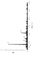
図3は、図2に示す実表面の断面曲線に高速フーリエ変換を施して得られたスペクトルである。図3では横軸に周波数をとり、縦軸に振幅をとる。図3に示すスペクトルは、実部および虚部のスペクトル成分が混在する。図3に示すようにスペクトルは、大きな振幅をもつ周波数(ピーク)が離散的に存在することがわかる。即ち、凹凸50は周期性をもった波形(輪郭)である。スペクトルのベースラインのばらつきを少なくするために、周波数nの振幅f(n)についてf(n+1)−f(n)を算出する。スペクトル成分は実部および虚部から構成されるので、実部と虚部とに分けて計算を行い、絶対値をとる。
FIG. 3 is a spectrum obtained by performing fast Fourier transform on the cross-sectional curve of the actual surface shown in FIG. In FIG. 3, the horizontal axis represents frequency and the vertical axis represents amplitude. The spectrum shown in FIG. 3 is a mixture of real and imaginary spectral components. As can be seen from FIG. 3, the spectrum has discrete frequencies (peaks) having large amplitudes. That is, the
図4は実部のf(n+1)−f(n)の絶対値をとった結果であり、図5は虚部のf(n+1)−f(n)の絶対値をとった結果である。図4において、絶対値の大きいものから第1ピーク51、第2ピーク52、第3ピーク53、第4ピーク54とする。同様に図5において、絶対値の大きいものから第1ピーク61、第2ピーク62、第3ピーク63、第4ピーク64とする。
FIG. 4 shows the result of taking the absolute value of f (n + 1) −f (n) of the real part, and FIG. 5 shows the result of taking the absolute value of f (n + 1) −f (n) of the imaginary part. In FIG. 4, the
ここで、第1ピーク51,61から第4ピーク54,64を求めるときに、±2Hz以内に存在する2つ以上のピークは1つのピークとみなす。サンプリング周波数(実表面の断面曲線を読み込んだデータ数の逆数)が大きくなりデータ数が多くなるにつれて、±2Hz以内に存在するピークの数が増えるので、サンプリング周波数に依存したピークの誤検出を防ぐためである。
Here, when the
図4及び図5に示すように、第1ピーク51,61は20〜300Hzに存在し、且つ、第1ピーク51,61、第2ピーク52,62、第3ピーク53,63及び第4ピーク54,64のうちの2つ以上のピークは30〜300Hzに存在する。第1ピーク51,61、第2ピーク52,62、第3ピーク53,63及び第4ピーク54,64のうち3つ以上のピークは1〜20Hzに存在しない。
As shown in FIGS. 4 and 5, the
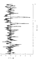
一方、研削加工が施されていない絶縁体(以下「比較例における絶縁体」と称す)の実表面の断面曲線を図6に示す。図6では横軸に軸線O方向の長さをとり、縦軸に高さをとる。図6に示す実表面の断面曲線は、軸線O方向に長さ4mmの部分の輪郭である。但し、図6には3mmの範囲の断面曲線を示す。実表面の断面曲線を、例えば32768点のデジタルデータとして読み込み、フーリエ変換により周波数n(但し1Hz≦n≦300Hz)の振幅f(n)を求める。 On the other hand, FIG. 6 shows a cross-sectional curve of an actual surface of an insulator that has not been ground (hereinafter referred to as “insulator in a comparative example”). In FIG. 6, the horizontal axis represents the length in the direction of the axis O, and the vertical axis represents the height. The cross-sectional curve of the actual surface shown in FIG. 6 is the outline of a portion having a length of 4 mm in the axis O direction. However, FIG. 6 shows a cross-sectional curve in the range of 3 mm. The cross-sectional curve of the actual surface is read as, for example, 32768 digital data, and the amplitude f (n) of the frequency n (where 1 Hz ≦ n ≦ 300 Hz) is obtained by Fourier transform.
図7は、図6に示す実表面の断面曲線に高速フーリエ変換を施して得られたスペクトルである。図7では横軸に周波数をとり、縦軸に振幅をとる。図7に示すスペクトルは、実部および虚部のスペクトル成分が混在する。スペクトルのベースラインのばらつきを少なくするために、周波数nの振幅f(n)についてf(n+1)−f(n)を算出する。図8は実部のf(n+1)−f(n)の絶対値をとった結果であり、図9は虚部のf(n+1)−f(n)の絶対値をとった結果である。 FIG. 7 is a spectrum obtained by performing fast Fourier transform on the cross-sectional curve of the actual surface shown in FIG. In FIG. 7, the horizontal axis represents frequency and the vertical axis represents amplitude. The spectrum shown in FIG. 7 has a mixture of real and imaginary spectral components. In order to reduce the variation of the spectrum baseline, f (n + 1) −f (n) is calculated for the amplitude f (n) of the frequency n. FIG. 8 shows the result of taking the absolute value of f (n + 1) −f (n) of the real part, and FIG. 9 shows the result of taking the absolute value of f (n + 1) −f (n) of the imaginary part.
図8において、絶対値の大きいものから第1ピーク71、第2ピーク72、第3ピーク73、第4ピーク74とし、図9において、絶対値の大きいものから第1ピーク71、第2ピーク72、第3ピーク73、第4ピーク74とする。なお、第1ピーク71,81から第4ピーク74,84を求めるときに、±2Hz以内に存在する2つ以上のピークは1つのピークとみなす。
In FIG. 8, the
図8及び図9に示すように、第1ピーク71,81は1〜20Hzに存在し、第1ピーク71,81、第2ピーク72,82、第3ピーク73,83及び第4ピーク74,84のうち3つ以上のピークは1〜20Hzに存在する。
As shown in FIGS. 8 and 9, the
以上のように絶縁体11の凹凸50は、1〜20Hzの低周波数域のピークが少なく、それよりも高い高周波数域のピークが多いので、絶縁体11の表面に付着した水分等(水分(結露など)や燃料)を凹凸50に沿って薄く広げることができる。凹凸50は周方向に螺旋状に延びるので、絶縁体11の表面に付着した水分等の量が多くても、凹凸50の螺旋に沿って水分等を周方向および軸方向に広げることができる。その結果、絶縁体11を構成するセラミックスの粒界のガラス相と反応する前に、絶縁体11の外周面に薄く広がった水分等を蒸発させ易くできるので、ガラス相の劣化による絶縁体11の強度低下を抑制できる。
As described above, the
これに対し、比較例における絶縁体のように表面の輪郭に1〜20Hzの低周波数域のピークが多く、それよりも高い高周波数域のピークが少ないと、絶縁体の表面に付着した水分等の大小の液滴が形を変え難く、絶縁体11の外周面に薄く広がらない。しかして、絶縁体の表面に付着した水分等の液滴は蒸発し難いので、セラミックスの粒界のガラス相と水分等が反応し易くなる可能性がある。セラミックスの粒界のガラス相が反応してガラス相が劣化すると、絶縁体の強度が低下するおそれがある。しかし、本実施の形態におけるスパークプラグ10によれば、この問題点を解決することができ、絶縁体11の強度低下を抑制できる。
On the other hand, when there are many peaks in the low frequency range of 1 to 20 Hz in the contour of the surface like the insulator in the comparative example and there are few peaks in the high frequency range higher than that, moisture adhering to the surface of the insulator, etc. The large and small droplets are difficult to change in shape and do not spread thinly on the outer peripheral surface of the insulator 11. Therefore, since droplets such as moisture attached to the surface of the insulator are difficult to evaporate, there is a possibility that the glass phase at the grain boundary of ceramics reacts with moisture and the like. When the glass phase at the grain boundary of ceramics reacts and the glass phase deteriorates, the strength of the insulator may decrease. However, according to the
ここで、熱効率改善のために高圧縮比化や過給ダウンサイジング等の手段が適用されたエンジンにおいて広く採用されている筒内直接燃料噴射(いわゆる直噴エンジン)においては、燃料が絶縁体11の外周面に付着する可能性が高い。絶縁体11の表面に付着した水分等(特に燃料)が滴って中心電極20の先端に達し、水分等が中心電極20と接地電極40との火花ギャップに溜まると、放電できなくなるおそれがある。
Here, in an in-cylinder direct fuel injection (so-called direct injection engine) widely adopted in an engine to which means such as a high compression ratio or supercharging downsizing is applied to improve thermal efficiency, the fuel is an insulator 11. There is a high possibility of adhering to the outer peripheral surface. If moisture or the like (especially fuel) adhering to the surface of the insulator 11 drops and reaches the tip of the
これに対し、スパークプラグ10は螺旋状の凹凸50が係合部14よりも先端側(係合部14を含む)に形成されているので、絶縁体11の表面に付着した水分等が滴って中心電極20の先端に達する前に、凹凸50によって水分等を蒸発させ易くできる。よって、水分等が滴って中心電極20の先端に達することを防ぎ、スパークプラグ10が放電できなくなることを防止できる。
On the other hand, the
また、絶縁体11は係合部14、第2部15、縮径部17及び第3部16の外周面が研削されている(外周面に研削痕が形成されている)ので、絶縁体11の外径の寸法精度を向上させ、且つ、絶縁体11の偏心率を小さくできる。主体金具30と絶縁体11との径方向のクリアランスの精度を向上させ、径方向の絶縁距離の精度を向上できるので、スパークプラグ10の外径を小さくしても異常放電(火花ギャップ以外で生じる放電)を生じ難くできる。
Further, since the insulator 11 has the outer peripheral surfaces of the engaging
以上、実施の形態に基づき本発明を説明したが、本発明は上記実施の形態に何ら限定されるものではなく、本発明の趣旨を逸脱しない範囲内で種々の改良変形が可能であることは容易に推察できるものである。例えば、実表面の断面曲線のデータ数はこれに限られるものではなく、適宜設定できる。 The present invention has been described above based on the embodiments. However, the present invention is not limited to the above embodiments, and various improvements and modifications can be made without departing from the spirit of the present invention. It can be easily guessed. For example, the number of data of the cross-sectional curve of the actual surface is not limited to this, and can be set as appropriate.
上記実施の形態では、スペクトル成分の実部および虚部の両方のピークについて、第1ピーク51,61は20〜300Hzに存在し、且つ、第1ピーク51,61、第2ピーク52,62、第3ピーク53,63及び第4ピーク54,64のうちの2つ以上のピークは30〜300Hzに存在し、第1ピーク51,61、第2ピーク52,62、第3ピーク53,63及び第4ピーク54,64のうち3つ以上のピークは1〜20Hzに存在しない場合について説明したが、必ずしもこれに限られるものではない。実部または虚部のいずれかが、上記の条件を満たしていれば良い。実表面の断面曲線は、cos波の項である実部とsin波の項である虚部とが同時に含まれているからである。
In the above embodiment, the
上記実施の形態では、係合部14、第2部15、縮径部17及び第3部16の外周面の全てに凹凸50が形成される場合について説明したが、必ずしもこれに限られるものではない。凹凸50は、係合部14、第2部15、縮径部17及び第3部16の外周面の少なくとも一部に形成されていれば良い。係合部14、第2部15、縮径部17及び第3部16の外周面の少なくとも一部に凹凸50が形成されていれば、凹凸50が全く存在しない絶縁体に比べて、水分等を凹凸に沿って広げることができ、水分等を蒸発させ易くできるからである。
In the above-described embodiment, the case where the
上記実施の形態では、リング部材37及び粉末38を介して主体金具30の被係合部35が絶縁体11の係合部14の後端部と係合する場合について説明したが、必ずしもこれに限られるものではない。リング部材37及び粉末38を省略して、主体金具30の被係合部35を絶縁体11の係合部14の後端部と係合させることは当然可能である。
In the above embodiment, the case where the engaged
上記実施の形態では、中心電極20の先端に接地電極40が対向するスパークプラグ10について説明したが、スパークプラグの構造は必ずしもこれに限られるものではない。絶縁体11を備える他のスパークプラグに、本実施の形態における技術を適用することは当然可能である。他のスパークプラグとしては、例えば、中心電極20の側面に接地電極40が対向するスパークプラグ、主体金具30に複数の接地電極40を接合した多極のスパークプラグ、中心電極よりも軸方向に突出する主体金具の先端に円環状の接地電極を配置したスパークプラグ、接地電極40が省略され有底筒状の絶縁体に中心電極が覆われたスパークプラグなどが挙げられる。
In the above embodiment, the
10 スパークプラグ
11 絶縁体
14 係合部
30 主体金具
35 被係合部
50 凹凸
51,61 第1ピーク
52,62 第2ピーク
53,63 第3ピーク
54,64 第4ピーク
O 軸線
DESCRIPTION OF
本発明はスパークプラグに関し、特に絶縁体の強度低下を抑制できるスパークプラグに関するものである。 The present invention relates to a spark plug, and more particularly to a spark plug that can suppress a decrease in strength of an insulator.
スパークプラグは、アルミナ等のセラミックスで作られた絶縁体を、エンジンに取り付けられる主体金具が保持する(特許文献1)。エンジンに取り付けられたスパークプラグの絶縁体の表面に水分(結露など)や燃料(以下「水分等」と称す)が付着して、水分等がセラミックスの粒界のガラス相と反応すると、ガラス相が劣化して絶縁体の強度が低下するおそれがある。 In the spark plug, an insulator made of ceramics such as alumina is held by a metal shell attached to the engine (Patent Document 1). When moisture (condensation etc.) or fuel (hereinafter referred to as “moisture etc.”) adheres to the surface of the insulator of the spark plug attached to the engine and the moisture reacts with the glass phase of the ceramic grain boundary, May deteriorate, and the strength of the insulator may be reduced.
上記従来の技術において、水分等とガラス相との反応に起因する絶縁体の強度低下の抑制に対する要求がある。 In the above-described conventional technology, there is a demand for suppression of a decrease in strength of an insulator due to a reaction between moisture and the glass phase.
本発明は上述した要求に応えるためになされたものであり、絶縁体の強度低下を抑制できるスパークプラグを提供することを目的としている。 The present invention has been made to meet the above-described demand, and an object thereof is to provide a spark plug that can suppress a decrease in strength of an insulator.
この目的を達成するために本発明のスパークプラグは、先端側から後端側へと軸線に沿って延びる筒状の絶縁体の外周面に形成された係合部の後端部と、絶縁体の外周面に配置される筒状の主体金具の被係合部と、が係合する。絶縁体は、外周面のうち係合部よりも先端側の少なくとも一部に、自身の周方向に螺旋状に延びる凹凸が形成されている。 In order to achieve this object, a spark plug according to the present invention includes a rear end portion of an engaging portion formed on an outer peripheral surface of a cylindrical insulator extending along the axis from the front end side to the rear end side, and an insulator. Are engaged with engaged portions of a cylindrical metal shell disposed on the outer peripheral surface. As for the insulator, the unevenness | corrugation extended helically in the own circumferential direction is formed in at least one part of the front end side rather than an engaging part among outer peripheral surfaces.
請求項1記載のスパークプラグによれば、絶縁体の外周面に螺旋状の凹凸が形成されているので、絶縁体に付着した水分等を凹凸に沿って薄く広げることができる。水分等がセラミックスの粒界のガラス相と反応する前に、絶縁体の外周面に薄く広がった水分等を蒸発させ易くできるので、ガラス相の劣化による絶縁体の強度低下を抑制できる。 According to the spark plug of the first aspect, since the spiral irregularities are formed on the outer peripheral surface of the insulator, moisture or the like attached to the insulator can be spread thinly along the irregularities. Before moisture reacts with the glass phase in the grain boundary of ceramics, it is possible to easily evaporate water or the like thinly spread on the outer peripheral surface of the insulator, Ru can suppress the strength reduction of the insulation due to the deterioration of the glass phase.
凹凸は、絶縁体の軸線を含む断面に現れる外周面の実表面の断面曲線にフーリエ変換を施して得られる1〜300Hzにおける周波数nの振幅f(n)について、f(n+1)−f(n)の絶対値の大きいものから順に第1ピーク、第2ピーク、第3ピーク、第4ピークとするときに(但し、±2Hz以内に存在する2つ以上のピークは1つのピークとする)、第1ピークは20〜300Hzに存在し、且つ、第1ピーク、第2ピーク、第3ピーク及び第4ピークのうちの2つ以上のピークは30〜300Hzに存在する。第1ピーク、第2ピーク、第3ピーク及び第4ピークのうち3つ以上のピークは1〜20Hzに存在しない。凹凸を周期的にできるので、絶縁体の外周面の輪郭のばらつきを小さくできる。 Concave convex, the amplitude f of the frequency n in 1~300Hz obtained by performing Fourier transform on the sectional curve of the actual surface of the outer peripheral surface appearing in a cross section including the axis of the insulator (n), f (n + 1) -f ( n) When the first peak, the second peak, the third peak, and the fourth peak are ordered in descending order of absolute value (however, two or more peaks existing within ± 2 Hz are regarded as one peak) The first peak is present at 20 to 300 Hz, and two or more of the first peak, the second peak, the third peak, and the fourth peak are present at 30 to 300 Hz. Three or more peaks among the first peak, the second peak, the third peak, and the fourth peak do not exist at 1 to 20 Hz. Since the irregularities can periodically-form, can reduce variations in the contour of the outer peripheral surface of the insulation body.
以下、本発明の好ましい実施形態について添付図面を参照して説明する。図1は本発明の一実施の形態におけるスパークプラグ10の片側断面図である。図1では、紙面下側をスパークプラグ10の先端側、紙面上側をスパークプラグ10の後端側という。スパークプラグ10は、絶縁体11及び主体金具30を備えている。
Hereinafter, preferred embodiments of the present invention will be described with reference to the accompanying drawings. FIG. 1 is a half sectional view of a
絶縁体11は、機械的特性や高温下の絶縁性に優れるアルミナ等のセラミックスにより形成された筒状の部材である。絶縁体11は、軸線Oに沿って貫通する軸孔12が形成されている。絶縁体11は、後端側から先端側へと軸線Oに沿って第1部13、係合部14、第2部15及び第3部16が連接されている。
The insulator 11 is a cylindrical member formed of ceramics such as alumina that is excellent in mechanical properties and insulation at high temperatures. The insulator 11 is formed with a
第1部13は、絶縁体11の後端の円筒状の部分である。係合部14は、第1部13よりも大径の外周縁をもつ円環状の部分である。第2部15は、第1部13及び係合部14よりも小径の円筒状の部分である。第3部16は、第2部15よりも小径の円筒状の部分である。絶縁体11は、第2部15と第3部16との境界に、先端側へ向かうにつれて外周が縮径する縮径部17が形成されている。第2部15の先端および第3部16の内側の部分の軸孔12に中心電極20が配置されている。
The
中心電極20は、軸線Oに沿って延びる棒状の部材であり、銅または銅を主成分とする芯材がニッケル又はニッケル基合金で覆われている。中心電極20は絶縁体11に保持され、先端が軸孔12から露出する。
The
端子金具21は、高圧ケーブル(図示せず)が接続される棒状の部材であり、導電性を有する金属材料(例えば低炭素鋼等)によって形成されている。端子金具21は、先端側が軸孔12に圧入された状態で、絶縁体11の後端に固定されている。端子金具21は、軸孔12の内部で中心電極20と電気的に接続されている。絶縁体11は、端子金具21と軸線O方向に間隔をあけて、外周の先端側に主体金具30が固定されている。
The
主体金具30は、導電性を有する金属材料(例えば低炭素鋼等)によって形成される略円筒状の部材である。主体金具30は、先端側の外周面にねじ部31が形成されている。エンジン41のねじ穴にねじ部31が結合して主体金具30がエンジン41に取り付けられる。主体金具30は、ねじ部31の径方向の内側の内周に、径方向の内側へ向かって突出する棚部32が形成されている。
The
主体金具30は、ねじ部31よりも後端側に、径方向の外側へ鍔状に張り出す円環状の座部33が設けられている。座部33とねじ部31との間に、エンジン41のねじ穴からの燃焼ガスの漏洩を防止するガスケット36が配置される。主体金具30は、座部33よりも後端側にレンチ等の工具が係合する工具係合部34が設けられている。工具係合部34に係合した工具によって、エンジン41のねじ穴にねじ部31がねじ込まれる。
The
主体金具30は、工具係合部34の後端に被係合部35が連接されている。被係合部35は、主体金具30の後端縁が内側に折り曲げられた部分である。絶縁体11は、第1部13の外周に軸線O方向に間隔をあけて2つのリング部材37が配置されている。リング部材37は主体金具30の工具係合部34の径方向の内側に配置され、リング部材37、第1部13及び工具係合部34に囲まれた空間にタルク等の粉末38が充填されている。被係合部35は、リング部材37及び粉末38を介して絶縁体11の係合部14の後端部と係合する。
The
主体金具30は、絶縁体11の縮径部17に棚部32が係合した状態で、被係合部35が内側に折り曲げられ、被係合部35が絶縁体11の係合部14と係合する。被係合部35の屈曲により、主体金具30が絶縁体11に加締め固定される。絶縁体11は、軸線O方向の両側から被係合部35及び棚部32に係合部14及び縮径部17が挟まれて、主体金具30に保持される。
In the
接地電極40は、主体金具30の先端に接合される金属製(例えばニッケル基合金製)の部材である。本実施の形態では、接地電極40は棒状に形成されており、先端側が屈曲し中心電極20と対向する。接地電極40は、中心電極20との間に火花ギャップを形成する。
The
スパークプラグ10は、例えば、以下のような方法によって製造される。絶縁体11は、原料粉末から成形された成形体を焼成することにより作成される。まず、主成分であるアルミナと、ガラス相を形成して焼結助剤として機能するSi,Mg,Ca,Ba等の元素の化合物と、を配合して原料粉末を準備する。ポリビニルアルコール等の親水性結合剤と水等の溶媒とを原料粉末に加え、混合してスラリーを調製する。スラリーをスプレードライ法等により乾燥し、造粒物を調製する。得られた造粒物を加圧成形または射出成形することにより成形体を得る。成形体を焼成して絶縁体11が得られる。得られた絶縁体11に研削加工が施される。
The
研削加工では、絶縁体11は第1部13がチャック(図示せず)に固定される。軸線Oを中心にチャックを回転させながら、係合部14、第2部15、縮径部17及び第3部16の外周面をバイト又は砥石(いずれも図示せず)で研削する。削り代は100〜500μm程度である。軸線Oを中心に絶縁体11を回転させながらバイト又は砥石を軸線O方向に移動させることにより、係合部14、第2部15、縮径部17及び第3部16の外周面に、周方向に螺旋状に延びる凹凸50(図2参照)が形成される。
In the grinding process, the
次いで、中心電極20を絶縁体11の軸孔12に挿入する。中心電極20は先端が軸孔12から外部に露出するように配置される。軸孔12に端子金具21を挿入し、端子金具21と中心電極20との導通を確保した後、予め接地電極40が接合された主体金具30を絶縁体11の外周に組み付ける。接地電極40が中心電極20と対向するように接地電極40を屈曲して、スパークプラグ10を得る。
Next, the
図2から図5を参照して、絶縁体11の外周面の形状について説明する。図2は絶縁体11の外周面の実表面の断面曲線であり、絶縁体11に形成された凹凸50の輪郭が示されている。図2では横軸に軸線O方向の長さをとり、縦軸に高さをとる。実表面の断面曲線は、軸線Oを含む平面によって絶縁体11の外周面を切断した切り口に現れる曲線(低域フィルタや高域フィルタによってカットオフされていない実測値)である。実表面の断面曲線は、JIS B0601(2013年版)に基づき、接触式の表面粗さ測定機により測定される。
The shape of the outer peripheral surface of the insulator 11 will be described with reference to FIGS. FIG. 2 is a cross-sectional curve of the actual surface of the outer peripheral surface of the insulator 11, and shows the contour of the
図2には、絶縁体11のうち第2部15の実表面の断面曲線が図示されている。図2に示す実表面の断面曲線は、軸線O方向に長さ4mmの部分の凹凸50の輪郭である。但し、図2には3mmの範囲の断面曲線を示す。図2から明らかなように、絶縁体11の凹凸50は規則的に形成されている。実表面の断面曲線を、例えば32768点のデジタルデータとして読み込み、フーリエ変換により周波数n(但し1Hz≦n≦300Hz)の振幅f(n)を求める。
FIG. 2 shows a cross-sectional curve of the actual surface of the
図3は、図2に示す実表面の断面曲線に高速フーリエ変換を施して得られたスペクトルである。図3では横軸に周波数をとり、縦軸に振幅をとる。図3に示すスペクトルは、実部および虚部のスペクトル成分が混在する。図3に示すようにスペクトルは、大きな振幅をもつ周波数(ピーク)が離散的に存在することがわかる。即ち、凹凸50は周期性をもった波形(輪郭)である。スペクトルのベースラインのばらつきを少なくするために、周波数nの振幅f(n)についてf(n+1)−f(n)を算出する。スペクトル成分は実部および虚部から構成されるので、実部と虚部とに分けて計算を行い、絶対値をとる。
FIG. 3 is a spectrum obtained by performing fast Fourier transform on the cross-sectional curve of the actual surface shown in FIG. In FIG. 3, the horizontal axis represents frequency and the vertical axis represents amplitude. The spectrum shown in FIG. 3 is a mixture of real and imaginary spectral components. As can be seen from FIG. 3, the spectrum has discrete frequencies (peaks) having large amplitudes. That is, the
図4は実部のf(n+1)−f(n)の絶対値をとった結果であり、図5は虚部のf(n+1)−f(n)の絶対値をとった結果である。図4において、絶対値の大きいものから第1ピーク51、第2ピーク52、第3ピーク53、第4ピーク54とする。同様に図5において、絶対値の大きいものから第1ピーク61、第2ピーク62、第3ピーク63、第4ピーク64とする。
FIG. 4 shows the result of taking the absolute value of f (n + 1) −f (n) of the real part, and FIG. 5 shows the result of taking the absolute value of f (n + 1) −f (n) of the imaginary part. In FIG. 4, the
ここで、第1ピーク51,61から第4ピーク54,64を求めるときに、±2Hz以内に存在する2つ以上のピークは1つのピークとみなす。サンプリング周波数(実表面の断面曲線を読み込んだデータ数の逆数)が大きくなりデータ数が多くなるにつれて、±2Hz以内に存在するピークの数が増えるので、サンプリング周波数に依存したピークの誤検出を防ぐためである。
Here, when the
図4及び図5に示すように、第1ピーク51,61は20〜300Hzに存在し、且つ、第1ピーク51,61、第2ピーク52,62、第3ピーク53,63及び第4ピーク54,64のうちの2つ以上のピークは30〜300Hzに存在する。第1ピーク51,61、第2ピーク52,62、第3ピーク53,63及び第4ピーク54,64のうち3つ以上のピークは1〜20Hzに存在しない。
As shown in FIGS. 4 and 5, the
一方、研削加工が施されていない絶縁体(以下「比較例における絶縁体」と称す)の実表面の断面曲線を図6に示す。図6では横軸に軸線O方向の長さをとり、縦軸に高さをとる。図6に示す実表面の断面曲線は、軸線O方向に長さ4mmの部分の輪郭である。但し、図6には3mmの範囲の断面曲線を示す。実表面の断面曲線を、例えば32768点のデジタルデータとして読み込み、フーリエ変換により周波数n(但し1Hz≦n≦300Hz)の振幅f(n)を求める。 On the other hand, FIG. 6 shows a cross-sectional curve of an actual surface of an insulator that has not been ground (hereinafter referred to as “insulator in a comparative example”). In FIG. 6, the horizontal axis represents the length in the direction of the axis O, and the vertical axis represents the height. The cross-sectional curve of the actual surface shown in FIG. 6 is the outline of a portion having a length of 4 mm in the axis O direction. However, FIG. 6 shows a cross-sectional curve in the range of 3 mm. The cross-sectional curve of the actual surface is read as, for example, 32768 digital data, and the amplitude f (n) of the frequency n (where 1 Hz ≦ n ≦ 300 Hz) is obtained by Fourier transform.
図7は、図6に示す実表面の断面曲線に高速フーリエ変換を施して得られたスペクトルである。図7では横軸に周波数をとり、縦軸に振幅をとる。図7に示すスペクトルは、実部および虚部のスペクトル成分が混在する。スペクトルのベースラインのばらつきを少なくするために、周波数nの振幅f(n)についてf(n+1)−f(n)を算出する。図8は実部のf(n+1)−f(n)の絶対値をとった結果であり、図9は虚部のf(n+1)−f(n)の絶対値をとった結果である。 FIG. 7 is a spectrum obtained by performing fast Fourier transform on the cross-sectional curve of the actual surface shown in FIG. In FIG. 7, the horizontal axis represents frequency and the vertical axis represents amplitude. The spectrum shown in FIG. 7 has a mixture of real and imaginary spectral components. In order to reduce the variation of the spectrum baseline, f (n + 1) −f (n) is calculated for the amplitude f (n) of the frequency n. FIG. 8 shows the result of taking the absolute value of f (n + 1) −f (n) of the real part, and FIG. 9 shows the result of taking the absolute value of f (n + 1) −f (n) of the imaginary part.
図8において、絶対値の大きいものから第1ピーク71、第2ピーク72、第3ピーク73、第4ピーク74とし、図9において、絶対値の大きいものから第1ピーク71、第2ピーク72、第3ピーク73、第4ピーク74とする。なお、第1ピーク71,81から第4ピーク74,84を求めるときに、±2Hz以内に存在する2つ以上のピークは1つのピークとみなす。
In FIG. 8, the
図8及び図9に示すように、第1ピーク71,81は1〜20Hzに存在し、第1ピーク71,81、第2ピーク72,82、第3ピーク73,83及び第4ピーク74,84のうち3つ以上のピークは1〜20Hzに存在する。
As shown in FIGS. 8 and 9, the
以上のように絶縁体11の凹凸50は、1〜20Hzの低周波数域のピークが少なく、それよりも高い高周波数域のピークが多いので、絶縁体11の表面に付着した水分等(水分(結露など)や燃料)を凹凸50に沿って薄く広げることができる。凹凸50は周方向に螺旋状に延びるので、絶縁体11の表面に付着した水分等の量が多くても、凹凸50の螺旋に沿って水分等を周方向および軸方向に広げることができる。その結果、絶縁体11を構成するセラミックスの粒界のガラス相と反応する前に、絶縁体11の外周面に薄く広がった水分等を蒸発させ易くできるので、ガラス相の劣化による絶縁体11の強度低下を抑制できる。
As described above, the
これに対し、比較例における絶縁体のように表面の輪郭に1〜20Hzの低周波数域のピークが多く、それよりも高い高周波数域のピークが少ないと、絶縁体の表面に付着した水分等の大小の液滴が形を変え難く、絶縁体11の外周面に薄く広がらない。しかして、絶縁体の表面に付着した水分等の液滴は蒸発し難いので、セラミックスの粒界のガラス相と水分等が反応し易くなる可能性がある。セラミックスの粒界のガラス相が反応してガラス相が劣化すると、絶縁体の強度が低下するおそれがある。しかし、本実施の形態におけるスパークプラグ10によれば、この問題点を解決することができ、絶縁体11の強度低下を抑制できる。
On the other hand, when there are many peaks in the low frequency range of 1 to 20 Hz in the contour of the surface like the insulator in the comparative example and there are few peaks in the high frequency range higher than that, moisture adhering to the surface of the insulator, etc. The large and small droplets are difficult to change in shape and do not spread thinly on the outer peripheral surface of the insulator 11. Therefore, since droplets such as moisture attached to the surface of the insulator are difficult to evaporate, there is a possibility that the glass phase at the grain boundary of ceramics reacts with moisture and the like. When the glass phase at the grain boundary of ceramics reacts and the glass phase deteriorates, the strength of the insulator may decrease. However, according to the
ここで、熱効率改善のために高圧縮比化や過給ダウンサイジング等の手段が適用されたエンジンにおいて広く採用されている筒内直接燃料噴射(いわゆる直噴エンジン)においては、燃料が絶縁体11の外周面に付着する可能性が高い。絶縁体11の表面に付着した水分等(特に燃料)が滴って中心電極20の先端に達し、水分等が中心電極20と接地電極40との火花ギャップに溜まると、放電できなくなるおそれがある。
Here, in an in-cylinder direct fuel injection (so-called direct injection engine) widely adopted in an engine to which means such as a high compression ratio or supercharging downsizing is applied to improve thermal efficiency, the fuel is an insulator 11. There is a high possibility of adhering to the outer peripheral surface. If moisture or the like (especially fuel) adhering to the surface of the insulator 11 drops and reaches the tip of the
これに対し、スパークプラグ10は螺旋状の凹凸50が係合部14よりも先端側(係合部14を含む)に形成されているので、絶縁体11の表面に付着した水分等が滴って中心電極20の先端に達する前に、凹凸50によって水分等を蒸発させ易くできる。よって、水分等が滴って中心電極20の先端に達することを防ぎ、スパークプラグ10が放電できなくなることを防止できる。
On the other hand, the
また、絶縁体11は係合部14、第2部15、縮径部17及び第3部16の外周面が研削されている(外周面に研削痕が形成されている)ので、絶縁体11の外径の寸法精度を向上させ、且つ、絶縁体11の偏心率を小さくできる。主体金具30と絶縁体11との径方向のクリアランスの精度を向上させ、径方向の絶縁距離の精度を向上できるので、スパークプラグ10の外径を小さくしても異常放電(火花ギャップ以外で生じる放電)を生じ難くできる。
Further, since the insulator 11 has the outer peripheral surfaces of the engaging
以上、実施の形態に基づき本発明を説明したが、本発明は上記実施の形態に何ら限定されるものではなく、本発明の趣旨を逸脱しない範囲内で種々の改良変形が可能であることは容易に推察できるものである。例えば、実表面の断面曲線のデータ数はこれに限られるものではなく、適宜設定できる。 The present invention has been described above based on the embodiments. However, the present invention is not limited to the above embodiments, and various improvements and modifications can be made without departing from the spirit of the present invention. It can be easily guessed. For example, the number of data of the cross-sectional curve of the actual surface is not limited to this, and can be set as appropriate.
上記実施の形態では、スペクトル成分の実部および虚部の両方のピークについて、第1ピーク51,61は20〜300Hzに存在し、且つ、第1ピーク51,61、第2ピーク52,62、第3ピーク53,63及び第4ピーク54,64のうちの2つ以上のピークは30〜300Hzに存在し、第1ピーク51,61、第2ピーク52,62、第3ピーク53,63及び第4ピーク54,64のうち3つ以上のピークは1〜20Hzに存在しない場合について説明したが、必ずしもこれに限られるものではない。実部または虚部のいずれかが、上記の条件を満たしていれば良い。実表面の断面曲線は、cos波の項である実部とsin波の項である虚部とが同時に含まれているからである。
In the above embodiment, the
上記実施の形態では、係合部14、第2部15、縮径部17及び第3部16の外周面の全てに凹凸50が形成される場合について説明したが、必ずしもこれに限られるものではない。凹凸50は、係合部14、第2部15、縮径部17及び第3部16の外周面の少なくとも一部に形成されていれば良い。係合部14、第2部15、縮径部17及び第3部16の外周面の少なくとも一部に凹凸50が形成されていれば、凹凸50が全く存在しない絶縁体に比べて、水分等を凹凸に沿って広げることができ、水分等を蒸発させ易くできるからである。
In the above-described embodiment, the case where the
上記実施の形態では、リング部材37及び粉末38を介して主体金具30の被係合部35が絶縁体11の係合部14の後端部と係合する場合について説明したが、必ずしもこれに限られるものではない。リング部材37及び粉末38を省略して、主体金具30の被係合部35を絶縁体11の係合部14の後端部と係合させることは当然可能である。
In the above embodiment, the case where the engaged
上記実施の形態では、中心電極20の先端に接地電極40が対向するスパークプラグ10について説明したが、スパークプラグの構造は必ずしもこれに限られるものではない。絶縁体11を備える他のスパークプラグに、本実施の形態における技術を適用することは当然可能である。他のスパークプラグとしては、例えば、中心電極20の側面に接地電極40が対向するスパークプラグ、主体金具30に複数の接地電極40を接合した多極のスパークプラグ、中心電極よりも軸方向に突出する主体金具の先端に円環状の接地電極を配置したスパークプラグ、接地電極40が省略され有底筒状の絶縁体に中心電極が覆われたスパークプラグなどが挙げられる。
In the above embodiment, the
10 スパークプラグ
11 絶縁体
14 係合部
30 主体金具
35 被係合部
50 凹凸
51,61 第1ピーク
52,62 第2ピーク
53,63 第3ピーク
54,64 第4ピーク
O 軸線
DESCRIPTION OF
Claims (2)
前記絶縁体の前記外周面に配置されると共に前記係合部の後端部と係合する被係合部を備える筒状の主体金具と、を備えるスパークプラグであって、
前記絶縁体は、前記外周面のうち前記係合部よりも先端側の少なくとも一部に、自身の周方向に螺旋状に延びる凹凸が形成されていることを特徴とするスパークプラグ。 A cylindrical insulator having an engaging portion formed on its outer peripheral surface and extending along the axis from the front end side to the rear end side;
A spark plug provided with a cylindrical metal shell provided with an engaged portion that is disposed on the outer peripheral surface of the insulator and engages with a rear end portion of the engaging portion,
The spark plug is characterized in that an unevenness extending spirally in its circumferential direction is formed on at least a part of the outer peripheral surface on the tip side of the engaging portion of the outer peripheral surface.
前記第1ピークは20〜300Hzに存在し、且つ、前記第1ピーク、前記第2ピーク、前記第3ピーク及び前記第4ピークのうちの2つ以上のピークは30〜300Hzに存在し、前記第1ピーク、前記第2ピーク、前記第3ピーク及び前記第4ピークのうち3つ以上のピークは1〜20Hzに存在しないことを特徴とする請求項1記載のスパークプラグ。 The unevenness is f (n + 1) with respect to an amplitude f (n) of a frequency n at 1 to 300 Hz obtained by performing Fourier transform on a cross-sectional curve of the actual surface of the outer peripheral surface appearing in a cross section including the axis of the insulator. When the first peak, the second peak, the third peak, and the fourth peak are ordered in descending order of the absolute value of -f (n) (however, two or more peaks existing within ± 2 Hz are one peak) And)
The first peak is present at 20 to 300 Hz, and two or more of the first peak, the second peak, the third peak, and the fourth peak are present at 30 to 300 Hz, 2. The spark plug according to claim 1, wherein three or more of the first peak, the second peak, the third peak, and the fourth peak do not exist at 1 to 20 Hz.
Priority Applications (5)
| Application Number | Priority Date | Filing Date | Title |
|---|---|---|---|
| JP2016253243A JP6346657B1 (en) | 2016-12-27 | 2016-12-27 | Spark plug |
| PCT/JP2017/031948 WO2018123146A1 (en) | 2016-12-27 | 2017-09-05 | Spark plug |
| DE112017005934.8T DE112017005934T5 (en) | 2016-12-27 | 2017-09-05 | spark plug |
| US16/472,275 US10601202B2 (en) | 2016-12-27 | 2017-09-05 | Spark plug |
| CN201780080693.1A CN110140266B (en) | 2016-12-27 | 2017-09-05 | Spark plug |
Applications Claiming Priority (1)
| Application Number | Priority Date | Filing Date | Title |
|---|---|---|---|
| JP2016253243A JP6346657B1 (en) | 2016-12-27 | 2016-12-27 | Spark plug |
Publications (2)
| Publication Number | Publication Date |
|---|---|
| JP6346657B1 JP6346657B1 (en) | 2018-06-20 |
| JP2018106968A true JP2018106968A (en) | 2018-07-05 |
Family
ID=62635761
Family Applications (1)
| Application Number | Title | Priority Date | Filing Date |
|---|---|---|---|
| JP2016253243A Active JP6346657B1 (en) | 2016-12-27 | 2016-12-27 | Spark plug |
Country Status (5)
| Country | Link |
|---|---|
| US (1) | US10601202B2 (en) |
| JP (1) | JP6346657B1 (en) |
| CN (1) | CN110140266B (en) |
| DE (1) | DE112017005934T5 (en) |
| WO (1) | WO2018123146A1 (en) |
Citations (3)
| Publication number | Priority date | Publication date | Assignee | Title |
|---|---|---|---|---|
| JP2001176637A (en) * | 1999-12-17 | 2001-06-29 | Ngk Spark Plug Co Ltd | Manufacturing method of insulator for spark plug and grinding member using it |
| WO2010082409A1 (en) * | 2009-01-13 | 2010-07-22 | 日本特殊陶業株式会社 | Spark plug |
| WO2011036853A1 (en) * | 2009-09-25 | 2011-03-31 | 日本特殊陶業株式会社 | Spark plug and method for manufacturing spark plug |
Family Cites Families (2)
| Publication number | Priority date | Publication date | Assignee | Title |
|---|---|---|---|---|
| DE102012101168B4 (en) * | 2011-02-16 | 2017-03-09 | Federal-Mogul Ignition Gmbh | spark plug |
| JP2014107084A (en) | 2012-11-27 | 2014-06-09 | Ngk Spark Plug Co Ltd | Spark plug |
-
2016
- 2016-12-27 JP JP2016253243A patent/JP6346657B1/en active Active
-
2017
- 2017-09-05 CN CN201780080693.1A patent/CN110140266B/en active Active
- 2017-09-05 WO PCT/JP2017/031948 patent/WO2018123146A1/en active Application Filing
- 2017-09-05 US US16/472,275 patent/US10601202B2/en active Active
- 2017-09-05 DE DE112017005934.8T patent/DE112017005934T5/en active Pending
Patent Citations (3)
| Publication number | Priority date | Publication date | Assignee | Title |
|---|---|---|---|---|
| JP2001176637A (en) * | 1999-12-17 | 2001-06-29 | Ngk Spark Plug Co Ltd | Manufacturing method of insulator for spark plug and grinding member using it |
| WO2010082409A1 (en) * | 2009-01-13 | 2010-07-22 | 日本特殊陶業株式会社 | Spark plug |
| WO2011036853A1 (en) * | 2009-09-25 | 2011-03-31 | 日本特殊陶業株式会社 | Spark plug and method for manufacturing spark plug |
Also Published As
| Publication number | Publication date |
|---|---|
| CN110140266B (en) | 2020-06-23 |
| DE112017005934T5 (en) | 2019-08-01 |
| WO2018123146A1 (en) | 2018-07-05 |
| US20190326733A1 (en) | 2019-10-24 |
| US10601202B2 (en) | 2020-03-24 |
| JP6346657B1 (en) | 2018-06-20 |
| CN110140266A (en) | 2019-08-16 |
Similar Documents
| Publication | Publication Date | Title |
|---|---|---|
| JP5414896B2 (en) | Spark plug | |
| US10186844B2 (en) | Spark plug | |
| JP5149295B2 (en) | Spark plug | |
| JPWO2010038611A1 (en) | Spark plug for internal combustion engine | |
| JP6611769B2 (en) | Spark plug | |
| CN107689555B (en) | Spark plug and ignition device | |
| JP5992022B2 (en) | Insulator and spark plug | |
| EP2768094B1 (en) | Spark plug and method of manufacturing the same | |
| JP6346657B1 (en) | Spark plug | |
| JP2006210142A (en) | Method for manufacturing spark plug and its insulator | |
| JP6440653B2 (en) | Spark plug | |
| JP5953894B2 (en) | Spark plug for internal combustion engine | |
| JP5783927B2 (en) | Spark plug | |
| JP5399946B2 (en) | Spark plug | |
| JP5642129B2 (en) | Spark plug | |
| WO2021215051A1 (en) | Spark plug | |
| JP2014056653A (en) | Spark plug | |
| JP5721680B2 (en) | Spark plug | |
| JP5498340B2 (en) | Spark plug | |
| JP6373447B2 (en) | Spark plug | |
| JPH02220385A (en) | Spark plug internal combustion engine | |
| JP6333210B2 (en) | Spark plug | |
| JP5560363B2 (en) | Spark plug | |
| JPH02204988A (en) | Spark plug of internal combustion engine | |
| JP2017228341A (en) | Spark plug |
Legal Events
| Date | Code | Title | Description |
|---|---|---|---|
| TRDD | Decision of grant or rejection written | ||
| A01 | Written decision to grant a patent or to grant a registration (utility model) |
Free format text: JAPANESE INTERMEDIATE CODE: A01 Effective date: 20180508 |
|
| A61 | First payment of annual fees (during grant procedure) |
Free format text: JAPANESE INTERMEDIATE CODE: A61 Effective date: 20180525 |
|
| R150 | Certificate of patent or registration of utility model |
Ref document number: 6346657 Country of ref document: JP Free format text: JAPANESE INTERMEDIATE CODE: R150 |
|
| R250 | Receipt of annual fees |
Free format text: JAPANESE INTERMEDIATE CODE: R250 |
|
| R250 | Receipt of annual fees |
Free format text: JAPANESE INTERMEDIATE CODE: R250 |
|
| S531 | Written request for registration of change of domicile |
Free format text: JAPANESE INTERMEDIATE CODE: R313531 |
|
| R350 | Written notification of registration of transfer |
Free format text: JAPANESE INTERMEDIATE CODE: R350 |
|
| R250 | Receipt of annual fees |
Free format text: JAPANESE INTERMEDIATE CODE: R250 |