JP2018106902A - Load drive device - Google Patents
Load drive device Download PDFInfo
- Publication number
- JP2018106902A JP2018106902A JP2016251787A JP2016251787A JP2018106902A JP 2018106902 A JP2018106902 A JP 2018106902A JP 2016251787 A JP2016251787 A JP 2016251787A JP 2016251787 A JP2016251787 A JP 2016251787A JP 2018106902 A JP2018106902 A JP 2018106902A
- Authority
- JP
- Japan
- Prior art keywords
- relay
- driving device
- load driving
- control unit
- load
- Prior art date
- Legal status (The legal status is an assumption and is not a legal conclusion. Google has not performed a legal analysis and makes no representation as to the accuracy of the status listed.)
- Granted
Links
Images
Classifications
-
- H—ELECTRICITY
- H01—ELECTRIC ELEMENTS
- H01H—ELECTRIC SWITCHES; RELAYS; SELECTORS; EMERGENCY PROTECTIVE DEVICES
- H01H47/00—Circuit arrangements not adapted to a particular application of the relay and designed to obtain desired operating characteristics or to provide energising current
- H01H47/22—Circuit arrangements not adapted to a particular application of the relay and designed to obtain desired operating characteristics or to provide energising current for supplying energising current for relay coil
-
- H—ELECTRICITY
- H01—ELECTRIC ELEMENTS
- H01H—ELECTRIC SWITCHES; RELAYS; SELECTORS; EMERGENCY PROTECTIVE DEVICES
- H01H47/00—Circuit arrangements not adapted to a particular application of the relay and designed to obtain desired operating characteristics or to provide energising current
- H01H47/001—Functional circuits, e.g. logic, sequencing, interlocking circuits
-
- B—PERFORMING OPERATIONS; TRANSPORTING
- B60—VEHICLES IN GENERAL
- B60T—VEHICLE BRAKE CONTROL SYSTEMS OR PARTS THEREOF; BRAKE CONTROL SYSTEMS OR PARTS THEREOF, IN GENERAL; ARRANGEMENT OF BRAKING ELEMENTS ON VEHICLES IN GENERAL; PORTABLE DEVICES FOR PREVENTING UNWANTED MOVEMENT OF VEHICLES; VEHICLE MODIFICATIONS TO FACILITATE COOLING OF BRAKES
- B60T13/00—Transmitting braking action from initiating means to ultimate brake actuator with power assistance or drive; Brake systems incorporating such transmitting means, e.g. air-pressure brake systems
- B60T13/74—Transmitting braking action from initiating means to ultimate brake actuator with power assistance or drive; Brake systems incorporating such transmitting means, e.g. air-pressure brake systems with electrical assistance or drive
-
- H—ELECTRICITY
- H03—ELECTRONIC CIRCUITRY
- H03K—PULSE TECHNIQUE
- H03K17/00—Electronic switching or gating, i.e. not by contact-making and –breaking
- H03K17/51—Electronic switching or gating, i.e. not by contact-making and –breaking characterised by the components used
- H03K17/56—Electronic switching or gating, i.e. not by contact-making and –breaking characterised by the components used by the use, as active elements, of semiconductor devices
- H03K17/567—Circuits characterised by the use of more than one type of semiconductor device, e.g. BIMOS, composite devices such as IGBT
-
- H—ELECTRICITY
- H02—GENERATION; CONVERSION OR DISTRIBUTION OF ELECTRIC POWER
- H02P—CONTROL OR REGULATION OF ELECTRIC MOTORS, ELECTRIC GENERATORS OR DYNAMO-ELECTRIC CONVERTERS; CONTROLLING TRANSFORMERS, REACTORS OR CHOKE COILS
- H02P31/00—Arrangements for regulating or controlling electric motors not provided for in groups H02P1/00 - H02P5/00, H02P7/00 or H02P21/00 - H02P29/00
Landscapes
- Engineering & Computer Science (AREA)
- Transportation (AREA)
- Mechanical Engineering (AREA)
- Charge And Discharge Circuits For Batteries Or The Like (AREA)
- Control Of Transmission Device (AREA)
- Keying Circuit Devices (AREA)
- Relay Circuits (AREA)
Abstract
【課題】ポートの数及びワイヤハーネスの本数が増加することを抑制できる負荷駆動装置を提供すること。【解決手段】負荷駆動装置100は、第1リレー210と第2リレー220のオンオフを制御するマイコン10と、マイコン10からの駆動信号に応じて第1リレー210のオンオフ駆動を行う第4スイッチング素子T4と、マイコン10からの許可信号に応じて第2リレー220のオンオフ駆動を行う第5スイッチング素子T5と、を備えている。さらに、負荷駆動装置100は、補機バッテリ410から第1リレー210を介してモータ300への電力供給を行うために、駆動信号としてLo出力されている場合、第5スイッチング素子T5による第2リレー220のオン駆動を禁止する第3スイッチング素子T3を備えている。【選択図】図1To provide a load drive device capable of suppressing an increase in the number of ports and the number of wire harnesses. A load driving apparatus includes a microcomputer that controls on / off of a first relay and a second relay, and a fourth switching element that performs on / off driving of the first relay in accordance with a drive signal from the microcomputer. T4 and a fifth switching element T5 that performs on / off driving of the second relay 220 in response to a permission signal from the microcomputer 10. Further, the load driving device 100 supplies the electric power from the auxiliary battery 410 to the motor 300 via the first relay 210. When the load driving device 100 outputs Lo as a driving signal, the second relay by the fifth switching element T5 is used. A third switching element T <b> 3 that prohibits ON driving of 220 is provided. [Selection] Figure 1
Description
本発明は、複数のリレーを介して負荷に電源を供給する負荷駆動装置に関する。 The present invention relates to a load driving device that supplies power to a load via a plurality of relays.
従来、特許文献1に開示されているように、複数のリレーが同時にオンすることを抑制する同時オン防止回路がある。 Conventionally, as disclosed in Patent Document 1, there is a simultaneous on prevention circuit that suppresses a plurality of relays from being simultaneously turned on.
同時オン防止回路は、第1半導体リレーに第1ダイオードを介して接続され、制御部から制御される第1トランジスタと、第2半導体リレーに第2ダイオードを介して接続され、制御部から制御される第2トランジスタとが設けられている。なお、第1半導体リレーは、電源との間に第1抵抗が設けられている。一方、第2半導体リレーは、電源との間に第2抵抗が設けられている。また、同時オン防止回路は、第2抵抗と第2半導体リレーの間と、第1ダイオードと第1トランジスタの間に第3ダイオードが接続されており、且つ、第1抵抗と第1半導体リレーの間と、第2ダイオードと第2トランジスタの間に第4ダイオードが接続されている。 The simultaneous ON prevention circuit is connected to the first semiconductor relay via the first diode and is controlled by the control unit, and is connected to the second semiconductor relay via the second diode and is controlled by the control unit. And a second transistor. The first semiconductor relay is provided with a first resistor between the power supply. On the other hand, the second semiconductor relay is provided with a second resistor between the power source. The simultaneous ON prevention circuit includes a third diode connected between the second resistor and the second semiconductor relay, and between the first diode and the first transistor, and between the first resistor and the first semiconductor relay. And a fourth diode is connected between the second diode and the second transistor.
これにより、同時オン防止回路は、制御部の暴走等で、両トランジスタが同時にオンされた場合でも、第3ダイオードと第4ダイオードにより、半導体リレー上流を接地することができる。よって、同時オン防止回路は、半導体リレーのオフ状態を保ち、同時オンが防止される。 As a result, the simultaneous ON prevention circuit can ground the semiconductor relay upstream by the third diode and the fourth diode even when both transistors are turned ON simultaneously due to a runaway of the control unit or the like. Therefore, the simultaneous on prevention circuit keeps the semiconductor relay in an off state and prevents simultaneous on.
しかしながら、同時オン防止回路は、第2半導体リレーの上流に接続された第3ダイオードと、第1半導体リレーの上流に接続された第4ダイオードとを備えている。このため、同時オン防止回路は、第3ダイオード及び第4ダイオードと各半導体リレーの上流とを接続するために、外部接続用のポートが必要になり、且つ、ワイヤハーネスの本数が増えてしまうという問題がある。 However, the simultaneous ON prevention circuit includes a third diode connected upstream of the second semiconductor relay and a fourth diode connected upstream of the first semiconductor relay. For this reason, the simultaneous ON prevention circuit requires an external connection port to connect the third diode and the fourth diode to the upstream of each semiconductor relay, and the number of wire harnesses increases. There's a problem.
本開示は、上記問題点に鑑みなされたものであり、ポートの数及びワイヤハーネスの本数が増加することを抑制できる負荷駆動装置を提供することを目的とする。 The present disclosure has been made in view of the above problems, and an object thereof is to provide a load driving device that can suppress an increase in the number of ports and the number of wire harnesses.
上記目的を達成するために本開示は、
第1電源(410)と負荷(300)との間に第1リレー(210)が設けられ、第2電源(420)と負荷との間に第2リレー(220)が設けられ、第1電源と第2電源いずれからも電力供給が可能な負荷を駆動する負荷駆動装置であって、
第1リレーと第2リレーの開閉を制御する制御部(10、20)と、
制御部からの第1リレーの開閉制御信号に応じて第1リレーの開閉駆動を行う第1開閉スイッチ(T4)と、
制御部からの第2リレーの開閉制御信号に応じて第2リレーの開閉駆動を行う第2開閉スイッチ(T5)と、
第1電源から第1リレーを介して負荷への電力供給を行うために、制御部から第1リレーの閉状態を指示する開閉制御信号が出力されている場合、第2開閉スイッチによる第2リレーの閉駆動を禁止する禁止スイッチ(T3)と、を備えていることを特徴とする。
In order to achieve the above object, the present disclosure
A first relay (210) is provided between the first power source (410) and the load (300), and a second relay (220) is provided between the second power source (420) and the load. And a load driving device for driving a load capable of supplying power from either of the second power sources,
A control unit (10, 20) for controlling opening and closing of the first relay and the second relay;
A first opening / closing switch (T4) for opening / closing the first relay in response to an opening / closing control signal for the first relay from the control unit;
A second opening / closing switch (T5) for opening / closing the second relay in response to an opening / closing control signal for the second relay from the control unit;
In order to supply power from the first power source to the load via the first relay, when an open / close control signal instructing the closed state of the first relay is output from the control unit, the second relay by the second open / close switch And a prohibition switch (T3) for prohibiting the closing drive of.
このように、本開示は、第1リレーの閉状態を指示する開閉制御信号が出力されている場合に、第2リレーの閉駆動を禁止する禁止スイッチを備えているため、第1リレーと第2リレーの両方が同時に閉状態となることを抑制できる。また、本開示は、第1リレーと第2リレーの上流に接続されたダイオードなどを備えることなく第1リレーと第2リレーの両方が同時に閉状態となることを抑制できるため、ポートの数、及びワイヤハーネスの本数が増加することを抑制できる。 As described above, the present disclosure includes the prohibition switch that prohibits the second relay from being closed when the open / close control signal instructing the closed state of the first relay is output. It can suppress that both 2 relays will be in a closed state simultaneously. Moreover, since this indication can control that both the 1st relay and the 2nd relay will be in a closed state simultaneously without providing the diode etc. which were connected to the upstream of the 1st relay and the 2nd relay, the number of ports, And it can suppress that the number of wire harnesses increases.
なお、特許請求の範囲、及びこの項に記載した括弧内の符号は、一つの態様として後述する実施形態に記載の具体的手段との対応関係を示すものであって、発明の技術的範囲を限定するものではない。 It should be noted that the reference numerals in parentheses described in the claims and in this section indicate the correspondence with the specific means described in the embodiments described later as one aspect, and the technical scope of the invention It is not limited.
以下において、図面を参照しながら、発明を実施するための形態を説明する。本実施形態では、図1に示すように、一例として、モータ300を駆動する負荷駆動装置100に適用した例を採用する。また、本実施形態では、一例として、車両のパーキングロック用のモータ(電動機)300を採用する。よって、負荷駆動装置100は、車両に搭載可能に構成されている。
Hereinafter, embodiments for carrying out the invention will be described with reference to the drawings. In the present embodiment, as illustrated in FIG. 1, an example applied to a
なお、後程説明するが、負荷駆動装置100は、一つのモータ300と、二つのバッテリ410,420が接続されている。負荷駆動装置100とモータ300と二つのバッテリ410,420を備えたシステムは、負荷駆動システムとも言える。また、モータ300は、二つのバッテリ410,420から電力供給(言い換えると電源供給)が可能に構成されている。よって、負荷駆動システムは、一つのモータ300に対して、二つのバッテリ410,420のいずれか一方から電源が供給可能に構成されている。言い換えると、負荷駆動装置100は、二つのバッテリ410,420いずれからもモータへの電力供給が可能である。
As will be described later, the
しかしながら、本発明は、これに限定されず、モータ300とは異なる負荷を駆動するものであっても採用できる。なお、車両は、例えば、走行駆動源としてエンジンとモータジェネレータとを有し、さらに、モータジェネレータを駆動するための電力を蓄える電池を備えた、いわゆるハイブリッド車両を採用できる。なお、車両は、ハイブリッド車両に限定するものではない。
However, the present invention is not limited to this, and can be employed even when driving a load different from the
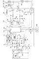
まず、図1を参照しつつ、負荷駆動装置100の構成に関して説明する。負荷駆動装置100は、マイコン10、電源制御部20、補機バッテリ電圧モニタ部31、予備バッテリ電圧モニタ部32、入出力回路40、ドライバ50に加えて、複数の回路素子を備えている。負荷駆動装置100は、複数の回路素子として、コンデンサC1、第1ダイオードD1〜第4ダイオードD4、第1スイッチング素子T1〜第5スイッチング素子T5、第1抵抗R1〜第5抵抗R5を備えている。マイコン10と電源制御部20は、特許請求の範囲における制御部に相当する。なお、複数の回路素子のうち第2抵抗R2〜第5抵抗R5、第1スイッチング素子T1〜第5スイッチング素子T5は、回路部EC1に相当する。
First, the configuration of the
なお、本実施形態では、一例として、通信インターフェイスであるCANインターフェイス60を備えた負荷駆動装置100を採用している。しかしながら、負荷駆動装置100は、CANインターフェイス60を備えていなくてもよい。図1においては、CANインターフェイスをCANI/Fと記載している。CANは、Controller Area Networkの略称である。CANは、登録商標である。
In the present embodiment, as an example, the
また、負荷駆動装置100は、外部装置との電気的な接続を行うための端子(ポート)が設けられている。具体的には、負荷駆動装置100は、第1電源端子P11、第2電源端子P12、IG端子P13、第1通信端子P14、第2通信端子P15、グランド端子P16、第1リレー端子P17、第2リレー端子P18、ロック端子P19、シフト端子P20などが設けられている。なお、以下においては、電気的な接続を単に接続とも記載する。
In addition, the
負荷駆動装置100は、上記端子などに、第1リレー210、第2リレー220、モータ300、補機バッテリ410、予備バッテリ装置420、他ノード600などが接続されている。また、負荷駆動装置100は、IG端子P13にイグニッションスイッチのオン及びオフに伴う電圧が印加される構成となっている。負荷駆動装置100は、IG端子P13にイグニッションスイッチのオンに伴う電圧が印加されると電源制御部20に起動信号が入力され、IG端子P13がイグニッションスイッチのオフに伴う電圧になると電源制御部20への起動信号の入力が停止する。
In the
なお、IGは、イグニッションの略称である。また、図3、図4におけるIGSWは、イグニッションスイッチの略称である。起動信号は、電源が供給されておらず停止状態のマイコン10及び電源制御部20を起動する信号である。また、起動信号は、IGSWによるものに限定されない。
IG is an abbreviation for ignition. IGSW in FIGS. 3 and 4 is an abbreviation for ignition switch. The activation signal is a signal for activating the
第1リレー210と第2リレー220は、負荷駆動装置100によって駆動される。つまり、負荷駆動装置100は、第1リレー210と第2リレー220を個別にオン及びオフする。第1リレー210は、ワイヤハーネスなどを介して第1リレー端子P17に接続されている。また、第1リレー210は、補機バッテリ410とモータ300との間に直列に接続されており、補機バッテリ410からモータ300への電源の供給、及び供給の停止を行うためのスイッチである。なお、オンは閉状態に相当する。オフは開状態に相当する。よって、オンオフは開閉に相当する。
The
一方、第2リレー220は、ワイヤハーネスなどを介して第2リレー端子P18に接続されている。また、第2リレー220は、予備バッテリ装置420とモータ300との間に直列に接続されており、予備バッテリ装置420からモータ300への電源の供給、及び供給の停止を行うためのスイッチである。
On the other hand, the
モータ300は、負荷に相当するものであり、パーキングロック機構のアクチュエータである。つまり、モータ300は、パーキングロック機構をロック状態とロック解除状態とに切り替える電動機である。モータ300は、例えば、三相交流電力によって動作する電動機を採用できる。モータ300は、補機バッテリ410と予備バッテリ装置420のいずれかから電源が供給され、負荷駆動装置100のU相端子、V相端子、W相端子と接続されている。
The
補機バッテリ410は、第1電源に相当し、負荷駆動装置100や、車両の他の補機に電源供給(例えば12Vを供給)するためのバッテリである。また、補機バッテリ410は、上記のようにモータ300に電源を供給可能に構成されている。補機バッテリ410は、+端子(プラス端子)が第1電源端子P11に接続され、−端子(マイナス端子)がグランド端子P16に接続されている。補機バッテリ410は、常時、負荷駆動装置100に電源を供給可能に構成されている。なお、補機バッテリ410は、負荷駆動装置100に対するメインのバッテリと言える。
The
予備バッテリ装置420は、第2電源に相当し、負荷駆動装置100とモータ300に電源を供給可能(例えば12Vを供給可能)に構成されたバッテリである。予備バッテリ装置420は、補機バッテリ410と異なり、負荷駆動装置100とモータ300以外の補機に電源を供給可能に構成されていない。なお、予備バッテリ装置420は、負荷駆動装置100とモータ300に専用に設けられていると言える。つまり、予備バッテリ装置420は、負荷駆動装置100とモータ300を含む負荷駆動システムに専用に設けられたバッテリと言える。ただし、予備バッテリ装置420は、負荷駆動システム専用とは限らない場合もある。
The
また、予備バッテリ装置420は、補機バッテリ410と異なり、常時、負荷駆動装置100に電源を供給するものではない。予備バッテリ装置420は、補機バッテリ410による電源供給が正常になされない場合に、補機バッテリ410にかわって負荷駆動装置100及びモータ300へ電源を供給するためのものであり、補機バッテリ410の予備として設けられている。このため、負荷駆動装置100は、自身への電源が失われることを抑制された構成となっている。また、負荷駆動装置100は、モータ300への電源供給が必要でありながら、電源供給ができない状況を抑制できる構成となっている。以下においては、電源供給を正常に行える状態を正常状態、電源供給を正常に行えない状態を異常状態とも称する。また、異常状態は、機能喪失とも言える。
Further, unlike the
この予備バッテリ装置420は、+端子が第2電源端子P12に接続され、−端子がグランド端子P16に接続されている。また、予備バッテリ装置420は、第1通信端子P14と第2通信端子P15に接続されている。さらに、予備バッテリ装置420は、スイッチ500を介して、補機バッテリ410の+端子と第1電源端子P11との配線に接続されており、補機バッテリ410から充電可能に構成されている。
The
予備バッテリ装置420は、補機バッテリ410と異なり、電池部に加えて、処理部や記憶部などを備えている。よって、予備バッテリ装置420は、予備バッテリASSYと言うこともできる。このため、予備バッテリ装置420は、補機バッテリ410の電圧をモニタ可能に構成されている。また、予備バッテリ装置420は、第1通信端子P14と第2通信端子P15を介して、負荷駆動装置100と双方向通信が可能に構成されている。
Unlike
予備バッテリ装置420は、例えば、予備バッテリ装置420が充電中であるか否か、予備バッテリ装置420の電圧、負荷駆動装置100に対して電源を供給可能か否か、電源制御部20への起動信号などを負荷駆動装置100に対して送信する。なお、負荷駆動装置100と予備バッテリ装置420との通信は、バッテリ通信とも言える。
For example, the
さらに、予備バッテリ装置420は、スイッチ500のオンとオフを制御可能に構成されている。このスイッチ500は、通常、オフとなっている。予備バッテリ装置420は、自身の充電が必要なときであり、且つ、補機バッテリ410が充電可能な状態のときに、スイッチ500をオフからオンに切り替える。なお、スイッチ500は、予備バッテリ装置420に内蔵されていてもよい。
Further, the
このように、予備バッテリ装置420は、通信機能、電圧モニタ機能、スイッチ制御機能などを備えていると言える。なお、補機バッテリ410は、予備バッテリ装置420と同様に、処理部や記憶部を備え、負荷駆動装置100との通信を行うように構成されていてもよい。
Thus, it can be said that the
他ノード600は、例えば、車室内に設けられたディスプレイや音声出力装置などの報知装置を採用できる。他ノード600は、負荷駆動装置100の通信端子に接続されている。
For example, the other node 600 may employ a notification device such as a display or an audio output device provided in the vehicle interior. The other node 600 is connected to the communication terminal of the
マイコン10は、電源制御部20、補機バッテリ電圧モニタ部31、予備バッテリ電圧モニタ部32、入出力回路40、ドライバ50、CANインターフェイス60と接続されている。また、マイコン10は、第1スイッチング素子T1、第2スイッチング素子T2、ロック端子P19、シフト端子P20と接続されている。マイコン10は、電源制御部20によって生成された電源(例えば5V)が供給される。なお、電源制御部20によって生成された電源は、負荷駆動装置100内で用いられる電源であり内部電源とも称する。
The
マイコン10は、演算処理装置と、プログラムやデータを記憶する記憶媒体などを備えている。記憶媒体は、演算処理装置によって読み取り可能なプログラムを非一時的に格納している。また、記憶媒体は、演算処理装置によって読み取り及び書き込み可能なデータを格納している。この記憶媒体は、半導体メモリまたは磁気ディスクなどによって提供されうる。マイコン10は、演算処理装置がデータを参照しつつ、プログラムを実行するなどして、後程説明する処理を行う。マイコン10は、例えば、第1リレー210と第2リレー220のオンオフを制御する。
The
なお、マイコン10は、アナログ‐デジタル変換回路(以下、AD回路)を備えている。また、マイコン10は、時間を計測するためにタイマの値を取得可能に構成されている。
The
マイコン10は、電源が供給されていない状態で、IG端子P13にIGSWのオンを示す電圧が印加されると、電源制御部20から内部電源が供給されて起動する。マイコン10は、起動すると、マイコン10への内部電源の供給を保持する信号を電源制御部20に対して送信する。これによって、マイコン10は、マイコン10への内部電源の供給を保持できる。なお、この信号は、5V要求信号や保持信号と言える。
When a voltage indicating ON of IGSW is applied to the IG terminal P13 in a state where no power is supplied, the
マイコン10は、駆動信号端子P1に第1スイッチング素子T1のベース端子が接続されており、許可信号端子P2に第2スイッチング素子T2のベース端子が接続されている。本実施形態では、第1スイッチング素子T1と第2スイッチング素子T2として、PNPトランジスタを採用している。
In the
マイコン10は、駆動信号端子P1から駆動信号としてLoとHiを個別に出力可能に構成されている。また、マイコン10は、許可信号端子P2から許可信号としてLoとHiを個別に出力可能に構成されている。なお、本実施形態では、後程説明する、第3スイッチング素子T3としてNPNトランジスタ、第4スイッチング素子T4と第5スイッチング素子T5としてMOSFETを採用している。しかしながら、各スイッチング素子T1〜T5は、これに限定されない。
The
なお、駆動信号は、第1リレー210の開閉を指示する開閉制御信号に相当し、駆動信号としてのLoが第1リレー210のオンを指示する信号であり、駆動信号としてのHiが第1リレー210のオフを指示する信号である。許可信号は、第2リレー220の開閉を指示する開閉制御信号に相当し、許可信号としてのLoが第2リレー220のオンを指示する信号であり、許可信号としてのHiが第2リレー220のオフを指示する信号である。
The drive signal corresponds to an open / close control signal for instructing opening / closing of the
また、第4スイッチング素子T4は、第1開閉スイッチに相当する。第5スイッチング素子T5は、第2開閉スイッチに相当する。第3スイッチング素子T3は、禁止スイッチに相当する。 The fourth switching element T4 corresponds to a first opening / closing switch. The fifth switching element T5 corresponds to a second opening / closing switch. The third switching element T3 corresponds to a prohibition switch.
さらに、マイコン10は、ロック端子P19からパーキングロック機構のロック状態を指示する信号(以下、ロック指示信号)が入力される。このロック指示信号は、例えば、ユーザによってパーキングスイッチなどが操作されることで出力される。
Further, the
また、マイコン10は、シフト端子P20からシフト切替を指示する信号が入力される。シフト切替を指示する信号は、Rレンジへのシフト切替を指示するRレンジ信号や、Dレンジへのシフト切替を指示するDレンジ信号などである。Rレンジ信号やDレンジ信号は、例えば、ユーザによってシフタなどが操作されることで出力される。Rレンジ信号やDレンジ信号は、パーキングロック機構のロック状態を解除するロック解除信号としても機能する。つまり、ロック解除信号は、ロック解除状態を指示する信号に相当する。
Further, the
マイコン10は、ロック指示信号が入力されると、モータ300を駆動してパーキングロック機構をロック状態とすることで、車両が走行できない状態とする。また、マイコン10は、パーキングロック機構がロック状態である場合に、ロック解除信号が入力されると、モータ300を駆動してパーキングロック機構のロック状態を解除することで、車両が走行できる状態とする。このため、負荷駆動装置100は、シフトバイワイヤ制御装置とも言える。さらに、負荷駆動システムは、シフトバイワイヤシステムとも言える。
When the lock instruction signal is input, the
なお、本実施形態では、ロック解除信号の一例として、Rレンジ信号やDレンジ信号を採用している。しかしながら、ロック解除信号はこれに限定されない。 In the present embodiment, an R range signal and a D range signal are employed as an example of the lock release signal. However, the lock release signal is not limited to this.
電源制御部20は、第1ダイオードD1を介して第1電源端子P11に接続され、且つ、第2ダイオードD2を介して第2電源端子P12に接続されている。よって、電源制御部20は、補機バッテリ410及び予備バッテリ装置420と接続可能に構成されている。電源制御部20は、第1ダイオードD1を介して補機バッテリ410から電源が供給可能であり、第2ダイオードD2を介して予備バッテリ装置420から電源が供給可能に構成されている。電源制御部20は、補機バッテリ410や予備バッテリ装置420から供給された電源から内部電源を生成する。
The
これにより、マイコン10は、補機バッテリ410が異常状態となった場合であっても、第2ダイオードD2を介した予備バッテリ装置420からの電源供給により、自身の電源を失うことなく動作可能となる。また、負荷駆動装置100は、補機バッテリ410が異常状態となった場合であっても、第2ダイオードD2を介した予備バッテリ装置420からの電源供給により、内部電源を得ることができると言える。
Thereby, even if the
第1ダイオードD1は、アノードが第1電源端子P11に接続されており、カソードが電源制御部20に接続されている。第2ダイオードD2は、アノードが第2電源端子P12に接続されており、カソードが電源制御部20に接続されている。なお、両ダイオードD1,D2のカソードと電源制御部20とを繋いでいる配線には、コンデンサC1の一端が接続されている。コンデンサC1の他端は、グランドに接続されている。
The first diode D1 has an anode connected to the first power supply terminal P11 and a cathode connected to the power
また、電源制御部20は、第1抵抗R1介してグランドに接続されている。電源制御部20は、第1抵抗R1との間の配線に、第3ダイオードD3を介してIG端子P13に接続され、且つ、第4ダイオードD4を介して第1通信端子P14に接続されている。第3ダイオードD3は、アノードがIG端子P13に接続されており、カソードが電源制御部20に接続されている。第4ダイオードD4は、アノードが第1通信端子P14に接続されており、カソードが電源制御部20に接続されている。よって、電源制御部20は、第3ダイオードD3を介して起動信号が入力されるとともに、第4ダイオードD4を介して起動信号が入力される構成となっている。
The power
また、電源制御部20は、IGSWがオンされたことで起動信号が入力された場合、マイコン10などに対して内部電源を供給可能に構成されている。さらに、電源制御部20は、IGSWのオンに伴う起動信号が入力された場合だけではなく、予備バッテリ装置420からの起動信号が入力された場合にも、マイコン10などに対して内部電源を供給可能に構成されている。このため、負荷駆動装置100は、内部電源を失陥してしまった場合であっても、予備バッテリ装置420からの起動信号によって、再起動が可能な構成となっている。
Moreover, the power
補機バッテリ電圧モニタ部31(以下、第1モニタ部31)は、補機バッテリ410の電圧をモニタし、モニタ結果をマイコン10に出力する。第1モニタ部31は、第1電源端子P11と第1ダイオードD1のアノードとの間の配線と、マイコン10のAD回路とに接続されている。予備バッテリ電圧モニタ部32(以下、第2モニタ部32)は、予備バッテリ装置420の電圧をモニタし、モニタ結果をマイコン10に出力する。第2モニタ部32は、第2電源端子P12と第2ダイオードD2のアノードとの間の配線と、マイコン10のAD回路とに接続されている。
The auxiliary battery voltage monitor unit 31 (hereinafter referred to as the first monitor unit 31) monitors the voltage of the
マイコン10は、第1モニタ部31からのモニタ結果によって補機バッテリ410の電圧をモニタできるとともに、第2モニタ部32からのモニタ結果によって予備バッテリ装置420の電圧をモニタできる。例えば、マイコン10は、第1モニタ部31からのモニタ結果(電圧)が閾値に達した場合、すなわち、第1モニタ部31からの電圧が閾値を下回った場合に異常状態であると判定する。また、マイコン10は、第1モニタ部31からの出力に基づいて、補機バッテリ410による電力供給の機能が喪失したか否かを判定すると言える。第1モニタ部31は、モニタ回路に相当する。
The
なお、ここでの閾値は、例えば0.1Vなど、補機バッテリ410が外れた場合や、補機バッテリ410と負荷駆動装置100とを繋いでいるコネクタが外れた場合に、とりうる電圧値を採用する。マイコン10は、予備バッテリ装置420に関しても同様に、異常状態であることを判定できる。
The threshold value here is, for example, 0.1 V, a voltage value that can be taken when the
また、マイコン10は、AD回路で電圧のモニタを行うため、各バッテリ410,420の機能喪失の兆候をつかむことができ、異常状態であることを即座に判断できる。つまり、マイコン10は、モニタ結果をデジタル値で取得する場合よりも、各バッテリ410,420の異常状態であることを早く判断できる。また、マイコン10は、各バッテリ410,420が正常状態であるか否かを即座に判断できるとも言える。さらに、マイコン10は、アナログ値で判断することにより、ノイズなどによるデジタル値の変動に対して、各バッテリ410,420が正常状態であるか否かの判断の信頼性を向上できる。
Further, since the
入出力回路40は、第1通信端子P14と第2通信端子P15とマイコン10に接続されている。入出力回路40は、予備バッテリ装置420とマイコン10との通信インターフェイスである。マイコン10と予備バッテリ装置420は、入出力回路40を介して双方向通信することができる。マイコン10は、例えば、電源供給の要求を予備バッテリ装置420へ送信する。マイコン10は、予備バッテリ装置420と通信できるため、予備バッテリ装置420が充電中であるか否か、電圧のモニタなどできる。
The input / output circuit 40 is connected to the first communication terminal P14, the second communication terminal P15, and the
ドライバ50は、マイコン10から出力された信号から、モータ300を駆動する駆動信号を生成するものである。そして、ドライバ50は、負荷駆動装置100のU相端子、V相端子、W相端子のそれぞれから、モータ300に対してU相駆動信号、V相駆動信号、W相駆動信号を出力する。つまり、マイコン10は、ドライバ50を介してモータ300を駆動すると言える。
The
CANインターフェイス60は、マイコン10がCANプロトコルに従って、他のノード600と通信を行うための通信インターフェイスである。なお、本実施形態では、通信インターフェイスの一例として、CANインターフェイス60を採用している。しかしながら、負荷駆動装置100は、これに限定されず、他ノード600と通信可能な構成であれば採用できる。
The
ここで、回路部EC1に関して説明する。つまり、マイコン10と第1リレー端子P17間の回路構成、及びマイコン10と第2リレー端子P18間の回路構成に関して説明する。本実施形態では、一例として以下に説明する回路構成を採用している。しかしながら、回路構成は、下記の構成に限定されない。
Here, the circuit unit EC1 will be described. That is, the circuit configuration between the
第1スイッチング素子T1は、ベース端子が駆動信号端子P1に接続されており、エミッタ端子が電源制御部20に接続されている。また、第1スイッチング素子T1は、コレクタ端子が第3抵抗R3を介してグランドに接続されており、且つ、第2抵抗R2を介して第4スイッチング素子T4のゲートに接続されている。
The first switching element T <b> 1 has a base terminal connected to the drive signal terminal P <b> 1 and an emitter terminal connected to the power
第2スイッチング素子T2は、ベース端子が許可信号端子P2に接続されており、エミッタ端子が電源制御部20に接続されている。また、第2スイッチング素子T2は、コレクタ端子が第5抵抗R5を介してグランドに接続されており、且つ、第4抵抗R4を介して第5スイッチング素子T5のゲートに接続されている。
The second switching element T2 has a base terminal connected to the permission signal terminal P2 and an emitter terminal connected to the power
第4スイッチング素子T4は、ドレイン端子が第1リレー端子P17に接続されており、ソース端子がグランドに接続されている。第4スイッチング素子T4は、マイコン10からの第1リレー210のオンオフを指示する開閉制御信号に応じて第1リレー210のオンオフ駆動を行う。
The fourth switching element T4 has a drain terminal connected to the first relay terminal P17 and a source terminal connected to the ground. The fourth switching element T4 performs on / off driving of the
一方、第5スイッチング素子T5は、ドレイン端子が第2リレー端子P18に接続されており、ソース端子がグランドに接続されている。第5スイッチング素子T5は、マイコン10からの第2リレー220のオンオフを指示する開閉制御信号に応じて第2リレー220のオンオフ駆動を行う。
On the other hand, the fifth switching element T5 has a drain terminal connected to the second relay terminal P18 and a source terminal connected to the ground. The fifth switching element T5 performs on / off driving of the
さらに、第2抵抗R2と第4スイッチング素子T4のゲートとの間、及び、第4抵抗R4と第5スイッチング素子T5のゲートとの間には、第3スイッチング素子T3が接続されている。第3スイッチング素子T3は、ベース端子が第2抵抗R2と第4スイッチング素子T4のゲートとの間に接続されており、コレクタ端子が第4抵抗R4と第5スイッチング素子T5のゲートとの間に接続されている。なお、第3スイッチング素子T3は、エミッタ端子がグランドに接続されている。 Further, a third switching element T3 is connected between the second resistor R2 and the gate of the fourth switching element T4 and between the fourth resistor R4 and the gate of the fifth switching element T5. The third switching element T3 has a base terminal connected between the second resistor R2 and the gate of the fourth switching element T4, and a collector terminal between the fourth resistor R4 and the gate of the fifth switching element T5. It is connected. The third switching element T3 has an emitter terminal connected to the ground.
第3スイッチング素子T3は、補機バッテリ410から第1リレー210を介してモータ300への電源供給を行うために、マイコン10から駆動信号としてLoが出力されている場合、第5スイッチング素子T5による第2リレー220のオン駆動を禁止する。具体的には、第3スイッチング素子T3は、マイコン10から駆動信号としてLoが出力されると、第5スイッチング素子T5のゲート端子の電位を接地して、第5スイッチング素子T5による第2リレー220のオン駆動を禁止する。このように、負荷駆動装置100は、トランジスタである第3スイッチング素子T3で、MOSFETである第5スイッチング素子T5のゲート電位を接地することで、第5スイッチング素子T5の動作を停止できる構成となっている。
The third switching element T3 is driven by the fifth switching element T5 when Lo is output as a drive signal from the
ここで、図2、図3を参照しつつ、負荷駆動装置100の動作に関して説明する。
Here, the operation of the
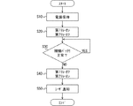
マイコン10は、内部電源の供給が開始されると図3のフローチャートに示す処理を開始する。
The
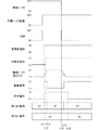
ステップS10では、電源保持を行う。マイコン10は、図3のタイミングt11に示すように電源制御部20から内部電源が供給されると、タイミングt12に示すように電源制御部20に対して5V要求信号を出力して、自身への内部電源の供給を保持する。つまり、負荷駆動装置100は、IGSWがオフからオンに切り替わることにより、電源制御部20が内部電源を生成してマイコン10へ供給することで動作可能となる。また、IGSWのオン後、予備バッテリ装置420は、負荷駆動装置100へ電源供給を行う。
In step S10, power is held. When the internal power is supplied from the power
ステップS20では、第1リレーをオンするとともに、第2リレーをオフする。マイコン10は、図3のタイミングt13に示すように、駆動信号をLo出力することで、第1リレー210をオフからオンに切り替える。このとき、マイコン10は、許可信号をHi出力することで、第2リレー220をオフのままとする。つまり、マイコン10は、第1リレー210をオンにしつつ、第2リレー220をオンせずにオフとする。負荷駆動装置100は、補機バッテリ410が正常状態の場合、つまり、通常時、第1リレー210を介してモータ300へ電源供給を行う。なお、負荷駆動装置100は、第1リレー210を介してモータ300へ電源供給を行っている場合、ロック指示信号が入力されると、マイコン10がモータ300を駆動してパーキングロック機構をロック状態とする。
In step S20, the first relay is turned on and the second relay is turned off. The
ステップS30では、補機バッテリが正常であるか否かを判定する。マイコン10は、第1モニタ部31のモニタ結果に基づいて、補機バッテリ410が正常状態であるか否かを判定する。そして、マイコン10は、補機バッテリ410が正常状態であると判定した場合はステップS30を繰り返し実行し、補機バッテリ410が正常状態でないと判定した場合はステップS40へ進む。
In step S30, it is determined whether or not the auxiliary battery is normal. The
例えば、図3のタイミングチャートでは、タイミングt14で補機バッテリ410に失陥が生じた例を採用している。この場合、マイコン10は、タイミングt13からタイミングt15に達するまでの間、補機バッテリ410が正常状態であると判定する。そして、マイコン10は、第1モニタ部31からの電圧が閾値を下回ったタイミングt15で、補機バッテリ410が正常状態でないと判定する。
For example, the timing chart of FIG. 3 employs an example in which a failure occurs in the
ステップS40では、第1リレーをオフするとともに、第2リレーをオンする。マイコン10は、図3のタイミングt15に示すように、駆動信号をHi出力することで、第1リレー210をオンからオフに切り替える。つまり、マイコン10は、補機バッテリ410による電力供給の機能が喪失した場合、駆動信号をHi出力することで第1リレー210を開状態とするとともに第3スイッチング素子T3による禁止を解除する。
In step S40, the first relay is turned off and the second relay is turned on. The
そして、マイコン10は、図3のタイミングt16に示すように、許可信号をLo出力することで、第2リレー220をオフからオンに切り替える。つまり、マイコン10は、補機バッテリ410にかえて予備バッテリ装置420から第2リレー220を介してモータ300への電力供給を行うために、許可信号をLo出力する。このように、負荷駆動装置100は、補機バッテリ410による電力供給の機能が喪失した場合であっても、予備バッテリ装置420から電力供給を行わせるため、モータ300が駆動可能な状態を継続できる。
And the
また、マイコン10は、第1リレー210と第2リレー220とが同時にオンすることを避けるために、第1リレー210がオフになるのを待ってから、第2リレー220をオンにする。駆動信号がLoからHiに切り替わってから第1リレー210がオフに切り替わる時間(以下、オフ時間)は予めわかっている。このため、マイコン10は、取得したタイマの値などを用いて、駆動信号をHi出力してからの時間を計測する。そして、マイコン10は、計測した時間がオフ時間を超えたことを確認して、第2リレー220をオフからオンにする。これによって、負荷駆動装置100は、第1リレー210と第2リレー220とが同時にオンすることを抑制できる。
In addition, the
このように、負荷駆動装置100は、補機バッテリ410が異常状態となっても、補機バッテリ410及び第1リレー210のかわりに、予備バッテリ装置420から第2リレー220を介してモータ300へ電源供給を行うことができる。このため、負荷駆動装置100は、第2リレー220を介してモータ300へ電源供給を行っている場合、ロック指示信号が入力されると、マイコン10がモータ300を駆動してパーキングロック機構をロック状態とする。このように、負荷駆動装置100は、補機バッテリ410が異常状態となった場合であっても、パーキングロック機構をロック状態とすることができる。つまり、負荷駆動装置100は、補機バッテリ410が異常状態となった場合であっても、車両を停車させることができる。よって、第2リレー220は、予備のリレーと言える。
Thus, even if the
ステップS50では、ユーザに通知する。マイコン10は、補機バッテリ410が異常状態であることをユーザに通知する。このとき、マイコン10は、例えばCANI/F60を介して、他ノード600のディスプレイを用いて通知を行う。しかしながら、本発明は、ステップS50を行わなくてもよいし、ステップS50として他の処理を行ってもよい。
In step S50, the user is notified. The
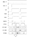
次に、図4を参照しつつ、同時オン発生時における負荷駆動装置100の動作に関して説明する。負荷駆動装置100は、図4のタイミングt17に示すように、第1リレー210のオン後、第1リレー210のかわりに第2リレー220をオンさせるために、駆動信号をHi出力しようとした場合に、駆動信号がLo固着することが起こりうる。この場合、負荷駆動装置100は、図4のタイミングt18に示すように許可信号をLo出力して第2スイッチング素子T2がオンとなる。つまり、負荷駆動装置100は、図4のタイミングt18〜t19に示すように、駆動信号と許可信号の両方が同時にLo出力となる。
Next, the operation of the
ところが、負荷駆動装置100は、駆動信号と許可信号の両方がLo出力となった後も、駆動信号によって第3スイッチング素子T3をオンさせることができる。このため、負荷駆動装置100は、第3スイッチング素子T3をオンさせることで、第5スイッチング素子T5のゲート電圧レベルをグランドレベルとすることができる。従って、負荷駆動装置100は、第2リレー220のオフを継続させることができる。
However, the
この場合、負荷駆動装置100は、本来であれば第2リレー220がオンすべきタイミングで、第2リレー220のオフが継続しており、且つ、第1リレー210がオン継続していることを検知して、ユーザへ異常通知してもよい。ユーザへの異常通知としては、車両の再起動、すなわちIGSWを一旦オフした後に再度IGSWをオンさせることを促す内容を含んでいると好ましい。負荷駆動装置100は、リセット再起動され、正常復帰する可能性がある。
In this case, the
なお、負荷駆動装置100は、ドライバ50と接続されるポートに、各リレー210,220がオン及びオフした際に、電圧が供給される。負荷駆動装置100は、この電圧がドライバ50と接続されるポートに供給されているかどうかで、各リレー210,220のオン及びオフを検知できる。上記例の場合、負荷駆動装置100は、第1リレー210がオフするはずが、オフできずに電圧が連続的に供給されてしまうため、第1リレー210のオン継続を検知できる。
The
なお、負荷駆動装置100は、補機バッテリ410が異常状態となった場合だけでなく、動作確認のために第2リレー220をオンさせることがある。また、駆動信号のLo固着は、第1スイッチング素子T1のオン故障とも言える。
Note that the
このように、負荷駆動装置100は、第1リレー210のオンを指示する開閉制御信号が出力されている場合に、第2リレー220のオンを禁止する第3スイッチング素子T3を備えている。このため、負荷駆動装置100は、第1リレー210と第2リレー220の両方が同時にオンとなることを抑制できる。また、負荷駆動装置100は、第1リレー210と第2リレー220の上流に接続されたダイオードなどを備えることなく両リレー210,220が同時にオンとなることを抑制できるため、ポートの数及びワイヤハーネスの本数が増加することを抑制できる。負荷駆動装置100は、ワイヤハーネスの本数が増加することを抑制できるため、ワイヤハーネスの増加に伴う車両重量の増加を抑制できる、さらに、コストアップを抑制できる。
As described above, the
また、負荷駆動装置100は、両リレー210,220が同時にオンした場合、補機バッテリ410と予備バッテリ装置420間が短絡することが考えられる。しかしながら、負荷駆動装置100は、両リレー210,220が同時にオンすることを抑制できるため、補機バッテリ410と予備バッテリ装置420間が短絡することを抑制できる。
Further, in the
負荷駆動装置100は、補機バッテリ410と予備バッテリ装置420間が短絡した状態で、補機バッテリ410がグランドショートした場合、両リレー210,220を介して予備バッテリ装置420からも電流が流れてしまうことがある。この場合、負荷駆動装置100は、モータ300へ供給する電源を失ってしまう可能性がある。しかしながら、負荷駆動装置100は、両リレー210,220が同時にオンすることを抑制できるため、モータ300へ供給する電源を失うことを抑制できる。
In the
さらに、負荷駆動装置100は、特許文献1のように、ダイオードを増やす必要がないため、ダイオードのために配線を増やす必要がなく、電圧ドロップを抑制できる。このため、負荷駆動装置100は、電圧ドロップによって駆動可能な電圧範囲が狭くなることを防ぐことができる。つまり、負荷駆動装置100は、ダイオードを用いることにより駆動可能な電圧範囲が狭くなるという特許文献1の課題を解決することができる。
Furthermore, since the
以上、本発明の好ましい実施形態について説明した。しかしながら、本発明は、上記実施形態に何ら制限されることはなく、本発明の趣旨を逸脱しない範囲において、種々の変形が可能である。 The preferred embodiments of the present invention have been described above. However, the present invention is not limited to the above embodiment, and various modifications can be made without departing from the spirit of the present invention.
10…マイコン、20…電源制御部、31…補機バッテリ電圧モニタ部、32…予備バッテリ電圧モニタ部、40…入出力回路、50…ドライバ、60…CANインターフェイス、C1…コンデンサ、D1…第1ダイオード、D2…第2ダイオード、D3…第3ダイオード、D4…第4ダイオード、T1…第1スイッチング素子、T2…第2スイッチング素子、T3…第3スイッチング素子、T4…第4スイッチング素子、T5…第5スイッチング素子、R1…第1抵抗、R2…第2抵抗、R3…第3抵抗、R4…第4抵抗、R5…第5抵抗、EC1…回路部、100…負荷駆動装置、210…第1リレー、220…第2リレー、300…モータ、410…補機バッテリ、420…予備バッテリ、500…スイッチ、600…他ノード
DESCRIPTION OF
Claims (9)
前記第1リレーと前記第2リレーの開閉を制御する制御部(10、20)と、
前記制御部からの前記第1リレーの開閉を指示する開閉制御信号に応じて前記第1リレーの開閉駆動を行う第1開閉スイッチ(T4)と、
前記制御部からの前記第2リレーの開閉を指示する開閉制御信号に応じて前記第2リレーの開閉駆動を行う第2開閉スイッチ(T5)と、
前記第1電源から前記第1リレーを介して前記負荷への電力供給を行うために、前記制御部から前記第1リレーの閉状態を指示する前記開閉制御信号が出力されている場合、前記第2開閉スイッチによる前記第2リレーの閉駆動を禁止する禁止スイッチ(T3)と、を備えている負荷駆動装置。 A first relay (210) is provided between the first power source (410) and the load (300), and a second relay (220) is provided between the second power source (420) and the load. A load driving device for driving the load capable of supplying power from either one power source or the second power source,
A control unit (10, 20) for controlling opening and closing of the first relay and the second relay;
A first opening / closing switch (T4) for opening / closing the first relay in response to an opening / closing control signal for instructing opening / closing of the first relay from the control unit;
A second opening / closing switch (T5) for opening / closing the second relay in response to an opening / closing control signal for instructing opening / closing of the second relay from the control unit;
In order to supply power from the first power source to the load via the first relay, the control unit outputs the opening / closing control signal instructing the closed state of the first relay. And a prohibition switch (T3) for prohibiting the second relay from being closed by the two opening / closing switches.
前記制御部は、前記モニタ回路からの出力に基づいて、前記第1電源による電力供給の機能が喪失したか否かを判定する請求項3に記載の負荷駆動装置。 A monitor circuit (31) for monitoring the voltage of the first power supply;
4. The load driving device according to claim 3, wherein the control unit determines whether or not a function of power supply by the first power source has been lost based on an output from the monitor circuit. 5.
前記制御部は、停止状態時に、前記第2電源との通信によって前記起動信号が入力されると起動する請求項6に記載の負荷駆動装置。 The second power source is capable of outputting a start signal for starting the control unit in a stopped state when power is not supplied.
The load driving device according to claim 6, wherein the control unit is activated when the activation signal is input by communication with the second power source in a stopped state.
前記禁止スイッチは、前記制御部から前記第1リレーの閉状態を指示する前記開閉制御信号が出力されると、前記ゲート端子の電位を接地して、前記MOSFETによる前記第2リレーの閉駆動を禁止するトランジスタである請求項1乃至4のいずれか一項に記載の負荷駆動装置。 The second open / close switch is a MOSFET that is driven by a signal input to a gate terminal,
When the opening / closing control signal instructing the closed state of the first relay is output from the control unit, the prohibition switch grounds the potential of the gate terminal and causes the MOSFET to drive the second relay to close. 5. The load driving device according to claim 1, wherein the load driving device is a transistor to be prohibited.
前記制御部は、前記第1リレーと前記第2リレーのいずれか一方を閉状態として、前記電動機に電力供給を行っているときに、前記ロック状態と前記ロック解除状態を指示する指示信号を前記電動機に対して出力する請求項1乃至8のいずれか一項に記載の負荷駆動装置。 The load is an electric motor that switches a parking lock mechanism in a vehicle between a locked state and an unlocked state,
The control unit is configured to provide an instruction signal for instructing the locked state and the unlocked state when one of the first relay and the second relay is closed and power is supplied to the electric motor. The load driving device according to any one of claims 1 to 8, wherein the load driving device outputs to an electric motor.
Priority Applications (2)
| Application Number | Priority Date | Filing Date | Title |
|---|---|---|---|
| JP2016251787A JP6805810B2 (en) | 2016-12-26 | 2016-12-26 | Load drive |
| US15/826,782 US10340106B2 (en) | 2016-12-26 | 2017-11-30 | Load driver |
Applications Claiming Priority (1)
| Application Number | Priority Date | Filing Date | Title |
|---|---|---|---|
| JP2016251787A JP6805810B2 (en) | 2016-12-26 | 2016-12-26 | Load drive |
Publications (2)
| Publication Number | Publication Date |
|---|---|
| JP2018106902A true JP2018106902A (en) | 2018-07-05 |
| JP6805810B2 JP6805810B2 (en) | 2020-12-23 |
Family
ID=62629925
Family Applications (1)
| Application Number | Title | Priority Date | Filing Date |
|---|---|---|---|
| JP2016251787A Active JP6805810B2 (en) | 2016-12-26 | 2016-12-26 | Load drive |
Country Status (2)
| Country | Link |
|---|---|
| US (1) | US10340106B2 (en) |
| JP (1) | JP6805810B2 (en) |
Cited By (1)
| Publication number | Priority date | Publication date | Assignee | Title |
|---|---|---|---|---|
| JP2021142964A (en) * | 2020-03-13 | 2021-09-24 | 日立Astemo株式会社 | On-vehicle control device |
Families Citing this family (6)
| Publication number | Priority date | Publication date | Assignee | Title |
|---|---|---|---|---|
| US12491943B1 (en) | 2013-03-10 | 2025-12-09 | Oshkosh Defense, Llc | Systems and methods for a military vehicle |
| US11427143B1 (en) * | 2017-04-28 | 2022-08-30 | Oshkosh Defense, Llc | Electrical load management in a vehicle |
| US9303715B2 (en) | 2013-03-10 | 2016-04-05 | Oshkosh Defense, Llc | Limiting system for a vehicle suspension component |
| DE112017002648T5 (en) * | 2016-05-26 | 2019-03-14 | Hitachi Automotive Systems, Ltd. | Brake system and vehicle |
| JP7232068B2 (en) * | 2019-02-07 | 2023-03-02 | 株式会社Subaru | power supply system |
| JP7529988B2 (en) * | 2020-11-20 | 2024-08-07 | 株式会社デンソーウェーブ | Industrial Control Output Module |
Citations (6)
| Publication number | Priority date | Publication date | Assignee | Title |
|---|---|---|---|---|
| JPH04253418A (en) * | 1991-01-29 | 1992-09-09 | Nec Corp | Semiconductor device |
| JP2002313170A (en) * | 2001-04-10 | 2002-10-25 | Kyoto Denkiki Kk | Switching device |
| JP2011155829A (en) * | 2009-12-28 | 2011-08-11 | Sanyo Electric Co Ltd | Battery system and electric vehicle including the same |
| JP2012072854A (en) * | 2010-09-29 | 2012-04-12 | Aisin Aw Co Ltd | Electric actuator for parking lock |
| US20140312685A1 (en) * | 2012-01-12 | 2014-10-23 | Allison Transmission, Inc. | System and method for high voltage cable detection in hybrid vehicles |
| JP2015217734A (en) * | 2014-05-15 | 2015-12-07 | 株式会社オートネットワーク技術研究所 | Power source device of automobile |
Family Cites Families (6)
| Publication number | Priority date | Publication date | Assignee | Title |
|---|---|---|---|---|
| US2728865A (en) * | 1951-11-05 | 1955-12-27 | Walter T J Day | Automatic power control system |
| US5487278A (en) * | 1994-05-06 | 1996-01-30 | Kenneth J. Hartman | Back-up switching system for refrigerator trucks |
| JP2002075622A (en) | 2000-09-04 | 2002-03-15 | Fuji Electric Co Ltd | Electromagnetic cooker power supply |
| US6330176B1 (en) * | 2000-11-15 | 2001-12-11 | Powerware Corporation | Multi-input power transfer and uninterruptible power supply apparatus and methods of operation thereof |
| JP4482462B2 (en) | 2005-01-14 | 2010-06-16 | 矢崎総業株式会社 | Simultaneous ON prevention circuit in relay drive |
| JP5390339B2 (en) | 2009-10-29 | 2014-01-15 | 株式会社東芝 | Landry equipment |
-
2016
- 2016-12-26 JP JP2016251787A patent/JP6805810B2/en active Active
-
2017
- 2017-11-30 US US15/826,782 patent/US10340106B2/en active Active
Patent Citations (6)
| Publication number | Priority date | Publication date | Assignee | Title |
|---|---|---|---|---|
| JPH04253418A (en) * | 1991-01-29 | 1992-09-09 | Nec Corp | Semiconductor device |
| JP2002313170A (en) * | 2001-04-10 | 2002-10-25 | Kyoto Denkiki Kk | Switching device |
| JP2011155829A (en) * | 2009-12-28 | 2011-08-11 | Sanyo Electric Co Ltd | Battery system and electric vehicle including the same |
| JP2012072854A (en) * | 2010-09-29 | 2012-04-12 | Aisin Aw Co Ltd | Electric actuator for parking lock |
| US20140312685A1 (en) * | 2012-01-12 | 2014-10-23 | Allison Transmission, Inc. | System and method for high voltage cable detection in hybrid vehicles |
| JP2015217734A (en) * | 2014-05-15 | 2015-12-07 | 株式会社オートネットワーク技術研究所 | Power source device of automobile |
Cited By (2)
| Publication number | Priority date | Publication date | Assignee | Title |
|---|---|---|---|---|
| JP2021142964A (en) * | 2020-03-13 | 2021-09-24 | 日立Astemo株式会社 | On-vehicle control device |
| JP7212641B2 (en) | 2020-03-13 | 2023-01-25 | 日立Astemo株式会社 | In-vehicle control device |
Also Published As
| Publication number | Publication date |
|---|---|
| US10340106B2 (en) | 2019-07-02 |
| US20180182583A1 (en) | 2018-06-28 |
| JP6805810B2 (en) | 2020-12-23 |
Similar Documents
| Publication | Publication Date | Title |
|---|---|---|
| JP6805810B2 (en) | Load drive | |
| JP6610456B2 (en) | Backup power supply and backup system | |
| JP5240260B2 (en) | Electronic control device for vehicle | |
| JP6583610B2 (en) | Fault diagnosis device for vehicle charging system | |
| US7813849B2 (en) | Vehicle control system | |
| WO2008035503A1 (en) | Device and method for controlling electric power source for hybrid vehicle | |
| US8760001B2 (en) | Supplying circuit for the electrical supply of a vehicle | |
| JP2020078150A (en) | Charging device | |
| JP2019087917A (en) | Control device | |
| JP2022082221A (en) | In-vehicle charger and in-vehicle charging system | |
| CN114450197A (en) | Electronic control device | |
| JP2012205314A (en) | Vehicle control system | |
| US20120150382A1 (en) | Starter relay structure for auto-starting | |
| JP2008253048A (en) | Vehicle start control device | |
| US10845429B2 (en) | Electronic control device | |
| JP6773192B2 (en) | Backup power supply and backup system | |
| JP6597456B2 (en) | Electronic control unit | |
| US9803608B2 (en) | Apparatus and method for vehicle voltage stabilization | |
| JP5764043B2 (en) | Vehicle control system | |
| JP2020204410A (en) | Backup power source device and backup system | |
| US11299115B2 (en) | Power storage unit control device | |
| JP4239949B2 (en) | Hybrid control system | |
| US7839014B2 (en) | Pulse-width modulation rectifier having an emergency generator operating mode | |
| JP7489304B2 (en) | Electronic Control Unit | |
| JP2013183591A (en) | Charge/discharge control method for vehicle, charge/discharge controller in vehicle, and vehicle power supply device |
Legal Events
| Date | Code | Title | Description |
|---|---|---|---|
| A621 | Written request for application examination |
Free format text: JAPANESE INTERMEDIATE CODE: A621 Effective date: 20190315 |
|
| A977 | Report on retrieval |
Free format text: JAPANESE INTERMEDIATE CODE: A971007 Effective date: 20191205 |
|
| A131 | Notification of reasons for refusal |
Free format text: JAPANESE INTERMEDIATE CODE: A131 Effective date: 20200121 |
|
| A521 | Request for written amendment filed |
Free format text: JAPANESE INTERMEDIATE CODE: A523 Effective date: 20200319 |
|
| A131 | Notification of reasons for refusal |
Free format text: JAPANESE INTERMEDIATE CODE: A131 Effective date: 20200630 |
|
| A521 | Request for written amendment filed |
Free format text: JAPANESE INTERMEDIATE CODE: A523 Effective date: 20200825 |
|
| TRDD | Decision of grant or rejection written | ||
| A01 | Written decision to grant a patent or to grant a registration (utility model) |
Free format text: JAPANESE INTERMEDIATE CODE: A01 Effective date: 20201104 |
|
| A61 | First payment of annual fees (during grant procedure) |
Free format text: JAPANESE INTERMEDIATE CODE: A61 Effective date: 20201117 |
|
| R151 | Written notification of patent or utility model registration |
Ref document number: 6805810 Country of ref document: JP Free format text: JAPANESE INTERMEDIATE CODE: R151 |
|
| R250 | Receipt of annual fees |
Free format text: JAPANESE INTERMEDIATE CODE: R250 |
|
| R250 | Receipt of annual fees |
Free format text: JAPANESE INTERMEDIATE CODE: R250 |
|
| R250 | Receipt of annual fees |
Free format text: JAPANESE INTERMEDIATE CODE: R250 |