JP2018100665A - Hermetic compressor - Google Patents
Hermetic compressor Download PDFInfo
- Publication number
- JP2018100665A JP2018100665A JP2017235766A JP2017235766A JP2018100665A JP 2018100665 A JP2018100665 A JP 2018100665A JP 2017235766 A JP2017235766 A JP 2017235766A JP 2017235766 A JP2017235766 A JP 2017235766A JP 2018100665 A JP2018100665 A JP 2018100665A
- Authority
- JP
- Japan
- Prior art keywords
- expansion chamber
- fluid expansion
- hermetic
- hermetic compressor
- housing
- Prior art date
- Legal status (The legal status is an assumption and is not a legal conclusion. Google has not performed a legal analysis and makes no representation as to the accuracy of the status listed.)
- Pending
Links
Images


Classifications
-
- F—MECHANICAL ENGINEERING; LIGHTING; HEATING; WEAPONS; BLASTING
- F04—POSITIVE - DISPLACEMENT MACHINES FOR LIQUIDS; PUMPS FOR LIQUIDS OR ELASTIC FLUIDS
- F04B—POSITIVE-DISPLACEMENT MACHINES FOR LIQUIDS; PUMPS
- F04B39/00—Component parts, details, or accessories, of pumps or pumping systems specially adapted for elastic fluids, not otherwise provided for in, or of interest apart from, groups F04B25/00 - F04B37/00
- F04B39/0027—Pulsation and noise damping means
- F04B39/0055—Pulsation and noise damping means with a special shape of fluid passage, e.g. bends, throttles, diameter changes, pipes
- F04B39/0061—Pulsation and noise damping means with a special shape of fluid passage, e.g. bends, throttles, diameter changes, pipes using muffler volumes
-
- F—MECHANICAL ENGINEERING; LIGHTING; HEATING; WEAPONS; BLASTING
- F04—POSITIVE - DISPLACEMENT MACHINES FOR LIQUIDS; PUMPS FOR LIQUIDS OR ELASTIC FLUIDS
- F04B—POSITIVE-DISPLACEMENT MACHINES FOR LIQUIDS; PUMPS
- F04B39/00—Component parts, details, or accessories, of pumps or pumping systems specially adapted for elastic fluids, not otherwise provided for in, or of interest apart from, groups F04B25/00 - F04B37/00
- F04B39/12—Casings; Cylinders; Cylinder heads; Fluid connections
- F04B39/121—Casings
-
- F—MECHANICAL ENGINEERING; LIGHTING; HEATING; WEAPONS; BLASTING
- F04—POSITIVE - DISPLACEMENT MACHINES FOR LIQUIDS; PUMPS FOR LIQUIDS OR ELASTIC FLUIDS
- F04B—POSITIVE-DISPLACEMENT MACHINES FOR LIQUIDS; PUMPS
- F04B39/00—Component parts, details, or accessories, of pumps or pumping systems specially adapted for elastic fluids, not otherwise provided for in, or of interest apart from, groups F04B25/00 - F04B37/00
- F04B39/0027—Pulsation and noise damping means
- F04B39/0055—Pulsation and noise damping means with a special shape of fluid passage, e.g. bends, throttles, diameter changes, pipes
- F04B39/0072—Pulsation and noise damping means with a special shape of fluid passage, e.g. bends, throttles, diameter changes, pipes characterised by assembly or mounting
-
- F—MECHANICAL ENGINEERING; LIGHTING; HEATING; WEAPONS; BLASTING
- F04—POSITIVE - DISPLACEMENT MACHINES FOR LIQUIDS; PUMPS FOR LIQUIDS OR ELASTIC FLUIDS
- F04B—POSITIVE-DISPLACEMENT MACHINES FOR LIQUIDS; PUMPS
- F04B39/00—Component parts, details, or accessories, of pumps or pumping systems specially adapted for elastic fluids, not otherwise provided for in, or of interest apart from, groups F04B25/00 - F04B37/00
- F04B39/12—Casings; Cylinders; Cylinder heads; Fluid connections
- F04B39/123—Fluid connections
Abstract
Description
本発明は密閉圧縮機に関し、より詳細には、少なくとも1つの流体膨張チャンバ、つまり吐出ライン(吐出マフラー)または吸引ライン(吸引マフラー)内で使用可能な脈動減衰チャンバが設けられた、密閉圧縮機に関する。 The present invention relates to a hermetic compressor, and more particularly to a hermetic compressor provided with at least one fluid expansion chamber, ie a pulsation damping chamber that can be used in a discharge line (discharge muffler) or a suction line (suction muffler). About.
本発明によれば、本明細書で開示される密閉圧縮機は、気密筐体および少なくとも1つの付加的な壁部を備えることで区別され、気密筐体と付加的な壁部との間に画定された容積は、最終的に前記流体膨張チャンバを画定する。 According to the present invention, the hermetic compressor disclosed herein is distinguished by comprising an airtight housing and at least one additional wall, and between the airtight housing and the additional wall. The defined volume ultimately defines the fluid expansion chamber.
当業者にとって周知のように、密閉圧縮機、特に容積式圧縮機構は、構成要素の中でもとりわけ、吐出膨張チャンバ(「吐出マフラー」とも称される)および吸引膨張チャンバ(「吸引マフラー」とも称される)を含む。一般的な方式において、流体膨張チャンバは有効な流体の脈動を減衰する一般的な機能を有するが、つまり流体膨張チャンバの受動的動作が支配する機能原理は音響学の専門家および理論家に広く知られており、さらに専門技術文献特に詳述されている。 As is well known to those skilled in the art, hermetic compressors, particularly positive displacement compression mechanisms, are also referred to as discharge expansion chambers (also referred to as “discharge mufflers”) and suction expansion chambers (also referred to as “suction mufflers”), among other components. Included). In a general manner, the fluid expansion chamber has the general function of attenuating effective fluid pulsations, but the functional principle governed by the passive operation of the fluid expansion chamber is widely known to acoustic experts and theorists. Known and further detailed in the technical literature.
現在の先端技術は、密閉圧縮機で使用される流体膨張チャンバの無限のモデルおよび構成を備える。 Current advanced technology comprises an endless model and configuration of fluid expansion chambers used in hermetic compressors.
たとえば、吐出膨張チャンバの容積が、密閉圧縮機の気密筐体の中に非固定的に配置された中空モジュール体によって画定される構成がある。圧縮機構ヘッド、中空モジュール体、および吐出ダクトの間の流体連通は、剛性金属管によって行われる。 For example, in some configurations, the volume of the discharge expansion chamber is defined by a hollow module body that is non-fixedly disposed within the hermetic housing of the hermetic compressor. Fluid communication between the compression mechanism head, the hollow module body, and the discharge duct is performed by a rigid metal tube.
たとえば、吐出膨張チャンバの容積が、圧縮機ブロック自体の中で完全にまたは部分的に画定される構成がある。圧縮機構ヘッド、圧縮機ブロック、および吐出ダクトの間の流体連通は、剛性金属管によって行われる。 For example, there are configurations in which the volume of the discharge expansion chamber is completely or partially defined within the compressor block itself. Fluid communication between the compression mechanism head, the compressor block, and the discharge duct is provided by a rigid metal tube.
たとえば、米国特許第4782858号明細書に説明されるように、吐出膨張チャンバの容積が圧縮機構ヘッドのキャップ内で完全に画定される構成がある。圧縮機構ヘッドと吐出ダクトとの間の流体連通は、剛性金属管によって行われる。 For example, as described in US Pat. No. 4,782,858, there is a configuration in which the volume of the discharge expansion chamber is completely defined within the cap of the compression mechanism head. Fluid communication between the compression mechanism head and the discharge duct is effected by a rigid metal tube.
たとえば、米国特許出願公開第2009/162215号明細書に説明されるように、吐出膨張チャンバの容積が、ヘッドのキャップ内で完全に画定される第一の「副容積」、およびヘッドのキャップと圧縮シリンダブロックのセグメントの外面との間で画定される第二の「副容積」の2つに分割される構成があり、2つの「副容積」間の流体連通は、シリンダブロックの全体的構造を変更することなく、その配置内で画定される。圧縮機構ヘッドと吐出ダクトとの間の流体連通は、剛性金属管によって行われる。 For example, as described in U.S. Patent Application Publication No. 2009/162215, the volume of the discharge expansion chamber is defined as a first “subvolume” that is completely defined within the cap of the head, and the cap of the head; There is a configuration divided into two "secondary volumes" defined between the outer surfaces of the segments of the compression cylinder block and the fluid communication between the two "secondary volumes" is the overall structure of the cylinder block Is defined within the arrangement without modification. Fluid communication between the compression mechanism head and the discharge duct is effected by a rigid metal tube.
しかしながら、周知の膨張チャンバのモデルまたは構成にかかわらず、これらは常に圧縮機の気密筐体の中に配置されており、つまりこれらは、その有効容積がその他の構成要素およびシステムの中でも電動モータなどの圧縮機構、とりわけ圧縮機ブロックと共有される内部環境に、配置されることに留意される。 However, regardless of the well-known expansion chamber model or configuration, they are always placed in the compressor's hermetic enclosure, i.e. they have an effective volume such as an electric motor among other components and systems. It is noted that it is located in an internal environment that is shared with other compression mechanisms, particularly the compressor block.
一般的には、膨張チャンバが気密筐体内に配置されるという事実は3つの不都合を生じるが、そのうちの1つは熱的観点から、もう1つは寸法的観点から、3つ目は信頼性の状況に関するものである。 In general, the fact that the expansion chamber is placed in an airtight enclosure causes three disadvantages, one of which is from a thermal point of view and one from a dimensional point of view, and the third is reliability. Is related to the situation.
熱的観点に関して、吐出膨張チャンバは、温度が吐出流体の温度よりも低い、つまり吐出膨張チャンバの外部の温度が内部の温度よりも低い環境内(気密筐体内)に配置されることに、留意される。結果的に、圧縮機の筐体の内部環境(吸引流体)は厳しい熱交換を受けることになり、その温度は吐出膨張チャンバを通じて循環する吐出流体の温度によって悪影響を受ける。その結果、圧縮機の吸引温度が増加し、このようにしてその容積効率、ひいてはエネルギー効率も低下させる。 Note that from a thermal point of view, the discharge expansion chamber is placed in an environment (in an airtight housing) where the temperature is lower than the temperature of the discharge fluid, ie the temperature outside the discharge expansion chamber is lower than the temperature inside. Is done. As a result, the internal environment (suction fluid) of the compressor housing undergoes severe heat exchange, and its temperature is adversely affected by the temperature of the discharge fluid circulating through the discharge expansion chamber. As a result, the suction temperature of the compressor increases, thus reducing its volumetric efficiency and hence energy efficiency.
寸法的観点に関する限り、吐出膨張チャンバは、現在は起こりそうもないがさもなければ密閉圧縮機の小型化を可能にするために抑制される可能性のある、有効容積を占有することに留意される。圧縮機内容積縮小の別の利点は、可燃性でもあるCO2などの高圧有効冷媒の適用に関し、圧縮機は圧力容器安全性のカテゴリーに含まれ、内容積は損傷限界を規定する。このため、内容積の小さい圧縮機は、このタイプの用途では有利である。 As far as the dimensional perspective is concerned, it is noted that the discharge expansion chamber occupies an effective volume that is not likely to occur at the present time, but could otherwise be constrained to allow the miniaturization of the hermetic compressor. The Another advantage of reducing the compressor internal volume relates to the application of high pressure effective refrigerants such as CO 2 that are also flammable, the compressor is included in the category of pressure vessel safety, and the internal volume defines the damage limit. For this reason, a compressor with a small internal volume is advantageous for this type of application.
信頼性に関しては、吐出管内に実装される質量が減少するが、これは圧縮機を搬送するとき、および圧縮機をオンオフする瞬間にも、筐体と圧縮機の内部アセンブリ、特に圧縮機ブロックとの間に相対運動を有することに、留意される。これらの質量の除去により、パイプへの負荷を低減し、また圧縮機の内部構成要素および筐体を有するこれらの容積の衝撃も回避する。 In terms of reliability, the mass mounted in the discharge pipe is reduced, which means that the housing and the internal assembly of the compressor, especially the compressor block, when transporting the compressor and also at the moment of turning the compressor on and off. Note that there is a relative motion between The removal of these masses reduces the load on the pipes and also avoids the impact of these volumes with the internal components and housing of the compressor.
したがって、本発明は上述の背景に基づいてなされたものである。 Therefore, the present invention has been made based on the above background.
このため、本発明の主な目的は、その有効容積が圧縮機の気密筐体の面のうちの1つ(内面または外面)の一部分と圧縮機の気密筐体の面のうちの1つに隣接して取り付けられた少なくとも1つの壁部との間に狭く画定された、少なくとも1つの流体膨張チャンバが設けられた密閉圧縮機を開示することである。 For this reason, the main object of the present invention is to have an effective volume of one of the surfaces (inner surface or outer surface) of the airtight housing of the compressor and one of the surfaces of the airtight housing of the compressor. Disclosed is a hermetic compressor provided with at least one fluid expansion chamber that is narrowly defined between at least one wall mounted adjacently.
したがって、熱交換の影響を受けにくく、密閉圧縮機の気密筐体の中であまりまたは全く有用な空間を占有しない流体膨張チャンバを提供することもまた、本発明の目的である。 Accordingly, it is also an object of the present invention to provide a fluid expansion chamber that is less susceptible to heat exchange and occupies less or no useful space within the hermetic housing of the hermetic compressor.
現在取り扱われている密閉圧縮機の流体膨張チャンバが、圧縮機をオンオフするときに圧縮機の搬送および用途の問題および不具合の影響を受けにくくすることも、本発明の目的である。 It is also an object of the present invention to make the fluid expansion chambers of hermetic compressors currently handled less susceptible to compressor transport and application problems and failures when turning the compressor on and off.
このため、本発明の目的の1つは、その有効容積が圧縮機の気密筐体の面のうちの1つ(内面または外面)の一部分と圧縮機の気密筐体の面のうちの1つに隣接して取り付けられた少なくとも1つの壁部との間に狭く画定された、流体膨張チャンバの一般概念が、吐出マフラーおよび吸引マフラーの両方に使用可能となることである。 For this reason, one of the objects of the present invention is that the effective volume thereof is a part of one of the surfaces (inner surface or outer surface) of the airtight housing of the compressor and one of the surfaces of the airtight housing of the compressor. The general concept of a fluid expansion chamber, which is narrowly defined between at least one wall mounted adjacent to, can be used for both the discharge muffler and the suction muffler.
上記で要約された目的は、気密筐体と、気密筐体内に配置された少なくとも1つの往復圧縮機構と、少なくとも1つの流体膨張チャンバと、を備える、本明細書に開示される密閉圧縮機によって、完全に実現される。前記流体膨張チャンバは、気密筐体の面のうちの1つと気密筐体の面のうちの1つに気密に取り付けられた第一モジュール体の内面との間に形成され、少なくとも1つの流入路および少なくとも1つの流出路を備える。 The object summarized above is achieved by a hermetic compressor disclosed herein comprising an airtight housing, at least one reciprocating compression mechanism disposed within the airtight housing, and at least one fluid expansion chamber. Fully realized. The fluid expansion chamber is formed between one of the surfaces of the hermetic housing and the inner surface of the first module body that is hermetically attached to one of the surfaces of the hermetic housing, and has at least one inflow path And at least one outflow channel.
本発明によれば、流体膨張チャンバは吐出流体膨張チャンバ(吐出マフラー)または吸引流体膨張チャンバ(吸引マフラー)を備える。 According to the invention, the fluid expansion chamber comprises a discharge fluid expansion chamber (discharge muffler) or a suction fluid expansion chamber (suction muffler).
やはり本発明によれば、流体膨張チャンバは外部(気密筐体の外面と気密筐体の外面に気密に取り付けられた第一モジュール体の内面との間に形成されている)および/または内部(気密筐体の内面と気密筐体の内面に気密に取り付けられた第一モジュール体の内面との間に形成されている)であってもよい。 Again according to the present invention, the fluid expansion chamber is external (formed between the outer surface of the hermetic housing and the inner surface of the first module body that is hermetically attached to the outer surface of the hermetic housing) and / or the inner ( It may be formed between the inner surface of the hermetic casing and the inner surface of the first module body that is hermetically attached to the inner surface of the hermetic casing.
さらに本発明によれば、流体膨張チャンバの流入路および流出路は、流体的に揃っていてもずれていてもよい。 Further in accordance with the present invention, the inflow and outflow paths of the fluid expansion chamber may be fluidly aligned or misaligned.
選択的に、本明細書に開示される密閉圧縮機は、「主要な」流体膨張チャンバに直列で流体接続された、少なくとも1つの第二流体膨張チャンバをさらに備える。 Optionally, the hermetic compressor disclosed herein further comprises at least one second fluid expansion chamber fluidly connected in series with the “primary” fluid expansion chamber.
このような選択的実施形態の可能な実施形態のうちの1つにおいて、第二流体膨張チャンバは内部にあって気密筐体の中に配置されており、少なくとも部分的に、気密筐体の内面と第二モジュール体の内面との間に形成されるか、または少なくとも部分的に、第一モジュール体の外面と第二モジュール体の内面との間に形成されてもよい。 In one possible embodiment of such an alternative embodiment, the second fluid expansion chamber is internal and disposed within the hermetic housing, and at least partially, the inner surface of the hermetic housing. And the inner surface of the second module body, or at least partially between the outer surface of the first module body and the inner surface of the second module body.
このような選択的実施形態の可能な実施形態の別のものにおいて、第二流体膨張チャンバは外部にあって気密筐体の外側に配置されており、少なくとも部分的に、気密筐体の外面と第二モジュール体の内面との間に形成されるか、または少なくとも部分的に、第一モジュール体の外面と第二モジュール体の内面との間に形成されてもよい。 In another possible embodiment of such an alternative embodiment, the second fluid expansion chamber is external and disposed outside the hermetic housing and is at least partially disposed on the outer surface of the hermetic housing. It may be formed between the inner surface of the second module body, or at least partially formed between the outer surface of the first module body and the inner surface of the second module body.
本発明は、以下に挙げられた例示的な図に基づいて具体的に詳述される。 The invention will be specifically described in detail with reference to the illustrative figures listed below.
本発明の中心となる目標によれば、このような容積が圧縮機の筐体と一体化した部分となるように、通常は密閉圧縮機の気密筐体の中で変位させられる伝統的な流体膨張チャンバ(吐出または吸引)の容積を前記気密筐体の近傍に「移動」させることが望ましい。 According to the central goal of the present invention, a traditional fluid that is normally displaced in an airtight housing of a hermetic compressor so that such a volume is an integral part of the compressor housing. It is desirable to “move” the volume of the expansion chamber (discharge or suction) to the vicinity of the hermetic housing.
当然ながら、このような発明は、筐体内の熱放射を低減してさらなるエネルギー効率を促進することに加えて、圧縮機の内容積を最適化する可能性を有する。加えて、このような発明は、圧縮機の全体的な製造プロセスを簡略化し、最終的に、伝統的な鑞付けプロセスは、より高速で安価な溶接プロセスに置き換えられる。 Of course, such an invention has the potential to optimize the internal volume of the compressor, in addition to reducing thermal radiation within the housing to promote further energy efficiency. In addition, such an invention simplifies the overall manufacturing process of the compressor, and ultimately the traditional brazing process is replaced by a faster and cheaper welding process.
全体的に、本明細書で取り扱われる密閉圧縮機は従来の密閉圧縮機であり、当然ながら、本発明の理解に関係のない特定の詳細は省略および/または削除されている。ここでもまた、これらの詳細(たとえば圧縮または減衰機構を統合する構成要素)の省略または削除は本明細書の完全な理解を害するものではないことが、強調される。 Overall, the hermetic compressor dealt with herein is a conventional hermetic compressor, and of course certain details not relevant to an understanding of the present invention have been omitted and / or omitted. Again, it is emphasized that omission or deletion of these details (eg, components that integrate the compression or damping mechanism) does not detract from a complete understanding of the specification.
本発明は、その発明の主要部について、図1Aおよび図1Bに示されている。 The main part of the present invention is shown in FIGS. 1A and 1B.
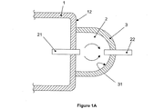
これらの図に示されるように、本明細書に開示される密閉圧縮機は気密筐体および流体膨張チャンバを備え、本発明の大きな発明的価値は、前記流体膨張チャンバは−現在の先端技術で見られるように取り外し可能でそれ自体に適合するよりむしろ−気密筐体の面のうちの1つと気密筐体の面のうちの1つに気密に取り付けられた第一モジュール体の内面との間に形成されるという事実に存する。 As shown in these figures, the hermetic compressor disclosed herein comprises an airtight housing and a fluid expansion chamber, and the great inventive value of the present invention is that the fluid expansion chamber is—in current state of the art. Rather than being removable and conforming to itself as seen-between one of the faces of the hermetic housing and the inner surface of the first module body that is hermetically attached to one of the faces of the hermetic housing Lies in the fact that it is formed.
詳細には、図1Aに示されるように、前記流体膨張チャンバ(2)は気密筐体(1)の外部にあり、気密筐体(1)の外面(12)と第一モジュール体(3)の内面(31)との間に形成されており、これはひいては気密筐体(1)の同じ外面(12)に気密に取り付けられている。図示されるように、前記流体膨張チャンバ(2)は吐出流体膨張チャンバであることに、さらに留意される。 Specifically, as shown in FIG. 1A, the fluid expansion chamber (2) is outside the airtight housing (1), and the outer surface (12) of the airtight housing (1) and the first module body (3). Between the inner surface (31) and the inner surface (31) of the airtight casing (1). It is further noted that, as shown, the fluid expansion chamber (2) is a discharge fluid expansion chamber.
詳細には、図1Bに示されるように、前記流体膨張チャンバ(2)は気密筐体(1)の内部にあり、気密筐体(1)の内面(11)と第一モジュール体(3)の内面(31)との間に形成されており、これはひいては気密筐体(1)の同じ内面(11)に気密に取り付けられている。図示されるように、前記流体膨張チャンバ(2)は吸引流体膨張チャンバであることに、さらに留意される。 Specifically, as shown in FIG. 1B, the fluid expansion chamber (2) is inside the airtight housing (1), and the inner surface (11) of the airtight housing (1) and the first module body (3). Between the inner surface (31) and the inner surface (11) of the airtight casing (1). It is further noted that, as shown, the fluid expansion chamber (2) is a suction fluid expansion chamber.
図1Aおよび図1Bに示される両方の実施形態において、流体膨張チャンバ(2)は少なくとも1つの流入路(21)および少なくとも1つの流出路(22)を備えることに、留意される。 It is noted that in both embodiments shown in FIGS. 1A and 1B, the fluid expansion chamber (2) comprises at least one inflow path (21) and at least one outflow path (22).
図1Aに示される実施形態において、流入路(21)は、気密筐体(1)を迂回してその内部環境を流体膨張チャンバ(2)の容積に接続させる、流体連通手段(2つだけ例を挙げるなら、管または単なる貫通孔)に関する。流出路(22)は、密閉圧縮機とたとえば冷却システムなどの外部システム(図示せず)の吐出ラインとの間の接続を可能にできる流体連通手段(1つだけ例を挙げるなら、吐出ダクト管)に関する。 In the embodiment shown in FIG. 1A, the inflow channel (21) bypasses the hermetic housing (1) and connects its internal environment to the volume of the fluid expansion chamber (2) (only two examples). To mention a tube or just a through-hole). The outflow channel (22) is a fluid communication means that can allow connection between a hermetic compressor and a discharge line of an external system (not shown) such as a cooling system, for example, a discharge duct tube, to name just one example. )
図1Bに示される実施形態において、流入路(21)は、気密筐体(1)を迂回してたとえば冷却システムなどの外部システム(図示せず)と密閉圧縮機との間の接続を可能にできる流体連通手段(1つだけ例を挙げるなら、吸引ダクト管)に関する。流出路(22)は、流体膨張チャンバ(2)の容積を圧縮機の内部環境に、または圧縮機構のシリンダ(図示せず)に接続可能な流体連通手段(2つだけ例を挙げるなら、管または単なる貫通孔)に関する。 In the embodiment shown in FIG. 1B, the inflow channel (21) bypasses the hermetic housing (1) to allow a connection between an external system (not shown), eg a cooling system, and a hermetic compressor. It relates to possible fluid communication means (suction duct tube if only one example is given). The outflow channel (22) is a fluid communication means (tube, if only two examples are given) that can connect the volume of the fluid expansion chamber (2) to the internal environment of the compressor or to the cylinder (not shown) of the compression mechanism. Or just a through-hole).
本発明に説明される残りの実施形態に加えて、図1Aおよび図1Bに示される両方の実施形態において、第一モジュール体(3)は好ましくは金属合金で作られており、好ましくは溶接によって、気密筐体(1)の面(11および12)のうちの1つに取り付けられている。たとえば接着剤など、固定が代替形態のものとなる、ポリマーなどその他のタイプの材料でモジュール体が製造されることを妨げるものは、何もない。 In addition to the remaining embodiments described in the present invention, in both embodiments shown in FIGS. 1A and 1B, the first module body (3) is preferably made of a metal alloy, preferably by welding. , Attached to one of the surfaces (11 and 12) of the hermetic housing (1). There is nothing that prevents the module body from being made of other types of materials, such as polymers, for example, adhesives that are alternative forms of fixation.
本発明は熱的および音響的問題を意図的に解決するものではないが、締結媒体の一般的な特徴と同様に、第一モジュール体(3)の一般的な寸法および構造形式が、各プロジェクトの特徴を尊重すべきであることは、強調するに値する。この点に関して、図1Aおよび図1Bに示される実施形態のいずれにおいても、流体膨張チャンバ(2)の流入路(21)および流出路(22)は流体的に揃って配置されても流体的にずれて配置されてもよいと注記することは、最も重要である。 Although the present invention does not intentionally solve the thermal and acoustic problems, the general dimensions and structure type of the first module body (3), as well as the general characteristics of the fastening medium, are It is worth emphasizing that the characteristics of In this regard, in any of the embodiments shown in FIGS. 1A and 1B, the inflow channel (21) and the outflow channel (22) of the fluid expansion chamber (2) may be fluidly aligned or fluidly arranged. It is most important to note that they may be offset.
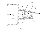
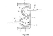
上述の発明の主要部にしたがって、本発明の選択的実施形態は、図2A、図2B、図2C、および図2Dに示されている。 In accordance with the main parts of the invention described above, an alternative embodiment of the invention is shown in FIGS. 2A, 2B, 2C, and 2D.
これらすべての選択的実施形態において、(気密筐体(1)の内部または外部にあり、気密筐体(1)の面(11および12)のうちの1つと気密筐体(1)の面(11および12)のうちの1つに気密に取り付けられた第一モジュール体(3)の内面(31)との間に形成された)前記流体膨張チャンバ(2)の存在、ならびに流体膨張チャンバ(2)に直列で流体接続された少なくとも1つの第二流体膨張チャンバ(4)の存在に、留意される。流体膨張チャンバ(2および4)は、吐出流体の直列容積または吸引流体の直列容積に適合することができる。 In all these alternative embodiments, one of the surfaces (11 and 12) of the hermetic housing (1) and the surface of the hermetic housing (1) (inside or outside of the hermetic housing (1) ( 11) and the presence of said fluid expansion chamber (2) (formed between the inner surface (31) of the first module body (3) which is hermetically attached to one of) and the fluid expansion chamber ( Note the presence of at least one second fluid expansion chamber (4) fluidly connected in series to 2). The fluid expansion chambers (2 and 4) can be adapted to a series volume of discharge fluid or a series volume of suction fluid.
一般的な方式において、第二流体膨張チャンバ(4)の構成は常に第二モジュール体(5)を有し、これもまた一般的な方式において、第一モジュール体(3)と実質的に類似している。 In a general manner, the configuration of the second fluid expansion chamber (4) always has a second module body (5), which is also substantially similar to the first module body (3) in the general manner. doing.
常に第二モジュール体(5)を用いる第二流体膨張チャンバ(4)の構成設定は多様であり、いくつかの例が図2A、図2B、図2C、および図2Dに示されている。 The configuration of the second fluid expansion chamber (4), which always uses the second module body (5), is varied and some examples are shown in FIGS. 2A, 2B, 2C, and 2D.
図2Aに示されるように、流体膨張チャンバ(2)および第二流体膨張チャンバ(4)はいずれも外部にあり、好ましくは吐出流体専用である。この実施形態において、第二流体膨張チャンバ(4)は、第一モジュール体(3)の外面(32)と第二モジュール体(5)の内面(51)との間にのみ形成されている。 As shown in FIG. 2A, both the fluid expansion chamber (2) and the second fluid expansion chamber (4) are external and preferably dedicated to the discharge fluid. In this embodiment, the second fluid expansion chamber (4) is formed only between the outer surface (32) of the first module body (3) and the inner surface (51) of the second module body (5).
図2Bに示されるように、流体膨張チャンバ(2)および第二流体膨張チャンバ(4)はいずれも内部にあり、好ましくは吸引流体専用である。この実施形態において、第二流体膨張チャンバ(4)は、第一モジュール体(3)の外面(32)、気密筐体(1)の内面(11)、および第二モジュール体(5)の内面(51)の間に形成されている。 As shown in FIG. 2B, both the fluid expansion chamber (2) and the second fluid expansion chamber (4) are internal and preferably dedicated to suction fluid. In this embodiment, the second fluid expansion chamber (4) comprises an outer surface (32) of the first module body (3), an inner surface (11) of the airtight housing (1), and an inner surface of the second module body (5). (51).
図2Cに示されるように、流体膨張チャンバ(2)および第二流体膨張チャンバ(4)はいずれも外部にあり、好ましくは吐出流体専用である。この実施形態において、第二流体膨張チャンバ(4)は、第一モジュール体(3)の外面(32)、気密筐体(1)の外面(12)、および第二モジュール体(5)の内面(51)の間に形成されている。 As shown in FIG. 2C, both the fluid expansion chamber (2) and the second fluid expansion chamber (4) are external and preferably dedicated to the discharge fluid. In this embodiment, the second fluid expansion chamber (4) comprises an outer surface (32) of the first module body (3), an outer surface (12) of the airtight housing (1), and an inner surface of the second module body (5). (51).
図2Dに示されるように、流体膨張チャンバ(2)および第二流体膨張チャンバ(4)はいずれも内部にあり、好ましくは吸引流体専用である。この実施形態において、第二流体膨張チャンバ(4)は、気密筐体(1)の内面(11)と第二モジュール体(5)の内面(51)との間にのみ形成されている。 As shown in FIG. 2D, both the fluid expansion chamber (2) and the second fluid expansion chamber (4) are internal and preferably dedicated to aspiration fluid. In this embodiment, the second fluid expansion chamber (4) is formed only between the inner surface (11) of the airtight housing (1) and the inner surface (51) of the second module body (5).
これら4つの実施形態において、流体膨張チャンバ(4)は、流体連通手段(3つの例を挙げるなら、伝統的な管、単なる貫通孔、または貫通管)に向けられた流出路(6)を備えることに、さらに留意される。この意味において、前記流体膨張チャンバ(4)の「流入路」は常に流体膨張チャンバ(2)の流出路(22)によって画定されて終端することに留意される。 In these four embodiments, the fluid expansion chamber (4) comprises an outflow channel (6) directed to a fluid communication means (traditional tube, simple through hole or through tube, to name three examples). Of particular note. In this sense, it is noted that the “inflow path” of the fluid expansion chamber (4) is always defined and terminated by the outflow path (22) of the fluid expansion chamber (2).
流体膨張チャンバ(2)に関して説明(または省略)された構造的詳細(たとえば構造および寸法変動の可能性、および溶接による固定の好適な形態)は、流体膨張チャンバ(4)においても同様に観察される。 The structural details described (or omitted) with respect to the fluid expansion chamber (2) (eg possible structural and dimensional variations and suitable forms of fixation by welding) are also observed in the fluid expansion chamber (4) as well. The
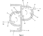
図2A、図2B、図2C、および図2Dに示された選択的実施形態とは対照的に、図3に示される選択的実施形態は、直列で流体接続された2つの流体膨張チャンバの使用を提供するが、これらのチャンバのうちの1つは(圧縮機の筐体に対して)内部に配置され、これらのチャンバのうちのもう1つは(圧縮機の筐体に対して)外部に配置されている。 In contrast to the alternative embodiment shown in FIGS. 2A, 2B, 2C, and 2D, the alternative embodiment shown in FIG. 3 uses two fluid expansion chambers that are fluidly connected in series. One of these chambers is disposed internally (relative to the compressor housing) and the other of these chambers is external (relative to the compressor housing). Is arranged.
このため、図3において任意に規定されるように、気密筐体(1)、第一流体膨張チャンバ(2)、および第二流体膨張チャンバ(4)を備える密閉圧縮機が提供され、このようなチャンバは直列で流体接続されて、吐出流体の直列容積を規定する(これは当然ながら吸引流体の直列容積も規定できる)。 For this purpose, a hermetic compressor comprising an airtight housing (1), a first fluid expansion chamber (2) and a second fluid expansion chamber (4) is provided, as arbitrarily defined in FIG. These chambers are fluidly connected in series to define a series volume of discharge fluid (which can of course also define a series volume of suction fluid).
詳細には、第一流体膨張チャンバ(2)は特に、気密筐体(1)の内面(11)と気密筐体(1)の内面(11)に気密に取り付けられた第一モジュール体(3)の内面(31)との間にのみ形成され、その一方で第二流体膨張チャンバ(4)は特に、気密筐体(1)の外面(12)と気密筐体(1)の外面(12)に気密に取り付けられた第一モジュール体(3)の内面(31)との間にのみ形成されている。容積間の流体接続は、図2A、図2B、図2C、および図2Dに示される構成および選択肢と同じように行われる。 In particular, the first fluid expansion chamber (2) is in particular a first module body (3) which is hermetically attached to the inner surface (11) of the hermetic housing (1) and the inner surface (11) of the hermetic housing (1). ) Between the outer surface (12) of the hermetic housing (1) and the outer surface (12) of the hermetic housing (1). ) Is hermetically attached to the inner surface (31) of the first module body (3). The fluid connection between the volumes is made in the same manner as the configurations and options shown in FIGS. 2A, 2B, 2C, and 2D.
上記の説明は対象の実用新案の特定の実施形態を例示によって説明する目的のみを有すると強調することが重要である。したがって、同じ結果を達成するために実質的に同じやり方で同じ機能を実行する要素の修正例、変形例、および構造的組合せが、添付請求項によって規定された保護範囲に含まれることは、明らかである。 It is important to emphasize that the above description has only the purpose of illustrating a particular embodiment of the subject utility model by way of example. Thus, it is apparent that modifications, variations, and structural combinations of elements that perform the same function in substantially the same way to achieve the same result fall within the scope of protection defined by the appended claims. It is.
1 筐体
2 第一流体膨張チャンバ
3 第一モジュール体
4 第二流体膨張チャンバ
5 第二モジュール体
6、22 流出路
11、31、51 内面
12、32 外面
21 流入路
DESCRIPTION OF
Claims (14)
気密筐体(1)と、
気密筐体(1)内に配置された少なくとも1つの往復圧縮機構(図示せず)と、
少なくとも1つの流体膨張チャンバ(2)と、
を備え、
前記密閉圧縮機は、前記流体膨張チャンバ(2)が気密筐体(1)の面(11、12)のうちの1つと、気密筐体(1)の面(11、12)のうちの1つに気密に取り付けられた第一モジュール体(3)の内面(31)との間に形成され、
前記流体膨張チャンバ(2)は、少なくとも1つの流入路(21)および少なくとも1つの流出路(22)を備えることを特に特徴とする、
密閉圧縮機。 A hermetic compressor,
An airtight housing (1);
At least one reciprocating compression mechanism (not shown) disposed in the hermetic housing (1);
At least one fluid expansion chamber (2);
With
In the hermetic compressor, the fluid expansion chamber (2) is one of the surfaces (11, 12) of the hermetic housing (1) and one of the surfaces (11, 12) of the hermetic housing (1). Formed between the inner surface (31) of the first module body (3) which is airtightly attached to the
The fluid expansion chamber (2) is particularly characterized in that it comprises at least one inflow channel (21) and at least one outflow channel (22),
Hermetic compressor.
Applications Claiming Priority (2)
| Application Number | Priority Date | Filing Date | Title |
|---|---|---|---|
| BR1020160298733 | 2016-12-19 | ||
| BR102016029873A BR102016029873A2 (en) | 2016-12-19 | 2016-12-19 | airtight compressor |
Publications (2)
| Publication Number | Publication Date |
|---|---|
| JP2018100665A true JP2018100665A (en) | 2018-06-28 |
| JP2018100665A5 JP2018100665A5 (en) | 2020-11-19 |
Family
ID=62605734
Family Applications (1)
| Application Number | Title | Priority Date | Filing Date |
|---|---|---|---|
| JP2017235766A Pending JP2018100665A (en) | 2016-12-19 | 2017-12-08 | Hermetic compressor |
Country Status (4)
| Country | Link |
|---|---|
| US (1) | US20180347555A1 (en) |
| JP (1) | JP2018100665A (en) |
| CN (1) | CN108204353B (en) |
| BR (1) | BR102016029873A2 (en) |
Families Citing this family (6)
| Publication number | Priority date | Publication date | Assignee | Title |
|---|---|---|---|---|
| KR102238334B1 (en) * | 2016-05-03 | 2021-04-09 | 엘지전자 주식회사 | Linear compressor |
| JP6473283B1 (en) * | 2017-05-30 | 2019-02-20 | 株式会社アルバック | Vacuum pump |
| EP3470673B1 (en) * | 2017-10-11 | 2021-12-01 | Lg Electronics Inc. | Linear compressor |
| EP3906364A1 (en) * | 2018-12-31 | 2021-11-10 | Bock GmbH | Compressor |
| WO2020223293A1 (en) | 2019-04-29 | 2020-11-05 | Gast Manufacturing, Inc. | Sound reduction device for rocking piston pumps and compressors |
| CN110107481A (en) * | 2019-06-26 | 2019-08-09 | 黄石东贝电器股份有限公司 | A kind of reduction noise mentions high performance shell and compressor |
Citations (5)
| Publication number | Priority date | Publication date | Assignee | Title |
|---|---|---|---|---|
| JPS5480005U (en) * | 1977-11-17 | 1979-06-06 | ||
| JPH07269485A (en) * | 1994-03-31 | 1995-10-17 | Mitsubishi Heavy Ind Ltd | Compressor |
| JP2005325763A (en) * | 2004-05-14 | 2005-11-24 | Nissan Motor Co Ltd | Electric compressor |
| JP2008248717A (en) * | 2007-03-29 | 2008-10-16 | Mitsubishi Electric Corp | Refrigerant compression device |
| JP2009228497A (en) * | 2008-03-21 | 2009-10-08 | Toyota Industries Corp | Compressor |
Family Cites Families (7)
| Publication number | Priority date | Publication date | Assignee | Title |
|---|---|---|---|---|
| JPS61132782A (en) * | 1984-11-29 | 1986-06-20 | Toshiba Corp | Manufacture of compressor valve cover |
| KR100269951B1 (en) * | 1997-11-05 | 2000-10-16 | 배길성 | Sucking muffler of a compressor |
| KR100378803B1 (en) * | 2000-06-12 | 2003-04-07 | 엘지전자 주식회사 | Muffler for compressor |
| BR102012025273B1 (en) * | 2012-10-03 | 2021-09-08 | Embraco Indústria De Compressores E Soluções Em Refrigeração Ltda | COOLING COMPRESSOR |
| BR102012026728A2 (en) * | 2012-10-18 | 2014-08-26 | Whirlpool Sa | EXPANSION CHAMBER FOR ALTERNATIVE COMPRESSOR UNLOADING LINE |
| KR101854933B1 (en) * | 2013-04-24 | 2018-05-04 | 엘지전자 주식회사 | Muffler for compressor and compressor having the same |
| CN205137838U (en) * | 2014-10-20 | 2016-04-06 | 三菱电机株式会社 | Silencer and possess air conditioner of this silencer for air conditioner |
-
2016
- 2016-12-19 BR BR102016029873A patent/BR102016029873A2/en active Search and Examination
-
2017
- 2017-12-08 US US15/835,855 patent/US20180347555A1/en not_active Abandoned
- 2017-12-08 JP JP2017235766A patent/JP2018100665A/en active Pending
- 2017-12-19 CN CN201711370610.0A patent/CN108204353B/en active Active
Patent Citations (5)
| Publication number | Priority date | Publication date | Assignee | Title |
|---|---|---|---|---|
| JPS5480005U (en) * | 1977-11-17 | 1979-06-06 | ||
| JPH07269485A (en) * | 1994-03-31 | 1995-10-17 | Mitsubishi Heavy Ind Ltd | Compressor |
| JP2005325763A (en) * | 2004-05-14 | 2005-11-24 | Nissan Motor Co Ltd | Electric compressor |
| JP2008248717A (en) * | 2007-03-29 | 2008-10-16 | Mitsubishi Electric Corp | Refrigerant compression device |
| JP2009228497A (en) * | 2008-03-21 | 2009-10-08 | Toyota Industries Corp | Compressor |
Also Published As
| Publication number | Publication date |
|---|---|
| CN108204353A (en) | 2018-06-26 |
| US20180347555A1 (en) | 2018-12-06 |
| CN108204353B (en) | 2021-12-17 |
| BR102016029873A2 (en) | 2018-07-17 |
Similar Documents
| Publication | Publication Date | Title |
|---|---|---|
| JP2018100665A (en) | Hermetic compressor | |
| JP5866004B2 (en) | Hermetic compressor and heat pump device | |
| WO2012056728A1 (en) | Screw compressor | |
| US20160305431A1 (en) | Compact low noise rotary compressor | |
| CN107850071B (en) | Screw compressor economizer plenum for pulsation reduction | |
| EP3336355B1 (en) | Hermetic compressor | |
| JP2010048089A (en) | Hermetic compressor | |
| EP3047145B1 (en) | Suction muffler for hermetic compressor | |
| EP1853822B1 (en) | A compressor | |
| BR102016005387A2 (en) | DISCHARGE ACOUSTIC FILTER, PROCESS OF MANUFACTURE OF ACOUSTIC DISCHARGE FILTER AND HERMETIC COMPRESSOR | |
| US9518680B2 (en) | Compressor and valve assembly thereof for reducing pulsation and/or noise | |
| KR100788423B1 (en) | Suction muffler and compressor having the same | |
| WO2013182409A1 (en) | A compressor comprising a cylinder head | |
| US7494328B2 (en) | NVH and gas pulsation reduction in AC compressor | |
| CN112253461B (en) | Compressor, air conditioner and water heater | |
| CN210715117U (en) | Low-position exhaust connecting pipe structure and rotor compressor | |
| US11434887B2 (en) | Linear compressor with suction guide and suction muffler | |
| JP2014001699A (en) | Reciprocating compression apparatus | |
| CN207393474U (en) | Compressor housing and motor compressor | |
| WO2020015899A1 (en) | A compressor with improved operational efficiency | |
| US20220163026A1 (en) | Suction muffler for reciprocating compressor | |
| JP2007515591A (en) | Discharge system for compressor | |
| JP2006529015A (en) | Liquid ring pump | |
| JP5531891B2 (en) | Accumulator for refrigerant compressor | |
| CN116241459A (en) | Exhaust assembly, pump body assembly and scroll compressor |
Legal Events
| Date | Code | Title | Description |
|---|---|---|---|
| A711 | Notification of change in applicant |
Free format text: JAPANESE INTERMEDIATE CODE: A711 Effective date: 20190426 |
|
| RD02 | Notification of acceptance of power of attorney |
Free format text: JAPANESE INTERMEDIATE CODE: A7422 Effective date: 20190612 |
|
| RD04 | Notification of resignation of power of attorney |
Free format text: JAPANESE INTERMEDIATE CODE: A7424 Effective date: 20190614 |
|
| RD03 | Notification of appointment of power of attorney |
Free format text: JAPANESE INTERMEDIATE CODE: A7423 Effective date: 20200131 |
|
| RD04 | Notification of resignation of power of attorney |
Free format text: JAPANESE INTERMEDIATE CODE: A7424 Effective date: 20200309 |
|
| A521 | Request for written amendment filed |
Free format text: JAPANESE INTERMEDIATE CODE: A523 Effective date: 20201006 |
|
| A621 | Written request for application examination |
Free format text: JAPANESE INTERMEDIATE CODE: A621 Effective date: 20201006 |
|
| A977 | Report on retrieval |
Free format text: JAPANESE INTERMEDIATE CODE: A971007 Effective date: 20210812 |
|
| A131 | Notification of reasons for refusal |
Free format text: JAPANESE INTERMEDIATE CODE: A131 Effective date: 20210824 |
|
| A02 | Decision of refusal |
Free format text: JAPANESE INTERMEDIATE CODE: A02 Effective date: 20220315 |