JP2018099713A - Method for bonding metallic component and resin member - Google Patents
Method for bonding metallic component and resin member Download PDFInfo
- Publication number
- JP2018099713A JP2018099713A JP2016247386A JP2016247386A JP2018099713A JP 2018099713 A JP2018099713 A JP 2018099713A JP 2016247386 A JP2016247386 A JP 2016247386A JP 2016247386 A JP2016247386 A JP 2016247386A JP 2018099713 A JP2018099713 A JP 2018099713A
- Authority
- JP
- Japan
- Prior art keywords
- resin member
- metal member
- dowel
- joining
- tip
- Prior art date
- Legal status (The legal status is an assumption and is not a legal conclusion. Google has not performed a legal analysis and makes no representation as to the accuracy of the status listed.)
- Pending
Links
Images


Abstract
Description
本発明は、金属部材と樹脂部材とを重ね合わせて接合する方法に関する。 The present invention relates to a method of superposing and joining a metal member and a resin member.
従来より、重ね合わせた金属部材と樹脂部材を接合する方法としては、リベットやボルト・ナット等を使用して締結する方法(特許文献1)などが知られており、これらの接合方法を用いることで高い接合強度を得ることができる。しかしながら、上述の接合方法では設計自由度の低下、リベットやボルト・ナットといった副資材によるコストアップ・重量アップという問題があった。 Conventionally, as a method of joining the overlapped metal member and the resin member, a method of fastening using a rivet, a bolt, a nut or the like (Patent Document 1) is known, and these joining methods are used. High bonding strength can be obtained. However, the above-described joining method has a problem that the degree of freedom in design is reduced and the cost and weight are increased due to auxiliary materials such as rivets, bolts and nuts.
別の接合方法としては、一方の部材にダボを、他方の部材に貫通孔を形成し、ダボを貫通孔に嵌合してかしめ接合する方法(特許文献2)が知られている。この接合方法によると、リベットやボルト・ナットを必要としないために、使用する部品点数を減らすことが可能となる。 As another joining method, there is known a method (Patent Document 2) in which a dowel is formed in one member, a through hole is formed in the other member, and the dowel is fitted into the through hole and caulked and joined. According to this joining method, since rivets, bolts and nuts are not required, the number of parts to be used can be reduced.
しかしながら、上述の接合方法では所望する接合強度を得るためには,かしめる際に相当な加圧力が必要となるため、装置が大掛かりになり加工に要するエネルギーが大きくなるという問題があった。また、互いの拘束力を確保するため加圧力を大きくすると樹脂部材に亀裂が生じてしまうという問題もあった。 However, in order to obtain a desired bonding strength, the above-described bonding method requires a considerable pressing force when caulking, resulting in a problem that the apparatus becomes large and energy required for processing increases. Moreover, when the applied pressure is increased in order to ensure mutual restraining force, there is a problem that the resin member is cracked.
本発明はこのような問題点を解決するためになされたものであり、追加部品を必要とすることなく、また量産設備(スポット溶接用サーボガンなど)を用いた低い加圧力で接合強度を確保でき、接合時の加圧力に起因する樹脂部材の亀裂を防ぐことができる金属部材と樹脂部材との接合方法を提供することを目的とする。 The present invention has been made to solve such a problem, and it is possible to ensure the bonding strength without using additional parts and with a low pressure using mass production equipment (such as a servo gun for spot welding). An object of the present invention is to provide a method for joining a metal member and a resin member that can prevent cracking of the resin member due to the applied pressure during joining.
請求項1に係る発明は、金属部材と樹脂部材とを接合する方法であって、所定位置にダボを形成した金属部材を準備する工程と、前記ダボに対応する部位に対応する形状の貫通孔を形成した樹脂部材を準備する工程と、前記樹脂部材の前記貫通孔に、前記金属部材の前記ダボが係合されるよう前記樹脂部材と前記金属部材とを重ね合わせる第1の工程と、前記樹脂部材の前記貫通孔と係合した前記金属部材のダボの先端部に第1の電極チップを当接させると同時に前記金属部材のダボの先端部とは反対側の面に形成された凹部に第2の電極チップを当接させ、前記第1、第2の電極チップ間に通電して前記金属部材を発熱、軟化させ、さらに前記樹脂部材に伝熱させることにより前記樹脂部材を軟化または溶融する第2の工程と、前記第1、第2の電極チップ間に加圧力を付加することにより、前記ダボの先端部を潰すと同時に径方向外方へ押し広げ、かつ前記金属部材と前記樹脂部材の係合部分を変形密着させて金属部材と樹脂部材とを接合する第3の工程とを含む。
The invention according to
請求項2に係る発明は請求項1の構成に加えて、前記第1、第2の電極チップ間に付加する加圧力が1.4から4.0kNであることを特徴とする。 According to a second aspect of the present invention, in addition to the configuration of the first aspect, a pressure applied between the first and second electrode chips is 1.4 to 4.0 kN.
請求項3に係る発明は請求項1または請求項2の構成に加えて、前記第1、第2の電極チップ間により、被加工物に通電を行う第2の工程と加圧を行う第3の工程は、スポット溶接用の通常のサーボガンにより行うことを特徴とする。 According to a third aspect of the invention, in addition to the configuration of the first or second aspect, a second step of energizing the workpiece and a third portion of applying pressure between the first and second electrode tips. This step is performed by a normal servo gun for spot welding.
請求項4に係る発明は請求項2または請求項3の構成に加えて、前記金属部材が合金化溶融亜鉛メッキ鋼板であり、かつ前記第1、第2の電極チップ間に通電する電流値が1.7から3.5kAであることを特徴とする。 According to a fourth aspect of the invention, in addition to the configuration of the second or third aspect, the metal member is an alloyed hot-dip galvanized steel sheet, and a current value to be passed between the first and second electrode tips is It is characterized by 1.7 to 3.5 kA.
請求項5に係る発明は請求項2または請求項3の構成に加えて、前記金属部材がアルミニウム合金であり、かつ前記第1、第2の電極チップ間に通電する電流値が4.9から10.0kAであることを特徴とする。 According to a fifth aspect of the present invention, in addition to the configuration of the second or third aspect, the metal member is an aluminum alloy, and a current value applied between the first and second electrode tips is from 4.9. It is characterized by 10.0 kA.
請求項6に係る発明は、請求項1乃至請求項3の構成に加えて、第1の工程と第2の工程の間に、前記ダボに係合した前記樹脂部材の上部に金属製のワッシャーを更に係合させる工程を有することを特徴とする。 According to a sixth aspect of the present invention, in addition to the configurations of the first to third aspects, a metal washer is provided on the upper portion of the resin member engaged with the dowel between the first step and the second step. The method further includes the step of further engaging.
請求項1記載の発明によれば、重ね合わせた樹脂部材と金属部材とを第1、第2の電極で当接して通電することで金属部材を発熱、軟化させ、さらに樹脂部材に伝熱させることにより樹脂部材を軟化または溶融する。そして、第1、第2の電極チップ間に加圧力を付加することにより、ダボの先端部を潰すと同時に径方向外方へ押し広げ、かつ金属部材と樹脂部材の係合部分を変形密着させて接合する。よって、軟化または溶融した樹脂部材の形状が当接する金属部材になじむように変形し、密着した状態で両部材が接合可能となる。また、金属部材を発熱、軟化させ、樹脂部材を軟化または溶融した後に加圧して接合するため、少ない加圧力で強固に接合することができる。 According to the first aspect of the present invention, the metal member is heated and softened by contacting the energized resin member and the metal member with the first and second electrodes and energized, and further the heat is transferred to the resin member. As a result, the resin member is softened or melted. Then, by applying a pressure force between the first and second electrode tips, the tip of the dowel is crushed and simultaneously spread outward in the radial direction, and the engagement portion between the metal member and the resin member is deformed and adhered. And join. Therefore, the shape of the softened or melted resin member is deformed so as to be compatible with the abutting metal member, and the two members can be joined in a closely contacted state. Further, since the metal member is heated and softened and the resin member is softened or melted and then pressed and joined, it can be firmly joined with a small applied pressure.
請求項2記載の発明によれば、前記第1、第2の電極チップ間に付加する加圧力が1.4から4.0kNである。通電を行わずカシメ加工を行わせる場合は10kN程度の加圧力が必要となるが、通電と組み合わせる本発明の構成により遥かに低い加圧力での加工が可能となり、スポット溶接用サーボガンなどの量産設備を流用することが可能となる。
なお加圧力が1.4kN以下の場合は、加圧力が小さすぎるため十分にダボを変形させることが出来ず接合強度が不十分となり、加圧力が4.0kN以上の場合は、加圧力が大きすぎるためダボが過度に変形し、かえって接合力の低下を招き樹脂部材の変形・亀裂が生じる恐れがある。請求項2記載の条件下で本発明方法を実施することにより、高い接合強度を確実に得ることができる。
According to a second aspect of the present invention, the pressure applied between the first and second electrode chips is 1.4 to 4.0 kN. When caulking is performed without energization, a pressing force of about 10 kN is required. However, the construction of the present invention combined with energization enables processing with a much lower pressing force and mass production equipment such as a servo gun for spot welding. Can be diverted.
When the applied pressure is 1.4 kN or less, the applied pressure is too small to sufficiently deform the dowel, resulting in insufficient bonding strength. When the applied pressure is 4.0 kN or more, the applied pressure is large. For this reason, the dowels are deformed excessively, and on the contrary, the bonding force may be reduced, and the resin member may be deformed or cracked. By carrying out the method of the present invention under the conditions described in
請求項3記載の発明によれば、前記第1、第2の電極チップ間により、被加工物に通電を行う第2の工程と加圧を行う第3の工程は、スポット溶接用の通常のサーボガンにより行うことができ、スポット溶接用サーボガンなどの量産設備を流用することが可能となる。 According to the third aspect of the present invention, the second step of energizing the workpiece and the third step of pressurization between the first and second electrode tips are usually performed for spot welding. Servo guns can be used, and mass production equipment such as spot welding servo guns can be used.
請求項4記載の発明によれば、金属部材が合金化溶融亜鉛メッキ鋼板であり、かつ第1、第2の電極チップ間に通電する電流値が1.7から3.5kAであることが好適である。このような条件下で本発明方法を実施することにより、高い接合強度を確実に得ることができる。 According to the fourth aspect of the present invention, it is preferable that the metal member is an alloyed hot-dip galvanized steel sheet and the current value applied between the first and second electrode tips is 1.7 to 3.5 kA. It is. By carrying out the method of the present invention under such conditions, a high bonding strength can be reliably obtained.
請求項5記載の発明によれば、金属部材がアルミニウム合金であり、かつ第1、第2の電極チップ間に通電する電流値が4.9から10.0kAであることが好適である。このような条件下で本発明方法を実施することにより、高い接合強度を確実に得ることができる。 According to the fifth aspect of the present invention, it is preferable that the metal member is an aluminum alloy, and a current value to be passed between the first and second electrode tips is 4.9 to 10.0 kA. By carrying out the method of the present invention under such conditions, a high bonding strength can be reliably obtained.
請求項6記載の発明によれば、ワッシャー追加による重量アップを最小限に抑えた上で、より高い接合強度を確実に得ることができる。 According to the sixth aspect of the present invention, it is possible to reliably obtain a higher bonding strength while minimizing the weight increase due to the addition of the washer.
以下、本発明の実施形態について図面に基づいて説明する。尚、以下の実施形態の説明は、本質的な例示に過ぎず、本発明、その適用物或いはその用途を制限することを意図するものではない。 Hereinafter, embodiments of the present invention will be described with reference to the drawings. Note that the following description of the embodiment is merely an exemplification, and is not intended to limit the present invention, its application, or its use.
まず接合しようとする金属部材1と樹脂部材2を用意する。金属部材1は板状部材であり、図1(a)に示すようにダボ1aを有している。タボ1aは金属部材1の厚さの約10倍の高さで形成され、ダボ1aの先端部とは反対側の面には凹部1bが形成されている。ダボは例えばプレス成型により周知の手法で形成できるが、ダボの大きさ、高さ、板厚、材質などにより最適な金型設計、工程設計を行う必要があり、深絞りの場合は通常2以上の工程で製作する。
First, a
樹脂部材2についても板状部材であり、図1(a)に示すように貫通孔2aを有している。貫通穴はパンチ加工、ドリル加工などの周知の方法で加工できる。そして、図1(a)に示すように、樹脂部材2の貫通孔2aに金属部材1のダボ1aを係合し、ダボ1aが貫通孔を通過して樹脂部材2の上に突出するように樹脂部材2と金属部材1を重ね合わせる。
The
本発明では、金属部材1として直径6mm、高さ10mmのダボ1aを形成した厚さ1mmの合金化溶融亜鉛メッキ鋼板(図中ではGAと略記)およびアルミニウム合金(図中ではALと略記)を用意した。また、樹脂部材2として直径6.3mmの貫通孔2aを形成した厚さ2mmのポリアミド(図中ではPAと略記)および炭素繊維強化プラスチック(図中ではCFRPと略記)を用意した。
In the present invention, a 1 mm-thick galvannealed steel sheet (abbreviated as GA in the figure) and an aluminum alloy (abbreviated as AL in the figure) having a
これらの金属部材1と樹脂部材2を接合する本発明の実験においては、図示していないが量産で用いられる通常のサーボガン(インバーター直流トランス式、最大電流15kA、最大加圧力3.0kN)を用いた。また電極としては図1に示す第1、第2の電極チップ3、4を用いた。第1の電極チップ3は直径13mmの円柱状で先端はフラットに形成されている。また、第2の電極チップ4は同様に直径13mmで先端部4aは、ダボの凹部1bと係合するよう直径約6mmの範囲で曲率半径Rが40mmの部分球面形状となるように形成されている。第2の電極チップの先端部4aの中心部分を部分球面形状としているのは、金属部材1に当接する際にダボの凹部1bに当接して金属部材1の動きを規制するためである。
In the experiment of the present invention for joining the
樹脂部材2の貫通孔2a内に位置する金属部材1のダボ1a先端部に、第1の電極チップ3を当接させ、金属部材1のダボ1a先端部とは反対側の面に形成された凹部1bに第2の電極チップを当接させる。次いでサーボガンを作動させて第1、第2の電極チップ3,4間に所定の電流パルスを印加すると、第1、第2の電極チップ3、4間に位置する金属部材1に抵抗発熱が生じて金属部材1は軟化し、ダボ1aの接触面に沿って樹脂部材2に伝熱する。これにより、ダボ1a周辺の樹脂部材2が軟化または溶融する。
The
次にサーボガンを作動させて第1、第2の電極チップ3、4間に所定の加圧力を付加することにより、ダボ1aの先端部が第1の電極チップ3により軸方向(図1(a)下方)に押圧されかしめ加工が開始する。前述の金属部材1が軟化している効果により、サーボガンの通常の加圧力にもかかわらず、図1(b)に示すように、ダボ1aの先端部が潰されると同時に、ダボ1aの貫通孔2aから突出している部分には、貫通孔2aの開口周縁部で径方向外方へ拡がるように変形する負荷が生じ、ダボ1aの先端部が樹脂部材2の表面に密着して沿うように拡径状に変形する。また前述のように樹脂部材2が軟化・溶融している効果で、樹脂が周囲の金属部材1と密着・接合し、金属部材1と樹脂部材2とを、少ない加圧力で強固に接合することができる。
Next, a predetermined pressure is applied between the first and
第1の実施形態では、金属部材1として、合金化溶融亜鉛メッキ鋼板を、樹脂部材2として、ポリアミドおよび炭素繊維強化プラスチックを用いて、通電サイクル数(20サイクル・60Hz)と電極チップ間に印加する加圧力(2.5KN)を一定にし、電極チップ間に通電する電流を2.0KAから3.0KAに変化させた場合における接合部の形状の観察と接合部の強度を計測する実験を行った。
In the first embodiment, an alloyed hot-dip galvanized steel sheet is used as the
図2は、接合部の断面形状を図示している。本実験では図2に示す傘サイズと高さを計測して評価した。図3は、金属部材1として合金化溶融亜鉛メッキ鋼板を、樹脂部材2としてポリアミドを用いた場合の各電流値における接合後の金属部材1の傘サイズと高さの関係を示したグラフである。図3によると、電流が高いほどかしめ高さは低くなり、傘サイズは拡がることが示されている。
FIG. 2 illustrates the cross-sectional shape of the joint. In this experiment, the umbrella size and height shown in FIG. 2 were measured and evaluated. FIG. 3 is a graph showing the relationship between the umbrella size and height of the
図4は各接合条件における引張りせん断強度の結果を示した表であり、各電流値において引張りせん断強度の計測を3回ずつ行った。図4によると、どちらの樹脂部材2においても、電流値が高いほど引張せん断強度が高くなっていることが示されている。
FIG. 4 is a table showing the results of the tensile shear strength under each joining condition, and the tensile shear strength was measured three times at each current value. FIG. 4 shows that the tensile shear strength increases as the current value increases in both
また、図5は各接合条件における十字剥離強度の結果を示した表であり、各電流値において剥離強度の計測を3回ずつ行った。図5によると、樹脂部材2にポリアミドを使用した場合、剥離強度は電流値が2.0KAの時と比較すると3.0KAで低下している。これは、接合時の温度がポリアミドの分解点を越える高温になって結晶性が低下するため、樹脂部材2の構造強度が低下するものと考えられ、特に剥離方向への力に影響を与えるものと考えられる。但し引張りせん断強度は電流値が3.0KAにおいて低下は見られず、継手の構造を工夫してせん断方向で荷重を受けるようにすれば3.0KAでかしめ加工を行った継手も実用上問題ないと考えられる。
FIG. 5 is a table showing the results of the cross peel strength under each bonding condition. The peel strength was measured three times at each current value. According to FIG. 5, when polyamide is used for the
従来のかしめ接合方法では、本実施形態で使用した金属部材1と樹脂部材2とを接合して好ましい接合部の形状と接合強度を得るためには、加圧力が9.8KN必要であった。本発明の第1の実施形態によれば、溶接条件に設定したどの電流値においても、前記の通常のサーボガンを用いた2.5KN(従来の約1/4)という低い加圧力で、適切な接合部の形状と接合強度を得ることができる。本実施例では、電極チップ間に付加する加圧力を2.5KNという一定条件のもと実験を行ったが、加圧力を2.0KNから3.0KNの間で変化させても好適な接合強度を得ることができる。
In the conventional caulking and joining method, a pressure of 9.8 KN is required to obtain a preferable shape and joining strength of the joining portion by joining the
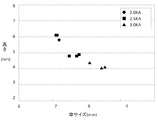
第2の実施形態では、サーボガンおよび電極は第1の実施例と同一の構成を用い、金属部材1としてアルミニウム合金を、樹脂部材2としてポリアミドおよび炭素繊維強化プラスチックを用いて、通電サイクル数(20サイクル・60Hz)と電極チップ間に印加する加圧力(2.5KN)を一定にし、電極チップ間に通電する電流を6.5KAから7.5KAに変化させた場合における接合部の形状の観察と接合部の強度を計測する実験を行った。
In the second embodiment, the servo gun and the electrode have the same configuration as in the first embodiment, an aluminum alloy is used as the
図6は、金属部材1としてアルミニウム合金を、樹脂部材2としてポリアミドを用いた場合の各電流値における接合後の金属部材1の傘サイズと高さの関係を示したグラフである。図6によると、電流が高いほどかしめ高さは低くなったが、傘サイズはあまり変化が見られないことが分かる。
FIG. 6 is a graph showing the relationship between the umbrella size and height of the
また図12はポリアミドとアルミニウム合金でかしめ加工を行った場合の断面をSEMにより観察した画像である。かしめ加工を行ったダボ周辺部分のかなりの部位で樹脂と金属が密着・接合していることがわかる。またSCANCO社製μCT35を用いた解析により、当該部位のポリアミドとアルミの接触率が41%であることが判った。これによりダボかしめ加工による機械的な接合に加えて、ダボ周囲で樹脂と金属が密着・接合することによる接合効果によってより強固な接合が実現していることが確認できる。 Further, FIG. 12 is an image obtained by observing a cross section by SEM when caulking is performed with polyamide and an aluminum alloy. It can be seen that the resin and the metal are in close contact and bonded at a considerable portion around the dowel that has been caulked. In addition, analysis using SCANCO's μCT35 revealed that the contact ratio between the polyamide and the aluminum at the site was 41%. As a result, in addition to mechanical joining by dowel caulking, it can be confirmed that stronger joining is realized by the joining effect caused by the resin and metal closely contacting and joining around the dowel.
図7は各接合条件における引張りせん断強度の結果を示した表であり、各電流値において引張せん断強度の計測を3回ずつ行った。図7によると、どちらの樹脂部材2においても、電流値が高いほど引張せん断強度も高くなっていることが示されている。
FIG. 7 is a table showing the results of the tensile shear strength under each joining condition, and the tensile shear strength was measured three times at each current value. According to FIG. 7, in any of the
図8は各接合条件における十字剥離強度の結果を示した表であり、各電流値において剥離強度の計測を3回ずつ行った。図8によると、樹脂部材2にポリアミドを使用した場合、剥離強度は電流値が6.5KAの時と比較すると7.5KAでは低下している。これは、金属部材1に合金化溶融亜鉛メッキ鋼板を用いた場合と同様、接合時の温度がポリアミドの分解点を越える高温になって結晶性が低下するため、ポリアミドの構造強度が低下するものと考えられ、特に剥離方向への力に影響を与えるものと考えられる。また同様に引張りせん断強度は電流値が7.5KAにおいても低下はないため、この電流値での接合も実用上問題ないと考えられる。
FIG. 8 is a table showing the results of the cross peel strength under each joining condition. The peel strength was measured three times at each current value. According to FIG. 8, when polyamide is used for the
第2の実施形態によれば、溶接条件に設定したどの電流値においても通常のサーボガンを用いた2.5KN(従来の約1/4)という低い加圧力で、適切な接合部の形状と接合強度を得ることができる。本実施例では、電極チップ間に付加する加圧力を2.5KNという一定条件のもと実験を行ったが、加圧力を2.0KNから3.0KNの間で変化させても好適な接合強度を得ることができる。 According to the second embodiment, at any current value set as a welding condition, an appropriate joint shape and joint can be obtained with a low pressurization force of 2.5 KN (about 1/4 of the conventional one) using a normal servo gun. Strength can be obtained. In this example, the experiment was performed under the condition that the applied pressure applied between the electrode tips was 2.5 KN. However, suitable bonding strength can be obtained even if the applied pressure is changed between 2.0 KN and 3.0 KN. Can be obtained.
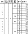
第3の実施形態においては、サーボガンおよび電極は第1、第2の実施例と同一の構成を用い、金属部材1として、合金化溶融亜鉛メッキ鋼板を、樹脂部材2として、ポリアミドおよび炭素繊維強化プラスチックを用いて、通電サイクル数(20サイクル・60Hz)、電極チップ間に印加する加圧力(2.5KN)、及び電極チップ間に通電する電流値(2.5KA)を一定とし、図9に示すように金属製のワッシャー5を樹脂部材2の上に配置した場合の接合部の接合強度を計測する実験を行った。
In the third embodiment, the servo gun and the electrode have the same configuration as those of the first and second embodiments, the alloyed hot-dip galvanized steel sheet is used as the
図10は各接合条件における引張せん断強度を、図11は各接合条件における十時剥離強度の結果を示している。各樹脂部材において引張せん断強度の計測を3回ずつ、剥離強度については計測を1回ずつ行った。図10、図11によれば、引張せん断強度及び十字剥離強度ともにワッシャー5を用いない場合と比較すると強度が上昇する結果となった。これは、ワッシャー5を用いることにより、広い面積で接合する部材を押えることができたためと考えられる。本実験で使用したワッシャー5の重量はわずか0.69gであり、ほとんど重量増大を招くことなく、高強度な接合が可能となる。
FIG. 10 shows the tensile shear strength under each joining condition, and FIG. 11 shows the result of the ten-time peel strength under each joining condition. The tensile shear strength was measured three times for each resin member, and the peel strength was measured once. According to FIGS. 10 and 11, both the tensile shear strength and the cross peel strength are higher than when the
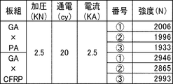
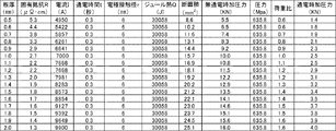
図13は、金属部材1として板厚1.0mmの合金化溶融亜鉛メッキ鋼板を用い、電極チップ間に通電する電流を2.5KA、電極チップ間に印加する加圧力を2.5KN、通電サイクル数を20サイクル・60Hzとして第1の実施形態で行った実験結果に基づき、合金化溶融亜鉛メッキ鋼板の板厚を変化させた場合における接合時の電流値および加圧力を算出した表である。
FIG. 13 shows an alloyed hot-dip galvanized steel sheet having a plate thickness of 1.0 mm as the
算出方法としては、まずジュールの法則より固有抵抗をR、電流値をI、通電時間をt、電極接触径をrとすると、発生するジュール熱QはQ=RI2t/r4であり、板厚1.0mmの合金化亜鉛メッキ鋼板を用いた場合のジュール熱Qは14034Jとなる。また板厚1.0mmの合金化亜鉛メッキ鋼板を用いた場合の圧力(Pa)は、無通電時加圧力とダボの断面積により算出され、圧力は624.2MPaとなる。圧力(624.2MPa)と各板厚のダボ断面積により各板厚の無通電時加圧力を算出し、板厚1.0mmの合金化亜鉛メッキ鋼板を用いた場合の無通電時加圧力(9.8KN)から板厚1.0mmに対する荷重比を求めた。無通電時と通電時の接合時の荷重比は同じであるという前提条件のもと、ジュール熱14034J時の各板厚の合金化溶融亜鉛メッキ鋼板を接合するのに必要な加圧力を算出した。 As a calculation method, first, assuming Joule's law, the specific resistance is R, the current value is I, the energization time is t, and the electrode contact diameter is r, the generated Joule heat Q is Q = RI 2 t / r 4 , The Joule heat Q when using a galvanized steel sheet having a thickness of 1.0 mm is 14034J. Moreover, the pressure (Pa) at the time of using an alloyed galvanized steel plate with a plate thickness of 1.0 mm is calculated from the pressure when not energized and the cross-sectional area of the dowel, and the pressure is 624.2 MPa. The non-energized applied pressure for each plate thickness is calculated from the pressure (624.2 MPa) and the dowel cross-sectional area of each plate thickness. The load ratio with respect to the plate thickness of 1.0 mm was determined from 9.8 KN). Under the precondition that the load ratio at the time of non-energization and bonding at the time of energization is the same, the pressurizing force necessary to join the alloyed hot-dip galvanized steel sheets of each plate thickness at Joule heat 14034J was calculated. .
図13に示すように、合金化溶融亜鉛メッキ鋼板の板厚を0.5から2.0mmの間で、また第1、第2の電極チップ間に通電する電流値を1.7から3.5kAの間で変化させても、通常のサーボガンを用いた1.4から4.0KNという低い加圧力で、適切な接合部の形状と接合強度を得ることができる。 As shown in FIG. 13, the thickness of the alloyed hot-dip galvanized steel sheet is between 0.5 and 2.0 mm, and the current value applied between the first and second electrode tips is between 1.7 and 3. Even if it is changed between 5 kA, it is possible to obtain an appropriate joint shape and joint strength with a low pressure of 1.4 to 4.0 KN using a normal servo gun.
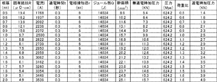
図14は、金属部材1として板厚1.0mmのアルミニウム合金を用い、電極チップ間に通電する電流を7.0KA、電極チップ間に印加する加圧力を2.5KN、通電サイクル数を20サイクル・60Hzとして第2の実施形態で行った実験結果に基づき、アルミニウム合金の板厚を変化させた場合における接合時の電流値および加圧力を算出した表である。
In FIG. 14, an aluminum alloy having a plate thickness of 1.0 mm is used as the
上述と同様の算出方法で、通電時の各板厚のアルミニウム合金を接合するのに必要な加圧力を算出した。 With the same calculation method as described above, the pressurizing force required to join the aluminum alloys having different thicknesses during energization was calculated.
図14に示すように、アルミニウム合金の板厚を0.5から2.0mmの間で、また第1、第2の電極チップ間に通電する電流値を4.9から10.0kAの間で変化させても、通常のサーボガンを用いた1.4から4.0KNという低い加圧力で、適切な接合部の形状と接合強度を得ることができる。 As shown in FIG. 14, the thickness of the aluminum alloy is between 0.5 and 2.0 mm, and the current value applied between the first and second electrode tips is between 4.9 and 10.0 kA. Even if it is changed, it is possible to obtain an appropriate joint shape and joint strength with a low pressure of 1.4 to 4.0 KN using a normal servo gun.
上記の実施形態では、金属部材1として、合金化溶融亜鉛メッキ鋼板とアルミニウム合金を使用する場合を例示したが、これに限定されず、本発明は、アルミニウムや亜鉛めっき処理を施していない鋼板等にも適用可能である。
In said embodiment, although the case where an alloyed hot-dip galvanized steel plate and an aluminum alloy were used was illustrated as the
1 金属部材
1a ダボ
2 樹脂部材
2a 貫通孔
3 第1の電極チップ
4 第2の電極チップ
DESCRIPTION OF
Claims (6)
所定位置にダボを形成した金属部材を準備する工程と、
前記ダボに対応する部位に対応する形状の貫通孔を形成した樹脂部材を準備する工程と、
前記樹脂部材の前記貫通孔に、前記金属部材の前記ダボが係合されるよう前記樹脂部材と前記金属部材とを重ね合わせる第1の工程と、
前記樹脂部材の前記貫通孔と係合した前記金属部材のダボの先端部に第1の電極チップを当接させると同時に前記金属部材のダボの先端部とは反対側の面に形成された凹部に第2の電極チップを当接させ、前記第1、第2の電極チップ間に通電して前記金属部材を発熱、軟化させ、さらに前記樹脂部材に伝熱させることにより前記樹脂部材を軟化または溶融する第2の工程と、
前記第1、第2の電極チップ間に加圧力を付加することにより、前記ダボの先端部を潰すと同時に径方向外方へ押し広げ、かつ前記金属部材と前記樹脂部材の係合部分を変形密着させて金属部材と樹脂部材とを接合する第3の工程と
を含む、金属部材と樹脂部材との接合方法。 A method of joining a metal member and a resin member,
Preparing a metal member having a dowel formed in a predetermined position;
Preparing a resin member having a through-hole having a shape corresponding to a portion corresponding to the dowel;
A first step of overlapping the resin member and the metal member so that the dowels of the metal member are engaged with the through holes of the resin member;
A recess formed on the surface of the metal member opposite to the tip of the dowel at the same time as the first electrode tip is brought into contact with the tip of the dowel of the metal member engaged with the through hole of the resin member The second electrode tip is brought into contact with the first and second electrode tips to generate heat and soften the metal member, and further heat transfer to the resin member softens the resin member. A second step of melting;
By applying a pressure force between the first and second electrode tips, the tip of the dowel is crushed and simultaneously spread outward in the radial direction, and the engagement portion between the metal member and the resin member is deformed. A method for joining a metal member and a resin member, comprising: a third step of bonding the metal member and the resin member together.
請求項1または請求項2に記載の金属部材と樹脂部材との接合方法。 The second step of energizing the workpiece and the third step of applying pressure between the first and second electrode tips are performed by a normal servo gun for spot welding.
The joining method of the metal member of Claim 1 or Claim 2, and a resin member.
請求項2または請求項3に記載の金属部材と樹脂部材との接合方法。 The metal member is an alloyed hot-dip galvanized steel sheet, and a current value applied between the first and second electrode tips is 1.7 to 3.5 kA. 3. A method for joining the metal member and the resin member according to 3.
請求項2または請求項3に記載の金属部材と樹脂部材との接合方法。 The metal member is an aluminum alloy, and a current value applied between the first and second electrode tips is 4.9 to 10.0 kA,
The joining method of the metal member and resin member of Claim 2 or Claim 3.
請求項1乃至請求項3に記載の金属部材と樹脂部材との接合方法。
Between the first step and the second step, the method further comprises a step of further engaging a metal washer on an upper portion of the resin member engaged with the dowel.
The joining method of the metal member and resin member of Claim 1 thru | or 3.
Priority Applications (1)
| Application Number | Priority Date | Filing Date | Title |
|---|---|---|---|
| JP2016247386A JP2018099713A (en) | 2016-12-21 | 2016-12-21 | Method for bonding metallic component and resin member |
Applications Claiming Priority (1)
| Application Number | Priority Date | Filing Date | Title |
|---|---|---|---|
| JP2016247386A JP2018099713A (en) | 2016-12-21 | 2016-12-21 | Method for bonding metallic component and resin member |
Publications (1)
| Publication Number | Publication Date |
|---|---|
| JP2018099713A true JP2018099713A (en) | 2018-06-28 |
Family
ID=62714864
Family Applications (1)
| Application Number | Title | Priority Date | Filing Date |
|---|---|---|---|
| JP2016247386A Pending JP2018099713A (en) | 2016-12-21 | 2016-12-21 | Method for bonding metallic component and resin member |
Country Status (1)
| Country | Link |
|---|---|
| JP (1) | JP2018099713A (en) |
Cited By (1)
| Publication number | Priority date | Publication date | Assignee | Title |
|---|---|---|---|---|
| CN109968680A (en) * | 2019-04-12 | 2019-07-05 | 吉林大学 | A kind of carbon fibre composite and aluminium alloy based on pulse current is without rivet riveting device and method |
-
2016
- 2016-12-21 JP JP2016247386A patent/JP2018099713A/en active Pending
Cited By (2)
| Publication number | Priority date | Publication date | Assignee | Title |
|---|---|---|---|---|
| CN109968680A (en) * | 2019-04-12 | 2019-07-05 | 吉林大学 | A kind of carbon fibre composite and aluminium alloy based on pulse current is without rivet riveting device and method |
| CN109968680B (en) * | 2019-04-12 | 2023-09-08 | 吉林大学 | Pulse current-based carbon fiber composite material and aluminum alloy rivet-free riveting device and method |
Similar Documents
| Publication | Publication Date | Title |
|---|---|---|
| US11196185B2 (en) | Resistance welding fastener, apparatus and methods | |
| JP5468350B2 (en) | Dissimilar metal plate joining method | |
| JP6646679B2 (en) | Resistance welding fastener, apparatus and method for joining similar and dissimilar materials | |
| US20190224774A1 (en) | Resistance Welding Fastener, Apparatus and Methods | |
| US7267736B2 (en) | Method of joining dissimilar materials | |
| WO2016103376A1 (en) | Different material joining structure and different material joining method | |
| WO2016103375A1 (en) | Different material joining structure and different material joining method | |
| US20180361498A1 (en) | Welding methods including formation of an intermediate joint using a solid state welding process | |
| US10384297B2 (en) | Method and device for joining a composite sheet metal component to a functional element | |
| JP2018099713A (en) | Method for bonding metallic component and resin member | |
| JP4580762B2 (en) | Method for joining two or more components together | |
| JP7131634B2 (en) | Steel member manufacturing method | |
| JP7364902B2 (en) | Manufacturing method of riveted joint structure, riveted joint structure and automobile parts | |
| JP2017506583A (en) | Dissimilar materials joining method | |
| JP2022039534A (en) | Dissimilar material joining method, and rivet with use thereof | |
| Lin et al. | Development of friction stir clinching process for alclad 2024-T3 aluminum sheets | |
| JP2017070995A (en) | Method for joining heterogeneous metal plate and component for joining heterogeneous metal plate | |
| WO2022050089A1 (en) | Method for joining dissimilar materials, and rivet used in same | |
| JP7389353B2 (en) | Manufacturing method of riveted joint structure, riveted joint structure, and automobile parts |