JP2018097148A - Image projection system, image projection device, and image projection method - Google Patents
Image projection system, image projection device, and image projection method Download PDFInfo
- Publication number
- JP2018097148A JP2018097148A JP2016241378A JP2016241378A JP2018097148A JP 2018097148 A JP2018097148 A JP 2018097148A JP 2016241378 A JP2016241378 A JP 2016241378A JP 2016241378 A JP2016241378 A JP 2016241378A JP 2018097148 A JP2018097148 A JP 2018097148A
- Authority
- JP
- Japan
- Prior art keywords
- image
- person
- imaging device
- projection
- information
- Prior art date
- Legal status (The legal status is an assumption and is not a legal conclusion. Google has not performed a legal analysis and makes no representation as to the accuracy of the status listed.)
- Pending
Links
Images


Classifications
-
- H—ELECTRICITY
- H04—ELECTRIC COMMUNICATION TECHNIQUE
- H04N—PICTORIAL COMMUNICATION, e.g. TELEVISION
- H04N9/00—Details of colour television systems
- H04N9/12—Picture reproducers
- H04N9/31—Projection devices for colour picture display, e.g. using electronic spatial light modulators [ESLM]
- H04N9/3179—Video signal processing therefor
- H04N9/3185—Geometric adjustment, e.g. keystone or convergence
-
- G—PHYSICS
- G03—PHOTOGRAPHY; CINEMATOGRAPHY; ANALOGOUS TECHNIQUES USING WAVES OTHER THAN OPTICAL WAVES; ELECTROGRAPHY; HOLOGRAPHY
- G03B—APPARATUS OR ARRANGEMENTS FOR TAKING PHOTOGRAPHS OR FOR PROJECTING OR VIEWING THEM; APPARATUS OR ARRANGEMENTS EMPLOYING ANALOGOUS TECHNIQUES USING WAVES OTHER THAN OPTICAL WAVES; ACCESSORIES THEREFOR
- G03B21/00—Projectors or projection-type viewers; Accessories therefor
- G03B21/14—Details
-
- G—PHYSICS
- G06—COMPUTING; CALCULATING OR COUNTING
- G06V—IMAGE OR VIDEO RECOGNITION OR UNDERSTANDING
- G06V10/00—Arrangements for image or video recognition or understanding
- G06V10/10—Image acquisition
- G06V10/12—Details of acquisition arrangements; Constructional details thereof
- G06V10/14—Optical characteristics of the device performing the acquisition or on the illumination arrangements
- G06V10/145—Illumination specially adapted for pattern recognition, e.g. using gratings
-
- G—PHYSICS
- G06—COMPUTING; CALCULATING OR COUNTING
- G06V—IMAGE OR VIDEO RECOGNITION OR UNDERSTANDING
- G06V40/00—Recognition of biometric, human-related or animal-related patterns in image or video data
- G06V40/10—Human or animal bodies, e.g. vehicle occupants or pedestrians; Body parts, e.g. hands
- G06V40/16—Human faces, e.g. facial parts, sketches or expressions
- G06V40/161—Detection; Localisation; Normalisation
- G06V40/166—Detection; Localisation; Normalisation using acquisition arrangements
-
- G—PHYSICS
- G09—EDUCATION; CRYPTOGRAPHY; DISPLAY; ADVERTISING; SEALS
- G09G—ARRANGEMENTS OR CIRCUITS FOR CONTROL OF INDICATING DEVICES USING STATIC MEANS TO PRESENT VARIABLE INFORMATION
- G09G5/00—Control arrangements or circuits for visual indicators common to cathode-ray tube indicators and other visual indicators
- G09G5/36—Control arrangements or circuits for visual indicators common to cathode-ray tube indicators and other visual indicators characterised by the display of a graphic pattern, e.g. using an all-points-addressable [APA] memory
- G09G5/38—Control arrangements or circuits for visual indicators common to cathode-ray tube indicators and other visual indicators characterised by the display of a graphic pattern, e.g. using an all-points-addressable [APA] memory with means for controlling the display position
-
- H—ELECTRICITY
- H04—ELECTRIC COMMUNICATION TECHNIQUE
- H04N—PICTORIAL COMMUNICATION, e.g. TELEVISION
- H04N5/00—Details of television systems
- H04N5/72—Modifying the appearance of television pictures by optical filters or diffusing screens
-
- H—ELECTRICITY
- H04—ELECTRIC COMMUNICATION TECHNIQUE
- H04N—PICTORIAL COMMUNICATION, e.g. TELEVISION
- H04N5/00—Details of television systems
- H04N5/74—Projection arrangements for image reproduction, e.g. using eidophor
-
- H—ELECTRICITY
- H04—ELECTRIC COMMUNICATION TECHNIQUE
- H04N—PICTORIAL COMMUNICATION, e.g. TELEVISION
- H04N9/00—Details of colour television systems
- H04N9/12—Picture reproducers
- H04N9/31—Projection devices for colour picture display, e.g. using electronic spatial light modulators [ESLM]
- H04N9/3191—Testing thereof
- H04N9/3194—Testing thereof including sensor feedback
Abstract
Description
本開示は、画像投影システム、画像投影装置、及び画像投影方法に関する。 The present disclosure relates to an image projection system, an image projection apparatus, and an image projection method.
従来、スクリーン上に投影され視聴中のコンテンツを劣化させる盗撮防止装置が知られている。この盗撮防止装置は、光源装置、投影レンズ系、及び制御手段を備える。光源装置は、赤外光により構成され、映像コンテンツを劣化させる妨害光を発生する。レンズ系は、光源装置から出射した妨害光をスクリーンに向けて投射する。制御手段は、光源装置から所定の周期の時間間隔で又は不定期の時間間隔で妨害光を発生させるように駆動制御する。盗撮防止装置は、時間的に断続的に発生する妨害光を、スクリーンに投影される映像コンテンツ上に重ねて投影する。 2. Description of the Related Art Conventionally, there is a known anti-voyeurism device that degrades content being projected and projected on a screen. This voyeurism prevention device includes a light source device, a projection lens system, and control means. The light source device is composed of infrared light and generates interference light that degrades video content. The lens system projects the interference light emitted from the light source device toward the screen. The control means drives and controls the light source device so as to generate disturbing light at a predetermined cycle time interval or at irregular time intervals. The anti-peeping device projects the interference light generated intermittently over time on the video content projected on the screen.
特許文献1に記載された盗撮防止装置では、映像コンテンツ全体が妨害光により妨害される。従って、映像コンテンツ内に確認を希望する部分がある場合でも、当該部分に妨害光が重ねられて視認性が低下しているので、当該部分を確認することが困難となる。例えば、人物を含む被写体の全体に妨害光が重ねられることで、人物を全く把握できない状態となることがある。
In the voyeurism prevention device described in
本開示は、上記事情に鑑みてなされたものであり、撮像画像における一部の画像領域に限定して視認性を低減できる画像投影システムを提供する。 The present disclosure has been made in view of the above circumstances, and provides an image projection system capable of reducing visibility by limiting to a partial image region in a captured image.
本開示の画像投影システムは、非可視光を用いて画像を投影する画像投影装置と、撮像装置と、演算装置と、を備える。演算装置は、画像投影装置により投影された所定のパターン画像と、撮像装置により撮像された所定のパターン画像と、の位置関係を基に、撮像装置が用いるカメラ座標と画像投影装置が用いるプロジェクタ座標とを変換するための変換情報を生成する。撮像装置は、人物を含む被写体を撮像する。演算装置は、人物の顔領域のカメラ座標に係る位置を示す第1の位置を検出する。演算装置は、変換情報を基に、第1の位置の情報を、顔領域のプロジェクタ座標に係る位置を示す第2の位置の情報に変換する。画像投影装置は、第2の位置の情報を基に、顔領域の全領域に重複して警告画像を投影する。 An image projection system according to the present disclosure includes an image projection device that projects an image using invisible light, an imaging device, and an arithmetic device. The arithmetic device, based on the positional relationship between the predetermined pattern image projected by the image projection device and the predetermined pattern image captured by the imaging device, the camera coordinates used by the imaging device and the projector coordinates used by the image projection device. Conversion information for converting between and is generated. The imaging device images a subject including a person. The arithmetic unit detects a first position indicating a position related to the camera coordinates of the human face area. Based on the conversion information, the arithmetic device converts the information on the first position into information on the second position indicating the position related to the projector coordinates of the face area. The image projecting device projects the warning image on the entire face area based on the information on the second position.
本開示の画像投影装置は、赤外線を用いて画像を投影する投影部と、撮像装置により撮像された画像を取得する取得部と、投影部により投影された所定のパターン画像と、撮像装置により撮像された所定のパターン画像と、の位置関係を基に、撮像装置が用いるカメラ座標と画像投影装置が用いるプロジェクタ座標とを変換するための変換情報を生成する処理部と、を備える。処理部は、撮像装置により撮像された被写体に含まれる人物の顔領域のカメラ座標に係る位置を示す第1の位置を検出し、変換情報を基に、第1の位置の情報を、顔領域のプロジェクタ座標に係る位置を示す第2の位置の情報に変換する。投影部は、第2の位置の情報を基に、警告画像を投影する。 An image projection apparatus according to an embodiment of the present disclosure includes a projection unit that projects an image using infrared rays, an acquisition unit that acquires an image captured by an imaging device, a predetermined pattern image projected by the projection unit, and an imaging device. And a processing unit that generates conversion information for converting the camera coordinates used by the imaging apparatus and the projector coordinates used by the image projection apparatus based on the positional relationship with the predetermined pattern image. The processing unit detects a first position indicating a position related to the camera coordinates of the face area of the person included in the subject imaged by the imaging device, and converts the information on the first position based on the conversion information to the face area. Is converted into second position information indicating the position related to the projector coordinates. The projection unit projects a warning image based on the information on the second position.
本開示の画像投影方法は、画像投影システムにおける画像投影方法であって、画像投影装置により投影された第1のパターン画像を投影し、撮像装置により第1のパターン画像を撮像して第2のパターン画像を取得し、第1のパターン画像と第2のパターン画像との位置関係を基に、撮像装置が用いるカメラ座標と画像投影装置が用いるプロジェクタ座標とを変換するための変換情報を生成し、撮像装置により人物を含む被写体を撮像し、人物の顔領域のカメラ座標に係る位置を示す第1の位置を検出し、変換情報を基に、第1の位置の情報を、顔領域のプロジェクタ座標に係る位置を示す第2の位置の情報に変換し、画像投影装置により、第2の位置の情報を基に、顔領域の全領域に重複して警告画像を投影する。 An image projecting method of the present disclosure is an image projecting method in an image projecting system, which projects a first pattern image projected by an image projecting device, captures a first pattern image by an image capturing device, and performs second imaging. A pattern image is acquired, and conversion information for converting camera coordinates used by the imaging device and projector coordinates used by the image projection device is generated based on the positional relationship between the first pattern image and the second pattern image. The imaging device captures a subject including a person, detects a first position indicating the position of the person's face area related to the camera coordinates, and based on the conversion information, the first position information is used as a projector for the face area. It converts into the information of the 2nd position which shows the position which concerns on a coordinate, and a warning image is projected on the whole area | region of a face area | region based on the information of a 2nd position with an image projection apparatus.
本開示によれば、撮像画像の一部の画像領域に限定して視認性を低減できる。 According to the present disclosure, it is possible to reduce visibility by limiting to a part of the image area of the captured image.
以下、適宜図面を参照しながら、実施形態を詳細に説明する。但し、必要以上に詳細な説明は省略する場合がある。例えば、既によく知られた事項の詳細説明や実質的に同一の構成に対する重複説明を省略する場合がある。これは、以下の説明が不必要に冗長になることを避け、当業者の理解を容易にするためである。尚、添付図面及び以下の説明は、当業者が本開示を十分に理解するために提供されるものであり、これらにより特許請求の範囲に記載の主題を限定することは意図されていない。 Hereinafter, embodiments will be described in detail with reference to the drawings as appropriate. However, more detailed description than necessary may be omitted. For example, detailed descriptions of already well-known matters and repeated descriptions for substantially the same configuration may be omitted. This is to avoid the following description from becoming unnecessarily redundant and to facilitate understanding by those skilled in the art. The accompanying drawings and the following description are provided to enable those skilled in the art to fully understand the present disclosure, and are not intended to limit the claimed subject matter.
(第1の実施形態)
[画像投影システムの構成]
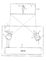
図1は、第1の実施形態における画像投影システム1の一例を示す構成図である。画像投影システム1は、投影対象に対して所望の映像コンテンツを構成する画像を投影するプロジェクションマッピングを実施する。画像投影システム1は、投影対象(例えば人物2)に対して動画像を投影できる。人物2は、例えば、ダンサー、運動選手などである。人物2は、変化する人物(動物体)でもよいし、変化しない人物(静止物体)でもよい。
(First embodiment)
[Configuration of image projection system]
FIG. 1 is a configuration diagram illustrating an example of an
画像投影システム1は、赤外線投影装置3、撮像装置5、及び演算装置6を備える。赤外線投影装置3は、人物2を含む投影対象に向けて赤外線画像を投影する。撮像装置5は、人物2を含む撮像対象に対して投影された赤外線画像及び可視光画像を撮像する。演算装置6は、赤外線投影装置3及び撮像装置5と通信可能に接続され、プロジェクションマッピングに係る各種処理を実行する。
The
赤外線投影装置3及び撮像装置5は、予め定められた位置にそれぞれ配置され得る。赤外線投影装置3は、所定の空間的な投影範囲PAに対して撮像する。投影範囲PAは固定である。撮像装置5は、所定の空間的な撮像範囲CAに含まれる被写体を撮像する。撮像範囲CAは固定である。投影範囲PAは、撮像範囲CAを含む。
The
赤外線投影装置3は、出射部10と、赤外線光源(IR光源)11と、DMD(Digital Mirror Device)12と、制御基板やプロセッサおよびメモリと、を備える。メモリには、赤外線投影装置3における各種の動作命令をプロセッサに実行させるプログラムが格納されている。出射部10は、投射レンズ等のレンズ系を含む。赤外線光源11は、赤外領域の光を発する赤外線LED(Light Emitting Diode)を備える。
The
DMD12は、赤外線光源11からの光を投射レンズに向けて選択的に反射することにより、動画又は静止画を含む所望の赤外線画像を形成する。DMD12は、液晶タイプの投影と比較すると、デジタル的にコントロール可能である。そのため、DMD12は、高精度に光を調整できるデジタル信号との親和性が高い。制御基板やプロセッサは、赤外線光源11やDMD12の動作を制御する。
The
赤外線光源11としては、所望の輝度を達成可能な場合、LEDに限らずレーザ等の他の光源を採用できる。
As the
赤外線投影装置3は、非可視光を用いた画像投影装置の一例である。非可視光の画像投影装置は、赤外線に限らず紫外線等の他の光を用いて、非可視光画像を投影してもよい。非可視光は、例えば、人に視認されない不可視光又はそれに準ずる光であって、実空間でのコンテンツ画像の視認に大きな影響を及ぼさない光である。
The
撮像装置5は、赤外線画像及び可視光画像の撮像に適したデジタルビデオカメラである。撮像装置5は、赤外線の波長領域(IR波長領域)及び可視光の波長領域に感度を有するイメージセンサを備える。イメージセンサは、例えば、近赤外線の波長領域(NIR(Near InfraRed)波長領域)の感度が高くされる。尚、撮像装置5は、動画を撮像してもよいし、静止画を撮像してもよい。
The
撮像装置5は、可視光カットフィルタ19を備える。可視光カットフィルタ19は、撮像装置5の対物レンズの外側(人物2側)に配置される。可視光カットフィルタ19は、図1に示すように着脱自在であり、赤外線画像を撮像するときに取り付けられ、可視光画像を撮像するときに取り外される。
The
可視光カットフィルタ19は、画像投影システム1のユーザにより手作業で着脱されてもよい。可視光カットフィルタは、撮像装置5にフィルタ駆動装置を付設することにより、自動で着脱されてもよい。フィルタ駆動装置は、可視光カットフィルタ19を撮像装置5の対物レンズに装着する装着位置と、対物レンズから離間する解除位置と、の間で変位させる。
The visible light cut
演算装置6は、例えば、PC(Personal Computer)やサーバ装置である。演算装置6は、例えば、通信デバイス、メモリ、プロセッサを備える。通信デバイスは、他の装置(例えば赤外線投影装置3、撮像装置5)との間で、無線又は有線によりデータを通信する。メモリは、各種データを記憶する。プロセッサは、例えば、CPU(Central Processing Unit)、DSP(Digital Signal Processor)、又はGPU(Graphical Processing Unit)を含む。プロセッサは、後述するキャリブレーション、カメラ座標及びプロジェクタ座標の変換、赤外線を用いたコンテンツ画像の投影、等を実施する。すなわちメモリには、演算装置6における各種の動作命令をプロセッサに実行させるプログラムが格納されている。
The
図2は、画像投影システム1の動作概要を示す説明図である。後に詳述するように、画像投影システム1では、赤外線投影装置3は、所定の複数のパターン(フレーム)から構成されるパターン画像を、赤外線画像として、投影範囲PA(所定の投影面)に照射する。撮像装置5は、撮像範囲CAに含まれる投射されたパターン画像を撮像する。この場合、撮像装置5は、可視光カットフィルタを介してパターン画像を撮像する。
FIG. 2 is an explanatory diagram showing an outline of the operation of the
演算装置6は、赤外線投影装置3により投影されたパターン画像(投影パターン画像)と撮像装置5により撮像されたパターン画像(撮像パターン画像)とに基づき、キャリブレーションする。キャリブレーションでは、演算装置6は、投影パターン画像と撮像パターン画像との位置関係を基に、撮像装置5が用いるカメラ座標系の座標(カメラ座標)と赤外線投影装置3が用いるプロジェクタ座標系の座標(プロジェクタ座標)とを変換するための変換テーブルを生成する。キャリブレーションにより、画像投影システム1は、赤外線投影装置3により投影された画像(投影画像)及び撮像装置5により撮像された画像(撮像画像)における各画素を対応付けできる。投影画像は、例えば投影されるコンテンツ画像である。キャリブレーションにより得られる各画素間の変換パラメータを含む変換テーブルは、赤外線投影装置3による投影画像の投影位置の補正に用いられる。
The
キャリブレーション後、撮像装置5は、可視光カットフィルタ19を介さずに、撮像範囲CAに所在する人物2を含む被写体を撮像する。演算装置6は、人物2に含まれる顔領域2Aを検出する。検出された顔領域2Aの位置はカメラ座標で示される。そのため、演算装置6は、検出された顔領域2Aの位置を、変換テーブルを基に、プロジェクタ座標に変換する。赤外線投影装置3は、プロジェクタ座標で表現された顔領域2Aの位置を基に、コンテンツ画像(例えば警告画像)を、顔領域2Aの全体に重複するように投影する。
After the calibration, the
これにより、画像投影システム1は、赤外線投影装置3と撮像装置5とが異なる位置に配置された場合でも、カメラ座標とプロジェクタ座標とを対応させて、撮像対象の人物2の顔領域に対して、コンテンツ画像を投影できる。従って、画像投影システム1は、撮像対象の人物2の特定の領域である顔に合わせて警告画像を重畳できる。よって、撮像画像の確認者は、撮像画像を確認しても、人物2の顔の特定が困難となる。
Thereby, even when the
[投影パターン画像の具体例]
図3は、投影パターン画像の一例を示す説明図である。投影パターン画像は、所定の画素数(例えば、1024×768画素)を有するDMD12のX座標及びY座標をグレイコード化した各ビットをマンチェスタ符号化し、白黒の2値画像として表すことにより得られる。ここでは、二次元空間コード化法に従って、投影パターン画像と撮像パターン画像とを用いて、プロジェクタ座標での位置情報とカメラ座標での位置情報とを対応付けることを例示する。
[Specific examples of projected pattern images]
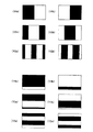
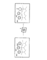
FIG. 3 is an explanatory diagram showing an example of a projection pattern image. The projection pattern image is obtained by Manchester-encoding each bit obtained by gray-coding the X and Y coordinates of the
例えば、X座標、Y座標ともに10ビットが割り当てられることにより座標情報がコード化される。図3では、X座標は、左右方向での位置を示す座標であり、Y座標は、上下方向での位置を示す座標である。図2では、X4a及びX4bは、それぞれX座標の最上位ビットである9ビット目を示すパターン画像及びその補完的な画像として輝度反転させたパターン画像である。X3a及びX3bは、それぞれX座標の8ビット目を示すパターン画像及びその補完的な画像として輝度反転させたパターン画像である。X2a及びX2bは、それぞれX座標の7ビット目を示すパターン画像及びその補完的な画像として輝度反転させたパターン画像である。 For example, coordinate information is coded by assigning 10 bits to both the X coordinate and the Y coordinate. In FIG. 3, the X coordinate is a coordinate indicating a position in the left-right direction, and the Y coordinate is a coordinate indicating a position in the vertical direction. In FIG. 2, X4a and X4b are a pattern image showing the ninth bit, which is the most significant bit of the X coordinate, and a pattern image whose luminance is inverted as its complementary image. X3a and X3b are a pattern image indicating the eighth bit of the X coordinate and a pattern image whose luminance is inverted as a complementary image thereof. X2a and X2b are a pattern image showing the seventh bit of the X coordinate and a pattern image whose luminance is inverted as a complementary image thereof.
また、図3では、Y4a及びY4bは、それぞれY座標の最上位ビットである9ビット目を示すパターン画像及びその補完的な画像として輝度反転させたパターン画像である。Y3a及びY3bは、それぞれY座標の8ビット目を示すパターン画像及びその補完的な画像として輝度反転させたパターン画像である。Y2a及びY2bは、それぞれY座標の7ビット目を示すパターン画像及びその補完的な画像として輝度反転させたパターン画像である。 In FIG. 3, Y4a and Y4b are a pattern image showing the ninth bit, which is the most significant bit of the Y coordinate, and a pattern image whose luminance is inverted as its complementary image. Y3a and Y3b are a pattern image indicating the eighth bit of the Y coordinate and a pattern image whose luminance is inverted as a complementary image thereof. Y2a and Y2b are a pattern image showing the seventh bit of the Y coordinate and a pattern image whose luminance is inverted as its complementary image.
図示は省略するが、X座標、Y座標ともに10ビットが割り当てられる場合、X座標、Y座標ともに、0ビット目を示すパターンまで合計40枚のパターンが設定される。各画素の濃度情報は、相互に補完的な画像対の差信号に基づいて、ノイズ除去が図られる。 Although illustration is omitted, when 10 bits are assigned to both the X coordinate and the Y coordinate, a total of 40 patterns are set up to the pattern indicating the 0th bit for both the X coordinate and the Y coordinate. The density information of each pixel is noise-removed based on mutually complementary image difference signals.
赤外線投影装置3は、このような20対の相互に補完的な画像対を含む投影パターン画像を、所定の時間内で順次人物2に投影する。撮像装置5が、投影パターン画像を撮像して撮像パターン画像を生成する。演算装置6は、投影パターン画像と撮像パターン画像とを比較する。これにより、演算装置6は、投影画像における各画素と撮像画像における各画素とを対応づけできる。また、演算装置6は、変化する人物2を追跡する処理を実行できる。
The
尚、ここでは1024×768画素であり、画像パターンの数が40枚(40フレーム)であることを例示したが、画像パターンの数は、解像度や所望する精度によって変化する。また、撮像装置5と赤外線投影装置3との設置条件によっては、Y座標又はX座標のいずれか一方を撮像装置5と赤外線投影装置3とで固定的に対応づけられてもよい。また、カメラ座標系とプロジェクタ座標系とのずれが投影範囲PA及び撮像範囲CAにおける狭い範囲に限定されて設定されてもよい。これにより、画像投影システム1は、X座標又はY座標のいずれか一方の座標コードを削減し、又は大幅に削減できる。
In this example, the number of image patterns is 1024 × 768 pixels and the number of image patterns is 40 (40 frames). However, the number of image patterns varies depending on resolution and desired accuracy. Further, depending on the installation conditions of the
[演算装置の構成]
図4は、演算装置6の機能構成例を示すブロック図である。
[Configuration of arithmetic unit]
FIG. 4 is a block diagram illustrating a functional configuration example of the
演算装置6は、パターン生成部21、画像出力部22、画像入力部23、パターン復号部24、フレームメモリ部25、コード復号用メモリ部26、座標変換部27、コンテンツ生成部30、コンテンツメモリ部31、及び顔検出処理部32を備える。
The
パターン生成部21は、図3に例示した投影パターン画像を記憶する。パターン生成部21は、投影パターン画像を構成する各パターンの情報を、所定のタイミングで画像出力部22に向けて順次出力する。
The
画像出力部22は、投影パターン画像の各パターンに対応する画像信号を赤外線投影装置3に供給する。画像出力部22は、投影パターン画像の画像出力のタイミングを画像入力部23に伝達する。
The
画像入力部23は、画像出力部22とタイミングを同期させて撮像するように、撮像装置5を制御する。画像入力部23は、撮像装置5により撮像された撮像画像を取得し、入力する。撮像画像の取得は、例えば有線又は無線の通信により行われる。有線通信は、例えば、同軸ケーブル、PLC(Power Line Communication)、DECT(Digital Enhanced Cordless Telecommunication)を含む。無線通信は、例えば、無線LAN(Local Area Network)、Bluetooth(登録商標)を含む。撮像画像は、例えば、撮像パターン画像、人物2等の被写体を含む画像、を含む。また、撮像画像は、赤外線画像(例えば投影パターン画像)、可視光画像、を含む。画像入力部23は、入力した撮像パターン画像をパターン復号部24に送る。画像入力部23は、人物2を含む被写体を含む撮像画像を、顔検出処理部32へ送る。
The
パターン復号部24は、画像入力部23からの撮像パターン画像に関し、補完的な画像対の1つ目(ここでは他方という)を取得した場合、フレームメモリ部25に記憶しておく。パターン復号部24は、画像入力部23からの撮像パターン画像に関し、補完的な画像対の2つ目(ここでは一方という)を取得した場合、補完的な画像対の一方と、フレームメモリ部25に先に記憶された補完的な画像対の他方とのフレーム間の差分を計算する。これにより、画像投影システム1は、環境光等の影響を抑制して、撮像パターン画像の画素値(ここでは、「0」及び「1」の2値)を容易に判別できる。
When the
コード復号用メモリ部26には、撮像装置5の画素毎(撮像画像の画素毎)に書き込み領域が設けられている。パターン復号部24は、上記差分を計算した後、グレイコード化した座標データの各ビット値を、コード復号用メモリ部26における各画素に対応する書き込み領域にビット単位で書き込む。パターン復号部24は、この処理を画像パターンの数(例えば40フレーム)分実行し、撮像装置5の撮像画像の各画素(カメラ座標系)に対応する赤外線投影装置3の赤外線画像の各画素(プロジェクタ座標系)のX座標及びY座標のそれぞれを示す10bitの値を得る。パターン復号部24は、この10Bitの値をコード復号用メモリ部26に書き込む。
In the code
このようにして、コード復号用メモリ部26には、最終的に投影画像(例えば投影パターン画像)と撮影画像(撮像パターン画像)との各画素の対応情報が格納される。パターン復号部24により補完的な画像対が1つ処理される毎に、最新の画素の対応情報が得られる。つまり、コード復号用メモリ部26は、プロジェクタ座標とカメラ座標との対応情報を画素毎に保持する。この各画素の対応情報は、コード復号用メモリ部26の変換テーブル26Tに含まれる。
In this way, the code
顔検出処理部32は、画像入力部23からの撮像画像に含まれる人物2の顔領域2Aを検出する。顔領域2Aの検出は、例えばViola−Jones法により実施される。顔検出処理部32は、検出された人物2の顔領域2Aの位置情報、つまり顔領域2Aの座標(カメラ座標)を、座標変換部27へ送る。
The face
座標変換部27は、変換テーブル26Tに保持された対応情報に基づき、撮像画像の各画素の位置を、カメラ座標からプロジェクタ座標に変換する。つまり、座標変換部27は、顔検出処理部32からの顔領域2Aのカメラ座標を受け取り、変換テーブル26Tを参照して、顔領域2Aのカメラ座標をプロジェクタ座標に変換する。
The coordinate
コンテンツメモリ部31には、人物2に投影されるべき画像(例えばコンテンツ画像)の素材となるデータ(例えば文字データ、テクスチャデータ、動画データ、メッシュデータ、シェーダープログラム、等)が記憶される。このデータは、コンテンツ生成部30からの要求に応じてコンテンツ生成部30に読み込まれる。
The
コンテンツ生成部30は、キャリブレーション情報つまり変換テーブル26Tの対応情報に基づいて、人物2の顔領域2Aにマッピングされるべきコンテンツ画像を生成する。この投影用のコンテンツ画像は、画像出力部22に向けて順次出力される。コンテンツ画像は、例えば、カメラ撮像者に対して警告したりカメラによる撮像を妨害したりするための警告画像を含む。従って、警告画像は妨害画像とも言える。
The
コンテンツ生成部30は、座標変換部27からの顔領域2Aのプロジェクタ座標の情報を受け取る。コンテンツ生成部30は、顔領域2Aのプロジェクタ座標に基づいて、コンテンツ画像が投影される位置の情報(投影位置情報)を生成する。例えば、コンテンツ生成部30は、顔領域2Aの中心座標とコンテンツ画像の中心座標とを一致させて、投影位置情報を生成する。
The
コンテンツ生成部30は、コンテンツ画像が投影されるサイズ(コンテンツサイズ)の情報を生成する。コンテンツ生成部30は、コンテンツサイズを、顔領域2Aと同等又は顔領域2Aよりも広くする。つまり、顔領域2Aは、赤外線投影装置3により投影されたコンテンツ画像により覆われる状態となる。コンテンツサイズは、顔領域2Aと同等又は顔領域2Aよりも広くすれば、演算装置6の操作部を介してユーザにより入力されてもよい。
The
コンテンツ生成部30は、コンテンツ画像が投影される形状(コンテンツ形状)の情報を生成する。コンテンツ生成部30は、顔領域2Aに対応するコンテンツ画像の形状を、顔領域2Aの検出形状と同じにしてもよいし、顔領域2Aの検出形状からより簡易な形状(例えば円形状、矩形状、その他の多角形状)でもよい。尚、コンテンツ形状は、特別に決定されずに、コンテンツメモリ部31に予め保持されたコンテンツ画像の形状でもよい。この場合、コンテンツ生成部30によりコンテンツ形状の情報は生成されない。
The
画像出力部22は、コンテンツ画像、投影位置情報、コンテンツサイズの情報、コンテンツ形状の情報をコンテンツ生成部30から受け取り、コンテンツ画像、投影位置情報、コンテンツサイズの情報、コンテンツ形状の情報に基づく赤外線画像信号を、赤外線投影装置3に供給する。
The
尚、演算装置6は、例えば汎用のハードウェアを備えたコンピュータからなる。演算装置6は、例えば、所定の制御プログラムに基づき情報処理を実行するプロセッサ、プロセッサのワークエリア等として機能する揮発性メモリ、プロセッサが実行する制御プログラムやデータを格納する不揮発性メモリ、等を含んで構成される。演算装置6は、ASIC(Application Specific Integrated Circuit)やFPGA(Field Programmable Gateway)からなる集積回路を備えた構成でもよい。また、後述する第3の実施形態のように、演算装置6の機能の少なくとも一部と同様の機能を、赤外線投影装置3及び撮像装置5の少なくとも1つに付加した構成も可能である。
Note that the
[画像投影システムの動作]
次に、画像投影システム1の動作例について説明する。
[Operation of image projection system]
Next, an operation example of the
図5は、画像投影システム1のキャリブレーション処理の一例を示すフローチャートである。画像投影システム1は、赤外線投影装置3によるコンテンツ画像の投影前(例えば、赤外線投影装置3におけるズーム設定やフォーカス設定の変更時又は撮像装置5のズーム設定やフォーカス設定の変更時)に、キャリブレーション処理を実行する。
FIG. 5 is a flowchart illustrating an example of the calibration process of the
まず、可視光カットフィルタ19が撮像装置5の対物レンズに装着される(S11)。
First, the visible light cut
赤外線投影装置3は、投影パターン画像を投影範囲PAに投射する(S12)。撮像装置5は、撮像範囲CAでその投影パターン画像を撮像し、撮像パターン画像を得る(S13)。ここでは、撮像装置5には、可視光カットフィルタ19が取り付けられており(即ち、可視光カットが有効な状態にあり)、撮像装置5は、可視光領域を遮断して赤外領域を透過する。つまり、撮像画像としての撮像パターン画像は、赤外線画像となる。撮像装置5は、撮像パターン画像を演算装置6へ送る。
The
演算装置6では、画像入力部23が、演算装置6からの撮像パターン画像を取得し、パターン復号部24へ送る。パターン復号部24は、画像入力部23からの撮像パターン画像に基づき、赤外線投影装置3により投影される赤外線画像(投影画像)と撮像装置5により撮像される撮像画像との各画素を対応づける(S14)。パターン復号部24は、この各画素の対応付けの情報を含む変換テーブル26Tを生成する。変換テーブル26Tは、コード復号用メモリ部26に保持される。
In the
変換テーブル26Tの生成が終了すると、撮像装置5の可視光カットフィルタ19が解除される。つまり、撮像装置5の対物レンズから可視光カットフィルタ19が取り外される(S15)。これにより、キャリブレーション処理が終了し、撮像装置5は、可視光による撮像が可能となる。
When the generation of the conversion table 26T ends, the visible light cut
図5に示したキャリブレーション処理によれば、撮像装置5による撮像範囲CAと赤外線投影装置3による投影範囲PAが異なる場合でも、変換テーブル26Tを用いて、カメラ座標とプロジェクタ座標とで対応付けが可能となる。したがって、画像投影システム1は、厳密に投影範囲PAと撮像範囲CAとを位置合わせする手間を低減できる。また、画像投影システム1は、変換テーブル26Tを用いて自動でカメラ座標とプロジェクタ座標との対応付けが可能であるので、手動による調整誤差を低減でき、キャリブレーションの精度を向上できる。
According to the calibration processing shown in FIG. 5, even when the imaging range CA by the
図6は、人物2の顔領域2Aを考慮したコンテンツ画像(警告画像)の投影処理の一例を示すフローチャートである。人物2の顔領域2Aを考慮したコンテンツの投影処理は、図5に示したキャリブレーション処理後に実施される。
FIG. 6 is a flowchart illustrating an example of a content image (warning image) projection process in consideration of the
まず、撮像装置5により人物2を含む撮像範囲を撮像する(S21)。撮像装置5は、撮像された画像(撮像画像)を演算装置6へ送る。
First, an imaging range including the
演算装置6では、画像入力部23が撮像画像を撮像装置5から取得し、顔検出処理部32へ送る。顔検出処理部32は、撮像画像に含まれる人物2の顔領域2Aを検出する(S22)。顔検出処理部32は、検出された顔領域2Aの位置情報(ここではカメラ座標系での座標情報)を座標変換部27へ出力する。
In the
座標変換部27は、変換テーブル26Tを参照し、画素毎に、顔領域2Aのカメラ座標プロジェクタ座標に変換する(S23)。座標変換部27は、顔領域2Aのプロジェクタ座標の情報をコンテンツ生成部30へ送る。
The coordinate
そして、コンテンツ生成部30は、コンテンツメモリ部31からコンテンツ画像を取得し、コンテンツ画像を顔領域2Aに基づいて加工する(S24)。例えば、コンテンツ生成部30は、顔領域2Aのサイズに応じて、コンテンツ画像のサイズを変更する。コンテンツ生成部30は、顔領域2Aの同サイズ又は顔領域2Aよりも大きなサイズのコンテンツ画像を生成する。顔領域2Aの範囲がコンテンツ画像の範囲と重複し、顔領域2Aにより隠れれば、コンテンツ画像の形状は任意である。コンテンツ生成部30は、顔領域2Aのプロジェクタ座標に基づいて、コンテンツ画像が顔領域2Aの全体と重複する投影位置に係るコンテンツ画像の投影位置情報を生成する。コンテンツ生成部30は、生成された(例えば加工された)コンテンツ画像及びコンテンツ画像の投影位置情報を画像出力部22へ送る。画像出力部22は、コンテンツ生成部30からのコンテンツ画像及びコンテンツ画像の投影位置情報を赤外線投影装置3へ送る。尚、コンテンツのサイズ情報や形状情報が赤外線投影装置3へ送られてもよい。
Then, the
赤外線投影装置3は、演算装置6からのコンテンツ画像及びコンテンツ画像の投影位置情報を取得する。赤外線投影装置3は、顔領域2Aのプロジェクタ座標系での座標情報に基づく位置に、決定されたコンテンツサイズ及びコンテンツ形状でコンテンツ画像を投影する(S25)。赤外線投影装置3は、例えば、顔領域2Aの中心座標とコンテンツ画像の中心座標とを一致させて、コンテンツ画像を投影する。
The
図6に示した人物2の顔領域2Aを考慮した警告画像の投影処理によれば、画像投影システム1は、顔領域2Aのカメラ座標位置に対して、プロジェクタ座標位置を用いて警告画像を投影できる。従って、顔領域2Aは、警告画像により覆われる。そのため、撮像装置5が人物2の顔領域2Aを含む撮像範囲を撮像しても、警告画像が撮像される。従って、この撮像画像を確認するユーザは、警告画像により顔領域2Aに実空間では存在する人物2の顔を確認不能となる。一方、顔領域2A以外である撮像画像の領域の一部は、ユーザによって確認可能である。
According to the projection processing of the warning image in consideration of the
従って、画像投影システム1は、人物2のプライバシーを保護できる。また、画像投影システム1は、人物2が演劇中、歌唱中である等、著作権等を考慮すべき状態であっても、著作権を適切に保護できる。更に、画像投影システム1は、撮像装置5により、ユーザの希望に応じて顔領域2A以外の領域を視認可能に撮像できる。
Therefore, the
尚、撮像装置5は、人物2を含む被写体を常時撮像してもよいし、定期的に撮像してもよいし、ユーザやタイマに指定された時刻に撮像してもよい。撮像間隔が短い程、人物2の動きへの追従性が高くなる。よって、人物2の顔領域2Aに対する警告画像の投射位置の追従性が高くなる。
Note that the
[ユースケース]
次に、本実施形態の画像投影システム1のユースケースについて説明する。ユースケースとしては、例えば、下記に示すユースケース1,2が考えられる。
[Use Case]
Next, a use case of the
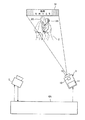
図7は、ユースケース1を説明するための模式図である。図7では、赤外線投影装置3は、人物2(ここでは、舞台40の出演者)の顔領域2Aに、コンテンツ画像として警告画像41を投影する。これにより、撮影禁止の会場において、観客が舞台40上の出演者等を無断で撮影した場合でも、警告画像41が撮像画像に映り込み、撮影が阻害される。また、警告画像41が撮像画像に映り込むことで、顔領域2Aの視認性が低下する。図7では、警告画像41が円形で投射されることを例示したが、警告画像41は、顔領域2Aを覆えばよく、他の形状でもよい。
FIG. 7 is a schematic diagram for explaining
尚、赤外線投影装置3は、近赤外領域の比較的強い光によって赤外線画像を投影することにより、可視光を撮影するためのカメラを観客が撮影に用いた場合でも、撮影された可視光画像に対して警告画像41による悪影響を及ぼすことが可能である。カメラのイメージセンサが可視光よりも波長の長い近赤外領域に対してもある程度感度を有するためである。
The
図8は、ユースケース2を説明するための模式図である。図8は、図7と比較すると、
警告画像41としては、所望の文字情報(ここでは、観客に対する警告的なメッセージ「撮影禁止!」)を含む警告画像41を用いている。これにより、画像投影システム1は、無断撮影を実施した観客に対して効果的に注意喚起できる。図8においても、顔領域2Aに対してコンテンツ画像が投影され、顔領域2Aが警告画像41で覆われている。従って、画像投影システム1は、警告画像41によりプライバシーや著作権等を適切に保護しつつ、ユーザによる警告画像41に覆われていない撮像画像の一部の確認も可能とする。
FIG. 8 is a schematic diagram for explaining
As the
図9は、ユースケース3を説明するための模式図である。図9は、撮影禁止のコンサート会場で画像投影システム1を用いることを想定している。例えば、光強度の大きい赤外光を照射可能な赤外線投影装置3が、顔領域2Aに重複する警告画像41としてのジャミングコンテンツを投影する。この場合、観客の肉眼つまり実空間では警告画像41を視認不能であるので、パフォーマーの演技を通常通り確認できる。一方、スマートフォンが備えるカメラにより撮像すると、撮像画像内にパフォーマーの顔領域2Aに対して赤外線投影装置3により警告画像41が重畳されているので、パフォーマーの顔を確認不能となる。
FIG. 9 is a schematic diagram for explaining
このように、画像投影システム1によれば、シーンに応じて、ジャミングデータを投影可能である。従って、画像投影システム1は、カメラによるパフォーマーによるパフォーマンスの盗撮を抑制できる。また、パフォーマーの顔以外の部分は撮像画像においても確認可能であるので、プライバシーを保護しながら、ユーザが注目する箇所を確認できる。
Thus, according to the
尚、コンテンツ生成部30は、撮像画像における顔領域2Aの各画素値を白黒反転して、警告画像41を生成してもよい。これにより、顔領域2Aの画素値が平滑化され、画像の特徴が希薄化される。また、警告画像41として、広告画像やコピー禁止の文字画像を用いてもよい。また、画像投影システム1は、特定の時間区間(例えばコンサートがテレビ放映される際のCM中)については、警告画像41を顔領域2Aに重畳しないように制御してもよく、例えば赤外線投影装置3による警告画像41の投影を停止させてもよい。
The
[作用効果等]
このように、本実施形態の画像投影システム1は、赤外線を用いて画像を投影する赤外線投影装置3と、撮像装置5と、演算装置6と、を備える。演算装置6は、赤外線投影装置3により投影された所定のパターン画像と、撮像装置5により撮像された所定のパターン画像と、の位置関係を基に、撮像装置5が用いるカメラ座標と赤外線投影装置3が用いるプロジェクタ座標とを変換するための変換情報を生成する。撮像装置5は、人物2を含む被写体を撮像する。演算装置6は、人物2における特定の領域のカメラ座標に係る位置を示す第1の位置を検出する。演算装置6は、変換情報を基に、第1の位置の情報を、特定の領域のプロジェクタ座標に係る位置を示す第2の位置の情報に変換する。赤外線投影装置3は、第2の位置の情報を基に、特定の領域の全領域に重複して警告画像を投影する。尚、赤外線は、非可視光の一例である。赤外線投影装置3は、画像投影装置の一例である。
[Effects]
As described above, the
これにより、画像投影システム1は、人物2における特定の領域を検出し、人物2の特定の領域を考慮して、非可視光の一例である赤外線を用いて警告画像41を投影できる。そのため、肉眼では人物の特定の領域を把握しながら、撮像画像では特定の領域を確認不能となり、人物2のプライバシーや人物2が出演する舞台や衣装等の著作権を保護できる。一方、人物2の特定の領域以外を確認することは可能である。従って、画像投影システム1は、撮像画像におけるプライバシーや著作権等を適切に保護しつつ、撮像画像における一部の画像領域に限定して視認性を低減できる。
Thereby, the
また、人物2における特定の領域が、人物2の顔領域でもよい。
Further, the specific area in the
これにより、画像投影システム1は、処理時間の比較的短い検出処理である顔領域の検出処理を実施でき、リアルタイム性を向上できる。よって、例えば人物2が舞台上で動き回る場合でも、赤外線投影装置3は、顔領域2Aの動きに対する追従性を向上して、警告画像を投影できる。
As a result, the
また、演算装置6は、人物2の顔領域2Aのサイズを基に、警告画像のサイズを制御してもよい。
Further, the
人物2が移動すると、撮像装置5と人物2との距離が変化し、人物2の顔領域2Aの大きさが変化し、撮像画像内の顔領域2Aの大きさが変化することがある。この場合でも、画像投影システム1は、警告画像41のサイズを調整して、顔領域2Aの全領域を警告画像41で覆うことが可能である。また、画像投影システム1は、警告画像41のサイズを調整できるので、予めコンテンツメモリ部31等に保持される警告画像41のサイズを小さくでき、警告画像41を保存するためのデータ量を小さくできる。よって、画像投影システム1は、コンテンツメモリ部31等の限られたメモリ空間を有効活用できる。
When the
(第2の実施形態)
第1の実施形態では、人物2の顔領域2Aの位置にコンテンツ画像を投影することを例示した。第2の実施形態では、人物2の顔領域2Aの位置とは異なる位置に、コンテンツ画像を投影することを例示する。尚、本実施形態では、第1の実施形態と異なる事項を主に説明し、第1の実施形態と同様の事項については、その説明を省略又は簡略化する。
(Second Embodiment)
In the first embodiment, the content image is projected onto the
図10は、演算装置6Aの機能構成例を示すブロック図である。演算装置6Aは、第1の実施形態の演算装置6と比較すると、コンテンツ生成部30の代わりにコンテンツ生成部30Aを備える。
FIG. 10 is a block diagram illustrating a functional configuration example of the
コンテンツ生成部30Aは、キャリブレーション情報に基づいて、人物2の顔領域2Aを避けてマッピングされるべきコンテンツ画像を生成する。この投影用のコンテンツ画像は、画像出力部22に向けて順次出力される。コンテンツ画像は、例えば、人物2が置かれたシーンを装飾するための装飾画像を含む。
The
コンテンツ生成部30Aは、コンテンツ画像が投影されるサイズ(コンテンツサイズ)の情報を生成する。コンテンツサイズは、顔領域2Aと同等でもよいし、顔領域2Aよりも大きくてもよいし、顔領域2Aよりも小さくてもよい。コンテンツ生成部30Aは、コンテンツサイズを、顔領域2Aや人物2が不在である領域に収まるように、各特徴領域の位置情報に応じて自動的に生成してもよい。コンテンツサイズは、演算装置6の操作部を介してユーザにより入力されてもよい。
The
コンテンツ生成部30Aは、座標変換部27からの顔領域2Aのプロジェクタ座標の情報を受け取る。コンテンツ生成部30Aは、顔領域2Aのプロジェクタ座標に基づいて、コンテンツ画像の投影位置情報を生成する。例えば、コンテンツ生成部30Aは、顔領域2Aのプロジェクタ座標とコンテンツ画像の座標とが重複部分を有しないように、投影位置情報を生成する。
The
図11は、人物2の顔領域2Aを考慮したコンテンツ画像(装飾画像)の投影処理の一例を示すフローチャートである。人物2の顔領域2Aを考慮したコンテンツ画像の投影処理は、前述した図5に示したキャリブレーション処理後に実施される。図11では、図6の処理と同様の処理については、同一のステップ番号を付し、その説明を省略又は簡略化する。
FIG. 11 is a flowchart illustrating an example of a content image (decoration image) projection process in consideration of the
コンテンツ生成部30Aは、コンテンツメモリ部31からコンテンツ画像(装飾画像)を取得し、コンテンツ画像を顔領域2Aに基づいて加工する(S24A)。例えば、コンテンツ生成部30Aは、コンテンツ画像のサイズを、コンテンツ画像が顔領域2Aと重複しないように調整する。コンテンツ生成部30Aは、コンテンツ形状を加工してもよい。コンテンツ生成部30Aは、顔領域2Aのプロジェクタ座標に基づいて、コンテンツ画像が顔領域2Aと重複しない投影位置に係るコンテンツ画像の投影位置情報を生成する。コンテンツ生成部30Aは、生成された(例えば加工された)コンテンツ画像及びコンテンツ画像の投影位置情報を画像出力部22へ送る。画像出力部22は、コンテンツ生成部30Aからのコンテンツ画像及びコンテンツ画像の投影位置情報を赤外線投影装置3へ送る。尚、コンテンツのサイズ情報や形状情報が赤外線投影装置3へ送られてもよい。
The
赤外線投影装置3は、演算装置6からのコンテンツ画像及びコンテンツ画像の投影位置情報を取得する。赤外線投影装置3は、コンテンツ画像の投影位置情報に基づく投影位置に、決定されたコンテンツサイズ及びコンテンツ形状でコンテンツ画像(装飾画像)を投影する(S25A)。
The
図11に示した人物2の顔領域2Aを考慮した装飾画像の投影処理によれば、画像投影システム1は、顔領域2Aのカメラ座標位置を避けて、プロジェクタ座標位置を用いて装飾画像を投影できる。従って、顔領域2Aは、装飾画像により覆われない。そのため、撮像装置5が人物2の顔領域2Aを含む撮像範囲CAを撮像しても、顔領域2Aが装飾画像で覆われることなく、人物2の顔及び装飾画像が撮像される。従って、この撮像画像を確認するユーザは、人物2の顔とともに実空間では存在しない装飾画像を確認可能となる。
According to the decoration image projection processing in consideration of the
従って、画像投影システム1は、人物2に発生する各種イベント(例えば冠婚葬祭、アミューズメントパークでの演出)を彩ることができる。また、画像投影システム1は、装飾された各種イベント中の人物2の顔領域2Aを覆うことなく、人物2の様子や表情を撮像画像に収めることができる。よって、将来イベントを振り返った際に、撮像画像を確認した確認者が、イベント当時の様子や人物2の状況を回想し易くなる。
Therefore, the
次に、本実施形態の画像投影システム1のユースケースについて説明する。ユースケースとしては、例えば、下記に示すユースケース4,5が考えられる。
Next, a use case of the
図12は、ユースケース4を説明するための模式図である。赤外線投影装置3は、人物2の顔領域2Aと重複させずに、顔領域2Aの周辺に赤外線画像として装飾画像51を投影する。図12では、人物2(ここでは、結婚式の新郎・新婦)に対し、装飾画像51として、所望の文字及び図形を含む情報(ここでは、新郎・新婦に対するお祝いのメッセージ及び図形)を含む装飾画像51が投影された例を示している。これにより、画像投影システム1は、撮像装置5による撮影画像を現像(またはディスプレイ表示)した際に初めて視認可能となる装飾画像51によって、撮影者(結婚式の参加者等)に対して驚きや喜びを喚起できる。
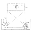
FIG. 12 is a schematic diagram for explaining use case 4. The
図13は、ユースケース5を説明するための模式図である。図13は、葬儀時に斎場で親族の集合記念写真を撮影するシーンを想定している。例えば、光強度の大きい赤外光を照射可能な赤外線投影装置3が、故人の像や個人又は遺族のコメントの情報を装飾画像51として照射する。装飾画像51は、遺族の各顔領域2Aと重複しない位置に照射される。この場合、実空間では装飾画像51を視認不能であるが、スマートフォンが備えるカメラにより撮像すると、撮像画像内で装飾画像51を視認可能となる。
FIG. 13 is a schematic diagram for explaining
また、コンテンツ生成部30Aは、装飾画像51の投影位置を顔領域2Aの位置に基づいて算出し、算出された投影位置に装飾画像51を投影してもよい。装飾画像51内のコメントの情報は、「今までありがとう」等の感謝のコメントでもよいし、故人に生前に聴取した所望のコメントでもよい。
The
ユースケース5の画像投影システム1によれば、装飾画像51を肉眼で視認不能であるので、実際の葬式イベントを滞りなく進行できる。また、将来的に撮像画像を確認して葬式イベントを回想した際には、遺族等の故人に対する思い入れを強くできる。また、画像投影システム1を用いることで、装飾画像51により葬式イベントを彩ることができる。画像投影システム1は、葬式イベントの付加価値として装飾画像51を含む撮像画像を斎場が提供することを可能とし、斎場の評価を高くできる。
According to the
図14は、ユースケース6を説明するための模式図である。図14は、テーマパークでのお化け屋敷において画像投影システム1を用いることを想定している。例えば、光強度の大きい赤外光を照射可能な赤外線投影装置3が、心霊関連の画像(例えばお化けの画像)を装飾画像51として投射する。この場合、実空間では装飾画像51を視認不能であるが、スマートフォンが備えるカメラにより撮像すると、撮像画像内で装飾画像51を視認可能となる。よって、このカメラは装飾画像51を含む心霊写真を撮像できる。
FIG. 14 is a schematic diagram for explaining the
また、コンテンツ生成部30Aは、装飾画像51の投影位置を顔領域2Aの位置に基づいて算出し、算出された投影位置に装飾画像51を投影してもよい。
The
ユースケース6の画像投影システム1によれば、お化け屋敷を訪れた人物2が、カメラによる撮像画像を確認することで、お化け屋敷内の実空間には存在しなかったお化けを確認することになり、一段と恐怖感を煽ることができる。従って、画像投影システム1は、スリル満点のアミューズメントシステムを提供できる。
According to the
尚、画像投影システム1は、コンテンツメモリ部31に多数のお化けのキャラクタに係る装飾画像51を保持することで、投影可能なお化けの種類を増大できる。また、コンテンツ生成部30Aが、装飾画像51を加工し、お化けのキャラクタを装飾してもよい。また、画像投影システム1は、装飾画像51が撮像画像内に含まれることで、テーマパークのゲストに対して物語のヒントを提供してもよい。
Note that the
このように、本実施形態の画像投影システム1は、赤外光を用いて画像を投影する赤外線投影装置3と、撮像装置5と、演算装置6Aと、を備える。演算装置6Aは、赤外線投影装置3により投影された所定のパターン画像と、撮像装置5により撮像された所定のパターン画像と、の位置関係を基に、撮像装置5が用いるカメラ座標と赤外線投影装置3が用いるプロジェクタ座標とを変換するための変換情報を生成する。撮像装置5は、人物2を含む被写体を撮像する。演算装置6Aは、人物2における特定の領域のカメラ座標に係る位置を示す第1の位置を検出する。演算装置6Aは、変換情報を基に、第1の位置の情報を、特定の領域のプロジェクタ座標に係る位置を示す第2の位置の情報に変換する。赤外線投影装置3は、第2の位置の情報を基に、特定の領域を避けて装飾画像51を投影する。
As described above, the
これにより、画像投影システム1は、人物2における特定の領域を検出し、人物2の特定の領域(例えば顔領域2A)を考慮して、非可視光の一例である赤外線を用いて装飾画像51を投影できる。そのため、肉眼では人物2をそのまま視認可能である一方、撮像画像では特定の領域以外の領域に装飾画像51を確認できる。よって、画像投影システム1は、撮像画像内の人物2の体験やその体験時の人物の様子、顔の表情等を装飾でき、人物2の思い出を彩ることができる。
As a result, the
(第3の実施形態)
第1,第2の実施形態では、演算装置6,6Aが別体として設けられることを例示した。第3の実施形態では、演算装置6,6Aが別体として設けられず、演算装置6,6Aが有する機能を赤外線投影装置3が有することを例示する。第3の実施形態では、主に、画像投影システムが、第1の実施形態のように、顔領域2Aに対して警告画像41を投影することを例示するが、第2の実施形態のように、顔領域2Aを避けて装飾画像51を投影してもよい。
(Third embodiment)
In the first and second embodiments, it is exemplified that the
図15は、画像投影システム1Bの一例を示す模式図である。画像投影システム1Bは、赤外線投影装置3B及び撮像装置5を備える。図15では、図1に示した第1,第2の実施形態における画像投影システム1と同様の構成については、その説明を省略又は簡略化する。
FIG. 15 is a schematic diagram illustrating an example of the
赤外線投影装置3Bは、出射部10、赤外線光源11、DMD12、コントローラ13、及びプロセッサ14、及び通信デバイス15を備える。コントローラ13は、例えばMEMS(Micro Electro Mechanical Systems)により形成され、赤外線光源11やDMD12の動作を制御する。通信デバイス15は、有線又は無線により撮像装置5と接続される。通信デバイス15は、例えば、無線LAN、Bluetooth(登録商標)を用いて、撮像装置5と無線通信し、撮像画像を取得する。
The
プロセッサ14は、例えばFPGA(Field Programmable Gate Array)により構成される。プロセッサ14は、演算装置6又は演算装置6Bとほぼ同様の機能を有する。つまり、プロセッサ14は、パターン生成部21B、画像出力部22B、画像入力部23B、パターン復号部24B、フレームメモリ部25B、コード復号用メモリ部26B、座標変換部27B、コンテンツ生成部30B、コンテンツメモリ部31B、及び顔検出処理部32Bを備える。
The
図16は、プロセッサ14の構成例を示すブロック図である。図16では、図4と比較すると、各構成部の符号の末尾に「B」を追加したが、これは演算装置6が有する構成とプロセッサ14が有する構成とを区別するために付したものであり、機能は同様である。尚、プロセッサ14の画像入力部23Bは、演算装置6の画像入力部23と異なり、通信デバイス15との間でデータを送受する。尚、プロセッサ14の画像出力部22Bは、演算装置6の画像出力部22と異なり、データの出力先は赤外線光源11となる。
FIG. 16 is a block diagram illustrating a configuration example of the
このように、本実施形態の赤外線投影装置3は、赤外線を用いて画像を投影する赤外線光源11と、撮像装置5により撮像された画像を取得する通信デバイス15と、赤外線光源11により投影された所定のパターン画像と、撮像装置5により撮像された所定のパターン画像と、の位置関係を基に、撮像装置5が用いるカメラ座標と赤外線投影装置3が用いるプロジェクタ座標とを変換するための変換情報を生成するプロセッサ14と、を備える。プロセッサ14は、撮像装置5により撮像された被写体に含まれる人物2における特定の領域のカメラ座標に係る位置を示す第1の位置を検出し、変換情報を基に、第1の位置の情報を、特定の領域のプロジェクタ座標に係る位置を示す第2の位置の情報に変換する。赤外線光源11は、第2の位置の情報を基に、特定の領域の全領域に重複して警告画像41を投影する。
As described above, the
尚、赤外線光源11は、投影部の一例である。通信デバイス15は、取得部の一例である。プロセッサ14は、処理部の一例である。
The infrared
これにより、赤外線投影装置3は、人物2における特定の領域を検出し、人物2の特定の領域を考慮して、非可視光の一例である赤外線を用いて警告画像41を投影できる。そのため、肉眼では人物2の特定の領域を把握しながら、撮像画像では特定の領域を確認不能となり、人物2のプライバシーや人物2が出演する舞台や衣装等の著作権等を保護できる。一方、人物2の特定の領域以外を確認することは可能である。従って、赤外線投影装置3は、撮像画像におけるプライバシーや著作権等を適切に保護しつつ、撮像画像における一部の画像領域に限定して視認性を低減できる。更に、赤外線投影装置3が、第1,第2の実施形態の演算装置6の機能を有することで、演算装置6を別体と設けることが不要となる。従って、演算装置6の設置スペースを削減でき、演算装置6に要するコストを低減できる。
Thereby, the
(他の実施形態)
以上のように、本開示における技術の例示として、第1〜第3の実施形態を説明した。しかし、本開示における技術は、これに限定されず、変更、置き換え、付加、省略などを行った実施形態にも適用できる。また、各実施形態を組み合わせてもよい。
(Other embodiments)
As described above, the first to third embodiments have been described as examples of the technology in the present disclosure. However, the technology in the present disclosure is not limited to this, and can also be applied to embodiments in which changes, replacements, additions, omissions, and the like are performed. Moreover, you may combine each embodiment.
第1〜第3の実施形態では、画像投影装置が、赤外線を用いて画像を投影することを例示したが、赤外線以外の非可視光(例えば紫外線)を用いて画像を投影してもよい。 In the first to third embodiments, it has been exemplified that the image projection apparatus projects an image using infrared rays, but the image may be projected using non-visible light (for example, ultraviolet rays) other than infrared rays.
第1,第3の実施形態では、撮像画像が複数存在する場合に、複数の顔領域2Aの全てに重複するようにコンテンツ画像を投影することを例示した。第2,第3の実施形態では、撮像画像が複数存在する場合に、複数の顔領域2Aの全てを避けて、つまり複数の顔領域2Aの全てと重複しないように、コンテンツ画像を投影することを例示した。この代わりに、赤外線投影装置3は、複数の人物2の顔領域2Aのうち特定の顔領域2Aに限定して、この顔領域2Aに重複するようにコンテンツ画像を投影してもよい。
In the first and third embodiments, when there are a plurality of captured images, the content image is projected so as to overlap all of the plurality of
つまり、撮像装置5により撮像された被写体は、複数の人物2を含んでもよい。赤外線投影装置3は、複数の人物2のうち特定の人物の顔領域2Aのプロジェクタ座標に係る位置を示す第2の位置に対して、警告画像を投影してもよい。
That is, the subject imaged by the
これにより、画像投影システム1は、撮像装置5による撮像を希望しない人物2と、撮像装置5による撮像を希望する人物2とが混在する場合でも、撮像装置5により撮像できる。この場合でも、画像投影システム1は、撮像を希望しない人物2の顔領域周辺を警告画像により隠すことができ、この人物2のプライバシーを適切に保護できる。
As a result, the
図17は、人物2が複数存在する場合の警告画像41の第1投影例を示す模式図である。図17では、特定の人物以外の一例としての撮像を希望する人物2A1が2人存在し、特定の人物の一例としての撮像を希望しない人物2A2が1人存在することを例示している。図17では、撮像を希望する人物2A1には警告画像41が投影されず、撮像を希望しない人物2A2には警告画像41が投影される。
FIG. 17 is a schematic diagram illustrating a first projection example of the
また、赤外線投影装置3は、複数の人物2のうち特定の人物以外の人物の顔領域2Aのプロジェクタ座標に係る位置を示す第2の位置に対して、警告画像を投影してもよい。
Further, the
これにより、画像投影システム1は、例えば劇場の出演者である人物2とその観客である人物2が混在する場合でも、撮像装置5により撮像できる。この場合でも、画像投影システム1は、撮像画像において、劇場の出演者の顔領域2Aを隠さずに宣伝効果を向上させつつ、観客の顔領域2Aを警告画像により隠してプライバシーを保護できる。
As a result, the
図18は、人物2が複数存在する場合の警告画像41の第2投影例を示す模式図である。図18では、特定の人物の一例としての劇場の出演者2A3が2人存在し、特定の人物以外の一例として観客2A4が1人存在することを例示している。図18では、出演者2A3には警告画像41が投影されず顔を確認できる状態であり、観客2A4には警告画像41が投影され、顔を確認できない状態である。
FIG. 18 is a schematic diagram illustrating a second projection example of the
第1〜第3の実施形態では、人物2の特定の領域として顔領域2Aが主に例示したが、顔領域2A以外でもよい。例えば、人物2が身に着けた装飾品、衣装等に著作権等が存在する場合がある。従って、例えば衣装の部分に相当する人物2の一部の領域の全体に対して重複するように、警告画像41が投影されてもよい。衣装等の部分は、例えば撮像画像における画像特徴抽出により行われてもよいし、操作部により衣装等の領域を指定するためのユーザ操作を受け付けてもよい。これにより、画像投影システム1は著作権等を適切に保護できる。
In the first to third embodiments, the
第1〜第3の実施形態では、コントローラを含めてプロセッサは、物理的にどのように構成してもよい。また、プログラム可能なプロセッサを用いれば、プログラムの変更により処理内容を変更できるので、プロセッサの設計の自由度を高めることができる。プロセッサは、1つの半導体チップで構成してもよいし、物理的に複数の半導体チップで構成してもよい。複数の半導体チップで構成する場合、第1〜第3の実施形態の各制御をそれぞれ別の半導体チップで実現してもよい。この場合、それらの複数の半導体チップで1つのプロセッサを構成すると考えることができる。また、プロセッサは、半導体チップと別の機能を有する部材(コンデンサ等)で構成してもよい。また、プロセッサが有する機能とそれ以外の機能とを実現するように、1つの半導体チップを構成してもよい。また、複数のプロセッサが1つのプロセッサで構成されてもよい。 In the first to third embodiments, the processor including the controller may be physically configured in any manner. Further, if a programmable processor is used, the processing contents can be changed by changing the program, so that the degree of freedom in designing the processor can be increased. The processor may be composed of one semiconductor chip or physically composed of a plurality of semiconductor chips. When configured by a plurality of semiconductor chips, each control of the first to third embodiments may be realized by separate semiconductor chips. In this case, it can be considered that a plurality of semiconductor chips constitute one processor. Further, the processor may be configured by a member (a capacitor or the like) having a function different from that of the semiconductor chip. Further, one semiconductor chip may be configured so as to realize the functions of the processor and other functions. In addition, a plurality of processors may be configured by one processor.
本開示は、撮像画像における一部の画像領域に限定して視認性を低減できる画像投影システム、画像投影装置、及び画像投影方法等に有用である。 The present disclosure is useful for an image projecting system, an image projecting apparatus, an image projecting method, and the like that can reduce visibility by limiting only a part of an image area in a captured image.
1,1B 画像投影システム
2 人物
2A 顔領域
3,3B 赤外線投影装置
5 撮像装置
6,6A 演算装置
10 出射部
11 赤外線光源
12 DMD
13 コントローラ
14 プロセッサ
15 通信デバイス
19 可視光カットフィルタ
21,21B パターン生成部
22,22B 画像出力部
23,23B 画像入力部
24,24B パターン復号部
25,25B フレームメモリ部
26,26B コード復号用メモリ部
26T,26TB 変換テーブル
27,27B 座標変換部
30,30A,30B コンテンツ生成部
31,31B コンテンツメモリ部
32,32B 顔検出処理部
40 舞台
41 警告画像
51 装飾画像
CA 撮像範囲
PA 投影範囲
DESCRIPTION OF
13
Claims (7)
前記演算装置は、前記画像投影装置により投影された所定のパターン画像と、前記撮像装置により撮像された前記所定のパターン画像と、の位置関係を基に、前記撮像装置が用いるカメラ座標と前記画像投影装置が用いるプロジェクタ座標とを変換するための変換情報を生成し、
前記撮像装置は、人物を含む被写体を撮像し、
前記演算装置は、前記人物における特定の領域の前記カメラ座標に係る位置を示す第1の位置を検出し、
前記演算装置は、前記変換情報を基に、前記第1の位置の情報を、前記特定の領域の前記プロジェクタ座標に係る位置を示す第2の位置の情報に変換し、
前記画像投影装置は、前記第2の位置の情報を基に、前記特定の領域の全領域に重複して警告画像を投影する、画像投影システム。 An image projection system comprising an image projection device that projects an image using invisible light, an imaging device, and an arithmetic device,
The arithmetic device is configured to use the camera coordinates and the image used by the imaging device based on a positional relationship between the predetermined pattern image projected by the image projection device and the predetermined pattern image captured by the imaging device. Generating conversion information for converting the projector coordinates used by the projection device;
The imaging device images a subject including a person,
The arithmetic device detects a first position indicating a position related to the camera coordinates of a specific region in the person,
The arithmetic device converts the information on the first position into information on a second position indicating a position related to the projector coordinates of the specific area based on the conversion information,
The image projection system projects the warning image overlapping the entire area of the specific area based on the information on the second position.
前記人物における前記特定の領域は、前記人物の顔領域である、画像投影システム。 The image projection system according to claim 1,
The image projection system, wherein the specific area of the person is a face area of the person.
前記演算装置は、前記人物の顔領域のサイズを基に、前記警告画像のサイズを制御する、画像投影システム。 The image projection system according to claim 2,
The image processing system, wherein the arithmetic device controls a size of the warning image based on a size of a face area of the person.
前記撮像装置により撮像された被写体は、複数の人物を含み、
前記画像投影装置は、前記複数の人物のうち特定の人物の顔領域に係る前記第2の位置に対して、前記警告画像を投影する、画像投影システム。 The image projection system according to claim 2 or 3,
The subject imaged by the imaging device includes a plurality of persons,
The image projection system projects the warning image onto the second position relating to a face area of a specific person among the plurality of persons.
前記撮像装置により撮像された被写体は、複数の人物を含み
前記複数の人物のうち特定の人物以外の人物の顔領域に係る前記第2の位置に対して、前記警告画像を投影する、画像投影システム。 The image projection system according to claim 2 or 3,
The subject imaged by the imaging device includes a plurality of persons, and the warning image is projected onto the second position relating to the face area of a person other than the specific person among the plurality of persons. system.
非可視光を用いて画像を投影する投影部と、
撮像装置により撮像された画像を取得する取得部と、
前記投影部により投影された所定のパターン画像と、前記撮像装置により撮像された前記所定のパターン画像と、の位置関係を基に、前記撮像装置が用いるカメラ座標と当該画像投影装置が用いるプロジェクタ座標とを変換するための変換情報を生成する処理部と、
を備え、
前記処理部は、前記撮像装置により撮像された被写体に含まれる人物における特定の領域の前記カメラ座標に係る位置を示す第1の位置を検出し、前記変換情報を基に、前記第1の位置の情報を、前記特定の領域の前記プロジェクタ座標に係る位置を示す第2の位置の情報に変換し、
前記投影部は、前記第2の位置の情報を基に、前記特定の領域の全領域に重複して警告画像を投影する、画像投影装置。 An image projection device,
A projection unit that projects an image using invisible light;
An acquisition unit for acquiring an image captured by the imaging device;
Based on the positional relationship between the predetermined pattern image projected by the projection unit and the predetermined pattern image captured by the imaging device, the camera coordinates used by the imaging device and the projector coordinates used by the image projection device A processing unit for generating conversion information for converting
With
The processing unit detects a first position indicating a position related to the camera coordinates of a specific area in a person included in the subject imaged by the imaging device, and based on the conversion information, the first position Is converted into second position information indicating the position of the specific area according to the projector coordinates,
The projection unit projects the warning image so as to overlap the entire area of the specific area based on the information on the second position.
画像投影装置により投影された第1のパターン画像を投影し、
撮像装置により前記第1のパターン画像を撮像して第2のパターン画像を取得し、
前記第1のパターン画像と前記第2のパターン画像との位置関係を基に、前記撮像装置が用いるカメラ座標と前記画像投影装置が用いるプロジェクタ座標とを変換するための変換情報を生成し、
前記撮像装置により人物を含む被写体を撮像し、
前記人物における特定の領域の前記カメラ座標に係る位置を示す第1の位置を検出し、
前記変換情報を基に、前記第1の位置の情報を、前記特定の領域の前記プロジェクタ座標に係る位置を示す第2の位置の情報に変換し、
前記画像投影装置により、前記第2の位置の情報を基に、前記特定の領域の全領域に重複して警告画像を投影する、画像投影方法。 An image projection method in an image projection system,
Projecting the first pattern image projected by the image projection device;
The first pattern image is captured by an imaging device to obtain a second pattern image,
Based on the positional relationship between the first pattern image and the second pattern image, generate conversion information for converting camera coordinates used by the imaging device and projector coordinates used by the image projection device,
Imaging a subject including a person with the imaging device,
Detecting a first position indicating a position related to the camera coordinates of a specific area in the person;
Based on the conversion information, the information on the first position is converted into information on a second position indicating a position related to the projector coordinates of the specific area,
An image projecting method, wherein the image projecting device projects a warning image overlapping the entire area of the specific area based on the information on the second position.
Priority Applications (3)
| Application Number | Priority Date | Filing Date | Title |
|---|---|---|---|
| JP2016241378A JP2018097148A (en) | 2016-12-13 | 2016-12-13 | Image projection system, image projection device, and image projection method |
| US16/468,638 US10750142B2 (en) | 2016-12-13 | 2017-09-22 | Image projection system, image projection device, and image projection method |
| PCT/JP2017/034231 WO2018110022A1 (en) | 2016-12-13 | 2017-09-22 | Image projection system, image projection device, and image projection method |
Applications Claiming Priority (1)
| Application Number | Priority Date | Filing Date | Title |
|---|---|---|---|
| JP2016241378A JP2018097148A (en) | 2016-12-13 | 2016-12-13 | Image projection system, image projection device, and image projection method |
Publications (2)
| Publication Number | Publication Date |
|---|---|
| JP2018097148A true JP2018097148A (en) | 2018-06-21 |
| JP2018097148A5 JP2018097148A5 (en) | 2020-01-30 |
Family
ID=62558298
Family Applications (1)
| Application Number | Title | Priority Date | Filing Date |
|---|---|---|---|
| JP2016241378A Pending JP2018097148A (en) | 2016-12-13 | 2016-12-13 | Image projection system, image projection device, and image projection method |
Country Status (3)
| Country | Link |
|---|---|
| US (1) | US10750142B2 (en) |
| JP (1) | JP2018097148A (en) |
| WO (1) | WO2018110022A1 (en) |
Cited By (2)
| Publication number | Priority date | Publication date | Assignee | Title |
|---|---|---|---|---|
| JP2020184059A (en) * | 2019-04-29 | 2020-11-12 | セイコーエプソン株式会社 | Circuit device, electronic instrument and moving body |
| US11856340B2 (en) | 2020-12-25 | 2023-12-26 | Seiko Epson Corporation | Position specifying method and simulation method |
Families Citing this family (3)
| Publication number | Priority date | Publication date | Assignee | Title |
|---|---|---|---|---|
| WO2019054204A1 (en) * | 2017-09-14 | 2019-03-21 | ソニー株式会社 | Image processing device and method |
| JP7285470B2 (en) | 2018-05-17 | 2023-06-02 | パナソニックIpマネジメント株式会社 | Projection system, projection apparatus and projection method |
| JP2022032483A (en) * | 2020-08-12 | 2022-02-25 | キヤノン株式会社 | Image processing apparatus, image processing method, and program |
Citations (4)
| Publication number | Priority date | Publication date | Assignee | Title |
|---|---|---|---|---|
| JP2004062560A (en) * | 2002-07-30 | 2004-02-26 | Omron Corp | Face collating device and face collating method |
| US20060159302A1 (en) * | 2004-12-03 | 2006-07-20 | Interdigital Technology Corporation | Method and apparatus for generating, sensing and adjusting watermarks |
| JP2013161400A (en) * | 2012-02-08 | 2013-08-19 | Nec Casio Mobile Communications Ltd | Mobile terminal, photographed image disclosure method, and program |
| JP2015173431A (en) * | 2014-02-18 | 2015-10-01 | パナソニック インテレクチュアル プロパティ コーポレーション オブアメリカPanasonic Intellectual Property Corporation of America | Projection system and semiconductor integrated circuit |
Family Cites Families (7)
| Publication number | Priority date | Publication date | Assignee | Title |
|---|---|---|---|---|
| US6554431B1 (en) * | 1999-06-10 | 2003-04-29 | Sony Corporation | Method and apparatus for image projection, and apparatus controlling image projection |
| JP4292694B2 (en) * | 2000-07-24 | 2009-07-08 | カシオ計算機株式会社 | Recording / playback method and recording / playback system |
| US7190808B2 (en) | 2004-03-12 | 2007-03-13 | Interdigital Technology Corporation | Method for watermarking recordings based on atmospheric conditions |
| US20070242852A1 (en) | 2004-12-03 | 2007-10-18 | Interdigital Technology Corporation | Method and apparatus for watermarking sensed data |
| US7321761B2 (en) | 2004-12-03 | 2008-01-22 | Interdigital Technology Corporation | Method and apparatus for preventing unauthorized data from being transferred |
| JP5161655B2 (en) | 2008-05-22 | 2013-03-13 | 日本放送協会 | Anti-voyeurism device |
| JP2017215374A (en) | 2016-05-30 | 2017-12-07 | パナソニックIpマネジメント株式会社 | Image projection system and image projection method |
-
2016
- 2016-12-13 JP JP2016241378A patent/JP2018097148A/en active Pending
-
2017
- 2017-09-22 US US16/468,638 patent/US10750142B2/en active Active
- 2017-09-22 WO PCT/JP2017/034231 patent/WO2018110022A1/en active Application Filing
Patent Citations (4)
| Publication number | Priority date | Publication date | Assignee | Title |
|---|---|---|---|---|
| JP2004062560A (en) * | 2002-07-30 | 2004-02-26 | Omron Corp | Face collating device and face collating method |
| US20060159302A1 (en) * | 2004-12-03 | 2006-07-20 | Interdigital Technology Corporation | Method and apparatus for generating, sensing and adjusting watermarks |
| JP2013161400A (en) * | 2012-02-08 | 2013-08-19 | Nec Casio Mobile Communications Ltd | Mobile terminal, photographed image disclosure method, and program |
| JP2015173431A (en) * | 2014-02-18 | 2015-10-01 | パナソニック インテレクチュアル プロパティ コーポレーション オブアメリカPanasonic Intellectual Property Corporation of America | Projection system and semiconductor integrated circuit |
Cited By (3)
| Publication number | Priority date | Publication date | Assignee | Title |
|---|---|---|---|---|
| JP2020184059A (en) * | 2019-04-29 | 2020-11-12 | セイコーエプソン株式会社 | Circuit device, electronic instrument and moving body |
| JP7467883B2 (en) | 2019-04-29 | 2024-04-16 | セイコーエプソン株式会社 | Circuit device, electronic device and mobile device |
| US11856340B2 (en) | 2020-12-25 | 2023-12-26 | Seiko Epson Corporation | Position specifying method and simulation method |
Also Published As
| Publication number | Publication date |
|---|---|
| US20200099906A1 (en) | 2020-03-26 |
| US10750142B2 (en) | 2020-08-18 |
| WO2018110022A1 (en) | 2018-06-21 |
Similar Documents
| Publication | Publication Date | Title |
|---|---|---|
| WO2018110022A1 (en) | Image projection system, image projection device, and image projection method | |
| CN112954288B (en) | Image projection system and image projection method | |
| JP6732716B2 (en) | Image generation apparatus, image generation system, image generation method, and program | |
| US20080316432A1 (en) | Digital Image Projection System | |
| JP2009194644A (en) | Image processor, image processing method and image pick-up device | |
| CN109639959B (en) | Image processing apparatus, image processing method, and recording medium | |
| TW201227159A (en) | Method of taking pictures for generating three-dimensional image data | |
| US11074715B2 (en) | Image processing apparatus and method | |
| JP7234021B2 (en) | Image generation device, image generation system, image generation method, and program | |
| JP2008017386A (en) | Key image generation device | |
| JP2011182026A (en) | Image processing apparatus, image display system, and image extracting device | |
| JP3139996U (en) | Non-dazzling flash photography device | |
| JP2009141508A (en) | Television conference device, television conference method, program, and recording medium | |
| JP6429165B2 (en) | Camera and lighting system | |
| Kawabe et al. | Deformation lamps: A projection technique to make a static picture dynamic | |
| JP3230481B2 (en) | Television image synthesis method | |
| JP2021129293A (en) | Image processing apparatus, image processing system, image processing method, and program | |
| JP2018537884A (en) | How to take a picture with a mobile device | |
| US10937242B2 (en) | Image compensation using image enhancement effects | |
| JP5916365B2 (en) | Video transmission system, video transmission method, and computer program | |
| JP2017034352A (en) | Projection device, control method of the same, and display device | |
| JP2015106111A (en) | Projection system | |
| KR102460762B1 (en) | Camera apparatus with integrated heterogeneous video | |
| JP6995554B2 (en) | Imaging device and imaging method | |
| JP4491599B2 (en) | Image separation device |
Legal Events
| Date | Code | Title | Description |
|---|---|---|---|
| A521 | Request for written amendment filed |
Free format text: JAPANESE INTERMEDIATE CODE: A523 Effective date: 20191213 |
|
| A621 | Written request for application examination |
Free format text: JAPANESE INTERMEDIATE CODE: A621 Effective date: 20191213 |
|
| A131 | Notification of reasons for refusal |
Free format text: JAPANESE INTERMEDIATE CODE: A131 Effective date: 20200825 |
|
| A601 | Written request for extension of time |
Free format text: JAPANESE INTERMEDIATE CODE: A601 Effective date: 20201026 |
|
| A521 | Request for written amendment filed |
Free format text: JAPANESE INTERMEDIATE CODE: A523 Effective date: 20201224 |
|
| A02 | Decision of refusal |
Free format text: JAPANESE INTERMEDIATE CODE: A02 Effective date: 20210608 |