JP2018096400A - Sealing structure - Google Patents
Sealing structure Download PDFInfo
- Publication number
- JP2018096400A JP2018096400A JP2016238957A JP2016238957A JP2018096400A JP 2018096400 A JP2018096400 A JP 2018096400A JP 2016238957 A JP2016238957 A JP 2016238957A JP 2016238957 A JP2016238957 A JP 2016238957A JP 2018096400 A JP2018096400 A JP 2018096400A
- Authority
- JP
- Japan
- Prior art keywords
- gasket
- groove
- end surface
- sealing structure
- cross
- Prior art date
- Legal status (The legal status is an assumption and is not a legal conclusion. Google has not performed a legal analysis and makes no representation as to the accuracy of the status listed.)
- Pending
Links
Images


Classifications
-
- F—MECHANICAL ENGINEERING; LIGHTING; HEATING; WEAPONS; BLASTING
- F16—ENGINEERING ELEMENTS AND UNITS; GENERAL MEASURES FOR PRODUCING AND MAINTAINING EFFECTIVE FUNCTIONING OF MACHINES OR INSTALLATIONS; THERMAL INSULATION IN GENERAL
- F16J—PISTONS; CYLINDERS; SEALINGS
- F16J15/00—Sealings
- F16J15/02—Sealings between relatively-stationary surfaces
- F16J15/06—Sealings between relatively-stationary surfaces with solid packing compressed between sealing surfaces
- F16J15/10—Sealings between relatively-stationary surfaces with solid packing compressed between sealing surfaces with non-metallic packing
- F16J15/104—Sealings between relatively-stationary surfaces with solid packing compressed between sealing surfaces with non-metallic packing characterised by structure
-
- F—MECHANICAL ENGINEERING; LIGHTING; HEATING; WEAPONS; BLASTING
- F16—ENGINEERING ELEMENTS AND UNITS; GENERAL MEASURES FOR PRODUCING AND MAINTAINING EFFECTIVE FUNCTIONING OF MACHINES OR INSTALLATIONS; THERMAL INSULATION IN GENERAL
- F16J—PISTONS; CYLINDERS; SEALINGS
- F16J15/00—Sealings
- F16J15/02—Sealings between relatively-stationary surfaces
- F16J15/021—Sealings between relatively-stationary surfaces with elastic packing
- F16J15/022—Sealings between relatively-stationary surfaces with elastic packing characterised by structure or material
- F16J15/024—Sealings between relatively-stationary surfaces with elastic packing characterised by structure or material the packing being locally weakened in order to increase elasticity
- F16J15/025—Sealings between relatively-stationary surfaces with elastic packing characterised by structure or material the packing being locally weakened in order to increase elasticity and with at least one flexible lip
-
- F—MECHANICAL ENGINEERING; LIGHTING; HEATING; WEAPONS; BLASTING
- F16—ENGINEERING ELEMENTS AND UNITS; GENERAL MEASURES FOR PRODUCING AND MAINTAINING EFFECTIVE FUNCTIONING OF MACHINES OR INSTALLATIONS; THERMAL INSULATION IN GENERAL
- F16J—PISTONS; CYLINDERS; SEALINGS
- F16J15/00—Sealings
- F16J15/02—Sealings between relatively-stationary surfaces
- F16J15/06—Sealings between relatively-stationary surfaces with solid packing compressed between sealing surfaces
- F16J15/061—Sealings between relatively-stationary surfaces with solid packing compressed between sealing surfaces with positioning means
-
- F—MECHANICAL ENGINEERING; LIGHTING; HEATING; WEAPONS; BLASTING
- F16—ENGINEERING ELEMENTS AND UNITS; GENERAL MEASURES FOR PRODUCING AND MAINTAINING EFFECTIVE FUNCTIONING OF MACHINES OR INSTALLATIONS; THERMAL INSULATION IN GENERAL
- F16J—PISTONS; CYLINDERS; SEALINGS
- F16J15/00—Sealings
- F16J15/02—Sealings between relatively-stationary surfaces
- F16J15/06—Sealings between relatively-stationary surfaces with solid packing compressed between sealing surfaces
- F16J15/062—Sealings between relatively-stationary surfaces with solid packing compressed between sealing surfaces characterised by the geometry of the seat
-
- F—MECHANICAL ENGINEERING; LIGHTING; HEATING; WEAPONS; BLASTING
- F16—ENGINEERING ELEMENTS AND UNITS; GENERAL MEASURES FOR PRODUCING AND MAINTAINING EFFECTIVE FUNCTIONING OF MACHINES OR INSTALLATIONS; THERMAL INSULATION IN GENERAL
- F16J—PISTONS; CYLINDERS; SEALINGS
- F16J15/00—Sealings
- F16J15/02—Sealings between relatively-stationary surfaces
- F16J15/06—Sealings between relatively-stationary surfaces with solid packing compressed between sealing surfaces
- F16J15/08—Sealings between relatively-stationary surfaces with solid packing compressed between sealing surfaces with exclusively metal packing
- F16J15/0887—Sealings between relatively-stationary surfaces with solid packing compressed between sealing surfaces with exclusively metal packing the sealing effect being obtained by elastic deformation of the packing
- F16J15/0893—Sealings between relatively-stationary surfaces with solid packing compressed between sealing surfaces with exclusively metal packing the sealing effect being obtained by elastic deformation of the packing the packing having a hollow profile
-
- F—MECHANICAL ENGINEERING; LIGHTING; HEATING; WEAPONS; BLASTING
- F16—ENGINEERING ELEMENTS AND UNITS; GENERAL MEASURES FOR PRODUCING AND MAINTAINING EFFECTIVE FUNCTIONING OF MACHINES OR INSTALLATIONS; THERMAL INSULATION IN GENERAL
- F16J—PISTONS; CYLINDERS; SEALINGS
- F16J15/00—Sealings
- F16J15/02—Sealings between relatively-stationary surfaces
- F16J15/06—Sealings between relatively-stationary surfaces with solid packing compressed between sealing surfaces
- F16J15/10—Sealings between relatively-stationary surfaces with solid packing compressed between sealing surfaces with non-metallic packing
- F16J15/104—Sealings between relatively-stationary surfaces with solid packing compressed between sealing surfaces with non-metallic packing characterised by structure
- F16J15/106—Sealings between relatively-stationary surfaces with solid packing compressed between sealing surfaces with non-metallic packing characterised by structure homogeneous
Abstract
Description
本発明は、ガスケットによる密封構造に関し、例えば車両に搭載されるエンジンとインテークマニホールドとの接合部等に用いられる密封構造に関する。 The present invention relates to a sealing structure using a gasket, and more particularly to a sealing structure used at a joint portion between an engine mounted on a vehicle and an intake manifold.
この種のガスケットによる密封構造として、例えば特許文献1に記載されたものが提案されている。この特許文献1における密封構造では、主体となるガスケットが、一端が一方の部材に形成された装着溝の溝底面に密接し他端が他方の部材に密接するガスケット本体部と、装着溝の溝底部近傍にて当該側着溝の溝側面に密接する一対の第1および第2側面リップと、装着溝の溝口部近傍にて当該装着溝の溝側面に密接する一対の第3および第4側面リップと、を有している。
As a sealing structure using this type of gasket, for example, one disclosed in
そして、第1および第2側面リップにおけるガスケット幅寸法をW1、第3および第4側面リップにおけるガスケット幅寸法をW2、第1および第2側面リップが密接する位置における装着溝の溝幅寸法をW3、第3および第4側面リップが密接する位置における装着溝の溝幅寸法をW4としたとき、W3<W4で且つW1<W2の関係を充足するように各寸法が設定されている。 The gasket width dimension at the first and second side lips is W1, the gasket width dimension at the third and fourth side lips is W2, and the groove width dimension of the mounting groove at the position where the first and second side lips are in close contact is W3. When the groove width dimension of the mounting groove at the position where the third and fourth side lips are in close contact with each other is W4, the dimensions are set so as to satisfy the relationship of W3 <W4 and W1 <W2.
特許文献1に記載された密封構造では、一方の部材に形成される装着溝の寸法公差の拡大化の影響を受けて、いわゆるテーパ溝形状の装着溝からガスケットが浮き上がったり傾くといった挙動を抑制するために、ガスケットそのものの断面形状を特定の断面形状としたものである。その一方、車両に搭載されるエンジンとインテークマニホールドとの接合部に用いられる密封構造に着目した場合、エンジンの小型化(省スペース化)や軽量化の一環として、エンジンとインテークマニホールドとの接合部においても、ガスケットそのものの断面形状やそのガスケットが装着される溝形状の縮小化が要請される傾向にある。このような観点から見た場合には、特許文献1に記載された密封構造では、なおも改善の余地を残している。
In the sealing structure described in
例えば、多くの場合にゴム系弾性材料にて形成されるガスケットは、それ自体の圧縮永久歪みや、ガスケットを受容するための溝が形成された部材の変形による締め代、および面圧の低下等を予め考慮した断面形状となっている。そのため、単純にガスケットの断面形状を縮小化しただけでは、多くの場合に面圧が不足することとなり、特許文献1に記載された密封構造においても必要な機能を安定して発揮することができなくなる。
For example, in many cases, a gasket formed of a rubber-based elastic material has its own compression set, tightening due to deformation of a member in which a groove for receiving the gasket is formed, reduction in surface pressure, etc. Is a cross-sectional shape considering the above in advance. Therefore, simply reducing the cross-sectional shape of the gasket will result in insufficient surface pressure in many cases, and the necessary functions can be stably exhibited even in the sealing structure described in
本発明はこのような課題に着目してなされたものであり、ガスケットの断面形状を縮小化した場合であっても、面圧の低下を抑制して、所期の機能を安定して得られるようにした密封構造を提供するものである。 The present invention has been made paying attention to such problems, and even if the cross-sectional shape of the gasket is reduced, the expected function can be stably obtained by suppressing the decrease in the surface pressure. Thus, a sealed structure is provided.
本発明は、請求項1に記載のように、一方の部材に形成されたガスケット溝と、このガスケット溝に挿入されるガスケットとを備え、前記一方の部材と他方の部材との突き合わせにより前記ガスケットが圧縮変形することで前記二部材間を密封するようにした密封構造であって、前記ガスケット溝は溝底面の両側に位置する内側面が互いに平行に形成されているものである。 The present invention includes a gasket groove formed in one member and a gasket inserted into the gasket groove, and the gasket is formed by abutment between the one member and the other member. Is a sealing structure in which the two members are sealed by being compressed and deformed, and the gasket groove is formed such that inner side surfaces located on both sides of the groove bottom surface are formed in parallel to each other.
その上で、前記ガスケットは、その断面において、幅方向での双方の外側面が前記ガスケット溝の内側面に対する圧接面となっているガスケット本体部と、前記ガスケット本体部から幅方向と直交する高さ方向の両側にそれぞれに突出して当該ガスケット本体部よりも幅狭で且つ先細り形状をなしていて、一方が前記ガスケット溝の溝底面に、他方が前記他方の部材にそれぞれ圧接することになる端面突起部と、とから形成されていて、前記ガスケット本体部の圧接面が前記ガスケット溝の内側面に向かって凸形状となる円弧状面として形成されている。 In addition, in the cross section, the gasket has a gasket body portion in which both outer surfaces in the width direction are pressure contact surfaces with respect to the inner surface of the gasket groove, and a height perpendicular to the width direction from the gasket body portion. An end face that protrudes on both sides in the vertical direction and has a narrower and tapered shape than the gasket main body, and one is in pressure contact with the bottom surface of the gasket groove and the other is in pressure contact with the other member. The pressure contact surface of the gasket body is formed as an arcuate surface that is convex toward the inner surface of the gasket groove.
この場合において、面圧を安定して確保する上では、前記ガスケットの全断面積に対して双方の端面突起部の断面積が占める割合が30%以下となっていることが望ましい。 In this case, in order to stably secure the surface pressure, it is desirable that the ratio of the cross-sectional areas of both end surface protrusions to the total cross-sectional area of the gasket is 30% or less.
また、同様の観点から、前記ガスケットの断面において、双方の端面突起部の先端面が円弧状面となっていて、前記ガスケット本体部の幅寸法に対する前記端面突起部の先端面の曲率半径の割合が15%以下となっていることが望ましい。 Further, from the same viewpoint, in the cross section of the gasket, the tip surfaces of both end surface projections are arcuate surfaces, and the ratio of the radius of curvature of the tip surface of the end surface projection to the width dimension of the gasket body portion Is desirably 15% or less.
さらに、ガスケット溝からのガスケットの脱落を防止する観点からは、前記ガスケットは基本断面形状が長手方向で均一のものとして形成されていて、前記ガスケット本体部における圧接面の長手方向の一部に、必要に応じて一対の突起部が高さ方向で並んで形成されていることが望ましい。 Furthermore, from the viewpoint of preventing the gasket from falling off from the gasket groove, the gasket is formed so that the basic cross-sectional shape is uniform in the longitudinal direction, and a part of the longitudinal direction of the pressure contact surface in the gasket main body portion, It is desirable that a pair of protrusions be formed side by side in the height direction as necessary.
本発明によれば、一方の部材と他方の部材との突き合わせによりガスケット溝内でガスケットが圧縮変形した場合に、ガスケット本体部の中央部での幅方向への変形を規制しつつ、高さ方向両端の端面突起部を積極的に圧縮変形させることができるので、機能上必要な面圧を十分に確保することができる。そのため、ガスケットの断面形状を縮小化したとしても所期の機能を安定して維持することができる。 According to the present invention, when the gasket is compressively deformed in the gasket groove by the butting between one member and the other member, the deformation in the width direction at the center portion of the gasket main body portion is regulated, while the height direction is restricted. Since the end surface protrusions at both ends can be positively compressed and deformed, a sufficient surface pressure in terms of function can be ensured. Therefore, even if the cross-sectional shape of the gasket is reduced, the intended function can be stably maintained.
図1〜7は本発明に係る密封構造を実施するためのより具体的な第1の形態を示していて、図1は密封構造の主要素となるガスケット1の外観形状を示す斜視図であり、図2はガスケット1の長手方向または周長方向に直交する断面での基本断面形状として図1のa−a線に沿った拡大断面図である。また、図3は図1のb−b線に沿った拡大断面図であり、図4はガスケット溝4にガスケット1が挿入された非圧縮状態での拡大断面図である。
FIGS. 1-7 has shown the more specific 1st form for implementing the sealing structure which concerns on this invention, FIG. 1 is a perspective view which shows the external appearance shape of the
図1に示すように、密封構造の主要素となるガスケット1は平面形状が楕円形または長円形をなす閉ループ状のものであって、その機能よりして例えば耐熱性および耐油性等を有するゴム系弾性材料にて一体に成形されているものである。
As shown in FIG. 1, a
図4に示すように、ガスケット1を主要素とする密封構造が適用されることになる二つの部材2,3同士の突き合わせによる接合部では、いずれか一方の部材2の平坦な接合面にはガスケット1と同様に閉ループ状をなす角溝状のガスケット溝4が予め形成される。そして、このガスケット溝4の深さ方向とガスケット1の高さ方向を合わせるようにして、ガスケット1がガスケット溝4に挿入される。図4に示したガスケット溝4は、溝底面4aをはさんでその両側に位置する内側面4bが互いに平行な平坦面として形成されている。
As shown in FIG. 4, in the joint portion formed by butting two
なお、ガスケット1による密封構造の適用例として、エンジンとインテークマニホールドとの接合部を想定した場合には、後述する図9に示すように、一方の部材2が例えば樹脂製のインテークマニホールド15に相当し、他方の部材が例えば吸気ポート14を有するアルミニウム合金製のシリンダヘッドに相当することになる。また、図4に示したガスケット溝4の溝底面4aの内隅部および開放側の外隅部にはそれぞれアール面取り部が形成されているが、これらのアール面取り部は必ずしも必須ではない。
As an application example of the sealing structure by the
図1に示したガスケット1の長手方向または周長方向に直交する断面での基本断面形状は図2に示す通りであって、ここでは、その断面形状が左右対称形状で且つ上下対称形状に形成され、長手方向または周長方向の全長を通して均一なものとして形成されている。そして、ガスケット1は、中央部で大きな面積を占める最大幅寸法Wのガスケット本体部5と、ガスケット本体部5から幅方向と直交する高さ方向の両方向にそれぞれ突出する先細り形状の端面突起部6a,6bと、から形成される。なお、ガスケット1の高さ寸法Hは、ガスケット本体部5の最大幅寸法Wよりも大きく設定されている。
The basic cross-sectional shape in the cross section orthogonal to the longitudinal direction or circumferential direction of the
ガスケット本体部5における幅方向での双方の外側面は、図4にも示すように、圧縮変形時にガスケット溝4の内側面4bに対して圧接することになる圧接面5aとなっていて、双方の圧接面5aは対応する内側面4b側に向かって凸形状となる滑らかな円弧状面または湾曲面として形成されている。そして、ガスケット1が圧縮されることのない自由状態において、図2,4に示すように、双方の圧接面5a同士のなす距離であることろのガスケット本体部5の最大幅寸法Wは、ガスケット溝4の溝幅W1とほぼ同等の寸法に設定されている。
As shown in FIG. 4, both outer surfaces of the gasket
ガスケット本体部5の両端から高さ方向に突出する双方の端面突起部6a,6bの先端面7は所定曲率の円弧状面として形成されていて、その双方の端面突起部6a,6bの先端面7側からガスケット本体部5側に向かって幅寸法が連続的に大きくなるように徐変しつつ、双方の端面突起部6a,6bがガスケット本体部5と一体に形成されている。
The
ここで、図5は図2に示したガスケット本体部5と双方の端面突起部6a,6bとの境界等をわかりやすくするために必要な寸法線等を加入したさらなる拡大断面説明図であって、意図的にハッチングを施していない。同図において、ガスケット1の高さ寸法Hのうち、H1はガスケット本体部5の領域、H2は双方の端面突起部6a,6bの領域である。ガスケット本体部5の高さ寸法H1は、ガスケット1全体の高さ寸法Hに対して二分の一程度に設定されていて、双方の端面突起部6a,6bの高さ寸法H2は互いに等しいものとなっている。また、ガスケット本体部5の最大幅寸法Wは、ガスケット本体部5の高さ寸法H1と同等またはわずかに大きく設定されている。
Here, FIG. 5 is a further enlarged cross-sectional explanatory view with the addition of dimension lines and the like necessary to make the boundary between the gasket
さらに詳しくは、ガスケット本体部5と端面突起部6a,6bとの境界部である当該端面突起部6a,6bの根元部(最大幅部)の幅寸法W2は、ガスケット本体部5の高さ方向両端での最小幅寸法W3よりも小さく設定されている。そして、ガスケット本体部5の高さ方向両端と各端面突起部6a,6bの幅寸法W2の根元部とがアール面取り部8をもって滑らかに連続している。その結果として、ガスケット本体部5と双方の端面突起部6a,6bとが略S字状のアール面取り部8に相当する滑らかな段差部をもって相互に連続していることになる。ここで、双方の端面突起部6a,6bの先端面7とアール面取り部8を接続している傾斜面9は円弧状面ではなく平坦面となっている。
More specifically, the width dimension W2 of the base portion (maximum width portion) of the
また、最大幅寸法Wで且つ高さ寸法H1の範囲に相当するガスケット本体部5の面積と、ガスケット本体部5の両端の高さ寸法H2の範囲に相当する双方の端面突起部6a,6bの面積との関係に着目した場合に、ガスケット1全体の面積に対する双方の端面突起部6a,6bの面積が30%以下、より詳細には、例えば、ガスケット1全体の面積に対するガスケット本体部5の面積74%に対して、双方の端面突起部6a,6bの面積が26%程度に設定されている。
Further, the area of the gasket
さらに、図4に示したように、一方の部材2に形成された角溝状のガスケット溝4にガスケット1を挿入しただけの非圧縮状態、すなわち、ガスケット本体部5の圧接面5aがガスケット溝4のそれぞれの内側面4bに軽く点接触し且つ一方の端面突起部6aが圧縮されることなく溝底面4aに着底するように挿入した場合、ガスケット溝4内に占めるガスケット1の面積(図4に示した仮想線L1よりもガスケット溝4側の面積)に対して、ガスケット溝4の外側に突出する面積(図4に示した仮想線L1よりもガスケット溝4の外側に突出する面積)が、15%程度に設定されている。なお、先に説明したように、ガスケット溝4の溝幅W1とガスケット1におけるガスケット本体部5の最大幅寸法Wとが同等の寸法に設定されているので、図4の状態では、ガスケット1が圧縮変形することはなく、実質的にガスケット1の自由状態とみなすことができる。
Further, as shown in FIG. 4, the non-compressed state in which the
先に説明したように、ガスケット本体部5の面積74%に対して双方の端面突起部6a,6bの面積が26%程度に設定されていることから、一つの端面突起部6aまたは6bの面積は13%程度となる。そのため、図4に示すように、ガスケット溝4にガスケット1を挿入した時には、溝底面4aに着底しない他方の端面突起部6bがそのままガスケット溝4の外部に突出することになる。そして、ガスケット溝4が形成された一方の部材2には、ガスケット溝4の開放側を閉塞するべく他方の部材3が密着するように突き合わされることになる。そのため、一方の部材2と他方の部材3とを突き合わせた時には、図6に示したように、ガスケット溝4の外側に突出している他方の端面突起部6bをそのまま含み且つガスケット1全体の面積に対する15%程度の面積が圧縮されることになる。
As described above, since the area of both end face
また、図5に示したように、ガスケット本体部1の最大幅寸法Wを基準としたときの当該ガスケット本体部5における円弧状の圧接面5aの曲率と双方の端面突起部6a,6bにおける円弧状の先端面7の曲率との関係に着目した場合、圧接面5aの曲率半径R1は最大幅寸法Wの1.67倍程度に設定され、また端面突起部6a,6bの先端面7の曲率半径R2は最大幅寸法Wの0.13倍程度、すなわち最大幅寸法Wの15%以下に設定されている。
Further, as shown in FIG. 5, the curvature of the arc-shaped
ここで、図1に示したガスケット1では、その基本断面形状は図2に示したものでありながらも、図3に示すように、長手方向または周長方向の四箇所において一対の小さな突起部10が高さ方向に並べて形成されていることが望ましい。
Here, in the
図1,3に示すように、ガスケット1の長手方向または周長方向の四箇所において、ガスケット本体部5の両側の圧接面5aのうち両端の端面突起部6a,6bの根元部に近い部分に、それぞれに円錐状の小さな突起部10を形成してある。これらの突起部10の球状の先端面の直径は例えば0.5mm程度に設定される。そして、これらの突起部10はガスケット溝4からのガスケット1の脱落防止手段として機能することになる。それ故に、図4に示すように、ガスケット溝4にガスケット1を挿入しただけの非圧縮状態では、ガスケット本体部5の両側の圧接面5aがガスケット溝4の内側面4bに点接触にてわずかに接する程度ではあっても、図1,3に示すように突起部10が形成されている部位では、それぞれの突起部10がガスケット溝4の内側面4bに圧接することになる。これによってガスケット溝4からのガスケット1の脱落が阻止されることになる。
As shown in FIGS. 1 and 3, at four locations in the longitudinal direction or circumferential direction of the
したがって、このようなガスケット1を主要素とする密封構造では、図4および図6に示すように、ガスケット溝4にガスケット1が予め挿入されている一方の部材2と他方の部材3とを互いに密着するように突き合わせることで、ガスケット1は図6の状態まで圧縮変形することになる。
Therefore, in such a sealing structure having the
この場合において、図2に示したように、ガスケット1の圧縮変形時に相手側となる他方の部材3のシール面に与える初期面圧を高めるために、双方の端面突起部6a,6bの先端面7を相対的に小径の円弧状面としてある。その一方、ガスケット1の中央部のガスケット本体部5は十分に大きな断面積を与えることで、双方の端面突起部6a,6bをバックアップするべくこれら双方の端面突起部6a,6bとの剛性の差別化を図っている。このため、図6に示す状態までガスケット1が圧縮された時には、その圧縮歪みが双方の端面突起部6a,6bの先端部に集中するかたちとなり、ガスケット本体部5の中心部では、例えば熱入力等によって素材自体にへたりが生じても、ゴム系弾性材料特有の復元力を保つことができるようになる。
In this case, as shown in FIG. 2, in order to increase the initial surface pressure applied to the sealing surface of the
また、図4と図6とを比較すると明らかなように、圧縮される前はガスケット溝4の内側面4bとわずかに点接触していたガスケット本体部5は、圧縮変形の進行に伴ってガスケット溝4の内側面4bに圧接して幅方向(外側)への変形を規制されることで、その内側面4bとの接触面積が増大している。これにより、ガスケット溝4の内側面4bからの反力が得られる一方で、先に述べたようにガスケット本体部5の中心部ではゴム系弾性材料特有の復元力を保っているため、ガスケット溝4の内側面4bからの反力はガスケット本体部5を介して特に他方の部材3側に位置する端面突起部6bの先端部に伝達される。そして、この反力が加わった端面突起部6bの圧縮変形によって他方の部材3に対する面圧低下を抑制できることになる。この端面突起部6bでの面圧低下抑制効果もしくは面圧維持効果は、ガスケット本体部5の圧接面5aの形状をガスケット溝4の内側面4bに向かって凸形状となる円弧状面としたことに大きく依存している。
4 and FIG. 6, it is clear that the gasket
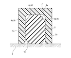
図7は図6に示した圧縮変形状態でのガスケット1の内部応力分布を示していて、同図の複数段階の濃淡のうち淡い部分ほど内部応力が高いことを表している。この図7からも明らかなように、ガスケット本体部5の中心部よりも双方の端面突起部6a,6bの内部応力が高く、特に他方の部材3側の端面突起部6bの面圧が高いことが容易に理解できる。
FIG. 7 shows the internal stress distribution of the
このように本実施の形態では、二部材2,3同士の突き合わせによりガスケット溝4内でガスケット1が圧縮変形(弾性変形)した場合に、ガスケット本体部5の中央部での幅方向への変形を規制しつつ、両端の端面突起部6a,6bを積極的に圧縮変形させることができる。これにより、機能上必要な面圧を十分に確保することができ、ガスケット1の断面形状を縮小化しても所期の機能を安定して維持することができことになる。
As described above, in the present embodiment, when the
上記実施の形態のガスケット1と従来の同等品との性能比較を行うべく本発明者が実験を行ったところ、本実施の形態では、ガスケット1の断面積として20%程度縮小化できたことが確認できた。また、本実施の形態では従来の同等品と比べ、初期面圧で約40%高めることができ、圧縮永久歪み率で約30%低減できることが確認できた。
When the present inventor conducted an experiment to compare the performance of the
さらに、図1,3に示したように、ガスケット1の長手方向または周長方向の四箇所に設定されて脱落防止手段として機能することになる小さな突起部10は、上記のような面圧低下抑制効果もしくは面圧維持効果を阻害することがないように、ガスケット1の長手方向または周長方向の全周ではなく、長手方向または周長方向において所期の目的を達成できる最低限の間隔で設定している。そして、仮に図4に示したガスケット溝4の溝幅W1が許容寸法公差内の最大公差を有し、且つ図2に示したガスケット本体部5の最大幅寸法Wが許容寸法公差内の最小公差を有している場合であっても、突起部10がガスケット溝4の内側面4bに圧接するようにその突出量を設定してある。したがって、図4に示したように、ガスケット1をガスケット溝4に挿入した圧縮変形前の自由状態であっても、各突起部10はガスケット溝4の内側面4bに圧接するかたちとなる。これにより、図4の状態でのガスケット溝4からのガスケット1の脱落を未然に防止することができることになる。
Further, as shown in FIGS. 1 and 3, the
なお、本実施の形態では、先に述べたように、ガスケット1をエンジンのシリンダヘッドとインテークマニホールドとの接合部に適用した場合を例にとって説明したが、適用部位はこれに限定されるものではない。例えば、エンジンに付帯することになるスロットルバルブやEGRパイプ等の接合部のガスケットとしても当然に用いることができる。また、ガスケット1の平面形状は楕円形または長円形をなす閉ループ状のものに限らず、適用部位の溝周形状に応じて例えば円形、四角形、八角形等であっても良い。
In the present embodiment, as described above, the case where the
さらに、ガスケット1自体の摩擦力等によりガスケット溝4からの脱落防止効果が発揮されて自己保持できる場合には、脱落防止用の一対の突起部10は必ずしも必須ではない。その上、脱落防止用の一対の突起部10を備える場合であっても、この脱落防止用の突起部10の位置、数および形状は上記実施の形態のものに限定されない。要は突起部10として脱落防止効果が発揮される形状であれば良いから、例えば突起部10の形状としては円形以外の任意に形状でも良く、必要に応じてガスケット1の周長全周に連続して形成することもまた可能である。
Further, when the
図8は本発明に係る密封構造の第2の実施の形態を示す図で、先の第1の実施の形態と共通する部分には同一符号を付してある。 FIG. 8 is a diagram showing a second embodiment of the sealing structure according to the present invention, and the same reference numerals are given to the portions common to the first embodiment.
この第2の実施の形態では、図1に示したガスケット1をガスケット素片11aとして用いて、三つのガスケット素片11aを各ガスケット素片11aの長径方向に延びるブリッジ部12を介して相互に接続するべく、各ガスケット素片11aとブリッジ部12とを一体に成形して、いわゆる3連式ガスケット11としたものである。
In the second embodiment, the
このような3連式ガスケット11は、図9に示すように、例えば3気筒タイプのエンジン13における例えばアルミニウム合金製のシリンダヘッドの吸気ポート14と樹脂製のインテークマニホールド15とを接続するにあたり、インテークマニホールド15側のフランジ部15aに形成された図示外のガスケット溝に予め装着されることになる。なお、図1に示した第1の実施の形態のガスケット1も3個を同時使用することで図9と同様の形態で使用できることは言うまでもない。
As shown in FIG. 9, such a
この第2の実施の形態では、ガスケット素片11aが3連式である点でのみ先の第1の実施の形態と相違しており、したがって、この第2の実施の形態においても第1の実施の形態と同様の効果が得られることになる。
The second embodiment is different from the first embodiment only in that the
1…ガスケット
2…一方の部材
3…他方の部材
4…ガスケット溝
4a…溝底面
4b…内側面
5…ガスケット本体部
5a…圧接面
6a,6b…端面突起部
7…先端面
10…突起部
DESCRIPTION OF
Claims (4)
前記ガスケット溝は溝底面の両側に位置する内側面が互いに平行に形成されている一方、
前記ガスケットは、その断面において、
幅方向での双方の外側面が前記ガスケット溝の内側面に対する圧接面となっているガスケット本体部と、
前記ガスケット本体部から幅方向と直交する高さ方向の両側にそれぞれに突出して当該ガスケット本体部よりも幅狭で且つ先細り形状をなしていて、一方が前記ガスケット溝の溝底面に、他方が前記他方の部材にそれぞれ圧接することになる端面突起部と、
とから形成されていて、
前記ガスケット本体部の圧接面が前記ガスケット溝の内側面に向かって凸形状となる円弧状面として形成されていることを特徴とする密封構造。 A gasket groove formed in one member and a gasket inserted into the gasket groove are provided, and the gasket is compressed and deformed by abutment between the one member and the other member, thereby sealing between the two members. A sealed structure
While the gasket groove is formed such that inner surfaces located on both sides of the groove bottom surface are parallel to each other,
The gasket, in its cross section,
A gasket body portion in which both outer surfaces in the width direction are pressure contact surfaces with respect to the inner surface of the gasket groove;
The gasket body part protrudes on both sides in the height direction perpendicular to the width direction and is narrower and tapered than the gasket body part, one on the groove bottom surface of the gasket groove and the other on the End surface protrusions that are in pressure contact with the other members,
And formed from
The sealing structure, wherein the pressure contact surface of the gasket main body is formed as an arcuate surface that is convex toward the inner surface of the gasket groove.
前記ガスケット本体部の幅寸法に対する前記端面突起部の先端面の曲率半径の割合が15%以下となっていることを特徴とする請求項2に記載の密封構造。 In the cross section of the gasket, the end surfaces of both end surface protrusions are arcuate surfaces,
The sealing structure according to claim 2, wherein a ratio of a curvature radius of a tip surface of the end surface protrusion to a width dimension of the gasket main body is 15% or less.
前記ガスケット本体部における圧接面の長手方向の一部に、一対の突起部が高さ方向で並んで形成されていることを特徴とする請求項3に記載の密封構造。 The gasket is formed so that the basic cross-sectional shape is uniform in the longitudinal direction,
The sealing structure according to claim 3, wherein a pair of protrusions are formed side by side in the height direction on a part of the pressure contact surface of the gasket main body in the longitudinal direction.
Priority Applications (4)
| Application Number | Priority Date | Filing Date | Title |
|---|---|---|---|
| JP2016238957A JP2018096400A (en) | 2016-12-09 | 2016-12-09 | Sealing structure |
| EP17205163.3A EP3333464B1 (en) | 2016-12-09 | 2017-12-04 | Sealing structure |
| CN201711274329.7A CN108223796A (en) | 2016-12-09 | 2017-12-06 | Seal construction |
| US15/835,897 US10731760B2 (en) | 2016-12-09 | 2017-12-08 | Sealing structure |
Applications Claiming Priority (1)
| Application Number | Priority Date | Filing Date | Title |
|---|---|---|---|
| JP2016238957A JP2018096400A (en) | 2016-12-09 | 2016-12-09 | Sealing structure |
Publications (1)
| Publication Number | Publication Date |
|---|---|
| JP2018096400A true JP2018096400A (en) | 2018-06-21 |
Family
ID=60569802
Family Applications (1)
| Application Number | Title | Priority Date | Filing Date |
|---|---|---|---|
| JP2016238957A Pending JP2018096400A (en) | 2016-12-09 | 2016-12-09 | Sealing structure |
Country Status (4)
| Country | Link |
|---|---|
| US (1) | US10731760B2 (en) |
| EP (1) | EP3333464B1 (en) |
| JP (1) | JP2018096400A (en) |
| CN (1) | CN108223796A (en) |
Cited By (5)
| Publication number | Priority date | Publication date | Assignee | Title |
|---|---|---|---|---|
| KR20200140658A (en) * | 2019-06-07 | 2020-12-16 | 평화오일씰공업주식회사 | Gasket for sealing |
| KR20200140660A (en) * | 2019-06-07 | 2020-12-16 | 평화오일씰공업주식회사 | Gasket for sealing |
| KR20210114633A (en) * | 2020-03-11 | 2021-09-24 | 평화오일씰공업주식회사 | Gasket for sealing |
| WO2023002985A1 (en) * | 2021-07-19 | 2023-01-26 | Nok株式会社 | Gasket |
| WO2023047896A1 (en) | 2021-09-27 | 2023-03-30 | Nok株式会社 | Gasket |
Families Citing this family (7)
| Publication number | Priority date | Publication date | Assignee | Title |
|---|---|---|---|---|
| USD836186S1 (en) * | 2016-07-05 | 2018-12-18 | Valqua, Ltd. | Seal member for a pressure vessel |
| JP2020143750A (en) * | 2019-03-07 | 2020-09-10 | 東洋電装株式会社 | Seal structure and switch device |
| CN210467924U (en) * | 2019-09-17 | 2020-05-05 | 宁德时代新能源科技股份有限公司 | Battery package and vehicle |
| KR20210114635A (en) * | 2020-03-11 | 2021-09-24 | 삼성전자주식회사 | Display apparatus |
| US20220099185A1 (en) * | 2020-09-25 | 2022-03-31 | Flowserve Management Company | Pressure retained gasket seal with enhanced unloading resistance |
| JP2024513614A (en) * | 2021-04-01 | 2024-03-27 | ジェイ.エス.ティー.コーポレーション | Elastomer seal spring |
| US11674596B2 (en) * | 2021-11-01 | 2023-06-13 | Kennedy Valve Company | Seal with first elastomeric element and second elastomeric element |
Citations (7)
| Publication number | Priority date | Publication date | Assignee | Title |
|---|---|---|---|---|
| JP2002195411A (en) * | 2001-11-15 | 2002-07-10 | Nok Corp | Gasket |
| JP2008281110A (en) * | 2007-05-10 | 2008-11-20 | Nok Corp | Sealing structure |
| CN101925765A (en) * | 2008-01-30 | 2010-12-22 | Nok株式会社 | Gasket |
| JP2013040673A (en) * | 2011-08-19 | 2013-02-28 | Nok Corp | Sealing structure |
| JP2013057379A (en) * | 2011-09-09 | 2013-03-28 | Uchiyama Manufacturing Corp | Gasket |
| JP2013079667A (en) * | 2011-10-03 | 2013-05-02 | Uchiyama Manufacturing Corp | Gasket |
| WO2016006393A1 (en) * | 2014-07-07 | 2016-01-14 | Nok株式会社 | Gasket |
Family Cites Families (12)
| Publication number | Priority date | Publication date | Assignee | Title |
|---|---|---|---|---|
| US6722660B2 (en) * | 2002-06-27 | 2004-04-20 | Federal-Mogul World Wide, Inc. | Molded gasket |
| JPWO2004007937A1 (en) * | 2002-07-12 | 2005-11-10 | 内山工業株式会社 | gasket |
| CN101091078A (en) * | 2005-04-22 | 2007-12-19 | Nok株式会社 | Gasket |
| US20080265523A1 (en) * | 2007-04-30 | 2008-10-30 | Freudenberg-Nok General Partnership | Asymmetric Gasket |
| US20100084827A1 (en) * | 2008-10-08 | 2010-04-08 | Peddle Darron G | Self-retaining seal for undercut groove |
| US20110227295A1 (en) * | 2008-11-25 | 2011-09-22 | Nok Corporation | Two-material composite gasket |
| US20110169228A1 (en) * | 2010-01-13 | 2011-07-14 | Gm Global Technology Operations, Inc. | Sealing gasket |
| JP5760411B2 (en) * | 2010-12-08 | 2015-08-12 | Nok株式会社 | gasket |
| FR2970312B1 (en) * | 2011-01-12 | 2013-10-11 | Freudenberg Carl Kg | SEMI-ONDULE JOINT |
| WO2013005722A1 (en) * | 2011-07-04 | 2013-01-10 | 株式会社ミクニ | Gasket and throttle body |
| JP6056343B2 (en) * | 2012-10-03 | 2017-01-11 | Nok株式会社 | Sealing structure |
| US10260632B2 (en) * | 2013-09-20 | 2019-04-16 | Micromass Uk Limited | Chamber seal for mass spectrometer |
-
2016
- 2016-12-09 JP JP2016238957A patent/JP2018096400A/en active Pending
-
2017
- 2017-12-04 EP EP17205163.3A patent/EP3333464B1/en active Active
- 2017-12-06 CN CN201711274329.7A patent/CN108223796A/en active Pending
- 2017-12-08 US US15/835,897 patent/US10731760B2/en active Active
Patent Citations (7)
| Publication number | Priority date | Publication date | Assignee | Title |
|---|---|---|---|---|
| JP2002195411A (en) * | 2001-11-15 | 2002-07-10 | Nok Corp | Gasket |
| JP2008281110A (en) * | 2007-05-10 | 2008-11-20 | Nok Corp | Sealing structure |
| CN101925765A (en) * | 2008-01-30 | 2010-12-22 | Nok株式会社 | Gasket |
| JP2013040673A (en) * | 2011-08-19 | 2013-02-28 | Nok Corp | Sealing structure |
| JP2013057379A (en) * | 2011-09-09 | 2013-03-28 | Uchiyama Manufacturing Corp | Gasket |
| JP2013079667A (en) * | 2011-10-03 | 2013-05-02 | Uchiyama Manufacturing Corp | Gasket |
| WO2016006393A1 (en) * | 2014-07-07 | 2016-01-14 | Nok株式会社 | Gasket |
Cited By (8)
| Publication number | Priority date | Publication date | Assignee | Title |
|---|---|---|---|---|
| KR20200140658A (en) * | 2019-06-07 | 2020-12-16 | 평화오일씰공업주식회사 | Gasket for sealing |
| KR20200140660A (en) * | 2019-06-07 | 2020-12-16 | 평화오일씰공업주식회사 | Gasket for sealing |
| KR102239332B1 (en) * | 2019-06-07 | 2021-04-21 | 평화오일씰공업 주식회사 | Gasket for sealing |
| KR102251418B1 (en) | 2019-06-07 | 2021-05-12 | 평화오일씰공업 주식회사 | Gasket for sealing |
| KR20210114633A (en) * | 2020-03-11 | 2021-09-24 | 평화오일씰공업주식회사 | Gasket for sealing |
| KR102372680B1 (en) * | 2020-03-11 | 2022-03-10 | 평화오일씰공업 주식회사 | Gasket for sealing |
| WO2023002985A1 (en) * | 2021-07-19 | 2023-01-26 | Nok株式会社 | Gasket |
| WO2023047896A1 (en) | 2021-09-27 | 2023-03-30 | Nok株式会社 | Gasket |
Also Published As
| Publication number | Publication date |
|---|---|
| US10731760B2 (en) | 2020-08-04 |
| EP3333464A1 (en) | 2018-06-13 |
| EP3333464B1 (en) | 2022-10-19 |
| CN108223796A (en) | 2018-06-29 |
| US20180163868A1 (en) | 2018-06-14 |
Similar Documents
| Publication | Publication Date | Title |
|---|---|---|
| JP2018096400A (en) | Sealing structure | |
| JP3349132B2 (en) | Low load seal | |
| US10415665B2 (en) | Fluid-filled vibration-damping device | |
| KR101436761B1 (en) | Tank rubber cushion | |
| JP4824351B2 (en) | gasket | |
| EP1640643A1 (en) | Gasket | |
| TW200535355A (en) | Molded plastic gasket | |
| JPWO2010128606A1 (en) | Waterproof structure of the opening / closing part of the equipment case | |
| JP6532242B2 (en) | Sealing material | |
| JP2010138957A (en) | Gasket | |
| JP2008185072A (en) | Coil spring | |
| JP2007107546A (en) | Gasket | |
| JP2008298246A (en) | Seal ring for plane | |
| JP2006029364A (en) | Gasket | |
| JP5450575B2 (en) | Gasket with beads | |
| JP5434681B2 (en) | Gasket and sealing structure | |
| JP5988248B2 (en) | Sealing structure of three-sided joint | |
| JP4716828B2 (en) | Metal seal | |
| JP6257277B2 (en) | Metal seal | |
| JP6855506B2 (en) | Metal gasket | |
| JP7370779B2 (en) | Sealed structure | |
| JP2009024712A (en) | Sealing device | |
| JP2005054827A (en) | Sealing device | |
| JP5827637B2 (en) | Coil spring | |
| JP7181579B2 (en) | gasket |
Legal Events
| Date | Code | Title | Description |
|---|---|---|---|
| A621 | Written request for application examination |
Free format text: JAPANESE INTERMEDIATE CODE: A621 Effective date: 20191127 |
|
| A131 | Notification of reasons for refusal |
Free format text: JAPANESE INTERMEDIATE CODE: A131 Effective date: 20201027 |
|
| A521 | Request for written amendment filed |
Free format text: JAPANESE INTERMEDIATE CODE: A523 Effective date: 20201117 |
|
| A02 | Decision of refusal |
Free format text: JAPANESE INTERMEDIATE CODE: A02 Effective date: 20210112 |