JP2018094902A - Liquid composition for surface treatment of printed matter, ink set, recording method and recording device - Google Patents
Liquid composition for surface treatment of printed matter, ink set, recording method and recording device Download PDFInfo
- Publication number
- JP2018094902A JP2018094902A JP2017031904A JP2017031904A JP2018094902A JP 2018094902 A JP2018094902 A JP 2018094902A JP 2017031904 A JP2017031904 A JP 2017031904A JP 2017031904 A JP2017031904 A JP 2017031904A JP 2018094902 A JP2018094902 A JP 2018094902A
- Authority
- JP
- Japan
- Prior art keywords
- ink
- liquid composition
- surface treatment
- resin particles
- white
- Prior art date
- Legal status (The legal status is an assumption and is not a legal conclusion. Google has not performed a legal analysis and makes no representation as to the accuracy of the status listed.)
- Granted
Links
- 239000007788 liquid Substances 0.000 title claims abstract description 328
- 239000000203 mixture Substances 0.000 title claims abstract description 125
- 238000004381 surface treatment Methods 0.000 title claims abstract description 51
- 238000000034 method Methods 0.000 title claims description 58
- 239000002245 particle Substances 0.000 claims abstract description 130
- 229920005989 resin Polymers 0.000 claims abstract description 114
- 239000011347 resin Substances 0.000 claims abstract description 114
- 229910052751 metal Inorganic materials 0.000 claims abstract description 28
- 239000002184 metal Substances 0.000 claims abstract description 28
- 150000003839 salts Chemical class 0.000 claims abstract description 26
- 239000000463 material Substances 0.000 claims description 72
- 238000007639 printing Methods 0.000 claims description 54
- 239000000758 substrate Substances 0.000 claims description 21
- 229920005992 thermoplastic resin Polymers 0.000 claims description 17
- 230000009477 glass transition Effects 0.000 claims description 13
- 229920002803 thermoplastic polyurethane Polymers 0.000 claims description 13
- 230000004048 modification Effects 0.000 claims description 10
- 238000012986 modification Methods 0.000 claims description 10
- AZDRQVAHHNSJOQ-UHFFFAOYSA-N alumane Chemical class [AlH3] AZDRQVAHHNSJOQ-UHFFFAOYSA-N 0.000 claims description 9
- 230000008569 process Effects 0.000 claims description 9
- 238000007599 discharging Methods 0.000 claims description 8
- MTAZNLWOLGHBHU-UHFFFAOYSA-N butadiene-styrene rubber Chemical compound C=CC=C.C=CC1=CC=CC=C1 MTAZNLWOLGHBHU-UHFFFAOYSA-N 0.000 claims description 6
- 229920003048 styrene butadiene rubber Polymers 0.000 claims description 6
- 239000002174 Styrene-butadiene Substances 0.000 claims description 5
- 159000000007 calcium salts Chemical class 0.000 claims description 5
- 229920001577 copolymer Polymers 0.000 claims description 5
- 229920005672 polyolefin resin Polymers 0.000 claims description 5
- 239000011115 styrene butadiene Substances 0.000 claims description 5
- DIZPMCHEQGEION-UHFFFAOYSA-H aluminium sulfate (anhydrous) Chemical compound [Al+3].[Al+3].[O-]S([O-])(=O)=O.[O-]S([O-])(=O)=O.[O-]S([O-])(=O)=O DIZPMCHEQGEION-UHFFFAOYSA-H 0.000 claims description 4
- 159000000003 magnesium salts Chemical class 0.000 claims description 4
- 150000002815 nickel Chemical class 0.000 claims description 4
- 239000011118 polyvinyl acetate Substances 0.000 claims description 4
- 229920002689 polyvinyl acetate Polymers 0.000 claims description 4
- 239000004800 polyvinyl chloride Substances 0.000 claims description 4
- 229920000915 polyvinyl chloride Polymers 0.000 claims description 4
- VEXZGXHMUGYJMC-UHFFFAOYSA-M Chloride anion Chemical compound [Cl-] VEXZGXHMUGYJMC-UHFFFAOYSA-M 0.000 claims description 3
- ILRRQNADMUWWFW-UHFFFAOYSA-K aluminium phosphate Chemical compound O1[Al]2OP1(=O)O2 ILRRQNADMUWWFW-UHFFFAOYSA-K 0.000 claims description 3
- GRLPQNLYRHEGIJ-UHFFFAOYSA-J potassium aluminium sulfate Chemical compound [Al+3].[K+].[O-]S([O-])(=O)=O.[O-]S([O-])(=O)=O GRLPQNLYRHEGIJ-UHFFFAOYSA-J 0.000 claims description 3
- 238000003860 storage Methods 0.000 abstract description 18
- 239000000976 ink Substances 0.000 description 421
- 239000000049 pigment Substances 0.000 description 86
- 238000011156 evaluation Methods 0.000 description 85
- 239000006185 dispersion Substances 0.000 description 60
- -1 aluminum ions Chemical class 0.000 description 44
- 238000002360 preparation method Methods 0.000 description 44
- 208000028659 discharge Diseases 0.000 description 32
- 239000010408 film Substances 0.000 description 32
- BBEAQIROQSPTKN-UHFFFAOYSA-N pyrene Chemical compound C1=CC=C2C=CC3=CC=CC4=CC=C1C2=C43 BBEAQIROQSPTKN-UHFFFAOYSA-N 0.000 description 26
- 238000001035 drying Methods 0.000 description 25
- 239000007787 solid Substances 0.000 description 22
- 239000000839 emulsion Substances 0.000 description 21
- 238000000576 coating method Methods 0.000 description 19
- 239000002609 medium Substances 0.000 description 19
- 238000010438 heat treatment Methods 0.000 description 16
- XLYOFNOQVPJJNP-UHFFFAOYSA-N water Substances O XLYOFNOQVPJJNP-UHFFFAOYSA-N 0.000 description 16
- 229920006378 biaxially oriented polypropylene Polymers 0.000 description 13
- 239000011127 biaxially oriented polypropylene Substances 0.000 description 13
- GVEPBJHOBDJJJI-UHFFFAOYSA-N fluoranthrene Natural products C1=CC(C2=CC=CC=C22)=C3C2=CC=CC3=C1 GVEPBJHOBDJJJI-UHFFFAOYSA-N 0.000 description 13
- 239000012530 fluid Substances 0.000 description 12
- 239000004094 surface-active agent Substances 0.000 description 12
- RTZKZFJDLAIYFH-UHFFFAOYSA-N Diethyl ether Chemical compound CCOCC RTZKZFJDLAIYFH-UHFFFAOYSA-N 0.000 description 11
- 230000008859 change Effects 0.000 description 11
- 239000011248 coating agent Substances 0.000 description 11
- 239000003960 organic solvent Substances 0.000 description 11
- 239000000126 substance Substances 0.000 description 11
- 239000012463 white pigment Substances 0.000 description 11
- 239000004925 Acrylic resin Substances 0.000 description 10
- 229920000178 Acrylic resin Polymers 0.000 description 10
- 239000006229 carbon black Substances 0.000 description 10
- 239000002270 dispersing agent Substances 0.000 description 10
- 239000010410 layer Substances 0.000 description 10
- 238000003756 stirring Methods 0.000 description 10
- LYCAIKOWRPUZTN-UHFFFAOYSA-N Ethylene glycol Chemical compound OCCO LYCAIKOWRPUZTN-UHFFFAOYSA-N 0.000 description 9
- 238000004062 sedimentation Methods 0.000 description 9
- 238000004804 winding Methods 0.000 description 9
- XEEYBQQBJWHFJM-UHFFFAOYSA-N Iron Chemical compound [Fe] XEEYBQQBJWHFJM-UHFFFAOYSA-N 0.000 description 8
- 239000003086 colorant Substances 0.000 description 8
- 238000004040 coloring Methods 0.000 description 8
- 238000002156 mixing Methods 0.000 description 8
- 229910052782 aluminium Inorganic materials 0.000 description 7
- 239000003795 chemical substances by application Substances 0.000 description 7
- 230000000052 comparative effect Effects 0.000 description 7
- 150000001875 compounds Chemical class 0.000 description 7
- 230000000694 effects Effects 0.000 description 7
- 239000005038 ethylene vinyl acetate Substances 0.000 description 7
- IJGRMHOSHXDMSA-UHFFFAOYSA-N nitrogen Substances N#N IJGRMHOSHXDMSA-UHFFFAOYSA-N 0.000 description 7
- 229920001200 poly(ethylene-vinyl acetate) Polymers 0.000 description 7
- 229920001225 polyester resin Polymers 0.000 description 7
- 239000004645 polyester resin Substances 0.000 description 7
- 229920001296 polysiloxane Polymers 0.000 description 7
- 229920005792 styrene-acrylic resin Polymers 0.000 description 7
- 238000012546 transfer Methods 0.000 description 7
- OKTJSMMVPCPJKN-UHFFFAOYSA-N Carbon Chemical compound [C] OKTJSMMVPCPJKN-UHFFFAOYSA-N 0.000 description 6
- 229920003171 Poly (ethylene oxide) Polymers 0.000 description 6
- VYPSYNLAJGMNEJ-UHFFFAOYSA-N Silicium dioxide Chemical compound O=[Si]=O VYPSYNLAJGMNEJ-UHFFFAOYSA-N 0.000 description 6
- PPBRXRYQALVLMV-UHFFFAOYSA-N Styrene Chemical compound C=CC1=CC=CC=C1 PPBRXRYQALVLMV-UHFFFAOYSA-N 0.000 description 6
- YXFVVABEGXRONW-UHFFFAOYSA-N Toluene Chemical compound CC1=CC=CC=C1 YXFVVABEGXRONW-UHFFFAOYSA-N 0.000 description 6
- XAGFODPZIPBFFR-UHFFFAOYSA-N aluminium Chemical compound [Al] XAGFODPZIPBFFR-UHFFFAOYSA-N 0.000 description 6
- 238000006243 chemical reaction Methods 0.000 description 6
- 239000000243 solution Substances 0.000 description 6
- 150000005846 sugar alcohols Polymers 0.000 description 6
- 238000003851 corona treatment Methods 0.000 description 5
- 125000000524 functional group Chemical group 0.000 description 5
- 238000010030 laminating Methods 0.000 description 5
- 239000002736 nonionic surfactant Substances 0.000 description 5
- 229920000642 polymer Polymers 0.000 description 5
- 239000001052 yellow pigment Substances 0.000 description 5
- VGGSQFUCUMXWEO-UHFFFAOYSA-N Ethene Chemical compound C=C VGGSQFUCUMXWEO-UHFFFAOYSA-N 0.000 description 4
- 239000005977 Ethylene Substances 0.000 description 4
- MHAJPDPJQMAIIY-UHFFFAOYSA-N Hydrogen peroxide Chemical compound OO MHAJPDPJQMAIIY-UHFFFAOYSA-N 0.000 description 4
- UQSXHKLRYXJYBZ-UHFFFAOYSA-N Iron oxide Chemical compound [Fe]=O UQSXHKLRYXJYBZ-UHFFFAOYSA-N 0.000 description 4
- SECXISVLQFMRJM-UHFFFAOYSA-N N-Methylpyrrolidone Chemical compound CN1CCCC1=O SECXISVLQFMRJM-UHFFFAOYSA-N 0.000 description 4
- PXHVJJICTQNCMI-UHFFFAOYSA-N Nickel Chemical compound [Ni] PXHVJJICTQNCMI-UHFFFAOYSA-N 0.000 description 4
- 239000004743 Polypropylene Substances 0.000 description 4
- GWEVSGVZZGPLCZ-UHFFFAOYSA-N Titan oxide Chemical compound O=[Ti]=O GWEVSGVZZGPLCZ-UHFFFAOYSA-N 0.000 description 4
- RTAQQCXQSZGOHL-UHFFFAOYSA-N Titanium Chemical compound [Ti] RTAQQCXQSZGOHL-UHFFFAOYSA-N 0.000 description 4
- XTXRWKRVRITETP-UHFFFAOYSA-N Vinyl acetate Chemical compound CC(=O)OC=C XTXRWKRVRITETP-UHFFFAOYSA-N 0.000 description 4
- NIXOWILDQLNWCW-UHFFFAOYSA-N acrylic acid group Chemical group C(C=C)(=O)O NIXOWILDQLNWCW-UHFFFAOYSA-N 0.000 description 4
- 239000002518 antifoaming agent Substances 0.000 description 4
- TZCXTZWJZNENPQ-UHFFFAOYSA-L barium sulfate Chemical compound [Ba+2].[O-]S([O-])(=O)=O TZCXTZWJZNENPQ-UHFFFAOYSA-L 0.000 description 4
- DQXBYHZEEUGOBF-UHFFFAOYSA-N but-3-enoic acid;ethene Chemical compound C=C.OC(=O)CC=C DQXBYHZEEUGOBF-UHFFFAOYSA-N 0.000 description 4
- 239000011575 calcium Substances 0.000 description 4
- XQKKWWCELHKGKB-UHFFFAOYSA-L calcium acetate monohydrate Chemical compound O.[Ca+2].CC([O-])=O.CC([O-])=O XQKKWWCELHKGKB-UHFFFAOYSA-L 0.000 description 4
- 229910052799 carbon Inorganic materials 0.000 description 4
- 150000001768 cations Chemical class 0.000 description 4
- 230000007423 decrease Effects 0.000 description 4
- 238000000151 deposition Methods 0.000 description 4
- 238000010586 diagram Methods 0.000 description 4
- 239000004205 dimethyl polysiloxane Substances 0.000 description 4
- 239000000975 dye Substances 0.000 description 4
- 125000001033 ether group Chemical group 0.000 description 4
- 229910052742 iron Inorganic materials 0.000 description 4
- 230000000670 limiting effect Effects 0.000 description 4
- 230000007774 longterm Effects 0.000 description 4
- 229910052757 nitrogen Inorganic materials 0.000 description 4
- 125000005010 perfluoroalkyl group Chemical group 0.000 description 4
- 229920000435 poly(dimethylsiloxane) Polymers 0.000 description 4
- 229920000139 polyethylene terephthalate Polymers 0.000 description 4
- 239000005020 polyethylene terephthalate Substances 0.000 description 4
- 238000006116 polymerization reaction Methods 0.000 description 4
- 229920001155 polypropylene Polymers 0.000 description 4
- 229910052719 titanium Inorganic materials 0.000 description 4
- 239000010936 titanium Substances 0.000 description 4
- OGIDPMRJRNCKJF-UHFFFAOYSA-N titanium oxide Inorganic materials [Ti]=O OGIDPMRJRNCKJF-UHFFFAOYSA-N 0.000 description 4
- DNIAPMSPPWPWGF-GSVOUGTGSA-N (R)-(-)-Propylene glycol Chemical compound C[C@@H](O)CO DNIAPMSPPWPWGF-GSVOUGTGSA-N 0.000 description 3
- OYPRJOBELJOOCE-UHFFFAOYSA-N Calcium Chemical compound [Ca] OYPRJOBELJOOCE-UHFFFAOYSA-N 0.000 description 3
- RYGMFSIKBFXOCR-UHFFFAOYSA-N Copper Chemical compound [Cu] RYGMFSIKBFXOCR-UHFFFAOYSA-N 0.000 description 3
- ZMXDDKWLCZADIW-UHFFFAOYSA-N N,N-Dimethylformamide Chemical compound CN(C)C=O ZMXDDKWLCZADIW-UHFFFAOYSA-N 0.000 description 3
- HEMHJVSKTPXQMS-UHFFFAOYSA-M Sodium hydroxide Chemical compound [OH-].[Na+] HEMHJVSKTPXQMS-UHFFFAOYSA-M 0.000 description 3
- ZMANZCXQSJIPKH-UHFFFAOYSA-N Triethylamine Chemical compound CCN(CC)CC ZMANZCXQSJIPKH-UHFFFAOYSA-N 0.000 description 3
- 239000002253 acid Substances 0.000 description 3
- 239000000654 additive Substances 0.000 description 3
- 239000000853 adhesive Substances 0.000 description 3
- 230000001070 adhesive effect Effects 0.000 description 3
- 238000004220 aggregation Methods 0.000 description 3
- 230000002776 aggregation Effects 0.000 description 3
- 239000000956 alloy Substances 0.000 description 3
- 229910045601 alloy Inorganic materials 0.000 description 3
- 239000002280 amphoteric surfactant Substances 0.000 description 3
- 239000003945 anionic surfactant Substances 0.000 description 3
- 230000002421 anti-septic effect Effects 0.000 description 3
- 239000003429 antifungal agent Substances 0.000 description 3
- 229940121375 antifungal agent Drugs 0.000 description 3
- 239000004599 antimicrobial Substances 0.000 description 3
- 239000007864 aqueous solution Substances 0.000 description 3
- 229910052791 calcium Inorganic materials 0.000 description 3
- 239000001639 calcium acetate Substances 0.000 description 3
- 229960005147 calcium acetate Drugs 0.000 description 3
- 235000011092 calcium acetate Nutrition 0.000 description 3
- 229920006026 co-polymeric resin Polymers 0.000 description 3
- 238000001816 cooling Methods 0.000 description 3
- 229910052802 copper Inorganic materials 0.000 description 3
- 239000010949 copper Substances 0.000 description 3
- XCJYREBRNVKWGJ-UHFFFAOYSA-N copper(II) phthalocyanine Chemical compound [Cu+2].C12=CC=CC=C2C(N=C2[N-]C(C3=CC=CC=C32)=N2)=NC1=NC([C]1C=CC=CC1=1)=NC=1N=C1[C]3C=CC=CC3=C2[N-]1 XCJYREBRNVKWGJ-UHFFFAOYSA-N 0.000 description 3
- 230000008021 deposition Effects 0.000 description 3
- 235000014113 dietary fatty acids Nutrition 0.000 description 3
- MTHSVFCYNBDYFN-UHFFFAOYSA-N diethylene glycol Chemical compound OCCOCCO MTHSVFCYNBDYFN-UHFFFAOYSA-N 0.000 description 3
- 239000003995 emulsifying agent Substances 0.000 description 3
- 239000000194 fatty acid Substances 0.000 description 3
- 229930195729 fatty acid Natural products 0.000 description 3
- 235000013305 food Nutrition 0.000 description 3
- 238000009472 formulation Methods 0.000 description 3
- 238000005304 joining Methods 0.000 description 3
- 238000003475 lamination Methods 0.000 description 3
- 238000005259 measurement Methods 0.000 description 3
- 230000007246 mechanism Effects 0.000 description 3
- 239000012528 membrane Substances 0.000 description 3
- 229910044991 metal oxide Inorganic materials 0.000 description 3
- 150000004706 metal oxides Chemical class 0.000 description 3
- DNIAPMSPPWPWGF-UHFFFAOYSA-N monopropylene glycol Natural products CC(O)CO DNIAPMSPPWPWGF-UHFFFAOYSA-N 0.000 description 3
- 239000012860 organic pigment Substances 0.000 description 3
- 238000009832 plasma treatment Methods 0.000 description 3
- 239000002985 plastic film Substances 0.000 description 3
- 229920006255 plastic film Polymers 0.000 description 3
- 235000013772 propylene glycol Nutrition 0.000 description 3
- 238000011084 recovery Methods 0.000 description 3
- 230000002829 reductive effect Effects 0.000 description 3
- 229910052710 silicon Inorganic materials 0.000 description 3
- 239000010703 silicon Substances 0.000 description 3
- 239000000377 silicon dioxide Substances 0.000 description 3
- 239000011734 sodium Substances 0.000 description 3
- PUPZLCDOIYMWBV-UHFFFAOYSA-N (+/-)-1,3-Butanediol Chemical compound CC(O)CCO PUPZLCDOIYMWBV-UHFFFAOYSA-N 0.000 description 2
- UNVGBIALRHLALK-UHFFFAOYSA-N 1,5-Hexanediol Chemical compound CC(O)CCCCO UNVGBIALRHLALK-UHFFFAOYSA-N 0.000 description 2
- FWLHAQYOFMQTHQ-UHFFFAOYSA-N 2-N-[8-[[8-(4-aminoanilino)-10-phenylphenazin-10-ium-2-yl]amino]-10-phenylphenazin-10-ium-2-yl]-8-N,10-diphenylphenazin-10-ium-2,8-diamine hydroxy-oxido-dioxochromium Chemical compound O[Cr]([O-])(=O)=O.O[Cr]([O-])(=O)=O.O[Cr]([O-])(=O)=O.Nc1ccc(Nc2ccc3nc4ccc(Nc5ccc6nc7ccc(Nc8ccc9nc%10ccc(Nc%11ccccc%11)cc%10[n+](-c%10ccccc%10)c9c8)cc7[n+](-c7ccccc7)c6c5)cc4[n+](-c4ccccc4)c3c2)cc1 FWLHAQYOFMQTHQ-UHFFFAOYSA-N 0.000 description 2
- YEJRWHAVMIAJKC-UHFFFAOYSA-N 4-Butyrolactone Chemical compound O=C1CCCO1 YEJRWHAVMIAJKC-UHFFFAOYSA-N 0.000 description 2
- VTYYLEPIZMXCLO-UHFFFAOYSA-L Calcium carbonate Chemical compound [Ca+2].[O-]C([O-])=O VTYYLEPIZMXCLO-UHFFFAOYSA-L 0.000 description 2
- VYZAMTAEIAYCRO-UHFFFAOYSA-N Chromium Chemical compound [Cr] VYZAMTAEIAYCRO-UHFFFAOYSA-N 0.000 description 2
- IAZDPXIOMUYVGZ-UHFFFAOYSA-N Dimethylsulphoxide Chemical compound CS(C)=O IAZDPXIOMUYVGZ-UHFFFAOYSA-N 0.000 description 2
- WSFSSNUMVMOOMR-UHFFFAOYSA-N Formaldehyde Chemical compound O=C WSFSSNUMVMOOMR-UHFFFAOYSA-N 0.000 description 2
- ZHNUHDYFZUAESO-UHFFFAOYSA-N Formamide Chemical compound NC=O ZHNUHDYFZUAESO-UHFFFAOYSA-N 0.000 description 2
- PEDCQBHIVMGVHV-UHFFFAOYSA-N Glycerine Chemical compound OCC(O)CO PEDCQBHIVMGVHV-UHFFFAOYSA-N 0.000 description 2
- FYYHWMGAXLPEAU-UHFFFAOYSA-N Magnesium Chemical compound [Mg] FYYHWMGAXLPEAU-UHFFFAOYSA-N 0.000 description 2
- TWRXJAOTZQYOKJ-UHFFFAOYSA-L Magnesium chloride Chemical compound [Mg+2].[Cl-].[Cl-] TWRXJAOTZQYOKJ-UHFFFAOYSA-L 0.000 description 2
- CSNNHWWHGAXBCP-UHFFFAOYSA-L Magnesium sulfate Chemical compound [Mg+2].[O-][S+2]([O-])([O-])[O-] CSNNHWWHGAXBCP-UHFFFAOYSA-L 0.000 description 2
- ATHHXGZTWNVVOU-UHFFFAOYSA-N N-methylformamide Chemical compound CNC=O ATHHXGZTWNVVOU-UHFFFAOYSA-N 0.000 description 2
- 239000002202 Polyethylene glycol Substances 0.000 description 2
- NRCMAYZCPIVABH-UHFFFAOYSA-N Quinacridone Chemical compound N1C2=CC=CC=C2C(=O)C2=C1C=C1C(=O)C3=CC=CC=C3NC1=C2 NRCMAYZCPIVABH-UHFFFAOYSA-N 0.000 description 2
- XUIMIQQOPSSXEZ-UHFFFAOYSA-N Silicon Chemical compound [Si] XUIMIQQOPSSXEZ-UHFFFAOYSA-N 0.000 description 2
- NINIDFKCEFEMDL-UHFFFAOYSA-N Sulfur Chemical compound [S] NINIDFKCEFEMDL-UHFFFAOYSA-N 0.000 description 2
- BZHJMEDXRYGGRV-UHFFFAOYSA-N Vinyl chloride Chemical compound ClC=C BZHJMEDXRYGGRV-UHFFFAOYSA-N 0.000 description 2
- MCMNRKCIXSYSNV-UHFFFAOYSA-N Zirconium dioxide Chemical compound O=[Zr]=O MCMNRKCIXSYSNV-UHFFFAOYSA-N 0.000 description 2
- 230000002378 acidificating effect Effects 0.000 description 2
- 150000005215 alkyl ethers Chemical class 0.000 description 2
- WNROFYMDJYEPJX-UHFFFAOYSA-K aluminium hydroxide Chemical compound [OH-].[OH-].[OH-].[Al+3] WNROFYMDJYEPJX-UHFFFAOYSA-K 0.000 description 2
- 150000001408 amides Chemical class 0.000 description 2
- 150000001412 amines Chemical class 0.000 description 2
- 125000000129 anionic group Chemical group 0.000 description 2
- 150000001450 anions Chemical class 0.000 description 2
- 239000012736 aqueous medium Substances 0.000 description 2
- 150000008378 aryl ethers Chemical class 0.000 description 2
- 238000007611 bar coating method Methods 0.000 description 2
- 229910052788 barium Inorganic materials 0.000 description 2
- DSAJWYNOEDNPEQ-UHFFFAOYSA-N barium atom Chemical compound [Ba] DSAJWYNOEDNPEQ-UHFFFAOYSA-N 0.000 description 2
- 239000011324 bead Substances 0.000 description 2
- DMSMPAJRVJJAGA-UHFFFAOYSA-N benzo[d]isothiazol-3-one Chemical compound C1=CC=C2C(=O)NSC2=C1 DMSMPAJRVJJAGA-UHFFFAOYSA-N 0.000 description 2
- BMRWNKZVCUKKSR-UHFFFAOYSA-N butane-1,2-diol Chemical compound CCC(O)CO BMRWNKZVCUKKSR-UHFFFAOYSA-N 0.000 description 2
- OWBTYPJTUOEWEK-UHFFFAOYSA-N butane-2,3-diol Chemical compound CC(O)C(C)O OWBTYPJTUOEWEK-UHFFFAOYSA-N 0.000 description 2
- 229910052793 cadmium Inorganic materials 0.000 description 2
- BDOSMKKIYDKNTQ-UHFFFAOYSA-N cadmium atom Chemical compound [Cd] BDOSMKKIYDKNTQ-UHFFFAOYSA-N 0.000 description 2
- ZCCIPPOKBCJFDN-UHFFFAOYSA-N calcium nitrate Chemical compound [Ca+2].[O-][N+]([O-])=O.[O-][N+]([O-])=O ZCCIPPOKBCJFDN-UHFFFAOYSA-N 0.000 description 2
- OSGAYBCDTDRGGQ-UHFFFAOYSA-L calcium sulfate Chemical compound [Ca+2].[O-]S([O-])(=O)=O OSGAYBCDTDRGGQ-UHFFFAOYSA-L 0.000 description 2
- 125000003178 carboxy group Chemical group [H]OC(*)=O 0.000 description 2
- 125000002091 cationic group Chemical group 0.000 description 2
- 229910052804 chromium Inorganic materials 0.000 description 2
- 239000011651 chromium Substances 0.000 description 2
- 238000004140 cleaning Methods 0.000 description 2
- 238000009820 dry lamination Methods 0.000 description 2
- JBKVHLHDHHXQEQ-UHFFFAOYSA-N epsilon-caprolactam Chemical compound O=C1CCCCCN1 JBKVHLHDHHXQEQ-UHFFFAOYSA-N 0.000 description 2
- 238000001914 filtration Methods 0.000 description 2
- 239000011521 glass Substances 0.000 description 2
- 238000007756 gravure coating Methods 0.000 description 2
- XXMIOPMDWAUFGU-UHFFFAOYSA-N hexane-1,6-diol Chemical compound OCCCCCCO XXMIOPMDWAUFGU-UHFFFAOYSA-N 0.000 description 2
- 238000002347 injection Methods 0.000 description 2
- 239000007924 injection Substances 0.000 description 2
- 239000001023 inorganic pigment Substances 0.000 description 2
- 150000002500 ions Chemical class 0.000 description 2
- JEIPFZHSYJVQDO-UHFFFAOYSA-N iron(III) oxide Inorganic materials O=[Fe]O[Fe]=O JEIPFZHSYJVQDO-UHFFFAOYSA-N 0.000 description 2
- 239000005001 laminate film Substances 0.000 description 2
- 229910052749 magnesium Inorganic materials 0.000 description 2
- 239000011777 magnesium Substances 0.000 description 2
- 238000004519 manufacturing process Methods 0.000 description 2
- 230000005499 meniscus Effects 0.000 description 2
- 150000002739 metals Chemical class 0.000 description 2
- 229910052759 nickel Inorganic materials 0.000 description 2
- 150000004767 nitrides Chemical class 0.000 description 2
- 229920006284 nylon film Polymers 0.000 description 2
- 230000003647 oxidation Effects 0.000 description 2
- 238000007254 oxidation reaction Methods 0.000 description 2
- 239000005022 packaging material Substances 0.000 description 2
- 238000004806 packaging method and process Methods 0.000 description 2
- BASFCYQUMIYNBI-UHFFFAOYSA-N platinum Chemical compound [Pt] BASFCYQUMIYNBI-UHFFFAOYSA-N 0.000 description 2
- 229920000767 polyaniline Polymers 0.000 description 2
- 229920000728 polyester Polymers 0.000 description 2
- 229920001223 polyethylene glycol Polymers 0.000 description 2
- 229920005749 polyurethane resin Polymers 0.000 description 2
- 238000007781 pre-processing Methods 0.000 description 2
- 230000003449 preventive effect Effects 0.000 description 2
- 238000003672 processing method Methods 0.000 description 2
- 239000000047 product Substances 0.000 description 2
- 238000010298 pulverizing process Methods 0.000 description 2
- HNJBEVLQSNELDL-UHFFFAOYSA-N pyrrolidin-2-one Chemical compound O=C1CCCN1 HNJBEVLQSNELDL-UHFFFAOYSA-N 0.000 description 2
- 229920002050 silicone resin Polymers 0.000 description 2
- 229910052708 sodium Inorganic materials 0.000 description 2
- 238000005507 spraying Methods 0.000 description 2
- 229910052712 strontium Inorganic materials 0.000 description 2
- CIOAGBVUUVVLOB-UHFFFAOYSA-N strontium atom Chemical compound [Sr] CIOAGBVUUVVLOB-UHFFFAOYSA-N 0.000 description 2
- 239000011593 sulfur Substances 0.000 description 2
- 229910052717 sulfur Inorganic materials 0.000 description 2
- 238000012360 testing method Methods 0.000 description 2
- 239000010409 thin film Substances 0.000 description 2
- 238000000108 ultra-filtration Methods 0.000 description 2
- 238000001132 ultrasonic dispersion Methods 0.000 description 2
- 238000011144 upstream manufacturing Methods 0.000 description 2
- 239000002699 waste material Substances 0.000 description 2
- DNIAPMSPPWPWGF-VKHMYHEASA-N (+)-propylene glycol Chemical compound C[C@H](O)CO DNIAPMSPPWPWGF-VKHMYHEASA-N 0.000 description 1
- YAXKTBLXMTYWDQ-UHFFFAOYSA-N 1,2,3-butanetriol Chemical compound CC(O)C(O)CO YAXKTBLXMTYWDQ-UHFFFAOYSA-N 0.000 description 1
- ZWVMLYRJXORSEP-UHFFFAOYSA-N 1,2,6-Hexanetriol Chemical compound OCCCCC(O)CO ZWVMLYRJXORSEP-UHFFFAOYSA-N 0.000 description 1
- 229940015975 1,2-hexanediol Drugs 0.000 description 1
- CYSGHNMQYZDMIA-UHFFFAOYSA-N 1,3-Dimethyl-2-imidazolidinon Chemical compound CN1CCN(C)C1=O CYSGHNMQYZDMIA-UHFFFAOYSA-N 0.000 description 1
- YPFDHNVEDLHUCE-UHFFFAOYSA-N 1,3-propanediol Substances OCCCO YPFDHNVEDLHUCE-UHFFFAOYSA-N 0.000 description 1
- 229940008841 1,6-hexamethylene diisocyanate Drugs 0.000 description 1
- JOLQKTGDSGKSKJ-UHFFFAOYSA-N 1-ethoxypropan-2-ol Chemical compound CCOCC(C)O JOLQKTGDSGKSKJ-UHFFFAOYSA-N 0.000 description 1
- JCTXKRPTIMZBJT-UHFFFAOYSA-N 2,2,4-trimethylpentane-1,3-diol Chemical compound CC(C)C(O)C(C)(C)CO JCTXKRPTIMZBJT-UHFFFAOYSA-N 0.000 description 1
- SBASXUCJHJRPEV-UHFFFAOYSA-N 2-(2-methoxyethoxy)ethanol Chemical compound COCCOCCO SBASXUCJHJRPEV-UHFFFAOYSA-N 0.000 description 1
- HZAXFHJVJLSVMW-UHFFFAOYSA-N 2-Aminoethan-1-ol Chemical compound NCCO HZAXFHJVJLSVMW-UHFFFAOYSA-N 0.000 description 1
- XNWFRZJHXBZDAG-UHFFFAOYSA-N 2-METHOXYETHANOL Chemical compound COCCO XNWFRZJHXBZDAG-UHFFFAOYSA-N 0.000 description 1
- HVYJSOSGTDINLW-UHFFFAOYSA-N 2-[dimethyl(octadecyl)azaniumyl]acetate Chemical compound CCCCCCCCCCCCCCCCCC[N+](C)(C)CC([O-])=O HVYJSOSGTDINLW-UHFFFAOYSA-N 0.000 description 1
- POAOYUHQDCAZBD-UHFFFAOYSA-N 2-butoxyethanol Chemical compound CCCCOCCO POAOYUHQDCAZBD-UHFFFAOYSA-N 0.000 description 1
- QCDWFXQBSFUVSP-UHFFFAOYSA-N 2-phenoxyethanol Chemical compound OCCOC1=CC=CC=C1 QCDWFXQBSFUVSP-UHFFFAOYSA-N 0.000 description 1
- LVYXPOCADCXMLP-UHFFFAOYSA-N 3-butoxy-n,n-dimethylpropanamide Chemical compound CCCCOCCC(=O)N(C)C LVYXPOCADCXMLP-UHFFFAOYSA-N 0.000 description 1
- XPFCZYUVICHKDS-UHFFFAOYSA-N 3-methylbutane-1,3-diol Chemical compound CC(C)(O)CCO XPFCZYUVICHKDS-UHFFFAOYSA-N 0.000 description 1
- ALEBYBVYXQTORU-UHFFFAOYSA-N 6-hydrazinyl-6-oxohexanoic acid Chemical compound NNC(=O)CCCCC(O)=O ALEBYBVYXQTORU-UHFFFAOYSA-N 0.000 description 1
- LIFAQMGORKPVDH-UHFFFAOYSA-N 7-ethoxycoumarin Chemical compound C1=CC(=O)OC2=CC(OCC)=CC=C21 LIFAQMGORKPVDH-UHFFFAOYSA-N 0.000 description 1
- AOMZHDJXSYHPKS-DROYEMJCSA-L Amido Black 10B Chemical compound [Na+].[Na+].[O-]S(=O)(=O)C1=CC2=CC(S([O-])(=O)=O)=C(\N=N\C=3C=CC=CC=3)C(O)=C2C(N)=C1\N=N\C1=CC=C(N(=O)=O)C=C1 AOMZHDJXSYHPKS-DROYEMJCSA-L 0.000 description 1
- WZUKKIPWIPZMAS-UHFFFAOYSA-K Ammonium alum Chemical compound [NH4+].O.O.O.O.O.O.O.O.O.O.O.O.[Al+3].[O-]S([O-])(=O)=O.[O-]S([O-])(=O)=O WZUKKIPWIPZMAS-UHFFFAOYSA-K 0.000 description 1
- VHUUQVKOLVNVRT-UHFFFAOYSA-N Ammonium hydroxide Chemical compound [NH4+].[OH-] VHUUQVKOLVNVRT-UHFFFAOYSA-N 0.000 description 1
- KWIUHFFTVRNATP-UHFFFAOYSA-N Betaine Natural products C[N+](C)(C)CC([O-])=O KWIUHFFTVRNATP-UHFFFAOYSA-N 0.000 description 1
- 229920002799 BoPET Polymers 0.000 description 1
- UXVMQQNJUSDDNG-UHFFFAOYSA-L Calcium chloride Chemical compound [Cl-].[Cl-].[Ca+2] UXVMQQNJUSDDNG-UHFFFAOYSA-L 0.000 description 1
- 229920000742 Cotton Polymers 0.000 description 1
- FEWJPZIEWOKRBE-JCYAYHJZSA-N Dextrotartaric acid Chemical compound OC(=O)[C@H](O)[C@@H](O)C(O)=O FEWJPZIEWOKRBE-JCYAYHJZSA-N 0.000 description 1
- HMEKVHWROSNWPD-UHFFFAOYSA-N Erioglaucine A Chemical compound [NH4+].[NH4+].C=1C=C(C(=C2C=CC(C=C2)=[N+](CC)CC=2C=C(C=CC=2)S([O-])(=O)=O)C=2C(=CC=CC=2)S([O-])(=O)=O)C=CC=1N(CC)CC1=CC=CC(S([O-])(=O)=O)=C1 HMEKVHWROSNWPD-UHFFFAOYSA-N 0.000 description 1
- KMTRUDSVKNLOMY-UHFFFAOYSA-N Ethylene carbonate Chemical compound O=C1OCCO1 KMTRUDSVKNLOMY-UHFFFAOYSA-N 0.000 description 1
- IAYPIBMASNFSPL-UHFFFAOYSA-N Ethylene oxide Chemical class C1CO1 IAYPIBMASNFSPL-UHFFFAOYSA-N 0.000 description 1
- PIICEJLVQHRZGT-UHFFFAOYSA-N Ethylenediamine Chemical compound NCCN PIICEJLVQHRZGT-UHFFFAOYSA-N 0.000 description 1
- YCKRFDGAMUMZLT-UHFFFAOYSA-N Fluorine atom Chemical compound [F] YCKRFDGAMUMZLT-UHFFFAOYSA-N 0.000 description 1
- 239000004354 Hydroxyethyl cellulose Substances 0.000 description 1
- 229920000663 Hydroxyethyl cellulose Polymers 0.000 description 1
- 235000000177 Indigofera tinctoria Nutrition 0.000 description 1
- 239000001358 L(+)-tartaric acid Substances 0.000 description 1
- 235000011002 L(+)-tartaric acid Nutrition 0.000 description 1
- FEWJPZIEWOKRBE-LWMBPPNESA-N L-(+)-Tartaric acid Natural products OC(=O)[C@@H](O)[C@H](O)C(O)=O FEWJPZIEWOKRBE-LWMBPPNESA-N 0.000 description 1
- VVQNEPGJFQJSBK-UHFFFAOYSA-N Methyl methacrylate Chemical compound COC(=O)C(C)=C VVQNEPGJFQJSBK-UHFFFAOYSA-N 0.000 description 1
- 229910021586 Nickel(II) chloride Inorganic materials 0.000 description 1
- 229910019142 PO4 Inorganic materials 0.000 description 1
- ALQSHHUCVQOPAS-UHFFFAOYSA-N Pentane-1,5-diol Chemical compound OCCCCCO ALQSHHUCVQOPAS-UHFFFAOYSA-N 0.000 description 1
- 239000004721 Polyphenylene oxide Substances 0.000 description 1
- 229920001214 Polysorbate 60 Polymers 0.000 description 1
- BQCADISMDOOEFD-UHFFFAOYSA-N Silver Chemical compound [Ag] BQCADISMDOOEFD-UHFFFAOYSA-N 0.000 description 1
- VMHLLURERBWHNL-UHFFFAOYSA-M Sodium acetate Chemical compound [Na+].CC([O-])=O VMHLLURERBWHNL-UHFFFAOYSA-M 0.000 description 1
- DWAQJAXMDSEUJJ-UHFFFAOYSA-M Sodium bisulfite Chemical compound [Na+].OS([O-])=O DWAQJAXMDSEUJJ-UHFFFAOYSA-M 0.000 description 1
- 239000005708 Sodium hypochlorite Substances 0.000 description 1
- 229910000831 Steel Inorganic materials 0.000 description 1
- LSNNMFCWUKXFEE-UHFFFAOYSA-N Sulfurous acid Chemical compound OS(O)=O LSNNMFCWUKXFEE-UHFFFAOYSA-N 0.000 description 1
- UCKMPCXJQFINFW-UHFFFAOYSA-N Sulphide Chemical compound [S-2] UCKMPCXJQFINFW-UHFFFAOYSA-N 0.000 description 1
- 238000003854 Surface Print Methods 0.000 description 1
- FEWJPZIEWOKRBE-UHFFFAOYSA-N Tartaric acid Natural products [H+].[H+].[O-]C(=O)C(O)C(O)C([O-])=O FEWJPZIEWOKRBE-UHFFFAOYSA-N 0.000 description 1
- ATJFFYVFTNAWJD-UHFFFAOYSA-N Tin Chemical compound [Sn] ATJFFYVFTNAWJD-UHFFFAOYSA-N 0.000 description 1
- 229920002433 Vinyl chloride-vinyl acetate copolymer Polymers 0.000 description 1
- 229920004482 WACKER® Polymers 0.000 description 1
- HCHKCACWOHOZIP-UHFFFAOYSA-N Zinc Chemical compound [Zn] HCHKCACWOHOZIP-UHFFFAOYSA-N 0.000 description 1
- FMRLDPWIRHBCCC-UHFFFAOYSA-L Zinc carbonate Chemical compound [Zn+2].[O-]C([O-])=O FMRLDPWIRHBCCC-UHFFFAOYSA-L 0.000 description 1
- 239000005083 Zinc sulfide Substances 0.000 description 1
- QCWXUUIWCKQGHC-UHFFFAOYSA-N Zirconium Chemical compound [Zr] QCWXUUIWCKQGHC-UHFFFAOYSA-N 0.000 description 1
- DYPHJEMAXTWPFB-UHFFFAOYSA-N [K].[Fe] Chemical compound [K].[Fe] DYPHJEMAXTWPFB-UHFFFAOYSA-N 0.000 description 1
- YKTSYUJCYHOUJP-UHFFFAOYSA-N [O--].[Al+3].[Al+3].[O-][Si]([O-])([O-])[O-] Chemical compound [O--].[Al+3].[Al+3].[O-][Si]([O-])([O-])[O-] YKTSYUJCYHOUJP-UHFFFAOYSA-N 0.000 description 1
- KXBFLNPZHXDQLV-UHFFFAOYSA-N [cyclohexyl(diisocyanato)methyl]cyclohexane Chemical compound C1CCCCC1C(N=C=O)(N=C=O)C1CCCCC1 KXBFLNPZHXDQLV-UHFFFAOYSA-N 0.000 description 1
- 238000005299 abrasion Methods 0.000 description 1
- 239000002250 absorbent Substances 0.000 description 1
- 230000002745 absorbent Effects 0.000 description 1
- 239000006096 absorbing agent Substances 0.000 description 1
- 238000010521 absorption reaction Methods 0.000 description 1
- 229940022663 acetate Drugs 0.000 description 1
- 239000006230 acetylene black Substances 0.000 description 1
- 229920006243 acrylic copolymer Polymers 0.000 description 1
- 239000004480 active ingredient Substances 0.000 description 1
- 230000004931 aggregating effect Effects 0.000 description 1
- 229910052784 alkaline earth metal Inorganic materials 0.000 description 1
- 150000003973 alkyl amines Chemical class 0.000 description 1
- 125000005907 alkyl ester group Chemical group 0.000 description 1
- HSFWRNGVRCDJHI-UHFFFAOYSA-N alpha-acetylene Natural products C#C HSFWRNGVRCDJHI-UHFFFAOYSA-N 0.000 description 1
- 125000003277 amino group Chemical group 0.000 description 1
- 235000011114 ammonium hydroxide Nutrition 0.000 description 1
- PYKYMHQGRFAEBM-UHFFFAOYSA-N anthraquinone Natural products CCC(=O)c1c(O)c2C(=O)C3C(C=CC=C3O)C(=O)c2cc1CC(=O)OC PYKYMHQGRFAEBM-UHFFFAOYSA-N 0.000 description 1
- 150000004056 anthraquinones Chemical class 0.000 description 1
- 230000002238 attenuated effect Effects 0.000 description 1
- LCPUDZUWZDSKMX-UHFFFAOYSA-K azane;hydrogen sulfate;iron(3+);sulfate;dodecahydrate Chemical compound [NH4+].O.O.O.O.O.O.O.O.O.O.O.O.[Fe+3].[O-]S([O-])(=O)=O.[O-]S([O-])(=O)=O LCPUDZUWZDSKMX-UHFFFAOYSA-K 0.000 description 1
- 239000000981 basic dye Substances 0.000 description 1
- 230000008901 benefit Effects 0.000 description 1
- 229960003237 betaine Drugs 0.000 description 1
- 235000013361 beverage Nutrition 0.000 description 1
- 230000015572 biosynthetic process Effects 0.000 description 1
- 238000009835 boiling Methods 0.000 description 1
- 235000012709 brilliant black BN Nutrition 0.000 description 1
- 235000012745 brilliant blue FCF Nutrition 0.000 description 1
- 239000004161 brilliant blue FCF Substances 0.000 description 1
- 239000001273 butane Substances 0.000 description 1
- QHIWVLPBUQWDMQ-UHFFFAOYSA-N butyl prop-2-enoate;methyl 2-methylprop-2-enoate;prop-2-enoic acid Chemical compound OC(=O)C=C.COC(=O)C(C)=C.CCCCOC(=O)C=C QHIWVLPBUQWDMQ-UHFFFAOYSA-N 0.000 description 1
- 229940067460 calcium acetate monohydrate Drugs 0.000 description 1
- 229910000019 calcium carbonate Inorganic materials 0.000 description 1
- 239000001110 calcium chloride Substances 0.000 description 1
- 229910001628 calcium chloride Inorganic materials 0.000 description 1
- 235000011148 calcium chloride Nutrition 0.000 description 1
- 239000000378 calcium silicate Substances 0.000 description 1
- 229910052918 calcium silicate Inorganic materials 0.000 description 1
- 235000011132 calcium sulphate Nutrition 0.000 description 1
- OYACROKNLOSFPA-UHFFFAOYSA-N calcium;dioxido(oxo)silane Chemical compound [Ca+2].[O-][Si]([O-])=O OYACROKNLOSFPA-UHFFFAOYSA-N 0.000 description 1
- 125000002843 carboxylic acid group Chemical group 0.000 description 1
- 239000003093 cationic surfactant Substances 0.000 description 1
- 229920002301 cellulose acetate Polymers 0.000 description 1
- 238000005119 centrifugation Methods 0.000 description 1
- 239000006231 channel black Substances 0.000 description 1
- 239000013522 chelant Substances 0.000 description 1
- PZTQVMXMKVTIRC-UHFFFAOYSA-L chembl2028348 Chemical compound [Ca+2].[O-]S(=O)(=O)C1=CC(C)=CC=C1N=NC1=C(O)C(C([O-])=O)=CC2=CC=CC=C12 PZTQVMXMKVTIRC-UHFFFAOYSA-L 0.000 description 1
- BPHHNXJPFPEJOF-UHFFFAOYSA-J chembl296966 Chemical compound [Na+].[Na+].[Na+].[Na+].[O-]S(=O)(=O)C1=CC(S([O-])(=O)=O)=C(N)C2=C(O)C(N=NC3=CC=C(C=C3OC)C=3C=C(C(=CC=3)N=NC=3C(=C4C(N)=C(C=C(C4=CC=3)S([O-])(=O)=O)S([O-])(=O)=O)O)OC)=CC=C21 BPHHNXJPFPEJOF-UHFFFAOYSA-J 0.000 description 1
- 239000012295 chemical reaction liquid Substances 0.000 description 1
- 239000011362 coarse particle Substances 0.000 description 1
- 239000011247 coating layer Substances 0.000 description 1
- 229910017052 cobalt Inorganic materials 0.000 description 1
- 239000010941 cobalt Substances 0.000 description 1
- GUTLYIVDDKVIGB-UHFFFAOYSA-N cobalt atom Chemical compound [Co] GUTLYIVDDKVIGB-UHFFFAOYSA-N 0.000 description 1
- 239000002131 composite material Substances 0.000 description 1
- 239000012141 concentrate Substances 0.000 description 1
- 238000012790 confirmation Methods 0.000 description 1
- 239000000470 constituent Substances 0.000 description 1
- 238000005260 corrosion Methods 0.000 description 1
- 230000007797 corrosion Effects 0.000 description 1
- 238000007766 curtain coating Methods 0.000 description 1
- 230000007547 defect Effects 0.000 description 1
- 238000001514 detection method Methods 0.000 description 1
- 238000000502 dialysis Methods 0.000 description 1
- MHDVGSVTJDSBDK-UHFFFAOYSA-N dibenzyl ether Chemical compound C=1C=CC=CC=1COCC1=CC=CC=C1 MHDVGSVTJDSBDK-UHFFFAOYSA-N 0.000 description 1
- 238000007607 die coating method Methods 0.000 description 1
- ZBCBWPMODOFKDW-UHFFFAOYSA-N diethanolamine Chemical compound OCCNCCO ZBCBWPMODOFKDW-UHFFFAOYSA-N 0.000 description 1
- 229940028356 diethylene glycol monobutyl ether Drugs 0.000 description 1
- XXJWXESWEXIICW-UHFFFAOYSA-N diethylene glycol monoethyl ether Chemical compound CCOCCOCCO XXJWXESWEXIICW-UHFFFAOYSA-N 0.000 description 1
- 229940075557 diethylene glycol monoethyl ether Drugs 0.000 description 1
- 230000003292 diminished effect Effects 0.000 description 1
- 150000002009 diols Chemical class 0.000 description 1
- PPSZHCXTGRHULJ-UHFFFAOYSA-N dioxazine Chemical compound O1ON=CC=C1 PPSZHCXTGRHULJ-UHFFFAOYSA-N 0.000 description 1
- 238000003618 dip coating Methods 0.000 description 1
- YCMOBGSVZYLYBZ-UHFFFAOYSA-L disodium 5-[[4-[4-[(2-amino-8-hydroxy-6-sulfonatonaphthalen-1-yl)diazenyl]phenyl]phenyl]diazenyl]-2-hydroxybenzoate Chemical compound NC1=CC=C2C=C(C=C(O)C2=C1N=NC1=CC=C(C=C1)C1=CC=C(C=C1)N=NC1=CC=C(O)C(=C1)C(=O)O[Na])S(=O)(=O)O[Na] YCMOBGSVZYLYBZ-UHFFFAOYSA-L 0.000 description 1
- FTZLWXQKVFFWLY-UHFFFAOYSA-L disodium;2,5-dichloro-4-[3-methyl-5-oxo-4-[(4-sulfonatophenyl)diazenyl]-4h-pyrazol-1-yl]benzenesulfonate Chemical compound [Na+].[Na+].CC1=NN(C=2C(=CC(=C(Cl)C=2)S([O-])(=O)=O)Cl)C(=O)C1N=NC1=CC=C(S([O-])(=O)=O)C=C1 FTZLWXQKVFFWLY-UHFFFAOYSA-L 0.000 description 1
- 238000009826 distribution Methods 0.000 description 1
- POULHZVOKOAJMA-UHFFFAOYSA-M dodecanoate Chemical compound CCCCCCCCCCCC([O-])=O POULHZVOKOAJMA-UHFFFAOYSA-M 0.000 description 1
- DWHHIPIOLSXJLV-UHFFFAOYSA-N dodecyl 2-aminopropanoate Chemical compound CCCCCCCCCCCCOC(=O)C(C)N DWHHIPIOLSXJLV-UHFFFAOYSA-N 0.000 description 1
- YRIUSKIDOIARQF-UHFFFAOYSA-N dodecyl benzenesulfonate Chemical compound CCCCCCCCCCCCOS(=O)(=O)C1=CC=CC=C1 YRIUSKIDOIARQF-UHFFFAOYSA-N 0.000 description 1
- 229940071161 dodecylbenzenesulfonate Drugs 0.000 description 1
- 239000000428 dust Substances 0.000 description 1
- 238000004945 emulsification Methods 0.000 description 1
- 238000007720 emulsion polymerization reaction Methods 0.000 description 1
- 150000002170 ethers Chemical class 0.000 description 1
- TUEYHEWXYWCDHA-UHFFFAOYSA-N ethyl 5-methylthiadiazole-4-carboxylate Chemical compound CCOC(=O)C=1N=NSC=1C TUEYHEWXYWCDHA-UHFFFAOYSA-N 0.000 description 1
- 239000000284 extract Substances 0.000 description 1
- 239000004744 fabric Substances 0.000 description 1
- 229960002089 ferrous chloride Drugs 0.000 description 1
- 238000011049 filling Methods 0.000 description 1
- 239000010419 fine particle Substances 0.000 description 1
- 238000005189 flocculation Methods 0.000 description 1
- 230000016615 flocculation Effects 0.000 description 1
- 239000011737 fluorine Substances 0.000 description 1
- 229910052731 fluorine Inorganic materials 0.000 description 1
- 239000006260 foam Substances 0.000 description 1
- 238000005187 foaming Methods 0.000 description 1
- 239000006232 furnace black Substances 0.000 description 1
- 235000011187 glycerol Nutrition 0.000 description 1
- PCHJSUWPFVWCPO-UHFFFAOYSA-N gold Chemical compound [Au] PCHJSUWPFVWCPO-UHFFFAOYSA-N 0.000 description 1
- 229910052737 gold Inorganic materials 0.000 description 1
- 239000010931 gold Substances 0.000 description 1
- RBTKNAXYKSUFRK-UHFFFAOYSA-N heliogen blue Chemical compound [Cu].[N-]1C2=C(C=CC=C3)C3=C1N=C([N-]1)C3=CC=CC=C3C1=NC([N-]1)=C(C=CC=C3)C3=C1N=C([N-]1)C3=CC=CC=C3C1=N2 RBTKNAXYKSUFRK-UHFFFAOYSA-N 0.000 description 1
- 150000002391 heterocyclic compounds Chemical class 0.000 description 1
- RRAMGCGOFNQTLD-UHFFFAOYSA-N hexamethylene diisocyanate Chemical compound O=C=NCCCCCCN=C=O RRAMGCGOFNQTLD-UHFFFAOYSA-N 0.000 description 1
- FHKSXSQHXQEMOK-UHFFFAOYSA-N hexane-1,2-diol Chemical compound CCCCC(O)CO FHKSXSQHXQEMOK-UHFFFAOYSA-N 0.000 description 1
- KJPYHRLBRSHUOV-UHFFFAOYSA-N hexane-1,3,4-triol Chemical compound CCC(O)C(O)CCO KJPYHRLBRSHUOV-UHFFFAOYSA-N 0.000 description 1
- AVIYEYCFMVPYST-UHFFFAOYSA-N hexane-1,3-diol Chemical compound CCCC(O)CCO AVIYEYCFMVPYST-UHFFFAOYSA-N 0.000 description 1
- OHMBHFSEKCCCBW-UHFFFAOYSA-N hexane-2,5-diol Chemical compound CC(O)CCC(C)O OHMBHFSEKCCCBW-UHFFFAOYSA-N 0.000 description 1
- 235000019447 hydroxyethyl cellulose Nutrition 0.000 description 1
- 230000001771 impaired effect Effects 0.000 description 1
- 230000006872 improvement Effects 0.000 description 1
- 229940097275 indigo Drugs 0.000 description 1
- COHYTHOBJLSHDF-UHFFFAOYSA-N indigo powder Natural products N1C2=CC=CC=C2C(=O)C1=C1C(=O)C2=CC=CC=C2N1 COHYTHOBJLSHDF-UHFFFAOYSA-N 0.000 description 1
- 229910052738 indium Inorganic materials 0.000 description 1
- APFVFJFRJDLVQX-UHFFFAOYSA-N indium atom Chemical compound [In] APFVFJFRJDLVQX-UHFFFAOYSA-N 0.000 description 1
- 238000007641 inkjet printing Methods 0.000 description 1
- 150000002484 inorganic compounds Chemical class 0.000 description 1
- 229910010272 inorganic material Inorganic materials 0.000 description 1
- NMCUIPGRVMDVDB-UHFFFAOYSA-L iron dichloride Chemical compound Cl[Fe]Cl NMCUIPGRVMDVDB-UHFFFAOYSA-L 0.000 description 1
- RUTXIHLAWFEWGM-UHFFFAOYSA-H iron(3+) sulfate Chemical compound [Fe+3].[Fe+3].[O-]S([O-])(=O)=O.[O-]S([O-])(=O)=O.[O-]S([O-])(=O)=O RUTXIHLAWFEWGM-UHFFFAOYSA-H 0.000 description 1
- JCDAAXRCMMPNBO-UHFFFAOYSA-N iron(3+);oxygen(2-);titanium(4+) Chemical compound [O-2].[O-2].[O-2].[O-2].[O-2].[O-2].[O-2].[Ti+4].[Ti+4].[Fe+3].[Fe+3] JCDAAXRCMMPNBO-UHFFFAOYSA-N 0.000 description 1
- 229910000360 iron(III) sulfate Inorganic materials 0.000 description 1
- ZFSLODLOARCGLH-UHFFFAOYSA-N isocyanuric acid Chemical compound OC1=NC(O)=NC(O)=N1 ZFSLODLOARCGLH-UHFFFAOYSA-N 0.000 description 1
- PXZQEOJJUGGUIB-UHFFFAOYSA-N isoindolin-1-one Chemical compound C1=CC=C2C(=O)NCC2=C1 PXZQEOJJUGGUIB-UHFFFAOYSA-N 0.000 description 1
- 239000006233 lamp black Substances 0.000 description 1
- 229940070765 laurate Drugs 0.000 description 1
- MOUPNEIJQCETIW-UHFFFAOYSA-N lead chromate Chemical compound [Pb+2].[O-][Cr]([O-])(=O)=O MOUPNEIJQCETIW-UHFFFAOYSA-N 0.000 description 1
- SXQCTESRRZBPHJ-UHFFFAOYSA-M lissamine rhodamine Chemical compound [Na+].C=12C=CC(=[N+](CC)CC)C=C2OC2=CC(N(CC)CC)=CC=C2C=1C1=CC=C(S([O-])(=O)=O)C=C1S([O-])(=O)=O SXQCTESRRZBPHJ-UHFFFAOYSA-M 0.000 description 1
- 229910052744 lithium Inorganic materials 0.000 description 1
- 235000010187 litholrubine BK Nutrition 0.000 description 1
- UEGPKNKPLBYCNK-UHFFFAOYSA-L magnesium acetate Chemical compound [Mg+2].CC([O-])=O.CC([O-])=O UEGPKNKPLBYCNK-UHFFFAOYSA-L 0.000 description 1
- 239000011654 magnesium acetate Substances 0.000 description 1
- 235000011285 magnesium acetate Nutrition 0.000 description 1
- 229940069446 magnesium acetate Drugs 0.000 description 1
- 229910001629 magnesium chloride Inorganic materials 0.000 description 1
- 235000011147 magnesium chloride Nutrition 0.000 description 1
- HCWCAKKEBCNQJP-UHFFFAOYSA-N magnesium orthosilicate Chemical compound [Mg+2].[Mg+2].[O-][Si]([O-])([O-])[O-] HCWCAKKEBCNQJP-UHFFFAOYSA-N 0.000 description 1
- 239000000391 magnesium silicate Substances 0.000 description 1
- 229910052919 magnesium silicate Inorganic materials 0.000 description 1
- 235000019792 magnesium silicate Nutrition 0.000 description 1
- 229910052943 magnesium sulfate Inorganic materials 0.000 description 1
- 235000019341 magnesium sulphate Nutrition 0.000 description 1
- 150000002736 metal compounds Chemical class 0.000 description 1
- 239000003094 microcapsule Substances 0.000 description 1
- 239000000178 monomer Substances 0.000 description 1
- DVEKCXOJTLDBFE-UHFFFAOYSA-N n-dodecyl-n,n-dimethylglycinate Chemical compound CCCCCCCCCCCC[N+](C)(C)CC([O-])=O DVEKCXOJTLDBFE-UHFFFAOYSA-N 0.000 description 1
- PSZYNBSKGUBXEH-UHFFFAOYSA-N naphthalene-1-sulfonic acid Chemical compound C1=CC=C2C(S(=O)(=O)O)=CC=CC2=C1 PSZYNBSKGUBXEH-UHFFFAOYSA-N 0.000 description 1
- QMMRZOWCJAIUJA-UHFFFAOYSA-L nickel dichloride Chemical compound Cl[Ni]Cl QMMRZOWCJAIUJA-UHFFFAOYSA-L 0.000 description 1
- 125000000449 nitro group Chemical group [O-][N+](*)=O 0.000 description 1
- QJGQUHMNIGDVPM-UHFFFAOYSA-N nitrogen group Chemical group [N] QJGQUHMNIGDVPM-UHFFFAOYSA-N 0.000 description 1
- 125000000018 nitroso group Chemical group N(=O)* 0.000 description 1
- 239000012875 nonionic emulsifier Substances 0.000 description 1
- 230000003204 osmotic effect Effects 0.000 description 1
- JCGNDDUYTRNOFT-UHFFFAOYSA-N oxolane-2,4-dione Chemical compound O=C1COC(=O)C1 JCGNDDUYTRNOFT-UHFFFAOYSA-N 0.000 description 1
- 125000006353 oxyethylene group Chemical group 0.000 description 1
- RVTZCBVAJQQJTK-UHFFFAOYSA-N oxygen(2-);zirconium(4+) Chemical compound [O-2].[O-2].[Zr+4] RVTZCBVAJQQJTK-UHFFFAOYSA-N 0.000 description 1
- 230000036961 partial effect Effects 0.000 description 1
- WCVRQHFDJLLWFE-UHFFFAOYSA-N pentane-1,2-diol Chemical compound CCCC(O)CO WCVRQHFDJLLWFE-UHFFFAOYSA-N 0.000 description 1
- RUOPINZRYMFPBF-UHFFFAOYSA-N pentane-1,3-diol Chemical compound CCC(O)CCO RUOPINZRYMFPBF-UHFFFAOYSA-N 0.000 description 1
- RGPDJROCTRRENO-UHFFFAOYSA-N pentane-1,4-diol pentane-2,4-diol Chemical compound CC(CC(C)O)O.C(CCC(C)O)O RGPDJROCTRRENO-UHFFFAOYSA-N 0.000 description 1
- DGBWPZSGHAXYGK-UHFFFAOYSA-N perinone Chemical compound C12=NC3=CC=CC=C3N2C(=O)C2=CC=C3C4=C2C1=CC=C4C(=O)N1C2=CC=CC=C2N=C13 DGBWPZSGHAXYGK-UHFFFAOYSA-N 0.000 description 1
- 230000035699 permeability Effects 0.000 description 1
- 125000002080 perylenyl group Chemical group C1(=CC=C2C=CC=C3C4=CC=CC5=CC=CC(C1=C23)=C45)* 0.000 description 1
- CSHWQDPOILHKBI-UHFFFAOYSA-N peryrene Natural products C1=CC(C2=CC=CC=3C2=C2C=CC=3)=C3C2=CC=CC3=C1 CSHWQDPOILHKBI-UHFFFAOYSA-N 0.000 description 1
- 229960005323 phenoxyethanol Drugs 0.000 description 1
- 239000010452 phosphate Substances 0.000 description 1
- IEQIEDJGQAUEQZ-UHFFFAOYSA-N phthalocyanine Chemical compound N1C(N=C2C3=CC=CC=C3C(N=C3C4=CC=CC=C4C(=N4)N3)=N2)=C(C=CC=C2)C2=C1N=C1C2=CC=CC=C2C4=N1 IEQIEDJGQAUEQZ-UHFFFAOYSA-N 0.000 description 1
- 230000000704 physical effect Effects 0.000 description 1
- 229940110337 pigment blue 1 Drugs 0.000 description 1
- 229920003023 plastic Polymers 0.000 description 1
- 239000004033 plastic Substances 0.000 description 1
- 239000000088 plastic resin Substances 0.000 description 1
- 229910052697 platinum Inorganic materials 0.000 description 1
- 229920000233 poly(alkylene oxides) Polymers 0.000 description 1
- 229920000747 poly(lactic acid) Polymers 0.000 description 1
- 229920002857 polybutadiene Polymers 0.000 description 1
- 125000003367 polycyclic group Chemical group 0.000 description 1
- 229920000570 polyether Polymers 0.000 description 1
- 239000004626 polylactic acid Substances 0.000 description 1
- 239000002952 polymeric resin Substances 0.000 description 1
- 229920002503 polyoxyethylene-polyoxypropylene Chemical group 0.000 description 1
- 229920001451 polypropylene glycol Polymers 0.000 description 1
- 229920000166 polytrimethylene carbonate Polymers 0.000 description 1
- 238000012805 post-processing Methods 0.000 description 1
- 229910052700 potassium Inorganic materials 0.000 description 1
- 239000000843 powder Substances 0.000 description 1
- 239000003755 preservative agent Substances 0.000 description 1
- 230000002335 preservative effect Effects 0.000 description 1
- 239000011164 primary particle Substances 0.000 description 1
- 238000012545 processing Methods 0.000 description 1
- RUOJZAUFBMNUDX-UHFFFAOYSA-N propylene carbonate Chemical compound CC1COC(=O)O1 RUOJZAUFBMNUDX-UHFFFAOYSA-N 0.000 description 1
- 238000005086 pumping Methods 0.000 description 1
- 238000000197 pyrolysis Methods 0.000 description 1
- IZMJMCDDWKSTTK-UHFFFAOYSA-N quinoline yellow Chemical compound C1=CC=CC2=NC(C3C(C4=CC=CC=C4C3=O)=O)=CC=C21 IZMJMCDDWKSTTK-UHFFFAOYSA-N 0.000 description 1
- 239000005871 repellent Substances 0.000 description 1
- 238000011160 research Methods 0.000 description 1
- 239000013557 residual solvent Substances 0.000 description 1
- 239000011342 resin composition Substances 0.000 description 1
- PYWVYCXTNDRMGF-UHFFFAOYSA-N rhodamine B Chemical compound [Cl-].C=12C=CC(=[N+](CC)CC)C=C2OC2=CC(N(CC)CC)=CC=C2C=1C1=CC=CC=C1C(O)=O PYWVYCXTNDRMGF-UHFFFAOYSA-N 0.000 description 1
- 238000005185 salting out Methods 0.000 description 1
- 238000007127 saponification reaction Methods 0.000 description 1
- 229910052709 silver Inorganic materials 0.000 description 1
- 239000004332 silver Substances 0.000 description 1
- 238000007767 slide coating Methods 0.000 description 1
- 239000001632 sodium acetate Substances 0.000 description 1
- 235000017281 sodium acetate Nutrition 0.000 description 1
- 235000010267 sodium hydrogen sulphite Nutrition 0.000 description 1
- SUKJFIGYRHOWBL-UHFFFAOYSA-N sodium hypochlorite Chemical compound [Na+].Cl[O-] SUKJFIGYRHOWBL-UHFFFAOYSA-N 0.000 description 1
- AKHNMLFCWUSKQB-UHFFFAOYSA-L sodium thiosulfate Chemical compound [Na+].[Na+].[O-]S([O-])(=O)=S AKHNMLFCWUSKQB-UHFFFAOYSA-L 0.000 description 1
- 235000019345 sodium thiosulphate Nutrition 0.000 description 1
- 239000002904 solvent Substances 0.000 description 1
- 239000010959 steel Substances 0.000 description 1
- 238000006467 substitution reaction Methods 0.000 description 1
- 125000000020 sulfo group Chemical group O=S(=O)([*])O[H] 0.000 description 1
- HXJUTPCZVOIRIF-UHFFFAOYSA-N sulfolane Chemical compound O=S1(=O)CCCC1 HXJUTPCZVOIRIF-UHFFFAOYSA-N 0.000 description 1
- 125000001174 sulfone group Chemical group 0.000 description 1
- 239000006228 supernatant Substances 0.000 description 1
- 229920003002 synthetic resin Polymers 0.000 description 1
- CIHOLLKRGTVIJN-UHFFFAOYSA-N tert‐butyl hydroperoxide Chemical compound CC(C)(C)OO CIHOLLKRGTVIJN-UHFFFAOYSA-N 0.000 description 1
- GMMAPXRGRVJYJY-UHFFFAOYSA-J tetrasodium 4-acetamido-5-hydroxy-6-[[7-sulfonato-4-[(4-sulfonatophenyl)diazenyl]naphthalen-1-yl]diazenyl]naphthalene-1,7-disulfonate Chemical compound [Na+].[Na+].[Na+].[Na+].OC1=C2C(NC(=O)C)=CC=C(S([O-])(=O)=O)C2=CC(S([O-])(=O)=O)=C1N=NC(C1=CC(=CC=C11)S([O-])(=O)=O)=CC=C1N=NC1=CC=C(S([O-])(=O)=O)C=C1 GMMAPXRGRVJYJY-UHFFFAOYSA-J 0.000 description 1
- 230000008719 thickening Effects 0.000 description 1
- 239000002562 thickening agent Substances 0.000 description 1
- YODZTKMDCQEPHD-UHFFFAOYSA-N thiodiglycol Chemical compound OCCSCCO YODZTKMDCQEPHD-UHFFFAOYSA-N 0.000 description 1
- JOUDBUYBGJYFFP-FOCLMDBBSA-N thioindigo Chemical compound S\1C2=CC=CC=C2C(=O)C/1=C1/C(=O)C2=CC=CC=C2S1 JOUDBUYBGJYFFP-FOCLMDBBSA-N 0.000 description 1
- 229910052718 tin Inorganic materials 0.000 description 1
- 239000011135 tin Substances 0.000 description 1
- XOLBLPGZBRYERU-UHFFFAOYSA-N tin dioxide Chemical compound O=[Sn]=O XOLBLPGZBRYERU-UHFFFAOYSA-N 0.000 description 1
- 229910001887 tin oxide Inorganic materials 0.000 description 1
- ZIBGPFATKBEMQZ-UHFFFAOYSA-N triethylene glycol Chemical compound OCCOCCOCCO ZIBGPFATKBEMQZ-UHFFFAOYSA-N 0.000 description 1
- 239000013638 trimer Substances 0.000 description 1
- VXYADVIJALMOEQ-UHFFFAOYSA-K tris(lactato)aluminium Chemical compound CC(O)C(=O)O[Al](OC(=O)C(C)O)OC(=O)C(C)O VXYADVIJALMOEQ-UHFFFAOYSA-K 0.000 description 1
- 239000012498 ultrapure water Substances 0.000 description 1
- 150000003673 urethanes Chemical class 0.000 description 1
- 125000000391 vinyl group Chemical group [H]C([*])=C([H])[H] 0.000 description 1
- 229920002554 vinyl polymer Polymers 0.000 description 1
- 230000000007 visual effect Effects 0.000 description 1
- 239000000080 wetting agent Substances 0.000 description 1
- 229910052725 zinc Inorganic materials 0.000 description 1
- 239000011701 zinc Substances 0.000 description 1
- 239000011667 zinc carbonate Substances 0.000 description 1
- 229910000010 zinc carbonate Inorganic materials 0.000 description 1
- 235000004416 zinc carbonate Nutrition 0.000 description 1
- 229910052984 zinc sulfide Inorganic materials 0.000 description 1
- DRDVZXDWVBGGMH-UHFFFAOYSA-N zinc;sulfide Chemical compound [S-2].[Zn+2] DRDVZXDWVBGGMH-UHFFFAOYSA-N 0.000 description 1
- 229910052726 zirconium Inorganic materials 0.000 description 1
- 229910001928 zirconium oxide Inorganic materials 0.000 description 1
Images


Classifications
-
- C—CHEMISTRY; METALLURGY
- C09—DYES; PAINTS; POLISHES; NATURAL RESINS; ADHESIVES; COMPOSITIONS NOT OTHERWISE PROVIDED FOR; APPLICATIONS OF MATERIALS NOT OTHERWISE PROVIDED FOR
- C09D—COATING COMPOSITIONS, e.g. PAINTS, VARNISHES OR LACQUERS; FILLING PASTES; CHEMICAL PAINT OR INK REMOVERS; INKS; CORRECTING FLUIDS; WOODSTAINS; PASTES OR SOLIDS FOR COLOURING OR PRINTING; USE OF MATERIALS THEREFOR
- C09D11/00—Inks
- C09D11/54—Inks based on two liquids, one liquid being the ink, the other liquid being a reaction solution, a fixer or a treatment solution for the ink
-
- B—PERFORMING OPERATIONS; TRANSPORTING
- B41—PRINTING; LINING MACHINES; TYPEWRITERS; STAMPS
- B41J—TYPEWRITERS; SELECTIVE PRINTING MECHANISMS, i.e. MECHANISMS PRINTING OTHERWISE THAN FROM A FORME; CORRECTION OF TYPOGRAPHICAL ERRORS
- B41J11/00—Devices or arrangements of selective printing mechanisms, e.g. ink-jet printers or thermal printers, for supporting or handling copy material in sheet or web form
- B41J11/0015—Devices or arrangements of selective printing mechanisms, e.g. ink-jet printers or thermal printers, for supporting or handling copy material in sheet or web form for treating before, during or after printing or for uniform coating or laminating the copy material before or after printing
-
- C—CHEMISTRY; METALLURGY
- C09—DYES; PAINTS; POLISHES; NATURAL RESINS; ADHESIVES; COMPOSITIONS NOT OTHERWISE PROVIDED FOR; APPLICATIONS OF MATERIALS NOT OTHERWISE PROVIDED FOR
- C09D—COATING COMPOSITIONS, e.g. PAINTS, VARNISHES OR LACQUERS; FILLING PASTES; CHEMICAL PAINT OR INK REMOVERS; INKS; CORRECTING FLUIDS; WOODSTAINS; PASTES OR SOLIDS FOR COLOURING OR PRINTING; USE OF MATERIALS THEREFOR
- C09D123/00—Coating compositions based on homopolymers or copolymers of unsaturated aliphatic hydrocarbons having only one carbon-to-carbon double bond; Coating compositions based on derivatives of such polymers
- C09D123/02—Coating compositions based on homopolymers or copolymers of unsaturated aliphatic hydrocarbons having only one carbon-to-carbon double bond; Coating compositions based on derivatives of such polymers not modified by chemical after-treatment
- C09D123/04—Homopolymers or copolymers of ethene
- C09D123/08—Copolymers of ethene
- C09D123/0846—Copolymers of ethene with unsaturated hydrocarbons containing other atoms than carbon or hydrogen atoms
- C09D123/0853—Vinylacetate
-
- B—PERFORMING OPERATIONS; TRANSPORTING
- B41—PRINTING; LINING MACHINES; TYPEWRITERS; STAMPS
- B41J—TYPEWRITERS; SELECTIVE PRINTING MECHANISMS, i.e. MECHANISMS PRINTING OTHERWISE THAN FROM A FORME; CORRECTION OF TYPOGRAPHICAL ERRORS
- B41J2/00—Typewriters or selective printing mechanisms characterised by the printing or marking process for which they are designed
- B41J2/005—Typewriters or selective printing mechanisms characterised by the printing or marking process for which they are designed characterised by bringing liquid or particles selectively into contact with a printing material
- B41J2/01—Ink jet
- B41J2/135—Nozzles
- B41J2/14—Structure thereof only for on-demand ink jet heads
- B41J2002/14403—Structure thereof only for on-demand ink jet heads including a filter
-
- B—PERFORMING OPERATIONS; TRANSPORTING
- B41—PRINTING; LINING MACHINES; TYPEWRITERS; STAMPS
- B41J—TYPEWRITERS; SELECTIVE PRINTING MECHANISMS, i.e. MECHANISMS PRINTING OTHERWISE THAN FROM A FORME; CORRECTION OF TYPOGRAPHICAL ERRORS
- B41J2202/00—Embodiments of or processes related to ink-jet or thermal heads
- B41J2202/01—Embodiments of or processes related to ink-jet heads
- B41J2202/12—Embodiments of or processes related to ink-jet heads with ink circulating through the whole print head
-
- C—CHEMISTRY; METALLURGY
- C08—ORGANIC MACROMOLECULAR COMPOUNDS; THEIR PREPARATION OR CHEMICAL WORKING-UP; COMPOSITIONS BASED THEREON
- C08K—Use of inorganic or non-macromolecular organic substances as compounding ingredients
- C08K5/00—Use of organic ingredients
- C08K5/04—Oxygen-containing compounds
- C08K5/09—Carboxylic acids; Metal salts thereof; Anhydrides thereof
- C08K5/098—Metal salts of carboxylic acids
Landscapes
- Chemical & Material Sciences (AREA)
- Life Sciences & Earth Sciences (AREA)
- Engineering & Computer Science (AREA)
- Materials Engineering (AREA)
- Wood Science & Technology (AREA)
- Organic Chemistry (AREA)
- Chemical Kinetics & Catalysis (AREA)
- Inks, Pencil-Leads, Or Crayons (AREA)
- Ink Jet Recording Methods And Recording Media Thereof (AREA)
- Ink Jet (AREA)
Abstract
Description
本発明は、被印刷物の表面処理用液体組成物、インクセット、記録方法、及び記録装置に関する。 The present invention relates to a liquid composition for surface treatment of an object to be printed, an ink set, a recording method, and a recording apparatus.
インクジェットプリンタは低騒音、低ランニングコスト、カラー印刷が容易であるなどの利点を有するので、デジタル信号の出力機器として一般家庭に広く普及している。
近年では、家庭用のみならず、例えば食品、飲料、日用品などの包装材料にインクジェットで作像する技術が発展してきている。
日本国内ではインクジェットを適用する被印刷物としてプラスチックフィルムなどの非吸収性被印刷物が使用されており、そのためのインクが開発されてきている。
Inkjet printers have advantages such as low noise, low running cost, and easy color printing, and are therefore widely used in digital homes as digital signal output devices.
In recent years, not only for home use, but also, for example, a technique for forming an image on a packaging material such as food, beverages and daily necessities by ink jet has been developed.
In Japan, non-absorbent printed materials such as plastic films are used as printed materials to which ink jet is applied, and inks for that purpose have been developed.
このようなプラスチックフィルムにインクジェットで直接印刷するニーズの例としては、例えば食品や日用品の包装印刷用途が挙げられ、こういった用途は印字物を至近距離で見る機会が多いことから、非常に高い画像品質が求められる。
しかしながら、非吸収性被印刷物上にインクジェット印刷を行った場合、浸透乾燥が起こらないため、インク滴が過剰に広がって白抜き文字(ネガ文字とも言う)が潰れてしまって可読できなくなることがある。白抜き文字が潰れる状態を「ネガ文字潰れ」という。
An example of the need to directly print on such a plastic film by inkjet is, for example, the packaging printing application of food and daily necessities, and these applications are very high because there are many opportunities to see the printed matter at a close distance. Image quality is required.
However, when ink-jet printing is performed on a non-absorbable substrate, since osmotic drying does not occur, ink droplets spread excessively, and white characters (also referred to as negative characters) may be crushed and become unreadable. . A state in which white characters are crushed is called “negative character crushed”.
こういった問題に対応するために、非吸収性被記録媒体に、凝集剤を含む反応液、色材を含むインクの順に付与する技術が知られている(特許文献1参照)。 In order to deal with these problems, a technique is known in which a non-absorbable recording medium is applied in the order of a reaction liquid containing an aggregating agent and ink containing a coloring material (see Patent Document 1).
表面処理用液体組成物として、一般に用いられている電荷反発型樹脂エマルションは多価金属塩との共存下で充分な分散安定性を確保できないため、長期に渡る貯蔵安定性に優れた被印刷物の表面処理用液体組成物は存在していない。
また、このような包装用途の大半はプラスチックフィルムの裏面に印刷した後、印刷層の上に接着剤を塗布し、ヒートシールできるフィルムを貼り合わせてラミネート加工した包装材料が一般的ではあるが、プライマーが露出している非印字部でも、プライマーがインクで覆われている印字部でも充分なラミネート強度が出せるプライマーが存在していなかった。
As a liquid composition for surface treatment, a charge-repellent resin emulsion that is generally used cannot secure sufficient dispersion stability in the presence of a polyvalent metal salt, so that a printed material having excellent storage stability over a long period of time can be obtained. There is no surface treatment liquid composition.
In addition, most of such packaging applications are generally packaging materials that are printed on the back side of a plastic film, then coated with an adhesive on the printed layer, and laminated with a film that can be heat sealed. There was no primer capable of producing a sufficient laminate strength even in a non-printing portion where the primer was exposed or a printing portion where the primer was covered with ink.
さらに、市場顧客や食品メーカーからの要求により、ますます高い画像濃度が求められる傾向にあるが、高い画像濃度を達成するためにインクの付着量を上げてしまうとフィルム上で液が乾かなくなり、印刷機としての生産性を大きくそこなってしまうため、高い画像濃度と生産性を両立できないという問題も存在する。 Furthermore, due to demands from market customers and food manufacturers, higher image density tends to be required, but if the amount of ink attached is increased to achieve high image density, the liquid will not dry on the film. Since the productivity as a printing machine is greatly diminished, there is a problem that high image density and productivity cannot be achieved at the same time.
また、ラミネート加工されることが多いとはいえ、ラミネートするまでの輸送、搬送中の振動による傷付きの恐れがあり、ラミネートをしない表刷り印刷においては、印刷層が隣接する包装物の印刷層や箱などと直接接触し、その摩擦によって印刷層が削られ、印刷内容が不鮮明になるおそれがあるために耐擦過性も求められる。 In addition, although it is often laminated, there is a risk of scratches due to vibration during transportation and transportation until lamination. In surface printing without lamination, the printing layer of the package that is adjacent to the printed layer Since the printed layer is scraped by direct contact with a box or the like, and the printed content may become unclear due to the friction, scratch resistance is also required.
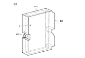
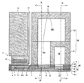
液体を吐出する液体吐出ヘッド(液滴吐出ヘッド)として、複数の個別液室内の液体を循環させる循環型ヘッドが知られている。
例えば、圧力発生室となる各個別液室に液体を供給する共通液室と、各個別液室に通じる循環流路に通じる循環共通液室とを、各個別液室及び循環流路を生成する複数の板状部材で構成される流路部材で形成したものが知られている(特許文献2及び特許文献3参照)。
As a liquid discharge head (droplet discharge head) for discharging a liquid, a circulation head that circulates liquid in a plurality of individual liquid chambers is known.
For example, a common liquid chamber that supplies a liquid to each individual liquid chamber serving as a pressure generation chamber and a circulation common liquid chamber that communicates with a circulation channel that communicates with each individual liquid chamber are generated as individual liquid chambers and circulation channels. What was formed with the flow-path member comprised with a some plate-shaped member is known (refer patent document 2 and patent document 3).
本発明は、かかる現状を鑑みてなされたものであり、長期に渡る貯蔵安定性があり、かつ高いラミネート強度が得られる被印刷物の表面処理用液体組成物を提供することを目的とする。 This invention is made | formed in view of this present condition, and it aims at providing the liquid composition for surface treatment of the to-be-printed material which is long-term storage stability and can obtain high lamination strength.
本発明は下記(1)に記載する通りの表面処理用液体組成物に係るものである。
(1)ノニオン性樹脂粒子と、多価金属塩とを含む被印刷物の表面処理用液体組成物。
The present invention relates to a liquid composition for surface treatment as described in (1) below.
(1) A liquid composition for surface treatment of a printing material containing nonionic resin particles and a polyvalent metal salt.
本発明の表面処理用液体組成物は長期に渡る貯蔵安定性を有しており、また、被印刷物の表面に塗工することにより、高いラミネート強度が得られる。 The liquid composition for surface treatment of the present invention has long-term storage stability, and a high laminate strength can be obtained by coating on the surface of the printing material.
以下、上記本発明(1)について詳しく説明する。なお、本発明(1)の実施の形態には、次の(2)〜(16)も含まれるので、これらについても併せて説明する。
(2)前記ノニオン性樹脂粒子が、ポリオレフィン樹脂、ポリ酢酸ビニル樹脂、ポリ塩化ビニル樹脂、ウレタン樹脂、スチレンブタジエン樹脂およびこれらの共重合体から選ばれる少なくとも1つの樹脂からなる前記(1)に記載の表面処理用液体組成物。
(3)前記多価金属塩が、カルシウム塩、マグネシウム塩、ニッケル塩、およびアルミニウム塩から選ばれる少なくとも1つである前記(1)又は(2)に記載の表面処理用液体組成物。
(4)前記アルミニウム塩が硫酸アルミニウム、リン酸アルミニウム、ポリ塩化アルミニウム、硫酸カリウムアルミニウムのいずれかである前記(3)に記載の表面処理用液体組成物。
(5)前記ノニオン性樹脂粒子の液体組成物全体に対する含有率が0.5〜20質量%である前記(1)〜(4)のいずれかに記載の表面処理用液体組成物。
(6)前記(1)〜(5)のいずれかに記載の表面処理用液体組成物と、色材を含むインクとからなるインクセット。
(7)前記インクが体積平均粒径が30〜110nmである非白色の色材及び熱可塑性樹脂粒子を有する前記(6)に記載のインクセット。
(8)前記インクが白色の色材及び熱可塑性樹脂粒子を有する前記(6)に記載のインクセット。
(9)体積平均粒径が30〜110nmである非白色の色材及び熱可塑性樹脂粒子を有する非白色インクと、白色の色材及び熱可塑性樹脂粒子を有する白色インクを有する前記(6)に記載のインクセット。
(10)非白色インク及び白色インクのうち、少なくとも1つのインクが、該インク中における、質量基準による前記熱可塑性樹脂粒子の含有率(R)と、前記色材の含有率(P)の比率がR/P=0.5〜3.0の範囲にある前記(9)に記載のインクセット。
(11)前記表面処理用液体組成物に含まれるノニオン性樹脂粒子のガラス転移温度Tg1が、前記インクに含まれる熱可塑性樹脂粒子のガラス転移温度Tg2よりも低い前記(6)〜(10)のいずれかに記載のインクセット。
(12)被印刷物に表面処理用液体組成物を付与する工程と、インクを吐出する印刷工程とを有する記録方法であって、前記表面処理用液体組成物およびインクとして、前記(6)〜(11)のいずれかに記載のインクセットを用いる記録方法。
(13)被印刷物を表面改質する表面改質工程を有する前記(12)に記載の記録方法。
(14)前記印刷工程が、インクを吐出するノズルと、前記ノズルに連通する複数の個別液室と、インクを個別液室に流入させるための流入流路と、インクを前記個別液室から流出させるための流出流路と、を有するインク吐出ヘッドを用い、インクを吐出して印刷する印刷工程であり、更に、前記インクを前記流出流路から前記流入流路に向かって循環させる循環工程とを含む前記(12)又は(13)に記載の記録方法。
(15)前記(6)〜(11)のいずれかに記載のインクセットと、前記インクセットのインクを吐出させるインク吐出ヘッドとを有する記録装置。
(16)前記インク吐出ヘッドが、インクを吐出するノズル、前記ノズルに連通する複数の個別液室と、前記個別液室にインクを流入させるための流入流路と、インクを前記個別液室から流出させるための流出流路と、を有し、更に、前記インクを前記流出流路から前記流入流路に向かって循環させる循環手段を備えている前記(15)に記載の記録装置。
Hereinafter, the present invention (1) will be described in detail. In addition, since following (2)-(16) is also included in embodiment of this invention (1), these are also demonstrated collectively.
(2) The nonionic resin particles according to (1), wherein the nonionic resin particles are made of at least one resin selected from polyolefin resins, polyvinyl acetate resins, polyvinyl chloride resins, urethane resins, styrene butadiene resins, and copolymers thereof. A liquid composition for surface treatment.
(3) The liquid composition for surface treatment according to (1) or (2), wherein the polyvalent metal salt is at least one selected from a calcium salt, a magnesium salt, a nickel salt, and an aluminum salt.
(4) The liquid composition for surface treatment according to (3), wherein the aluminum salt is any one of aluminum sulfate, aluminum phosphate, polyaluminum chloride, and potassium aluminum sulfate.
(5) The liquid composition for surface treatment according to any one of (1) to (4), wherein a content ratio of the nonionic resin particles to the entire liquid composition is 0.5 to 20% by mass.
(6) An ink set comprising the surface treatment liquid composition according to any one of (1) to (5) and an ink containing a color material.
(7) The ink set according to (6), wherein the ink includes a non-white color material having a volume average particle diameter of 30 to 110 nm and thermoplastic resin particles.
(8) The ink set according to (6), wherein the ink includes a white color material and thermoplastic resin particles.
(9) In the above (6), having a non-white ink having a non-white color material and thermoplastic resin particles having a volume average particle diameter of 30 to 110 nm, and a white ink having a white color material and thermoplastic resin particles The ink set described.
(10) The ratio of the content ratio (R) of the thermoplastic resin particles and the content ratio (P) of the colorant on a mass basis in at least one of the non-white ink and the white ink The ink set according to (9), wherein R / P is in the range of 0.5 to 3.0.
(11) The glass transition temperature Tg1 of the nonionic resin particles contained in the surface treatment liquid composition is lower than the glass transition temperature Tg2 of the thermoplastic resin particles contained in the ink. The ink set according to any one of the above.
(12) A recording method comprising a step of applying a surface treatment liquid composition to a substrate and a printing step of discharging ink, wherein the surface treatment liquid composition and the ink are (6) to (6) A recording method using the ink set according to any one of 11).
(13) The recording method according to (12), further including a surface modification step for modifying the surface of the printing material.
(14) The printing process includes a nozzle for ejecting ink, a plurality of individual liquid chambers communicating with the nozzle, an inflow channel for allowing ink to flow into the individual liquid chamber, and the ink flowing out from the individual liquid chamber. An outflow passage for causing the ink to flow, and a printing step for discharging and printing ink, and a circulation step for circulating the ink from the outflow passage toward the inflow passage. The recording method according to (12) or (13), comprising:
(15) A recording apparatus comprising: the ink set according to any one of (6) to (11); and an ink ejection head that ejects ink of the ink set.
(16) The ink ejection head includes a nozzle for ejecting ink, a plurality of individual liquid chambers communicating with the nozzle, an inflow channel for allowing ink to flow into the individual liquid chamber, and ink from the individual liquid chamber. The recording apparatus according to (15), further including a circulation unit configured to circulate the ink from the outflow channel toward the inflow channel.
本発明の被印刷物の表面を処理するための表面処理用液体組成物はノニオン性樹脂粒子と、多価金属塩を含む。なお、色材は実質的に含まない。実質的に色材を含まないとは、表面処理用液体組成物(以下では単に「液体組成物」ということがある。)の成分として積極的に色材を添加することはしないということを意味する。
本発明者らは、多価金属塩との共存下における樹脂粒子の長期的な保存安定のためには一般的に用いられている電荷反発型エマルションではなく、立体障害で分散したノニオン性樹脂粒子によって達成できることを見出して本発明を完成した。
電荷反発型の中でもアニオン型樹脂粒子の場合、多価金属塩と混合すると凝集することが分かり、特に多価金属塩の中でも電離すると3価の陽イオンを生じる多価金属塩は瞬時に凝集することが分かった。価数が大きい陽イオンほど早く多量に凝集を促し、分散物を塩析させる効果が高い。
カチオン型樹脂粒子では常温放置程度では充分に安定であるが、長期安定性を見越した加速試験として加温下で静置すると、やはり増粘が見られる結果となった。
The surface treatment liquid composition for treating the surface of the printing material of the present invention contains nonionic resin particles and a polyvalent metal salt. In addition, a coloring material is not included substantially. The phrase “substantially free of coloring material” means that the coloring material is not positively added as a component of the surface treatment liquid composition (hereinafter sometimes simply referred to as “liquid composition”). To do.
The present inventors are not a charge repulsion type emulsion generally used for long-term storage stability of resin particles in the presence of a polyvalent metal salt, but nonionic resin particles dispersed by steric hindrance. Thus, the present invention has been completed.
In the case of anionic resin particles among the charge repulsion type, it is found that when mixed with a polyvalent metal salt, the polyvalent metal salt that produces a trivalent cation when ionized is agglomerated instantly. I understood that. The higher the valence, the faster the flocculation is promoted and the higher the effect of salting out the dispersion.
The cationic resin particles are sufficiently stable when left at room temperature, but when they are allowed to stand under heating as an accelerated test in anticipation of long-term stability, thickening is still observed.
前記ノニオン性樹脂粒子が、ポリオレフィン樹脂、ポリ酢酸ビニル樹脂、ポリ塩化ビニル樹脂、ウレタン樹脂、スチレンブタジエン樹脂およびこれらの樹脂の共重合体から選ばれる少なくとも1つであるとき、強い基材密着性により特に優れたラミネート適性が得られるため好適である。 When the nonionic resin particles are at least one selected from polyolefin resins, polyvinyl acetate resins, polyvinyl chloride resins, urethane resins, styrene butadiene resins, and copolymers of these resins, This is particularly preferable because excellent laminating properties can be obtained.
前記多価金属塩が、カルシウム塩、マグネシウム塩、ニッケル塩、およびアルミニウム塩から選ばれる少なくとも1つであるとき、特に優れたインク滴凝集効果によりネガ文字潰れを抑制でき、さらに優れた貯蔵安定性の観点からも好適である。
前記多価金属塩が、アルミニウム塩であるとき、特に優れたインク滴凝集効果によりネガ文字潰れを抑制できる。加えてアルミニウムイオンはイオンとして安定で、鉄(III)イオンのように酸化により価数が変化しない。
When the polyvalent metal salt is at least one selected from calcium salt, magnesium salt, nickel salt, and aluminum salt, negative character crushing can be suppressed due to particularly excellent ink droplet aggregation effect, and further excellent storage stability. From the viewpoint of this, it is also preferable.
When the polyvalent metal salt is an aluminum salt, negative character crushing can be suppressed by a particularly excellent ink droplet aggregation effect. In addition, aluminum ions are stable as ions, and the valence does not change by oxidation like iron (III) ions.
前記ノニオン性樹脂粒子の液体組成物全体に対する含有率が0.5〜20質量%であるとき、充分な樹脂量が確保でき、かつ膜厚増による内部応力が抑えられるため非印字部のラミネート強度が特に優れたものとなるため好適である。 When the content of the nonionic resin particles relative to the entire liquid composition is 0.5 to 20% by mass, a sufficient amount of resin can be secured, and internal stress due to an increase in film thickness can be suppressed, so that the laminate strength of the non-printing portion Is particularly preferable because it is excellent.
前記多価金属塩の液体組成物全体に対する濃度が0.05〜0.5モル/kgであるとき、特に優れた貯蔵安定性とともに、ネガ文字潰れが抑えられるため好適である。 When the concentration of the polyvalent metal salt relative to the entire liquid composition is 0.05 to 0.5 mol / kg, it is preferable because negative character crushing can be suppressed along with particularly excellent storage stability.
前記ノニオン性樹脂粒子のガラス転移温度が−25〜25℃であるとき、適度な柔軟性となるため、ラミネート強度と耐擦過性のバランスに優れたものとなるため好適である。 When the glass transition temperature of the nonionic resin particles is −25 to 25 ° C., it is suitable because it has an appropriate flexibility and thus has an excellent balance between laminate strength and scratch resistance.
前記表面処理用液体組成物と、色材を含むインクとからなるインクセットであるとき、耐擦過性と画像濃度に優れた印字物が得られるため好適である。 An ink set comprising the surface treatment liquid composition and an ink containing a color material is preferable because a printed matter having excellent scratch resistance and image density can be obtained.
前記インクセットは、前記インクが、樹脂粒子を有するインクであり、非白色インクを有し、該非白色インクは、前記色材が体積平均粒径が30〜110nmである非白色の色材であり、樹脂粒子が熱可塑性樹脂粒子であるインクセットであるとき、特に発色性に優れ、高濃度が得られるため好適である。
前記インクセットは、前記インクが、樹脂粒子を有するインクであり、白色インクを有し、該白色インクは、前記色材が白色の色材であり、前記樹脂粒子が熱可塑性樹脂粒子であるインクセットであるとき、特に発色性に優れ、高濃度が得られるため好適である。
前記インクセットは、前記インクが、樹脂粒子を有するインクであり、白色インクと非白色インクとを有し、該白色インクは、前記色材が白色の色材であって、前記樹脂粒子が熱可塑性樹脂粒子であり、該非白色インクは、前記色材が体積平均粒径が30〜110nmである非白色の色材であり、前記樹脂粒子が熱可塑性樹脂粒子であるインクセットであるとき、特に発色性に優れ、高濃度が得られ、色域に優れるため好適である。
In the ink set, the ink is an ink having resin particles and has a non-white ink, and the non-white ink is a non-white color material having a volume average particle diameter of 30 to 110 nm. The ink set in which the resin particles are thermoplastic resin particles is preferable because it is particularly excellent in color developability and a high concentration can be obtained.
In the ink set, the ink is an ink having resin particles, and has a white ink. The white ink is an ink in which the color material is a white color material and the resin particles are thermoplastic resin particles. When it is a set, it is particularly preferable because it is excellent in color developability and a high concentration can be obtained.
In the ink set, the ink is an ink having resin particles, and includes a white ink and a non-white ink. The white ink is a white color material, and the resin particles are heated. When the non-white ink is a plastic resin particle, and the non-white ink is an ink set in which the color material is a non-white color material having a volume average particle size of 30 to 110 nm, and the resin particle is a thermoplastic resin particle, It is suitable because of excellent color developability, high density, and excellent color gamut.
前記樹脂粒子が、アクリル樹脂、ウレタン樹脂、ポリエステル樹脂から選ばれる少なくとも1つであるインクセットであるとき、優れた耐擦過性が得られるため好適である。 When the resin particle is an ink set that is at least one selected from an acrylic resin, a urethane resin, and a polyester resin, it is preferable because excellent scratch resistance is obtained.
前記インクは樹脂粒子を有するインクであり、質量基準による前記樹脂粒子の含有率(R)と前記色材の含有率(P)の比率がR/P=0.5〜3.0の範囲にあるインクセットであるとき、さらに優れた耐擦過性が得られるため好適である。
白色インクについて、質量基準による前記樹脂粒子の含有率(R)と前記色材の含有率(P)の比率をR/P=0.5〜3.0の範囲とすることもでき、非白色インクについて質量基準による前記樹脂粒子の含有率(R)と前記色材の含有率(P)の比率をR/P=0.5〜3.0の範囲としても良く、白色インクと非白色インクの両方について、質量基準による前記樹脂粒子の含有率(R)と前記色材の含有率(P)の比率をR/P=0.5〜3.0の範囲としても良い。
The ink is an ink having resin particles, and the ratio of the resin particle content (R) to the colorant content (P) based on mass is in the range of R / P = 0.5 to 3.0. When an ink set is used, it is preferable because more excellent scratch resistance can be obtained.
For the white ink, the ratio of the resin particle content (R) and the colorant content (P) on a mass basis can also be in the range of R / P = 0.5 to 3.0. The ratio of the resin particle content (R) and the colorant content (P) on a mass basis for the ink may be in the range of R / P = 0.5 to 3.0. White ink and non-white ink In both cases, the ratio of the resin particle content (R) and the colorant content (P) on a mass basis may be in the range of R / P = 0.5 to 3.0.
前記表面処理用液体組成物に含まれるノニオン性樹脂粒子のガラス転移温度Tg1が、前記インクに含まれる樹脂粒子のガラス転移温度Tg2よりも低いインクセットであるとき、印字部のラミネート強度が優れたものとなるため好適である。 When the glass transition temperature Tg1 of the nonionic resin particles contained in the liquid composition for surface treatment is an ink set lower than the glass transition temperature Tg2 of the resin particles contained in the ink, the laminate strength of the printed portion was excellent. Since it becomes a thing, it is suitable.
記録方法が、被印刷物(以下「記録媒体」ということもある)を表面改質する表面改質工程と、前記表面処理用液体組成物を被印刷物に付与する表面処理用液体組成物付与工程と、前記インクを被印刷物に付与するインク付与工程を有するとき、印字部および非印字部のラミネート強度が向上するため好ましく、さらに表面改質工程がコロナ放電処理又はストリーマ放電処理であるときさらに向上するため好適である。 A recording method includes a surface modification step for modifying a surface of a printing material (hereinafter also referred to as “recording medium”), and a surface treatment liquid composition applying step for applying the surface treatment liquid composition to the printing material. In addition, when the ink application step for applying the ink to the printing material is included, the laminate strength of the printing portion and the non-printing portion is preferably improved, and further improved when the surface modification step is a corona discharge treatment or a streamer discharge treatment. Therefore, it is preferable.
前記記録方法が、更に印字後に加熱処理工程を有するとき、熱によりインク中の熱可塑性樹脂の造膜が促され、耐擦過性が向上するため望ましい。 When the recording method further includes a heat treatment step after printing, it is preferable because the film formation of a thermoplastic resin in the ink is promoted by heat, and the scratch resistance is improved.
前記表面処理用液体組成物付与工程において、液体組成物の付着量が0.4〜2g/m2であるとき、ネガ文字つぶれとラミネート強度の両立が図りやすい為好適である。 In the surface treatment liquid composition application step, when the adhesion amount of the liquid composition is 0.4 to 2 g / m 2, it is preferable because both negative character crushing and laminate strength can be easily achieved.
前記インク付与工程において、インクの付着量が4〜14g/m2であるとき、画像濃度と速乾性の両立が図りやすいため好適である。 In the ink application step, when the ink adhesion amount is 4 to 14 g / m 2, it is preferable because it is easy to achieve both image density and quick drying.
記録方法が、インクを被印刷物に付与するインク付与工程として、前記非白色インクを被印刷物に付与するインク付与工程と、前記白色インクを被印刷物に付与するインク付与工程を有するとき、広い色域と高濃度の画像が得られるため好適である。 A wide color gamut when the recording method includes an ink applying step for applying the non-white ink to the printing material and an ink applying step for applying the white ink to the printing material as an ink applying step for applying ink to the printing material. This is preferable because an image with a high density can be obtained.
以下、本発明の液体組成物の構成成分であるノニオン性樹脂粒子及び多価金属塩について説明する。 Hereinafter, the nonionic resin particles and the polyvalent metal salt, which are components of the liquid composition of the present invention, will be described.
<ノニオン性樹脂粒子>
本発明におけるノニオン性樹脂粒子とは、電荷を利用せずとも分散可能な樹脂粒子である。
本発明におけるノニオン性樹脂粒子とは、液体組成物から遠心分離により固形分を単離後、熱分解GC−MS(例えば、島津製作所製GC−17Aなど)により、カルボキシル基、スルホ基などの酸性官能基、あるいはアミノ基などの塩基性官能基を含有するモノマーが検出されない樹脂微粒子を指す。
樹脂粒子の化学構造に特に限定はなく、ノニオン分散可能な樹脂粒子であればどのようなものでも使用することが出来るが、ポリオレフィン樹脂、ポリ酢酸ビニル樹脂、ポリ塩化ビニル樹脂、ウレタン樹脂、スチレンブタジエン樹脂およびこれらの樹脂の共重合体から選ばれる少なくとも1つであるとき、様々な基材に対する強固な密着性が得られるため好ましく、さらにエチレン−酢酸ビニル共重合樹脂、エチレン−酢酸ビニル−塩化ビニル共重合樹脂、オレフィン変性ウレタン樹脂であることがさらに好ましい。
<Nonionic resin particles>
The nonionic resin particles in the present invention are resin particles that can be dispersed without using electric charges.
The nonionic resin particle in the present invention is an acid such as a carboxyl group or a sulfo group by pyrolysis GC-MS (for example, GC-17A manufactured by Shimadzu Corporation) after solid content is isolated from the liquid composition by centrifugation. It refers to resin fine particles in which a monomer containing a functional group or a basic functional group such as an amino group is not detected.
There is no particular limitation on the chemical structure of the resin particles, and any nonionic-dispersible resin particles can be used. However, polyolefin resins, polyvinyl acetate resins, polyvinyl chloride resins, urethane resins, styrene butadienes can be used. When it is at least one selected from resins and copolymers of these resins, it is preferable because strong adhesion to various substrates can be obtained. Further, ethylene-vinyl acetate copolymer resins, ethylene-vinyl acetate-vinyl chloride are preferable. More preferably, it is a copolymer resin or an olefin-modified urethane resin.
ノニオン性樹脂粒子のガラス転移温度Tgは−30〜30℃であることが好ましく、また、−25〜25℃であることがより好ましい。
Tgが−30℃以上であれば樹脂皮膜が十分強靭なものとなり、先塗り層がより堅牢なものとなり、30℃以下であれば樹脂の成膜性が向上し、充分な柔軟性も担保されるため基材密着性が強固なものとなり好ましい。
The glass transition temperature Tg of the nonionic resin particles is preferably −30 to 30 ° C., and more preferably −25 to 25 ° C.
If Tg is −30 ° C. or higher, the resin film is sufficiently tough, and the pre-coating layer is more robust, and if it is 30 ° C. or lower, the film-forming property of the resin is improved and sufficient flexibility is ensured. Therefore, the substrate adhesion is strong and preferable.
添加量は液体組成物総量に対して固形分として0.5質量%以上20質量%以下となるように添加することが好ましい。
0.5質量%以上で樹脂が充分に基材を被覆することが出来るため密着性が向上し、20質量%以下であれば膜厚が厚くなりすぎないため密着性の低下の恐れが無い。
The amount added is preferably 0.5% by mass or more and 20% by mass or less as a solid content with respect to the total amount of the liquid composition.
Since the resin can sufficiently cover the substrate at 0.5% by mass or more, the adhesiveness is improved, and when it is 20% by mass or less, the film thickness does not become too thick and there is no fear of lowering the adhesion.
<多価金属塩>
多価金属塩はインク中の色材を着滴後に速やかに凝集させ、ネガ文字潰れを抑制するとともに、発色性を向上させる。
多価金属塩としては、以下に限定されないが、例えば、チタン、クロム、銅、コバルト、ストロンチウム、バリウム、鉄、アルミニウム、カルシウム、マグネシウム及びニッケルの塩(多価金属塩)が挙げられる。
<Multivalent metal salt>
The polyvalent metal salt quickly aggregates the coloring material in the ink after landing, suppresses negative character crushing, and improves color developability.
Examples of the polyvalent metal salt include, but are not limited to, salts of titanium, chromium, copper, cobalt, strontium, barium, iron, aluminum, calcium, magnesium, and nickel (polyvalent metal salt).
これら多価金属塩の中でも、顔料を効果的に凝集させることができるため、カルシウム塩、マグネシウム塩、ニッケル塩、アルミニウム塩からなる群より選択される一種以上が好ましく、2価の陽イオンを電離により生じるカルシウムやマグネシウム等のアルカリ土類金属塩がより好ましい。
また、3価の陽イオンを電離により生じるアルミニウムや鉄等の金属塩が好ましく、アルミニウム塩がより好ましい。
特に、上記多価金属塩がカルシウム塩、アルミニウム塩である場合、反応液の安定性がより良好となる。
Among these polyvalent metal salts, at least one selected from the group consisting of calcium salts, magnesium salts, nickel salts, and aluminum salts is preferable because the pigment can be effectively aggregated, and the divalent cation is ionized. More preferred are alkaline earth metal salts such as calcium and magnesium.
Moreover, metal salts, such as aluminum and iron which produce | generate a trivalent cation by ionization, are preferable, and aluminum salt is more preferable.
In particular, when the polyvalent metal salt is a calcium salt or an aluminum salt, the stability of the reaction solution becomes better.
上記の多価金属塩の具体例としては、炭酸カルシウム、硝酸カルシウム、塩化カルシウム、酢酸カルシウム、硫酸カルシウム、塩化マグネシウム、酢酸マグネシウム、硫酸マグネシウム、塩化ニッケル、硫酸バリウム、硫化亜鉛、炭酸亜鉛、珪酸アルミニウム、珪酸カルシウム、珪酸マグネシウム、水酸化アルミニウム、硫酸アルミニウム、リン酸アルミニウム、乳酸アルミニウム、ポリ塩化アルミニウム、硫酸鉄(III)、硫酸カリウムアルミニウム、カリウム鉄ミョウバン、アンモニウム鉄ミョウバンなどが挙げられる。
これらの中でも、潮解性による先塗り層の強度低下を防ぐ目的で酢酸カルシウム、硫酸アルミニウムが好ましい。
Specific examples of the polyvalent metal salt include calcium carbonate, calcium nitrate, calcium chloride, calcium acetate, calcium sulfate, magnesium chloride, magnesium acetate, magnesium sulfate, nickel chloride, barium sulfate, zinc sulfide, zinc carbonate, aluminum silicate. , Calcium silicate, magnesium silicate, aluminum hydroxide, aluminum sulfate, aluminum phosphate, aluminum lactate, polyaluminum chloride, iron (III) sulfate, potassium aluminum sulfate, potassium iron alum, ammonium iron alum and the like.
Among these, calcium acetate and aluminum sulfate are preferable for the purpose of preventing a decrease in strength of the first coat layer due to deliquescence.
前記多価金属塩の液体組成物全体に対する濃度が0.05〜0.5モル/kgであるとき、特に優れた貯蔵安定性とともに、ネガ文字潰れが抑制されるため好適である。 When the concentration of the polyvalent metal salt relative to the entire liquid composition is 0.05 to 0.5 mol / kg, it is preferable because negative character crushing is suppressed as well as particularly excellent storage stability.
本発明の液体組成物の媒体は、水性媒体であるが、必要に応じて水以外のものを添加しても良く、そのようなものとして例えば水溶性有機溶剤、界面活性剤、その他微量添加剤などが挙げられる。 The medium of the liquid composition of the present invention is an aqueous medium, but other than water may be added if necessary, such as a water-soluble organic solvent, a surfactant, and other trace additives. Etc.
<有機溶剤>
本発明に使用する有機溶剤としては特に制限されず、水溶性有機溶剤を用いることができる。例えば、多価アルコール類、多価アルコールアルキルエーテル類や多価アルコールアリールエーテル類などのエーテル類、含窒素複素環化合物、アミド類、アミン類、含硫黄化合物類が挙げられる。
水溶性有機溶剤の具体例としては、例えば、エチレングリコール、ジエチレングリコール、1,2−プロパンジオール、1,3−プロパンジオール、1,2−ブタンジオール、1,3−ブタンジオール、1,4−ブタンジオール、2,3−ブタンジオール、3−メチル−1,3−ブタンジオール、トリエチレングリコール、ポリエチレングリコール、ポリプロピレングリコール、1,2−ペンタンジオール、1,3−ペンタンジオール、1,4−ペンタンジオール、2,4−ペンタンジオール、1,5−ペンタンジオール、1,2−ヘキサンジオール、1,6−ヘキサンジオール、1,3−ヘキサンジオール、2,5−ヘキサンジオール、1,5−ヘキサンジオール、グリセリン、1,2,6−ヘキサントリオール、2−エチル−1,3−ヘキサンジオール、エチル−1,2,4−ブタントリオール、1,2,3−ブタントリオール、2,2,4−トリメチル−1,3−ペンタンジオール、ペトリオール等の多価アルコール類、エチレングリコールモノエチルエーテル、エチレングリコールモノブチルエーテル、ジエチレングリコールモノメチルエーテル、ジエチレングリコールモノエチルエーテル、ジエチレングリコールモノブチルエーテル、テトラエチレングリコールモノメチルエーテル、プロピレングリコールモノエチルエーテル等の多価アルコールアルキルエーテル類、エチレングリコールモノフェニルエーテル、エチレングリコールモノベンジルエーテル等の多価アルコールアリールエーテル類、2−ピロリドン、N−メチル−2−ピロリドン、N−ヒドロキシエチル−2−ピロリドン、1,3−ジメチル−2−イミダゾリジノン、ε−カプロラクタム、γ−ブチロラクトン等の含窒素複素環化合物、ホルムアミド、N−メチルホルムアミド、N,N−ジメチルホルムアミド、3−メトキシ−N,N−ジメチルプロピオンアミド、3−ブトキシ−N,N−ジメチルプロピオンアミド等のアミド類、モノエタノールアミン、ジエタノールアミン、トリエチルアミン等のアミン類、ジメチルスルホキシド、スルホラン、チオジエタノール等の含硫黄化合物、プロピレンカーボネート、炭酸エチレン等が挙げられる。
湿潤剤として機能するだけでなく、良好な乾燥性を得られることから、沸点が250℃以下の有機溶剤を用いることが好ましい。
<Organic solvent>
The organic solvent used in the present invention is not particularly limited, and a water-soluble organic solvent can be used. Examples thereof include ethers such as polyhydric alcohols, polyhydric alcohol alkyl ethers and polyhydric alcohol aryl ethers, nitrogen-containing heterocyclic compounds, amides, amines and sulfur-containing compounds.
Specific examples of the water-soluble organic solvent include, for example, ethylene glycol, diethylene glycol, 1,2-propanediol, 1,3-propanediol, 1,2-butanediol, 1,3-butanediol, and 1,4-butane. Diol, 2,3-butanediol, 3-methyl-1,3-butanediol, triethylene glycol, polyethylene glycol, polypropylene glycol, 1,2-pentanediol, 1,3-pentanediol, 1,4-pentanediol 2,4-pentanediol, 1,5-pentanediol, 1,2-hexanediol, 1,6-hexanediol, 1,3-hexanediol, 2,5-hexanediol, 1,5-hexanediol, Glycerin, 1,2,6-hexanetriol, 2-ethyl-1,3-he Polyhydric alcohols such as sundiol, ethyl-1,2,4-butanetriol, 1,2,3-butanetriol, 2,2,4-trimethyl-1,3-pentanediol, petriol, ethylene glycol mono Polyhydric alcohol alkyl ethers such as ethyl ether, ethylene glycol monobutyl ether, diethylene glycol monomethyl ether, diethylene glycol monoethyl ether, diethylene glycol monobutyl ether, tetraethylene glycol monomethyl ether, propylene glycol monoethyl ether, ethylene glycol monophenyl ether, ethylene glycol mono Polyhydric alcohol aryl ethers such as benzyl ether, 2-pyrrolidone, N-methyl-2-pyrrolidone, N-hydroxyethyl- -N-containing heterocyclic compounds such as pyrrolidone, 1,3-dimethyl-2-imidazolidinone, ε-caprolactam, γ-butyrolactone, formamide, N-methylformamide, N, N-dimethylformamide, 3-methoxy-N, Amides such as N-dimethylpropionamide and 3-butoxy-N, N-dimethylpropionamide, amines such as monoethanolamine, diethanolamine and triethylamine, sulfur-containing compounds such as dimethylsulfoxide, sulfolane and thiodiethanol, propylene carbonate, Examples thereof include ethylene carbonate.
In addition to functioning as a wetting agent, it is preferable to use an organic solvent having a boiling point of 250 ° C. or lower because good drying properties can be obtained.
有機溶剤の液体組成物中における含有量は、特に制限はなく、目的に応じて適宜選択することができるが、液体組成物の乾燥性及び吐出信頼性の点から、5質量%以上60質量%以下が好ましく、10質量%以上30質量%以下がより好ましく、10質量%以上25質量%以下がさらに好ましい。 The content of the organic solvent in the liquid composition is not particularly limited and may be appropriately selected depending on the intended purpose. From the viewpoint of the drying property and ejection reliability of the liquid composition, the content is 5% by mass or more and 60% by mass. The following is preferable, 10 mass% or more and 30 mass% or less are more preferable, and 10 mass% or more and 25 mass% or less are more preferable.
また、液体組成物が有機溶剤として1,2−プロパンジオール、1,2−ブタンジオール、2,3−ブタンジオールのうちいずれかを含有する場合、樹脂の造膜性が向上し、さらに耐擦過性が向上するので好ましい。 Further, when the liquid composition contains any one of 1,2-propanediol, 1,2-butanediol, and 2,3-butanediol as an organic solvent, the film-forming property of the resin is improved, and the scratch resistance is further increased. This is preferable because of improved properties.
<界面活性剤>
界面活性剤としては、シリコーン系界面活性剤、フッ素系界面活性剤、両性界面活性剤、ノニオン系界面活性剤、アニオン系界面活性剤のいずれも使用可能である。
シリコーン系界面活性剤には特に制限はなく目的に応じて適宜選択することができる。
中でも高pHでも分解しないものが好ましく、例えば、側鎖変性ポリジメチルシロキサン、両末端変性ポリジメチルシロキサン、片末端変性ポリジメチルシロキサン、側鎖両末端変性ポリジメチルシロキサン等が挙げられ、変性基としてポリオキシエチレン基、ポリオキシエチレンポリオキシプロピレン基を有するものが、水系界面活性剤として良好な性質を示すので特に好ましい。また、前記シリコーン系界面活性剤として、ポリエーテル変性シリコーン系界面活性剤を用いることもでき、例えば、ポリアルキレンオキシド構造をジメチルシロキサンのSi部側鎖に導入した化合物等が挙げられる。
フッ素系界面活性剤としては、例えば、パーフルオロアルキルスルホン酸化合物、パーフルオロアルキルカルボン酸化合物、パーフルオロアルキルリン酸エステル化合物、パーフルオロアルキルエチレンオキサイド付加物及びパーフルオロアルキルエーテル基を側鎖に有するポリオキシアルキレンエーテルポリマー化合物が、起泡性が小さいので特に好ましい。前記パーフルオロアルキルスルホン酸化合物としては、例えば、パーフルオロアルキルスルホン酸、パーフルオロアルキルスルホン酸塩等が挙げられる。前記パーフルオロアルキルカルボン酸化合物としては、例えば、パーフルオロアルキルカルボン酸、パーフルオロアルキルカルボン酸塩等が挙げられる。前記パーフルオロアルキルエーテル基を側鎖に有するポリオキシアルキレンエーテルポリマー化合物としては、パーフルオロアルキルエーテル基を側鎖に有するポリオキシアルキレンエーテルポリマーの硫酸エステル塩、パーフルオロアルキルエーテル基を側鎖に有するポリオキシアルキレンエーテルポリマーの塩等が挙げられる。これらフッ素系界面活性剤における塩の対イオンとしては、Li、Na、K、NH4、NH3CH2CH2OH、NH2(CH2CH2OH)2、NH(CH2CH2OH)3等が挙げられる。
両性界面活性剤としては、例えばラウリルアミノプロピオン酸塩、ラウリルジメチルベタイン、ステアリルジメチルベタイン、ラウリルジヒドロキシエチルベタインなどが挙げられる。
ノニオン系界面活性剤としては、例えば、ポリオキシエチレンアルキルフェニルエーテル、ポリオキシエチレンアルキルエステル、ポリオキシエチレンアルキルアミン、ポリオキシエチレンアルキルアミド、ポリオキシエチレンプロピレンブロックポリマー、ソルビタン脂肪酸エステル、ポリオキシエチレンソルビタン脂肪酸エステル、アセチレンアルコールのエチレンオキサイド付加物などが挙げられる。
アニオン系界面活性剤としては、例えば、ポリオキシエチレンアルキルエーテル酢酸塩、ドデシルベンゼンスルホン酸塩、ラウリル酸塩、ポリオキシエチレンアルキルエーテルサルフェートの塩、などが挙げられる。
これらは、1種を単独で用いても、2種以上を併用してもよい。
<Surfactant>
As the surfactant, any of silicone surfactants, fluorine surfactants, amphoteric surfactants, nonionic surfactants and anionic surfactants can be used.
There is no restriction | limiting in particular in silicone type surfactant, According to the objective, it can select suitably.
Among them, those that do not decompose even at high pH are preferable, and examples thereof include side chain modified polydimethylsiloxane, both terminal modified polydimethylsiloxane, one terminal modified polydimethylsiloxane, and side chain both terminal modified polydimethylsiloxane. Those having an oxyethylene group or a polyoxyethylene polyoxypropylene group are particularly preferred because they exhibit good properties as an aqueous surfactant. In addition, as the silicone surfactant, a polyether-modified silicone surfactant can be used, and examples thereof include a compound in which a polyalkylene oxide structure is introduced into the side chain of the Si portion of dimethylsiloxane.
Examples of the fluorosurfactant include a perfluoroalkyl sulfonic acid compound, a perfluoroalkyl carboxylic acid compound, a perfluoroalkyl phosphate compound, a perfluoroalkyl ethylene oxide adduct, and a perfluoroalkyl ether group in the side chain. Polyoxyalkylene ether polymer compounds are particularly preferred because of their low foaming properties. Examples of the perfluoroalkyl sulfonic acid compound include perfluoroalkyl sulfonic acid, perfluoroalkyl sulfonate, and the like. Examples of the perfluoroalkylcarboxylic acid compound include perfluoroalkylcarboxylic acid and perfluoroalkylcarboxylate. Examples of the polyoxyalkylene ether polymer compound having a perfluoroalkyl ether group in the side chain include a sulfate ester salt of a polyoxyalkylene ether polymer having a perfluoroalkyl ether group in the side chain and a perfluoroalkyl ether group in the side chain. Examples thereof include salts of polyoxyalkylene ether polymers. As counter ions of the salts in these fluorosurfactants, Li, Na, K, NH 4 , NH 3 CH 2 CH 2 OH, NH 2 (CH 2 CH 2 OH) 2 , NH (CH 2 CH 2 OH) 3 etc. are mentioned.
Examples of amphoteric surfactants include lauryl aminopropionate, lauryl dimethyl betaine, stearyl dimethyl betaine, and lauryl dihydroxyethyl betaine.
Nonionic surfactants include, for example, polyoxyethylene alkylphenyl ether, polyoxyethylene alkyl ester, polyoxyethylene alkylamine, polyoxyethylene alkylamide, polyoxyethylene propylene block polymer, sorbitan fatty acid ester, polyoxyethylene sorbitan Examples include fatty acid esters and ethylene oxide adducts of acetylene alcohol.
Examples of the anionic surfactant include polyoxyethylene alkyl ether acetate, dodecylbenzene sulfonate, laurate, polyoxyethylene alkyl ether sulfate salt, and the like.
These may be used alone or in combination of two or more.
その他の微量添加剤としては、消泡剤、防腐防黴剤、防錆剤などを含有してよい。 Other trace additives may contain antifoaming agents, antiseptic / antifungal agents, rustproofing agents, and the like.
<消泡剤>
消泡剤としては、特に制限はなく、例えば、シリコーン系消泡剤、ポリエーテル系消泡剤、脂肪酸エステル系消泡剤などが挙げられる。これらは、1種を単独で用いても、2種以上を併用してもよい。これらの中でも、破泡効果に優れる点から、シリコーン系消泡剤が好ましい。
<Antifoaming agent>
There is no restriction | limiting in particular as an antifoamer, For example, a silicone type antifoamer, a polyether type | system | group antifoamer, a fatty-acid ester type | system | group antifoamer etc. are mentioned. These may be used alone or in combination of two or more. Among these, a silicone type antifoaming agent is preferable from the viewpoint of excellent foam breaking effect.
<防腐防黴剤>
防腐防黴剤としては、特に制限はなく、例えば、1,2−ベンズイソチアゾリン−3−オンなどが挙げられる。
<Antiseptic and antifungal agent>
The antiseptic / antifungal agent is not particularly limited, and examples thereof include 1,2-benzisothiazolin-3-one.
<防錆剤>
防錆剤としては、特に制限はなく、例えば、酸性亜硫酸塩、チオ硫酸ナトリウムなどが挙げられる。
<Rust preventive>
There is no restriction | limiting in particular as a rust preventive agent, For example, acidic sulfite, sodium thiosulfate, etc. are mentioned.
<インク>
次に、本発明のインクについて説明する。
インクは、色材を含む。インクは、更に樹脂粒子を含むことが好ましい。
<Ink>
Next, the ink of the present invention will be described.
The ink includes a color material. The ink preferably further contains resin particles.
<樹脂粒子>
樹脂粒子の体積平均粒径としては、特に制限はなく、目的に応じて適宜選択することができるが、良好な定着性、高い画像硬度を得る点から、10nm以上1,000nm以下が好ましく、10nm以上200nm以下がより好ましく、10nm以上100nm以下が特に好ましい。
前記体積平均粒径は、例えば、粒度分析装置(ナノトラック Wave−UT151、マイクロトラック・ベル株式会社製)を用いて測定することができる。
<Resin particles>
The volume average particle diameter of the resin particles is not particularly limited and may be appropriately selected depending on the intended purpose, but is preferably 10 nm or more and 1,000 nm or less from the viewpoint of obtaining good fixability and high image hardness. It is more preferably 200 nm or less and particularly preferably 10 nm or more and 100 nm or less.
The volume average particle diameter can be measured using, for example, a particle size analyzer (Nanotrack Wave-UT151, manufactured by Microtrack Bell Co., Ltd.).
樹脂の含有量としては、特に制限はなく、目的に応じて適宜選択することができるが、定着性、インクの保存安定性の点から、インク全量に対して、1質量%以上30質量%以下が好ましく、5質量%以上20質量%以下がより好ましい。 The resin content is not particularly limited and may be appropriately selected according to the purpose. However, from the viewpoint of fixability and ink storage stability, the content of the resin is 1% by mass or more and 30% by mass or less. Is preferable, and 5 mass% or more and 20 mass% or less are more preferable.
前記樹脂粒子は、熱可塑性樹脂粒子であることが好ましい。
例えば、ウレタン樹脂、ポリエステル樹脂、アクリル系樹脂、酢酸ビニル系樹脂、スチレン系樹脂、ブタジエン系樹脂、スチレン‐ブタジエン系樹脂、塩化ビニル系樹脂、アクリルスチレン系樹脂、アクリルシリコーン系樹脂などが挙げられる。
The resin particles are preferably thermoplastic resin particles.
Examples thereof include urethane resin, polyester resin, acrylic resin, vinyl acetate resin, styrene resin, butadiene resin, styrene-butadiene resin, vinyl chloride resin, acrylic styrene resin, and acrylic silicone resin.
前記樹脂粒子としては、適宜合成したものを使用してもよいし、市販品を使用してもよい。
該市販の樹脂粒子としては、例えば、マイクロジェルE−1002、E−5002(スチレン−アクリル系樹脂粒子、日本ペイント株式会社製)、ボンコート4001(アクリル系樹脂粒子、大日本インキ化学工業株式会社製)、ボンコート5454(スチレン−アクリル系樹脂粒子、大日本インキ化学工業株式会社製)、SAE−1014(スチレン−アクリル系樹脂粒子、日本ゼオン株式会社製)、サイビノールSK−200(アクリル系樹脂粒子、サイデン化学株式会社製)、プライマルAC−22、AC−61(アクリル系樹脂粒子、ローム・アンド・ハース製)、ナノクリルSBCX−2821、3689(アクリルシリコーン系樹脂粒子、東洋インキ製造株式会社製)、#3070(メタクリル酸メチル重合体樹脂粒子、御国色素株式会社製)などが挙げられる。
これらの中でも、プライマーとの密着と優れた耐擦過性を得る観点からアクリル樹脂、ウレタン樹脂、ポリエステル樹脂であることがより好ましい。
As said resin particle, what was synthesize | combined suitably may be used and a commercial item may be used.
Examples of the commercially available resin particles include microgel E-1002, E-5002 (styrene-acrylic resin particles, manufactured by Nippon Paint Co., Ltd.), and Boncoat 4001 (acrylic resin particles, manufactured by Dainippon Ink & Chemicals, Inc.). ), Boncoat 5454 (styrene-acrylic resin particles, manufactured by Dainippon Ink & Chemicals, Inc.), SAE-1014 (styrene-acrylic resin particles, manufactured by Nippon Zeon Co., Ltd.), Cybinol SK-200 (acrylic resin particles, Seiden Chemical Co., Ltd.), Primal AC-22, AC-61 (acrylic resin particles, manufactured by Rohm and Haas), Nanoacryl SBCX-2821, 3689 (acrylic silicone resin particles, manufactured by Toyo Ink Manufacturing Co., Ltd.), # 3070 (Methyl methacrylate polymer resin particles, Gokoku color Co., Ltd.) and the like.
Among these, acrylic resins, urethane resins, and polyester resins are more preferable from the viewpoint of obtaining close contact with the primer and excellent scratch resistance.
前記樹脂粒子のガラス転移温度Tg2は、室温よりも高い方が好ましく、30℃以上90℃程度までがより好ましい。
また、前記樹脂粒子のガラス転移温度Tg2は、前記表面処理用液体組成物に含まれるノニオン性樹脂粒子のガラス転移温度Tg1よりも高い方が、印字部のラミネート強度が優れたものとなるため好適である。前記樹脂粒子のガラス転移温度Tg2は、前記表面処理用液体組成物に含まれるノニオン性樹脂粒子のガラス転移温度Tg1よりも20℃以上高い方がより好ましい。
The glass transition temperature Tg2 of the resin particles is preferably higher than room temperature, and more preferably from 30 ° C. to 90 ° C.
Further, the glass transition temperature Tg2 of the resin particles is preferably higher than the glass transition temperature Tg1 of the nonionic resin particles contained in the liquid composition for surface treatment because the laminate strength of the printing portion is excellent. It is. The glass transition temperature Tg2 of the resin particles is more preferably 20 ° C. or more higher than the glass transition temperature Tg1 of the nonionic resin particles contained in the surface treatment liquid composition.
<色材>
本発明のインクの色は、特に限定されず、例えば、白インク、非白色インクが挙げられる。
白インクの白色度の基準としては、ISO−2469(JIS−8148)があり、一般的にはその値が70以上の場合、白色の色材として用いられる。
白インクに用いる色材としては、金属酸化物が好ましく、例えば、酸化チタン、酸化鉄、酸化スズ、酸化ジルコニウム、チタン酸鉄(鉄とチタンの複合酸化物)等があげられる。
また、中空構造を有する白色粒子も好ましい。
白インクに用いる中空構造を有する白色粒子としては、中空樹脂粒子、無機中空粒子があげられる。中空樹脂粒子の樹脂組成としては、例えば、アクリル樹脂、スチレン−アクリル樹脂、架橋型スチレン−アクリル樹脂等のアクリル系樹脂、ウレタン系樹脂、マレイン系樹脂などが挙げられる。無機中空粒子の材質としては、例えば、白色を呈するシリコン、アルミニウム、チタン、ストロンチウム、ジルコニウム、などの金属の酸化物、窒化物、酸化窒化物、および、各種ガラス、シリカ等の無機化合物があげられる。
白インクに用いる色材として、金属酸化物を用いた場合は白色度が高まるという点で優れ、中空構造を有する白色粒子を用いた場合は沈降しにくく、沈降性という点で優れる。
<Color material>
The color of the ink of the present invention is not particularly limited, and examples thereof include white ink and non-white ink.
The standard of whiteness of white ink is ISO-2469 (JIS-8148). Generally, when the value is 70 or more, it is used as a white color material.
The color material used for the white ink is preferably a metal oxide, and examples thereof include titanium oxide, iron oxide, tin oxide, zirconium oxide, and iron titanate (a composite oxide of iron and titanium).
White particles having a hollow structure are also preferred.
Examples of white particles having a hollow structure used for white ink include hollow resin particles and inorganic hollow particles. Examples of the resin composition of the hollow resin particles include acrylic resins, styrene-acrylic resins, acrylic resins such as cross-linked styrene-acrylic resins, urethane resins, maleic resins, and the like. Examples of the material of the inorganic hollow particles include white oxides such as silicon, aluminum, titanium, strontium, and zirconium, nitrides, oxynitrides, and various inorganic compounds such as glass and silica. .
When a metal oxide is used as a color material used for white ink, it is excellent in that whiteness is increased, and when white particles having a hollow structure are used, it is difficult to settle and is excellent in terms of sedimentation.
非白色インクとしては、例えば、カラーインク、黒色インク、灰色インク、クリアインク、メタリックインクなどが挙げられる。
前記カラーインクとしては、例えば、シアンインク、マゼンタインク、イエローインク、ライトシアンインク、ライトマゼンタインク、レッドインク、グリーンインク、ブルーインク、オレンジインク、バイオレットインクなどが挙げられる。
前記非白色インクに用いられる色材としては、非白色を呈するものであれば特に制限はなく、目的に応じて適宜選択することができ、染料、顔料などが挙げられる。これらは、1種単独で用いても、2種以上を併用してもよい。これらの中でも、顔料が好ましい。
前記顔料としては、例えば、無機顔料、有機顔料などが挙げられる。
Examples of the non-white ink include color ink, black ink, gray ink, clear ink, and metallic ink.
Examples of the color ink include cyan ink, magenta ink, yellow ink, light cyan ink, light magenta ink, red ink, green ink, blue ink, orange ink, and violet ink.
The color material used for the non-white ink is not particularly limited as long as it exhibits a non-white color, and can be appropriately selected according to the purpose, and examples thereof include dyes and pigments. These may be used alone or in combination of two or more. Among these, a pigment is preferable.
Examples of the pigment include inorganic pigments and organic pigments.
前記無機顔料として、例えば、炭酸カルシウム、硫酸バリウム、水酸化アルミニウム、バリウムイエロー、カドミウムレッド、クロムイエローに加え、コンタクト法、ファーネス法、サーマル法などの公知の方法によって製造されたカーボンブラックなどが挙げられる。これらは、1種単独で使用してもよいし、2種以上を併用してもよい。 Examples of the inorganic pigment include calcium black, barium sulfate, aluminum hydroxide, barium yellow, cadmium red, and chrome yellow, and carbon black produced by a known method such as a contact method, a furnace method, and a thermal method. It is done. These may be used individually by 1 type and may use 2 or more types together.
前記有機顔料としては、例えば、アゾ顔料(例えば、アゾレーキ、不溶性アゾ顔料、縮合アゾ顔料、キレートアゾ顔料等を含む)、多環式顔料(例えば、フタロシアニン顔料、ぺリレン顔料、ぺリノン顔料、アントラキノン顔料、キナクリドン顔料、ジオキサジン顔料、インジゴ顔料、チオインジゴ顔料、イソインドリノン顔料、キノフタロン顔料等)、染料キレート(例えば、塩基性染料型キレート、酸性染料型キレート等)、ニトロ顔料、ニトロソ顔料、アニリンブラックなどが挙げられる。これらは、1種単独で使用してもよいし、2種以上を併用してもよい。
その他、中空樹脂粒子、無機中空粒子の使用も可能である。
これらの顔料のうち、溶媒と親和性の良いものが好ましく用いられる。
Examples of the organic pigment include azo pigments (for example, azo lakes, insoluble azo pigments, condensed azo pigments, chelate azo pigments, etc.), polycyclic pigments (for example, phthalocyanine pigments, perylene pigments, perinone pigments, anthraquinone pigments). , Quinacridone pigments, dioxazine pigments, indigo pigments, thioindigo pigments, isoindolinone pigments, quinophthalone pigments, etc.), dye chelates (eg basic dye chelates, acidic dye chelates), nitro pigments, nitroso pigments, aniline black, etc. Is mentioned. These may be used individually by 1 type and may use 2 or more types together.
In addition, use of hollow resin particles and inorganic hollow particles is also possible.
Of these pigments, those having good affinity with the solvent are preferably used.
前記顔料としては、黒色用としては、例えば、ファーネスブラック、ランプブラック、アセチレンブラック、チャンネルブラック等のカーボンブラック(C.I.ピグメントブラック7)類、銅、鉄(C.I.ピグメントブラック11)、アニリンブラック(C.I.ピグメントブラック1)等の有機顔料などが挙げられる。これらは、1種単独で使用してもよいし、2種以上を併用してもよい。 As the pigment, for black, for example, carbon black (CI pigment black 7) such as furnace black, lamp black, acetylene black, channel black, copper, iron (CI pigment black 11) And organic pigments such as aniline black (CI Pigment Black 1). These may be used individually by 1 type and may use 2 or more types together.
また、カラー用としては、例えば、C.I.ピグメントイエロー1、3、12、13、14、17、24、34、35、37、42(黄色酸化鉄)、53、55、74、81、83、95、97、98、100、101、104、108、109、110、117、120、138、150、153、155;C.I.ピグメントオレンジ5、13、16、17、36、43、51;C.I.ピグメントレッド1、2、3、5、17、22、23、31、38、48:2、48:2(パーマネントレッド2B(Ca))、48:3、48:4、49:1、52:2、53:1、57:1(ブリリアントカーミン6B)、60:1、63:1、63:2、64:1、81、83、88、101(べんがら)、104、105、106、108(カドミウムレッド)、112、114、122(キナクリドンマゼンタ)、123、146、149、166、168、170、172、177、178、179、185、190、193、209、219;C.I.ピグメントバイオレット1(ローダミンレーキ)、3、5:1、16、19、23、38、C.I.ピグメントブルー1、2、15(フタロシアニンブルー)、15:1、15:2、15:3(フタロシアニンブルー)、16、17:1、56、60、63;C.I.ピグメントグリーン1、4、7、8、10、17、18、36などが挙げられる。これらは、1種単独で使用してもよいし、2種以上を併用してもよい。
For color, for example, C.I. I.
前記染料として、例えば、C.I.アシッドイエロー17、23、42、44、79、142;C.I.アシッドレッド52、80、82、249、254、289;C.I.アシッドブルー9、45、249;C.I.アシッドブラック1、2、24、94;C.I.フードブラック1、2;C.I.ダイレクトイエロー1、12、24、33、50、55、58、86、132、142、144、173;C.I.ダイレクトレッド1、4、9、80、81、225、227;C.I.ダイレクトブルー1、2、15、71、86、87、98、165、199、202;C.I.ダイレクドブラック19、38、51、71、154、168、171、195;C.I.リアクティブレッド14、32、55、79、249;C.I.リアクティブブラック3、4、35などが挙げられる。これらは、1種単独で使用してもよいし、2種以上を併用してもよい。
メタリックインクに用いる色材としては、金属単体、合金、又は金属化合物を微粉砕してなる微粉末であり、より具体的には、アルミニウム、銀、金、ニッケル、クロム、スズ、亜鉛、インジウム、チタン、シリコン、銅、又はプラチナよりなる一群の金属単体の何れか1種類若しくは複数よりなるものであって、又はこれらの一群の金属を組み合わせて得られる合金であって良く、又はこれらの一群の金属単体若しくは合金の酸化物、窒化物、硫化物、又は炭化物の何れか1種類若しくは複数、を微粉砕して得られるものである。
Examples of the dye include C.I. I.
The color material used for the metallic ink is a fine powder obtained by finely pulverizing a simple metal, an alloy, or a metal compound, and more specifically, aluminum, silver, gold, nickel, chromium, tin, zinc, indium, It may be any one or more of a group of simple metals made of titanium, silicon, copper, or platinum, or may be an alloy obtained by combining these groups of metals, or these groups of It is obtained by finely pulverizing one or more of oxide, nitride, sulfide, or carbide of a single metal or an alloy.
インク中の色材の含有量は、画像濃度の向上、良好な定着性や吐出安定性の点から、0.1質量%以上15質量%以下が好ましく、より好ましくは1質量%以上10質量%以下である。 The content of the color material in the ink is preferably 0.1% by mass or more and 15% by mass or less, more preferably 1% by mass or more and 10% by mass from the viewpoints of improvement in image density, good fixability and ejection stability. It is as follows.
顔料を分散してインクを得るためには、顔料に親水性官能基を導入して自己分散性顔料とする方法、顔料の表面を樹脂で被覆して分散させる方法、分散剤を用いて分散させる方法、などが挙げられる。
顔料に親水性官能基を導入して自己分散性顔料とする方法としては、例えば、顔料(例えばカーボン)にスルホン基やカルボキシル基等の官能基を付加することで、水中に分散可能とする方法が挙げられる。
顔料の表面を樹脂で被覆して分散させる方法としては、顔料をマイクロカプセルに包含させ、水中に分散可能とする方法が挙げられる。これは、樹脂被覆顔料と言い換えることができる。この場合、インクに配合される顔料はすべて樹脂に被覆されている必要はなく、本発明の効果が損なわれない範囲において、被覆されない顔料や、部分的に被覆された顔料がインク中に分散していてもよい。
分散剤を用いて分散させる方法としては、界面活性剤に代表される、公知の低分子型の分散剤、高分子型の分散剤を用いて分散する方法が挙げられる。
分散剤としては、顔料に応じて例えば、アニオン界面活性剤、カチオン界面活性剤、両性界面活性剤、ノニオン界面活性剤等を使用することが可能である。
竹本油脂社製RT−100(ノニオン系界面活性剤)や、ナフタレンスルホン酸Naホルマリン縮合物も、分散剤として好適に使用できる。
分散剤は1種を単独で用いても、2種以上を併用してもよい。
In order to obtain an ink by dispersing a pigment, a method of introducing a hydrophilic functional group into the pigment to form a self-dispersing pigment, a method of coating the surface of the pigment with a resin and dispersing, a dispersing agent is used. Method, etc.
As a method of introducing a hydrophilic functional group into a pigment to obtain a self-dispersing pigment, for example, a method of making it dispersible in water by adding a functional group such as a sulfone group or a carboxyl group to the pigment (for example, carbon) Is mentioned.
As a method for coating the surface of the pigment with a resin and dispersing it, a method in which the pigment is included in microcapsules and dispersible in water can be mentioned. This can be paraphrased as a resin-coated pigment. In this case, it is not necessary that all pigments blended in the ink are coated with a resin, and within a range where the effects of the present invention are not impaired, uncoated pigments and partially coated pigments are dispersed in the ink. It may be.
Examples of the method of dispersing using a dispersant include a method of dispersing using a known low-molecular type dispersant or high-molecular type dispersant represented by a surfactant.
As the dispersant, for example, an anionic surfactant, a cationic surfactant, an amphoteric surfactant, a nonionic surfactant, or the like can be used depending on the pigment.
RT-100 (nonionic surfactant) manufactured by Takemoto Yushi Co., Ltd. and naphthalenesulfonic acid Na formalin condensate can also be suitably used as a dispersant.
A dispersing agent may be used individually by 1 type, or may use 2 or more types together.
<顔料分散体>
色材に、水や有機溶剤などの材料を混合してインクを得ることが可能である。また、顔料と、その他水や分散剤などを混合して顔料分散体としたものに、水や有機溶剤などの材料を混合してインクを製造することも可能である。
前記顔料分散体は、水、顔料、顔料分散剤、必要に応じてその他の成分を分散し、粒径を調整して得られる。分散は分散機を用いると良い。
顔料分散体における顔料の粒径については特に制限はないが、非白色顔料については、顔料の分散安定性が良好となり、吐出安定性、画像濃度などの画像品質も高くなる点から、体積平均粒径が30〜110nmであることが好ましい。また、白色顔料については、高い白色度が得られる点から、金属酸化物については、体積平均粒径が150〜400nmであることが好ましく、より好ましくは200〜300nmである。中空樹脂粒子については、平均体積粒径が200〜1000nmであることが好ましい。無機中空粒子については、高い分散安定性と高い白色度が得られる点から、平均体積粒径が10〜200nmであることが好ましい。顔料の粒径は、粒度分析装置(ナノトラック Wave−UT151、マイクロトラック・ベル株式会社製)を用いて測定することができる。
前記顔料分散体における顔料の含有量は、特に制限はなく、目的に応じて適宜選択することができるが、良好な吐出安定性が得られ、また、画像濃度を高める点から、0.1質量%以上50質量%以下が好ましく、0.1質量%以上30質量%以下がより好ましい。
前記顔料分散体は、必要に応じて、フィルター、遠心分離装置などで粗大粒子をろ過し、脱気することが好ましい。
<Pigment dispersion>
An ink can be obtained by mixing a material such as water or an organic solvent with a color material. Further, it is also possible to produce an ink by mixing a pigment, other water, a dispersant, and the like into a pigment dispersion and mixing a material such as water or an organic solvent.
The pigment dispersion is obtained by dispersing water, a pigment, a pigment dispersant, and other components as required, and adjusting the particle size. For dispersion, a disperser is preferably used.
The particle size of the pigment in the pigment dispersion is not particularly limited. However, for non-white pigments, the volume average particle size is improved because the dispersion stability of the pigment is improved and the image quality such as ejection stability and image density is also improved. The diameter is preferably 30 to 110 nm. Moreover, about a white pigment, it is preferable that a volume average particle diameter is 150-400 nm about a metal oxide from the point from which high whiteness is obtained, More preferably, it is 200-300 nm. The hollow resin particles preferably have an average volume particle size of 200 to 1000 nm. About an inorganic hollow particle, it is preferable that an average volume particle diameter is 10-200 nm from the point from which high dispersion stability and high whiteness are obtained. The particle size of the pigment can be measured using a particle size analyzer (Nanotrack Wave-UT151, manufactured by Microtrack Bell Co., Ltd.).
The content of the pigment in the pigment dispersion is not particularly limited and may be appropriately selected depending on the intended purpose. However, from the viewpoint of obtaining good ejection stability and increasing the image density, 0.1% by mass. % To 50% by mass is preferable, and 0.1% to 30% by mass is more preferable.
The pigment dispersion is preferably degassed by filtering coarse particles with a filter, a centrifugal separator or the like, if necessary.
本発明のインクは前記表面処理用液体組成物と同様、必要に応じて水溶性有機溶剤、界面活性剤、その他微量添加剤などを添加してもよく、具体例も上述のとおりである。 In the ink of the present invention, a water-soluble organic solvent, a surfactant, other trace additives, and the like may be added as necessary, as in the case of the surface treatment liquid composition, and specific examples are as described above.
本発明のインクは前記構成成分を水性媒体中に分散又は溶解し、更に必要に応じて攪拌混合して作製する。
攪拌混合は、通常の攪拌羽を用いた攪拌機、マグネチックスターラー、高速の分散機等で行なうことができる。
The ink of the present invention is prepared by dispersing or dissolving the above-described constituents in an aqueous medium, and further stirring and mixing as necessary.
The stirring and mixing can be performed with a stirrer using a normal stirring blade, a magnetic stirrer, a high-speed disperser or the like.
インクの物性としては、特に制限はなく、目的に応じて適宜選択することができ、例えば、粘度、表面張力、pH等が以下の範囲であることが好ましい。
インクの25℃での粘度は、印字濃度や文字品位が向上し、また、良好な吐出性が得られる点から、5mPa・s以上30mPa・s以下が好ましく、5mPa・s以上25mPa・s以下がより好ましい。ここで、粘度は、例えば回転式粘度計(東機産業社製RE−80L)を使用することができる。測定条件としては、25℃で、標準コーンローター(1°34’×R24)、サンプル液量1.2mL、回転数50rpm、3分間で測定可能である。
インクの表面張力としては、記録媒体上で好適にインクがレベリングされ、インクの乾燥時間が短縮される点から、25℃で、35mN/m以下が好ましく、32mN/m以下がより好ましい。
インクのpHとしては、接液する金属部材の腐食防止の観点から、7〜12が好ましく、8〜11がより好ましい。
There is no restriction | limiting in particular as a physical property of an ink, According to the objective, it can select suitably, For example, it is preferable that a viscosity, surface tension, pH, etc. are the following ranges.
The viscosity at 25 ° C. of the ink is preferably 5 mPa · s or more and 30 mPa · s or less, preferably 5 mPa · s or more and 25 mPa · s or less from the viewpoint of improving the printing density and character quality and obtaining good discharge properties. More preferred. Here, for the viscosity, for example, a rotary viscometer (RE-80L manufactured by Toki Sangyo Co., Ltd.) can be used. Measurement conditions are 25 ° C., standard cone rotor (1 ° 34 ′ × R24), sample liquid amount 1.2 mL, rotation speed 50 rpm, and measurement is possible for 3 minutes.
The surface tension of the ink is preferably 35 mN / m or less and more preferably 32 mN / m or less at 25 ° C. from the viewpoint that the ink is suitably leveled on the recording medium and the drying time of the ink is shortened.
The pH of the ink is preferably 7 to 12 and more preferably 8 to 11 from the viewpoint of preventing corrosion of the metal member in contact with the liquid.
<インクセット>
前記表面処理用液体組成物と、前記インクとからなるインクセットとすることができる。
前記インクセットのインクとしては、非白色インク及び/又は白色インクを用いることができる。
<Ink set>
It can be set as the ink set which consists of the said surface treatment liquid composition and the said ink.
As the ink of the ink set, non-white ink and / or white ink can be used.
<被印刷物>
本発明に用いる被印刷物としては、特に制限なく用いることができ、普通紙、光沢紙、特殊紙、布などを用いることもできるが、非浸透性基材に対して特に好適に用いることが出来る。
本発明における非浸透性基材とは、水透過性、吸収性及び/又は吸着性が低い表面を有する基材を指しており、内部に多数の空洞があっても外部に開口していない材質も含まれる。
より定量的には、ブリストー(Bristow)法において接触開始から30msec1/2までの水吸収量が10mL/m2以下である基材を指す。
<Substrate>
The printed material used in the present invention can be used without particular limitation, and plain paper, glossy paper, special paper, cloth, etc. can be used, but it can be particularly preferably used for non-permeable substrates. .
The non-permeable base material in the present invention refers to a base material having a surface having low water permeability, absorbability and / or adsorptivity, and is a material which does not open to the outside even if there are many cavities inside. Is also included.
More quantitatively, it refers to a substrate having a water absorption of 10 mL / m 2 or less from the start of contact to 30 msec 1/2 in the Bristow method.
前記非浸透性基材の中でも、樹脂フィルムが好ましく、特にポリプロピレンフィルムフィルム、ポリエチレンテレフタレートフィルム、ナイロンフィルムに対して良好な密着性が得られる。
前記ポリプロピレンフィルムの例としては、東洋紡製P−2002、P−2102、P−2161、P−4166、SUNTOX製PA−20、PA−30、PA−20W、フタムラ化学製FOA、FOS、FORなどが挙げられる。
前記ポリエチレンテレフタレートフィルムの例としては、東洋紡製E−5100、E−5102、東レ製P60、P375、帝人デュポンフィルム製G2、G2P2、K、SLなどが挙げられる。
前記ナイロンフィルムの例としては、東洋紡製ハーデンフィルムN−1100、N−1102、N−1200、ユニチカ製ON、NX、MS、NKなどが挙げられる。
本発明のインクは、印字後に加熱工程を設けた場合、インク塗膜中の残留溶剤が減少するため、より一層基材密着性が向上するため望ましい。
Among the non-permeable substrates, a resin film is preferable, and particularly good adhesion to a polypropylene film film, a polyethylene terephthalate film, and a nylon film can be obtained.
Examples of the polypropylene film include Toyobo P-2002, P-2102, P-2161, P-4166, SUNTOX PA-20, PA-30, PA-20W, Futamura Chemical FOA, FOS, FOR, etc. Can be mentioned.
Examples of the polyethylene terephthalate film include Toyobo E-5100 and E-5102, Toray P60 and P375, Teijin DuPont Films G2, G2P2, K and SL.
Examples of the nylon film include Toyobo Harden films N-1100, N-1102, and N-1200, Unitika ON, NX, MS, and NK.
The ink of the present invention is desirable because when the heating step is provided after printing, the residual solvent in the ink coating film is reduced, and the adhesion to the substrate is further improved.
<記録方法、記録装置>
本発明の記録方法は、被印刷物に表面処理用液体組成物とインクを付着させる記録方法であって、前記表面処理用液体組成物及びインクとして、本発明のインクセットを用いる。
本発明の記録方法は、被印刷物を表面改質する表面改質工程と、前記表面処理用液体組成物を被印刷物に付与する表面処理用液体組成物付与工程と、前記インクを被印刷物に付与するインク付与工程とを有することが好ましい。
<Recording method and recording apparatus>
The recording method of the present invention is a recording method in which a surface treatment liquid composition and ink are attached to a substrate, and the ink set of the present invention is used as the surface treatment liquid composition and ink.
The recording method of the present invention includes a surface modification step for modifying a surface of a printing material, a surface treatment liquid composition applying step for applying the surface treatment liquid composition to the printing material, and applying the ink to the printing material. It is preferable to have an ink application process.
<表面改質工程>
前記表面改質工程においては、液体組成物の塗工時のムラをなくし、密着性をあげることの出来る処理方法のいずれを用いてもよく、例えばコロナ処理、大気圧プラズマ処理、フレーム処理、紫外線照射処理、等が挙げられる。
これらの処理方法は、公知の装置を用いて実施することができる。
<Surface modification process>
In the surface modification step, any processing method capable of eliminating unevenness during coating of the liquid composition and increasing the adhesion may be used. For example, corona treatment, atmospheric pressure plasma treatment, flame treatment, ultraviolet ray Irradiation treatment, and the like.
These treatment methods can be carried out using a known apparatus.
上記の処理方法の中でも、記録面の表面改質は、記録面にコロナ放電処理を行うコロナ処理工程かストリーマ放電処理を行うストリーマ処理(プラズマ処理)が好ましい。これらは、大気圧プラズマ処理、フレーム処理および紫外線照射処理と比較して、コロナ放電の出力安定性に優れていることや、記録面に対して均一に表面処理が行えるということから、好ましく用いられる。 Among the above processing methods, the surface modification of the recording surface is preferably a corona treatment step for performing a corona discharge treatment on the recording surface or a streamer treatment (plasma treatment) for performing a streamer discharge treatment. These are preferably used because they have excellent corona discharge output stability compared to atmospheric pressure plasma treatment, flame treatment and ultraviolet irradiation treatment, and can perform surface treatment uniformly on the recording surface. .
<インク付与工程>
前記インク付与工程は、インクジェット方式が好適に用いられる。
前記インク付与工程が、インクを吐出するノズルと、前記ノズルに連通する複数の個別液室と、インクを個別液室に流入させるための流入流路と、インクを前記個別液室から流出させるための流出流路と、を有するインク吐出ヘッドを用い、インクを吐出して印刷する印刷工程と、前記インクを前記流出流路から前記流入流路に向かって循環させる循環工程とを含むことが好ましい。
樹脂成分が含まれているインクにおいては、経時の変動で、吐出乱れが起き易い場合があるが、循環工程有することで、吐出乱れといった画像欠陥の少ない高品位な画像を、高い生産性で得ることができる。
<Ink application process>
An ink jet method is preferably used for the ink application step.
The ink applying step includes a nozzle for ejecting ink, a plurality of individual liquid chambers communicating with the nozzle, an inflow channel for allowing ink to flow into the individual liquid chamber, and for causing ink to flow out from the individual liquid chamber. It is preferable to include a printing step of printing by discharging ink using an ink discharge head having an outflow passage of the ink, and a circulation step of circulating the ink from the outflow passage toward the inflow passage. .
Ink containing a resin component may cause ejection disturbance due to changes over time. By having a circulation process, a high-quality image with few image defects such as ejection disturbance can be obtained with high productivity. be able to.
前記インク付与工程の後に、加熱処理工程を有することが好ましい。
インクとして、非白色インクと白色インクを用いる場合は、インクの付与は非白色インク、白色インクの順に行う態様と、白色インク、非白色インクの順に行う態様がある。また、前記非白色インク付与工程の後に、及び、前記白色インク付与工程の後に、加熱処理工程を有することが好ましい。
加熱処理としては、充分に乾燥の効果を得られ、また、被印刷物に損傷を与えないという点から、30℃以上100℃以上、60℃以上80℃以下で加熱処理することが好ましい。加熱時間は、充分に乾燥の効果を得られ、また、被印刷物に損傷を与えないという点から、10秒以上10分以内、1分以上2分以内とすることが好ましい。
また、前記非白色インクを被印刷物に付与するインク付与工程と前記白色インクを被印刷物に付与するインク付与工程において、非白色インク及び白色インクの付着量が4〜14g/m2であることが好ましい。
白色インクは、被印刷物の全面に付与して、背景及び下地を形成しても良く、また、被印刷物の一部に付与して、下地を形成しても良い。また、被印刷物の一部に白色インクを付与する場合は、例えば、非白色インクを用いて印刷を行う箇所と同一の箇所に付与しても良いし、又は印刷を行う箇所と一部共通する箇所に付与しても良い。白色インクからなる層の上に、非白色インクを用いて印刷を行うと、被印刷物として透明基材を用いた場合に、透明基材上に直接非白色インクを付与する場合と比較して、画像の視認性が向上する。画像を形成しない箇所に、白色インクを付与した場合、背景を形成することができるなど、種々の画像を形成することが可能である。
ここで言う下地とは、非白色インクを付与した画像面から見た場合に下地であることを意味する。被印刷物に対し、非白色インク、白色インクの順に、インクを付与した場合も、非白色インクを付与した画像面から見た場合、白色インクは下地となる。
It is preferable to have a heat treatment step after the ink application step.
When the non-white ink and the white ink are used as the ink, there are a mode in which the ink is applied in the order of the non-white ink and the white ink, and a mode in which the white ink and the non-white ink are performed in this order. Moreover, it is preferable to have a heat treatment process after the non-white ink application process and after the white ink application process.
As the heat treatment, heat treatment is preferably performed at 30 ° C. or higher and 100 ° C. or higher and 60 ° C. or higher and 80 ° C. or lower from the viewpoint that a sufficient drying effect can be obtained and the printed material is not damaged. The heating time is preferably 10 seconds or more and 10 minutes or less and 1 minute or more and 2 minutes or less from the viewpoint that a sufficient drying effect is obtained and the printed material is not damaged.
Further, in the ink applying step for applying the non-white ink to the printing material and the ink applying step for applying the white ink to the printing material, the adhesion amount of the non-white ink and the white ink may be 4 to 14 g / m 2. preferable.
The white ink may be applied to the entire surface of the printing material to form a background and a background, or may be applied to a part of the printing material to form a background. In addition, when white ink is applied to a part of the substrate, for example, it may be applied to the same part as the part where printing is performed using non-white ink, or partly common with the part where printing is performed. You may give to a location. When printing using a non-white ink on a layer composed of a white ink, when using a transparent base material as a substrate to be printed, compared to the case of directly applying a non-white ink on a transparent base material, The visibility of the image is improved. When white ink is applied to a place where an image is not formed, various images can be formed such that a background can be formed.
The term “background” as used herein means a background when viewed from the image surface to which the non-white ink is applied. Even when the non-white ink and the white ink are applied to the substrate in the order of the non-white ink, when viewed from the image surface to which the non-white ink is applied, the white ink is the base.
本発明の記録装置は、本発明のインクセットと、前記インクセットのインクを吐出させる吐出ヘッドと、を有する。
前記インク吐出ヘッドが、インクを吐出するノズル、前記ノズルに連通する複数の個別液室と、前記個別液室にインクを流入させるための流入流路と、インクを前記個別液室から流出させるための流出流路と、を有するインク吐出ヘッドを備え、更に、前記インクを前記流出流路から前記流入流路に向かって循環させる循環手段を備えていることが好ましい。
The recording apparatus of the present invention includes the ink set of the present invention and an ejection head that ejects the ink of the ink set.
The ink discharge head discharges ink from the individual liquid chamber, a nozzle for discharging ink, a plurality of individual liquid chambers communicating with the nozzle, an inflow channel for allowing ink to flow into the individual liquid chamber, and It is preferable that an ink discharge head having an outflow channel is provided, and further, a circulation unit that circulates the ink from the outflow channel toward the inflow channel.
本発明に用いるインクは、インクジェット記録方式による各種記録装置、例えば、プリンタ、ファクシミリ装置、複写装置、プリンタ/ファックス/コピア複合機、立体造形装置などに好適に使用することができる。
本願において、記録装置、記録方法とは、記録媒体に対してインクや本発明の表面処理用液体組成物を付着させることが可能な装置、当該装置を用いて記録を行う方法である。記録媒体とは、インクや各種処理液が一時的にでも付着可能なものを意味する。
この記録装置には、表面処理用液体組成物を付着させ装置、及びインクを吐出するヘッド部分だけでなく、記録媒体の給送、搬送、排紙に係わる手段、その他、前処理装置、後処理装置と称される装置などを含むことができる。
記録装置、記録方法は、加熱工程に用いる加熱手段、乾燥工程に用いる乾燥手段を有しても良い。加熱手段、乾燥手段には、例えば、記録媒体の印字面や裏面を加熱、乾燥する手段が含まれる。加熱手段、乾燥手段としては、特に限定されないが、例えば、温風ヒーター、赤外線ヒーターを用いることができる。加熱、乾燥は、印字前、印字中、印字後などに行うことができる。
また、記録装置、記録方法は、インクによって文字、図形等の有意な画像が可視化されるものに限定されるものではない。例えば、幾何学模様などのパターン等を形成するもの、3次元像を造形するものも含まれる。
また、記録装置には、特に限定しない限り、吐出ヘッドを移動させるシリアル型装置、吐出ヘッドを移動させないライン型装置のいずれも含まれる。
The ink used in the present invention can be suitably used in various recording apparatuses using an ink jet recording system, such as a printer, a facsimile apparatus, a copying apparatus, a printer / fax / copier multifunction machine, and a three-dimensional modeling apparatus.
In the present application, the recording apparatus and the recording method are an apparatus capable of adhering ink or the surface treatment liquid composition of the present invention to a recording medium, and a method of performing recording using the apparatus. The recording medium means a medium on which ink or various processing liquids can be temporarily attached.
In this recording apparatus, not only the apparatus for depositing the liquid composition for surface treatment and the head part for ejecting ink, but also means for feeding, transporting and discharging the recording medium, other pre-processing apparatus, post-processing A device called a device can be included.
The recording apparatus and the recording method may include a heating unit used in the heating step and a drying unit used in the drying step. The heating means and the drying means include, for example, a means for heating and drying the printing surface and the back surface of the recording medium. Although it does not specifically limit as a heating means and a drying means, For example, a warm air heater and an infrared heater can be used. Heating and drying can be performed before printing, during printing, after printing, and the like.
Further, the recording apparatus and the recording method are not limited to those in which significant images such as characters and figures are visualized by ink. For example, what forms patterns, such as a geometric pattern, etc. includes what forms a three-dimensional image.
Further, the recording apparatus includes both a serial type apparatus that moves the ejection head and a line type apparatus that does not move the ejection head, unless otherwise specified.
更に、この記録装置には、卓上型だけでなく、A0サイズの記録媒体への印刷も可能とする広幅の記録装置や、例えばロール状に巻き取られた連続用紙を記録媒体として用いることが可能な連帳プリンタも含まれる。
本発明の記録装置の一例について図1乃至図2を参照して説明する。
図1は同装置の斜視説明図である。図2はメインタンクの斜視説明図である。記録装置の一例としての画像形成装置400は、シリアル型画像形成装置である。画像形成装置400の外装401内に機構部420が設けられている。図1には図示されていないが、本発明の表面処理用液体組成物を付与する前処理装置を有している。ブラック(K)、シアン(C)、マゼンタ(M)、イエロー(Y)の各色用のメインタンク410(410k、410c、410m、410y)の各インク収容部411は、例えばアルミニウムラミネートフィルム等の包装部材により形成されている。インク収容部411は、例えば、プラスチックス製の収容容器ケース414内に収容される。これによりメインタンク410は、各色のインクカートリッジとして用いられる。
ここでは、イエロー(Y)、シアン(C)、マゼンタ(M)、ブラック(K)を用いた場合について説明したが、イエロー(Y)、シアン(C)、マゼンタ(M)、ブラック(K)の少なくともいずれかを白色インクに代えて、又は、これらに白色インクを追加することができる。
Furthermore, this recording apparatus can use not only a desktop type but also a wide recording apparatus that can print on an A0 size recording medium, for example, a continuous paper wound up in a roll shape as a recording medium. Also included are continuous paper printers.
An example of the recording apparatus of the present invention will be described with reference to FIGS.
FIG. 1 is a perspective view of the apparatus. FIG. 2 is an explanatory perspective view of the main tank. An
Here, the case where yellow (Y), cyan (C), magenta (M), and black (K) are used has been described. However, yellow (Y), cyan (C), magenta (M), and black (K) are used. At least one of the above may be replaced with white ink, or white ink may be added thereto.
一方、装置本体のカバー401cを開いたときの開口の奥側にはカートリッジホルダ404が設けられている。カートリッジホルダ404には、メインタンク410が着脱自在に装着される。これにより、各色用の供給チューブ436を介して、メインタンク410の各インク排出口413と各色用の吐出ヘッド434とが連通し、吐出ヘッド434から記録媒体へインクを吐出可能となる。
On the other hand, a
被印刷物に本発明の表面処理用液体組成物を前処理液として付与した後、インクで画像を形成するための装置について、図10により説明する。図10は、インクジェット記録用ヘッドを走査して画像形成するタイプの記録装置の一例を示す図である。
図10の装置において、被印刷物6は給紙ローラ7によって送り出され、付与ローラ4とカウンタローラ5によって前処理液1が被印刷物6に均一に薄く付与される。前処理液1は汲み上げローラ3によって汲み上げられ、膜厚制御ローラ2によって付与ローラ4に均一に付与される。前処理液1を付与された被印刷物6は、インクジェット記録ヘッド20のある記録走査部まで送られる。
前処理液装置の別の例を図11に示す。図11に示す前処理装置は、前処理液収容容器204の内部に、前処理液205が貯留されている。ここで、攪拌・供給ローラ206、移送ローラ207及び薄膜化ローラ208により、塗布ローラ209の表面に、前処理液205の薄膜が形成される。そして、塗布ローラ209は、回転する対向ローラ201に押し付けられながら回転し、その間を記録媒体203が通過することで、記録媒体203の表面に前処理液205が塗布される。このとき、圧力調整装置202により、対向ローラ201と塗布ローラ209の間のニップ圧を調整することができ、前処理液205の塗布量を制御することができる。また、塗布ローラ209及び対向ローラ201の回転速度を調整することにより、前処理液205の塗布量を制御することもできる。塗布ローラ209、対向ローラ201は、駆動モーター等の動力源により駆動され、動力源のエネルギーを調整することにより、塗布ローラ209、対向ローラ201の回転速度を制御することができる。
An apparatus for forming an image with ink after applying the surface treatment liquid composition of the present invention to the substrate as a pretreatment liquid will be described with reference to FIG. FIG. 10 is a diagram illustrating an example of a recording apparatus that scans an inkjet recording head to form an image.
In the apparatus of FIG. 10, the
Another example of the pretreatment liquid device is shown in FIG. In the pretreatment apparatus shown in FIG. 11, a
このように、塗布ローラ209を用いて、記録媒体203の記録領域に前処理液205を塗布すると、比較的粘度の高い前処理液205を記録媒体203上に薄く塗布することができ、色むらの発生をさらに抑制することができる。
前処理部における前処理液の塗布方法としては、ロールコート法に限定されず、ブレードコート法、グラビアコート法、グラビアオフセットコート法、バーコート法、ロールコート法等が挙げられる。
なお、前処理液205は、記録媒体203の記録領域の全域に塗布してもよいし、画像が形成される領域のみに塗布してもよい。
In this way, when the
The method for applying the pretreatment liquid in the pretreatment section is not limited to the roll coating method, and examples thereof include a blade coating method, a gravure coating method, a gravure offset coating method, a bar coating method, and a roll coating method.
Note that the
乾燥した記録媒体203は、インクジェット記録部により、画像データに応じて、画像が形成される。
An image is formed on the dried
本発明の実施形態に係る液体吐出ヘッドの一例について図3ないし図8を参照して説明する。図3は同液体吐出ヘッドの外観斜視説明図、図4は同ヘッドのノズル配列方向と直交する方向の断面説明図、図5は同ヘッドのノズル配列方向と平行な方向の断面説明図、図6は同ヘッドのノズル板の平面説明図、図7は同ヘッドの流路部材を構成する各部材の平面説明図、図8は同ヘッドの共通液室部材を構成する各部材の平面説明図である。 An example of a liquid discharge head according to an embodiment of the present invention will be described with reference to FIGS. 3 is an external perspective view of the liquid discharge head, FIG. 4 is a cross-sectional explanatory view in a direction orthogonal to the nozzle arrangement direction of the head, and FIG. 5 is a cross-sectional explanatory view in a direction parallel to the nozzle arrangement direction of the head. 6 is an explanatory plan view of the nozzle plate of the head, FIG. 7 is an explanatory plan view of each member constituting the flow path member of the head, and FIG. 8 is an explanatory plan view of each member constituting the common liquid chamber member of the head. It is.
この液体吐出ヘッドは、ノズル板1と、流路板2と、壁面部材としての振動板部材3とを積層接合している。そして、振動板部材3を変位させる圧電アクチュエータ11と、共通液室部材20と、カバー29を備えている。
ノズル板1は、液体を吐出する複数のノズル4を有している。
流路板2は、ノズル4に通じる個別液室6、個別液室6に通じる流体抵抗部7、流体抵抗部7に通じる液導入部8を形成している。また、流路板2は、ノズル板1側から複数枚の板状部材41〜45を積層接合して形成され、これらの板状部材41〜45と振動板部材3を積層接合して流路部材40が構成されている。
振動板部材3は、液導入部8と共通液室部材20で形成される共通液室10とを通じる開口としてのフィルタ部9を有している。
前記流入流路は、個別液室6に接続された流路であって個別液室流入「前」の流路であればよく、前記液導入部8や共通液室10が流入流路に該当する。
振動板部材3は、流路板2の個別液室6の壁面を形成する壁面部材である。この振動板部材3は2層構造(限定されない)とし、流路板2側から薄肉部を形成する第1層と、厚肉部を形成する第2層で形成され、第1層で個別液室6に対応する部分に変形可能な振動領域30を形成している。
In this liquid discharge head, a nozzle plate 1, a flow path plate 2, and a vibration plate member 3 as a wall surface member are laminated and joined. A piezoelectric actuator 11 that displaces the diaphragm member 3, a common
The nozzle plate 1 has a plurality of
The flow path plate 2 forms an individual
The diaphragm member 3 has a
The inflow channel may be a channel connected to the individual
The diaphragm member 3 is a wall surface member that forms the wall surface of the individual
ここで、ノズル板1には、図6にも示すように、複数のノズル4が千鳥状に配置されている。
流路板2を構成する板状部材41には、図7(a)に示すように、個別液室6を構成する貫通溝部(溝形状の貫通穴の意味)6aと、流体抵抗部51、循環流路52を構成する貫通溝部51a、52aが形成されている。
同じく板状部材42には、図7(b)に示すように、個別液室6を構成する貫通溝部6bと、循環流路52を構成する貫通溝部52bが形成されている。
同じく板状部材43には、図7(c)に示すように、個別液室6を構成する貫通溝部6cと、循環流路53を構成するノズル配列方向を長手方向とする貫通溝部53aが形成されている。
同じく板状部材44には、図7(d)に示すように、個別液室6を構成する貫通溝部6dと、流体抵抗部7を構成する貫通溝部7aと、液導入部8を構成する貫通溝部8aと、循環流路53を構成するノズル配列方向を長手方向とする貫通溝部53bが形成されている。
同じく板状部材45には、図7(e)に示すように、個別液室6を構成する貫通溝部6eと、液導入部8を構成するノズル配列方向を長手方向とする貫通溝部8b(フィルタ下流側液室となる)と、循環流路53を構成するノズル配列方向を長手方向とする貫通溝部53cが形成されている。
振動板部材3には、図7(f)に示すように、振動領域30と、フィルタ部9と、循環流路53を構成するノズル配列方向を長手方向とする貫通溝部53dが形成されている。
このように、流路部材を複数の板状部材を積層接合して構成することで、簡単な構成で複雑な流路を形成することができる。
以上の構成により、流路板2及び振動板部材3からなる流路部材40には、各個別液室6に通じる流路板2の面方向に沿う流体抵抗部51、循環流路52及び循環流路52に通じる流路部材40の厚み方向の循環流路53が形成される。なお、循環流路53は後述する循環共通液室50に通じている。
前記流出流路は、個別液室6に接続された流路であって個別液室流入「後」の流路であればよく、前記循環流路52、53、循環共通液室50が流出流路に該当する。
Here, as shown in FIG. 6, a plurality of
As shown in FIG. 7A, the plate-
Similarly, as shown in FIG. 7B, the plate-
Similarly, as shown in FIG. 7C, the plate-
Similarly, as shown in FIG. 7 (d), the plate-
Similarly, as shown in FIG. 7 (e), the plate-
As shown in FIG. 7 (f), the diaphragm member 3 is formed with a
Thus, a complicated flow path can be formed with a simple configuration by configuring the flow path member by laminating and joining a plurality of plate-like members.
With the above configuration, the
The outflow channel may be a channel connected to the individual
一方、共通液室部材20には、供給・循環機構から液体が供給される共通液室10と循環共通液室50が形成されている。
共通液室部材20を構成する第1共通液室部材21には、図8(a)に示すように、圧電アクチュエータ用貫通穴25aと、下流側共通液室10Aとなる貫通溝部10aと、循環共通液室50となる底の有る溝部50aが形成されている。
同じく第2共通液室部材22には、図8(b)に示すように、圧電アクチュエータ用貫通穴25bと、上流側共通液室10Bとなる溝部10bが形成されている。
また、図3も参照して、第2共通液室部材22には、共通液室10のノズル配列方向の一端部と供給ポート71を通じる供給口部となる貫通穴71aが形成されている。
同様に、第1共通液室部材21及び第2共通液室部材22には、循環共通液室50のノズル配列方向の他端部(貫通穴71aと反対側の端部)と循環ポート81を通じる貫通穴81a、81bが形成されている。
なお、図8において、底の有る溝部については面塗りを施して示している(以下の図でも同じである)。
On the other hand, the common
As shown in FIG. 8A, the first common
Similarly, as shown in FIG. 8B, the second common
Referring also to FIG. 3, the second common
Similarly, the first common
In addition, in FIG. 8, the groove part with the bottom is shown with surface coating (the same applies to the following drawings).
このように、共通液室部材20は、第1共通液室部材21及び第2共通液室部材22によって構成され、第1共通液室部材21を流路部材40の振動板部材3側に接合し、第1共通液室部材21に第2共通液室部材22を積層して接合している。
ここで、第1共通液室部材21は、液導入部8に通じる共通液室10の一部である下流側共通液室10Aと、循環流路53に通じる循環共通液室50とを形成している。また、第2共通液室部材22は、共通液室10の残部である上流側共通液室10Bを形成している。
このとき、共通液室10の一部である下流側共通液室10Aと循環共通液室50とはノズル配列方向と直交する方向に並べて配置されるとともに、循環共通液室50は共通液室10内に投影される位置に配置される。
これにより、循環共通液室50の寸法が流路部材40で形成される個別液室6、流体抵抗部7及び液導入部8を含む流路に必要な寸法による制約を受けることがなくなる。
そして、循環共通液室50と共通液室10の一部が並んで配置され、循環共通液室50は共通液室10内に投影される位置に配置されることで、ノズル配列方向と直交する方向のヘッドの幅を抑制することができ、ヘッドの大型化を抑制できる。共通液室部材20は、ヘッドタンクや液体カートリッジから液体が供給される共通液室10と循環共通液室50を形成する。
As described above, the common
Here, the first common
At this time, the downstream
Thereby, the dimension of the circulation common liquid chamber 50 is not restricted by the dimension required for the flow path including the individual
The circulation common liquid chamber 50 and a part of the
一方、振動板部材3の個別液室6とは反対側に、振動板部材3の振動領域30を変形させる駆動手段としての電気機械変換素子を含む圧電アクチュエータ11を配置している。
この圧電アクチュエータ11は、図5に示すように、ベース部材13上に接合した圧電部材12を有し、圧電部材12にはハーフカットダイシングによって溝加工して1つの圧電部材12に対して所要数の柱状の圧電素子12A、12Bを所定の間隔で櫛歯状に形成している。
ここでは、圧電部材12の圧電素子12Aは駆動波形を与えて駆動させる圧電素子とし、圧電素子12Bは駆動波形を与えないで単なる支柱として使用しているが、すべての圧電素子12A、12Bを駆動させる圧電素子として使用することもできる。
そして、圧電素子12Aを振動板部材3の振動領域30に形成した島状の厚肉部である凸部30aに接合している。また、圧電素子12Bを振動板部材3の厚肉部である凸部30bに接合している。
この圧電部材12は、圧電層と内部電極とを交互に積層したものであり、内部電極がそれぞれ端面に引き出されて外部電極が設けられ、外部電極にフレキシブル配線部材15が接続されている。
On the other hand, a piezoelectric actuator 11 including an electromechanical conversion element as a driving unit that deforms the
As shown in FIG. 5, the piezoelectric actuator 11 has a
Here, the
The
The
このように構成した液体吐出ヘッドにおいては、例えば圧電素子12Aに与える電圧を基準電位から下げることによって圧電素子12Aが収縮し、振動板部材3の振動領域30が下降して個別液室6の容積が膨張することで、個別液室6内に液体が流入する。その後、圧電素子12Aに印加する電圧を上げて圧電素子12Aを積層方向に伸長させ、振動板部材3の振動領域30をノズル4に向かう方向に変形させて個別液室6の容積を収縮させることにより、個別液室6内の液体が加圧され、ノズル4から液体が吐出される。
そして、圧電素子12Aに与える電圧を基準電位に戻すことによって振動板部材3の振動領域30が初期位置に復元し、個別液室6が膨張して負圧が発生するので、このとき、共通液室10から個別液室6内に液体が充填される。そこで、ノズル4のメニスカス面の振動が減衰して安定した後、次の吐出のための動作に移行する。
なお、このヘッドの駆動方法については上記の例(引き−押し打ち)に限るものではなく、駆動波形の与えた方によって引き打ちや押し打ちなどを行なうこともできる。また、上述した実施形態では、個別液室6に圧力変動を与える圧力発生手段として積層型圧電素子を用いて説明したが、これに限定されず、薄膜状の圧電素子を用いることも可能である。更に、個別液室6内に発熱抵抗体を配し、発熱抵抗体の発熱によって気泡を生成して圧力変動を与えるものや、静電気力を用いて圧力変動を生じさせるものを使用することができる。
In the liquid discharge head configured as described above, for example, by lowering the voltage applied to the
Then, by returning the voltage applied to the
Note that the driving method of the head is not limited to the above example (pulling-pushing), and it is also possible to perform striking or pushing depending on the direction to which the driving waveform is given. In the above-described embodiment, the laminated piezoelectric element is described as the pressure generating means for applying the pressure fluctuation to the individual
次に、本実施形態にかかる液体吐出ヘッドを用いた液体循環システムの一例を、図9を用いて説明する。
図9は、本実施形態に係る液体循環システムを示すブロック図である。
図9に示すように、液体循環システムは、メインタンク、液体吐出ヘッド、供給タンク、循環タンク、コンプレッサ、真空ポンプ、第一送液ポンプ、第二送液ポンプ、レギュレータ(R)、供給側圧力センサ、循環側圧力センサなどで構成されている。供給側圧力センサは、供給タンクと液体吐出ヘッドとの間であって、液体吐出ヘッドの供給ポート71(図3参照)に繋がった供給流路側に接続されている。循環側圧力センサは、液体吐出ヘッドと循環タンクとの間であって、液体吐出ヘッドの循環ポート81(図3参照)に繋がった循環流路側に接続されている。
循環タンクの一方は第一送液ポンプを介して供給タンクと接続されており、循環タンクの他方は第二送液ポンプを介してメインタンクと接続されている。これにより、供給タンクから供給ポート71を通って液体吐出ヘッド内に液体が流入し、循環ポートから排出されて循環タンクへ排出され、更に第一送液ポンプによって循環タンクから供給タンクへ液体が送られることによって液体が循環する。
また、供給タンクにはコンプレッサがつなげられていて、供給側圧力センサで所定の正圧が検知されるように制御される。一方、循環タンクには真空ポンプがつなげられていて、循環側圧力センサで所定の負圧が検知されるよう制御される。これにより、液体吐出ヘッド内を通って液体を循環させつつ、メニスカスの負圧を一定に保つことができる。
また、液体吐出ヘッドのノズルから液滴を吐出すると、供給タンク及び循環タンク内の液体量が減少していくため、適宜メインタンクから第二送液ポンプを用いて、メインタンクから循環タンクに液体を補充することが望ましい。メインタンクから循環タンクへの液体補充のタイミングは、循環タンク内のインクの液面高さが所定高さよりも下がったら液体補充を行うなど、循環タンク内に設けた液面センサなどの検知結果によって制御することができる。
Next, an example of a liquid circulation system using the liquid discharge head according to the present embodiment will be described with reference to FIG.
FIG. 9 is a block diagram showing a liquid circulation system according to this embodiment.
As shown in FIG. 9, the liquid circulation system includes a main tank, a liquid discharge head, a supply tank, a circulation tank, a compressor, a vacuum pump, a first liquid feed pump, a second liquid feed pump, a regulator (R), and a supply side pressure. It consists of a sensor, a circulation side pressure sensor, and the like. The supply side pressure sensor is connected between the supply tank and the liquid discharge head and on the supply flow path side connected to the supply port 71 (see FIG. 3) of the liquid discharge head. The circulation side pressure sensor is connected between the liquid discharge head and the circulation tank, and is connected to the circulation channel side connected to the circulation port 81 (see FIG. 3) of the liquid discharge head.
One of the circulation tanks is connected to the supply tank via a first liquid feed pump, and the other of the circulation tanks is connected to the main tank via a second liquid feed pump. As a result, the liquid flows from the supply tank through the
In addition, a compressor is connected to the supply tank, and the supply side pressure sensor is controlled to detect a predetermined positive pressure. On the other hand, a vacuum pump is connected to the circulation tank, and control is performed so that a predetermined negative pressure is detected by the circulation side pressure sensor. Thereby, the negative pressure of the meniscus can be kept constant while circulating the liquid through the liquid ejection head.
In addition, when the liquid droplets are ejected from the nozzles of the liquid ejection head, the amount of liquid in the supply tank and the circulation tank decreases, so the liquid is appropriately transferred from the main tank to the circulation tank using the second liquid feed pump. It is desirable to replenish. The timing of liquid replenishment from the main tank to the circulation tank depends on the detection result of the liquid level sensor etc. provided in the circulation tank, such as liquid replenishment when the ink level in the circulation tank falls below a predetermined level. Can be controlled.
次に、液体吐出ヘッド内における液体の循環について説明する。図3に示すように、共通液室部材20の端部に、共通液室に連通する供給ポート71と、循環共通液室50に連通する循環ポート81が形成されている。供給ポート71及び循環ポート81は夫々チューブを介して液体を貯蔵する供給タンク・循環タンク(図9参照)につなげられている。そして、供給タンクに貯留されている液体は、供給ポート71、共通液室10、液導入部8、流体抵抗部7を経て、個別液室6へ供給される。
更に、個別液室6内の液体が圧電素子12の駆動によりノズル4から吐出される一方で、吐出されずに個別液室6内に留まった液体の一部もしくは全ては流体抵抗部51、循環流路52、53、循環共通液室50、循環ポート81を経て、循環タンクへと循環される。
なお、液体の循環は液体吐出ヘッドの動作時のみならず、動作休止時においても実施することができる。動作休止時に循環することによって、個別液室内の液体は常にリフレッシュされると共に、液体に含まれる成分の凝集や沈降を抑制できるので好ましい。
Next, liquid circulation in the liquid discharge head will be described. As shown in FIG. 3, a
Furthermore, while the liquid in the individual
The circulation of the liquid can be performed not only when the liquid discharge head is operating but also when the operation is stopped. Circulation during operation stop is preferable because the liquid in the individual liquid chamber is always refreshed and aggregation and sedimentation of components contained in the liquid can be suppressed.
更に、ヘッドの吐出不良を回復するための回復装置を配置しても良い。回復装置はキャップ手段と吸引手段とクリーニング手段を有している。ヘッドは印字待機中にはこの回復装置側に移動されてキャッピング手段でヘッドをキャッピングされ、吐出口部を湿潤状態に保つことによりインク乾燥による吐出不良を防止する。また、記録途中などに記録と関係しないインクを吐出することにより、全ての吐出口のインク粘度を一定にし、安定した吐出性能を維持する。
吐出不良が発生した場合等には、キャッピング手段でヘッドの吐出口(ノズル孔)を密封し、チューブを通して吸引手段で吐出口からインクとともに気泡等を吸い出し、吐出口面に付着したインクやゴミ等はクリーニング手段により除去され吐出不良が回復される。また、吸引されたインクは、本体下部に設置された廃インク溜に排出され、廃インク溜内部のインク吸収体に吸収保持される。
Further, a recovery device for recovering the ejection failure of the head may be arranged. The recovery device has cap means, suction means, and cleaning means. During printing standby, the head is moved to the recovery device side, and the head is capped by the capping means, and the ejection port portion is kept in a wet state to prevent ejection failure due to ink drying. Further, by ejecting ink that is not related to recording during recording or the like, the ink viscosity of all the ejection ports is made constant and stable ejection performance is maintained.
When ejection failure occurs, seal the ejection port (nozzle hole) of the head with the capping unit, suck out bubbles and the like from the ejection port with the suction unit through the tube, and ink or dust adhering to the ejection port surface Is removed by the cleaning means to recover the ejection failure. The sucked ink is discharged to a waste ink reservoir installed at the lower part of the main body, and is absorbed and held by an ink absorber inside the waste ink reservoir.
この記録装置には、インクを吐出する部分だけでなく、前処理液として本発明の液体組成物を付着させる前処理装置を含み、後処理装置と称される装置なども含むことができる。
前処理装置、後処理装置の一態様として、ブラック(K)、シアン(C)、マゼンタ(M)、イエロー(Y)などのインクの場合と同様に、前処理液や、後処理液を有する液体収容部と液体吐出ヘッドを追加し、前処理液や、後処理液をインクジェット記録方式で吐出する態様がある。
前処理装置、後処理装置の他の態様として、インクジェット記録方式以外の、例えば、ブレードコート法、ロールコート法、スプレーコート法による前処理装置、後処理装置を設ける態様がある。
This recording apparatus includes not only a portion that ejects ink but also a pretreatment device that attaches the liquid composition of the present invention as a pretreatment liquid, and may include a device called a posttreatment device.
As one mode of the pretreatment device and the posttreatment device, as in the case of inks such as black (K), cyan (C), magenta (M), and yellow (Y), a pretreatment liquid and a posttreatment liquid are included. There is a mode in which a liquid container and a liquid discharge head are added, and a pretreatment liquid and a posttreatment liquid are discharged by an ink jet recording method.
As another aspect of the pretreatment apparatus and the posttreatment apparatus, there is an aspect in which, for example, a pretreatment apparatus or a posttreatment apparatus other than the ink jet recording method is provided by a blade coating method, a roll coating method, or a spray coating method.
なお、インクの使用方法としては、インクジェット記録方法に制限されず、広く使用することが可能である。インクジェット記録方法以外にも、例えば、ブレードコート法、グラビアコート法、バーコート法、ロールコート法、ディップコート法、カーテンコート法、スライドコート法、ダイコート法、スプレーコート法などが挙げられる。 The method of using the ink is not limited to the ink jet recording method, and can be widely used. Besides the ink jet recording method, for example, a blade coating method, a gravure coating method, a bar coating method, a roll coating method, a dip coating method, a curtain coating method, a slide coating method, a die coating method, a spray coating method and the like can be mentioned.
<カートリッジ>
本発明の表面処理用液体組成物を容器中に収容し、更に必要に応じて適宜選択したその他の部材等を有し、カートリッジとしても良い。
前記容器としては、特に制限はなく、目的に応じてその形状、構造、大きさ、材質等を適宜選択することができ、例えば、アルミニウムラミネートフィルム、樹脂フィルム等で形成された収容部などを少なくとも有するもの、などが好適に挙げられる。
<Cartridge>
The liquid composition for surface treatment of the present invention is accommodated in a container, and further includes other members and the like appropriately selected as necessary, and may be a cartridge.
The container is not particularly limited, and its shape, structure, size, material and the like can be appropriately selected depending on the purpose. For example, at least a container formed of an aluminum laminate film, a resin film, or the like Preferred examples include those possessed.
<印刷物>
本発明に係る印刷物は、本発明の記録方法を用いて画像が形成されたものである。
<Printed matter>
The printed matter according to the present invention has an image formed using the recording method of the present invention.
以下、実施例及び比較例を示して本発明を更に具体的に説明するが、本発明はこれらの実施例により限定されるものではない。なお、例中の「部」は「質量部」であり、「%」は、評価基準中のものを除き、「質量%」である。 EXAMPLES Hereinafter, although an Example and a comparative example are shown and this invention is demonstrated further more concretely, this invention is not limited by these Examples. In the examples, “part” is “part by mass”, and “%” is “% by mass” except for those in the evaluation criteria.
(ノニオン性樹脂粒子のエマルションの調製)
<エチレン酢酸ビニル樹脂エマルションAの調製>
窒素吹き込み口、温度計、撹拌機を備えた耐圧50リットルオートクレーブにPVA{重合度1700、けん化度88モル%、株式会社クラレ製PVA−217}を1061g、イオン交換水19440g、L(+)酒石酸ナトリウム12.7g、酢酸ナトリウム10.6g、塩化第一鉄0.4gを仕込み、95℃で完全に溶解し、その後60℃に冷却し、窒素置換を行った。
次に酢酸ビニル22360gを仕込んだ後、エチレンを45kg/cm2まで加圧して導入し、0.4%過酸化水素水溶液1000gを5時間かけて圧入し、60℃で乳化重合を行った。
重合初期のpHを確認したところ、pH=5.2であった。
(Preparation of emulsion of nonionic resin particles)
<Preparation of ethylene vinyl acetate resin emulsion A>
PVA {Polymerization degree 1700, saponification degree 88 mol%, Kuraray Co., Ltd. PVA-217}, 1061 g, ion-exchanged water 19440 g, L (+) tartaric acid Sodium 12.7 g, sodium acetate 10.6 g, and ferrous chloride 0.4 g were charged and completely dissolved at 95 ° C., and then cooled to 60 ° C. to perform nitrogen substitution.
Next, after charging 22360 g of vinyl acetate, ethylene was pressurized to 45 kg / cm 2 and introduced, 1000 g of a 0.4% hydrogen peroxide aqueous solution was injected over 5 hours, and emulsion polymerization was performed at 60 ° C.
The pH at the initial stage of polymerization was confirmed to be pH = 5.2.
残存酢酸ビニル量が10%となったところで、エチレンを放出し、エチレン圧力20kg/cm2とし、3%過酸化水素水溶液50gを圧入し、重合を継続した。
エマルション中の残存酢酸ビニルモノマー量が1.5%になった段階でエチレンを放出し冷却した。
冷却後、pHを確認したところpH=4.8であった。 ついで亜硫酸水素ナトリウム20gを添加し、30℃、100mmHgの減圧下で、1時間脱エチレンした。
反応系を窒素で大気圧に戻した後、t−ブチルヒドロパーオキサイド10gを添加し2時間攪拌した。
重合終了時のpHを確認したところ、pH=4.7であった。
When the amount of residual vinyl acetate reached 10%, ethylene was released, the ethylene pressure was adjusted to 20 kg / cm 2, and 50 g of 3% hydrogen peroxide aqueous solution was injected to continue the polymerization.
When the amount of residual vinyl acetate monomer in the emulsion reached 1.5%, ethylene was released and cooled.
After cooling, the pH was confirmed to be pH = 4.8. Next, 20 g of sodium bisulfite was added, and deethyleneification was performed at 30 ° C. under a reduced pressure of 100 mmHg for 1 hour.
After returning the reaction system to atmospheric pressure with nitrogen, 10 g of t-butyl hydroperoxide was added and stirred for 2 hours.
When pH at the time of completion | finish of superposition | polymerization was confirmed, it was pH = 4.7.
このエマルションを濾過し、固形分を50%に調整してエチレン−酢酸ビニル共重合体系樹脂エマルションAを得た。
エチレン−酢酸ビニル共重合体系樹脂エマルションAのTgをDSC(リガク製Thermo plus EVO2/DSC)にて測定したところ0℃であった。
This emulsion was filtered, solid content was adjusted to 50%, and an ethylene-vinyl acetate copolymer resin emulsion A was obtained.
The Tg of ethylene-vinyl acetate copolymer resin emulsion A was measured by DSC (Thermo plus EVO2 / DSC manufactured by Rigaku) and found to be 0 ° C.
<ウレタン樹脂エマルションAの調製>
1,6−ヘキサンジオール1モルに対して、ジシクロヘキシルメタンジイソシアネート 1.4モル、1,6−ヘキサメチレンジイソシアネートのイソシアヌレート三量体1モルに対して分子量1,000のポリエチレングリコールモノメチルエーテルを1/3モル反応させたジイソシアネート化合物0.1モル、全質量の15%のN−メチル−2−ピロリドンを反応フラスコに仕込み、窒素気流下で、90℃で2時間反応させてプレポリマーを得た。
<Preparation of urethane resin emulsion A>
1 mol of 1,6-hexanediol, 1.4 mol of dicyclohexylmethane diisocyanate, 1 mol of polyethylene glycol monomethyl ether having a molecular weight of 1,000 per mol of isocyanurate trimer of 1,6-hexamethylene diisocyanate 0.1 mol of the diisocyanate compound reacted by 3 mol and 15% of the total mass of N-methyl-2-pyrrolidone were charged into a reaction flask and reacted at 90 ° C. for 2 hours under a nitrogen stream to obtain a prepolymer.
シリコーン系消泡剤SE−21(ワッカーシリコン社製)0.2gを溶解した600gの水に上記で得られた固形分85%のプレポリマー組成物450gを15分で滴下し、25℃で10分撹拌後、下記式(1)の化合物とエチレンジアミン、アジピン酸ヒドラジドを滴下してポリウレタン樹脂エマルションAを得た。
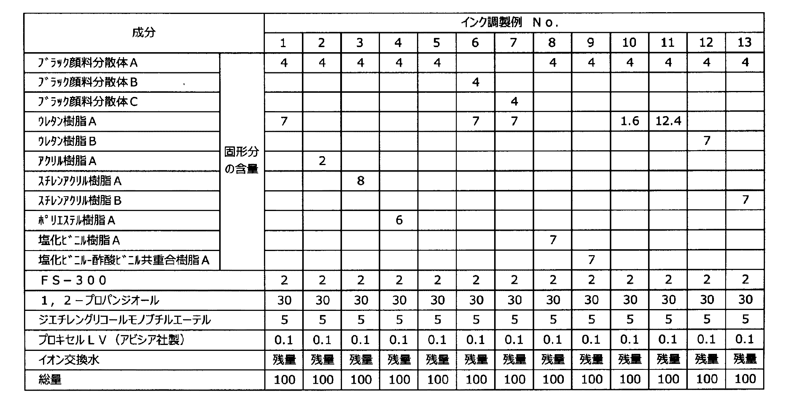
<ポリエステル樹脂エマルションAの調製>
先ず、あらかじめ225部の水に、ヒドロキシエチルセルロース(メトローズ60SH−50、信越化学社製)3.0部及びノニオン性乳化剤(エマルゲン1108、花王社製)を30部を固形分換算で溶解させて、乳化剤水溶液を調製した。
次いで、温度計、窒素導入管、撹拌機及び冷却管を備えた反応容器に、ポリ乳酸(バイロエコールBE−450、東洋紡製)150部をトルエン300部に溶解させ、上記乳化剤水溶液を加えて、45℃で30分間、攪拌混合して予備乳化を行った。
上記予備乳化物をマントンガウリン社製高圧乳化機によって300Kg/m2の圧力で乳化して微細乳化物を得た。
<Preparation of polyester resin emulsion A>
First, in 225 parts of water, 3.0 parts of hydroxyethyl cellulose (Metroses 60SH-50, manufactured by Shin-Etsu Chemical Co., Ltd.) and 30 parts of a nonionic emulsifier (Emulgen 1108, manufactured by Kao Corporation) were dissolved in terms of solid content. An aqueous emulsifier solution was prepared.
Next, in a reaction vessel equipped with a thermometer, a nitrogen introduction tube, a stirrer and a cooling tube, 150 parts of polylactic acid (Vylo Ecole BE-450, manufactured by Toyobo Co., Ltd.) is dissolved in 300 parts of toluene, and the aqueous emulsifier solution is added. Pre-emulsification was performed by stirring and mixing at 45 ° C. for 30 minutes.
The preliminary emulsion was emulsified with a high pressure emulsifier manufactured by Menton Gaurin at a pressure of 300 kg / m 2 to obtain a fine emulsion.
この微細乳化物を130mmHgの条件下で加熱減圧蒸留してトルエンを除去した後、固形分を調製し、固形分45%、pH2.4、粒子径0.32μmのポリエステルエマルションを得た後、25%アンモニア水にてpHを7.0に調整した。
このポリエステルエマルションに増粘剤(プライマルASE−60、ロームアンドハースジャパン社製)を0.6部添加し、固形分を40%に調整して、ポリエステル樹脂エマルションAを得た。
ポリエステル樹脂エマルションAのTgをDSC(リガク製Thermo plus EVO2/DSC)にて測定したところ0℃であった。
This fine emulsion was heated under reduced pressure under conditions of 130 mmHg to remove toluene, and then a solid content was prepared. After obtaining a polyester emulsion having a solid content of 45%, pH 2.4, and particle size of 0.32 μm, 25 The pH was adjusted to 7.0 with% ammonia water.
To this polyester emulsion, 0.6 part of a thickener (Primal ASE-60, manufactured by Rohm and Haas Japan) was added, and the solid content was adjusted to 40% to obtain a polyester resin emulsion A.
It was 0 degreeC when Tg of the polyester resin emulsion A was measured by DSC (Thermo plus Thermoplus EVO2 / DSC).
<液体組成物実施例1>
以下の配合で調合後、混合攪拌し、5μmのフィルター(ザルトリウス社製ミニザルト)で濾過して、液体組成物実施例1の液体組成物を得た。
1,2−プロパンジオール 10部
エマルゲンLS−106(花王社製ノニオン界面活性剤) 1部
酢酸カルシウム1水和物 1.76部
エチレン酢酸ビニル樹脂エマルションA(固形分として) 10部
プロキセルLV(アビシア製防腐剤) 0.1部
イオン交換水 77.14部
<Liquid composition example 1>
After mixing with the following formulation, the mixture was stirred and filtered through a 5 μm filter (Sartorius Mini-Salto) to obtain a liquid composition of Liquid Composition Example 1.
1,2-
<液体組成物実施例2〜43、液体組成物比較例1〜9>
表1−1〜表1−5に記載の処方で液体組成物実施例1と同様にして液体組成物実施例2〜43の液体組成物及び液体組成物比較例1〜9の液体組成物を調製した。
<Liquid Composition Examples 2 to 43, Liquid Composition Comparative Examples 1 to 9>
The liquid compositions of the liquid composition examples 2 to 43 and the liquid composition of the liquid composition comparative examples 1 to 9 were prepared in the same manner as the liquid composition example 1 with the formulations described in Table 1-1 to Table 1-5. Prepared.
ただし、上記に記載のない表中の樹脂には以下の市販品を使用した。
エチレン−酢酸ビニル樹脂B:
住化ケムテックス製スミカフレックス951HQ(Tg:−25℃)
エチレン−酢酸ビニル樹脂C:
住化ケムテックス製スミカフレックス408HQE(Tg:−30℃)
エチレン−酢酸ビニル−塩化ビニル共重合樹脂A:
住化ケムテックス製スミカフレックス808HQ(Tg:25℃)
エチレン−酢酸ビニル−塩化ビニル共重合樹脂B:
住化ケムテックス製スミカフレックス850HQ(Tg:30℃)
酢酸ビニル−アクリル樹脂A:
日信化学製ビニブラン1225(Tg:9℃)
スチレンブタジエン樹脂A:
日本エイアンドエル製ナルスターSR−130(Tg:−1℃)
また、表1−4及び表1−5中のアニオン樹脂及びカチオン樹脂は以下の通りである。
アニオン樹脂:三井化学製タケラックW−5661(ウレタン樹脂)
カチオン樹脂:ユニチカ製アローベースCB−1200(ポリオレフィン樹脂)
However, the following commercial products were used for the resins in the table not described above.
Ethylene-vinyl acetate resin B:
Sumikaflex 951HQ (Tg: -25 ° C) manufactured by Sumika Chemtex
Ethylene-vinyl acetate resin C:
Sumikaflex 408HQE (Tg: -30 ° C) manufactured by Sumika Chemtex
Ethylene-vinyl acetate-vinyl chloride copolymer resin A:
Sumika Flex 808HQ (Tg: 25 ° C) manufactured by Sumika Chemtex
Ethylene-vinyl acetate-vinyl chloride copolymer resin B:
Sumika Flex 850HQ (Tg: 30 ° C) manufactured by Sumika Chemtex
Vinyl acetate-acrylic resin A:
Nissin Chemical Vinibrand 1225 (Tg: 9 ° C)
Styrene butadiene resin A:
NALSTAR SR-130 manufactured by Nippon A & L (Tg: -1 ° C)
Moreover, the anion resin and cation resin in Table 1-4 and Table 1-5 are as follows.
Anionic resin: Takelac W-5661 (urethane resin) manufactured by Mitsui Chemicals
Cationic resin: Unitika Arrow Base CB-1200 (polyolefin resin)
<液体組成物の貯蔵安定性評価>
作製した液体組成物を密閉容器に入れ、80℃の恒温槽で2週間静置し、保管前後の粘度変化から液体組成物の貯蔵安定性を評価した。
判定は以下の基準にて行い、Bまでを許容範囲とした。
[評価基準]
A:粘度変化率が10%以内である。
B:粘度変化率が10%を超え、20%以内である。
C:粘度変化率が20%を超え、30%以内である。
D:粘度変化率が30%を超えているか、凝集物が発生している。
<Evaluation of storage stability of liquid composition>
The prepared liquid composition was put in a sealed container and allowed to stand in a constant temperature bath at 80 ° C. for 2 weeks, and the storage stability of the liquid composition was evaluated from the change in viscosity before and after storage.
The determination was made according to the following criteria, and the range up to B was set as an allowable range.
[Evaluation criteria]
A: Viscosity change rate is within 10%.
B: The viscosity change rate exceeds 10% and is within 20%.
C: Viscosity change rate exceeds 20% and is within 30%.
D: Viscosity change rate exceeds 30% or aggregates are generated.
<非印字部ラミネート評価>
作製した液体組成物をバーコーターNo.1にてOPPフィルム、PETフィルムに塗工し、80℃にて乾燥させた。
その上からドライラミネート用接着剤(主剤TM−320/硬化剤CAT−13B、東洋モートン社製)をバーコーターNo.4で塗工し、CPP(東洋紡社製パイレンP1128)を貼りあわせた後、40℃で48時間エージングした。
積層物を15mm幅にカットしたのち、T型剥離強度を測定し、以下の基準にて判定し、Bまでを許容範囲とした。
[評価基準]
A:5N/15mm以上の強度が得られる。
B:3N/15mm以上5N/15mm未満の強度が得られる。
C:1N/15mm以上3N/15mm未満の強度が得られる。
D:1N/15mm未満の強度しか得られない。
基材密着試験で使用した各種フィルムのメーカー名とグレードは以下の通りである。
OPP(二軸延伸ポリプロピレン):東洋紡製パイレンP2102
PET(ポリエチレンテレフタレート):東洋紡製エスペットE5100
尚、液体組成物比較例1は、酢酸カルシウム水溶液とアニオン樹脂が混ざった瞬間にゲル化して、フィルムに塗工することができず、非印字部ラミネート評価を行うことができなかった。液体組成物比較例7も同様に、ゲル化して、フィルムに塗工することができず、非印字部ラミネート評価を行うことができなかった。
<Non-printing part laminate evaluation>
The prepared liquid composition was subjected to bar coater no. 1 was coated on an OPP film and a PET film, and dried at 80 ° C.
On top of that, an adhesive for dry lamination (main agent TM-320 / curing agent CAT-13B, manufactured by Toyo Morton Co., Ltd.) was applied to bar coater No. After coating at 4 and bonding CPP (Pyrene P1128 manufactured by Toyobo Co., Ltd.), it was aged at 40 ° C. for 48 hours.
After the laminate was cut to a width of 15 mm, the T-type peel strength was measured and judged according to the following criteria, and the range up to B was set as an allowable range.
[Evaluation criteria]
A: A strength of 5 N / 15 mm or more is obtained.
B: A strength of 3 N / 15 mm or more and less than 5 N / 15 mm is obtained.
C: Strength of 1 N / 15 mm or more and less than 3 N / 15 mm is obtained.
D: Only strength of less than 1 N / 15 mm can be obtained.
Manufacturer names and grades of various films used in the substrate adhesion test are as follows.
OPP (biaxially oriented polypropylene): Toyobo Pyrene P2102
PET (polyethylene terephthalate): Toyobo Espet E5100
In addition, the liquid composition comparative example 1 gelled at the moment when the calcium acetate aqueous solution and the anion resin were mixed, and could not be applied to the film, and the non-printing portion laminate evaluation could not be performed. Similarly, the liquid composition comparative example 7 was gelled and could not be applied to the film, and the non-printing portion laminate evaluation could not be performed.
<顔料分散体の調製>
(ブラック顔料分散体Aの調製)
東海カーボン社製のカーボンブラック:シーストSP(SRF−LS)100gを、2.5N(規定)の次亜塩素酸ナトリウム溶液3000mLに添加し、温度60℃、速度300rpmで攪拌し、10時間反応させて酸化処理を行い、カーボンブラックの表面にカルボン酸基が付与された顔料を得た。
この反応液を濾過し、濾別したカーボンブラックを水酸化ナトリウム溶液で中和し、限外濾過を行った。
次いで、該顔料分散体とイオン交換水を用いて透析膜による限外濾過を行い、更に、超音波分散を行って、顔料固形分を20%に濃縮した体積平均粒径100nmのブラック顔料分散体Aを得た。
<Preparation of pigment dispersion>
(Preparation of black pigment dispersion A)
Carbon black manufactured by Tokai Carbon Co., Ltd .: 100 g of Seast SP (SRF-LS) is added to 3000 mL of 2.5N (standard) sodium hypochlorite solution, stirred at a temperature of 60 ° C. and a speed of 300 rpm, and allowed to react for 10 hours. Then, an oxidation treatment was performed to obtain a pigment having a carboxylic acid group added to the surface of carbon black.
The reaction solution was filtered, and the carbon black separated by filtration was neutralized with a sodium hydroxide solution and subjected to ultrafiltration.
Subsequently, ultrafiltration using a dialysis membrane is performed using the pigment dispersion and ion-exchanged water, and further, ultrasonic dispersion is performed to concentrate the pigment solid content to 20%. A was obtained.
(ブラック顔料分散体Bの調製)
ブラック分散体Aの調製において、使用するカーボンブラックをシーストTA(FT級)を使用する他は同様にして体積平均粒径125nmのブラック顔料分散体Bを得た。
(Preparation of black pigment dispersion B)
A black pigment dispersion B having a volume average particle diameter of 125 nm was obtained in the same manner as in the preparation of the black dispersion A, except that carbon black to be used was a seast TA (FT class).
(ブラック顔料分散体Cの調製)
ブラック分散体Aの調製において、使用するカーボンブラックをシーストKH(N39)を使用する他は同様にして体積平均粒径24nmのブラック顔料分散体Cを得た。
(Preparation of Black Pigment Dispersion C)
A black pigment dispersion C having a volume average particle size of 24 nm was obtained in the same manner as in the preparation of the black dispersion A, except that carbon black to be used was seast KH (N39).
(ブラック顔料分散体Dの調製)
ブラック分散体Aの調製において、使用するカーボンブラックを東海カーボン社製アクアブラック162を使用する他は同様にして体積平均粒径110nmのブラック顔料分散体Dを得た。
(Preparation of black pigment dispersion D)
In the preparation of the black dispersion A, a black pigment dispersion D having a volume average particle diameter of 110 nm was obtained in the same manner except that the carbon black used was Aqua Black 162 manufactured by Tokai Carbon Co., Ltd.
(ブラック顔料分散体Eの調製)
ブラック分散体Aの調製において、使用するカーボンブラックを三菱カーボンブラック社製汎用カラーRCF#30を使用する他は同様にして体積平均粒径30nmのブラック顔料分散体Eを得た。
(Preparation of black pigment dispersion E)
In the preparation of the black dispersion A, a black pigment dispersion E having a volume average particle diameter of 30 nm was obtained in the same manner except that the carbon black used was a general-purpose
(シアン顔料分散体Aの調製)
ブラック分散体Aの調製において、使用する色材をクラリアント社製Hostaperm Blue B4Gを使用する他は同様にして体積平均粒径62nmのシアン顔料分散体Aを得た。
(Preparation of cyan pigment dispersion A)
In the preparation of black dispersion A, cyan pigment dispersion A having a volume average particle diameter of 62 nm was obtained in the same manner except that Hostperm Blue B4G manufactured by Clariant was used as a coloring material.
(シアン顔料分散体Bの調製)
ブラック分散体Aの調製において、使用する色材を東洋インキ株式会社製銅フタロシアニン顔料(C.I.ピグメントブルー15:4、商品名:LX4033)にする他は同様にして体積平均粒径75nmのシアン顔料分散体Bを得た。
(Preparation of cyan pigment dispersion B)
In the preparation of the black dispersion A, a volume average particle diameter of 75 nm was similarly obtained except that a color material used was a copper phthalocyanine pigment (CI Pigment Blue 15: 4, trade name: LX4033) manufactured by Toyo Ink Co., Ltd. Cyan pigment dispersion B was obtained.
(マゼンタ顔料分散体Aの調製)
ブラック分散体Aの調製において、使用する色材をクラリアント社製Hostaperm Pink E02を使用する他は同様にして体積平均粒径87nmのマゼンタ顔料分散体Aを得た。
(Preparation of magenta pigment dispersion A)
A magenta pigment dispersion A having a volume average particle size of 87 nm was obtained in the same manner as in the preparation of the black dispersion A, except that the colorant used was Hosterperm Pink E02 manufactured by Clariant.
(マゼンタ顔料分散体Bの調製)
ブラック分散体Aの調製において、使用する色材をSun Chemical社製 Pigment Red 122にする他は同様にして体積平均粒径73nmのマゼンタ顔料分散体Bを得た。
(Preparation of magenta pigment dispersion B)
A magenta pigment dispersion B having a volume average particle size of 73 nm was obtained in the same manner as in the preparation of the black dispersion A, except that Pigment Red 122 manufactured by Sun Chemical was used as a coloring material.
(イエロー顔料分散体Aの調製)
ブラック分散体Aの調製において、使用する色材をクラリアント社製Hansa Brilliant Yellow 5GX03を使用する他は同様にして体積平均粒径75nmのイエロー顔料分散体Aを得た。
(Preparation of yellow pigment dispersion A)
In preparing the black dispersion A, a yellow pigment dispersion A having a volume average particle diameter of 75 nm was obtained in the same manner except that Hansa Brilliant Yellow 5GX03 manufactured by Clariant was used as a coloring material.
(イエロー顔料分散体Bの調製)
ブラック分散体Aの調製において、使用する色材を大日精化工業株式会社製イエロー顔料(ピグメントイエロー74、商品名:イエローNO.46)にする他は同様にして体積平均粒径82nmのイエロー顔料分散体Bを得た。
(Preparation of yellow pigment dispersion B)
In the preparation of the black dispersion A, a yellow pigment having a volume average particle diameter of 82 nm is similarly used except that a yellow pigment (Pigment Yellow 74, trade name: Yellow No. 46) manufactured by Dainichi Seika Kogyo Co., Ltd. is used as a color material. Dispersion B was obtained.
(白色顔料分散体Aの調製)
酸化チタンSTR−100W(堺化学工業株式会社製)25g、顔料分散剤TEGO Dispers651(エボニック社製)5g、水70gを混合し、ビーズミル(リサーチラボ、株式会社シンマルエンタープライゼス製)にて、0.3mmΦのジルコニアビーズを充填率60%、8m/sにて5分間分散し、体積平均粒径285nmの白色顔料分散体Aを得た。
(Preparation of white pigment dispersion A)
25 g of titanium oxide STR-100W (manufactured by Sakai Chemical Industry Co., Ltd.), 5 g of pigment dispersant TEGO Dispers651 (manufactured by Evonik Co., Ltd.), and 70 g of water were mixed, and 0 in a bead mill (Research Lab, manufactured by Shinmaru Enterprises Co., Ltd.) .3 mmΦ zirconia beads were dispersed at a filling rate of 60% and 8 m / s for 5 minutes to obtain a white pigment dispersion A having a volume average particle diameter of 285 nm.
(白色顔料分散体Bの調製)
白色顔料分散体Aの調製において、使用する酸化チタンをSTA−100Aを使用する他は同様にして体積平均粒径142nmの白色顔料分散体Bを得た。
(Preparation of white pigment dispersion B)
In the preparation of the white pigment dispersion A, a white pigment dispersion B having a volume average particle size of 142 nm was obtained in the same manner except that STA-100A was used as the titanium oxide.
(白色顔料分散体Cの調製)
白色顔料分散体Aの調製において、使用する酸化チタンをSTR−60Nを使用する他は同様にして体積平均粒径142nmの白色顔料分散体Cを得た。
(Preparation of white pigment dispersion C)
In the preparation of the white pigment dispersion A, a white pigment dispersion C having a volume average particle size of 142 nm was obtained in the same manner except that STR-60N was used as the titanium oxide to be used.
(白色顔料分散体D(中空樹脂粒子分散体)の調製)
中空樹脂粒子分散体は市販品「ローペイク ウルトラ」(スチレン・アクリル共重合体中空顔料エマルジョン、平均粒子径(D50)380nm、固形分濃度30.0%、ローム・アンド・ハース・ジャパン株式会社製)を用いた。
(Preparation of white pigment dispersion D (hollow resin particle dispersion))
The hollow resin particle dispersion is a commercially available product “Ropeque Ultra” (styrene / acryl copolymer hollow pigment emulsion, average particle size (D50) 380 nm, solid content concentration 30.0%, manufactured by Rohm and Haas Japan Co., Ltd.) Was used.
(白色顔料分散体E(無機中空粒子分散体)の調製)
ビーカー中でDISPERBYK−2008(BYK製アクリルコポリマー、有効成分60%)10.0gを高純水294.0gに溶解させ、日本精機製作所製エクセルオートホモジナイザーで5000rpm、30分間攪拌を行いながら、無機中空粒子(シリナックス(登録商標):日鉄鉱業製中空シリカ(一次粒子径80〜130nm、シリカ膜厚5〜15nm))50.0gを10分割して添加し混合させ、塊のない状態まで分散し、徐々に回転数を上げていき10000rpmで30分間攪拌を行った。
得られた顔料分散液を水冷しながら日本精機製作所製超音波ホモジナイザーUS−300T(チップφ26)にて200μAで1時間処理し、5μmのメンブランフィルター(セルロースアセテート膜)にて濾過を行って、無機中空粒子が14.1質量%の無機中空粒子分散体を得た。得られた分散体中の分散粒子について、粒度分布測定装置(マイクロトラックUPA、日機装株式会社製)で測定した平均粒子径(D50)は300nmであった。
(Preparation of white pigment dispersion E (inorganic hollow particle dispersion))
Dissolve 10.0 g of DISPERBYK-2008 (BYK acrylic copolymer, active ingredient 60%) in 294.0 g of high-purity water in a beaker and stir with an Excel auto homogenizer manufactured by Nippon Seiki Seisakusho at 5000 rpm for 30 minutes. Sirinax (registered trademark): 50.0 g of hollow silica (primary particle diameter of 80 to 130 nm, silica film thickness of 5 to 15 nm) manufactured by Nippon Steel & Mining Co., Ltd. was added in 10 portions, mixed, and dispersed to a state free of lumps The number of rotations was gradually increased, and stirring was performed at 10,000 rpm for 30 minutes.
The obtained pigment dispersion was treated with an ultrasonic homogenizer US-300T (Chip φ26) manufactured by Nippon Seiki Seisakusho for 1 hour while cooling with water, and filtered with a 5 μm membrane filter (cellulose acetate membrane). An inorganic hollow particle dispersion having 14.1% by mass of hollow particles was obtained. About the dispersed particles in the obtained dispersion, the average particle diameter (D50) measured by a particle size distribution measuring device (Microtrac UPA, manufactured by Nikkiso Co., Ltd.) was 300 nm.
<インクの調製方法>
インクの調製は、表2−1〜表2−4に記載したとおりの処方で混合攪拌し、非白色インクは0.2μmポリプロピレンフィルターにて、白色インクは0.5μmポリプロピレンフィルターにて濾過することにより作製した。
なお、界面活性剤は以下のものを使用した。
FS−300(DuPont社製フッ素系界面活性剤)
また、使用した樹脂は以下の通りである。
ウレタン樹脂A:
第一工業製薬製スーパーフレックス210(Tg:41℃)
ウレタン樹脂B:
第一工業製薬製スーパーフレックス420(Tg:−10℃)
アクリル樹脂A:
DIC製ボンコートCF−6140(Tg:12℃)
スチレンアクリル樹脂A:
日信化学製ビニブラン2685(Tg:50℃)
スチレンアクリル樹脂B:
DIC製ボンコートCG−8400(Tg:25℃)
ポリエステル樹脂A:
ユニチカ製エリーテルKA−5034(Tg:67℃)
塩化ビニル樹脂A:
日信化学製ビニブラン735(Tg:42℃)
塩化ビニル−酢酸ビニル共重合樹脂A:
日信化学製ソルバインTA3(Tg:65℃)
<Ink preparation method>
The ink is prepared by mixing and stirring according to the formulations described in Table 2-1 to Table 2-4. Filter non-white ink through a 0.2 μm polypropylene filter and white ink through a 0.5 μm polypropylene filter. It was produced by.
The following surfactants were used.
FS-300 (Fluorosurfactant manufactured by DuPont)
Moreover, the used resin is as follows.
Urethane resin A:
Dai-ichi Kogyo Seiyaku Superflex 210 (Tg: 41 ° C)
Urethane resin B:
Dai-ichi Kogyo Seiyaku Superflex 420 (Tg: -10 ° C)
Acrylic resin A:
DIC Boncoat CF-6140 (Tg: 12 ° C)
Styrene acrylic resin A:
Nissin Chemical's ViniBlan 2685 (Tg: 50 ° C)
Styrene acrylic resin B:
DIC Boncoat CG-8400 (Tg: 25 ° C)
Polyester resin A:
Unitika Elitel KA-5034 (Tg: 67 ° C)
Vinyl chloride resin A:
Nishin Chemical's ViniBran 735 (Tg: 42 ° C)
Vinyl chloride-vinyl acetate copolymer resin A:
Nissin Chemical's Solvein TA3 (Tg: 65 ° C)
作製したインク調製例1〜13のインクについて、以下の吐出安定性の評価を行った。
<吐出安定性評価>
作製したインクを図3で示した循環型の液滴吐出装置であるインクジェットプリンター(リコー製IPSiO GXe5500改造機)に充填し、ヘッドのキャッピングを外した状態で温度25℃、湿度15%RHで1時間放置した後、ノズルチェックパターンを印字し、不吐出、噴射乱れの有無を目視観察にて、以下の基準で判断した。結果を表3に示す。Bまでが許容範囲である。
A: 不吐出、噴射乱れが全く存在しない。
B: 若干の噴射乱れが認められる。
C: 不吐出が認められるノズルが存在する。
D: 不吐出が認められるノズルが大量に存在する。
The following ejection stability was evaluated for the prepared inks of Preparation Examples 1 to 13.
<Discharge stability evaluation>
The prepared ink is filled in an ink jet printer (Ricoh's IPSiO GXe5500 modified machine) which is a circulation type droplet discharge device shown in FIG. 3, and the temperature is 25 ° C. and humidity is 15% RH with the head capping removed. After being allowed to stand for a period of time, a nozzle check pattern was printed, and the presence or absence of ejection failure and ejection disturbance was determined by visual observation based on the following criteria. The results are shown in Table 3. The range up to B is an allowable range.
A: No ejection, no injection disturbance
B: Some injection disturbance is recognized.
C: There is a nozzle where ejection failure is observed.
D: There are a large number of nozzles where ejection failure is observed.
<インクセットの実施例>
(インクセット実施例1〜25)
インクセットは表4−1及び表4−2に示した液体組成物とインクの組み合わせ、および条件により、液体組成物の塗工およびインクの吐出を行い、印字部ラミネート強度評価、画像濃度評価、ネガ文字潰れ評価、耐擦過性評価、乾燥性評価を実施し、評価結果を表4−1及び表4−2に記載した。評価方法は以下に記載したとおりである。
<Example of ink set>
(Ink set examples 1 to 25)
The ink set is a combination of the liquid composition and the ink shown in Tables 4-1 and 4-2, and the conditions, and the liquid composition is applied and the ink is ejected. Negative character crushing evaluation, scratch resistance evaluation, and drying evaluation were performed, and the evaluation results are shown in Tables 4-1 and 4-2. The evaluation method is as described below.
(インクセット実施例26〜33)
インクセット実施例26では、インクセット実施例1と同じインクセットを用い、片面がコロナ処理されたOPPフィルム(東洋紡製パイレンP2102)のコロナ処理されていない面(印字面と逆側)を用いて評価を行った。
インクセット実施例27では、インクセット実施例1と同じインクセットを用い、通常80℃2分の乾燥条件のところ、室温で一晩放置したあとに評価を行った。
インクセット実施例28では、インクセット実施例1と同じインクセットを用い、液体組成物の塗工をバーコーターNo.1(巻線径0.025mm、付着量1.4g/m2)で行うところ、ロールコーターで付着量0.3g/m2になるように調整して評価を行った。
インクセット実施例29では、インクセット実施例1と同じインクセットを用い、液体組成物の塗工をバーコーターNo.1(巻線径0.025mm、付着量1.4g/m2)で実施していたところ巻線0.035mm(付着量2.3g/m2)で評価を行った。
インクセット実施例30では、インクセット実施例1と同じインクセットを用い、インクをプリンタで10g/m2となるよう吐出させているところを3g/m2となるように調製して評価を行った。
インクセット実施例31では、インクセット実施例1と同じインクセットを用い、インクをプリンタで10g/m2となるよう吐出させているところを15g/m2となるように調製して評価を行った。
インクセット実施例32では、インクセット実施例1と同じインクセットを用い、液体組成物の塗工をバーコーターNo.1(巻線径0.025mm、付着量1.4g/m2)で行うところ、ロールコーターで付着量0.4g/m2になるように速度を調整して評価を行った。
インクセット実施例33では、インクセット実施例1と同じインクセットを用い、液体組成物の塗工をバーコーターNo.1(巻線径0.025mm、付着量1.4g/m2)で実施していたところ巻線0.03mm(付着量2.0g/m2)で評価を行った。
実施例26〜33の評価結果は表4−3に記載した通りであった。
(Ink Set Examples 26 to 33)
Ink set example 26 uses the same ink set as ink set example 1, and uses the non-corona-treated surface (opposite to the print surface) of an OPP film (Toyobo's Pyrene P2102) with one side corona-treated. Evaluation was performed.
Ink set example 27 was evaluated using the same ink set as ink set example 1 and left at room temperature overnight under normal drying conditions of 80 ° C. for 2 minutes.
Ink set example 28 uses the same ink set as ink set example 1, and applied the liquid composition to a bar coater no. 1 (winding diameter: 0.025 mm, adhesion amount: 1.4 g / m 2 ), evaluation was performed by adjusting the adhesion amount to 0.3 g / m 2 with a roll coater.
Ink set example 29 uses the same ink set as ink set example 1 and applies the liquid composition to a bar coater no. 1 (winding wire diameter: 0.025 mm, coating weight 1.4 g / m 2) was evaluated in winding was not performed at 0.035 mm (deposition amount 2.3g / m 2).
Ink set example 30 uses the same ink set as ink set example 1, and the evaluation is performed by preparing a 3 g / m 2 area where ink is ejected to 10 g / m 2 with a printer. It was.
Ink set example 31 uses the same ink set as ink set example 1, and the evaluation is performed by preparing the ink ejected at 10 g / m 2 by the printer so as to be 15 g / m 2. It was.
Ink set example 32 uses the same ink set as ink set example 1, and applied the liquid composition to a bar coater no. 1 (winding diameter 0.025 mm, adhesion amount 1.4 g / m 2 ), the evaluation was performed by adjusting the speed so that the adhesion amount was 0.4 g / m 2 with a roll coater.
Ink set example 33 uses the same ink set as ink set example 1, and applied the liquid composition to a bar coater no. 1 (winding wire diameter: 0.025 mm, coating weight 1.4 g / m 2) was evaluated in winding was not performed at 0.03 mm (deposition amount 2.0g / m 2).
The evaluation results of Examples 26 to 33 were as described in Table 4-3.
(インクセット実施例34〜38)
インクセットは表4−4に示した液体組成物とインクの組み合わせ、および条件により、液体組成物の塗工およびインクの吐出を行い、印字部ラミネート強度評価、画像濃度評価、ネガ文字潰れ評価、耐擦過性評価、乾燥性評価を実施し、評価結果を表4−4に記載した。評価方法は以下に記載したとおりである。
(Ink set examples 34 to 38)
The ink set is a combination of the liquid composition and the ink shown in Table 4-4 and conditions, and the liquid composition is applied and the ink is ejected. The print portion laminate strength evaluation, the image density evaluation, the negative character crushing evaluation, Scratch resistance evaluation and dryness evaluation were performed, and the evaluation results are shown in Table 4-4. The evaluation method is as described below.
(インクセット実施例39〜46)
インクセットは表4−5に示した液体組成物とインクの組み合わせ、および条件により、液体組成物の塗工およびインクの吐出を行い、印字部ラミネート強度評価、画像濃度評価、ネガ文字潰れ評価、耐擦過性評価、乾燥性評価、色域評価、白インク沈降性評価を実施し、評価結果を表4−5に記載した。評価方法は以下に記載したとおりである。
インクセット実施例39では、インクセット実施例1の液体組成物およびブラックインク、インク調製例19の白色インクを用いて評価を行った。この際、インクの付与はブラックインク、白色インクの順に行った。
インクセット実施例40では、インクセット実施例1の液体組成物およびブラックインク、インク調製例20の白色インクを用いて評価を行った。この際、インクの付与はブラックインク、白色インクの順に行った。
インクセット実施例41では、インクセット実施例1の液体組成物およびブラックインク、インク調製例21の白色インクを用いて評価を行った。この際、インクの付与はブラックインク、白色インクの順に行った。
インクセット実施例42では、インクセット実施例1の液体組成物およびブラックインク、インク調製例22〜24のシアンインク、マゼンタインク、イエローインク、インク調製例19の白色インクを用いて色域評価を行った。この際、インクの付与は非白色インク、白色インクの順に行った。
インクセット実施例43では、インクセット実施例1の液体組成物およびブラックインク、インク調製例22〜24のシアンインク、マゼンタインク、イエローインクを用いて色域評価を行った。
インクセット実施例44では、インクセット実施例1の液体組成物およびブラックインク、インク調製例25の白色インクを用いて評価を行った。この際、インクの付与はブラックインク、白色インクの順に行った。
インクセット実施例45では、インクセット実施例1の液体組成物およびブラックインク、インク調製例26の白色インクを用いて評価を行った。この際、インクの付与はブラックインク、白色インクの順に行った。
インクセット実施例46では、インクセット実施例1の液体組成物およびブラックインク、インク調製例22〜24のシアンインク、マゼンタインク、イエローインク、インク調製例25の白色インクを用いて評価を行った。この際、インクの付与は非白色インク、白色インクの順に行った。
(Ink Set Examples 39 to 46)
The ink set is a combination of the liquid composition and the ink shown in Table 4-5, and the conditions, and the liquid composition is applied and the ink is ejected. The print portion laminate strength evaluation, the image density evaluation, the negative character crushing evaluation, Scratch resistance evaluation, drying evaluation, color gamut evaluation, and white ink sedimentation evaluation were carried out, and the evaluation results are shown in Table 4-5. The evaluation method is as described below.
Ink set example 39 was evaluated using the liquid composition and black ink of ink set example 1 and the white ink of ink preparation example 19. At this time, the ink was applied in the order of black ink and white ink.
Ink set example 40 was evaluated using the liquid composition and black ink of ink set example 1 and the white ink of ink preparation example 20. At this time, the ink was applied in the order of black ink and white ink.
Ink set example 41 was evaluated using the liquid composition and black ink of ink set example 1 and the white ink of ink preparation example 21. At this time, the ink was applied in the order of black ink and white ink.
Ink Set Example 42 performs color gamut evaluation using the liquid composition and black ink of Ink Set Example 1, the cyan ink, magenta ink, yellow ink, and white ink of Ink Preparation Example 19 of Ink Preparation Examples 22-24. went. At this time, ink was applied in the order of non-white ink and white ink.
In ink set example 43, color gamut evaluation was performed using the liquid composition and black ink of ink set example 1 and the cyan ink, magenta ink, and yellow ink of ink preparation examples 22-24.
Ink set example 44 was evaluated using the liquid composition and black ink of ink set example 1 and the white ink of ink preparation example 25. At this time, the ink was applied in the order of black ink and white ink.
Ink set example 45 was evaluated using the liquid composition and black ink of ink set example 1 and the white ink of ink preparation example 26. At this time, the ink was applied in the order of black ink and white ink.
Ink set example 46 was evaluated using the liquid composition and black ink of ink set example 1 and the cyan ink, magenta ink and yellow ink of ink preparation examples 22-24, and the white ink of ink preparation example 25. . At this time, ink was applied in the order of non-white ink and white ink.
(インクセット実施例47〜70)
インクセットは表4−6〜表4−7に示した液体組成物とインクの組み合わせ、および条件により、液体組成物の塗工およびインクの吐出を行い、印字部ラミネート強度評価、画像濃度評価、ネガ文字潰れ評価、耐擦過性評価、乾燥性評価を実施し、評価結果を表4−6〜表4−7に記載した。評価方法は以下に記載したとおりである。
(Ink Set Examples 47 to 70)
The ink set is a combination of the liquid composition and the ink shown in Table 4-6 to Table 4-7 and conditions, and the liquid composition is applied and the ink is ejected. Negative character crushing evaluation, scratch resistance evaluation, and drying evaluation were performed, and the evaluation results are shown in Tables 4-6 to 4-7. The evaluation method is as described below.
(インクセット実施例71〜76)
インクセット実施例71では、インクセット実施例10と同じインクセットを用い、片面がコロナ処理されたOPPフィルム(東洋紡製パイレンP2102)のコロナ処理されていない面(印字面と逆側)を用いて評価を行った。
インクセット実施例72では、インクセット実施例10と同じインクセットを用い、通常80℃2分の乾燥条件のところ、室温で一晩放置したあとに評価を行った。
インクセット実施例73では、インクセット実施例10と同じインクセットを用い、液体組成物の塗工をバーコーターNo.1(巻線径0.025mm、付着量1.4g/m2)で行うところ、ロールコーターで付着量0.3g/m2になるように調整して評価を行った。
インクセット実施例74では、インクセット実施例10と同じインクセットを用い、液体組成物の塗工をバーコーターNo.1(巻線径0.025mm、付着量1.4g/m2)で実施していたところ巻線0.035mm(付着量2.3g/m2)で評価を行った。
インクセット実施例75では、インクセット実施例10と同じインクセットを用い、インクをプリンタで10g/m2となるよう吐出させているところを3g/m2となるように調製して評価を行った。
インクセット実施例76では、インクセット実施例10と同じインクセットを用い、インクをプリンタで10g/m2となるよう吐出させているところを15g/m2となるように調製して評価を行った。
インクセット実施例71〜76の評価結果は表4−8に記載した通りであった。
(Ink Set Examples 71-76)
Ink set example 71 uses the same ink set as ink set example 10 and uses the non-corona-treated surface (opposite to the print surface) of an OPP film (Toyobo Pyrene P2102) with one side corona-treated. Evaluation was performed.
Ink set example 72 was evaluated using the same ink set as ink set example 10 and leaving it to stand overnight at room temperature under normal drying conditions of 80 ° C. for 2 minutes.
Ink set example 73 uses the same ink set as ink set example 10 and applies the liquid composition to a bar coater no. 1 (winding diameter: 0.025 mm, adhesion amount: 1.4 g / m 2 ), evaluation was performed by adjusting the adhesion amount to 0.3 g / m 2 with a roll coater.
Ink set example 74 uses the same ink set as ink set example 10 and applied the liquid composition to a bar coater no. 1 (winding wire diameter: 0.025 mm, coating weight 1.4 g / m 2) was evaluated in winding was not performed at 0.035 mm (deposition amount 2.3g / m 2).
Ink set example 75 uses the same ink set as ink set example 10, and prepared and evaluated 3 g / m 2 where the ink was ejected to 10 g / m 2 by the printer. It was.
Ink set embodiment 76 uses the same ink set as ink set
The evaluation results of Ink Set Examples 71 to 76 were as described in Table 4-8.
(インクセット実施例77〜81)
インクセットは表4−9に示した液体組成物とインクの組み合わせ、および条件により、液体組成物の塗工およびインクの吐出を行い、印字部ラミネート強度評価、画像濃度評価、ネガ文字潰れ評価、耐擦過性評価、乾燥性評価を実施し、評価結果を表4−9に記載した。評価方法は以下に記載したとおりである。
(Ink Set Examples 77 to 81)
The ink set is a combination of the liquid composition and the ink shown in Table 4-9 and conditions, and the liquid composition is applied and the ink is ejected. The print portion laminate strength evaluation, the image density evaluation, the negative character crushing evaluation, Scratch resistance evaluation and dryness evaluation were performed, and the evaluation results are shown in Table 4-9. The evaluation method is as described below.
(インクセット実施例82〜93)
インクセットは表4−10に示した液体組成物とインクの組み合わせ、および条件により、液体組成物の塗工およびインクの吐出を行い、印字部ラミネート強度評価、画像濃度評価、ネガ文字潰れ評価、耐擦過性評価、乾燥性評価を実施し、評価結果を表4−10に記載した。評価方法は以下に記載したとおりである。
(Ink set examples 82 to 93)
The ink set is a combination of the liquid composition and the ink shown in Table 4-10 and the conditions, and the liquid composition is applied and the ink is ejected. The print portion laminate strength evaluation, the image density evaluation, the negative character crushing evaluation, Scratch resistance evaluation and dryness evaluation were performed, and the evaluation results are shown in Table 4-10. The evaluation method is as described below.
<インクセット比較例1〜6>
インクセットの比較例には表4−11に示した通りの液体組成物とインクの組み合わせ、および条件により、液体組成物の塗工およびインクの吐出を行い、印字部ラミネート強度評価、画像濃度評価、ネガ文字潰れ評価、耐擦過性評価、乾燥性評価を行った。評価結果を表4−11に記載した。
<Ink set comparative examples 1 to 6>
In the comparative example of the ink set, the liquid composition was applied and the ink was ejected according to the combination and conditions of the liquid composition and the ink as shown in Table 4-11. Negative character crushing evaluation, scuff resistance evaluation, and dryness evaluation were performed. The evaluation results are shown in Table 4-11.
尚、液体組成物の塗工は、インクセット実施例26及び71以外では、OPPフィルム(東洋紡製パイレンP2102)のコロナ処理面に、更に表4−1〜表4−11に記載の表面改質処理を行い、表面改質処理を行った面に、表4−1〜表4−11に記載の条件で液体組成物を塗工した。インクセット実施例26及び71においては、OPPフィルム(東洋紡製パイレンP2102)のコロナ処理されていない面に、表4−3、表4−8に記載の条件で液体組成物を塗工した。 In addition to the ink set Examples 26 and 71, the liquid composition was coated on the corona-treated surface of the OPP film (Toyobo Pyrene P2102), and the surface modification described in Tables 4-1 to 4-11. The liquid composition was applied to the surface subjected to the treatment and subjected to the surface modification treatment under the conditions described in Tables 4-1 to 4-11. In Ink Set Examples 26 and 71, the liquid composition was applied to the surface of the OPP film (Toyobo Pyrene P2102) that was not subjected to corona treatment under the conditions described in Table 4-3 and Table 4-8.
<印字部ラミネート強度評価>
作製したインクをインクジェットプリンタ(株式会社リコー製IPSiO GXe5500)に充填し、予めバーコーターNo.1で液体組成物を塗工したのち乾燥させたOPPフィルム(東洋紡製パイレンP2102)に対して、表4−1〜表4−11に記載の条件で、インクを用いてベタ画像を印刷し、乾燥させた。ブラックインクおよびカラーインクを用いる場合は、混合ベタ画像を印刷した。
ベタ部にドライラミネート用接着剤(主剤TM−320/硬化剤CAT−13B、東洋モートン社製)をバーコーターで塗工し、CPP(東洋紡社製パイレンP1128)を貼りあわせた後、40℃で48時間エージングした。
積層物を15mm幅にカットしたのち、剥離強度を測定した。
Bまでが許容範囲である。
[評価基準]
A:5N/15mm以上の強度が得られる。
B:3N/15mm以上5N/15mm未満の強度が得られる。
C:1N/15mm以上3N/15mm未満の強度が得られる。
D:1N/15mm未満の強度しか得られない。
<Printing laminate strength evaluation>
The prepared ink was filled into an ink jet printer (IPSiO GXe5500 manufactured by Ricoh Co., Ltd.), and the bar coater No. A solid image was printed using ink under the conditions described in Tables 4-1 to 4-11 on the OPP film (Toyobo Pyrene P2102) dried after applying the liquid composition in Step 1. Dried. When black ink and color ink were used, a mixed solid image was printed.
After applying the adhesive for dry lamination (main agent TM-320 / curing agent CAT-13B, manufactured by Toyo Morton Co., Ltd.) to the solid part with a bar coater, and bonding CPP (Pyrene P1128 manufactured by Toyobo Co., Ltd.) at 40 ° C. Aged for 48 hours.
After the laminate was cut to a width of 15 mm, the peel strength was measured.
The range up to B is an allowable range.
[Evaluation criteria]
A: A strength of 5 N / 15 mm or more is obtained.
B: A strength of 3 N / 15 mm or more and less than 5 N / 15 mm is obtained.
C: Strength of 1 N / 15 mm or more and less than 3 N / 15 mm is obtained.
D: Only strength of less than 1 N / 15 mm can be obtained.
<画像濃度評価>
作製したインクをインクジェットプリンタ(株式会社リコー製IPSiO GXe5500)に充填し、予めバーコーターNo.1で液体組成物を塗工したのち乾燥させたOPPフィルム(東洋紡製パイレンP2102)に対して、1200×1200dpiで表4−1〜表4−11に記載の条件で、インク(ブラックインク)を用いて、ベタ印字を行った後、乾燥させてベタ部の濃度を測定し、以下の基準で判断した。
Bまでが許容範囲である。
[評価基準]
A:画像濃度2.0以上
B:画像濃度1.5以上2.0未満
C:画像濃度1.0以上1.5未満
D:画像濃度1.0未満
<Image density evaluation>
The prepared ink was filled into an ink jet printer (IPSiO GXe5500 manufactured by Ricoh Co., Ltd.), and the bar coater No. The ink (black ink) was applied to the OPP film (Toyobo Pyrene P2102) dried after coating the liquid composition in 1 under the conditions shown in Tables 4-1 to 4-11 at 1200 × 1200 dpi. Using this, after performing solid printing, it was dried and the density of the solid portion was measured, and judged according to the following criteria.
The range up to B is an allowable range.
[Evaluation criteria]
A: Image density 2.0 or more B: Image density 1.5 or more and less than 2.0 C: Image density 1.0 or more and less than 1.5 D: Image density 1.0 or less
<ネガ文字潰れ評価>
作製したインクをインクジェットプリンタ(株式会社リコー製IPSiO GXe5500)に充填し、予めバーコーターNo.1で液体組成物を塗工したのち乾燥させたOPPフィルム(東洋紡製パイレンP2102)に対して、表4−1〜表4−11に記載の条件で、インク(ブラックインク)を用いて、ゴシック体の白抜け文字チャートを印字し、乾燥した。
得られた画像の文字の可読性を肉眼で判断し、以下の基準で目視評価し、Bまでを許容範囲とした。
[評価基準]
S:2ptゴシック体が可読である。
A:2ptは非可読であるが、3ptは可読である。
B:3ptは非可読であるが、4ptは可読である。
C:4ptは非可読であるが、5ptは可読である。
D:5ptが非可読である。
また、カラーインクを用いたインクセット実施例42、43、46について、カラーインク単独でゴシック体の白抜け文字チャートを印字し、ブラックインクと同様に文字の可読性を評価した。評価結果は、ブラックインクの結果と同じであった。
<Negative character crush evaluation>
The prepared ink was filled into an ink jet printer (IPSiO GXe5500 manufactured by Ricoh Co., Ltd.), and the bar coater No. For the OPP film (Toyobo Pyrene P2102) which was dried after applying the liquid composition in No. 1, using ink (black ink) under the conditions shown in Tables 4-1 to 4-11, The body outline letter chart was printed and dried.
The readability of the characters of the obtained image was judged with the naked eye, visually evaluated according to the following criteria, and up to B was set as an allowable range.
[Evaluation criteria]
S: A 2pt Gothic body is readable.
A: 2pt is non-readable, but 3pt is readable.
B: 3pt is non-readable but 4pt is readable.
C: 4pt is non-readable, but 5pt is readable.
D: 5 pt is unreadable.
In addition, for ink setting Examples 42, 43, and 46 using color ink, a gothic blank character chart was printed with the color ink alone, and the character readability was evaluated in the same manner as the black ink. The evaluation result was the same as that of the black ink.
<耐擦過性評価>
作製したインクをインクジェットプリンタ(株式会社リコー製IPSiO GXe5500)に充填し、予めバーコーターNo.1で液体組成物を塗工したのち乾燥させたOPPフィルム(東洋紡製パイレンP2102)に対して、表4−1〜表4−11に記載の条件で、インクを用いて、ベタ画像を印刷した後、乾燥させた。ブラックインクおよびカラーインクを用いる場合は、混合ベタ画像を印刷した。
ベタ部を乾いた木綿(カナキン3号)で400gの加重をかけて擦過し、下記基準により耐擦過性を判定し、Bまでが許容範囲とした。
[評価基準]
A:100回以上擦っても画像が変化しない。
B:100回擦った段階で多少の傷が残るが画像濃度には影響しない。
C:100回擦過する間に画像濃度が低下してしまう。
D:50回以下の擦過にて画像濃度が低下してしまう。
<Abrasion resistance evaluation>
The prepared ink was filled into an ink jet printer (IPSiO GXe5500 manufactured by Ricoh Co., Ltd.), and the bar coater No. A solid image was printed on the OPP film (Toyobo Pyrene P2102 manufactured by Toyobo Co., Ltd.) after applying the liquid composition in 1 and using ink under the conditions described in Tables 4-1 to 4-11. After that, it was dried. When black ink and color ink were used, a mixed solid image was printed.
The solid part was rubbed with dry cotton (Kanakin No. 3) under a load of 400 g, and the rub resistance was judged according to the following criteria.
[Evaluation criteria]
A: The image does not change even after rubbing 100 times or more.
B: Some scratches remain after rubbing 100 times, but the image density is not affected.
C: The image density decreases while rubbing 100 times.
D: The image density is lowered by rubbing 50 times or less.
<乾燥性評価>
作製したインクをインクジェットプリンタ(株式会社リコー製IPSiO GXe5500)に充填し、予めバーコーターNo.1で液体組成物を塗工したのち乾燥させたOPPフィルム(東洋紡製パイレンP2102)に対して、表4−1〜表4−11に記載の条件で、インクを用いてベタ画像を印刷した後、25℃で所定の時間乾燥させた。ブラックインクおよびカラーインクを用いる場合は、混合ベタ画像を印刷した。
乾燥後のベタ部に濾紙を押し当て、濾紙へのインクの転写の具合から以下の基準により判定した。
A:25℃15分の乾燥条件で濾紙への転写がなくなる。
B:25℃30分の乾燥条件で濾紙への転写がなくなる。
C:25℃60分の乾燥条件で濾紙への転写がなくなる。
D:25℃60分の乾燥条件でも濾紙への転写がなくならない。
<Drying evaluation>
The prepared ink was filled into an ink jet printer (IPSiO GXe5500 manufactured by Ricoh Co., Ltd.), and the bar coater No. After printing a solid image using ink under the conditions described in Table 4-1 to Table 4-11 on the OPP film (Toyobo Pyrene P2102), which was dried after applying the liquid composition in Step 1. And dried at 25 ° C. for a predetermined time. When black ink and color ink were used, a mixed solid image was printed.
The filter paper was pressed against the solid portion after drying, and the determination was made according to the following criteria from the degree of ink transfer to the filter paper.
A: Transfer to filter paper is eliminated under drying conditions at 25 ° C. for 15 minutes.
B: Transfer to filter paper disappears under drying conditions at 25 ° C. for 30 minutes.
C: Transfer to filter paper disappears under drying conditions at 25 ° C. for 60 minutes.
D: Transfer to filter paper does not disappear even under drying conditions at 25 ° C. for 60 minutes.
<色域の評価>
インクセット実施例42、43および46のインクを、インクジェットプリンタ(株式会社リコー製IPSiO GXe5500)に充填し、予めバーコーターNo.1で液体組成物を塗工したのち乾燥させたOPP(東洋紡製パイレンP2102)に対して、1200×1200dpiで表4−5に記載の条件で、カラーチャート画像を印刷した後、乾燥させた。その後、測色器Xrite exact(Xrite社製)を用いてカラーチャート画像を測定し、各インクセットのL*値a*値b*値からガマット体積を算出し、以下の基準で判断した。Bまでが許容範囲である。
[評価基準]
A:ガマット値300,000以上
B:ガマット値200,000以上300,000未満
C:ガマット値200,000未満
<Evaluation of color gamut>
Ink set
[Evaluation criteria]
A: Gamut value of 300,000 or more B: Gamut value of 200,000 or more and less than 300,000 C: Gamut value of less than 200,000
<白インク沈降性評価>
調製したインクの中空粒子および顔料の沈降性は、タービスキャンMA2000(英弘精機株式会社製)を用いて評価した。
方法としては、評価インクを超音波分散処理(100W、40分)し、均一状態にしてから、ピペットを用いて装置専用のガラスセルに評価インクを5.5ml入れた。
セル内の評価インクの液面が安定した30分後に測定を行い、この時間を沈降性評価開始とした。
その後、23℃で静置し、120時間後まで測定を行い、沈降性評価開始を基準とした偏差表示にて、沈降性を確認した。沈降性を確認は、主に、上澄みの生成による後方散乱光の変化を、ピークの積算(相対値モード)で行い、以下の基準で評価した。
A:評価開始120時間後の相対変化が5%未満
B:評価開始120時間後の相対変化が5%以上10%未満
C:評価開始120時間後の相対変化が10%以上
<White ink sedimentation evaluation>
The sedimentation properties of the hollow particles and the pigment of the prepared ink were evaluated using Turbiscan MA2000 (manufactured by Eiko Seiki Co., Ltd.).
As a method, the evaluation ink was subjected to ultrasonic dispersion treatment (100 W, 40 minutes) to obtain a uniform state, and then 5.5 ml of the evaluation ink was put into a glass cell dedicated to the apparatus using a pipette.
Measurement was performed 30 minutes after the liquid level of the evaluation ink in the cell was stabilized, and this time was set as the start of sedimentation evaluation.
Then, it left still at 23 degreeC, it measured until 120 hours later, and the sedimentation property was confirmed by the deviation display on the basis of the sedimentation evaluation start. Confirmation of sedimentation was performed mainly by measuring the change in backscattered light due to the production of the supernatant by integrating the peaks (relative value mode) and evaluating the following criteria.
A: Relative change after 120 hours of evaluation is less than 5% B: Relative change after 120 hours of evaluation is 5% or more and less than 10% C: Relative change after 120 hours of evaluation is 10% or more
(図1、図2について)
400 画像形成装置
401 画像形成装置の外装
401c 装置本体のカバー
404 カートリッジホルダ
410 メインタンク
410k、410c、410m、410y ブラック(K)、シアン(C)、マゼンタ(M)、イエロー(Y)の各色用のメインタンク
411 インク収容部
413 インク排出口
414 収容容器ケース
420 機構部
434 吐出ヘッド
436 供給チューブ
(About Fig. 1 and Fig. 2)
400
(図3〜図8について)
1 ノズル板
2 流路板
3 振動板部材
4 ノズル
6 個別液室
6a、6b、6c、6d、6e 個別液室を構成する貫通溝部
7 流体抵抗部
7a 流体抵抗部を構成する貫通溝部
8 液導入部
8a、8b 液導入部を構成する貫通溝部
9 フィルタ部
10 共通液室
10A 下流側共通液室
10a 貫通溝部
10B 上流側共通液室
10b 溝部
11 圧電アクチュエータ
12 圧電部材
12A、12B 圧電素子
13 ベース部材
15 フレキシブル配線部材
20 共通液室部材
21 第1共通液室部材
22 第2共通液室部材
25a、25b 圧電アクチュエータ用貫通孔
30 振動領域
30a、30b 凸部
40 流路部材
41〜45 板状部材
50 循環共通液室
50a 溝部
51 流体抵抗部
51a 流体抵抗部を構成する貫通溝部
52、53 循環流路
52a、52b 循環流路を構成する貫通溝部
53a、53b、53c、53d 循環流路を構成する貫通溝部
71 供給ポート
71a 貫通穴
81 循環ポート
81a、81b 貫通穴
(About FIGS. 3 to 8)
DESCRIPTION OF SYMBOLS 1 Nozzle plate 2 Flow path plate 3
(図10について)
1 前処理液
2 膜厚制御ローラ
3 汲み上げローラ
4 付与ローラ
5 カウンタローラ
6 被印刷物
7 給紙ローラ
20 インクジェット記録ヘッド
(About Figure 10)
DESCRIPTION OF SYMBOLS 1 Pretreatment liquid 2 Film thickness control roller 3 Pumping-up
(図11について)
201 対向ローラ
202 圧力調整装置
203 記録媒体
204 前処理液収容容器
205 前処理液
206 攪拌・供給ローラ
207 移送ローラ
208 薄膜化ローラ
209 塗布ローラ
(About Figure 11)
201
Claims (16)
前記インクに含まれる熱可塑性樹脂粒子のガラス転移温度Tg2よりも低い請求項6〜10のいずれかに記載のインクセット。 The glass transition temperature Tg1 of the nonionic resin particles contained in the surface treatment liquid composition is
The ink set according to any one of claims 6 to 10, which is lower than a glass transition temperature Tg2 of thermoplastic resin particles contained in the ink.
Applications Claiming Priority (4)
| Application Number | Priority Date | Filing Date | Title |
|---|---|---|---|
| JP2016034407 | 2016-02-25 | ||
| JP2016034407 | 2016-02-25 | ||
| JP2016243438 | 2016-12-15 | ||
| JP2016243438 | 2016-12-15 |
Publications (2)
| Publication Number | Publication Date |
|---|---|
| JP2018094902A true JP2018094902A (en) | 2018-06-21 |
| JP7061277B2 JP7061277B2 (en) | 2022-04-28 |
Family
ID=58046525
Family Applications (1)
| Application Number | Title | Priority Date | Filing Date |
|---|---|---|---|
| JP2017031904A Active JP7061277B2 (en) | 2016-02-25 | 2017-02-23 | Liquid composition for surface treatment of printed matter, ink set, recording method, recording device |
Country Status (3)
| Country | Link |
|---|---|
| US (1) | US10259965B2 (en) |
| EP (1) | EP3211048B1 (en) |
| JP (1) | JP7061277B2 (en) |
Cited By (15)
| Publication number | Priority date | Publication date | Assignee | Title |
|---|---|---|---|---|
| WO2019188852A1 (en) * | 2018-03-30 | 2019-10-03 | 富士フイルム株式会社 | Pretreatment liquid, ink set, image recorded material, substrate for image recording, manufacturing method of substrate for image recording, and image recording method |
| JP2020059810A (en) * | 2018-10-11 | 2020-04-16 | コニカミノルタ株式会社 | Inkjet recording liquid set, production method of pretreatment liquid for inkjet recording, printed matter and inkjet recording method |
| JP2020104487A (en) * | 2018-12-28 | 2020-07-09 | セイコーエプソン株式会社 | Ink jet recording method, ink jet recording apparatus, and set of recording head and process liquid |
| JP2020157709A (en) * | 2019-03-28 | 2020-10-01 | セイコーエプソン株式会社 | Inkjet recording device and inkjet printing method |
| JP2020199717A (en) * | 2019-06-11 | 2020-12-17 | 株式会社リコー | Printing method and printing device |
| CN112123962A (en) * | 2019-06-24 | 2020-12-25 | 株式会社理光 | Liquid composition for surface treatment, printing method, and printing apparatus |
| US10906330B2 (en) | 2017-12-06 | 2021-02-02 | Ricoh Company, Ltd. | Image forming method, image forming device, and method of manufacturing printed matter |
| JP2021020394A (en) * | 2019-07-29 | 2021-02-18 | 株式会社リコー | Liquid composition, ink set, printing method, and printer |
| WO2021157310A1 (en) | 2020-02-04 | 2021-08-12 | コニカミノルタ株式会社 | Inkjet-recording method and image-recorded article |
| JP2021138823A (en) * | 2020-03-04 | 2021-09-16 | 株式会社リコー | Ink set and printing method |
| JPWO2021221069A1 (en) * | 2020-04-27 | 2021-11-04 | ||
| US11241887B2 (en) | 2019-02-28 | 2022-02-08 | Seiko Epson Corporation | Ink jet printing method and ink jet printing apparatus |
| WO2022190722A1 (en) | 2021-03-09 | 2022-09-15 | 富士フイルム株式会社 | Image recording method, image recorded material and inkset, and laminate and manufacturing method thereof |
| US11548294B2 (en) | 2020-10-20 | 2023-01-10 | Ricoh Company, Ltd. | Method of printing including applying a processing fluid and white ink to a substrate and device for such printing |
| WO2023047785A1 (en) | 2021-09-27 | 2023-03-30 | 富士フイルム株式会社 | Ink-jet recording method and method for producing laminate |
Families Citing this family (25)
| Publication number | Priority date | Publication date | Assignee | Title |
|---|---|---|---|---|
| US9925785B2 (en) * | 2015-09-30 | 2018-03-27 | Ricoh Company, Ltd. | Liquid discharge head, liquid discharge device, and liquid discharge apparatus |
| US10647129B2 (en) | 2017-03-16 | 2020-05-12 | Ricoh Company, Ltd. | Printing method and set of processing fluid and ink |
| WO2018181528A1 (en) * | 2017-03-31 | 2018-10-04 | 株式会社Dnpファインケミカル | Receptive solution, ink set containing said receptive solution and method for producing printed material using ink set |
| US10519330B2 (en) * | 2017-07-31 | 2019-12-31 | Ricoh Company, Ltd. | Ink, ink accommodating unit, recording method, recording device, and recorded matter |
| WO2019049135A1 (en) * | 2017-09-11 | 2019-03-14 | Kornit Digital Ltd. | Metallic inkjet compositions and processes for digitally printing metallic decorations on textile substrates |
| JP2019065087A (en) * | 2017-09-28 | 2019-04-25 | セイコーエプソン株式会社 | Reaction liquid and recording method |
| US11098216B2 (en) * | 2017-09-28 | 2021-08-24 | Ricoh Company, Ltd. | Image forming method, image forming apparatus, and method for manufacturing printed matter |
| WO2019083514A1 (en) | 2017-10-24 | 2019-05-02 | Hewlett-Packard Development Company, L.P. | Fusing agent including a metal bis(dithiolene) salt |
| JP7073804B2 (en) * | 2018-03-14 | 2022-05-24 | セイコーエプソン株式会社 | Ink set and recording method using the ink set |
| JP7107024B2 (en) | 2018-06-26 | 2022-07-27 | 株式会社リコー | Image forming method and image forming apparatus |
| US20210238436A1 (en) * | 2018-08-30 | 2021-08-05 | Hewlett-Packard Development Company, L.P. | Fluid set for textile printing |
| JP2020050705A (en) | 2018-09-25 | 2020-04-02 | 株式会社リコー | Ink, inkjet printing method, and printed matter |
| US11603478B2 (en) | 2019-01-25 | 2023-03-14 | Ricoh Company, Ltd. | Ink, method of manufacturing ink, printing method, and printing device |
| JP2023507767A (en) * | 2019-12-18 | 2023-02-27 | デュポン エレクトロニクス インコーポレイテッド | Inkjet ink and primer fluid set |
| EP4077555A1 (en) * | 2019-12-18 | 2022-10-26 | DuPont Electronics, Inc. | Inkjet ink and primer fluid set |
| JP7524636B2 (en) | 2019-12-18 | 2024-07-30 | 株式会社リコー | Pretreatment liquid and ink set, inkjet printing apparatus and inkjet printing method |
| JP7494503B2 (en) | 2020-03-17 | 2024-06-04 | 株式会社リコー | Ink, ink container, printing device, and printing method |
| WO2022003336A1 (en) * | 2020-06-30 | 2022-01-06 | Sun Chemical Corporation | Lamination primers and inks for aqueous inkjet printing |
| JP2022023352A (en) * | 2020-07-27 | 2022-02-08 | 株式会社リコー | Processing liquid, set of processing liquid and ink, printing method, and printer |
| EP3981605A3 (en) * | 2020-08-18 | 2022-05-04 | Ricoh Company, Ltd. | Printing method, printing apparatus, and printed matter |
| EP4214061A1 (en) * | 2020-09-16 | 2023-07-26 | Ricoh Company, Ltd. | Printing method, printing apparatus, and printed matter |
| US11845875B2 (en) | 2020-11-30 | 2023-12-19 | Ricoh Company, Ltd. | Glittery ink and image forming device |
| US20220169034A1 (en) * | 2020-11-30 | 2022-06-02 | Ricoh Company, Ltd. | Processing fluid, method of producing printed matter, and device of producing printed matter |
| JP2022101991A (en) * | 2020-12-25 | 2022-07-07 | セイコーエプソン株式会社 | Recording method and ink-jet recording device |
| JP7272496B1 (en) * | 2022-06-01 | 2023-05-12 | 東洋インキScホールディングス株式会社 | Aqueous pretreatment liquid, ink set, printed matter, and separation method |
Citations (18)
| Publication number | Priority date | Publication date | Assignee | Title |
|---|---|---|---|---|
| JPH11269783A (en) * | 1998-03-20 | 1999-10-05 | Suminoe Textile Co Ltd | Fabric for ink-jet dyeing nd dyeing |
| US20040255820A1 (en) * | 2003-06-17 | 2004-12-23 | J.M. Huber Corporation | Pigment for use in inkjet recording medium coatings and methods |
| JP2005074655A (en) * | 2003-08-28 | 2005-03-24 | Seiko Epson Corp | Reaction liquid, ink set, and inkjet recording method |
| JP2007261206A (en) * | 2006-03-29 | 2007-10-11 | Fujifilm Corp | Ink set for inkjet recording, image recording method and device |
| JP2009096175A (en) * | 2007-09-25 | 2009-05-07 | Fujifilm Corp | Image forming method and image forming apparatus |
| WO2009084600A1 (en) * | 2007-12-28 | 2009-07-09 | Sakata Inx Corp. | Treatment solution for ink jet textile printing, ink jet textile printing method, and product printed by ink jet textile printing |
| JP2009233867A (en) * | 2008-03-25 | 2009-10-15 | Fujifilm Corp | Inkjet recording method and recorded matter |
| JP2010503779A (en) * | 2006-09-15 | 2010-02-04 | イー・アイ・デュポン・ドウ・ヌムール・アンド・カンパニー | Fabric pre-treatment for inkjet printing |
| JP2010194998A (en) * | 2009-02-27 | 2010-09-09 | Konica Minolta Holdings Inc | Ink-jet ink set and ink-jet recording image forming method |
| JP2011521085A (en) * | 2008-05-22 | 2011-07-21 | イー・アイ・デュポン・ドウ・ヌムール・アンド・カンパニー | Fixing ink used with inkjet ink |
| JP2013018219A (en) * | 2011-07-12 | 2013-01-31 | Ricoh Co Ltd | Image forming method and image forming apparatus |
| JP2013545646A (en) * | 2010-12-15 | 2013-12-26 | ニューページ コーポレーション | Inkjet printing recording medium |
| JP2015071289A (en) * | 2013-09-05 | 2015-04-16 | 株式会社リコー | Droplet discharge head and image forming apparatus |
| JP2015136887A (en) * | 2014-01-23 | 2015-07-30 | 株式会社リコー | Liquid droplet discharge device, deairing method, nozzle cleaning method and image forming device |
| JP2015182403A (en) * | 2014-03-26 | 2015-10-22 | 三菱製紙株式会社 | Inkjet recording paper sheet |
| JP2015187254A (en) * | 2014-03-13 | 2015-10-29 | 株式会社リコー | Ink, inkjet recording method, and recorded matter |
| JP2016006150A (en) * | 2013-11-19 | 2016-01-14 | 株式会社リコー | Inkjet ink, ink cartridge, and inkjet recording device |
| JP2017517640A (en) * | 2014-02-28 | 2017-06-29 | ルブリゾル アドバンスド マテリアルズ, インコーポレイテッド | Fabric pretreatment for digital printing |
Family Cites Families (10)
| Publication number | Priority date | Publication date | Assignee | Title |
|---|---|---|---|---|
| JP4019505B2 (en) | 1998-06-08 | 2007-12-12 | 富士ゼロックス株式会社 | Recording material and image forming method |
| JP4240375B2 (en) | 2003-07-31 | 2009-03-18 | セイコーエプソン株式会社 | Liquid composition |
| JP5003282B2 (en) | 2007-05-23 | 2012-08-15 | 富士ゼロックス株式会社 | Droplet discharge head and image forming apparatus |
| JP2009056615A (en) * | 2007-08-30 | 2009-03-19 | Ricoh Co Ltd | Ink-jet recording method |
| US8216666B2 (en) * | 2008-02-29 | 2012-07-10 | The Procter & Gamble Company | Substrates having improved crockfastness |
| JP5691625B2 (en) * | 2010-02-26 | 2015-04-01 | 株式会社リコー | Inkjet treatment liquid, inkjet recording apparatus, inkjet recording method, and image formed product |
| JP2013064074A (en) * | 2011-09-16 | 2013-04-11 | Fujifilm Corp | Ink composition, ink set and image forming method |
| JP6388249B2 (en) | 2013-08-21 | 2018-09-12 | セイコーエプソン株式会社 | Ink set and recording method using the same |
| JP6332604B2 (en) * | 2014-02-27 | 2018-05-30 | セイコーエプソン株式会社 | Pretreatment liquid for inkjet printing and printing method |
| JP6394854B2 (en) * | 2014-03-27 | 2018-09-26 | セイコーエプソン株式会社 | Treatment liquid, recording method |
-
2017
- 2017-02-13 EP EP17155908.1A patent/EP3211048B1/en active Active
- 2017-02-17 US US15/436,256 patent/US10259965B2/en active Active
- 2017-02-23 JP JP2017031904A patent/JP7061277B2/en active Active
Patent Citations (18)
| Publication number | Priority date | Publication date | Assignee | Title |
|---|---|---|---|---|
| JPH11269783A (en) * | 1998-03-20 | 1999-10-05 | Suminoe Textile Co Ltd | Fabric for ink-jet dyeing nd dyeing |
| US20040255820A1 (en) * | 2003-06-17 | 2004-12-23 | J.M. Huber Corporation | Pigment for use in inkjet recording medium coatings and methods |
| JP2005074655A (en) * | 2003-08-28 | 2005-03-24 | Seiko Epson Corp | Reaction liquid, ink set, and inkjet recording method |
| JP2007261206A (en) * | 2006-03-29 | 2007-10-11 | Fujifilm Corp | Ink set for inkjet recording, image recording method and device |
| JP2010503779A (en) * | 2006-09-15 | 2010-02-04 | イー・アイ・デュポン・ドウ・ヌムール・アンド・カンパニー | Fabric pre-treatment for inkjet printing |
| JP2009096175A (en) * | 2007-09-25 | 2009-05-07 | Fujifilm Corp | Image forming method and image forming apparatus |
| WO2009084600A1 (en) * | 2007-12-28 | 2009-07-09 | Sakata Inx Corp. | Treatment solution for ink jet textile printing, ink jet textile printing method, and product printed by ink jet textile printing |
| JP2009233867A (en) * | 2008-03-25 | 2009-10-15 | Fujifilm Corp | Inkjet recording method and recorded matter |
| JP2011521085A (en) * | 2008-05-22 | 2011-07-21 | イー・アイ・デュポン・ドウ・ヌムール・アンド・カンパニー | Fixing ink used with inkjet ink |
| JP2010194998A (en) * | 2009-02-27 | 2010-09-09 | Konica Minolta Holdings Inc | Ink-jet ink set and ink-jet recording image forming method |
| JP2013545646A (en) * | 2010-12-15 | 2013-12-26 | ニューページ コーポレーション | Inkjet printing recording medium |
| JP2013018219A (en) * | 2011-07-12 | 2013-01-31 | Ricoh Co Ltd | Image forming method and image forming apparatus |
| JP2015071289A (en) * | 2013-09-05 | 2015-04-16 | 株式会社リコー | Droplet discharge head and image forming apparatus |
| JP2016006150A (en) * | 2013-11-19 | 2016-01-14 | 株式会社リコー | Inkjet ink, ink cartridge, and inkjet recording device |
| JP2015136887A (en) * | 2014-01-23 | 2015-07-30 | 株式会社リコー | Liquid droplet discharge device, deairing method, nozzle cleaning method and image forming device |
| JP2017517640A (en) * | 2014-02-28 | 2017-06-29 | ルブリゾル アドバンスド マテリアルズ, インコーポレイテッド | Fabric pretreatment for digital printing |
| JP2015187254A (en) * | 2014-03-13 | 2015-10-29 | 株式会社リコー | Ink, inkjet recording method, and recorded matter |
| JP2015182403A (en) * | 2014-03-26 | 2015-10-22 | 三菱製紙株式会社 | Inkjet recording paper sheet |
Cited By (25)
| Publication number | Priority date | Publication date | Assignee | Title |
|---|---|---|---|---|
| US10906330B2 (en) | 2017-12-06 | 2021-02-02 | Ricoh Company, Ltd. | Image forming method, image forming device, and method of manufacturing printed matter |
| US11807023B2 (en) | 2018-03-30 | 2023-11-07 | Fujifilm Corporation | Pretreatment liquid, ink set, image recorded material, base material for image recording, method of producing base material for image recording, and image recording method |
| WO2019188852A1 (en) * | 2018-03-30 | 2019-10-03 | 富士フイルム株式会社 | Pretreatment liquid, ink set, image recorded material, substrate for image recording, manufacturing method of substrate for image recording, and image recording method |
| JP2020059810A (en) * | 2018-10-11 | 2020-04-16 | コニカミノルタ株式会社 | Inkjet recording liquid set, production method of pretreatment liquid for inkjet recording, printed matter and inkjet recording method |
| JP7192376B2 (en) | 2018-10-11 | 2022-12-20 | コニカミノルタ株式会社 | Inkjet recording liquid set, method for producing pretreatment liquid for inkjet recording, printed matter and inkjet recording method |
| US11466172B2 (en) | 2018-10-11 | 2022-10-11 | Konica Minolta, Inc. | Ink-jet recording liquid set, preparation method of pretreatment liquid for ink-jet recording, printed matter, and ink-jet recording method |
| JP2020104487A (en) * | 2018-12-28 | 2020-07-09 | セイコーエプソン株式会社 | Ink jet recording method, ink jet recording apparatus, and set of recording head and process liquid |
| JP7275577B2 (en) | 2018-12-28 | 2023-05-18 | セイコーエプソン株式会社 | Inkjet recording method and inkjet recording apparatus |
| US11241887B2 (en) | 2019-02-28 | 2022-02-08 | Seiko Epson Corporation | Ink jet printing method and ink jet printing apparatus |
| JP2020157709A (en) * | 2019-03-28 | 2020-10-01 | セイコーエプソン株式会社 | Inkjet recording device and inkjet printing method |
| JP2020199717A (en) * | 2019-06-11 | 2020-12-17 | 株式会社リコー | Printing method and printing device |
| JP7258285B2 (en) | 2019-06-11 | 2023-04-17 | 株式会社リコー | Printing method and printing device |
| EP3756902A1 (en) | 2019-06-24 | 2020-12-30 | Ricoh Company, Ltd. | Liquid composition for surface treatment, printing method, and printing device |
| JP2021000790A (en) * | 2019-06-24 | 2021-01-07 | 株式会社リコー | Surface treatment liquid composition, printing method and printing apparatus |
| CN112123962A (en) * | 2019-06-24 | 2020-12-25 | 株式会社理光 | Liquid composition for surface treatment, printing method, and printing apparatus |
| JP2021020394A (en) * | 2019-07-29 | 2021-02-18 | 株式会社リコー | Liquid composition, ink set, printing method, and printer |
| WO2021157310A1 (en) | 2020-02-04 | 2021-08-12 | コニカミノルタ株式会社 | Inkjet-recording method and image-recorded article |
| JP2021138823A (en) * | 2020-03-04 | 2021-09-16 | 株式会社リコー | Ink set and printing method |
| WO2021221069A1 (en) * | 2020-04-27 | 2021-11-04 | 富士フイルム株式会社 | Image recording method |
| JPWO2021221069A1 (en) * | 2020-04-27 | 2021-11-04 | ||
| CN115461227A (en) * | 2020-04-27 | 2022-12-09 | 富士胶片株式会社 | Image recording method |
| JP7459236B2 (en) | 2020-04-27 | 2024-04-01 | 富士フイルム株式会社 | Image recording method |
| US11548294B2 (en) | 2020-10-20 | 2023-01-10 | Ricoh Company, Ltd. | Method of printing including applying a processing fluid and white ink to a substrate and device for such printing |
| WO2022190722A1 (en) | 2021-03-09 | 2022-09-15 | 富士フイルム株式会社 | Image recording method, image recorded material and inkset, and laminate and manufacturing method thereof |
| WO2023047785A1 (en) | 2021-09-27 | 2023-03-30 | 富士フイルム株式会社 | Ink-jet recording method and method for producing laminate |
Also Published As
| Publication number | Publication date |
|---|---|
| JP7061277B2 (en) | 2022-04-28 |
| US10259965B2 (en) | 2019-04-16 |
| US20170247561A1 (en) | 2017-08-31 |
| EP3211048A1 (en) | 2017-08-30 |
| EP3211048B1 (en) | 2020-07-08 |
Similar Documents
| Publication | Publication Date | Title |
|---|---|---|
| JP7061277B2 (en) | Liquid composition for surface treatment of printed matter, ink set, recording method, recording device | |
| JP6922189B2 (en) | Ink ejection device and ink ejection method | |
| JP7131174B2 (en) | IMAGE FORMING METHOD, IMAGE FORMING APPARATUS, AND PRINTED MATERIAL MANUFACTURING METHOD | |
| US11098216B2 (en) | Image forming method, image forming apparatus, and method for manufacturing printed matter | |
| JP7114879B2 (en) | Cleaning liquid, storage container, inkjet printing method, inkjet printing apparatus, and set of ink and cleaning liquid | |
| JP2021020394A (en) | Liquid composition, ink set, printing method, and printer | |
| JP7258285B2 (en) | Printing method and printing device | |
| JP7107024B2 (en) | Image forming method and image forming apparatus | |
| JP2018154118A (en) | Printing method, set of treatment liquid and ink, and printing device | |
| JP2023017918A (en) | Liquid discharge device and liquid discharge method | |
| JP6710981B2 (en) | Printing method, printing device, and printing set of pretreatment liquid and ink | |
| JP6965628B2 (en) | Image forming method, image forming apparatus and printed matter manufacturing method | |
| CN112123962A (en) | Liquid composition for surface treatment, printing method, and printing apparatus | |
| JP6941269B2 (en) | Ink ejection device and ink ejection method | |
| JP2017101232A (en) | Ink, recording method, recording device and ink accommodating container | |
| JP6866734B2 (en) | Printing method | |
| JP6228615B2 (en) | Heat-sealable recording sheet | |
| US20220024220A1 (en) | Processing liquid, set, method of printing, and printing device | |
| JP2021042273A (en) | Ink set, set, printing method and printing device | |
| JP7180476B2 (en) | ink | |
| JP6596999B2 (en) | Ink set, ink cartridge, ink jet recording apparatus, and ink jet recording method | |
| JP7137123B2 (en) | ink set, white ink, recording method, ink ejection device | |
| JP2018154696A (en) | Aqueous latex liquid composition, and apparatus for discharging liquid | |
| JP2006291174A (en) | Water-based ink, ink cartridge, ink recorded product, ink jet recording device and ink jet recording method | |
| CN115667431A (en) | White ink, non-white ink, ink set, printing method, and printing apparatus |
Legal Events
| Date | Code | Title | Description |
|---|---|---|---|
| A621 | Written request for application examination |
Free format text: JAPANESE INTERMEDIATE CODE: A621 Effective date: 20191216 |
|
| A977 | Report on retrieval |
Free format text: JAPANESE INTERMEDIATE CODE: A971007 Effective date: 20200730 |
|
| A131 | Notification of reasons for refusal |
Free format text: JAPANESE INTERMEDIATE CODE: A131 Effective date: 20210121 |
|
| A521 | Request for written amendment filed |
Free format text: JAPANESE INTERMEDIATE CODE: A523 Effective date: 20210301 |
|
| A131 | Notification of reasons for refusal |
Free format text: JAPANESE INTERMEDIATE CODE: A131 Effective date: 20210827 |
|
| A521 | Request for written amendment filed |
Free format text: JAPANESE INTERMEDIATE CODE: A523 Effective date: 20211019 |
|
| TRDD | Decision of grant or rejection written | ||
| A01 | Written decision to grant a patent or to grant a registration (utility model) |
Free format text: JAPANESE INTERMEDIATE CODE: A01 Effective date: 20220318 |
|
| A61 | First payment of annual fees (during grant procedure) |
Free format text: JAPANESE INTERMEDIATE CODE: A61 Effective date: 20220331 |
|
| R151 | Written notification of patent or utility model registration |
Ref document number: 7061277 Country of ref document: JP Free format text: JAPANESE INTERMEDIATE CODE: R151 |