JP2018093733A - Shellfish hanging pin removal apparatus - Google Patents
Shellfish hanging pin removal apparatus Download PDFInfo
- Publication number
- JP2018093733A JP2018093733A JP2016237945A JP2016237945A JP2018093733A JP 2018093733 A JP2018093733 A JP 2018093733A JP 2016237945 A JP2016237945 A JP 2016237945A JP 2016237945 A JP2016237945 A JP 2016237945A JP 2018093733 A JP2018093733 A JP 2018093733A
- Authority
- JP
- Japan
- Prior art keywords
- pin
- shell
- protrusions
- rotating body
- rotating
- Prior art date
- Legal status (The legal status is an assumption and is not a legal conclusion. Google has not performed a legal analysis and makes no representation as to the accuracy of the status listed.)
- Granted
Links
- 235000015170 shellfish Nutrition 0.000 title claims abstract description 10
- 239000000725 suspension Substances 0.000 claims description 33
- 238000003825 pressing Methods 0.000 claims description 20
- 230000002093 peripheral effect Effects 0.000 claims description 7
- 230000001681 protective effect Effects 0.000 claims description 4
- 230000001154 acute effect Effects 0.000 claims description 3
- 125000006850 spacer group Chemical group 0.000 claims description 2
- 238000009360 aquaculture Methods 0.000 abstract description 7
- 244000144974 aquaculture Species 0.000 abstract description 7
- 235000020637 scallop Nutrition 0.000 description 14
- 241000237509 Patinopecten sp. Species 0.000 description 8
- 238000000034 method Methods 0.000 description 7
- 241000237503 Pectinidae Species 0.000 description 6
- 239000011347 resin Substances 0.000 description 3
- 229920005989 resin Polymers 0.000 description 3
- 238000004140 cleaning Methods 0.000 description 2
- 238000007796 conventional method Methods 0.000 description 2
- 238000010586 diagram Methods 0.000 description 2
- 238000003466 welding Methods 0.000 description 2
- 238000005520 cutting process Methods 0.000 description 1
- 238000007599 discharging Methods 0.000 description 1
- 238000001035 drying Methods 0.000 description 1
- 238000005516 engineering process Methods 0.000 description 1
- 238000010030 laminating Methods 0.000 description 1
- 238000003698 laser cutting Methods 0.000 description 1
- 230000001012 protector Effects 0.000 description 1
- 238000004114 suspension culture Methods 0.000 description 1
- 238000011144 upstream manufacturing Methods 0.000 description 1
- 238000004804 winding Methods 0.000 description 1
Images


Classifications
-
- Y—GENERAL TAGGING OF NEW TECHNOLOGICAL DEVELOPMENTS; GENERAL TAGGING OF CROSS-SECTIONAL TECHNOLOGIES SPANNING OVER SEVERAL SECTIONS OF THE IPC; TECHNICAL SUBJECTS COVERED BY FORMER USPC CROSS-REFERENCE ART COLLECTIONS [XRACs] AND DIGESTS
- Y02—TECHNOLOGIES OR APPLICATIONS FOR MITIGATION OR ADAPTATION AGAINST CLIMATE CHANGE
- Y02A—TECHNOLOGIES FOR ADAPTATION TO CLIMATE CHANGE
- Y02A40/00—Adaptation technologies in agriculture, forestry, livestock or agroalimentary production
- Y02A40/80—Adaptation technologies in agriculture, forestry, livestock or agroalimentary production in fisheries management
- Y02A40/81—Aquaculture, e.g. of fish
Abstract
Description
本発明は、ロープに差し込まれている貝吊り用ピンをロープから除去するための貝吊り用ピン除去装置に関する。 The present invention relates to a shell suspending pin removing device for removing a shell suspending pin inserted into a rope from the rope.
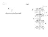
ホタテ貝の耳吊り養殖では、図1(b)に示されるように、長さ10〜15mの養殖ロープに、長さ方向に沿って多数のホタテ貝が吊るされる。養殖ロープにホタテ貝を吊るすために、例えば図1(a)に示されるような形状の貝吊り用ピン(一般に、アゲピンと呼ばれている)が用いられる(例えば、特許文献1)。貝吊り用ピンは、通常、両端及び中央付近に、該ピンの長さ方向中央部に向かって斜めに立ち上がるくさび状の係止部を有する。両端の係止部は、貝がピンから抜けるのを防止し、中央の係止部は、ロープに差し込まれたピンが偏るのを防止する。 In scallop ear suspension culture, as shown in FIG. 1 (b), a large number of scallops are suspended along a length direction on a culture rope having a length of 10 to 15 m. In order to suspend scallops on an aquaculture rope, for example, a pin for suspending a shell (generally called an age pin) having a shape as shown in FIG. 1A is used (for example, Patent Document 1). The shell hanging pin usually has a wedge-shaped locking portion that rises obliquely toward the center in the length direction of the pin at both ends and near the center. The locking portions at both ends prevent the shell from coming off the pin, and the central locking portions prevent the pins inserted into the rope from being biased.
養殖ロープには一定間隔で貝吊り用ピンを貫通させ、養殖ロープから突出したピンの両側に、耳片に穴を開けた1〜2枚のホタテ貝が吊るされる。貝吊り用ピンは、通常、樹脂製である。1本の養殖ロープには、一般に約10〜12cmの間隔で100本前後の貝吊り用ピンが差し込まれている。ホタテ貝の出荷時には、専用の機械で養殖ロープを強力に引きながら貝吊り用ピンを引き千切ることによって、貝吊り用ピンからホタテ貝を外すことができる。 One or two scallops with holes in the ear pieces are hung on both sides of the pins protruding from the culture rope through the culture rope at regular intervals. The shell hanging pin is usually made of resin. In general, about 100 shell suspending pins are inserted into one aquaculture rope at intervals of about 10 to 12 cm. When the scallops are shipped, the scallops can be removed from the shell suspending pins by pulling the shell suspending pins while pulling the aquaculture rope with a special machine.
ホタテ貝が外された養殖ロープには貝吊り用ピンが残っており、養殖ロープの再利用のため、貝吊り用ピンを養殖ロープから除去する必要がある。貝吊り用ピンを養殖ロープから除去する作業は、かつては手作業で行われていたが、作業が煩雑で、作業性が悪いという問題があった。こうした問題を解決することを目的として、例えば特許文献2〜特許文献4に示されるように、養殖ロープから貝吊り用ピンを自動的に除去する装置が提案されている。
Shell-hanging pins remain on the culture rope from which the scallops have been removed, and it is necessary to remove the shell-suspending pins from the culture rope in order to reuse the culture rope. The operation of removing the pin for suspending the shell from the culture rope was once performed manually, but there is a problem that the operation is complicated and the workability is poor. In order to solve these problems, as shown in
特許文献2〜特許文献4において提案される装置は、いずれも、一定速度で養殖ロープを引きながら、専用の方法で片側又は両側から貝吊り用ピンを挟むことによって、貝吊り用ピンを養殖ロープから除去するものである。
All of the devices proposed in
特許文献2に提案される装置は、養殖ロープから突出した貝吊り用ピンの突出部を、プーリーの外周部とベルトとの間に挟持するように構成されている。挟持された貝吊り用ピンは、養殖ロープが引張搬送機構によって引っ張られる力によって養殖ロープから引き抜かれる。
The device proposed in
特許文献3に提案される装置は、貝吊り用ピンの突出部が進入可能なスリットを有するドラム状の回転子が、カバー内に回転可能に設けられた装置である。スリットに突出部分が進入した貝吊り用ピンは、回転子の回転によって回転子とカバーとの間に引き込まれることにより、養殖ロープから除去される。
The device proposed in
特許文献4に提案される装置は、ヘリカル歯車、ゴムローラ又は樹脂ローラなどと、ロープ通路側壁との間に、歯車又はローラの回転によって貝吊り用ピンを引き込むことにより、養殖ロープから貝吊り用ピンを除去するものである。
The device proposed in
上述の特許文献2〜特許文献4に示される技術を含む従来技術においては、養殖ロープから突出した貝吊り用ピンを、養殖ロープの搬送経路の周囲いずれかの位置に配置された歯車、ゴムローラ、ゴムベルト、プーリーなどの引抜部を用いることによって、養殖ロープから引き抜くように構成されている。
In the prior art including the techniques shown in
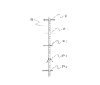
しかしながら、これらの従来技術では、全体の8〜9割のピンしか除去することができず、必ず残ピンが発生するという問題があった。特に、図2に示されるように、貝吊り用ピンが、ホタテ貝を外す際に強力な力で引きちぎられたことによって先端が延びて細くなったり(図2のP1)、切れて短くなったりしている(図2のP2)場合や、ホタテ貝の重さによって養殖ロープの近くで折れ曲がっている(図2のP3)場合、本来の取り付け状態からずれている(図2のP4)場合などには、貝吊り用ピンが引抜部に触れずに通過したり、引抜部において挟持されてもその力が不足したりすることによって、養殖ロープから除去されないことが多い。 However, these conventional techniques have a problem that only 80 to 90% of the pins can be removed, and the remaining pins are always generated. In particular, as shown in FIG. 2, when the shell suspending pin is torn off with a strong force when removing the scallop shell, the tip extends and narrows (P1 in FIG. 2), or it is cut and shortened. If it is bent (P2 in FIG. 2), or is bent near the culture rope due to the weight of the scallop (P3 in FIG. 2), it is not in the original attached state (P4 in FIG. 2), etc. In many cases, the pin for shell suspension passes without touching the pull-out portion, or is not removed from the aquaculture rope due to insufficient force even when pinned in the pull-out portion.
大口の漁家であれば年間で500万本もの貝吊り用ピンが使用される場合があり、中堅の漁家でも200万本もの貝吊り用ピンが使用されることがある。仮に、従来技術によって貝吊り用ピンを除去したときに養殖ロープに残るピンが1割であったとしても、その数は20万本〜50万本もの数になる。残った貝吊り用ピンは、ペンチなどを用いて手作業で除去せざるを得ず、その処理は漁家にとって大変な負担となっている。 A large fisherman may use 5 million shell hanging pins annually, and a mid-sized fisherman may also use 2 million shell hanging pins. Even if only 10% of the pins remain on the culture rope when the shell-suspending pins are removed by the conventional technique, the number is 200,000 to 500,000. The remaining shell suspending pins must be removed manually using pliers or the like, and the processing is a heavy burden on the fishermen.
また、養殖ロープが濡れている場合や汚れている場合、複数の養殖ロープが繋がれている場合などに、従来技術では、こうした養殖ロープをそのまま使用することが難しい。従来技術では、汚れたロープは事前の洗浄処理が必要であり、濡れたロープはある程度の乾燥処理が必要である。さらに、従来技術では、装置に養殖ロープをセットする工程が必要であり、その工程の存在も貝吊り用ピン除去の作業性を低下させる一因である。 In addition, when a culture rope is wet or dirty, or when a plurality of culture ropes are connected, it is difficult to use such a culture rope as it is in the conventional technology. In the prior art, dirty ropes require prior cleaning treatment and wet ropes require some degree of drying treatment. Furthermore, in the prior art, a process of setting a culture rope in the apparatus is necessary, and the presence of the process is one factor that reduces the workability of removing the pin for hanging the shell.
本発明は、簡単かつ確実にすべての貝吊り用ピンを養殖ロープから除去することが可能な除去装置を提供することを課題とする。 This invention makes it a subject to provide the removal apparatus which can remove all the pin for shellfishes easily and reliably from a culture rope.
上記の課題は、貝吊り用ピンに食い込むように形成され、回転軸方向に非直線的に並んだ突起を有する2つの回転体をできるだけ近接させて配置するとともに、貝吊り用ピンが差し込まれた養殖ロープをこれらの2つの回転体に近接させて走行させることにより、解決することができる。 The above-mentioned problem is formed so as to bite into the shell hanging pin, and the two rotating bodies having protrusions arranged in a non-linear manner in the rotation axis direction are arranged as close as possible, and the shell hanging pin is inserted This can be solved by running the culture rope close to these two rotating bodies.
本発明は、ロープに差し込まれている貝吊り用ピンをロープから除去するための貝吊り用ピン除去装置を提供する。この装置は、第1の回転体と、第1の回転体に近接して配置された第2の回転体とを有する。第1の回転体は、貝吊り用ピンに食い込む形状の複数の第1の突起を外表面に有し、中心軸の周りに回転する。第2の回転体は、貝吊り用ピンに食い込む形状の複数の第2の突起を外表面に有し、第1の回転体とは逆方向に中心軸の周りに回転するとともに、中心軸が第1の回転体の中心軸と概ね平行となるように配置される。複数の第1の突起及び複数の第2の突起のいずれか一方又は両方は、第1及び第2の回転体の中心軸の長さ方向に対して非直線的に並ぶように配置されている。貝吊り用ピンが差し込まれたロープが、第1及び第2の回転体に近接して第1及び第2の回転体の中心軸と概ね平行に走行するように構成されており、したがって、養殖ロープに挿入されている貝吊り用ピンは、第1の突起と第2の突起との間に挿入され、2つの回転体の回転に伴って養殖ロープから引き抜かれる。 The present invention provides a shell suspending pin removing device for removing a shell suspending pin inserted into a rope from the rope. This device has a first rotating body and a second rotating body arranged in proximity to the first rotating body. The first rotating body has a plurality of first protrusions shaped to bite into the shell hanging pins on the outer surface, and rotates around the central axis. The second rotating body has a plurality of second protrusions shaped to bite into the shell hanging pins on the outer surface, rotates around the central axis in a direction opposite to the first rotating body, and the central axis is It arrange | positions so that it may become substantially parallel with the central axis of a 1st rotary body. Either one or both of the plurality of first protrusions and the plurality of second protrusions are arranged so as to be aligned non-linearly with respect to the length direction of the central axis of the first and second rotating bodies. . The rope into which the pin for suspending the shell is inserted is configured to run close to the first and second rotating bodies and substantially parallel to the central axes of the first and second rotating bodies. The shell suspension pin inserted in the rope is inserted between the first protrusion and the second protrusion, and is pulled out from the culture rope as the two rotating bodies rotate.
一実施形態においては、複数の第1の突起は、第1の回転体の中心軸方向に対して不規則に配置されていることが好ましく、複数の第2の突起は、第2の回転体の中心軸方向に対して不規則に配置されていることが好ましい。第1の回転体と第2の回転体とは、第1の突起と前記第2の突起とが最も近づいたときの間隔が貝吊り用ピンの最も細い部分の太さより狭くなるように近接して配置されていることが好ましい。複数の第1及び第2の突起の各々には、貝吊りピンに食い込むように鋭角に形成された先端部が回転方向の前方部分に配されていることが好ましい。 In one embodiment, the plurality of first protrusions are preferably arranged irregularly with respect to the central axis direction of the first rotating body, and the plurality of second protrusions are the second rotating body. It is preferable to arrange irregularly with respect to the central axis direction. The first rotating body and the second rotating body are close to each other so that the distance when the first protrusion and the second protrusion are closest to each other is narrower than the thickness of the thinnest portion of the shell hanging pin. Are preferably arranged. Each of the plurality of first and second protrusions is preferably provided with a tip portion formed at an acute angle so as to bite into the shell suspension pin at a front portion in the rotational direction.
一実施形態においては、第1の回転体は、第1の円盤本体と該第1の円盤本体の外周面において円周方向に間隔を持って配置された複数の第1の突起とを各々が有する複数の第1の円盤が、回転軸の長さ方向に積層されて構成された、第1の円盤積層体とすることができる。同様に、第2の回転体は、第2の円盤本体と該第2の円盤本体の外周面において円周方向に間隔を持って配置された複数の第2の突起とを各々が有する複数の第2の円盤が、回転軸の長さ方向に積層されて構成された、第2の円盤積層体とすることができる。 In one embodiment, each of the first rotating bodies includes a first disk main body and a plurality of first protrusions arranged at intervals in the circumferential direction on the outer peripheral surface of the first disk main body. It can be set as the 1st disk laminated body comprised by laminating | stacking the several 1st disk to have in the length direction of the rotating shaft. Similarly, the second rotating body includes a plurality of second protrusions each having a second disk main body and a plurality of second protrusions arranged on the outer peripheral surface of the second disk main body at intervals in the circumferential direction. It can be set as the 2nd disk laminated body comprised by the 2nd disk being laminated | stacked on the length direction of the rotating shaft.
一実施形態においては、この装置は、第1及び第2の回転体に近接して走行するロープが第1及び第2の回転体に接触しないように保護するための保護部をさらに備えることがこのましい。保護部は、第1及び第2の回転体の中心軸と概ね平行に延びるように形成された隙間を有しており、該隙間は、第1の回転体と第2の回転体との間に対応する位置に配置されていることが好ましい。 In one embodiment, the apparatus further includes a protection unit for protecting a rope traveling in the vicinity of the first and second rotating bodies from coming into contact with the first and second rotating bodies. This is true. The protection part has a gap formed so as to extend substantially parallel to the central axes of the first and second rotating bodies, and the gap is between the first rotating body and the second rotating body. It is preferable to arrange | position in the position corresponding to.
保護部は、第1及び第2の回転体の中心軸と平行に延びる縁部を各々が有する2つの板状体を有することが好ましい。2つの板状体の縁部は、隙間を介して隣接するとともに第1及び第2の回転体に近接して配置されており、板状体の各々は、縁部を横切る方向の断面形状が略ヘの字形状を有することが好ましい。 It is preferable that the protection part has two plate-like bodies each having an edge extending in parallel with the central axis of the first and second rotating bodies. The edge portions of the two plate-like bodies are arranged adjacent to each other via a gap and close to the first and second rotating bodies, and each of the plate-like bodies has a cross-sectional shape in a direction crossing the edge portion. It preferably has a generally square shape.
一実施形態においては、この装置は、ロープを保護部の隙間に押し当てるための押さえ部材をさらに備えることが好ましい。押さえ部材は、保護部の隙間を横切る方向に延び、隙間から離れる方向に移動可能な棒状部材であることが好ましい。 In one embodiment, it is preferable that the device further includes a pressing member for pressing the rope against the gap of the protection unit. The pressing member is preferably a rod-shaped member that extends in a direction crossing the gap of the protective portion and is movable in a direction away from the gap.
本発明に係る装置によれば、従来技術では除去できずに養殖ロープに残っていたような貝吊り用ピンでも確実に養殖ロープから除去することができるため、残ったピンを事後的に手作業で除去する工程が不要であり、作業負担の低減、除去作業時間の短縮化を実現することができる。また、この装置は構造が簡単であるため、従来の複雑な構造の装置では必要であった事前の洗浄処理が不要であり、濡れた状態の養殖ロープや異物が付着した養殖ロープであっても、用いることができる。 According to the apparatus according to the present invention, even a pin for suspending a shell that cannot be removed by the prior art and remains on the culture rope can be surely removed from the culture rope. Thus, the process of removing by the step is unnecessary, and the work load can be reduced and the removal work time can be shortened. In addition, since this device has a simple structure, it does not require a pre-cleaning process that was necessary with a device having a complicated structure in the past, and even a wet culture rope or a culture rope with foreign matter attached thereto can be used. Can be used.
以下において、図面を参照しながら、本発明の実施形態を詳細に説明する。 Hereinafter, embodiments of the present invention will be described in detail with reference to the drawings.
[装置の構成]
図3及び図4は、一実施形態による貝吊り用ピン除去装置1の概略的な模式図であり、図3(a)は正面図、図3(b)は平面図、図4(a)は左側面図、図4(b)は右側面図である。貝吊り用ピン除去装置1は、図1及び図2に示されるようにホタテ貝Sの養殖に用いられる養殖ロープRに差し込まれている貝吊り用ピンPを、養殖ロープRから除去するための装置である。貝吊り用ピンPは、ホタテ貝Sが貝吊り用ピンPから外された時の力や、ホタテ貝Sの重さによって、図2のP1〜P4に示されるような状態になることが多く、このような状態の貝吊り用ピンPは、従来の装置では全てを養殖ロープRから除去することは難しかった。本発明による貝吊り用ピン除去装置1は、このような状態の貝吊り用ピンP1〜P4であっても、養殖ロープPから確実に除去することができる。
[Device configuration]
FIGS. 3 and 4 are schematic views of a shell suspending
貝吊り用ピン除去装置1は、図3及び図4に示されるように、筐体2の内部に、モータ3と、モータ3の回転力によって動作するピン除去ユニット4とを有する。筐体2は、全体を覆う上部筐体21(点線で示されている)と、モータ3及びピン除去ユニット4を支持する下部筐体22とを有する。筐体2の下方の一部には、ピン除去ユニット4によって養殖ロープRから除去された貝吊り用ピンPを排出するピン排出口23が設けられている。
As shown in FIG. 3 and FIG. 4, the shell suspending
モータ3の回転軸31には、大径の歯車32が取り付けられており、歯車32が、ピン除去ユニット4に設けられた歯車48と噛み合うことによって、ピン除去ユニット4を回転させることができる。モータ3の回転軸31及びピン除去ユニット4は、支持部24によって支持されている。
A large-
図5を用いて、貝吊り用ピン除去装置1に用いられるピン除去ユニット4を説明する。図5(a)は、ピン除去ユニット4の正面図、図5(b)は左側面図、図5(c)は右側面図である。また、図5(d)は、ピン除去ユニット4の円盤積層体44を構成する円盤を示す。
The
ピン除去ユニット4は、2つのサブユニット41a及び41bから構成される。サブユニット41aは、回転軸42aの一方の端部側(図5(a)では回転軸42aの中央より左側)に円盤積層体(第1の回転体)44aが取り付けられ、回転軸42aの他端部(図5(a)では回転軸42aの右端部)に歯車48aが取り付けられている。同様に、サブユニット41bは、回転軸42bの一方の端部側に円盤積層体(第2の回転体)44bが取り付けられ、回転軸42bの他端部に歯車48bが取り付けられている。回転軸42aと回転軸42bとは、概ね平行に配置される。
The
ピン除去ユニット4は、モータ3の回転軸31に取り付けられた歯車32が、歯車48a又は48bと噛み合うことによって、回転する。この実施形態においては、歯車32は、図4(b)に示されるようにピン除去ユニット4の歯車48bと噛み合っており、歯車48aと48bとは、図4(b)及び図5(b)に示されるように互いに噛み合っているため、モータ3の動力は、回転軸31、歯車32、歯車48b、歯車48aと伝達されて、ピン除去ユニット4の回転軸42a、42bを回転させる。回転軸42aと回転軸42bとは、図5に示されるように、互いに逆方向に回転する。一実施形態においては、例えば回転軸42a、42bの回転数は、毎分100〜200回転程度とすることができる。
The
円盤積層体44aは、複数の円盤(第1の円盤)44a1が回転軸42aの長さ方向に重ねられることによって構成される。複数の円盤44a1の各々は、図5(d)に示されるように、円盤本体(第1の円盤本体)442aと、円盤本体442aの外周面443aにおいて間隔を持って周方向に配置された複数の突起(第1の突起)444aとを有する。複数の突起444aの各々は、通常の歯車の歯のような単なる山形ではなく、鋸刃状に形成されており、回転方向Aの前方部分に鋭角の先端部448aを有する。突起444aは、図5(d)に示される形状に限定されるものではなく、樹脂製の貝吊り用ピンPに食い込みやすい形状に形成されていればよい。 The disk stack 44a is configured by stacking a plurality of disks (first disks) 44a1 in the length direction of the rotation shaft 42a. As shown in FIG. 5 (d), each of the plurality of disks 44a1 includes a plurality of disk bodies (first disk body) 442a and a plurality of disks 44a1 arranged in the circumferential direction at intervals on the outer peripheral surface 443a of the disk body 442a. Projections (first projections) 444a. Each of the plurality of protrusions 444a is not a simple chevron like a normal gear tooth, but is formed in a saw blade shape, and has a sharp tip 448a at the front portion in the rotation direction A. The protrusion 444a is not limited to the shape shown in FIG. 5D, and may be formed in a shape that can easily bite into the resin-made shell-hanging pin P.
円盤積層体44bも、円盤積層体44a同様に構成されている。すなわち、円盤積層体44bは、複数の円盤(第2の円盤)44b1が回転軸42bの長さ方向に重ねられることによって構成される。複数の円盤44b1の各々は、円盤本体(第2の円盤本体)442bと、円盤本体442bの外周面443bにおいて間隔を持って周方向に配置された複数の突起(第2の突起)444bとを有する。複数の突起444bの各々は、回転方向Aの前方部分に鋭角の先端部448bを有する。突起444bは、樹脂製の貝吊り用ピンPに食い込みやすい形状に形成されていればよい。 The disk stack 44b is configured in the same manner as the disk stack 44a. That is, the disk stack 44b is configured by stacking a plurality of disks (second disks) 44b1 in the length direction of the rotation shaft 42b. Each of the plurality of disks 44b1 includes a disk main body (second disk main body) 442b and a plurality of protrusions (second protrusions) 444b arranged in the circumferential direction at intervals on the outer peripheral surface 443b of the disk main body 442b. Have. Each of the plurality of protrusions 444b has an acute end portion 448b at the front portion in the rotation direction A. The protrusion 444b only needs to be formed in a shape that easily bites into the resin shell-hanging pin P.
円盤積層体44aと円盤積層体44bとは、できるだけ近接して配置されることが好ましい。すなわち、円盤積層体44aと円盤積層体44bとは、各々の突起444aと444b(より具体的には、それぞれの先端部448aと448b)が最も近づいたときの両者の間隔が養殖用ロープRから除去しようとする貝吊り用ピンPの最も細い部分の太さより狭くなるように調整されることが好ましく、各々の突起444aと444bが互いに接触しない限界の間隔で対向するように配置されることが好ましい。 The disk stack 44a and the disk stack 44b are preferably arranged as close as possible. That is, the disc laminate 44a and the disc laminate 44b are separated from the culture rope R when the protrusions 444a and 444b (more specifically, the respective tip portions 448a and 448b) are closest to each other. It is preferable that the thickness is adjusted so as to be narrower than the thinnest part of the shell-pushing pin P to be removed, and the protrusions 444a and 444b are arranged so as to face each other at a limit interval where they do not contact each other. preferable.
円盤積層体44aにおいては、各々の円盤44a1の突起444aが、円盤積層体44aの積層方向(すなわち、回転軸42aの長さ方向)に対して非直線的に並ぶように配置されている。ここで、突起444aが非直線的に並ぶように配置とは、複数の円盤44a1間で、隣接する突起444aが円盤44a1の円周方向に一定の角度ずつずれるように配置される場合(すなわち、直線的ではないが規則的に並ぶ場合)や、突起444aが不規則に配置される場合(すなわち、直線的でも規則的でもない場合)も含む。円盤積層体44bにおいても、円盤積層体44aと同様に、各々の円盤44b1の突起444bが、円盤積層体44bの積層方向(すなわち、回転軸42bの長さ方向)に対して非直線的に並ぶように配置されている。 In the disk stack 44a, the protrusions 444a of the respective disks 44a1 are arranged so as to be arranged non-linearly with respect to the stacking direction of the disk stack 44a (that is, the length direction of the rotating shaft 42a). Here, the arrangement in which the protrusions 444a are arranged non-linearly means that the adjacent protrusions 444a are arranged so as to be shifted by a certain angle in the circumferential direction of the disks 44a1 between the plurality of disks 44a1 (that is, This includes the case where the protrusions 444a are irregularly arranged (that is, neither linear nor regular). Also in the disk stack 44b, similar to the disk stack 44a, the protrusions 444b of the respective disks 44b1 are arranged non-linearly with respect to the stacking direction of the disk stack 44b (that is, the length direction of the rotating shaft 42b). Are arranged as follows.
この実施形態においては、円盤積層体44a及び44bのいずれも、突起444aが非直線的に並ぶように配置されているが、これに限定されるものではなく、別の実施形態においては、円盤積層体44a及び44bのいずれか一方の突起が非直線的に並ぶように配置し、他方の突起が直線的に並ぶように配置してもよい。このようにして、貝吊り用ピンに食い込む突起が形成された複雑な表面形状の円盤積層体を得ることができる。 In this embodiment, both of the disk stacks 44a and 44b are arranged so that the protrusions 444a are arranged in a non-linear manner, but the present invention is not limited to this, and in another embodiment, It may be arranged such that one of the protrusions of the bodies 44a and 44b is arranged in a non-linear manner and the other protrusion is arranged in a straight line. In this way, it is possible to obtain a disk stack having a complicated surface shape in which protrusions that bite into the shell-suspending pins are formed.
好ましくは、回転軸42a及び42bは、円盤積層体44a及び44bが配置される部分が他の部分より細く形成されることが好ましい。このように形成することにより、複数の円盤44a1及び44b1が積層された円盤積層体44a及び44bを、回転軸42a及び42bの太くなった部分の端面と円盤積層体止め46a及び46bとの間に挟んで、確実に固定することができる。 Preferably, the rotation shafts 42a and 42b are formed so that the portions where the disk stacks 44a and 44b are disposed are thinner than the other portions. By forming in this way, the disk stacks 44a and 44b in which a plurality of disks 44a1 and 44b1 are stacked are placed between the end surfaces of the thickened portions of the rotating shafts 42a and 42b and the disk stack stops 46a and 46b. It can be pinched and fixed securely.
本実施形態においては、円盤積層体44a、44bは、複数の円盤44a1、44b1が互いに接するように配置されているが、これに限定されるものではなく、隣接する円盤44a1、44b1の間にスペーサを設けて複数の円盤44a1、44b1を積層してもよい。 In the present embodiment, the disk stacks 44a and 44b are arranged so that the plurality of disks 44a1 and 44b1 are in contact with each other. However, the present invention is not limited to this, and a spacer is provided between the adjacent disks 44a1 and 44b1. A plurality of disks 44a1 and 44b1 may be stacked.
一実施形態においては、円盤積層体44a、44bの円盤44a1、44b1の各々は、例えばレーザ切断機を用いて図5(d)の形状に切り出すことによって形成することができる。円盤44a1、44b1の各々の厚さは、貝吊り用ピンPへの食い込みの良さと強度とを考慮すると、厚さ2mm〜3mm程度であることが好ましいが、これに限定されるものではなく、より厚い円盤や薄い円盤を用いることもでき、厚さの異なる複数の円盤を用いることもできる。一実施形態においては、円盤44a1、44b1の外径Dは、例えば20mm程度とすることができるが、製作可能な範囲でできるだけ小さくすることが好ましい。突起444a、444bの外端部分の円周方向長さlは、例えば2mm〜3mm程度とすることができるが、これに限定されるものではない。一実施形態においては、限定されるものではないが、円盤積層体44a、44bは、例えば円盤44a1、44b1を20枚〜30枚程度重ねることによって形成することが好ましい。 In one embodiment, each of the disks 44a1 and 44b1 of the disk stacks 44a and 44b can be formed by cutting into the shape of FIG. 5D using a laser cutting machine, for example. The thickness of each of the disks 44a1 and 44b1 is preferably about 2 mm to 3 mm in thickness considering the goodness and strength of biting into the shell hanging pin P, but is not limited thereto. A thicker disk or a thinner disk can be used, and a plurality of disks having different thicknesses can also be used. In one embodiment, the outer diameter D of the disks 44a1 and 44b1 can be, for example, about 20 mm, but it is preferable to make it as small as possible within a manufacturable range. The circumferential length l of the outer end portions of the protrusions 444a and 444b can be, for example, about 2 mm to 3 mm, but is not limited thereto. In one embodiment, although not limited, the disk stacks 44a and 44b are preferably formed by stacking, for example, about 20 to 30 disks 44a1 and 44b1.
本実施形態の貝吊り用ピン除去装置1においては、ピン除去ユニット4は、回転軸42a及び42bに円盤積層体44a及び44bが取り付けられた構成であるが、これに限定されるものではない。別の実施形態においては、ピン除去ユニット4は、回転軸42a、42bに、各々が外表面を有する回転体44a’、44b’が取り付けられ、その外表面に、貝吊り用ピンPに食い込む形状の複数の突起を有する構成のものとすることもできる。
In the
この実施形態においては、回転体(第1の回転体)44a’は、回転体本体442a’(円盤積層体44aの複数の円盤本体442aに相当する)の外表面443a’(複数の円盤442aの外表面443aに相当する)に、複数の突起(第1の突起)444a’(複数の突起444aに相当する)が設けられたものとすることができる。複数の突起444a’は、回転軸42aの長さ方向に対して非直線的に並ぶように、外表面443a’に配置される。回転体本体442a’の形状は、円筒状の外形であることが好ましいが、これに限定されるものではなく、例えば多角形の外形を有するものとすることもできる。この場合には、複数の突起444a’によって形成される外形が略円筒形状となるように、高さの異なる複数の突起444a’が外表面443a’に配置されることが好ましい。 In this embodiment, the rotating body (first rotating body) 44a ′ is an outer surface 443a ′ (corresponding to the plurality of disk bodies 442a of the disk stack 44a) of the rotating body main body 442a ′ (the plurality of disks 442a). A plurality of protrusions (first protrusions) 444a ′ (corresponding to the plurality of protrusions 444a) may be provided on the outer surface 443a. The plurality of protrusions 444a 'are arranged on the outer surface 443a' so as to be aligned non-linearly with respect to the length direction of the rotation shaft 42a. The shape of the rotator main body 442a 'is preferably a cylindrical outer shape, but is not limited thereto, and may have, for example, a polygonal outer shape. In this case, it is preferable that the plurality of protrusions 444a 'having different heights are arranged on the outer surface 443a' so that the outer shape formed by the plurality of protrusions 444a 'is substantially cylindrical.
回転体(第2の回転体)44b’についても、回転体44a’と同様に、回転体本体442b’の外表面443b’に、複数の突起(第2の突起)444b’が設けられたものとすることができる。複数の突起444b’は、回転軸42bの長さ方向に対して非直線的に並ぶように、外表面443b’に配置される。回転体本体442b’の形状は、円筒状の外形であることが好ましいが、これに限定されるものではなく、例えば多角形の外形を有するものとすることもできる。 The rotating body (second rotating body) 44b ′ is also provided with a plurality of protrusions (second protrusions) 444b ′ on the outer surface 443b ′ of the rotating body main body 442b ′ in the same manner as the rotating body 44a ′. It can be. The plurality of protrusions 444b 'are arranged on the outer surface 443b' so as to be aligned non-linearly with respect to the length direction of the rotation shaft 42b. The shape of the rotator main body 442b 'is preferably a cylindrical outer shape, but is not limited thereto, and may have, for example, a polygonal outer shape.
貝吊り用ピン除去装置1は、図3及び図4に示されるように、ピン除去ユニット4の円盤積層体44a及び44bの上部に、保護部5を備えることが好ましい。保護部5は、養殖ロープRと円盤積層体44a、44bとができるだけ近接するようにしながら、養殖ロープRから貝吊り用ピンPが除去される際に養殖ロープRが円盤積層体44a及び44bに接触しないように保護する機能を有する。図6(a)は、保護部5を示し、図6(b)は、保護部5と養殖ロープR及び貝吊り用ピンPとの間の位置関係を示す。
As shown in FIGS. 3 and 4, the shell suspending
本実施形態においては、保護部5は、2枚の板状体51a及び51bを有する。板状体51aは、水平部材511aと傾斜部材512aとを有し、板状体51bは、水平部材511bと傾斜部材512bとを有する。筐体2の上面には、円盤積層体44aと円盤積層体44bの間に対応する位置に開口25(図6(b))が設けられており、板状体51a、51bは、傾斜部材512a、512bが筐体2の開口25内に入り込むように、水平部材511a、511bが筐体2の上面に、例えば溶接又はねじ止めなどによって取り付けられる。
In the present embodiment, the
板状体51aの縁部513aと板状体51bの縁部513bとの間には、隙間52が設けられている。縁部513a及び513bは、円盤積層体44a、44bの中心軸と概ね平行に延びるように形成されており、隙間52は、円盤積層体44a、44bの中心軸と概ね平行に延びるとともに、円盤積層体44aと円盤積層対44bとの間に対応する位置に配置されるように、保護部5に形成されている。貝吊り用ピンPが差し込まれた状態の養殖ロープRは、その長さ方向が隙間52の長さ方向と平行になるように、隙間52の間を走行する。
A gap 52 is provided between the edge 513a of the plate-like body 51a and the edge 513b of the plate-like body 51b. The edges 513a and 513b are formed to extend substantially parallel to the central axis of the disk stacks 44a and 44b, and the gap 52 extends substantially parallel to the central axis of the disk stacks 44a and 44b. The
保護部5の板状体51aは、円盤積層体44aにできるだけ近接するように配置され、板状体51bは、円盤積層体44bにできるだけ近接するように配置される。また、板状体51a及び51bは、図6に示されるように、傾斜部材512a、512bと水平部材511a、511bとによって、縁部513a、513bを横切る方向の断面形状が略ヘの字形状を有するように形成されている。断面形状が略への字形状に形成されることによって、図6(b)に示されるように、対向する縁部513a及び513bを、円盤積層体44aと44bとの間において円盤積層体44a及び44bに極めて近接させることができる。
The plate-like body 51a of the
保護部5の隙間52は、養殖ロープRの径より狭く、貝吊り用ピンPの最も太い部分の径より広いことが好ましいが、これに限定されるものではなく、養殖ロープRの径より広くすることもできる。隙間52が養殖ロープRの径より広くても、保護部5によって養殖ロープRが円盤積層体44a、44bに接触しないように構成されていればよい。
The gap 52 of the
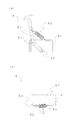
貝吊り用ピン除去装置1は、図3及び図4に示されるように、保護部5の上にロープ押さえ部6を備えることが好ましい。ロープ押さえ部6は、養殖ロープRを上から押さえて隙間52に当てるように機能する。図7は、ロープ押さえ部6を示し、図7(a)は正面図、図7(b)は平面図を示す。
As shown in FIGS. 3 and 4, the shell suspending
ロープ押さえ部6は、筐体2の上面に立設された支持部材61と、バネ62を介して支持部材61と連結され、支点64の周りに回転可能なレバー63と、押さえ部材65とを有する。支持部材61は、例えば溶接又はねじ止めなどにより筐体2に直接取り付けることができるが、図7(b)に示されるように、支持部材61との間でL字形状をなすように形成されたベース部材67を筐体2の上面に取り付けてもよいし、支持部材61を保護部5に取り付けてもよい。
The
押さえ部材65は、レバー63の下端において、レバー63の長さ方向と直交する方向にレバー3から突出するように設けられている。したがって、後に説明する図8に示されるように、押さえ部材65は、保護部5の隙間52に配置されて移動する養殖ロープRを、バネ62の力で上から隙間52に押し当てることができる。支点64を中心としてレバー63を矢印の方向にはね上げることにより、押さえ部材65を養殖ロープRから離れる方向に移動させることができる。
The pressing
[装置の使用方法]
以下に、本発明による貝吊り用ピン除去装置1の使用方法を説明する。
図8は、貝吊り用ピン除去装置1の使用状態を示す。まず、貝吊り用ピン除去装置1のモータ3を作動させ、ピン除去ユニット4の円盤積層体44a及び44bを、互いに逆方向に回転させる。回転方向は、例えば図6及び図8に示される矢印の方向である。
[How to use the device]
Below, the usage method of the
FIG. 8 shows the usage state of the
ロープ押さえ部6のレバー63を、図7に示される矢印の方向に倒すことにより、押さえ部材65を上方に移動させる。押さえ部材65を上方に移動させた後、貝吊り用ピンPが差し込まれた状態の養殖ロープRを、保護部5の板状体51a及び51bの間の隙間52に沿って配置する。次いで、押さえ部6のレバー63を戻すことにより、押さえ部材65を養殖ロープRを横切る向きで配置させる。養殖ロープRは、押さえ部6のバネ62の力によって、隙間52に押し付けられる。
The pressing
次に、養殖ロープRを、図8の白抜き矢印で示される方向に移動させる。養殖ロープRは、この実施形態においては作業者が移動させることが想定されている。しかしながら、例えば、養殖ロープRの移動方向下流側に養殖ロープRを巻き取る装置を配置するとともに、養殖ロープRの移動方向上流側において養殖ロープRを保護部5の隙間52に導くガイド装置を配置することによって、自動で養殖ロープRを移動させながら貝吊り用ピンPを除去することもできる。
Next, the culture rope R is moved in the direction indicated by the white arrow in FIG. The culture rope R is assumed to be moved by an operator in this embodiment. However, for example, a device for winding the culture rope R is arranged on the downstream side in the movement direction of the culture rope R, and a guide device for guiding the culture rope R to the gap 52 of the
養殖ロープRに差し込まれている貝吊り用ピンPは、養殖ロープRが隙間52に沿って移動すると、図6(b)に示されるように隙間52に入り、ピン抜きユニット4の2つの円盤積層体44aと44bとの間に送り込まれる。円盤積層体44aと44bとの間に送り込まれた貝吊り用ピンPは、円盤積層体44a、44bの非直線的に並んだ突起444a、444bによって、確実に養殖ロープRから引き抜かれる。 When the culture rope R moves along the gap 52, the shell hanging pin P inserted into the culture rope R enters the gap 52 as shown in FIG. It is fed between the laminates 44a and 44b. The shell suspension pin P fed between the disk stacks 44a and 44b is reliably pulled out from the culture rope R by the non-linearly arranged protrusions 444a and 444b of the disk stacks 44a and 44b.
すなわち、各々の突起444a、444bが、非直線的に並ぶように且つ両者の間隔が近接するように配置されていることによって、例えば先端部448aと448bとが対向する位置関係にある箇所では、両方の先端部448aと448bとが貝吊り用ピンPの両側から食い込んでピンPを下方に引くとともに、ピンPが引かれることによって下向きに力がかかった養殖ロープRを保護部5が制止することにより、貝吊り用ピンPを養殖ロープRから確実に引き抜くことができる。別の場所において、例えば円盤積層体44aの先端部448aと円盤積層体44bの谷446bとが対向する位置関係にある箇所では、先端部448aが貝吊り用ピンPに食い込んでピンPを谷448bに送り込みながら下方に引くとともに、ピンPが引かれることによって下向きに力がかかった養殖ロープRを保護部5が制止することにより、貝吊り用ピンPを養殖ロープRから確実に引き抜くことができる。このように、貝吊り用ピンPが円盤積層体44a、44bの回転によって下方に引かれるときの仕組みが、円盤積層体44a、44bの長さ方向及び円周方向において様々であるため、養殖ロープRが移動して貝吊り用ピンPが円盤積層体44a、44bの前端から後端まで進行する間のいずれかの位置で、貝吊り用ピンPは養殖ロープRから確実に除去されることになる。
That is, by arranging the protrusions 444a and 444b so as to be arranged in a non-linear manner and so that the distance between them is close, for example, at a position where the tip portions 448a and 448b are opposed to each other, Both tip portions 448a and 448b bite in from both sides of the shell suspension pin P and pull the pin P downward, and the
養殖ロープRから除去された貝吊り用ピンPは、円盤積層体44aと44bとの間から下方に落下し、円盤積層体44a、44bの下方において筐体2に設けられたピン排出口23から、装置1の外に排出される。
The shell suspension pin P removed from the culture rope R falls downward from between the disk stacks 44a and 44b, and from the
1 貝吊り用ピン除去装置
2 筐体
21 上部筐体
22 下部筐体,
23 ピン排出口
24 支持部
25 開口
3 モータ
31 回転軸
32 歯車
4 ピン除去ユニット
41a サブユニット
42a 中心軸
44a 円盤積層体(第1の回転体)
44a1 (第1の)円盤
442a (第1の)円盤本体
443a 外表面
444a (第1の)突起
446a 谷
448a 先端部
46a 円盤積層体止め
48a 歯車
41b サブユニット
42a 中心軸
44b 円盤積層体(第2の回転体)
44b1 (第2の)円盤
442b (第2の)円盤本体
443b 外表面
444b (第2の)突起
446b 谷
448b 先端部
46b 円盤積層体止め
48b 歯車
5 保護部
51a、51b 板状体
511a、511b 水平部材
512a、512b 傾斜部材
513a、513b 縁部
52 隙間
6 ロープ押さえ部
61 支持部材
62 バネ
63 レバー
64 支点
65 押さえ部材
67 ベース部材
P 貝吊り用ピン
R 養殖ロープ
S ホタテ貝
DESCRIPTION OF
23
44a1 (first) disk 442a (first) disk body 443a outer surface 444a (first) protrusion 446a valley 448a tip 46a disk stack stop 48a gear 41b subunit 42a central shaft 44b disk stack (second) Rotating body)
44b1 (second) disk 442b (second) disk body 443b outer surface 444b (second) protrusion 446b valley 448b tip 46b disk stack
Claims (11)
貝吊り用ピンに食い込む形状の複数の第1の突起を外表面に有し、中心軸の周りに回転する、第1の回転体と、
貝吊り用ピンに食い込む形状の複数の第2の突起を外表面に有し、前記第1の回転体とは逆方向に中心軸の周りに回転するとともに、中心軸が前記第1の回転体の中心軸と概ね平行である、前記第1の回転体に近接して配置された第2の回転体と、
を備え、
前記複数の第1の突起及び前記複数の第2の突起のいずれか一方又は両方は、前記第1及び第2の回転体の中心軸の長さ方向に対して非直線的に並ぶように配置されており、
貝吊り用ピンが差し込まれたロープが、前記第1及び第2の回転体に近接して前記第1及び第2の回転体の中心軸と概ね平行に走行することにより、貝吊り用ピンが前記第1の突起と前記第2の突起との間に挿入されるように構成された、貝吊り用ピン除去装置。 A shell suspending pin removing device for removing a shell suspending pin inserted into a rope from the rope,
A first rotating body having a plurality of first protrusions shaped to bite into a shell hanging pin on the outer surface and rotating around a central axis;
A plurality of second protrusions shaped to bite into the shell-suspending pins are provided on the outer surface, rotate around the central axis in a direction opposite to the first rotary body, and the central axis is the first rotary body A second rotating body disposed in proximity to the first rotating body and being substantially parallel to the central axis of
With
One or both of the plurality of first protrusions and the plurality of second protrusions are arranged so as to be aligned non-linearly with respect to the length direction of the central axis of the first and second rotating bodies. Has been
The rope into which the shell hanging pin is inserted travels in parallel with the central axes of the first and second rotating bodies in the vicinity of the first and second rotating bodies, so that the shell hanging pins are A pin removal device for hanging shells configured to be inserted between the first protrusion and the second protrusion.
前記第2の回転体は、第2の円盤本体と該第2の円盤本体の外周面において円周方向に間隔を持って配置された前記複数の第2の突起とを各々が有する複数の第2の円盤が、回転軸の長さ方向に積層されて構成された、第2の円盤積層体である、
請求項1から請求項8までのいずれか1項に記載の貝吊り用ピン除去装置。 The first rotating body includes a plurality of first protrusions each having a first disk main body and the plurality of first protrusions arranged on the outer peripheral surface of the first disk main body at intervals in the circumferential direction. 1 disk is a first disk stack formed by stacking in the length direction of the rotating shaft,
The second rotating body includes a plurality of second protrusions each having a second disk main body and the plurality of second protrusions arranged at intervals in the circumferential direction on the outer peripheral surface of the second disk main body. The second disk stack is configured by stacking two disks in the length direction of the rotation axis.
The pin removal apparatus for shell suspensions of any one of Claim 1- Claim 8.
The pin removal device for shell suspension according to claim 9, wherein either one or both of the first disk stack and the second disk stack further includes a spacer disposed between the adjacent disks. .
Priority Applications (1)
| Application Number | Priority Date | Filing Date | Title |
|---|---|---|---|
| JP2016237945A JP6865953B2 (en) | 2016-12-07 | 2016-12-07 | Shell hanging pin removal device |
Applications Claiming Priority (1)
| Application Number | Priority Date | Filing Date | Title |
|---|---|---|---|
| JP2016237945A JP6865953B2 (en) | 2016-12-07 | 2016-12-07 | Shell hanging pin removal device |
Publications (2)
| Publication Number | Publication Date |
|---|---|
| JP2018093733A true JP2018093733A (en) | 2018-06-21 |
| JP6865953B2 JP6865953B2 (en) | 2021-04-28 |
Family
ID=62631175
Family Applications (1)
| Application Number | Title | Priority Date | Filing Date |
|---|---|---|---|
| JP2016237945A Active JP6865953B2 (en) | 2016-12-07 | 2016-12-07 | Shell hanging pin removal device |
Country Status (1)
| Country | Link |
|---|---|
| JP (1) | JP6865953B2 (en) |
Citations (16)
| Publication number | Priority date | Publication date | Assignee | Title |
|---|---|---|---|---|
| JPS5250896A (en) * | 1975-10-22 | 1977-04-23 | Chiyoukichi Watanabe | Process and apparatus for removing foreign substances from shell surfaces of cultured shellfishes |
| US4270488A (en) * | 1977-10-03 | 1981-06-02 | Kennedy George D | System and apparatus for cultivating and harvesting oysters |
| JPS587557U (en) * | 1981-07-10 | 1983-01-18 | 株式会社 青森養殖機器 | Automatic cleaner for deposits on drooping cultured shellfish |
| JPS58100083U (en) * | 1981-12-25 | 1983-07-07 | ト−ハタ株式会社 | washing device |
| JPS58111027U (en) * | 1982-01-25 | 1983-07-28 | 株式会社青森養殖機器 | Rotating brush for removing deposits from cultured shellfish |
| JPH0438258U (en) * | 1990-07-25 | 1992-03-31 | ||
| JPH0438259U (en) * | 1990-07-25 | 1992-03-31 | ||
| JPH0474953U (en) * | 1990-11-15 | 1992-06-30 | ||
| CN1114854A (en) * | 1994-07-15 | 1996-01-17 | 杉山弘昭 | Tools for hanging shell |
| JPH08275691A (en) * | 1995-04-07 | 1996-10-22 | Eagle Ind Co Ltd | Equipment for hanging cultivated shell at its ear edge |
| JP3114449U (en) * | 2005-07-06 | 2005-10-27 | 株式会社東北総合研究社 | Lock pin for cultured scallop |
| JP4005998B2 (en) * | 2004-10-19 | 2007-11-14 | 有限会社金平鉄工所 | Extraction device for suspension pin for cultured shellfish |
| JP2009159872A (en) * | 2007-12-29 | 2009-07-23 | Mutsu Kaden Tokki:Kk | Method for arranging shellfish fastener, method for pulling-out shellfish fastener, method for arranging and pulling-out shellfish fastener, tool for arranging shellfish fastener, tool for pulling-out shellfish fastener and apparatus for pulling-out shellfish fastener |
| JP2010099087A (en) * | 2010-01-20 | 2010-05-06 | Mutsu Kaden Tokki:Kk | Surface cleaner for shellfish |
| JP2012005373A (en) * | 2010-06-22 | 2012-01-12 | Mutsu Kaden Tokki:Kk | Method and device for removing shellfish fastening implement |
| JP2015198636A (en) * | 2014-04-01 | 2015-11-12 | 株式会社東北総合研究社 | Scallop cultivation fastening pin and scallop harvest method |
-
2016
- 2016-12-07 JP JP2016237945A patent/JP6865953B2/en active Active
Patent Citations (16)
| Publication number | Priority date | Publication date | Assignee | Title |
|---|---|---|---|---|
| JPS5250896A (en) * | 1975-10-22 | 1977-04-23 | Chiyoukichi Watanabe | Process and apparatus for removing foreign substances from shell surfaces of cultured shellfishes |
| US4270488A (en) * | 1977-10-03 | 1981-06-02 | Kennedy George D | System and apparatus for cultivating and harvesting oysters |
| JPS587557U (en) * | 1981-07-10 | 1983-01-18 | 株式会社 青森養殖機器 | Automatic cleaner for deposits on drooping cultured shellfish |
| JPS58100083U (en) * | 1981-12-25 | 1983-07-07 | ト−ハタ株式会社 | washing device |
| JPS58111027U (en) * | 1982-01-25 | 1983-07-28 | 株式会社青森養殖機器 | Rotating brush for removing deposits from cultured shellfish |
| JPH0438258U (en) * | 1990-07-25 | 1992-03-31 | ||
| JPH0438259U (en) * | 1990-07-25 | 1992-03-31 | ||
| JPH0474953U (en) * | 1990-11-15 | 1992-06-30 | ||
| CN1114854A (en) * | 1994-07-15 | 1996-01-17 | 杉山弘昭 | Tools for hanging shell |
| JPH08275691A (en) * | 1995-04-07 | 1996-10-22 | Eagle Ind Co Ltd | Equipment for hanging cultivated shell at its ear edge |
| JP4005998B2 (en) * | 2004-10-19 | 2007-11-14 | 有限会社金平鉄工所 | Extraction device for suspension pin for cultured shellfish |
| JP3114449U (en) * | 2005-07-06 | 2005-10-27 | 株式会社東北総合研究社 | Lock pin for cultured scallop |
| JP2009159872A (en) * | 2007-12-29 | 2009-07-23 | Mutsu Kaden Tokki:Kk | Method for arranging shellfish fastener, method for pulling-out shellfish fastener, method for arranging and pulling-out shellfish fastener, tool for arranging shellfish fastener, tool for pulling-out shellfish fastener and apparatus for pulling-out shellfish fastener |
| JP2010099087A (en) * | 2010-01-20 | 2010-05-06 | Mutsu Kaden Tokki:Kk | Surface cleaner for shellfish |
| JP2012005373A (en) * | 2010-06-22 | 2012-01-12 | Mutsu Kaden Tokki:Kk | Method and device for removing shellfish fastening implement |
| JP2015198636A (en) * | 2014-04-01 | 2015-11-12 | 株式会社東北総合研究社 | Scallop cultivation fastening pin and scallop harvest method |
Also Published As
| Publication number | Publication date |
|---|---|
| JP6865953B2 (en) | 2021-04-28 |
Similar Documents
| Publication | Publication Date | Title |
|---|---|---|
| US9610585B2 (en) | Shredder support frame | |
| JP2008253216A (en) | Rotary cutter for bush cutter | |
| US20070063086A1 (en) | Image forming apparatus | |
| JP5403758B2 (en) | Waste recovery equipment for optical fiber cutting equipment | |
| US7818886B1 (en) | Anti-pinch chainsaw bar assembly | |
| JP2018093733A (en) | Shellfish hanging pin removal apparatus | |
| US9409720B2 (en) | Medium carrying mechanism | |
| KR101483477B1 (en) | Drawing shaping device and drawing molding machine using the same | |
| KR20170069367A (en) | apparatus for pulling traps | |
| JP5852322B2 (en) | Recycled paper winding device and winding method thereof | |
| JP2004107020A (en) | Paper sheet conveyer, and conveyer belt for paper sheet | |
| US10737274B2 (en) | Apparatus for shredding value documents | |
| KR101746674B1 (en) | Rotary-type Holding Device for Floor Mat Rolls | |
| CN218277908U (en) | Feeding roller of hay cutter | |
| JP2006220696A (en) | Device for inserting optical fiber into protective tube | |
| JP6828321B2 (en) | Processing machine, settlement device, settlement machine and processing method for processing coin rolls | |
| JP2005081478A (en) | Trimming cutter for laminated sheet material | |
| JP6156292B2 (en) | Sheet post-processing apparatus and image forming apparatus | |
| KR20110092827A (en) | Reeling apparatus of fishing lone line | |
| JP6884384B2 (en) | Pin orientation correction unit for shell hanging | |
| JP5387449B2 (en) | Corrugated tube feeder | |
| JP6529162B2 (en) | Stacker and control method thereof | |
| JP2005161426A (en) | Cutter of drum vessel | |
| JP2006198814A (en) | Manufacturing method of cushioning material made of paper | |
| JP2009126687A5 (en) |
Legal Events
| Date | Code | Title | Description |
|---|---|---|---|
| A621 | Written request for application examination |
Free format text: JAPANESE INTERMEDIATE CODE: A621 Effective date: 20191029 |
|
| A977 | Report on retrieval |
Free format text: JAPANESE INTERMEDIATE CODE: A971007 Effective date: 20201116 |
|
| A131 | Notification of reasons for refusal |
Free format text: JAPANESE INTERMEDIATE CODE: A131 Effective date: 20201201 |
|
| A521 | Request for written amendment filed |
Free format text: JAPANESE INTERMEDIATE CODE: A523 Effective date: 20210113 |
|
| TRDD | Decision of grant or rejection written | ||
| A01 | Written decision to grant a patent or to grant a registration (utility model) |
Free format text: JAPANESE INTERMEDIATE CODE: A01 Effective date: 20210323 |
|
| A61 | First payment of annual fees (during grant procedure) |
Free format text: JAPANESE INTERMEDIATE CODE: A61 Effective date: 20210331 |
|
| R150 | Certificate of patent or registration of utility model |
Ref document number: 6865953 Country of ref document: JP Free format text: JAPANESE INTERMEDIATE CODE: R150 |
|
| R250 | Receipt of annual fees |
Free format text: JAPANESE INTERMEDIATE CODE: R250 |