JP2018092837A - Wire harness structure - Google Patents
Wire harness structure Download PDFInfo
- Publication number
- JP2018092837A JP2018092837A JP2016236744A JP2016236744A JP2018092837A JP 2018092837 A JP2018092837 A JP 2018092837A JP 2016236744 A JP2016236744 A JP 2016236744A JP 2016236744 A JP2016236744 A JP 2016236744A JP 2018092837 A JP2018092837 A JP 2018092837A
- Authority
- JP
- Japan
- Prior art keywords
- connector
- harness
- standard
- additional connection
- additional
- Prior art date
- Legal status (The legal status is an assumption and is not a legal conclusion. Google has not performed a legal analysis and makes no representation as to the accuracy of the status listed.)
- Abandoned
Links
- 230000001629 suppression Effects 0.000 claims description 9
- 238000003466 welding Methods 0.000 description 10
- 238000009826 distribution Methods 0.000 description 9
- 238000003780 insertion Methods 0.000 description 6
- 230000037431 insertion Effects 0.000 description 6
- 230000008439 repair process Effects 0.000 description 6
- 238000002788 crimping Methods 0.000 description 5
- 238000005304 joining Methods 0.000 description 4
- 238000010586 diagram Methods 0.000 description 3
- 239000011347 resin Substances 0.000 description 3
- 229920005989 resin Polymers 0.000 description 3
- RYGMFSIKBFXOCR-UHFFFAOYSA-N Copper Chemical compound [Cu] RYGMFSIKBFXOCR-UHFFFAOYSA-N 0.000 description 2
- 229910000881 Cu alloy Inorganic materials 0.000 description 2
- 229910052802 copper Inorganic materials 0.000 description 2
- 239000010949 copper Substances 0.000 description 2
- 238000004519 manufacturing process Methods 0.000 description 2
- 230000007246 mechanism Effects 0.000 description 2
- 239000007769 metal material Substances 0.000 description 2
- 229910000859 α-Fe Inorganic materials 0.000 description 2
- 230000004308 accommodation Effects 0.000 description 1
- 230000008859 change Effects 0.000 description 1
- 210000000078 claw Anatomy 0.000 description 1
- 230000006872 improvement Effects 0.000 description 1
- 238000009413 insulation Methods 0.000 description 1
- 239000000463 material Substances 0.000 description 1
- 238000005192 partition Methods 0.000 description 1
- 230000000149 penetrating effect Effects 0.000 description 1
- 230000009466 transformation Effects 0.000 description 1
Images


Abstract
Description
本発明は、車両に配索されるワイヤハーネスの構造に関する。 The present invention relates to a structure of a wire harness routed in a vehicle.
図4に示すように、車両用ワイヤハーネスとして、取付対象車両に共通して取り付けられる標準電装機器1と制御部2を備えたジャンクションボックス3との間を接続する標準ハーネス4と、拡張電装機器5を追加して取り付ける際に追加接続部材6が分岐接続される拡張用ハーネス7と、を備えたものがある(例えば、特許文献1参照)。
As shown in FIG. 4, a standard harness 4 that connects between a standard electrical equipment 1 that is commonly attached to a vehicle to be attached and a junction box 3 that includes a
このワイヤハーネスによれば、拡張用ハーネス7に追加接続部材6を追加接続することで、標準ハーネス4に変更を加えることなく、拡張電装機器5を後付けできる。
According to this wire harness, the additional
しかしながら、上記の車両用ワイヤハーネスでは、拡張電装機器5を追加して取り付ける際に、拡張用ハーネス7に対して追加接続部材6のハーネス分岐接続機構8を、圧接、接着あるいは溶着などによって後付けして分岐接続することとなり、その接続作業が煩雑であった。また、一旦後付けして分岐接続したハーネス分岐接続機構8を取り外した場合、拡張用ハーネス7における分岐接続箇所の補修や拡張用ハーネス7自体の交換が必要となり、コストが嵩んでしまう。
However, in the above-described vehicle wire harness, when the extension
本発明は、上述した事情に鑑みてなされたものであり、その目的は、煩雑な接続作業を行うことなく電装機器を容易に追加することができ、しかも、補修やハーネスの交換をともなうことなく追加した電装機器を容易に取り外すことができるワイヤハーネス構造を提供することにある。 The present invention has been made in view of the above-described circumstances, and an object thereof is to easily add an electrical device without performing complicated connection work, and without repair or replacement of a harness. An object of the present invention is to provide a wire harness structure in which an added electrical device can be easily removed.
前述した目的を達成するために、本発明に係るワイヤハーネス構造は、下記(1)〜(3)を特徴としている。
(1) 標準電装機器及び標準コネクタが設けられた標準ハーネスと、
追加電装機器及び追加接続コネクタが設けられた追加接続ハーネスと、
前記標準コネクタ及び前記追加接続コネクタが接合可能な複数のスロットを有するコネクタ装置と、
からなる車両用のワイヤハーネス構造であって、
前記標準ハーネス及び前記追加接続ハーネスは、それぞれ少なくとも電源線、アース線及び通信線を有し、
前記コネクタ装置は、前記スロットに前記標準コネクタ及び前記追加接続コネクタが接合されることで、前記標準ハーネス及び前記追加接続ハーネスの前記電源線、アース線及び通信線同士を電気的に接続する電源用バスバー、アース用バスバー及び通信用バスバーを備える
ことを特徴とするワイヤハーネス構造。
(2) 前記コネクタ装置における前記標準コネクタ及び前記追加接続コネクタが接合されていない前記スロットには、ダミーコネクタが接合されている
ことを特徴とする(1)に記載のワイヤハーネス構造。
(3) 前記標準ハーネス及び前記追加接続ハーネスは、それぞれ複数の前記通信線を有し、
前記コネクタ装置は、複数の前記通信線同士を電気的に接続する複数の前記通信用バスバーを備え、
前記コネクタ装置には、前記通信用バスバーからのノイズの発生を抑制するノイズ抑制部材が設けられている
ことを特徴とする(1)または(2)に記載のワイヤハーネス構造。
In order to achieve the above-described object, the wire harness structure according to the present invention is characterized by the following (1) to (3).
(1) Standard harness with standard electrical equipment and standard connectors;
An additional connection harness provided with additional electrical equipment and an additional connection connector;
A connector device having a plurality of slots to which the standard connector and the additional connector can be joined; and
A wire harness structure for a vehicle comprising:
The standard harness and the additional connection harness each have at least a power line, a ground line, and a communication line,
In the connector device, the standard connector and the additional connection connector are joined to the slot to electrically connect the power supply line, the ground line, and the communication line of the standard harness and the additional connection harness. A wire harness structure comprising a bus bar, a ground bus bar, and a communication bus bar.
(2) The wire harness structure according to (1), wherein a dummy connector is joined to the slot in which the standard connector and the additional connection connector in the connector device are not joined.
(3) Each of the standard harness and the additional connection harness includes a plurality of the communication lines,
The connector device includes a plurality of the communication bus bars that electrically connect the plurality of communication lines.
The wire harness structure according to (1) or (2), wherein the connector device is provided with a noise suppression member that suppresses generation of noise from the communication bus bar.
上記(1)の構成のワイヤハーネス構造によれば、標準ハーネスの標準コネクタがスロットに接合されたコネクタ装置の他のスロットに追加接続ハーネスの追加接続コネクタを接合することで、標準電装機器を備えた標準ハーネスに対して追加電装機器を備えた追加接続ハーネスを一括集中的に追加接続することができる。
したがって、圧接、接着あるいは溶着などの煩雑な接続作業を行うことなく、オプション装備の追加、量産後の装備の追加を容易に行うことができる。
これにより、車両のグレードの違いによる搭載装備の差をコネクタ装置で吸収することができ、各種の車両における標準電装機器を備えた標準ハーネスの品番の共通化を図ることができる。
また、コネクタ装置から追加接続コネクタを外すことで、一旦追加した追加電装機器を容易に取り外すことができる。これにより、ハーネスの補修や交換が必要となる圧接、接着あるいは溶着などで追加電装機器を接続する場合と比較し、ハーネスの補修や交換にかかるコストを削減できる。
また、コネクタ装置は、標準ハーネス及び追加接続ハーネスの電源線、アース線及び通信線同士を電源用バスバー、アース用バスバー及び通信用バスバーによって電気的に接続するものであり、標準電装機器及び追加電装機器を制御するための制御部を備えたものと比較して小型化を図ることができる。
上記(2)の構成のワイヤハーネス構造によれば、コネクタ装置における空きスロットにダミーコネクタが接合されることで、空きスロットを保護することができる。
上記(3)の構成のワイヤハーネス構造によれば、ノイズ抑制部材によって複数の通信用バスバー同士のノイズによる影響を極力抑制することができる。
According to the wire harness structure of the configuration of (1) above, the standard electrical equipment is provided by joining the additional connection connector of the additional connection harness to the other slot of the connector device in which the standard connector of the standard harness is joined to the slot. Additional connection harnesses equipped with additional electrical equipment can be added collectively to the standard harness.
Accordingly, it is possible to easily add optional equipment and equipment after mass production without performing complicated connection work such as pressure welding, adhesion, or welding.
Thereby, the difference of the mounting equipment by the difference in the grade of a vehicle can be absorbed with a connector apparatus, and the common part number of the standard harness provided with the standard electric equipment in various vehicles can be aimed at.
Moreover, the additional electrical equipment once added can be easily removed by removing the additional connection connector from the connector device. Thereby, compared with the case where an additional electrical equipment is connected by the pressure welding, adhesion | attachment, or welding which requires repair and replacement | exchange of a harness, the cost concerning repair and replacement | exchange of a harness can be reduced.
The connector device electrically connects the power wires, ground wires, and communication wires of the standard harness and the additional connection harness with a power bus bar, a ground bus bar, and a communication bus bar. The size can be reduced as compared with a device including a control unit for controlling the device.
According to the wire harness structure having the configuration (2), the empty slot can be protected by joining the dummy connector to the empty slot in the connector device.
According to the wire harness structure having the configuration (3), it is possible to suppress the influence of noise between the plurality of communication bus bars as much as possible by the noise suppressing member.
本発明によれば、煩雑な接続作業を行うことなく電装機器を容易に追加することができ、しかも、補修やハーネスの交換をともなうことなく追加した電装機器を容易に取り外すことができるワイヤハーネス構造を提供できる。 According to the present invention, it is possible to easily add an electrical device without performing complicated connection work, and it is possible to easily remove the added electrical device without repairing or replacing the harness. Can provide.
以上、本発明について簡潔に説明した。更に、以下に説明される発明を実施するための形態(以下、「実施形態」という。)を添付の図面を参照して通読することにより、本発明の詳細は更に明確化されるであろう。 The present invention has been briefly described above. Further, the details of the present invention will be further clarified by reading through a mode for carrying out the invention described below (hereinafter referred to as “embodiment”) with reference to the accompanying drawings. .
以下、本発明に係る実施形態の例を、図面を参照して説明する。
図1は、本実施形態に係るワイヤハーネス構造を説明するワイヤハーネスの模式図である。
Hereinafter, examples of embodiments according to the present invention will be described with reference to the drawings.
Drawing 1 is a mimetic diagram of a wire harness explaining a wire harness structure concerning this embodiment.
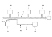
図1に示すように、本実施形態に係るワイヤハーネス構造は、標準ハーネス11と、追加接続ハーネス12と、コネクタ装置13とを備えている。
As shown in FIG. 1, the wire harness structure according to this embodiment includes a
標準ハーネス11は、通信線、電源線、アース線等を有する電線束21を備えている。この標準ハーネス11は、例えば、車体のフロアに沿ってほぼ中央部に配索され、車体1の背骨(バックボーン)のような単純な形状とされている。この標準ハーネス11は、例えば、エアコン・ユニットやパワーウインド・ユニットなどの車両に共通して取り付けられる標準電装機器26を備えている。
The
この標準ハーネス11には、電線束21に、多重通信分配コネクタ22と、電源分配コネクタ23と、アース分配コネクタ24とが設けられている。これらの多重通信分配コネクタ22、電源分配コネクタ23及びアース分配コネクタ24は、それぞれジョイントコネクタから構成されている。多重通信分配コネクタ22には、電子制御ユニット(ECU:Electronic Control Unit)から延びる通信線に設けらされたコネクタが接合される。電源分配コネクタ23には、バッテリなどの電源から延びる電源線に設けられたコネクタが接合される。また、アース分配コネクタ24には、車体のボディなどに接続されて接地されたアース線に設けられたコネクタが接合される。これにより、標準ハーネス11では、標準電装機器26に対する電力供給、標準電装機器26と電子制御ユニットとの通信が可能となり、標準電装機器26の駆動及び制御が可能とされている。
In the
標準ハーネス11には、電線束21の端部に、標準コネクタ25が接続されており、この標準コネクタ25は、コネクタ装置13に接合される。
A
追加接続ハーネス12は、通信線、電源線、アース線等を有する電線束31を備えている。追加接続ハーネス12は、その一端側に追加電装機器32が接続されている。この追加電装機器32は、車両に共通して取り付けられる標準電装機器26に加えて、車両に選択的に後付けされる電装機器である。追加電装機器32は、例えば、ヘッドアップディスプレイ(HUD:Head Up Display)、車載カメラ、ミリ波レーダーなどの電装機器である。追加接続ハーネス12は、グレードに応じて各種の追加電装機器32を備えたものが車両に搭載される。
The
この追加接続ハーネス12は、その他端に、追加接続コネクタ33が接続されており、この追加接続コネクタ33は、コネクタ装置13に接合される。
An
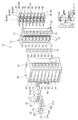
図2は、コネクタ装置の分解斜視図である。図3は、標準コネクタ、追加接続コネクタ及びダミーコネクタが接合されたコネクタ装置の斜視図である。 FIG. 2 is an exploded perspective view of the connector device. FIG. 3 is a perspective view of a connector device in which a standard connector, an additional connection connector, and a dummy connector are joined.
図2及び図3に示すように、コネクタ装置13は、複数(本例では8個)のスロット41を有しており、これらのスロット41に、標準コネクタ25及び追加接続コネクタ33が接合される。
As shown in FIGS. 2 and 3, the
標準コネクタ25に接続される標準ハーネス11の電線束21は、本例では、一本の電源線21A、一本のアース線21B及び二本の通信線21C,21Dを有している。また、追加接続コネクタ33に接続される追加接続ハーネス12の電線束31は、本例では、一本の電源線31A、一本のアース線31B及び二本の通信線31C,31Dを有している。
In this example, the
標準コネクタ25及び追加接続コネクタ33は、それぞれハウジング51と複数のメス端子52とを有している。ハウジング51は、樹脂成形品であり、複数の端子収容部53を有している。これらの端子収容部53には、ハウジング51の後端側からメス端子52が挿し込まれて収容される。なお、ハウジング51の前端には、端子収容部53と連通するタブ挿入孔(図示略)が形成されている。メス端子52は、銅または銅合金等の導電性金属材料から形成されている。メス端子52は、圧着部55と電気接続部56とを有している。電気接続部56は、筒状に形成されており、その内部に後述するバスバー90のタブ部92が挿し込まれる。
The
標準コネクタ25では、メス端子52が、電源線21A、アース線21B及び通信線21C,21Dの端部にそれぞれ圧着部55が圧着されて電気的に接続されており、それぞれのメス端子52がハウジング51の端子収容部53に挿し込まれて収容されている。
In the
追加接続コネクタ33では、メス端子52が、電源線31A、アース線31B及び通信線31C,31Dの端部にそれぞれ圧着部55が圧着されて電気的に接続されており、それぞれのメス端子52がハウジング51の端子収容部53に挿し込まれて収容されている。
In the
また、コネクタ装置13には、標準コネクタ25及び追加接続コネクタ33が接合されたスロット41以外の空きスロット41に、ダミーコネクタ40が接合されている。このダミーコネクタ40は、標準コネクタ25及び追加接続コネクタ33と同一のハウジング51からなるものである。なお、このダミーコネクタ40のハウジング51は、メス端子52を備えていてもよく、また、メス端子52を備えていなくてもよい。また、ダミーコネクタ40としては、空きスロット41を塞ぐための、例えば、端子収容部53のない専用のハウジングからなるものでもよい。
In the
コネクタ装置13は、ハウジング本体60と、インナーハウジング70と、ノイズ抑制部材80と、バスバー90とを備えている。
The
ハウジング本体60は、樹脂成形品であり、箱型に形成されている。このハウジング本体60には、その前面側に、複数のスロット41が上下方向に並列に形成されている。ハウジング本体60は、その後面側に、嵌合凹部(図示略)が形成されている。また、ハウジング本体60の後部における上下には、爪部(図示略)を有するロック部61が形成されている。
The
さらに、ハウジング本体60には、一側部に、取付部62が形成されている。この取付部62は、ハウジング本体60の前後方向に形成された溝部63を有している。また、取付部62は、係止片部64を有している。この係止片部64は、ハウジング本体60の側面との間に隙間をあけて溝部63を跨ぐように形成されている。この取付部62には、車体側に設けられた板状のブラケット(図示略)が溝部63に入れられ、ハウジング本体60の側面と係止片部64との間に挿し込まれる。これにより、ハウジング本体60が車体の所定位置に取り付けられる。
Further, the
インナーハウジング70は、ハウジング本体60と同様に樹脂成形品である。このインナーハウジング70は、ハウジング本体60の後面側に形成された嵌合凹部に嵌合されてハウジング本体60に装着される。インナーハウジング70は、上下にロック係止部71を有しており、ハウジング本体60の嵌合凹部に嵌合させた際に、ロック係止部71がハウジング本体60のロック部61によって係止される。これにより、インナーハウジング70がハウジング本体60に装着された状態に維持される。
The
インナーハウジング70は、ハウジング本体60への装着側に、複数の仕切り壁75によって区画された複数のコネクタ接合部72を有している。これらのコネクタ接合部72は、ハウジング本体60の各スロット41に対応する位置に設けられている。コネクタ接合部72には、表裏に貫通する四つ(図2ではそれぞれ二つを図示)のタブ挿通孔73が間隔をあけて形成されている。また、コネクタ接合部72には、その幅方向の中央に、収容凹部74が形成されている。タブ挿通孔73のうちの中央寄りの二つのタブ挿通孔73は、収容凹部74内に形成されている。
The
ノイズ抑制部材80は、例えば、フェライトから成形されたもので、ハウジング本体60のスロット41と同数(8個)設けられている。ノイズ抑制部材80は、インナーハウジング70の各コネクタ接合部72の収容凹部74に嵌合されて収容される。ノイズ抑制部材80には、二つの貫通孔81が形成されている。ノイズ抑制部材80は、収容凹部74に収容された状態で、貫通孔81がインナーハウジング70のタブ挿通孔73と連通される。
The
バスバー90は、銅または銅合金等の導電性金属材料から形成されている。本例では、4本のバスバー90を備えている。バスバー90は、長尺の板状に形成されたバスバー本体91と、このバスバー本体91の一側部に形成された複数の棒状のタブ部92とを有している。これらのタブ部92は、ハウジング本体60のスロット41と同数(8本)形成されており、互いに間隔をあけて平行に延在されている。また、バスバー本体91の両端には、係止突起93が形成されている。
The bus bar 90 is made of a conductive metal material such as copper or a copper alloy. In this example, four bus bars 90 are provided. The bus bar 90 includes a bus bar
バスバー90は、インナーハウジング70に対して、ハウジング本体60への装着側と反対側である後面側から装着される。バスバー90は、インナーハウジング70に対して上下方向に配置されており、それぞれインナーハウジング70の幅方向に間隔をあけて並列に配置されている。これらのバスバー90は、そのタブ部92がインナーハウジング70のタブ挿通孔73に挿し込まれてインナーハウジング70に装着される。
The bus bar 90 is attached to the
各バスバー90は、インナーハウジング70に装着されることで、係止突起93がインナーハウジング70に係止され、これにより、インナーハウジング70に装着された状態に維持される。また、バスバー90は、インナーハウジング70に装着することで、タブ部92がインナーハウジング70のコネクタ接合部72から突出される。このとき、インナーハウジング70の中央寄りに装着される二つのバスバー90のタブ部92は、収容凹部74に収容されたノイズ抑制部材80の貫通孔81に通されて突出される。
Each bus bar 90 is attached to the
ここで、インナーハウジング70の両側寄りに装着されるバスバー90は、一方が電源用バスバー90Aとされ、他方がアース用バスバー90Bとされている。また、インナーハウジング70の中央寄りに装着される二つのバスバー90は、通信用バスバー90C,90Dとされている。
Here, one of the bus bars 90 mounted on both sides of the
コネクタ装置13では、ハウジング本体60に対して、ノイズ抑制部材80及びバスバー90が装着されたインナーハウジング70を後方側から嵌合凹部に嵌め込んで装着すると、バスバー90のタブ部92がハウジング本体60のスロット41内に収容される。
In the
上記のコネクタ装置13を備えたワイヤハーネス構造では、標準ハーネス11を車両の車体に配索する。そして、この標準ハーネス11の標準コネクタ25を、車体の所定位置に取り付けられたコネクタ装置13のスロット41に接合する。さらに、車両に追加電装機器32を後付けする際には、追加電装機器32が接続された追加接続ハーネス12を車体に配索する。そして、この追加接続ハーネス12の追加接続コネクタ33を、コネクタ装置13のスロット41に接合する。
In the wire harness structure provided with the
このように、標準ハーネス11の標準コネクタ25が接合されたコネクタ装置13に追加接続ハーネス12の追加接続コネクタ33を接合すると、標準コネクタ25及び追加接続コネクタ33のメス端子52の電気接続部56に、バスバー90のタブ部92が挿し込まれ、メス端子52とバスバー90とが電気的に接続される。これにより、標準ハーネス11の電線束21の電源線21A、アース線21B及び通信線21C,21Dと、追加接続ハーネス12の電線束31の電源線31A、アース線31B及び通信線31C,31Dとが、電源用バスバー90A、アース用バスバー90B及び通信用バスバー90C,90Dを介して互いに電気的に接続される。
As described above, when the
これにより、標準ハーネス11に接続された電源、電子制御ユニット及びアースが追加接続ハーネス12にもつなげられ、追加電装機器32に対する電力供給、追加電装機器32と電子制御ユニットとの通信が可能となり、追加電装機器32の駆動及び制御が可能となる。
As a result, the power source, the electronic control unit, and the ground connected to the
以上、説明したように、本実施形態に係るワイヤハーネス構造によれば、標準ハーネス11の標準コネクタ25がスロット41に接合されたコネクタ装置13の他のスロット41に追加接続ハーネス12の追加接続コネクタ33を接合することで、標準電装機器26を備えた標準ハーネス11に対して追加電装機器32を備えた追加接続ハーネス12を一括集中的に追加接続することができる。
As described above, according to the wire harness structure according to the present embodiment, the additional connection connector of the
したがって、圧接、接着あるいは溶着などの煩雑な接続作業を行うことなく、オプション装備の追加、量産後の装備の追加を容易に行うことができる。 Accordingly, it is possible to easily add optional equipment and equipment after mass production without performing complicated connection work such as pressure welding, adhesion, or welding.
これにより、車両のグレードの違いによる搭載装備の差をコネクタ装置13で吸収することができ、各種の車両における標準電装機器26を備えた標準ハーネス11の品番の共通化を図ることができる。
Thereby, the difference of the mounting equipment by the difference in the grade of a vehicle can be absorbed with the
また、コネクタ装置13から追加接続コネクタ33を外すことで、一旦追加した追加電装機器32を容易に取り外すことができる。これにより、ハーネスの補修や交換が必要となる圧接、接着あるいは溶着などで追加電装機器32を接続する場合と比較し、ハーネスの補修や交換にかかるコストを削減できる。
Moreover, the additional
また、コネクタ装置13は、標準ハーネス11の電源線21A、アース線21B及び通信線21C,21Dと、追加接続ハーネス12の電源線31A、アース線31B及び通信線31C,31Dとを電源用バスバー90A、アース用バスバー90B及び通信用バスバー90C,90Dによって電気的に接続するものであり、標準電装機器26及び追加電装機器32を制御するための制御部を備えたものと比較して小型化を図ることができる。
The
また、コネクタ装置13では、標準コネクタ25及び追加接続コネクタ33が接合されていない空きスロット41にダミーコネクタ40が接合されることで、空きスロット41を保護することができる。具体的には、空きスロット41内に突出されたバスバー90のタブ部92の保護及びタブ部92間の絶縁の確保等が可能である。
In the
また、コネクタ装置13には、通信用バスバー90C,90Dの各タブ部92からのノイズの発生を抑制するフェライトからなるノイズ抑制部材80が設けられているので、このノイズ抑制部材80によって複数の通信用バスバー90C,90D同士のノイズによる影響を極力抑制することができる。
Further, since the
尚、本発明は、上述した実施形態に限定されるものではなく、適宜、変形、改良、等が可能である。その他、上述した実施形態における各構成要素の材質、形状、寸法、数、配置箇所、等は本発明を達成できるものであれば任意であり、限定されない。 In addition, this invention is not limited to embodiment mentioned above, A deformation | transformation, improvement, etc. are possible suitably. In addition, the material, shape, dimensions, number, arrangement location, and the like of each component in the above-described embodiment are arbitrary and are not limited as long as the present invention can be achieved.
例えば、車両に標準的に配索される他のワイヤハーネスのコネクタをコネクタ装置13のスロット41に接合させて電源線、アース線及び通信線同士を接続し、ハーネス間における電源、アース及び通信回路の共通化を図ることも可能である。
For example, a connector of another wire harness that is normally routed in a vehicle is joined to the
ここで、上述した本発明に係るワイヤハーネス構造の実施形態の特徴をそれぞれ以下[1]〜[3]に簡潔に纏めて列記する。
[1] 標準電装機器(26)及び標準コネクタ(25)が設けられた標準ハーネス(11)と、
追加電装機器(32)及び追加接続コネクタ(33)が設けられた追加接続ハーネス(12)と、
前記標準コネクタ(25)及び前記追加接続コネクタ(33)が接合可能な複数のスロット(41)を有するコネクタ装置(13)と、
からなる車両用のワイヤハーネス構造であって、
前記標準ハーネス(11)及び前記追加接続ハーネス(12)は、それぞれ少なくとも電源線(21A,31A)、アース線(21B,31B)及び通信線(21C,21D,31C,31D)を有し、
前記コネクタ装置(13)は、前記スロット(41)に前記標準コネクタ(25)及び前記追加接続コネクタ(33)が接合されることで、前記標準ハーネス(11)及び前記追加接続ハーネス(12)の前記(21A,31A)、アース線(21B,31B)及び通信線(21C,21D,31C,31D)同士を電気的に接続する電源用バスバー(90A)、アース用バスバー(90B)及び通信用バスバー(90C,90D)を備える
ことを特徴とするワイヤハーネス構造。
[2] 前記コネクタ装置(13)における前記標準コネクタ(25)及び前記追加接続コネクタ(33)が接合されていない前記スロット(41)には、ダミーコネクタ(40)が接合されている
ことを特徴とする[1]に記載のワイヤハーネス構造。
[3] 前記標準ハーネス(11)及び前記追加接続ハーネス(12)は、それぞれ複数の前記通信線(21C,21D,31C,31D)を有し、
前記コネクタ装置(13)は、複数の前記通信線(21C,21D,31C,31D)同士を電気的に接続する複数の前記通信用バスバー(90C,90D)を備え、
前記コネクタ装置(13)には、前記通信用バスバー(90C,90D)からのノイズの発生を抑制するノイズ抑制部材(80)が設けられている
ことを特徴とする[1]または[2]に記載のワイヤハーネス構造。
Here, the features of the embodiment of the wire harness structure according to the present invention described above are briefly summarized and listed in the following [1] to [3], respectively.
[1] A standard harness (11) provided with a standard electrical equipment (26) and a standard connector (25);
An additional connection harness (12) provided with an additional electrical equipment (32) and an additional connection connector (33);
A connector device (13) having a plurality of slots (41) to which the standard connector (25) and the additional connection connector (33) can be joined;
A wire harness structure for a vehicle comprising:
The standard harness (11) and the additional connection harness (12) have at least a power line (21A, 31A), a ground line (21B, 31B), and a communication line (21C, 21D, 31C, 31D), respectively.
In the connector device (13), the standard connector (25) and the additional connection connector (33) are joined to the slot (41), whereby the standard harness (11) and the additional connection harness (12). The power bus bar (90A), the ground bus bar (90B), and the communication bus bar that electrically connect the (21A, 31A), the ground wire (21B, 31B) and the communication wire (21C, 21D, 31C, 31D). (90C, 90D) The wire harness structure characterized by the above-mentioned.
[2] A dummy connector (40) is joined to the slot (41) in which the standard connector (25) and the additional connection connector (33) are not joined in the connector device (13). The wire harness structure according to [1].
[3] The standard harness (11) and the additional connection harness (12) each have a plurality of the communication lines (21C, 21D, 31C, 31D),
The connector device (13) includes a plurality of communication bus bars (90C, 90D) for electrically connecting the plurality of communication lines (21C, 21D, 31C, 31D) to each other,
[1] or [2], wherein the connector device (13) is provided with a noise suppression member (80) that suppresses generation of noise from the communication bus bar (90C, 90D). The described wire harness structure.
11:標準ハーネス
12:追加接続ハーネス
13:コネクタ装置
21A,31A:電源線
21B,31B:アース線
21C,21D,31C,31D:通信線
25:標準コネクタ
26:標準電装機器
32:追加電装機器
33:追加接続コネクタ
40:ダミーコネクタ
41:スロット
80:ノイズ抑制部材
90A:電源用バスバー
90B:アース用バスバー
90C,90D:通信用バスバー
11: Standard harness 12: Additional connection harness 13:
Claims (3)
追加電装機器及び追加接続コネクタが設けられた追加接続ハーネスと、
前記標準コネクタ及び前記追加接続コネクタが接合可能な複数のスロットを有するコネクタ装置と、
からなる車両用のワイヤハーネス構造であって、
前記標準ハーネス及び前記追加接続ハーネスは、それぞれ少なくとも電源線、アース線及び通信線を有し、
前記コネクタ装置は、前記スロットに前記標準コネクタ及び前記追加接続コネクタが接合されることで、前記標準ハーネス及び前記追加接続ハーネスの前記アース線及び通信線同士を電気的に接続する電源用バスバー、アース用バスバー及び通信用バスバーを備える
ことを特徴とするワイヤハーネス構造。 Standard harness with standard electrical equipment and standard connectors,
An additional connection harness provided with additional electrical equipment and an additional connection connector;
A connector device having a plurality of slots to which the standard connector and the additional connector can be joined; and
A wire harness structure for a vehicle comprising:
The standard harness and the additional connection harness each have at least a power line, a ground line, and a communication line,
In the connector device, the standard connector and the additional connection connector are joined to the slot, so that the ground wire and the communication line of the standard harness and the additional connection harness are electrically connected to each other. A wire harness structure comprising a bus bar for communication and a bus bar for communication.
ことを特徴とする請求項1に記載のワイヤハーネス構造。 The wire harness structure according to claim 1, wherein a dummy connector is joined to the slot in which the standard connector and the additional connection connector in the connector device are not joined.
前記コネクタ装置は、複数の前記通信線同士を電気的に接続する複数の前記通信用バスバーを備え、
前記コネクタ装置には、前記通信用バスバーからのノイズの発生を抑制するノイズ抑制部材が設けられている
ことを特徴とする請求項1または請求項2に記載のワイヤハーネス構造。 Each of the standard harness and the additional connection harness includes a plurality of the communication lines,
The connector device includes a plurality of the communication bus bars that electrically connect the plurality of communication lines.
The wire harness structure according to claim 1, wherein the connector device is provided with a noise suppression member that suppresses generation of noise from the communication bus bar.
Priority Applications (1)
| Application Number | Priority Date | Filing Date | Title |
|---|---|---|---|
| JP2016236744A JP2018092837A (en) | 2016-12-06 | 2016-12-06 | Wire harness structure |
Applications Claiming Priority (1)
| Application Number | Priority Date | Filing Date | Title |
|---|---|---|---|
| JP2016236744A JP2018092837A (en) | 2016-12-06 | 2016-12-06 | Wire harness structure |
Publications (1)
| Publication Number | Publication Date |
|---|---|
| JP2018092837A true JP2018092837A (en) | 2018-06-14 |
Family
ID=62563798
Family Applications (1)
| Application Number | Title | Priority Date | Filing Date |
|---|---|---|---|
| JP2016236744A Abandoned JP2018092837A (en) | 2016-12-06 | 2016-12-06 | Wire harness structure |
Country Status (1)
| Country | Link |
|---|---|
| JP (1) | JP2018092837A (en) |
Citations (3)
| Publication number | Priority date | Publication date | Assignee | Title |
|---|---|---|---|---|
| JP2004080918A (en) * | 2002-08-19 | 2004-03-11 | Sumitomo Wiring Syst Ltd | Electrical connection box, and method of assembling this electrical connection box |
| JP2009146603A (en) * | 2007-12-11 | 2009-07-02 | Sumitomo Wiring Syst Ltd | Connector |
| JP2010033958A (en) * | 2008-07-30 | 2010-02-12 | Autonetworks Technologies Ltd | Branch connector and communication line having the branch connector |
-
2016
- 2016-12-06 JP JP2016236744A patent/JP2018092837A/en not_active Abandoned
Patent Citations (3)
| Publication number | Priority date | Publication date | Assignee | Title |
|---|---|---|---|---|
| JP2004080918A (en) * | 2002-08-19 | 2004-03-11 | Sumitomo Wiring Syst Ltd | Electrical connection box, and method of assembling this electrical connection box |
| JP2009146603A (en) * | 2007-12-11 | 2009-07-02 | Sumitomo Wiring Syst Ltd | Connector |
| JP2010033958A (en) * | 2008-07-30 | 2010-02-12 | Autonetworks Technologies Ltd | Branch connector and communication line having the branch connector |
Similar Documents
| Publication | Publication Date | Title |
|---|---|---|
| JP5130110B2 (en) | Electrical junction box | |
| JP5875115B2 (en) | Electrical junction box | |
| US10525906B2 (en) | Branch structure and wire harness | |
| US10882476B2 (en) | Vehicular circuit body | |
| EP2405729B1 (en) | Connector cover and junction box unit provided with the same | |
| US9148964B2 (en) | Electrical junction box | |
| US8804314B2 (en) | Electric junction box | |
| US11146020B2 (en) | Wire harness including a connector holder | |
| JP2020058182A (en) | Wiring harness | |
| JP6842451B2 (en) | Wire harness | |
| US11052837B2 (en) | Wire harness | |
| CA2930710C (en) | Electronic corrosion protection device | |
| JP5156499B2 (en) | Electrical junction box | |
| JP2006296172A (en) | Electric connection box | |
| JP2018092837A (en) | Wire harness structure | |
| JP7168533B2 (en) | wire harness | |
| JP4809733B2 (en) | Substrate unit, manufacturing method thereof, and electrical junction box | |
| US20200101909A1 (en) | Wire harness system | |
| JP2014220864A (en) | Electric wiring block having electric component | |
| JP5088946B2 (en) | Junction box | |
| JP2013149501A (en) | Connector | |
| EP2909897B1 (en) | Pluggable electrical potential-distribution fuse-adapter | |
| JP6585426B2 (en) | Electrical junction box and wire harness | |
| JP2009266603A (en) | Grounding joint connector | |
| JP2012157094A (en) | Switch box |
Legal Events
| Date | Code | Title | Description |
|---|---|---|---|
| A621 | Written request for application examination |
Free format text: JAPANESE INTERMEDIATE CODE: A621 Effective date: 20191119 |
|
| A977 | Report on retrieval |
Free format text: JAPANESE INTERMEDIATE CODE: A971007 Effective date: 20201019 |
|
| A131 | Notification of reasons for refusal |
Free format text: JAPANESE INTERMEDIATE CODE: A131 Effective date: 20201027 |
|
| A762 | Written abandonment of application |
Free format text: JAPANESE INTERMEDIATE CODE: A762 Effective date: 20201218 |