JP2018091277A - Handheld engine work machine - Google Patents
Handheld engine work machine Download PDFInfo
- Publication number
- JP2018091277A JP2018091277A JP2016236903A JP2016236903A JP2018091277A JP 2018091277 A JP2018091277 A JP 2018091277A JP 2016236903 A JP2016236903 A JP 2016236903A JP 2016236903 A JP2016236903 A JP 2016236903A JP 2018091277 A JP2018091277 A JP 2018091277A
- Authority
- JP
- Japan
- Prior art keywords
- work
- speed range
- mode
- ignition timing
- normal mode
- Prior art date
- Legal status (The legal status is an assumption and is not a legal conclusion. Google has not performed a legal analysis and makes no representation as to the accuracy of the status listed.)
- Pending
Links
Images


Classifications
-
- F—MECHANICAL ENGINEERING; LIGHTING; HEATING; WEAPONS; BLASTING
- F02—COMBUSTION ENGINES; HOT-GAS OR COMBUSTION-PRODUCT ENGINE PLANTS
- F02P—IGNITION, OTHER THAN COMPRESSION IGNITION, FOR INTERNAL-COMBUSTION ENGINES; TESTING OF IGNITION TIMING IN COMPRESSION-IGNITION ENGINES
- F02P5/00—Advancing or retarding ignition; Control therefor
- F02P5/04—Advancing or retarding ignition; Control therefor automatically, as a function of the working conditions of the engine or vehicle or of the atmospheric conditions
- F02P5/05—Advancing or retarding ignition; Control therefor automatically, as a function of the working conditions of the engine or vehicle or of the atmospheric conditions using mechanical means
- F02P5/06—Advancing or retarding ignition; Control therefor automatically, as a function of the working conditions of the engine or vehicle or of the atmospheric conditions using mechanical means dependent on engine speed
-
- F—MECHANICAL ENGINEERING; LIGHTING; HEATING; WEAPONS; BLASTING
- F02—COMBUSTION ENGINES; HOT-GAS OR COMBUSTION-PRODUCT ENGINE PLANTS
- F02B—INTERNAL-COMBUSTION PISTON ENGINES; COMBUSTION ENGINES IN GENERAL
- F02B63/00—Adaptations of engines for driving pumps, hand-held tools or electric generators; Portable combinations of engines with engine-driven devices
- F02B63/02—Adaptations of engines for driving pumps, hand-held tools or electric generators; Portable combinations of engines with engine-driven devices for hand-held tools
-
- F—MECHANICAL ENGINEERING; LIGHTING; HEATING; WEAPONS; BLASTING
- F02—COMBUSTION ENGINES; HOT-GAS OR COMBUSTION-PRODUCT ENGINE PLANTS
- F02P—IGNITION, OTHER THAN COMPRESSION IGNITION, FOR INTERNAL-COMBUSTION ENGINES; TESTING OF IGNITION TIMING IN COMPRESSION-IGNITION ENGINES
- F02P1/00—Installations having electric ignition energy generated by magneto- or dynamo- electric generators without subsequent storage
- F02P1/005—Construction and fastening of elements of magnetos other than the magnetic circuit and the windings
-
- F—MECHANICAL ENGINEERING; LIGHTING; HEATING; WEAPONS; BLASTING
- F02—COMBUSTION ENGINES; HOT-GAS OR COMBUSTION-PRODUCT ENGINE PLANTS
- F02P—IGNITION, OTHER THAN COMPRESSION IGNITION, FOR INTERNAL-COMBUSTION ENGINES; TESTING OF IGNITION TIMING IN COMPRESSION-IGNITION ENGINES
- F02P1/00—Installations having electric ignition energy generated by magneto- or dynamo- electric generators without subsequent storage
- F02P1/08—Layout of circuits
-
- F—MECHANICAL ENGINEERING; LIGHTING; HEATING; WEAPONS; BLASTING
- F02—COMBUSTION ENGINES; HOT-GAS OR COMBUSTION-PRODUCT ENGINE PLANTS
- F02P—IGNITION, OTHER THAN COMPRESSION IGNITION, FOR INTERNAL-COMBUSTION ENGINES; TESTING OF IGNITION TIMING IN COMPRESSION-IGNITION ENGINES
- F02P5/00—Advancing or retarding ignition; Control therefor
- F02P5/005—Advancing or retarding ignition; Control therefor with combination of automatic and non- automatic means
-
- F—MECHANICAL ENGINEERING; LIGHTING; HEATING; WEAPONS; BLASTING
- F02—COMBUSTION ENGINES; HOT-GAS OR COMBUSTION-PRODUCT ENGINE PLANTS
- F02P—IGNITION, OTHER THAN COMPRESSION IGNITION, FOR INTERNAL-COMBUSTION ENGINES; TESTING OF IGNITION TIMING IN COMPRESSION-IGNITION ENGINES
- F02P5/00—Advancing or retarding ignition; Control therefor
- F02P5/02—Advancing or retarding ignition; Control therefor non-automatically; dependent on position of personal controls of engine, e.g. throttle position
-
- F—MECHANICAL ENGINEERING; LIGHTING; HEATING; WEAPONS; BLASTING
- F02—COMBUSTION ENGINES; HOT-GAS OR COMBUSTION-PRODUCT ENGINE PLANTS
- F02P—IGNITION, OTHER THAN COMPRESSION IGNITION, FOR INTERNAL-COMBUSTION ENGINES; TESTING OF IGNITION TIMING IN COMPRESSION-IGNITION ENGINES
- F02P5/00—Advancing or retarding ignition; Control therefor
- F02P5/04—Advancing or retarding ignition; Control therefor automatically, as a function of the working conditions of the engine or vehicle or of the atmospheric conditions
- F02P5/145—Advancing or retarding ignition; Control therefor automatically, as a function of the working conditions of the engine or vehicle or of the atmospheric conditions using electrical means
- F02P5/15—Digital data processing
- F02P5/1502—Digital data processing using one central computing unit
- F02P5/1504—Digital data processing using one central computing unit with particular means during a transient phase, e.g. acceleration, deceleration, gear change
-
- F—MECHANICAL ENGINEERING; LIGHTING; HEATING; WEAPONS; BLASTING
- F02—COMBUSTION ENGINES; HOT-GAS OR COMBUSTION-PRODUCT ENGINE PLANTS
- F02B—INTERNAL-COMBUSTION PISTON ENGINES; COMBUSTION ENGINES IN GENERAL
- F02B75/00—Other engines
- F02B75/02—Engines characterised by their cycles, e.g. six-stroke
- F02B2075/022—Engines characterised by their cycles, e.g. six-stroke having less than six strokes per cycle
- F02B2075/025—Engines characterised by their cycles, e.g. six-stroke having less than six strokes per cycle two
-
- F—MECHANICAL ENGINEERING; LIGHTING; HEATING; WEAPONS; BLASTING
- F02—COMBUSTION ENGINES; HOT-GAS OR COMBUSTION-PRODUCT ENGINE PLANTS
- F02D—CONTROLLING COMBUSTION ENGINES
- F02D2400/00—Control systems adapted for specific engine types; Special features of engine control systems not otherwise provided for; Power supply, connectors or cabling for engine control systems
- F02D2400/06—Small engines with electronic control, e.g. for hand held tools
-
- F—MECHANICAL ENGINEERING; LIGHTING; HEATING; WEAPONS; BLASTING
- F02—COMBUSTION ENGINES; HOT-GAS OR COMBUSTION-PRODUCT ENGINE PLANTS
- F02P—IGNITION, OTHER THAN COMPRESSION IGNITION, FOR INTERNAL-COMBUSTION ENGINES; TESTING OF IGNITION TIMING IN COMPRESSION-IGNITION ENGINES
- F02P1/00—Installations having electric ignition energy generated by magneto- or dynamo- electric generators without subsequent storage
- F02P1/08—Layout of circuits
- F02P1/086—Layout of circuits for generating sparks by discharging a capacitor into a coil circuit
-
- Y—GENERAL TAGGING OF NEW TECHNOLOGICAL DEVELOPMENTS; GENERAL TAGGING OF CROSS-SECTIONAL TECHNOLOGIES SPANNING OVER SEVERAL SECTIONS OF THE IPC; TECHNICAL SUBJECTS COVERED BY FORMER USPC CROSS-REFERENCE ART COLLECTIONS [XRACs] AND DIGESTS
- Y02—TECHNOLOGIES OR APPLICATIONS FOR MITIGATION OR ADAPTATION AGAINST CLIMATE CHANGE
- Y02T—CLIMATE CHANGE MITIGATION TECHNOLOGIES RELATED TO TRANSPORTATION
- Y02T10/00—Road transport of goods or passengers
- Y02T10/10—Internal combustion engine [ICE] based vehicles
- Y02T10/40—Engine management systems
Landscapes
- Engineering & Computer Science (AREA)
- Chemical & Material Sciences (AREA)
- Combustion & Propulsion (AREA)
- Mechanical Engineering (AREA)
- General Engineering & Computer Science (AREA)
- Theoretical Computer Science (AREA)
- Signal Processing (AREA)
- Electrical Control Of Ignition Timing (AREA)
- Combined Controls Of Internal Combustion Engines (AREA)
- Ignition Installations For Internal Combustion Engines (AREA)
Abstract
Description
本発明は、手持ち式エンジン作業機に関し、更に詳細には、チェーンソー、刈払機、エンジンカッター、ヘッジトリマー等の手持ち式エンジン作業機に関する。 The present invention relates to a hand-held engine working machine, and more particularly to a hand-held engine working machine such as a chain saw, a brush cutter, an engine cutter, a hedge trimmer, and the like.
手持ち式エンジン作業機に搭載された2サイクル内燃エンジンは、シリンダ内に配置され且つクランクシャフトに連結されたピストンと、シリンダの上部に配置された点火プラグと、点火プラグを作動させる点火制御装置を有している。点火プラグの有効な作動により、シリンダ内の混合気を点火して燃焼させ、燃焼空気の膨張により、上死点位置から下死点位置に移動するピストンに力を付与する。点火制御装置は、ピストンの上死点位置に対する点火プラグの点火タイミング(例えば、上死点位置前のクランクシャフトの角度であるBTDC角度)を設定することが可能である。 A two-cycle internal combustion engine mounted on a hand-held engine working machine includes a piston disposed in a cylinder and connected to a crankshaft, a spark plug disposed at an upper portion of the cylinder, and an ignition control device for operating the spark plug. Have. By the effective operation of the spark plug, the air-fuel mixture in the cylinder is ignited and burned, and the expansion of the combustion air applies a force to the piston that moves from the top dead center position to the bottom dead center position. The ignition control device can set the ignition timing of the spark plug with respect to the top dead center position of the piston (for example, the BTDC angle that is the angle of the crankshaft before the top dead center position).
点火制御装置は、通常、低速度範囲(例えば、4000rpm以下)における点火タイミングをピストンの上死点位置に近い第1のBTDC角度A1に設定し、高速度範囲(例えば、9000rpm以上)における点火タイミングを第2のBTDC角度A2まで進角させるように構成される(図13参照)。これは、高速度範囲の出力を向上させるためである。中速度範囲(例えば、4000〜9000rpm)における点火タイミングは、低速度範囲の点火タイミングと高速度範囲の点火タイミングを連続させるように定められている(例えば、特許文献1参照)。 The ignition control device normally sets the ignition timing in the low speed range (for example, 4000 rpm or less) to the first BTDC angle A1 close to the top dead center position of the piston, and the ignition timing in the high speed range (for example, 9000 rpm or more). Is advanced to the second BTDC angle A2 (see FIG. 13). This is to improve the output in the high speed range. The ignition timing in the medium speed range (for example, 4000 to 9000 rpm) is determined so that the ignition timing in the low speed range and the ignition timing in the high speed range are made continuous (for example, see Patent Document 1).
チェーンソーで太い木を切断する場合、一般的に、スロットルレバーを全開位置にして、チェーンソーを高回転速度(例えば、10000rpm)にしてから切断を始める。刃が木に進入していくとエンジンに負荷が掛り、チェーンソーの回転速度が高速度範囲の回転速度よりも低下する。この場合、点火タイミングが第2のBTDC角度A2よりも遅角し、チェーンソーの出力も低下する。 When cutting a thick tree with a chainsaw, generally, the throttle lever is set to a fully open position, and the chain saw is started at a high rotational speed (for example, 10000 rpm). As the blade enters the tree, a load is applied to the engine, and the rotational speed of the chainsaw is lower than the rotational speed in the high speed range. In this case, the ignition timing is retarded from the second BTDC angle A2, and the output of the chainsaw is also reduced.
また、チェーンソーで多くの細い枝を切断する場合、一般的に、スロットルレバーを全開位置にして、チェーンソーを高回転速度(例えば、10000rpm)にして枝を切ることと、1つの枝を切断した後、スロットルレバーを緩めてチェーンソーの回転速度を低下させることを繰返す。回転速度が9000rpmよりも低下すると、点火タイミングが第2のBTDC角度A2よりも遅角して、出力が低下し、次に高回転速度にするときの加速が低下する。 Also, when cutting many thin branches with a chain saw, in general, the throttle lever is in the fully open position, the chain saw is cut at a high rotational speed (for example, 10000 rpm), and after one branch is cut Then, the throttle lever is loosened to repeatedly reduce the rotational speed of the chainsaw. When the rotational speed is lower than 9000 rpm, the ignition timing is retarded from the second BTDC angle A2, the output is decreased, and the acceleration when the rotational speed is subsequently increased is decreased.
仮に、第2のBTDC角度に達する回転速度を6000rpmにすれば(図13参照)、上記出力の低下及び上記加速の低下を解決できそうである。しかしながら、気化器の燃料供給を薄い側に設定したとき、意図しない回転速度の上昇のおそれがある。また、燃料が薄い場合、スロットルレバーを緩めても、回転が低下しにくいことがある。このため、第2のBTDC角度A2に達する回転速度を変更しないことが好ましい。 If the rotational speed at which the second BTDC angle is reached is set to 6000 rpm (see FIG. 13), it is likely that the decrease in the output and the decrease in the acceleration can be solved. However, when the fuel supply of the carburetor is set to the thin side, there is a risk of unintended rotation speed increase. In addition, when the fuel is thin, the rotation may not easily decrease even if the throttle lever is loosened. For this reason, it is preferable not to change the rotational speed that reaches the second BTDC angle A2.
そこで、本発明は、作業中の中速度範囲における上記出力の低下及び上記加速の低下を改善した手持ち式エンジン作業機を提供することを目的とする。 Accordingly, an object of the present invention is to provide a hand-held engine working machine that has improved the reduction in output and the reduction in acceleration in a medium speed range during work.
上記目的を達成するために、本発明による手持ち式のエンジン作業機は、内燃エンジンを有し、前記内燃エンジンは、シリンダと、クランクシャフトと、前記シリンダ内に配置され且つ前記クランクシャフトに連結されたピストンと、前記シリンダの上部に配置された点火プラグを有し、更に、前記点火プラグを作動させる点火制御装置を有し、前記点火制御装置は、中速度範囲において回転速度の上昇とともに点火タイミングを第1のBTDC角度から第2のBTDC角度に進角させ且つ高速度範囲において点火タイミングを前記第2のBTDC角度に維持する通常モードと、高速度範囲において点火タイミングを前記第2のBTDC角度に維持し且つ中速度範囲において点火タイミングを前記第1のBTDC角度と前記第2のBTDC角度の間の第3のBTDC角度よりも進角させる作業モードとの間を切換え可能であり、中速度範囲におけるいずれの回転速度においても、作業モードの点火タイミングは、通常モードの点火タイミングよりも進角されることを特徴としている。 In order to achieve the above object, a hand-held engine working machine according to the present invention includes an internal combustion engine, and the internal combustion engine is disposed in and connected to the cylinder, the crankshaft, and the crankshaft. A spark plug disposed at the top of the cylinder, and further includes an ignition control device for operating the spark plug. The ignition control device has an ignition timing as the rotational speed increases in a medium speed range. Is advanced from the first BTDC angle to the second BTDC angle and the ignition timing is maintained at the second BTDC angle in the high speed range, and the ignition timing is set to the second BTDC angle in the high speed range. And the ignition timing in the medium speed range is the first BTDC angle and the second BTDC angle. The working mode ignition timing is advanced more than the normal mode ignition timing at any rotational speed in the medium speed range. It is characterized by being horned.
このように構成された手持ち式エンジン作業機では、低速度範囲(アイドル運転状態)からスロットレバーを全開位置にして高速度範囲に移行するとき、点火制御装置は、通常モードで作動する。すなわち、点火制御装置は、中速度範囲において回転速度の上昇とともに点火タイミングを第1のBTDC角度から第2のBTDC角度に進角させ且つ高速度範囲において点火タイミングを前記第2のBTDC角度に維持する。一方、点火制御装置が作業モードに切換わった後、高速度範囲において点火タイミングを前記第2のBTDC角度に維持し且つ中速度範囲において点火タイミングを前記第1のBTDC角度と前記第2のBTDC角度の間の第3のBTDC角度よりも進角させ、中速度範囲におけるいずれの回転速度においても、作業モードの点火タイミングは、通常モードの点火タイミングよりも進角される。これにより、中速度範囲において、出力が低下すること及び加速が低下することが防止される。例えば、チェーンソーの刃が木に進入してチェーンソーの回転速度が中速度範囲に低下しても、チェーンソーの出力の低下を軽減することができる。また、チェーンソーで多くの細い枝を切断するために、スロットルレバーを緩めてチェーンソーの回転速度が中速度範囲に低下した後スロットレバーを全開位置にしたとき、チェーンソーの加速を向上させることができる。 In the hand-held engine working machine configured as described above, when the slot lever is fully opened from the low speed range (idle operation state) to shift to the high speed range, the ignition control device operates in the normal mode. That is, the ignition control device advances the ignition timing from the first BTDC angle to the second BTDC angle as the rotational speed increases in the medium speed range, and maintains the ignition timing at the second BTDC angle in the high speed range. To do. On the other hand, after the ignition control device is switched to the work mode, the ignition timing is maintained at the second BTDC angle in the high speed range, and the ignition timing is set to the first BTDC angle and the second BTDC in the medium speed range. The ignition timing in the work mode is advanced more than the ignition timing in the normal mode at any rotational speed in the medium speed range, which is advanced from the third BTDC angle between the angles. This prevents the output from decreasing and the acceleration from decreasing in the medium speed range. For example, even if the chain saw blade enters the tree and the rotation speed of the chain saw falls to the medium speed range, the reduction in the output of the chain saw can be reduced. Further, in order to cut many thin branches with the chainsaw, the acceleration of the chainsaw can be improved when the slot lever is fully opened after the throttle lever is loosened and the rotational speed of the chainsaw is lowered to the middle speed range.
上記手持ち式エンジン作業機の実施形態において、作業モードにおける中速度範囲において、点火タイミングは、前記第2のBTDC角度に維持されてもよいし、回転速度の低下ととともに点火タイミングを前記第2のBTDC角度から進角させ又は遅角させてもよい。 In the embodiment of the hand-held engine working machine, the ignition timing may be maintained at the second BTDC angle in the medium speed range in the working mode, or the ignition timing may be set to the second timing along with a decrease in the rotational speed. The angle may be advanced or retarded from the BTDC angle.
上記手持ち式エンジン作業機の実施形態において、例えば、点火制御装置は、回転速度が所定の作業回転速度よりも小さくなったとき、又は、回転速度が所定の作業回転速度よりも小さくなってから所定の期間の経過後、作業モードを通常モードに切換えるように構成される。 In the above-described embodiment of the hand-held engine work machine, for example, the ignition control device has a predetermined value when the rotation speed becomes lower than the predetermined work rotation speed or after the rotation speed becomes lower than the predetermined work rotation speed. After the elapse of the period, the operation mode is switched to the normal mode.
上記手持ち式エンジン作業機の実施形態において、例えば、点火制御装置は、回転速度が所定の作業回転速度よりも大きくなってから所定の期間の経過後、又は、回転速度が所定の作業回転速度よりも大きくなったとき、通常モードを作業モードに切換えるように構成される。 In the embodiment of the hand-held engine working machine, for example, the ignition control device is configured so that the rotation speed is higher than the predetermined work rotation speed or after a predetermined period has elapsed or the rotation speed is higher than the predetermined work rotation speed. Is configured to switch from the normal mode to the work mode.
上記手持ち式エンジン作業機の実施形態において、例えば、点火制御装置は、スロットルバルブが全開位置にあることを検出したとき、通常モードを作業モードに切換えるように構成される。 In the embodiment of the hand-held engine working machine, for example, the ignition control device is configured to switch the normal mode to the working mode when detecting that the throttle valve is in the fully open position.
上記手持ち式エンジン作業機の実施形態において、例えば、点火制御装置は、スロットルバルブがアイドル位置にないことを検出したとき、通常モードを作業モードに切換えるように構成される。 In the embodiment of the hand-held engine working machine, for example, the ignition control device is configured to switch the normal mode to the working mode when detecting that the throttle valve is not in the idle position.
上記手持ち式エンジン作業機の実施形態において、例えば、点火制御装置は、スロットルバルブが全開位置にないことを検出したとき、又は、スロットルバルブが全開位置にないことを検出してから所定の期間の経過後、又は、スロットルバルブがアイドル位置にあることを検出したとき、作業モードを通常モードに切換えるように構成される。 In the embodiment of the handheld engine working machine, for example, the ignition control device detects that the throttle valve is not in the fully open position, or after detecting that the throttle valve is not in the fully open position, After the elapse of time or when it is detected that the throttle valve is in the idle position, the operation mode is configured to be switched to the normal mode.
本発明による手持ち式エンジン作業機により、作業中の中速度範囲における上記出力の低下及び上記加速の低下を改善することができる。 With the hand-held engine working machine according to the present invention, it is possible to improve the decrease in the output and the decrease in the acceleration in the medium speed range during work.
以下、図面を参照して、本発明によるチェーンソーの実施形態を説明する。 Hereinafter, embodiments of a chain saw according to the present invention will be described with reference to the drawings.
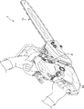
図1は、本発明による手持ち式エンジン作業機の一例であるチェーンソーの斜視図である。チェーンソー1は、それを駆動する2サイクル内燃エンジン2と、内燃エンジン2に流入させる混合気の量を調節するスロットルバルブ3(図2参照)を作動させるスロットルレバー2aを有している。スロットルバルブ3には、必要に応じて、スロットルバルブ3が全開位置にあることを検出するスイッチ3b、又は、スロットルバルブ3がアイドル位置にあることを検出するスイッチ3cが設けられてもよい。
FIG. 1 is a perspective view of a chainsaw as an example of a hand-held engine working machine according to the present invention. The chain saw 1 has a two-cycle
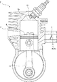
図2は、本発明による2サイクル内燃エンジン2の概略図である。内燃エンジン2は、シリンダ4と、クランクシャフト6と、シリンダ4内に配置され且つクランクシャフト6に連結されたピストン8と、シリンダ4の上部に配置された点火プラグ10を有している。内燃エンジン2の圧縮ストロークにおいて、ピストン8は、上死点位置8aまで上昇する。一般的にはピストン8が上死点位置8aに到達するよりも前のタイミングで、点火プラグ10を有効に作動させてシリンダ4内の混合気を燃焼させることにより、ピストン8に下向きの推進力を与える。
FIG. 2 is a schematic view of a two-cycle
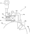
図3は、本発明による内燃エンジンの点火制御装置の概略図である。内燃エンジン2は、点火プラグ10を作動させる点火制御装置12を有する。
FIG. 3 is a schematic diagram of an ignition control device for an internal combustion engine according to the present invention. The
点火制御装置12は、クランクシャフト6に取付けられたフライホイール14aの外周に設けられた1対の磁石14bと、フライホイール14aの外周に隣接して配置されたU字形の鉄心14cと、鉄心14cの周りに巻かれた入力用コイル14dを有している。また、点火制御装置12は、入力用コイル14dに接続された制御回路部16と、制御回路部16に接続された1次側コイル18aと、点火プラグ10に接続された2次側コイル18bを有している。
The
図4は、本発明による内燃エンジン2の点火制御装置12の回路図である。図4に示すように、制御回路部16は、プロセッサ20と、ダイオード22と、コンデンサ24と、スイッチ用サイリスタ26を有する。プロセッサ20のピンaとピンeは、入力用コイル14dに接続され、入力用コイル14dに誘導された電圧は、プロセッサ20に電力を供給する。プロセッサ20のピンb及びピンcも、入力用コイル14dに接続され、プロセッサ20は、入力用コイル14dに誘導された電気信号を受信する。ダイオード22、コンデンサ24及び1次側コイル18aが、入力用コイル14dに直列に接続される。スイッチ用サイリスタ26は、コンデンサ24及び1次側コイル18aと並列に接続される。また、プロセッサ20のピンdは、サイリスタ26のゲートに接続される。ピンdがLOWのとき、サイリスタ26は非通電状態になり、ピンdがHIGHのとき、サイリスタ26は通電状態になる。
FIG. 4 is a circuit diagram of the
次に、本発明による内燃エンジンの作動を説明する。 Next, the operation of the internal combustion engine according to the present invention will be described.
内燃エンジン2の作動により、クランクシャフト6が回転すると、フライホイール14aに取付けられた1対の磁石14bが、U字形鉄心14cの近くを通過する。それにより、入力用コイル14dに電圧が誘導され、入力用コイル14dに電流が流れる。プロセッサ20は、入力用コイル14dからピンa、eを介して供給される電圧によって駆動されるとともに、電流による電気信号をピンb,cを介して受信する。プロセッサ20は、かかる電気信号により、内燃エンジン2の回転速度及び角度位置を検出し又は計算する。
When the
プロセッサ20がピンdをLOWにして、サイリスタ26を非通電状態にすると、入力用コイル14dに誘導された電圧により、コンデンサ24を充電する。点火プラグ10の点火タイミングになったら、プロセッサ20は、ピンdをHIGHにして、サイリスタ26を通電状態にする。それにより、コンデンサ24を放電させて、1次側コイル18aに電流を流す。1次側コイル18aに流れる電流は、2次側コイル18bに高電圧パルスを発生させて、かくして、点火プラグ10を作動させる。
When the processor 20 sets the pin d to LOW and deenergizes the
図5〜図7に例示するように、点火制御装置12のプロセッサ20は、内燃エンジン2の回転速度に応じて設定された点火タイミングで、点火プラグ10を作動させる。本明細書において、点火タイミングを、BTDC角度(上死点位置8a前のクランクシャフト6の角度)で表す。点火タイミングは、2種類のモード、すなわち、実線で示す通常モードと、点線で示す作業モードで作動される。後述するように、通常モードと作業モードは適宜切換えられる。
As illustrated in FIGS. 5 to 7, the processor 20 of the
図5に示す第1の例において、通常モードでは、点火制御装置12は、低速度範囲30(例えば、4000rpm以下)、中速度範囲32(例えば、4000rpm〜9000rpm)、及び高速度範囲34(例えば、9000rpm以上)においてそれぞれ異なる点火タイミングを設定する。低速度範囲30では、点火タイミングを比較的小さい第1のBTDC角度A1に維持する。第1のBTDC角度A1は、ピストン8の上死点位置8a近傍の角度であり、例えば、10〜20度である。高速度範囲34では、点火タイミングを、比較的大きい第2のBTDC角度A2に維持する。第2のBTDC角度A2は、例えば、30〜40度である。中速度範囲32では、回転速度の上昇とともに点火タイミングを第1のBTDC角度A1から第2のBTDC角度A2まで進角させる。
In the first example shown in FIG. 5, in the normal mode, the
作業モードでは、点火制御装置12は、高速度範囲34において、点火タイミングを第2のBTDC角度A2に維持し、中速度範囲32において、点火タイミングを、第1のBTDC角度A1と第2のBTDC角度A2の間の第3のBTDC角度A3よりも遅角させ、中速度範囲32におけるいずれの回転速度においても、作業モードの点火タイミングは、通常モードの点火タイミングよりも遅角される。第1の例では、中速度範囲32において、点火タイミングを、第2のBTDC角度A2に維持する。図5から分かるように、高速度範囲34における点火タイミングは、通常モード及び作業モードにおいて同じであり、中速度範囲32における点火タイミングが、通常モードと作業モードで異なっている。
In the working mode, the
図6に示す第2の例は、第1の例とほとんど同じであるが、作業モードにおける中速度範囲32において、第1の例と異なっている。具体的には、回転速度の低下とともに、点火タイミングを第2のBTDC角度A2から徐々に進角させる。最大の進角量は、例えば、約5〜10度である。作業モードにおける中速度範囲32において、ノッキング生じなければ、第1の例又は第2の例のようにすることが好ましい。
The second example shown in FIG. 6 is almost the same as the first example, but differs from the first example in the
図7に示す第3の例は、第1の例とほとんど同じであるが、作業モードにおける中速度範囲32において、第1の例と異なっている。具体的には、回転速度の低下とともに、点火タイミングを第2のBTDC角度A2から徐々に遅角させる。最大の遅角量は、例えば、約5〜10度である。作業モードにおける中速度範囲32において、ノッキング生じる場合、第3の例のようにすることが好ましい。第3のBTDC角度A3は、回転速度の低下とともに点火タイミングを第2のBTDC角度A2から徐々に遅角させたときに想定される最小のBTDC角度よりも小さい角度である。
The third example shown in FIG. 7 is almost the same as the first example, but differs from the first example in the
次に、図8〜12を参照して、通常モードと作業モードを切換えるフローチャートの5つの例を説明する。これらの例は、図5に示した第1の例の点火タイミングを参照して説明されるが、第2の例(図6)又は第3の例(図7)についても同様である。 Next, five examples of flowcharts for switching between the normal mode and the work mode will be described with reference to FIGS. These examples will be described with reference to the ignition timing of the first example shown in FIG. 5, but the same applies to the second example (FIG. 6) or the third example (FIG. 7).
図8を参照して、通常モードと作業モードを切換えるフローチャートの第1の例を説明する。概略的には、チェーンソー1を通常モードでスタートし、回転速度が第1の作業回転速度S1を越えて適当な期間経過したら、通常モードを作業モードに切換える。また、回転速度が第1の作業回転速度S1よりも低下したら、作業モードを通常モードに切換える。 A first example of a flowchart for switching between the normal mode and the work mode will be described with reference to FIG. In general, the chainsaw 1 is started in the normal mode, and when the rotation speed exceeds the first work rotation speed S1 and an appropriate period of time has elapsed, the normal mode is switched to the work mode. When the rotation speed is lower than the first work rotation speed S1, the work mode is switched to the normal mode.
具体的には、S101において、チェーンソー1を通常モードに設定し、S102において、カウンタをリセットする。スロットルレバー2aによりスロットルバルブ3を開くことにより、回転速度が、低速度範囲30から中速度範囲32に上昇する。S103において、回転速度が中速度範囲32における第1の作業回転速度S1よりも大きいかどうかを判定する。回転速度が第1の作業回転速度S1以下である場合、S102に戻る。回転速度が第1の作業回転速度S1よりも大きい場合、S104において、カウンタの値を1つ増やして、S105において、カウンタの値が所定の値よりも大きいかどうかを判定する。カウンタの値が所定の値以下の場合、すなわち、回転速度が第1の作業回転速度S1を越えて適当な期間が経過していない場合、S103に戻る。カウンタの値が所定の値よりも大きい場合、作業中であると考え、S106において、通常モードを作業モードに切換える。第1の作業回転速度S1は、負荷によって回転速度が高速度範囲34から中速度範囲32に低下しても作業を継続する基準作業回転速度である。例えば、第1の作業回転速度S1は、チェーンソー1の刃1aが木に進入して、回転速度が中速度範囲32に低下しても作業を継続するように定められる。作業モードでは、高速度範囲34だけでなく中速度範囲32においても、点火タイミングが第2のBTDC角度A2に維持されるので、中速度範囲32における出力が増大し、作業を効率よく行うことができる。
Specifically, in S101, the chainsaw 1 is set to the normal mode, and in S102, the counter is reset. When the
次いで、S107において、回転速度が第1の作業回転速度S1よりも小さいかどうかを判定する。回転速度が第1の作業回転速度S1以上である場合、作業を継続していると考え、S107に戻り、作業モードを維持する。回転速度が第1の作業回転速度S1よりも小さい場合、作業を終了したと考え、S108において、作業モードを通常モードに切換える。点火タイミングが、第2のBTDC角度A2よりも小さくなるので、回転速度を中速度範囲32から低速度範囲30に確実に低下させることができる。
Next, in S107, it is determined whether or not the rotational speed is lower than the first work rotational speed S1. When the rotation speed is equal to or higher than the first work rotation speed S1, it is considered that the work is continued, and the process returns to S107 to maintain the work mode. When the rotation speed is lower than the first work rotation speed S1, it is considered that the work is finished, and the work mode is switched to the normal mode in S108. Since the ignition timing is smaller than the second BTDC angle A2, the rotation speed can be reliably lowered from the
次に、図9を参照して、通常モードと作業モードを切換えるフローチャートの第2の例を説明する。概略的には、チェーンソー1を通常モードでスタートし、回転速度が高速度範囲34における第2の作業回転速度S2を越えたら、通常モードを作業モードに切換える。また、回転速度が第3の作業回転速度S3よりも低下して適当な期間経過したら、作業モードを通常モードに切換える。
Next, a second example of a flowchart for switching between the normal mode and the work mode will be described with reference to FIG. In general, the chain saw 1 is started in the normal mode, and when the rotation speed exceeds the second work rotation speed S2 in the
具体的には、S121において、チェーンソー1を通常モードに設定する。スロットルレバー2aによりスロットルバルブ3を開くことにより、回転速度が、低速度範囲30から中速度範囲32を越えて高速度範囲34に上昇する。S122において、回転速度が高速度範囲34における第2の作業回転速度S2よりも大きいかどうかを判定する。回転速度が第2の作業回転速度S2以下の場合、S122に戻る。回転速度が第2の作業回転速度S2よりも大きい場合、S123において、通常モードを作業モードに切換える。作業モードにおいては、例えば、チェーンソー1のスロットルバルブ3を多数の細い枝を切断するために全開と全閉を繰返すように操作するとき、点火タイミングが第2のBTDC角度A2に維持されるので、スロットルバルブ3を全開にしたときの加速性能が向上し、作業を効率よく行うことができる。
Specifically, in S121, the chainsaw 1 is set to the normal mode. By opening the
次いで、S124において、カウンタの値をリセットする。S125において、回転速度が中速度範囲32における第3の作業回転速度S3よりも小さいかどうかを判定する。回転速度が第3の作業回転速度S3以上の場合、S124に戻る。回転速度が第3の作業回転速度S3よりも小さい場合、S126において、カウンタの値を1つ増やして、S127において、カウンタの値が所定の値よりも大きいかどうかを判定する。カウンタの値が所定の値以下の場合、すなわち、回転速度が第3の作業回転速度S3よりも低下して適当な期間が経過していない場合、S125に戻る。カウンタの値が所定の値よりも大きい場合、作業を終了したと考え、S128において、作業モードを通常モードに切換える。第3の作業回転速度S3は、例えば、チェーンソー1のスロットルバルブ3を多数の細い枝を切断するために全開と全閉を繰返すように操作するときに回転速度が中速度範囲32に低下しても作業を継続する基準作業回転速度である。通常モードでは、点火タイミングが、第2のBTDC角度A2よりも小さくなるので、回転速度を中速度範囲32から低速度範囲30に確実に低下させることができる。
Next, in S124, the counter value is reset. In S125, it is determined whether or not the rotation speed is lower than the third work rotation speed S3 in the
次に、図10を参照して、通常モードと作業モードを切換えるフローチャートの第3の例を説明する。この例では、スロットルバルブ3が全開位置にあることを検出するスイッチ3bを使用する。概略的には、チェーンソー1を通常モードでスタートし、スロットルバルブ3が全開位置にあることを検出したら、通常モードを作業モードに切換える。また、スロットルバルブ3が全開位置にないことを検出して適当な期間経過したら、作業モードを通常モードに切換える。
Next, a third example of a flowchart for switching between the normal mode and the work mode will be described with reference to FIG. In this example, a
具体的には、S141において、チェーンソー1を通常モードに設定する。スロットルバルブ3を開くことにより、回転速度が、低速度範囲30から中速度範囲32を越えて高速度範囲34に上昇する。S142において、スロットルバルブ3が全開位置にあるかどうかを判定する。スロットルバルブ3が全開位置にない場合、S142に戻る。スロットルバルブ3が全開位置にある場合、S143において、通常モードを作業モードに切換える。作業モードにおいては、例えば、チェーンソー1のスロットルバルブ3を枝払いのために全開と全閉を繰返すように操作するとき、点火タイミングが第2のBTDC角度A2に維持されるので、スロットルバルブ3を全開にしたときの加速性能が向上し、作業を効率よく行うことができる。
Specifically, in S141, the chainsaw 1 is set to the normal mode. By opening the
次いで、S144において、カウンタの値をリセットする。S145において、スロットルバルブ3が全開位置にあるかどうかを判定する。スロットルバルブが全開位置にある場合、S144に戻る。スロットルバルブが全開位置にない場合、146において、カウンタの値を1つ増やして、S147において、カウンタの値が所定の値よりも大きいかどうかを判定する。カウンタの値が所定の値以下の場合、すなわち、スロットルバルブが全開位置にないけれども再び全開位置にすると予想される適当な期間が経過していない場合、S143に戻る。カウンタの値が所定の値よりも大きい場合、作業を終了したと考え、148において、作業モードを通常モードに切換える。通常モードでは、点火タイミングが、第2のBTDC角度A2よりも小さくなるので、回転速度を中速度範囲32から低速度範囲30に確実に低下させることができる。
In step S144, the counter value is reset. In S145, it is determined whether the
次に、図11を参照して、通常モードと作業モードを切換えるフローチャートの第4の例を説明する。この例では、スロットルバルブが全開位置にあることを検出するスイッチ3bを使用する。概略的には、チェーンソー1を通常モードでスタートし、スロットルバルブ3が全開位置にあることを検出したら、通常モードを作業モードに切換える。また、スロットルバルブ3が全開位置にないことを検出したら、作業モードを通常モードに切換える。
Next, a fourth example of a flowchart for switching between the normal mode and the work mode will be described with reference to FIG. In this example, a
具体的には、S161において、チェーンソー1を通常モードに設定する。スロットルレバー2aによりスロットルバルブ3を開くことにより、回転速度が、低速度範囲30から中速度範囲32を越えて高速度範囲34に上昇する。S162において、スロットルバルブ3が全開位置にあるかどうかを判定する。スロットルバルブ3が全開位置にない場合、通常モードが維持され、S162に戻る。スロットルバルブ3が全開位置にある場合、163において、通常モードを作業モードに切換える。作業モードでは、高速度範囲34だけでなく中速度範囲32においても、点火タイミングが第2のBTDC角度A2に維持されるので、例えば、チェーンソー1の刃1aが木に進入して、回転速度が中速度範囲32に低下しても中速度範囲32における出力が増大し、作業を効率よく行うことができる。
Specifically, in S161, the chainsaw 1 is set to the normal mode. By opening the
次いで、S164において、スロットルバルブ3が全開位置にあるかどうかを判定する。スロットルバルブ3が全開位置にある場合、作業モードが維持され、S164に戻る。スロットルバルブ3が全開位置にない場合、作業を終了したと考え、S165において、通常モードを作業モードに切換える。点火タイミングが、第2のBTDC角度A2よりも小さくなるので、回転速度を中速度範囲32から低速度範囲30に確実に低下させることができる。
Next, in S164, it is determined whether the
次に、図12を参照して、通常モードと作業モードを切換えるフローチャートの第5の例を説明する。概略的には、チェーンソー1を通常モードでスタートし、スロットルバルブ3がアイドル位置にないことを検出したら、通常モードを作業モードに切換える。また、スロットルバルブ3がアイドル位置にあることを検出したら、作業モードを通常モードに切換える。
Next, a fifth example of a flowchart for switching between the normal mode and the work mode will be described with reference to FIG. In general, the chain saw 1 is started in the normal mode, and when it is detected that the
具体的には、S181において、チェーンソー1を通常モードに設定する。S182において、スロットルバルブ3がアイドル位置にあるかどうかを判定する。スロットルバルブ3がアイドル位置にある場合、通常モードが維持され、S182に戻る。スロットルバルブがアイドル位置にない場合、スロットルレバー2aによりスロットルバルブ3を開いており、回転速度が、低速度範囲30から中速度範囲32を越えて高速度範囲34に上昇するので、S183において、通常モードを作業モードに切換える。作業モードでは、高速度範囲34だけでなく中速度範囲32においても、点火タイミングが第2のBTDC角度A2に維持されるので、例えば、チェーンソー1の刃1aが木に進入して、回転速度が中速度範囲32に低下しても中速度範囲32における出力が増大し、作業を効率よく行うことができる。
Specifically, in S181, the chainsaw 1 is set to the normal mode. In S182, it is determined whether the
次いで、S184において、スロットルバルブ3がアイドル位置にあるかどうかを判定する。スロットルバルブ3がアイドル位置にない場合、作業モードが維持され、S184に戻る。スロットルバルブ3がアイドル位置にある場合、作業を終了したと考え、S185において、通常モードを作業モードに切換える。通常モードでは、点火タイミングが、第2のBTDC角度A2よりも小さくなるので、回転速度を中速度範囲32から低速度範囲30に確実に低下させることができる。
Next, in S184, it is determined whether the
以上、本発明の実施形態を説明したが、本発明は、以上の実施の形態に限定されることなく、特許請求の範囲に記載された発明の範囲内で種々の変更が可能であり、それらも本発明の範囲内に包含されるものであることはいうまでもない。 Although the embodiments of the present invention have been described above, the present invention is not limited to the above-described embodiments, and various modifications are possible within the scope of the invention described in the claims. Needless to say, these are also included within the scope of the present invention.
上記のフローチャートの例では、適当な期間を経過させるのにカウンタを使用したけれども、タイマを使用してもよい。また、通常モードと作業モードとを切換える前にカウンタを設けていない例において、カウンタを設けてもよい。 In the above flowchart example, a counter is used to elapse an appropriate period, but a timer may be used. Further, in an example in which a counter is not provided before switching between the normal mode and the work mode, a counter may be provided.
上記実施形態では、スロットルバルブ3が全開位置にあること検出するスイッチ3b、又は、スロットルバルブ3がアイドル位置にあることを検出するスイッチ3cを、スロットルバルブ3に設けることを説明したけれども、かかるスイッチ3b、3cを、スロットルレバー2aに設けてもよい。
In the above embodiment, it has been described that the
上記説明における高速度範囲34及び低速度範囲30は、少なくとも中速度範囲32の近傍の範囲を意味する。したがって、中速度範囲32から離れた回転速度範囲において、点火タイミングが第1のBTDC角度A1又は第2のBTDC角度A2に維持されていなくてもよい。
The
上記のフローチャートの第1、第4及び第5の例では、太い木を切断する場合を説明したけれども、第1、第4及び第5の例を、多数の細い木を切断するのに使用してもよい。上記のフローチャートの第2及び第3の例では、多数の細い木を切断する場合を説明したけれども、第2及び第3の例を太い木を切断する場合に使用してもよい。 In the first, fourth, and fifth examples of the above flowchart, the case of cutting a thick tree has been described. However, the first, fourth, and fifth examples are used to cut a large number of thin trees. May be. In the second and third examples of the above flowchart, the case of cutting a large number of thin trees has been described. However, the second and third examples may be used when cutting a thick tree.
上記実施形態では、手持ち式エンジン作業機がチェーンソーである場合を説明したけれども、手持ち式エンジン作業機は、刈払機、エンジンカッター、ヘッジトリマー等であってもよい。 Although the case where the handheld engine working machine is a chainsaw has been described in the above embodiment, the handheld engine working machine may be a brush cutter, an engine cutter, a hedge trimmer, or the like.
1 チェーンソー(手持ち式エンジン作業機)
2 2サイクル内燃エンジン
4 シリンダ
6 クランクシャフト
8 ピストン
8a 上死点位置
30 低速度範囲
32 中速度範囲
34 高速度範囲
A1 第1のBTDC角度
A2 第2のBTDC角度
S1 第1の作業回転速度
S2 第2の作業回転速度
S3 第3の作業回転速度
1 Chain saw (hand-held engine work machine)
2 Two-cycle internal combustion engine 4
Claims (8)
内燃エンジン(2)を有し、前記内燃エンジン(2)は、シリンダ(4)と、クランクシャフト(6)と、前記シリンダ(4)内に配置され且つ前記クランクシャフト(6)に連結されたピストン(8)と、前記シリンダ(4)の上部に配置された点火プラグ(10)を有し、
更に、前記点火プラグ(10)を作動させる点火制御装置(12)を有し、
前記点火制御装置(12)は、中速度範囲(32)において回転速度の上昇とともに点火タイミングを第1のBTDC角度(A1)から第2のBTDC角度(A2)に進角させ且つ高速度範囲(34)において点火タイミングを前記第2のBTDC角度(A2)に維持する通常モードと、高速度範囲(34)において点火タイミングを前記第2のBTDC角度(A2)に維持し且つ中速度範囲(32)において点火タイミングを前記第1のBTDC角度(A1)と前記第2のBTDC角度(A2)の間の第3のBTDC角度(A3)よりも進角させる作業モードとの間を切換え可能であり、中速度範囲(32)におけるいずれの回転速度においても、作業モードの点火タイミングは、通常モードの点火タイミングよりも進角されることを特徴とする、手持ち式のエンジン作業機(1)。 A hand-held engine work machine (1),
The internal combustion engine (2) has a cylinder (4), a crankshaft (6), and is disposed in the cylinder (4) and connected to the crankshaft (6). A piston (8) and a spark plug (10) disposed on top of the cylinder (4);
Furthermore, it has an ignition control device (12) for operating the spark plug (10),
The ignition control device (12) advances the ignition timing from the first BTDC angle (A1) to the second BTDC angle (A2) as the rotational speed increases in the medium speed range (32) and in the high speed range ( 34) in the normal mode in which the ignition timing is maintained at the second BTDC angle (A2), and in the high speed range (34), the ignition timing is maintained in the second BTDC angle (A2) and in the medium speed range (32). ) Can be switched between a work mode in which the ignition timing is advanced from the first BTDC angle (A1) and the third BTDC angle (A3) between the second BTDC angle (A2). In any rotation speed in the medium speed range (32), the ignition timing in the work mode is advanced from the ignition timing in the normal mode. To hand-held type engine working machine (1).
Priority Applications (3)
| Application Number | Priority Date | Filing Date | Title |
|---|---|---|---|
| JP2016236903A JP2018091277A (en) | 2016-12-06 | 2016-12-06 | Handheld engine work machine |
| US15/823,837 US10495047B2 (en) | 2016-12-06 | 2017-11-28 | Handheld engine-driven working machine |
| EP17204252.5A EP3333411A3 (en) | 2016-12-06 | 2017-11-29 | Handheld engine-driven working machine |
Applications Claiming Priority (1)
| Application Number | Priority Date | Filing Date | Title |
|---|---|---|---|
| JP2016236903A JP2018091277A (en) | 2016-12-06 | 2016-12-06 | Handheld engine work machine |
Publications (1)
| Publication Number | Publication Date |
|---|---|
| JP2018091277A true JP2018091277A (en) | 2018-06-14 |
Family
ID=60484250
Family Applications (1)
| Application Number | Title | Priority Date | Filing Date |
|---|---|---|---|
| JP2016236903A Pending JP2018091277A (en) | 2016-12-06 | 2016-12-06 | Handheld engine work machine |
Country Status (3)
| Country | Link |
|---|---|
| US (1) | US10495047B2 (en) |
| EP (1) | EP3333411A3 (en) |
| JP (1) | JP2018091277A (en) |
Family Cites Families (7)
| Publication number | Priority date | Publication date | Assignee | Title |
|---|---|---|---|---|
| DE3608740A1 (en) | 1986-03-15 | 1987-10-08 | Prufrex Elektro App | CAPACITOR IGNITION SYSTEM |
| JP3358271B2 (en) * | 1994-02-23 | 2002-12-16 | スズキ株式会社 | Ignition timing control device for internal combustion engine for vehicles |
| US6427646B2 (en) * | 2000-01-27 | 2002-08-06 | Walbro Corporation | Small engine fuel injection system |
| DE102004036557A1 (en) | 2004-07-28 | 2006-03-23 | Andreas Stihl Ag & Co. Kg | Internal combustion engine and method for its operation |
| JP2007046495A (en) * | 2005-08-08 | 2007-02-22 | Honda Motor Co Ltd | Rotation speed control device for engine for working machine |
| JP2012007579A (en) | 2010-06-28 | 2012-01-12 | Ikeda Denso Co Ltd | Engine ignition device |
| DE102011103125B4 (en) * | 2011-05-25 | 2022-03-03 | Andreas Stihl Ag & Co. Kg | Method of operating an implement |
-
2016
- 2016-12-06 JP JP2016236903A patent/JP2018091277A/en active Pending
-
2017
- 2017-11-28 US US15/823,837 patent/US10495047B2/en active Active
- 2017-11-29 EP EP17204252.5A patent/EP3333411A3/en active Pending
Also Published As
| Publication number | Publication date |
|---|---|
| EP3333411A3 (en) | 2018-08-29 |
| EP3333411A2 (en) | 2018-06-13 |
| US20180156180A1 (en) | 2018-06-07 |
| US10495047B2 (en) | 2019-12-03 |
Similar Documents
| Publication | Publication Date | Title |
|---|---|---|
| US9759176B2 (en) | Engine and engine-operated working machine | |
| JP5143877B2 (en) | Control device for variable valve timing mechanism | |
| JP5264328B2 (en) | Two-cycle engine operation method | |
| JP6049415B2 (en) | Diesel engine control device, diesel engine, and diesel engine control method | |
| JP5849810B2 (en) | Control device for internal combustion engine | |
| KR102163829B1 (en) | Control system of miller cycle engine and method of controlling miller cycle engine | |
| JP5600186B2 (en) | Switch ignition angle before top dead center | |
| JP2014122620A (en) | Method for operating internal combustion engine in manual-operated work machine | |
| JP2020037905A (en) | Miller cycle engine | |
| JP2006105133A (en) | Engine isolating switch control circuit and its use | |
| JP4069737B2 (en) | Stop control device for internal combustion engine | |
| JP4844537B2 (en) | Engine start control device | |
| JP2006329095A (en) | Electronic governor device for general-purpose internal combustion engine | |
| JPH11148452A (en) | Ignition device for cylinder injection gasoline engine | |
| JP6233018B2 (en) | Engine working machine | |
| JP2018091277A (en) | Handheld engine work machine | |
| US10273925B2 (en) | Two-stroke internal combustion engine | |
| JP7251900B2 (en) | Control device for internal combustion engine | |
| JP5369070B2 (en) | Fuel outage judgment device for general-purpose engines | |
| JP5934588B2 (en) | Power unit for portable work machine | |
| JP6504091B2 (en) | Control device for internal combustion engine | |
| JP6221902B2 (en) | Control device for compression ignition engine | |
| JP7158936B2 (en) | portable engine work machine | |
| JP6730867B2 (en) | Brush cutter driven by internal combustion engine | |
| JP2009097345A (en) | Engine starting device |
Legal Events
| Date | Code | Title | Description |
|---|---|---|---|
| RD04 | Notification of resignation of power of attorney |
Free format text: JAPANESE INTERMEDIATE CODE: A7424 Effective date: 20170427 |