JP2018091099A - Reinforcing metal fitting for concrete bridge pier, reinforcing tool for concrete bridge pier and construction method for reinforcing concrete bridge pier - Google Patents
Reinforcing metal fitting for concrete bridge pier, reinforcing tool for concrete bridge pier and construction method for reinforcing concrete bridge pier Download PDFInfo
- Publication number
- JP2018091099A JP2018091099A JP2016237392A JP2016237392A JP2018091099A JP 2018091099 A JP2018091099 A JP 2018091099A JP 2016237392 A JP2016237392 A JP 2016237392A JP 2016237392 A JP2016237392 A JP 2016237392A JP 2018091099 A JP2018091099 A JP 2018091099A
- Authority
- JP
- Japan
- Prior art keywords
- steel piece
- concrete
- reinforcing
- reinforcement
- pier
- Prior art date
- Legal status (The legal status is an assumption and is not a legal conclusion. Google has not performed a legal analysis and makes no representation as to the accuracy of the status listed.)
- Granted
Links
Images


Abstract
Description
この発明は、コンクリート橋脚のうち矩形断面を有する柱部または梁部を補強するコンクリート橋脚の補強技術に関するものである。 The present invention relates to a technology for reinforcing a concrete pier that reinforces a column portion or a beam portion having a rectangular cross section among concrete piers.
道路、鉄道の高架橋等の橋脚としてコンクリート橋脚が多用されている。当該コンクリート橋脚の一部は矩形断面を有する柱部を有している。そして、柱部の強度や耐震性を増大させるために、例えば特許文献1に記載の補強工法を適用することができる。この従来技術では、柱部の一方側面から反対側の側面に向けて貫通孔を設け、当該貫通孔にロッドを挿通させる。そして、その両端に対して補強部材を取り付けるとともに、ナットで締め付けることで補強部材が柱部に対して圧力を加え、これによって柱部の強度や耐震性の向上を図っている。
Concrete piers are frequently used as piers for roads and railway viaducts. Part of the concrete pier has a pillar portion having a rectangular cross section. And in order to increase the intensity | strength and earthquake resistance of a pillar part, the reinforcement construction method of
上記した特許文献1に記載の補強工法では、既設のコンクリート橋脚に貫通孔を設けるという大がかりな工事が必要となる。また、貫通孔を穿孔する際に、柱部の内部の配筋材を切断する可能性があり、これが強度や耐震性を低下させる主要因となってしまうこともある。このような問題は矩形断面を有する梁部に対して上記補強工法を適用した場合にも同様に発生し得る。
In the reinforcement method described in
この発明は、上記課題に鑑みなされたものであり、コンクリート橋脚のうち矩形断面を有する柱部または梁部を簡易に、しかも強固に補強することができるコンクリート橋脚の補強技術を提供することを目的とする。 This invention is made in view of the said subject, and it aims at providing the reinforcement technique of the concrete pier which can reinforce simply and firmly the pillar part or beam part which has a rectangular cross section among concrete piers. And
本発明の第1態様は、コンクリート橋脚のうち矩形断面を有する柱部または梁部を補強対象とし、補強対象の隅角部に係合しながら緊締部材の緊張力を補強対象に与えてコンクリート橋脚を補強する補強金具であって、隅角部の延設方向に設けられた第1鋼片、第2鋼片、第3鋼片および第4鋼片が断面十字状に結合され、第1鋼片および第2鋼片が互いに直交して結合されて隅角部に係合可能となっており、第1鋼片と直交して結合された第4鋼片には第1緊締部材を係止する第1係止部が設けられ、第1緊締部材の緊張力によって第2鋼片を補強対象に押し付け、第2鋼片と直交して結合された第3鋼片には第2緊締部材を係止する第2係止部が設けられ、第2緊締部材の緊張力によって第1鋼片を補強対象に押し付けることを特徴としている。 According to a first aspect of the present invention, a concrete bridge pier is provided with a column or beam having a rectangular cross section of a concrete bridge pier as a reinforcement object, and a tension force of a fastening member is applied to the reinforcement object while engaging a corner portion of the reinforcement object. The first steel piece, the second steel piece, the third steel piece, and the fourth steel piece provided in the extending direction of the corner portion are joined in a cross-shaped cross section, and the first steel piece The piece and the second steel piece are joined to each other at right angles so as to be able to engage with the corner portion, and the first tightening member is locked to the fourth steel piece joined at right angles to the first steel piece. A first locking portion is provided, the second steel piece is pressed against the object to be reinforced by the tension of the first fastening member, and the second fastening member is attached to the third steel piece which is coupled perpendicularly to the second steel piece. A second locking portion for locking is provided, and the first steel piece is pressed against the object to be reinforced by the tension of the second tightening member. There.
また、本発明の第2態様は、コンクリート橋脚のうち矩形断面を有する柱部または梁部を補強対象とし、補強対象を補強するコンクリート橋脚用補強器具であって、補強対象の矩形断面を構成する4つの隅角部の各々に設けられる、上記コンクリート橋脚用補強金具と、補強対象の矩形断面において互いに隣接するコンクリート橋脚用補強金具を接続して緊張させる複数の緊締部材とを備えることを特徴としている。 A second aspect of the present invention is a concrete bridge pier reinforcement device that reinforces an object to be reinforced with a pillar or beam having a rectangular cross section of the concrete pier, and constitutes a rectangular cross section to be reinforced. The concrete pier reinforcing metal fitting provided at each of the four corners, and a plurality of fastening members for connecting and tensioning the concrete pier reinforcing metal fittings adjacent to each other in a rectangular cross section to be reinforced Yes.
さらに、本発明の第3態様は、コンクリート橋脚のうち矩形断面を有する柱部または梁部を補強対象とし、補強対象を補強するコンクリート橋脚の補強工法であって、補強対象の矩形断面を構成する4つの隅角部の各々に対し、上記コンクリート橋脚用補強金具を係合させるとともに、互いに隣接するコンクリート橋脚用補強金具の間に緊締部材を接続することで、補強対象に対してコンクリート橋脚用補強金具を仮装着する第1工程と、緊締部材と、補強対象との間に主筋を配設するとともに、緊締部材に対して主筋を仮結束する第2工程と、緊締部材を緊張させた後で、主筋を緊締部材に結束する第3工程と、コンクリート橋脚用補強金具、緊締部材および主筋を取り囲むように型枠を設置した後で、コンクリートを打設する第4工程と、を備え、第1工程ないし第4工程をこの順序で実行することを特徴としている。 Further, a third aspect of the present invention is a concrete bridge piercing method for reinforcing a reinforcing object by using a pillar or a beam having a rectangular cross section among concrete piers, and constitutes a rectangular cross section to be reinforced. The concrete pier reinforcements are engaged with each of the four corners, and the fastening members are connected between the concrete pier reinforcements adjacent to each other, thereby reinforcing the concrete piers against the object to be reinforced. After the first step of temporarily mounting the metal fitting, the second step of temporarily binding the main bar to the tightening member, the second step of arranging the main bar between the tightening member and the object to be reinforced, and the tensioning member A third step of binding the main bars to the tightening member, and a fourth step of placing the concrete after installing the formwork so as to surround the reinforcing member for the concrete pier, the tightening member and the main bar, The provided are a first step to fourth step is characterized by executing in this order.
以上のように構成された本発明では、補強金具を構成するために断面十字状に結合された4つの鋼片のうち互いに直交して結合された第1鋼片および第2鋼片を補強対象(柱部や梁部)の隅角部に係合させながら第1緊締部材の緊張力によって第2鋼片を補強対象に押し付け、第2緊締部材の緊張力によって第1鋼片を補強対象に押し付け、これらによってコンクリート橋脚の補強を行っている。このように、補強対象に対して加工を加えることなく、補強対象に対して圧縮応力を加えてコンクリート橋脚の強度および耐震性を向上させることができる。 In this invention comprised as mentioned above, the 1st steel piece and the 2nd steel piece which were mutually orthogonally coupled among the four steel pieces couple | bonded in cross-shaped cross-section in order to comprise a reinforcement metal fitting are reinforcement object. The second steel piece is pressed against the object to be reinforced by the tension of the first tightening member while being engaged with the corner of the (column part or beam part), and the first steel piece is made to be reinforced by the tension of the second tightening member. The concrete piers are reinforced by pressing them. In this way, the strength and seismic resistance of the concrete pier can be improved by applying compressive stress to the object to be reinforced without applying processing to the object to be reinforced.
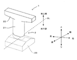
図1は橋梁構造の一例を模式的に示す図である。この橋梁構造は都市高速道路や鉄道の高架橋1に適用されるものである。この高架橋1は、上部構造(図示省略)と、上部構造から作用する鉛直荷重及び水平荷重を支持するコンクリート橋脚2とを有している。この実施形態では、コンクリート橋脚2は、いわゆるT型橋脚であり、図1に示すように、1本の柱部21と、柱部21の頂部に横設された梁部22と、柱部21の下端に連なるコンクリート製のフーチング23と、フーチング23を支持する複数の基礎杭(図示省略)とを有している。なお、基礎杭とフーチング23と柱部21の下端部とは地表面GLの下方に埋設されている。また、同図および後で説明する各図では、橋梁の各部の位置関係を明確にするために、コンクリート橋脚2の梁部22の横設方向を「左右方向」とし、それに直交する水平方向を「前後方向」とし、鉛直方向を「上下方向」としている。
FIG. 1 is a diagram schematically showing an example of a bridge structure. This bridge structure is applied to an urban expressway or a
このように構成されたコンクリート橋脚2では、コンクリート橋脚2の強度や耐震性を高めるためには、長円断面(あるいは陸上競技場形状を有する断面)を有する柱部21および矩形断面を有する梁部22とを補強することが重要となる。そこで、本実施形態では、後で説明するコンクリート橋脚用補強器具(=補強金具+緊締部材)を用いてコンクリート橋脚2の各部を補強している。以下、図2、図3A、図3B、図3Cおよび図4を参照しつつコンクリート橋脚2の補強工程について説明する。
In the concrete pier 2 configured as described above, in order to increase the strength and earthquake resistance of the concrete pier 2, the
図2は本発明にかかるコンクリート橋脚用補強器具を用いてコンクリート橋脚を補強する補強工法を示すフローチャートである。コンクリート橋脚を補強するために、まず最初に、地表面GLを掘削してコンクリート橋脚2のうちフーチング23と接続される柱部21の下端部、つまりフーチング接続部位を露出させる(ステップS1)。そして、コンクリート橋脚2の柱部21および梁部22に対し、補強器具3、4をそれぞれ仮装着する(ステップS2)。補強器具3,4は、それぞれコンクリート橋脚2の柱部21をおよび梁部22を補強するための器具である。ここで、柱部21は長円断面を有するのに対し、梁部22は矩形断面を有しているため、補強器具3は柱部補強用の係合部材31を用いるのに対し、補強器具4は梁部補強用の係合部材41を用いている。そこで、図3A、図3Bおよび図3Cを参照しつつ柱部補強用の補強器具3の構成について説明した後で、図4A、図4Bおよび図4Cを参照しつつ梁部補強用の補強器具4の構成について説明する。
FIG. 2 is a flowchart showing a reinforcing method for reinforcing a concrete pier using the concrete pier reinforcement device according to the present invention. In order to reinforce the concrete pier, first, the ground surface GL is excavated to expose the lower end portion of the
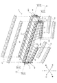
図3Aはコンクリート橋脚の柱部を補強する補強器具および補強器具の施工を模式的に示す図である。また、図3Bは柱部補強用の係合部材を示す図である。さらに、図3Cは柱部補強用の支持金具を示す図である。補強器具3は、図3Aに示すように、略T字断面を有する4本の係合部材31と、2種類の緊締部材32、33と、複数の支持部材34とを有している。係合部材31は図3Bに示すように上下方向に延設され、その水平断面は略T字形状を有している。つまり、係合部材31では、上下方向に延設された鋼片311の一方面が柱部21の側面に係合可能に仕上げられるとともに、鋼片311の他方面の中央縦領域から前方向(あるいは後方向)に鋼片312が突設されている。このように構成された係合部材31は長円の直線部分の4カ所で鋼片311を柱部21の側面に係合している。各係合部材31には、緊締部材32の一構成要素であるPC鋼棒を挿入するための貫通孔313が複数個、鋼片312に対して上下方向に一列で穿設されている。そして、柱部21の各側面で互いに離間して配置されている2つの係合部材31の間では、緊締部材32が取り付けられる。
FIG. 3A is a diagram schematically showing a reinforcing device for reinforcing a pillar portion of a concrete pier and the construction of the reinforcing device. Moreover, FIG. 3B is a figure which shows the engaging member for pillar part reinforcement. Further, FIG. 3C is a view showing a support metal fitting for reinforcing a column portion. As shown in FIG. 3A, the reinforcing
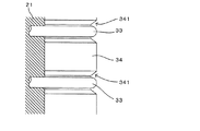
各緊締部材32は上記係合部材31の間に渡されるストレートなPC鋼棒と、各PC鋼棒の両端に螺合するナットとで構成されている。一方、柱部21を挟んで前後方向に配置される係合部材31の間では、もう一方の緊締部材33が取り付けられる。各緊締部材33は上記係合部材31の間に渡される湾曲形状のPC鋼棒と、各PC鋼棒の両端に螺合するナットとで構成されている。なお、PC鋼棒が柱部21に接触するのを防止するために、複数の支持部材34がPC鋼棒と柱部21の湾曲側面との間に配置されている。各支持部材34は柱部21の表面に対して係合自在に設けられた柱形状を有しており、その外面は柱部21の湾曲形状に対応して湾曲状に形成されている。また、各支持部材34の外面には、図3Cに示すように、緊締部材33のPC鋼棒を案内するガイド溝341が形成されている。このため、支持部材34を設けた分だけ柱部21から緊締部材33を離間して配置し、後で詳述するように、その間に主筋を配設可能となっている。
Each tightening
係合部材31を緊締部材32、33により相互接続することで、上記したようにコンクリート橋脚2の柱部21に補強器具3が仮装着される(後で説明する図5参照)。また、後で説明するように、仮装着後に各ナットを締め付けることで係合部材31の間に緊張力を与え、柱部21を取り囲みながら圧縮応力を与えることが可能となっている。
By connecting the engaging
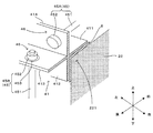
図4Aはコンクリート橋脚の梁部を補強する補強器具および補強器具の施工を模式的に示す図であり、図4Bは梁部補強用の補強器具の部分拡大図であり、図4Cは梁部補強用の補強器具の部分断面図である。梁部補強用の補強器具4は柱部21の上部から左右方向に翼状に延びる梁部22を補強対象として補強するための器具であり、梁部22の上方隅角部221と係合する2本の係合部材41と、梁部22の右下隅角部422と係合する2本の係合部材42と、梁部22の左下隅角部423と係合する2本の係合部材43と、梁部22の側方隅角部424と係合する4本の係合部材44と、係合部材41〜44の間で接続されて緊張力を与える緊締部材45とを有している。なお、本実施形態では、上下方向において梁部22は柱部21と接続された位置で最も厚く、右方向および左方向に進むにしたがって薄くなるように構成されており、梁部22の右下隅角部422および左下隅角部423は水平方向に対して傾斜している。このため、係合部材41と、係合部材42、43とは非平行状態となっている。この点を考慮し、本実施形態では、緊締部材45として、平行状態の係合部材を接続する平行用の緊締部材45Aと、非平行状態の係合部材を接続する非平行用の緊締部材45Bとの2種類を用いている。
FIG. 4A is a diagram schematically showing a reinforcing device for reinforcing a beam portion of a concrete pier and construction of the reinforcing device, FIG. 4B is a partially enlarged view of a reinforcing device for reinforcing a beam portion, and FIG. FIG. The
各係合部材41は、図4Bに示すように、梁部22の上方隅角部221の延設方向(橋梁の左右方向)に延設された第1鋼片411、第2鋼片412、第3鋼片413および第4鋼片414を断面十字状に結合した構造を有している。具体的には、2本の山形鋼を溶接して形成することができる。もちろん、十字形の断面を有する形鋼をそのまま係合部材41として用いてもよいし、4つの鋼片を溶接して形成してもよい。このような構成を有する係合部材41では、第1鋼片411および第2鋼片412が互いに直交して結合されて上方隅角部221に係合可能となっている。また、第1鋼片411と直交して結合された第4鋼片414には第1緊締部材45を係止する第1係止部46が設けられ、第1緊締部材45の緊張力によって第2鋼片412を補強対象に押し付けることが可能となっている。さらに、第2鋼片412と直交して結合された第3鋼片413には第2緊締部材45を係止する第2係止部46が設けられ、第2緊締部材45の緊張力によって第1鋼片411を補強対象に押し付けることが可能となっている。なお、その他の係合部材42〜44は、長さや係合位置などについては係合部材41と相違するものの、基本構造について共通する。そこで、以下においては係合部材42〜44の各部に相当符号を付し、詳しい構成説明については省略する。
As shown in FIG. 4B, each engaging
このように構成された係合部材41〜44はそれぞれ梁部22の隅角部221〜224に係合するように配置され、複数の緊締部材45(45A、45B)によって相互に接続される。より詳しくは、係合部材41同士、係合部材42同士、係合部材43同士および係合部材44同士は互いに平行配置されているため、複数の緊締部材45Aにより相互接続される。各緊締部材45Aは、緊締部材32と同様に、上記係合部材の間に渡されるストレートなPC鋼棒451と、各PC鋼棒451の両端に螺合するナット452とで構成されている。一方、係合部材41と、係合部材42、43とは非平行となっているため、複数の緊締部材45Bにより相互接続される。各緊締部材45Bが緊締部材45Aと大きく相違する点は、図4Cに示すように、半球体状の摺動体453を有する点である。この摺動体453は係合部材41を構成する第3鋼片413の第2係止部46に予め設けられたお椀状の凹部461に摺接自在となっており、摺動体453を介してPC鋼棒451の端部が第3鋼片413に係止される。このため、PC鋼棒451は第3鋼片413に対して揺動自在に軸支される。この点については、係合部材42、43側でも同様である。したがって、係合部材41、42を相互に接続する緊締部材45Bや係合部材41、43を相互に接続する緊締部材45Bでは、図4Aおよび4Cに示すように、緊締部材45Bの取付位置に応じてPC鋼棒451の傾き角θは変動するが、その変動量に応じて緊締部材45Bを揺動させて取り付けることができる。したがって、互いに非平行に配置された係合部材を緊締部材45Bによって良好に接続することができる。なお、例えば係合部材41同士が非平行となっている場合には、係合部材41を構成する第4鋼片414の第1係止部46にお椀状の凹部461を予め設け、緊締部材45Bを接続すればよい。この点については他の係合部材についても同様である。
The engaging
図5の(a)欄に示すように係合部材41〜44を緊締部材45(45A、45B)により相互接続することで、上記したようにコンクリート橋脚2の梁部22に補強器具4が仮装着される。また、後で説明するように、仮装着後に各ナットを締め付けることで係合部材41〜44の間に緊張力を与え、梁部22を取り囲みながら圧縮応力を与えることが可能となっている。なお、図5中の中央段はコンクリート橋脚2の側面を模式的に図示し、上段はコンクリート橋脚2の平面を模式的に図示し、下段はコンクリート橋脚2の柱部21の断面を模式的に図示している。
As shown in the column (a) of FIG. 5, the engaging
図2に戻って補強工法の説明を続ける。上記仮装着が完了する(ステップS2)と、図5中の(b)欄に示すように、緊締部材45に対して主筋5を仮結束する(ステップS3)。それに続けて緊締部材45のナットを締め付けてPC鋼棒を緊張させる(ステップS4)。これによって、柱部21に対しては柱部21の軸線方向(上下方向)と直交する方向から圧縮応力が与えられ、梁部22を取り囲むように圧縮応力が与えられる。その結果、コンクリート橋脚2が良好に補強される。
Returning to FIG. 2, the description of the reinforcing method will be continued. When the temporary attachment is completed (step S2), as shown in the column (b) in FIG. 5, the
また、緊締部材45の緊張後に、これら緊張状態にある緊締部材45に対して主筋5を最終的に強固に結束する(ステップS5)。そして、主筋5の最終結束後に、図5中の(c)欄に示すように、コンクリート橋脚2を取り囲むように型枠6を設置し(ステップS6)、補強器具3、4が装着されたコンクリート橋脚2と型枠6との間にコンクリートを打設し(ステップS7)、さらにコンクリート養生を行う(ステップS8)。こうしてコンクリート橋脚2の補強を完了する。なお、本実施形態では、型枠6として、外面に化粧が施されて残存型枠を用いるため、上記補強器具3、4およびコンクリートで補強されたコンクリート橋脚2から型枠6を取り外す必要がなく、補強コストの低減とともに優れた美観を確保することができる。
Further, after the tightening
以上のように、本実施形態では、補強対象となる梁部22の隅角部に対して係合部材41〜44を構成する第1鋼片および第2鋼片を係合させながら緊締部材45の緊張力により押し付けてコンクリート橋脚2の補強を行っている。したがって、コンクリート橋脚2に対して加工を加えることなく、補強器具4によって圧縮応力を加えてコンクリート橋脚2の強度および耐震性を向上させることができる。
As described above, in the present embodiment, the tightening
また、上記実施形態では、係合部材41〜43の第3鋼片に対して揺動自在に軸支された緊締部材45Bを用いて非平行状態の係合部材41、42ならびに非平行状態の係合部材41、43を接続して緊張力を与えるように構成している。このため、図1や図2に示すように、梁部22の横設方向(左右方向)において矩形断面の大きさが変化する場合においても、梁部22に係合部材をしっかりと装着して補強器具4による梁部22の補強性能を高めている。
Moreover, in the said embodiment, the
また、柱部21についても柱部21の断面形状に沿って補強器具3を装着することができ、上記補強器具4とともにコンクリート橋脚2を補強している。したがって、コンクリート橋脚2は優れた強度および耐震性を有している。
In addition, the reinforcing
このように本実施形態では、係合部材41〜44が本発明の「コンクリート橋脚用補強金具」の一例に相当し、当該係合部材41〜44と緊締部材45とを有する補強器具4が本発明の「コンクリート橋脚用補強器具」の一例に相当している。また、梁部22の横設方向(図面中の左右方向)が本発明の「延設方向」に相当している。また、ステップS2、S3がそれぞれ本発明の「第1工程」および「第2工程」の一例に相当し、ステップS4、S5が本発明の「第3工程」の一例に相当し、ステップS6、S7が本発明の「第4工程」の一例に相当している。
Thus, in this embodiment, the engaging
なお、本発明は上記した実施形態に限定されるものではなく、その趣旨を逸脱しない限りにおいて上述したもの以外に種々の変更を行うことが可能である。例えば上記実施形態では、例えば図4Bに示すように係合部材41の端部に対して特段の加工を施していないが、例えば図6に示すように各端部において鋼片同士を連結片7によって連結してもよく、これによって鋼片の変形を効果的に防止することができる。なお、係合部材41〜44の端部への連結片7の連結は溶接などを用いることができる。また、係合部材42の製造時に連結片7が形成してもよい。また、連結片7の追加位置については、係合部材41〜44の端部に限定されるものではなく、PC鋼棒451を挿通させるための貫通孔を避けながら略三角形状の補強リブを連結片7として溶接などによって取り付けてもよく、これによって鋼片の変形をさらに効果的に防止することができる。また、図7に示すように、連結片7の追加については、係合部材31に適用してもよい。
The present invention is not limited to the above-described embodiment, and various modifications other than those described above can be made without departing from the spirit of the present invention. For example, in the above-described embodiment, for example, as shown in FIG. 4B, the end of the engaging
また、係合部材41については、複数の係合部材を連結して構成してもよい。例えば図8に示すように、複数の係合部材41a、41bの端部に連結片7を取り付けるとともに各連結片7に貫通孔71を設け、両者の端部を突き合わせた状態で貫通孔71に対してボルト72を挿通させ、ナット73で締結することで係合部材を相互に連結してもよい。もちろん、このような連結組み合わせは係合部材41に限定されるものではなく、他の係合部材42〜44についても同様である。
Further, the engaging
また、上記実施形態では、図9(a)に示すように、鋼片411〜414の幅Wはいずれも一定であるが、図9(b)に示すように鋼片411〜414の幅Wを相互に異ならせてもよい。 Moreover, in the said embodiment, as shown to Fig.9 (a), although all the width W of the steel pieces 411-414 is constant, as shown in FIG.9 (b), the width W of the steel pieces 411-414. May be different from each other.
また、例えば図10に示すように隅角部221と係合部材41との間にゴムや樹脂などの変形可能なシート8を介挿させてもよく、シート8を介して両者が密着して緊締部材45の緊張による圧縮応力を梁部22に与えることができる。また、係合部材42〜44と梁部22との間にゴムや樹脂などの変形可能なシート8を介挿させてもよく、上記と同様の作用効果が得られる。
Further, for example, as shown in FIG. 10, a
また、上記実施形態では、緊締部材45の一構成要素としてPC鋼棒451を用いているが、例えばPC鋼棒の代わりにネジ鉄筋棒や鋼線などを用いてもよい。
Moreover, in the said embodiment, although the
さらに、上記実施形態では、長円断面の柱部21を有するT型のコンクリート橋脚2に対して本発明を適用しているが、本発明の適用対象はこれに限定されるものではなく、矩形断面の柱部21を有するコンクリート橋脚2にも適用可能であり、この場合、梁部22と同様にして柱部21を補強することができる。また、T型以外のコンクリート橋脚、例えば逆L型、V型、Y型、ラーメン型などのコンクリート橋脚のうち矩形断面を有する柱部や梁部などの補強対象として本発明により補強することができる。
Furthermore, in the said embodiment, although this invention is applied with respect to the T-shaped concrete pier 2 which has the
この発明は、矩形断面を有する柱部または梁部などの補強対象を含むコンクリート橋脚を補強する技術全般に適用することができる。 The present invention can be applied to all techniques for reinforcing concrete piers including objects to be reinforced such as columns or beams having a rectangular cross section.
2…コンクリート橋脚
4…補強器具
5…主筋
22…梁部(補強対象)
41,41a,41b,42〜44…係合部材(補強金具)
45,45A,45B…緊締部材
46…第1係止部,第2係止部
221〜224…隅角部
411…第1鋼片
412…第2鋼片
413…第3鋼片
414…第4鋼片
2…
41, 41a, 41b, 42 to 44 ... engaging members (reinforcing metal fittings)
45, 45A, 45B ... tightening
Claims (4)
前記隅角部の延設方向に設けられた第1鋼片、第2鋼片、第3鋼片および第4鋼片が断面十字状に結合され、
前記第1鋼片および前記第2鋼片が互いに直交して結合されて前記隅角部に係合可能となっており、
前記第1鋼片と直交して結合された前記第4鋼片には第1緊締部材を係止する第1係止部が設けられ、前記第1緊締部材の緊張力によって前記第2鋼片を前記補強対象に押し付け、
前記第2鋼片と直交して結合された前記第3鋼片には第2緊締部材を係止する第2係止部が設けられ、前記第2緊締部材の緊張力によって前記第1鋼片を前記補強対象に押し付ける
ことを特徴とするコンクリート橋脚用補強金具。 A concrete pier that reinforces the concrete pier by applying a tension force of a tightening member to the reinforcement object while engaging a corner portion of the reinforcement object with a column portion or a beam portion having a rectangular cross section among the concrete piers. Reinforcing metal fittings,
The first steel piece, the second steel piece, the third steel piece and the fourth steel piece provided in the extending direction of the corner portion are combined in a cross-shaped cross section,
The first steel piece and the second steel piece are coupled orthogonally to each other and engageable with the corner portion,
The fourth steel piece, which is coupled perpendicularly to the first steel piece, is provided with a first locking portion for locking the first fastening member, and the second steel piece is formed by the tension of the first fastening member. Against the object to be reinforced,
The third steel piece joined orthogonally to the second steel piece is provided with a second locking portion for locking the second fastening member, and the first steel piece is squeezed by the tension of the second fastening member. A reinforcing metal fitting for a concrete pier, which is pressed against the object to be reinforced.
前記第1係止部および前記第2係止部のうちの少なくとも一方は前記緊締部材を揺動自在に軸支するコンクリート橋脚用補強金具。 Reinforcing metal fittings for concrete piers according to claim 1,
At least one of the first locking part and the second locking part is a concrete bridge pier reinforcing bracket for pivotally supporting the tightening member.
前記補強対象の矩形断面を構成する4つの隅角部の各々に設けられる、請求項1または2に記載のコンクリート橋脚用補強金具と、
前記補強対象の矩形断面において互いに隣接する前記コンクリート橋脚用補強金具を接続して緊張させる複数の緊締部材と
を備えることを特徴とするコンクリート橋脚用補強器具。 The concrete bridge pier is a reinforcing member for a concrete pier that reinforces the reinforcement object, with a column or beam having a rectangular cross section as a reinforcement object,
The reinforcing metal fittings for concrete piers according to claim 1 or 2, provided at each of the four corners constituting the rectangular cross section of the object to be reinforced,
A concrete pier reinforcement device comprising: a plurality of tightening members that connect and tighten the concrete pier reinforcements adjacent to each other in the rectangular cross section to be reinforced.
前記補強対象の矩形断面を構成する4つの隅角部の各々に対し、請求項1または2に記載のコンクリート橋脚用補強金具を係合させるとともに、互いに隣接する前記コンクリート橋脚用補強金具の間に緊締部材を接続することで、前記補強対象に対して前記コンクリート橋脚用補強金具を仮装着する第1工程と、
前記緊締部材と、前記補強対象との間に主筋を配設するとともに、前記緊締部材に対して前記主筋を仮結束する第2工程と、
前記緊締部材を緊張させた後で、前記主筋を前記緊締部材に結束する第3工程と、
前記コンクリート橋脚用補強金具、前記緊締部材および前記主筋を取り囲むように型枠を設置した後で、コンクリートを打設する第4工程と、を備え、
前記第1工程ないし前記第4工程をこの順序で実行することを特徴とするコンクリート橋脚の補強工法。 The concrete bridge pier is a reinforcement method for a concrete pier that reinforces the reinforcement object with a pillar or beam having a rectangular cross section among the concrete piers,
The concrete pier reinforcement metal fitting according to claim 1 or 2 is engaged with each of the four corner portions constituting the rectangular cross section to be reinforced, and between the concrete pier reinforcement metal fittings adjacent to each other. A first step of temporarily attaching the reinforcing metal fitting for concrete pier to the object to be reinforced by connecting a tightening member;
A second step of disposing a main bar between the tightening member and the object to be reinforced, and temporarily binding the main bar to the tightening member;
A third step of binding the main bar to the tightening member after tensioning the tightening member;
A fourth step of placing concrete after installing the formwork so as to surround the reinforcing metal fitting for concrete pier, the tightening member and the main reinforcement,
The concrete pier reinforcement method, wherein the first to fourth steps are executed in this order.
Priority Applications (1)
| Application Number | Priority Date | Filing Date | Title |
|---|---|---|---|
| JP2016237392A JP6176385B1 (en) | 2016-12-07 | 2016-12-07 | Reinforcement fittings for concrete piers, reinforcement equipment for concrete piers, and reinforcement methods for concrete piers |
Applications Claiming Priority (1)
| Application Number | Priority Date | Filing Date | Title |
|---|---|---|---|
| JP2016237392A JP6176385B1 (en) | 2016-12-07 | 2016-12-07 | Reinforcement fittings for concrete piers, reinforcement equipment for concrete piers, and reinforcement methods for concrete piers |
Publications (2)
| Publication Number | Publication Date |
|---|---|
| JP6176385B1 JP6176385B1 (en) | 2017-08-09 |
| JP2018091099A true JP2018091099A (en) | 2018-06-14 |
Family
ID=59559093
Family Applications (1)
| Application Number | Title | Priority Date | Filing Date |
|---|---|---|---|
| JP2016237392A Active JP6176385B1 (en) | 2016-12-07 | 2016-12-07 | Reinforcement fittings for concrete piers, reinforcement equipment for concrete piers, and reinforcement methods for concrete piers |
Country Status (1)
| Country | Link |
|---|---|
| JP (1) | JP6176385B1 (en) |
Cited By (1)
| Publication number | Priority date | Publication date | Assignee | Title |
|---|---|---|---|---|
| KR101991938B1 (en) * | 2018-07-16 | 2019-06-21 | (주)아리터 | Device for reinforcing the Earthquake of a concrete columns and Methods |
Citations (9)
| Publication number | Priority date | Publication date | Assignee | Title |
|---|---|---|---|---|
| US5444952A (en) * | 1994-12-12 | 1995-08-29 | Jackson; Paul R. | Chimney reinforcing device |
| JPH09151613A (en) * | 1995-09-27 | 1997-06-10 | Hazama Gumi Ltd | Reinforcement structure for existing concrete columnar body |
| JPH11222821A (en) * | 1998-02-04 | 1999-08-17 | East Japan Railway Co | Reinforcing method of reinforced concrete column |
| JP2000120023A (en) * | 1998-10-13 | 2000-04-25 | East Japan Railway Co | Earthquake-resisting reinforcing method for reinforced concrete pole |
| JP2000192672A (en) * | 1998-12-25 | 2000-07-11 | High Frequency Heattreat Co Ltd | Reinforcing tool and reinforcing method for concrete rodlike structure |
| JP2000352111A (en) * | 1999-06-14 | 2000-12-19 | East Japan Railway Co | Concrete member reinforcing bar anchor member |
| JP2005232750A (en) * | 2004-02-18 | 2005-09-02 | High Frequency Heattreat Co Ltd | Reinforcing fitting for concrete structure |
| JP2006132261A (en) * | 2004-11-09 | 2006-05-25 | East Japan Railway Co | Method of reinforcing reinforced concrete rod member, and device for reinforcing the same |
| CN102080454A (en) * | 2010-12-02 | 2011-06-01 | 西安建筑科技大学 | Method for reinforcing pillars in buildings |
-
2016
- 2016-12-07 JP JP2016237392A patent/JP6176385B1/en active Active
Patent Citations (9)
| Publication number | Priority date | Publication date | Assignee | Title |
|---|---|---|---|---|
| US5444952A (en) * | 1994-12-12 | 1995-08-29 | Jackson; Paul R. | Chimney reinforcing device |
| JPH09151613A (en) * | 1995-09-27 | 1997-06-10 | Hazama Gumi Ltd | Reinforcement structure for existing concrete columnar body |
| JPH11222821A (en) * | 1998-02-04 | 1999-08-17 | East Japan Railway Co | Reinforcing method of reinforced concrete column |
| JP2000120023A (en) * | 1998-10-13 | 2000-04-25 | East Japan Railway Co | Earthquake-resisting reinforcing method for reinforced concrete pole |
| JP2000192672A (en) * | 1998-12-25 | 2000-07-11 | High Frequency Heattreat Co Ltd | Reinforcing tool and reinforcing method for concrete rodlike structure |
| JP2000352111A (en) * | 1999-06-14 | 2000-12-19 | East Japan Railway Co | Concrete member reinforcing bar anchor member |
| JP2005232750A (en) * | 2004-02-18 | 2005-09-02 | High Frequency Heattreat Co Ltd | Reinforcing fitting for concrete structure |
| JP2006132261A (en) * | 2004-11-09 | 2006-05-25 | East Japan Railway Co | Method of reinforcing reinforced concrete rod member, and device for reinforcing the same |
| CN102080454A (en) * | 2010-12-02 | 2011-06-01 | 西安建筑科技大学 | Method for reinforcing pillars in buildings |
Cited By (1)
| Publication number | Priority date | Publication date | Assignee | Title |
|---|---|---|---|---|
| KR101991938B1 (en) * | 2018-07-16 | 2019-06-21 | (주)아리터 | Device for reinforcing the Earthquake of a concrete columns and Methods |
Also Published As
| Publication number | Publication date |
|---|---|
| JP6176385B1 (en) | 2017-08-09 |
Similar Documents
| Publication | Publication Date | Title |
|---|---|---|
| JP5946041B2 (en) | Column beam connection structure, column beam connection method, and precast concrete stigma member | |
| KR20160026213A (en) | Pedestrian bridge design and construction method using ready made h-beam with prestressed forces on column inside connection | |
| JP6176385B1 (en) | Reinforcement fittings for concrete piers, reinforcement equipment for concrete piers, and reinforcement methods for concrete piers | |
| JP5336125B2 (en) | Mounting structure for reinforcing members in structures | |
| JP6255220B2 (en) | Positioning member and construction method | |
| JP6432786B2 (en) | Beam material load bearing structure and beam material repair method | |
| JP6142228B1 (en) | Reinforcing equipment for concrete pier and concrete pier reinforcement method | |
| JP6147628B2 (en) | Joint structure of concrete column and steel beam | |
| JP2017150289A (en) | Reinforcement/repair structure and method for steel structure | |
| JP6802675B2 (en) | Beam-column joining method and joint member | |
| JP6918469B2 (en) | Construction method of precast member, erection structure of precast member, erection structure of precast member | |
| JP6717782B2 (en) | Reinforcement method for existing footing | |
| JP6734156B2 (en) | Anchor fixing structure and anchor fixing method | |
| JP4865104B2 (en) | Design method for composite structural beams | |
| JP6148697B2 (en) | Formwork | |
| JP6205199B2 (en) | Reinforcement structure of columnar structure | |
| JP6829631B2 (en) | Construction method of column base, reinforcement method of existing column base | |
| JP6646959B2 (en) | Column and beam frame and its construction method | |
| JP2009281011A (en) | Joint structure of concrete building, and its construction method | |
| JP3856745B2 (en) | Bending reinforcement method for joints between existing columns and beams or slabs | |
| CN210529934U (en) | I-steel fixed knot that encorbelments constructs and braced system | |
| KR102598628B1 (en) | A non-welding rebar anchoring device that can adjust the arrangement structure in response to the rebar arrangement structure and a method using the same | |
| JP7270412B2 (en) | Reinforcement structure of masonry building | |
| JP6917051B2 (en) | Reinforcement structure of existing structure | |
| JP6989908B2 (en) | Reinforcing material connection structure and connection method |
Legal Events
| Date | Code | Title | Description |
|---|---|---|---|
| A975 | Report on accelerated examination |
Free format text: JAPANESE INTERMEDIATE CODE: A971005 Effective date: 20170609 |
|
| TRDD | Decision of grant or rejection written | ||
| A01 | Written decision to grant a patent or to grant a registration (utility model) |
Free format text: JAPANESE INTERMEDIATE CODE: A01 Effective date: 20170620 |
|
| A61 | First payment of annual fees (during grant procedure) |
Free format text: JAPANESE INTERMEDIATE CODE: A61 Effective date: 20170626 |
|
| R150 | Certificate of patent or registration of utility model |
Ref document number: 6176385 Country of ref document: JP Free format text: JAPANESE INTERMEDIATE CODE: R150 |