JP2018089286A - Roll finishing machine - Google Patents
Roll finishing machine Download PDFInfo
- Publication number
- JP2018089286A JP2018089286A JP2016237420A JP2016237420A JP2018089286A JP 2018089286 A JP2018089286 A JP 2018089286A JP 2016237420 A JP2016237420 A JP 2016237420A JP 2016237420 A JP2016237420 A JP 2016237420A JP 2018089286 A JP2018089286 A JP 2018089286A
- Authority
- JP
- Japan
- Prior art keywords
- roll
- linen
- roller
- pressing
- transport
- Prior art date
- Legal status (The legal status is an assumption and is not a legal conclusion. Google has not performed a legal analysis and makes no representation as to the accuracy of the status listed.)
- Granted
Links
Images

Landscapes
- Treatment Of Fiber Materials (AREA)
Abstract
Description
本発明は、ホテル、病院等で使用されたシーツ、包布、タオル等のリネン品を洗濯し乾燥した後に、連続してアイロンを掛けて仕上げるロール仕上げ機に関する。 The present invention relates to a roll finishing machine for washing and drying linen items such as sheets, wrapping cloths, towels and the like used in hotels, hospitals, etc., and then continuously ironing them.
ホテル、病院等で使用されたシーツ、包布、タオルといった使用済みの大量のリネン品(洗濯物)は、リネンサプライ工場に回収される。リネンサプライ工場では、回収した使用済みのリネン品を洗濯し乾燥した後に、ロール仕上げ機(ロールアイロナー)によってアイロンを掛けて仕上げられる。リネンサプライ工場にて、洗濯し乾燥した後にアイロンを掛けて仕上げられたリネン品は、ホテル、病院等へ配送される。 A large amount of used linen items (laundries) such as sheets, wrappings, and towels used in hotels, hospitals, etc. are collected at a linen supply factory. In the linen supply factory, the collected used linen products are washed and dried, and then ironed by a roll finishing machine (roll ironer). Linen products that have been ironed after being washed and dried at the linen supply factory are delivered to hotels, hospitals and the like.
リネンサプライ工場では、タオル等は乾燥機によって完全に乾燥される。シーツや包布、枕カバー等のいわゆる平物は、しわを伸ばしてアイロンが掛けられる(アイロニング)。このため、シーツや包布、枕カバー等のいわゆる平物は、少し湿った状態で乾燥機から取り出される。乾燥機から少し湿った状態で取り出されたシーツや包布、枕カバーは、ロール仕上げ機によって「しわ伸ばし」と「仕上げ乾燥」が行われる。 In the linen supply factory, towels are completely dried by a dryer. So-called flat objects such as sheets, wrapping, and pillowcases are wrinkled and ironed (ironing). For this reason, so-called flat objects such as sheets, wrapping sheets, pillow covers, etc. are taken out of the dryer in a slightly moist state. Sheets, wrappings, and pillowcases taken out of the dryer in a slightly wet state are “wrinkled” and “finish dried” by a roll finisher.
アイロニングを行うロール仕上げ機には、チェスト式とカレンダ式とがある。チェスト式のロール仕上げ機としては、特許文献1、2で提案されている。チェスト式のロール仕上げ機は、加熱された加熱ベッドと、この加熱ベッドにリネン品を押圧しながら回転するロールとを有している。そして、加熱ベッドとロールとの間に搬送された少し湿った状態のシーツや包布、枕カバー等は、ロールによって加熱ベッドへ押圧されながら、ロールの回転により搬送される。これにより、シーツや包布、枕カバー等には、大きな圧迫力(押圧力)が加わるので「しわ伸ばし」され、加熱ベッドにより「仕上げ乾燥」が行われて仕上げられる。
There are chest type and calendar type roll finishing machines that perform ironing.
このようなチェスト式のロール仕上げ機では、加熱ベッドとロールからなる複数台の仕上げ機を順番に並べて用いている。リネン品は前段の加熱ベッドとロールとの間から次段の加熱ベッドとロールとの間に順次搬送される。前段のロールの回転数よりも、次段のロールの回転数は速く設定されている。これにより、複数台の加熱ベッドとロールの間を順番に搬送されるリネン品にはテンション(張力)が付与されるので、搬送中でのしわの発生が防止されている。このように、搬送中にリネン品にしわが発生しないようにテンション(張力)を付与する必要があるので、一般的にロール仕上げ機は、加熱ベッドとロールからなる複数台の仕上げ機を必要としていた。 In such a chest type roll finishing machine, a plurality of finishing machines each consisting of a heating bed and a roll are used in order. Linen products are sequentially transported between the heating bed and roll of the previous stage and between the heating bed and roll of the next stage. The rotation speed of the next-stage roll is set faster than the rotation speed of the previous-stage roll. Thereby, since tension (tension) is given to the linen article conveyed in order between a plurality of heating beds and rolls, generation of wrinkles during conveyance is prevented. As described above, since it is necessary to apply tension (tension) so that wrinkles are not generated in the linen product during transportation, a roll finishing machine generally requires a plurality of finishing machines including a heating bed and a roll. .
ところが、複数台の仕上げ機を用いる場合、複数本のロールを回転駆動するための大きな動力を必要とし、ロール仕上げ機自体も大型化する。 However, when a plurality of finishing machines are used, a large power is required for rotationally driving a plurality of rolls, and the roll finishing machine itself is also increased in size.
また、洗濯物を加熱ベッドとロールとの間に搬送する場合、リネン品の後端側にはしわが発生し易く、しわの寄ったまま加熱ベッドとロールとの間に搬送されてしまうおそれがある。 In addition, when the laundry is transported between the heating bed and the roll, wrinkles are likely to occur on the rear end side of the linen product, and there is a risk that the wrinkle may be transported between the heating bed and the roll. is there.
そこで、本発明は、大きな動力を必要とせず、しわの発生を防止することができるロール仕上げ機の提供を目的とする。 Accordingly, an object of the present invention is to provide a roll finishing machine that does not require a large amount of power and can prevent the generation of wrinkles.
上記課題を解決するための本発明の一態様は、長尺状で長手方向に対して交差する断面の形状が弧状に形成された凹部の表面上に、洗濯し乾燥した後のリネン品が搬送されこのリネン品を加熱する加熱ベッドと、前記加熱ベッドの前記凹部内に一方向に回転する状態で配置されて前記凹部の表面側との間に前記リネン品が搬送される搬送路を形成し、この搬送路内に搬送された前記リネン品を前記凹部の表面側へ押圧しながら回転することで前記リネン品をプレスする主ロールと、前記搬送路の入り口に配置された搬送支持台とこの搬送支持台に巻き掛けられて前記リネン品を前記搬送路の入り口まで搬送する搬送ベルトとを備えた搬送機構と、を有するロール仕上げ機において、前記搬送路の入り口近傍であって前記主ロールに近接して配置され、前記搬送路の入り口に搬送された前記リネン品を前記搬送支持台側へ押圧する押圧ローラを設けたことを特徴とする。 One aspect of the present invention for solving the above problems is that a linen product after being washed and dried is conveyed on the surface of a recess having an elongated shape and a cross-sectional shape intersecting the longitudinal direction formed in an arc shape. And a heating path that heats the linen product, and a conveyance path that is arranged in a state of rotating in one direction in the concave portion of the heating bed and that conveys the linen product between the surface side of the concave portion. A main roll that presses the linen product by rotating the linen product conveyed into the conveyance path while pressing the linen product against the surface side of the recess, a conveyance support base disposed at the entrance of the conveyance path, and A roll finishing machine having a conveyance belt that is wound around a conveyance support and conveys the linen product to the entrance of the conveyance path, and is near the entrance of the conveyance path to the main roll. Closely arranged Is characterized in that the conveying path the linen products transported to the entrance is provided a pressing roller that presses into the transport support base side.
また、本発明の一態様としては、前記押圧ローラは、前記主ロールと平行に配置されたローラと、このローラを前記搬送支持台側へ押圧する駆動部と、この駆動部と前記ローラの軸方向端部とを連結し前記駆動部の駆動力で揺動し前記ローラを前記搬送支持台側へ移動させる押圧レバーと、を有することが好ましい。 Further, according to one aspect of the present invention, the pressing roller includes a roller disposed in parallel with the main roll, a driving unit that presses the roller toward the conveyance support base, and a shaft of the driving unit and the roller. It is preferable to include a pressing lever that is connected to the direction end portion and swings by the driving force of the driving unit to move the roller to the transport support base side.
また、本発明の一態様としては、前記ローラは、少なくとも外周表面が弾性を有する材質で形成された押圧外周を有することが好ましい。 As an aspect of the present invention, it is preferable that the roller has a pressing outer periphery formed of a material having at least an outer peripheral surface having elasticity.
また、本発明の一態様としては、前記加熱ベッドは、長尺状で長手方向に対して交差する断面形状が弧状に形成された加熱板と、この加熱板の長手方向の両側部をそれぞれ支持する側板部と、前記加熱ベッドの裏面側に設けられて加熱板を加熱する加熱部とを備えていることが好ましい。 Moreover, as one aspect of the present invention, the heating bed supports a heating plate having an elongated shape and an arc-shaped cross section intersecting the longitudinal direction, and both sides of the heating plate in the longitudinal direction. It is preferable to include a side plate portion that performs heating and a heating portion that is provided on the back side of the heating bed and heats the heating plate.
本発明によれば、リネン品の搬送路の入り口近傍であって主ロールに近接して、リネン品を搬送支持台側へ押圧する押圧ローラを設けている。このため、リネン品にテンションを付与した状態で主ロールと加熱ベッドとの間にリネン品をネン品を搬送できる。特にリネン品の後端部でのしわの発生を防止することができる。また、搬送路内でリネン品を搬送させる場合、押圧ローラによってリネン品に常にテンションが付与される。このため、複数本の主ロールを用いてリネン品にテンションを付与する必要がない。これにより、主ロールの本数を低減することが可能となる。従って、主ロールを回転駆動するための大きな動力を必要としない。 According to the present invention, the pressure roller is provided near the entrance of the linen product conveyance path and close to the main roll to press the linen product toward the conveyance support base. For this reason, a linen article can be conveyed between a main roll and a heating bed in the state which gave tension to a linen article. In particular, the generation of wrinkles at the rear end of the linen product can be prevented. Further, when the linen product is transported in the transport path, a tension is always applied to the linen product by the pressing roller. For this reason, it is not necessary to apply tension to the linen article using a plurality of main rolls. Thereby, the number of main rolls can be reduced. Therefore, large power for rotating the main roll is not required.
以下、本発明に係るロール仕上げ機の実施の形態について説明する。本実施の形態のロール仕上げ機1は、いわゆるチェスト式のロールアイロナーである。本実施の形態のロール仕上げ機1は、ホテル、病院等で使用されたシーツ、包布、枕カバー等の平物のリネン品のしわを伸ばし、乾燥させてアイロニングを行う。
Hereinafter, embodiments of a roll finisher according to the present invention will be described. The
〔本実施の形態のロール仕上げ機の特徴〕
本実施の形態のロール仕上げ機1は、長尺状で長手方向に対して交差する断面の形状が弧状に形成された凹部2の表面3上に、洗濯し乾燥した後のリネン品4が搬送され、このリネン品4を加熱する加熱ベッド5を有している。また、ロール仕上げ機1は、加熱ベッド5の凹部2内に一方向に回転する状態で配置されて凹部2の表面3側との間にリネン品4が搬送される搬送路6を形成し、この搬送路6内に搬送されたリネン品4を凹部2の表面3側へ押圧しながら回転することでリネン品4をプレスする主ロール7を有している。また、ロール仕上げ機1は、搬送路6の入り口8に配置された搬送支持台9とこの搬送支持台9に巻き掛けられてリネン品4を搬送路6の入り口8まで搬送する搬送ベルト10とを備えた搬送機構11を有している。
[Characteristics of the roll finishing machine of the present embodiment]
In the
そして、本実施の形態のロール仕上げ機1は、搬送路6の入り口8近傍であって主ロール7に近接して配置され搬送路6の入り口8に搬送されたリネン品4を搬送支持台9側へ押圧する押圧ローラ12が設けられている。以下、本実施の形態のロール仕上げ機1の加熱ベッド5、主ロール7、搬送機構11、押圧ローラ12について説明する。
The
〔加熱ベッド〕
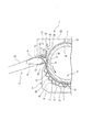
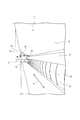
図1〜図4に示すように、加熱ベッド5は、加熱板13と、この加熱板13を支持する側板部14、14と、加熱板13を加熱する加熱部15とを備えている。加熱板13は、長尺状で長手方向Aに対して直交する断面形状が弧状に形成され、凹部2が形成されている。この凹部2は、主ロール7の約半周が収納される半円弧状に形成されている。加熱板13は、弧状の凹部2を上方に向けて、すなわち、表面3を上方に向けて配置され、長手方向Aの両側部が側板部14、14に支持されている。
[Heating bed]
As shown in FIGS. 1 to 4, the
加熱板13の裏面16には、加熱部15が設けられている。加熱部15は、断面が山形形状の複数の通路形成部材28を裏面16に固定して形成されている。複数の通路形成部材28は、その開口部分が加熱板13の裏面16にそれぞれ対向して、裏面16に密着状態で取り付けられている。裏面16と各通路形成部材28とで囲まれた内部に複数の通路17がそれぞれ形成されている。これらの複数の通路17は、隣り合う通路17同士が連通されている。そして、複数の通路17には、高温の蒸気が供給され、複数の通路17内を高温の蒸気が通過することで、高温の蒸気の熱が加熱板13の裏面16側に伝達される。これにより、加熱板13の表面が高温に加熱される。高温の加熱板13の凹部2の表面3上を、リネン品が主ロール7によって押圧されながら搬送される。
A
〔主ロール〕
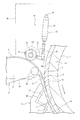
主ロール7は、筒状のロール本体18と、このロール本体18の外周面に設けられた押圧外周19とからなる。この押圧外周19は、フェルト状のパッドが巻き付けられて形成されている。フェルト状のパッドによりリネン品4が加熱板13の凹部2の表面3側へ押圧される。主ロール7のロール本体18には、長手方向Aの両側に回転軸(不図示)が設けられている。これらの回転軸は、主ロール7の軸方向の両側に設けられた支持側部30、30に回転可能に支持されている。
[Main roll]
The
一方の支持側部30内には、主ロール7を一方向に回転駆動する回転駆動部(不図示)が内蔵されている。主ロール7は、回転駆動部からの駆動力により、一方向(リネン品4を搬送する搬送方向)に回転駆動する。主ロール7は、加熱板13の凹部2の表面3との間に、リネン品4が搬送される搬送路6を形成する。この搬送路6内に搬送機構11によって搬送されたリネン品4が入り口8から挿入される。
In one
〔搬送機構] [Transport mechanism]
搬送機構11は、搬送支持台9と、搬送ベルト10と、駆動ローラ20とで構成されている。搬送支持台9は、搬送路6の入り口8に近接して配置されている。この搬送支持台9には、搬送ベルト10が巻き掛けられている。搬送ベルト10は、短冊状の複数本の短冊ベルトによって構成されている。これらの複数本の短冊ベルトが駆動ローラ20にそれぞれ巻き掛けられて搬送ベルト10を形成している。そして、搬送ベルト10は、駆動ローラ20が回転駆動することで移動する。搬送ベルト10が移動することで、搬送ベルト10上に載置されているリネン品4が入り口8から表面3と主ロール7の押圧外周19との間に搬送される。また、入り口8近傍へと搬送されたリネン品4は、押圧ローラ12によって搬送支持台9側へ押圧される。
The
〔押圧ローラ〕
押圧ローラ12は、主ロール7と平行に配置されたローラ21と、このローラ21を搬送支持台9側へ押圧する駆動部22とで形成されている。ローラ21は、少なくとも外周表面が弾性を有する材質、例えばゴムもしくはスポンジによって形成されている。このローラ21は、支持側部30、30にそれぞれ設けられた駆動部22、22(図面では一方の駆動部22のみ図示)によって搬送支持台9に対して接離する。
(Pressing roller)
The
支持側部30、30にそれぞれ設けられた駆動部22、22は、同構成なので、ここでは一方の駆動部22について説明する。図2に示すように、駆動部22は、エアシリンダ25と、押圧レバー23とで形成されている。エアシリンダ25は、後端部24が支持側部30に回動自在に支持されている。押圧レバー23は、エアシリンダ25の駆動軸26の端末26aに一端が回動自在に連結されている。また、押圧レバー23の他端は支持側部30に支持された支持軸27に回動自在に支持されている。同様に、他方の駆動部22も形成されている。駆動部22、22の押圧レバー23、23は、ローラ21の軸方向の両端に設けた支軸21a、21aを回動自在に支持している。
Since the
そして、エアシリンダ25の駆動軸26がシリンダ内に引き込まれた状態(図2において二点鎖線で示す状態)から、駆動軸26がシリンダ外部に突出すると、押圧レバー23が支持軸27を中心に揺動する。押圧レバー23が揺動すると、ローラ21が搬送支持台9から離間した位置から搬送支持台9側に移動する。駆動軸26がシリンダから完全に突出した状態(図2において実線で示す状態)では、ローラ21は、搬送ベルト10上のリネン品4を搬送支持台9上に押圧する。
When the
次に、上記ロール仕上げ機1にリネン品4を搬送する搬送動作について説明する。搬送ベルト10上に載置されたリネン品4は、搬送ベルト10の移動により搬送支持台9上に搬送された後に、搬送路6の入り口8に送られる。その後、搬送路6の入り口8に送られたリネン品4の先端部分(搬送方向の先端側端部)が入り口8から搬送路6内に挿入される。すなわち、リネン品4の先端部分は、主ロール7の押圧外周19と加熱板13の凹部2の表面3との間に挿入される。
Next, a transport operation for transporting the
そして、主ロール7は、加熱板13の表面3へリネン品4を押し付けながら回転する。主ロール7が、リネン品4を加熱板13の表面3へ押し付けながら回転すると、リネン品4は搬送路6内に引き込まれる。リネン品4の先端部が搬送路6内に引き込まれると、エアシリンダ25の駆動軸26がシリンダ内から突出して押圧レバー23を揺動させ、押圧ローラ12を搬送支持台9側へ移動させる。
The
これによりリネン品4が搬送支持台9上へ押圧される。リネン品4が搬送支持台9上へ押圧されると、リネン品4の先端部が主ロール7の回転により搬送路6中を、押圧されながら摺接しつつ搬送される。これにより、押圧ローラ12と搬送路6の入り口8との間でリネン品4には、テンションが付与される。テンションが付与された状態でリネン品4は搬送路6内に挿入され、主ロール7によって表面3側へ押圧されながら摺接しつつ搬送される。主ロール7によって表面3側へ押圧されながら摺接されることでリネン品4のしわが伸ばされアイロニングされる。
As a result, the
以上説明したように、本実施の形態のロール仕上げ機1では、リネン品4の搬送路6の入り口8近傍であって主ロール7に近接して、リネン品4を搬送支持台9側へ押圧する押圧ローラ12が設けられている。このため、リネン品4にテンションを付与した状態で主ロール7と凹型チェスト5との間に搬送できる。特にリネン品4の後端部でのしわの発生を防止することができる。
As described above, in the
また、本実施の形態のロール仕上げ機1では、搬送路6内にリネン品4を搬送させる場合、押圧ローラ12によってリネン品4に常にテンションが付与される。この結果、複数本の主ロール7を用いてリネン品4にテンションを付与する必要がないので、主ロール7の本数を低減することが可能となる。従って、主ロール7を回転駆動するための大きな動力を必要としない。また、大きな動力を必要としないので、ロール仕上げ機自体を小型化することができる。また、大きな動力を必要としないので、主ロール7を回転駆動させるモータが消費する電力を低減することができる。さらに、前段と次段のロールの回転速度を調整する必要がないので、ロールを回転駆動させるモータの回転数の調整が不要になる。
In the
なお、上記実施の形態では、チェスト式のロール仕上げ機に本発明を適用した例を示したが、カレンダ式のロール仕上げ機にも適用することができる。また、上記実施の形態では、押圧ローラ12は、1本のローラを長手方向Aに沿って配置した例を示したが、押圧ローラは、2本以上設けても良く、長手方向Aに沿って、分割した複数のローラを長手方向Aに沿って配置しても良い。さらに、上記実施の形態では、駆動部22としてエアシリンダ25を用いて押圧ローラ12を搬送支持台9に対して接離させている例について説明したが、押圧ローラ12を搬送支持台9に対して接離させる駆動部は他の手段でも良い。
In the above embodiment, an example in which the present invention is applied to a chest type roll finishing machine has been described. However, the present invention can also be applied to a calendar type roll finishing machine. Moreover, in the said embodiment, although the
上述の通り、本発明の実施の形態を開示したが、当業者によっては本発明の範囲を逸脱することなく変更が加えられうることは明白である。すべてのこのような修正及び等価物が次の請求項に含まれることが意図されている。 Although the embodiments of the present invention have been disclosed as described above, it is obvious that those skilled in the art can make changes without departing from the scope of the present invention. All such modifications and equivalents are intended to be included in the following claims.
本発明は、チェスト式のロール仕上げ機の他に、カレンダ式のロール仕上げ機にも利用することができ、いわゆる平物と呼ばれるシーツや、包布、枕カバー等を張力を付与した状態で搬送する装置に利用可能である。 The present invention can be used not only for a chest type roll finishing machine but also for a calendar type roll finishing machine, and transports sheets called so-called flat objects, wrapping cloths, pillow covers, etc. in a tensioned state. It can be used for a device to perform.
1 ロール仕上げ機
2 凹部
3 表面
4 リネン品
5 加熱ベッド
6 搬送路
7 主ロール
8 入り口
9 搬送支持台
10 搬送ベルト
11 搬送機構
12 押圧ローラ
13 加熱板
19 押圧外周
1 Roll finishing machine
DESCRIPTION OF
上記課題を解決するための本発明の一態様は、長尺状で長手方向に対して交差する断面の形状が弧状に形成された凹部の表面上に、洗濯し乾燥した後のリネン品が搬送されこのリネン品を加熱する加熱ベッドと、前記加熱ベッドの前記凹部内に一方向に回転する状態で配置されて前記凹部の表面側との間に前記リネン品が搬送される搬送路を形成し、この搬送路内に搬送された前記リネン品を前記凹部の表面側へ押圧しながら回転することで前記リネン品をプレスする主ロールと、前記搬送路の入り口に配置された搬送支持台とこの搬送支持台に巻き掛けられて前記リネン品を前記搬送路の入り口まで搬送する搬送ベルトとを備えた搬送機構と、を有するロール仕上げ機において、前記搬送路の入り口近傍であって前記主ロールに近接して配置され、前記搬送路の入り口に搬送された前記リネン品を前記搬送支持台側へ押圧する押圧ローラを設け、前記押圧ローラは、前記主ロールと平行に配置された長尺状のローラと、このローラを前記搬送支持台側へ押圧する駆動部と、この駆動部と前記ローラの軸方向端部とを連結し前記駆動部の駆動力で揺動し前記ローラを前記搬送支持台側へ移動させる押圧レバーと、を有することを特徴とする。 One aspect of the present invention for solving the above problems is that a linen product after being washed and dried is conveyed on the surface of a recess having an elongated shape and a cross-sectional shape intersecting the longitudinal direction formed in an arc shape. And a heating path that heats the linen product, and a conveyance path that is arranged in a state of rotating in one direction in the concave portion of the heating bed and that conveys the linen product between the surface side of the concave portion. A main roll that presses the linen product by rotating the linen product conveyed into the conveyance path while pressing the linen product against the surface side of the recess, a conveyance support base disposed at the entrance of the conveyance path, and A roll finishing machine having a conveyance belt that is wound around a conveyance support and conveys the linen product to the entrance of the conveyance path, and is near the entrance of the conveyance path to the main roll. Closely arranged Is, the pressing roller for pressing the linen items conveyed to the inlet of the transport path to the transport support base side is provided, the pressing roller, the parallel-arranged elongated roller and main roll, this A driving unit that presses the roller toward the conveyance support base, and the drive unit and the axial end of the roller are connected to each other, and the roller is moved by the driving force of the driving unit to move the roller toward the conveyance support base. And a pressing lever .
Claims (4)
前記加熱ベッドの前記凹部内に一方向に回転する状態で配置されて前記凹部の表面側との間に前記リネン品が搬送される搬送路を形成し、この搬送路内に搬送された前記リネン品を前記凹部の表面側へ押圧しながら回転することで前記リネン品をプレスする主ロールと、
前記搬送路の入り口に配置された搬送支持台とこの搬送支持台に巻き掛けられて前記リネン品を前記搬送路の入り口まで搬送する搬送ベルトとを備えた搬送機構と、を有するロール仕上げ機において、
前記搬送路の入り口近傍であって前記主ロールに近接して配置され、前記搬送路の入り口に搬送された前記リネン品を前記搬送支持台側へ押圧する押圧ローラを設けたことを特徴とするロール仕上げ機。 A heating bed for transporting the linen product after being washed and dried and heating the linen product on the surface of the recess formed in an arc shape with a cross section intersecting the longitudinal direction in an elongated shape,
The linen that is arranged in the concave portion of the heating bed in a state of rotating in one direction and forms a conveyance path for conveying the linen product between the surface side of the concave part, and the linen that has been conveyed into the conveyance path A main roll that presses the linen product by rotating while pressing the product to the surface side of the recess,
In a roll finishing machine comprising: a transport support provided at an entrance of the transport path; and a transport mechanism including a transport belt wound around the transport support and transporting the linen product to the entrance of the transport path. ,
A pressing roller is provided in the vicinity of the entrance of the transport path and in the vicinity of the main roll, and presses the linen product transported to the entrance of the transport path toward the transport support base. Roll finishing machine.
Priority Applications (1)
| Application Number | Priority Date | Filing Date | Title |
|---|---|---|---|
| JP2016237420A JP6306136B1 (en) | 2016-12-07 | 2016-12-07 | Roll finishing machine |
Applications Claiming Priority (1)
| Application Number | Priority Date | Filing Date | Title |
|---|---|---|---|
| JP2016237420A JP6306136B1 (en) | 2016-12-07 | 2016-12-07 | Roll finishing machine |
Publications (2)
| Publication Number | Publication Date |
|---|---|
| JP6306136B1 JP6306136B1 (en) | 2018-04-04 |
| JP2018089286A true JP2018089286A (en) | 2018-06-14 |
Family
ID=61828521
Family Applications (1)
| Application Number | Title | Priority Date | Filing Date |
|---|---|---|---|
| JP2016237420A Active JP6306136B1 (en) | 2016-12-07 | 2016-12-07 | Roll finishing machine |
Country Status (1)
| Country | Link |
|---|---|
| JP (1) | JP6306136B1 (en) |
Citations (7)
| Publication number | Priority date | Publication date | Assignee | Title |
|---|---|---|---|---|
| US1769009A (en) * | 1928-01-26 | 1930-07-01 | Troy Laundry Machinery Co | Laundry ironing and pressing apparatus |
| US4787157A (en) * | 1985-04-23 | 1988-11-29 | Etablissements Dubix (S.A.) | Dryer and ironer with deformable trough |
| JPH0248097U (en) * | 1988-09-30 | 1990-04-03 | ||
| JPH0271497U (en) * | 1988-11-22 | 1990-05-31 | ||
| US5172502A (en) * | 1991-06-21 | 1992-12-22 | Chicago Dryer Company | Flatwork feeder having flatwork sensing and clamping stations |
| JPH08107995A (en) * | 1994-10-07 | 1996-04-30 | Mitsubishi Heavy Ind Ltd | Roll ironer |
| JP2011129252A (en) * | 2009-12-15 | 2011-06-30 | Sojitz Pla-Net Corp | Heating tool |
-
2016
- 2016-12-07 JP JP2016237420A patent/JP6306136B1/en active Active
Patent Citations (7)
| Publication number | Priority date | Publication date | Assignee | Title |
|---|---|---|---|---|
| US1769009A (en) * | 1928-01-26 | 1930-07-01 | Troy Laundry Machinery Co | Laundry ironing and pressing apparatus |
| US4787157A (en) * | 1985-04-23 | 1988-11-29 | Etablissements Dubix (S.A.) | Dryer and ironer with deformable trough |
| JPH0248097U (en) * | 1988-09-30 | 1990-04-03 | ||
| JPH0271497U (en) * | 1988-11-22 | 1990-05-31 | ||
| US5172502A (en) * | 1991-06-21 | 1992-12-22 | Chicago Dryer Company | Flatwork feeder having flatwork sensing and clamping stations |
| JPH08107995A (en) * | 1994-10-07 | 1996-04-30 | Mitsubishi Heavy Ind Ltd | Roll ironer |
| JP2011129252A (en) * | 2009-12-15 | 2011-06-30 | Sojitz Pla-Net Corp | Heating tool |
Also Published As
| Publication number | Publication date |
|---|---|
| JP6306136B1 (en) | 2018-04-04 |
Similar Documents
| Publication | Publication Date | Title |
|---|---|---|
| US11208757B2 (en) | Method and apparatus for ironing and folding laundry items | |
| CN110382772A (en) | Household compact article folder with stacked conveyor layers and folding method thereof | |
| JP5224796B2 (en) | Roll ironer | |
| JP3138085U (en) | Roll ironer | |
| JP5759732B2 (en) | Belt-type roll ironer | |
| JP6306136B1 (en) | Roll finishing machine | |
| JP2016137242A (en) | Method and apparatus for ironing laundry article | |
| US3577665A (en) | Laundry apparatus | |
| CN206721537U (en) | A kind of tensionless winkler foundation pressure press | |
| JP6306137B1 (en) | Roll finishing machine | |
| JP4558453B2 (en) | Laundry roll finishing machine and method for finishing the roll | |
| JPS5853105B2 (en) | Orimono Amino Touno Lenzokujiyoujiyuusouchi | |
| JP2014023778A (en) | Belt type roll ironer | |
| JP3643618B2 (en) | Roll irona | |
| JP2004180829A (en) | Roller ironer | |
| JP2923213B2 (en) | Roll ironer | |
| JPH046714Y2 (en) | ||
| JP4886267B2 (en) | Belt type roll ironer and tape mark reduction method | |
| JP4007981B2 (en) | Roll ironer | |
| JP5859317B2 (en) | Linen facilities | |
| CN223691467U (en) | Fabric drying device capable of drying on two sides | |
| KR101439525B1 (en) | Automatic iron | |
| CN220115858U (en) | Prevent fold cloth coiling apparatus | |
| JP2013005857A (en) | Calender roll ironer | |
| US3425144A (en) | Feeding apparatus for ironing machines |
Legal Events
| Date | Code | Title | Description |
|---|---|---|---|
| TRDD | Decision of grant or rejection written | ||
| A01 | Written decision to grant a patent or to grant a registration (utility model) |
Free format text: JAPANESE INTERMEDIATE CODE: A01 Effective date: 20180206 |
|
| A61 | First payment of annual fees (during grant procedure) |
Free format text: JAPANESE INTERMEDIATE CODE: A61 Effective date: 20180307 |
|
| R150 | Certificate of patent or registration of utility model |
Ref document number: 6306136 Country of ref document: JP Free format text: JAPANESE INTERMEDIATE CODE: R150 |
|
| R250 | Receipt of annual fees |
Free format text: JAPANESE INTERMEDIATE CODE: R250 |
|
| R250 | Receipt of annual fees |
Free format text: JAPANESE INTERMEDIATE CODE: R250 |
|
| R250 | Receipt of annual fees |
Free format text: JAPANESE INTERMEDIATE CODE: R250 |
|
| R250 | Receipt of annual fees |
Free format text: JAPANESE INTERMEDIATE CODE: R250 |
|
| R250 | Receipt of annual fees |
Free format text: JAPANESE INTERMEDIATE CODE: R250 |
|
| R250 | Receipt of annual fees |
Free format text: JAPANESE INTERMEDIATE CODE: R250 |