JP2018086434A - mattress - Google Patents

mattress Download PDF

Info

Publication number
JP2018086434A
JP2018086434A JP2018032800A JP2018032800A JP2018086434A JP 2018086434 A JP2018086434 A JP 2018086434A JP 2018032800 A JP2018032800 A JP 2018032800A JP 2018032800 A JP2018032800 A JP 2018032800A JP 2018086434 A JP2018086434 A JP 2018086434A
Authority
JP
Japan
Prior art keywords
hardness
mattress
block
end block
user
Prior art date
Legal status (The legal status is an assumption and is not a legal conclusion. Google has not performed a legal analysis and makes no representation as to the accuracy of the status listed.)
Pending
Application number
JP2018032800A
Other languages
Japanese (ja)
Other versions
JP2018086434A5 (en
Inventor
重利 望月
Shigetoshi Mochizuki
重利 望月
宣弘 笹澤
Norihiro Sasazawa
宣弘 笹澤
Current Assignee (The listed assignees may be inaccurate. Google has not performed a legal analysis and makes no representation or warranty as to the accuracy of the list.)
Taika Corp
Original Assignee
Taika Corp
Priority date (The priority date is an assumption and is not a legal conclusion. Google has not performed a legal analysis and makes no representation as to the accuracy of the date listed.)
Filing date
Publication date
Application filed by Taika Corp filed Critical Taika Corp
Priority to JP2018032800A priority Critical patent/JP2018086434A/en
Publication of JP2018086434A publication Critical patent/JP2018086434A/en
Publication of JP2018086434A5 publication Critical patent/JP2018086434A5/ja
Pending legal-status Critical Current

Links

Images

Classifications

    • AHUMAN NECESSITIES
    • A47FURNITURE; DOMESTIC ARTICLES OR APPLIANCES; COFFEE MILLS; SPICE MILLS; SUCTION CLEANERS IN GENERAL
    • A47CCHAIRS; SOFAS; BEDS
    • A47C27/00Spring, stuffed or fluid mattresses or cushions specially adapted for chairs, beds or sofas
    • A47C27/14Spring, stuffed or fluid mattresses or cushions specially adapted for chairs, beds or sofas with foamed material inlays
    • A47C27/15Spring, stuffed or fluid mattresses or cushions specially adapted for chairs, beds or sofas with foamed material inlays consisting of two or more layers
    • AHUMAN NECESSITIES
    • A47FURNITURE; DOMESTIC ARTICLES OR APPLIANCES; COFFEE MILLS; SPICE MILLS; SUCTION CLEANERS IN GENERAL
    • A47CCHAIRS; SOFAS; BEDS
    • A47C27/00Spring, stuffed or fluid mattresses or cushions specially adapted for chairs, beds or sofas
    • A47C27/14Spring, stuffed or fluid mattresses or cushions specially adapted for chairs, beds or sofas with foamed material inlays
    • A47C27/142Spring, stuffed or fluid mattresses or cushions specially adapted for chairs, beds or sofas with foamed material inlays with projections, depressions or cavities
    • A47C27/144Spring, stuffed or fluid mattresses or cushions specially adapted for chairs, beds or sofas with foamed material inlays with projections, depressions or cavities inside the mattress or cushion
    • AHUMAN NECESSITIES
    • A47FURNITURE; DOMESTIC ARTICLES OR APPLIANCES; COFFEE MILLS; SPICE MILLS; SUCTION CLEANERS IN GENERAL
    • A47CCHAIRS; SOFAS; BEDS
    • A47C27/00Spring, stuffed or fluid mattresses or cushions specially adapted for chairs, beds or sofas
    • A47C27/14Spring, stuffed or fluid mattresses or cushions specially adapted for chairs, beds or sofas with foamed material inlays
    • A47C27/148Spring, stuffed or fluid mattresses or cushions specially adapted for chairs, beds or sofas with foamed material inlays of different resilience

Abstract

PROBLEM TO BE SOLVED: To provide a mattress that improves stability for a seated position at an end and stability for rising by additionally eliminating a hardness gap, which is a hardness difference between a mattress peripheral edge part and a flexible mattress central part, while imparting rigidity to the mattress peripheral edge part, and that also has an improved structure for making it easy for a user to turn over on the mattress.SOLUTION: A mattress includes a mattress unit having: a central block disposed in a central part of the mattress in a width direction thereof and supporting at least the back and waist of a user in a supine posture; and end blocks arranged at both ends of the mattress in the width direction and supporting at least shoulder parts of the user in a supine posture. The central block is formed so as to be more flexible than an outer peripheral edge part of each end block. The end block is provided with hardness adjustment means that makes an adjustment so as to form a hardness inclination in which the apparent hardness of the end block gradually decreases in a direction in contact with the center block and the apparent hardness in a part in contact with a shoulder part of the user in a supine posture is lower than the apparent hardness of the central block.SELECTED DRAWING: Figure 1

Description

本発明は、体圧分散性能を有するベッド用マットレスに関し、特に、軽度の要介護者等の使用者が寝返り、起き上り及び離床行動を安定して行うことができる自立支援用のマットレスに関する。   The present invention relates to a mattress for a bed having body pressure dispersion performance, and more particularly, to a mattress for self-support that enables a user such as a light care recipient to turn over and stably perform rising and getting out of bed.

近年、入院患者や要介護者の床ずれの発症を防ぐため、体圧分散機能を高めた床ずれ予防マットレスが種々開発されている。しかしながら、一般的に床ずれ予防マットレスは、所望の体圧分散機能を得るためにマットレス全体が柔らかく形成されており、使用者の体が深く沈み込む傾向にある。それゆえ、起き上り及び離床行動を自力または介護者の補助によって行うことのできる軽度の要介護者がこの種の床ずれ予防マットレスを用いた場合、力が分散してバランスを取り難いために、起き上がりが困難になったり、ベッドの端に腰掛けて足を下ろした体勢(端座位)が不安定になることがあった。   In recent years, various bedsore prevention mattresses having an enhanced body pressure dispersion function have been developed in order to prevent the occurrence of bedsores of hospitalized patients and care recipients. However, in general, the bedsore prevention mattress is formed so that the entire mattress is soft in order to obtain a desired body pressure dispersion function, and the user's body tends to sink deeply. Therefore, if a mild care recipient who can get up and get out of bed on his own or with the help of a caregiver uses this type of mattress prevention mattress, he / she gets up because the power is dispersed and difficult to balance. It became difficult, and the posture (end sitting position) when sitting on the edge of the bed and sitting down was unstable.

そこで特許文献1には、優れた体圧分散性能を有しつつ、マットレス上での起き上がり易さ、端座位の安定感等が良好なマットレスが記載されている。このマットレスは、発泡マット素材からなる表面層・中間層・裏面層を積層して形成されており、このうち中間層はマットレスの短辺方向の周縁部に硬質部材が配され、中心部には軟質部材が配された構造であり、各層の硬度が硬質部材>裏面層>表面層及び/又は軟質部材の硬度関係を有しつつ、硬質部材と軟質部材の接触面は裏面層の中心に向けて傾斜角度25〜50度に傾斜している。   Therefore, Patent Document 1 describes a mattress that has excellent body pressure dispersion performance, and that is easy to get up on the mattress and has a good sense of stability in the sitting position. This mattress is formed by laminating a surface layer, an intermediate layer, and a back layer made of foamed mat material. Among these layers, the intermediate layer has a hard member arranged at the peripheral edge in the short side direction of the mattress and has a central portion. A structure in which soft members are arranged, and the hardness of each layer has a hardness relationship of hard member> back surface layer> surface layer and / or soft member, and the contact surface of the hard member and the soft member is directed toward the center of the back surface layer Is inclined at an inclination angle of 25 to 50 degrees.

特許第4881667号Japanese Patent No. 4881667

上述した特許文献1のマットレスでは、マットレス周縁部に硬質部材が配されているため、使用者がこの周縁部に手や肘を付いて起き上がろうとした際にバランスが取りやすく、起き上がり動作が安定する。そして、硬質部材で形成されたマットレス周縁部とマットレス中心部の軟質部材との接触面に所定角度の傾斜構造を設けることにより、硬質部材と軟質部材の接触部分の硬さの差(硬度ギャップ)を解消し、端座位の安定性も向上させている。しかしながら、例えば中間層を構成する両部材の厚みを薄く構成しようとすると傾斜構造部分も小さくなるため、硬度ギャップの解消が充分でなくなるおそれがあった。また、端座位において深く腰掛けると使用者の臀部が傾斜構造部分を乗り越えることがあり、そのような場合に後方に重心を移動させると、硬度ギャップによって端座位安定性が乱れることがあった。そのため、さらなる硬度ギャップの解消による端座位安定性が求められていた。   In the mattress of Patent Document 1 described above, since a hard member is arranged on the periphery of the mattress, when the user tries to get up with a hand or an elbow on the periphery, the balance is easily obtained and the rising operation is stabilized. . Then, by providing an inclined structure of a predetermined angle on the contact surface between the mattress peripheral portion formed of the hard member and the soft member at the center of the mattress, the difference in hardness between the contact portions of the hard member and the soft member (hardness gap) The stability of the end sitting position is improved. However, for example, if the thickness of both members constituting the intermediate layer is made thin, the inclined structure portion also becomes small, so there is a possibility that the elimination of the hardness gap may not be sufficient. Further, if the user sits deeply in the end sitting position, the user's buttocks may get over the inclined structure portion. In such a case, if the center of gravity is moved backward, the end sitting position stability may be disturbed by the hardness gap. Therefore, end sitting position stability by eliminating the hardness gap has been demanded.

他方、マットレス上での起き上がり及び離床行動にあたっては、まず、マットレスに仰向けで寝た体勢(仰臥位)から、横向きで寝た体勢(側臥位)に姿勢を変えること、すなわち、寝返りが必要となる。上述の特許文献1においては、マットレス上での起き上がり易さが高められたマットレスの構造については記載されているものの、寝返りし易いマットレスの構造に関する検討はなされていなかった。   On the other hand, when getting up and getting out of bed on the mattress, it is first necessary to change the posture from the posture of lying on the mattress (the supine position) to the posture of lying on the side (the lying position), that is, to turn over. . In the above-mentioned Patent Document 1, although the structure of the mattress that is easy to get up on the mattress is described, the structure of the mattress that easily turns over has not been studied.

したがって、本発明は上述した点に鑑みてなされたもので、その目的は、マットレス周縁部に剛性を持たせながらも、マットレス周縁部と柔軟なマットレス中心部の硬さの差である硬度ギャップをさらに解消して端座位安定性や起き上がり安定性を高めると共に、寝返り容易性も高めた構造のマットレスを提供することにある。   Accordingly, the present invention has been made in view of the above-described points, and the object thereof is to provide a hardness gap that is a difference in hardness between the mattress peripheral portion and the flexible mattress central portion while providing rigidity to the mattress peripheral portion. It is another object of the present invention to provide a mattress having a structure in which the stability of the end-sitting position and the rising stability is improved and the ease of turning over is improved.

本発明者らは、上記課題を解決すべく鋭意検討した結果、以下のことを見出した。仰臥位から側臥位に寝返りするにあたっては、頭部の旋回→体幹の旋回→骨盤の旋回の動作が行われる。このうち、体幹の旋回において、特に肩部の旋回動作は寝返りを成功させる重要なポイントであり、肩部の旋回動作が妨げられず、旋回しやすい状態とすることにより、寝返りも容易となりやすい。そこで、寝返り方向の肩部や上腕部を選択的にマットレスに沈み込ませるようにすることによって、マットレスに入り込んだ肩部が寝返りの回転軸となり寝返りが促進されることがわかった。この知見に基づき、本発明を完成するに至った。   As a result of intensive studies to solve the above problems, the present inventors have found the following. When turning from the supine position to the recumbent position, the operation of turning the head → turning the trunk → turning the pelvis is performed. Of these, in the turning of the trunk, especially the turning motion of the shoulder is an important point for successful turning over, and the turning operation of the shoulder is not hindered and it is easy to turn, so it is easy to turn over. . Thus, it has been found that by selectively sinking the shoulder portion and upper arm portion in the turning direction into the mattress, the shoulder portion that has entered the mattress serves as a rotation axis for turning over and promotes turning over. Based on this finding, the present invention has been completed.

上記課題を解決するため、本発明のマットレスは、マットレスの幅方向の中央部に配置され、仰臥姿勢の使用者の少なくとも背中及び腰(臀部及び仙骨部含む)を支持する中央ブロックと、マットレスの幅方向の両端部に配置され、仰臥姿勢の使用者の少なくとも肩部を支持する端部ブロックと、を有するマットレスユニットを含むマットレスであって、中央ブロックは、端部ブロックの外方周縁部よりも柔軟に形成されており、端部ブロックには、中央ブロックと接する方向に向かって、その見かけの硬度が漸次低くなる硬度勾配が形成されるように調整すると共に、仰臥姿勢の使用者の肩部と接する位置の見かけの硬度が中央ブロックの見かけの硬度よりも低くなるように調整する硬度調整手段が設けられている。   In order to solve the above problems, the mattress of the present invention is arranged at the center in the width direction of the mattress, and supports at least the back and waist (including the buttocks and sacrum) of the user in the supine posture, and the width of the mattress A mattress unit including a mattress unit disposed at both ends in a direction and supporting at least a shoulder of a user in a supine posture, wherein the central block is more than the outer peripheral edge of the end block. The end block is adjusted to form a hardness gradient in which the apparent hardness gradually decreases in the direction of contact with the central block, and the shoulder of the user in the supine posture Hardness adjusting means for adjusting the apparent hardness at the position in contact with the central block to be lower than the apparent hardness of the central block is provided.

端部ブロックに上述の硬度調整手段を設けることにより、中央ブロックと接する方向に向かって、端部ブロックの見かけの硬度が徐々に小さくなるため、柔軟な中央ブロックと硬質な端部ブロックの外方周縁部との硬さの差である硬度ギャップが解消される。また、硬度調整手段により、端部ブロックの仰臥姿勢の使用者の肩部と接する位置の見かけの硬度が、柔軟な中央ブロックの見かけの硬度よりも低くなるように調整されているため、寝返り方向にある使用者の肩部や上腕部が端部ブロックの低硬度に調整された部分に選択的に沈み込みやすくなり、その部分に沈み込んだ肩部が寝返りの回転軸となり寝返りが促進される。なお、本明細書において、中央ブロック及び端部ブロックの「ブロック」とは、マットレスユニットにおける区画(領域)のことをいう。   By providing the above-mentioned hardness adjusting means on the end block, the apparent hardness of the end block gradually decreases in the direction in contact with the center block, so the outer side of the flexible center block and the hard end block The hardness gap, which is the difference in hardness from the peripheral edge, is eliminated. In addition, since the apparent hardness of the position of the end block in contact with the shoulder of the user in the supine posture of the end block is adjusted to be lower than the apparent hardness of the flexible central block, the roll-up direction The user's shoulder and upper arm can easily sink into the part of the end block that has been adjusted to a low hardness, and the shoulder that sinks into that part becomes the axis of rotation for turning over and promotes turning over. . In the present specification, “blocks” of the central block and the end block refer to sections (regions) in the mattress unit.

また、本発明の硬度調整手段は、端部ブロックの上面又は下面に形成された複数の凹溝であり、複数の凹溝はマットレスの長手方向に配列され、中央ブロックと接する方向に向かって、各凹溝の空隙体積が漸次増加するように形成された配列領域を有し、仰臥姿勢の使用者の肩部と接する位置と対応する部分に、少なくとも、複数の凹溝のうち空隙体積が最も大きい凹溝が配置されていることも好ましい。端部ブロックに、各凹溝の空隙体積が漸次増加するように複数の凹溝を形成することにより、端部ブロックの見かけの硬度が漸次低くなる硬度勾配が形成され、柔軟な中央ブロックと硬質な端部ブロックの外方周縁部との硬さの差である硬度ギャップが解消される。また、端部ブロックの仰臥姿勢の使用者の肩部と接する位置と対応する部分に形成する凹溝の空隙体積を他の部分よりも大きくすることにより、使用者の肩部と接する部分の見かけの硬度が他の部分及び中央ブロックよりも小さくなるため、寝返り方向にある使用者の肩部や上腕部が端部ブロックに選択的に沈み込みやすくなり、端部ブロックに入り込んだ肩部が寝返りの回転軸となり寝返りが促進される。   Further, the hardness adjusting means of the present invention is a plurality of grooves formed on the upper surface or the lower surface of the end block, the plurality of grooves are arranged in the longitudinal direction of the mattress, toward the direction in contact with the central block, It has an array region formed so that the void volume of each concave groove gradually increases, and at least the void volume among the plurality of concave grooves is the portion corresponding to the position in contact with the shoulder of the user in the supine posture. It is also preferable that a large concave groove is arranged. By forming a plurality of grooves in the end block so that the void volume of each groove gradually increases, a hardness gradient is formed in which the apparent hardness of the end block gradually decreases, and a flexible central block and a hard block are formed. The hardness gap, which is the difference in hardness from the outer peripheral edge of the end block, is eliminated. Also, by making the void volume of the groove formed in the part corresponding to the position of the end block in the supine posture in contact with the shoulder of the user larger than the other part, the appearance of the part in contact with the shoulder of the user Since the hardness of the arm is smaller than the other parts and the central block, the shoulder and upper arm of the user in the turning direction can easily sink into the end block, and the shoulder that has entered the end block is turned over. It becomes the axis of rotation and the rollover is promoted.

また、上述の凹溝の空隙体積の増加は、溝深さの増大、溝幅の拡大又はこれらの組み合わせにより行われることも好ましい。これにより、好適な凹溝の空隙体積の増加手段が選択される。   The increase in the void volume of the concave groove is preferably performed by increasing the groove depth, increasing the groove width, or a combination thereof. Thereby, a suitable means for increasing the void volume of the groove is selected.

また、本発明の硬度調整手段は、端部ブロックの上面又は下面に形成された複数の凹溝であり、複数の凹溝はマットレスの長手方向に配列され、中央ブロックと接する方向に向かって、隣接する凹溝と凹溝との間隔が漸次狭くなるように形成された配列領域を有し、仰臥姿勢の使用者の肩部と接する位置と対応する部分における、隣接する凹溝と凹溝との間隔の平均値が、他の部分における平均値よりも小さくなるように凹溝が配置されていることも好ましい。端部ブロックに、凹溝間の間隔が漸次狭くなるように複数の凹溝を配置することにより、端部ブロックの見かけの硬度が漸次低くなる硬度勾配が形成され、柔軟な中央ブロックと硬質な端部ブロックの外方周縁部との硬さの差である硬度ギャップが解消される。また、端部ブロックの仰臥姿勢の使用者の肩部と接する位置と対応する部分の凹溝間の間隔を他の部分の間隔より小さくすることにより、使用者の肩部と接する部分の見かけの硬度が他の部分及び中央ブロックよりも小さくなるため、寝返り方向にある使用者の肩部や上腕部が端部ブロックに選択的に沈み込みやすくなり、端部ブロックに入り込んだ肩部が寝返りの回転軸となり寝返りが促進される。なお、凹溝には、溝幅が極端に小さい形態(例えば、ハーフカット加工による切り込み)も含まれる。   Further, the hardness adjusting means of the present invention is a plurality of grooves formed on the upper surface or the lower surface of the end block, the plurality of grooves are arranged in the longitudinal direction of the mattress, toward the direction in contact with the central block, The adjacent concave groove and the concave groove in a portion corresponding to a position in contact with the shoulder portion of the user in the supine posture, having an array region formed so that the interval between the adjacent concave grooves is gradually narrowed. It is also preferable that the concave grooves are arranged so that the average value of the intervals is smaller than the average value in other portions. By arranging a plurality of concave grooves in the end block so that the interval between the concave grooves is gradually narrowed, a hardness gradient is formed in which the apparent hardness of the end block gradually decreases, and a flexible central block and a hard block are formed. A hardness gap, which is a difference in hardness from the outer peripheral edge of the end block, is eliminated. In addition, by making the interval between the concave grooves in the portion corresponding to the position of the end block in the supine posture in contact with the shoulder of the user smaller than the interval of the other portions, the appearance of the portion in contact with the user's shoulder Because the hardness is smaller than the other parts and the central block, the shoulder and upper arm of the user in the turning direction can easily sink into the end block, and the shoulder that has entered the end block can be turned over. It becomes a rotating shaft, and rolling over is promoted. Note that the groove includes a form in which the groove width is extremely small (for example, cutting by half-cut processing).

また、本発明の硬度調整手段は、端部ブロックの厚み方向に形成された複数の貫通孔であり、この複数の貫通孔の配置は、中央ブロックと接する方向に向かって、貫通孔の空隙容積または個数の少なくとも一方が漸次変化するように形成された領域を有し、仰臥姿勢の使用者の肩部と接する位置と対応する部分に、少なくとも、複数の貫通孔のうち空隙容積が最も大きい貫通孔が配置されているか、隣接する貫通孔と貫通孔との間隔の平均値が、他の部分における平均値よりも小さくなるように貫通孔が配置されていることも好ましい。端部ブロックに、中央ブロックと接する方向に向かって、貫通孔の径が漸次大きくなるように貫通孔を配置させるか、貫通孔の個数が漸次増加するように貫通孔を配置させるか、またはこれらを組み合わせることにより、端部ブロックの見かけの硬度が漸次低くなる硬度勾配が形成され、柔軟中央ブロックと硬質な端部ブロックの外方周縁部との硬さの差である硬度ギャップが解消される。また、端部ブロックの仰臥姿勢の使用者の肩部と接する位置と対応する部分に、空隙容積が最も大きい貫通孔を配置させるか、隣接する貫通孔の間隔を他の部分の間隔より小さくするか、またはこれらを組み合わせることにより、使用者の肩部と接する部分の見かけの硬度が他の部分及び中央ブロックよりも小さくなるため、寝返り方向にある使用者の肩部や上腕部が端部ブロックに選択的に沈み込みやすくなり、端部ブロックに入り込んだ肩部が寝返りの回転軸となり寝返りが促進される。なお、貫通孔には、端部ブロックを厚み方向に貫通する切り込み形態も含まれる。   Further, the hardness adjusting means of the present invention is a plurality of through holes formed in the thickness direction of the end block, and the arrangement of the plurality of through holes is a void volume of the through hole toward the direction in contact with the central block. Or at least one of the plurality of through-holes having a region that is formed so that at least one of the numbers gradually changes and corresponding to a position in contact with the shoulder portion of the user in the supine posture. It is also preferred that the through holes are arranged such that the holes are arranged or the average value of the interval between the adjacent through holes is smaller than the average value in the other portions. In the end block, the through holes are arranged so that the diameter of the through holes gradually increases toward the direction in contact with the central block, or the through holes are arranged so that the number of through holes gradually increases, or these Are combined to form a hardness gradient in which the apparent hardness of the end block gradually decreases, and the hardness gap that is the difference in hardness between the flexible central block and the outer peripheral edge of the hard end block is eliminated. . In addition, a through hole having the largest void volume is arranged in a portion corresponding to the position of the end block in the supine posture contacting the user's shoulder or the interval between adjacent through holes is made smaller than the interval between other portions. Or, by combining them, the apparent hardness of the part in contact with the user's shoulder is smaller than the other parts and the central block, so the user's shoulder and upper arm in the turning direction are end blocks It is easy to selectively sink, and the shoulder part that has entered the end block serves as a rotation axis for turning over, thereby promoting turning over. Note that the through-hole includes a cut form that penetrates the end block in the thickness direction.

また、本発明のマットレスユニットの中央ブロックは、第1のクッション材で形成されており、端部ブロックは第1のクッション材よりも硬質な第2のクッション材で形成されていることも好ましい。これにより、マットレスユニットを構成する各ブロックに適した硬度等の物性や仕様を備えた材料をそれぞれ選択することができる。   Moreover, it is also preferable that the center block of the mattress unit of the present invention is formed of a first cushion material, and the end block is formed of a second cushion material harder than the first cushion material. Thereby, materials having physical properties such as hardness and specifications suitable for each block constituting the mattress unit can be selected.

また、本発明の端部ブロックを形成する第2のクッション材の硬度(JIS K6401「耐荷重用軟質ポリウレタンフォーム」準拠)が180〜440Nであり、第1のクッション材の硬度に対する第2のクッション材の硬度比(JIS K6401「耐荷重用軟質ポリウレタンフォーム」に準拠して測定された硬度の比)が1.8〜6.5であることも好ましい。これにより、第1のクッション材及び第2のクッション材の好適な硬度範囲が選択される。   The second cushion material forming the end block of the present invention has a hardness (compliant with JIS K6401 “soft polyurethane foam for load bearing”) of 180 to 440 N, and the second cushion material with respect to the hardness of the first cushion material. It is also preferable that the hardness ratio (the ratio of hardness measured according to JIS K6401 “soft polyurethane foam for load bearing”) is 1.8 to 6.5. Thereby, the suitable hardness range of a 1st cushion material and a 2nd cushion material is selected.

また、本発明の第1のクッション材及び第2のクッション材は、それぞれが、樹脂発泡体、三次元網状構造体及び綿成形体からなる群から選択される1種以上の材料であることも好ましい。これにより、第1のクッション材及び第2のクッション材を構成する好適な材料が選択される。これらの材料は成形性に優れ、軽量であり、前述した硬度調整手段を安定して形成することができる。   In addition, each of the first cushion material and the second cushion material of the present invention may be one or more materials selected from the group consisting of a resin foam, a three-dimensional network structure, and a cotton molded body. preferable. Thereby, the suitable material which comprises a 1st cushion material and a 2nd cushion material is selected. These materials are excellent in moldability, are lightweight, and can form the above-described hardness adjusting means stably.

また、本発明のマットレスユニットの中央ブロックと端部ブロックは、同じクッション材で形成されており、中央ブロックには、その見かけの硬度が端部ブロックの外方周縁部の見かけの硬度よりも低くなるように調整する第2の硬度調整手段が設けられていることも好ましい。これにより、マットレスユニットを1種類のクッション材で形成することができる。   Further, the center block and the end block of the mattress unit of the present invention are formed of the same cushion material, and the apparent hardness of the center block is lower than the apparent hardness of the outer peripheral edge of the end block. It is also preferable that a second hardness adjusting means for adjusting so as to be provided. Thereby, a mattress unit can be formed with one kind of cushioning material.

また、中央ブロックに設けられた第2の硬度調整手段は、中央ブロックの上面又は下面に形成された複数のスリット、貫通孔、若しくは溝であることも好ましい。これにより、好適な硬度調整手段の態様が選択される。   The second hardness adjusting means provided in the central block is preferably a plurality of slits, through holes, or grooves formed on the upper surface or the lower surface of the central block. Thereby, the suitable aspect of a hardness adjustment means is selected.

また、マットレスユニットの中央ブロックと端部ブロックとが、同一のクッション材で形成されている場合において、このクッション材は、樹脂発泡体、三次元網状構造体又は綿成形体であることも好ましい。これにより、マットレスユニットを構成する好適な材料が選択される。これらの材料は成形性に優れ、軽量であり、前述した硬度調整手段を安定して形成することができる。   Further, when the central block and the end block of the mattress unit are formed of the same cushion material, the cushion material is preferably a resin foam, a three-dimensional network structure, or a cotton molded body. Thereby, the suitable material which comprises a mattress unit is selected. These materials are excellent in moldability, are lightweight, and can form the above-described hardness adjusting means stably.

また、本発明のマットレスユニットは、クッション材で形成された下層の上に積層されており、この下層の上面又は下面にはマットレスの幅方向に配列された複数の下層溝が設けられていることも好ましい。これにより、使用者の体がクッション材で形成された下層に安定的に支持されると共に、下層に施された複数の下層溝によって、背上げ又は膝上げ等のギャッジアップに追従した変形を容易とすることができる。   The mattress unit of the present invention is laminated on a lower layer formed of a cushion material, and a plurality of lower layer grooves arranged in the width direction of the mattress are provided on the upper surface or the lower surface of the lower layer. Is also preferable. As a result, the user's body is stably supported by the lower layer formed of the cushioning material, and the lower layer or the lower layer groove formed on the lower layer facilitates deformation following back-up or knee-up, etc. It can be.

また、上述の下層の上面には下層溝が設けられており、マットレスユニットの端部ブロックの下面には凹溝が設けられていることも好ましい。このように、下層溝と凹溝が対面して設けられることにより、下層溝と凹溝とが対向する対面部がマットレス内部で選択的に変形し易くなるため、マットレスユニットの作用効果を部分的に一層向上させることができる。   Further, it is also preferable that a lower layer groove is provided on the upper surface of the lower layer and a concave groove is provided on the lower surface of the end block of the mattress unit. As described above, since the lower layer groove and the concave groove are provided to face each other, the facing portion where the lower layer groove and the concave groove face is easily selectively deformed inside the mattress. Can be further improved.

また、上述の下層を形成するクッション材は、樹脂発泡体、三次元網状構造体及び綿成形体からなる群から選択される1種以上の材料であることも好ましい。これにより、下層のクッション材を構成する好適な材料が選択される。   The cushion material forming the lower layer is preferably one or more materials selected from the group consisting of a resin foam, a three-dimensional network structure, and a cotton molded body. Thereby, the suitable material which comprises the cushion material of a lower layer is selected.

本発明によれば、以下のような優れた効果を有するマットレスを提供することができる。
(1)本発明の硬度調整手段により、硬質なマットレス周縁部と柔軟なマットレス中心部の硬さの差である硬度ギャップが充分に解消されているため、端座位安定性や起き上がり安定性が高く、軽度の要介護者等の使用者が起き上り及び離床行動を自立して行うことができる。
(2)使用者の肩部や上腕部が選択的にマットレスの低硬度に調整された部分に沈み込むため、マットレスに入り込んだ肩部が寝返りの回転軸となり寝返りが促進される。
(3)硬度調整手段が端部ブロックに複数の凹溝を施すことによって得られるため、マットレスをシンプルな構造とすることができ、製造も容易とすることができる。
According to the present invention, a mattress having the following excellent effects can be provided.
(1) The hardness adjustment means of the present invention sufficiently eliminates the hardness gap, which is the difference in hardness between the hard mattress peripheral edge and the flexible mattress center, so that the edge sitting stability and rising stability are high. Users such as mild care recipients can stand up and get out of bed.
(2) Since the user's shoulder and upper arm are selectively sunk into a portion of the mattress that has been adjusted to have a low hardness, the shoulder that has entered the mattress serves as a rotation axis for turning over and the turning over is promoted.
(3) Since the hardness adjusting means is obtained by forming a plurality of concave grooves in the end block, the mattress can have a simple structure and can be manufactured easily.

第1の実施形態に係るマットレスの(a)分解斜視図、(b)幅方向の側面図及び(c)長手方向の側面図である。It is the (a) disassembled perspective view of the mattress which concerns on 1st Embodiment, (b) The side view of the width direction, and (c) The side view of a longitudinal direction. 第1の実施形態に係るマットレスの中層に位置するマットレスユニットの(a)上面側を示す図及び(b)下面側を示す図である。It is a figure which shows the (a) upper surface side and (b) lower surface side of the mattress unit located in the middle layer of the mattress which concerns on 1st Embodiment. マットレスユニットにおける仰臥姿勢の使用者の肩部と接する位置の範囲を示す図である。It is a figure which shows the range of the position which touches the user's shoulder part of the supine posture in a mattress unit. 第1の実施形態に係るマットレスの幅方向の側面図及びその部分拡大図である。It is the side view of the width direction of the mattress which concerns on 1st Embodiment, and its partial enlarged view. マットレス幅方向の位置と、マットレスユニットの見かけの硬度との関係を示すグラフである。It is a graph which shows the relationship between the position of a mattress width direction, and the apparent hardness of a mattress unit. 第1の実施形態に係るマットレスの長手方向の側面図とその部分拡大図である。It is the side view of the longitudinal direction of the mattress which concerns on 1st Embodiment, and its partial enlarged view. 第1の実施形態に係るマットレスの下層の上面側を示す図である。It is a figure which shows the upper surface side of the lower layer of the mattress which concerns on 1st Embodiment. 本発明のマットレスユニットの見かけ硬度の測定方法を説明する図である。It is a figure explaining the measuring method of the apparent hardness of the mattress unit of this invention. 第2の実施形態に係るマットレスを示す分解斜視図である。It is a disassembled perspective view which shows the mattress which concerns on 2nd Embodiment. 第2の実施形態に係るマットレスの幅方向の側面図及びその部分拡大図である。It is the side view of the width direction of the mattress which concerns on 2nd Embodiment, and its partial enlarged view. 第3の実施形態に係るマットレスユニットの(a)端部ブロックにおける貫通孔の配置を示す図及び(b)図11(a)のA−A線断面図とその部分拡大図である。It is the figure which shows arrangement | positioning of the through-hole in the (a) end block of the mattress unit which concerns on 3rd Embodiment, (b) The sectional view on the AA line of FIG. 第3の実施形態に係るマットレスユニットの端部ブロックに設けられた貫通孔の他の配置例を示す図である。It is a figure which shows the other example of arrangement | positioning of the through-hole provided in the edge part block of the mattress unit which concerns on 3rd Embodiment. 第4の実施形態に係るマットレスの(a)分解斜視図、(b)幅方向の側面図及び(c)長手方向の側面図である。It is the (a) disassembled perspective view of the mattress which concerns on 4th Embodiment, (b) The side view of the width direction, and (c) The side view of a longitudinal direction. 第4の実施形態に係るマットレスユニットの(a)上面側を示す図及び(b)下面側を示す図である。(A) The figure which shows the upper surface side of the mattress unit which concerns on 4th Embodiment, (b) The figure which shows the lower surface side.

図1に示すように、本発明の第1の実施形態にかかるマットレス1は、表面層8と、中間層のマットレスユニット4と、下層6とが積層されて構成されている。なお、本明細書において上下とは、マットレス1を寝台や床に設置して使用する状態での上下方向、すなわち、図1における上下方向をいうものとする。   As shown in FIG. 1, the mattress 1 according to the first embodiment of the present invention is configured by laminating a surface layer 8, an intermediate mattress unit 4, and a lower layer 6. In the present specification, the term “up and down” refers to the up and down direction in a state where the mattress 1 is installed on a bed or a floor, that is, the up and down direction in FIG.

まず、本実施形態にかかるマットレス1を構成するマットレスユニット4について説明する。図2に示すように、本実施形態におけるマットレスユニット4は、マットレスの幅方向の中央部に配置された中央ブロック2と、その両側に配置された2つの端部ブロック3とから構成されている。本実施形態においては、後述するように、中央ブロック2と端部ブロック3とは異なるクッション材で形成されている。そのため、中央ブロック2と端部ブロック3とは、両者の配置がずれないように、両者の隣接面において接着剤等で固定されていてもよいし、下層6及び表面層8に接着剤等でそれぞれ固定されていてもよい。   First, the mattress unit 4 constituting the mattress 1 according to the present embodiment will be described. As shown in FIG. 2, the mattress unit 4 in the present embodiment includes a central block 2 disposed at the center portion in the width direction of the mattress and two end blocks 3 disposed on both sides thereof. . In this embodiment, as will be described later, the central block 2 and the end block 3 are formed of different cushion materials. Therefore, the central block 2 and the end block 3 may be fixed with an adhesive or the like on the adjacent surfaces of the both so that the arrangement of the two does not shift, or the lower block 6 and the surface layer 8 with an adhesive or the like. Each may be fixed.

図3に示すように、マットレスユニット4の中央ブロック2は、仰臥姿勢の使用者Bの体のうち、少なくとも背中及び腰(臀部及び仙骨部含む)を支持するように構成されている。本実施形態における中央ブロック2は、幅方向の長さが31cm、長手方向の長さが191cm、厚みが3cmの大きさに形成されており、仰臥姿勢の使用者Bの体の中心部分、すなわち、頭、背中、腰及び下肢を支持することができる。中央ブロックの幅方向の長さは、後述するように、仰臥姿勢の使用者の肩部と接する位置S(マットレスの幅方向の中心から幅方向の一端に向かって11cm〜25cmの間の領域)が端部ブロック3上に配置されている必要がある関係から、中央ブロックの幅方向の長さは50cm未満であり、40cm以下であることが好ましく、32cm以下であることがより好ましい。中央ブロック2はその両側に配置された端部ブロックの外方周縁部3aよりも柔軟に形成されており、本実施形態においては、中央ブロック2は、端部ブロック3を形成する第2のクッション材よりも柔軟な第1のクッション材で形成されている。それゆえ、中央ブロック2は体圧分散性に優れ、中央ブロック2に接する使用者Bの体を柔軟に支持することができる。第1のクッション材としては、JIS K6401「耐荷重用軟質ポリウレタンフォーム」に準拠して測定された硬度が、50〜160Nであるものが好ましく、70〜150Nであるものがより好ましく、90〜140Nであるものが特に好ましい。第1のクッション材としては、上述した硬度を有し、クッション性を有するものであれば特に限定されないが、樹脂発泡体、三次元網状構造体及び綿成形体が好適に用いられ、取り扱い及び加工のしやすさの観点から、樹脂発泡体がより好ましい。樹脂発泡体として、具体的には、発泡ポリウレタン、発泡ポリオレフィン又は発泡シリコーン等が挙げられる。なお、中央ブロック2の上に体圧分散性を有する表面層8が積層される場合には、必ずしも中央ブロック2は体圧分散性を有する硬度でなくてもよく、上述した範囲外の硬度を有するクッション材を用いることもできる。また、第1のクッション材として、空気や液体を合成樹脂やゴム材からなる袋に充填し、密閉したエアセル等の流体充填構造体を適用してもよい。   As shown in FIG. 3, the central block 2 of the mattress unit 4 is configured to support at least the back and waist (including the buttocks and sacrum) of the body of the user B in the supine posture. The central block 2 in this embodiment is 31 cm in length in the width direction, 191 cm in length in the longitudinal direction, and 3 cm in thickness, and is the central part of the body of the user B in the supine position, that is, Can support the head, back, waist and lower limbs. The length in the width direction of the central block is, as will be described later, a position S in contact with the shoulder portion of the user in the supine posture (region between 11 cm and 25 cm from the center in the width direction of the mattress toward one end in the width direction). Therefore, the length of the central block in the width direction is less than 50 cm, preferably 40 cm or less, and more preferably 32 cm or less. The central block 2 is formed more flexibly than the outer peripheral edge 3a of the end block disposed on both sides thereof. In the present embodiment, the central block 2 is a second cushion that forms the end block 3. The first cushion material is softer than the material. Therefore, the central block 2 is excellent in body pressure dispersibility and can flexibly support the user B's body in contact with the central block 2. As the first cushion material, one having a hardness measured in accordance with JIS K6401 “soft polyurethane foam for load bearing” is preferably 50 to 160 N, more preferably 70 to 150 N, and 90 to 140 N. Some are particularly preferred. The first cushion material is not particularly limited as long as it has the above-mentioned hardness and cushioning properties, but a resin foam, a three-dimensional network structure, and a cotton molded body are preferably used, and are handled and processed. From the viewpoint of ease of handling, a resin foam is more preferable. Specific examples of the resin foam include foamed polyurethane, foamed polyolefin, and foamed silicone. In addition, when the surface layer 8 which has a body pressure dispersibility is laminated | stacked on the center block 2, the center block 2 does not necessarily need the hardness which has a body pressure dispersibility, and hardness outside the range mentioned above. The cushion material which has can also be used. Further, as the first cushion material, a fluid-filled structure such as an air cell filled with air or liquid in a bag made of a synthetic resin or rubber material may be applied.

図3に示すように、マットレスユニット4の端部ブロック3は、仰臥姿勢の使用者Bの体のうち、少なくとも肩部を支持するように構成されている。本実施形態における端部ブロック3の各々は、中央ブロック2とは別体で形成され、幅方向の長さが30cm、長手方向の長さが191cm、厚みが3cmの大きさに形成されており、仰臥姿勢の使用者Bの体の肩部及び腕を支持することができる。端部ブロック3は、隣接した中央ブロック2を形成する第1のクッション材よりも硬質な第2のクッション材で形成されている。それゆえ、端部ブロック3では、使用者が手をついたり座ったときの荷重(押しつけ力)に対する反発力が大きいため踏ん張りが効きバランスがとりやすく、端座位安定性及び起き上がり安定性を有する。   As shown in FIG. 3, the end block 3 of the mattress unit 4 is configured to support at least a shoulder portion of the body of the user B in a supine posture. Each of the end blocks 3 in the present embodiment is formed separately from the central block 2 and has a width of 30 cm, a length of 191 cm, and a thickness of 3 cm. It is possible to support the shoulder and arm of the body of the user B in the supine posture. The end block 3 is formed of a second cushion material that is harder than the first cushion material that forms the adjacent central block 2. Therefore, the end block 3 has a large repulsive force against the load (pressing force) when the user puts his hand or sits down, so that the struts are effective and balanced, and has end-sitting position stability and rising stability.

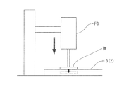
図1〜図5に示すように、本実施形態における端部ブロック3には4つの凹溝5a〜5dからなる硬度調整手段5が設けられている。この硬度調整手段5によって、端部ブロック3は、中央ブロック2と接する方向に向かって、すなわち、マットレスの幅方向の中心に向かって、その見かけの硬度が漸次低くなる硬度勾配が形成されるように調整されている。ここで、本明細書における「見かけの硬度」とは、端部ブロック3及び中央ブロック2を形成するクッション材の素材自体の硬度ではなく、マットレスユニット4の形態で測定した硬度、すなわち、中央ブロック2及び硬度調整手段5が設けられている端部ブロック3そのものを測定した硬度であって、端部ブロック3及び中央ブロック2を厚み方向(下方向)に所定面積で加圧し、押圧変形させた時の反発力として求められる、測定部分における硬度のことをいう。具体的には、「見かけの硬度」は、図8に示すように、φ40mm×厚み1.6mmの円形のアルミ製加圧子INを直接、中央ブロック2又は端部ブロック3の上面の測定部分に当接させ、各ブロックの厚みの2/3に相当する深さ(例えば、測定部分の厚みが30mmの場合には20mm)まで速度100±20mm/分で押し込み、その状態で10秒保持した時の反発力をフォースゲージFGで測定して求められる。なお、各ブロックの測定部分は、JIS K6401−A法に準拠した予備圧縮を行ったものとする。   As shown in FIGS. 1 to 5, the end block 3 in the present embodiment is provided with hardness adjusting means 5 including four concave grooves 5 a to 5 d. The hardness adjusting means 5 forms a hardness gradient in which the end block 3 gradually decreases in the direction toward the center block 2, that is, toward the center in the width direction of the mattress. Has been adjusted. Here, “apparent hardness” in this specification is not the hardness of the material of the cushion material forming the end block 3 and the central block 2 but the hardness measured in the form of the mattress unit 4, that is, the central block. 2 and the hardness of the end block 3 itself provided with the hardness adjusting means 5, and the end block 3 and the central block 2 were pressed in a predetermined area in the thickness direction (downward) and deformed by pressing. It means the hardness at the measurement part, which is required as the repulsive force of time. Specifically, as shown in FIG. 8, the “apparent hardness” is obtained by directly applying a circular aluminum pressurizer IN of φ40 mm × thickness 1.6 mm to the measurement portion on the upper surface of the central block 2 or the end block 3. When pressed and pushed to a depth corresponding to 2/3 of the thickness of each block (for example, 20 mm when the thickness of the measurement portion is 30 mm) at a speed of 100 ± 20 mm / min and held in that state for 10 seconds The repulsive force is determined by measuring with a force gauge FG. In addition, the measurement part of each block shall perform the precompression based on JISK6401-A method.

図2(b)及び図4に示すように、本実施形態における硬度調整手段5は、端部ブロック3の下面側に掘り込み形成された4つの凹溝5a〜5dである。この複数の凹溝5a〜5dはマットレスの長手方向に連続して配列されており、中央ブロック2と接する方向に向かって、凹溝の空隙体積が漸次増加するように形成されている。本実施形態における凹溝5a〜5dの空隙体積の増加は、凹溝5aから凹溝5cまでは徐々に溝深さを増大させることにより行われ、凹溝5cから凹溝5dの空隙体積の増加は溝幅を拡大させることにより行われている。凹溝の空隙体積の増加については、空隙体積が漸次増加するように行われていればよく、例えば、溝深さの増大、溝幅の拡大、溝の断面形状の変化又はこれらの組み合わせ等により行われ、本実施形態について述べた方法に限定されない。また、凹溝の数は、端部ブロック3の硬度や凹溝の断面形状により適宜決定され、本実施形態で示される溝数に限定されない。なお、本実施形態における凹溝5a〜5dは、間隔2cmをあけて配列され、凹溝5aは溝深さ1cm、溝幅2cm、凹溝5bは溝深さ1.5cm、溝幅2cm、凹溝5cは溝深さ2cm、溝幅2cm、凹溝5dは溝深さ2cm、溝幅3cmに形成されている。図5にマットレス幅方向の位置と見かけの硬度との関係をグラフに示す。これによれば、端部ブロック3の見かけの硬度は、硬度調整手段5である凹溝が形成されていない部分、すなわち、端部ブロックの外方周縁部3aでは一定であるが、空隙体積が漸次増加するように形成された凹溝により、中央ブロック2と接する方向に向かって、見かけの硬度が漸次低くなる硬度勾配を示している。これにより、硬い素材で形成された端部ブロック3と柔らかい素材で形成された中央ブロック2との硬度差が緩やかになるため、硬度ギャップが解消され、端座位での安定性が向上する。なお、凹溝には、溝幅が極小の形態として、例えば、ハーフカット加工による切り込みも含まれる。   As shown in FIGS. 2B and 4, the hardness adjusting means 5 in the present embodiment is four concave grooves 5 a to 5 d formed by digging in the lower surface side of the end block 3. The plurality of concave grooves 5a to 5d are continuously arranged in the longitudinal direction of the mattress, and are formed so that the void volume of the concave grooves gradually increases in the direction in contact with the central block 2. The increase in the void volume of the concave grooves 5a to 5d in the present embodiment is performed by gradually increasing the groove depth from the concave groove 5a to the concave groove 5c, and the void volume of the concave groove 5c to the concave groove 5d is increased. Is performed by enlarging the groove width. The increase in the void volume of the groove may be performed so that the void volume gradually increases. For example, by increasing the groove depth, expanding the groove width, changing the cross-sectional shape of the groove, or a combination thereof. And is not limited to the method described in this embodiment. Further, the number of grooves is appropriately determined depending on the hardness of the end block 3 and the cross-sectional shape of the grooves, and is not limited to the number of grooves shown in the present embodiment. The concave grooves 5a to 5d in the present embodiment are arranged with an interval of 2 cm, the concave groove 5a has a groove depth of 1 cm and a groove width of 2 cm, and the concave groove 5b has a groove depth of 1.5 cm, a groove width of 2 cm, and a concave groove. The groove 5c is formed with a groove depth of 2 cm and a groove width of 2 cm, and the concave groove 5d is formed with a groove depth of 2 cm and a groove width of 3 cm. FIG. 5 is a graph showing the relationship between the position in the mattress width direction and the apparent hardness. According to this, the apparent hardness of the end block 3 is constant in the portion where the concave groove which is the hardness adjusting means 5 is not formed, that is, the outer peripheral edge portion 3a of the end block, but the void volume is A hardness gradient in which the apparent hardness gradually decreases toward the direction in contact with the central block 2 due to the concave grooves formed so as to increase gradually. As a result, the difference in hardness between the end block 3 formed of a hard material and the central block 2 formed of a soft material becomes gradual, so that the hardness gap is eliminated and the stability at the end sitting position is improved. Note that the concave groove includes a cut having a minimum groove width, for example, by half-cut processing.

また、図3〜図5に示すように、この硬度調整手段5によって、仰臥姿勢の使用者Bの肩部と接する位置Sにおける端部ブロック3の見かけの硬度は、中央ブロック2の見かけの硬度よりも低くなる部分を含むように調整されている。本実施形態においては、仰臥姿勢の使用者Bの肩部と接する位置Sと対応する部分に、硬度調整手段5の4つの凹溝5a〜5dのうち、少なくとも空隙体積が最も大きい凹溝5dが配置され、これによりこの部分における見かけの硬度が中央ブロック2の見かけの硬度よりも低くなるように調整されている。図5(a)及び図5(b)のグラフでは、マットレス幅方向の位置とマットレスユニットの見かけの硬度との関係が例示されている。図5(a)は、中央ブロック2と端部ブロック3との隣接面が接着剤9で固定されている場合のグラフであり、図5(b)は、中央ブロック2と端部ブロック3との隣接面が固定されていない場合のグラフである。図5(a)及び図5(b)のグラフに示すように、マットレスユニットの見かけの硬度は、マットレス幅方向の位置が端部ブロック3から中央ブロック2側に移動するのに従って徐々に低くなり、空隙体積が最も大きい凹溝5dが配置された部分の近傍で最も低くなるが、中央ブロック2の位置での見かけの硬度は、仰臥姿勢の使用者Bの肩部と接する位置Sにおける端部ブロック3の見かけの硬度よりも高くなる。そのため、端部ブロック3の仰臥姿勢の使用者Bの肩部と接する位置Sにおいて、見かけの硬度が中央ブロック2よりも低い部分(以下、硬度ポケットPともいう)が生じる。これにより、使用者が寝返り動作をする際に、寝返り方向にある使用者の肩部や上腕部が、端部ブロック3の硬度ポケットPに誘導され、使用者の肩部が寝返り方向に旋回しながら硬度ポケットPに沈み込む。その結果、端部ブロック3に沈み込んだ肩部が寝返りの回転軸となり、寝返りが促進される。また、図5(b)のグラフに示すように、中央ブロック2と端部ブロック3との隣接面を接着剤等で固定しない状態とすることにより、硬度ポケットPに隣接する中央ブロック2端部の見かけ硬度を、中央ブロック2の中央部側の見かけ硬度よりも小さくすることができる。これによって、寝返り初期段階において、中央ブロック2の中央部側と端部との硬度差が、仰臥姿勢の使用者Bの肩部を硬度ポケットPへ誘導するように作用するため、よりスムーズに寝返りが促進される。なお、中央ブロック2端部の見かけ硬度を中央側よりも小さくすることができれば、他の手段で中央ブロック2端部の見かけ硬度の調整を行ってもよい。   As shown in FIGS. 3 to 5, by the hardness adjusting means 5, the apparent hardness of the end block 3 at the position S in contact with the shoulder of the user B in the supine posture is the apparent hardness of the central block 2. It is adjusted to include the lower part. In the present embodiment, a concave groove 5d having at least the largest void volume among the four concave grooves 5a to 5d of the hardness adjusting means 5 is formed in a portion corresponding to the position S in contact with the shoulder portion of the user B in the supine posture. The apparent hardness in this portion is adjusted to be lower than the apparent hardness of the central block 2. In the graphs of FIGS. 5A and 5B, the relationship between the position in the mattress width direction and the apparent hardness of the mattress unit is illustrated. FIG. 5A is a graph in the case where the adjacent surfaces of the central block 2 and the end block 3 are fixed by the adhesive 9, and FIG. 5B is a graph showing the central block 2 and the end block 3. It is a graph when the adjacent surface of is not fixed. As shown in the graphs of FIGS. 5A and 5B, the apparent hardness of the mattress unit gradually decreases as the position in the width direction of the mattress moves from the end block 3 to the central block 2 side. The apparent hardness at the position of the central block 2 is the end at the position S in contact with the shoulder of the user B in the supine posture, although the lowest is in the vicinity of the portion where the concave groove 5d having the largest void volume is disposed. It becomes higher than the apparent hardness of block 3. Therefore, a portion (hereinafter also referred to as a hardness pocket P) having an apparent hardness lower than that of the central block 2 occurs at a position S in contact with the shoulder of the user B in the supine posture of the end block 3. As a result, when the user rolls over, the user's shoulder and upper arm in the roll-over direction are guided to the hardness pocket P of the end block 3, and the user's shoulder turns in the roll-up direction. However, it sinks into the hardness pocket P. As a result, the shoulder sinking into the end block 3 becomes a rotation axis for turning over, and the turning over is promoted. Further, as shown in the graph of FIG. 5B, the end of the central block 2 adjacent to the hardness pocket P can be obtained by not fixing the adjacent surfaces of the central block 2 and the end block 3 with an adhesive or the like. The apparent hardness of the central block 2 can be made smaller than the apparent hardness of the central block 2. Thereby, in the initial stage of turning over, the hardness difference between the central side and the end of the central block 2 acts to guide the shoulder of the user B in the supine posture to the hardness pocket P. Is promoted. If the apparent hardness at the end of the central block 2 can be made smaller than that at the center, the apparent hardness at the end of the central block 2 may be adjusted by other means.

上述した硬度ポケットPにおける見かけの硬度の最小値は、同じ方法及び条件で測定された中央ブロック2の中央部の見かけ硬度の値に対する比(硬度ポケットPにおける見かけの硬度の最小値/中央ブロック2の中央部の見かけの硬度の値)として、0.1〜0.9の範囲とすることが好ましく、0.2〜0.7の範囲とすることがより好ましく、0.3〜0.6の範囲とすることが特に好ましい。この見かけの硬度比が0.1未満であると、局部的に硬度ギャップが大きすぎて、床上動作がし難くなる場合があり、0.9を超えると寝返りし易さの改善効果が得られ難いためである。さらに、図5(b)のグラフに示すように、硬度ポケットPに隣接する中央ブロック2端部の見かけ硬度を、中央ブロック2の中央部側の見かけ硬度よりも小さくした構成とする場合には、中央ブロック2端部近傍の見かけ硬度の値に対する、硬度ポケットPにおける見かけの硬度の最小値の比(硬度ポケットPにおける見かけの硬度の最小値/中央ブロック2端部の見かけの硬度の値)は、0.6〜0.9の範囲であることが好ましく、0.7〜0.85の範囲であることがより好ましい。この範囲とすることで、寝返り動作の初期において使用者の肩部が硬度ポケットPへ誘導されて、よりスムーズに寝返りが促進される。   The minimum value of the apparent hardness in the hardness pocket P described above is a ratio to the value of the apparent hardness of the central portion of the central block 2 measured by the same method and conditions (the minimum value of the apparent hardness in the hardness pocket P / the central block 2). The apparent hardness value at the center of the film is preferably in the range of 0.1 to 0.9, more preferably in the range of 0.2 to 0.7, and 0.3 to 0.6. It is especially preferable to set the range. If this apparent hardness ratio is less than 0.1, the hardness gap may be too large locally, making it difficult to operate on the floor. If it exceeds 0.9, an effect of improving the ease of turning over is obtained. This is because it is difficult. Furthermore, as shown in the graph of FIG. 5B, when the apparent hardness at the end of the central block 2 adjacent to the hardness pocket P is made smaller than the apparent hardness at the central portion side of the central block 2 The ratio of the minimum value of the apparent hardness in the hardness pocket P to the value of the apparent hardness near the end of the central block 2 (the minimum value of the apparent hardness in the hardness pocket P / the value of the apparent hardness of the end of the central block 2) Is preferably in the range of 0.6 to 0.9, and more preferably in the range of 0.7 to 0.85. By setting this range, the user's shoulder is guided to the hardness pocket P at the initial stage of the turning operation, and the turning is promoted more smoothly.

図2(b)に示すように、本実施形態においては、各端部ブロック3には、マットレスの長手方向に連続して凹溝5a〜5d、すなわち、硬度調整手段5が設けられている。そして、端部ブロック3の下面には、仰臥姿勢の使用者の肩部と接する位置Sと対応する部分に、硬度調整手段5を構成する複数の凹溝のうち、空隙体積が最も大きい凹溝5dが少なくとも配置されている。図3に示すように、この仰臥姿勢の使用者の肩部と接する位置Sとは、マットレスの幅方向において、少なくとも、マットレスの幅方向の中心から幅方向の一端に向かって11cm〜25cmの間の領域であることが好ましく、さらに、マットレスの長さ方向においては、マットレスの長さ方向の一端(頭側の端)から他端に向かって20cm以上であって、マットレスの長さ方向の他端(足側の端)から一端に向かって100cm以上の間の領域であることがより好ましい。この仰臥姿勢の使用者の肩部と接する位置Sに係る領域は、HQL(一般社団法人人間生活工学研究センター)による高齢者対応機器の設計のための高齢者特性の解明に関する調査研究における寸法・形態データベース(URL:http://www.hql.jp/project/funcdb2000/)に基づいて求められた。たとえば、マットレスの幅方向の中心から幅方向の一端に向かって「11cm」という数値は、上記データベースにおける前腋窩幅(左右の前腋窩点間の直線距離)の測定データ(平成13年度)のうち、度数分布表の度数が1を超えた階級の最小値(216mm)を2で除した値に基づいている。同様に、マットレスの幅方向の中心から幅方向の一端に向かって「25cm」とは、同データベースにおける肩幅(左右上腕の三角筋の最も外側に突出した点を結ぶ直線距離)の測定データ(平成13年度)のうち、度数分布表の度数が1を超えた階級の最大値(483mm)を2で除した値に基づいている。また、マットレスの長さ方向の一端(頭側の端)から他端に向かって「20cm」とは、同データベースにおける全頭高(頭頂点からオトガイ点までの耳眼面に垂直な距離)の測定データ(平成13年度)のうち、度数分布表の度数が1を超えた階級の最小値(196mm)に基づいている。また、マットレスの長さ方向の他端(足側の端)から「100cm」とは、同データベースにおける肩峰高(床面から肩峰点までの垂直距離)の測定データ(平成13年度)のうち、度数分布表の度数が1を超えた階級の最小値(1060mm)に基づいている。本実施形態においては、マットレスの長手方向に連続して硬度調整手段5を構成する複数の凹溝5a〜5dが設けられており、空隙体積が最も大きい凹溝5dもマットレスの長手方向に連続して設けられているが、空隙体積が最も大きい凹溝5dは、マットレスの長手方向において、図3に示す端部ブロック3の仰臥姿勢の使用者の肩部と接する位置Sの領域のみに設けられていてもよく、その場合には、端部ブロック3の上記位置S以外の領域においては、凹溝5dの替わりに、見かけの硬度が中央ブロックの硬度と同程度となるような空隙体積を有する凹溝が設けられていることが好ましい。なお、使用者Bが子供など成人の統計値より体寸法が小さい場合には、上記設計手法に基づいて、使用者Bの体寸法に合わせた位置Sを設定すればよい。   As shown in FIG. 2B, in the present embodiment, each end block 3 is provided with concave grooves 5a to 5d, that is, hardness adjusting means 5 continuously in the longitudinal direction of the mattress. Then, on the lower surface of the end block 3, the groove having the largest void volume among the plurality of grooves constituting the hardness adjusting means 5 at the portion corresponding to the position S in contact with the shoulder of the user in the supine posture. 5d is arranged at least. As shown in FIG. 3, the position S in contact with the shoulder portion of the user in the supine posture is at least between 11 cm and 25 cm in the width direction of the mattress from the center in the width direction of the mattress toward one end in the width direction. Further, in the length direction of the mattress, it is 20 cm or more from one end (head side end) to the other end in the length direction of the mattress. It is more preferable that the region is 100 cm or more from the end (end on the foot side) toward one end. The area related to the position S in contact with the shoulder of the user in the supine posture is the size / size in the research study on elucidation of the characteristics of the elderly for the design of equipment for the elderly by HQL (General Human Life Engineering Research Center). It was determined based on a morphology database (URL: http://www.hql.jp/project/funcdb2000/). For example, the numerical value “11 cm” from the center in the width direction of the mattress toward one end in the width direction is the measurement data (2001) of the anterior axilla width (straight distance between the left and right anterior axillary points) in the database. Based on the value obtained by dividing the minimum value (216 mm) of the class in which the frequency of the frequency distribution table exceeds 1 by 2. Similarly, “25 cm” from the center in the width direction of the mattress toward one end in the width direction is the measurement data of the shoulder width (straight distance connecting the points that protrude outwardly of the left and right upper arm deltoids) in the same database (Heisei (FY2013) is based on the value obtained by dividing the maximum value (483 mm) of the class whose frequency in the frequency distribution table exceeds 1 by 2. In addition, “20 cm” from one end (head end) to the other end of the mattress in the length direction means the total head height (distance perpendicular to the ear-eye plane from the head apex to the genital point) in the database. Of the measurement data (2001), the frequency is based on the minimum value (196 mm) of the class in which the frequency in the frequency distribution table exceeds 1. Also, “100cm” from the other end of the mattress in the length direction (end on the foot side) is the measurement data (2001) of the shoulder height (vertical distance from the floor to the shoulder point) in the database. Of these, the frequency of the frequency distribution table is based on the minimum value (1060 mm) of the class exceeding 1. In the present embodiment, a plurality of concave grooves 5a to 5d constituting the hardness adjusting means 5 are provided continuously in the longitudinal direction of the mattress, and the concave groove 5d having the largest void volume is also continuous in the longitudinal direction of the mattress. However, the concave groove 5d having the largest void volume is provided only in the region of the position S that contacts the shoulder of the user in the supine posture of the end block 3 shown in FIG. 3 in the longitudinal direction of the mattress. In this case, in the region other than the position S of the end block 3, in place of the concave groove 5d, the void volume is such that the apparent hardness is approximately the same as the hardness of the central block. It is preferable that a concave groove is provided. When the body size of the user B is smaller than the statistical value of an adult such as a child, the position S according to the body size of the user B may be set based on the above design method.

端部ブロック3における硬度調整手段5の位置については、端部ブロックの外方周縁部3aにおける端座位安定性及び起き上がり時の安定性を高める観点から、少なくともマットレスの幅方向の端から10cm以上離れていることが好ましく、13cm以上離れていることがより好ましい。なお、硬度調整手段5は、端部ブロック3のマットレスの幅方向の端から10cm離れずに、又は端部ブロック3のマットレスの幅方向全体に亘って形成されていてもよいが、その場合には、端座位安定性及び起き上がり時の安定性を高める観点から、端部ブロック3の外方周縁部3aにおける見かけ硬度を、少なくともマットレスの幅方向の端から10cm程度までは、中央ブロック2の中央部の見かけ硬度に対して1.5倍以上、好ましくは1.5〜4倍、より好ましくは2〜3倍程度となるように調整することが好ましい。   The position of the hardness adjusting means 5 in the end block 3 is at least 10 cm away from the end in the width direction of the mattress from the viewpoint of improving the end sitting stability and the stability at the rising edge in the outer peripheral edge 3a of the end block. It is preferable that the distance is 13 cm or more. The hardness adjusting means 5 may be formed 10 cm away from the end in the width direction of the mattress of the end block 3 or over the entire width direction of the mattress of the end block 3. From the viewpoint of enhancing the stability at the end sitting position and the stability at the time of rising, the apparent hardness at the outer peripheral edge 3a of the end block 3 is at least about 10 cm from the end in the width direction of the mattress at the center of the central block 2. It is preferable to adjust so as to be 1.5 times or more, preferably 1.5 to 4 times, more preferably about 2 to 3 times the apparent hardness of the part.

また、図1〜図4に示すように、本実施形態の凹溝5a〜5dは、端部ブロック3の下面側に設けられているが、これに限定されず、端部ブロック3の上面側に設けられていてもよい。また、凹溝5a〜5dは端部ブロック3の上面又は下面のみだけでなく、例えば凹溝の5dと5bは上面に、5cと5aは下面に設けるといったように、端部ブロック3の上面と下面を組み合わせて設けられていてもよい。さらに、本実施形態における凹溝5a〜5dの断面形状は半円状又はカマボコ状であるが、これらの形状のほか、馬蹄状、円状、多角状、その他あらゆる形状又はこれらの組み合わせであってもよい。   In addition, as shown in FIGS. 1 to 4, the concave grooves 5 a to 5 d of the present embodiment are provided on the lower surface side of the end block 3, but are not limited thereto, and the upper surface side of the end block 3. May be provided. The concave grooves 5a to 5d are not only provided on the upper surface or the lower surface of the end block 3. For example, the concave grooves 5d and 5b are provided on the upper surface, and 5c and 5a are provided on the lower surface. A combination of lower surfaces may be provided. Furthermore, although the cross-sectional shape of the concave grooves 5a to 5d in the present embodiment is a semicircular shape or a kamaboko shape, in addition to these shapes, a horseshoe shape, a circular shape, a polygonal shape, any other shape, or a combination thereof, Also good.

端部ブロック3を形成する第2のクッション材としては、JIS K6401「耐荷重用軟質ポリウレタンフォーム」に準拠して測定された硬度が、180〜440Nであるものが好ましく、200〜300Nであるものがより好ましく、210〜250Nであるものが特に好ましい。第2のクッション材としては、上記硬度を有し、クッション性を有するものであれば特に限定されないが、樹脂発泡体、三次元網状構造体及び綿成形体が好適に用いられ、取り扱い及び加工のしやすさの観点から、樹脂発泡体がより好ましい。樹脂発泡体として、具体的には、発泡ポリウレタン、発泡ポリオレフィン又は発泡シリコーン等が挙げられる。また、中央ブロック2を構成する第1のクッション材の硬度に対する端部ブロック3を構成する第2のクッション材の硬度比(JIS K6401「耐荷重用軟質ポリウレタンフォーム」に準拠して測定した硬度での比)は1.5〜6.5であることが好ましく、1.7〜4.0であることがより好ましく、1.8〜3.0であることが特に好ましい。   The second cushion material forming the end block 3 preferably has a hardness measured in accordance with JIS K6401 “Load Resistant Soft Polyurethane Foam” of 180 to 440N, preferably 200 to 300N. More preferred is 210 to 250N. The second cushion material is not particularly limited as long as it has the above-mentioned hardness and cushioning properties, but a resin foam, a three-dimensional network structure and a cotton molded body are preferably used for handling and processing. From the viewpoint of ease of use, a resin foam is more preferable. Specific examples of the resin foam include foamed polyurethane, foamed polyolefin, and foamed silicone. Further, the hardness ratio of the second cushion material constituting the end block 3 to the hardness of the first cushion material constituting the central block 2 (in the hardness measured in accordance with JIS K6401 “soft polyurethane foam for load bearing”). The ratio is preferably 1.5 to 6.5, more preferably 1.7 to 4.0, and particularly preferably 1.8 to 3.0.

次に下層6について説明する。マットレス1の下層6は、比較的硬質で使用者の体を安定して支持できる第3のクッション材で形成されている。本実施形態における下層6は、幅方向の長さが91cm、長手方向の長さが191cm、厚み3cmの大きさに形成されている。第3のクッション材としては、JIS K6401「耐荷重用軟質ポリウレタンフォーム」に準拠して測定された硬度が、180〜440Nであるものが好ましく、200〜300Nであるものがより好ましく、210〜250Nであるものが特に好ましい。第3のクッション材としては、上述した硬度を有し、クッション性を有するものであれば特に限定されないが、樹脂発泡体、三次元網状構造体及び綿成形体が好適に用いられ、取り扱い及び加工のしやすさの観点から、樹脂発泡体がより好ましい。樹脂発泡体として、具体的には、発泡ポリウレタン、発泡ポリオレフィン又は発泡シリコーン等が挙げられる。   Next, the lower layer 6 will be described. The lower layer 6 of the mattress 1 is formed of a third cushion material that is relatively hard and can stably support the user's body. The lower layer 6 in the present embodiment is formed to have a width of 91 cm, a length of 191 cm, and a thickness of 3 cm. The third cushioning material preferably has a hardness measured according to JIS K6401 “soft polyurethane foam for load bearing” of 180 to 440N, more preferably 200 to 300N, and 210 to 250N. Some are particularly preferred. The third cushion material is not particularly limited as long as it has the above-mentioned hardness and cushioning properties, but a resin foam, a three-dimensional network structure, and a cotton molded body are preferably used, and are handled and processed. From the viewpoint of ease of handling, a resin foam is more preferable. Specific examples of the resin foam include foamed polyurethane, foamed polyolefin, and foamed silicone.

図1、図6及び図7に示すように、本実施形態における下層6にはマットレスの幅方向に連続して下層溝7が複数設けられている。この下層溝7により、マットレス1の背上げの際に、マットレスの変形を容易とし、背上げの動きに追従し易い屈曲性を付与している。本実施形態においては、下層6の上面側に、マットレスの長手方向の中心から両端に夫々20cm離れた位置に、間隔8cmをあけて下層溝7が5つずつ平行に配列されており、下層溝7は溝幅1cm、溝深さ2cmのU字状溝に形成されている。また、図7に下層6の下層溝7(実線)と、マットレスユニット4に設けられた硬度調整手段5の凹溝(点線)との位置関係が示されているが、下層6に下層溝7が設けられることにより、下層溝7と硬度調整手段5の凹溝とが交差する領域の硬度が小さく調整されるため、この領域に柔軟性が付与されて寝返りし易さが向上する。なお、本実施形態における下層溝7は、図7に示すように、マットレスの長手方向の中心近傍には設けられていないが、端部ブロック3の硬度調整手段5の機能を妨げない範囲において、マットレスの長手方向全体に亘って下層溝7が形成されていてもよい。また、本実施形態における下層溝7の断面形状はU字状であるが、半円状、カマボコ状、馬蹄状、円状、多角状、その他あらゆる形状又はこれらの組み合わせであってもよい。   As shown in FIGS. 1, 6, and 7, the lower layer 6 in the present embodiment is provided with a plurality of lower layer grooves 7 continuously in the width direction of the mattress. The lower layer groove 7 imparts flexibility that facilitates deformation of the mattress and easily follows the movement of the back when the mattress 1 is raised. In the present embodiment, five lower layer grooves 7 are arranged in parallel on the upper surface side of the lower layer 6 at intervals of 8 cm at positions 20 cm away from the longitudinal center of the mattress. 7 is a U-shaped groove having a groove width of 1 cm and a groove depth of 2 cm. FIG. 7 shows the positional relationship between the lower layer groove 7 (solid line) of the lower layer 6 and the concave groove (dotted line) of the hardness adjusting means 5 provided in the mattress unit 4. Since the hardness of the region where the lower layer groove 7 and the concave groove of the hardness adjusting means 5 intersect is adjusted to be small, flexibility is imparted to this region and the ease of turning over is improved. In addition, as shown in FIG. 7, the lower layer groove 7 in the present embodiment is not provided in the vicinity of the center of the longitudinal direction of the mattress, but in a range that does not hinder the function of the hardness adjusting means 5 of the end block 3. The lower layer groove 7 may be formed over the entire longitudinal direction of the mattress. Moreover, although the cross-sectional shape of the lower layer groove | channel 7 in this embodiment is a U-shape, semicircular shape, scallop shape, horseshoe shape, circular shape, polygonal shape, all other shapes, or these combinations may be sufficient.

図1、図6及び図7に示すように、本実施形態における下層溝7は、下層6の上面側に設けられているが、これに限定されず、下層6の下面側に設けられていてもよい。また、本実施形態に係るマットレス1では、下層6の上面に施された下層溝7の開口部と、端部ブロック3の下面に施された硬度調整手段5の凹溝の開口とが対面しており、これにより、下層溝と凹溝とが対向する対面部がマットレス内部で選択的に変形し易くなるため、マットレスユニットの作用効果を部分的に一層向上させることができる。   As shown in FIGS. 1, 6, and 7, the lower layer groove 7 in the present embodiment is provided on the upper surface side of the lower layer 6, but is not limited thereto, and is provided on the lower surface side of the lower layer 6. Also good. In the mattress 1 according to the present embodiment, the opening of the lower layer groove 7 provided on the upper surface of the lower layer 6 and the opening of the concave groove of the hardness adjusting means 5 provided on the lower surface of the end block 3 face each other. Accordingly, the facing portion where the lower layer groove and the concave groove face each other is easily selectively deformed inside the mattress, so that the function and effect of the mattress unit can be further improved partially.

次に表面層8について説明する。図1に示すように、表面層8は、上述したマットレスユニット4の上面を被覆する層であり、柔軟な第4のクッション材から形成されている。本実施形態における表面層8は、幅方向の長さが91cm、長手方向の長さが191cm、厚みが2cmの大きさに形成されている。第4のクッション材としては、JIS K6401「耐荷重用軟質ポリウレタンフォーム」に準拠して測定された硬度が、50〜160Nであるものが好ましく、70〜150Nであるものがより好ましく、90〜140Nであるものが特に好ましい。第4のクッション材としては、上記硬度を有し、クッション性を有するものであれば特に限定されないが、樹脂発泡体、三次元網状構造体及び綿成形体が好適に用いられ、取り扱い及び加工のしやすさの観点から、樹脂発泡体がより好ましい。樹脂発泡体として、具体的には、発泡ポリウレタン、発泡ポリオレフィン又は発泡シリコーン等が挙げられる。   Next, the surface layer 8 will be described. As shown in FIG. 1, the surface layer 8 is a layer that covers the upper surface of the mattress unit 4 described above, and is formed of a flexible fourth cushion material. In the present embodiment, the surface layer 8 is formed to have a width of 91 cm, a length of 191 cm, and a thickness of 2 cm. As the fourth cushion material, one having a hardness measured according to JIS K6401 “soft polyurethane foam for load bearing” is preferably 50 to 160 N, more preferably 70 to 150 N, and 90 to 140 N. Some are particularly preferred. The fourth cushion material is not particularly limited as long as it has the above-mentioned hardness and cushioning properties, but a resin foam, a three-dimensional network structure and a cotton molded body are preferably used for handling and processing. From the viewpoint of ease of use, a resin foam is more preferable. Specific examples of the resin foam include foamed polyurethane, foamed polyolefin, and foamed silicone.

なお、本実施形態におけるマットレス1は、表面層8と、中間層のマットレスユニット4と、下層6とが積層されて構成されているが、マットレスユニット4のみでも、又は、マットレスユニット4と表面層8又は下層6のいずれかの組み合わせであっても本発明の作用効果を備えた、端座位安定性に優れ、寝返りも容易なマットレスを得ることができる。   The mattress 1 in the present embodiment is configured by laminating a surface layer 8, an intermediate mattress unit 4 and a lower layer 6, but the mattress unit 4 alone or the mattress unit 4 and the surface layer. Even if it is any combination of 8 or the lower layer 6, the mattress which was equipped with the effect of this invention, was excellent in end-sitting position stability, and was easy to turn over can be obtained.

次に、第2の実施形態に係るマットレス10について説明する。図9に示すように、本実施形態に係るマットレス10は、表面層8と、中間層のマットレスユニット40と、下層60とが積層されて構成されている。本実施形態にかかるマットレスユニット40は、マットレスの幅方向の中央部に配置された中央ブロック20と、その両側に配置された2つの端部ブロック30とから構成されている。中央ブロック20と端部ブロック30とは、第1の実施形態と同様に異なるクッション材で形成されているため、両者の配置がずれないように、両者の隣接面において接着剤等で固定されていてもよいし、下層60及び表面層8に接着剤等でそれぞれ固定されていてもよい。   Next, the mattress 10 according to the second embodiment will be described. As shown in FIG. 9, the mattress 10 according to the present embodiment is configured by laminating a surface layer 8, an intermediate mattress unit 40, and a lower layer 60. The mattress unit 40 according to the present embodiment is composed of a central block 20 disposed in the center portion of the mattress in the width direction and two end blocks 30 disposed on both sides thereof. Since the central block 20 and the end block 30 are formed of different cushion materials as in the first embodiment, they are fixed with an adhesive or the like on their adjacent surfaces so that the arrangement of the two does not deviate. It may be fixed to the lower layer 60 and the surface layer 8 with an adhesive or the like.

図9及び図10に示すように、本実施形態における端部ブロック30には5つの凹溝50a〜50eからなる硬度調整手段50が設けられている。この硬度調整手段50によって、端部ブロック30は、中央ブロック20と接する方向に向かって、その見かけの硬度が漸次低くなる硬度勾配が形成されるように調整されている。図10に示すように、本実施形態における硬度調整手段50は、端部ブロック30の下面側に掘り込み形成された5つの凹溝50a〜50eである。この複数の凹溝50a〜50eはマットレスの長手方向に連続して配列されており、中央ブロック20と接する方向に向かって、隣接する凹溝と凹溝との間隔Dが漸次狭くなるように形成された配列領域を有し、端部ブロック30の仰臥姿勢の使用者の肩部と接する位置Sと対応する部分における、隣接する凹溝と凹溝との間隔Dの平均値が、他の部分における平均値よりも小さくなるように凹溝が配置されている。本実施形態においては、図10に示すように、凹溝50a〜50eが中央ブロック20と接する方向に向かって、50a、50b、50c、50d、50eの順で配置されているが、徐々に隣接する凹溝との間隔Dが狭くなるように配置されている。なお、設けられる凹溝の数は、端部ブロック30の硬度や形成された凹溝の断面形状により適宜決定され、本実施形態において示される溝数に限定されない。このように、徐々に隣接する凹溝との間隔Dが狭くなるように凹溝を設けることにより、端部ブロック30の見かけの硬度は、硬度調整手段50である凹溝が形成されていない部分、すなわち、端部ブロックの外方周縁部30aでは一定であるが、硬度調整手段50が形成された部分では、中央ブロックと接する方向に向かって、見かけの硬度が漸次低くなる硬度勾配を示す。これにより、硬質素材で形成された端部ブロック30と柔軟な素材で形成された中央ブロック20との硬度差が緩やかになるため、硬度ギャップが解消され、端座位での安定性が向上する。なお、凹溝は、溝幅が極端に小さい形態(例えば、ハーフカット加工による切り込み)としてもよい。   As shown in FIGS. 9 and 10, the end block 30 in the present embodiment is provided with a hardness adjusting means 50 including five concave grooves 50a to 50e. By the hardness adjusting means 50, the end block 30 is adjusted so as to form a hardness gradient in which the apparent hardness gradually decreases in the direction in contact with the central block 20. As shown in FIG. 10, the hardness adjusting means 50 in the present embodiment is five concave grooves 50 a to 50 e that are dug and formed on the lower surface side of the end block 30. The plurality of concave grooves 50a to 50e are continuously arranged in the longitudinal direction of the mattress, and are formed so that the distance D between adjacent concave grooves gradually decreases in the direction in contact with the central block 20. The average value of the distance D between the adjacent grooves in the portion corresponding to the position S in contact with the shoulder of the user in the supine posture of the end block 30 is the other portion. The concave grooves are arranged so as to be smaller than the average value at. In this embodiment, as shown in FIG. 10, the grooves 50 a to 50 e are arranged in the order of 50 a, 50 b, 50 c, 50 d, and 50 e toward the direction in contact with the central block 20, but gradually adjacent to each other. It arrange | positions so that the space | interval D with the recessed groove to narrow may become narrow. The number of grooves provided is determined as appropriate depending on the hardness of the end block 30 and the cross-sectional shape of the formed grooves, and is not limited to the number of grooves shown in the present embodiment. Thus, by providing the concave grooves so that the distance D between the adjacent concave grooves is gradually narrowed, the apparent hardness of the end block 30 is a portion where the concave grooves as the hardness adjusting means 50 are not formed. That is, although it is constant at the outer peripheral edge 30a of the end block, the portion where the hardness adjusting means 50 is formed shows a hardness gradient in which the apparent hardness gradually decreases in the direction in contact with the central block. Thereby, since the hardness difference between the end block 30 formed of a hard material and the central block 20 formed of a flexible material becomes gentle, the hardness gap is eliminated and the stability at the end sitting position is improved. The concave groove may have a form in which the groove width is extremely small (for example, cutting by half-cut processing).

また、この硬度調整手段50によって、仰臥姿勢の使用者の肩部と接する位置Sにおける端部ブロック30の見かけの硬度は、中央ブロック20の硬度よりも低くなるように調整されている。本実施形態においては、仰臥姿勢の使用者の肩部と接する位置Sと対応する部分における隣接する凹溝との間隔Dの平均値が、他の部分における間隔Dの平均値よりも小さくなるように凹溝を配置することで実現している。端部ブロック30での見かけの硬度は、マットレス幅方向の位置が端部ブロック30から中央ブロック20に移動するのに従って徐々に小さくなり、隣接する凹溝と凹溝との間隔Dが最も狭く配置された部分(凹溝50d〜凹溝50e)の近傍で最も低くなるが、中央ブロック20の位置での見かけの硬度は、仰臥姿勢の使用者の肩部と接する位置Sにおける端部ブロック30の見かけの硬度よりも高くなる。そのため、仰臥姿勢の使用者の肩部と接する位置Sにおいては、見かけの硬度が他の部分よりも低い硬度ポケットPが生じる。これにより、使用者が寝返り動作をする際に、寝返り方向にある使用者の肩部や上腕部が、端部ブロック30の硬度ポケットPに誘導され、中央ブロック20の硬度よりも見かけの硬度が低く調整された部分に、使用者の肩部が寝返り方向に旋回しながら沈み込む。その結果、端部ブロック30に沈み込んだ肩部が寝返りの回転軸となり、寝返りが促進される。   Further, the apparent hardness of the end block 30 at the position S in contact with the shoulder of the user in the supine posture is adjusted by the hardness adjusting means 50 to be lower than the hardness of the central block 20. In the present embodiment, the average value of the distance D between the adjacent concave grooves in the portion corresponding to the position S in contact with the shoulder portion of the user in the supine posture is smaller than the average value of the distance D in the other portions. This is realized by arranging a groove on the surface. The apparent hardness at the end block 30 gradually decreases as the position in the width direction of the mattress moves from the end block 30 to the central block 20, and the gap D between adjacent grooves is the narrowest. However, the apparent hardness at the position of the central block 20 is that of the end block 30 at the position S in contact with the shoulder of the user in the supine posture. It becomes higher than the apparent hardness. For this reason, a hardness pocket P whose apparent hardness is lower than that of the other portion is generated at the position S in contact with the shoulder portion of the user in the supine posture. As a result, when the user rolls over, the shoulder or upper arm of the user in the roll-up direction is guided to the hardness pocket P of the end block 30 and the apparent hardness is higher than the hardness of the central block 20. The user's shoulder sinks into the low-adjusted part while turning in the direction of turning. As a result, the shoulder sinking into the end block 30 becomes a rotation axis for turning over, and the turning over is promoted.

本実施形態における端部ブロック30及び硬度調整手段50に関するその他の説明並びに中央ブロック20に関する説明は、上述した第1の実施形態の場合と同様であり、その作用効果も同様である。   The other descriptions regarding the end block 30 and the hardness adjusting means 50 and the description regarding the central block 20 in the present embodiment are the same as those in the above-described first embodiment, and the operational effects thereof are also the same.

次に下層60について説明する。マットレス10の下層60は、比較的硬質で使用者の体を安定して支持できる第3のクッション材で形成されている。本実施形態における下層6は、幅方向の長さが91cm、長手方向の長さが191cm、厚み3cmの大きさに形成されている。本実施形態における下層60には下層溝は設けられていないが、第1の実施形態に示されるように下層溝7を適宜設けてもよい。   Next, the lower layer 60 will be described. The lower layer 60 of the mattress 10 is formed of a third cushion material that is relatively hard and can stably support the user's body. The lower layer 6 in the present embodiment is formed to have a width of 91 cm, a length of 191 cm, and a thickness of 3 cm. Although the lower layer groove is not provided in the lower layer 60 in the present embodiment, the lower layer groove 7 may be appropriately provided as shown in the first embodiment.

本実施形態における下層60に関するその他の説明及び表面層8に関する説明については、上述した第1の実施形態の場合と同様であり、その作用効果も同様である。   The other explanation about the lower layer 60 and the explanation about the surface layer 8 in the present embodiment are the same as those in the first embodiment described above, and the effects thereof are also the same.

次に、第3の実施形態に係るマットレスのマットレユニット41について説明する。図11に示すように、本実施形態に係るマットレスユニット41は、マットレスの幅方向の中央部に配置された中央ブロック21と、その両側に配置された2つの端部ブロック31とから構成されている。図11(b)に示すように、本実施形態における端部ブロック31には、端部ブロック31の厚み方向を貫通する複数の貫通孔からなる硬度調整手段51が設けられている。そして、図11(a)に示すように、この複数の貫通孔からなる硬度調整手段51は、中央ブロック21と接する方向に向かって、貫通孔の空隙容積が漸次増加するように形成されている。具体的には、図11における実施形態では、中央ブロック21と接する方向に向かって、4種類の大きさの貫通孔51a〜51dが配置されているが、その貫通孔の孔径は中央ブロック21と接する方向に向かって、徐々に大きくなるように配置されている。このように形成された硬度調整手段51によって、端部ブロック31は、中央ブロック21と接する方向に向かって、その見かけの硬度が漸次低くなる硬度勾配が形成されるように調整されている。端部ブロック31の見かけの硬度は、硬度調整手段51である貫通孔が形成されていない端部ブロックの外方周縁部31aでは一定であるが、硬度調整手段51が形成された部分では、中央ブロック21と接する方向に向かって、見かけの硬度が漸次低くなる硬度勾配を示す。それゆえ、端部ブロック31と柔軟な中央ブロック21との硬度差が緩やかになるため、硬度ギャップが解消され、端座位での安定性が向上する。また、図11に示すように、本実施形態における硬度調整手段51では、仰臥姿勢の使用者の肩部と接する位置Sと対応する部分に、複数の貫通孔51a〜51dのうち空隙容積が最も大きい貫通孔51dが配置され、この部分における見かけの硬度が中央ブロック21の見かけの硬度よりも低くなるように調整されている。これらのことから、硬度調整手段51によって、マットレスユニット41の見かけの硬度は、マットレス幅方向の位置が端部ブロック31から中央ブロック21側に移動するのに従って徐々に低くなり、空隙容積が最も大きい貫通孔51dが配置された部分の近傍で最も低くなり、端部ブロック31の仰臥姿勢の使用者Bの肩部と接する位置Sにおいて、見かけの硬度が中央ブロック21よりも低い硬度ポケットPが形成されている。これにより、使用者が寝返り動作をする際に、寝返り方向にある使用者の肩部や上腕部が、端部ブロック31の硬度ポケットPに誘導され、使用者の肩部が寝返り方向に旋回しながら硬度ポケットPに沈み込み、その結果、端部ブロック31に沈み込んだ肩部が寝返りの回転軸となり、寝返りが促進される。   Next, the mattress unit 41 of the mattress according to the third embodiment will be described. As shown in FIG. 11, the mattress unit 41 according to the present embodiment includes a central block 21 disposed at a central portion in the width direction of the mattress and two end blocks 31 disposed on both sides thereof. Yes. As shown in FIG. 11B, the end block 31 in the present embodiment is provided with a hardness adjusting means 51 including a plurality of through holes penetrating in the thickness direction of the end block 31. And as shown to Fig.11 (a), the hardness adjustment means 51 which consists of this some through-hole is formed so that the space | gap volume of a through-hole may increase gradually toward the direction which contacts the center block 21. FIG. . Specifically, in the embodiment in FIG. 11, four types of through holes 51 a to 51 d are arranged in a direction in contact with the central block 21, and the diameters of the through holes are the same as those of the central block 21. It arrange | positions so that it may become large gradually toward the direction which touches. By the hardness adjusting means 51 formed in this way, the end block 31 is adjusted so as to form a hardness gradient in which the apparent hardness gradually decreases in the direction in contact with the central block 21. The apparent hardness of the end block 31 is constant in the outer peripheral edge 31a of the end block where the through hole is not formed as the hardness adjusting means 51, but in the portion where the hardness adjusting means 51 is formed, A hardness gradient in which the apparent hardness gradually decreases toward the direction in contact with the block 21 is shown. Therefore, since the difference in hardness between the end block 31 and the flexible central block 21 becomes gentle, the hardness gap is eliminated and the stability in the end sitting position is improved. Moreover, as shown in FIG. 11, in the hardness adjustment means 51 in this embodiment, the space | gap volume is the largest among several through-holes 51a-51d in the part corresponding to the position S which touches the user's shoulder part of a supine posture. A large through hole 51d is arranged, and the apparent hardness in this portion is adjusted to be lower than the apparent hardness of the central block 21. Therefore, the apparent hardness of the mattress unit 41 is gradually decreased by the hardness adjusting means 51 as the position in the mattress width direction moves from the end block 31 to the central block 21 side, and the void volume is the largest. A hardness pocket P having an apparent hardness lower than that of the central block 21 is formed at a position S that is the lowest in the vicinity of the portion where the through-hole 51d is disposed and is in contact with the shoulder of the user B in the supine posture of the end block 31. Has been. As a result, when the user rolls over, the user's shoulder and upper arm in the roll-over direction are guided to the hardness pocket P of the end block 31, and the user's shoulder turns in the roll-up direction. However, it sinks into the hardness pocket P, and as a result, the shoulder that sinks into the end block 31 becomes a rotation axis for turning over, and the turning over is promoted.

本実施形態における硬度調整手段51である貫通孔は、端部ブロック31の見かけの硬度が漸次低くなる硬度勾配を形成し、かつ、端部ブロック31の仰臥姿勢の使用者Bの肩部と接する位置Sにおいて、見かけの硬度が中央ブロック21よりも低い硬度ポケットPを形成するように、その形状や個数が選択されて配置されていればよく、貫通孔の形状や個数、それらの配置は本実施形態で示される配置や種類等に限定されない。一例としては、特に限定されないが、図12(a)に示すように、略同じ形状に形成された貫通孔51’が中央ブロック21と接する方向に向かって、徐々にその個数が増加するような配置とし、端部ブロック31の仰臥姿勢の使用者Bの肩部と接する位置Sにおいて、隣接する貫通孔と貫通孔との間隔の平均値が、他の部分における平均値よりも小さくなるように配置すること、図12(b)に示すように、断面が細長の長方形状の貫通孔51”が、中央ブロック21と接する方向に向かって、その空隙容積が徐々に増加するような配置とし、端部ブロック31の仰臥姿勢の使用者Bの肩部と接する位置Sにおいて、空隙容積が最も大きい貫通孔を配置することなど、さまざまな貫通孔の形状及び配置が挙げられる。また、貫通孔のほかに、上述の実施形態で形成された凹溝を設け、貫通孔と組み合わせて硬度調整手段51とすることも可能である。   The through hole which is the hardness adjusting means 51 in the present embodiment forms a hardness gradient in which the apparent hardness of the end block 31 gradually decreases, and is in contact with the shoulder portion of the user B in the supine posture of the end block 31. It suffices if the shape and number of the through holes are selected and arranged so as to form a hardness pocket P whose apparent hardness is lower than that of the central block 21 at the position S. It is not limited to the arrangement and type shown in the embodiment. As an example, although not particularly limited, as shown in FIG. 12A, the number of through holes 51 ′ formed in substantially the same shape gradually increases in a direction in contact with the central block 21. In the position S where the end block 31 is in the supine posture and in contact with the shoulder of the user B, the average value of the distance between the adjacent through holes is smaller than the average value in the other portions. Arrangement, as shown in FIG. 12 (b), the rectangular through-hole 51 ″ having an elongated cross section is arranged such that the void volume gradually increases in the direction in contact with the central block 21, Various positions and shapes of the through-holes are provided, such as disposing a through-hole having the largest void volume at the position S in contact with the shoulder of the user B in the supine posture of the end block 31. Besides The groove formed in the above embodiments is provided, it is possible to temper means 51 in combination with the through-hole.

本実施形態における端部ブロック31及び硬度調整手段51に関するその他の説明、中央ブロック21、マットレスユニット41並びに表面層と下層(図示せず)に関するその他の説明については、上述した第1の実施形態の場合と同様であり、その作用効果も同様である。   For other descriptions regarding the end block 31 and the hardness adjusting means 51 in the present embodiment, the central block 21, the mattress unit 41, and other descriptions regarding the surface layer and the lower layer (not shown), refer to the first embodiment described above. It is the same as the case, and the effect is also the same.

図13に示すように、本発明の第4の実施形態にかかるマットレス12は、表面層8と、中間層のマットレスユニット42と、下層6とが積層されて構成されている。本実施形態にかかるマットレス12を構成するマットレスユニット42は、マットレスの幅方向の中央部に配置された中央ブロック22と、その両側に配置された2つの端部ブロック32とから構成されている。本実施形態においては、前述した第1〜第3の実施形態とは異なり、中央ブロック22と端部ブロック32とは同じクッション材で形成されており、マットレスユニット42は全体として一体で形成されている。なお、この実施形態における中央ブロック22と端部ブロック32との境界は、図5(a)または図5(b)で説明されるマットレス幅方向の位置とマットレスユニットの見かけの硬度との関係から設定される。なお、中央ブロック22と端部ブロック32とを同じクッション材で別体として形成し、マットレスユニットを構成することも可能である。   As shown in FIG. 13, the mattress 12 according to the fourth embodiment of the present invention is configured by laminating a surface layer 8, an intermediate mattress unit 42, and a lower layer 6. The mattress unit 42 that constitutes the mattress 12 according to the present embodiment includes a central block 22 that is disposed at a central portion in the width direction of the mattress, and two end blocks 32 that are disposed on both sides thereof. In the present embodiment, unlike the first to third embodiments described above, the central block 22 and the end block 32 are formed of the same cushion material, and the mattress unit 42 is integrally formed as a whole. Yes. Note that the boundary between the center block 22 and the end block 32 in this embodiment is based on the relationship between the position in the mattress width direction and the apparent hardness of the mattress unit described in FIG. 5 (a) or FIG. 5 (b). Is set. It is also possible to form the mattress unit by forming the central block 22 and the end block 32 separately from the same cushion material.

マットレスユニット42の中央ブロック22は、仰臥姿勢の使用者Bの体のうち、少なくとも背中及び腰(臀部及び仙骨部含む)を支持するように構成されている。中央ブロック22は、使用者の体のこれらの部分を柔らかく受け止めるため、端部ブロック32の外方周縁部32aよりも柔軟に形成されている。具体的には、本実施形態においては、中央ブロック22には、その見かけ硬度を低く調整する第2の硬度調整手段220が設けられている。図14に示すように、第2の硬度調整手段220は、中央ブロック22の上面の幅方向全体に所定間隔で配列され、マットレスの長手方向に連続して配列された、複数のハーフカット加工による切り込み(スリット)220aである。これにより、中央ブロック22の見かけの硬度が低く調整され、端部ブロック32の外方周縁部32よりも柔軟で体圧分散性に優れたエリアがマットレスユニット42に形成される。なお、第2の硬度調整手段220は本実施形態で示すスリット220a等の形状や配列方法に限定されず、溝や貫通孔、又はこれらの組み合わせであってもよい。また、硬度調整手段220は中央ブロック22の上面に設けられていても、下面に設けられていてもよく、上面と下面とを組み合わせて設けてもよい。   The central block 22 of the mattress unit 42 is configured to support at least the back and waist (including the buttocks and sacrum) of the body of the user B in the supine posture. The central block 22 is formed more flexibly than the outer peripheral edge 32a of the end block 32 in order to softly receive these parts of the user's body. Specifically, in the present embodiment, the central block 22 is provided with second hardness adjusting means 220 that adjusts the apparent hardness to be low. As shown in FIG. 14, the second hardness adjusting means 220 is formed by a plurality of half-cut processes arranged at predetermined intervals over the entire width direction of the upper surface of the central block 22 and continuously arranged in the longitudinal direction of the mattress. It is a notch (slit) 220a. As a result, the apparent hardness of the central block 22 is adjusted to be low, and an area that is softer than the outer peripheral edge portion 32 of the end block 32 and has excellent body pressure dispersibility is formed in the mattress unit 42. The second hardness adjusting means 220 is not limited to the shape and arrangement method of the slits 220a and the like shown in this embodiment, and may be a groove, a through hole, or a combination thereof. Further, the hardness adjusting means 220 may be provided on the upper surface of the central block 22 or may be provided on the lower surface, or may be provided in combination of the upper surface and the lower surface.

本実施形態におけるマットレスユニット42、すなわち、中央ブロック22及び端部ブロック32を形成するクッション材としては、JIS K6401「耐荷重用軟質ポリウレタンフォーム」に準拠して測定された硬度が、180〜440Nであるものが好ましく、200〜300Nであるものがより好ましく、210〜250Nであるものが特に好ましい。この硬度は、背中及び腰(臀部及び仙骨部含む)を支持する部材として用いるには高い値である(物性として硬い)が、上述したような第2の硬度調整手段220が中央ブロック22に設けられることにより、その見かけ硬度が低くなり、柔軟性を有し、寝心地の良い中央ブロック22が得られる。中央ブロック22の見かけの硬度に対する端部ブロック32の外方周縁部32aの見かけの硬度比は、1.5〜6.5であることが好ましく、1.7〜4.0であることがより好ましく、1.8〜3.0となるように調整されていることが特に好ましい。また、クッション材としては、上記硬度を有し、クッション性を有するものであれば特に限定されないが、樹脂発泡体、三次元網状構造体及び綿成形体が好適に用いられ、取り扱い及び加工のしやすさの観点から、樹脂発泡体がより好ましい。樹脂発泡体として、具体的には、発泡ポリウレタン、発泡ポリオレフィン又は発泡シリコーン等が挙げられる。   As the cushion material forming the mattress unit 42, that is, the central block 22 and the end block 32 in the present embodiment, the hardness measured in accordance with JIS K6401 “soft polyurethane foam for load bearing” is 180 to 440N. A thing of 200-300N is more preferable, and a thing of 210-250N is especially preferable. This hardness is high for use as a member for supporting the back and waist (including the buttocks and sacrum) (hard as a physical property), but the second hardness adjusting means 220 as described above is provided in the central block 22. As a result, the apparent hardness is lowered, and the central block 22 having flexibility and comfortable sleeping is obtained. The apparent hardness ratio of the outer peripheral edge portion 32a of the end block 32 to the apparent hardness of the central block 22 is preferably 1.5 to 6.5, more preferably 1.7 to 4.0. It is particularly preferably adjusted to 1.8 to 3.0. The cushion material is not particularly limited as long as it has the above-mentioned hardness and cushioning properties, but a resin foam, a three-dimensional network structure, and a cotton molded body are preferably used for handling and processing. From the viewpoint of ease, a resin foam is more preferable. Specific examples of the resin foam include foamed polyurethane, foamed polyolefin, and foamed silicone.

本実施形態における中央ブロック22に関するその他の説明、端部ブロック32、端部ブロック32に設けられた硬度調整手段5、マットレスユニット42、表面層8並びに下層6に関するその他の説明については、上述した第1の実施形態の場合と同様であり、その作用効果も同様である。   Other explanations regarding the central block 22 in the present embodiment, the end block 32, the hardness adjusting means 5 provided in the end block 32, the mattress unit 42, the surface layer 8 and the lower layer 6 are described above. It is the same as that of the case of 1 embodiment, and the effect is also the same.

本発明は、上記の実施形態に限定されるものでなく、特許請求の範囲に記載された発明の要旨を逸脱しない範囲内での種々、設計変更した形態も技術的範囲に含むものである。   The present invention is not limited to the above-described embodiments, and various design changes within the scope not departing from the gist of the invention described in the claims are also included in the technical scope.

1、10、12 マットレス
2、20、21、22 中央ブロック
220 第2の硬度調整手段
220a スリット
3、30、31、32 端部ブロック
3a、30a、31a、32a 端部ブロックの外方周縁部
4、40、41、42 マットレスユニット
5、50、51 硬度調整手段
5a、5b、5c、5d、50a、50b、50c、50d、50e 凹溝
51a、51b、51c、51d、51’、51’’ 貫通孔(硬度調整手段)
6、60 下層
7 下層溝
8 表面層
9 固定手段(接着剤)
B 仰臥姿勢の使用者
S 仰臥姿勢の使用者の肩部と接する位置
P 硬度ポケット
D 隣接する凹溝と凹溝との間隔
IN 加圧子
FG フォースゲージ(荷重測定器)
1, 10, 12 Mattress 2, 20, 21, 22 Central block 220 Second hardness adjusting means 220a Slit 3, 30, 31, 32 End block 3a, 30a, 31a, 32a Outer peripheral edge of end block 4 40, 41, 42 Mattress unit 5, 50, 51 Hardness adjusting means 5a, 5b, 5c, 5d, 50a, 50b, 50c, 50d, 50e Groove 51a, 51b, 51c, 51d, 51 ', 51''Through Hole (hardness adjustment means)
6, 60 Lower layer 7 Lower layer groove 8 Surface layer 9 Fixing means (adhesive)
B User in supine posture S Position in contact with shoulder of user in supine posture P Hardness pocket D Spacing between adjacent concave grooves IN Pressurizer FG Force gauge (load measuring instrument)

Claims (14)

マットレスの幅方向の中央部に配置され、仰臥姿勢の使用者の少なくとも背中及び腰を支持する中央ブロックと、
マットレスの幅方向の両端部に配置され、仰臥姿勢の使用者の少なくとも肩部を支持する端部ブロックと、を有するマットレスユニットを含むマットレスであって、
前記中央ブロックは、前記端部ブロックの外方周縁部よりも柔軟に形成されており、
前記端部ブロックには、前記中央ブロックと接する方向に向かって、その見かけの硬度が漸次低くなる硬度勾配が形成されるように調整すると共に、仰臥姿勢の使用者の肩部と接する位置の見かけの硬度が前記中央ブロックの見かけの硬度よりも低くなるように調整する硬度調整手段が設けられていることを特徴とするマットレス。
A central block that is disposed in the center of the mattress in the width direction and supports at least the back and waist of a user in a supine posture;
A mattress including a mattress unit having an end block disposed at both ends in the width direction of the mattress and supporting at least a shoulder portion of a user in a supine posture,
The central block is formed more flexibly than the outer peripheral edge of the end block,
The end block is adjusted so as to form a hardness gradient in which the apparent hardness gradually decreases in the direction in contact with the center block, and the apparent position of the position in contact with the shoulder of the user in the supine posture The mattress is provided with hardness adjusting means for adjusting the hardness so that the hardness is lower than the apparent hardness of the central block.
前記硬度調整手段が、前記端部ブロックの上面又は下面に形成された複数の凹溝であり、
前記複数の凹溝はマットレスの長手方向に配列され、前記中央ブロックと接する方向に向かって、各凹溝の空隙体積が漸次増加するように形成された配列領域を有し、
前記仰臥姿勢の使用者の肩部と接する位置と対応する部分に、少なくとも、前記複数の凹溝のうち空隙体積が最も大きい凹溝が配置されていることを特徴とする請求項1に記載のマットレス。
The hardness adjusting means is a plurality of concave grooves formed on an upper surface or a lower surface of the end block;
The plurality of concave grooves are arranged in a longitudinal direction of the mattress, and have an arrangement region formed so that a void volume of each concave groove gradually increases in a direction in contact with the central block,
The concave groove having the largest void volume among the plurality of concave grooves is disposed at least in a portion corresponding to a position in contact with a shoulder portion of the user in the supine posture. mattress.
前記凹溝の空隙体積の増加は、溝深さの増大、溝幅の拡大又はこれらの組み合わせにより行われることを特徴とする請求項2に記載のマットレス。   The mattress according to claim 2, wherein the increase in the void volume of the concave groove is performed by increasing the groove depth, expanding the groove width, or a combination thereof. 前記硬度調整手段が、前記端部ブロックの上面又は下面に形成された複数の凹溝であり、
前記複数の凹溝はマットレスの長手方向に配列され、前記中央ブロックと接する方向に向かって、隣接する凹溝と凹溝との間隔が漸次狭くなるように形成された配列領域を有し、
前記仰臥姿勢の使用者の肩部と接する位置と対応する部分における、隣接する凹溝と凹溝との間隔の平均値が、他の部分における平均値よりも小さくなるように凹溝が配置されていることを特徴とする請求項1に記載のマットレス。
The hardness adjusting means is a plurality of concave grooves formed on an upper surface or a lower surface of the end block;
The plurality of concave grooves are arranged in the longitudinal direction of the mattress, and have an arrangement region formed so that the distance between the adjacent concave grooves and the concave grooves gradually becomes narrower in a direction in contact with the central block.
The grooves are arranged so that the average value of the distance between the adjacent grooves is smaller than the average value in the other portions in the portion corresponding to the position in contact with the shoulder of the user in the supine posture. The mattress according to claim 1, wherein the mattress is provided.
前記硬度調整手段が、前記端部ブロックの厚み方向に形成された複数の貫通孔であり、
前記複数の貫通孔の配置は、前記中央ブロックと接する方向に向かって、前記貫通穴の空隙容積または個数の少なくとも一方が漸次増加するように形成された領域を有し、
前記仰臥姿勢の使用者の肩部と接する位置と対応する部分に、少なくとも、前記複数の貫通孔のうち空隙容積が最も大きい貫通孔が配置されているか、隣接する貫通孔と貫通孔との間隔の平均値が、他の部分における平均値よりも小さくなるように貫通孔が配置されていることを特徴とする請求項1に記載のマットレス。
The hardness adjusting means is a plurality of through holes formed in the thickness direction of the end block,
The arrangement of the plurality of through holes has a region formed such that at least one of the void volume or the number of the through holes gradually increases toward the direction in contact with the central block,
At least a through hole having the largest void volume among the plurality of through holes is disposed in a portion corresponding to a position in contact with the shoulder portion of the user in the supine posture, or an interval between adjacent through holes. The mattress according to claim 1, wherein the through-holes are arranged so that the average value of is smaller than the average value in other portions.
前記中央ブロックは、第1のクッション材で形成されており、
前記端部ブロックは前記第1のクッション材よりも硬質な第2のクッション材で形成されていることを特徴とする請求項1〜5のいずれか1項に記載のマットレス。
The central block is formed of a first cushion material,
The mattress according to any one of claims 1 to 5, wherein the end block is formed of a second cushion material harder than the first cushion material.
前記端部ブロックを形成する前記第2のクッション材の硬度(JIS K6401「耐荷重用軟質ポリウレタンフォーム」準拠)が180〜440Nであり、前記第1のクッション材の硬度に対する前記第2のクッション材の硬度比(JIS K6401「耐荷重用軟質ポリウレタンフォーム」に準拠して測定された硬度の比)が1.8〜6.5であることを特徴とする請求項6に記載のマットレス。   The second cushion material forming the end block has a hardness (compliant with JIS K6401 “soft polyurethane foam for load bearing”) of 180 to 440N, and the second cushion material has a hardness of 180% to 440N. The mattress according to claim 6, wherein the hardness ratio (ratio of hardness measured according to JIS K6401 "soft polyurethane foam for load-bearing") is 1.8 to 6.5. 前記第1のクッション材及び前記第2のクッション材は、それぞれが、樹脂発泡体、三次元網状構造体及び綿成形体からなる群から選択される1種以上の材料であることを特徴とする請求項6又は7に記載のマットレス。   Each of the first cushion material and the second cushion material is one or more materials selected from the group consisting of a resin foam, a three-dimensional network structure, and a cotton molding. The mattress according to claim 6 or 7. 前記中央ブロックと前記端部ブロックは、同じクッション材で形成されており、
前記中央ブロックには、その見かけの硬度が前記端部ブロックの外方周縁部の見かけの硬度よりも低くなるように調整する第2の硬度調整手段が設けられていることを特徴とする請求項1〜5のいずれか1項に記載のマットレス。
The central block and the end block are formed of the same cushion material,
The second hardness adjusting means for adjusting the center block so that its apparent hardness is lower than an apparent hardness of an outer peripheral edge of the end block. The mattress according to any one of 1 to 5.
前記第2の硬度調整手段が、前記中央ブロックの上面又は下面に形成された複数のスリット、貫通孔、若しくは溝であることを特徴とする請求項9に記載のマットレス。   The mattress according to claim 9, wherein the second hardness adjusting means is a plurality of slits, through holes, or grooves formed on the upper surface or the lower surface of the central block. 前記中央ブロック及び前記端部ブロックを形成するクッション材は、樹脂発泡体、三次元網状構造体又は綿成形体であることを特徴とする請求項9又は10に記載のマットレス。   The mattress according to claim 9 or 10, wherein the cushion material forming the central block and the end block is a resin foam, a three-dimensional network structure, or a cotton molding. 前記マットレスユニットは、クッション材で形成された下層の上に積層されており、該下層の上面又は下面にはマットレスの幅方向に配列された複数の下層溝が設けられていることを特徴とする請求項1〜11のいずれか1項に記載のマットレス。   The mattress unit is laminated on a lower layer formed of a cushioning material, and a plurality of lower layer grooves arranged in the width direction of the mattress are provided on an upper surface or a lower surface of the lower layer. The mattress according to any one of claims 1 to 11. 前記下層の上面には前記下層溝が設けられており、前記マットレスユニットの前記端部ブロックの下面には前記凹溝が設けられていることを特徴とする請求項12に記載のマットレス。   The mattress according to claim 12, wherein the lower layer groove is provided on an upper surface of the lower layer, and the concave groove is provided on a lower surface of the end block of the mattress unit. 前記下層を形成するクッション材は、樹脂発泡体、三次元網状構造体及び綿成形体からなる群から選択される1種以上の材料であることを特徴とする請求項12又は13に記載のマットレス。   The mattress according to claim 12 or 13, wherein the cushion material forming the lower layer is one or more materials selected from the group consisting of a resin foam, a three-dimensional network structure, and a cotton molding. .
JP2018032800A 2018-02-27 2018-02-27 mattress Pending JP2018086434A (en)

Priority Applications (1)

Application Number Priority Date Filing Date Title
JP2018032800A JP2018086434A (en) 2018-02-27 2018-02-27 mattress

Applications Claiming Priority (1)

Application Number Priority Date Filing Date Title
JP2018032800A JP2018086434A (en) 2018-02-27 2018-02-27 mattress

Related Parent Applications (1)

Application Number Title Priority Date Filing Date
JP2016199051A Division JP6383771B2 (en) 2016-10-07 2016-10-07 mattress

Related Child Applications (1)

Application Number Title Priority Date Filing Date
JP2020002586U Continuation JP3228060U (en) 2020-06-29 2020-06-29 mattress

Publications (2)

Publication Number Publication Date
JP2018086434A true JP2018086434A (en) 2018-06-07
JP2018086434A5 JP2018086434A5 (en) 2019-11-07

Family

ID=62494061

Family Applications (1)

Application Number Title Priority Date Filing Date
JP2018032800A Pending JP2018086434A (en) 2018-02-27 2018-02-27 mattress

Country Status (1)

Country Link
JP (1) JP2018086434A (en)

Cited By (5)

* Cited by examiner, † Cited by third party
Publication number Priority date Publication date Assignee Title
JP2021048932A (en) * 2019-09-22 2021-04-01 加藤 博和 Pain relief mat
WO2022208840A1 (en) * 2021-04-01 2022-10-06 トラタニ株式会社 Mat
JP7231303B1 (en) * 2021-10-28 2023-03-01 トラタニ株式会社 mat
WO2023074023A1 (en) * 2021-10-28 2023-05-04 トラタニ株式会社 Mat
JP7323249B1 (en) 2023-02-10 2023-08-08 トラタニ株式会社 mat

Citations (4)

* Cited by examiner, † Cited by third party
Publication number Priority date Publication date Assignee Title
JP3124497U (en) * 2006-06-09 2006-08-17 繁雄 中島 Improved bedding set
JP2009513297A (en) * 2005-10-31 2009-04-02 エコルネス・エイエスエイ Furniture stuffing
JP4881667B2 (en) * 2006-07-13 2012-02-22 株式会社タイカ mattress
JP2015002937A (en) * 2013-06-24 2015-01-08 やすなが整骨院株式会社 Bed tool

Patent Citations (4)

* Cited by examiner, † Cited by third party
Publication number Priority date Publication date Assignee Title
JP2009513297A (en) * 2005-10-31 2009-04-02 エコルネス・エイエスエイ Furniture stuffing
JP3124497U (en) * 2006-06-09 2006-08-17 繁雄 中島 Improved bedding set
JP4881667B2 (en) * 2006-07-13 2012-02-22 株式会社タイカ mattress
JP2015002937A (en) * 2013-06-24 2015-01-08 やすなが整骨院株式会社 Bed tool

Cited By (6)

* Cited by examiner, † Cited by third party
Publication number Priority date Publication date Assignee Title
JP2021048932A (en) * 2019-09-22 2021-04-01 加藤 博和 Pain relief mat
WO2022208840A1 (en) * 2021-04-01 2022-10-06 トラタニ株式会社 Mat
WO2022209191A1 (en) * 2021-04-01 2022-10-06 トラタニ株式会社 Mat
JP7231303B1 (en) * 2021-10-28 2023-03-01 トラタニ株式会社 mat
WO2023074023A1 (en) * 2021-10-28 2023-05-04 トラタニ株式会社 Mat
JP7323249B1 (en) 2023-02-10 2023-08-08 トラタニ株式会社 mat

Similar Documents

Publication Publication Date Title
JP6383771B2 (en) mattress
JP2018086434A (en) mattress
US5294181A (en) Seat cushion
CA2651065C (en) Cushioning structures for body parts
US20050223667A1 (en) Cushioned apparatus
JP4881667B2 (en) mattress
JP2018086434A5 (en)
JP6901778B2 (en) Cushion material
JP2006223832A (en) Cushion body
JP3228060U (en) mattress
US7444707B2 (en) Shear reducing chair cushion
JP4947621B2 (en) Mat
JP6411845B2 (en) Floor bed mattress
US9237812B1 (en) Bodily cushion assembly
JP2013099496A (en) Mattress
JP5912036B2 (en) Wheelchair cushion
JP2002223900A (en) Mattress
JP2010125049A (en) Mattress device
JPH11318646A (en) Mattress
CN214760211U (en) Cloud sense partition layer and mattress
JP2007167635A (en) Seat surface, method of determining body pressure dispersion on seat surface, and method of seat shape modelling
JP2020099411A (en) Cushioning material
JP6714663B2 (en) Floor undulating bed mattress
JP6990989B2 (en) mattress
JP6905855B2 (en) Seating gear

Legal Events

Date Code Title Description
A521 Request for written amendment filed

Free format text: JAPANESE INTERMEDIATE CODE: A523

Effective date: 20190926

A621 Written request for application examination

Free format text: JAPANESE INTERMEDIATE CODE: A621

Effective date: 20190926

A131 Notification of reasons for refusal

Free format text: JAPANESE INTERMEDIATE CODE: A131

Effective date: 20200602