JP2018085469A - Laser device, ignition device and internal combustion engine - Google Patents
Laser device, ignition device and internal combustion engine Download PDFInfo
- Publication number
- JP2018085469A JP2018085469A JP2016228544A JP2016228544A JP2018085469A JP 2018085469 A JP2018085469 A JP 2018085469A JP 2016228544 A JP2016228544 A JP 2016228544A JP 2016228544 A JP2016228544 A JP 2016228544A JP 2018085469 A JP2018085469 A JP 2018085469A
- Authority
- JP
- Japan
- Prior art keywords
- laser
- light
- optical system
- diameter
- beam waist
- Prior art date
- Legal status (The legal status is an assumption and is not a legal conclusion. Google has not performed a legal analysis and makes no representation as to the accuracy of the status listed.)
- Pending
Links
Images


Abstract
Description
本発明は、レーザ装置、点火装置及び内燃機関に係り、更に詳しくは、レーザ共振器を有するレーザ装置、該レーザ装置を有する点火装置、及び該点火装置を備える内燃機関に関する。 The present invention relates to a laser device, an ignition device, and an internal combustion engine, and more particularly to a laser device having a laser resonator, an ignition device having the laser device, and an internal combustion engine including the ignition device.
光励起によって発振するレーザ共振器を有するレーザ装置は、点火装置、レーザ加工機、医療用機器など様々な分野への応用が期待されている。 A laser device having a laser resonator that oscillates by optical excitation is expected to be applied to various fields such as an ignition device, a laser processing machine, and a medical device.
例えば、特許文献1には、レーザ活性固体及びQスイッチ回路を有するレーザ装置と、該レーザ装置を光ポンピングするポンプ光源とを備えた内燃機関用のレーザ点火装置が開示されている。
For example,
また、特許文献2には、半導体レーザ光源と、その半導体レーザ光源が放射した半導体レーザ光で励起されて燃料点火用のパルスレーザ光を放射する固体レーザ媒質を備えている車載用点火装置が開示されている。
Further,
しかしながら、従来のレーザ装置では、発振効率の向上に関して改善の余地があった。 However, the conventional laser device has room for improvement in terms of improving the oscillation efficiency.
本発明は、光源装置と、前記光源装置からの光を伝送する光伝送部材と、前記光伝送部材からの光を集光する光学系と、レーザ媒質を含み、前記光学系からの光によって励起されるレーザ共振器とを備え、「前記レーザ媒質内での光の体積」に対する「該光におけるビームウエスト径を直径とする円柱部分の体積」の大きさに基づいて、前記光伝送部材から射出される光のM2値と前記光学系からの光のビームウエスト径との関係が決定されているレーザ装置である。 The present invention includes a light source device, a light transmission member that transmits light from the light source device, an optical system that collects light from the light transmission member, and a laser medium, and is excited by light from the optical system. And is emitted from the optical transmission member based on the size of “the volume of the cylindrical portion whose diameter is the beam waist diameter of the light” with respect to “the volume of the light in the laser medium” This is a laser device in which the relationship between the M 2 value of the emitted light and the beam waist diameter of the light from the optical system has been determined.
本発明のレーザ装置によれば、発振効率を向上させることができる。 According to the laser device of the present invention, the oscillation efficiency can be improved.
「概要」
以下、本発明の一実施形態を図面を用いて説明する。図1には、一実施形態に係る内燃機関としてのエンジン300の主要部が模式図的に示されている。
"Overview"
Hereinafter, an embodiment of the present invention will be described with reference to the drawings. FIG. 1 schematically shows a main part of an
このエンジン300は、点火装置301、燃料噴出機構302、排気機構303、燃焼室304、及びピストン305などを備えている。
The
エンジン300の動作について簡単に説明する。
(1)燃料噴出機構302が、燃料と空気の可燃性混合気を燃焼室304内に噴出させる(吸気)。
(2)ピストン305が上昇し、可燃性混合気を圧縮する(圧縮)。
(3)点火装置301が、燃焼室304内にレーザ光を射出する。これにより、燃料に点火される(着火)。
(4)燃焼ガスが発生し、ピストン305が降下する(燃焼)。
(5)排気機構303が、燃焼ガスを燃焼室304外へ排気する(排気)。
The operation of
(1) The
(2) The
(3) The
(4) Combustion gas is generated and the
(5) The
このように、吸気、圧縮、着火、燃焼、排気からなる一連の過程が繰り返される。そして、燃焼室304内の気体の体積変化に対応してピストン305が運動し、運動エネルギーを生じさせる。燃料には例えば天然ガスやガソリン等が用いられる。
Thus, a series of processes consisting of intake, compression, ignition, combustion, and exhaust are repeated. Then, the
なお、エンジン300は、該エンジン300の外部に設けられ、該エンジン300と電気的に接続されているエンジン制御装置の指示に基づいて、上記動作を行う。
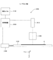
点火装置301は、一例として図2に示されるように、レーザ装置200、射出光学系210、及び保護部材212などを有している。
As shown in FIG. 2 as an example, the
射出光学系210は、レーザ装置200から射出される光を集光する。これにより、集光点で高いエネルギー密度を得ることができる。
The emission
保護部材212は、燃焼室304に臨んで設けられた透明の窓である。ここでは、一例として、保護部材212の材料としてサファイアガラスが用いられている。
The
レーザ装置200は、面発光レーザアレイ201、第1集光光学系203、光ファイバ204、第2集光光学系205、及びレーザ共振器206を備えている。なお、本明細書では、XYZ3次元直交座標系を用い、面発光レーザアレイ201からの光の射出方向を+Z方向として説明する。
The
面発光レーザアレイ201は、励起用光源であり、複数の発光部を有している。各発光部は、垂直共振器型の面発光レーザ(VCSEL:Vertical Cavity Surface Emitting Laser)である。面発光レーザアレイ201から射出される光の波長は808nmである。
The surface emitting
面発光レーザアレイは、射出される光の、温度による波長ずれが非常に少ないため、励起波長のずれによって特性が大きく変化するQスイッチレーザを励起するのに有利な光源である。そこで、面発光レーザアレイを励起用光源に用いると、環境の温度制御を簡易なものにできるという利点がある。 The surface-emitting laser array is a light source that is advantageous for exciting a Q-switched laser whose characteristics change greatly due to a shift in excitation wavelength because the wavelength shift of emitted light due to temperature is very small. Therefore, when a surface emitting laser array is used as an excitation light source, there is an advantage that environmental temperature control can be simplified.
第1集光光学系203は、面発光レーザアレイ201から射出される光を集光する。
The first condensing
光ファイバ204は、第1集光光学系203によって光が集光される位置にコアの−Z側端面の中心が位置するように配置されている。ここでは、光ファイバ204として、コア径が1.5mm、NAが0.39の光ファイバが用いられている。
The
光ファイバ204を設けることによって、面発光レーザアレイ201をレーザ共振器206から離れた位置に置くことができる。これにより配置設計の自由度を増大させることができる。また、レーザ装置200を点火装置に用いる際に、熱源から面発光レーザアレイ201を遠ざけることができるため、エンジン300を冷却する方法の幅を広げることが可能である。
By providing the
光ファイバ204に入射した光はコア内を伝播し、コアの+Z側端面から射出される。
The light incident on the
第2集光光学系205は、光ファイバ204から射出された光の光路上に配置され、該光を集光する。第2集光光学系205で集光された光は、レーザ共振器206に入射する。
The second condensing
レーザ共振器206は、Qスイッチレーザであり、一例として図3に示されるように、レーザ媒質206a、及び可飽和吸収体206bを有している。
The
レーザ媒質206aは、直方体形状のNd:YAG結晶であり、Ndが1.1%ドープされている。可飽和吸収体206bは、直方体形状のCr:YAG結晶であり、初期透過率が0.15(15%)〜0.70(70%)の間で適宜調整されるものである。
The
なお、ここでは、Nd:YAG結晶とCr:YAG結晶は接合されており、いわゆるコンポジット結晶となっている。また、Nd:YAG結晶及びCr:YAG結晶は、いずれもセラミックスである。 Here, the Nd: YAG crystal and the Cr: YAG crystal are joined to form a so-called composite crystal. Both the Nd: YAG crystal and the Cr: YAG crystal are ceramics.
第2集光光学系205からの光は、レーザ媒質206aに入射される。すなわち、第2集光光学系205からの光によってレーザ媒質206aが励起される。なお、面発光レーザアレイ201から射出される光の波長は、YAG結晶において最も吸収効率の高い波長である。そして、可飽和吸収体206bは、Qスイッチの動作を行う。
The light from the second condensing
レーザ媒質206aの入射側(−Z側)の面、及び可飽和吸収体206bの射出側(+Z側)の面は光学研磨処理がなされ、ミラーの役割を果たしている。なお、以下では、便宜上、レーザ媒質206aの入射側の面を「第1の面」ともいい、可飽和吸収体206bの射出側の面を「第2の面」ともいう(図3参照)。
The surface on the incident side (−Z side) of the
そして、第1の面及び第2の面には、面発光レーザアレイ201から射出される光の波長、及びレーザ共振器206から射出される光の波長に応じた誘電体膜がコーティングされている。
The first surface and the second surface are coated with a dielectric film corresponding to the wavelength of light emitted from the surface emitting
具体的には、第1の面には、波長が808nmの光に対して高い透過率を示し、波長が1064nmの光に対して高い反射率を示すコーティングがなされている。また、第2の面には、波長が1064nmの光に対して約50%の反射率を示すコーティングがなされている。 Specifically, the first surface is coated with a high transmittance for light having a wavelength of 808 nm and a high reflectance for light having a wavelength of 1064 nm. The second surface is coated with a reflectance of about 50% for light having a wavelength of 1064 nm.
これにより、レーザ共振器206内で光が共振し増幅される。
As a result, the light resonates and is amplified in the
図2に戻り、駆動装置220は、エンジン制御装置222の指示に基づいて、面発光レーザアレイ201を駆動する。すなわち、駆動装置220は、エンジン300の動作における着火のタイミングで点火装置301から光が射出されるように、面発光レーザアレイ201を駆動する。なお、面発光レーザアレイ201における複数の発光部は、同時に点灯及び消灯される。
Returning to FIG. 2, the driving
上記実施形態において、面発光レーザアレイ201をレーザ共振器206から離れた位置に置く必要がない場合は、光ファイバ204が設けられなくても良い。
In the above embodiment, when it is not necessary to place the surface emitting
また、ここでは、内燃機関として燃焼ガスによってピストンを運動させるエンジン(ピストンエンジン)の場合について説明したが、これに限定されるものではない。例えば、ロータリーエンジンや、ガスタービンエンジンや、ジェットエンジンであっても良い。要するに、燃料を燃焼させて燃焼ガスを生成するものであれば良い。 Here, the case of an engine (piston engine) in which a piston is moved by combustion gas as an internal combustion engine has been described. However, the present invention is not limited to this. For example, a rotary engine, a gas turbine engine, or a jet engine may be used. In short, what is necessary is just to burn the fuel and generate the combustion gas.
また、排熱を利用して、動力や温熱や冷熱を取り出し、総合的にエネルギー効率を高めるシステムであるコジェネレーションに、点火装置301を用いても良い。
In addition, the
また、ここでは、点火装置301が内燃機関に用いられる場合について説明したが、これに限定されるものではない。
Although the case where the
また、ここでは、レーザ装置200が点火装置に用いられる場合について説明したが、これに限定されるものではない。例えば、レーザ加工機、レーザピーニング装置、テラヘルツ発生装置などに用いることができる。
Although the case where the
「詳細」
レーザ装置200から射出される光のZ軸方向に関する集光位置の調整は、射出光学系210の焦点距離、及びZ軸方向に関する射出光学系210の配置位置を調整することにより、行うことができる。
"Details"
The adjustment of the condensing position of the light emitted from the
第1集光光学系203は、少なくとも1つの集光レンズを有している。ここでは、第1集光光学系203における光学素子の構成については限定されない。要するに、面発光レーザアレイ201から射出される光が、光ファイバ204の−Z側端面の中心部に集光されれば良い。
The first condensing
本実施形態では、光ファイバ204を用いることにより、面発光レーザアレイ201とレーザ共振器206との距離を光ファイバ204の長さの分だけ長くすることができる。
In the present embodiment, by using the
そこで、レーザ装置200を内燃機関の点火装置に使用する場合、該内燃機関の周辺の高温領域や振動領域から面発光レーザアレイ201を遠ざけることが可能となり、点火装置の信頼性を向上させることができる。
Therefore, when the
第2集光光学系205は、ここでは、一例として図4に示されるように、第1レンズ205aと第2レンズ205bとから構成されている。
Here, as shown in FIG. 4 as an example, the second condensing
第1レンズ205aは、コリメートレンズであり、光ファイバ204から射出された光を略平行光とする。
The
第2レンズ205bは、集光レンズであり、第1レンズ205aによって略平行光とされた光を集光する。
The
なお、第2集光光学系205は、3つ以上の光学素子から構成されていても良い。また、第2集光光学系205は、1つの光学素子から構成されていても良い。この場合、該1つの光学素子は集光レンズである。
The second condensing
具体的には、レーザ共振器206は、Z軸方向を長手方向とする四角柱形状であり、X軸方向に関する長さ及びY軸方向に関する長さが5mmである。そして、レーザ媒質206aは、Z軸方向に関する長さが5mmであり、屈折率が1.829である。また、可飽和吸収体206bは、初期透過率が0.50(50%)となるように調整されている。
Specifically, the
レーザ共振器206は、本実施形態では、Nd:YAG結晶及びCr:YAG結晶が、いずれもセラミックスであるため、単結晶に比べて生産コストが低く、安価である。また、Nd:YAG結晶とCr:YAG結晶の境界部が分離していないため、単一の結晶と同等の特性が得られ、機械強度的及び光学的に有利である。
In the present embodiment, since the Nd: YAG crystal and the Cr: YAG crystal are both ceramics, the
第2レンズ205bで集光された光は、レーザ媒質206aに入射される。すなわち、第2レンズ205bで集光された光によってレーザ媒質206aが励起される。なお、以下では、レーザ媒質206aに入射される光を「励起光」ともいう。
The light condensed by the
ところで、半導体レーザとして、端面発光レーザが広く知られている。しかしながら、この端面発光レーザから射出される光は、温度に対する波長の変動が大きい。そこで、高温環境下での使用が想定される点火装置では、端面発光レーザを励起用光源に使用する場合、端面発光レーザの温度を一定に保つための精密な温度制御機構が必要になり、点火装置の大型化や高コスト化を招く。 By the way, an edge emitting laser is widely known as a semiconductor laser. However, the light emitted from the edge emitting laser has a large variation in wavelength with respect to temperature. Therefore, in an ignition device that is assumed to be used in a high temperature environment, when an edge emitting laser is used as an excitation light source, a precise temperature control mechanism is required to keep the temperature of the edge emitting laser constant. This increases the size and cost of the device.
一方、面発光レーザアレイから射出される光は、温度に対する波長の変動が端面発光レーザの約1/10である。そこで、面発光レーザアレイを励起用光源に使用する点火装置では、精密な温度制御機構を必要としない。そのため、小型かつ低コストな点火装置を実現することができる。 On the other hand, the light emitted from the surface emitting laser array has a wavelength variation with respect to temperature of about 1/10 that of the edge emitting laser. Therefore, an ignition device that uses a surface emitting laser array as an excitation light source does not require a precise temperature control mechanism. Therefore, a small and low-cost ignition device can be realized.
加えて、面発光レーザアレイは、発光領域が半導体内部にあることから端面破壊の懸念がなく、点火装置の信頼性を向上させることができる。 In addition, since the surface emitting laser array has a light emitting region inside the semiconductor, there is no fear of end face destruction, and the reliability of the ignition device can be improved.
光ファイバ204は、コア径が1.5mm、NAが0.39の光ファイバであり、光ファイバ204から射出される光のビーム品質を示すM2値は約1400である。
The
このとき、ビームウエスト径を直径1mm程度にすると、一例として図5に示されるように、レーザ発振器内で励起光は発散し、発振に寄与しない領域が大きくなる。すなわち、発振効率は悪い。 At this time, when the beam waist diameter is about 1 mm, as shown in FIG. 5 as an example, the excitation light diverges in the laser oscillator, and the region that does not contribute to oscillation becomes large. That is, the oscillation efficiency is poor.
そこで、ビームウエスト径を直径1.5mm程度にすると、一例として図6に示されるように、レーザ発振器内で励起光は発散しにくくなり、発振に寄与しない領域が小さくなる。すなわち、発振効率は向上する。 Therefore, when the beam waist diameter is about 1.5 mm, as shown in FIG. 6 as an example, the excitation light is less likely to diverge in the laser oscillator, and the region that does not contribute to oscillation is reduced. That is, the oscillation efficiency is improved.
本実施形態では、「前記レーザ媒質内での光の体積」に対する「該光におけるビームウエスト径を直径とする円柱部分の体積」の大きさに基づいて、光ファイバから射出される光のM2値と第2集光光学系からの光のビームウエスト径との関係が決定されている。 In this embodiment, M 2 of the light emitted from the optical fiber is based on the “volume of the cylindrical portion having the beam waist diameter in the light as a diameter” with respect to “the volume of the light in the laser medium”. The relationship between the value and the beam waist diameter of the light from the second condensing optical system is determined.
ここでは、光ファイバから射出された光を大気中(屈折率=1.0)で任意のレンズを用いて絞り、該絞られた光のうち、図7に示されるように、Z軸方向に関して、ビームウェスト位置を中心とした5mmの範囲を抽出する。そして、抽出された光の体積をVtとする。また、抽出された光におけるビームウェスト径を直径とする円柱部分の体積をVbとする。そして、次の(1)式で示されるように、Vtに対するVbの大きさを体積比Rv(%)と定義する。
Rv=Vb÷Vt×100 ……(1)
Here, the light emitted from the optical fiber is stopped using an arbitrary lens in the atmosphere (refractive index = 1.0), and, as shown in FIG. Then, a 5 mm range centering on the beam waist position is extracted. And the volume of the extracted light is set to Vt. Further, the volume of the cylindrical portion having the beam waist diameter in the extracted light as a diameter is defined as Vb. Then, as indicated by the following equation (1), the magnitude of Vb with respect to Vt is defined as a volume ratio Rv (%).
Rv = Vb ÷ Vt × 100 (1)
本実施形態では、図8に示されるように、面発光レーザアレイ201における複数の発光部が設けられている領域の直径は、約9mmである。そして、面発光レーザアレイ201から射出される光のパワーは、約300Wである。但し、各光学部材の位置誤差や形状誤差などにより、光ファイバ204から射出される光のパワーは約200Wである。
In the present embodiment, as shown in FIG. 8, the diameter of the region where the plurality of light emitting units is provided in the surface emitting
発明者等は、本実施形態において、体積比Rvが45%以上であれば、エンジン点火に必要なレーザ共振器の出力を得ることができるという新しい知見を得た。このとき、レーザ共振器は、エンジン稼働時を想定し、約100℃に加熱した際に、500μ秒中に、2.5mJのパルス光を4パルス出力することができた。なお、2.5mJのパルス光を4パルス出力できれば、エンジンを安定して稼働させることが可能である(常包正樹、他5名、「マイクロレーザーによるエンジン点火」、レーザー研究、第37巻第4号、p283−p289、2009年4月、参照)。 The inventors obtained new knowledge that, in this embodiment, if the volume ratio Rv is 45% or more, the output of the laser resonator necessary for engine ignition can be obtained. At this time, the laser resonator was able to output four pulses of 2.5 mJ pulsed light within 500 μsec when heated to about 100 ° C., assuming that the engine was in operation. If 4 pulses of 2.5 mJ pulsed light can be output, it is possible to operate the engine stably (Masaki Tokibu, five others, “Engine Ignition with Microlasers”, Laser Research, Vol. 37, Vol. 4, p283-p289, April 2009).
図9には、体積比Rvが45%のときの、光ファイバ204から射出される光のM2値と第2集光光学系205からの光のビームウェスト径(直径)Dとの関係が示されている。この関係は、次の(2)式で示されることが判明した。
M2値=769.1×D2−53.166×D ……(2)
FIG. 9 shows the relationship between the M 2 value of the light emitted from the
M 2 value = 769.1 × D 2 −53.166 × D (2)
そして、次の(3)式が満足されると、体積比Rvは45%以上となる。
M2値≦769.1×D2−53.166×D ……(3)
When the following expression (3) is satisfied, the volume ratio Rv is 45% or more.
M 2 value ≦ 769.1 × D 2 −53.166 × D (3)
すなわち、上記(3)式が満足されると、エンジン点火に必要なレーザ共振器の出力を得ることができる。本実施形態では、M2値が1400であるため、次の(4)式が満足されるように設定されている。
769.1×D2−53.166×D≧1400 ……(4)
That is, when the above expression (3) is satisfied, the output of the laser resonator necessary for engine ignition can be obtained. In the present embodiment, since M 2 value of 1400 is set as follows: (4) is satisfied.
769.1 × D 2 −53.166 × D ≧ 1400 (4)
上記(4)式を解くと、D≧1.385mmとなる。本実施形態では、ビームウェスト径Dが1.60mm(1/e2)となるように設定されている。 When the above equation (4) is solved, D ≧ 1.385 mm. In this embodiment, the beam waist diameter D is set to 1.60 mm (1 / e 2 ).
ところで、一例として図10に示されるように、レーザ媒質206aに入射した光がレーザ媒質206a内を通過する際に、レーザ媒質206aの側面に当たると、レーザ媒質206a内に励起光が戻り、レーザ媒質206a内で熱が発生し、レーザ媒質206aの特性に悪影響を与えるおそれがある。また、場合によっては、レーザ媒質206aの側面で反射された励起光がレーザ媒質206a内で増幅され、望まない寄生発振が生じるおそれがある。この寄生発振は不要な発振であり、本来の光の増幅に使われるべき励起エネルギーを消費してしまうため、レーザ共振器の出力低下をもたらす。
As an example, as shown in FIG. 10, when light incident on the
そこで、本実施形態では、レーザ媒質206aに入射した光がレーザ媒質206a内を通過する際に、レーザ媒質206aの側面に当たらないように設定されている(図11参照)。
Therefore, in the present embodiment, it is set so that the light incident on the
また、一例として図12に示されるように、レーザ媒質206aの入射端面(第1の面)よりも、励起光のビーム径のほうが大きいと、励起光の一部はレーザ媒質206aの側面に当たり、励起光がそこで反射される。この場合、励起光のエネルギーがQスイッチレーザに変換されず、発振効率が低下する。
As an example, as shown in FIG. 12, when the beam diameter of the excitation light is larger than the incident end face (first surface) of the
そこで、本実施形態では、レーザ媒質206aの入射端面(第1の面)の大きさが、励起光のビーム径よりも大きくなるように設定されている(図13参照)。
Therefore, in the present embodiment, the size of the incident end surface (first surface) of the
以上の説明から明らかなように、本実施形態に係るレーザ装置200では、面発光レーザアレイ201と第1集光光学系203とによって、本発明のレーザ装置における光源装置が構成されている。また、本実施形態に係るレーザ装置200では、第2集光光学系205によって、本発明のレーザ装置における光学系が構成され、光ファイバ204によって、本発明のレーザ装置における伝送部材が構成されている。
As is apparent from the above description, in the
そして、本実施形態に係る点火装置301では、射出光学系210によって、本発明の点火装置における「レーザ装置からの光を集光する光学系」が構成されている。
In the
以上説明したように、本実施形態に係るレーザ装置200は、面発光レーザアレイ201、第1集光光学系203、光ファイバ204、第2集光光学系205、及びレーザ共振器206などを備えている。
As described above, the
面発光レーザアレイ201は、励起用光源であり、面発光レーザアレイ201から射出された光は、第1集光光学系203、光ファイバ204、及び第2集光光学系205を介して、励起光としてレーザ共振器206に入射される。
The surface emitting
レーザ共振器206は、Qスイッチレーザであり、レーザ媒質206a、及び可飽和吸収体206bを有している。
The
そして、体積比Rvに基づいて、光ファイバ204から射出される光のM2値と第2集光光学系205からの光のビームウエスト径との関係が決定されている。すなわち、レーザ媒質206aのZ軸方向に関する長さは5mmであり、「レーザ媒質206a内での光の体積」に対する「該光におけるビームウエスト径を直径とする円柱部分の体積」の大きさに対応する体積比Rvは45%以上であり、光ファイバ204から射出される光のM2値と第2集光光学系205からの光のビームウェスト径Dとの関係が上記(3)式を満足するように設定されている。また、レーザ媒質206a内を通過する光がレーザ媒質206aの側面に当たらないように設定されている。さらに、レーザ媒質206aの入射端面(第1の面)の大きさが、励起光のビーム径よりも大きくなるように設定されている。この場合は、発振効率を向上させることができる。
Based on the volume ratio Rv, the relationship between the M 2 value of the light emitted from the
そして、点火装置301は、レーザ装置200を備えているため、安定した点火を効率良く行うことができる。
Since the
また、エンジン300は、点火装置301を備えているため、結果として、効率化を図ることができる。
Further, since
なお、上記実施形態において、射出光学系210は、単一の光学素子からなっていても良いし、複数の光学素子からなっていても良い。
In the above embodiment, the emission
また、上記実施形態において、励起用光源として面発光レーザアレイが用いられる場合について説明したが、これに限定されるものではない。 Moreover, in the said embodiment, although the case where a surface emitting laser array was used as a light source for excitation was demonstrated, it is not limited to this.
また、上記実施形態では、光ファイバ204から射出される光のパワーが200Wの場合について説明したが、これに限定されるものではない。なお、光ファイバ204から射出される光のパワーは200W以上が好ましい。
Moreover, although the said embodiment demonstrated the case where the power of the light inject | emitted from the
また、上記実施形態では、光ファイバ204から射出される光のM2値が1400の場合について説明したが、これに限定されるものではない。光ファイバ204から射出される光のM2値に応じて第2集光光学系205からの光のビームウェスト径を決定することにより、上記実施形態と同様な効果を得ることができる。
Further, in the above embodiment, the M 2 value of the light emitted from the
また、上記実施形態では、レーザ媒質206aのZ軸方向に関する長さが5mmの場合について説明したが、これに限定されるものではない。なお、レーザ媒質206aのZ軸方向に関する長さがあまり小さいと、レーザ共振器206から射出されるレーザ光の品質が低下する。そこで、レーザ媒質206aのZ軸方向に関する長さは5mm以上が好ましい。
Moreover, although the said embodiment demonstrated the case where the length regarding the Z-axis direction of the
また、レーザ装置200は、レーザアニール装置やレーザ加工機に用いることができる。
The
《レーザアニール装置》
一例として図14(A)及び図14(B)に、レーザ装置200を有するレーザアニール装置1000の概略構成が示されている。このレーザアニール装置1000は、光源1010、光学系1020、テーブル装置1030、及び制御装置などを備えている。
<Laser annealing equipment>
As an example, FIG. 14A and FIG. 14B show a schematic configuration of a
光源1010は、前述したレーザ装置200を有し、レーザ光を射出することができる。光学系1020は、光源1010から射出されたレーザ光を対象物Pの表面に導光する。テーブル装置1030は、対象物Pが載置されるテーブルを有している。該テーブルは、少なくともY軸方向に沿って移動することができる。
The
例えば、対象物Pがアモルファスシリコン(a−Si)の場合、レーザ光が照射されると、アモルファスシリコン(a−Si)は、温度が上昇し、その後、徐々に冷却されることによって結晶化し、ポリシリコン(p−Si)になる。 For example, in the case where the object P is amorphous silicon (a-Si), when irradiated with laser light, the amorphous silicon (a-Si) is crystallized by increasing the temperature and then gradually cooling, It becomes polysilicon (p-Si).
このレーザアニール装置1000は、光源1010がレーザ装置200を有しているため、処理効率を向上させることができる。
In this
《レーザ加工機》
一例として図15に、前述したレーザ装置200を有するレーザ加工機3000の概略構成が示されている。このレーザ加工機3000は、光源3010、光学系3100、対象物Pが載置されるテーブル3150、テーブル駆動装置3160、操作パネル3180及び制御装置3200などを備えている。
<Laser processing machine>
As an example, FIG. 15 shows a schematic configuration of a
光源3010は、レーザ装置200を有し、制御装置3200の指示に基づいてレーザ光を射出する。光学系3100は、光源3010から射出されたレーザ光を対象物Pの表面近傍で集光させる。テーブル駆動装置3160は、制御装置3200の指示に基づいて、テーブル3150をX軸方向、Y軸方向、及びZ軸方向に移動させる。
The
操作パネル3180は、作業者が各種設定を行うための複数のキー、及び各種情報を表示するための表示器を有している。制御装置3200は、操作パネル3180からの各種設定情報に基づいて、光源3010及びテーブル駆動装置3160を制御する。
The
このレーザ加工機3000は、光源3010がレーザ装置200を有しているため、加工(例えば、切断や溶接)の処理効率を向上させることができる。
In the
なお、レーザ加工機3000は、複数の光源3010を有しても良い。
Note that the
また、前述したレーザ装置200は、レーザアニール装置及びレーザ加工機以外のレーザ光を利用する装置にも好適である。例えば、レーザ装置200を表示装置の光源に用いても良い。
Further, the
200…レーザ装置、201…面発光レーザアレイ(光源装置の一部)、203…第1集光光学系(光源装置の一部)、204…光ファイバ(伝送部材)、205…第2集光光学系(光伝送部材からの光を集光する光学系)、205a…第1レンズ、205b…第2レンズ、206…レーザ共振器、206a…レーザ媒質、206b…可飽和吸収体、210…射出光学系(レーザ装置からの光を集光する光学系)、212…保護部材、220…駆動装置、222…エンジン制御装置、300…エンジン(内燃機関)、301…点火装置、302…燃料噴出機構、303…排気機構、304…燃焼室、305…ピストン、1000…レーザアニール装置、1010…光源、1020…光学系、1030…テーブル装置、3000…レーザ加工機、3010…光源、3100…光学系、3150…テーブル、3160…テーブル駆動装置、3180…操作パネル、3200…制御装置、P…対象物。
DESCRIPTION OF
Claims (15)
前記光源装置からの光を伝送する光伝送部材と、
前記光伝送部材からの光を集光する光学系と、
レーザ媒質を含み、前記光学系からの光によって励起されるレーザ共振器とを備え、
「前記レーザ媒質内での光の体積」に対する「該光におけるビームウエスト径を直径とする円柱部分の体積」の大きさに基づいて、前記光伝送部材から射出される光のM2値と前記光学系からの光のビームウエスト径との関係が決定されているレーザ装置。 A light source device;
An optical transmission member for transmitting light from the light source device;
An optical system for collecting light from the light transmission member;
A laser resonator including a laser medium and excited by light from the optical system,
Based on the size of “the volume of the cylindrical portion whose diameter is the beam waist diameter in the light” relative to “the volume of light in the laser medium”, the M 2 value of the light emitted from the optical transmission member and the A laser apparatus in which a relationship with a beam waist diameter of light from an optical system is determined.
前記光学系からの光について、大気中において、該光の進行方向に関して、ビームウェスト位置を中心として前記レーザ媒質の長さに対応した範囲を抽出し、該抽出された光の体積をVt、該抽出された光におけるビームウェスト径を直径とする円柱部分の体積をVbとしたとき、Vb÷Vt×100で得られる体積比(%)に基づいて、決定されていることを特徴とする請求項1に記載のレーザ装置。 The relationship between the M 2 value of light emitted from the light transmission member and the beam waist diameter of light from the optical system is as follows:
For the light from the optical system, in the atmosphere, the range corresponding to the length of the laser medium is extracted with the beam waist position as the center with respect to the traveling direction of the light, the volume of the extracted light is Vt, The volume is determined based on a volume ratio (%) obtained by Vb ÷ Vt × 100, where Vb is a volume of a cylindrical portion having a beam waist diameter in the extracted light as a diameter. 2. The laser device according to 1.
前記レーザ装置からの光を集光する光学系とを備える点火装置。 A laser device according to any one of claims 1 to 13,
And an optical system that collects light from the laser device.
前記燃料に点火するための請求項14に記載の点火装置を備える内燃機関。 In an internal combustion engine that generates combustion gas by burning fuel,
An internal combustion engine comprising the ignition device according to claim 14 for igniting the fuel.
Priority Applications (1)
| Application Number | Priority Date | Filing Date | Title |
|---|---|---|---|
| JP2016228544A JP2018085469A (en) | 2016-11-25 | 2016-11-25 | Laser device, ignition device and internal combustion engine |
Applications Claiming Priority (1)
| Application Number | Priority Date | Filing Date | Title |
|---|---|---|---|
| JP2016228544A JP2018085469A (en) | 2016-11-25 | 2016-11-25 | Laser device, ignition device and internal combustion engine |
Publications (2)
| Publication Number | Publication Date |
|---|---|
| JP2018085469A true JP2018085469A (en) | 2018-05-31 |
| JP2018085469A5 JP2018085469A5 (en) | 2019-11-14 |
Family
ID=62237671
Family Applications (1)
| Application Number | Title | Priority Date | Filing Date |
|---|---|---|---|
| JP2016228544A Pending JP2018085469A (en) | 2016-11-25 | 2016-11-25 | Laser device, ignition device and internal combustion engine |
Country Status (1)
| Country | Link |
|---|---|
| JP (1) | JP2018085469A (en) |
Cited By (1)
| Publication number | Priority date | Publication date | Assignee | Title |
|---|---|---|---|---|
| WO2020166420A1 (en) * | 2019-02-13 | 2020-08-20 | ソニー株式会社 | Laser processing machine, processing method, and laser light source |
Citations (1)
| Publication number | Priority date | Publication date | Assignee | Title |
|---|---|---|---|---|
| JP2016072617A (en) * | 2014-09-30 | 2016-05-09 | 株式会社リコー | Laser apparatus, ignition apparatus and internal combustion engine |
-
2016
- 2016-11-25 JP JP2016228544A patent/JP2018085469A/en active Pending
Patent Citations (1)
| Publication number | Priority date | Publication date | Assignee | Title |
|---|---|---|---|---|
| JP2016072617A (en) * | 2014-09-30 | 2016-05-09 | 株式会社リコー | Laser apparatus, ignition apparatus and internal combustion engine |
Cited By (4)
| Publication number | Priority date | Publication date | Assignee | Title |
|---|---|---|---|---|
| WO2020166420A1 (en) * | 2019-02-13 | 2020-08-20 | ソニー株式会社 | Laser processing machine, processing method, and laser light source |
| CN113423529A (en) * | 2019-02-13 | 2021-09-21 | 索尼集团公司 | Laser processing machine, processing method and laser light source |
| JPWO2020166420A1 (en) * | 2019-02-13 | 2021-12-09 | ソニーグループ株式会社 | Laser processing machine, processing method and laser light source |
| JP7380602B2 (en) | 2019-02-13 | 2023-11-15 | ソニーグループ株式会社 | Laser processing machine and laser processing method |
Similar Documents
| Publication | Publication Date | Title |
|---|---|---|
| US9935420B2 (en) | Laser device, ignition system, and internal combustion engine | |
| JP2020127051A (en) | Laser device, ignition device, and internal combustion engine | |
| CN101989048B (en) | Light source device | |
| JP6741207B2 (en) | Laser device, ignition device and internal combustion engine | |
| JP5203573B2 (en) | Laser processing equipment | |
| EP3002835A1 (en) | Laser device, ignition system, and internal combustion engine | |
| JP2012087774A (en) | Laser ignition device | |
| CN102189343A (en) | Laser processing device, laser source device and controlling method thereof | |
| JP6848302B2 (en) | Surface emitting laser array and laser equipment | |
| JP6358531B2 (en) | Laser ignition device | |
| JP2016072610A (en) | Laser apparatus, ignition apparatus and internal combustion engine | |
| JP6739748B2 (en) | Laser device, ignition device and internal combustion engine | |
| JP2010014030A (en) | Laser ignition device | |
| EP3023631A1 (en) | Laser device, ignition system, and internal combustion engine | |
| JP2017111278A (en) | Optical window member, laser device, ignition device, and internal combustion engine | |
| JP2018085469A (en) | Laser device, ignition device and internal combustion engine | |
| JP2017106406A (en) | Laser ignition device and internal combustion engine | |
| JP2018074105A (en) | Laser device, ignition device and internal combustion engine | |
| JP2018184849A (en) | Laser ignition device | |
| JP2016072611A (en) | Laser apparatus, ignition apparatus and internal combustion engine | |
| WO2020196579A1 (en) | Laser ignition device, space engine, and aircraft engine | |
| Wintner et al. | Laser plasma ignition: status, perspectives, solutions | |
| JP6848337B2 (en) | Laser device, ignition device, and internal combustion engine | |
| JP7040033B2 (en) | Laser device and internal combustion engine | |
| Wintner | The Evolution of Laser Ignition |
Legal Events
| Date | Code | Title | Description |
|---|---|---|---|
| A521 | Request for written amendment filed |
Free format text: JAPANESE INTERMEDIATE CODE: A523 Effective date: 20191001 |
|
| A621 | Written request for application examination |
Free format text: JAPANESE INTERMEDIATE CODE: A621 Effective date: 20191001 |
|
| RD04 | Notification of resignation of power of attorney |
Free format text: JAPANESE INTERMEDIATE CODE: A7424 Effective date: 20200701 |
|
| A977 | Report on retrieval |
Free format text: JAPANESE INTERMEDIATE CODE: A971007 Effective date: 20200819 |
|
| A131 | Notification of reasons for refusal |
Free format text: JAPANESE INTERMEDIATE CODE: A131 Effective date: 20200915 |
|
| A521 | Request for written amendment filed |
Free format text: JAPANESE INTERMEDIATE CODE: A523 Effective date: 20201110 |
|
| A02 | Decision of refusal |
Free format text: JAPANESE INTERMEDIATE CODE: A02 Effective date: 20210413 |