JP2018057797A - Game machine - Google Patents

Game machine Download PDF

Info

Publication number
JP2018057797A
JP2018057797A JP2016233201A JP2016233201A JP2018057797A JP 2018057797 A JP2018057797 A JP 2018057797A JP 2016233201 A JP2016233201 A JP 2016233201A JP 2016233201 A JP2016233201 A JP 2016233201A JP 2018057797 A JP2018057797 A JP 2018057797A
Authority
JP
Japan
Prior art keywords
unit
game ball
path
view
opening
Prior art date
Legal status (The legal status is an assumption and is not a legal conclusion. Google has not performed a legal analysis and makes no representation as to the accuracy of the status listed.)
Pending
Application number
JP2016233201A
Other languages
Japanese (ja)
Inventor
勝貴 早川
Katsutaka Hayakawa
勝貴 早川
Current Assignee (The listed assignees may be inaccurate. Google has not performed a legal analysis and makes no representation or warranty as to the accuracy of the list.)
Sanyo Bussan Co Ltd
Original Assignee
Sanyo Bussan Co Ltd
Priority date (The priority date is an assumption and is not a legal conclusion. Google has not performed a legal analysis and makes no representation as to the accuracy of the date listed.)
Filing date
Publication date
Application filed by Sanyo Bussan Co Ltd filed Critical Sanyo Bussan Co Ltd
Publication of JP2018057797A publication Critical patent/JP2018057797A/en
Priority to JP2020145177A priority Critical patent/JP6939967B2/en
Pending legal-status Critical Current

Links

Images

Abstract

PROBLEM TO BE SOLVED: To provide a game machine enabling a player to recognize positions of game balls received by a reception part.SOLUTION: A lower displacement member 11440 is formed from a light transmissive material at a front side, and is formed while including a transmission part 11451a formed so as to have an external form larger than a displacement area of a ball reception part 467c in front view. A light emitting body 11491a, which is arranged at a rear side of the ball reception part 467c and emits light to a player side, is arranged at height overlapping with the ball reception part 467c in a longitudinal direction. Accordingly, by blocking off the light emitted from the light emitting body 11491a by game balls arranged in the ball reception part 467c, a shadow blocked off by the game balls can be displayed in the transmission part 11451a. As a result, the player is allowed to recognize positions of the game balls received by the reception part (ball reception part 467c).SELECTED DRAWING: Figure 153

Description

本発明は、パチンコ機などの遊技機に関するものである。   The present invention relates to a gaming machine such as a pachinko machine.

パチンコ機等の遊技機において、前面に装飾が施される装飾部材と、その装飾部材の背面を変位可能な状態で配設されると共に、遊技球を受け入れて保持できる受入部と、を備え、受入部の移動に伴って遊技球を移動させる演出を行う遊技機が知られている(特許文献1)。   In a gaming machine such as a pachinko machine, provided with a decorative member that is decorated on the front surface, a receiving portion that is disposed in a displaceable manner on the back surface of the decorative member, and can receive and hold a game ball A gaming machine that produces an effect of moving a game ball in accordance with the movement of a receiving unit is known (Patent Document 1).

特開2010−166997号公報JP 2010-166997 A

しかしながら、上述した遊技機では、受入部に受け入れられた(保持された)遊技球の位置が分からなくなるという問題点があった。   However, the above-described gaming machine has a problem that the position of the gaming ball received (held) by the receiving unit cannot be known.

本発明は、上記例示した問題点を解決するためになされたものであり、受入部に受け入れられた(保持された)遊技球の位置を遊技者に認識させることができる遊技機を提供することを目的とする。   The present invention has been made to solve the above-described problems, and provides a gaming machine that allows a player to recognize the position of a game ball received (held) by a receiving unit. With the goal.

この目的を達成するために請求項1記載の遊技機は、正面視において少なくとも一部が背面側の光を透過可能な光透過性材料から形成される装飾部材と、その装飾部材の背面側に正面と平行な平面上を変位可能な状態で配設され、遊技球を受け入れて保持可能な受入部と、を備えるものであり、前記装飾部材の背面側に配設され、前記受入部の変位領域に向けて光を出射可能な発光手段を備え、前記発光手段は、前記受入部の背面側、又は、前記装飾部材と前記受入部との間に配設され、前記受入部または受入部に受け入れられた遊技球により、前記発光手段から出射される光を遮断または反射して、前記装飾部材から出射される光の光量を部分的に異ならせる。   In order to achieve this object, the gaming machine according to claim 1 is provided with a decorative member formed of a light-transmitting material capable of transmitting light on the back side when viewed from the front, and on the back side of the decorative member. A receiving portion that is disposed in a displaceable manner on a plane parallel to the front surface and that can receive and hold a game ball, and is disposed on the back side of the decorative member, and the displacement of the receiving portion A light emitting means capable of emitting light toward the region, wherein the light emitting means is disposed on the back side of the receiving portion or between the decorative member and the receiving portion, and is disposed on the receiving portion or the receiving portion. The light emitted from the light emitting means is blocked or reflected by the received game ball, and the amount of light emitted from the decorative member is partially varied.

請求項2記載の遊技機は、請求項1記載の遊技機において、前記受入部は、その受入部に保持される遊技球の中心よりも重力方向下側に形成され、前記発光手段は、前記受入部に保持される遊技球の中心と略同一の高さに光の出射部分が配置され、前記装飾部材の光透過部分が、前記発光手段の光の出射部分よりも高い位置に形成される。   The gaming machine according to claim 2 is the gaming machine according to claim 1, wherein the receiving portion is formed below the center of the game ball held in the receiving portion in the gravity direction, and the light emitting means A light emitting portion is arranged at substantially the same height as the center of the game ball held in the receiving portion, and the light transmitting portion of the decorative member is formed at a position higher than the light emitting portion of the light emitting means. .

請求項3記載の遊技機は、請求項1又は2に記載の遊技機において、前記受入部は、光透過性材料から形成される。   A gaming machine according to a third aspect is the gaming machine according to the first or second aspect, wherein the receiving portion is formed of a light transmissive material.

請求項1記載の遊技機によれば、受入部に受け入れられた(保持された)遊技球の位置を遊技者に認識させることができる。   According to the gaming machine of the first aspect, the player can recognize the position of the game ball received (held) by the receiving unit.

請求項2記載の遊技機によれば、請求項1記載の遊技機の奏する効果に加え、遊技球により透過部の正面側に光の明暗を形成しやすくできる。   According to the gaming machine of the second aspect, in addition to the effect produced by the gaming machine of the first aspect, the light and darkness of the light can be easily formed on the front side of the transmission part by the game ball.

請求項3記載の遊技機によれば、請求項1又は2に記載の遊技機の奏する効果に加え、受入部に遊技球が保持された場合にのみ遊技者に注視させることができる。   According to the gaming machine of the third aspect, in addition to the effect produced by the gaming machine according to the first or second aspect, the player can be watched only when the game ball is held in the receiving unit.

第1実施形態におけるパチンコ機の正面図である。It is a front view of the pachinko machine in a 1st embodiment. パチンコ機の遊技盤の正面図である。It is a front view of the game board of a pachinko machine. パチンコ機の背面図である。It is a rear view of a pachinko machine. パチンコ機の電気的構成を示すブロック図である。It is a block diagram which shows the electric constitution of a pachinko machine. パチンコ機の分解斜視正面図である。It is a disassembled perspective front view of a pachinko machine. 動作ユニットおよび遊技盤の分解斜視正面図である。It is a disassembled perspective front view of an operation unit and a game board. 動作ユニットの正面図である。It is a front view of an operation unit. 動作ユニットの正面図である。It is a front view of an operation unit. 動作ユニットの正面図である。It is a front view of an operation unit. 動作ユニットの正面図である。It is a front view of an operation unit. 遊技盤の分解斜視正面図である。It is a disassembled perspective front view of a game board. (a)は、一般入賞口ユニットの正面図であり、(b)は、図12(a)のXIIb−XIIb線における一般入賞口ユニットの断面図である。(A) is a front view of a general winning opening unit, and (b) is a cross-sectional view of the general winning opening unit along line XIIb-XIIb in FIG. 12 (a). 図2のXIII−XIII線における遊技盤の断面図である。It is sectional drawing of the game board in the XIII-XIII line | wire of FIG. 図13の範囲XIVにおける遊技盤の部分拡大断面図である。It is a partial expanded sectional view of the game board in the range XIV of FIG. 一般入賞口ユニットの背面図である。It is a rear view of a general winning opening unit. 図13の範囲XIVにおける遊技盤の部分拡大断面図である。It is a partial expanded sectional view of the game board in the range XIV of FIG. センターフレームの分解斜視正面図である。It is a disassembled perspective front view of a center frame. (a)は、第1ユニットの正面図であり、(b)は、第1ユニットの側面図であり、(c)は、第1ユニットの背面図である。(A) is a front view of the first unit, (b) is a side view of the first unit, and (c) is a rear view of the first unit. 第1ユニットの分解斜視正面図である。It is a disassembled perspective front view of a 1st unit. 第1ユニットの分解斜視背面図である。It is a disassembled perspective rear view of a 1st unit. 図18(b)のXXI−XXI線における第1ユニットの断面図である。It is sectional drawing of the 1st unit in the XXI-XXI line | wire of FIG.18 (b). 図21に示す第1ユニットの模式断面図である。It is a schematic cross section of the 1st unit shown in FIG. 図18(b)のXXIII−XXIII線における第1ユニットの断面図である。It is sectional drawing of the 1st unit in the XXIII-XXIII line | wire of FIG.18 (b). (a)は、図21のXXIVa−XXIVa線における第1ユニットの断面図であり、(b)は、図21のXXIVb−XXIVb線における第1ユニットの断面図であり、(c)は、図21のXXIVc−XXIVc線における第1ユニットの断面図である。(A) is sectional drawing of the 1st unit in the XXIVa-XXIVa line of FIG. 21, (b) is sectional drawing of the 1st unit in the XXIVb-XXIVb line of FIG. 21, (c) is a figure. It is sectional drawing of the 1st unit in the XXIVc-XXIVc line of 21. (a)は、図21の範囲XXVaにおける第1ユニットの部分拡大図であり、(b)は、図25(a)のXXIVb−XXIVb線における第1ユニットの断面図である。(A) is the elements on larger scale of the 1st unit in the range XXVa of FIG. 21, (b) is sectional drawing of the 1st unit in the XXIVb-XXIVb line | wire of FIG. 25 (a). (a)は、図21の範囲XXVaにおける第1ユニットの部分拡大図であり、(b)は、図26(a)のXXIVb−XXIVb線における第1ユニットの断面図である。(A) is the elements on larger scale of the 1st unit in the range XXVa of FIG. 21, (b) is sectional drawing of the 1st unit in the XXIVb-XXIVb line | wire of Fig.26 (a). (a)は、図25(a)のXXVIIa−XXVIIa線における第1ユニットの模式断面図であり、(b)は、図25(a)のXXVIIb−XXVIIb線における第1ユニットの模式断面図であり、(c)は、図25(a)のXXVIIc−XXVIIc線における第1ユニットの模式断面図である。(A) is a schematic cross-sectional view of the first unit along the line XXVIIa-XXVIIa of FIG. 25 (a), and (b) is a schematic cross-sectional view of the first unit along the line XXVIIb-XXVIIb of FIG. 25 (a). FIG. 26C is a schematic cross-sectional view of the first unit taken along line XXVIIc-XXVIIc in FIG. (a)は、図25(a)のXXVb−XXVb線における第1ユニットの模式断面図であり、(b)は、図25(a)のXXVIIIb−XXVIIIb線における第1ユニットの模式断面図である。(A) is a schematic cross-sectional view of the first unit along the line XXVb-XXVb of FIG. 25 (a), and (b) is a schematic cross-sectional view of the first unit along the line XXVIIIb-XXVIIIb of FIG. 25 (a). is there. (a)は、第2ユニットの正面図であり、(b)は、第2ユニットの背面図である。(A) is a front view of a 2nd unit, (b) is a rear view of a 2nd unit. 第2ユニットの分解斜視正面図である。It is a disassembled perspective front view of a 2nd unit. 第2ユニットの分解斜視背面図である。It is a disassembled perspective rear view of a 2nd unit. 図29のXXXII−XXXII線における第2ユニットの断面図である。It is sectional drawing of the 2nd unit in the XXXII-XXXII line | wire of FIG. (a)は、センターフレームの正面図であり、(b)は、センターフレームの側面図である。(A) is a front view of a center frame, (b) is a side view of a center frame. (a)は、センターフレームの斜視正面図であり、(b)は、センターフレームの斜視背面図である。(A) is a perspective front view of a center frame, (b) is a perspective rear view of a center frame. センターフレームの分解斜視背面図である。It is a disassembled perspective rear view of a center frame. 図33のXXXVI−XXXVI線におけるセンターフレームの断面図である。It is sectional drawing of the center frame in the XXXVI-XXXVI line of FIG. (a)は、遊技盤の模式断面図であり、(b)は、遊技盤の模式分解断面図である。(A) is a schematic cross-sectional view of the game board, (b) is a schematic exploded cross-sectional view of the game board. (a)は、背面ケースの正面図であり、(b)は、背面ケースの背面図である。(A) is a front view of a back case, (b) is a rear view of a back case. (a)は、背面ケースの分解斜視正面図であり、(b)は、背面ケースの分解斜視背面図である。(A) is an exploded perspective front view of a back case, (b) is an exploded perspective rear view of a back case. (a)は、背面ケースの正面図であり、(b)は、背面ケースの背面図である。(A) is a front view of a back case, (b) is a rear view of a back case. (a)は、背面ケースの正面図であり、(b)は、背面ケースの背面図である。(A) is a front view of a back case, (b) is a rear view of a back case. (a)は、背面ケースおよび基板ボックスの斜視背面図であり、(b)は、背面ケースおよび基板ボックスの背面図である。(A) is a perspective rear view of a back case and a board | substrate box, (b) is a rear view of a back case and a board | substrate box. 下変位ユニットの正面図である。It is a front view of a lower displacement unit. 下変位ユニットの背面図である。It is a rear view of a lower displacement unit. 下変位ユニットの分解斜視正面図である。It is a disassembled perspective front view of a lower displacement unit. 下変位ユニットの分解斜視背面図である。It is a disassembled perspective rear view of a lower displacement unit. 退避状態における下変位ユニットの正面図である。It is a front view of the lower displacement unit in a retracted state. 第1張出状態における下変位ユニットの正面図である。It is a front view of the lower displacement unit in the 1st overhanging state. 第2張出状態における下変位ユニットの正面図である。It is a front view of the lower displacement unit in the 2nd overhanging state. 退避状態における下変位ユニットの背面図である。It is a rear view of the lower displacement unit in the retracted state. 第1張出状態における下変位ユニットの背面図である。It is a rear view of the lower displacement unit in the 1st overhanging state. 第2張出状態における下変位ユニットの背面図である。It is a rear view of the lower displacement unit in the 2nd overhanging state. (a)は退避状態における、(b)は第1張出状態における、(c)は第2張出状態における、第1リンク部材とカム部材との背面図である。(A) is a back view of the first link member and the cam member in the retracted state, (b) in the first extended state, and (c) in the second extended state. 図50のLIVa−LIVa線における下変位ユニットの断面模式図であり、(b)は、図51のLIVb−LIVb線における下変位ユニットの断面模式図である。It is a cross-sectional schematic diagram of the lower displacement unit along the LIVa-LIVa line of FIG. 50, and (b) is a schematic cross-sectional view of the lower displacement unit along the LIVb-LIVb line of FIG. (a)は、図50のLVa−LVa線における下変位ユニットの断面図であり、(b)は、図51のLVb−LVb線における下変位ユニットの断面図であり、(c)は、図52のLVc−LVc線における下変位ユニットの断面図である。(A) is sectional drawing of the lower displacement unit in the LVa-LVa line of FIG. 50, (b) is sectional drawing of the lower displacement unit in the LVb-LVb line of FIG. 51, (c) is a figure. It is sectional drawing of the lower displacement unit in the LVc-LVc line | wire of 52. (a)は、図52のLVIa−LVIa線における下変位ユニットの断面図であり、(b)は、第2張出状態における下変位ユニットの第1リンク部材およびカム部材の正面図である。(A) is sectional drawing of the lower displacement unit in the LVIa-LVIa line | wire of FIG. 52, (b) is a front view of the 1st link member and cam member of the lower displacement unit in a 2nd overhang | projection state. (a)は、下変位部材の正面図であり、(b)は、下変位部材の背面図である。(A) is a front view of a lower displacement member, (b) is a rear view of a lower displacement member. 下変位部材の分解斜視正面図である。It is a disassembled perspective front view of a lower displacement member. 下変位部材の分解斜視背面図である。It is a disassembled perspective rear view of a lower displacement member. (a)及び(b)は、下変位部材の正面図である。(A) And (b) is a front view of a lower displacement member. 第1位置における下変位部材の正面図である。It is a front view of the lower displacement member in the 1st position. 第2位置における下変位部材の正面図である。It is a front view of the lower displacement member in the 2nd position. 第3位置における下変位部材の正面図である。It is a front view of the lower displacement member in the 3rd position. (a)から(c)は、下変位部材の部分拡大図である。(A)-(c) is the elements on larger scale of a lower displacement member. (a)から(c)は、下変位部材の正面図である。(A) to (c) is a front view of the lower displacement member. (a)から(c)は、下変位部材の正面図である。(A) to (c) is a front view of the lower displacement member. (a)から(c)は、下変位部材の正面図である。(A) to (c) is a front view of the lower displacement member. (a)から(c)は、下変位部材の正面図である。(A) to (c) is a front view of the lower displacement member. (a)は、図68(b)の範囲LXIXaにおける下変位部材の部分拡大図であり、(b)は、図68(a)の範囲LXIXbにおける下変位部材の部分拡大図である。(A) is the elements on larger scale of the lower displacement member in the range LXIXa of FIG.68 (b), (b) is the elements on larger scale of the lower displacement member in the range LXIXb of FIG.68 (a). (a)は、振分けユニットの上面図であり、(b)は、振分けユニットの背面図である。(A) is a top view of a distribution unit, (b) is a rear view of a distribution unit. 振分けユニットの分解正面斜視図である。It is a disassembled front perspective view of a distribution unit. 振分けユニットの分解背面斜視図である。It is a disassembled back perspective view of a distribution unit. 図70(a)のLXXIII−LXXIII線における振分けユニットの断面図である。It is sectional drawing of the distribution unit in the LXXIII-LXXIII line | wire of Fig.70 (a). (a)及び(b)は、図73の範囲LXXIVにおける振分けユニットの部分拡大図である。(A) And (b) is the elements on larger scale of the distribution unit in the range LXXIV of FIG. (a)及び(b)は、振分けユニットの部分拡大図である。(A) And (b) is the elements on larger scale of a distribution unit. (a)及び(b)は、振分けユニットの部分拡大図である。(A) And (b) is the elements on larger scale of a distribution unit. (a)及び(b)は、振分けユニットの部分拡大図である。(A) And (b) is the elements on larger scale of a distribution unit. (a)及び(b)は、振分けユニットの部分拡大図である。(A) And (b) is the elements on larger scale of a distribution unit. 振分けユニットおよび下変位ユニットの正面図である。It is a front view of a distribution unit and a lower displacement unit. 振分けユニットおよび下変位ユニットの上面図である。It is a top view of a distribution unit and a lower displacement unit. 下変位ユニットの正面図である。It is a front view of a lower displacement unit. 振分けユニットの断面図である。It is sectional drawing of a distribution unit. 下変位ユニットの正面図である。It is a front view of a lower displacement unit. 振分けユニットの断面図である。It is sectional drawing of a distribution unit. 下変位ユニットの正面図である。It is a front view of a lower displacement unit. 振分けユニットの断面図である。It is sectional drawing of a distribution unit. 回転ユニットの正面図である。It is a front view of a rotation unit. 回転ユニットの背面図である。It is a rear view of a rotation unit. 回転ユニットの分解斜視正面図である。It is a disassembled perspective front view of a rotation unit. 回転ユニットの分解背面斜視図である。It is a disassembled back perspective view of a rotation unit. 装飾ユニットの正面図である。It is a front view of a decoration unit. (a)は、図91の矢印XCIIa方向視における装飾ユニットの側面図であり、(b)は、図91の矢印XCIIb方向視における装飾ユニットの側面図である。(A) is a side view of the decoration unit in the direction of arrow XCIIa in FIG. 91, and (b) is a side view of the decoration unit in the direction of arrow XCIIb in FIG. 装飾ユニットの分解斜視正面図である。It is a disassembled perspective front view of a decoration unit. 装飾ユニットの分解斜視背面図である。It is a disassembled perspective rear view of a decoration unit. 図89の矢印XCVa方向視における回転ユニットであり、(b)は、図89の矢印XCVbにおける回転ユニットである。89 is a rotation unit as viewed in the direction of the arrow XCVa in FIG. 89, and (b) is a rotation unit along the arrow XCVb in FIG. 図89の矢印XCVa方向視における回転ユニットであり、(b)は、図89の矢印XCVbにおける回転ユニットである。89 is a rotation unit as viewed in the direction of the arrow XCVa in FIG. 89, and (b) is a rotation unit along the arrow XCVb in FIG. (a)は閉鎖状態の、(b)は中間状態の、(c)は開放状態の、それぞれにおける装飾ユニットおよび右伝達部材の側面図である。(A) is a closed state, (b) is an intermediate state, (c) is a side view of a decorative unit and a right transmission member in an open state, respectively. (a)は開放状態の、(b)は中間状態の、(c)は閉鎖状態の、それぞれにおける装飾ユニットおよび右伝達部材の側面図である。(A) is an open state, (b) is an intermediate state, (c) is a side view of a decorative unit and a right transmission member in a closed state, respectively. (a)は閉鎖状態における装飾ユニットの側面図であり、(b)は開放状態における装飾ユニットの側面図である。(A) is a side view of the decoration unit in a closed state, (b) is a side view of the decoration unit in an open state. (a)は、回転体の正面図であり、(b)は、図100(a)の矢印Cb方向視における回転体の側面図であり、(c)は、図100(a)の矢印Cc方向視における回転体の側面図である。(A) is a front view of a rotating body, (b) is a side view of the rotating body in the direction of arrow Cb in FIG. 100 (a), and (c) is an arrow Cc in FIG. 100 (a). It is a side view of the rotary body in the direction view. 回転体の分解斜視正面図である。It is a disassembled perspective front view of a rotary body. 回転体の分解斜視背面図である。It is a disassembled perspective rear view of a rotary body. (a)は、開閉部材が閉鎖状態における回転体の側面図であり、(b)は、開閉部材が開放状態における回転体の側面図である。(A) is a side view of the rotator when the opening and closing member is closed, and (b) is a side view of the rotator when the opening and closing member is open. (a)及び(b)は、装飾ユニットの側面図である。(A) And (b) is a side view of a decoration unit. 下変位ユニットおよび回転ユニットの正面図である。It is a front view of a lower displacement unit and a rotation unit. 図105の矢印CVI方向視における下変位ユニットの上面図である。FIG. 106 is a top view of the lower displacement unit as viewed in the direction of arrow CVI in FIG. 105. 下変位ユニットおよび回転ユニットの正面図である。It is a front view of a lower displacement unit and a rotation unit. (a)は、球受台の上面図であり、(b)は、球受台の正面図であり、(c)は、図108(a)のCVIIIc−CVIIIc線における球受台の断面図である。(A) is a top view of the ball holder, (b) is a front view of the ball holder, and (c) is a cross-sectional view of the ball holder along the line CVIIIc-CVIIIc of FIG. 108 (a). It is. 球受台の分解斜視図である。It is a disassembled perspective view of a ball stand. (a)及び(b)は、球受台の断面図である。(A) And (b) is sectional drawing of a ball stand. (a)及び(b)は、図87のCXI−CXI線における回転ユニットの断面模式図である。(A) And (b) is a cross-sectional schematic diagram of the rotation unit in the CXI-CXI line of FIG. 上変位ユニットの正面図である。It is a front view of an upper displacement unit. 上変位ユニットの分解斜視正面図である。It is a disassembled perspective front view of an upper displacement unit. 上変位ユニットの分解斜視背面図である。It is a disassembled perspective rear view of an upper displacement unit. 上変位部材が退避位置に配置された状態における上変位ユニットの正面図である。It is a front view of the upper displacement unit in the state where the upper displacement member is disposed at the retracted position. 上変位部材が中間位置に配置された状態における上変位ユニットの正面図である。It is a front view of the upper displacement unit in a state where the upper displacement member is disposed at an intermediate position. 上変位部材が張出位置に配置された状態における上変位ユニットの正面図である。It is a front view of the upper displacement unit in the state where the upper displacement member is arranged at the overhang position. (a)は、可変部の正面図であり、(b)は、可変部の背面図である。(A) is a front view of a variable part, (b) is a rear view of a variable part. 第2実施形態における下変位部材の分解斜視正面図である。It is a disassembled perspective front view of the lower displacement member in 2nd Embodiment. 下変位部材の正面図である。It is a front view of a lower displacement member. 第3位置における下変位部材の正面図である。It is a front view of the lower displacement member in the 3rd position. (a)は、第3実施形態における下変位部材の正面図であり、(b)は、下変位部材の背面図である。(A) is a front view of the lower displacement member in 3rd Embodiment, (b) is a rear view of a lower displacement member. 下変位部材の分解斜視正面図である。It is a disassembled perspective front view of a lower displacement member. 下変位部材の分解斜視背面図である。It is a disassembled perspective rear view of a lower displacement member. (a)及び(b)は、下変位部材の正面図である。(A) And (b) is a front view of a lower displacement member. (a)は、第1位置における下変位部材の正面図であり、(b)は、第2位置における下変位部材の正面図である。(A) is a front view of the lower displacement member in a 1st position, (b) is a front view of the lower displacement member in a 2nd position. (a)は、第3位置における下変位部材の正面図であり、(b)は、第2位置における下変位部材の正面図である。(A) is a front view of the lower displacement member in a 3rd position, (b) is a front view of the lower displacement member in a 2nd position. 第4実施形態における下変位ユニットの正面図である。It is a front view of the lower displacement unit in a 4th embodiment. 下変位ユニットの正面図である。It is a front view of a lower displacement unit. 下変位ユニットの正面図である。It is a front view of a lower displacement unit. (a)は、第5実施形態における振分けユニットの上面図であり、(b)は、振分けユニットの背面図である。(A) is a top view of the distribution unit in 5th Embodiment, (b) is a rear view of a distribution unit. 振分けユニットの分解斜視正面図である。It is a disassembled perspective front view of a distribution unit. 振分けユニットの分解斜視背面図である。It is a disassembled perspective rear view of a distribution unit. 図131(a)のCXXXIV−CXXXIV線における振分けユニットの断面図である。It is sectional drawing of the distribution unit in the CXXXIV-CXXXIV line | wire of Fig.131 (a). (a)及び(b)は、図134の範囲CXXXVにおける振分けユニットの部分拡大図である。(A) And (b) is the elements on larger scale of the distribution unit in the range CXXXV of FIG. 第6実施形態における回転ユニットの正面図である。It is a front view of the rotation unit in a 6th embodiment. 回転ユニットの分解斜視正面図である。It is a disassembled perspective front view of a rotation unit. 振分けユニットの分解斜視背面図である。It is a disassembled perspective rear view of a distribution unit. (a)から(c)は、図138の矢印CXXXIX方向視における装飾ユニットの側面図である。(A) to (c) is a side view of the decoration unit as viewed in the direction of arrow CXXXIX in FIG. 138. (a)から(c)は、図138の矢印CXXXIX方向視における装飾ユニットの側面図である。(A) to (c) is a side view of the decoration unit as viewed in the direction of arrow CXXXIX in FIG. 138. 第7実施形態における変位ユニットの側面模式図である。It is a side surface schematic diagram of the displacement unit in 7th Embodiment. 変位ユニットの側面模式図である。It is a side surface schematic diagram of a displacement unit. 変位部材に遊技球が保持された場合における変位ユニットの側面模式図である。It is a side surface schematic diagram of a displacement unit in case a game ball is held by a displacement member. 変位部材に遊技球が保持された場合における変位ユニットの側面模式図である。It is a side surface schematic diagram of a displacement unit in case a game ball is held by a displacement member. 第8実施形態におけるパチンコ機の正面図である。It is a front view of the pachinko machine in an 8th embodiment. 回転操作ユニットの分解斜視正面図である。It is a disassembled perspective front view of a rotation operation unit. 図145のCXLVII−CXLVII線におけるパチンコ機の断面模式図である。It is a cross-sectional schematic diagram of the pachinko machine in the CXLVII-CXLVII line of FIG. パチンコ機の断面模式図である。It is a cross-sectional schematic diagram of a pachinko machine. 第9実施形態における第1リンク部材の斜視正面図であり、(b)は、下変位ユニットの断面模式図である。It is a perspective front view of the 1st link member in a 9th embodiment, and (b) is a section schematic diagram of a lower displacement unit. 第10実施形態における遊技盤の断面図である。It is sectional drawing of the game board in 10th Embodiment. 第11実施形態における下変位部材の分解斜視正面図である。It is a disassembled perspective front view of the lower displacement member in 11th Embodiment. (a)及び(b)は、下変位部材の正面図である。(A) And (b) is a front view of a lower displacement member. (a)は、下変位部材の正面図であり、(b)は、図153(a)のCLIIIb−CLIIIb線における下変位部材の断面模式図であり、(c)は、図153(a)のCLIIIc−CLIIIc線における下変位部材の断面模式図である。(A) is a front view of a lower displacement member, (b) is a schematic cross-sectional view of the lower displacement member taken along line CLIIIb-CLIIIb in FIG. 153 (a), and (c) is a diagram in FIG. 153 (a). It is a cross-sectional schematic diagram of the lower displacement member in the CLIIIc-CLIIIc line. (a)は、第12実施形態における球受部の分解斜視正面図であり、(b)は、球受部の正面図である。(A) is a disassembled perspective front view of the ball receiving part in 12th Embodiment, (b) is a front view of a ball receiving part. (a)及び(b)は、下変位部材の正面図であり、(c)は、図155(b)のCLVc−CLVc線における下変位部材の断面模式図である。(A) And (b) is a front view of a lower displacement member, (c) is a cross-sectional schematic diagram of the lower displacement member in the CLVc-CLVc line | wire of FIG.155 (b). (a)は、第13実施形態における特別入賞装置の正面図であり、(b)は、特別入賞装置の斜視正面図であり、(c)は、図156(a)のCLVIc−CLVIc線における特別入賞装置の断面図である。(A) is a front view of the special winning device in the thirteenth embodiment, (b) is a perspective front view of the special winning device, and (c) is a CLVIc-CLVIc line in FIG. 156 (a). It is sectional drawing of a special prize-winning apparatus. 特別入賞装置の分解斜視正面図である。It is a disassembled perspective front view of a special winning device. (a)は、特別入賞装置の上面図であり、(b)は、図158(a)のCLVIIIb−CLVIIIb線における特別入賞装置の断面図である。(A) is a top view of the special prize-winning device, and (b) is a cross-sectional view of the special prize-winning device along the line CLVIIIb-CLVIIIb in FIG. 158 (a). (a)は、第14実施形態における背面ケースの背面図であり、(b)は、図159(a)のCLIXb−CLIXb線における背面ケースの模式断面図である。(A) is a rear view of the back case in 14th Embodiment, (b) is a schematic cross section of the back case in the CLIXb-CLIXb line | wire of Fig.159 (a). (a)は、第15実施形態における背面ケースの模式断面図であり、(b)は、第16実施形態における背面ケースの模式断面図である。(A) is a schematic cross section of the back case in 15th Embodiment, (b) is a schematic cross section of the back case in 16th Embodiment. (a)は、第17実施形態における背面ケースの背面図であり、(b)は、図161(a)のCLXIb−CLXIb線における背面ケースの断面図である。(A) is a rear view of the back case in 17th Embodiment, (b) is sectional drawing of the back case in the CLXIb-CLXIb line | wire of Fig.161 (a). (a)は、第18実施形態における背面ケースの正面図であり、(b)は、背面ケースの背面図である。(A) is a front view of the back case in 18th Embodiment, (b) is a back view of a back case. (a)は、背面ケースの正面図であり、(b)は、背面ケースの背面図である。(A) is a front view of a back case, (b) is a rear view of a back case. (a)は、遊技盤の模式上面図であり、(b)は、パチンコ機10の模式上面図である。(A) is a schematic top view of a game board, (b) is a schematic top view of the pachinko machine 10. 第19実施形態における係合部材の分解斜視正面図である。It is a disassembled perspective front view of the engaging member in 19th Embodiment. (a)は、背面ケースの正面図であり、(b)は、図165のCLXVIb−CLXVIb線におけるワンウェイの断面図である。(A) is a front view of a back case, (b) is sectional drawing of the one way in the CLXVIb-CLXVIb line | wire of FIG. 第20実施形態における背面ケースおよび回転ユニットの分解斜視図である。It is a disassembled perspective view of the back case and rotation unit in 20th Embodiment. (a)は、係合部材の正面図であり、(b)は、回転ユニット及び係合部材の背面図である。(A) is a front view of an engaging member, (b) is a rear view of a rotation unit and an engaging member. (a)は、回転ユニットおよび係合部材の背面図であり、(b)は、背面ケース20300の背面図である。(A) is a rear view of a rotation unit and an engaging member, and (b) is a rear view of the back case 20300. 図170は、第21実施形態における背面ケースおよび回転ユニットの分解斜視図である。FIG. 170 is an exploded perspective view of the rear case and the rotation unit in the twenty-first embodiment. (a)は、回転ユニットおよび係合部材の背面図であり、(b)は、図171(a)のCLXXIb−CLXXIb線における回転ユニットの模式断面図である。(A) is a rear view of a rotation unit and an engaging member, (b) is a schematic cross section of the rotation unit in the CLXXIB-CLXXIb line of FIG. 171 (a). (a)は、回転ユニットおよび係合部材の背面図であり、(b)は、背面ケース及び回転ユニットの模式断面図である。(A) is a rear view of a rotation unit and an engaging member, (b) is a schematic cross section of a back case and a rotation unit. (a)は、回転ユニットおよび係合部材の背面図であり、(b)は、背面ケース及び回転ユニットの模式断面図である。(A) is a rear view of a rotation unit and an engaging member, (b) is a schematic cross section of a back case and a rotation unit. 係合部材および固定部材の斜視正面図である。It is a perspective front view of an engaging member and a fixing member. (a)及び(b)は、背面ケースの正面図である。(A) And (b) is a front view of a back case. (a)は、図175(b)のCLXXVIa−CLXXVIa線における背面ケースの模式断面図である。(A) is a schematic cross section of the back case taken along the line CLXXVIa-CLXXVIa of FIG. 175 (b). 第24実施形態における背面ケースの正面図であり、図177(b)は、図177(a)のCLXXVIIb−CLXXVIIb線における背面ケースの断面図である。It is a front view of the back case in 24th Embodiment, FIG. 177 (b) is sectional drawing of the back case in the CLXXVIIb-CLXXVIIb line | wire of FIG. 177 (a). 図177(b)のCLXXVIII−CLXXVIII線における背面ケースの断面図である。FIG. 187 is a cross-sectional view of the back case taken along the line CLXXVIII-CLXXVIII in FIG. 177 (b). (a)及び(b)は、第25実施形態における遊技盤の断面図である。(A) And (b) is sectional drawing of the game board in 25th Embodiment. (a)及び(b)は、第26実施形態における遊技盤の断面図である。(A) And (b) is sectional drawing of the game board in 26th Embodiment. (a)及び(b)は、第27実施形態における遊技盤の断面図である。(A) And (b) is sectional drawing of the game board in 27th Embodiment. (a)は、第28実施形態における遊技盤の断面図であり、(b)は、第29実施形態における遊技盤の断面図である。(A) is sectional drawing of the game board in 28th Embodiment, (b) is sectional drawing of the game board in 29th Embodiment. (a)は、第30実施形態における一般入賞口ユニットの断面図であり、(b)は、第31実施形態における一般入賞口ユニットの断面図である。(A) is sectional drawing of the general winning opening unit in 30th Embodiment, (b) is sectional drawing of the general winning opening unit in 31st Embodiment. 第32実施形態における特別入賞装置の分解斜視正面図である。It is a disassembled perspective front view of the special prize apparatus in 32nd Embodiment. (a)は、特別入賞装置の正面図であり、(b)は、特別入賞装置の上面図であり、(c)は、図185(a)のCLXXXVc−CLXXXVc線における特別入賞装置の断面図である。(A) is a front view of the special prize apparatus, (b) is a top view of the special prize apparatus, and (c) is a cross-sectional view of the special prize apparatus along the line CLXXXVc-CLXXXVc in FIG. 185 (a). It is. (a)は、特別入賞装置の断面図であり、(b)は、図186(a)のCLXXXVIb−CLXXXVIb線における特別入賞装置の断面図である。(A) is sectional drawing of a special winning apparatus, (b) is sectional drawing of the special winning apparatus in the CLXXXVIb-CLXXXVIb line of FIG. 186 (a). (a)は、第33実施形態における第1経路部材の分解斜視正面図であり、(b)は、特別入賞装置の断面図である。(A) is a disassembled perspective front view of the 1st path | route member in 33rd Embodiment, (b) is sectional drawing of a special prize-winning apparatus. (a)は、第34実施形態における遊技盤の正面図であり、(b)は、図188(a)のCLXXXVIIIb−CLXXXVIIIb線における遊技盤の断面図である。(A) is a front view of the game board in 34th Embodiment, (b) is sectional drawing of the game board in the CLXXXVIIIb-CLXXXVIIIb line | wire of FIG. 188 (a). 遊技盤の分解斜視正面図である。It is a disassembled perspective front view of a game board. 図188のCXC−CXC線におけるパチンコ機の断面図である。188 is a cross-sectional view of the pachinko machine taken along line CXC-CXC in FIG. 188. (a)は、第35実施形態における遊技盤の正面図であり、(b)は、(a)のCXCIb−CXCIb線における遊技盤の断面図である。(A) is a front view of the game board in 35th Embodiment, (b) is sectional drawing of the game board in the CXCIb-CXCIb line of (a). 特別入賞装置の分解斜視図である。It is a disassembled perspective view of a special winning device. (a)から(c)は、図191(b)のCXCIII−CXCIII線における遊技盤13の断面図である。(A)-(c) is sectional drawing of the game board 13 in the CXCIII-CXCIII line | wire of FIG. 191 (b). (a)は、第36実施形態における遊技盤を模式的に示した分解斜視正面図であり、(b)は、遊技盤の断面模式図である。(A) is the disassembled perspective front view which showed typically the game board in 36th Embodiment, (b) is a cross-sectional schematic diagram of a game board. (a)は、第37実施形態における遊技盤を模式的に示した分解斜視正面図であり、(b)は、遊技盤の断面模式図である。(A) is the disassembled perspective front view which showed typically the game board in 37th Embodiment, (b) is a cross-sectional schematic diagram of a game board. 第38実施形態における下変位部材の分解斜視正面図である。It is a disassembled perspective front view of the lower displacement member in 38th Embodiment. (a)は、下変位部材の正面図であり、(b)は、図197(a)のCXCVIIb−CXCVIIb線における下変位部材の断面図であり、(c)は、図197(a)のCXCVIIc−CXCVIIc線における下変位部材の断面図である。(A) is a front view of a lower displacement member, (b) is a sectional view of the lower displacement member along line CXCVIIb-CXCVIIb in FIG. 197 (a), and (c) is a sectional view of FIG. 197 (a). It is sectional drawing of the lower displacement member in the CXCVIIc-CXCVIIc line. 第39実施形態における下変位部材の分解斜視背面図である。It is a disassembled perspective rear view of the lower displacement member in 39th Embodiment. (a)は、下変位部材の正面図であり、図199(b)及び図199(c)は、下変位部材の断面図である。(A) is a front view of a lower displacement member, and FIG. 199 (b) and FIG. 199 (c) are sectional views of the lower displacement member. (a)は、第40実施形態における第1ユニットの模式断面図であり、図200(b)は、図200(a)のCCb−CCb線における第1ユニットの模式断面図である。(A) is a schematic cross section of the 1st unit in a 40th embodiment, and Drawing 200 (b) is a schematic cross section of the 1st unit in the CCb-CCb line of Drawing 200 (a). (a)は、第41実施形態における第1ユニットの模式断面図であり、(b)は、図201(a)のCCIb−CCIb線における第1ユニットの模式断面図である。(A) is a schematic cross section of the 1st unit in 41st Embodiment, (b) is a schematic cross section of the 1st unit in the CCIb-CCIb line of Drawing 201 (a). (a)は、図201(a)のCCIIa−CCIIa線における第1ユニットの模式断面図であり、(b)は、図201(a)のCCIIb−CCIIb線における第1ユニットの模式断面図である。(A) is a schematic cross section of the 1st unit in the CCIIa-CCIIa line of Drawing 201 (a), and (b) is a schematic cross section of the 1st unit in the CCIIb-CCIIb line of Drawing 201 (a). is there. 第42実施形態における背面ケースの分解斜視正面図である。It is a disassembled perspective front view of the back case in 42nd Embodiment. (a)は、背面ケースの正面図であり、(b)は、図204(a)のCCIVb−CCIVb線における背面ケースの模式断面図である。(A) is a front view of a back case, (b) is a schematic cross section of the back case in the CCIVb-CCIVb line | wire of FIG. 204 (a). (a)は、背面ケースの正面図であり(b)は、図205(a)のCCVb−CCVb線における背面ケースの模式断面図である。(A) is a front view of a back case, (b) is a schematic cross section of the back case in the CCVb-CCVb line | wire of Fig.205 (a). (a)は、遊技盤の背面図であり、(b)は、図206(a)のCCVIb−CCVIb線における遊技盤の断面図である。(A) is a back view of a game board, (b) is sectional drawing of the game board in the CCVIb-CCVIb line of FIG. 206 (a).

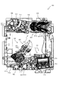
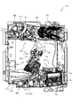
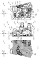
以下、本発明の実施形態について、添付図面を参照して説明する。まず、図1から図111を参照し、第1実施形態として、本発明をパチンコ遊技機(以下、単に「パチンコ機」という)10に適用した場合の一実施形態について説明する。図1は、第1実施形態におけるパチンコ機10の正面図であり、図2はパチンコ機10の遊技盤13の正面図であり、図3はパチンコ機10の背面図である。   Embodiments of the present invention will be described below with reference to the accompanying drawings. First, with reference to FIG. 1 to FIG. 111, an embodiment in which the present invention is applied to a pachinko gaming machine (hereinafter simply referred to as “pachinko machine”) 10 will be described as a first embodiment. 1 is a front view of a pachinko machine 10 according to the first embodiment, FIG. 2 is a front view of a game board 13 of the pachinko machine 10, and FIG. 3 is a rear view of the pachinko machine 10.

なお、以下の説明では、図1に示す状態のパチンコ機10に対して、紙面手前側を前方(正面)側として、紙面奥側を後方(背面)側として説明する。また、図1に示す状態のパチンコ機10に対して、上側を上方(上)側として、下側を下方(下)側として、右側を右方(右)側として、左側を左方(左)側としてそれぞれ説明する。さらに、図中の矢印U−D,L−R,F−Bは、パチンコ機10の上下方向,左右方向,前後方向をそれぞれ示している。   In the following description, the front side of the paper is the front (front) side and the back side of the paper is the rear (back) side of the pachinko machine 10 in the state shown in FIG. Also, with respect to the pachinko machine 10 shown in FIG. 1, the upper side is the upper (upper) side, the lower side is the lower (lower) side, the right side is the right (right) side, and the left side is left (left) ) Side. Furthermore, arrows UD, LR, and FB in the figure indicate the up-down direction, left-right direction, and front-rear direction of the pachinko machine 10, respectively.

図1に示すように、パチンコ機10は、略矩形状に組み合わせた木枠により外殻が形成される外枠11と、その外枠11と略同一の外形形状に形成され外枠11に対して開閉可能に支持された内枠4とを備えている。外枠11には、内枠4を支持するために正面視(図1参照)左側の上下2カ所に金属製のヒンジ18が取り付けられ、そのヒンジ18が設けられた側を開閉の軸として内枠4が正面手前側へ開閉可能に支持されている。   As shown in FIG. 1, the pachinko machine 10 includes an outer frame 11 in which an outer shell is formed by a wooden frame combined in a substantially rectangular shape, and an outer shape that is substantially the same as the outer frame 11. And an inner frame 4 supported to be openable and closable. To support the inner frame 4, metal hinges 18 are attached to the outer frame 11 at two upper and lower positions on the left side when viewed from the front (see FIG. 1), and the side on which the hinges 18 are provided is used as an opening / closing axis. The frame 4 is supported so as to be openable and closable to the front front side.

内枠4には、多数の釘や入賞口63,64等を有する遊技盤13(図2参照)が裏面側から着脱可能に装着される。この遊技盤13の前面を球(遊技球)が流下することにより弾球遊技が行われる。なお、内枠4には、球を遊技盤13の前面領域に発射する球発射ユニット112a(図4参照)やその球発射ユニット112aから発射された球を遊技盤13の前面領域まで誘導する発射レール(図示せず)等が取り付けられている。   A game board 13 (see FIG. 2) having a large number of nails, winning holes 63, 64, and the like is detachably mounted on the inner frame 4 from the back side. A ball ball game is played when a ball (game ball) flows down the front of the game board 13. The inner frame 4 has a ball launch unit 112a (see FIG. 4) that launches a ball to the front area of the game board 13 and a launch that guides the ball launched from the ball launch unit 112a to the front area of the game board 13. A rail (not shown) or the like is attached.

内枠4の前面側には、その前面上側を覆う前扉5と、その下側を覆う下皿ユニット15とが設けられている。前扉5および下皿ユニット15を支持するために正面視(図1参照)左側の上下2カ所に金属製のヒンジ19が取り付けられ、そのヒンジ19が設けられた側を開閉の軸として前扉5および下皿ユニット15が正面手前側へ開閉可能に支持されている。なお、内枠4の施錠と前扉5の施錠とは、シリンダ錠20の鍵穴21に専用の鍵を差し込んで所定の操作を行うことでそれぞれ解除される。   On the front side of the inner frame 4, a front door 5 that covers the upper side of the front surface and a lower dish unit 15 that covers the lower side thereof are provided. In order to support the front door 5 and the lower tray unit 15, metal hinges 19 are attached to two places on the left and right sides of the front view (see FIG. 1), and the front door is provided with the side on which the hinges 19 are provided as an opening / closing axis. 5 and the lower pan unit 15 are supported so as to be openable and closable toward the front front side. The locking of the inner frame 4 and the locking of the front door 5 are respectively released by inserting a dedicated key into the key hole 21 of the cylinder lock 20 and performing a predetermined operation.

前扉5は、装飾用の樹脂部品や電気部品等を組み付けたものであり、その略中央部には略楕円形状に開口形成された窓部5cが設けられている。前扉5の裏面側には2枚の板ガラス8を有するガラスユニット16が配設され、そのガラスユニット16を介して遊技盤13の前面がパチンコ機10の正面側に視認可能となっている。   The front door 5 is an assembly of decorative resin parts, electrical parts, and the like, and a window portion 5c that is formed in an approximately elliptical shape is provided at a substantially central portion thereof. A glass unit 16 having two sheet glasses 8 is disposed on the back side of the front door 5, and the front surface of the game board 13 can be visually recognized on the front side of the pachinko machine 10 through the glass unit 16.

前扉5には、球を貯留する上皿17が前方へ張り出して上面を開放した略箱状に形成されており、この上皿17に賞球や貸出球などが排出される。上皿17の底面は正面視(図1参照)右側に下降傾斜して形成され、その傾斜により上皿17に投入された球が球発射ユニット112a(図4参照)へと案内される。また、上皿17の上面には、枠ボタン22が設けられている。この枠ボタン22は、例えば、第3図柄表示装置81(図2参照)で表示される演出のステージを変更したり、スーパーリーチの演出内容を変更したりする場合などに、遊技者により操作される。   On the front door 5, an upper plate 17 that stores balls is formed in a substantially box shape that protrudes forward and has an open upper surface, and prize balls and rental balls are discharged to the upper plate 17. The bottom surface of the upper plate 17 is formed to be inclined downward to the right when viewed from the front (see FIG. 1), and the sphere thrown into the upper plate 17 is guided to the ball launch unit 112a (see FIG. 4). A frame button 22 is provided on the upper surface of the upper plate 17. The frame button 22 is operated by the player when, for example, changing the stage of the effect displayed on the third symbol display device 81 (see FIG. 2) or changing the contents of the effect of super reach. The

前扉5には、その周囲(例えばコーナー部分)に各種ランプ等の発光手段が設けられている。これら発光手段は、大当たり時や所定のリーチ時等における遊技状態の変化に応じて、点灯又は点滅することにより発光態様が変更制御され、遊技中の演出効果を高める役割を果たす。窓部5cの周縁には、LED等の発光手段を内蔵した電飾部29〜33が設けられている。パチンコ機10においては、これら電飾部29〜33が大当たりランプ等の演出ランプとして機能し、大当たり時やリーチ演出時等には内蔵するLEDの点灯や点滅によって各電飾部29〜33が点灯または点滅して、大当たり中である旨、或いは大当たり一歩手前のリーチ中である旨が報知される。また、前扉5の正面視(図1参照)左上部には、LED等の発光手段が内蔵され賞球の払い出し中とエラー発生時とを表示可能な表示ランプ34が設けられている。   The front door 5 is provided with light emitting means such as various lamps around the front door (for example, a corner portion). These light-emitting means play a role of enhancing the effect of the game during the game by changing or controlling the light-emitting mode by turning on or flashing according to the change in the gaming state at the time of big hit or predetermined reach. On the periphery of the window portion 5c, there are provided electric decoration portions 29 to 33 incorporating light emitting means such as LEDs. In the pachinko machine 10, these lighting parts 29 to 33 function as effect lamps such as jackpot lamps, and the lighting parts 29 to 33 are turned on by lighting or blinking of the built-in LEDs at the time of jackpot or reach effects. Alternatively, it blinks to notify that the jackpot is being hit or that the reach is one step before the jackpot. Further, in the upper left part of the front door 5 as viewed from the front (see FIG. 1), a light-emitting means such as an LED is incorporated, and a display lamp 34 is provided that can display when a prize ball is being paid out and when an error occurs.

また、右側の電飾部32下側には、前扉5の裏面側を視認できるように裏面側より透明樹脂を取り付けて小窓35が形成され、遊技盤13前面の貼着スペースK1(図2参照)に貼付される証紙等がパチンコ機10の前面から視認可能とされている。また、パチンコ機10においては、より煌びやかさを醸し出すために、電飾部29〜33の周りの領域にクロムメッキを施したABS樹脂製のメッキ部材36が取り付けられている。   Further, a small window 35 is formed by attaching a transparent resin from the back side so that the back side of the front door 5 can be visually recognized on the lower side of the right-side electric decoration part 32, and an adhering space K1 (see FIG. 2) can be visually recognized from the front surface of the pachinko machine 10. In addition, in the pachinko machine 10, a plated member 36 made of ABS resin that is chrome-plated is attached to an area around the electric decoration parts 29 to 33 in order to bring out more gorgeousness.

窓部5cの下方には、貸球操作部40が配設されている。貸球操作部40には、度数表示部41と、球貸しボタン42と、返却ボタン43とが設けられている。パチンコ機10の側方に配置されるカードユニット(球貸しユニット)(図示せず)に紙幣やカード等を投入した状態で貸球操作部40が操作されると、その操作に応じて球の貸出が行われる。具体的には、度数表示部41はカード等の残額情報が表示される領域であり、内蔵されたLEDが点灯して残額情報として残額が数字で表示される。球貸しボタン42は、カード等(記録媒体)に記録された情報に基づいて貸出球を得るために操作されるものであり、カード等に残額が存在する限りにおいて貸出球が上皿17に供給される。返却ボタン43は、カードユニットに挿入されたカード等の返却を求める際に操作される。なお、カードユニットを介さずに球貸し装置等から上皿17に球が直接貸し出されるパチンコ機、いわゆる現金機では貸球操作部40が不要となるが、この場合には、貸球操作部40の設置部分に飾りシール等を付加して部品構成は共通のものとしても良い。カードユニットを用いたパチンコ機と現金機との共通化を図ることができる。   A ball rental operation unit 40 is disposed below the window 5c. The ball lending operation unit 40 is provided with a frequency display unit 41, a ball lending button 42, and a return button 43. When the ball lending operation unit 40 is operated in a state where a bill or a card is inserted into a card unit (ball lending unit) (not shown) arranged on the side of the pachinko machine 10, Loans are made. Specifically, the frequency display unit 41 is an area in which the remaining amount information such as a card is displayed, and the built-in LED is lit to display the remaining amount as the remaining amount information. The ball lending button 42 is operated to obtain a lending ball based on information recorded on a card or the like (recording medium), and the lending ball is supplied to the upper plate 17 as long as there is a remaining amount on the card or the like. Is done. The return button 43 is operated when requesting the return of a card or the like inserted into the card unit. In addition, in a pachinko machine in which a ball is lent directly to the upper plate 17 from a ball lending device or the like without using a card unit, a so-called cash machine does not require the ball lending operation unit 40. In this case, the ball lending operation unit 40 It is also possible to add a decorative seal or the like to the installation portion of the parts so that the component configuration is common. A pachinko machine using a card unit and a cash machine can be shared.

上皿17の下側に位置する下皿ユニット15には、その中央部に上皿17に貯留しきれなかった球を貯留するための下皿50が上面を開放した略箱状に形成されている。下皿50の右側には、球を遊技盤13の前面へ打ち込むために遊技者によって操作される操作ハンドル51が配設される。   In the lower plate unit 15 located on the lower side of the upper plate 17, a lower plate 50 for storing a ball that could not be stored in the upper plate 17 is formed in a substantially box shape having an open upper surface. Yes. On the right side of the lower plate 50, an operation handle 51 that is operated by a player to drive a ball into the front surface of the game board 13 is disposed.

操作ハンドル51の内部には、球発射ユニット112aの駆動を許可するためのタッチセンサ51aと、押下操作している期間中には球の発射を停止する発射停止スイッチ51bと、操作ハンドル51の回動操作量(回動位置)を電気抵抗の変化により検出する可変抵抗器(図示せず)などが内蔵されている。操作ハンドル51が遊技者によって右回りに回動操作されると、タッチセンサ51aがオンされると共に可変抵抗器の抵抗値が回動操作量に対応して変化し、その可変抵抗器の抵抗値に対応した強さ(発射強度)で球が発射され、これにより遊技者の操作に対応した飛び量で遊技盤13の前面へ球が打ち込まれる。また、操作ハンドル51が遊技者により操作されていない状態においては、タッチセンサ51aおよび発射停止スイッチ51bがオフとなっている。   Inside the operation handle 51, a touch sensor 51a for permitting driving of the ball launch unit 112a, a launch stop switch 51b for stopping the launch of the ball during the pressing operation, and a rotation of the operation handle 51. A variable resistor (not shown) that detects the amount of movement (rotation position) based on a change in electrical resistance is incorporated. When the operation handle 51 is rotated clockwise by the player, the touch sensor 51a is turned on and the resistance value of the variable resistor changes in accordance with the amount of rotation operation. The resistance value of the variable resistor A ball is fired with a strength corresponding to (shooting strength), and the ball is driven into the front surface of the game board 13 with a jump amount corresponding to the player's operation. Further, when the operation handle 51 is not operated by the player, the touch sensor 51a and the firing stop switch 51b are turned off.

下皿50の正面下方部には、下皿50に貯留された球を下方へ排出する際に操作するための球抜きレバー52が設けられている。この球抜きレバー52は、常時、右方向に付勢されており、その付勢に抗して左方向へスライドさせることにより、下皿50の底面に形成された底面口が開口して、その底面口から球が自然落下して排出される。この球抜きレバー52の操作は、通常、下皿50の下方に下皿50から排出された球を受け取る箱(一般に「千両箱」と称される)を置いた状態で行われる。下皿50の右方には、上述したように操作ハンドル51が配設され、下皿50の左方には灰皿53が取り付けられている。   In the lower part of the front of the lower plate 50, a ball removal lever 52 is provided for operating when the balls stored in the lower plate 50 are discharged downward. The ball removal lever 52 is always urged in the right direction. By sliding the ball release lever 52 in the left direction against the urge, the bottom opening formed in the bottom surface of the lower plate 50 is opened. A ball naturally falls from the bottom opening and is discharged. The operation of the ball removal lever 52 is normally performed in a state where a box (generally referred to as “a thousand box”) for receiving the balls discharged from the lower plate 50 is placed below the lower plate 50. As described above, the operation handle 51 is disposed on the right side of the lower plate 50, and the ashtray 53 is attached on the left side of the lower plate 50.

図2に示すように、遊技盤13は、正面視略正方形状に切削加工したベース板60に、球案内用の多数の釘(図示せず)や風車の他、レール76,77、一般入賞口63、第1入賞口64、第2入賞口640、可変入賞装置65、第1スルーゲート66、可変表示装置ユニット80等を組み付けて構成され、その周縁部が内枠4(図1参照)の裏面側に取り付けられる。ベース板60は薄い板材を張り合わせた木材からなり、その正面側からベース板60の背面側に配設された各種構造体を遊技者に目視できないように形成される。一般入賞口63、第1入賞口64、第2入賞口640、可変入賞装置65、可変表示装置ユニット80は、ルータ加工によってベース板60に形成された貫通穴に配設され、遊技盤13の前面側からタッピングネジ等により固定されている。   As shown in FIG. 2, the game board 13 includes a base plate 60 cut into a substantially square shape when viewed from the front, a large number of nails (not shown) for ball guidance, a windmill, rails 76 and 77, and a general prize. The opening 63, the first winning port 64, the second winning port 640, the variable winning device 65, the first through gate 66, the variable display device unit 80 and the like are assembled, and the peripheral portion thereof is the inner frame 4 (see FIG. 1). It is attached to the back side. The base plate 60 is made of wood on which thin plate materials are laminated, and is formed so that various structures disposed on the back side of the base plate 60 from the front side cannot be seen by the player. The general winning port 63, the first winning port 64, the second winning port 640, the variable winning device 65, and the variable display device unit 80 are disposed in a through hole formed in the base plate 60 by router processing. It is fixed from the front side with a tapping screw or the like.

遊技盤13の前面中央部分は、前扉5の窓部5c(図1参照)を通じて内枠4の前面側から視認することができる。以下に、主に図2を参照して、遊技盤13の構成について説明する。   The front center portion of the game board 13 can be viewed from the front side of the inner frame 4 through the window portion 5c (see FIG. 1) of the front door 5. The configuration of the game board 13 will be described below mainly with reference to FIG.

遊技盤13の前面には、帯状の金属板を略円弧状に屈曲加工して形成した外レール77が植立され、その外レール77の内側位置には外レール77と同様に帯状の金属板で形成した円弧状の内レール76が植立される。この内レール76と外レール77とにより遊技盤13の前面外周が囲まれ、遊技盤13とガラスユニット16(図1参照)とにより前後が囲まれることにより、遊技盤13の前面には、球の挙動により遊技が行われる遊技領域が形成される。遊技領域は、遊技盤13の前面であって2本のレール76,77とレール間を繋ぐ樹脂製の外縁部材73とにより区画して形成される領域(入賞口等が配設され、発射された球が流下する領域)である。   An outer rail 77 formed by bending a strip-shaped metal plate into a substantially arc shape is planted on the front surface of the game board 13, and the strip-shaped metal plate is located at an inner position of the outer rail 77 in the same manner as the outer rail 77. The arc-shaped inner rail 76 formed in the above is planted. The outer periphery of the front surface of the game board 13 is surrounded by the inner rail 76 and the outer rail 77, and the front and rear are surrounded by the game board 13 and the glass unit 16 (see FIG. 1). A game area in which a game is played is formed by the behavior of. The game area is an area formed on the front surface of the game board 13 and defined by two rails 76 and 77 and a resin outer edge member 73 that connects the rails (a winning opening is provided and fired). Area where the falling sphere flows).

2本のレール76,77は、球発射ユニット112a(図4参照)から発射された球を遊技盤13上部へ案内するために設けられたものである。内レール76の先端部分(図2の左上部)には戻り球防止部材68が取り付けられ、一旦、遊技盤13の上部へ案内された球が再度球案内通路内に戻ってしまうといった事態が防止される。外レール77の先端部(図2の右上部)には、球の最大飛翔部分に対応する位置に返しゴム69が取り付けられ、所定以上の勢いで発射された球は、返しゴム69に当たって、勢いが減衰されつつ中央部側へ跳ね返される。   The two rails 76 and 77 are provided to guide the ball fired from the ball launching unit 112a (see FIG. 4) to the upper part of the game board 13. A return ball prevention member 68 is attached to the front end portion of the inner rail 76 (the upper left portion in FIG. 2) to prevent the ball once guided to the upper part of the game board 13 from returning to the ball guide path again. Is done. A return rubber 69 is attached to the tip of the outer rail 77 (upper right part in FIG. 2) at a position corresponding to the maximum flying portion of the sphere, and the ball launched at a predetermined momentum or more hits the return rubber 69 and gains momentum. Is bounced back to the center while being attenuated.

遊技領域の正面視左側下部(図2の左側下部)には、発光手段である複数のLEDおよび7セグメント表示器を備える第1図柄表示装置37A,37Bが配設されている。第1図柄表示装置37A,37Bは、主制御装置110(図4参照)で行われる各制御に応じた表示がなされるものであり、主にパチンコ機10の遊技状態の表示が行われる。本実施形態では、第1図柄表示装置37A,37Bは、球が、第1入賞口64へ入賞したか、第2入賞口640へ入賞したかに応じて使い分けられるように構成されている。具体的には、球が、第1入賞口64へ入賞した場合には、第1図柄表示装置37Aが作動し、一方で、球が、第2入賞口640へ入賞した場合には、第1図柄表示装置37Bが作動するように構成されている。   A first symbol display device 37A, 37B including a plurality of LEDs serving as light emitting means and a 7-segment display is disposed in the lower left portion of the game area when viewed from the front (lower left portion in FIG. 2). The first symbol display devices 37A and 37B display according to each control performed by the main control device 110 (see FIG. 4), and mainly display the gaming state of the pachinko machine 10. In the present embodiment, the first symbol display devices 37 </ b> A and 37 </ b> B are configured to be selectively used depending on whether the ball has won the first prize opening 64 or the second prize opening 640. Specifically, when the ball wins the first winning opening 64, the first symbol display device 37A operates, while when the ball wins the second winning opening 640, the first symbol display device 37A operates. The symbol display device 37B is configured to operate.

また、第1図柄表示装置37A,37Bは、LEDにより、パチンコ機10が確変中か時短中か通常中であるかを点灯状態により示したり、変動中であるか否かを点灯状態により示したり、停止図柄が確変大当たりに対応した図柄か普通大当たりに対応した図柄か外れ図柄であるかを点灯状態により示したり、保留球数を点灯状態により示すと共に、7セグメント表示装置により、大当たり中のラウンド数やエラー表示を行う。なお、複数のLEDは、それぞれのLEDの発光色(例えば、赤、緑、青)が異なるよう構成され、その発光色の組み合わせにより、少ないLEDでパチンコ機10の各種遊技状態を示唆することができる。   In addition, the first symbol display devices 37A and 37B indicate, by means of LEDs, whether the pachinko machine 10 is in the process of changing the probability, in the short time, or in the normal state by a lighting state, or whether the pachinko machine 10 is changing or not by a lighting state. , Indicating whether the stop symbol is a symbol corresponding to a probable jackpot, a symbol corresponding to a normal jackpot, or a symbol that is out of place by a lighting state, indicating the number of held balls by a lighting state, and a 7-segment display device, Displays numbers and errors. The plurality of LEDs are configured to have different emission colors (for example, red, green, and blue) of each LED, and the combination of the emission colors may suggest various gaming states of the pachinko machine 10 with a small number of LEDs. it can.

なお、本パチンコ機10では、第1入賞口64,第2入賞口640のいずれかに入賞があったことを契機として抽選が行われる。パチンコ機10は、その抽選において、大当たりか否かの当否判定(大当たり抽選)を行うと共に、大当たりと判定した場合はその大当たり種別の判定も行う。ここで判定される大当たり種別としては、15R確変大当たり、4R確変大当たり、15R通常大当たりが用意されている。第1図柄表示装置37A,37Bには、変動終了後の停止図柄として抽選の結果が大当たりであるか否かが示されるだけでなく、大当たりである場合はその大当たり種別に応じた図柄が示される。   In the present pachinko machine 10, a lottery is performed in response to a winning in either the first winning port 64 or the second winning port 640. In the lottery, the pachinko machine 10 determines whether or not it is a big hit (big hit lottery), and also determines the type of the big hit if it is determined to be a big hit. As the jackpot type determined here, 15R probability variation jackpot, 4R probability variation jackpot, and 15R normal jackpot are prepared. The first symbol display devices 37A and 37B not only indicate whether or not the lottery result is a jackpot as a stop symbol after the end of the variation, but if it is a jackpot, a symbol corresponding to the jackpot type is displayed. .

ここで、「15R確変大当たり」とは、最大ラウンド数が15ラウンドの大当たりの後に高確率状態へ移行する確変大当たりのことであり、「4R確変大当たり」とは、最大ラウンド数が4ラウンドの大当たりの後に高確率状態へ移行する確変大当たりのことである。また、「15R通常大当たり」は、最大ラウンド数が15ラウンドの大当たりの後に、低確率状態へ移行すると共に、所定の変動回数の間(例えば、100変動回数)は時短状態となる大当たりのことである。   Here, the “15R probability variation jackpot” is a probability variation jackpot in which the maximum number of rounds shifts to a high probability state after a jackpot of 15 rounds, and “4R probability variation jackpot” is a jackpot with a maximum number of rounds of four. It is a probabilistic jackpot that shifts to a high probability state after. In addition, “15R normal jackpot” is a jackpot that shifts to a low probability state after the maximum number of rounds of 15 rounds and hits a short time during a predetermined number of fluctuations (for example, 100 fluctuations). is there.

また、「高確率状態」とは、大当たり終了後に付加価値としてその後の大当たり確率がアップした状態、いわゆる確率変動中(確変中)の時をいい、換言すれば、特別遊技状態へ移行し易い遊技の状態のことである。本実施形態における高確率状態(確変中)は、後述する第2図柄の当たり確率がアップして第2入賞口640へ球が入賞し易い遊技の状態を含む。「低確率状態」とは、確変中でない時をいい、大当たり確率が通常の状態、即ち、確変の時より大当たり確率が低い状態をいう。また、「低確率状態」のうちの時短状態(時短中)とは、大当たり確率が通常の状態であると共に、大当たり確率がそのままで第2図柄の当たり確率のみがアップして第2入賞口640へ球が入賞し易い遊技の状態のことをいう。一方、パチンコ機10が通常中とは、確変中でも時短中でもない遊技の状態(大当たり確率も第2図柄の当たり確率もアップしていない状態)である。   In addition, the “high probability state” means a state in which the jackpot probability thereafter increases as an added value after the jackpot ends, that is, when the probability change is in progress (probability change), in other words, a game that easily shifts to the special game state. It is a state of. The high probability state (during probability change) in the present embodiment includes a game state in which the hit probability of the second symbol, which will be described later, is increased and the ball is likely to win the second winning opening 640. The “low probability state” refers to a time when the probability of jackpot change is not occurring, and a state where the jackpot probability is normal, that is, a state where the jackpot probability is lower than that at the time of probability change. The short time state (short time medium) of the “low probability state” means that the jackpot probability is a normal state, and the jackpot probability remains as it is, and only the hit probability of the second symbol is increased, and the second prize opening 640 is obtained. It means the state of the game where the ball is easy to win. On the other hand, when the pachinko machine 10 is in a normal state is a game state (a state where neither the big hit probability nor the second symbol hit probability is increased) which is neither probabilistic nor short in time.

確変中や時短中は、第2図柄の当たり確率がアップするだけではなく、第2入賞口640に付随する第1電動役物640aが開放される時間も変更され、通常中と比して長い時間が設定される。第1電動役物640aが開放された状態(開放状態)にある場合は、その第1電動役物640aが閉鎖された状態(閉鎖状態)にある場合と比して、第2入賞口640へ球が入賞しやすい状態となる。よって、確変中や時短中は、第2入賞口640へ球が入賞し易い状態となり、大当たり抽選が行われる回数を増やすことができる。   During probability change and short time, not only does the probability of winning the second symbol increase, but also the time for opening the first electric accessory 640a associated with the second winning opening 640 is changed, which is longer than normal. Time is set. When the first electric combination 640a is in the opened state (open state), the second prize opening 640 is compared with the case where the first electric combination 640a is in the closed state (closed state). The ball is ready to win. Therefore, during the probability change or the short time, it becomes easy for the ball to win the second winning opening 640, and the number of jackpot lotteries can be increased.

なお、確変中や時短中において、第2入賞口640に付随する第1電動役物640aの開放時間を変更するのではなく、または、その開放時間を変更することに加えて、1回の当たりで第1電動役物640aが開放する回数を通常中よりも増やす変更を行うものとしてもよい。また、確変中や時短中において、第2図柄の当たり確率は変更せず、第2入賞口640に付随する第1電動役物640aが開放される時間および1回の当たりで第1電動役物640aが開放する回数の少なくとも一方を変更するものとしてもよい。また、確変中や時短中において、第2入賞口640に付随する第1電動役物640aが開放される時間や、1回の当たりで第1電動役物640aを開放する回数は変更せず、第2図柄の当たり確率だけを、通常中と比してアップするよう変更するものであってもよい。   In addition, during the probability change or during the short time, instead of changing the opening time of the first electric accessory 640a attached to the second prize opening 640, or in addition to changing the opening time, Thus, the number of times the first electric accessory 640a is opened may be changed to be larger than normal. In addition, the probability of winning the second symbol is not changed during the probability change or in the short time, and the first electric accessory is determined at the time when the first electric accessory 640a attached to the second winning opening 640 is opened and once. It is good also as what changes at least one of the frequency | count that 640a opens. In addition, during the probability change and in the short time, the time for opening the first electric combination 640a associated with the second prize opening 640 and the number of times of opening the first electric combination 640a per change are not changed. Only the probability of hitting the second symbol may be changed so as to increase compared to the normal probability.

遊技領域には、球が入賞することにより5個から15個の球が賞球として払い出される複数の一般入賞口63が配設されている。また、遊技領域の中央部分には、可変表示装置ユニット80が配設されている。可変表示装置ユニット80には、第1入賞口64、第2入賞口640のいずれかの入賞(始動入賞)をトリガとして、第1図柄表示装置37A,37Bにおける変動表示と同期させながら、第3図柄の変動表示を行う液晶ディスプレイ(以下単に「表示装置」と略す)で構成された第3図柄表示装置81と、第1スルーゲート66の球の通過をトリガとして第2図柄を変動表示するLEDで構成される第2図柄表示装置(図示せず)とが設けられている。   The game area is provided with a plurality of general winning ports 63 through which 5 to 15 balls are paid out as winning balls when the balls win. In addition, a variable display device unit 80 is disposed in the central portion of the game area. The variable display device unit 80 is synchronized with the variable display on the first symbol display devices 37A and 37B, triggered by any one of the first winning port 64 and the second winning port 640 (starting winning) as a trigger. A third symbol display device 81 composed of a liquid crystal display (hereinafter simply abbreviated as “display device”) for displaying the symbols in a variable manner, and an LED for variably displaying the second symbols with the passage of the first through gate 66 as a trigger. The 2nd symbol display apparatus (not shown) comprised by these is provided.

また、可変表示装置ユニット80には、第3図柄表示装置81の外周を囲むようにして、センターフレーム86が配設されている。このセンターフレーム86の中央に開口される開口部から第3図柄表示装置81が視認可能とされる。   The variable display device unit 80 is provided with a center frame 86 so as to surround the outer periphery of the third symbol display device 81. The third symbol display device 81 is visible through an opening opened in the center of the center frame 86.

第3図柄表示装置81は9インチサイズの大型の液晶ディスプレイで構成されるものであり、表示制御装置114(図4参照)によって表示内容が制御されることにより、例えば上、中および下の3つの図柄列が表示される。各図柄列は複数の図柄(第3図柄)によって構成され、これらの第3図柄が図柄列毎に横スクロールして第3図柄表示装置81の表示画面上にて第3図柄が可変表示されるようになっている。本実施形態の第3図柄表示装置81は、主制御装置110(図4参照)の制御に伴った遊技状態の表示が第1図柄表示装置37A,37Bで行われるのに対して、その第1図柄表示装置37A,37Bの表示に応じた装飾的な表示を行うものである。なお、表示装置に代えて、例えばリール等を用いて第3図柄表示装置81を構成するようにしても良い。   The third symbol display device 81 is constituted by a large 9-inch liquid crystal display, and the display content is controlled by the display control device 114 (see FIG. 4). One symbol row is displayed. Each symbol row is composed of a plurality of symbols (third symbol). These third symbols are horizontally scrolled for each symbol column, and the third symbol is variably displayed on the display screen of the third symbol display device 81. It is like that. In the third symbol display device 81 of the present embodiment, the game state display associated with the control of the main controller 110 (see FIG. 4) is performed on the first symbol display devices 37A and 37B. The decorative display according to the display of the symbol display devices 37A and 37B is performed. Instead of the display device, the third symbol display device 81 may be configured using, for example, a reel.

第2図柄表示装置は、球が第1スルーゲート66を通過する毎に表示図柄(第2図柄(図示せず))としての「○」の図柄と「×」の図柄とを所定時間交互に点灯させる変動表示を行うものである。パチンコ機10では、球が第1スルーゲート66を通過したことが検出されると、当たり抽選が行われる。その当たり抽選の結果、当たりであれば、第2図柄表示装置において、第2図柄の変動表示後に「○」の図柄が停止表示される。また、当たり抽選の結果、外れであれば、第2図柄表示装置において、第3図柄の変動表示後に「×」の図柄が停止表示される。   Each time the sphere passes through the first through gate 66, the second symbol display device alternately displays a symbol “◯” and a symbol “X” as a display symbol (second symbol (not shown)) for a predetermined time. The variable display to light is performed. In the pachinko machine 10, when it is detected that the ball has passed through the first through gate 66, a winning lottery is performed. As a result of the winning lottery, if the winning symbol is a winning symbol, the symbol “◯” is stopped and displayed on the second symbol display device after the variation of the second symbol is displayed. Further, if the winning lottery results, the symbol of “x” is stopped and displayed on the second symbol display device after the variation of the third symbol is displayed.

パチンコ機10は、第2図柄表示装置における変動表示が所定図柄(本実施形態においては「○」の図柄)で停止した場合に、第2入賞口640に付随された第1電動役物640aが所定時間だけ作動状態となる(開放される)よう構成されている。   In the pachinko machine 10, when the variable display on the second symbol display device stops at a predetermined symbol (in this embodiment, a symbol “◯”), the first electric accessory 640a attached to the second winning opening 640 is displayed. It is configured to be activated (opened) for a predetermined time.

第2図柄の変動表示にかかる時間は、遊技状態が通常中の場合よりも、確変中または時短中の方が短くなるように設定される。これにより、確変中および時短中は、第2図柄の変動表示が短い時間で行われるので、当たり抽選を通常中よりも多く行うことができる。よって、当たり抽選において当たりとなる機会が増えるので、第2入賞口640の第1電動役物640aが開放状態となる機会を遊技者に多く与えることができる。よって、確変中および時短中は、第2入賞口640へ球が入賞しやすい状態とすることができる。   The time required for the variable display of the second symbol is set to be shorter during the probability change or during the shorter time than when the game state is normal. As a result, during the probability change and during the time reduction, since the variation display of the second symbol is performed in a short time, the winning lottery can be performed more than during normal. Therefore, since the chances for winning in the winning lottery increase, the player can be given many opportunities for the first electric accessory 640a of the second winning opening 640 to be in an open state. Therefore, it is possible to make it easier for the ball to win the second winning opening 640 during the probability change and during the short time.

なお、確変中または時短中において、当たり確率を高める、1回に当たりに対する第1電動役物640aの開放時間や開放回数を増やすなど、その他の方法によっても、確変中または時短中に第2入賞口640へ球が入賞しやすい状態としている場合は、第2図柄の変動表示にかかる時間を遊技状態にかかわらず一定としてもよい。一方、第2図柄の変動表示にかかる時間を、確変中または時短中において通常中よりも短く設定する場合は、当たり確率を遊技状態にかかわらず一定にしてもよいし、また、1回の当たりに対する第1電動役物640aの開放時間や開放回数を遊技状態にかかわらず一定にしてもよい。   In addition, during the probability change or in the short time, the second winning a prize opening during the probability change or in the short time can also be achieved by other methods such as increasing the probability of winning during the time of the change or increasing the number of times the first electric accessory 640a is released per time. When it is in a state where it is easy to win a ball to 640, the time required for the variable display of the second symbol may be constant regardless of the gaming state. On the other hand, when the time required for displaying the variation of the second symbol is set shorter than normal during probability change or short time, the winning probability may be constant regardless of the gaming state, The opening time and the number of opening times of the first electric accessory 640a may be constant regardless of the gaming state.

第1スルーゲート66は、可変表示装置ユニット80の右側の領域において遊技盤に組み付けられる。第1スルーゲート66は、遊技盤に発射された球のうち、遊技盤を流下する球の一部が通過可能に構成されている。第1スルーゲート66を球が通過すると、第2図柄の当たり抽選が行われる。当たり抽選の後、第2図柄表示装置にて変動表示を行い、当たり抽選の結果が当たりであれば、変動表示の停止図柄として「○」の図柄を表示し、当たり抽選の結果が外れであれば、変動表示の停止図柄として「×」の図柄を表示する。   The first through gate 66 is assembled to the game board in the area on the right side of the variable display device unit 80. The first through gate 66 is configured to allow passage of a part of the ball that flows down the game board out of the balls fired on the game board. When the ball passes through the first through gate 66, the lottery of the second symbol is performed. After winning the lottery, the 2nd symbol display device displays the variation. For example, the symbol “x” is displayed as the stop symbol of the variable display.

球の第1スルーゲート66の通過回数は、合計で最大4回まで保留され、その保留球数が上述した第1図柄表示装置37A,37Bにより表示されると共に第2図柄保留ランプ(図示せず)においても点灯表示される。第2図柄保留ランプは、最大保留数分の4つ設けられ、第3図柄表示装置81の下方に左右対称に配設されている。   The total number of passages of the first through gate 66 of the sphere is reserved up to a total of four times, and the number of retained balls is displayed by the above-described first symbol display devices 37A and 37B and a second symbol hold lamp (not shown). ) Is also lit. Four second symbol holding lamps are provided for the maximum number of holdings, and are arranged symmetrically below the third symbol display device 81.

なお、第2図柄の変動表示は、本実施形態のように、第2図柄表示装置において複数のランプの点灯と非点灯を切り換えることにより行うものの他、第1図柄表示装置37A,37Bおよび第3図柄表示装置81の一部を使用して行うようにしても良い。同様に、第2図柄保留ランプの点灯を第3図柄表示装置81の一部で行うようにしても良い。また、第1スルーゲート66の球の通過に対する最大保留球数は4回に限定されるものでなく、3回以下、又は、5回以上の回数(例えば、8回)に設定しても良い。また、スルーゲートの組み付け数は2つに限定されるものではなく、3つ以上の複数であっても良い。また、スルーゲートの組み付け位置は可変表示装置ユニット80の左右両側に限定されるものではなく、例えば、可変表示装置ユニット80の下方でも良い。また、第1図柄表示装置37A,37Bにより保留球数が示されるので、第2図柄保留ランプにより点灯表示を行わないものとしてもよい。   In addition, the variable display of the second symbol is performed by switching on and off of a plurality of lamps in the second symbol display device as in the present embodiment, as well as the first symbol display devices 37A and 37B and the third symbol. A part of the symbol display device 81 may be used. Similarly, the second symbol holding lamp may be turned on by a part of the third symbol display device 81. Further, the maximum number of balls held for passing the ball of the first through gate 66 is not limited to 4 times, and may be set to 3 times or less, or 5 times or more (for example, 8 times). . Further, the number of through gates to be assembled is not limited to two, and may be three or more. Further, the assembly position of the through gate is not limited to the left and right sides of the variable display device unit 80, and may be, for example, below the variable display device unit 80. In addition, since the number of reserved balls is indicated by the first symbol display devices 37A and 37B, the second symbol hold lamp may not perform lighting display.

可変表示装置ユニット80の下方には、球が入賞し得る第1入賞口64が配設されている。この第1入賞口64へ球が入賞すると遊技盤13の裏面側に設けられる第1入賞口スイッチ(図示せず)がオンとなり、その第1入賞口スイッチのオンに起因して主制御装置110(図4参照)で大当たりの抽選がなされ、その抽選結果に応じた表示が第1図柄表示装置37Aで示される。   Below the variable display unit 80, a first winning port 64 through which a ball can win is disposed. When a ball wins the first winning port 64, a first winning port switch (not shown) provided on the back side of the game board 13 is turned on, and the main controller 110 is caused by the first winning port switch being turned on. A jackpot lottery is made (see FIG. 4), and a display corresponding to the lottery result is shown on the first symbol display device 37A.

一方、第1入賞口64の正面視右方には、球が入賞し得る第2入賞口640が配設されている。第2入賞口640へ球が入賞すると遊技盤13の裏面側に設けられる第2入賞口スイッチ(図示せず)がオンとなり、その第2入賞口スイッチのオンに起因して主制御装置110(図4参照)で大当たりの抽選がなされ、その抽選結果に応じた表示が第1図柄表示装置37Bで示される。   On the other hand, a second winning port 640 through which a ball can win is disposed on the right side of the first winning port 64 in front view. When a ball wins the second winning port 640, a second winning port switch (not shown) provided on the back side of the game board 13 is turned on, and the main controller 110 ( (See FIG. 4), the jackpot lottery is made, and the display corresponding to the lottery result is shown by the first symbol display device 37B.

また、第1入賞口64,第2入賞口640は、それぞれ、球が入賞すると5個の球が賞球として払い出される入賞口の1つにもなっている。なお、本実施形態においては、第1入賞口64へ球が入賞した場合に払い出される賞球数と第2入賞口640へ球が入賞した場合に払い出される賞球数とを同じに構成したが、第1入賞口64へ球が入賞した場合に払い出される賞球数と第2入賞口640へ球が入賞した場合に払い出される賞球数とを異なる数、例えば、第1入賞口64へ球が入賞した場合に払い出される賞球数を3個とし、第2入賞口640へ球が入賞した場合に払い出される賞球数を5個として構成してもよい。   In addition, each of the first winning port 64 and the second winning port 640 is also one of the winning ports through which five balls are paid out as winning balls when a ball is won. In the present embodiment, the number of prize balls to be paid out when a ball wins the first prize opening 64 and the number of prize balls to be paid out when a ball wins the second prize slot 640 are configured to be the same. The number of prize balls to be paid out when a ball wins the first prize opening 64 is different from the number of prize balls to be paid out when a ball wins to the second prize opening 640, for example, the ball to the first prize opening 64 The number of prize balls to be paid out when a prize is won may be three, and the number of prize balls to be paid out when a ball wins the second prize opening 640 may be five.

さらに、第1入賞口64の正面視左側には、球が入賞し得る第3入賞口82が配設されている。第3入賞口82は、球が入賞すると送球ユニット600を介して後述する振分けユニット500の第1開口511へ入賞した球を送球することができる。即ち、第3入賞口82は後述する第1開口511と連通した状態で配置されている。   Further, on the left side of the first winning port 64 in front view, a third winning port 82 through which a ball can win is disposed. When the ball wins, the third winning port 82 can send the winning ball to the first opening 511 of the sorting unit 500 described later via the pitching unit 600. That is, the third winning opening 82 is disposed in communication with a first opening 511 described later.

第3入賞口82には第3電動役物82aが付随されている。この第3電動役物82aは、遊技盤13に対して回転変位して開閉可能に構成されており、通常は第3電動役物82aが閉鎖状態(縮小状態)となって球が第3入賞口82へ入賞し難い状態となっている。一方、第1入賞口64又は第2入賞口640の入賞を契機とする大当たりの判定があった場合、その大当たり前、後、又は大当たり中に、第3電動役物82aが所定時間開放(拡大状態)となり、球が第3入賞口82へ入賞しやすい状態となる。また、第3入賞口82の下流側には、通過した球を検出するセンサ装置SE1が搭載される。   The third winning combination port 82 is accompanied by a third electric accessory 82a. The third electric accessory 82a is configured to be able to open and close by being rotationally displaced with respect to the game board 13. Normally, the third electric accessory 82a is in a closed state (reduced state) and the ball is in the third prize. It is difficult to win a prize in the mouth 82. On the other hand, if there is a jackpot determination triggered by winning of the first winning port 64 or the second winning port 640, the third electric accessory 82a is opened (expanded) before, after, or during the jackpot. State), and the ball is likely to enter the third winning opening 82. In addition, a sensor device SE1 for detecting a passed ball is mounted on the downstream side of the third winning award port 82.

なお、第3電動役物82aの開放のタイミングは、第1入賞口64及び第2入賞口5640の入賞を契機にして行われるものでなくても良く、第1スルーゲート66寝の球の通過を契機として行われる第2図柄の変動表示の結果、「○」の図柄が第2図柄表示装置に表示された場合、開放されるものであっても良い。   The opening timing of the third electric accessory 82a does not have to be triggered by the winning of the first winning port 64 and the second winning port 5640, and the first through gate 66 passes the sleeping ball. As a result of the change display of the second symbol performed as a trigger, when the symbol “◯” is displayed on the second symbol display device, it may be released.

第2入賞口640には第1電動役物640aが付随されている。この第1電動役物640aは開閉可能に構成されており、通常は第1電動役物640aが閉鎖状態(縮小状態)となって、球が第2入賞口640へ入賞しにくい状態となっている。一方、第1スルーゲート66への球の通過を契機として行われる第2図柄の変動表示の結果、「○」の図柄が第2図柄表示装置に表示された場合、第1電動役物640aが開放状態(拡大状態)となり、球が第2入賞口640へ入賞しやすい状態となる。   The first winning combination 640a is attached to the second winning opening 640. The first electric combination 640a is configured to be openable and closable. Normally, the first electric combination 640a is in a closed state (reduced state), and the ball is unlikely to win the second winning opening 640. Yes. On the other hand, when the symbol “◯” is displayed on the second symbol display device as a result of the variation display of the second symbol that is triggered by the passage of the ball to the first through gate 66, the first electric accessory 640 a is The open state (enlarged state) is entered, and the ball is in a state where it is easy to win the second winning opening 640.

上述した通り、確変中および時短中は、通常中と比して第2図柄の当たり確率が高く、また、第2図柄の変動表示にかかる時間も短いので、第2図柄の変動表示において「○」の図柄が表示され易くなって、第1電動役物640aが開放状態(拡大状態)となる回数が増える。更に、確変中または時短中は、第1電動役物640aが開放される時間も、通常中より長くなる。よって、確変中または時短中は、通常時と比して、第2入賞口640へ球が入賞しやすい状態を作ることができる。   As described above, the probability of hitting the second symbol is higher than that during normal change during the probability change and the short time, and the time required for the variation display of the second symbol is short. "Is easily displayed, and the number of times that the first electric accessory 640a is opened (enlarged) is increased. Furthermore, during the time of probability change or time reduction, the time during which the first electric accessory 640a is opened also becomes longer than during normal time. Therefore, it is possible to make it easier for the ball to win the second winning opening 640 when the probability is changing or when the time is short.

ここで、第1入賞口64に球が入賞した場合と第2入賞口640へ球が入賞した場合とで、大当たりとなる確率は、低確率状態であっても高確率状態でも同一である。しかしながら、大当たりとなった場合に選定される大当たりの種別として15R確変大当たりとなる確率は、第2入賞口640へ球が入賞した場合のほうが第1入賞口64へ球が入賞した場合よりも高く設定されている。一方、第1入賞口64は、第2入賞口640にあるような第1電動役物640aは有しておらず、球が常時入賞可能な状態となっている。   Here, the probability of winning a big hit is the same in both the low probability state and the high probability state when the ball wins the first winning port 64 and when the ball wins the second winning port 640. However, the probability that a 15R probability variation jackpot is selected as the jackpot type selected when the jackpot is won is higher when the ball wins the second winning slot 640 than when the ball wins the first winning slot 64. Is set. On the other hand, the first winning port 64 does not have the first electric accessory 640a as in the second winning port 640, and the ball is in a state where the ball can always be won.

よって、通常中においては、第2入賞口640に付随する電動役物が閉鎖状態にある場合が多く、第2入賞口640に入賞しづらいので、電動役物のない第1入賞口64へ向けて、可変表示装置ユニット80の左方を球が通過するように球を発射し(所謂「左打ち」)、第1入賞口64への入賞によって大当たり抽選の機会を多く得て、大当たりとなることを狙った方が、遊技者にとって有利となる。   Therefore, during normal times, the electric winnings associated with the second winning opening 640 are often in a closed state, and it is difficult to win the second winning opening 640. Then, the ball is fired so that the ball passes to the left of the variable display device unit 80 (so-called “left-handed”), and a lot of opportunities for lottery wins are obtained by winning at the first winning opening 64, and the jackpot It is advantageous for the player to aim for this.

一方、確変中や時短中は、第1スルーゲート66に球を通過させることで、第2入賞口640に付随する第1電動役物640aが開放状態となりやすく、第2入賞口640に入賞しやすい状態であるので、第2入賞口640へ向けて、可変表示装置ユニット80の右方を球が通過するように球を発射し(所謂「右打ち」)、第1スルーゲート66を通過させて第1電動役物640aを開放状態にすると共に、第2入賞口640への入賞によって15R確変大当たりとなることを狙った方が、遊技者にとって有利となる。   On the other hand, during a certain change or in a short time, passing the ball through the first through gate 66 makes it easy for the first electric accessory 640a attached to the second winning opening 640 to be in an open state, and wins the second winning opening 640. Since it is in an easy state, the ball is fired toward the second prize opening 640 so that the ball passes the right side of the variable display device unit 80 (so-called “right-handed”), and the first through gate 66 is allowed to pass. Thus, it is advantageous for the player to open the first electric combination 640a and aim for a 15R probability variation big win by winning the second winning opening 640.

このように、本実施形態のパチンコ機10は、パチンコ機10の遊技状態(確変中であるか、時短中であるか、通常中であるか)に応じて、遊技者に対し、球の発射の仕方を「左打ち」と「右打ち」とに変えさせることができる。よって、遊技者に対して、球の打ち方に変化をもたらすことができるので、遊技を楽しませることができる。   As described above, the pachinko machine 10 according to the present embodiment launches a ball to the player in accordance with the gaming state of the pachinko machine 10 (whether it is probable, short, or normal). Can be changed between “left-handed” and “right-handed”. Thus, the player can be changed in the way the ball is hit, so that the game can be enjoyed.

第1入賞口64の右側には可変入賞装置65が配設されており、その略中央部分に横長矩形状の特定入賞口(大開放口)65aが設けられている。パチンコ機10においては、第1入賞口64,第2入賞口640のいずれかの入賞に起因して行われた大当たり抽選が大当たりとなると、所定時間(変動時間)が経過した後に、大当たりの停止図柄となるよう第1図柄表示装置37A又は第1図柄表示装置37Bを点灯させると共に、その大当たりに対応した停止図柄を第3図柄表示装置81に表示させて、大当たりの発生が示される。その後、球が入賞し易い特別遊技状態(大当たり)に遊技状態が遷移する。この特別遊技状態として、通常時には閉鎖されている特定入賞口65aが、所定時間(例えば、30秒経過するまで、或いは、球が10個入賞するまで)開放される。   A variable winning device 65 is disposed on the right side of the first winning port 64, and a horizontally-long rectangular specific winning port (large opening) 65a is provided at a substantially central portion thereof. In the pachinko machine 10, when the jackpot lottery performed due to the winning of either the first winning port 64 or the second winning port 640 is a jackpot, the jackpot is stopped after a predetermined time (variable time) has elapsed. The first symbol display device 37A or the first symbol display device 37B is turned on so as to be a symbol, and a stop symbol corresponding to the jackpot is displayed on the third symbol display device 81 to indicate the occurrence of a jackpot. Thereafter, the gaming state transitions to a special gaming state (big hit) where the ball is easy to win. In this special gaming state, the special winning opening 65a that is normally closed is opened for a predetermined time (for example, until 30 seconds have elapsed or ten balls have been won).

この特定入賞口65aは、所定時間が経過すると閉鎖され、その閉鎖後、再度、その特定入賞口65aが所定時間開放される。この特定入賞口65aの開閉動作は、最高で例えば15回(15ラウンド)繰り返し可能にされている。この開閉動作が行われている状態が、遊技者にとって有利な特別遊技状態の一形態であり、遊技者には、遊技上の価値(遊技価値)の付与として通常時より多量の賞球の払い出しが行われる。   The specific winning opening 65a is closed when a predetermined time elapses, and after the closing, the specific winning opening 65a is opened again for a predetermined time. The opening / closing operation of the specific winning opening 65a can be repeated up to 15 times (15 rounds), for example. The state in which the opening / closing operation is performed is one form of a special gaming state that is advantageous to the player. Is done.

可変入賞装置65は、具体的には、特定入賞口65aを覆う横長矩形状の開閉板と、その開閉板の下辺を軸として前方側に開閉駆動するための大開放口ソレノイド(図示せず)とを備えている。特定入賞口65aは、通常時は、球が入賞できないか又は入賞し難い閉状態になっている。大当たりの際には大開放口ソレノイドを駆動して開閉板を前面下側に傾倒し、球が特定入賞口65aに入賞しやすい開状態を一時的に形成し、その開状態と通常時の閉状態との状態を交互に繰り返すように作動する。   Specifically, the variable winning device 65 includes a horizontally long rectangular opening / closing plate that covers the specific winning opening 65a, and a large opening solenoid (not shown) for opening and closing forward with the lower side of the opening / closing plate as an axis. And. The special winning opening 65a is normally closed so that the ball cannot win or is difficult to win. In the case of a big hit, the large opening opening solenoid is driven to tilt the opening / closing plate to the lower front side to temporarily form an open state in which the ball is likely to win the specific winning opening 65a. It operates to repeat the state and the state alternately.

なお、上記した形態に特別遊技状態は限定されるものではない。特定入賞口65aとは別に開閉される大開放口を遊技領域に設け、第1図柄表示装置37A,37Bにおいて大当たりに対応したLEDが点灯した場合に、特定入賞口65aが所定時間開放され、その特定入賞口65aの開放中に、球が特定入賞口65a内へ入賞することを契機として特定入賞口65aとは別に設けられた大開放口が所定時間、所定回数開放される遊技状態を特別遊技状態として形成するようにしても良い。また、特定入賞口65aは1つに限るものではなく、1つ若しくは2以上の複数(例えば3つ)配置しても良く、また配置位置も第1入賞口64の右側に限らず、例えば、可変表示装置ユニット80の左方でも良い。   Note that the special gaming state is not limited to the above-described form. When the game area is provided with a large opening that is opened and closed separately from the specific winning opening 65a, and the LED corresponding to the jackpot is turned on in the first symbol display devices 37A and 37B, the specific winning opening 65a is opened for a predetermined time, A special game in which a large opening provided separately from the specific winning port 65a is opened for a predetermined time and a predetermined number of times when the ball wins into the specific winning port 65a while the specific winning port 65a is opened. You may make it form as a state. Further, the number of the specific winning opening 65a is not limited to one, and one or a plurality (for example, three) of two or more may be arranged, and the arrangement position is not limited to the right side of the first winning opening 64. The left side of the variable display unit 80 may be used.

遊技盤13の下側における右隅部には、証紙や識別ラベル等を貼着するための貼着スペースK1が設けられ、貼着スペースK1に貼られた証紙等は、前扉5の小窓35(図1参照)を通じて視認することができる。   A sticking space K1 for sticking a certificate paper, an identification label or the like is provided at the lower right corner of the game board 13, and the certificate paper or the like stuck on the sticking space K1 is a small window of the front door 5. 35 (see FIG. 1).

遊技盤13には、第1アウト口71が設けられている。遊技領域を流下する球であって、いずれの入賞口63,64,65a,640,82,にも入賞しなかった球は、第1アウト口71を通って図示しない球排出路へと案内される。第1アウト口71は、第1入賞口64の下方に配設される。   The game board 13 is provided with a first out port 71. Balls that flow down the game area and have not won any of the winning openings 63, 64, 65a, 640, 82 are guided to the unillustrated ball discharge path through the first outlet 71. The The first out port 71 is disposed below the first winning port 64.

遊技盤13には、球の落下方向を適宜分散、調整等するために多数の釘が植設されているとともに、風車等の各種部材(役物)とが配設されている。   A number of nails are planted on the game board 13 in order to appropriately disperse and adjust the falling direction of the ball, and various members (acts) such as a windmill are arranged.

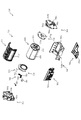
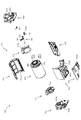
図3に示すように、パチンコ機10の背面側には、制御基板ユニット90,91と、裏パックユニット94とが主に備えられている。制御基板ユニット90は、主基板(主制御装置110)と音声ランプ制御基板(音声ランプ制御装置113)と表示制御基板(表示制御装置114)とが搭載されてユニット化されている。制御基板ユニット91は、払出制御基板(払出制御装置111)と発射制御基板(発射制御装置112)と電源基板(電源装置115)とカードユニット接続基板116とが搭載されてユニット化されている。   As shown in FIG. 3, control board units 90 and 91 and a back pack unit 94 are mainly provided on the back side of the pachinko machine 10. The control board unit 90 is unitized by mounting a main board (main control apparatus 110), an audio lamp control board (audio lamp control apparatus 113), and a display control board (display control apparatus 114). The control board unit 91 is unitized by mounting a payout control board (payout control apparatus 111), a firing control board (launching control apparatus 112), a power supply board (power supply apparatus 115), and a card unit connection board 116.

裏パックユニット94は、保護カバー部を形成する裏パック92と払出ユニット93とがユニット化されている。また、各制御基板には、各制御を司る1チップマイコンとしてのMPU、各種機器との連絡をとるポート、各種抽選の際に用いられる乱数発生器、時間計数や同期を図る場合などに使用されるクロックパルス発生回路等が、必要に応じて搭載されている。   The back pack unit 94 includes a back pack 92 and a dispensing unit 93 that form a protective cover. In addition, each control board is used for MPU as a one-chip microcomputer that controls each control, a port for communicating with various devices, a random number generator used for various lotteries, time counting and synchronization. A clock pulse generation circuit or the like is mounted as necessary.

なお、主制御装置110、音声ランプ制御装置113および表示制御装置114、払出制御装置111および発射制御装置112、電源装置115、カードユニット接続基板116は、それぞれ基板ボックス100〜104に収納されている。基板ボックス100〜104は、ボックスベースと該ボックスベースの開口部を覆うボックスカバーとを備えており、そのボックスベースとボックスカバーとが互いに連結されて、各制御装置や各基板が収納される。   The main control device 110, the sound lamp control device 113 and the display control device 114, the payout control device 111 and the firing control device 112, the power supply device 115, and the card unit connection board 116 are housed in the board boxes 100 to 104, respectively. . The board boxes 100 to 104 include a box base and a box cover that covers the opening of the box base. The box base and the box cover are connected to each other, and each control device and each board are accommodated.

また、基板ボックス100(主制御装置110)および基板ボックス102(払出制御装置111および発射制御装置112)は、ボックスベースとボックスカバーとを封印ユニット(図示せず)によって開封不能に連結(かしめ構造による連結)している。また、ボックスベースとボックスカバーとの連結部には、ボックスベースとボックスカバーとに亘って封印シール(図示せず)が貼着されている。この封印シールは、脆性な素材で構成されており、基板ボックス100,102を開封するために封印シールを剥がそうとしたり、基板ボックス100,102を無理に開封しようとすると、ボックスベース側とボックスカバー側とに切断される。よって、封印ユニット又は封印シールを確認することで、基板ボックス100,102が開封されたかどうかを知ることができる。   In addition, the substrate box 100 (main control device 110) and the substrate box 102 (dispensing control device 111 and launch control device 112) connect the box base and the box cover so that they cannot be opened by a sealing unit (not shown) (caulking structure). Consolidated). In addition, a seal (not shown) is attached to the connecting portion between the box base and the box cover so as to cover the box base and the box cover. This seal seal is made of a brittle material. If the seal is to be peeled off in order to open the substrate boxes 100, 102, or if the substrate boxes 100, 102 are forcibly opened, the box base side and the box cover are removed. Cut to the side. Therefore, it is possible to know whether or not the substrate boxes 100 and 102 have been opened by checking the sealing unit or the sealing seal.

払出ユニット93は、裏パックユニット94の最上部に位置して上方に開口したタンク130と、タンク130の下方に連結され下流側に向けて緩やかに傾斜するタンクレール131と、タンクレール131の下流側に縦向きに連結されるケースレール132と、ケースレール132の最下流部に設けられ、払出モータ216(図4参照)の所定の電気的構成により球の払出を行う払出装置133とを備えている。タンク130には、遊技ホールの島設備から供給される球が逐次補給され、払出装置133により必要個数の球の払い出しが適宜行われる。タンクレール131には、当該タンクレール131に振動を付加するためのバイブレータ134が取り付けられている。   The payout unit 93 includes a tank 130 that is located at the top of the back pack unit 94 and opens upward, a tank rail 131 that is connected to the lower side of the tank 130 and is gently inclined toward the downstream side, and downstream of the tank rail 131. A case rail 132 that is vertically connected to the side, and a payout device 133 that is provided at the most downstream portion of the case rail 132 and that pays out a ball by a predetermined electrical configuration of the payout motor 216 (see FIG. 4). ing. Balls supplied from the island facilities of the game hall are sequentially replenished to the tank 130, and a required number of balls are paid out by the payout device 133 as appropriate. A vibrator 134 for applying vibration to the tank rail 131 is attached to the tank rail 131.

また、払出制御装置111には状態復帰スイッチ120が設けられ、発射制御装置112には可変抵抗器の操作つまみ121が設けられ、電源装置115にはRAM消去スイッチ122が設けられている。状態復帰スイッチ120は、例えば、払出モータ216(図4参照)部の球詰まり等、払出エラーの発生時に球詰まりを解消(正常状態への復帰)するために操作される。操作つまみ121は、発射ソレノイドの発射力を調整するために操作される。RAM消去スイッチ122は、パチンコ機10を初期状態に戻したい場合に電源投入時に操作される。   The payout control device 111 is provided with a state return switch 120, the firing control device 112 is provided with a variable resistor operation knob 121, and the power supply device 115 is provided with a RAM erase switch 122. The state return switch 120 is operated, for example, to eliminate ball clogging (return to a normal state) when a payout error occurs, such as ball clogging in the payout motor 216 (see FIG. 4). The operation knob 121 is operated to adjust the firing force of the firing solenoid. The RAM erase switch 122 is operated when the power is turned on to return the pachinko machine 10 to the initial state.

次に、図4を参照して、本パチンコ機10の電気的構成について説明する。図4は、パチンコ機10の電気的構成を示すブロック図である。   Next, the electrical configuration of the pachinko machine 10 will be described with reference to FIG. FIG. 4 is a block diagram showing an electrical configuration of the pachinko machine 10.

主制御装置110には、演算装置である1チップマイコンとしてのMPU201が搭載されている。MPU201には、該MPU201により実行される各種の制御プログラムや固定値データを記憶したROM202と、そのROM202内に記憶される制御プログラムの実行に際して各種のデータ等を一時的に記憶するためのメモリであるRAM203と、そのほか、割込回路やタイマ回路、データ送受信回路などの各種回路が内蔵されている。主制御装置110では、MPU201によって、大当たり抽選や第1図柄表示装置37A,37Bおよび第3図柄表示装置81における表示の設定、第2図柄表示装置における表示結果の抽選といったパチンコ機10の主要な処理を実行する。   The main controller 110 is equipped with an MPU 201 as a one-chip microcomputer that is an arithmetic unit. The MPU 201 includes a ROM 202 that stores various control programs executed by the MPU 201 and fixed value data, and a memory that temporarily stores various data when the control program stored in the ROM 202 is executed. A certain RAM 203 and various other circuits such as an interrupt circuit, a timer circuit, and a data transmission / reception circuit are incorporated. In main controller 110, main processing of pachinko machine 10 such as jackpot lottery, setting of display on first symbol display devices 37A and 37B and third symbol display device 81, and lottery of display results on second symbol display device are performed by MPU 201. Execute.

なお、払出制御装置111や音声ランプ制御装置113などのサブ制御装置に対して動作を指示するために、主制御装置110から該サブ制御装置へ各種のコマンドがデータ送受信回路によって送信されるが、かかるコマンドは、主制御装置110からサブ制御装置へ一方向にのみ送信される。   Various commands are transmitted from the main control device 110 to the sub control device by the data transmission / reception circuit in order to instruct the sub control device such as the payout control device 111 and the sound lamp control device 113 to operate. Such a command is transmitted from the main controller 110 to the sub controller only in one direction.

RAM203は、各種エリア、カウンタ、フラグのほか、MPU201の内部レジスタの内容やMPU201により実行される制御プログラムの戻り先番地などが記憶されるスタックエリアと、各種のフラグおよびカウンタ、I/O等の値が記憶される作業エリア(作業領域)とを有している。なお、RAM203は、パチンコ機10の電源の遮断後においても電源装置115からバックアップ電圧が供給されてデータを保持(バックアップ)できる構成となっており、RAM203に記憶されるデータは、すべてバックアップされる。   The RAM 203 stores various areas, counters, flags, a stack area for storing the contents of the internal registers of the MPU 201 and a return address of a control program executed by the MPU 201, various flags, counters, I / O, and the like. And a work area (work area) in which values are stored. Note that the RAM 203 is configured so that the backup voltage is supplied from the power supply device 115 and the data can be retained (backed up) even after the power of the pachinko machine 10 is shut off, and all data stored in the RAM 203 is backed up. .

停電などの発生により電源が遮断されると、その電源遮断時(停電発生時を含む。以下同様)のスタックポインタや、各レジスタの値がRAM203に記憶される。一方、電源投入時(停電解消による電源投入を含む。以下同様)には、RAM203に記憶される情報に基づいて、パチンコ機10の状態が電源遮断前の状態に復帰される。RAM203への書き込みはメイン処理(図示せず)によって電源遮断時に実行され、RAM203に書き込まれた各値の復帰は電源投入時の立ち上げ処理(図示せず)において実行される。なお、MPU201のNMI端子(ノンマスカブル割込端子)には、停電等の発生による電源遮断時に、停電監視回路252からの停電信号SG1が入力されるように構成されており、その停電信号SG1がMPU201へ入力されると、停電時処理としてのNMI割込処理(図示せず)が即座に実行される。   When the power is shut down due to the occurrence of a power failure or the like, the stack pointer and the value of each register when the power is shut off (including when the power failure occurs, the same applies hereinafter) are stored in the RAM 203. On the other hand, at the time of power-on (including power-on due to power failure cancellation, the same applies hereinafter), the state of the pachinko machine 10 is restored to the state before power-off based on information stored in the RAM 203. Writing to the RAM 203 is executed when the power is shut off by a main process (not shown), and restoration of each value written to the RAM 203 is executed in a start-up process (not shown) when the power is turned on. Note that the power failure signal SG1 from the power failure monitoring circuit 252 is input to the NMI terminal (non-maskable interrupt terminal) of the MPU 201 when the power is interrupted due to the occurrence of a power failure or the like. Is input immediately, an NMI interrupt process (not shown) as a power failure process is immediately executed.

主制御装置110のMPU201には、アドレスバスおよびデータバスで構成されるバスライン204を介して入出力ポート205が接続されている。入出力ポート205には、払出制御装置111、音声ランプ制御装置113、第1図柄表示装置37A,37B、第2図柄表示装置、第2図柄保留ランプ、特定入賞口65aの開閉板の下辺を軸として前方側に開閉駆動するための大開放口ソレノイドや電動役物を駆動するためのソレノイドなどからなるソレノイド209が接続され、MPU201は、入出力ポート205を介してこれらに対し各種コマンドや制御信号を送信する。   An input / output port 205 is connected to the MPU 201 of the main control device 110 via a bus line 204 composed of an address bus and a data bus. The input / output port 205 has a payout control device 111, an audio lamp control device 113, first symbol display devices 37A and 37B, a second symbol display device, a second symbol holding lamp, and a lower side of the opening / closing plate of the specific winning opening 65a. A solenoid 209 made up of a large opening solenoid for opening and closing the front side and a solenoid for driving an electric accessory is connected to the MPU 201 via the input / output port 205. Send.

また、入出力ポート205には、図示しないスイッチ群およびスライド位置検出センサSや回転位置検出センサRを含むセンサ群などからなる各種スイッチ208、電源装置115に設けられた後述のRAM消去スイッチ回路253が接続され、MPU201は各種スイッチ208から出力される信号や、RAM消去スイッチ回路253より出力されるRAM消去信号SG2に基づいて各種処理を実行する。   The input / output port 205 includes a switch group (not shown), various switches 208 including a sensor group including a slide position detection sensor S and a rotation position detection sensor R, and a RAM erase switch circuit 253 described later provided in the power supply device 115. Are connected, and the MPU 201 executes various processes based on signals output from the various switches 208 and the RAM erase signal SG2 output from the RAM erase switch circuit 253.

払出制御装置111は、払出モータ216を駆動させて賞球や貸出球の払出制御を行うものである。演算装置であるMPU211は、そのMPU211により実行される制御プログラムや固定値データ等を記憶したROM212と、ワークメモリ等として使用されるRAM213とを有している。   The payout control device 111 drives the payout motor 216 to perform payout control of prize balls and rental balls. The MPU 211, which is an arithmetic unit, includes a ROM 212 that stores a control program executed by the MPU 211, fixed value data, and the like, and a RAM 213 that is used as a work memory or the like.

払出制御装置111のRAM213は、主制御装置110のRAM203と同様に、MPU211の内部レジスタの内容やMPU211により実行される制御プログラムの戻り先番地などが記憶されるスタックエリアと、各種のフラグおよびカウンタ、I/O等の値が記憶される作業エリア(作業領域)とを有している。RAM213は、パチンコ機10の電源の遮断後においても電源装置115からバックアップ電圧が供給されてデータを保持(バックアップ)できる構成となっており、RAM213に記憶されるデータは、すべてバックアップされる。なお、主制御装置110のMPU201と同様、MPU211のNMI端子にも、停電等の発生による電源遮断時に停電監視回路252から停電信号SG1が入力されるように構成されており、その停電信号SG1がMPU211へ入力されると、停電時処理としてのNMI割込処理(図示せず)が即座に実行される。   The RAM 213 of the payout control device 111, like the RAM 203 of the main control device 110, has a stack area for storing the contents of the internal registers of the MPU 211, the return address of the control program executed by the MPU 211, and various flags and counters. And a work area (work area) in which values such as I / O are stored. The RAM 213 is configured to be able to retain (backup) data by being supplied with a backup voltage from the power supply device 115 even after the power of the pachinko machine 10 is cut off, and all data stored in the RAM 213 is backed up. As with the MPU 201 of the main controller 110, the power failure signal SG1 is also input to the NMI terminal of the MPU 211 from the power failure monitoring circuit 252 when the power is interrupted due to the occurrence of a power failure or the like. When input to the MPU 211, an NMI interrupt process (not shown) as a power failure process is immediately executed.

払出制御装置111のMPU211には、アドレスバスおよびデータバスで構成されるバスライン214を介して入出力ポート215が接続されている。入出力ポート215には、主制御装置110や払出モータ216、発射制御装置112などがそれぞれ接続されている。また、図示はしないが、払出制御装置111には、払い出された賞球を検出するための賞球検出スイッチが接続されている。なお、該賞球検出スイッチは、払出制御装置111に接続されるが、主制御装置110には接続されていない。   An input / output port 215 is connected to the MPU 211 of the payout control device 111 via a bus line 214 composed of an address bus and a data bus. The main control device 110, the payout motor 216, the firing control device 112, and the like are connected to the input / output port 215, respectively. Although not shown, the payout control device 111 is connected to a prize ball detection switch for detecting a prize ball that has been paid out. The prize ball detection switch is connected to the payout control device 111 but is not connected to the main control device 110.

発射制御装置112は、主制御装置110により球の発射の指示がなされた場合に、操作ハンドル51の回動操作量に応じた球の打ち出し強さとなるよう球発射ユニット112aを制御するものである。球発射ユニット112aは、図示しない発射ソレノイドおよび電磁石を備えており、その発射ソレノイドおよび電磁石は、所定条件が整っている場合に駆動が許可される。具体的には、遊技者が操作ハンドル51に触れていることをタッチセンサ51aにより検出し、球の発射を停止させるための発射停止スイッチ51bがオフ(操作されていないこと)を条件に、操作ハンドル51の回動操作量(回動位置)に対応して発射ソレノイドが励磁され、操作ハンドル51の操作量に応じた強さで球が発射される。   The launch control device 112 controls the ball launch unit 112a so that the launch strength of the ball according to the rotation operation amount of the operation handle 51 is obtained when the main control device 110 gives an instruction to launch a ball. . The ball launching unit 112a includes a launching solenoid and an electromagnet (not shown), and the firing solenoid and the electromagnet are permitted to be driven when predetermined conditions are met. Specifically, the touch sensor 51a detects that the player is touching the operation handle 51, and the operation is performed on the condition that the launch stop switch 51b for stopping the launch of the ball is off (not operated). The firing solenoid is excited corresponding to the amount of rotation (rotation position) of the handle 51, and a ball is launched with a strength corresponding to the amount of operation of the operation handle 51.

音声ランプ制御装置113は、音声出力装置(図示しないスピーカなど)226における音声の出力、ランプ表示装置(電飾部29〜33、表示ランプ34など)227における点灯および消灯の出力、変動演出(変動表示)や予告演出といった表示制御装置114で行われる第3図柄表示装置81の表示態様の設定などを制御するものである。演算装置であるMPU221は、そのMPU221により実行される制御プログラムや固定値データ等を記憶したROM222と、ワークメモリ等として使用されるRAM223とを有している。   The sound lamp control device 113 outputs sound in a sound output device (such as a speaker (not shown)) 226, outputs lighting and extinguishing in a lamp display device (lighting units 29 to 33, display lamp 34, etc.) 227, and fluctuating effects (fluctuation). Display) and setting of the display mode of the third symbol display device 81 performed by the display control device 114 such as a notice effect. The MPU 221 that is an arithmetic unit includes a ROM 222 that stores a control program executed by the MPU 221, fixed value data, and the like, and a RAM 223 that is used as a work memory or the like.

音声ランプ制御装置113のMPU221には、アドレスバスおよびデータバスで構成されるバスライン224を介して入出力ポート225が接続されている。入出力ポート225には、主制御装置110、表示制御装置114、音声出力装置226、ランプ表示装置227、その他装置228、枠ボタン22などがそれぞれ接続されている。その他装置228には、駆動モータKM1,KM2,KM3が含まれる。   An input / output port 225 is connected to the MPU 221 of the sound lamp control device 113 via a bus line 224 including an address bus and a data bus. Main controller 110, display controller 114, audio output device 226, lamp display device 227, other device 228, frame button 22 and the like are connected to input / output port 225, respectively. Other devices 228 include drive motors KM1, KM2, and KM3.

音声ランプ制御装置113は、主制御装置110から受信した各種のコマンド(変動パターンコマンド、停止種別コマンド等)に基づいて、第3図柄表示装置81の表示態様を決定し、決定した表示態様をコマンド(表示用変動パターンコマンド、表示用停止種別コマンド等)によって表示制御装置114へ通知する。また、音声ランプ制御装置113は、枠ボタン22からの入力を監視し、遊技者によって枠ボタン22が操作された場合は、第3図柄表示装置81で表示されるステージを変更したり、スーパーリーチ時の演出内容を変更したりするように、表示制御装置114へ指示する。ステージが変更される場合は、変更後のステージに応じた背面画像を第3図柄表示装置81に表示させるべく、変更後のステージに関する情報を含めた背面画像変更コマンドを表示制御装置114へ送信する。ここで、背面画像とは、第3図柄表示装置81に表示させる主要な画像である第3図柄の背面側に表示される画像のことである。表示制御装置114は、この音声ランプ制御装置113から送信されるコマンドに従って、第3図柄表示装置81に各種の画像を表示する。   The sound lamp control device 113 determines the display mode of the third symbol display device 81 based on various commands (variation pattern command, stop type command, etc.) received from the main control device 110, and uses the determined display mode as a command. The display control device 114 is notified by (display variation pattern command, display stop type command, etc.). The sound lamp control device 113 monitors the input from the frame button 22, and when the player operates the frame button 22, the stage displayed on the third symbol display device 81 is changed, or the super reach is performed. The display control device 114 is instructed to change the production contents at the time. When the stage is changed, a rear image change command including information on the changed stage is transmitted to the display control device 114 so that the rear image corresponding to the changed stage is displayed on the third symbol display device 81. . Here, the back image is an image displayed on the back side of the third symbol, which is a main image displayed on the third symbol display device 81. The display control device 114 displays various images on the third symbol display device 81 according to the command transmitted from the sound lamp control device 113.

また、音声ランプ制御装置113は、表示制御装置114から第3図柄表示装置81の表示内容を表すコマンド(表示コマンド)を受信する。音声ランプ制御装置113では、表示制御装置114から受信した表示コマンドに基づき、第3図柄表示装置81の表示内容に合わせて、その表示内容に対応する音声を音声出力装置226から出力し、また、その表示内容に対応させてランプ表示装置227の点灯および消灯を制御する。   Further, the sound lamp control device 113 receives a command (display command) representing the display content of the third symbol display device 81 from the display control device 114. The voice lamp control device 113 outputs the voice corresponding to the display content from the voice output device 226 in accordance with the display content of the third symbol display device 81 based on the display command received from the display control device 114, The lighting and extinguishing of the lamp display device 227 are controlled in accordance with the display contents.

表示制御装置114は、音声ランプ制御装置113および第3図柄表示装置81が接続され、音声ランプ制御装置113より受信したコマンドに基づいて、第3図柄表示装置81における第3図柄の変動演出などの表示を制御するものである。また、表示制御装置114は、第3図柄表示装置81の表示内容を通知する表示コマンドを適宜音声ランプ制御装置113へ送信する。音声ランプ制御装置113は、この表示コマンドによって示される表示内容にあわせて音声出力装置226から音声を出力することで、第3図柄表示装置81の表示と音声出力装置226からの音声出力とをあわせることができる。   The display control device 114 is connected to the sound lamp control device 113 and the third symbol display device 81, and based on a command received from the sound lamp control device 113, the third symbol display device 81 has a variation effect of the third symbol, etc. The display is controlled. Further, the display control device 114 appropriately transmits a display command for notifying the display content of the third symbol display device 81 to the sound lamp control device 113. The voice lamp control device 113 outputs the voice from the voice output device 226 in accordance with the display content indicated by the display command, thereby matching the display of the third symbol display device 81 with the voice output from the voice output device 226. be able to.

電源装置115は、パチンコ機10の各部に電源を供給するための電源部251と、停電等による電源遮断を監視する停電監視回路252と、RAM消去スイッチ122(図3参照)が設けられたRAM消去スイッチ回路253とを有している。電源部251は、図示しない電源経路を通じて、各制御装置110〜114等に対して各々に必要な動作電圧を供給する装置である。その概要としては、電源部251は、外部より供給される交流24ボルトの電圧を取り込み、各種スイッチ208などの各種スイッチや、ソレノイド209などのソレノイド、モータ等を駆動するための12ボルトの電圧、ロジック用の5ボルトの電圧、RAMバックアップ用のバックアップ電圧などを生成し、これら12ボルトの電圧、5ボルトの電圧およびバックアップ電圧を各制御装置110〜114等に対して必要な電圧を供給する。   The power supply device 115 includes a power supply unit 251 for supplying power to each unit of the pachinko machine 10, a power failure monitoring circuit 252 for monitoring power interruption due to a power failure, and a RAM deletion switch 122 (see FIG. 3). And an erasing switch circuit 253. The power supply unit 251 is a device that supplies a necessary operating voltage to each of the control devices 110 to 114 through a power supply path (not shown). As its outline, the power supply unit 251 takes in the voltage of AC 24 volts supplied from the outside, and drives various switches such as various switches 208, solenoids such as the solenoid 209, motors, etc. A 5 volt voltage for logic, a backup voltage for RAM backup, and the like are generated, and the 12 volt voltage, the 5 volt voltage, and the backup voltage are supplied to the control devices 110 to 114 as necessary voltages.

停電監視回路252は、停電等の発生による電源遮断時に、主制御装置110のMPU201および払出制御装置111のMPU211の各NMI端子へ停電信号SG1を出力するための回路である。停電監視回路252は、電源部251から出力される最大電圧である直流安定24ボルトの電圧を監視し、この電圧が22ボルト未満になった場合に停電(電源断、電源遮断)の発生と判断して、停電信号SG1を主制御装置110および払出制御装置111へ出力する。停電信号SG1の出力によって、主制御装置110および払出制御装置111は、停電の発生を認識し、NMI割込処理を実行する。なお、電源部251は、直流安定24ボルトの電圧が22ボルト未満になった後においても、NMI割込処理の実行に充分な時間の間、制御系の駆動電圧である5ボルトの電圧の出力を正常値に維持するように構成されている。よって、主制御装置110および払出制御装置111は、NMI割込処理(図示せず)を正常に実行し完了することができる。   The power failure monitoring circuit 252 is a circuit for outputting a power failure signal SG1 to each NMI terminal of the MPU 201 of the main control device 110 and the MPU 211 of the payout control device 111 when the power is cut off due to the occurrence of a power failure or the like. The power failure monitoring circuit 252 monitors the DC stable voltage of 24 volts, which is the maximum voltage output from the power supply unit 251, and determines that a power failure (power interruption, power interruption) occurs when this voltage falls below 22 volts. Then, the power failure signal SG1 is output to the main controller 110 and the payout controller 111. Based on the output of the power failure signal SG1, the main control device 110 and the payout control device 111 recognize the occurrence of the power failure and execute the NMI interrupt process. Note that the power supply unit 251 outputs a voltage of 5 volts, which is a drive voltage of the control system, for a time sufficient to execute the NMI interrupt processing even after the DC stable voltage of 24 volts becomes less than 22 volts. Is maintained at a normal value. Therefore, main controller 110 and payout controller 111 can normally execute and complete the NMI interrupt process (not shown).

RAM消去スイッチ回路253は、RAM消去スイッチ122(図3参照)が押下された場合に、主制御装置110へ、バックアップデータをクリアさせるためのRAM消去信号SG2を出力するための回路である。主制御装置110は、パチンコ機10の電源投入時に、RAM消去信号SG2を入力した場合に、バックアップデータをクリアすると共に、払出制御装置111においてバックアップデータをクリアさせるための払出初期化コマンドを払出制御装置111に対して送信する。   The RAM erase switch circuit 253 is a circuit for outputting a RAM erase signal SG2 for clearing backup data to the main controller 110 when the RAM erase switch 122 (see FIG. 3) is pressed. When the RAM erase signal SG2 is input when the pachinko machine 10 is powered on, the main control device 110 clears the backup data, and the payout control device 111 issues a payout initialization command for clearing the backup data. Transmit to device 111.

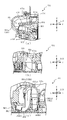
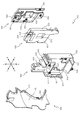
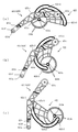
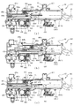
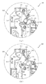
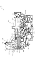
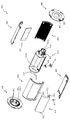
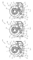
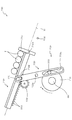
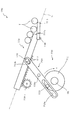
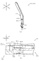
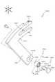
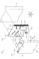
次いで、図5から図10を参照して、動作ユニット200の概略構成について説明する。図5は、パチンコ機10の分解斜視正面図であり、図6は、動作ユニット200及び遊技盤13の分解斜視正面図である。また、図7から図10は、動作ユニット200の正面図である。   Next, a schematic configuration of the operation unit 200 will be described with reference to FIGS. FIG. 5 is an exploded perspective front view of the pachinko machine 10, and FIG. 6 is an exploded perspective front view of the operation unit 200 and the game board 13. 7 to 10 are front views of the operation unit 200. FIG.

なお、図7では、上変位部材940が上方に退避されると共に、下変位部材440が下方に退避された状態が、図8では、図7に示す状態から、上変位部材940が下方に回転変位された状態が、図9では、図7に示す状態から、下変位部材440が後述する第1張出位置に張り出された状態が、図10では、下変位部材440が、最大の張り出し位置である第2張出位置に変位された状態が、それぞれ図示される。   In FIG. 7, the upper displacement member 940 is retracted upward and the lower displacement member 440 is retracted downward. In FIG. 8, the upper displacement member 940 rotates downward from the state shown in FIG. In FIG. 9, the displaced state is the state shown in FIG. 7, and the state in which the lower displacement member 440 is projected to a first projecting position to be described later is shown in FIG. 10. The state displaced to the 2nd overhang position which is a position is each illustrated.

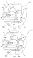
図5及び図6に示すように、動作ユニット200は、箱状に形成される背面ケース300を備え、その背面ケース300の内部空間に、上変位ユニット900、下変位ユニット400、回転ユニット700及び遊技盤13の背面に取着される振分けユニット5あ00と送球ユニット600とが収容される。   As shown in FIGS. 5 and 6, the operation unit 200 includes a rear case 300 formed in a box shape, and an upper displacement unit 900, a lower displacement unit 400, a rotation unit 700, and an inner space of the rear case 300. The distribution unit 5 00 and the pitching unit 600 attached to the back of the game board 13 are accommodated.

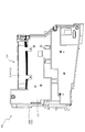
背面ケース300は、正面視略矩形の底壁部301と、その底壁部301の4辺の外縁から正面へ向けて立設される外壁部302とを備え、それら各壁部301,302により一面側(正面側)が開放された箱状に形成される。底壁部301には、その中央に正面視矩形の開口301aが開口形成され、その開口301aを通じて、底壁部301の背面に配設される第3図柄表示装置81(図2参照)が視認可能とされる。   The back case 300 includes a bottom wall 301 having a substantially rectangular shape when viewed from the front, and an outer wall 302 standing from the outer edges of the four sides of the bottom wall 301 toward the front. It is formed in a box shape with one side (front side) open. The bottom wall 301 is formed with an opening 301a having a rectangular shape when viewed from the front, and the third symbol display device 81 (see FIG. 2) disposed on the back of the bottom wall 301 is visually recognized through the opening 301a. It is possible.

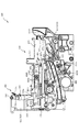
上変位ユニット900は、背面ケース300の底壁部301のうちの開口301aの上側部分に配設される正面視矩形横長のベース部材910と、そのベース部材910に摺動可能に配設される上変位部材940とを備え、背面ケース300の開口301a(即ち、第3図柄表示装置81)の正面側で、上変位部材940を摺動させつつ回転変位させる演出を実行可能に形成される。なお、上変位ユニット900の詳しい説明は後述する。   The upper displacement unit 900 is disposed in the upper part of the opening 301a in the bottom wall portion 301 of the back case 300, and has a rectangular horizontally long base member 910, and is slidably disposed on the base member 910. The upper displacement member 940 is provided, and an effect of rotating and displacing the upper displacement member 940 while sliding is formed on the front side of the opening 301a of the rear case 300 (that is, the third symbol display device 81). A detailed description of the upper displacement unit 900 will be given later.

下変位ユニット400は、背面ケース300の底壁部301のうちの開口301aの下側部分に配設される正面視矩形横長のベース部材410と、そのベース部材410に摺動可能に配設される下変位部材440とを備え、背面ケースの開口301a(即ち、第3図柄表示装置81)の正面側で、下変位部材440を摺動させつつ回転変位させる演出を実行可能に形成される。なお、下変位ユニット400の詳しい説明は後述する。   The lower displacement unit 400 is disposed in the bottom side of the bottom wall portion 301 of the back case 300 at a lower portion of the opening 301 a and has a horizontally long base member 410 in a front view, and is slidably disposed on the base member 410. The lower displacement member 440 is provided, and an effect of rotating and displacing the lower displacement member 440 while sliding is formed on the front side of the rear case opening 301a (ie, the third symbol display device 81). A detailed description of the lower displacement unit 400 will be described later.

回転ユニット700は、背面ケース300の底壁部301のうちの開口301aの下側部分の正面視右側(矢印)に配設される正面視略矩形の背面ベース720と、その背面ベース720の前方に配設される回転体800とを備え、遊技盤13の正面視右側下方に形成される透明の板部を介して回転体800を回転変位させる演出を遊技者に視認可能とされる。なお、回転ユニット700の詳細な説明については後述する。   The rotation unit 700 includes a rear base 720 having a substantially rectangular shape in front view disposed on the right side (arrow) in front view of the lower portion of the opening 301a in the bottom wall portion 301 of the rear case 300, and a front side of the rear base 720. And the player can visually recognize the effect of rotationally displacing the rotary body 800 through a transparent plate portion formed on the lower right side of the game board 13 when viewed from the front. The detailed description of the rotating unit 700 will be described later.

送球ユニット600は、遊技盤13の背面側に取着され、遊技盤13の第3入賞口82から遊技盤13の背面側に送球される遊技球を後述する振分けユニット500の第1開口511に送球する経路が形成される。   The ball sending unit 600 is attached to the back side of the game board 13 and a game ball sent from the third winning port 82 of the game board 13 to the back side of the game board 13 is input to a first opening 511 of the distribution unit 500 described later. A path for pitching is formed.

振分けユニット500は、遊技盤13の背面側に取着される経路形成部材510と、経路形成部材510との対向に所定の隙間を形成した状態で配設されるベース板520と、そのベース板520に取着され経路形成部材510とベース板520との対向間を流下する遊技球を各送球経路(第2送球経路KR2又は第3送球経路KR3)に振り分ける振分け部材540とを備える。この振分け部材540に振り分けられた遊技球が下変位ユニット400に送球される。なお、振分けユニット500の詳しい説明は後述する。   The distribution unit 500 includes a path forming member 510 attached to the back side of the game board 13, a base plate 520 disposed in a state where a predetermined gap is formed opposite the path forming member 510, and the base plate There is provided a sorting member 540 that distributes game balls that are attached to 520 and flow down between the path forming member 510 and the base plate 520 to each pitching path (second pitching path KR2 or third pitching path KR3). The game balls distributed to the distribution member 540 are sent to the lower displacement unit 400. A detailed description of the distribution unit 500 will be described later.

<第1の装飾体と第2の装飾体が前後方向に隣り合う位置に配置される>
次いで、図11から図16を参照して、遊技盤13に配設される一般入賞口ユニット150について説明する。
<A 1st decoration body and a 2nd decoration body are arrange|positioned in the position adjacent to the front-back direction>
Next, with reference to FIGS. 11 to 16, the general winning a prize opening unit 150 disposed on the game board 13 will be described.

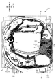
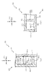
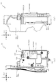
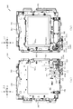
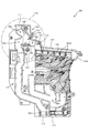
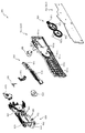
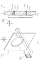
初めに、図11及び図12を参照して、一般入賞口ユニット150について説明する。図11は、遊技盤13の分解斜視正面図であり、図12(a)は、一般入賞口ユニット150の正面図であり、図12(b)は、図12(a)のXIIb−XIIb線における一般入賞口ユニット150の断面図である。   First, the general winning opening unit 150 will be described with reference to FIGS. 11 and 12. 11 is an exploded perspective front view of the game board 13, FIG. 12 (a) is a front view of the general winning opening unit 150, and FIG. 12 (b) is a line XIIb-XIIb in FIG. 12 (a). It is sectional drawing of the general winning opening unit 150 in.

図11及び図12に示すように、遊技盤13は、正面視略矩形状の板部材から形成されるベース板60と、そのベース板60に形成される開口部分に配設されるセンターフレーム86及び一般入賞口ユニット150と、を備える。   As shown in FIGS. 11 and 12, the game board 13 includes a base plate 60 formed from a plate member having a substantially rectangular shape when viewed from the front, and a center frame 86 disposed in an opening formed in the base plate 60. And a general prize opening unit 150.

ベース板60は、正面視において中央部分に開口される第1開口部60aと、レール部材76,77により形成される遊技領域の重力方向下側に開口される第2開口部60bと、を備える。第1開口部60aには、センターフレーム86が配設され、第2開口部60bには、一般入賞口ユニット150が配設される。また、ベース板60には、正面側(矢印F方向側)に装飾(模様や図柄等)が形成されたシールが貼付されて、遊技者にその装飾を視認させることができる。なお、ベース板60の正面側の装飾は、シールに限られるものではなく、ベース板60の正面に装飾が印刷(塗装)されるものであっても良い。   The base plate 60 includes a first opening 60a that is opened in the center portion when viewed from the front, and a second opening 60b that is opened on the lower side in the gravity direction of the game area formed by the rail members 76 and 77. . A center frame 86 is disposed in the first opening 60a, and a general prize opening unit 150 is disposed in the second opening 60b. In addition, a sticker with a decoration (pattern, symbol, etc.) formed on the front side (arrow F direction side) is attached to the base plate 60 so that the player can visually recognize the decoration. The decoration on the front side of the base plate 60 is not limited to the seal, and the decoration may be printed (painted) on the front surface of the base plate 60.

一般入賞口ユニット150は、遊技盤13の遊技領域(ベース板60の正面)に配設され、遊技領域を流下する遊技球の経路を変更可能とされる。また、一般入賞口ユニット150は、内レール76及び外レール77により囲われて形成される遊技領域に対して、正面視(矢印B方向視)における重力方向下側(矢印D方向側)の端部に沿う位置に配置される。なお、図13〜図16では、ベース板60に配設されるシールが装飾部材60cの符号を付して図示される。また、本実施形態では、装飾部材60cにキャラクター(人)が描かれる。   The general winning a prize opening unit 150 is disposed in the game area of the game board 13 (in front of the base plate 60), and the path of the game ball flowing down the game area can be changed. Further, the general winning a prize opening unit 150 has an end on the lower side in the gravitational direction (arrow D direction side) in the front view (viewed in the arrow B direction) with respect to the game area formed by being surrounded by the inner rail 76 and the outer rail 77. It is arranged at a position along the part. In FIGS. 13 to 16, the seal disposed on the base plate 60 is illustrated with the reference numeral of the decorative member 60 c. In the present embodiment, a character (person) is drawn on the decorative member 60c.

一般入賞口ユニット150は、正面視において三日月状に形成される本体部151と、その本体部151の端部から正面側(矢印F方向側)に立設される第1立設部152と、その第1立設部152の重力方向上側(矢印U方向側)の端部から遊技領域の中央側に向かって延設される第2立設部153と、本体部151の背面側に配設される装飾部材154と、本体部151の正面側に形成される複数(本実施形態では3個)の一般入賞口63と、を主に備える。   The general winning opening unit 150 includes a main body 151 formed in a crescent shape when viewed from the front, a first standing part 152 erected from the end of the main body 151 on the front side (arrow F direction side), A second standing portion 153 that extends from the end of the first standing portion 152 on the upper side in the gravity direction (arrow U direction side) toward the center of the game area, and a rear side of the main body portion 151. And a plurality of (three in this embodiment) general winning openings 63 formed mainly on the front side of the main body 151.

本体部151は、ベース板60の板厚方向に開口される第2開口部60bの開口形状よりも若干大きい外形に設定され、第2開口部60bの開口に覆設された状態でベース板60の正面側に配設される。また、第2開口部60bにより、本体部151に配設される一般入賞口63に流入する遊技球を遊技盤13(ベース板60)の背面側に送球できる。さらに、本体部151は、正面視において内側部分から外側の端部に向かうほどベース板60側に傾斜する傾斜面151aと、ベース板60側(矢印B方向側)の背面に凹設される凹部151bと、その凹部151bを除いた本体部151の背面を形成する背面部151dと、を主に備えて形成される。   The main body 151 is set to have an outer shape slightly larger than the opening shape of the second opening 60b opened in the thickness direction of the base plate 60, and is covered with the opening of the second opening 60b. It is arrange | positioned at the front side. Further, the second opening 60b allows the game ball flowing into the general winning opening 63 provided in the main body 151 to be sent to the back side of the game board 13 (base plate 60). Furthermore, the main body 151 includes an inclined surface 151a that inclines toward the base plate 60 as it goes from the inner portion to the outer end in a front view, and a recess that is recessed in the back surface on the base plate 60 side (arrow B direction side). 151 b and a back surface portion 151 d that forms the back surface of the main body portion 151 excluding the concave portion 151 b are mainly provided.

傾斜面151aは、ベース板60の正面に対して略30度ほど傾斜して形成される。これにより、遊技盤13の遊技領域を流下する遊技球を、傾斜面151aに当接させて傾斜面151aの傾斜に沿って流下させて、本体部151の正面側に移動させることができる。   The inclined surface 151 a is formed to be inclined by approximately 30 degrees with respect to the front surface of the base plate 60. Thereby, the game ball flowing down the game area of the game board 13 can be brought into contact with the inclined surface 151a and flow down along the inclination of the inclined surface 151a, and moved to the front side of the main body 151.

ここで、本体部151の端部に傾斜面151aが形成されず、本体部151の側面が、ベース板60の正面に対して垂直に形成される場合には、遊技盤13の遊技領域を流下する遊技球が、本体部151の側面に対して直交する方向から当接(衝突)して、その当接した遊技球が流下方向と反対方向に跳ね返る恐れがある。   Here, when the inclined surface 151 a is not formed at the end of the main body 151 and the side surface of the main body 151 is formed perpendicular to the front surface of the base plate 60, the game area of the game board 13 flows down. There is a possibility that the game ball to be abutted (collised) from the direction orthogonal to the side surface of the main body 151 and the abutted game ball rebounds in the direction opposite to the flow-down direction.

これに対し、本実施形態では、傾斜面151aにより、本体部151の側面に当接する遊技球を本体部の正面側に移動させることができるので、遊技領域を流下する遊技球の流下が一時的に停滞することを抑制できる。その結果、ベース板60の正面側から一般入賞口ユニット150の本体部151の正面に遊技球をスムーズに流下させることができる。   On the other hand, in this embodiment, the game ball that contacts the side surface of the main body portion 151 can be moved to the front side of the main body portion by the inclined surface 151a, so that the flow of the game ball flowing down the game area is temporarily It is possible to suppress stagnation. As a result, the game ball can flow smoothly from the front side of the base plate 60 to the front surface of the main body 151 of the general prize opening unit 150.

背面部151dは、上述したように本体部151の背面であり、背面視における凹部151bの周囲に一定の幅で形成される。また、背面部151dは、一般入賞口ユニット150がベース板60に配設された状態において、ベース板60(装飾部材60c)の正面に当接して配設される。   As described above, the back surface portion 151d is the back surface of the main body portion 151, and is formed with a certain width around the recess portion 151b in the rear view. Further, the back surface portion 151d is disposed in contact with the front surface of the base plate 60 (decorative member 60c) in a state where the general winning a prize opening unit 150 is disposed on the base plate 60.

凹部151bは、正面側(矢印F方向側)に向かって凹設される。また、凹部151bは、凹設方向の底面となる凹設底面151b2と、その凹設底面151b2の外縁から背面側(矢印B方向側)に向かって立設される内側面151b3と、を有する。   The recess 151b is recessed toward the front side (arrow F direction side). The concave portion 151b has a concave bottom surface 151b2 that is a bottom surface in the concave direction, and an inner side surface 151b3 that is erected from the outer edge of the concave bottom surface 151b2 toward the back side (arrow B direction side).

凹設底面151b2は、後述する装飾部材154の接着面であり、本体部151の正面と平行な平面として形成される。これにより、本体部151を介して装飾部材154の装飾を視認した場合に、装飾部材154の装飾を一様に視認させることができる。   The concave bottom surface 151b2 is an adhesive surface of a decorative member 154 described later, and is formed as a plane parallel to the front surface of the main body 151. Thereby, when the decoration of the decoration member 154 is visually recognized via the main body 151, the decoration of the decoration member 154 can be visually recognized uniformly.

内側面151b3は、正面視における前後方向(矢印F−B方向)に延設される。また、内側面151b3の正面視における形状は、後述する装飾部材154の外形と略同一に形成される。これにより、凹部151bに装飾部材154を配設した場合に、装飾部材154が凹部151bの外側に突出することを抑制できる。従って、一般入賞口ユニット150が、ベース板60に配設された際に、背面部151dとベース板60との間に装飾部材154が挟まることで本体部151の背面部151dとベース板60との間に隙間が形成されることを抑制できる。これにより、本体部151がベース板60に対して、通常の配設位置よりも正面側に張り出すことを抑制できる。その結果、ベース板60の正面側から一般入賞口ユニット150の本体部151の正面に遊技球をスムーズに流下させることができる。   Inner side surface 151b3 is extended in the front-back direction (arrow FB direction) in front view. Further, the shape of the inner side surface 151b3 in a front view is formed to be substantially the same as the outer shape of a decorative member 154 described later. Thereby, when the decorative member 154 is disposed in the concave portion 151b, the decorative member 154 can be prevented from protruding outside the concave portion 151b. Therefore, when the general winning a prize opening unit 150 is disposed on the base plate 60, the decoration member 154 is sandwiched between the back surface portion 151 d and the base plate 60, so that the back surface portion 151 d and the base plate 60 of the main body portion 151 are sandwiched. It is possible to suppress the formation of a gap between the two. Thereby, it can suppress that the main-body part 151 projects over the front side rather than the normal arrangement | positioning position with respect to the base board 60. FIG. As a result, the game ball can flow smoothly from the front side of the base plate 60 to the front surface of the main body 151 of the general prize opening unit 150.

凹部151bは、その凹設空間に後述する装飾部材154を収容する凹みであり、凹設深さ(正面側(矢印F方向側)への凹設距離)が、装飾部材154の厚み寸法よりも大きく設定される。また、凹部151bは、正面視における本体部151の端部から本体部151の内側に一定の距離を隔てた位置で本体部151の端部の形状に沿って凹設される。   The recess 151b is a recess that accommodates a decoration member 154, which will be described later, in the recess space, and the recess installation depth (recessed distance to the front side (arrow F direction side)) is larger than the thickness dimension of the decoration member 154. It is set large. The recess 151b is recessed along the shape of the end of the main body 151 at a position spaced a certain distance from the end of the main body 151 in the front view to the inside of the main body 151.

よって、凹部151bの内側に装飾部材154を配設した場合に、装飾部材154の背面が、本体部151よりも背面側に張り出すことを抑制できる。従って、一般入賞口ユニット150がベース板60に配設された際に、凹設底面151b2とベース板60との間に装飾部材154が挟まることで本体部151の背面部151dとベース板60との間に隙間が形成されることを抑制できる。これにより、本体部151がベース板60に対して通常の配設位置よりも正面側に張り出すことを抑制できる。その結果、本体部151の重力方向上方(矢印U方向)から一般入賞口ユニット150の本体部151の正面に遊技球をスムーズに流下させることができる。   Therefore, when the decorative member 154 is disposed inside the recess 151b, it is possible to suppress the back surface of the decorative member 154 from projecting to the back side of the main body portion 151. Therefore, when the general winning a prize opening unit 150 is disposed on the base plate 60, the decoration member 154 is sandwiched between the recessed bottom surface 151 b 2 and the base plate 60, so that the back surface portion 151 d of the main body portion 151 and the base plate 60 It is possible to suppress the formation of a gap between the two. Thereby, it can suppress that the main-body part 151 projects over the front side rather than the normal arrangement position with respect to the base board 60. FIG. As a result, the game ball can smoothly flow down from the upper side of the main body 151 in the direction of gravity (in the direction of the arrow U) to the front of the main body 151 of the general prize opening unit 150.

第1立設部152は、遊技領域の端部側(内レール76側)における本体部151の端部から正面側(矢印F方向側)に立設される。第1立設部152は、その立設寸法がベース板60(装飾部材60c)の正面に植立される内レール76の植立方向の幅寸法と略同一に設定される。また、第1立設部152は、遊技盤13の正面側を覆う前扉5のガラスユニット16との対向間の間隔が遊技球の直径よりも小さく設定される。これにより、本体部151の正面側を流下する遊技球を、遊技領域の重力方向下側の端部で第1立設部152に衝突させることができる。その結果、本体部151の正面側を流下する遊技球が内レール76に衝突することを抑制でき、内レール76が遊技球と衝突して曲げられることを抑制できる。   The first standing portion 152 is erected on the front side (arrow F direction side) from the end portion of the main body portion 151 on the end portion side (inner rail 76 side) of the game area. The first standing portion 152 is set to have the standing dimension substantially the same as the width dimension in the planting direction of the inner rail 76 planted on the front surface of the base plate 60 (decorative member 60c). Further, in the first standing portion 152, the distance between the front door 5 that covers the front side of the game board 13 and the glass unit 16 is set to be smaller than the diameter of the game ball. Thereby, the game ball flowing down the front side of the main body 151 can be made to collide with the first standing portion 152 at the lower end of the game area in the direction of gravity. As a result, it is possible to suppress the game ball flowing down the front side of the main body 151 from colliding with the inner rail 76, and to suppress the inner rail 76 from colliding with the game ball and being bent.

ここで、内レール76と外レール77との対向間は、球発射ユニット112a(図4参照)から発射された遊技球を遊技盤13の上部へ案内するための空間であり、内レール76と外レール77との対向間に補強等を配設するスペースが限られる。そのため、内レール76が曲がることを防止する目的で補強を配設することが困難であり、遊技領域を流下する遊技球が内レール76に衝突して、内レール76が曲がる恐れがあった。   Here, the space between the inner rail 76 and the outer rail 77 is a space for guiding the game ball launched from the ball launch unit 112a (see FIG. 4) to the upper part of the game board 13, A space for providing reinforcement or the like between the outer rail 77 and the outer rail 77 is limited. Therefore, it is difficult to arrange reinforcement for the purpose of preventing the inner rail 76 from bending, and there is a possibility that the game ball flowing down the game area collides with the inner rail 76 and the inner rail 76 is bent.

これに対して、本実施形態では、遊技領域内に配設される一般入賞口ユニット150(第1立設部152)により遊技領域を流下する遊技球が内レール76に衝突しにくくすることができる。従って、内レール76が曲ることで、内レール76及び外レール77の対向間の距離が変更されることを抑制できる。その結果、遊技球を安定して遊技領域に打ち出すことができる。   On the other hand, in the present embodiment, it is possible to make it difficult for a game ball flowing down the game area to collide with the inner rail 76 by the general prize opening unit 150 (first standing portion 152) disposed in the game area. it can. Therefore, it is possible to suppress a change in the distance between the facing of the inner rail 76 and the outer rail 77 due to the bending of the inner rail 76. As a result, the game ball can be stably launched into the game area.

第2立設部153は、正面視において第1立設部152の重力方向上側(矢印U方向側)の端部から遊技領域の中央(第1入賞口64)に向かって下降傾斜して延設される(図2参照)。これにより、内レール76とセンターフレーム83との対向間(図2参照)を流下する遊技球が、第2立設部153の下降傾斜する延設部分の上面(矢印U方向側の面)に送球されると、その遊技球を第2立設部153の下降傾斜に沿って転動させて、遊技領域の中央に向けて送球することができる。これにより、内レール76と外レール77との対向間側(矢印L方向側)の遊技領域を流下する遊技球を、遊技領域の中央に配設される第1入賞口64に入賞(流入)させやすくできる。   The second standing portion 153 extends downwardly from the end of the first standing portion 152 in the gravity direction (arrow U direction side) toward the center of the game area (first winning port 64) in front view. (See FIG. 2). Thereby, the game ball flowing down between the inner rail 76 and the center frame 83 (see FIG. 2) is placed on the upper surface (the surface on the arrow U direction side) of the extending portion of the second standing portion 153 that is inclined downward. When the ball is sent, the game ball can roll along the descending slope of the second standing portion 153 and can be sent toward the center of the game area. As a result, the game balls flowing down the game area on the opposite side (arrow L direction side) of the inner rail 76 and the outer rail 77 are won (inflow) into the first winning port 64 disposed in the center of the game area. It can be made easy.

装飾部材154は、板状に形成されると共に、本体部151の背面側に接着される。また、装飾部材154は、本体部151側の正面にベース板60の装飾部材60cに形成される装飾と正面視において連なる装飾が形成される。これにより、ベース板60に形成される装飾を装飾部材154の装飾と合わせて1の装飾に視認させることができる。なお、本実施形態では、装飾部材154にキャラクター(人)の一部が描かれており、装飾部材60cのキャラクターと装飾部材154のキャラクターとを合わせて1人のキャラクターとして視認させることができる。   The decorative member 154 is formed in a plate shape and is bonded to the back side of the main body 151. In addition, the decoration member 154 is provided with a decoration that is continuous with the decoration formed on the decoration member 60c of the base plate 60 in front view on the main body 151 side. Thereby, the decoration formed on the base plate 60 can be visually recognized as one decoration together with the decoration of the decoration member 154. In the present embodiment, a part of the character (person) is drawn on the decorative member 154, and the character of the decorative member 60c and the character of the decorative member 154 can be viewed together as one character.

また、装飾部材154は、光透過性材料から形成される。これにより、ベース板60の背面側(矢印B方向側)から第2開口部60bを通した光を装飾部材154の背面から入射させて、装飾部材154の正面側(矢印F方向側)から出射させることができる。よって、装飾部材154の正面に形成される装飾を明るくして、遊技者に視認させることができ、遊技者に装飾部材154の装飾を視認させやすくできる。   The decorative member 154 is made of a light transmissive material. Thereby, the light which passed through the 2nd opening part 60b from the back side (arrow B direction side) of the base board 60 enters from the back surface of the decoration member 154, and is radiate | emitted from the front side (arrow F direction side) of the decoration member 154. Can be made. Therefore, the decoration formed on the front surface of the decoration member 154 can be brightened and made visible to the player, and the player can easily make the decoration of the decoration member 154 visible.

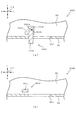
次いで、図13を参照して、ベース板60と一般入賞口ユニット150とについて説明する。図13は、図2のXIII−XIII線における遊技盤13の断面図である。   Next, the base plate 60 and the general winning opening unit 150 will be described with reference to FIG. 13 is a cross-sectional view of the game board 13 taken along line XIII-XIII in FIG.

図13に示すように、装飾部材154は、ベース板60の第2開口部60bの正面視における開口形状よりも外形が大きく形成される。これにより、一般入賞口ユニット150がベース板60に配設されると、装飾部材154の端部は、本体部151の凹部151bの凹設底面151b2とベース板60(装飾部材60c)との間に配置される。よって、本体部151と装飾部材154との接着が経年劣化等により剥がれた場合に、装飾部材154が遊技盤13から脱落することを抑制できる。   As shown in FIG. 13, the decorative member 154 has an outer shape larger than the opening shape of the second opening 60 b of the base plate 60 in a front view. Thus, when the general winning a prize opening unit 150 is disposed on the base plate 60, the end of the decorative member 154 is located between the concave bottom surface 151b2 of the concave portion 151b of the main body 151 and the base plate 60 (decorative member 60c). Placed in. Therefore, it is possible to prevent the decorative member 154 from dropping from the game board 13 when the adhesion between the main body 151 and the decorative member 154 is peeled off due to deterioration over time.

また、装飾部材154は、ベース板60と前後方向(矢印F−B方向)において重なる幅寸法が、後述する本体部151の背面から突設される突起155が挿入されるベース板60の円形状の開口60g(図11参照)の直径よりも大きく設定される。これにより、装飾部材154の本体部151に対する配置の位置ずれ、又は、装飾部材60cを形成した位置のずれにより、正面視における装飾部材154及び装飾部材60cの装飾の間に隙間が形成されることを抑制できる。その結果、ベース板60の装飾部材60cと装飾部材154の装飾とを1の装飾として遊技者に認識させやすくできる。   Further, the decorative member 154 has a width dimension that overlaps with the base plate 60 in the front-rear direction (arrow F-B direction), and the circular shape of the base plate 60 into which a protrusion 155 that protrudes from the back surface of the main body 151 described later is inserted. Is set larger than the diameter of the opening 60g (see FIG. 11). Thereby, a gap is formed between the decoration of the decoration member 154 and the decoration member 60c in the front view due to the displacement of the arrangement of the decoration member 154 with respect to the main body 151 or the position of the decoration member 60c. Can be suppressed. As a result, the player can easily recognize the decoration member 60c of the base plate 60 and the decoration of the decoration member 154 as one decoration.

また、本体部151に配設される3個の一般入賞口63は、遊技盤13の背面側に配設される振り分けユニット500(図71参照)の開口514〜516に接続されており、一般入賞口63に入賞した遊技球は、振り分けユニット500の第4送球経路KR4に送球される。なお、振り分けユニット500についての詳しい説明は後述する。   Further, the three general winning ports 63 arranged in the main body 151 are connected to the openings 514 to 516 of the distribution unit 500 (see FIG. 71) arranged on the back side of the game board 13. The game balls that have won the winning opening 63 are sent to the fourth pitch route KR4 of the sorting unit 500. A detailed description of the distribution unit 500 will be described later.

さらに、振り分けユニット500には、正面側に光を照射可能な光源を備える基板(図示しない)がベース板520(図71参照)に配設されており、その基板から照射される光がベース板60の第2開口部60bを挿通して一般入賞口ユニット150の背面に照射される。   Further, in the sorting unit 500, a substrate (not shown) having a light source capable of irradiating light on the front side is disposed on the base plate 520 (see FIG. 71), and the light emitted from the substrate is the base plate. The second opening 60b of 60 is inserted to irradiate the back of the general winning a prize opening unit 150.

よって、第2開口部60bは、一般入賞口ユニット150の一般入賞口63から入賞する遊技球の経路および一般入賞口ユニット150の背面に光を照射する空間として利用される。これにより、遊技球を送球するための開口と、光を通過させるための開口と、2箇所の開口を分けて形成する必要がなくなるので、一般入賞口ユニット150の背面の全域に光を照射しやすくすることができると共に、一般入賞口ユニット150の本体部151の全域に一般入賞口63を配置することができる。その結果、一般入賞口ユニット150の設計の自由度を向上することができると共に、一般入賞口ユニット150の全域から光を出射して一般入賞口ユニット150の装飾(装飾部材154)を遊技者に視認させやすくできる。   Therefore, the second opening 60 b is used as a space for irradiating light to the path of the game ball to be won from the general winning opening 63 of the general winning opening unit 150 and the back of the general winning opening unit 150. As a result, there is no need to separately form an opening for sending a game ball, an opening for allowing light to pass through, and two openings, so light is applied to the entire back surface of the general winning a prize opening unit 150. The general winning opening 63 can be arranged over the entire area of the main body 151 of the general winning opening unit 150. As a result, the degree of freedom in designing the general winning a prize opening unit 150 can be improved, and light is emitted from the entire area of the general winning a prize opening unit 150 to decorate the general winning a prize opening unit 150 (decorative member 154) to the player. Easy to see.

また、本実施形態によれば、図13に示すように、遊技盤13のベース板60の装飾部材60cと連なる装飾の装飾部材154は、ベース板60の正面に沿って配設される本体部151の背面に配置されるので、ベース板60の装飾部材60cと装飾部材154の装飾とを前後方向(矢印F−B方向)に隣合う(近づいた)位置に配置することができる。これにより、装飾部材60c及び装飾部材154の正面視に対して傾斜した角度(例えば、パチンコ機10(図1参照)の重力方向上側端部と同じ高さの視点)から装飾部材60c及び装飾部材154を視認した際に、一般入賞口ユニットの装飾が一般入賞口ユニットの正面に配設される場合に比べて、装飾部材60c及び装飾部材154の装飾がずれて視認されることを抑制できる。その結果、ベース板60の装飾部材60cと装飾部材154の装飾との連結部分を遊技者の視点に関わらず同様の位置関係で遊技者に視認させることができ、遊技盤13の意匠性を向上できる。   Further, according to the present embodiment, as shown in FIG. 13, the decorative member 154 that is connected to the decorative member 60 c of the base plate 60 of the game board 13 is disposed along the front surface of the base plate 60. Therefore, the decoration member 60c of the base plate 60 and the decoration of the decoration member 154 can be arranged at positions adjacent (approaching) in the front-rear direction (arrow FB direction). Accordingly, the decorative member 60c and the decorative member are viewed from an angle inclined with respect to the front view of the decorative member 60c and the decorative member 154 (for example, a viewpoint having the same height as the upper end portion in the gravity direction of the pachinko machine 10 (see FIG. 1)). It is possible to suppress the decoration of the decoration member 60c and the decoration member 154 from being visually recognized when the 154 is visually recognized, as compared with the case where the decoration of the general prize opening unit is disposed in front of the general prize opening unit. As a result, the connecting portion between the decoration member 60c of the base plate 60 and the decoration of the decoration member 154 can be viewed by the player in the same positional relationship regardless of the player's viewpoint, and the design of the game board 13 is improved. it can.

次いで、図14を参照して、装飾部材154及びベース板60の装飾部材60cの連結について詳しく説明する。図14は、図13の範囲XIVにおける遊技盤13の部分拡大断面図である。なお、図14では、遊技者に視認される光の経路が2点鎖線で図示される。   Next, the connection of the decorative member 154 and the decorative member 60c of the base plate 60 will be described in detail with reference to FIG. FIG. 14 is a partially enlarged cross-sectional view of the game board 13 in the range XIV of FIG. In FIG. 14, the light path visually recognized by the player is shown by a two-dot chain line.

上述したように、ベース板60の装飾部材60cと装飾部材154の装飾とは、合わせて1の装飾として遊技者に視認される。従って、ベース板60の装飾部材60cと装飾部材154の装飾とを1の装飾(模様)として遊技者に視認させるために、両者の装飾の位置ずれを抑える必要がある。しかしながら、ベース板60に装飾を形成する際、又は、本体部151に装飾部材154を配設する際に、その装飾を正確な位置(毎回同じ位置)に配置することが困難である。従って、ベース板60に一般入賞口ユニット150を配設した場合に、ベース板60の装飾部材60cに対する装飾部材154の装飾の位置がずれて配設されることで、装飾部材60cと装飾部材154との装飾を合わせて1の装飾として遊技者に視認させにくくなるという問題点があった。   As described above, the decoration member 60c of the base plate 60 and the decoration of the decoration member 154 are visually recognized by the player as one decoration. Therefore, in order for the player to visually recognize the decoration member 60c of the base plate 60 and the decoration of the decoration member 154 as one decoration (pattern), it is necessary to suppress the misalignment between the decorations of the two. However, when the decoration is formed on the base plate 60 or when the decoration member 154 is disposed on the main body 151, it is difficult to arrange the decoration at an accurate position (the same position every time). Accordingly, when the general winning a prize opening unit 150 is disposed on the base plate 60, the decoration position of the decoration member 154 with respect to the decoration member 60c of the base plate 60 is displaced so that the decoration member 60c and the decoration member 154 are disposed. In addition, there is a problem that it is difficult for the player to visually recognize the decoration as one decoration.

これに対して、本実施形態によれば、装飾部材154は、その端部が傾斜面151aの背面側に配置される。これにより、装飾部材154の装飾とベース板60の装飾部材60cの装飾との連結部分が、遊技者から正確に認識されにくくする(連結部分をぼやかして遊技者に視認させる)ことができる。よって、装飾部材60cと装飾部材154とを1の装飾として遊技者に認識させることができる。   On the other hand, according to this embodiment, the end of the decorative member 154 is disposed on the back side of the inclined surface 151a. Thereby, the connection part of the decoration of the decoration member 154 and the decoration of the decoration member 60c of the base plate 60 can be made difficult to be accurately recognized by the player (the connection part is blurred to make the player visually recognize). Therefore, the player can recognize the decoration member 60c and the decoration member 154 as one decoration.

詳しく説明すると、図14に示すように、装飾部材154の装飾と装飾部材60cの装飾との連結部(以下、「境界P1」(図14参照)と称す)は、本体部151の傾斜面151aの背面側に位置される。よって、境界P1から遊技者の視点に向かって出射される光と、本体部151の正面と傾斜面151aとの連結部(以下、「境界P2」(図14参照)と称す)から遊技者の視点に向かって出射される光とを、装飾部材60c又は装飾部材154の異なる位置で反射した光にすることができる(即ち、境界P1から遊技者の視点に向かって出射される光の経路上に、境界P2が形成されることを抑制できる)。   More specifically, as shown in FIG. 14, the connecting portion (hereinafter referred to as “boundary P1” (see FIG. 14)) of the decoration of the decoration member 154 and the decoration of the decoration member 60c is an inclined surface 151a of the main body 151. Located on the back side. Therefore, the light emitted from the boundary P1 toward the player's viewpoint and the connecting portion between the front surface of the main body 151 and the inclined surface 151a (hereinafter referred to as “boundary P2” (see FIG. 14)) The light emitted toward the viewpoint can be changed to light reflected at different positions of the decoration member 60c or the decoration member 154 (that is, on the path of the light emitted from the boundary P1 toward the player's viewpoint). In addition, the formation of the boundary P2 can be suppressed).

従って、境界P1では、装飾部材154に対する装飾部材60cの配置のずれが装飾の位置ずれとして遊技者に認識されやすく、又、境界P2では、光の屈折方向の違いによる装飾の位置ずれが遊技者に認識されやすいところ、境界P1及び境界P2のそれぞれの位置から遊技者が視認する装飾を異なる位置の装飾にすることができるので、境界P1及び境界P2における装飾の位置ずれが、同一の位置で遊技者に視認されることを抑制できる。従って、境界P1における装飾の位置ずれと、境界P2における装飾の位置ずれとが合わさり、装飾の位置ずれ量が大きくなって遊技者に認識されることを抑制できる。その結果、装飾部材60cと装飾部材154との装飾を遊技者に1の装飾として認識させやすくでき、遊技盤13の意匠性を向上できる。   Accordingly, at the boundary P1, the player can easily recognize the displacement of the decoration member 60c relative to the decoration member 154 as the displacement of the decoration, and at the boundary P2, the displacement of the decoration due to the difference in the light refraction direction is recognized by the player. Since the decoration visually recognized by the player from the respective positions of the boundary P1 and the boundary P2 can be made a decoration at different positions, the positional deviation of the decorations at the boundary P1 and the boundary P2 is the same position. Visible to the player can be suppressed. Therefore, it is possible to prevent the decoration position shift at the boundary P1 and the decoration position shift at the boundary P2 from being combined, and the amount of the decoration position shift is increased and recognized by the player. As a result, the decoration of the decoration member 60c and the decoration member 154 can be easily recognized by the player as one decoration, and the design of the game board 13 can be improved.

さらに、境界P1を傾斜面151aの背面側に配置することで、遊技者の視点において、装飾部材60c及び本体部151の連結部(以下、「境界P3」(図14参照)と称す)と、境界P2との間に境界P1を配置することができる。よって、本体部151から光が出射する際に光が屈折することによる装飾の位置ずれ位置(境界P2,P3)の間に、境界P1を配置することができる。従って、装飾の位置がずれて認識される領域が間延びすることを抑制できる。即ち、装飾の位置がずれて視認される領域を遊技盤13の正面に対して限定的にすることができる。その結果、装飾の位置ずれ領域を遊技盤13の遊技領域に対して、少なくすることができるので、装飾部材60c及び装飾部材154の装飾を遊技者に1の装飾として認識させやすくできる。   Furthermore, by arranging the boundary P1 on the back side of the inclined surface 151a, from the viewpoint of the player, a connecting portion of the decorative member 60c and the main body 151 (hereinafter referred to as “boundary P3” (see FIG. 14)), The boundary P1 can be arranged between the boundary P2. Therefore, the boundary P1 can be disposed between the position positions (decreases P2 and P3) of the decoration due to the light being refracted when the light is emitted from the main body 151. Therefore, it is possible to suppress the extension of the recognized area by shifting the decoration position. That is, it is possible to limit the area where the position of the decoration is visually recognized with respect to the front of the game board 13. As a result, the misalignment area of the decoration can be reduced with respect to the game area of the game board 13, so that the decoration of the decoration member 60c and the decoration member 154 can be easily recognized as one decoration by the player.

なお、本実施例では、ベース板60の装飾部材60cにキャラクターの顔が装飾され、一般入賞口ユニット150の装飾部材154に装飾部材60cに装飾されたキャラクターの体が装飾される。即ち、装飾部材60cと装飾部材154との装飾の連結部分には、その装飾の輪郭が位置される。よって、装飾部材60cと装飾部材154との連結部分の位置ずれを装飾の輪郭線であると遊技者に認識させることができる。その結果、装飾部材60c及び装飾部材154の装飾を遊技者に1の装飾として認識させやすくできる。   In this embodiment, the character's face is decorated on the decoration member 60c of the base plate 60, and the character body decorated on the decoration member 60c is decorated on the decoration member 154 of the general winning a prize opening unit 150. In other words, the decoration outline is located at the decoration connecting portion between the decoration member 60 c and the decoration member 154. Therefore, it is possible to make the player recognize that the position shift of the connecting portion between the decorative member 60c and the decorative member 154 is the decorative outline. As a result, the decoration of the decoration member 60c and the decoration member 154 can be easily recognized by the player as one decoration.

さらに、本実施例では、ベース板60の装飾部材60cにキャラクターの顔の首元までが装飾され、一般入賞口ユニット150の装飾部材154に装飾部材154に装飾部材60cに装飾されたキャラクターの体が着用する服が装飾され、キャラクターの顔(首)と服との色合いが異なるもの(本実施例では、顔が肌色で服が黒色)で装飾される。これにより、装飾部材60cと装飾部材154との連結部分の位置ずれを色合いの異なる部分とすることで、装飾部材60cと装飾部材154とが分割されていることを遊技者に認識させにくくすることができる。その結果、装飾部材60c及び装飾部材154の装飾を遊技者に1の装飾として認識させやすくできる。   Further, in this embodiment, the decoration member 60c of the base board 60 is decorated up to the neck of the character's face, and the character body decorated to the decoration member 154 and the decoration member 154 of the general prize opening unit 150. The clothes to be worn are decorated, and the character's face (neck) and clothes are different in color (in this embodiment, the face is skin color and the clothes are black). This makes it difficult for the player to recognize that the decorative member 60c and the decorative member 154 are divided by changing the position shift of the connecting portion between the decorative member 60c and the decorative member 154 to a portion having a different color. Can do. As a result, the decoration of the decoration member 60c and the decoration member 154 can be easily recognized by the player as one decoration.

本体部151には、上述したように背面側に凹部151bが凹設され、その内側に装飾部材154が配設される。また、凹部151bの内側の側面(内側面151b3)の形状は、正面視における装飾部材154の外形と略同一に設定される。これにより、装飾部材154を本体部151に配設する際には、凹部151bの内側面151b3をガイド(位置決め)として利用することができる。その結果、装飾部材154を本体部151に貼付する際に、装飾部材154の配置が本体部151に対して位置ずれすることを抑制できる。   As described above, the main body 151 is provided with the concave portion 151b on the back surface side, and the decorative member 154 is disposed on the inner side. In addition, the shape of the inner side surface (inner side surface 151b3) of the recess 151b is set to be substantially the same as the outer shape of the decorative member 154 in front view. Thereby, when disposing the decorative member 154 in the main body 151, the inner side surface 151b3 of the recess 151b can be used as a guide (positioning). As a result, when the decorative member 154 is attached to the main body 151, it is possible to suppress the displacement of the arrangement of the decorative member 154 with respect to the main body 151.

さらに、本体部151の背面側には円柱状に突出する突起155(図15参照)が複数個所(本実施形態では、3箇所(図15参照))に形成される。突起155は、一般入賞口ユニット150をベース板60に配設する場合にベース板60との位置決めをする位置決め突起であり、ベース板60に凹設される凹部60dに挿入される。また、突起155は、少なくとも1箇所(本実施形態では1箇所)が、凹部151bの凹設底面151b2から突設され、装飾部材154に形成される開口に挿入される。従って、突起155を本体部151に装飾部材154を配設する場合の位置決めとして利用することができる。   Further, on the back side of the main body 151, protrusions 155 (see FIG. 15) protruding in a columnar shape are formed at a plurality of places (in this embodiment, three places (see FIG. 15)). The protrusion 155 is a positioning protrusion for positioning with the base plate 60 when the general winning a prize opening unit 150 is disposed on the base plate 60, and is inserted into the recess 60 d provided in the base plate 60. Further, at least one protrusion 155 (one in the present embodiment) protrudes from the recessed bottom surface 151b2 of the recessed portion 151b and is inserted into an opening formed in the decorative member 154. Therefore, the protrusion 155 can be used for positioning when the decorative member 154 is disposed on the main body 151.

よって、突起155により、一般入賞口ユニット150をベース板60に配設する際の位置決めをすることができると共に、装飾部材154を本体部151に配設する際の位置決めをすることができる。従って、装飾部材60cの正面側に装飾部材154を配置する際の位置決めとなる部分を同一の部分とすることができるので、装飾部材60cの装飾と装飾部材154の装飾とが位置ずれすることを抑制できる。その結果、装飾部材60cの装飾と装飾部材154の装飾とを合わせて1の装飾として遊技者に認識させやすくできる。   Therefore, the protrusion 155 can be positioned when the general prize opening unit 150 is disposed on the base plate 60, and can be positioned when the decorative member 154 is disposed on the main body 151. Therefore, since the part used as the positioning at the time of arrange | positioning the decoration member 154 in the front side of the decoration member 60c can be made into the same part, the decoration of the decoration member 60c and the decoration of the decoration member 154 are displaced. Can be suppressed. As a result, the decoration of the decoration member 60c and the decoration of the decoration member 154 can be combined and easily recognized by the player as one decoration.

さらに、凹設底面151b2から突設される突起155は、後述する範囲E1(図15参照)の領域(接着テープ154aの貼付領域)に形成される。これにより、本体部151に装飾部材154を配設する際に、装飾部材154の開口に突起155を挿入した状態で、装飾部材154の縁部の一箇所を凹部151bの内側面151b3に位置を合わせて配設することで、本体部151に対して装飾部材154の2箇所を位置決めすることができる。従って、装飾部材154の縁部を凹部151bの内側面151b3の2箇所で位置をあわせて、装飾部材154を本体部151に配設する必要がなくなる。その結果、装飾部材154の本体部151への配設作業を簡易にできる。   Further, the protrusion 155 protruding from the concave bottom surface 151b2 is formed in a region E1 (see FIG. 15) described later (affixing region of the adhesive tape 154a). As a result, when the decorative member 154 is disposed on the main body 151, the position of one edge of the decorative member 154 is positioned on the inner surface 151b3 of the recess 151b with the protrusion 155 inserted into the opening of the decorative member 154. By arranging them together, two locations of the decorative member 154 can be positioned with respect to the main body 151. Therefore, it is not necessary to arrange the decorative member 154 on the main body 151 by aligning the edge of the decorative member 154 at two locations on the inner surface 151b3 of the recess 151b. As a result, the disposition work of the decorative member 154 on the main body 151 can be simplified.

次いで、図15及び図16を参照して、本体部151と装飾部材154との接着について説明する。図15は、一般入賞口ユニット150の背面図であり、図16は、図13の範囲XIVにおける遊技盤13の部分拡大断面図である。なお、図15では、装飾部材154に貼付される接着テープ154aの範囲が、E1の符号を付して2点鎖線で図示される。また、図14では、遊技者に視認される光の経路が2点鎖線で図示される。なお、本実施形態では、接着テープ154aが、光透過性の両面のテープから形成されて、範囲E1に貼付される。   Next, adhesion between the main body 151 and the decorative member 154 will be described with reference to FIGS. 15 and 16. FIG. 15 is a rear view of the general winning a prize opening unit 150, and FIG. 16 is a partially enlarged sectional view of the game board 13 in a range XIV in FIG. In FIG. 15, the range of the adhesive tape 154 a attached to the decorative member 154 is indicated by a two-dot chain line with the reference numeral E <b> 1. Moreover, in FIG. 14, the path | route of the light visually recognized by a player is shown with a dashed-two dotted line. In the present embodiment, the adhesive tape 154a is formed from a light-transmitting double-sided tape and is affixed to the range E1.

図15及び図16に示すように、装飾部材154と本体部151とを接着する接着テープ154aは、装飾部材154の端部に沿って一定の幅で貼付される。これにより、接着テープ154aが貼付されていない領域(範囲E1以外の部分)では、接着テープ154aの厚みの分、本体部151(凹設底面151b2)と装飾部材154(装飾部材の正面)との間に所定の幅の隙間(空間)が形成される。   As shown in FIGS. 15 and 16, the adhesive tape 154 a that bonds the decorative member 154 and the main body 151 is attached with a certain width along the end of the decorative member 154. As a result, in the region where the adhesive tape 154a is not affixed (the portion other than the range E1), the main body 151 (the recessed bottom surface 151b2) and the decorative member 154 (the front surface of the decorative member) correspond to the thickness of the adhesive tape 154a. A gap (space) having a predetermined width is formed between them.

また、接着テープ154aは、装飾部材154の端部から境界P3を通過して傾斜面151aと直交する仮想線PK1(図14参照)を超える領域に接着される。これにより、本体部151を通過して傾斜面151aから出射される光が、装飾部材154の装飾の影響を受ける部分(波長が変化される部分)を接着テープ154aを貼付した範囲E1(装飾部材154の端部)とすることができる。その結果、遊技者が所定以上の角度から一般入賞口ユニット150を視認した場合にも、装飾部材60cと装飾部材154の装飾とを1の装飾として遊技者に視認させやすくすることができる。   Further, the adhesive tape 154a is bonded to a region exceeding the virtual line PK1 (see FIG. 14) passing through the boundary P3 from the end of the decorative member 154 and orthogonal to the inclined surface 151a. As a result, a range E1 (decoration member) where the portion of the light that passes through the main body 151 and is emitted from the inclined surface 151a is affected by the decoration of the decoration member 154 (the part whose wavelength is changed) is attached to the adhesive tape 154a. 154 end). As a result, even when the player visually recognizes the general prize opening unit 150 from a predetermined angle or more, the decoration of the decoration member 60c and the decoration member 154 can be easily viewed as one decoration by the player.

ここで、遊技者が、通常よりも高い位置(例えば、パチンコ機10(図1参照)の重力方向上側端部と同じ高さの視点)から遊技盤13を視認する場合には、図16に示すように、傾斜面151aから遊技者の目線に向かって抜け出る光Lが、本体部151の正面および背面を繰り返し反射して、本体部151の内部を通過する。この場合、装飾部材154の正面の全域が接着テープ154aを介して本体部151と当接するものであると、装飾部材154側で反射される度に装飾部材154の装飾により光の波長が変更される。従って、本体部151の内部を通過して傾斜面151aから出射される光は、装飾部材154の端部の装飾による波長の変化のみで反射することができない。よって、傾斜面151aから遊技者に認識される装飾が本体部151の正面から遊技者に視認される装飾の波長と異なるために、本体部151と傾斜面151aとで、装飾が連ならなくなるという問題点があった。   Here, when the player visually recognizes the game board 13 from a position higher than usual (for example, a viewpoint having the same height as the upper end of the pachinko machine 10 (see FIG. 1) in the direction of gravity), FIG. As shown, the light L that escapes from the inclined surface 151a toward the player's line of vision repeatedly reflects the front and back surfaces of the main body 151 and passes through the inside of the main body 151. In this case, if the entire front surface of the decorative member 154 is in contact with the main body 151 via the adhesive tape 154a, the wavelength of light is changed by the decoration of the decorative member 154 every time it is reflected on the decorative member 154 side. The Accordingly, the light that passes through the inside of the main body 151 and is emitted from the inclined surface 151 a cannot be reflected only by a change in wavelength due to decoration at the end of the decorative member 154. Therefore, since the decoration recognized by the player from the inclined surface 151a is different from the wavelength of the decoration visually recognized by the player from the front of the main body 151, the main body 151 and the inclined surface 151a are not connected to each other. There was a problem.

これに対し、本実施形態では、装飾部材154の本体部151への接着部分を範囲E1のみとすることで、本体部151の内部を反射して通過する光Lが、装飾部材154の装飾の影響を受けないよう(光の波長が変更されないよう)にすることができる。その結果、図16に示すように、本体部151を通過して傾斜面151aから出射される光が、装飾部材154の装飾の影響を受ける部分(波長が変化される部分)を接着テープ154aを貼付した範囲E1(装飾部材154の端部)とすることができ、遊技者に視認される傾斜面151aの装飾と隣合う装飾と連なるものとして遊技者に視認させやすくできる。その結果、遊技盤13の意匠性を向上できる。   On the other hand, in the present embodiment, the light L that reflects and passes through the inside of the main body 151 is made to be the decoration of the decorative member 154 by setting the bonding portion of the decorative member 154 to the main body 151 only in the range E1. It can be made unaffected (the light wavelength is not changed). As a result, as shown in FIG. 16, the portion of the light that passes through the main body 151 and is emitted from the inclined surface 151 a is affected by the decoration of the decoration member 154 (the portion whose wavelength is changed) is attached to the adhesive tape 154 a. The attached range E1 (the end of the decorative member 154) can be set, and the player can easily recognize the adjoining decoration on the inclined surface 151a visually recognized by the player. As a result, the designability of the game board 13 can be improved.

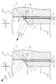
次いで、図17から図36を参照して、特別入賞装置550について説明する。初めに、図17を参照して、特別入賞装置550の配設方法について説明する。図17は、センターフレーム86の分解斜視正面図である。   Next, the special winning device 550 will be described with reference to FIGS. 17 to 36. First, with reference to FIG. 17, a method for arranging the special prize-winning device 550 will be described. FIG. 17 is an exploded perspective front view of the center frame 86.

図17に示すように、センターフレーム86は、ベース板60の中央の開口を取り囲む略円形の枠状に形成されるベース枠86aと、そのベース枠86aの径方向外側に突出される突設部86bと、を備えて構成される。   As shown in FIG. 17, the center frame 86 includes a base frame 86a formed in a substantially circular frame shape surrounding the central opening of the base plate 60, and a projecting portion protruding outward in the radial direction of the base frame 86a. 86b.

ベース枠86aは、ベース板60の中央の開口に沿う形状とされ、その中央の開口の内側にベース枠86aの一部が挿入されると共に、ベース枠86aの一部を除く部分がベース板60の正面側に張り出した状態でベース板60に配設される。   The base frame 86a is shaped along the central opening of the base plate 60, and a part of the base frame 86a is inserted inside the central opening, and a portion excluding a part of the base frame 86a is the base plate 60. It is arrange | positioned by the base board 60 in the state projected over the front side.

突設部86bは、遊技盤13の遊技領域に対して、正面視右側(矢印R方向側)に突設される。これにより、突設部86bに配設される特別入賞装置550を遊技領域に対して正面視右側(矢印R方向側)に配設することができ、特別遊技状態となった際の右打ち時の遊技球の送球経路の一部を特別入賞装置550により構成することができる。   The projecting portion 86 b is projected from the game area of the game board 13 on the right side in the front view (arrow R direction side). Thereby, the special prize-winning device 550 arranged in the projecting portion 86b can be arranged on the right side (arrow R direction side) in front view with respect to the gaming area, and when the player enters the special gaming state, A part of the pitch of the game balls can be constituted by the special prize-winning device 550.

また、突設部86bは、前後方向(矢印F−B方向)に開口する開口部86b1と、その開口部86b1の上方(矢印U方向)に位置し背面側(矢印B方向側)に向かって凹設される凹部86b2と、を主に備える。   The projecting portion 86b has an opening 86b1 that opens in the front-rear direction (arrow FB direction), and is located above the opening 86b1 (arrow U direction) and toward the back side (arrow B direction side). And a recessed portion 86b2 that is recessed.

開口部86b1は、後述する特別入賞装置550の第1ユニット551の一部が挿入される。これにより、第1ユニット551を、突設部86bの背面側に配設される特別入賞装置550の第2ユニット552と開口部86b1を介して連結することができる。   A part of the first unit 551 of the special prize device 550 described later is inserted into the opening 86b1. Thus, the first unit 551 can be connected to the second unit 552 of the special prize device 550 disposed on the back side of the protruding portion 86b via the opening 86b1.

凹部86b2は、後述する特別入賞装置550の第1ユニット551の一部を内側に収容可能とされる。また、凹部86b2には、遊技球の通過を検知可能な検出装置86b3が配設される。これにより、第1ユニット551の凹部86b2の内側に収容される部分を通過する遊技球を検出することができる。   The recess 86b2 can accommodate a part of the first unit 551 of the special prize device 550 described later. In addition, a detection device 86b3 that can detect the passage of the game ball is disposed in the recess 86b2. Thereby, it is possible to detect the game ball passing through the portion accommodated inside the recess 86b2 of the first unit 551.

特別入賞装置550は、センターフレーム86の突設部86bの正面側(矢印F方向側)に配設される第1ユニット551と、突設部86bの背面側(矢印B方向側)に配設される第2ユニット552と、を主に備えて構成される。   The special prize-winning device 550 is disposed on the front side (arrow F direction side) of the projecting portion 86b of the center frame 86, and on the back side (arrow B direction side) of the projecting portion 86b. The second unit 552 is mainly provided.

第1ユニット551は、その内部を遊技球が流下可能な空間(経路)を備え、一部が遊技盤13の遊技領域に配設される。また、第1ユニット551は、第2ユニット552を挿通されたネジによりセンターフレーム86に配設される。なお、第1ユニット551及び第2ユニット552の配設方法についての詳しい説明は後述する。   The first unit 551 has a space (path) through which the game ball can flow down, and a part thereof is disposed in the game area of the game board 13. The first unit 551 is disposed on the center frame 86 with screws inserted through the second unit 552. A detailed description of the arrangement method of the first unit 551 and the second unit 552 will be described later.

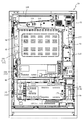
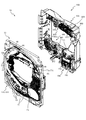
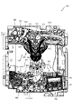
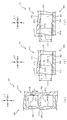
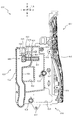
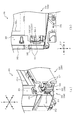
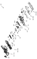
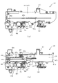
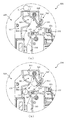
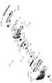
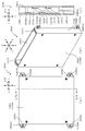
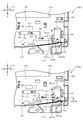
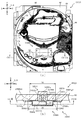
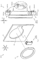
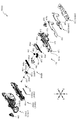
次いで、図18から図20を参照して、特別入賞装置550の第1ユニット551の構成について説明する。図18(a)は、第1ユニット551の正面図であり、図18(b)は、第1ユニット551の側面図であり、図18(c)は、第1ユニット551の背面図である。図19は、第1ユニット551の分解斜視正面図であり、図20は、第1ユニット551の分解斜視背面図である。   Next, the configuration of the first unit 551 of the special winning device 550 will be described with reference to FIGS. 18 (a) is a front view of the first unit 551, FIG. 18 (b) is a side view of the first unit 551, and FIG. 18 (c) is a rear view of the first unit 551. . FIG. 19 is an exploded perspective front view of the first unit 551, and FIG. 20 is an exploded perspective rear view of the first unit 551.

図18から図20に示すように、第1ユニット551は、正面側に配設される第1経路部材560と、その第1経路部材560の背面側に配設される第2経路部材570と、その第2経路部材570の背面に配設される第3経路部材580と、を主に備えて形成される。   As shown in FIGS. 18 to 20, the first unit 551 includes a first path member 560 disposed on the front side, and a second path member 570 disposed on the back side of the first path member 560. The third path member 580 disposed on the back surface of the second path member 570 is mainly provided.

第1経路部材560は、遊技盤13の遊技領域の正面に沿った板状に形成される正面板564と、上方側(矢印U方向側)が開放する断面略U字状に形成され、正面板564の上方側端部から背面側に突設される第1受入部561、第2受入部562及び第3受入部563と、その第1受入部561、第2受入部562及び第3受入部563の下側(矢印D方向側)に連なって形成されると共に、正面板564の一部の端部に沿って延設される第1壁部565と、その第1壁部565の下方に形成され、所定の間隔を隔てた2箇所から突設される2組の第2壁部566及び第3壁部567と、を主に備える。   The first path member 560 has a front plate 564 formed in a plate shape along the front of the game area of the game board 13 and a substantially U-shaped cross section that opens upward (arrow U direction side). A first receiving portion 561, a second receiving portion 562, and a third receiving portion 563 that protrude from the upper end of the face plate 564 to the back side, and the first receiving portion 561, the second receiving portion 562, and the third receiving portion. A first wall portion 565 formed continuously with the lower side (arrow D direction side) of the portion 563 and extending along a part of the end portion of the front plate 564, and below the first wall portion 565 2 sets of 2nd wall part 566 and 3rd wall part 567 which are formed in 2 and protruded from two places spaced apart by predetermined spacing are mainly provided.

正面板564は、後述する第2経路部材570又は第3経路部材580との対向間に形成される遊技球の流下経路の正面側の壁部となる板部材であり、光透過部材から形成される。これにより、遊技者は、第1ユニット551の内部を流下する遊技球を正面板564を介して(通して)視認することができる。   The front plate 564 is a plate member that serves as a wall portion on the front side of the flow path of a game ball formed between facing a second path member 570 or a third path member 580 described later, and is formed of a light transmitting member. The Thereby, the player can visually recognize the game ball flowing down inside the first unit 551 through (through) the front plate 564.

また、正面板564は、第2経路部材570側(背面側(矢印B方向側)に突設される案内部564aを備える。   Further, the front plate 564 includes a guide portion 564a that protrudes on the second path member 570 side (back side (arrow B direction side)).

案内部564aは、第1ユニット551の内側を流下する遊技球により、正面板564の壁面の全域が汚れることを抑制する壁部であり、後述する第2経路部材570又は第3経路部材580との対向間を流下する遊技球の流下経路に沿って延設される。また、案内部564aは、第1ユニット551を流下する遊技球の転動面から遊技球の半径分離れた位置に突設される。言い換えると、案内部564aは、第1経路部材560を流下する遊技球の中心位置と、略同一の位置に突設される。これにより、正面板564と遊技球とが当接する部分を案内部564aの突設先端部に限定することができる。従って、正面板564の全域に遊技球と当接することにより傷が生じることや遊技球に付着した汚れが移着することを抑制できる。その結果、正面板564を介して第1経路部材560の内部を流下する遊技球を遊技者に視認させやすくできる。   The guide portion 564a is a wall portion that suppresses the entire area of the wall surface of the front plate 564 from being soiled by the game balls flowing down the inside of the first unit 551, and the second route member 570 or the third route member 580 to be described later. It extends along the flow path of the game ball flowing down between the opposite sides. In addition, the guide portion 564a is provided so as to protrude from the rolling surface of the game ball flowing down the first unit 551 at a position separated from the radius of the game ball. In other words, the guide portion 564a protrudes at a position substantially the same as the center position of the game ball flowing down the first path member 560. Thereby, the part which the front board 564 and a game ball contact | abut can be limited to the protrusion front-end | tip part of the guide part 564a. Accordingly, it is possible to suppress the generation of scratches due to contact with the game ball over the entire area of the front plate 564 and the transfer of dirt attached to the game ball. As a result, it is possible to make it easier for the player to visually recognize the game ball flowing down inside the first path member 560 via the front plate 564.

第1受入部561、第2受入部562及び第3受入部563は、第1ユニット551の上方(矢印U方向)の遊技領域から流下する遊技球を第1ユニット551の内部に受け入れる部分であり、上方側の開口が遊技球の直径よりも大きい寸法に設定される。また、第1受入部561、第2受入部562及び第3受入部563は、正面板564の上方側(矢印U方向側)の端部に左右方向(矢印L−R方向)に並設される。   The first receiving portion 561, the second receiving portion 562, and the third receiving portion 563 are portions that receive game balls flowing down from the game area above (in the direction of arrow U) the first unit 551 into the first unit 551. The upper opening is set to a size larger than the diameter of the game ball. The first receiving portion 561, the second receiving portion 562, and the third receiving portion 563 are juxtaposed in the left-right direction (arrow LR direction) at the upper end (arrow U direction side) of the front plate 564. The

第1受入部561は、第2受入部562及び第3受入部563よりも遊技球の受け入れ幅(左右方向(矢印L−R方向)の幅寸法)が大きく設定される。これにより、特別入賞装置550に流入する遊技球は、第2受入部562又は第3受入部563よりも第1受入部561に流入しやすくされる。   The first receiving portion 561 is set to have a larger game ball receiving width (width dimension in the left-right direction (arrow LR direction)) than the second receiving portion 562 and the third receiving portion 563. As a result, the game balls flowing into the special winning device 550 are more likely to flow into the first receiving unit 561 than the second receiving unit 562 or the third receiving unit 563.

また、第1受入部561は、第1ユニット551の内側に形成される流下経路に連通される。これにより、第1受入部561に受け入れられた遊技球は、第1ユニット551の内側を流下される。なお、第1ユニット551の遊技球の流下経路については後述する。   Further, the first receiving part 561 is communicated with a flow path formed inside the first unit 551. As a result, the game balls received by the first receiving unit 561 flow down inside the first unit 551. The flow path of the game balls of the first unit 551 will be described later.

第2受入部562及び第3受入部563は、後述する第2ユニット552の内側に形成される流下経路に連通される。これにより、第2受入部562及び第3受入部563に受け入れられた遊技球が第2ユニット552の内側を流下される。なお、第2ユニット552の流下経路については後述する。   The 2nd receiving part 562 and the 3rd receiving part 563 are connected to the flow-down path formed inside the 2nd unit 552 mentioned below. As a result, the game balls received by the second receiving unit 562 and the third receiving unit 563 flow down inside the second unit 552. The flow path of the second unit 552 will be described later.

第1壁部565は、後述する第2経路部材570に形成される第4壁部573との対向間に遊技球を送球する空間を形成する内壁である。第1壁部565は、一端が上述した第1受入部561の下方側に連結され、他端側が第2受入部562及び第3受入部563の下側に亘って左右方向(矢印L−R方向)に延設される上方側壁部565aと、背面視略C字状に湾曲して形成され上方側壁部565aに連結する湾曲壁部565bと、から主に構成される。   The 1st wall part 565 is an inner wall which forms the space which sends a game ball between facing the 4th wall part 573 formed in the 2nd path | route member 570 mentioned later. One end of the first wall portion 565 is connected to the lower side of the first receiving portion 561 described above, and the other end side extends to the lower side of the second receiving portion 562 and the third receiving portion 563 (arrow LR). Direction wall) and a curved wall portion 565b that is curved in a substantially C shape when viewed from the back and is connected to the upper side wall portion 565a.

上方側壁部565aは、後述する第4壁部573の上面(矢印U方向側の面)を遊技球が転動する際に、その転動面の上方を覆う内壁であり、第4壁部573の上面と直交する方向に遊技球の直径よりも上方側(矢印U方向側)に離間する位置に形成される。   The upper side wall portion 565a is an inner wall that covers the upper surface of the rolling surface when the game ball rolls on the upper surface (the surface on the arrow U direction side) of a fourth wall portion 573, which will be described later, and the fourth wall portion 573. It is formed at a position that is separated upward (arrow U direction side) from the diameter of the game ball in a direction perpendicular to the upper surface of the game ball.

湾曲壁部565bは、後述する第4壁部573の上面を転動する遊技球の転動方向を変更する内壁であり、第4壁部573の転動側端部と対向する位置に形成される。また、湾曲壁部565bは、第4壁部573の転動側端部を中心とする半円弧状に形成される。これにより、第4壁部573の上面を転動する遊技球を、湾曲壁部565bの内壁に沿って流下させることで、第4壁部573の下面側に案内することができると共に、その転動方向を第4壁部573の上面の転動方向と反対にすることができる。   The curved wall portion 565b is an inner wall that changes the rolling direction of a game ball that rolls on the upper surface of a fourth wall portion 573, which will be described later, and is formed at a position facing the rolling side end of the fourth wall portion 573. The Further, the curved wall portion 565b is formed in a semicircular arc shape centering on the rolling side end portion of the fourth wall portion 573. Thereby, the game ball rolling on the upper surface of the fourth wall portion 573 can be guided to the lower surface side of the fourth wall portion 573 by flowing down along the inner wall of the curved wall portion 565b, and the rolling can be performed. The moving direction can be opposite to the rolling direction of the upper surface of the fourth wall portion 573.

第2壁部566は、第1ユニット551の内部を流下する遊技球の主の流下経路から分岐する経路の空間を形成する内壁であり、正面板564の背面から突設される一対の壁部の対向間が、遊技球の直径よりも若干大きい寸法に設定される。これにより、第1ユニット551を流下する経路を増やすことができる。   The second wall portion 566 is an inner wall that forms a space of a path that branches off from the main flow path of the game ball that flows down inside the first unit 551, and a pair of wall sections that protrude from the back surface of the front plate 564. Is set to a size slightly larger than the diameter of the game ball. Thereby, the path | route which flows down the 1st unit 551 can be increased.

第3壁部567は、第1ユニット551の内部を流下する遊技球の主の送球経路(主経路SK3)から分岐する経路の内面を形成する壁部であり、正面板564の背面から突設される一対の壁部の対向間が、遊技球の直径よりも若干大きい寸法に設定される。これにより、第1ユニット551を流下する遊技球の経路を増やすことができる。   The third wall portion 567 is a wall portion that forms the inner surface of a path that branches off from the main pitching path (main path SK3) of the game ball that flows down inside the first unit 551, and projects from the back surface of the front plate 564. The distance between the pair of wall portions facing each other is set to be slightly larger than the diameter of the game ball. Thereby, the path | route of the game ball which flows down the 1st unit 551 can be increased.

また、第2壁部566と第3壁部567とは、それぞれ下流側の端部が第1ユニット551の左右方向(矢印L−R方向)の反対側に配置される。これにより、後述する分岐通路から第1ユニット551の左右方向の両側に遊技球を送球することができる。   In addition, the second wall portion 566 and the third wall portion 567 are respectively arranged on the opposite sides of the first unit 551 in the left-right direction (arrow LR direction). Thereby, a game ball can be sent to the both sides of the left-right direction of the 1st unit 551 from the branch passage mentioned later.

第2経路部材570は、第1経路部材560の正面板564と対向する板状のベース板571と、そのベース板571の正面から第1経路部材560側に突設される第4壁部573と、その第4壁部573から下方側に所定の距離離間する位置に突設される第5壁部574と、その第5壁部574から下方側に所定の距離離間する位置に突設される第6壁部575と、を主に備えて形成される。   The second path member 570 includes a plate-like base plate 571 that faces the front plate 564 of the first path member 560, and a fourth wall portion 573 that projects from the front surface of the base plate 571 toward the first path member 560. And a fifth wall portion 574 protruding from the fourth wall portion 573 at a predetermined distance downward, and a fifth wall portion 574 protruding at a predetermined distance from the fifth wall portion 574 downward. And a sixth wall portion 575.

ベース板571は、第1経路部材560の正面板564と遊技球の直径よりも若干大きい距離を隔てる位置に配設される。これにより、正面板564とベース板571との間に遊技球を流下させることができる。また、ベース板571は、第1受入部561、第2受入部562及び第3受入部563のそれぞれに対応する位置に開口する第1開口部571a、第2開口部571b及び第3開口部571cと、第1開口部571aの下方に開口する第4開口部571dと、第5壁部574及び第6壁部575のそれぞれの上方に開口する第5開口部571e及び第6開口部571fと、第5壁部574および第6壁部575の間に位置し背面側に凹設される凹設部571gと、を備える。   The base plate 571 is disposed at a position that is separated from the front plate 564 of the first path member 560 by a distance slightly larger than the diameter of the game ball. Thereby, the game ball can flow down between the front plate 564 and the base plate 571. The base plate 571 includes a first opening 571a, a second opening 571b, and a third opening 571c that open to positions corresponding to the first receiving portion 561, the second receiving portion 562, and the third receiving portion 563, respectively. A fourth opening 571d that opens below the first opening 571a, a fifth opening 571e and a sixth opening 571f that open above the fifth wall 574 and the sixth wall 575, respectively. A recessed portion 571g which is located between the fifth wall portion 574 and the sixth wall portion 575 and is recessed on the back surface side.

第1開口部571a、第2開口部571b及び第3開口部571cは、上述した第1経路部材560の第1受入部561、第2受入部562及び第3受入部563に流入する遊技球をベース板571の背面側に通過させる開口である。   The first opening 571a, the second opening 571b, and the third opening 571c are used to play game balls that flow into the first receiving portion 561, the second receiving portion 562, and the third receiving portion 563 of the first path member 560 described above. This is an opening that passes through the back side of the base plate 571.

また、ベース板571は、第1開口部571a、第2開口部571b及び第3開口部571cの下側端部から背面側に突出する第1転動部576、第2転動部577及び第3転動部578を備える。これにより、第1開口部571aを通過する遊技球は、後述する第3経路部材580に、第2開口部571b又は第3開口部571cを通過する遊技球は、後述する第2ユニット552に、それぞれ送球される。   In addition, the base plate 571 includes a first rolling part 576, a second rolling part 577, and a first rolling part 576 that protrude from the lower end of the first opening part 571a, the second opening part 571b, and the third opening part 571c to the back side. Three rolling parts 578 are provided. Thereby, a game ball passing through the first opening 571a is transferred to a third path member 580 described later, and a game ball passing through the second opening 571b or the third opening 571c is transferred to a second unit 552 described later. Each ball is sent.

第1開口部571a及び第4開口部571dは、背面側に後述する第3経路部材580の一部が覆設される。これにより、第1開口部571aを通過する遊技球は、第4開口部571dからベース板571の正面側(矢印F方向側)に送球される。   The first opening portion 571a and the fourth opening portion 571d are partially covered with a third path member 580 described later on the back side. Thereby, the game ball passing through the first opening 571a is sent to the front side (arrow F direction side) of the base plate 571 from the fourth opening 571d.

第4壁部573は、第4開口部571dの下側端部に沿ってベース板571から突設されると共に、左右方向(矢印L−R方向)に延設される。また、第4壁部573は、ベース板571の正面視左側に開口される第4開口部571d側から正面視右側(矢印R方向側)に向かう程、上面が下方に傾斜して形成される。これにより、第4開口部571dを通過してベース板571の正面側に送球される遊技球を、第4壁部573の上面に乗せると共に、第4壁部573の上面の傾斜によりベース板571の右側(矢印R方向側)に送球できる。   The fourth wall 573 protrudes from the base plate 571 along the lower end of the fourth opening 571d and extends in the left-right direction (arrow LR direction). The fourth wall portion 573 is formed such that the upper surface is inclined downward as it goes from the fourth opening portion 571d opened to the left side of the base plate 571 in the front view to the right side of the front view (arrow R direction side). . Thereby, the game ball that passes through the fourth opening 571d and is sent to the front side of the base plate 571 is placed on the upper surface of the fourth wall portion 573, and the base plate 571 is inclined by the inclination of the upper surface of the fourth wall portion 573. Can be sent to the right side (arrow R direction side).

第5壁部574は、上述した第1壁部565の湾曲壁部565bから送球される遊技球の転動面となる部分であり、第4壁部573の下面と直交する方向に遊技球の直径よりも下方側に離間する位置に突設されると共に、ベース板571の左右方向(矢印L−R方向)に延設される。また、第5壁部は、湾曲壁部565b側(矢印R方向側)から後述する凹設部574g側(矢印L方向側)に向かう程、上面(矢印U方向側の面)が下方に傾斜して形成される。これにより、湾曲壁部565bから第5壁部574の上面に送球される遊技球を、凹設部574g側に転動させることができる。さらに、第5壁部574は、遊技球の転動面に下方側に向かって凹む第1受入凹部574a及び第2受入凹部574bを備える。   The fifth wall portion 574 is a portion serving as a rolling surface of the game ball sent from the curved wall portion 565b of the first wall portion 565 described above, and the game ball is placed in a direction perpendicular to the lower surface of the fourth wall portion 573. The base plate 571 extends in the left-right direction (arrow L-R direction) and protrudes at a position spaced apart from the diameter. Further, the upper surface (the surface on the arrow U direction side) of the fifth wall portion is inclined downward from the curved wall portion 565b side (the arrow R direction side) toward the recessed portion 574g side (the arrow L direction side) described later. Formed. Thereby, the game ball sent to the upper surface of the 5th wall part 574 from the curved wall part 565b can be rolled to the recessed part 574g side. Furthermore, the fifth wall 574 includes a first receiving recess 574a and a second receiving recess 574b that are recessed downward on the rolling surface of the game ball.

第1受入凹部574a及び第2受入凹部574bは、第5壁部574の延設方向に並設される。また、第1受入凹部574a及び第2受入凹部574bは、凹設幅および凹設深さが、遊技球の直径よりも大きい寸法に設定される。さらに、第1受入凹部574a及び第2受入凹部574bの内側には、ベース板571に開口する第5開口部571eが形成される。これにより、第1受入凹部574a又は第2受入凹部574bに流入する遊技球は、第5開口部571eを通過してベース板571の背面側に送球される。   The first receiving recess 574a and the second receiving recess 574b are juxtaposed in the extending direction of the fifth wall 574. Further, the first receiving recess 574a and the second receiving recess 574b are set such that the recess width and the recess depth are larger than the diameter of the game ball. Furthermore, a fifth opening 571e that opens to the base plate 571 is formed inside the first receiving recess 574a and the second receiving recess 574b. Thereby, the game ball flowing into the first receiving recess 574a or the second receiving recess 574b passes through the fifth opening 571e and is sent to the back side of the base plate 571.

凹設部574gは、第5壁部574の下流側端部(矢印L方向側の端部)の上方に形成されており、第5壁部574の上面を転動する遊技球を凹設部574gの内側に流入させると共に凹設部574gの下方(矢印D方向)に形成される第6壁部575の上部に送球することができる。   The recessed portion 574g is formed above the downstream end portion (end portion on the arrow L direction side) of the fifth wall portion 574, and the recessed portion is provided with a game ball that rolls on the upper surface of the fifth wall portion 574. It can be made to flow inside 574g, and can be sent to the upper part of the 6th wall part 575 formed in the downward direction (arrow D direction) of the recessed part 574g.

第6壁部575は、第5壁部574を転動して凹設部574gに送球される遊技球の転動面となる部分であり、第5壁部574の下面から下方側に遊技球の直径よりも離間する位置でベース板571から突設され、ベース板571の左右方向(矢印L−R)方向に延設される。また、第6壁部575は、凹設部574g側(矢印L方向側)から上述した第3壁部567側に向かって上面が下方に傾斜して形成される。これにより、凹設部574gから第6壁部575の上面に送球される遊技球を、第3壁部567により形成される送球経路側に転動させることができる。また、第6壁部575は、遊技球の転動面に下方側に向かって凹む第3受入凹部575a及び第4受入凹部575bを備える。   The sixth wall portion 575 is a portion that becomes a rolling surface of a game ball that rolls on the fifth wall portion 574 and is sent to the recessed portion 574g, and a game ball is formed downward from the lower surface of the fifth wall portion 574. The base plate 571 protrudes from the base plate 571 at a position separated from the diameter of the base plate 571 and extends in the left-right direction (arrow LR). The sixth wall portion 575 is formed such that the upper surface is inclined downward from the recessed portion 574g side (arrow L direction side) toward the above-described third wall portion 567 side. Thereby, the game ball sent to the upper surface of the sixth wall portion 575 from the recessed portion 574g can be rolled to the pitching path side formed by the third wall portion 567. The sixth wall portion 575 includes a third receiving recess 575a and a fourth receiving recess 575b that are recessed downward on the rolling surface of the game ball.

第3受入凹部575a及び第4受入凹部575bは、第6壁部575の延設方向に並設される。また、第3受入凹部575a及び第4受入凹部575bは、凹設幅および凹設深さが、遊技球の直径よりも大きい寸法に設定される。さらに、第3受入凹部575a及び第4受入凹部575bの内側には、ベース板571に開口する第6開口部571fが形成される。これにより、第3受入凹部575a及び第4受入凹部575bに流入した遊技球は、第6開口部571fを通過してベース板571の背面側に送球される。   The third receiving recess 575a and the fourth receiving recess 575b are juxtaposed in the extending direction of the sixth wall portion 575. Further, the third receiving recess 575a and the fourth receiving recess 575b are set such that the recess width and the recess depth are larger than the diameter of the game ball. Furthermore, a sixth opening 571f that opens to the base plate 571 is formed inside the third receiving recess 575a and the fourth receiving recess 575b. Thereby, the game ball that has flowed into the third receiving recess 575a and the fourth receiving recess 575b passes through the sixth opening 571f and is sent to the back side of the base plate 571.

第3経路部材580は、第2経路部材570の重力方向上方側(矢印U方向側)の背面に配設される第1覆設部材581と、第2経路部材570の重力方向下方側(矢印D方向側)の背面に配設される第2覆設部材582と、第1覆設部材581及び第2覆設部材582の間に配設される第1駆動ユニット583と、第2覆設部材582の背面に配設される第2駆動ユニット584とを主に備えて構成される。   The third path member 580 includes a first covering member 581 disposed on the rear surface of the second path member 570 on the upper side in the gravity direction (arrow U direction side), and the lower side in the gravity direction of the second path member 570 (arrow). A second covering member 582 disposed on the back surface on the D direction side, a first drive unit 583 disposed between the first covering member 581 and the second covering member 582, and a second covering member. A second drive unit 584 disposed on the back surface of the member 582 is mainly provided.

第1覆設部材581は、上述した第1開口部571a及び第4開口部571dの背面側に配設される湾曲部581aと、その湾曲部581aの下方側に連なる板状の取付部581bと、を主に備える。   The first covering member 581 includes a curved portion 581a disposed on the back side of the first opening portion 571a and the fourth opening portion 571d described above, and a plate-like attachment portion 581b continuous to the lower side of the curved portion 581a. Is mainly provided.

湾曲部581aは、第1開口部571a及び第4開口部571d(第2経路部材570)側が開放される断面U字状に湾曲して形成され、その内側に第1転動部576が配設される(図24(a)参照)。また、湾曲部581aの湾曲内側の壁面と第1転動部576の突設先端部との離間距離は、遊技球の直径よりも大きく設定される。これにより、第1転動部576を転動する遊技球を湾曲部581aの内壁に沿って流下させて、第1転動部581aの下方側に送球することができる。よって、背面側に湾曲する湾曲部581aに遊技球を送球することで、遊技球の転動時間を長くすることができる。その結果、遊技盤13の遊技領域と平行な平面上に遊技球の転動面を確保できない場合でも、遊技球の転動速度を遅くすることができる。   The curved portion 581a is formed to be curved in a U-shaped cross section in which the first opening portion 571a and the fourth opening portion 571d (second path member 570) side are opened, and the first rolling portion 576 is disposed inside the curved portion 581a. (See FIG. 24A). Further, the separation distance between the inner wall surface of the bending portion 581a and the protruding tip portion of the first rolling portion 576 is set to be larger than the diameter of the game ball. Thereby, the game ball rolling on the first rolling part 576 can flow down along the inner wall of the curved part 581a and can be sent to the lower side of the first rolling part 581a. Therefore, the rolling time of the game ball can be extended by sending the game ball to the bending portion 581a that curves to the back side. As a result, even when the rolling surface of the game ball cannot be secured on a plane parallel to the game area of the game board 13, the rolling speed of the game ball can be slowed down.

さらに、湾曲部581aは、下方側の端部が、第4開口部571dの下側内縁よりも若干高い位置に配置される。これにより、第1転動部576から湾曲部581aの内壁に沿って流下されて第4開口部571dに送球された遊技球が逆流して、湾曲部581aの内側に流入することを抑制できる。   Further, the curved portion 581a is disposed at a position where the lower end is slightly higher than the lower inner edge of the fourth opening 571d. Thereby, it is possible to suppress the gaming ball that has flowed down from the first rolling portion 576 along the inner wall of the bending portion 581a and sent to the fourth opening portion 571d to flow back into the bending portion 581a.

取付部581bは、第1覆設部材581を第2経路部材570の背面に締結するためのネジを挿通する貫通孔581b1が2箇所に貫通形成される。また、取付部581bは、背面側に向かって円柱状に突設される柱状体551aを備える。柱状体551aは、後述する第2ユニット552を第1ユニット551に締結するためのネジ穴が先端に穿設される。これにより、第2ユニット552の背面側から挿通されるネジを柱状体551aに螺合させて第1ユニット551と第2ユニット552とを締結することができる。   The attachment portion 581b is formed with two through holes 581b1 through which screws for fastening the first covering member 581 to the back surface of the second path member 570 are inserted. In addition, the attachment portion 581b includes a columnar body 551a that protrudes in a columnar shape toward the back side. The columnar body 551a has a screw hole at the tip for fastening a second unit 552, which will be described later, to the first unit 551. Accordingly, the first unit 551 and the second unit 552 can be fastened by screwing the screw inserted from the back side of the second unit 552 into the columnar body 551a.

第2覆設部材582は、第6開口部571fの背面側に配設される第2湾曲部582aと、第1受入凹部574a〜第4受入凹部575bの背面側に配設される背面側壁部582bと、を主に備える。   The second covering member 582 includes a second curved portion 582a disposed on the back side of the sixth opening 571f and a back side wall portion disposed on the back side of the first receiving recess 574a to the fourth receiving recess 575b. 582b.

第2湾曲部582aは、第6開口部571f(第2経路部材570)側が開放される断面U字状に湾曲して形成される(図24(c)参照)。また、第2湾曲部582aは、正面側から背面側に向かって立設される立設壁582a1をU字の内側に備える。立設壁582a1により、第2湾曲部582aの内部空間が、正面視左側(矢印L方向側)の第1空間582a2と、立設壁582a1を間に挟んで第1空間582a2の隣に形成される第2空間582a3とに分けられる。   The second curved portion 582a is formed to be curved in a U-shaped cross section where the sixth opening 571f (second path member 570) side is opened (see FIG. 24C). Moreover, the 2nd bending part 582a equips the inner side of U character with the standing wall 582a1 standingly arranged toward the back side from the front side. Due to the standing wall 582a1, the internal space of the second bending portion 582a is formed next to the first space 582a2 on the left side in the front view (arrow L direction side) and the first space 582a2 with the standing wall 582a1 interposed therebetween. And the second space 582a3.

第1空間582a2及び第2空間582a3は、遊技球の直径よりも大きい空間であり、正面側から背面側に向かって形成される。また、第1空間582a2及び第2空間582a3は、背面側で連結される。また、第1空間582a2の内面は、背面側に向かう程、下方に傾斜して形成され、第2空間582a3の内面は正面側に向かう程、下方に傾斜して形成される。これにより、凹設部571gから第2湾曲部582aに送球される遊技球は、第1空間582a2の傾斜により、背面側に転動されると共に背面側の端部で第2湾曲部582aの湾曲により第2空間582a3に送球され、第2空間582a3の傾斜により正面側に転動され、第6開口部571fの開口を通過して、ベース板571の正面側に送球される。   The first space 582a2 and the second space 582a3 are spaces larger than the diameter of the game ball, and are formed from the front side toward the back side. The first space 582a2 and the second space 582a3 are connected on the back side. Further, the inner surface of the first space 582a2 is formed to be inclined downward toward the back side, and the inner surface of the second space 582a3 is formed to be inclined downward as it is directed to the front side. Thereby, the game ball sent from the recessed portion 571g to the second bending portion 582a is rolled to the back side due to the inclination of the first space 582a2, and the second bending portion 582a is bent at the end on the back side. Is sent to the second space 582a3, rolled to the front side by the inclination of the second space 582a3, passed through the opening of the sixth opening 571f, and sent to the front side of the base plate 571.

背面側壁部582bは、第1受入凹部574a〜第4受入凹部575bに送球されて、第5開口部571e及び第6開口部571fを通過する遊技球を特別入賞装置550の下方に案内する送球経路の背面側の壁部である。これにより、第1受入凹部574a〜第4受入凹部575bに送球される遊技球を回収することができる。従って、第1受入凹部574a〜第4受入凹部575bに送球されて、後述する検出装置SE3〜SE6を通過して遊技価値を遊技者に付与した遊技球が再度遊技領域を流下して、遊技価値が再度遊技者に付与されることを防止できる。   The back side wall portion 582b is sent to the first receiving recess 574a to the fourth receiving recess 575b, and the pitching path for guiding the game balls passing through the fifth opening 571e and the sixth opening 571f below the special winning device 550. It is the wall part of the back side. Thereby, the game ball sent to the 1st receiving recessed part 574a-the 4th receiving recessed part 575b can be collect | recovered. Therefore, the game balls that have been sent to the first receiving recess 574a to the fourth receiving recess 575b, passed through the detection devices SE3 to SE6 described later, and have been given game value to the player again flow down the game area, and the game value Can be prevented from being given to the player again.

第1駆動ユニット583は、電力により前後方向に変位する軸を備える第1ソレノイド583aと、その第1ソレノイド583aの軸に連結される第1可変板583bと、第1ソレノイド583a及び第1可変板583bの周囲を囲む第1保護部材583cと、を主に備える。   The first drive unit 583 includes a first solenoid 583a having a shaft that is displaced in the front-rear direction by electric power, a first variable plate 583b connected to the shaft of the first solenoid 583a, the first solenoid 583a, and the first variable plate. A first protective member 583c surrounding the periphery of 583b.

第1可変板583bは、左右方向(矢印L−R方向)に長い矩形状の板部材であり、第1ソレノイド583aの軸の変位に合わせて前後方向(矢印F−B方向)に変位される。また、第1可変板583bが正面側に張り出された状態では、その第1可変板583bの先端が上述した第5開口部571eに挿入されると共に、第1受入凹部574a及び第2受入凹部574bの上側に配置される。これにより、第1可変板583bが正面側に張り出された状態では、その第1可変板583bにより第1受入凹部574a及び第2受入凹部574bへの遊技球の流入を防止することができる。   The first variable plate 583b is a rectangular plate member that is long in the left-right direction (arrow LR direction), and is displaced in the front-rear direction (arrow FB direction) in accordance with the displacement of the shaft of the first solenoid 583a. . Further, in a state where the first variable plate 583b is projected to the front side, the tip of the first variable plate 583b is inserted into the above-described fifth opening 571e, and the first receiving recess 574a and the second receiving recess. It is arranged on the upper side of 574b. Thereby, in a state where the first variable plate 583b is projected to the front side, the first variable plate 583b can prevent the inflow of game balls to the first receiving recess 574a and the second receiving recess 574b.

第1保護部材583cは、第2経路部材570側が開放する箱状に形成され、その内部に第1ソレノイド583aの軸と第1可変板583bとを連結する機構が配設される。また、第1保護部材583cは、前後方向に貫通する貫通孔583c1を複数備える。   The first protection member 583c is formed in a box shape that opens on the second path member 570 side, and a mechanism for connecting the shaft of the first solenoid 583a and the first variable plate 583b is disposed therein. The first protective member 583c includes a plurality of through holes 583c1 penetrating in the front-rear direction.

貫通孔583c1は、第1駆動ユニット583を第2経路部材570に締結するためのネジを挿通する部分である。貫通孔583c1を挿通されたネジは、第1覆設部材581の貫通孔581b1、又は、第2覆設部材582の貫通孔582b1を挿通されて、第2経路部材570に穿設される孔に螺合される。よって、第1駆動ユニット583を第2経路部材570に配設することで、第1覆設部材581及び第2覆設部材582を第2経路部材570に配設することができる。これにより、第1覆設部材581及び第2覆設部材582のネジの締結部分を少なくすることができ、製造コストを削減できる。   The through hole 583c1 is a portion through which a screw for fastening the first drive unit 583 to the second path member 570 is inserted. The screw inserted through the through-hole 583c1 is inserted into the through-hole 581b1 of the first covering member 581 or the through-hole 582b1 of the second covering member 582, and is a hole formed in the second path member 570. Screwed together. Therefore, by arranging the first drive unit 583 on the second path member 570, the first covering member 581 and the second covering member 582 can be disposed on the second path member 570. Thereby, the fastening part of the screw of the 1st covering member 581 and the 2nd covering member 582 can be decreased, and manufacturing cost can be reduced.

また、第1覆設部材581又は第2覆設部材582を第2経路部材570と第1駆動ユニット583との間に挟んだ状態とすることができるので、第1駆動ユニット583が、特別入賞装置550から無理に外された場合に、第1覆設部材581又は第2覆設部材582と第2経路部材570との締結を不完全として、遊技球が第1覆設部材581又は第2覆設部材582を通過できない状態としやすい。その結果、不正がされた状態で、遊技が継続されることを抑制できる。   Further, since the first covering member 581 or the second covering member 582 can be sandwiched between the second path member 570 and the first drive unit 583, the first drive unit 583 can receive a special prize. When it is forcibly removed from the device 550, the first covering member 581 or the second covering member 582 and the second path member 570 are incompletely fastened, and the game ball is moved to the first covering member 581 or the second covering member 581. It is easy to make it impossible to pass through the covering member 582. As a result, it is possible to prevent the game from being continued in a state of being cheated.

第2駆動ユニット584は、第1駆動ユニット583と同様に、電力により前後方向に変位する軸を備える第2ソレノイド584aと、その第2ソレノイド584aの軸に連結される第2可変板584bと、第2ソレノイド584a及び第2可変板584bの周囲を覆う第2保護部材584cと、を主に備える。   Similarly to the first drive unit 583, the second drive unit 584 includes a second solenoid 584a having a shaft that is displaced in the front-rear direction by electric power, a second variable plate 584b coupled to the shaft of the second solenoid 584a, A second protection member 584c covering the periphery of the second solenoid 584a and the second variable plate 584b.

第2可変板584bは、左右方向(矢印L−R方向)に長い板状体から形成されると共に、正面視においてクランク状に屈曲して形成される。また、第2可変板584bが正面側に張り出された状態では、その第2可変板584bの先端が、上述した第6開口部571fに挿入されると共に、第3受入凹部575a及び第4受入凹部575bの上側に配置される。これにより、第2可変板584bが正面側に張り出された状態では、その第2可変板584bにより第3受入凹部575a及び第4受入凹部575bへの遊技球の流入を防止することができる。   The second variable plate 584b is formed from a plate-like body that is long in the left-right direction (arrow L-R direction), and is bent and formed in a crank shape when viewed from the front. Further, in a state where the second variable plate 584b is projected to the front side, the tip of the second variable plate 584b is inserted into the sixth opening 571f described above, and the third receiving recess 575a and the fourth receiving are received. It arrange | positions above the recessed part 575b. Thereby, in the state where the second variable plate 584b is projected to the front side, the second variable plate 584b can prevent the game ball from flowing into the third receiving recess 575a and the fourth receiving recess 575b.

第2保護部材584cは、第2経路部材570側が開放する箱状に形成され、その内部に第2ソレノイド584aの軸と第2可変板584bとを連結する機構が配設される。また、第2保護部材584cは、第1経路部材560の第2壁部566により形成される送球経路の背面側を覆う背面側壁部584c1を備える。これにより、背面側壁部584c1と第2壁部566とで送球経路を形成できるだけでなく、背面側壁部584c1と第2壁部566とで、第2経路部材570を覆うことができる。その結果、第1ユニット551の側面から不正部材が挿入されて、第2経路部材570に配設される検出装置SE3〜SE6に不正が行われることを抑制しやすくできる。   The second protective member 584c is formed in a box shape that opens on the second path member 570 side, and a mechanism for connecting the shaft of the second solenoid 584a and the second variable plate 584b is disposed therein. In addition, the second protection member 584c includes a back side wall portion 584c1 that covers the back side of the pitching path formed by the second wall portion 566 of the first path member 560. Thereby, not only can the ball path be formed by the back side wall part 584c1 and the second wall part 566, but the second path member 570 can be covered by the back side wall part 584c1 and the second wall part 566. As a result, an unauthorized member is inserted from the side surface of the first unit 551, and it is possible to easily prevent the detection devices SE3 to SE6 disposed on the second path member 570 from being cheated.

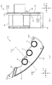
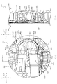
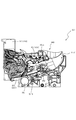
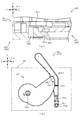
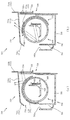
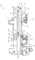
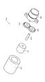
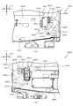
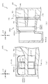
次いで、図21から図24を参照して第1受入部561から第1ユニット551の内部に流入する遊技球の送球経路について説明する。図21は、図18(b)のXXI−XXI線における第1ユニット551の断面図である。図22は、図21に示す第1ユニット551の模式断面図である。図23は、図18(b)のXXIII−XXIII線における第1ユニット551の断面図である。図24(a)は、図21のXXIVa−XXIVa線における第1ユニット551の断面図であり、図24(b)は、図21のXXIVb−XXIVb線における第1ユニット551の断面図であり、図24(c)は、図21のXXIVc−XXIVc線における第1ユニット551の断面図である。   Next, with reference to FIG. 21 to FIG. 24, a description will be given of the pitch of a game ball that flows from the first receiving portion 561 into the first unit 551. FIG. 21 is a cross-sectional view of the first unit 551 taken along line XXI-XXI in FIG. FIG. 22 is a schematic cross-sectional view of the first unit 551 shown in FIG. FIG. 23 is a cross-sectional view of the first unit 551 taken along line XXIII-XXIII in FIG. 24A is a cross-sectional view of the first unit 551 along the line XXIVa-XXIVa in FIG. 21, and FIG. 24B is a cross-sectional view of the first unit 551 along the line XXIVb-XXIVb in FIG. FIG. 24C is a cross-sectional view of the first unit 551 taken along line XXIVc-XXIVc in FIG.

なお、第1ユニット内部に流入する遊技球は、遊技球の主経路SK1〜SK6を主経路SK1、主経路SK2、主経路SK3、主経路SK4、主経路SK5、主経路SK6の順に流下する。又は、主経路SK1〜SK6を流下する途中の主経路SK3から主経路SK3に連通する副経路HK1に流入されて副経路HK1を流下する。もしくは、主経路SK1〜主経路SK6を流下する途中の主経路SK5から主経路SK5に連通する副経路HK2又は副経路HK3のどちらかに流入されて副経路HK2又は副経路HK3のどちらかを流下する。   The game balls that flow into the first unit flow down the main paths SK1 to SK6 of the game balls in the order of the main path SK1, the main path SK2, the main path SK3, the main path SK4, the main path SK5, and the main path SK6. Or, it flows into the sub route HK1 communicating with the main route SK3 from the main route SK3 in the middle of flowing down the main routes SK1 to SK6, and flows down the sub route HK1. Or, it flows into either the sub route HK2 or the sub route HK3 communicating with the main route SK5 from the main route SK5 on the way to the main route SK1 to the main route SK6, and flows down either the sub route HK2 or the sub route HK3. To do.

また、副経路HK1〜HK3には、遊技球の通過を検知する検出装置SE3〜SE6が配設されており、その検出装置SE3〜SE6の遊技球の検出により、遊技者に所定の遊技価値が付与される。本実施形態では、所定の球数の賞球により、遊技者に遊技価値が付与される。   The sub-paths HK1 to HK3 are provided with detection devices SE3 to SE6 that detect the passage of a game ball. The detection device SE3 to SE6 detects the game ball, and the player has a predetermined game value. Is granted. In this embodiment, a game value is given to the player by a predetermined number of prize balls.

図21から図24に示すように、主経路SK1は、第1覆設部材581の湾曲部581a及び第2経路部材570の第1転動部576(図24(a)参照)により形成される空間であり、第1開口部571aと第4開口部571dとを連通する。上述したように、湾曲部581aは、第1開口部571a及び第4開口部571d(第2経路部材570)側が開放される断面U字状に湾曲して形成され、主経路SK1を通過する遊技球を背面側に迂回させることができる。これにより、正面視における領域が限られる空間(第1開口部571a又は第4開口部571dの内側を遊技球が通過する際に、遊技球の左右方向における移動量を少なくすることができるので、主経路SK1を通過する遊技球を遊技者に視認させやすくすることができる。これにより、第1ユニット551を通過する遊技球を遊技者に視認させやすくして、遊技者の興趣を高めることができる。   As shown in FIGS. 21 to 24, the main path SK1 is formed by the curved portion 581a of the first covering member 581 and the first rolling portion 576 of the second path member 570 (see FIG. 24A). It is a space and communicates the first opening 571a and the fourth opening 571d. As described above, the curved portion 581a is formed to be curved in a U-shaped cross section in which the first opening 571a and the fourth opening 571d (second path member 570) side are opened, and passes through the main path SK1. The ball can be detoured to the back side. Thereby, since the space in which the region in front view is limited (when the game ball passes inside the first opening 571a or the fourth opening 571d, the amount of movement of the game ball in the left-right direction can be reduced, It is possible to make it easier for the player to visually recognize the game ball passing through the main route SK1, thereby making it easier for the player to visually recognize the game ball passing through the first unit 551, thereby enhancing the interest of the player. it can.

また、後述するように、主経路SK1に流入する遊技球は、遊技者に所定の遊技価値が付与されるので、遊技者に遊技価値が付与される可能性がある遊技球の転動を遊技者に視認させやすくできる。その結果、遊技者に興趣を与えやすくすることができる。なお、主経路SK1は、後述する主経路SK2と連通されており、主経路SK1を通過する遊技球を主経路SK2に流入させることができる。   In addition, as will be described later, the game ball that flows into the main route SK1 is given a predetermined game value to the player, so that it is possible to play the rolling of the game ball that may give the game value to the player. It can be made easy to visually recognize. As a result, it is possible to make it easier to give the player interest. The main route SK1 communicates with a main route SK2 described later, and a game ball passing through the main route SK1 can flow into the main route SK2.

また、主経路SK1の湾曲部581aは、上述したセンターフレーム86の凹部86b2(図17参照)に収容されて配設される。これにより、主経路SK1に遊技球が詰まった(流れが遅い)場合に、その不具合を検出装置86b3(図17参照)により検出して、エラーを報知することができる。   Further, the curved portion 581a of the main path SK1 is accommodated and disposed in the concave portion 86b2 (see FIG. 17) of the center frame 86 described above. Thereby, when the game ball is clogged in the main route SK1 (the flow is slow), the malfunction can be detected by the detection device 86b3 (see FIG. 17) and an error can be notified.

さらに、主経路SK1の通路幅は、遊技球の直径よりも若干大きく設定されると共に、検出装置SE3〜SE7(図23参照)の遊技球が通過する開口よりも小さく設定される。これにより、基準の遊技球の直径(11ミリメートル)よりも直径の大きい遊技球(不正な遊技球)が製造されて、その球で不正(遊技)が行われた場合に、その球を主経路SK1の内側に留めることができる。よって、不正な遊技球が、主経路SK1の下流側に配設される検出装置SE3〜SE7に流下して不正が行われることを抑制できる。また、不正な遊技球を主経路SK1に留めることで、検出装置86b3(図17参照)により検出して、エラー(不正)を報知することができる。なお、この場合の不正とは、検出装置SE3〜SE7のいずれかの開口に不正な遊技球を嵌めて、検出装置SE3〜SE7に検出を継続させて、不正な遊技球の払い出し(遊技価値)を得ることである。   Furthermore, the passage width of the main route SK1 is set to be slightly larger than the diameter of the game ball and set to be smaller than the opening through which the game ball of the detection devices SE3 to SE7 (see FIG. 23) passes. As a result, when a game ball (illegal game ball) having a diameter larger than the diameter (11 mm) of the reference game ball is manufactured, and the ball is illegal (game), the ball passes through the main path. It can be fastened inside SK1. Therefore, it is possible to suppress illegal game balls from flowing down to the detection devices SE3 to SE7 disposed on the downstream side of the main route SK1 and performing fraud. Further, by stopping the illegal game ball on the main route SK1, it is possible to detect the error (injustice) by detecting it by the detection device 86b3 (see FIG. 17). In this case, fraud means that an illegal game ball is fitted into one of the openings of the detection devices SE3 to SE7, and the detection devices SE3 to SE7 are allowed to continue detection to pay out the illegal game ball (game value). Is to get.

主経路SK2は、第1経路部材560の第1壁部565と、第2経路部材570の第4壁部573との間に形成される空間である。主経路SK2に流入される遊技球は、第4壁部573の上面を転動して流下される。上述したように、第4壁部573は、左右方向(矢印L−R方向)に延設され第4開口部571dから離間するにつれて下降傾斜して形成される。   The main path SK2 is a space formed between the first wall part 565 of the first path member 560 and the fourth wall part 573 of the second path member 570. The game ball flowing into the main path SK2 rolls down on the upper surface of the fourth wall portion 573. As described above, the fourth wall portion 573 extends in the left-right direction (the direction of the arrow LR) and is formed to be inclined downward as it is separated from the fourth opening portion 571d.

従って、上述した湾曲部581a(背面側への湾曲経路)は、遊技球の送球方向の切り替え部分(主経路SK1と主経路SK2との連結部分)に形成されるので、遊技者が、主経路SK1を流下する遊技球を見失うことを抑制できる。即ち、左右方向に延びる直線状の送球経路(例えば、主経路SK2)の途中に背面側に湾曲する経路が形成される場合には、その湾曲する経路で一定の加速度で転動する遊技球の加速度が変化される(小さくなる)ので、遊技球を追っていた目線が遊技球よりも先行してしまうことで、遊技者が遊技球を見失う恐れがある。   Therefore, the above-described bending portion 581a (curving path toward the back side) is formed at a switching portion (a connecting portion between the main path SK1 and the main path SK2) of the game ball in the direction in which the game ball is sent. Loss of sight of game balls flowing down SK1 can be suppressed. That is, when a path that curves to the back side is formed in the middle of a linear ball-feeding path that extends in the left-right direction (for example, the main path SK2), the gaming ball that rolls at a constant acceleration along the curved path. Since the acceleration is changed (decreased), there is a possibility that the player loses sight of the game ball because the line of sight following the game ball precedes the game ball.

これに対し、遊技球の転動方向が切り替えられて本来遊技球の転動速度が遅くされる部分に背面側への湾曲経路を形成するので、遊技者の目線が遊技球よりも先行することを抑制して、遊技者が遊技球を見失うことを抑制できる。   On the other hand, since the rolling direction of the game ball is switched and a curved path to the back side is formed at a portion where the rolling speed of the game ball is originally slowed down, the player's eyes must precede the game ball. It is possible to suppress the player from losing sight of the game ball.

また、主経路SK1の内壁である湾曲部581aは、遊技盤13の左右方向中央部に対して若干右方(矢印R方向)に配設される第1ユニット551の正面視左側(矢印L方向側の端部)に形成される。よって、遊技盤13の正面に位置する遊技者から第1ユニット551を視認しやすい側に、背面側への湾曲経路(主経路SK1)が形成されるので、遊技者が主経路SK1から主経路SK2を通過する遊技球を見失うことを抑制しやすくできる。   Further, the curved portion 581a that is the inner wall of the main path SK1 is the left side (in the direction of the arrow L) of the first unit 551 that is disposed slightly to the right (in the direction of the arrow R) with respect to the central portion in the left-right direction of the game board 13. Side end). Therefore, a curved path (main path SK1) to the back side is formed on the side where the first unit 551 is easily visible from the player located in front of the game board 13, so that the player can move from the main path SK1 to the main path. It is easy to suppress losing sight of the game ball passing through SK2.

また、主経路SK2は、湾曲経路WK1に連通されており、湾曲経路WK1を介して、後述する主経路SK3と連通される。これにより、主経路SK2を通過する遊技球は、湾曲経路WK1を介して、主経路SK3に流入される。なお、湾曲経路WK1についての詳しい説明は後述する。   The main route SK2 communicates with the curved route WK1, and communicates with a later-described main route SK3 via the curved route WK1. Thereby, the game ball passing through the main route SK2 flows into the main route SK3 via the curved route WK1. A detailed description of the curved path WK1 will be described later.

主経路SK3は、第2経路部材570の第4壁部573と、第5壁部574との間に形成される空間である。主経路SK3に流入される遊技球は、第5壁部574の上面を転動して流下される。また、主経路SK3には、上述した第1駆動ユニット583の第1可変板583bが張出時に主経路SK3上に突出される。この主経路SK3上に第1可変板583bが突出した状態では、第5壁部574の上部を転動する遊技球が、第1可変板583bの上面を転動して主経路SK4に送球される。   The main path SK3 is a space formed between the fourth wall part 573 and the fifth wall part 574 of the second path member 570. The game balls that flow into the main path SK3 roll down on the upper surface of the fifth wall portion 574. In the main path SK3, the first variable plate 583b of the first drive unit 583 described above protrudes on the main path SK3 when protruding. In a state where the first variable plate 583b protrudes on the main path SK3, the game ball rolling on the upper portion of the fifth wall portion 574 rolls on the upper surface of the first variable plate 583b and is sent to the main path SK4. The

一方、主経路SK3上から第1可変板583bが退避した状態では、第5壁部574に形成される第1受入凹部574a及び第2受入凹部574bの内部に形成される空間の副経路HK1に遊技球が流入される。副経路HK1は、第5開口部571eを介して背面側壁部582bにより形成される回収経路に送球される。   On the other hand, in a state in which the first variable plate 583b is retracted from the main path SK3, the sub-path HK1 of the space formed inside the first receiving recess 574a and the second receiving recess 574b formed in the fifth wall portion 574. A game ball is introduced. The sub route HK1 is sent to the collection route formed by the back side wall portion 582b through the fifth opening 571e.

この様に、第1ユニット551は、遊技球の送球経路上に張り出し、又は、送球経路上から退避する第1可変板583bを備え、第1可変板583bの変位により、第1ユニット551の主経路SK3を流下する遊技球が副経路HK1に案内される場合と、主経路SK4に案内される場合と、に変更することができるので、第1ユニット551を流下する遊技球の流下方向に変化を与えることができる。   As described above, the first unit 551 includes the first variable plate 583b that protrudes from or retracts from the pitching path of the game ball, and the main unit of the first unit 551 is displaced by the displacement of the first variable plate 583b. Since the game ball flowing down the route SK3 can be changed to the case where the game ball is guided to the sub route HK1 and the case where the game ball is guided to the main route SK4, the game ball flowing down the first unit 551 changes in the flow direction. Can be given.

この場合、副経路HK1に流入する遊技球は、遊技者に所定の遊技価値が付与されるので、遊技者に、遊技球が副経路HK1に流入したかどうかを注視させることができる。また、第1可変板583bは、第1ユニット551に形成される送球経路の途中に配置され、遊技者の視認方向(矢印F−B方向)に変位されるので、遊技者から第1可変板583bの変位を視認させにくくすることができる。その結果、第1ユニット551の流下する遊技球に注視させることができ、遊技者に遊技球の流下による興趣を与えやすくできる。   In this case, the game ball that flows into the sub route HK1 is given a predetermined game value to the player, so that the player can watch whether the game ball has flowed into the sub route HK1. Further, the first variable plate 583b is disposed in the middle of the pitching path formed in the first unit 551, and is displaced in the player's visual recognition direction (arrow FB direction). The displacement of 583b can be made difficult to visually recognize. As a result, the game balls flowing down by the first unit 551 can be watched, and the player can be easily given interest by the flow of game balls.

また、副経路HK1は、正面視において遊技球を右側(矢印R方向側)から左側(矢印L方向側)に送球する主経路SK3と、その主経路SK3の下方に位置し遊技球を左側から右側に送球する主経路SK6との間を形成する第5壁部574に形成される。従って、副経路HK1は、遊技球を左右に送球させる間の空間を利用して形成されるので、第1ユニット551の外形が上下方向に大きくなることを抑制できる。その結果、第1ユニット551の外形を小さくすることで、遊技者が遊技球を目で追う範囲を狭めることができ、遊技者に第1ユニット551を流下する遊技球を視認させやすくすることができる。   In addition, the sub route HK1 is a main route SK3 for sending a game ball from the right side (arrow R direction side) to the left side (arrow L direction side) when viewed from the front, and a lower side of the main route SK3 and the game ball from the left side. It is formed in the 5th wall part 574 which forms between main path | route SK6 which pitches to the right side. Therefore, since the sub route HK1 is formed using the space between the game balls being sent left and right, it is possible to prevent the outer shape of the first unit 551 from increasing in the vertical direction. As a result, by reducing the outer shape of the first unit 551, the range in which the player can follow the game ball with his eyes can be narrowed, and the player can easily see the game ball flowing down the first unit 551. it can.

主経路SK4は、凹設部571gと第1経路部材560の突起568とにより形成される空間である。主経路SK4に流入する遊技球は、突起568に当接して凹設部571gの内側(背面側)に送球された後に、凹設部の内面に沿って突起568の周囲を転動して凹設部の外側(正面側)に送球される。即ち、遊技球は、突起568を迂回するように転動される。また、主経路SK4は、主経路SK5に連通されており、主経路SK4を通過する遊技球を主経路SK5に流入させることができる。   The main path SK4 is a space formed by the recessed portion 571g and the protrusion 568 of the first path member 560. The game ball flowing into the main path SK4 contacts the protrusion 568 and is sent to the inside (rear side) of the recessed portion 571g, and then rolls around the protrusion 568 along the inner surface of the recessed portion. The ball is sent to the outside (front side) of the installation part. That is, the game ball is rolled so as to bypass the protrusion 568. The main route SK4 communicates with the main route SK5, and a game ball passing through the main route SK4 can flow into the main route SK5.

主経路SK5は、上述した第3経路部材580の第2覆設部材582の第1空間582a2及び第2空間582a3により形成される空間である。主経路SK5に流入される遊技球は、上述したように第1空間582a2の内部を背面側に転動した後に、第2空間582a3の内部を正面側に転動される。また、主経路SK5には、上述した第2駆動ユニット584の第2可変板584bが張出時に主経路SK5上に突出する。この主経路SK5上に第2可変板584bが突出した状態では、第2湾曲部582aの内部を転動する遊技球が、主経路SK6に送球される。   The main path SK5 is a space formed by the first space 582a2 and the second space 582a3 of the second covering member 582 of the third path member 580 described above. As described above, the game ball flowing into the main path SK5 rolls inside the first space 582a2 to the back side and then rolls inside the second space 582a3 to the front side. In the main path SK5, the second variable plate 584b of the second drive unit 584 described above projects on the main path SK5 when protruding. In a state where the second variable plate 584b protrudes on the main path SK5, a game ball that rolls inside the second bending portion 582a is sent to the main path SK6.

一方、主経路SK5上から第2可変板584bが退避した状態では、第6壁部575に形成される第3受入凹部575a及び第4受入凹部575bの内部に形成される空間の副経路HK2に遊技球が流下される。副経路HK2は、第6開口部571fを介して背面側壁部582bにより形成される回収経路に送球される。   On the other hand, in a state in which the second variable plate 584b is retracted from the main path SK5, the second receiving plate HK2 is formed in the third receiving recess 575a and the fourth receiving recess 575b formed in the sixth wall 575. A game ball flows down. The sub route HK2 is sent to the collection route formed by the back side wall portion 582b through the sixth opening 571f.

また、主経路SK5を構成する第2湾曲部582aは、上述したように背面側に湾曲して形成されており、主経路SK5を通過する遊技球を背面側に迂回させることができる。これにより、正面視における領域が所定の限られた空間に設定される場合でも、遊技球が転動可能な距離を長くすることができる。   Further, as described above, the second bending portion 582a configuring the main route SK5 is formed to bend toward the back side, and the game ball passing through the main route SK5 can be detoured toward the back side. Thereby, even when the area | region in front view is set to the predetermined limited space, the distance which a game ball can roll can be lengthened.

さらに、第2可変板584bは、主経路SK5の上流側の一部と、主経路SK5の下流側の一部とで張出し、又は、退避の変位がされるように構成され、それら主経路SK5の上流側と主経路SK5の下流側との間に背面側への湾曲経路が形成されるので、主経路SK5を通過する遊技球により遊技者に遊技価値が付与される可能性がある時間を長くできる。その結果、遊技者に興趣を与える時間を長くすることができる。   Further, the second variable plate 584b is configured to project or retreat with a part of the upstream side of the main path SK5 and a part of the downstream side of the main path SK5, and the main path SK5. Since a curved path toward the back side is formed between the upstream side of the main path SK5 and the downstream side of the main path SK5, the game ball passing through the main path SK5 has a time during which there is a possibility that game value may be given to the player. Can be long. As a result, it is possible to lengthen the time for providing the player with interest.

主経路SK4と主経路SK5との連通部分には、副経路HK3が連通される。副経路HK3は、第1経路部材560の第2壁部566と、第3経路部材580の背面側壁部584c1との対向間に形成される空間である。   The sub route HK3 communicates with the communication portion between the main route SK4 and the main route SK5. The sub route HK3 is a space formed between the second wall portion 566 of the first route member 560 and the back side wall portion 584c1 of the third route member 580.

副経路HK3は、主経路SK4から主経路SK5に遊技球が流入した際の遊技球の流下方向(正面視右方向(矢印R方向)と異なる方向(正面視左方向(矢印L方向))に開口される。また、副経路HK3は、その流入口の下側内縁が第2可変板584bよりも下方(矢印D方向)に設定される。   The sub route HK3 is in a direction different from the flow direction of the game ball when the game ball flows from the main route SK4 into the main route SK5 (right direction in front view (arrow R direction)) (left direction in front view (arrow L direction)). In addition, the lower inner edge of the inflow port of the sub route HK3 is set below (in the direction of arrow D) below the second variable plate 584b.

ここで、遊技球が主経路SK4から主経路SK5に正常に(重力以外の外力が作用しない状態で)流下する場合には、主経路SK4から主経路SK5又は副経路HK2に遊技球が流入される。一方、遊技球が主経路SK4から副経路HK2に流入するタイミングで第2可変板584bが張出されて第2可変板584bの先端面と遊技球が当接して、遊技球に重力以外の外力が作用した場合には、第2可変板584bにより副経路HK3の流入口に遊技球が押し出されて副経路HK3に流入される。   Here, when the game ball normally flows from the main route SK4 to the main route SK5 (in a state where an external force other than gravity does not act), the game ball flows into the main route SK5 or the sub route HK2. The On the other hand, when the game ball flows from the main path SK4 into the sub-path HK2, the second variable plate 584b is extended and the front surface of the second variable plate 584b comes into contact with the game ball, so that an external force other than gravity is applied to the game ball. When the action is applied, the game ball is pushed out to the inlet of the sub route HK3 by the second variable plate 584b and flows into the sub route HK3.

よって、第1ユニット551は、遊技球の送球経路上に張り出し、又は、送球経路上から退避する第2可変板584bを備え、第2可変板584bの変位により、第1ユニット551の主経路SK4又は主経路SK5を流下する遊技球が主経路SK5、副経路HK2又は副経路HK3のいずれかに案内されるので、第1ユニット551を流下する遊技球の流下方向に変化を与えることができる。   Therefore, the first unit 551 includes the second variable plate 584b that protrudes or retreats from the pitching path of the game ball, and the main path SK4 of the first unit 551 is displaced by the displacement of the second variable plate 584b. Alternatively, the game ball flowing down the main route SK5 is guided to any one of the main route SK5, the sub route HK2, and the sub route HK3, so that it is possible to change the flow direction of the game ball flowing down the first unit 551.

この場合、副経路HK2又は副経路HK3に流入する遊技球により遊技者に所定の遊技価値が付与されるので、遊技者に、遊技球が副経路HK2又は副経路HK3に流入したかどうかを注視させることができる。また、第2可変板584bは、第1ユニット551に形成される送球経路の途中に配置されるので、遊技者から板部材584b2の変位を視認させにくくすることができる。その結果、第1ユニット551を流下する遊技球に注視させることができ、遊技者に遊技球の流下による興趣を与えやすくできる。   In this case, since a predetermined game value is given to the player by the game ball flowing into the sub route HK2 or the sub route HK3, it is noted whether the game ball has flowed into the sub route HK2 or the sub route HK3. Can be made. In addition, since the second variable plate 584b is arranged in the middle of the pitching path formed in the first unit 551, it is possible to make it difficult for the player to visually recognize the displacement of the plate member 584b2. As a result, the game balls flowing down the first unit 551 can be watched, and the player can be easily given interest by the flow of game balls.

また、上述したように、主経路SK4を挟んで上流側では、第1可変板583bにより、遊技球の流下する経路が切り替えられる。よって、上流側の副経路HK1に流入せず遊技者に遊技価値が付与されていない遊技球をさらに下流に流下させて副経路HK2又はHK3に流入させることができる。従って、遊技者に遊技価値が一度付与される可能性があった遊技球を流下経路の切り替え部分を通過させることで、遊技球が副経路HK2及びHK3に流入する願望を遊技者に再度持たせることができる。   Further, as described above, on the upstream side of the main route SK4, the route through which the game ball flows down is switched by the first variable plate 583b. Therefore, a game ball that does not flow into the upstream side sub route HK1 and is not given game value to the player can flow further downstream and flow into the sub route HK2 or HK3. Therefore, by passing the game ball that may have been given game value to the player once through the switching part of the flow-down path, the player has the desire to flow into the sub-paths HK2 and HK3 again. be able to.

さらに、遊技球の流下する経路が切り替えられる主経路SK3と主経路SK5との間には、背面側に湾曲する主経路SK4が配設される。従って、正面視における所定の範囲内で遊技球を転動させることができ、遊技者に遊技球の位置を認識させやすくできる。即ち、主経路SK3を流下した後に、主経路SK4を通して遊技球の位置を遊技者に認識させることで、主経路SK4の下流に連結される主経路SK5を転動する遊技球を遊技者に注視させやすくできる。その結果、遊技球が副経路HK2及びHK3に流入する遊技球を遊技者に視認させやすくでき、遊技者の興趣を向上できる。   Further, a main path SK4 that is curved to the back side is disposed between the main path SK3 and the main path SK5 where the path of the game ball is switched. Therefore, the game ball can be rolled within a predetermined range in front view, and the player can easily recognize the position of the game ball. That is, after flowing down the main route SK3, the player recognizes the position of the game ball through the main route SK4, so that the player pays attention to the game ball rolling on the main route SK5 connected downstream of the main route SK4. It can be made easy. As a result, it is easy for the player to visually recognize the game balls in which the game balls flow into the sub-paths HK2 and HK3, and the player's interest can be improved.

また、第2可変いた584bの正面側の左右の両端部には、左右方向の端部に向かう程、背面側に傾斜する傾斜面584b1(図24(c)参照)が形成される。これにより、遊技球が主経路SK4から副経路HK2に流入するタイミングで第2可変板584bが張出されて第2可変板584bの先端面と遊技球とが当接した際に、傾斜面584b1により遊技球を副経路HK3の流入口側に押し出すことができる。従って、傾斜面584b1及び副経路HK2により第2可変板584bと第1経路部材560との間に遊技球が挟まることを防止することができると共に、遊技球が流下されるタイミングの違いにより流下方向が切り替えられる経路を複数(本実施形態では3経路)形成することができる。   In addition, inclined surfaces 584b1 (see FIG. 24C) that are inclined toward the back side are formed at the left and right end portions on the front side of the second variable 584b toward the ends in the left-right direction. As a result, when the second variable plate 584b is extended at the timing when the game ball flows from the main route SK4 into the sub route HK2, and the tip surface of the second variable plate 584b comes into contact with the game ball, the inclined surface 584b1. Thus, the game ball can be pushed out to the inlet side of the sub route HK3. Accordingly, it is possible to prevent the game ball from being sandwiched between the second variable plate 584b and the first route member 560 by the inclined surface 584b1 and the sub route HK2, and in the flow down direction due to the difference in timing at which the game ball flows down. A plurality of paths (three paths in the present embodiment) can be formed.

主経路SK6は、第1経路部材560の第3壁部567で囲われる空間である。主経路SK6を流下する遊技球は、遊技盤13の遊技領域に送球される。従って、第1受入部561に流入した遊技球が、第1受入凹部574a〜第4受入凹部575bに流入されない場合には、遊技者に遊技価値が付与されず、主経路SK6から遊技盤13の遊技領域に送球されて、遊技盤13に形成されるアウト口71から回収される。   The main path SK6 is a space surrounded by the third wall portion 567 of the first path member 560. The game balls flowing down the main route SK6 are sent to the game area of the game board 13. Therefore, when the game ball that has flowed into the first receiving portion 561 is not flowed into the first receiving recess 574a to the fourth receiving recess 575b, no game value is given to the player, and the game board 13 is connected from the main path SK6. The ball is sent to the game area and collected from the out port 71 formed in the game board 13.

<遊技球を前後方向に変位させる案内手段>
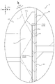
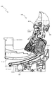
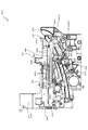
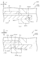
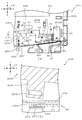
次いで、図25から図28を参照して、主経路SK2から主経路SK3への遊技球の流下について説明する。図25(a)及び図26(a)は、図21の範囲XXVaにおける第1ユニット551の部分拡大図であり、図25(b)及び図26(b)は、図25(a)のXXVb−XXVb線における第1ユニット551の断面図である。図27(a)は、図25(a)のXXVIIa−XXVIIa線における第1ユニット551の模式断面図であり、図27(b)は、図25(a)のXXVIIb−XXVIIb線における第1ユニット551の模式断面図であり、図27(c)は、図25(a)のXXVIIc−XXVIIc線における第1ユニット551の模式断面図である。図28(a)は、図25(a)のXXVb−XXVb線における第1ユニット551の模式断面図であり、図28(b)は、図25(a)のXXVIIIb−XXVIIIb線における第1ユニット551の模式断面図である。なお、図26では、湾曲経路WK1を流下する遊技球が図示される。
<Guide means for displacing the game ball in the front-rear direction>
Next, with reference to FIGS. 25 to 28, the flow of the game ball from the main route SK2 to the main route SK3 will be described. FIGS. 25A and 26A are partially enlarged views of the first unit 551 in the range XXVa of FIG. 21, and FIGS. 25B and 26B are XXVb of FIG. 25A. It is sectional drawing of the 1st unit 551 in the -XXVb line. 27A is a schematic cross-sectional view of the first unit 551 along the line XXVIIa-XXVIIa in FIG. 25A, and FIG. 27B is the first unit along the line XXVIIb-XXVIIb in FIG. FIG. 27C is a schematic cross-sectional view of the first unit 551 along the line XXVIIc-XXVIIc in FIG. FIG. 28A is a schematic cross-sectional view of the first unit 551 along the line XXVb-XXVb in FIG. 25A, and FIG. 28B is the first unit along the line XXVIIIb-XXVIIIb in FIG. 5 is a schematic cross-sectional view of 551. FIG. In FIG. 26, a game ball flowing down the curved path WK1 is shown.

図25から図28に示すように、主経路SK2、主経路SK3及び湾曲経路WK1は、第2経路部材570のベース板571に、背面側に向かって断面円弧状に凹設される第1凹部571h、第2凹部571i及び第3凹部571jと、主経路SK2上の内壁から正面側に階段状に突出する第1段部571kと、主経路SK3上の内壁から階段状に突出する第2段部571mと、を備える。   As shown in FIGS. 25 to 28, the main path SK2, the main path SK3, and the curved path WK1 are formed in the base plate 571 of the second path member 570 as a first recess recessed in an arc shape in cross section toward the back side. 571h, second recess 571i and third recess 571j, a first step 571k protruding stepwise from the inner wall on the main path SK2 to the front side, and a second step protruding stepwise from the inner wall on the main path SK3 Part 571m.

第1経路部材560の正面板564は、第1凹部571h、第2凹部571i及び第3凹部571jと対向する位置に、それぞれ第1凸部564b、第2凸部564c及び第3凸部564dが突設される。   The front plate 564 of the first path member 560 has a first convex portion 564b, a second convex portion 564c, and a third convex portion 564d at positions facing the first concave portion 571h, the second concave portion 571i, and the third concave portion 571j, respectively. Projected.

第2凹部571iと第2凸部564cとの対向間寸法L11(図28(a)参照)は、遊技球の直径よりも大きい値に設定されると共に、正面板564及びベース板571の対向間の距離寸法L12(図28(a)参照)よりも小さい値に設定される。これにより、第1凹部571h、第2凹部571i及び第3凹部571jと、第1凸部564b、第2凸部564c及び第3凸部564dとの対向間に送球される遊技球を第1凹部571h、第2凹部571i及び第3凹部571jと、第1凸部564b、第2凸部564c及び第3凸部564dに当接させて、遊技球の転動(流下)速度を遅くすることができる。   The facing dimension L11 (see FIG. 28 (a)) between the second concave portion 571i and the second convex portion 564c is set to a value larger than the diameter of the game ball, and the facing distance between the front plate 564 and the base plate 571. Is set to a value smaller than the distance dimension L12 (see FIG. 28A). Thereby, the first concave portion 571h, the second concave portion 571i, the third concave portion 571j, and the game ball sent between the first convex portion 564b, the second convex portion 564c, and the third convex portion 564d are opposed to the first concave portion. 571h, the second concave portion 571i and the third concave portion 571j, and the first convex portion 564b, the second convex portion 564c, and the third convex portion 564d are brought into contact with each other to slow down the rolling (downflow) speed of the game ball. it can.

また、第1凹部571h及び第1凸部564bの対向間寸法と、第3凹部571j及び第3凸部564dの対向間寸法とは、第2凹部571iと第2凸部564cとの対向間寸法L11と略同一の距離に設定される。   Further, the dimension between the first concave part 571h and the first convex part 564b and the dimension between the third concave part 571j and the third convex part 564d are the dimension between the second concave part 571i and the second convex part 564c. The distance is set substantially the same as L11.

さらに、第1凸部564b、第2凸部564c及び第3凸部564dの突設先端面と、第1凹部571h、第2凹部571i及び第3凹部571jを除くベース板571の正面との対向間の距離寸法L13(図28(a)参照)は、遊技球の直径よりも小さく設定される。これにより、第1凹部571h、第2凹部571i及び第3凹部571jと、第1凸部564b、第2凸部564c及び第3凸部564dとの対向間に送球される遊技球を第1凸部564b、第2凸部564c及び第3凸部564dに衝突させることができる。その結果、遊技球の転動(流下)速度を遅くすることができる。   Further, the protruding front end surfaces of the first convex portion 564b, the second convex portion 564c, and the third convex portion 564d are opposed to the front surface of the base plate 571 excluding the first concave portion 571h, the second concave portion 571i, and the third concave portion 571j. The distance dimension L13 (see FIG. 28A) is set smaller than the diameter of the game ball. Thereby, the game balls sent between the first concave portion 571h, the second concave portion 571i and the third concave portion 571j, and the first convex portion 564b, the second convex portion 564c and the third convex portion 564d are opposed to the first convex portion. It can be made to collide with the part 564b, the 2nd convex part 564c, and the 3rd convex part 564d. As a result, the rolling (downflow) speed of the game ball can be reduced.

また、この場合、第1凸部564b、第2凸部564c及び第3凸部564dに当接した遊技球は、第1凹部571h、第2凹部571i及び第3凹部571jの内側を流下される。従って、流下する遊技球を第1凹部571h、第2凹部571i及び第3凹部571jの凹設方向に案内することができる。   Further, in this case, the game balls that are in contact with the first convex portion 564b, the second convex portion 564c, and the third convex portion 564d flow down inside the first concave portion 571h, the second concave portion 571i, and the third concave portion 571j. . Accordingly, it is possible to guide the flowing game ball in the direction in which the first recess 571h, the second recess 571i, and the third recess 571j are provided.

段部571kは、主経路SK2の背面側の内壁から正面側に突出される。また、段部571kは、主経路SK2の経路内における下流側に形成される。段部571kは、主経路SK2の上流側の端部が、ベース板571の正面から正面側に突出した位置に設定されると共に、下流側の端部が彎曲経路WK1の背面と同一の位置に設定される。これにより、主経路SK2を流下する遊技球を、段部571kに当接させて、正面側に移動させることができる。   The step portion 571k protrudes to the front side from the inner wall on the back side of the main path SK2. Further, the step portion 571k is formed on the downstream side in the main route SK2. The stepped portion 571k is set such that the upstream end of the main path SK2 protrudes from the front surface of the base plate 571 to the front side, and the downstream end is located at the same position as the back surface of the curved path WK1. Is set. Thereby, the game ball flowing down the main route SK2 can be brought into contact with the stepped portion 571k and moved to the front side.

また、段部571kは、上流側の端部が上流側から下流側に向かって正面側に突出する傾斜面として形成される。これにより、主経路SK2を流下して段部571kの上流側の端部に当接する遊技球を正面側に案内しつつ下流側に流下させることができる。   Further, the step portion 571k is formed as an inclined surface in which an upstream end projects from the upstream side toward the downstream side toward the front side. As a result, the game ball that flows down the main path SK2 and comes into contact with the upstream end of the stepped portion 571k can flow down to the downstream side while being guided to the front side.

さらに、段部571kは、上流側の端部が、正面板564に形成される第1凸部564bよりも主経路SK2の上流側に形成される。これにより、段部571kに当接して正面側に案内される遊技球を第1凸部564bに当接させやすくすることができる。   Furthermore, the step portion 571k has an upstream end formed on the upstream side of the main path SK2 with respect to the first convex portion 564b formed on the front plate 564. Thereby, it is possible to make it easier for the game ball guided to the front side to come into contact with the step portion 571k to come into contact with the first convex portion 564b.

第1凹部571hは、主経路SK2を構成するベース板571に凹設されており、正面視において、水平方向(矢印L−R方向)に長い楕円形状に形成される。また、第1凹部571hは、段部571kにより正面側に突出された位置におけるベース板571に形成される。第1凹部571hの上下方向の中心における背面側への凹設深さは、段部571kの正面側への高さ寸法L22(図27(b)参照)と、略同一に設定される。これにより、暴れずに主経路SK2を送球される遊技球を、第1凹部571hの凹設方向(背面側(矢印B方向側)に変位させなくても、第1凹部571hの内側に流入させることができる。   The first recess 571h is recessed in the base plate 571 constituting the main path SK2, and is formed in an elliptical shape that is long in the horizontal direction (arrow LR direction) when viewed from the front. The first recess 571h is formed in the base plate 571 at a position protruding to the front side by the step 571k. The depth of the recess on the back side at the center in the vertical direction of the first recess 571h is set to be substantially the same as the height dimension L22 (see FIG. 27B) on the front side of the step 571k. Accordingly, the game ball that is sent through the main path SK2 without being violated is allowed to flow inside the first recess 571h without being displaced in the concave direction of the first recess 571h (back side (arrow B direction side)). be able to.

一方、暴れた状態で主経路SK2を送球される遊技球は、段部571kの上流側の端部に当接させて、主経路SK2の正面側に案内して、正面板564の第1凸部564bに当接させる。これにより、遊技球の暴れを抑制しつつ、遊技球を第1凹部571hの内側に送球することができる。   On the other hand, the game ball sent on the main route SK2 in a violent state is brought into contact with the upstream end of the step portion 571k, guided to the front side of the main route SK2, and the first protrusion of the front plate 564. It abuts on the part 564b. Thereby, the game ball can be sent to the inside of the first recess 571h while suppressing the rampage of the game ball.

さらに、第1凹部571hは、主経路SK2の上流側における遊技球の転動面(第4壁部573の矢印U方向側の面)から直交する方向の凹設底面までの高さ寸法Y8(図25(a)参照)が遊技球の半径分に設定され、主経路SK2の下流側における遊技球の転動面(第4壁部573の矢印U方向側の面)から直交する方向の凹設底面までの高さ寸法Y9(図25(a)参照)が遊技球の半径分よりも高く設定される。これにより、主経路SK2を流下する遊技球を第1凹部571hに沿って送球する際に、重力方向上側(矢印U方向側)に持ち上がる方向の抵抗を遊技球に作用させて、遊技球の転動速度を小さくすることができる。その結果、湾曲経路WK1に流入する遊技球の転動速度を十分に小さくすることができ、遊技球をスムーズに流下させやすくすることができる。   Further, the first recess 571h is a height dimension Y8 from the rolling surface of the game ball (the surface on the arrow U direction side of the fourth wall portion 573) on the upstream side of the main path SK2 to the recessed bottom surface in the orthogonal direction. FIG. 25 (a)) is set for the radius of the game ball, and the concave in the direction orthogonal to the rolling surface of the game ball (the surface on the arrow U direction side of the fourth wall portion 573) on the downstream side of the main path SK2. A height dimension Y9 (see FIG. 25A) to the installation bottom is set higher than the radius of the game ball. As a result, when the game ball flowing down the main path SK2 is sent along the first recess 571h, a resistance in the direction of lifting upward in the gravitational direction (arrow U direction side) is applied to the game ball so that the game ball is rotated. The moving speed can be reduced. As a result, the rolling speed of the game ball flowing into the curved path WK1 can be made sufficiently small, and the game ball can be made to smoothly flow down.

第1凹部571hの断面における半径X11(図27(b)参照)は、遊技球の半径よりも大きい値に設定されており、第1凹部571hの内側に遊技球が送球された際に、その内壁に遊技球を当接可能とされる。これにより、第1凹部571hと当接する遊技球の当接部分が2箇所になることを抑制して、当接部分が増えることによる遊技球の転動に対する抵抗が大きくなることを抑制できる。その結果、遊技球が主経路SK2で停止することを抑制できる。   The radius X11 (see FIG. 27B) in the cross section of the first recess 571h is set to a value larger than the radius of the game ball, and when the game ball is sent inside the first recess 571h, A game ball can be brought into contact with the inner wall. Thereby, it can suppress that the contact part of the game ball contact | abutted with the 1st recessed part 571h becomes two places, and can suppress that the resistance with respect to rolling of the game ball by the contact part increasing becomes large. As a result, it is possible to prevent the game ball from stopping on the main route SK2.

第1凹部571hと対向する位置に形成される第1凸部564bは、第1凹部571hの上流側の端部から主経路SK2の遊技球の送球方向(図27(b)の矢印R方向)に離間する位置に形成され、その離間する値が遊技球の半径よりも小さい寸法に設定される。これにより、主経路SK2を流下する遊技球を第1凸部564bに当接させて第1凹部571hの内側に送球しやすくできる。   The first convex portion 564b formed at a position facing the first concave portion 571h is the direction in which the game ball is sent from the upstream end of the first concave portion 571h (in the direction of arrow R in FIG. 27B). The distance value is set to a size smaller than the radius of the game ball. Thereby, the game ball flowing down the main path SK2 can be easily brought into contact with the first convex portion 564b and sent inside the first concave portion 571h.

第2凹部571iは、湾曲経路WK1のベース板571に凹設されており、正面視における外形が重力方向(矢印U−D方向)に長い楕円形状に形成される。また、第2凹部571iは、正面視における上下方向(矢印U−D方向)中央位置が、湾曲経路WK1の経路の中間位置に設定される。さらに、第2凹部571iは、正面視における左右方向(矢印L−R方向)中央位置が湾曲経路WK1の送球方向に対して直交する方向の中央位置に形成される。   The second recess 571i is recessed in the base plate 571 of the curved path WK1, and is formed in an elliptical shape whose outer shape in front view is long in the direction of gravity (arrow UD direction). In addition, the second recessed portion 571i is set such that the center position in the vertical direction (arrow UD direction) in the front view is an intermediate position of the curved path WK1. Further, the second concave portion 571i is formed at a central position in a direction where the central position in the left-right direction (arrow LR direction) in the front view is orthogonal to the pitching direction of the curved path WK1.

なお、主経路SK1、湾曲経路WK1及び主経路SK2は、正面視において遊技球の送球方向に対して直交する幅寸法L18(図25(a)参照)がすべて同一の寸法に設定されており、その幅寸法L18が、遊技球の直径の略1.1倍に設定される。   The main path SK1, the curved path WK1, and the main path SK2 are all set to have the same width dimension L18 (see FIG. 25 (a)) perpendicular to the direction in which the game ball is sent in the front view. The width dimension L18 is set to approximately 1.1 times the diameter of the game ball.

また、第1凹部571h、第2凹部571i及び第3凹部571jは、正面視における短手方向の最大の幅寸法が、上述した幅寸法L18の略1/2に設定される。これにより、各経路(主経路SK1、湾曲経路WK1及び主経路SK2)を通過する遊技球の中心を第1凹部571h、第2凹部571i及び第3凹部571jの正面側を通過させることができるので、遊技球を第1凹部571h、第2凹部571i及び第3凹部571jの内側に送球しやすくできる。   Further, the first width of the first recess 571h, the second recess 571i, and the third recess 571j is set to be approximately ½ of the above-described width dimension L18 in the short side direction when viewed from the front. Thereby, the center of the game ball passing through each path (main path SK1, curved path WK1, and main path SK2) can be passed through the front side of the first recess 571h, the second recess 571i, and the third recess 571j. The game balls can be easily fed into the first recess 571h, the second recess 571i, and the third recess 571j.

段部571mは、主経路SK3の背面側の内壁から正面側に突出される。また、段部571mは、主経路SK3の経路内における上流側に形成される。段部571mは、主経路SK3の下流側の端部が、ベース板571の正面側に突出した位置に設定されると共に、上流側の端部が彎曲経路WK1の背面と同一の位置に設定される。これにより、主経路SK3を流下する遊技球が、段部571mよりも下流側に送球された後に、段部571mを超えて上流側に逆流(跳ね返る)することを抑制できる。   The step portion 571m protrudes from the inner wall on the back side of the main path SK3 to the front side. Further, the step portion 571m is formed on the upstream side in the route of the main route SK3. The step 571m is set such that the downstream end of the main path SK3 protrudes to the front side of the base plate 571, and the upstream end is set to the same position as the back of the curved path WK1. The Thereby, it is possible to suppress the game ball flowing down the main route SK3 from flowing back (bounces back) upstream beyond the step portion 571m after being sent downstream from the step portion 571m.

第3凹部571jは、主経路SK3の内壁を構成するベース板571に形成されており、正面視において、水平方向(矢印L−R方向)に長い楕円形状に形成される。また、第3凹部571jは、段部571mにより正面側に突出された位置におけるベース板571に形成される。第3凹部571jの上下方向の中心における背面側への凹設深さは、段部571mの正面側への高さ寸法L23(図27(c)参照)と、略同一に設定される。これにより、主経路KR3を送球される遊技球を、第3凹部571jの内側から外側に流出させやすくできる。   The third recess 571j is formed in the base plate 571 constituting the inner wall of the main path SK3, and is formed in an elliptical shape that is long in the horizontal direction (arrow L-R direction) when viewed from the front. Moreover, the 3rd recessed part 571j is formed in the base board 571 in the position protruded to the front side by the step part 571m. The depth of the recess on the back side at the center of the third recess 571j in the vertical direction is set to be substantially the same as the height L23 (see FIG. 27C) to the front side of the step 571m. Thereby, it is possible to easily cause the game balls sent along the main route KR3 to flow out from the inside to the outside of the third recess 571j.

さらに、主経路SK3の下流側における第3凹部571jの端部は、後述する副経路HK1に流下する経路を切り替える第1可変板583bの主経路SK3の上流側における端部(矢印R方向側の端部)の重力方向上方(矢印U方向)に配置される。これにより、第1可変板583bの停止位置がその変位により重力方向上方にずれた場合(可変板583bが、湾曲壁部565bの下流側端部よりも上方に配置された場合)に、主経路SK3を通過する遊技球を第3凹部571jの内面に沿って送球することで、第1可変板583bに引っ掛かることなく送球できる。その結果、第1壁部565と第1可変板583bとが隣合う部分において、第1可変板583bを下方に配置する必要がなくなり、第1ユニット551の上下方向寸法が大きくなることを抑制できる。   Furthermore, the end of the third recess 571j on the downstream side of the main path SK3 is the end on the upstream side of the main path SK3 of the first variable plate 583b that switches the path that flows down to the sub-path HK1 (described in the direction of the arrow R). It is arrange | positioned in the gravity direction upper direction (arrow U direction) of an edge part. Thereby, when the stop position of the first variable plate 583b is displaced upward in the gravitational direction due to the displacement (when the variable plate 583b is disposed above the downstream end of the curved wall portion 565b), the main path A game ball passing through SK3 is sent along the inner surface of the third recess 571j, so that it can be sent without being caught by the first variable plate 583b. As a result, it is not necessary to dispose the first variable plate 583b below in the portion where the first wall portion 565 and the first variable plate 583b are adjacent to each other, and it is possible to prevent the vertical dimension of the first unit 551 from increasing. .

また、この場合、第3凹部571jは、正面視における長手方向が、水平方向(矢印L−R方向)に形成されており、主経路SK3を流下する遊技球に対して上方に離間されるので、第1壁部565から第1可変板583bに送球される遊技球に対して、上方側に持ち上がる方向の抵抗を作用させることができる。その結果、第1壁部565から第1可変板583bに送球される遊技球が、第1可変板583bに引っ掛かることを抑制できる。   Further, in this case, the third recess 571j is formed in the horizontal direction (arrow LR direction) in the longitudinal direction when viewed from the front, and is separated upward from the game ball flowing down the main path SK3. The resistance in the upward lifting direction can be applied to the game ball sent from the first wall portion 565 to the first variable plate 583b. As a result, it is possible to suppress the game ball sent from the first wall portion 565 to the first variable plate 583b from being caught on the first variable plate 583b.

さらに、第1ユニット551は、正面視における遊技盤13に対して水平方向の一側(矢印R方向側)に遊技球を送球する主経路SK2と、その主経路SK2から送球された遊技球を主経路SK2の案内方向と反対方向の水平方向の他側に送球する主経路SK3と、主経路SK2および主経路SK3の一側同士を連結する湾曲経路WK1と、を備え、湾曲経路WK1は、遊技盤に対して正面側または背面側の少なくとも一方に遊技球を送球する案内手段(第2凸部564c及び第2凹部571i)を遊技盤に対して正面側および背面側の内壁に備えるので、湾曲経路WK1を通過する遊技球を正面側または背面側(正面視における遊技盤13の前後方向)に移動させることができる。   Furthermore, the first unit 551 receives a main path SK2 for sending a game ball to one side in the horizontal direction (arrow R direction side) with respect to the game board 13 in a front view, and a game ball sent from the main path SK2. A main path SK3 that sends a ball to the other side in the horizontal direction opposite to the guide direction of the main path SK2, and a curved path WK1 that connects one side of the main path SK2 and the main path SK3, and the curved path WK1 Since guide means (second convex portion 564c and second concave portion 571i) for sending a game ball to at least one of the front side and the back side with respect to the game board are provided on the inner wall on the front side and the back side with respect to the game board, The game ball passing through the curved path WK1 can be moved to the front side or the back side (the front-rear direction of the game board 13 in the front view).

従って、湾曲経路WK1を通過する遊技球の送球経路が正面視における前後方向に同一の平面に形成される場合よりも、主経路SK2(第1経路)を転動して加速した遊技球の流下速度を遅くすることができる。よって、遊技球の流下速度を遅くできる分、湾曲経路WK1の内壁に衝突した遊技球が主経路SK2に戻る、又は、湾曲経路WK1の内側で主経路SK2の送球方向(正面視における水平方向(矢印L−R方向))に揺れ動く(ぶれる)ことを抑制できる。これにより、湾曲経路WK1を通過する遊技球を遊技者の視線が一定方向に追うことができる。その結果、湾曲経路WK1に送球された遊技球を遊技者に視認させやすくすることができる。   Accordingly, the flow of the game ball accelerated by rolling on the main route SK2 (first route) is more than when the pitch of the game ball passing through the curved route WK1 is formed in the same plane in the front-rear direction in the front view. You can slow down. Therefore, the game ball that collides with the inner wall of the curved path WK1 returns to the main path SK2 by the amount that the flow velocity of the game ball can be slowed down, or the pitching direction of the main path SK2 inside the curved path WK1 (horizontal direction in front view ( (Swaying in the direction of arrow LR))) can be suppressed. Thereby, the player's line of sight can follow the game ball passing through the curved path WK1 in a certain direction. As a result, it is possible to make it easier for the player to visually recognize the game ball sent to the curved path WK1.

また、正面視における遊技盤13に対して遊技球が水平方向(正面視左右方向)に揺れ動く(ぶれる)ことを抑制できるので、その分、主経路SK2および主経路SK3を連結する湾曲経路WK1の経路を長くして遊技球が揺れ動くことを抑制する必要がなくなり、湾曲経路WK1の経路を短くすることができる。その結果、第1ユニット551を遊技盤13に対して所定の領域内に収めることができ、遊技盤13に対する第1ユニット551の配設スペースを確保できる。   In addition, since the game ball can be prevented from swinging (blurring) in the horizontal direction (left-right direction in the front view) with respect to the game board 13 in the front view, the curved path WK1 connecting the main path SK2 and the main path SK3 correspondingly. It is not necessary to lengthen the path and suppress the swinging of the game ball, and the path of the curved path WK1 can be shortened. As a result, the first unit 551 can be stored in a predetermined area with respect to the game board 13, and a space for arranging the first unit 551 with respect to the game board 13 can be secured.

さらに、第1凹部571hは、主経路SK2の上流側に向かって、その主経路SK2の流下方向と直交する方向(矢印U−D方向)に凹設幅が大きくされる。これにより、主経路SK2を流下する遊技球を第1凹部571hに受け入れやすくできる。また、第1凹部571hは、主経路SK2の下流側に向かって、凹設幅が小さく設定されるので、第1凹部571hに受け入れられた遊技球を同じ位置から抜け出させやすい。即ち、第1凹部571hは、主経路SK2の上流側で遊技球を受け入れやすく、主経路SK2の下流側で同じ位置から遊技球を抜け出させやすくできる。その結果、主経路SK2の下流に連通される湾曲経路WK1の第2凹部571iに遊技球を送球しやすくできる。   Furthermore, the first recessed portion 571h has a recessed width that increases in the direction (arrow UD direction) orthogonal to the flow-down direction of the main path SK2 toward the upstream side of the main path SK2. Thereby, the game ball flowing down the main route SK2 can be easily received in the first recess 571h. Further, since the first recessed portion 571h is set to have a smaller recessed width toward the downstream side of the main path SK2, the game ball received in the first recessed portion 571h can be easily pulled out from the same position. That is, the first concave portion 571h can easily receive the game ball on the upstream side of the main route SK2, and can easily escape the game ball from the same position on the downstream side of the main route SK2. As a result, it is possible to easily send the game ball to the second recess 571i of the curved path WK1 communicated downstream of the main path SK2.

この場合、第1凹部571hの主経路SK2の流下方向(矢印R方向)における凹設端部は、主経路SK2を送球される遊技球の転動方向において主経路SK2の転動面(第4壁部573の上面)を超える位置に形成される。従って、第1凹部571hを抜け出る遊技球に、主経路SK2の転動面の影響を受けにくくすることができる。その結果、第1凹部571hから抜け出た遊技球を湾曲経路WK1の第2凹部571iに送球しやすくできる。   In this case, the concave end portion of the first recess 571h in the flow-down direction (arrow R direction) of the main path SK2 is the rolling surface (fourth) of the main path SK2 in the rolling direction of the game ball sent through the main path SK2. It is formed at a position exceeding the upper surface of the wall portion 573. Therefore, it is possible to make the game ball that escapes from the first recess 571h less susceptible to the rolling surface of the main path SK2. As a result, it is possible to easily send the game ball that has escaped from the first recess 571h to the second recess 571i of the curved path WK1.

また、主経路SK2は、第4開口部571d側から湾曲壁部565b側(即ち、正面視左側(矢印L方向側)から正面視右側(矢印R方向側))に向かって、その経路の内部空間が正面板564側(正面側(矢印F方向側))に傾斜して形成される。また、主経路SK2は、その転動面(第4壁部573の重力方向上側の面)が正面側に向かって下降傾斜して形成される。これにより、主経路SK2を流下する遊技球を正面板564側を転動させやすくすることができ、その遊技球を正面板564に形成される第1凸部564bに当接させやすくできる。その結果、第1凸部564bで遊技球の転動速度を遅くさせやすくでき、主経路SK2を流下する遊技球が湾曲壁部565bと衝突した反力で主経路SK2を逆流することを抑制できる。その結果、遊技球の送球方向の変更箇所で遊技球を安定して流下させることができる。   Further, the main path SK2 is located inside the path from the fourth opening 571d side toward the curved wall 565b side (that is, from the front side left side (arrow L direction side) to the front side right side (arrow R direction side)). The space is formed to be inclined toward the front plate 564 side (front side (arrow F direction side)). The main path SK2 is formed such that its rolling surface (the surface on the upper side in the gravity direction of the fourth wall portion 573) is inclined downward toward the front side. Thereby, the game ball flowing down the main path SK2 can be easily rolled on the front plate 564 side, and the game ball can be easily brought into contact with the first convex portion 564b formed on the front plate 564. As a result, it is possible to easily slow down the rolling speed of the game ball with the first convex portion 564b, and it is possible to suppress the game ball flowing down the main route SK2 from flowing back through the main route SK2 due to the reaction force colliding with the curved wall portion 565b. . As a result, it is possible to stably flow down the game ball at the change location of the game ball sending direction.

第2凹部571iは、その上方端部(矢印U方向側端部)が、主経路SK2(第4壁部573)を転動する遊技球の中心の転動軌跡に沿って直線状に描かれる仮想線IL3(図25(a)参照)と接する位置に形成される。これにより、主経路SK2を比較的速い速度で送球されて湾曲経路WK1に流入する遊技球を第2凹部571iに受け入れやすくすることができる。   The second recess 571i has an upper end (end in the arrow U direction) drawn in a straight line along the rolling trajectory at the center of the game ball rolling on the main path SK2 (fourth wall 573). It is formed at a position in contact with the virtual line IL3 (see FIG. 25A). Thereby, it is possible to make it easier for the second concave portion 571i to accept the game ball that is sent through the main route SK2 at a relatively high speed and flows into the curved route WK1.

遊技球の送球方向の変更箇所(湾曲経路WK1)には、第2凹部571i及び第2凸部564cが形成される。上述したように、第1凸部564b、第2凸部564c及び第3凸部564dの突設先端面と、第1凹部571h、第2凹部571i及び第3凹部571jを除くベース板571の正面との対向間の距離寸法L13(図28(a)参照)は、遊技球の直径よりも小さく設定されるので、第2凹部571i及び第2凸部564cの間を流下する遊技球を第2凸部564cに当接させて第2凹部571iの内側に押し入れることができる。よって、主経路SK3に流入する(第2凹部571i及び第2凸部564cの間から抜け出る)遊技球を、第2凹部571iの内面の円弧に沿って流下させることができる。   A second concave portion 571i and a second convex portion 564c are formed at a change location (curved path WK1) in the game ball sending direction. As described above, the front surface of the base plate 571 excluding the projecting tip surfaces of the first convex portion 564b, the second convex portion 564c, and the third convex portion 564d, and the first concave portion 571h, the second concave portion 571i, and the third concave portion 571j. Since the distance dimension L13 between the two and the opposite (see FIG. 28A) is set smaller than the diameter of the game ball, the game ball flowing down between the second concave portion 571i and the second convex portion 564c is second. It can be pushed into the second recess 571i by contacting the projection 564c. Therefore, the game ball flowing into the main path SK3 (exiting between the second concave portion 571i and the second convex portion 564c) can flow down along the arc of the inner surface of the second concave portion 571i.

ここで、主経路SK2から湾曲経路WK1に送球された遊技球は、主経路SK2の遊技球の転動方向に寄った位置を流下しやすくなる。従って、第2凹部571iの内側を流下する遊技球は、第2凹部571iの正面視右側(矢印R方向側)の領域の内面に当接して流下される。よって、主経路SK3に流入する遊技球の送球方向を主経路SK3の流下方向(湾曲壁部565b側から凹設部571g(図21参照)側)に向けやすくできる。その結果、遊技球の送球方向の変更箇所で、遊技球が湾曲壁部565bと衝突して流下が一時的に停止することを抑制できる(図28参照)。   Here, the game ball sent from the main route SK2 to the curved route WK1 can easily flow down the position of the game ball on the main route SK2 close to the rolling direction. Therefore, the game ball flowing down inside the second recess 571i comes into contact with the inner surface of the second recess 571i on the right side of the front view (arrow R direction side). Therefore, the direction in which the game balls flow into the main path SK3 can be easily directed from the main path SK3 toward the flow-down direction (from the curved wall portion 565b side to the recessed portion 571g (see FIG. 21) side). As a result, it is possible to prevent the flow of the game ball from colliding with the curved wall portion 565b and temporarily stopping the flow down at the place where the game ball is changed in the direction in which the game ball is sent (see FIG. 28).

さらに、湾曲経路WK1から主経路SK3に送球される遊技球の送球方向を主経路SK3の流下方向に向かう方向に向けることができるので、遊技球が湾曲壁部565bに衝突する力を小さくすることができる。その結果、湾曲壁部565bに遊技球が繰り返し衝突することによる湾曲壁部565bの破損を抑制できる。   Furthermore, since the direction in which the game ball is sent from the curved path WK1 to the main path SK3 can be directed in the direction toward the flow down of the main path SK3, the force with which the game ball collides with the curved wall 565b is reduced. Can do. As a result, damage to the curved wall portion 565b due to repeated collision of the game ball with the curved wall portion 565b can be suppressed.

また、第1凸部564bは、正面側に配設される第1経路部材560に形成され、第1凹部571hは、背面側に配設される第2経路部材570に形成される。   The first convex portion 564b is formed in the first path member 560 disposed on the front side, and the first concave portion 571h is formed in the second path member 570 disposed on the back side.

ここで、第1経路部材560に正面側に向かって凹設される凹部(第2経路部材570の第1凹部571hに対応する凹部)を形成すると、凹部を凹設する分第1経路部材560の板厚を厚くする必要がある。よって、第1経路部材560の板厚が増す分、第1経路部材560の透過性が悪くなり、第1ユニット551を通過する遊技球を遊技者が視認しにくくなる。   Here, when a concave portion (a concave portion corresponding to the first concave portion 571h of the second path member 570) is formed in the first path member 560 toward the front side, the first path member 560 is provided by the amount of the concave section. It is necessary to increase the plate thickness. Therefore, as the plate thickness of the first path member 560 increases, the permeability of the first path member 560 deteriorates, and it becomes difficult for the player to visually recognize the game ball passing through the first unit 551.

また、第1経路部材560の正面に部分的に膨出する膨出部分の背面に凹設部分を形成すると、第1経路部材560の正面側に膨出部分が膨出する分、遊技盤13の正面側に配設されるガラスユニット16(図1参照)との間の隙間を大きくする必要がある。よって、第1経路部材560がガラスユニット16から離れる分、第1経路部材560の内部を通過する遊技球を遊技者が視認しにくくなる。   In addition, when the recessed portion is formed on the back surface of the bulging portion that partially bulges in front of the first path member 560, the gaming board 13 is in proportion to the bulging portion bulging on the front side of the first path member 560. It is necessary to increase the gap between the glass unit 16 (see FIG. 1) disposed on the front side of the glass. Therefore, as the first path member 560 moves away from the glass unit 16, it becomes difficult for the player to visually recognize the game ball passing through the inside of the first path member 560.

これに対し、第1凸部564bは、正面側に配設される第1経路部材560に形成され、第1凹部571hは、背面側に配設される第2経路部材570に形成されるので、正面側に配設される第1経路部材560の厚みを薄くすることができる。また、第1経路部材560の正面側に部分的に突出する部分が形成されないので、第1経路部材560をガラスユニット16に近づけて配設することができる。その結果、第1経路部材560の内部を通過する遊技球を遊技者に視認させやすくできる。   In contrast, the first convex portion 564b is formed on the first path member 560 disposed on the front side, and the first concave portion 571h is formed on the second path member 570 disposed on the back side. The thickness of the first path member 560 disposed on the front side can be reduced. Moreover, since the part which protrudes partially in the front side of the 1st path | route member 560 is not formed, the 1st path | route member 560 can be arrange | positioned close to the glass unit 16. FIG. As a result, it is possible to make it easier for the player to visually recognize the game ball passing through the inside of the first path member 560.

第2凸部564cは、主経路SK2(第4壁部573の上面)よりも重力方向下方(矢印D方向)に位置すると共に、正面視における主経路SK2の転動方向と略同一方向に下降傾斜して形成される。これにより、第2凸部564cと第2凹部571iとの対向間を流下する遊技球を、第2凸部564cの傾斜により第2凹部571iの正面視右側(矢印R方向側)の領域に案内することができる。上述したように、第2凹部571iは、凹設面が湾曲して形成されるので、第2凹部571iの正面視右側(矢印R方向側)の領域の内側に当接して流下する遊技球を主経路SK3の流下方向(湾曲壁部565b側から凹設部571g(図21参照)側)に向けて送球することができる。その結果、湾曲経路WK1から主経路SK3への遊技球の流入をスムーズにさせることができる。   The second convex part 564c is located below the main path SK2 (upper surface of the fourth wall part 573) in the gravitational direction (arrow D direction) and descends in substantially the same direction as the rolling direction of the main path SK2 in front view. Inclined. Thereby, the game ball flowing down between the opposing portions of the second convex portion 564c and the second concave portion 571i is guided to the region on the right side (arrow R direction side) in front view of the second concave portion 571i by the inclination of the second convex portion 564c. can do. As described above, the second recessed portion 571i is formed with a curved concave surface, so that the game ball flowing down in contact with the inner side of the region on the right side (arrow R direction side) of the second recessed portion 571i is viewed from the front. The ball can be sent in the flow direction of the main path SK3 (from the curved wall portion 565b side toward the recessed portion 571g (see FIG. 21) side). As a result, the inflow of game balls from the curved path WK1 to the main path SK3 can be made smooth.

また、第2凹部571iは、正面視における下方側(矢印D方向側)の端部が主経路SK3を転動する遊技球の中心の転動軌跡に沿って直線状に描かれる仮想線IL4(図25(a)参照)に接する位置に形成される。これにより、第2凹部571iの下流側端部から排出される遊技球の中心の高さを仮想線IL4上に設定することができる。上述したように、本実施形態では、第2凹部571iから排出される遊技球を主経路SK3の流下方向(湾曲壁部565b側から凹設部571g(図21参照)側)に向けて送球することができるので、第2凹部571iから排出される遊技球が、主経路SK3又は湾曲経路WK1の内面と当接して主経路SK3に送球される遊技球が、湾曲経路WK1の内壁と衝突してそれらの経路の内側で停滞することを抑制できる。   Further, the second recessed portion 571i has an imaginary line IL4 (linearly drawn along the rolling trajectory of the center of the game ball whose lower end (arrow D direction side) in the front view rolls on the main path SK3. It is formed at a position in contact with FIG. Thereby, the height of the center of the game ball discharged from the downstream end of the second recess 571i can be set on the virtual line IL4. As described above, in the present embodiment, the game ball discharged from the second recess 571i is sent in the flow direction of the main path SK3 (from the curved wall portion 565b side to the recessed portion 571g (see FIG. 21) side). Therefore, the game ball discharged from the second recess 571i abuts on the inner surface of the main path SK3 or the curved path WK1, and the ball sent to the main path SK3 collides with the inner wall of the curved path WK1. It is possible to suppress stagnation inside these routes.

主経路SK3に流入する遊技球の流下方向を、主経路SK3の転動面に近い位置で、主経路SK3の送球方向に向けることができる。これにより、湾曲経路WK1から主経路SK3に流入する遊技球が、湾曲経路WK1の遊技球の送球方向に対して直交する方向に送球されることを抑制できる。その結果、主経路SK3に送球される遊技球が、湾曲経路WK1の内壁と衝突して停滞することを抑制できる。   The direction in which the game ball flows into the main route SK3 can be directed in the direction of the main route SK3 in a position close to the rolling surface of the main route SK3. Thereby, it can suppress that the game ball which flows in into the main path | route SK3 from the curved path | route WK1 is sent to the direction orthogonal to the pitch direction of the game ball | bowl of the curved path | route WK1. As a result, it is possible to suppress the game ball sent to the main route SK3 from colliding with the inner wall of the curved route WK1 and stagnating.

<高い遊技価値が付与される第1部材を正面側に配設する>
次いで、図29から図31を参照して第2ユニット552の構成について説明する。図29(a)は、第2ユニット552の正面図であり、図29(b)は、第2ユニット552の背面図である。図30は、第2ユニット552の分解斜視正面図であり、図31は、第2ユニット552の分解斜視背面図である。
<Disposing the first member to which a high game value is given on the front side>
Next, the configuration of the second unit 552 will be described with reference to FIGS. 29 to 31. FIG. 29A is a front view of the second unit 552, and FIG. 29B is a rear view of the second unit 552. 30 is an exploded perspective front view of the second unit 552, and FIG. 31 is an exploded perspective rear view of the second unit 552.

図29から図31に示すように、第2ユニット552は、第1ユニット551側(正面側(矢印F方向側))に配設される第4経路部材610と、その第4経路部材610の背面側(矢印B方向側)に配設される第5経路部材620と、その第5経路部材620の背面側に配設され第5経路部材620との対向間に遊技球の送球経路を形成する第6経路部材630と、第2ユニット552の側面に配設される装飾部材650と、を主に備える。   As shown in FIGS. 29 to 31, the second unit 552 includes a fourth path member 610 disposed on the first unit 551 side (front side (arrow F direction side)) and the fourth path member 610. A fifth ball member 620 disposed on the back side (arrow B direction side) and a game ball pitching path are formed between the fifth path member 620 and the fifth path member 620 disposed on the back side of the fifth path member 620. And a decoration member 650 disposed on a side surface of the second unit 552.

第4経路部材610は、上述したセンターフレーム86を介して、第1ユニット551の背面側(矢印B方向側)に取付される。また、第4経路部材610は、正面視縦長矩形の板状に形成される取付板611と、その取付板611の端部から第1ユニット551側(正面側(矢印F方向側))に立設される側壁部612と、第1ユニット551の第2転動部577及び第3転動部578に内部空間が連通される第1連通路615及び第2連通路616と、を備える。   The fourth path member 610 is attached to the back side (arrow B direction side) of the first unit 551 via the center frame 86 described above. The fourth path member 610 stands on the first unit 551 side (front side (arrow F direction side)) from the end of the mounting plate 611 formed in the shape of a vertically long rectangular plate when viewed from the front. The side wall part 612 is provided, and the first communication path 615 and the second communication path 616 that communicate with the internal space to the second rolling part 577 and the third rolling part 578 of the first unit 551 are provided.

取付板611は、第1ユニット551側(正面側(矢印F方向側))に円形状に凹設されると共にその凹設底面に貫通孔が形成される挿通部617と、第5経路部材620側(背面側(矢印B方向側))に円形状に突設されると共に突設先端面にネジが螺合する孔が穿設される経路側締結部618及び装飾側締結部619と、取付板611の中央に開口される開口部613と、その開口部613の外側に開口される第2挿通部614と、を備える。   The attachment plate 611 is recessed in a circular shape on the first unit 551 side (front side (arrow F direction side)), and an insertion portion 617 in which a through hole is formed in the recessed bottom surface, and a fifth path member 620. A path-side fastening portion 618 and a decorative-side fastening portion 619 that are provided in a circular shape on the side (rear side (arrow B direction side)) and in which a hole into which a screw is screwed is formed on the projected tip surface. An opening 613 opened at the center of the plate 611 and a second insertion part 614 opened outside the opening 613 are provided.

挿通部617は、第1ユニット551と第2ユニット552とを締結するためのネジの先端を挿通する部分であり、取付板611の複数個所(本実施形態では、3箇所)に形成される。   The insertion portion 617 is a portion through which the tip of a screw for fastening the first unit 551 and the second unit 552 is inserted, and is formed at a plurality of locations (three locations in the present embodiment) of the mounting plate 611.

経路側締結部618は、後述する第6経路部材630の挿通孔632に挿通されるネジが螺合される部分であり、挿通孔632と対向する位置に形成される。これにより、第6経路部材630を第4経路部材610に締結できる。   The path-side fastening portion 618 is a portion into which a screw inserted into an insertion hole 632 of a sixth path member 630 described later is screwed, and is formed at a position facing the insertion hole 632. As a result, the sixth path member 630 can be fastened to the fourth path member 610.

装飾側締結部619は、後述する装飾部材650に形成される締結孔652に挿通されるネジが螺合される部分であり、締結孔652と対向する位置に形成される。これにより、装飾部材650を第4経路部材610に締結できる。   The decorative side fastening portion 619 is a portion into which a screw inserted into a fastening hole 652 formed in the decorative member 650 described later is screwed, and is formed at a position facing the fastening hole 652. Thereby, the decorative member 650 can be fastened to the fourth path member 610.

開口部613は、第1ユニット551に配設される第1ソレノイド583a及び第2ソレノイド584aと対向する位置に形成される。これにより、第1ユニット551の背面に第4経路部材610を配設した際に、開口部613の内側に第1ソレノイド583a及び第2ソレノイド584aを配設した状態とできる。従って、第1ユニット551の背面に第4経路部材610を配設した際に、第4経路部材610が前後方向に大きくなることを抑制できると共に、第1ソレノイド583a及び第2ソレノイド584aの周囲を第4経路部材610で囲むことができる。   The opening 613 is formed at a position facing the first solenoid 583a and the second solenoid 584a disposed in the first unit 551. Thus, when the fourth path member 610 is disposed on the back surface of the first unit 551, the first solenoid 583a and the second solenoid 584a can be disposed inside the opening 613. Accordingly, when the fourth path member 610 is disposed on the back surface of the first unit 551, the fourth path member 610 can be prevented from increasing in the front-rear direction, and the first solenoid 583a and the second solenoid 584a can be surrounded. It can be surrounded by a fourth path member 610.

第1連通路615及び第2連通路616は、正面視において上方側(矢印U方向側)が開放するU字状に形成されると共に、前後方向(矢印F−B方向)に延設される。また、第1連通路615及び第2連通路616は、正面側の端部が第1ユニット551の第2転動部577及び第3転動部578の背面側に当接されると共に、背面側の端部が後述する第5経路部材620の第1流入口625及び第2流入口626の端部の正面側に当接される。さらに、第1連通路615及び第2連通路616は、第1ユニット551側から第5経路部材620に向かって下降傾斜して形成される。これにより、第1ユニット551の第2転動部577及び第3転動部578から第1連通路615及び第2連通路616に送球される遊技球を、その第1連通路615及び第2連通路616を転動させて、第5経路部材620の第1流入口625及び第2流入口626に流入させることができる。   The first communication path 615 and the second communication path 616 are formed in a U shape with the upper side (arrow U direction side) opened in a front view and extended in the front-rear direction (arrow FB direction). . The first communication path 615 and the second communication path 616 are configured such that the front end is in contact with the back side of the second rolling part 577 and the third rolling part 578 of the first unit 551 and the back side. The end portion on the side is in contact with the front side of the end portions of the first inlet port 625 and the second inlet port 626 of the fifth path member 620 described later. Further, the first communication path 615 and the second communication path 616 are formed to be inclined downward from the first unit 551 side toward the fifth path member 620. Thereby, the game balls sent to the first communication path 615 and the second communication path 616 from the second rolling part 577 and the third rolling part 578 of the first unit 551 are transferred to the first communication path 615 and the second communication path 615. The communication path 616 can be rolled to flow into the first inlet 625 and the second inlet 626 of the fifth path member 620.

第2挿通部614は、第4経路部材610をセンターフレーム86の突設部86bに締結する際に、突設部86bのネジ孔86b4に螺合するネジを挿通する穴であり、突設部86bに形成されるネジ孔86b4(図35参照)と対応する位置に形成される。これにより、センターフレーム86の突設部86bの背面に第4経路部材610を配設できる。   The second insertion portion 614 is a hole through which a screw that is screwed into the screw hole 86b4 of the protruding portion 86b is inserted when the fourth path member 610 is fastened to the protruding portion 86b of the center frame 86. It is formed at a position corresponding to the screw hole 86b4 (see FIG. 35) formed in 86b. Accordingly, the fourth path member 610 can be disposed on the back surface of the protruding portion 86b of the center frame 86.

側壁部612は、第1ユニット551及び第2ユニット552とが締結された際に、第1ユニット551の背面側(矢印B方向側)に配置される第1ソレノイド583aの側面及び第2ソレノイド584aの側面を覆う板部材であり、取付板611の端部全域から第1ユニット551側(正面側(矢印F方向側))に立設される。なお、側壁部612の正面側(第1ユニット551側)への立設寸法は、センターフレーム86の突設部86bと当接する長さに設定される。これにより、第1ユニット551及び第2ユニット552との間に側壁部612が配置されるので、第1ユニット551及び第2ユニット552との間に隙間が形成されることを抑制できる。その結果、第1ユニット551及び第2ユニット552との間に不正物が挿入されることを抑制できる。   When the first unit 551 and the second unit 552 are fastened, the side wall 612 includes a side surface of the first solenoid 583a and a second solenoid 584a that are disposed on the back side (arrow B direction side) of the first unit 551. This is a plate member that covers the side surfaces of the mounting plate 611, and is erected from the entire end portion of the mounting plate 611 to the first unit 551 side (front side (arrow F direction side)). Note that the standing dimension of the side wall portion 612 on the front side (the first unit 551 side) is set to a length that makes contact with the protruding portion 86 b of the center frame 86. Thereby, since the side wall part 612 is arrange | positioned between the 1st unit 551 and the 2nd unit 552, it can suppress that a clearance gap is formed between the 1st unit 551 and the 2nd unit 552. As a result, it is possible to suppress unauthorized objects from being inserted between the first unit 551 and the second unit 552.

第5経路部材620は、正面視略矩形の板から形成される板部材621と、その板部材621に開口される第1流入口625及び第2流入口626と、第2流入口626の周囲から第2流入口626の下方に亘って第6経路部材630側(背面側(矢印B方向側))に立設される第2立設壁623と、第1流入口625の周囲から第1流入口625の下方に亘って第6経路部材630側に立設される第1立設壁624と、板部材621から第6経路部材630側に突設される被締結部627と、を主に備える。   The fifth path member 620 includes a plate member 621 formed from a substantially rectangular plate in front view, a first inlet 625 and a second inlet 626 opened in the plate member 621, and the periphery of the second inlet 626. From the periphery of the first inlet 625 and the second standing wall 623 erected on the sixth path member 630 side (back side (arrow B direction side)) from below the second inlet 626. A first standing wall 624 erected on the sixth path member 630 side across the lower part of the inflow port 625 and a fastened part 627 projecting from the plate member 621 to the sixth path member 630 side are mainly used. Prepare for.

板部材621は、第4経路部材610の正面視における外形よりも小さい外形に形成されると共に、第4経路部材610の背面側(矢印B方向側)に配設される。また、板部材621は、正面視における中央部に開口される中央開口部622を備える。この中央開口部622は、背面視における第2ソレノイド584aの外形よりも大きく形成されると共に、第2ソレノイド584aと対応する位置に形成される。これにより、板部材621(第5経路部材620)を第4経路部材610の背面側に配設した際に、第4経路部材610の開口部613の内側を挿通される第2ソレノイド584aを中央開口部622の内側に配置できる。   The plate member 621 is formed in an outer shape smaller than the outer shape of the fourth path member 610 when viewed from the front, and is disposed on the back side (arrow B direction side) of the fourth path member 610. Further, the plate member 621 includes a central opening 622 that is opened at the central portion in a front view. The central opening 622 is formed larger than the outer shape of the second solenoid 584a in the rear view, and is formed at a position corresponding to the second solenoid 584a. Accordingly, when the plate member 621 (fifth path member 620) is disposed on the back side of the fourth path member 610, the second solenoid 584a inserted through the inside of the opening 613 of the fourth path member 610 is centered. It can be arranged inside the opening 622.

第1流入口625及び第2流入口626は、上述したように第4経路部材610の第1連通路615及び第2連通路616を連動する遊技球を第5経路部材620及び第6経路部材630の対向間に受け入れる部分(流入させる開口)である。   As described above, the first inflow port 625 and the second inflow port 626 are connected to the fifth path member 620 and the sixth path member, respectively, with the game balls interlocking with the first communication path 615 and the second communication path 616 of the fourth path member 610. This is a portion (opening opening) that is received between 630 facing each other.

被締結部627は、後述する第6経路部材630に形成される締結孔633を挿通されたネジの先端を螺合させる部分であり、締結孔633と対応する位置に形成される。これにより、第5経路部材620と第6経路部材630とが締結される。また、被締結部627の第6経路部材630側への突出寸法は、遊技球の直径よりも大きく設定される。これにより、第5経路部材620と第6経路部材630との間に遊技球を流下可能な隙間が形成される。   The fastened portion 627 is a portion for screwing a tip of a screw inserted through a fastening hole 633 formed in a sixth path member 630 described later, and is formed at a position corresponding to the fastening hole 633. As a result, the fifth path member 620 and the sixth path member 630 are fastened. Further, the projecting dimension of the fastened portion 627 to the sixth path member 630 side is set larger than the diameter of the game ball. As a result, a gap is formed between the fifth path member 620 and the sixth path member 630 so that the game ball can flow down.

第1立設壁624は、第1流入口625から第5経路部材620及び第6経路部材630の対向間に流入される遊技球を案内する壁であり、下方側に延設されると共に第2立設壁623と連結される。第2立設壁623は、第2流入口から第5経路部材620に流入された遊技球を案内する壁であり、板部材621の上下方向に亘って延設される。なお、第1立設壁624及び第2立設壁623により形成される送球経路についての説明は後述する。   The first standing wall 624 is a wall that guides a game ball that flows between the first inflow port 625 and the fifth path member 620 and the sixth path member 630, and extends downward and includes a first wall. 2 connected to the standing wall 623. The second standing wall 623 is a wall that guides the game ball that has flowed into the fifth path member 620 from the second inflow port, and extends in the vertical direction of the plate member 621. In addition, the description about the pitching path | route formed by the 1st standing wall 624 and the 2nd standing wall 623 is mentioned later.

第6経路部材630は、正面視略矩形の板から形成されるベース板631と、第5経路部材620の中央開口部622と対向する位置のベース板631に開口される第2中央開口部634と、ベース板631の第2中央開口部634の周囲に貫通形成される挿通孔632及び締結孔633と、を備える。   The sixth path member 630 includes a base plate 631 formed from a substantially rectangular plate when viewed from the front, and a second central opening 634 opened to the base plate 631 at a position facing the central opening 622 of the fifth path member 620. And an insertion hole 632 and a fastening hole 633 that are formed to penetrate around the second central opening 634 of the base plate 631.

第2中央開口部634は、正面視において第5経路部材620の中央開口部622と略同一の大きさに形成され、第5経路部材620と第6経路部材630とが組み合わされた際に、第5経路部材620の中央開口部622と連通される。これにより、第2ユニット552が第1ユニット551の背面側に配設された際に、第1ユニット551の第1ソレノイド583aを第2中央開口部634の内側に配置できる。   The second central opening 634 is formed in substantially the same size as the central opening 622 of the fifth path member 620 in a front view, and when the fifth path member 620 and the sixth path member 630 are combined, The fifth path member 620 communicates with the central opening 622. Thus, when the second unit 552 is disposed on the back side of the first unit 551, the first solenoid 583a of the first unit 551 can be disposed inside the second central opening 634.

次いで、図32を参照して、第5経路部材620により形成される送球経路について説明する。図32は、図29のXXXII−XXXII線における第2ユニット552の断面図である。   Next, with reference to FIG. 32, the pitching path formed by the fifth path member 620 will be described. 32 is a cross-sectional view of the second unit 552 taken along the line XXXII-XXXII in FIG.

図32に示すように、第2ユニット552は、第5経路部材620の第1立設壁624に囲われて形成される副経路HK4と、第2立設壁623に囲われて形成される副経路HK5とを備える。   As shown in FIG. 32, the second unit 552 is formed surrounded by the sub-path HK4 formed by being surrounded by the first standing wall 624 of the fifth path member 620 and the second standing wall 623. And a sub route HK5.

副経路HK4は、第1流入口625から下方に延設された後、後述する副経路HK5側に屈曲されて、副経路HK5に連通される。また、副経路HK4には、下方への延設部分に遊技球の通過を検出する検出装置SE7が配設される。これにより、副経路HK4を遊技球が通過したことを検出できる。また、検出装置SE7が遊技球の通過を検出すると、遊技者に所定の遊技価値が付与される(本実施形態では、遊技球の賞球)。   The sub route HK4 extends downward from the first inflow port 625, then bends toward the sub route HK5 described later, and communicates with the sub route HK5. In addition, in the sub route HK4, a detection device SE7 that detects the passage of the game ball is disposed in a portion extending downward. Thereby, it can be detected that the game ball has passed through the sub route HK4. Further, when the detection device SE7 detects the passage of the game ball, a predetermined game value is given to the player (in this embodiment, a game ball prize ball).

なお、本実施形態では、検出装置SE7を遊技球が通過することに伴って遊技者に賞球される遊技球の数(例えば3個)が、第1ユニット551に配設される検出装置SE3〜SE6を遊技球が通過することに伴って遊技者に賞球される遊技球の数(例えば15個)よりも少なくされる。即ち、検出装置SE7を通過することに伴って遊技者に付与される遊技価値は、第1ユニット551に配設される検出装置SE3〜SE6を遊技球が通過することに伴って遊技者に付与される遊技価値よりも高く設定される。これにより、第1ユニット551を通過する遊技球に注目させやすくできる。その結果、遊技者に興趣を与えやすくすることができる。   In the present embodiment, the number of game balls (for example, three) awarded to the player as the game ball passes through the detection device SE7 is the detection device SE3 disposed in the first unit 551. The number of game balls (for example, 15) awarded to the player as the game ball passes through .about.SE6 is reduced. That is, the game value given to the player as it passes through the detection device SE7 is given to the player as the game ball passes through the detection devices SE3 to SE6 arranged in the first unit 551. It is set higher than the game value to be played. This makes it easier to focus on the game ball passing through the first unit 551. As a result, it is possible to make it easier to give the player interest.

副経路HK5は、第2流入口626から下方に延設されると共に、第2ユニット552の下方でパチンコ機10の回収経路に連通される。従って、副経路HK5を流下する遊技球は、遊技者に遊技価値が付与されることなく回収される。また、副経路HK4を流下して検出装置SE7に検出された遊技球は、副経路HK5に送球されて、パチンコ機10に回収される。   The sub route HK5 extends downward from the second inflow port 626 and communicates with the recovery route of the pachinko machine 10 below the second unit 552. Therefore, the game balls flowing down the sub route HK5 are collected without giving a game value to the player. Further, the game balls detected by the detection device SE7 after flowing down the sub route HK4 are sent to the sub route HK5 and collected by the pachinko machine 10.

また、特別入賞装置550は、光を透過可能な材料から形成されて遊技領域の正面側に配設される第1ユニット551と、その第1ユニット551の背面側に配設される第2ユニット552と、を備え、第1ユニット551は、遊技球を入球可能な第1受入部561を備え、第2ユニット552は、遊技球を入球可能な第2受入部562及び第3受入部563を備え、第1受入部561に入球する遊技球の方が、第2受入部562及び第3受入部563に入球する遊技球よりも遊技者に高い遊技価値(遊技球の払い出し)が付与される。   The special prize-winning device 550 includes a first unit 551 that is formed of a material that can transmit light and is disposed on the front side of the gaming area, and a second unit that is disposed on the back side of the first unit 551. 552, the first unit 551 includes a first receiving portion 561 capable of entering a game ball, and the second unit 552 includes a second receiving portion 562 and a third receiving portion capable of entering a game ball. The game ball that enters the first receiving unit 561 is higher in game value than the game ball that enters the second receiving unit 562 and the third receiving unit 563 (payout of game balls). Is granted.

従って、第1ユニット551及び第2ユニット552の遊技球の送球経路の取り回しが複雑に形成される(例えば、第1ユニット551の送球経路と第2ユニット552の送球経路とが正面視における前後方向に交差する)場合に比べて、第1ユニット551および第2ユニット552に同じタイミングで遊技球が流下された場合に第1ユニット551を流下する遊技球を遊技者に注視させやすくできる。よって、遊技価値の高い第1受入部561を備える第1ユニット551を流下する遊技球を遊技者に視認させやすくすることができる。その結果、遊技者に高い遊技価値が付与される経路を通過する遊技球を遊技者に視認させることができるので、遊技者の興趣を向上させやすくできる。   Therefore, the handling of the game ball sending paths of the first unit 551 and the second unit 552 is complicatedly formed (for example, the pitching path of the first unit 551 and the pitching path of the second unit 552 are front-rear direction in front view). Compared to the case where the game balls flow down to the first unit 551 and the second unit 552 at the same timing, it is possible to make it easier for the player to watch the game balls flowing down the first unit 551. Therefore, it is possible to make it easier for the player to visually recognize the game ball flowing down the first unit 551 including the first receiving unit 561 having a high game value. As a result, it is possible to make the player visually recognize the game ball passing through a route where a high game value is given to the player, and thus it is easy to improve the interest of the player.

また、第1ユニット551へ遊技球を送球する送球経路の流入口(第1受入部561)と、第2ユニット552へ遊技球を送球する送球経路の流入口(第2受入部562及び第3受入部563)は、隣り合う位置に形成されるので、高い遊技価値が付与される第1ユニット551に流入するか、低い遊技価値が付与される第2ユニット552に流入するか、遊技球が流入するまで遊技者に判断させにくくすることできる。その結果、遊技球が特別入賞装置550に流入する直前まで遊技者に興趣を与えやすくできる。   In addition, an inflow port (first receiving unit 561) for sending game balls to the first unit 551 and an inflow port (second receiving unit 562 and the third receiving port) for sending game balls to the second unit 552. Since the receiving portion 563) is formed in an adjacent position, it flows into the first unit 551 to which a high game value is given, or flows into the second unit 552 to which a low game value is given, It is possible to make it difficult for the player to make a decision until the inflow. As a result, it is possible to easily give the player an interest until immediately before the game ball flows into the special winning device 550.

次いで、図33から図37を参照して、センターフレーム86への特別入賞装置550の配設状態について説明する。図33(a)は、センターフレーム86の正面図であり、図33(b)は、センターフレーム86の側面図である。図34(a)は、センターフレーム86の斜視正面図であり、図34(b)は、センターフレーム86の斜視背面図である。図35は、センターフレーム86の分解斜視背面図である。図36は、図33のXXXVI−XXXVI線におけるセンターフレーム86の断面図である。図37(a)は、遊技盤13の模式断面図であり、図37(b)は、遊技盤13の模式分解断面図である。なお、図37(a)及び図37(b)は、図36の断面に対応する。   Next, with reference to FIGS. 33 to 37, the arrangement state of the special prize-winning device 550 on the center frame 86 will be described. FIG. 33A is a front view of the center frame 86, and FIG. 33B is a side view of the center frame 86. FIG. 34A is a perspective front view of the center frame 86, and FIG. 34B is a perspective rear view of the center frame 86. FIG. 35 is an exploded perspective rear view of the center frame 86. 36 is a cross-sectional view of the center frame 86 taken along the line XXXVI-XXXVI in FIG. FIG. 37A is a schematic cross-sectional view of the game board 13, and FIG. 37B is a schematic exploded cross-sectional view of the game board 13. Note that FIG. 37A and FIG. 37B correspond to the cross section of FIG.

<第1部材をベース部材側に付勢する固定手段>
図33から図37に示すように、特別入賞装置550は、センターフレーム86を間に挟んで、そのセンターフレーム86の正面側に取り外し可能な第1ユニット551と、センターフレーム86の背面側に取り外し可能な第2ユニットと、から構成される。
<Fixing means for urging the first member toward the base member>
As shown in FIG. 33 to FIG. 37, the special prize-winning device 550 has a first unit 551 that can be removed on the front side of the center frame 86 and a rear side of the center frame 86 with the center frame 86 interposed therebetween. A possible second unit.

第1ユニット551は、その第1ユニット551の背面側に配設される第1ソレノイド583a及び第2ソレノイド584aがセンターフレーム86の開口部86b1に挿入された状態で、突設部86bの正面側に配設される。また、第1ユニット551は、第2ユニット552側に円柱状に突出する柱状体551aを備える。   The first unit 551 has a first solenoid 583a and a second solenoid 584a disposed on the back side of the first unit 551 inserted in the opening 86b1 of the center frame 86, and is on the front side of the protruding portion 86b. It is arranged. The first unit 551 includes a columnar body 551a that protrudes in a cylindrical shape on the second unit 552 side.

柱状体551aは、第2ユニット552の第4経路部材610に形成される挿通部617と対向する位置に形成されると共に、挿通部617を挿通したネジが螺合する孔を先端に備える。   The columnar body 551a is formed at a position opposed to the insertion portion 617 formed in the fourth path member 610 of the second unit 552, and has a hole at the tip where a screw inserted through the insertion portion 617 is screwed.

第1ユニット551のセンターフレーム86への固定は、第2ユニット552の第4経路部材610に形成される挿通部617及び第2挿通部614に挿通されるネジにより固定される。詳しく説明すると、第1ユニット551は、背面側(矢印B方向側)に配設される第4経路部材610との間にセンターフレーム86の突設部86bを介した状態で配設される。また、第1ユニット551は、第4経路部材610の挿通部617から挿通されるネジが柱状体551aに螺合されることで、第2ユニット552と締結される。   The first unit 551 is fixed to the center frame 86 by screws inserted into the insertion portion 617 and the second insertion portion 614 formed in the fourth path member 610 of the second unit 552. More specifically, the first unit 551 is disposed with the projecting portion 86b of the center frame 86 between the first unit 551 and the fourth path member 610 disposed on the back side (arrow B direction side). Further, the first unit 551 is fastened to the second unit 552 by screwing a screw inserted from the insertion portion 617 of the fourth path member 610 into the columnar body 551a.

さらに、第1ユニット551と第2ユニット552とを締結した状態で、第2ユニット552に形成される第2挿通部614に挿通されたネジを突設部86bに凹設されるネジ孔86b4(図35参照)に螺合させることで、突設部86bと第4経路部材610とを締結できる。上述したように、第4経路部材610と第1ユニット551とは、締結固定されるので、第4経路部材610が突設部86bに締結されることで第1ユニット551が突設部86bに対して締結される。   Further, in a state where the first unit 551 and the second unit 552 are fastened, a screw hole 86b4 (in which a screw inserted into the second insertion portion 614 formed in the second unit 552 is recessed in the protruding portion 86b ( The projecting portion 86b and the fourth path member 610 can be fastened by being screwed to each other (see FIG. 35). As described above, since the fourth path member 610 and the first unit 551 are fastened and fixed, the fourth unit 551 is fastened to the projecting part 86b by fastening the fourth path member 610 to the projecting part 86b. It is concluded against.

また、図37に示すように、ベース板60の第1開口部60aの上下方向における開口寸法Y1(図37(b)参照)は、第1ユニット551(第2経路部材570)の上下方向寸法Y2(図37(b)参照)よりも若干小さく設定される。また、第1ユニット551のベース板60の正面との当接面から、第2ユニット552のベース板60への当接面までの距離寸法Y4(図37(b)参照)は、第1ユニット551と第2ユニット552とが締結された際に、ベース板60の厚み寸法Y3(図37(b)参照)よりも若干小さく設定される。   As shown in FIG. 37, the opening dimension Y1 in the vertical direction of the first opening 60a of the base plate 60 (see FIG. 37B) is the vertical dimension of the first unit 551 (second path member 570). It is set slightly smaller than Y2 (see FIG. 37 (b)). The distance Y4 (see FIG. 37B) from the contact surface of the first unit 551 with the front surface of the base plate 60 to the contact surface of the second unit 552 with the base plate 60 is the first unit 551. When the 551 and the second unit 552 are fastened, the thickness is set slightly smaller than the thickness dimension Y3 of the base plate 60 (see FIG. 37B).

これにより、第1ユニット551と第2ユニットと552とを締結した場合に、第1ユニット551をベース板60側(背面側)に付勢することができる。よって、ベース板60の正面と第1ユニット551との間に隙間が形成されることを抑制できる。従って、第1ユニット551をベース板60の正面側からネジで締結する必要がなくなり、その分、ネジの締結代を第1ユニット551の正面に必要としてないので、その分、第1ユニット551の正面側の領域を遊技球の送球空間として利用することができる。その結果、第1ユニット551に形成される遊技球の送球空間を確保することができる。   Thereby, when the 1st unit 551, the 2nd unit, and 552 are fastened, the 1st unit 551 can be urged to the base board 60 side (back side). Therefore, it is possible to suppress the formation of a gap between the front surface of the base plate 60 and the first unit 551. Therefore, it is not necessary to fasten the first unit 551 with a screw from the front side of the base plate 60, and accordingly, a screw fastening cost is not required on the front side of the first unit 551. The area on the front side can be used as a pitching space for game balls. As a result, it is possible to secure a space for sending game balls formed in the first unit 551.

また、第1ユニット551と第2ユニット552との締結部分(柱状体551a)は、第1ユニット551の背面側に突出形成されるので、締結部分がベース板60の正面側に形成される場合に比べて、第1ユニット551に形成される遊技球の送球空間を確保することができる。   In addition, since the fastening portion (columnar body 551a) between the first unit 551 and the second unit 552 is formed to protrude from the back side of the first unit 551, the fastening portion is formed on the front side of the base plate 60. Compared to the above, it is possible to secure a space for sending game balls formed in the first unit 551.

また、第2ユニット552をベース板60(正面側)に付勢することができるので、第2ユニット552とベース板60との間に隙間が形成されることを抑制できる。従って、第2ユニット552とベース板60との対向間から針金やピアノ線等の不正物が挿入されて、第1ユニット551の第1ソレノイド583a及び第2ソレノイド584aに不正がされることを抑制できる。   Further, since the second unit 552 can be biased toward the base plate 60 (front side), it is possible to suppress the formation of a gap between the second unit 552 and the base plate 60. Accordingly, it is possible to prevent the first solenoid 583a and the second solenoid 584a of the first unit 551 from being tampered with by inserting unauthorized objects such as wires and piano wires from between the opposing sides of the second unit 552 and the base plate 60. it can.

さらに、第1ユニット551は、ベース板60の背面側から挿通されるネジによりベース板60に配設されるので、第1ユニット551の正面側にベース板60との締結代(ネジが挿通される開口が形成される延設部分)を形成する必要がなくなる。その結果、正面視における第1ユニット551の外形に対して、全域を送球経路として利用でき、第1ユニット551の送球経路を大きくすることができる。   Furthermore, since the first unit 551 is disposed on the base plate 60 by screws inserted from the back side of the base plate 60, the fastening allowance (screws are inserted through the front side of the first unit 551). There is no need to form an extended portion where an opening is formed. As a result, the entire area can be used as a pitching path with respect to the outer shape of the first unit 551 in a front view, and the pitching path of the first unit 551 can be enlarged.

また、ベース板60と第1ユニット551との締結部分がベース板60の背面側であるので、遊技盤13の正面側からされる不正によりベース板60と第1ユニット551との締結部分が外されることを抑制できる。その結果、第1ユニット551への不正を抑制できる。さらに、ベース板60と第1ユニット551との締結部分がベース板60の背面側であるので、遊技者からネジの頭部を認識させにくくすることができる。その結果、第1ユニット551をベース板60に固定するための構成が遊技者に認識されることにより、遊技者の興趣が低下することを抑制できる。   Further, since the fastening portion between the base plate 60 and the first unit 551 is on the back side of the base plate 60, the fastening portion between the base plate 60 and the first unit 551 is removed due to fraud from the front side of the game board 13. Can be suppressed. As a result, fraud to the first unit 551 can be suppressed. Furthermore, since the fastening portion between the base plate 60 and the first unit 551 is on the back side of the base plate 60, it is possible to make it difficult for the player to recognize the screw head. As a result, it is possible to suppress the player's interest from deteriorating when the player recognizes the configuration for fixing the first unit 551 to the base plate 60.

また、第1ユニット551は、ベース板60の背面側から締結される固定手段(ネジ)により、ベース板60に対し背面側に付勢された状態でベース板60に配設されるので、第1ユニット551に作用する背面側への付勢力により、第1ユニット551とベース板60とを密着した状態で配設することができる。   Further, the first unit 551 is disposed on the base plate 60 in a state of being biased to the back side with respect to the base plate 60 by fixing means (screws) fastened from the back side of the base plate 60. The first unit 551 and the base plate 60 can be disposed in close contact with each other by the biasing force acting on the back surface side acting on the one unit 551.

さらに、第1ユニット551と第2ユニット552とは、それぞれに遊技球を送球可能な送球経路が形成された状態でセンターフレーム86に配設されるので、第1ユニット551の送球経路および第2ユニット552の送球経路が、第1ユニット551と第2ユニット552との組立時にずれることを抑制できる。その結果、第1ユニット551及び第2ユニット552の内部を流下する遊技球が、第1ユニット551及び第2ユニット552の送球経路で停止することを抑制できる。   Further, since the first unit 551 and the second unit 552 are disposed on the center frame 86 in a state where a ball-sending path capable of delivering game balls is formed in each of the first unit 551 and the second unit 552, the first unit 551 and the second unit 552 It is possible to prevent the ball feeding path of the unit 552 from shifting when the first unit 551 and the second unit 552 are assembled. As a result, it is possible to suppress the game balls flowing down inside the first unit 551 and the second unit 552 from stopping on the pitching path of the first unit 551 and the second unit 552.

また、第1ユニット551は、第1ユニット551に送球された遊技球を第2ユニット552に流入させるための転動面(第2転動部577及び第3転動部578)を備える。従って、第1ユニット551及び第2ユニット552のそれぞれが、センターフレーム86の突設部86bに締結されるものであると、センターフレーム86に対する第1ユニット551の組付け誤差が生じて、第1ユニット551から第2ユニット552への遊技球の送球がスムーズに行われなくなる恐れがあった。   The first unit 551 also includes rolling surfaces (second rolling part 577 and third rolling part 578) for allowing the game balls sent to the first unit 551 to flow into the second unit 552. Therefore, if each of the first unit 551 and the second unit 552 is fastened to the projecting portion 86b of the center frame 86, an assembly error of the first unit 551 with respect to the center frame 86 occurs, and the first There is a possibility that the game ball is not smoothly sent from the unit 551 to the second unit 552.

これに対し、本実施形態では、上述したように第1ユニット551は、第2ユニット552に締結されるので、第1ユニット551及び第2ユニット552の締結時の誤差を最小(締結した際に誤差ができる箇所を最小)とすることができる。その結果、第1ユニット551から第2ユニット552への遊技球の送球をスムーズに行うことができる。   On the other hand, in the present embodiment, as described above, the first unit 551 is fastened to the second unit 552, so that the error when fastening the first unit 551 and the second unit 552 is minimized (when fastened). It is possible to minimize the place where an error can occur. As a result, the game balls can be smoothly sent from the first unit 551 to the second unit 552.

第4経路部材610に締結される第5及び第6経路部材620,630は、背面視において第4経路部材610の挿通部617及び第2挿通部614の少なくとも一部と重なる位置に配置される。これにより、第1ユニット551は、第4経路部材610に締結される第5及び第6経路部材620,630を取り外した後でのみセンターフレーム86から取り外し可能とされる。これにより、主経路SK1〜SK6を形成する第1ユニット551がセンターフレーム86から取り外されて主経路SK1〜SK6に不正が行われることを抑制できる。   The fifth and sixth path members 620 and 630 fastened to the fourth path member 610 are arranged at positions that overlap at least a part of the insertion part 617 and the second insertion part 614 of the fourth path member 610 in the rear view. . Accordingly, the first unit 551 can be removed from the center frame 86 only after the fifth and sixth path members 620 and 630 fastened to the fourth path member 610 are removed. As a result, it is possible to prevent the first unit 551 forming the main paths SK1 to SK6 from being removed from the center frame 86 and being cheated on the main paths SK1 to SK6.

さらに、突設部86bは、端部に第2ユニット552側に立設する(折り返される)立設部86b5を備える(図33(b)参照)。これにより、第1ユニット551と第2ユニット552とが、センターフレーム86の突設部86bを間に介してセンターフレーム86に配設された状態では、立設部86b5が、第1ユニット551の背面側に配設される第1ソレノイド583a及び第2ソレノイド584aを取り囲んだ状態とされる。   Furthermore, the projecting portion 86b includes an erecting portion 86b5 that erects (folds back) toward the second unit 552 at the end (see FIG. 33B). Thus, in a state where the first unit 551 and the second unit 552 are disposed on the center frame 86 with the projecting portion 86b of the center frame 86 interposed therebetween, the standing portion 86b5 of the first unit 551 The first solenoid 583a and the second solenoid 584a disposed on the back side are surrounded.

よって、第1ユニット551及び第2ユニット552がセンターフレーム86に配設された状態で、第1ユニット551及び第2ユニット552の対向間から針金やピアノ線などの不正物が挿入されることを抑制できる。その結果、第1ユニット551及び第2ユニット552がセンターフレーム86に配設された状態で第1ユニット551の第1ソレノイド583a及び第2ソレノイド584aに不正が行われることを抑制できる。   Therefore, in the state where the first unit 551 and the second unit 552 are disposed on the center frame 86, an unauthorized object such as a wire or a piano wire is inserted from between the opposing sides of the first unit 551 and the second unit 552. Can be suppressed. As a result, it is possible to prevent the first solenoid 583a and the second solenoid 584a of the first unit 551 from being cheated while the first unit 551 and the second unit 552 are disposed on the center frame 86.

また、第1ユニット551と第2ユニット552との間には、第1ソレノイド583a及び第2ソレノイド584aの正面側の一部が配設されると共に、立設部86b5が介設される。よって、立設部86b5が配設される空間を利用して、第1ソレノイド583a及び第2ソレノイド584aの正面側の一部を配設することができる。従って、第1ソレノイド583a及び第2ソレノイド584aの正面側の一部が、第1ユニット551と第2ユニット552との間に収容される分、第1ソレノイド583a及び第2ソレノイド584aが背面側に突出することを抑制できる。その結果、第1ソレノイド583a及び第2ソレノイド584aの背面側の周囲を第2ユニット552により取り囲みやすくすることができ、第1ソレノイド583a及び第2ソレノイド584aに背面側から不正がされることを第2ユニット552により抑制することができる。   In addition, a part of the front side of the first solenoid 583a and the second solenoid 584a is disposed between the first unit 551 and the second unit 552, and a standing portion 86b5 is interposed. Therefore, a part of the front side of the first solenoid 583a and the second solenoid 584a can be disposed using the space in which the standing portion 86b5 is disposed. Accordingly, a part of the front side of the first solenoid 583a and the second solenoid 584a is accommodated between the first unit 551 and the second unit 552, so that the first solenoid 583a and the second solenoid 584a are on the back side. Protruding can be suppressed. As a result, the periphery of the back side of the first solenoid 583a and the second solenoid 584a can be easily surrounded by the second unit 552, and the first solenoid 583a and the second solenoid 584a are illegally operated from the back side. It can be suppressed by two units 552.

さらに、第1ユニット551と第2ユニット552との間には、第1ソレノイド583a及び第2ソレノイド584aの正面側の一部が配設されるので、第2ユニット552を流下する遊技球を第1ソレノイド583a及び第2ソレノイド584aで隠して遊技者側から視認しにくくすることができる。これにより、第1ユニット551を流下する遊技球の動線と第2ユニット552を流下する遊技球の動線とが正面視において重なる場合であっても、第1ユニット551を流下する遊技球を遊技者に視認させやすくできる。その結果、第2ユニット552を流下する遊技球により遊技者に付与される遊技価値よりも高い遊技価値が遊技者に付与される第1ユニット551を流下する遊技球を遊技者に視認させることができるので、遊技者に興趣を与えやすくできる。   Further, a part of the front side of the first solenoid 583a and the second solenoid 584a is disposed between the first unit 551 and the second unit 552, so that the game ball flowing down the second unit 552 is moved to the second unit 552. The first solenoid 583a and the second solenoid 584a can be concealed so that it is difficult to see from the player side. Thereby, even if the flow line of the game ball flowing down the first unit 551 and the flow line of the game ball flowing down the second unit 552 overlap in front view, the game ball flowing down the first unit 551 It can be easily seen by the player. As a result, the player can visually recognize the game ball flowing down the first unit 551 in which the game value higher than the game value given to the player by the game ball flowing down the second unit 552 is given to the player. Because it can, it can be easy to give the player interest.

また、第1ユニット551及び第2ユニット552がセンターフレーム86に配設された状態では、装飾部材650が、センターフレーム86のベース枠86aの内側の側面を覆う状態で配設される。これにより、センターフレーム86のベース枠86aの開口を介して(挿通して)特別入賞装置550に針金やピアノ線などの不正物が挿入されることを抑制できる。   Further, in a state where the first unit 551 and the second unit 552 are disposed on the center frame 86, the decorative member 650 is disposed so as to cover the inner side surface of the base frame 86 a of the center frame 86. Accordingly, it is possible to suppress an unauthorized object such as a wire or a piano wire from being inserted into the special prize winning device 550 through (through) the opening of the base frame 86a of the center frame 86.

図36及び図37に示すように、第1ユニット551に配設される第1ソレノイド583aは、背面側が第2ユニット552の第4経路部材610及び第5経路部材620に形成される中央開口部622及び第2中央開口部634の内側に挿入される。これにより、第2ユニット552が背面側(矢印B方向側)に膨出することを抑制できると共に、第1ソレノイド583aに針金やピアノ線等の不正物がアクセスされることを抑制できる。   As shown in FIGS. 36 and 37, the first solenoid 583a disposed in the first unit 551 has a central opening formed in the fourth path member 610 and the fifth path member 620 of the second unit 552 on the back side. 622 and the second central opening 634 are inserted inside. Thereby, it can suppress that the 2nd unit 552 bulges to the back side (arrow B direction side), and can suppress that unauthorized objects, such as a wire and a piano wire, are accessed to the 1st solenoid 583a.

また、第1ソレノイド583aの荷重を第2ユニット552により支持することができるので、第1ソレノイド583aが配設される第1ユニット551の第2経路部材570が撓むことを抑制できる。その結果、第1ユニット551の遊技球の通過を安定させることができる。   Moreover, since the load of the 1st solenoid 583a can be supported by the 2nd unit 552, it can suppress that the 2nd path | route member 570 of the 1st unit 551 by which the 1st solenoid 583a is arrange | positioned is bent. As a result, the passage of the game ball of the first unit 551 can be stabilized.

さらに、上述したように、センターフレーム86に形成される突設部86bの開口部86b1に第1ソレノイド583a及び第2ソレノイド584aが囲われて配設されるので、比較的荷重の大きい(重い)第1ソレノイド583a及び第2ソレノイド584aを開口部86b1(突設部86b)により支持することができる。その結果、突設部86bが、特別入賞装置550の荷重により撓むことを抑制できる。   Further, as described above, since the first solenoid 583a and the second solenoid 584a are surrounded by the opening 86b1 of the projecting portion 86b formed on the center frame 86, the load is relatively large (heavy). The first solenoid 583a and the second solenoid 584a can be supported by the opening 86b1 (projecting portion 86b). As a result, it is possible to suppress the protruding portion 86b from being bent by the load of the special winning device 550.

よって、ベース板60に配設されるセンターフレーム86が曲る(撓む)ことを抑制できるので、センターフレーム86に配設される第1ユニット551の配置がベース板60に対して位置ずれすることを抑制できる。その結果、遊技盤13の遊技領域から第1ユニット551(特別入賞装置550)に遊技球をスムーズに流入させることができる。   Therefore, the center frame 86 disposed on the base plate 60 can be prevented from being bent (bent), so that the arrangement of the first unit 551 disposed on the center frame 86 is displaced with respect to the base plate 60. This can be suppressed. As a result, it is possible to smoothly flow the game ball from the game area of the game board 13 into the first unit 551 (special winning device 550).

また、第1ユニット551から第2ユニット552へ遊技球を送球する第2転動部577及び第3転動部578は、突設部86bの開口部86b1の外側に形成される。これにより、開口部86b1の内側に配置される第1ソレノイド583a及び第2ソレノイド584aの駆動により発生する電磁力により、第1ユニット551から第2ユニット552に送球される遊技球の転動が阻害されることを抑制できる。言い換えると、第1ソレノイド583a及び第2ソレノイド584aの駆動により発生する電磁力が突設部86bの外側に作用することを突設部86bにより抑制できる。その結果、第1ユニット551から第2ユニット552への遊技球の送球を安定させることができる。   Further, the second rolling part 577 and the third rolling part 578 for sending a game ball from the first unit 551 to the second unit 552 are formed outside the opening 86b1 of the projecting part 86b. Thereby, the rolling of the game ball sent from the first unit 551 to the second unit 552 is inhibited by the electromagnetic force generated by the driving of the first solenoid 583a and the second solenoid 584a disposed inside the opening 86b1. Can be suppressed. In other words, the projecting portion 86b can suppress the electromagnetic force generated by driving the first solenoid 583a and the second solenoid 584a from acting on the outside of the projecting portion 86b. As a result, it is possible to stabilize the game balls sent from the first unit 551 to the second unit 552.

上述したように、第1ソレノイド583aは、背面側が第2ユニット552の中央開口部622及び第2中央開口部634に挿入されて配設される。これにより、第1ユニット551の検出装置SE3〜6及び第1ソレノイド583aの配線を中央開口部622及び第2中央開口部634を挿通させて配設することができる。また、それらの配線を第1ソレノイド583aに沿って配設することができるので、配線が絡まることを抑制できる。   As described above, the first solenoid 583a is disposed such that the back side is inserted into the central opening 622 and the second central opening 634 of the second unit 552. Thereby, the detection devices SE <b> 3 to 6 of the first unit 551 and the wiring of the first solenoid 583 a can be arranged through the central opening 622 and the second central opening 634. Moreover, since those wiring can be arrange | positioned along the 1st solenoid 583a, it can suppress that a wiring gets entangled.

さらに、第1ソレノイド583aの荷重を、第2ユニット552の中央開口部622及び第2中央開口部634により支えることができるので、第1ユニット551が配設される突設部86bが撓むことを抑制できる。よって、ベース板60に配設されるセンターフレーム86が曲る(撓む)ことを抑制できるので、センターフレーム86に配設される第1ユニット551の配置がベース板60に対してずれることを抑制できる。その結果、遊技盤13の遊技領域から第1ユニット551(特別入賞装置550)に遊技球をスムーズに流入させることができる。   Furthermore, since the load of the first solenoid 583a can be supported by the central opening 622 and the second central opening 634 of the second unit 552, the protruding portion 86b in which the first unit 551 is disposed bends. Can be suppressed. Therefore, the center frame 86 disposed on the base plate 60 can be prevented from being bent (bent), so that the first unit 551 disposed on the center frame 86 is displaced from the base plate 60. Can be suppressed. As a result, it is possible to smoothly flow the game ball from the game area of the game board 13 into the first unit 551 (special winning device 550).

<基板ユニットの固定部材を背面部材に配設する変位部材>
次いで、図38から図42を参照して、背面ケース300及び基板ユニット110の連結構造についての詳しい説明する。まず、図38及び図39を参照して、背面ケース300の構造について説明する。
<Displacement member for disposing the fixing member of the substrate unit on the back member>
Next, with reference to FIG. 38 to FIG. 42, the connection structure of the back case 300 and the substrate unit 110 will be described in detail. First, the structure of the back case 300 will be described with reference to FIGS. 38 and 39.

図38(a)は、背面ケース300の正面図であり、図38(b)は、背面ケース300の背面図である。図39(a)は、背面ケース300の分解斜視正面図であり、図39(b)は、背面ケース300の分解斜視背面図である。   FIG. 38A is a front view of the back case 300, and FIG. 38B is a back view of the back case 300. FIG. 39A is an exploded perspective front view of the back case 300, and FIG. 39B is an exploded perspective rear view of the back case 300.

図38及び図39に示すように、背面ケース300は、底壁部301の正面側(箱状に形成された開放側(矢印F方向側))に配設される係合部材310と、背面ケース300の背面側(矢印B方向側)に配設され、上述した基板ボックス100(主制御装置110)を固定する固定部材320と、を主に備える。   As shown in FIGS. 38 and 39, the rear case 300 includes an engagement member 310 disposed on the front side (open side (arrow F direction side) formed in a box shape) of the bottom wall portion 301, and the rear surface. The fixing member 320 which is arrange | positioned at the back side (arrow B direction side) of case 300 and fixes the board | substrate box 100 (main control apparatus 110) mentioned above is mainly provided.

また、背面ケース300は、底壁部301に正面側の2箇所から突設される突設部301bと、固定部材320と対向する位置に開口する第1開口部301cと、係合部材310と対向する位置に開口する第2開口部301dと、を備える。   The back case 300 includes a protruding portion 301b that protrudes from two locations on the front side of the bottom wall portion 301, a first opening portion 301c that opens at a position facing the fixing member 320, and an engaging member 310. A second opening 301d that opens to a position facing the second opening 301d.

突設部301bは、係合部材310をスライド可能な状態で保持するための軸であり、後述する係合部材310に開口する摺動溝314の内側に挿通される。また、突設部301bは、円環状に突設されており、その円環状の内側にネジを螺合できる。よって、突設部301bを摺動溝314の内側に挿通した後に、摺動溝314の溝幅よりも直径の大きい頭部を有するネジを突設部301bに螺合することで、係合部材310を背面ケース300に配設できる。   The projecting portion 301b is a shaft for holding the engaging member 310 in a slidable state, and is inserted into a sliding groove 314 opened in the engaging member 310 described later. The projecting portion 301b projects in an annular shape, and a screw can be screwed into the inner side of the annular shape. Therefore, after inserting the protruding portion 301b into the inside of the sliding groove 314, the engaging member is screwed into the protruding portion 301b with a screw having a head having a diameter larger than the groove width of the sliding groove 314. 310 can be disposed on the back case 300.

第1開口部301cは、後述する固定部材320の一部(係合部材310との係合部分)を挿通するための開口であり、固定部材320の係合部分(後述する被係合部332)を挿通可能な形状に形成される。これにより、背面ケース300(底壁部301)の背面側に配設される固定部材320を、背面ケース300(底壁部301)の正面側に配設される係合部材310で係合させることができる。   The first opening 301c is an opening for inserting a part of a fixing member 320 (engaged with the engaging member 310) described later, and an engaging part (an engaged portion 332 described later) of the fixing member 320. ). As a result, the fixing member 320 disposed on the back surface side of the back case 300 (bottom wall portion 301) is engaged with the engagement member 310 disposed on the front surface side of the back case 300 (bottom wall portion 301). be able to.

また、第1開口部301cは、固定部材320と係合部材310との係合側(矢印L方向側)の反対側(矢印R方向側)となる端部に背面側に突出する突壁301c1を備える。突壁301c1は、背面側の突設先端が略90度屈曲する鉤状に形成され、その屈曲方向が、第1開口部301cから離間する方向(矢印R方向)に設定される。   Further, the first opening 301c is a protruding wall 301c1 that protrudes to the back side at an end (an arrow R direction side) opposite to an engagement side (arrow L direction side) between the fixing member 320 and the engagement member 310. Is provided. The protruding wall 301c1 is formed in a hook shape with the protruding tip on the back side bent approximately 90 degrees, and the bending direction is set in a direction away from the first opening 301c (arrow R direction).

突壁301c1は、先端が後述する固定部材320の係止部331に挿入される。これにより、固定部材320と係合部材310との係合部分の反対側(矢印R方向側)を係止させることができる。その結果、背面ケース300に配設される固定部材320を左右(矢印L−R方向)の両端で支持する(係合させる)ことができ、固定部材320と係合部材310との係合部分に力が集中することを抑制して固定部材320及び係合部材310が破損することを抑制できる。なお、第1開口部301cへの固定部材320の配設についての詳しい説明は後述する。   The tip of the protruding wall 301c1 is inserted into a locking portion 331 of the fixing member 320 described later. Thereby, the opposite side (arrow R direction side) of the engaging part of the fixing member 320 and the engaging member 310 can be locked. As a result, the fixing member 320 disposed on the back case 300 can be supported (engaged) at both the left and right (arrow LR direction) ends, and the engaging portion between the fixing member 320 and the engaging member 310 is supported. It is possible to prevent the force from being concentrated on the fixing member 320 and the engaging member 310 from being damaged. A detailed description of the arrangement of the fixing member 320 in the first opening 301c will be described later.

第2開口部301dは、後述する係合部材310の一部(操作子315)を背面ケース300の背面側に挿通するための開口であり、これにより、係合部材310を背面ケースの背面側から操作することができる。よって、上述したように、固定部材320を背面ケース300の背面に配置した後に、背面ケース300の背面側から係合部材310を操作して、固定部材320と係合部材とを背面ケース300(底壁部301)の正面側で係合させることができる。   The second opening 301d is an opening for inserting a part of the engaging member 310 (operation element 315), which will be described later, into the back side of the back case 300, whereby the engaging member 310 is connected to the back side of the back case. Can be operated from. Therefore, as described above, after the fixing member 320 is arranged on the back surface of the back case 300, the engaging member 310 is operated from the back side of the back case 300, and the fixing member 320 and the engaging member are connected to the back case 300 ( The bottom wall 301) can be engaged on the front side.

係合部材310は、正面視における外形がクランク状に形成されており、互いに平行となる方向に延設される第1片311及び第2片312と、その第1片311及び第2片312の端部同士を第1片311及び第2片312の延設方向と直交する方向に連結する第3片313とから構成される。   The engaging member 310 has a crank-like outer shape when viewed from the front. The first piece 311 and the second piece 312 extend in directions parallel to each other, and the first piece 311 and the second piece 312. Of the first piece 311 and the second piece 312 are connected to each other in a direction orthogonal to the extending direction of the first piece 311 and the second piece 312.

上述した2の摺動溝314は、第1片311及び第2片第312にそれぞれ1箇所づつ形成され、第1片311及び第2片312の延設方向(矢印L−R方向)に長い長穴状に開口される。これにより、係合部材310は、第1片311及び第2片312の延設方向(矢印L−R方向)に摺動可能とされる。   The above-described two sliding grooves 314 are formed in each of the first piece 311 and the second piece 312 and are long in the extending direction of the first piece 311 and the second piece 312 (arrow LR direction). Opened in the shape of a slot. Thereby, the engaging member 310 can be slid in the extending direction of the first piece 311 and the second piece 312 (arrow LR direction).

第1片311は、第3片313が連結される他側(矢印L方向側)と反対側の一側(矢印R方向側)の端部が、後述する固定部材320との係合部分として形成されており、第1片311の延設方向と略直交する方向である上下方向(矢印U−D方向)の両外側に突出する係合部316と、その2箇所の係合部316の略中間位置から第1片311の延設方向(矢印L−R方向)に凹設される凹部317と、背面ケース300の底壁部301側(背面側(矢印B方向側))に向かって突出する操作子315と、を備える。   The first piece 311 has an end portion on one side (arrow R direction side) opposite to the other side (arrow L direction side) to which the third piece 313 is coupled as an engagement portion with a fixing member 320 described later. The engaging portions 316 that are formed and project outward on both sides in the vertical direction (arrow UD direction) that is substantially perpendicular to the extending direction of the first piece 311, and the two engaging portions 316. From a substantially intermediate position toward the recess 317 recessed in the extending direction (arrow LR direction) of the first piece 311 and toward the bottom wall portion 301 side (back side (arrow B direction side)) of the back case 300. A projecting operation element 315.

係合部316は、正面視における外形が略三角形状に形成され、一側(矢印R方向側)の外面が、一側の端部から他側(矢印L方向側)に向かう程、第1片311の外側に突出する傾斜面として形成される一方、他側の外面が、第1片311の延設方向(矢印L−R方向)に対して略直交する方向である上下方向(矢印U−D方向)延設される。   The engaging part 316 has a substantially triangular outer shape in a front view, and the outer surface on one side (arrow R direction side) is first from the end part on one side toward the other side (arrow L direction side). While formed as an inclined surface protruding outside the piece 311, the outer surface on the other side is a vertical direction (arrow U) that is a direction substantially orthogonal to the extending direction (arrow LR direction) of the first piece 311. -D direction) is extended.

凹部317は、第1片311の厚み方向に切り欠いて形成されると共に、第1片311の一側(矢印R方向側)端部から他側(矢印L方向側)に向かって凹設される。よって、第1片311の一側が二股に分割される。これにより、第1片311の一側の剛性を他側に比べて低くすることができる。その結果、第1片311の一側を弾性変形させやすくして、係合部材310を固定部材320と係合させやすくできる。なお、係合部材310と固定部材320との係合についての詳しい説明は後述する。   The recess 317 is formed by cutting out in the thickness direction of the first piece 311 and is recessed from one end (arrow R direction side) end of the first piece 311 toward the other side (arrow L direction side). The Therefore, one side of the first piece 311 is divided into two. Thereby, the rigidity of one side of the 1st piece 311 can be made low compared with the other side. As a result, one side of the first piece 311 can be easily elastically deformed, and the engaging member 310 can be easily engaged with the fixing member 320. A detailed description of the engagement between the engagement member 310 and the fixing member 320 will be described later.

操作子315は、係合部材310を操作する操作部分であり、第1片311の他側の端部に形成され、その突出寸法が、背面ケース300の底壁部301の板厚よりも大きい値に設定され、少なくとも作業者が指で掴める程度の寸法分、背面ケース300の背面側に突出される。これにより、操作子315を底壁部301の第2開口部301dから突出させることができると共に、その突出部分(操作子315の先端)を掴ませて操作させることができる。   The operation element 315 is an operation part for operating the engaging member 310, and is formed at the other end of the first piece 311, and its protruding dimension is larger than the plate thickness of the bottom wall part 301 of the back case 300. It is set to a value and protrudes to the back side of the back case 300 at least by a dimension that can be grasped by the operator with a finger. As a result, the operating element 315 can be protruded from the second opening 301d of the bottom wall 301, and the protruding portion (the tip of the operating element 315) can be grasped and operated.

第2片312は、正面側に円形に凹設される締結孔318を備える。締結孔318は、後述する回転ユニット700の背面ベース720に貫通される孔(図89参照)に挿通されるネジを螺合させる部分である。これにより、背面ケース300の内側(底壁部301の正面側)に回転ユニット700を配設した後、回転ユニット700の背面側に配設される係合部材310を操作して、係合部材310を規定位置(後述する固定部材320との係合位置)に操作することができると共に、締結孔318にネジを螺合して係合部材310と回転ユニット700(背面ベース720)とを締結することができる。従って、規定位置に配置される係合部材310を背面ケース300の背面側から突出する操作子315の操作のみでは、操作不能にすることができる。その結果、パチンコ機10が組み上げられた状態で、操作子315が不正に操作されて、固定部材320と基板ボックス100(主制御装置110)とが、不正な基板ボックスに簡易に交換されることを抑制できる。   The second piece 312 includes a fastening hole 318 that is recessed in a circular shape on the front side. The fastening hole 318 is a part into which a screw inserted into a hole (see FIG. 89) that passes through the back base 720 of the rotating unit 700 described later is screwed. Thus, after the rotating unit 700 is disposed inside the back case 300 (the front side of the bottom wall portion 301), the engaging member 310 disposed on the back side of the rotating unit 700 is operated to engage the engaging member. 310 can be operated to a specified position (an engagement position with a fixing member 320 described later), and a screw is screwed into the fastening hole 318 to fasten the engaging member 310 and the rotation unit 700 (rear base 720). can do. Accordingly, the engagement member 310 disposed at the specified position can be made inoperable only by operating the operation element 315 protruding from the back side of the back case 300. As a result, in the state where the pachinko machine 10 is assembled, the operation element 315 is illegally operated, and the fixing member 320 and the board box 100 (main control device 110) are easily replaced with an illegal board box. Can be suppressed.

なお、この場合、回転ユニット700の背面ベース720の孔を挿通して締結孔318に締結されるネジは、遊技盤13に配設される第1入賞口64を取り外した孔から操作可能としてもよい。この場合、遊技盤13と背面ケース300との締結を解除する必要がなくなるので、正常な基板ボックス100への交換作業が複雑化することを抑制できる。その結果、正常な基板ボックス100の交換作業を簡易にすることができる。   In this case, the screw inserted through the hole in the back base 720 of the rotating unit 700 and fastened to the fastening hole 318 can be operated from the hole from which the first winning port 64 provided in the game board 13 is removed. Good. In this case, since it is not necessary to release the fastening between the game board 13 and the back case 300, it is possible to suppress the complicated replacement work for the normal board box 100. As a result, it is possible to simplify the replacement work of the normal substrate box 100.

固定部材320は、背面ケース300と別部材から構成される。これにより、背面ケース300に比べて外形の小さい固定部材320に基板ボックス100をカシメ固定させることができるので、固定部材320が背面ケース300と一体に形成される場合に比べて、基板ボックス100を配設しやすくできる。その結果、基板ボックス100が固定部材320から取り外されにくい状態で基板ボックス100を背面ケース300に配設しやすくできる。   The fixing member 320 is composed of a member separate from the back case 300. As a result, the board box 100 can be caulked and fixed to the fixing member 320 having a smaller outer shape than that of the back case 300, so that the board box 100 can be formed in comparison with the case where the fixing member 320 is formed integrally with the back case 300. Easy to arrange. As a result, it is possible to easily dispose the substrate box 100 on the back case 300 in a state where the substrate box 100 is difficult to be removed from the fixing member 320.

また、背面ケース300は、それぞれのパチンコ機の型式で同一形状の部品として流用することができるところ、基板ボックス100は、それぞれのパチンコ機10の型式で形状や大きさが異なるので、基板ボックス100が配設される固定部材320を別のパチンコ機との流用品とすることができない。従って、固定部材320が背面ケース300と一体に形成される場合に比べて、背面ケース300の成形時の金型を別のパチンコ機と同一の金型とすることができる。その結果、背面ケース300に比べて外形の小さい固定部材320の金型を形成するだけですむので、製造コストを削減できる。   Further, the back case 300 can be used as a part having the same shape in each pachinko machine type. However, since the shape and size of the board box 100 are different in each pachinko machine 10 type, the board box 100 The fixing member 320 on which is disposed cannot be used as a reusable product with another pachinko machine. Therefore, compared to the case where the fixing member 320 is formed integrally with the back case 300, the mold for molding the back case 300 can be the same mold as another pachinko machine. As a result, it is only necessary to form a mold for the fixing member 320 having a smaller outer shape than that of the back case 300, so that the manufacturing cost can be reduced.

固定部材320は、上述した係合部材310と係合する介設部材330と、その介設部材330に締結される軸支部材340とから構成される。これにより、軸支部材340を別の遊技機の固定部材と同一の形状の流用品として使用することができる。   The fixing member 320 includes an interposed member 330 that engages with the engaging member 310 described above, and a shaft support member 340 that is fastened to the interposed member 330. Thereby, the shaft support member 340 can be used as a reflow product having the same shape as a fixing member of another gaming machine.

介設部材330は、正面側(矢印F方向側)が開放する箱状に形成され、他側(矢印L方向側)の側面に突設される係止部331と、他側(矢印L方向側)の側面から背面ケース300側(正面側)に突出して枠状に形成される被係合部332と、箱状の底面に円形状に開口する挿通孔333と、背面から軸支部材340側に突出する突部334と、を主に備える。   The interposition member 330 is formed in a box shape whose front side (arrow F direction side) is open, and is provided with a locking portion 331 protruding from the other side (arrow L direction side) and the other side (arrow L direction). Side), the engaged portion 332 formed in a frame shape protruding from the back case 300 side (front side), the insertion hole 333 opening in a circular shape on the box-shaped bottom surface, and the pivot support member 340 from the back side. And a protrusion 334 protruding to the side.

係止部331は、固定部材320の他側(矢印L方向側)を底壁部301に係合させるための開口を備え、その開口に上述した第1開口部301cの周囲から断面L字状に突設される突壁301c1が挿通されることで底壁部301に係合される。これにより、介設部材330(固定部材320)を背面ケース300に配設する際に、介設部材330の係止部331に突壁301c1を挿通させて介設部材330の一側(矢印R方向側)を背面ケース300に対して係止することができる。   The locking portion 331 includes an opening for engaging the other side (arrow L direction side) of the fixing member 320 with the bottom wall portion 301, and the opening has an L-shaped cross section from the periphery of the first opening portion 301c described above. The projecting wall 301 c 1 projecting from the projecting wall is inserted into the bottom wall portion 301. Accordingly, when the interposition member 330 (fixing member 320) is disposed on the rear case 300, the protruding wall 301c1 is inserted into the engaging portion 331 of the interposition member 330 so that one side of the interposition member 330 (arrow R). Direction side) can be locked to the back case 300.

被係合部332は、係合部材310と係合する部分であり、背面ケース300側(矢印F方向側)への突出寸法が、背面ケース300に配設される係合部材310を超える寸法に設定され、囲われる空間の正面側(矢印F方向側)の内面から底壁部301の正面までの距離寸法が、係合部材310の正面から底壁部301の正面までの距離よりも大きく設定される。これにより、被係合部332により囲われる空間と係合部材310とが、前後方向(矢印F−B方向)において重なる位置に配置される。   The engaged portion 332 is a portion that engages with the engaging member 310, and the projecting dimension to the back case 300 side (arrow F direction side) exceeds the engaging member 310 disposed on the back case 300. The distance dimension from the inner surface on the front side (arrow F direction side) of the enclosed space to the front surface of the bottom wall portion 301 is larger than the distance from the front surface of the engagement member 310 to the front surface of the bottom wall portion 301. Is set. As a result, the space surrounded by the engaged portion 332 and the engaging member 310 are arranged at positions that overlap in the front-rear direction (arrow F-B direction).

挿通孔333は、介設部材330を後述する軸支部材340と締結するネジを挿通する貫通孔であり、軸支部材340の締結孔343と同軸上に設定される。   The insertion hole 333 is a through hole through which a screw for fastening the interposed member 330 to a shaft support member 340 described later is inserted, and is set coaxially with the fastening hole 343 of the shaft support member 340.

突部334は、断面略L字状に形成され、その屈曲側の先端部と介設部材330の底面との間の距離が後述する軸支部材340の挿入部344の板厚よりも大きく設定される。これにより、突部334の屈曲側の先端部と介設部材330の底面との対向間に挿入部344を挿入して配設できる。   The protrusion 334 is formed in a substantially L-shaped cross section, and the distance between the distal end portion on the bent side and the bottom surface of the interposed member 330 is set to be larger than the plate thickness of the insertion portion 344 of the shaft support member 340 described later. Is done. Accordingly, the insertion portion 344 can be inserted and disposed between the front end portion on the bent side of the protrusion 334 and the bottom surface of the interposed member 330.

軸支部材340は、背面ケース300側(矢印F方向側)が開放する箱状に形成される本体部341と、その本体部341の背面側(矢印B方向側)から断面略U字状に膨出する支持部342と、を主に備えて形成される。   The shaft support member 340 has a body portion 341 formed in a box shape that opens on the back case 300 side (arrow F direction side), and has a substantially U-shaped cross section from the back side (arrow B direction side) of the body portion 341. And a support portion 342 that bulges.

本体部341は、上方側(矢印U方向側)の側面から上方に向かって突出する挿入部344と、箱状に形成される本体部341の底面側(矢印D方向側)から背面側(矢印B方向側)に向かって凹設される締結孔343とを主に備える。   The main body portion 341 includes an insertion portion 344 that protrudes upward from the side surface on the upper side (arrow U direction side), and a bottom surface side (arrow D direction side) of the main body portion 341 that is formed in a box shape. And a fastening hole 343 that is recessed toward the B direction side).

挿入部344は、上述したように突部334の屈曲側の先端部と介設部材330の底面との対向間に挿入される板部材である。これにより、軸支部材340の上方側が背面ケース300の背面側に傾倒することを抑制できる。   The insertion portion 344 is a plate member that is inserted between the front end portion on the bent side of the protrusion 334 and the bottom surface of the interposed member 330 as described above. Thereby, it can suppress that the upper side of the shaft support member 340 inclines to the back side of the back case 300. FIG.

締結孔343は、挿入部344と反対側の端部に偏る下方側(矢印D方向側)に配置される。また、上述したように、締結孔343は、介設部材330の挿通孔333(図39(b)参照)を挿通するネジを締結する孔である。従って、軸支部材340は、上方側(矢印U方向側)の挿入部344が介設部材330の突部334に挿入されると共に、下方側が介設部材330と締結固定される。よって、軸支部材340は、下方側のネジの締結のみで介設部材330に固定されるので、締結部分を少なくすることができ、製造工程の簡易化をすることができる。   The fastening hole 343 is disposed on the lower side (arrow D direction side) that is biased toward the end opposite to the insertion portion 344. Further, as described above, the fastening hole 343 is a hole for fastening a screw that is inserted through the insertion hole 333 (see FIG. 39B) of the interposed member 330. Therefore, in the shaft support member 340, the insertion portion 344 on the upper side (arrow U direction side) is inserted into the protrusion 334 of the interposed member 330, and the lower side is fastened and fixed to the interposed member 330. Therefore, since the shaft support member 340 is fixed to the interposed member 330 only by fastening the screw on the lower side, the fastening portion can be reduced and the manufacturing process can be simplified.

支持部342は、上述した基板ボックス100(主制御装置110)の軸受部117とかしめ締結される部分であり、内部にかしめ金具を配設可能な中空状に形成される。なお、基板ボックス100は、かしめ金具による締結により、軸支部材340に対して回転可能な状態で保持される。   The support portion 342 is a portion that is caulked and fastened to the bearing portion 117 of the board box 100 (main control device 110) described above, and is formed in a hollow shape in which caulking metal fittings can be disposed. The substrate box 100 is held in a rotatable state with respect to the shaft support member 340 by fastening with caulking metal fittings.

次いで、図40(a)から図41(b)を参照して、係合部材310と固定部材320との係合について説明する。図40(a)は、係合部材310及び固定部材320の係合前の状態における背面ケース300の正面図であり、図40(b)は、係合部材310及び固定部材320の係合前の状態における背面ケース300の背面図である。図41(a)は、係合部材310及び固定部材320の係合後の状態における背面ケース300の正面図であり、図41(b)は、係合部材310及び固定部材320の係合後の状態における背面ケース300の背面図である。なお、図40(b)及び図41(b)では、背面ケース300と重なる係合部材310の外形の一部が鎖線で図示される。   Next, the engagement between the engagement member 310 and the fixing member 320 will be described with reference to FIGS. FIG. 40A is a front view of the back case 300 in a state before the engagement member 310 and the fixing member 320 are engaged, and FIG. 40B is a state before the engagement member 310 and the fixing member 320 are engaged. It is a rear view of the back case 300 in the state. 41A is a front view of the rear case 300 in a state after the engagement member 310 and the fixing member 320 are engaged, and FIG. 41B is a view after the engagement member 310 and the fixing member 320 are engaged. It is a rear view of the back case 300 in the state. In FIG. 40B and FIG. 41B, a part of the outer shape of the engaging member 310 that overlaps the back case 300 is shown by a chain line.

図40(a)及び図40(b)に示すように、係合部材310及び固定部材320の係合前に、介設部材330及び軸支部材340が介設部材330側(正面側(矢印F方向側))から挿入されるネジにより締結されて組み合わされる。これにより、介設部材330及び軸支部材340が背面ケース300の背面側から不正に分解される(締結されたネジが取り外される)ことを抑制できる。その結果、軸支部材340にかしめ固定される基板ボックス100が不正な基板ボックスに交換されることを抑制できる。   As shown in FIGS. 40A and 40B, before the engagement member 310 and the fixing member 320 are engaged, the interposed member 330 and the shaft support member 340 are disposed on the interposed member 330 side (front side (arrow side). Fastened with screws inserted from the F direction side))) and combined. Thereby, it can suppress that the interposed member 330 and the shaft support member 340 are illegally disassembled from the back side of the back case 300 (the fastened screw is removed). As a result, it is possible to suppress the board box 100 that is caulked and fixed to the shaft support member 340 from being replaced with an unauthorized board box.

締結された状態の介設部材330及び軸支部材340(固定部材320)は、上述したように介設部材330の係止部331の内側に第1開口部301cに形成される突壁301c1が挿入される。この場合、締結された状態の介設部材330及び軸支部材340(固定部材320)は、突壁301c1の屈曲側(矢印R方向側)から第1開口部301cに配設される。   The interposed member 330 and the shaft support member 340 (fixing member 320) in the fastened state have the protruding wall 301c1 formed in the first opening 301c inside the locking portion 331 of the interposed member 330 as described above. Inserted. In this case, the interposed member 330 and the shaft support member 340 (fixing member 320) in the fastened state are disposed in the first opening 301c from the bent side (arrow R direction side) of the protruding wall 301c1.

背面ケース300に固定部材320が配置されると、被係合部332により囲われる空間が、係合部材310の一側(係合部316側)端部と対向する位置に配置される。これにより、係合部材310をスライド変位させることで、係合部材310の一側(矢印R方向側)端部を被係合部332に囲われる空間に挿入できる。   When the fixing member 320 is disposed on the back case 300, the space surrounded by the engaged portion 332 is disposed at a position facing one end (the engaging portion 316 side) end of the engaging member 310. Thus, by slidingly moving the engaging member 310, one end (arrow R direction side) end of the engaging member 310 can be inserted into the space surrounded by the engaged portion 332.

ここで、係合部材310の2箇所の係合部316の上下方向(矢印U−D方向)における外側寸法は、上述した固定部材320の被係合部332により囲われる空間の上下方向における開口寸法よりも大きく設定される。そのために、被係合部332により囲われる空間に係合部材310を配設できないという問題点がある。   Here, the outer dimension in the vertical direction (arrow UD direction) of the two engaging portions 316 of the engaging member 310 is the opening in the vertical direction of the space surrounded by the engaged portion 332 of the fixing member 320 described above. It is set larger than the dimension. Therefore, there is a problem that the engaging member 310 cannot be disposed in the space surrounded by the engaged portion 332.

これに対して、係合部材310は、上述したように第1片311の一側(矢印R方向側)に凹設される凹部317により、第1片311を弾性変形しやすくできると共に、係合部316の三角形状により、係合部材310がスライド変位されて被係合部332の内縁と当接した際の力を係合部材310の凹部317側に作用させることができる。その結果、二股に形成される第1片311を弾性変形させて被係合部332に囲われる空間に挿入できる。   In contrast, the engaging member 310 can easily elastically deform the first piece 311 by the concave portion 317 provided on one side (arrow R direction side) of the first piece 311 as described above. Due to the triangular shape of the joining portion 316, the force when the engaging member 310 is slid and abutted against the inner edge of the engaged portion 332 can be applied to the concave portion 317 side of the engaging member 310. As a result, the first piece 311 formed at the fork can be elastically deformed and inserted into the space surrounded by the engaged portion 332.

図41(a)及び図41(b)に示すように、係合部材310及び固定部材320は、係合部材310がスライド変位されて、係合部材310の第1片311が、介設部材330の被係合部332により囲われる空間に挿通されると、弾性変形された第1片311が変形前の形状に戻される。上述したように、係合部316は、他側の側面が第1片311の延設方向と略直交する方向に延設される。従って、係合部材310を反対方向にスライド変位させる力のみでは、第1片311を凹部317側に弾性変形させる力が作用されない。即ち、係合部316の傾斜面および凹部317により第1片311を被係合部332により囲われる空間に挿入しやすくできると共に、係合部316の他側(矢印L方向側)の側面により被係合部332により囲われる空間に挿入された第1片311を抜けにくくすることができる。その結果、遊技者の不正行為により、背面ケース300の背面側から固定部材320が取り外されることを抑制でき、固定部材320にかしめ締結される基板ボックス100(主制御装置110)が不正な基板ボックスに交換されることを抑制できる。   As shown in FIGS. 41A and 41B, the engaging member 310 and the fixing member 320 are configured such that the engaging member 310 is slid and the first piece 311 of the engaging member 310 is an interposed member. When inserted into the space surrounded by the engaged portion 332 of 330, the elastically deformed first piece 311 is returned to the shape before deformation. As described above, the engaging portion 316 has the other side surface extended in a direction substantially orthogonal to the extending direction of the first piece 311. Therefore, the force that elastically deforms the first piece 311 toward the concave portion 317 is not applied only by the force that slides the engaging member 310 in the opposite direction. That is, the inclined surface of the engaging portion 316 and the concave portion 317 make it easy to insert the first piece 311 into the space surrounded by the engaged portion 332, and the side surface on the other side (arrow L direction side) of the engaging portion 316. It is possible to make it difficult for the first piece 311 inserted into the space surrounded by the engaged portion 332 to come off. As a result, it is possible to prevent the fixing member 320 from being removed from the back side of the back case 300 due to an illegal act of the player, and the board box 100 (main controller 110) that is caulked and fastened to the fixing member 320 is an illegal board box. Can be suppressed.

また、背面ケース300は、ベース板60及び背面ケース300の間に配設され、ベース板60の背面側(矢印B方向側)であって、ベース板60および背面ケース300(底壁部301)の対向間の外側から操作可能な係合部材310を備え、固定部材320は、背面ケース300の正面側(矢印F方向側)に突出する被係合部332を備え、その被係合部332と係合部材310とが係合して、背面ケース300に配設されるので、ベース板60及び背面ケース300の間に役物装置(本実例では、回転ユニット700)を配設した状態で、ベース板60及び背面ケース300の間の外側から係合部材310を操作して、係合部材310と固定部材320とを係合させることができる。   The back case 300 is disposed between the base plate 60 and the back case 300, and is located on the back side (arrow B direction side) of the base plate 60, and the base plate 60 and the back case 300 (bottom wall portion 301). The fixing member 320 includes an engaged portion 332 that protrudes to the front side (arrow F direction side) of the rear case 300, and the engaged portion 332. And the engaging member 310 are engaged with each other and disposed in the back case 300, so that the accessory device (the rotation unit 700 in this example) is disposed between the base plate 60 and the back case 300. The engaging member 310 and the fixing member 320 can be engaged by operating the engaging member 310 from the outside between the base plate 60 and the back case 300.

従って、係合部材310をベース板60及び背面ケース300の対向間に配設される役物装置に邪魔されることなく、固定部材320を背面ケース300に配設することができる。その結果、固定部材320を背面ケース300に簡易に配設することができる。   Therefore, the fixing member 320 can be disposed on the back case 300 without the engaging member 310 being obstructed by the accessory device disposed between the base plate 60 and the back case 300. As a result, the fixing member 320 can be easily disposed on the back case 300.

また、背面ケース300の正面側(矢印F方向側)に配設される被係合部332に係合部材310を係合させるので、背面ケース300と固定部材320との係合部分をベース板60及び背面ケース300の対向間に配置することができる。これにより、ベース板60の背面側(矢印B方向側)から係合部材310と固定部材320との係合部分へのアクセスが困難とされる。その結果、ベース板60の背面側から係合部材310と固定部材320との係合が解除されて、固定部材320に不正がされる(例えば、不正な固定部材に交換される)ことを抑制できる。   Further, since the engaging member 310 is engaged with the engaged portion 332 disposed on the front side (arrow F direction side) of the back case 300, the engaging portion between the back case 300 and the fixing member 320 is the base plate. 60 and the rear case 300 may be disposed between the opposing surfaces. Thereby, it is difficult to access the engaging portion between the engaging member 310 and the fixing member 320 from the back side (arrow B direction side) of the base plate 60. As a result, the engagement between the engaging member 310 and the fixing member 320 is released from the back side of the base plate 60, and the fixing member 320 is prevented from being illegally used (for example, replaced with an illegal fixing member). it can.

また、背面ケース300は、固定部材320が配設される部分に開口される第1開口部301cと、係合部材310が配設される部分に開口される第2開口部301dとを備え、係合部材310は、背面ケース300の正面側(矢印F方向側)に配設されると共に第2開口部301dを介して(挿通して)背面ケース300の背面側(矢印B方向側)から操作可能とされ、固定部材320は、第1開口部301cを通過した被係合部332が背面ケース300の正面側に配置されるので、係合部材310と固定部材320の被係合部332との係合部分に背面ケース300の背面側からアクセスし難くできる。その結果、背面ケース300に配設される役物装置の大きさに関係なく、固定部材320を背面ケース300に固定することができると共に、遊技盤13の背面側から操作されて不正な基板ボックスに交換されることを防止することができる。   The back case 300 includes a first opening 301c that is opened at a portion where the fixing member 320 is disposed, and a second opening 301d that is opened at a portion where the engaging member 310 is disposed. The engaging member 310 is disposed on the front side (arrow F direction side) of the back case 300 and from the back side (arrow B direction side) of the back case 300 via (inserts) the second opening 301d. The engaging member 332 that has passed through the first opening 301c is disposed on the front side of the rear case 300, and thus the engaging member 310 and the engaged portion 332 of the fixing member 320 are allowed to operate. It is possible to make it difficult to access the engaging portion from the back side of the back case 300. As a result, the fixing member 320 can be fixed to the back case 300 regardless of the size of the accessory device arranged in the back case 300, and the illegal board box is operated from the back side of the game board 13 Can be prevented.

さらに、係合部材310は、第2開口部301dを挿通して背面ケース300の背面側(矢印B方向側)に突出する操作子315を備えるので、背面ケース300の正面側(矢印F方向側)に係合部材310を配設した状態で係合部材310を操作しやすくできる。その結果、係合部材310と固定部材320の被係合部332との係合操作をさせやすくできる。   Furthermore, since the engaging member 310 includes the operation element 315 that is inserted through the second opening 301d and protrudes to the back side (arrow B direction side) of the back case 300, the front side (arrow F direction side) of the back case 300 is provided. The engaging member 310 can be easily operated in a state where the engaging member 310 is disposed. As a result, the engaging operation between the engaging member 310 and the engaged portion 332 of the fixing member 320 can be facilitated.

また、係合部材310は、背面ケース300(底壁部301)の正面側と平行な平面上をスライド変位可能とされるので、係合部材310が、背面ケース300に対して前後方向(矢印F−B方向)に変位されない分、係合部材310の正面側(矢印F方向側)を背面ケース300に配設される役物装置の配設スペースとして利用しやすくできる。その結果、背面ケース300(底壁部301)の正面側の領域を役物装置の配設スペースとして利用しやすくできる。   Further, since the engaging member 310 can be slidably displaced on a plane parallel to the front side of the back case 300 (bottom wall portion 301), the engaging member 310 can move forward and backward (arrows) with respect to the back case 300. The front side (arrow F direction side) of the engaging member 310 can be easily used as an arrangement space for the accessory device arranged on the back case 300 by the amount not displaced in the FB direction. As a result, the area on the front side of the back case 300 (bottom wall portion 301) can be easily used as an arrangement space for the accessory device.

次いで、図41に示す状態から、背面ケース300から固定部材320を取り外す場合の操作について説明する。   Next, an operation for removing the fixing member 320 from the back case 300 from the state shown in FIG. 41 will be described.

図41に示すように、第1開口部301cは、正面視略L字状に開口されており、固定部材320の被係合部332と係合状態における係合部材310の凹部317が、第1開口部301cを介して背面ケース300の背面側(矢印B方向側)から操作可能とされる。   As shown in FIG. 41, the first opening 301c is opened in a substantially L shape when viewed from the front, and the recessed portion 317 of the engaging member 310 in the engaged state with the engaged portion 332 of the fixing member 320 is the first. It can be operated from the back side (the direction of arrow B) of the back case 300 through the one opening 301c.

よって、係合部材310の凹部317の外側部分を、専用の工具等で凹部317の凹設側に弾性変形させることで、係合部材310の係合部316と被係合部332との係合が解除される。この係合を解除した状態で、係合部材310を被係合部332により係合される内部空間から引き出す方向(矢印L方向)に変位させた後、係合部材310の変形を戻すことで、係合部材310と被係合部332との係合を解除することができる。   Therefore, the outer portion of the concave portion 317 of the engaging member 310 is elastically deformed toward the concave side of the concave portion 317 with a dedicated tool or the like, thereby engaging the engaging portion 316 and the engaged portion 332 of the engaging member 310. The match is released. In a state where the engagement is released, the engagement member 310 is displaced in a direction (arrow L direction) to be pulled out from the internal space engaged by the engaged portion 332, and then the deformation of the engagement member 310 is returned. The engagement between the engaging member 310 and the engaged portion 332 can be released.

なお、係合部材310の凹部317の外側部分と第1開口部301cとの隙間は、なるべく小さく形成されることが好ましい。これによれば、背面ケース300から固定部材320を取り外す人の指を挿入不可能にできると共に、専用の工具の挿入は可能とされる。その結果、専用の工具を有する作業者のみに基板ボックス100(主制御装置110)を交換可能とさせることができ、不正な基板ボックス100に交換されることを抑制できる。   In addition, it is preferable that the clearance gap between the outer side part of the recessed part 317 of the engaging member 310 and the 1st opening part 301c is formed as small as possible. This makes it impossible to insert the finger of the person who removes the fixing member 320 from the back case 300, and allows the insertion of a dedicated tool. As a result, only the operator who has a dedicated tool can exchange the substrate box 100 (main control device 110), and can be prevented from being replaced with an unauthorized substrate box 100.

次いで、図42(a)及び図42(b)を参照して、軸支部材340にかしめ締結される基板ボックス100(主制御装置110)について説明する。図42(a)は、背面ケース300及び基板ボックス100(主制御装置110)の斜視背面図であり、図42(b)は、背面ケース300及び基板ボックス100(主制御装置110)の背面図である。なお、図42(b)では、基板ボックス100と重なる係合部材310の外形が鎖線で図示される。   Next, with reference to FIG. 42A and FIG. 42B, the board box 100 (main control device 110) that is caulked and fastened to the shaft support member 340 will be described. 42A is a perspective rear view of the back case 300 and the board box 100 (main control device 110), and FIG. 42B is a rear view of the back case 300 and the board box 100 (main control device 110). It is. In FIG. 42B, the outer shape of the engaging member 310 that overlaps the substrate box 100 is illustrated by a chain line.

図42(a)及び図42(b)に示すように、基板ボックス100は、一端側(矢印R方向側)の端部から突出する軸受部117を備える。軸受部117は、上下方向(矢印U−D方向)に所定の間隔を隔てて一対配設される。一対の軸受部117は、上述したように軸支部材340の支持部342とかしめ締結される部分であり、支持部342の上下方向(矢印U−D方向)の寸法と対向間の間隔が略同一に設定される。これにより、基板ボックス100は、一対の軸受部117の対向間に支持部342を配設すると共に、軸受部117の上方からかしめピンを挿入してかしめ固定することで、軸支部材340に締結される。   As shown in FIGS. 42A and 42B, the board box 100 includes a bearing portion 117 that protrudes from an end portion on one end side (arrow R direction side). A pair of bearing portions 117 are arranged at a predetermined interval in the vertical direction (arrow UD direction). As described above, the pair of bearing portions 117 is a portion that is caulked and fastened to the support portion 342 of the shaft support member 340, and the vertical dimension (in the direction of the arrow UD) of the support portion 342 and the distance between the facing portions are approximately. Set the same. As a result, the board box 100 is fastened to the shaft support member 340 by disposing the support part 342 between the pair of bearing parts 117 facing each other and inserting the caulking pin from above the bearing part 117 to fix it. Is done.

以上のように構成される基板ボックス100によれば、基板ボックス100は、軸支部材340に対して回転可能に保持されると共に、係合部材310の背面側に配設されるので、上述したように、操作子315を操作して係合部材310を固定部材320に係合させる場合には、基板ボックス100を回転させることで、操作子315を操作させやすくできる。また、係合部材310を固定部材320に係合させた後には、基板ボックス100を係合部材310の背面側に配置することで、操作子315を背面ケース300の背面側から操作しにくくできる。その結果、パチンコ機10が組み立てられた後に、操作子315が操作されて、不正な基板ボックスに交換されることを抑制できる。   According to the substrate box 100 configured as described above, the substrate box 100 is rotatably held with respect to the pivot support member 340 and is disposed on the back side of the engagement member 310. As described above, when the operating element 315 is operated to engage the engaging member 310 with the fixing member 320, the operating element 315 can be easily operated by rotating the board box 100. Further, after the engagement member 310 is engaged with the fixing member 320, it is difficult to operate the operation element 315 from the back side of the back case 300 by arranging the board box 100 on the back side of the engagement member 310. . As a result, after the pachinko machine 10 is assembled, it can be suppressed that the operation element 315 is operated and replaced with an illegal substrate box.

なお、基板ボックス100の他端側(矢印L方向側)は、背面ケース300の底壁部301に向かって、基板ボックス100の背面側(矢印B方向側)から挿入されて背面ケース300に締結されるネジにより固定される。これにより、基板ボックス100は、背面ケース300の背面側に回転(動作)不能な状態で配設される。   The other end side (arrow L direction side) of the board box 100 is inserted from the back side (arrow B direction side) of the board box 100 toward the bottom wall portion 301 of the back case 300 and fastened to the back case 300. Fixed with screws. As a result, the substrate box 100 is disposed on the back side of the back case 300 in a state in which it cannot rotate (operate).

次いで、図43から図69を参照して、下変位ユニット400の詳細な構成を説明する。まず、図43から図46を参照して、下変位部材440を変位させる構造について説明する。   Next, a detailed configuration of the lower displacement unit 400 will be described with reference to FIGS. 43 to 69. First, a structure for displacing the lower displacement member 440 will be described with reference to FIGS. 43 to 46.

図43は、下変位ユニット400の正面図であり、図44は、下変位ユニット400の背面図である。図45は、下変位ユニット400の分解斜視正面図であり、図46は、下変位ユニット400の分解斜視背面図である。なお、図43から図14では、下変位部材440が退避位置(ベース部材410に対して一番下方に配置された位置)に配置された状態が図示される。   FIG. 43 is a front view of the lower displacement unit 400, and FIG. 44 is a rear view of the lower displacement unit 400. 45 is an exploded perspective front view of the lower displacement unit 400, and FIG. 46 is an exploded perspective rear view of the lower displacement unit 400. 43 to 14 illustrate a state in which the lower displacement member 440 is disposed at the retracted position (position disposed at the lowest position with respect to the base member 410).

図43から図46に示すように、下変位ユニット400は、背面ケース300の底壁部301(図6参照)に配設されるベース部材410と、そのベース部材410に配設される伝達部材420と、ベース部材410に連結されると共に伝達部材420の変位に伴って変位されるリンク部材430と、一端がベース部材410に摺動可能に連結されると共に他端がリンク部材430に連結されてリンク部材430から駆動力を伝達されることで変位する下変位部材440とを主に備えて形成される。   As shown in FIGS. 43 to 46, the lower displacement unit 400 includes a base member 410 disposed on the bottom wall portion 301 (see FIG. 6) of the back case 300 and a transmission member disposed on the base member 410. 420, a link member 430 coupled to the base member 410 and displaced in accordance with the displacement of the transmission member 420, one end slidably coupled to the base member 410, and the other end coupled to the link member 430. And a lower displacement member 440 that is displaced by being transmitted with a driving force from the link member 430.

ベース部材410は、正面視矩形横長の板部材を前後方向に2枚組み合わせて形成され、正面側に配置される正面ベース411と、背面側に配置される背面ベース412とを備える。正面ベース411と背面ベース412との対向間には、伝達部材420及びリンク部材430とが配置される。   The base member 410 is formed by combining two horizontally long plate members in the front view in the front-rear direction, and includes a front base 411 disposed on the front side and a back base 412 disposed on the back side. A transmission member 420 and a link member 430 are disposed between the front base 411 and the rear base 412.

正面ベース411は、前後方向(図43紙面奥行方向)に貫通した2つの摺動溝411a,411bと、背面側に突出する円柱状の2本の軸支ピン411c,411dと、軸支ピン411dを軸とした円弧状に突出する湾曲壁部411eとを主に備えて形成される。   The front base 411 includes two sliding grooves 411a and 411b penetrating in the front-rear direction (the depth direction in FIG. 43), two cylindrical shaft support pins 411c and 411d protruding to the back side, and a shaft support pin 411d. And a curved wall portion 411e projecting in an arc shape with the axis as the axis.

摺動溝411a,411bは、下変位部材440の背面側から突出する2本の突起472,473がそれぞれ挿通される孔である。摺動溝411a,411bは、それぞれ左右方向に長く伸びて形成される。よって、摺動溝411a,411bに挿通された突起472,473を摺動溝411a,411bに沿って変位させることで、下変位部材440を左右方向に摺動させることができる。   The sliding grooves 411a and 411b are holes through which the two protrusions 472 and 473 protruding from the back side of the lower displacement member 440 are inserted. The sliding grooves 411a and 411b are formed to extend in the left-right direction. Therefore, the lower displacement member 440 can be slid in the left-right direction by displacing the protrusions 472, 473 inserted through the sliding grooves 411a, 411b along the sliding grooves 411a, 411b.

また、摺動溝411a,411bは、それぞれ円弧状に湾曲して形成されており、正面ベース411の左側(図43左側)端部から右側(図43右側)端部にかけて上方(図43上方向)に開口される。さらに、摺動溝411a,411bは、それぞれの円弧の軸が異なる位置に配置され、上下方向(図43上下方向)における対向間の隙間が左端部から右端部にかけて狭くされる。   The sliding grooves 411a and 411b are each curved in an arc shape, and upward (from the top in FIG. 43) from the left end (left side in FIG. 43) to the right end (right side in FIG. 43) of the front base 411. ) Is opened. Furthermore, the sliding grooves 411a and 411b are arranged at positions where the axes of the respective arcs are different, and the gap between the opposing portions in the vertical direction (the vertical direction in FIG. 43) is narrowed from the left end to the right end.

後述する下変位部材440のベース部材470の突起472,473は、その間の距離が変わらないので、下変位部材440を摺動溝に沿って摺動させた場合には、下変位部材440を回転させつつ変位させることができる。即ち、2つの摺動溝411a,411bの間の距離を変更することで、下変位部材440に回転の駆動力を与えることなく下変位部材440を摺動に伴って回転させることができる。なお、下変位部材440の詳しい変位の態様は後述する。   Since the distance between the protrusions 472 and 473 of the base member 470 of the lower displacement member 440 described later does not change, when the lower displacement member 440 is slid along the sliding groove, the lower displacement member 440 is rotated. And can be displaced. That is, by changing the distance between the two sliding grooves 411a and 411b, the lower displacement member 440 can be rotated as it slides without applying a rotational driving force to the lower displacement member 440. The detailed displacement mode of the lower displacement member 440 will be described later.

軸支ピン411cは、後述する伝達部材420のカム部材422の軸部422aに挿入される突起であり、軸部422aの内径よりも小さい外径の円柱状に形成される。また、軸支ピン411cは、金属製の棒状体から形成され、正面ベース411に外嵌される。よって、カム部材422にその外周面から軸方向に向かって力が作用した際に、軸支ピン411cが折れる(破損する)ことを抑制できる。   The shaft support pin 411c is a protrusion that is inserted into a shaft portion 422a of a cam member 422 of the transmission member 420 described later, and is formed in a columnar shape having an outer diameter smaller than the inner diameter of the shaft portion 422a. The pivot pin 411c is formed of a metal rod-like body and is fitted on the front base 411. Therefore, it is possible to prevent the shaft support pin 411c from being broken (damaged) when a force acts on the cam member 422 from the outer peripheral surface thereof in the axial direction.

軸支ピン411dは、後述する第1リンク部材431の一端に形成される貫通孔431aに挿入される突起であり、貫通孔431aの内径よりも小さい外径の円柱状に形成される。また、軸支ピン411dは、金属性の棒状体から形成され、正面ベース411に外嵌される。よって、第1リンク部材431に貫通孔431aの方向に向かって力が作用した際に、軸支ピン411dが折れる(破損する)ことを抑制できる。   The pivot pin 411d is a protrusion that is inserted into a through hole 431a formed at one end of a first link member 431, which will be described later, and is formed in a columnar shape having an outer diameter smaller than the inner diameter of the through hole 431a. Further, the pivot pin 411d is formed of a metallic rod-like body and is fitted on the front base 411. Therefore, when a force acts on the first link member 431 in the direction of the through hole 431a, it is possible to suppress the shaft support pin 411d from being broken (broken).

湾曲壁部411eは、正面ベース411の背面側から突出すると共に、軸支ピン411dの軸を中心に湾曲して形成される。湾曲壁部411eの突出距離は、後述する第1リンク部材431の板状突起431bの突出先端面に当接する距離に設定される。よって、第1リンク部材431が前方側に位置ずれすることが抑制される。また、湾曲壁部411eは、軸支ピン411dの軸を中心に湾曲して形成されるので、第1リンク部材431が軸支ピン411dの軸周りに回転された場合でも、第1リンク部材431の板状突起431bを湾曲壁部411eの突出先端面と当接させることができる。   The curved wall portion 411e protrudes from the back side of the front base 411 and is curved around the axis of the pivot pin 411d. The protruding distance of the curved wall portion 411e is set to a distance that comes into contact with the protruding tip surface of a plate-like protrusion 431b of the first link member 431 described later. Therefore, it is suppressed that the 1st link member 431 shifts to the front side. Further, since the curved wall portion 411e is formed to be bent around the axis of the shaft support pin 411d, even when the first link member 431 is rotated around the shaft of the shaft support pin 411d, the first link member 431 is formed. The plate-like protrusion 431b can be brought into contact with the protruding front end surface of the curved wall portion 411e.

回収口411fは、後述する下変位部材440の球受部467の移動により、出射開口471から出された球を、回収口411fに流入させて回収するための開口である。回収口411fの下流側は、球の回収経路に連結される。回収口411fは、正面ベース411の右側端部に突出して形成される孔であり、その開口面が、退避状態における下変位部材440と対向した面および第1張出状態における下変位部材440の出射開口471の重力方向下側に位置する面とされる。   The collection port 411f is an opening through which a ball emitted from the emission opening 471 flows into the collection port 411f and is collected by the movement of a ball receiving portion 467 of the lower displacement member 440 described later. The downstream side of the recovery port 411f is connected to the recovery path of the sphere. The recovery port 411f is a hole formed so as to protrude from the right end of the front base 411. The opening surface of the recovery port 411f faces the lower displacement member 440 in the retracted state and the lower displacement member 440 in the first extended state. The surface is located below the exit opening 471 in the direction of gravity.

また、退避状態における下変位部材440の出射開口471は、回収口411fの上方に配置される。よって、出射開口471から出射された球を回収口411fに受け入れて速やかに回収することができる。   In addition, the emission opening 471 of the lower displacement member 440 in the retracted state is disposed above the recovery port 411f. Therefore, the sphere emitted from the emission opening 471 can be received in the collection port 411f and quickly collected.

背面ベース412は、正面側(図44紙面手前側)から背面側に向かって凹設される溝部412a,412bと、溝部412bの近傍に正面側に向かって突出形成される係止部412cとを主に備えて形成される。   The back base 412 includes groove portions 412a and 412b that are recessed from the front side (the front side in FIG. 44) toward the back surface, and a locking portion 412c that is formed to protrude toward the front side in the vicinity of the groove portion 412b. Formed mainly for the purpose.

溝部412aは、上述した正面ベース411の軸支ピン411cの先端側を挿入する孔であり、軸支ピン411cの外径よりも大きい内径の円形に形成されると共に、軸支ピン411cと対向する位置に凹設される。よって、カム部材422は、軸部422aに軸支ピン411cを挿通した後に、正面ベース411と背面ベース412とが組み合されることで、ベース部材410から脱落不能に保持される。また、背面ベース412が、軸支ピン411cの先端部を保持することができるので、カム部材422にその外周面から軸方向に力が作用した際に、軸支ピン411cが正面ベース411との連結部から曲がって折れることを抑制できる。   The groove portion 412a is a hole for inserting the tip end side of the shaft support pin 411c of the front base 411 described above, is formed in a circular shape having an inner diameter larger than the outer diameter of the shaft support pin 411c, and faces the shaft support pin 411c. Recessed in position. Therefore, the cam member 422 is held so as not to be detached from the base member 410 by the front base 411 and the rear base 412 being combined after the shaft support pin 411c is inserted through the shaft portion 422a. Further, since the back surface base 412 can hold the tip end portion of the shaft support pin 411c, when a force is applied to the cam member 422 in the axial direction from the outer peripheral surface thereof, the shaft support pin 411c is connected to the front base 411. It can suppress that it bends and bends from a connection part.

溝部412bは、上述した正面ベース411の軸支ピン411dの先端側を挿入する孔であり、軸支ピン411dの外径よりも大きい内径の円形に形成されると共に、軸支ピン411dと対向する位置に凹設される。よって、第1リンク部材431は、貫通孔431aに軸支ピン411dを挿通した後に、正面ベース411と背面ベース412とが組み合わされることで、ベース部材410から脱落不能に保持される。また、背面ベース412が、軸支ピン411dの先端部を保持することができるので、第1リンク部材431に貫通孔431aの方向に力が作用した際に、軸支ピン411dが正面ベース411との連結部から曲がって折れることを抑制できる。   The groove portion 412b is a hole for inserting the tip end side of the shaft support pin 411d of the front base 411 described above, and is formed in a circular shape having an inner diameter larger than the outer diameter of the shaft support pin 411d and faces the shaft support pin 411d. Recessed in position. Therefore, the first link member 431 is held from the base member 410 so as not to drop off by combining the front base 411 and the rear base 412 after the shaft support pin 411d is inserted through the through hole 431a. Further, since the back surface base 412 can hold the tip end portion of the shaft support pin 411d, when a force acts on the first link member 431 in the direction of the through hole 431a, the shaft support pin 411d is connected to the front base 411. It can suppress that it bends and breaks from the connection part.

係止部412cは、後述する付勢ばねSP1の一端側を係止する板であり、付勢ばねSP1の外側に形成される。これにより、付勢ばねSP1の一端側を係止することができる。なお、付勢ばねSP1の詳しい説明は後述する。   The locking portion 412c is a plate that locks one end of an urging spring SP1, which will be described later, and is formed outside the urging spring SP1. Thereby, the one end side of urging | biasing spring SP1 can be latched. A detailed description of the urging spring SP1 will be described later.

伝達部材420は、正面ベース411の正面側に取着される駆動モータKM1の軸に連結される伝達ギヤ421と、その伝達ギヤ421と歯合され伝達ギヤ421の駆動に伴って回転されるカム部材422とを主に備えて形成される。   The transmission member 420 includes a transmission gear 421 coupled to the shaft of the drive motor KM1 attached to the front side of the front base 411, and a cam that meshes with the transmission gear 421 and rotates as the transmission gear 421 is driven. The member 422 is mainly provided.

伝達ギヤ421は、外周面全域に歯合面を有するギヤであり、駆動モータKM1の軸部に外嵌される。よって、駆動モータKM1に電力が付与されて軸部が回転されると、伝達ギヤ421も同様に回転される。   The transmission gear 421 is a gear having an engagement surface over the entire outer peripheral surface, and is externally fitted to the shaft portion of the drive motor KM1. Therefore, when electric power is applied to the drive motor KM1 and the shaft portion is rotated, the transmission gear 421 is similarly rotated.

カム部材422は、正面視における外形が大きさの異なる2つの半円の一端同士を組み合わせた形状に形成されると共に、前後方向に所定の厚みを有する板状体から形成される。カム部材422の外形の小さい半円部には、外周面に伝達ギヤ421と歯合する歯面422bが刻設されると共に、半円の中心に軸部422aが貫通形成される。カム部材422の外形の大きい半円部には、後述するリンク部材430と対向する背面側に凹設される摺動溝422cが形成される。   The cam member 422 is formed from a plate-like body having a predetermined thickness in the front-rear direction while being formed in a shape in which one end of two semicircles having different outer shapes in front view is combined. In the semicircular portion having a small outer shape of the cam member 422, a tooth surface 422b that meshes with the transmission gear 421 is formed on the outer peripheral surface, and a shaft portion 422a is formed through the center of the semicircle. A sliding groove 422c is formed in the semicircular portion having a large outer shape of the cam member 422. The sliding groove 422c is recessed on the back side facing a link member 430 described later.

軸部422aは、上述したように軸支ピン411cを挿通する孔であり、軸支ピン411cに軸部422aが回転可能に軸支されることで、カム部材422が軸支ピン411cの軸を中心に回転可能に保持される。   As described above, the shaft portion 422a is a hole through which the shaft support pin 411c is inserted, and the shaft portion 422a is rotatably supported by the shaft support pin 411c, so that the cam member 422 rotates the shaft of the shaft support pin 411c. It is held rotatably at the center.

カム部材422は、歯面422bが伝達ギヤ421と歯合した状態でベース部材410に配設されるので、伝達ギヤ421が回転されると、カム部材422が軸部422aの軸を中心に回転できる。   Since the cam member 422 is disposed on the base member 410 with the tooth surface 422b engaged with the transmission gear 421, the cam member 422 rotates about the axis of the shaft portion 422a when the transmission gear 421 rotates. it can.

摺動溝422cは、カム部材422の半径の大きい半円部の外周部に沿って凹設される。従って、一端側から他端側に向かうにつれて軸部422aとの距離が大きくされる。また、摺動溝422cは、下変位部材440が後述する退避状態に位置する際に第1リンク部材431の摺動突起431dから貫通孔431aの方向に延設される段部422c1と、下変位部材440が後述する第2張出状態に位置する際に摺動突起431dから貫通孔431aの方向に延設される段部422c3と、下変位部材440が退避状態と第2張出状態との中間状態の第1張出状態に位置する際に摺動突起431dから貫通孔431aの方向に延設される段部422c2とを備える。   The sliding groove 422c is recessed along the outer peripheral portion of the semicircular portion having a large radius of the cam member 422. Accordingly, the distance from the shaft portion 422a is increased from the one end side toward the other end side. Further, the sliding groove 422c has a step portion 422c1 that extends in the direction of the through hole 431a from the sliding projection 431d of the first link member 431 when the lower displacement member 440 is in a retracted state, which will be described later, and a lower displacement. When the member 440 is positioned in a second extended state, which will be described later, a step 422c3 extending from the sliding projection 431d in the direction of the through hole 431a, and the lower displacement member 440 between the retracted state and the second extended state And a step portion 422c2 that extends from the sliding projection 431d in the direction of the through-hole 431a when positioned in the first extended state of the intermediate state.

リンク部材430は、第1リンク部材431と第2リンク部材432との2つのリンク部材から形成される。また、リンク部材430は、第1リンク部材431と第2リンク部材432とのそれぞれの端部が回転可能に連結して形成される。   The link member 430 is formed of two link members, a first link member 431 and a second link member 432. Further, the link member 430 is formed by rotatably connecting the end portions of the first link member 431 and the second link member 432.

第1リンク部材431は、正面視略くの字形状に屈曲して形成されると共に、前後方向に所定の厚みを有する板状に形成される。第1リンク部材431は、カム部材422の変位に伴って変位するリンクであり、一端側に前後方向に貫通する貫通孔431aと、他端側に背面側に突出する円柱状の連結突起431cと、上述した湾曲壁部411eと対向する位置に突出する板状突起431bと、屈曲部分の正面側に突出する円柱状の摺動突起431dとを主に備えて形成される。   The first link member 431 is formed in a plate shape having a predetermined thickness in the front-rear direction while being bent into a generally U-shape when viewed from the front. The first link member 431 is a link that is displaced in accordance with the displacement of the cam member 422. The first link member 431 has a through-hole 431a that penetrates in the front-rear direction on one end side, and a columnar connection protrusion 431c that protrudes on the other side. The plate-like protrusion 431b protruding to the position facing the curved wall 411e and the cylindrical sliding protrusion 431d protruding to the front side of the bent portion are mainly provided.

貫通孔431aは、上述したように軸支ピン411dが挿入される貫通孔である。第1リンク部材431は、貫通孔431aに軸支ピン411dが挿入された状態で正面ベース411と背面ベース412とが組み合わされることで、ベース部材410に対して回転可能に保持される。   The through hole 431a is a through hole into which the pivot pin 411d is inserted as described above. The first link member 431 is rotatably held with respect to the base member 410 by combining the front base 411 and the rear base 412 with the pivot pin 411d inserted in the through hole 431a.

板状突起431bは、第1リンク部材431が前後方向に位置ずれすることを抑制して、第1リンク部材431が前方に配置されるカム部材422と衝突することを抑制する突起であり、貫通孔431aを軸とした湾曲状に突出する板状体に形成されると共に、その突出長さが、カム部材422の前後方向の厚みよりも大きく設定される。これによりカム部材422の背面と第1リンク部材431の正面とが衝突することを抑制できる。   The plate-like protrusion 431b is a protrusion that suppresses the first link member 431 from being displaced in the front-rear direction and suppresses the first link member 431 from colliding with the cam member 422 disposed in the front. It is formed in a plate-like body protruding in a curved shape with the hole 431a as an axis, and the protruding length is set larger than the thickness of the cam member 422 in the front-rear direction. Thereby, it can suppress that the back surface of the cam member 422 and the front surface of the 1st link member 431 collide.

また、板状突起9431bの突設寸法は、カム部材422の厚み(矢印F−B方向寸法)寸法よりも大きく設定される。さらに、板状突起431bの突設先端面と対向するベース部材410(湾曲壁部411e)とは、若干の隙間(距離X14(図55(a)参照))を隔てて配置される。   Further, the projecting dimension of the plate-like protrusion 9431b is set to be larger than the thickness (the dimension in the direction of the arrow FB) of the cam member 422. Furthermore, the base member 410 (curved wall portion 411e) facing the protruding tip surface of the plate-like protrusion 431b is disposed with a slight gap (distance X14 (see FIG. 55 (a))).

カム部材422は、板状突起431bを除く第1リンク部材9431の正面と湾曲壁部411eの突出面(背面)との対向間における領域を変位可能な状態で配置される。また、カム部材422及び第1リンク部材431との対向間の隙間と、カム部材422及びベース部材410の対向間の隙間と、を合わせた2箇所の隙間の寸法は、上述した距離X14よりも大きく設定される。   The cam member 422 is disposed in a state in which a region between the front surface of the first link member 9431 excluding the plate-like protrusion 431b and the protruding surface (back surface) of the curved wall portion 411e can be displaced. In addition, the size of the two gaps including the gap between the facing of the cam member 422 and the first link member 431 and the gap between the facing of the cam member 422 and the base member 410 is larger than the distance X14 described above. It is set large.

これにより、上述した距離X14が小さくなる方向(矢印F方向)に第1リンク部材9431が、撓んだ際に板状突起431bの突設先端面を対向するベース部材410(湾曲壁部411e)に当接させることができる。よって、板状突起9431bを除く第1リンク部材9431の正面と湾曲壁部411eの突出面(背面)との対向間にカム部材422が挟まれて変位が規制されることを抑制できる。   Thereby, when the first link member 9431 is bent in the direction in which the distance X14 is reduced (the direction of arrow F), the base member 410 (curved wall portion 411e) faces the protruding tip surface of the plate-like protrusion 431b. It can be made to contact. Therefore, it is possible to prevent the displacement of the cam member 422 from being sandwiched between the front surface of the first link member 9431 excluding the plate-like protrusion 9431b and the protruding surface (back surface) of the curved wall portion 411e, thereby restricting the displacement.

連結突起431cは、後述する第2リンク部材432と連結される軸部であり、第2リンク部材432の貫通孔432aに挿入されると共に、背面側から頭部の外径が貫通孔432aよりも大きいネジ等が締結される。これにより、第1リンク部材431と第2リンク部材432とが回転可能に連結される。   The connection protrusion 431c is a shaft portion connected to a second link member 432, which will be described later, and is inserted into a through hole 432a of the second link member 432, and the outer diameter of the head from the back side is larger than that of the through hole 432a. A large screw or the like is fastened. Thereby, the 1st link member 431 and the 2nd link member 432 are connected so that rotation is possible.

貫通孔431aの縁部には、背面側に突出する壁部431fが形成される。壁部431fは、後述する付勢ばねSP1をその外周面にはめ込んで保持するための壁面である。   A wall portion 431f protruding to the back side is formed at the edge portion of the through hole 431a. The wall portion 431f is a wall surface for fitting and holding an urging spring SP1 described later on the outer peripheral surface thereof.

リンク側係合部431eは、壁部431fにはめ込んだ付勢ばねSP1の他端側を係止する突起であり、第1リンク部材431の一端側の背面側に鉤状に突出して形成される。よって、付勢ばねSP1は、一端側が背面ベース412の係止部412cに係合された状態とされ、他端側が第1リンク部材431のリンク側係合部431eに係合された状態とされる。従って、付勢ばねSP1の付勢力を、第1リンク部材431の他端側をベース部材410に対して上方に回転させる方向に作用させることができる。その結果、下変位部材440を回転変位させる際に、付勢ばねSP1の付勢力が作用するので、駆動モータKM1の消費エネルギーを抑えることができる。   The link side engaging portion 431e is a protrusion that locks the other end side of the urging spring SP1 fitted into the wall portion 431f, and is formed to project in a hook shape on the back side of one end side of the first link member 431. . Therefore, the biasing spring SP1 is in a state where one end side is engaged with the engaging portion 412c of the back surface base 412, and the other end side is engaged with the link side engaging portion 431e of the first link member 431. The Therefore, the urging force of the urging spring SP1 can be applied in a direction in which the other end side of the first link member 431 is rotated upward with respect to the base member 410. As a result, since the urging force of the urging spring SP1 acts when the lower displacement member 440 is rotationally displaced, the energy consumption of the drive motor KM1 can be suppressed.

摺動突起431dは、貫通孔431aからカム部材422の軸部422aとの離間距離と略同一距離貫通孔431aから離間した位置に形成される。また、摺動突起431dは、その先端部分が摺動溝422cの内側に挿入される。即ち、摺動突起431dは、その外径の大きさが、摺動溝422cの対向間における幅寸法よりも小さく形成される。   The sliding protrusion 431d is formed at a position separated from the through hole 431a by substantially the same distance as the distance from the through hole 431a to the shaft portion 422a of the cam member 422. Further, the sliding protrusion 431d has a tip portion inserted inside the sliding groove 422c. That is, the sliding protrusion 431d is formed such that its outer diameter is smaller than the width dimension between the opposed facings of the sliding groove 422c.

摺動突起431dは、摺動溝422cの内側に配置されることで、カム部材422の回転変位に伴って、摺動溝422cの内側を摺動して変位される。即ち、カム部材422が変位されることで、第1リンク部材431が、貫通孔431aの軸を中心に回転変位される。なお、第1リンク部材431の変位についての詳しい説明は後述する。   Since the sliding protrusion 431d is arranged inside the sliding groove 422c, the sliding protrusion 431d is displaced by sliding inside the sliding groove 422c in accordance with the rotational displacement of the cam member 422. That is, when the cam member 422 is displaced, the first link member 431 is rotationally displaced about the axis of the through hole 431a. A detailed description of the displacement of the first link member 431 will be described later.

また、摺動突起431dと板状突起431bとは、近接する位置に形成されるので、板状突起431bにより第1リンク部材431の前方への変位が抑制される。よって、摺動突起431dがカム部材422を前方に押し出すことを抑制できる。その結果、カム部材422に凹設される摺動溝422cの凹設深さを深くする必要がなくなり、カム部材422の前後方向の厚さを厚くすることなくその剛性を確保できる。   Moreover, since the sliding protrusion 431d and the plate-like protrusion 431b are formed at positions close to each other, the forward displacement of the first link member 431 is suppressed by the plate-like protrusion 431b. Therefore, it can suppress that the sliding protrusion 431d pushes the cam member 422 forward. As a result, it is not necessary to increase the recessed depth of the sliding groove 422c provided in the cam member 422, and the rigidity can be ensured without increasing the thickness of the cam member 422 in the front-rear direction.

第2リンク部材432は、一方が長い正面視矩形に形成されると共に、前後方向に所定の厚みを備えた板状に形成される。第2リンク部材432は、一端側に前後方向に貫通形成される貫通孔432aと、他端側に前後方向に貫通形成される貫通孔432bとを主に備えて形成される。   The second link member 432 is formed in a plate shape having a predetermined thickness in the front-rear direction while being formed in a long rectangular front view. The second link member 432 is mainly provided with a through-hole 432a that is formed through one end in the front-rear direction and a through-hole 432b that is formed through the other end in the front-rear direction.

貫通孔432aは、上述したように第1リンク部材431と連結されるための孔であり、内部に連結突起431cが挿入される。これにより、第2リンク部材432は、第1リンク部材431に対して回転可能に連結される。   As described above, the through hole 432a is a hole for being connected to the first link member 431, and the connection protrusion 431c is inserted therein. Accordingly, the second link member 432 is rotatably connected to the first link member 431.

貫通孔432bは、後述する下変位部材440と連結されリンク部材430の変位を下変位部材440に伝達できる。貫通孔432bは、後述する背面ケース482の突起482aが挿入される孔であり、その内径が突起482aの外径よりも大きく形成される。よって、貫通孔432bに突起482aを挿入すると共に、突起482aの先端部に貫通孔432bの内径よりも大きい頭部を有するネジ等を締結することで、下変位部材440が、第2リンク部材432に対して回転可能に保持される。よって、下変位部材440の駆動は、カム部材422が回転変位された際に、その変位がリンク部材430を介して伝達される。   The through hole 432b is connected to a lower displacement member 440 described later, and can transmit the displacement of the link member 430 to the lower displacement member 440. The through hole 432b is a hole into which a protrusion 482a of a back case 482 described later is inserted, and has an inner diameter larger than an outer diameter of the protrusion 482a. Therefore, the protrusion 482a is inserted into the through hole 432b, and a screw or the like having a head larger than the inner diameter of the through hole 432b is fastened to the tip of the protrusion 482a, so that the lower displacement member 440 becomes the second link member 432. Is held rotatably. Accordingly, the driving of the lower displacement member 440 is transmitted via the link member 430 when the cam member 422 is rotationally displaced.

次いで、図47から図52を参照して、下変位部材440の変位動作について説明する。図47は、退避状態における下変位ユニット400の正面図であり、図48は、第1張出状態における下変位ユニット400の正面図であり、図49は、第2張出状態における下変位ユニット400の正面図である。図50は、退避状態における下変位ユニット400の背面図であり、図51は、第1張出状態における下変位ユニット400の背面図であり、図52は、第2張出状態における下変位ユニット400の背面図である。なお、図50から図52では、背面ベース412が透明視された状態が図示される。また、図50から図52では、第1リンク部材431の板状突起431b及び湾曲壁部411eの一部が鎖線で図示される。   Next, the displacement operation of the lower displacement member 440 will be described with reference to FIGS. 47 to 52. 47 is a front view of the lower displacement unit 400 in the retracted state, FIG. 48 is a front view of the lower displacement unit 400 in the first extended state, and FIG. 49 is a lower displacement unit in the second extended state. FIG. 50 is a rear view of the lower displacement unit 400 in the retracted state, FIG. 51 is a rear view of the lower displacement unit 400 in the first extended state, and FIG. 52 is a lower displacement unit in the second extended state. FIG. 50 to 52 show a state in which the rear base 412 is viewed transparently. 50 to 52, a part of the plate-like protrusion 431b and the curved wall portion 411e of the first link member 431 is illustrated by a chain line.

また、退避状態とは、摺動溝422cの内側に配置される摺動突起431dが、段部442c1の対向間に配置され、下変位部材440が下側に配置された状態である。第2張出状態とは、摺動突起431dが段部442c3の対向間に配置され、下変位部材440の先端側が一番上方に配置された状態である。第1張出状態とは、摺動突起431dが段部442c2の対向間に配置され、下変位部材440が、退避状態と第2張出状態との中間状態に配置された状態である。   The retracted state is a state in which the sliding protrusion 431d disposed inside the sliding groove 422c is disposed between the steps 442c1 and the lower displacement member 440 is disposed on the lower side. The second projecting state is a state in which the sliding protrusion 431d is disposed between the step portions 442c3 and the distal end side of the lower displacement member 440 is disposed at the uppermost position. The first overhanging state is a state in which the sliding protrusion 431d is disposed between the step portions 442c2 and the lower displacement member 440 is disposed in an intermediate state between the retracted state and the second overhanging state.

図47及び図50に示すように、退避状態における下変位ユニット400は、第1位置のカム部材422が、伝達ギヤ421に回転されて摺動溝422cの他端側(段部422c3側)を軸部422aの背面視右側(図50右側)へ位置させた状態とされる。この場合、第1リンク部材431の摺動突起431dは、摺動溝422cの内壁に沿って案内されて、段部422c1に位置した状態とされる。よって、第1リンク部材431は、他端側(連結突起431c側)が、一端側の貫通孔431aの背面視右側(図50右側)に位置した状態(貫通孔431aを軸に回転して他端側を回転可能な範囲の下端に位置させた状態(第1従動位置))とされる。   As shown in FIGS. 47 and 50, in the lower displacement unit 400 in the retracted state, the cam member 422 in the first position is rotated by the transmission gear 421 so that the other end side (step portion 422c3 side) of the sliding groove 422c is moved. The shaft portion 422a is positioned on the right side (right side in FIG. 50) when viewed from the back. In this case, the sliding protrusion 431d of the first link member 431 is guided along the inner wall of the sliding groove 422c and is in a state of being positioned on the step portion 422c1. Therefore, the first link member 431 has a state in which the other end side (the connecting projection 431c side) is positioned on the right side (right side in FIG. 50) of the through hole 431a on the one end side (rotating around the through hole 431a as the axis) The end side is positioned at the lower end of the rotatable range (first driven position).

第2リンク部材432は、第1リンク部材431に連結されるので、第1リンク部材431に連結される一端側(貫通孔432a側)が、背面視右側(図50右側)へ位置される。これにより、第2リンク部材432に連結される下変位部材440は、正面ベース411と連結される突起472,473が、摺動溝411a,411bの背面視右側(図50右側)に位置された状態とされる。上述したように、摺動溝411a,411bの垂直方向の対向間の距離は、背面視右側の方が左側よりも大きくされるので、下変位部材440は、長手方向を左右方向と略平行にした状態で配置される。即ち、正面ベース411の前方に配置された状態とされる。   Since the second link member 432 is connected to the first link member 431, one end side (through-hole 432a side) connected to the first link member 431 is positioned on the right side in the rear view (right side in FIG. 50). Accordingly, in the lower displacement member 440 connected to the second link member 432, the protrusions 472 and 473 connected to the front base 411 are positioned on the right side (right side in FIG. 50) in the rear view of the sliding grooves 411a and 411b. State. As described above, the distance between the vertical facing of the sliding grooves 411a and 411b is larger on the right side in the rear view than on the left side, so that the lower displacement member 440 has the longitudinal direction substantially parallel to the left and right direction. Placed in the state. That is, it is in a state of being arranged in front of the front base 411.

図47及び図50に示す退避状態から図46及び図51に示す第1張出状態への変位は、カム部材422が変位されることで行われる。   The displacement from the retracted state shown in FIGS. 47 and 50 to the first extended state shown in FIGS. 46 and 51 is performed by the cam member 422 being displaced.

第1張出状態では、駆動モータKM1の駆動力により伝達ギヤ421が回転され、カム部材422が、退避状態の位置から略90度回転されて第3位置に変位される。これにより、カム部材422の他端側(段部422c3側)を軸部422aの上方に位置した状態とされる。この回転変位により、摺動溝422cの内壁に案内される第1リンク部材431の摺動突起431dが摺動溝422cの変位に伴って変位されて、第3従動位置に配置される。なお、第1張出状態では、摺動突起431dが、摺動溝422cの段部422c2の内壁の対向間に案内される。   In the first overhang state, the transmission gear 421 is rotated by the driving force of the drive motor KM1, and the cam member 422 is rotated approximately 90 degrees from the retracted position to be displaced to the third position. As a result, the other end side (step portion 422c3 side) of the cam member 422 is positioned above the shaft portion 422a. Due to this rotational displacement, the sliding projection 431d of the first link member 431 guided by the inner wall of the sliding groove 422c is displaced along with the displacement of the sliding groove 422c, and is arranged at the third driven position. In the first overhanging state, the sliding protrusion 431d is guided between the inner walls of the step portion 422c2 of the sliding groove 422c.

よって、第1リンク部材431は、摺動突起431dの変位により貫通孔431aを中心に略30度回転され、他端側(連結突起431c側)が退避状態の位置から、背面視左上(図51左上)に変位される。   Therefore, the first link member 431 is rotated approximately 30 degrees around the through-hole 431a due to the displacement of the sliding protrusion 431d, and the other end side (the connecting protrusion 431c side) is in the upper left as viewed from the back (FIG. 51). Displaced to the upper left).

第1リンク部材431の回転変位により、第1リンク部材431に連結される第2リンク部材432が変位され、第2リンク部材432に連結される下変位部材440が変位される。この場合、下変位部材440は、突起472,473が、正面ベース411の摺動溝411a,411bに摺動可能に連結されるので、摺動溝411a,411bの形状に沿って変位される。上述したように、摺動溝411a,411bの垂直方向の対向間の距離は、背面視右側から左側に行くに従って狭くされるので、下変位部材440は、正面視右側(図48右側)にスライド変位されつつ、先端側が上方に回転変位される。   Due to the rotational displacement of the first link member 431, the second link member 432 connected to the first link member 431 is displaced, and the lower displacement member 440 connected to the second link member 432 is displaced. In this case, since the protrusions 472 and 473 are slidably connected to the sliding grooves 411a and 411b of the front base 411, the lower displacement member 440 is displaced along the shape of the sliding grooves 411a and 411b. As described above, since the distance between the vertical facings of the sliding grooves 411a and 411b is narrowed from the right side to the left side when viewed from the back, the lower displacement member 440 slides to the right side when viewed from the front (right side in FIG. 48). While being displaced, the tip side is rotationally displaced upward.

また、第1張出状態では、先端側の重力方向下側に回収口411fが位置された状態とされる。即ち、下変位部材440を退避状態から第1張出状態への遷移の際に、スライド変位させつつ回転変位させることで、下変位部材440の先端側をベース部材410の正面視右側に張り出させることなく変位させることができる。その結果、他の変位役物の可変領域と異なる変位領域を形成しやすくできる。他の変位役物と衝突することを抑制できる。   In the first overhanging state, the recovery port 411f is positioned on the lower side in the gravitational direction on the tip side. That is, when the lower displacement member 440 is shifted from the retracted state to the first extended state, the lower displacement member 440 is rotated and displaced while being slid, so that the front end side of the lower displacement member 440 protrudes to the right in the front view of the base member 410. It can be displaced without causing it. As a result, it is possible to easily form a displacement region that is different from the variable region of other displacement actors. Collision with other displacement actors can be suppressed.

また、回収口411fが下変位部材440の一端側(正面ベース411に連結される突起472、473側と反対側)の下方に位置されるので、後述する下変位部材440の球受部467が発射動作して、球が出射開口471からそのまま下方に落下した場合に、球を回収口411fに送球させることができる。   Further, since the recovery port 411f is positioned below one end side of the lower displacement member 440 (the side opposite to the protrusions 472 and 473 connected to the front base 411), a ball receiving portion 467 of the lower displacement member 440 described later is provided. When the launch operation is performed and the sphere falls down from the exit opening 471 as it is, the sphere can be sent to the collection port 411f.

図48及び図51に示す第1張出状態から図49及び図52に示す第2張出状態への変位は、第1張出状態から更にカム部材422が変位されることで行われる。   The displacement from the first projecting state shown in FIGS. 48 and 51 to the second projecting state shown in FIGS. 49 and 52 is performed by further displacing the cam member 422 from the first projecting state.

第2張出状態では、第1張出状態から、駆動モータKM1の駆動力により伝達ギヤ421が回転され、カム部材422が、第1張出状態の位置(第3位置)から略90度回転された第2位置に配置される。よって、カム部材422の他端側(段部422c3側が軸部422aの上方に位置した状態とされる。また、この回転変位により摺動溝422cの内壁に案内される第1リンク部材431の摺動突起431dが摺動溝422cの変位に伴って変位されて、第2従動位置に配置される。なお、第2張出状態では、摺動突起431dが、摺動溝422cの段部422c1の内壁の対向間に案内される。   In the second extended state, the transmission gear 421 is rotated by the driving force of the drive motor KM1 from the first extended state, and the cam member 422 rotates approximately 90 degrees from the position of the first extended state (third position). The second position is arranged. Therefore, the other end side of the cam member 422 (the stepped portion 422c3 side is positioned above the shaft portion 422a. Further, the sliding of the first link member 431 guided to the inner wall of the sliding groove 422c by this rotational displacement. The moving projection 431d is displaced in accordance with the displacement of the sliding groove 422c, and is disposed at the second driven position, In the second overhanging state, the sliding projection 431d is formed on the step 422c1 of the sliding groove 422c. Guided between opposing inner walls.

よって、第1リンク部材431は、摺動突起431dの変位により貫通孔431aを中心に略30度回転され、他端側(連結突起431c側)が第1張出状態の位置から、背面視略左上(図52左上)に変位される。   Therefore, the first link member 431 is rotated approximately 30 degrees around the through hole 431a due to the displacement of the sliding protrusion 431d, and the other end side (the connecting protrusion 431c side) is substantially in rear view from the position of the first overhanging state. It is displaced to the upper left (upper left in FIG. 52).

第1リンク部材431の回転変位により、第1リンク部材431に連結される第2リンク部材432が変位され、第2リンク部材432に連結される下変位部材440が変位される。この場合、下変位部材440は、突起472,473が、正面ベース411の摺動溝411a,411bに摺動可能に連結されるので、摺動溝411a,411bの形状に沿って変位される。上述したように、摺動溝411a,411bの垂直方向の対向間の距離は、背面視右側から左側に行くに従って狭くされるので、下変位部材440は、正面視右側(図49右側)にスライド変位されつつ、先端側が上方に回転変位される。   Due to the rotational displacement of the first link member 431, the second link member 432 connected to the first link member 431 is displaced, and the lower displacement member 440 connected to the second link member 432 is displaced. In this case, since the protrusions 472 and 473 are slidably connected to the sliding grooves 411a and 411b of the front base 411, the lower displacement member 440 is displaced along the shape of the sliding grooves 411a and 411b. As described above, since the distance between the vertical facings of the sliding grooves 411a and 411b is narrowed from the right side to the left side as viewed from the back, the lower displacement member 440 slides to the right side (right side in FIG. 49). While being displaced, the tip side is rotationally displaced upward.

また、第1張出状態と同様に、第2張出状態では、先端側の重力方向下側に回収口411fが位置された状態とされる。即ち、下変位部材440を退避状態から第2張出状態への遷移の際に、スライド変位させつつ回転変位させることで、下変位部材440の先端側をベース部材410の正面視右側に張り出させることなく変位させることができる。その結果、他の変位役物の可変領域と異なる変位領域を形成しやすくでき、他の変位役物と衝突することを抑制できる。   Similarly to the first overhanging state, in the second overhanging state, the recovery port 411f is positioned on the lower side in the gravitational direction on the tip side. In other words, when the lower displacement member 440 is shifted from the retracted state to the second extended state, the lower displacement member 440 is rotated and displaced while being slid, so that the distal end side of the lower displacement member 440 protrudes to the right in the front view of the base member 410. It can be displaced without causing it. As a result, it is possible to easily form a displacement area different from the variable area of other displacement actors, and to suppress collision with other displacement actors.

次いで、図53を参照して、各状態における第1リンク部材431とカム部材422との位置関係を説明する。図53(a)は退避状態における、図53(b)は第1張出状態における、図53(c)は第2張出状態における、第1リンク部材431とカム部材422との背面図である。なお、図53(a)から図53(c)では、カム部材422の第1リンク部材431と重なる部分が鎖線で図示される。   Next, the positional relationship between the first link member 431 and the cam member 422 in each state will be described with reference to FIG. 53A is a rear view of the first link member 431 and the cam member 422 in the retracted state, FIG. 53B is in the first extended state, and FIG. 53C is the second extended state. is there. In FIGS. 53 (a) to 53 (c), a portion of the cam member 422 that overlaps the first link member 431 is indicated by a chain line.

図53(a)に示すように、退避状態では、第1リンク部材431の摺動突起431dが、摺動溝422cの段部422c1の内壁の対向間に配置される。また、上述したように、摺動突起431dは、貫通孔431aからカム部材422の軸部422aとの離間距離と略同一距離、貫通孔431aから離間した位置に形成される。よって、退避状態に位置する第1リンク部材431に貫通孔431aの軸を中心に回転する力が作用する際に、その力を摺動突起431dから、カム部材422の軸部422aに作用させることできる。従って、第1リンク部材431の回転力で、カム部材422が回転することを抑制できる。その結果、退避状態において、第2リンク部材432を介して第1リンク部材431に連結される下変位部材440が変位されること抑制できる。   As shown in FIG. 53 (a), in the retracted state, the sliding projection 431d of the first link member 431 is disposed between the inner walls of the step portion 422c1 of the sliding groove 422c. In addition, as described above, the sliding protrusion 431d is formed at a position spaced from the through hole 431a by substantially the same distance as the distance from the through hole 431a to the shaft portion 422a of the cam member 422. Therefore, when a force that rotates about the axis of the through hole 431a acts on the first link member 431 located in the retracted state, the force is applied to the shaft portion 422a of the cam member 422 from the sliding projection 431d. it can. Therefore, the cam member 422 can be prevented from rotating by the rotational force of the first link member 431. As a result, in the retracted state, the displacement of the lower displacement member 440 connected to the first link member 431 via the second link member 432 can be suppressed.

図53(b)に示すように、第1張出状態では、第1リンク部材431の摺動突起431d、摺動溝422cの段部422c2の内壁の対向間に配置される。よって、退避状態と同様に、第1張出状態に位置する第1リンク部材431に貫通孔431aを中心に回転する力が作用する際に、その力を摺動突起431dから、カム部材422の軸部422aに作用させることができる。従って、第1リンク部材431の回転力で、カム部材422が回転することを抑制できる。その結果、第1張出状態において、第2リンク部材432を介して第1リンク部材431に連結される下変位部材440が変位されることを抑制できる。   As shown in FIG. 53 (b), in the first projecting state, the sliding projection 431d of the first link member 431 and the inner wall of the step portion 422c2 of the sliding groove 422c are disposed opposite to each other. Therefore, as in the retracted state, when a force rotating around the through hole 431a acts on the first link member 431 located in the first overhanging state, the force is applied from the sliding protrusion 431d to the cam member 422. It can be made to act on the shaft portion 422a. Therefore, the cam member 422 can be prevented from rotating by the rotational force of the first link member 431. As a result, it is possible to suppress the displacement of the lower displacement member 440 connected to the first link member 431 via the second link member 432 in the first projecting state.

ここで、第1張出位置では、下変位部材440の変位の中間位置となるために停止した状態を維持させるためには、駆動モータKM1を停止状態で維持させる必要がある。そのため、第1張出位置(変位の中間位置)で下変位部材440を停止させていると消費エネルギーが嵩むという問題があった。   Here, in the first overhang position, the drive motor KM1 needs to be maintained in the stopped state in order to maintain the stopped state because the intermediate position of the displacement of the lower displacement member 440 is maintained. Therefore, there is a problem that energy consumption increases when the lower displacement member 440 is stopped at the first overhang position (intermediate position of displacement).

これに対し、本実施形態では、第1張出状態では、第1リンク部材431の摺動突起431dが、摺動溝422cの段部422c2の内壁の対向間に配置されるので、上述したように、下変位部材440が変位されることを抑制できる。よって、下変位部材440を変位の途中の位置で停止させた際に、駆動モータKM1の電力を停止させたとしても、下変位部材440が変位することを抑制できる。その結果、下変位部材440を変位途中で停止した際に駆動モータKM1の消費エネルギーが嵩むことを抑制できる。   On the other hand, in the present embodiment, in the first overhanging state, the sliding projection 431d of the first link member 431 is disposed between the inner walls of the step portion 422c2 of the sliding groove 422c. Further, the displacement of the lower displacement member 440 can be suppressed. Therefore, even when the electric power of the drive motor KM1 is stopped when the lower displacement member 440 is stopped at a position in the middle of the displacement, the lower displacement member 440 can be suppressed from being displaced. As a result, it is possible to suppress an increase in energy consumption of the drive motor KM1 when the lower displacement member 440 is stopped during the displacement.

図53(c)に示すように、第2張出状態では、第1リンク部材431の摺動突起431d、摺動溝422cの段部422c2の内壁の対向間に配置される。よって、退避状態および第1張出状態と同様に、第2張出状態に位置する第1リンク部材431に貫通孔431aの軸を中心に回転する力が作用する際に、その力を摺動突起431dから、カム部材422の軸部422aに作用させることができる。従って、第1リンク部材431の回転力で、カム部材422が回転することを抑制できる。その結果、第2張出状態において、第2リンク部材432を介して第1リンク部材431に連結される下変位部材440が変位されることを抑制できる。   As shown in FIG. 53 (c), in the second extended state, the sliding projection 431d of the first link member 431 and the inner wall of the step portion 422c2 of the sliding groove 422c are disposed opposite to each other. Therefore, as in the retracted state and the first overhanging state, when a force rotating around the axis of the through hole 431a acts on the first link member 431 located in the second overhanging state, the force slides. The protrusion 431d can act on the shaft portion 422a of the cam member 422. Therefore, the cam member 422 can be prevented from rotating by the rotational force of the first link member 431. As a result, it is possible to suppress the displacement of the lower displacement member 440 connected to the first link member 431 via the second link member 432 in the second projecting state.

また、各段部422c1,422c2,422c3は、摺動突起431dと貫通孔431aとを結ぶ方向に延設されるので、第1リンク部材431の摺動突起431dが変位する方向の摺動溝422cの幅寸法を小さくできる。よって、退避位置、第1張出位置および第2張出位置での、第1リンク部材431が貫通孔431aの軸を中心に回転変位できる摺動溝422cと摺動突起431dとの隙間を小さくできる。従って、各状態における第1リンク部材431が、貫通孔431aの軸を中心に回転変位可能な隙間を小さくできる。その結果、各状態における下変位部材440が振動や変位停止時の慣性力で揺れ動く幅を小さくでき、遊技者に停止した状態を視認させやすくできる。   Further, since each step portion 422c1, 422c2, 422c3 extends in a direction connecting the sliding projection 431d and the through hole 431a, the sliding groove 422c in the direction in which the sliding projection 431d of the first link member 431 is displaced. The width dimension can be reduced. Therefore, the clearance between the sliding groove 422c and the sliding protrusion 431d, in which the first link member 431 can be rotationally displaced about the axis of the through hole 431a at the retracted position, the first protruding position, and the second protruding position, is reduced. it can. Therefore, the gap in which the first link member 431 in each state can be rotationally displaced about the axis of the through hole 431a can be reduced. As a result, the width in which the lower displacement member 440 in each state swings due to vibration or inertial force when the displacement is stopped can be reduced, and the player can easily recognize the stopped state.

よって、下変位部材440を駆動する伝達部材420及びリンク部材430(駆動機構)は、球受部467から遊技球が出射される際の反作用の方向に下変位部材440が変位されることを規制することができるので、反作用に伴って下変位部材440がベース部材410に対して変位されることを抑制できる。その結果、下変位部材440のがたつきを抑制できる。   Therefore, the transmission member 420 and the link member 430 (drive mechanism) that drive the lower displacement member 440 restrict the displacement of the lower displacement member 440 in the reaction direction when the game ball is emitted from the ball receiving portion 467. Therefore, it is possible to suppress the lower displacement member 440 from being displaced with respect to the base member 410 along with the reaction. As a result, rattling of the lower displacement member 440 can be suppressed.

次いで、図54を参照して、リンク部材430及びカム部材422との前後方向の関係を説明する。図54(a)は、図50のLIVa−LIVa線における下変位ユニット400の断面模式図であり、図54(b)は、図51のLIVb−LIVb線における下変位ユニット400の断面模式図である。なお、図51及び図52では、背面ベース412を透明視して図示したが、図54(a)及び(b)では、透明視していない状態の下変位ユニット400の断面図が図示される。   Next, the front-rear direction relationship between the link member 430 and the cam member 422 will be described with reference to FIG. 54A is a schematic cross-sectional view of the lower displacement unit 400 taken along line LIVa-LIVa in FIG. 50, and FIG. 54B is a schematic cross-sectional view of the lower displacement unit 400 taken along line LIVb-LIVb in FIG. is there. 51 and 52, the back surface base 412 is shown transparently, but in FIGS. 54A and 54B, a cross-sectional view of the lower displacement unit 400 in a state where it is not transparently shown is shown. .

図54(a)に示すように、退避状態における下変位ユニット400のリンク部材430は、背面ベース412とカム部材422との間に配置される。よって、下変位部材440が前後方向に揺れ動くことを抑制できる。即ち、第1リンク部材431の他端側は、第2リンク部材432を介して複数の備品を組み合わせて構成される下変位部材440に連結されるので、下変位部材440の荷重により前後方向に撓む恐れがあるところ、カム部材422が前方に配置されるので、第1リンク部材431が前方に撓むことを抑制できる。その結果、第1リンク部材431が前方に動くことを抑制できるので、下変位部材440が前後方向へ揺れ動くことを抑制できる。   As shown in FIG. 54A, the link member 430 of the lower displacement unit 400 in the retracted state is disposed between the back surface base 412 and the cam member 422. Therefore, it is possible to suppress the lower displacement member 440 from swinging in the front-rear direction. That is, the other end side of the first link member 431 is connected to the lower displacement member 440 configured by combining a plurality of fixtures via the second link member 432, so that it is moved in the front-rear direction by the load of the lower displacement member 440 Since there is a possibility of bending, the cam member 422 is disposed forward, so that the first link member 431 can be prevented from bending forward. As a result, since the first link member 431 can be prevented from moving forward, the lower displacement member 440 can be prevented from swinging in the front-rear direction.

図54(b)に示すように、第1張出状態における下変位ユニット400のリンク部材430は、退避状態の場合と同様に、背面ベース412とカム部材422との間に配置される。よって、下変位部材440が前後方向に揺れ動くことを抑制できる。   As shown in FIG. 54B, the link member 430 of the lower displacement unit 400 in the first overhanging state is disposed between the back surface base 412 and the cam member 422 as in the retracted state. Therefore, it is possible to suppress the lower displacement member 440 from swinging in the front-rear direction.

また、退避状態および第1張出状態では、カム部材422がリンク部材430の第1リンク部材431と第2リンク部材432との連結部分の前方側に配置される。よって、リンク部材430は、2の部材から形成されるとその連結部分を回転可能にする必要があるためその隙間の分、他の部分より剛性が弱くなり屈曲しやすくなるところ、前方側にカム部材422が配置されるので、リンク部材430の連結部分が屈曲することを抑制できる。その結果、下変位部材440が前後方向にゆれ動くことを抑制できる。   Further, in the retracted state and the first extended state, the cam member 422 is disposed on the front side of the connection portion between the first link member 431 and the second link member 432 of the link member 430. Therefore, when the link member 430 is formed of two members, it is necessary to make the connecting portion rotatable. Therefore, the link member 430 is less rigid than the other portion and easily bent because of the gap. Since the member 422 is arrange | positioned, it can suppress that the connection part of the link member 430 bends. As a result, it is possible to suppress the lower displacement member 440 from swinging in the front-rear direction.

<従動部材の変位を規制する規制手段により変位部材の変位を規制する>
次いで、図55及び図56を参照して、カム部材422と湾曲壁部411eとの関係について説明する。図55(a)は、図50のLVa−LVa線における下変位ユニット400の断面図であり、図55(b)は、図51のLVb−LVb線における下変位ユニット400の断面図であり、図55(c)は、図52のLVc−LVc線における下変位ユニット400の断面図である。
<The displacement of the displacement member is regulated by the regulation means for regulating the displacement of the driven member>
Next, with reference to FIGS. 55 and 56, the relationship between the cam member 422 and the curved wall portion 411e will be described. 55A is a cross-sectional view of the lower displacement unit 400 taken along the line LVa-LVa of FIG. 50, and FIG. 55B is a cross-sectional view of the lower displacement unit 400 taken along the line LVb-LVb of FIG. FIG. 55C is a cross-sectional view of the lower displacement unit 400 taken along the line LVc-LVc in FIG.

図55(a)に示すように、下変位ユニット400が退避状態(第1位置)とされる場合には、カム部材422と湾曲壁部411eとが、前後方向(矢印F−B方向)において異なる位置に配置される。従って、下変位ユニット400を退避状態(第1位置)から第1張出状態(第3位置)へ変位させる際に、カム部材422に作用する抵抗が大きくなることを抑制できる。その結果、下変位部材440の変位開始を安定させることができる。   As shown in FIG. 55 (a), when the lower displacement unit 400 is in the retracted state (first position), the cam member 422 and the curved wall portion 411e are in the front-rear direction (arrow F-B direction). Arranged at different positions. Therefore, when the lower displacement unit 400 is displaced from the retracted state (first position) to the first extended state (third position), it is possible to suppress an increase in resistance acting on the cam member 422. As a result, the start of displacement of the lower displacement member 440 can be stabilized.

図55(b)及び図55(c)に示すように、下変位ユニット400が第1張出状態(第3位置)とされる場合には、カム部材422の一部が、湾曲壁部411eの正面側(矢印F方向側)に所定の隙間を隔てる位置に配置される。これにより、カム部材422が正面方向に変位する場合に、カム部材422の軸方向の側面を湾曲壁部411eに当接させて、カム部材422が正面側に変位することを抑制できる。   As shown in FIGS. 55 (b) and 55 (c), when the lower displacement unit 400 is in the first overhanging state (third position), a part of the cam member 422 is curved wall 411e. Is arranged at a position separating a predetermined gap on the front side (arrow F direction side). Accordingly, when the cam member 422 is displaced in the front direction, the cam member 422 can be prevented from being displaced to the front side by bringing the side surface in the axial direction of the cam member 422 into contact with the curved wall portion 411e.

なお、カム部材422の正面ベース411側(矢印F方向側)の面は、正面ベース411のの背面と平行な平坦面に形成される(図45参照)。これにより、カム部材422が湾曲壁部411e側に変位した場合に、カム部材422の平坦面を湾曲壁部411eに当接させることができる。よって、カム部材422が湾曲壁部411eに部分的に当接することを抑制して、一部に力が集中することを抑制できる。その結果、カム部材422が破損することを抑制できる。   The surface of the cam member 422 on the front base 411 side (arrow F direction side) is formed as a flat surface parallel to the back surface of the front base 411 (see FIG. 45). Thereby, when the cam member 422 is displaced toward the curved wall portion 411e, the flat surface of the cam member 422 can be brought into contact with the curved wall portion 411e. Therefore, the cam member 422 can be prevented from partially abutting against the curved wall portion 411e, and the force can be prevented from concentrating partially. As a result, the cam member 422 can be prevented from being damaged.

ここで、上述したように、下変位部材440は、退避状態(第1位置)から第1張出状態(第3位置)に変位される場合に先端側(正面ベース411に連結される突起473と長手方向反対側)が上方(矢印U方向)に回転変位される。よって、下変位部材440の長手方向の方向成分が重力方向に近づく分、下変位部材440が前後方向に傾倒する力成分が大きくされる。従って、第1張出状態(第3位置)とされる場合には、退避状態(第1位置)とされる場合よりも、下変位部材440を支えるリンク部材430に作用する前後方向の力が大きくされる。その結果、リンク部材430に連結されるカム部材422が、前後方向に変位されやすくなる。   Here, as described above, when the lower displacement member 440 is displaced from the retracted state (first position) to the first overhang state (third position), the protrusion 473 connected to the front end side (front base 411). And the opposite side in the longitudinal direction) are rotationally displaced upward (in the direction of arrow U). Therefore, as the directional component in the longitudinal direction of the lower displacement member 440 approaches the direction of gravity, the force component that causes the lower displacement member 440 to tilt in the front-rear direction is increased. Therefore, in the first overhanging state (third position), the longitudinal force acting on the link member 430 that supports the lower displacement member 440 is greater than in the retracting state (first position). Increased. As a result, the cam member 422 connected to the link member 430 is easily displaced in the front-rear direction.

これに対し、本実施形態では、下変位ユニット400が退避状態(第1位置)から第1張出状態(第3位置)を超えて変位される場合に、カム部材422の一部が湾曲壁部411eの正面側に配設されるので、正面側へのカム部材422の変位を規制することができる。その結果、第1張出状態(第3位置)から第2張出状態(第2位置)の間で下変位部材440が前後方向に揺れ動くことを抑制でき、下変位部材440の変位を遊技者に視認させやすくできる。   On the other hand, in the present embodiment, when the lower displacement unit 400 is displaced beyond the first extended state (third position) from the retracted state (first position), a part of the cam member 422 is a curved wall. Since it is arrange | positioned at the front side of the part 411e, the displacement of the cam member 422 to a front side can be controlled. As a result, it is possible to suppress the lower displacement member 440 from swinging in the front-rear direction between the first overhang state (third position) and the second overhang state (second position). Can be easily seen.

なお、リンク部材430の背面側への変位は、上述したようにリンク部材430を背面ベース412及びカム部材422との間に配設することで規制できる。即ち、リンク部材430が背面側に揺れ動く場合には、リンク部材430を背面ベース412に当接させて、リンク部材430の変位を規制することができる。その結果、下変位部材440が前後方向に揺れ動くことを抑制できる。   The displacement of the link member 430 toward the back side can be regulated by disposing the link member 430 between the back surface base 412 and the cam member 422 as described above. That is, when the link member 430 swings to the back side, the link member 430 can be brought into contact with the back surface base 412 to restrict the displacement of the link member 430. As a result, it is possible to suppress the lower displacement member 440 from swinging in the front-rear direction.

また、正面ベース411は、リンク部材430の従動方向以外の方向の揺動を規制する規制手段(湾曲壁部411e)を備え、カム部材422は、第1位置と第2位置との間で変位され、第1位置から第1位置および第2位置の中間位置の第3位置を変位する第1変位領域と、第3位置から第2位置を変位する第2変位領域とを変位可能とされ、リンク部材430は、カム部材422が第1位置から第2位置に変位されることで、第1従動位置から第2従動位置に従動され、第1従動位置から第1従動位置および第2従動位置との中間位置の第3従動位置を変位する第1従動領域と、第3従動位置から第2従動位置を変位する第2従動領域とを変位可能とされ、第2変位領域と第1従動領域との一部が同一の領域に設定され、カム部材422が第2変位領域を変位される際に、規制手段(湾曲壁部411e)によりカム部材422の変位方向以外の方向の揺動が規制されるので、規制手段(湾曲壁部411e)の同一の部分を利用してリンク部材430およびカム部材422の揺動を規制することができる。   Further, the front base 411 is provided with a restricting means (curved wall portion 411e) for restricting the swing of the link member 430 in a direction other than the driven direction, and the cam member 422 is displaced between the first position and the second position. The first displacement area for displacing the third position between the first position and the second position from the first position and the second displacement area for displacing the second position from the third position can be displaced, The link member 430 is driven from the first driven position to the second driven position by the cam member 422 being displaced from the first position to the second position, and from the first driven position to the first driven position and the second driven position. The first driven region that displaces the third driven position that is an intermediate position between the first driven region and the second driven region that displaces the second driven position from the third driven position can be displaced, and the second displaced region and the first driven region Are set in the same region, and the cam member 422 When the second displacement region is displaced, the swinging in the direction other than the displacement direction of the cam member 422 is restricted by the restricting means (curved wall portion 411e), and therefore the same portion of the restricting means (curved wall portion 411e). The swing of the link member 430 and the cam member 422 can be regulated using the above.

従って、規制手段(湾曲壁部411e)を1箇所に形成すれば良いので、カム部材422とリンク部材430とのそれぞれに変位を規制する規制手段が形成される場合に比べて、規制手段の形状を簡易にでき、製造コストを抑えることができる。   Therefore, since the restricting means (curved wall portion 411e) may be formed in one place, the shape of the restricting means is compared with the case where the restricting means for restricting displacement is formed in each of the cam member 422 and the link member 430. The manufacturing cost can be reduced.

また、リンク部材430およびカム部材422の揺動を規制手段(湾曲壁部411e)の同一の部分を利用して規制することができるので、1の規制手段(湾曲壁部411e)にリンク部材430とカム部材422と規制部分をそれぞれ形成する必要がないので、その分、規制手段(湾曲壁部411e)を小さくすることができる。   Further, since the swinging of the link member 430 and the cam member 422 can be restricted using the same part of the restricting means (curved wall portion 411e), the link member 430 can be connected to one restricting means (curved wall portion 411e). In addition, since it is not necessary to form the cam member 422 and the restricting portion, the restricting means (curved wall portion 411e) can be reduced accordingly.

また、下変位ユニット400が、退避状態から第2張出状態に変位される場合には、正面ベース411に形成される摺動溝411a,411bに挿入される下変位部材440の突起472,473(突起472,473に配設されるカラーC(図14参照))がカム部材422の変位に伴って、カム部材422の他端側(段部422c3側)の正面側(矢印F方向側)に移動される(図50から図52参照)。これにより、カム部材422の他端側(段部422c3側)が、突起472,473(突起472,473に配設されるカラーC)により背面側に押し出されると、カム部材422が、軸部422aを中心に前後方向に回転変位されてリンク部材430と当接する恐れがある。   Further, when the lower displacement unit 400 is displaced from the retracted state to the second extended state, the protrusions 472 and 473 of the lower displacement member 440 inserted into the sliding grooves 411a and 411b formed in the front base 411. (The collar C disposed on the protrusions 472 and 473 (see FIG. 14)) is moved in front of the other end side (step 422c3 side) of the cam member 422 (arrow F direction side) as the cam member 422 is displaced. (See FIGS. 50 to 52). Thereby, when the other end side (step part 422c3 side) of the cam member 422 is pushed out to the back side by the projections 472 and 473 (collar C arranged on the projections 472 and 473), the cam member 422 is moved to the shaft portion. There is a risk that the link member 430 may come into contact with the link member 430 by being rotationally displaced in the front-rear direction around the center 422a.

これに対し、本実施形態では、上述したように、正面側へのカム部材422の変位を湾曲壁部411eに当接させて規制することができるので、カム部材422が軸部422aを中心に前後方向に回転変位することを抑制できる。その結果、リンク部材430とカム部材422とが当接することを抑制できる。   On the other hand, in the present embodiment, as described above, the displacement of the cam member 422 toward the front side can be regulated by contacting the curved wall portion 411e, so the cam member 422 is centered on the shaft portion 422a. It is possible to suppress rotational displacement in the front-rear direction. As a result, the contact between the link member 430 and the cam member 422 can be suppressed.

また、本実施形態では、カム部材422が、第1張出状態(第3位置)を超えて変位される場合に湾曲壁部411eにより変位が規制されるので、カム部材422が初期動作時に湾曲壁部411eと当接して摩擦抵抗が大きくなることを抑制できる。その結果、カム部材422の初期動作を安定させることができる。   Further, in the present embodiment, when the cam member 422 is displaced beyond the first overhanging state (third position), the displacement is restricted by the curved wall portion 411e, so that the cam member 422 is bent during the initial operation. It can suppress that a frictional resistance becomes large by contacting with the wall part 411e. As a result, the initial operation of the cam member 422 can be stabilized.

次いで、図56を参照して、下変位ユニット400が第2変位状態とされる場合の、カム部材422と第1リンク部材431とについて説明する。図56(a)は、図52のLVIa−LVIa線における下変位ユニット400の断面図であり、図56(b)は、第2張出状態(第2位置)における下変位ユニット400の第1リンク部材431及びカム部材422の正面図である。なお、図56(b)では、ベース部材410の外形が鎖線で図示される。   Next, the cam member 422 and the first link member 431 when the lower displacement unit 400 is in the second displacement state will be described with reference to FIG. 56A is a cross-sectional view of the lower displacement unit 400 taken along the line LVIa-LVIa in FIG. 52, and FIG. 56B is a first view of the lower displacement unit 400 in the second overhanging state (second position). 4 is a front view of a link member 431 and a cam member 422. FIG. In FIG. 56B, the outer shape of the base member 410 is shown by a chain line.

図56に示すように、下変位ユニット400が、第2変位状態とされる場合には、カム部材422の端部が、第1リンク部材431の板状突起431bと当接する。これにより、下変位ユニット400を退避状態(第1位置)から第2変位状態に変位する方向へのカム部材422の回転変位を規制することができる。その結果、カム部材422の回転変位を停止する動作を、伝達ギヤ421及び歯面422bの歯合部分と、カム部材422及び第1リンク部材431の当接部分とに分散することができ、伝達ギヤ421及び歯面422bの歯面が破損することを抑制できる。   As shown in FIG. 56, when the lower displacement unit 400 is in the second displacement state, the end portion of the cam member 422 comes into contact with the plate-like protrusion 431b of the first link member 431. Thereby, the rotational displacement of the cam member 422 in the direction in which the lower displacement unit 400 is displaced from the retracted state (first position) to the second displaced state can be restricted. As a result, the operation of stopping the rotational displacement of the cam member 422 can be distributed to the meshing portions of the transmission gear 421 and the tooth surface 422b and the contact portions of the cam member 422 and the first link member 431. Damage to the tooth surfaces of the gear 421 and the tooth surface 422b can be suppressed.

また、下変位ユニット400が第2変位状態とされる場合には、第1リンク部材431の板状突起431bとカム部材422との当接面が、カム部材422の軸部422aとその当接部分とを通る仮想線KS1と直交する方向に設定される。これにより、第1リンク部材431の軸周りに、第2変位状態から退避状態(第1位置)の方向に変位する力が作用する際に、その力が、カム部材422の軸部422aの軸周りに回転する方向に作用することを抑制できる。その結果、第1リンク部材431に作用する力でカム部材422が回転することを抑制できる。   Further, when the lower displacement unit 400 is in the second displacement state, the contact surface between the plate-like protrusion 431b of the first link member 431 and the cam member 422 is in contact with the shaft portion 422a of the cam member 422. It is set in a direction perpendicular to the virtual line KS1 passing through the portion. As a result, when a force is applied around the axis of the first link member 431 in the direction from the second displacement state to the retracted state (first position), the force is applied to the axis of the shaft portion 422a of the cam member 422. It can suppress acting in the direction of rotating around. As a result, the rotation of the cam member 422 due to the force acting on the first link member 431 can be suppressed.

ここで、上述したように、下変位部材440が先端側(正面ベース411に連結される突起473と長手方向反対側)が上方(矢印U方向)に回転変位される。従って、下変位部材440の長手方向の方向成分が重力方向に近づく分、下変位部材440を支える第1リンク部材431の貫通孔431aの軸周りに作用する回転方向の力が最大となるところ、第1リンク部材431からカム部材422への力の伝達が抑制されるので、下変位部材440を第2変位状態の位置で維持しやすくできる。   Here, as described above, the lower displacement member 440 is rotationally displaced upward (in the direction of the arrow U) on the distal end side (the side opposite to the projection 473 connected to the front base 411 in the longitudinal direction). Accordingly, the rotational direction force acting around the axis of the through hole 431a of the first link member 431 supporting the lower displacement member 440 is maximized by the amount that the longitudinal direction component of the lower displacement member 440 approaches the gravitational direction. Since the transmission of force from the first link member 431 to the cam member 422 is suppressed, the lower displacement member 440 can be easily maintained at the position of the second displacement state.

さらに、カム部材422が第2変位状態の位置に配置される際には、下変位部材440の荷重により第1リンク部材431の貫通孔431aの軸周りに回転する力が作用される。この場合、カム部材422の端部が板状突起431bに押し出されてカム部材422が軸部422aの軸周りに回転する方向の力PW1(図56(b)参照)と、カム部材422の摺動溝422cの内壁が摺動突起431dより押し出されてカム部材422が軸部422aの軸周りに回転する方向の力PW2(図56(b)参照)と、が打ち消し合う方向に作用する。その結果、カム部材422が第1リンク部材431から作用される力で回転することを抑制できる。   Further, when the cam member 422 is arranged at the position of the second displacement state, a force that rotates around the axis of the through hole 431 a of the first link member 431 is applied by the load of the lower displacement member 440. In this case, the end portion of the cam member 422 is pushed out by the plate-like protrusion 431b, and the force PW1 (see FIG. 56B) in the direction in which the cam member 422 rotates around the axis of the shaft portion 422a, and the sliding of the cam member 422. The inner wall of the moving groove 422c is pushed out from the sliding projection 431d, and the force PW2 (see FIG. 56B) in the direction in which the cam member 422 rotates around the shaft portion 422a acts in a direction that cancels out. As a result, the cam member 422 can be prevented from rotating with the force applied from the first link member 431.

次いで、図57から図60を参照して、下変位部材440の構成について詳細な説明をする。図57(a)は、下変位部材440の正面図であり、図57(b)は、下変位部材440の背面図である。図58は、下変位部材440の分解斜視正面図であり、図59は、下変位部材440の分解斜視背面図である。図60(a)及び(b)は、下変位部材440の正面図である。   Next, the configuration of the lower displacement member 440 will be described in detail with reference to FIGS. 57 to 60. FIG. 57A is a front view of the lower displacement member 440, and FIG. 57B is a rear view of the lower displacement member 440. 58 is an exploded perspective front view of the lower displacement member 440, and FIG. 59 is an exploded perspective rear view of the lower displacement member 440. 60A and 60B are front views of the lower displacement member 440. FIG.

なお、図60(a)では、下変位部材440の装飾部材450が透明視された状態が図示され、図60(b)では、下変位部材440の装飾部材450及び正面ケース481が透明視された状態が図示される。   60A shows a state in which the decorative member 450 of the lower displacement member 440 is seen transparently, and in FIG. 60B, the decorative member 450 and the front case 481 of the lower displacement member 440 are seen transparently. The state is shown.

図57から図60に示すように、下変位部材440は、正面ベース411に連結されるベース部材470と、そのベース部材470の前後を覆うケース部材480と、ケース部材480とベース部材470との間に変位可能に配設される伝達機構460と、ケース部材480の前後を覆う態様で形成される装飾部材450とを主に備えて形成される。   57 to 60, the lower displacement member 440 includes a base member 470 connected to the front base 411, a case member 480 covering the front and rear of the base member 470, and the case member 480 and the base member 470. A transmission mechanism 460 that is displaceably disposed therebetween and a decorative member 450 that is formed so as to cover the front and rear of the case member 480 are mainly provided.

ベース部材470は、正面視矩形横長に形成される板部材であり、一端側の背面側に突出する突起472,473と、他端側の縁部から正面側に立設する立設壁471aと、左右方向(図57左右方向)中央部の上端から正面側に上下反対のU字状に突出する突設壁477と、ベース部材470の上端に突設壁477の端部から一端側に刻設されるラックギヤ476と、正面側に突出する軸部474,475と、ベース部材470の一端側の背面に取着される長方形状の配線係止部478と、ベース部材470の上下方向中央部に一端側から他端側に延びて凹設される開口479とを主に備えて形成される。   The base member 470 is a plate member formed in a rectangular shape when viewed from the front, and includes protrusions 472 and 473 that protrude to the back side on one end side, and a standing wall 471a that stands on the front side from the edge on the other end side. In the left and right direction (FIG. 57 left and right direction), a protruding wall 477 protruding in a U-shape that is upside down from the upper end of the central portion to the front side, and an upper end of the base member 470 is cut from the end portion of the protruding wall 477 to one end side. Rack gear 476 provided, shaft portions 474 and 475 projecting to the front side, rectangular wiring locking portion 478 attached to the back surface on one end side of base member 470, and center portion in the vertical direction of base member 470 And an opening 479 that is recessed from the one end side to the other end side.

突起472,473は、上述したように正面ベース411の摺動溝411a,411bに挿入されて、下変位部材440と正面ベース411とを連結する連結部分である。よって、摺動溝411a,411bの内壁の対向間の寸法よりも小さい外径の円柱状に形成される。   The protrusions 472 and 473 are connecting portions that are inserted into the sliding grooves 411a and 411b of the front base 411 as described above, and connect the lower displacement member 440 and the front base 411. Therefore, the sliding grooves 411a and 411b are formed in a columnar shape having an outer diameter smaller than the dimension between the opposing inner walls.

立設壁471aは、後述する正面ケース481が、ベース部材470に取着された際に、正面ケース481とベース部材470との対向間に隙間を形成するための壁部であり、球の直径よりも大きい立設寸法に設定される。   The standing wall 471a is a wall portion for forming a gap between the front case 481 and the base member 470 when the front case 481 described later is attached to the base member 470, and has a sphere diameter. Is set to a larger standing dimension.

軸部474,475は、後述する伝達機構460の伝達ギヤ462,463の軸に挿入され伝達ギヤ462,463を回転可能に保持する突起であり、伝達ギヤ462,463の軸孔の内径よりも小さい外径の円柱状に形成される。   The shaft portions 474 and 475 are projections that are inserted into the shafts of transmission gears 462 and 463 of the transmission mechanism 460 described later, and rotatably hold the transmission gears 462 and 463, and are larger than the inner diameters of the shaft holes of the transmission gears 462 and 463. It is formed in a cylindrical shape with a small outer diameter.

ラックギヤ476は、後述する伝達ギヤ465と歯合する歯面が刻設される。これにより、後述する可動ラック464が、ベース部材470に対してスライド変位することで、伝達ギヤ465を回転させることができる。   The rack gear 476 has a tooth surface that meshes with a transmission gear 465 described later. As a result, a movable rack 464, which will be described later, slides relative to the base member 470, whereby the transmission gear 465 can be rotated.

突設壁477は、後述する送球ユニット600から送球される球を、装飾部材450の開口451aを介してベース部材470の前方に受け入れた際に、球が下変位部材440の外側に落下することを抑制するための壁面であり、略U字に形成された対向する壁部の間は、球の直径よりも大きく形成される。   The protruding wall 477 causes the ball to fall to the outside of the lower displacement member 440 when a ball sent from the ball feeding unit 600 described later is received in front of the base member 470 through the opening 451a of the decorative member 450. Between the opposing wall portions formed in a substantially U shape is formed larger than the diameter of the sphere.

配線係止部478は、ベース部材470の背面側に配設される制御基板へのフレキシブル配線(図示せず)を係止するための部材であり、ベース部材470との間にフレキシブル配線の一端を介した状態でベース部材470の背面側に取着される。これにより、下変位部材440がベース部材410に対して変位可能に配設されるものであっても、フレキシブル配線が絡むことを抑制できる。   The wiring locking portion 478 is a member for locking flexible wiring (not shown) to a control board disposed on the back side of the base member 470, and one end of the flexible wiring between the base member 470. Is attached to the back side of the base member 470. Thereby, even if the lower displacement member 440 is disposed so as to be displaceable with respect to the base member 410, the entanglement of the flexible wiring can be suppressed.

また、配線係止部478は、背面側に、円柱状に突出する突起478aを備える。突起478aの突出距離は、背面側に連結されるリンク部材430よりも背面側に突出する距離に設定されると共に、背面ベース412の正面と当接可能な距離に設定される。これにより、下変位部材440が後方側に揺れ動くことを抑制できると共に、リンク部材430が背面ベース412と衝突することを抑制できる。   Moreover, the wiring latching | locking part 478 is equipped with the processus | protrusion 478a which protrudes in a column shape at the back side. The protruding distance of the protrusion 478a is set to a distance that protrudes to the back side from the link member 430 connected to the back side, and is set to a distance that can contact the front surface of the back surface base 412. Accordingly, it is possible to suppress the lower displacement member 440 from swinging backward, and to suppress the link member 430 from colliding with the back base 412.

開口469は、正面側に配設される可動ラック464のスライド変位方向を規定する開口であり、後述する可動ラック464の案内板464dが内部に挿入される。   The opening 469 is an opening that defines a sliding displacement direction of the movable rack 464 disposed on the front side, and a guide plate 464d of the movable rack 464 described later is inserted therein.

伝達機構460は、ベース部材470の前方に配置される部材であり、伝達ギヤ461,462,463と、その伝達ギヤ461に軸部分が連結される駆動モータKM2と、伝達ギヤ463と歯合する歯面を有し、ベース部材470の前方にスライド変位可能に配設される可動ラック464と、その可動ラック464に回転可能に配置されると共に、ラックギヤ476に歯合した状態とされる伝達ギヤ465と、その伝達ギヤ465に歯合される歯面を有し可動ラック464の前方をスライド変位可能に配設されるラック466と、そのラック466の一端側に回転可能に配設される球受部467とを主に備えて形成される。   The transmission mechanism 460 is a member disposed in front of the base member 470, and meshes with the transmission gears 461, 462, 463, the drive motor KM 2 whose shaft portion is coupled to the transmission gear 461, and the transmission gear 463. A movable rack 464 that has a tooth surface and is disposed in front of the base member 470 so as to be slidable, and a transmission gear that is rotatably disposed on the movable rack 464 and meshed with the rack gear 476. 465, a rack 466 having a tooth surface meshed with the transmission gear 465 and disposed so as to be slidable in front of the movable rack 464, and a ball disposed rotatably on one end side of the rack 466 The receiving portion 467 is mainly provided.

伝達ギヤ461は、駆動モータKM2の軸部分が軸孔に内嵌されるギヤであり、駆動モータKM2に連結された状態で駆動モータKM2がベース部材470に取着されることで、ベース部材470に配設される。   The transmission gear 461 is a gear in which the shaft portion of the drive motor KM2 is fitted in the shaft hole. The drive motor KM2 is attached to the base member 470 in a state where the drive motor KM2 is connected to the base member 470. It is arranged.

伝達ギヤ462,463は、上述したように、軸孔にベース部材470の軸部474,475が挿入されてベース部材に回転可能に保持される。また、伝達ギヤ461から463はそれぞれ歯合されたギヤ列であり、伝達ギヤ461が駆動モータKM2により回転されることで、終端の伝達ギヤ463が回転される。   As described above, the transmission gears 462 and 463 are rotatably held by the base member by inserting the shaft portions 474 and 475 of the base member 470 into the shaft hole. The transmission gears 461 to 463 are in meshed gear trains, and the terminal transmission gear 463 is rotated by the transmission gear 461 being rotated by the drive motor KM2.

可動ラック464は、正面視矩形横長の板状に形成され、下端面に刻設されるラックギヤ464aと、正面側から円柱状に突出する軸部464bと、上端面の一端側から上方に突出する当接板464cと、上下方向略中央位置に一端から他端にかけて突出される案内板464dと、その案内板464dと反対の正面側に突出するラック案内部464eと、下方の他端に突出する衝突部464fとを主に備えて形成される。   The movable rack 464 is formed in a rectangular horizontally long plate shape when viewed from the front, and includes a rack gear 464a engraved on the lower end surface, a shaft portion 464b protruding in a cylindrical shape from the front side, and an upper side protruding from one end side of the upper end surface. The contact plate 464c, a guide plate 464d protruding from one end to the other end at a substantially central position in the vertical direction, a rack guide portion 464e protruding to the front side opposite to the guide plate 464d, and protruding to the other lower end. It is mainly provided with a collision portion 464f.

ラックギヤ464aは、伝達ギヤ463と歯合する歯面である。よって、ベース部材470にラックギヤ464aと伝達ギヤ463を歯合した状態で配置することで、可動ラック464を駆動モータKM2の駆動で変位可能とできる。   The rack gear 464 a is a tooth surface that meshes with the transmission gear 463. Therefore, by disposing the rack gear 464a and the transmission gear 463 in mesh with the base member 470, the movable rack 464 can be displaced by driving the drive motor KM2.

軸部464bは、伝達ギヤ465が回転可能に保持される軸部分であり、伝達ギヤ465の軸孔よりも小さい外径の円柱状に形成される。   The shaft portion 464b is a shaft portion in which the transmission gear 465 is rotatably held, and is formed in a cylindrical shape having an outer diameter smaller than that of the shaft hole of the transmission gear 465.

当接板464cは、後述する振分けユニット500の振分け部材540に当接して振分け部材540を変位させる当接部である。即ち、可動ラック464の変位によって、振分け部材540を変位可能とされる。なお、当接板464cと振分け部材540との当接態様については後述する。   The abutting plate 464c is an abutting portion that abuts against a sorting member 540 of the sorting unit 500 described later to displace the sorting member 540. That is, the distribution member 540 can be displaced by the displacement of the movable rack 464. A contact mode between the contact plate 464c and the sorting member 540 will be described later.

案内板464dは、上述したように、ベース部材470の開口479の内部に挿入される板状体であり、駆動モータKM2の駆動により変位される可動ラック464の変位方向を規定することができる。即ち、駆動モータKM2の駆動により変位される可動ラック464を開口479の延設方向に沿って変位させることができる。なお、本実施形態では、開口479は、左右方向に延設されるので、可動ラック464をベース部材470に対して左右方向にスライド変位させることができる。   As described above, the guide plate 464d is a plate-like body that is inserted into the opening 479 of the base member 470, and can define the displacement direction of the movable rack 464 that is displaced by the drive of the drive motor KM2. That is, the movable rack 464 that is displaced by the drive of the drive motor KM2 can be displaced along the direction in which the opening 479 extends. In the present embodiment, since the opening 479 extends in the left-right direction, the movable rack 464 can be slid in the left-right direction with respect to the base member 470.

ラック案内部464eは、後述するラック466の変位方向を規制するための突壁であり、左右方向に一端から他端に亘って突設される。   The rack guide portion 464e is a protruding wall for restricting the displacement direction of the rack 466 described later, and protrudes from one end to the other end in the left-right direction.

衝突部464fは、後述する変位部材492の突起492bと当接して変位部材492を変位させる壁部であり、可動ラック464の下端に突出して形成される。また、衝突部464fは、他端側が傾斜した状態に形成される。これにより、変位部材492の突起492bをその傾斜面に沿って摺動させて変位させることができる。   The collision portion 464f is a wall portion that contacts a protrusion 492b of a displacement member 492, which will be described later, and displaces the displacement member 492, and is formed to protrude from the lower end of the movable rack 464. Moreover, the collision part 464f is formed in the state which the other end side inclined. Thereby, the protrusion 492b of the displacement member 492 can be displaced by sliding along the inclined surface.

ラック466は、正面視矩形横長の棒状体から形成され、上端面に刻設されるラックギヤ466aと、他端側の端部から背面側に円柱状に突出する軸部466bと、正面側に突出する2つの摺動板466cと、背面側に一端から他端に亘って凹設される凹設部466dとを主に備えて形成される。   The rack 466 is formed from a rectangular horizontally long rod-like body when viewed from the front. The rack gear 466a is engraved on the upper end surface, the shaft portion 466b protrudes in a cylindrical shape from the end on the other end side to the back side, and protrudes to the front side. The two sliding plates 466c and the recessed portion 466d that is recessed from one end to the other end on the back side are mainly provided.

ラックギヤ466aは、可動ラック464に取着される伝達ギヤ465に歯合される。これにより、ラック466が可動ラック464の前方に配置された状態では、可動ラック464がスライド変位することで、そのスライド変位に伴って伝達ギヤ465が回転され、ラック466に駆動力が伝達される。従って、ラック466は、可動ラック464に対して変位できる。   The rack gear 466a is meshed with a transmission gear 465 attached to the movable rack 464. As a result, in a state where the rack 466 is disposed in front of the movable rack 464, the movable rack 464 is slid, so that the transmission gear 465 is rotated along with the slide displacement, and the driving force is transmitted to the rack 466. . Accordingly, the rack 466 can be displaced with respect to the movable rack 464.

軸部466bは、後述する球受部467の軸孔467bに挿入される突起であり、軸孔467bの内径よりも大きい外径の円柱状に形成される。これにより、球受部467を回転可能に保持できる。   The shaft portion 466b is a protrusion that is inserted into a shaft hole 467b of a ball receiving portion 467, which will be described later, and is formed in a columnar shape having an outer diameter larger than the inner diameter of the shaft hole 467b. Thereby, the ball receiving portion 467 can be held rotatably.

摺動板466cは、後述する正面ケース481の開口481aに挿入される突起であり、所定の厚みを有する板状体から形成される。これにより、ラック466に伝達ギヤ465から駆動力が伝達され、ラック466が可動ラック464に対して変位された場合に、ラック466の変位方向を開口481aの延設される方向に規定することができる。   The sliding plate 466c is a protrusion that is inserted into an opening 481a of the front case 481 described later, and is formed from a plate-like body having a predetermined thickness. Thus, when the driving force is transmitted from the transmission gear 465 to the rack 466 and the rack 466 is displaced with respect to the movable rack 464, the displacement direction of the rack 466 can be defined as the direction in which the opening 481a extends. it can.

凹設部466dは、ラック466が可動ラック464の前方に配設された際に、内側にラック案内部464eを配置した状態とされる。これにより、ラック466に伝達ギヤ465から駆動力が伝達され、ラック466が可動ラック464に対して変位された場合に、ラック466の変位方向をラック案内部464eの延設方向に規定することができる。   The recessed portion 466d is in a state in which the rack guide portion 464e is disposed on the inner side when the rack 466 is disposed in front of the movable rack 464. Thus, when the driving force is transmitted from the transmission gear 465 to the rack 466 and the rack 466 is displaced with respect to the movable rack 464, the displacement direction of the rack 466 can be defined as the extending direction of the rack guide portion 464e. it can.

ここで、ラック466の変位方向を規制するためには、凹設部466d及びラック案内部464eを形成すれば、ラック466の変位方向をラック案内部464eの延設方向に規定することができる。しかしながら、下変位部材440は、左右方向にスライド変位しつつ回転変位するものであるので、下変位部材440の変位状態によっては、自重により伝達ギヤ465及びラック466の歯合の状態が変わり、伝達ギヤ465からラック466へ駆動力がうまく伝達されなくなる恐れがあった。   Here, in order to regulate the displacement direction of the rack 466, if the recessed portion 466d and the rack guide portion 464e are formed, the displacement direction of the rack 466 can be defined as the extending direction of the rack guide portion 464e. However, since the lower displacement member 440 is rotationally displaced while being slid in the left-right direction, depending on the displacement state of the lower displacement member 440, the engagement state of the transmission gear 465 and the rack 466 changes due to its own weight. There is a risk that the driving force may not be transmitted from the gear 465 to the rack 466 well.

これに対し、本実施形態では、ラック466の変位方向を規定する箇所が、摺動板466c及び開口481aと凹設部466d及びラック案内部464eとの2箇所形成されるので、下変位部材440の変位状態が変化された際に、伝達ギヤ465及びラック466の歯合状態が変化することを抑制できる。その結果、伝達ギヤ465からラック466への駆動の伝達が阻害されることを抑制できる。   On the other hand, in this embodiment, since the location which defines the displacement direction of the rack 466 is formed at two locations of the sliding plate 466c and the opening 481a, the recessed portion 466d and the rack guide portion 464e, the lower displacement member 440 is formed. It is possible to prevent the meshing state of the transmission gear 465 and the rack 466 from changing when the displacement state is changed. As a result, it is possible to prevent the drive transmission from the transmission gear 465 to the rack 466 from being hindered.

また、摺動板466cは、ラック466の左右方向(図57(a)左右方向)の2箇所から突出形成されており、他端側(軸部466bの反対側)の摺動板466cが、ラックの変位終端位置(ラック466が可動ラック464に対して一番張り出された位置)において、伝達ギヤ465の下方(図57下側)に配置される。   Further, the sliding plate 466c is formed to project from two places in the left-right direction (FIG. 57 (a) left-right direction) of the rack 466, and the sliding plate 466c on the other end side (the opposite side of the shaft portion 466b) The rack is disposed below the transmission gear 465 (lower side in FIG. 57) at the displacement end position of the rack (the position where the rack 466 protrudes most with respect to the movable rack 464).

ここで、変位終端位置では、後述するようにラック466の軸部466bに配設される球受部467が発射動作(回転変位)をするので、ラック466の一端側に配設される球受部467の変位による慣性力で、ラックの他端側が変位しやすい。そのため、伝達ギヤ465及びラック466の歯合面に負荷がかかり易く、伝達ギヤ465及びラック466が破損する恐れがあった。   Here, at the displacement end position, since the ball receiving portion 467 disposed on the shaft portion 466b of the rack 466 performs a firing operation (rotational displacement) as described later, the ball receiving portion disposed on one end side of the rack 466 is performed. The other end side of the rack is easily displaced by the inertial force due to the displacement of the portion 467. Therefore, a load is easily applied to the meshing surfaces of the transmission gear 465 and the rack 466, and the transmission gear 465 and the rack 466 may be damaged.

これに対し、本実施形態では、他端側(軸部466bの反対側)の摺動板466cが、ラックの変位終端位置(ラック466が可動ラック464に対して一番張り出された位置)において、伝達ギヤ465の下方(図57下側)に配置されるので、球受部467が発射動作(回転動作)をした際に、伝達ギヤ465及びラック466との歯合する位置のラック466が変位することを抑制できる。その結果、伝達ギヤ465及びラック466が破損することを抑制できる。   On the other hand, in the present embodiment, the sliding plate 466c on the other end side (the opposite side of the shaft portion 466b) is the displacement end position of the rack (the position where the rack 466 protrudes most with respect to the movable rack 464). , The rack 466 at a position where the transmission gear 465 and the rack 466 mesh with each other when the ball receiving portion 467 performs a firing operation (rotation operation). Can be prevented from being displaced. As a result, it is possible to prevent the transmission gear 465 and the rack 466 from being damaged.

球受部467は、遊技球を保持する部分であり、正面視略U字に形成され、U字の内側部分に球を受け入れることが可能に形成される。即ち、球受部467のU字の内側は、球の外形よりもやや大きく形成される。これにより、球受部467の内側部分に1球可能とされる。また、球受部467は、U字の下端位置に前後方向に貫通する軸孔467bと、下方の外周面から、下側に突出する脚部467aとを主に備えて形成される。   The ball receiving portion 467 is a portion that holds a game ball, is formed in a substantially U shape in front view, and is formed so as to be able to receive a ball in an inner portion of the U shape. That is, the inner side of the U-shape of the ball receiving portion 467 is formed to be slightly larger than the outer shape of the sphere. As a result, one ball can be provided in the inner portion of the ball receiving portion 467. The ball receiving portion 467 is mainly formed with a shaft hole 467b penetrating in the front-rear direction at the lower end position of the U-shape, and a leg portion 467a protruding downward from the lower outer peripheral surface.

軸孔467bは、上述したように、ラック466に球受部467を回転可能な状態で保持するための軸孔であり、ラック466の軸部466bの外径よりも大きい内径に形成される。よって、球受部467は、ラック466の軸部466bを軸孔467bに挿入することで回転可能に保持できる。また、軸部466bを軸孔467bに挿入した後に、付勢ばねSP2が軸部466bの軸周囲に配設され、軸部466bに軸孔467bの内径よりも頭部の大きいネジ等が締結される。これにより、球受部467は、正面視右周りに付勢された状態でラック466に配設される。なお、球受部467の態様について詳しい説明は後述する。   As described above, the shaft hole 467b is a shaft hole for holding the ball receiving portion 467 in the rack 466 in a rotatable state, and has an inner diameter larger than the outer diameter of the shaft portion 466b of the rack 466. Therefore, the ball receiving portion 467 can be rotatably held by inserting the shaft portion 466b of the rack 466 into the shaft hole 467b. Further, after inserting the shaft portion 466b into the shaft hole 467b, the urging spring SP2 is disposed around the shaft portion 466b, and a screw having a head larger than the inner diameter of the shaft hole 467b is fastened to the shaft portion 466b. The Thereby, the ball receiving portion 467 is disposed on the rack 466 in a state of being biased clockwise around the front view. A detailed description of the aspect of the ball receiver 467 will be described later.

脚部467aは、球受部467が付勢ばねSP2により回転されることを付勢する突起であり、球受部467のU字の開放部分を上方に向けた状態で、先端が後述する正面ケース481の底壁部481bに当接する位置に設定される。これにより、球受部467が回転されることを規制できる。   The leg portion 467a is a projection that urges the ball receiving portion 467 to be rotated by the urging spring SP2, and the front end of the ball receiving portion 467 has a front end that will be described later with the U-shaped open portion facing upward. The position is set so as to contact the bottom wall portion 481 b of the case 481. Thereby, it can control that ball receiving part 467 rotates.

ケース部材480は、ベース部材470の前後を覆設する部材であり、ベース部材470の正面側に配設される正面ケース481と、背面側に配設される背面ケース482とを主に備える。   The case member 480 is a member that covers the front and back of the base member 470, and mainly includes a front case 481 disposed on the front side of the base member 470 and a back case 482 disposed on the back side.

正面ケース481は、正面視矩形横長の板状に形成され、重力方向略中間位置に左右方向に広がる開口481aと、背面側の下端面に突出形成される底壁部481bと、下方縁部に前後方向に貫通する軸孔481cとを主に備えて形成される。   The front case 481 is formed in a rectangular horizontally long plate shape when viewed from the front, has an opening 481a extending in the left-right direction at a substantially intermediate position in the gravitational direction, a bottom wall portion 481b formed to protrude from the lower end surface on the back side, and a lower edge portion. A shaft hole 481c penetrating in the front-rear direction is mainly provided and formed.

開口481aは、前後方向に貫通形成されており、上述したように、ベース部材470に正面ケース481が配設されると内部にラックの摺動板466cが挿入された状態とされる。   The opening 481a is formed to penetrate in the front-rear direction. As described above, when the front case 481 is disposed on the base member 470, the rack sliding plate 466c is inserted therein.

底壁部481bは、正面ケース481の下端部から背面側に突出形成されると共に、左右方向に延設される。また、底壁部481bは、正面ケース481がベース部材470に配設された状態では、その上面に球受部467の脚部467aが当接した状態とされる。   The bottom wall portion 481b is formed to protrude from the lower end portion of the front case 481 to the back side and extends in the left-right direction. Further, the bottom wall portion 481b is in a state in which the leg portion 467a of the ball receiving portion 467 is in contact with the upper surface of the bottom case portion 481b when the front case 481 is disposed on the base member 470.

背面ケース482は、ベース部材470の背面側に制御基板491を配設するための板部材であり、正面視における外形が、ベース部材470の外形よりも小さい矩形横長に形成される。また、背面ケース482は、背面側に突出する突起482aを備える。   The back case 482 is a plate member for disposing the control board 491 on the back side of the base member 470, and is formed in a rectangular horizontally long shape whose front view is smaller than that of the base member 470. In addition, the back case 482 includes a protrusion 482a that protrudes to the back side.

突起482aは、上述したように、第2リンク部材432の貫通孔432bと連結される連結部であり、貫通孔432bの内径よりも小さい外径の円柱状に形成される。よって、突起482aを貫通孔432bに挿入した後に、突起482aの先端に貫通孔432bの内径よりも頭部の大きいネジ等を締結することで、背面ケース482と第2リンク部材432とを回転可能な状態で連結できる。   As described above, the protrusion 482a is a connecting portion connected to the through hole 432b of the second link member 432, and is formed in a columnar shape having an outer diameter smaller than the inner diameter of the through hole 432b. Therefore, after inserting the projection 482a into the through hole 432b, the back case 482 and the second link member 432 can be rotated by fastening a screw having a head larger than the inner diameter of the through hole 432b to the tip of the projection 482a. Can be connected in a stable state.

装飾部材450は、模様やキャラクターを模した外形形状に形成され、表面にその模様やキャラクターの絵が描かれる。装飾部材450は、正面ケース481の正面側に配設される正面側装飾部451と、背面ケース482の背面側に配設される背面側装飾部452とを主に備えて形成される。なお、本実施形態では、装飾部材450にサメの模様(キャラクター)が描かれる。   The decorative member 450 is formed in an outer shape imitating a pattern or character, and a picture of the pattern or character is drawn on the surface. The decorative member 450 is mainly formed with a front side decorative portion 451 disposed on the front side of the front case 481 and a back side decorative portion 452 disposed on the back side of the back case 482. In the present embodiment, a shark pattern (character) is drawn on the decorative member 450.

正面側装飾部451は、正面視において正面ケース481の外形よりも大きい外径に形成され、正面ケース481に取着される。これにより、正面側装飾部の背面側に配設される部材(ケース部材480、ベース部材470等)を遊技者から視認不可能とすることができる。   The front side decorative portion 451 is formed to have an outer diameter larger than the outer shape of the front case 481 in a front view, and is attached to the front case 481. Thereby, the members (case member 480, base member 470, etc.) disposed on the back side of the front side decorative portion can be made invisible to the player.

背面側装飾部452は、正面側装飾部451の上端後方に配設される。これにより、背面側装飾部452の上方から正面側装飾部451の背面側に配置される部材を遊技者から視認不能とすることができる。   The back side decorative portion 452 is disposed behind the upper end of the front side decorative portion 451. Thereby, the member arrange | positioned from the upper side of the back side decoration part 452 to the back side of the front side decoration part 451 can be made invisible to a player.

また、正面側装飾部451と前後方向同一平面上に変位部材492が配設される。変位部材492は、背面側に突出する軸部492aと、突起492bとを主に備えて形成される。   Further, a displacement member 492 is disposed on the same plane as the front side decorative portion 451 in the front-rear direction. The displacement member 492 is formed mainly including a shaft portion 492a protruding to the back side and a protrusion 492b.

軸部492aは、正面ケース481の軸孔481cの内径よりも小さい外径の円柱状に形成される。よって、軸部492aを軸孔481cに挿入することで、変位部材492を回転可能な状態で正面ケースに連結できる。また、軸孔481cを挿入された軸部492aの先端側には、付勢ばねSP3が配設される。これにより、変位部材492を付勢した状態で配設することができる。なお、変位部材492の変位の詳しい説明は後述する。   The shaft portion 492a is formed in a columnar shape having an outer diameter smaller than the inner diameter of the shaft hole 481c of the front case 481. Therefore, by inserting the shaft portion 492a into the shaft hole 481c, the displacement member 492 can be connected to the front case in a rotatable state. Further, an urging spring SP3 is disposed on the distal end side of the shaft portion 492a into which the shaft hole 481c is inserted. Thereby, the displacement member 492 can be disposed in a biased state. A detailed description of the displacement of the displacement member 492 will be described later.

軸部492aは、上述した可動ラック464の衝突部464fに衝突されることで、変位部材492に軸部492aの軸を中心に回転する駆動力を伝達できる。即ち、可動ラック464は、その変位に伴って変位部材492を回転変位させることができる。   The shaft portion 492a can transmit a driving force rotating around the shaft of the shaft portion 492a to the displacement member 492 by colliding with the collision portion 464f of the movable rack 464 described above. That is, the movable rack 464 can rotationally displace the displacement member 492 with the displacement.

よって、下変位部材440は、下変位部材440(基部材)に変位可能に配設される変位部材492(配設部材)を備え、球受部467(変位部材)は、遊技球を保持可能かつ射出可能に形成され、変位部材492は、球受部467から遊技球が出射される際に変位可能とされるので、下変位部材440のがたつきの発生を抑制することができる。   Therefore, the lower displacement member 440 includes a displacement member 492 (arrangement member) that is displaceably disposed on the lower displacement member 440 (base member), and the ball receiving portion 467 (displacement member) can hold a game ball. Further, since the displacement member 492 is formed to be able to be ejected and can be displaced when the game ball is emitted from the ball receiving portion 467, the occurrence of rattling of the lower displacement member 440 can be suppressed.

即ち、球受部467から遊技球が発射されると、遊技球の重さの分、下変位部材440の重心位置が変化されるところ、例えば、遊技球の発射に伴う重心位置の変化を相殺する方向へ変位部材492を変位させる構成を採用した場合には、重心位置の変化に伴う下変位部材440のがたつきの発生を抑制できる。また、球受部467から遊技球が発射されると、その遊技球の発射に伴い下変位部材440が反作用を受けるところ、例えば、遊技球の発射に伴う反作用を相殺する方向へ変位部材492を変位させる構成を採用した場合には、反作用に伴う下変位部材440のがたつきの発生を抑制できる。   That is, when a game ball is fired from the ball receiver 467, the center of gravity position of the lower displacement member 440 is changed by the weight of the game ball. In the case of adopting a configuration in which the displacement member 492 is displaced in the direction to move, it is possible to suppress the occurrence of rattling of the lower displacement member 440 accompanying the change in the center of gravity position. Further, when a game ball is fired from the ball receiving portion 467, the lower displacement member 440 is subjected to a reaction as the game ball is fired. For example, the displacement member 492 is moved in a direction to cancel the reaction caused by the game ball being fired. In the case of adopting the displacement configuration, it is possible to suppress the occurrence of rattling of the lower displacement member 440 due to the reaction.

また、上述したように、カム部材422が第2変位状態の位置に配置される際には、カム部材422が軸部422aの軸周りに回転する方向の力PW1(図56(b)参照)と、カム部材422が軸部422aの軸周りに回転する方向の力PW2(図56(b)参照)とが打ち消し合う方向に作用して、カム部材422が第1リンク部材431から作用される力で回転することを抑制できる。従って、第2変位状態では、カム部材422とリンク部材430とを安定した状態で配置することができる。よって、第2変位状態の位置で、下変位部材440の球受部467から遊技球が発射された際に、その遊技球の発射による慣性力で第1リンク部材431またはカム部材422が揺れ動くことを抑制できる。   Further, as described above, when the cam member 422 is arranged at the position of the second displacement state, the force PW1 in the direction in which the cam member 422 rotates around the axis of the shaft portion 422a (see FIG. 56B). Then, the cam member 422 acts in a direction in which the force PW2 (see FIG. 56B) in the direction in which the cam member 422 rotates around the shaft portion 422a cancels, and the cam member 422 acts from the first link member 431. Rotation with force can be suppressed. Therefore, in the second displacement state, the cam member 422 and the link member 430 can be arranged in a stable state. Therefore, when a game ball is launched from the ball receiving portion 467 of the lower displacement member 440 at the position of the second displacement state, the first link member 431 or the cam member 422 swings due to the inertial force due to the launch of the game ball. Can be suppressed.

さらに、変位部材492の変位は、球受部467の変位により衝突部464fが、軸部492aに衝突されることで行われるので、変位部材492を変位させるための駆動手段を別途設ける必要がない。即ち、球受部467を変位させるための駆動モータKM2を、変位部材492を変位させるための駆動手段として、兼用することができる。よって、その分、下変位部材440を軽量化して、そのがたつきを抑制しやすくできる。   Further, since the displacement member 492 is displaced by the collision portion 464f colliding with the shaft portion 492a due to the displacement of the ball receiving portion 467, it is not necessary to separately provide a driving means for displacing the displacement member 492. . In other words, the drive motor KM2 for displacing the ball receiving portion 467 can also be used as a drive means for displacing the displacement member 492. Therefore, it is possible to reduce the weight of the lower displacement member 440 and easily suppress the rattling.

また、球受部467の変位に機械的に同期させて変位部材492を変位させることができるので、例えば、球受部467の位置をセンサ装置で検出し、その検出結果に応じて変位部材492を駆動手段で駆動する制御を不要とでき、その分、製品コストの削減を図ることができると共に、球受部467に対する変位部材492の変位動作の信頼性を確保できる。   Further, since the displacement member 492 can be displaced mechanically in synchronization with the displacement of the ball receiver 467, for example, the position of the ball receiver 467 is detected by the sensor device, and the displacement member 492 is detected according to the detection result. Therefore, it is possible to reduce the product cost and to ensure the reliability of the displacement operation of the displacement member 492 with respect to the ball receiving portion 467.

次いで、図61から図64を参照して、伝達機構460の遷移について説明する。図61は、第1位置における下変位部材440の正面図であり、図62は、第2位置における下変位部材440の正面図であり、図63は、第3位置における下変位部材440の正面図である。図64(a)から(c)は、下変位部材440の部分拡大図である。   Next, transition of the transmission mechanism 460 will be described with reference to FIGS. 61 to 64. 61 is a front view of the lower displacement member 440 in the first position, FIG. 62 is a front view of the lower displacement member 440 in the second position, and FIG. 63 is a front view of the lower displacement member 440 in the third position. FIG. FIGS. 64A to 64C are partial enlarged views of the lower displacement member 440. FIG.

なお、第1位置は、球受部467がベース部材470に対して左右方向(図61左右方向)略中央位置に配置された位置である。第2位置は、球受部467が、突設壁477の重力方向下側(図62下側)に配置された位置である。第3位置は、球受部467が、ベース部材470の左右方向右端に配置された位置である。   The first position is a position where the ball receiving portion 467 is disposed at a substantially central position with respect to the base member 470 in the left-right direction (left-right direction in FIG. 61). The second position is a position where the ball receiving portion 467 is disposed on the lower side in the gravity direction of the protruding wall 477 (lower side in FIG. 62). The third position is a position where the ball receiving portion 467 is disposed at the right end of the base member 470 in the left-right direction.

また、図61から図64では、下変位部材440の装飾部材450及び正面ケース481が透明視されると共に、正面ケース481の底壁部481bの外形が鎖線で図示される。さらに、図64(a)及び(b)では、第3位置に変位する直前の遷移状態が順に図示され、図64(c)では、第3位置における下変位部材440が図示される。   61 to 64, the decorative member 450 and the front case 481 of the lower displacement member 440 are transparently shown, and the outer shape of the bottom wall portion 481b of the front case 481 is shown by a chain line. Further, in FIGS. 64A and 64B, the transition state immediately before the displacement to the third position is sequentially illustrated, and in FIG. 64C, the lower displacement member 440 at the third position is illustrated.

図61に示すように、第1位置における下変位部材440は、可動ラック464が、ベース部材470に対して左右方向左端に位置した状態とされる。また、第1位置では、ラック466が可動ラック464の前方に配置され、ラック466と可動ラック464とが前後方向に重なった状態とされる。即ち、ラック466も可動ラック464と同様に、ベース部材470に対して左右方向左端に位置される。よって、ラック466に連結される球受部467はベース部材470に対して左右方向略中央位置に配置される。   As shown in FIG. 61, the lower displacement member 440 in the first position is such that the movable rack 464 is located at the left end in the left-right direction with respect to the base member 470. At the first position, the rack 466 is disposed in front of the movable rack 464, and the rack 466 and the movable rack 464 are overlapped in the front-rear direction. That is, the rack 466 is positioned at the left end in the left-right direction with respect to the base member 470, similarly to the movable rack 464. Therefore, the ball receiving portion 467 connected to the rack 466 is disposed at a substantially central position in the left-right direction with respect to the base member 470.

第1位置では、上述したように、可動ラック464、ラック466がベース部材470の左右方向左端に集められた状態とされる。ここで、下変位部材440は、スライド変位しつつ回転変位する(退避状態から第1及び第2張出状態に変位する)ので、下変位部材440の重心位置が、回転する軸の近傍に配置された状態とすることが望ましい。   At the first position, as described above, the movable rack 464 and the rack 466 are collected at the left end of the base member 470 in the left-right direction. Here, since the lower displacement member 440 is rotationally displaced while being slid (displaced from the retracted state to the first and second extended states), the center of gravity of the lower displacement member 440 is disposed in the vicinity of the rotating shaft. It is desirable to be in a state that has been made.

本実施形態によれば、球受部467を変位させる伝達機構460が可動ラック464及びラック466を前後に重畳した状態(2段ラック)とされるので、その重心位置を正面ベース411の摺動溝411a,411b側(下変位部材440の回転軸側)に近づけることができる。   According to the present embodiment, the transmission mechanism 460 for displacing the ball receiving portion 467 is in a state in which the movable rack 464 and the rack 466 are overlapped in the front-rear direction (two-stage rack). It can be brought closer to the grooves 411a, 411b side (the rotating shaft side of the lower displacement member 440).

従って、上述したように下変位部材440を退避状態の位置から第1及び第2張出状態の位置に変位させる際には、下変位部材440を第1位置とすることで、下変位部材440を回転変位させる際の駆動力を小さくできる。よって、下変位部材440を変位させる駆動モータKM1の消費エネルギーを抑えることができる。   Therefore, when the lower displacement member 440 is displaced from the retracted position to the first and second extended positions as described above, the lower displacement member 440 is set to the first position. The driving force when rotating and displacing can be reduced. Therefore, the energy consumption of the drive motor KM1 that displaces the lower displacement member 440 can be suppressed.

図61に示す第1位置から図62に示す第2位置への変位は、駆動モータKM2を駆動させることで行われる。   The displacement from the first position shown in FIG. 61 to the second position shown in FIG. 62 is performed by driving the drive motor KM2.

第1位置から駆動モータKM2が駆動されると、駆動モータKM2の軸に連結される伝達ギヤ461が回転される。これにより、伝達ギヤ462及び伝達ギヤ463が回転される。伝達ギヤ463が回転されると、伝達ギヤ463と歯合するラックギヤ464aから、可動ラック464に駆動力が伝達されて可動ラック464がベース部材470に対して右方向にスライド変位される。   When the drive motor KM2 is driven from the first position, the transmission gear 461 connected to the shaft of the drive motor KM2 is rotated. Thereby, the transmission gear 462 and the transmission gear 463 are rotated. When the transmission gear 463 is rotated, the driving force is transmitted to the movable rack 464 from the rack gear 464 a meshed with the transmission gear 463, and the movable rack 464 is slid to the right with respect to the base member 470.

可動ラック464がスライド変位されると、そのスライド変位に伴って可動ラック464に配設される伝達ギヤ465がベース部材470のラックギヤ476により回転される。これにより、伝達ギヤ465に歯合されるラックギヤ466aによりラック466へ駆動力が伝達される。その結果、ラック466が可動ラック464に対して左右方向右側へスライド変位されて、球受部467が第2位置へ変位される。   When the movable rack 464 is slid, the transmission gear 465 disposed on the movable rack 464 is rotated by the rack gear 476 of the base member 470 along with the sliding displacement. Accordingly, the driving force is transmitted to the rack 466 by the rack gear 466a meshed with the transmission gear 465. As a result, the rack 466 is slid to the right in the left-right direction with respect to the movable rack 464, and the ball receiving portion 467 is displaced to the second position.

図62に示す第2位置から図63に示す第3位置への変位は、第1位置から第2位置までの変位と同様に、駆動モータKM2の駆動により行われる。なお、駆動モータKM2からラック466までの駆動の伝達については第1位置から第2位置までの変位と同様であるため、その詳細な説明は省略する。   The displacement from the second position shown in FIG. 62 to the third position shown in FIG. 63 is performed by driving the drive motor KM2, similarly to the displacement from the first position to the second position. Note that the drive transmission from the drive motor KM2 to the rack 466 is the same as the displacement from the first position to the second position, and thus detailed description thereof is omitted.

図63及び図64に示すように、第3位置に球受部467が変位されると、球受部467は、脚部467aと正面ケース481の底壁部481bとの当接状態が解除され、軸部466bに配置した付勢ばねSP2の付勢力により軸孔467bの軸を中心に回転変位される。   63 and 64, when the ball receiving portion 467 is displaced to the third position, the ball receiving portion 467 is released from the contact state between the leg portion 467a and the bottom wall portion 481b of the front case 481. The shaft hole 467b is rotationally displaced about the axis of the shaft hole 467b by the biasing force of the biasing spring SP2 disposed in the shaft portion 466b.

詳しく説明すると、第1及び第2位置(第3位置における球受部467よりも正面視左側に球受部467が配置されている状態)では、球受部467の脚部467aの先端が正面ケース481の底壁部481bの上面に当接した状態とされ、付勢ばねSP2の付勢力による軸孔467bを中心に正面視時計回りへの回転が規制される。   More specifically, in the first and second positions (a state in which the ball receiving portion 467 is disposed on the left side in front of the ball receiving portion 467 in the third position), the front ends of the leg portions 467a of the ball receiving portion 467 are in front. The case 481 is in contact with the upper surface of the bottom wall portion 481b, and the clockwise rotation around the shaft hole 467b by the urging force of the urging spring SP2 is restricted.

一方、球受部467の脚部467aの先端部は、第3位置へ変位されると、底壁部481bの端部よりも正面視右側に配置され、底壁部481bとベース部材470の立設壁471aとの対向間に形成される凹部481b1の内側に配置される。よって、球受部467は付勢ばねSP2の付勢力により軸孔467bの軸を中心に回転される。第3位置で球受部467が回転されると、脚部467aの先端が底壁部481bの端面と当接して、球受部467の軸孔467bを中心とする回転が規制される。これにより、球受部467は、軸孔467bを中心に略40度回転された位置で停止される。なお、以下では、第3位置における球受部467の回転変位を発射動作と称して説明する。   On the other hand, when the distal end portion of the leg portion 467a of the ball receiving portion 467 is displaced to the third position, it is disposed on the right side in front of the end portion of the bottom wall portion 481b, and the bottom wall portion 481b and the base member 470 stand up. It arrange | positions inside the recessed part 481b1 formed between facing the installation wall 471a. Therefore, the ball receiving portion 467 is rotated around the axis of the shaft hole 467b by the urging force of the urging spring SP2. When the ball receiving portion 467 is rotated at the third position, the tip of the leg portion 467a comes into contact with the end surface of the bottom wall portion 481b, and rotation around the shaft hole 467b of the ball receiving portion 467 is restricted. Thereby, the ball receiving portion 467 is stopped at a position rotated approximately 40 degrees around the shaft hole 467b. Hereinafter, the rotational displacement of the ball receiver 467 at the third position will be referred to as a firing operation.

また、球受部467が第1位置から第3位置方向(第1方向)へ変位する際の軌道領域に凹設される凹部481b1を備え、球受部467は、第1方向へ変位する際に、凹部481b1に係合される脚部467aを備えると共に、脚部467aが凹部481b1に係合されることで姿勢が変化可能に形成されるので、球受部467の姿勢を変化させるための構造を簡素化できる。   The ball receiving portion 467 includes a recess 481b1 that is recessed in the track region when the ball receiving portion 467 is displaced from the first position to the third position direction (first direction), and the ball receiving portion 467 is displaced in the first direction. In addition, a leg portion 467a engaged with the recess 481b1 is provided, and the posture can be changed by engaging the leg portion 467a with the recess 481b1, so that the posture of the ball receiving portion 467 can be changed. The structure can be simplified.

さらに、球受部467が第2位置から第3位置へ変位されると、衝突部464fが可動ラック464の変位により正面視右側にスライド変位され、変位部材492の突起492bと衝突する。これにより、変位部材492が軸部492aの軸を中心に回転変位される。   Further, when the ball receiving portion 467 is displaced from the second position to the third position, the collision portion 464f is slid to the right when viewed from the front due to the displacement of the movable rack 464, and collides with the protrusion 492b of the displacement member 492. As a result, the displacement member 492 is rotationally displaced about the axis of the shaft portion 492a.

即ち、球受部467が、第3位置に変位されると、球受部467が回転変位されると共に、変位部材492が回転変位される。よって、球受部467が、発射動作をして球受部467の内側から球が排出されて、下変位部材440が軽くなることで下変位部材440が揺れ動く力と、変位部材492が回転変位する慣性力とを反対方向に作用させることができる。その結果、下変位部材440の内部から球が排出された際に下変位部材440が揺れ動くことを抑制できる。   That is, when the ball receiver 467 is displaced to the third position, the ball receiver 467 is rotationally displaced and the displacement member 492 is rotationally displaced. Therefore, the ball receiving portion 467 performs a launch operation, the ball is discharged from the inside of the ball receiving portion 467, the lower displacement member 440 becomes lighter, and the lower displacement member 440 swings and the displacement member 492 is rotationally displaced. The inertial force to be applied can be applied in the opposite direction. As a result, it is possible to suppress the lower displacement member 440 from swinging when the ball is discharged from the inside of the lower displacement member 440.

次いで、図65を参照して、球受部467への球の受入動作について説明する。図65(a)から(c)は、下変位部材440の正面図である。なお、図65(a)から(c)では、球受部467へ球を受け入れる受入動作する遷移状態が順に図示される。   Next, with reference to FIG. 65, a ball receiving operation to the ball receiving unit 467 will be described. FIGS. 65A to 65C are front views of the lower displacement member 440. FIG. In FIGS. 65A to 65C, transition states in which a receiving operation for receiving a ball into the ball receiving unit 467 is sequentially illustrated.

また、図65(a)から(c)では、下変位部材440の装飾部材450及び正面ケース481が透明視されると共に、正面ケース481の底壁部481bの外形が鎖線で図示される。   In FIGS. 65A to 65C, the decorative member 450 and the front case 481 of the lower displacement member 440 are transparently shown, and the outer shape of the bottom wall portion 481b of the front case 481 is shown by a chain line.

更に、図65(a)から(c)では、下変位部材440が退避状態における水平方向が仮想線H1の符号を付して2点鎖線で図示されると共に、下変位部材440が第1張出状態における水平方向が仮想線H2の符号を付して図示される。また、下変位部材440が退避状態の位置から第1張出状態の位置まで回転された角度を角度θの符号を付して図示される。なお、仮想線H1,仮想線H2及び角度θは図65以降の図にも図示される。   Further, in FIGS. 65 (a) to 65 (c), the horizontal direction in the retracted state of the lower displacement member 440 is indicated by a two-dot chain line with the phantom line H1, and the lower displacement member 440 is in the first tension state. The horizontal direction in the extended state is illustrated with the imaginary line H2. In addition, the angle by which the lower displacement member 440 is rotated from the retracted position to the first extended position is indicated by a sign of an angle θ. Note that the imaginary line H1, the imaginary line H2, and the angle θ are also shown in FIG.

図65(a)に示すように、退避状態(下変位部材440の長手方向を仮想線H1と平行にした状態)の下変位ユニット400において、下変位部材440の球受部467を第1位置に変位させることで、後述する振分けユニット500から遊技球T1が下変位部材440の正面側装飾部451に形成される開口451aに送球される。開口451aに送球される遊技球T1は突設壁477の内側に送球されて、下変位部材440の内部に送球される。   As shown in FIG. 65A, in the lower displacement unit 400 in the retracted state (the longitudinal direction of the lower displacement member 440 is parallel to the imaginary line H1), the ball receiving portion 467 of the lower displacement member 440 is moved to the first position. As a result, the game ball T1 is sent from the distribution unit 500, which will be described later, to the opening 451a formed in the front decorative portion 451 of the lower displacement member 440. The game ball T1 sent to the opening 451a is sent to the inside of the projecting wall 477 and sent to the inside of the lower displacement member 440.

図65(b)に示すように、開口451aに遊技球T1が送球されると下変位部材440が第2位置へ変位される。よって、上述したように第2位置では、球受部467が突設壁477の下方に配置されるので、突設壁477の内側に送球された遊技球T1を、球受部467の内側に送球できる。球受部467に遊技球T1が受け入れられることで、球受部467の動作に伴って遊技球T1を変位させることができる。   As shown in FIG. 65 (b), when the game ball T1 is sent to the opening 451a, the lower displacement member 440 is displaced to the second position. Therefore, as described above, in the second position, since the ball receiving portion 467 is disposed below the protruding wall 477, the game ball T1 sent to the inside of the protruding wall 477 is placed inside the ball receiving portion 467. You can send a ball. When the game ball T1 is received by the ball receiver 467, the game ball T1 can be displaced in accordance with the operation of the ball receiver 467.

図65(c)に示すように、球受部に遊技球T1が送球されると、下変位部材440は、第1位置へ変位される。これにより、球受部467に遊技球T1を配置した状態で第1位置に球受部467を配置した状態とできる。   As shown in FIG. 65 (c), when the game ball T1 is sent to the ball receiving portion, the lower displacement member 440 is displaced to the first position. Thereby, it can be set as the state which has arrange | positioned the ball receiving part 467 in the 1st position in the state which has arrange | positioned the game ball T1 in the ball receiving part 467.

ここで、ベース部材と、そのベース部材に一側が変位可能に配設される基部材と、その基部材に変位可能に配設される変位部材とを備えた遊技機が知られている。この遊技機によれば、基部材を遊技領域へ張り出して遊技者から視認可能にされる張出位置と、遊技領域から後退される退避位置との間で変位される演出に加え、基部材を張出位置に配置した状態において変位部材を変位させる演出を行うことができる。   Here, a gaming machine is known that includes a base member, a base member that is displaceably disposed on one side of the base member, and a displacement member that is displaceably disposed on the base member. According to this gaming machine, in addition to the effect of being displaced between the extended position where the base member is extended to the game area and made visible to the player and the retracted position retracted from the game area, the base member is An effect of displacing the displacement member in a state where the displacement member is disposed at the overhang position can be performed.

しかしながら、上述した従来の遊技機では、ベース部材に基部材の一側が変位可能に配設されるため、変位部材が変位されると、一側を死点として、ベース部材に対する基部材のがたつきが発生しやすいという問題点があった。特に、変位部材を停止状態から変位させる際には、加速度の変化が最大となるため、慣性力の影響により、基部材のがたつきが発生しやすい。   However, in the conventional gaming machine described above, since one side of the base member is displaceably disposed on the base member, when the displacement member is displaced, the back of the base member with respect to the base member becomes a dead center. There was a problem that stickiness was likely to occur. In particular, when the displacement member is displaced from the stopped state, the change in acceleration is maximized, so that the base member is likely to rattle due to the influence of inertial force.

これに対し、本実施形態では、球受部467は、第2位置から変位を開始する態様と、第1位置よりも下変位部材440(基部材)の一側に近い第1位置から変位を開始する態様とを形成可能に形成され、少なくとも下変位部材440がベース部材410に対して所定位置に配置された状態(例えば、下変位部材440が遊技領域へ張り出して遊技者から視認可能とされる第1張出状態)では、第1位置から変位を開始するので、基部材の下変位部材440のがたつきを抑制することができる。即ち、第1位置は、第2位置よりも、下変位部材の一側に近い位置とされるので、かかる第1位置を球受部467の変位開始位置とすることで、球受部467の重さを、下変位部材440がベース部材410に対してがたつく際の死点に近づけておくことができ、その分、球受部467を停止状態から変位される際の慣性力の影響を下変位部材440に作用させ難くできる。その結果、下変位部材440のがたつきを抑制しやすくできる。   On the other hand, in the present embodiment, the ball receiver 467 is displaced from the second position and from the first position closer to one side of the lower displacement member 440 (base member) than the first position. In a state where at least the lower displacement member 440 is disposed at a predetermined position with respect to the base member 410 (for example, the lower displacement member 440 protrudes into the game area and is visible to the player). In the first overhanging state), since the displacement is started from the first position, rattling of the lower displacement member 440 of the base member can be suppressed. That is, since the first position is closer to one side of the lower displacement member than the second position, by setting the first position as the displacement start position of the ball receiving portion 467, The weight can be kept close to the dead point when the lower displacement member 440 rattles with respect to the base member 410, and accordingly, the influence of the inertial force when the ball receiving portion 467 is displaced from the stopped state is reduced. It can be made difficult to act on the displacement member 440. As a result, rattling of the lower displacement member 440 can be easily suppressed.

また、下変位部材440は、上述したように、スライド変位しつつ回転変位(退避状態から第1及び第2張出状態に変位)される。そのため、遊技球T1を回転軸の遠方に配置した状態で下変位部材440が回転変位されると、遊技球T1に遠心力が発生しやすくなり、遊技球T1が動いて球受部467の内壁と遊技球T1との衝突による衝突音が発生、又は球受部467が破損するという問題点があった。   Further, as described above, the lower displacement member 440 is rotationally displaced (displaced from the retracted state to the first and second extended states) while sliding. Therefore, when the lower displacement member 440 is rotationally displaced in a state where the game ball T1 is disposed far from the rotation axis, a centrifugal force is easily generated in the game ball T1, and the game ball T1 moves to move the inner wall of the ball receiving portion 467. There is a problem that a collision sound is generated due to a collision between the ball and the game ball T1, or the ball receiving portion 467 is damaged.

これに対し、本実施形態では、遊技球T1を球受部467に受け入れた後に、下変位部材440を第1位置に変位させることができるので、遊技球T1を下変位部材440の回転軸の近傍に配置する(近づける)ことができる。従って、下変位部材440に遊技球T1を受け入れた状態で下変位部材440を、回転変位(退避状態から第1及び第2張出状態に変位)させた際に、遊技球T1に遠心力が発生することを抑制できる。その結果、遊技球T1と球受部467とが衝突した際に衝突音が発生する、又は球受部467が破損することを抑制できる。   On the other hand, in this embodiment, since the lower displacement member 440 can be displaced to the first position after the game ball T1 is received by the ball receiving portion 467, the game ball T1 is moved to the rotation axis of the lower displacement member 440. It can be arranged in the vicinity (closer). Accordingly, when the lower displacement member 440 is rotationally displaced (displaced from the retracted state to the first and second extended states) with the game ball T1 received by the lower displacement member 440, centrifugal force is applied to the game ball T1. Occurrence can be suppressed. As a result, it is possible to prevent a collision sound from being generated when the game ball T1 and the ball receiving unit 467 collide with each other, or the ball receiving unit 467 from being damaged.

さらに、本実施形態では、下変位部材440は、球受部467を動作させる伝達機構460が可動ラック464、伝達ギヤ465(ピニオンギヤ)及びラック466(ラック部材)で形成され、ラック466に球受部467が配設されるので、球受部467の変位を第1位置から開始する際には、ラック466の重さだけでなく可動ラック464、ラック466の重さも下変位部材440の一側(下変位部材440がベース部材410に対してがたつく際の支点)に近づけておくことができる。その結果、球受部467を停止状態から変位される際の下変位部材440のがたつきを抑制しやすくできる。   Further, in the present embodiment, the lower displacement member 440 includes a movable rack 464, a transmission gear 465 (pinion gear), and a rack 466 (rack member), which are configured to move the ball receiving portion 467. Since the portion 467 is disposed, when the displacement of the ball receiving portion 467 is started from the first position, not only the weight of the rack 466 but also the weight of the movable rack 464 and the rack 466 is one side of the lower displacement member 440. (The fulcrum when the lower displacement member 440 rattles with respect to the base member 410) can be approached. As a result, rattling of the lower displacement member 440 when the ball receiving portion 467 is displaced from the stopped state can be easily suppressed.

また、球受部467に遊技球T1を受け入れた状態では、遊技球T1の荷重分、下変位部材440の荷重が重くされる。そのため、上述したように、下変位部材440を第1位置にした状態とすることで、下変位部材440の重心位置を正面ベース411の摺動溝411a,411b側(下変位部材440の回転軸側)に移動させ易くできる。従って、下変位部材440を退避状態の位置から第1及び第2張出状態の位置に変位させる際には、下変位部材440を第1位置とすることで、下変位部材440を回転変位させる際の駆動力を小さくできる。よって、下変位部材440を変位させる駆動モータKM1の消費エネルギーを抑えることができる。   Further, in a state where the game ball T1 is received in the ball receiving portion 467, the load of the lower displacement member 440 is increased by the load of the game ball T1. Therefore, as described above, by setting the lower displacement member 440 in the first position, the position of the center of gravity of the lower displacement member 440 is set to the sliding grooves 411a and 411b side of the front base 411 (the rotation axis of the lower displacement member 440). Side). Therefore, when the lower displacement member 440 is displaced from the retracted position to the first and second extended positions, the lower displacement member 440 is rotated and displaced by setting the lower displacement member 440 to the first position. The driving force at the time can be reduced. Therefore, the energy consumption of the drive motor KM1 that displaces the lower displacement member 440 can be suppressed.

次いで、図66を参照して、球の払出動作について説明する。図66(a)から(c)は、下変位部材440の正面図である。なお、図66(a)から(c)では、球の払出動作における下変位部材440の遷移状態が順に図示される。また、図66(a)から(c)では、下変位部材440の装飾部材450及び正面ケース481が透明視されると共に、正面ケース481の底壁部481bの外形が鎖線で図示される。さらに、球の払出動作とは、下変位部材440の球受部467に受け入れた遊技球T1を出射開口471から下変位部材440の外方に払い出す動作である。   Next, with reference to FIG. 66, the ball payout operation will be described. 66 (a) to 66 (c) are front views of the lower displacement member 440. FIG. In FIGS. 66A to 66C, the transition state of the lower displacement member 440 in the ball dispensing operation is illustrated in order. 66 (a) to 66 (c), the decorative member 450 and the front case 481 of the lower displacement member 440 are transparently shown, and the outer shape of the bottom wall portion 481b of the front case 481 is shown by a chain line. Further, the ball paying-out operation is an operation of paying out the game ball T1 received in the ball receiving portion 467 of the lower displacement member 440 from the emission opening 471 to the outside of the lower displacement member 440.

図66(a)から(c)に示すように、下変位部材440の球受部467に受け入れた球を払い出す払出動作は、下変位部材440を第1位置から順に第3位置まで変位させることで行われる。   As shown in FIGS. 66 (a) to 66 (c), in the paying-out operation of paying out the balls received in the ball receiving portion 467 of the lower displacement member 440, the lower displacement member 440 is displaced from the first position to the third position in order. Is done.

即ち、受入動作で球受部467の内側に遊技球T1を受け入れて、第1位置に配置された下変位部材440を、第3位置に変位させることで、遊技球T1が球受部467の変位に伴って、出射開口471側に運搬される。出射開口471側に移動された遊技球T1は、球受部467のスライド変位と第3位置における球受部467の発射動作とにより、出射開口471側への慣性力が付与されて、球受部467の内側から飛び出される。これにより下変位部材440の内部から球を払い出すことができる。   That is, the game ball T1 is received inside the ball receiving portion 467 by the receiving operation, and the lower displacement member 440 disposed at the first position is displaced to the third position, so that the game ball T1 is moved to the ball receiving portion 467. Along with the displacement, it is transported to the exit opening 471 side. The game ball T1 moved to the exit opening 471 side is given an inertial force to the exit opening 471 side by the slide displacement of the ball receiver 467 and the launching operation of the ball receiver 467 at the third position. It jumps out from the inside of the part 467. Thereby, the ball can be paid out from the inside of the lower displacement member 440.

ここで、球受部467(変位部材)が第1位置から変位を開始する際の変位方向は、下変位部材440の位置側から離間する方向であるので、球受部467が第1位置に配置された状態では、ラック466(ラック部材)をより下変位部材440の一側からベース部材410へ近づけることができる。即ち、下変位部材440の一側から、離間する方向へ球受部467(ラック466)が変位するためには、ラック466は、球受部467の変位が開始された後に、伝達ギヤ465(ピニオンギヤ)が歯合されるラックギヤ466a側の部分を下変位部材440の一側に向けることとなる。よって、ラック466の重さをより下変位部材440の一側(下変位部材440が、ベース部材410に対してがたつく際の支点)に近づけておくことができ、その結果、球受部467を停止状態から変位される際の下変位部材440のがたつきを抑制しやすくできる。   Here, since the displacement direction when the ball receiving portion 467 (displacement member) starts to be displaced from the first position is a direction away from the position side of the lower displacement member 440, the ball receiving portion 467 is at the first position. In the arranged state, the rack 466 (rack member) can be brought closer to the base member 410 from one side of the lower displacement member 440. That is, in order for the ball receiving portion 467 (rack 466) to be displaced in a direction away from one side of the lower displacement member 440, the rack 466 is configured such that the displacement of the ball receiving portion 467 is started and then the transmission gear 465 ( The portion on the rack gear 466a side where the pinion gear) is engaged is directed to one side of the lower displacement member 440. Therefore, the weight of the rack 466 can be made closer to one side of the lower displacement member 440 (the fulcrum when the lower displacement member 440 rattles against the base member 410), and as a result, the ball receiving portion 467 can be moved. It is possible to easily suppress rattling of the lower displacement member 440 when displaced from the stopped state.

球受部467は、第3位置方向(第1方向)へ変位され、第3位置に達すると姿勢が変化可能に形成されるので、第3位置までは、1球の遊技球T1を球受部467が保持した状態を維持しやすくして、球受部467からの遊技球T1の脱落を抑制できる一方、第2位置に達した際には、球受部467の姿勢の変化を利用して、遊技球T1を球受部467の内側から払出しやすくできる。   The ball receiving portion 467 is displaced in the third position direction (first direction), and is formed so that its posture can be changed when reaching the third position. Therefore, up to the third position, the ball receiving portion T1 receives one game ball T1. While it is easy to maintain the state held by the portion 467 and the drop of the game ball T1 from the ball receiving portion 467 can be suppressed, the change in the posture of the ball receiving portion 467 is utilized when the second position is reached. Thus, the game ball T1 can be easily paid out from the inside of the ball receiving portion 467.

なお、下変位部材440を退避状態(下変位部材440の長手方向を仮想線H1と水平に配置した状態)の位置で図66(a)から図66(c)に示す球受部467の払出動作を行う場合は、下変位部材440の外側に払い出された遊技球が、回収口411fの内部に送球される。   66 (a) to 66 (c) when the lower displacement member 440 is retracted (the longitudinal direction of the lower displacement member 440 is disposed horizontally with the virtual line H1). When the operation is performed, the game ball paid out to the outside of the lower displacement member 440 is sent into the collection port 411f.

一方、下変位部材440が第1張出状態(下変位部材440の長手方向が仮想線H1から角度θ回転された状態)の位置で球受部467の払出動作を行う場合は、下変位部材440の外側に払い出された遊技球が、回転ユニット700の球受台710の上部に送球される。   On the other hand, when the lower displacement member 440 performs the payout operation of the ball receiving portion 467 at the position where the lower displacement member 440 is in the first overhanging state (the longitudinal direction of the lower displacement member 440 is rotated by the angle θ from the imaginary line H1). The game ball paid out to the outside of 440 is sent to the upper part of the ball receiving base 710 of the rotation unit 700.

次いで、図67及び図68参照して、下変位部材440の内部に2球以上の球が送球された際の排出動作について説明する。図67(a)から(c)及び図68(a)から(c)は、下変位部材440の正面図である。   Next, with reference to FIGS. 67 and 68, the discharging operation when two or more balls are sent into the lower displacement member 440 will be described. 67 (a) to 67 (c) and FIGS. 68 (a) to 68 (c) are front views of the lower displacement member 440. FIG.

なお、図43(a)から(c)及び図44(a)から(c)では、排出動作の遷移状態が順に図示される。また、図43(a)から(c)及び図44(a)から(c)では、下変位部材440の装飾部材450及び正面ケース481が透明視されると共に、正面ケース481の底壁部481bの外形が2点鎖線で図示される。   In FIGS. 43A to 43C and FIGS. 44A to 44C, the transition state of the discharging operation is illustrated in order. 43 (a) to 43 (c) and 44 (a) to 44 (c), the decorative member 450 and the front case 481 of the lower displacement member 440 are transparent, and the bottom wall portion 481b of the front case 481 is transparent. Is shown by a two-dot chain line.

図67(a)から(c)に示すように、後述する振分けユニット500から2球以上の球が連続して送球された場合には、下変位部材440を受入動作させることで、2球目の遊技球T2を球受部467の変位経路上に落下させることができる。   As shown in FIGS. 67 (a) to (c), when two or more balls are continuously sent from the sorting unit 500 described later, the second ball is moved by receiving the lower displacement member 440. The game ball T2 can be dropped on the displacement path of the ball receiver 467.

即ち、球受部467を第1位置から第2位置へ変位させて1球目の遊技球T1を球受部467の内側に送球することができ、2球目の遊技球T2を1球目の遊技球T1に当接させて、突設壁477の内側に留めて置くことができる(図67(b)参照)。第2位置で1球目の遊技球T1を受け入れた後に球受部467を第1位置に変位させることで、球受部467に1球目の遊技球T1を受け入れた状態で、球受部467を第1位置に変位させて、2球目の遊技球T2を球受部467の変位経路上に落下させることができる。   That is, the ball receiving unit 467 is displaced from the first position to the second position, and the first game ball T1 can be sent to the inside of the ball receiving unit 467, and the second game ball T2 can be sent to the first ball. It can be made to contact | abut to the game ball T1, and can be set | placed inside the protruding wall 477 (refer FIG.67 (b)). After receiving the first game ball T1 at the second position, the ball receiver 467 is displaced to the first position, so that the ball receiver 467 receives the first game ball T1 at the ball receiver 467. The second game ball T2 can be dropped onto the displacement path of the ball receiver 467 by displacing 467 to the first position.

ここで、第2位置で球受部467に受け入れる球を球受部467の変位により、第3位置へ変位させる遊技機では、後述する振分けユニット500の振分け部材540の変位に動作不良が生じると規定数以上の遊技球が球受部467の軌道領域に送球される恐れがあり、この場合、規定数を超えた分の遊技球により不具合を生じる恐れがあるという問題点があった。例えば、規定数を超えた分の遊技球が、球受部467を駆動させる伝達機構460に入り込み、可動部分に噛み込まれることで、破損を招く恐れがあった。或いは、規定数を超えた分の遊技球が遊技領域外(例えば、遊技盤13の背面側または背面ケース300の内側)へ流出する恐れがあった。   Here, in the gaming machine in which the ball received by the ball receiving portion 467 at the second position is displaced to the third position by the displacement of the ball receiving portion 467, when a malfunction occurs in the displacement of the sorting member 540 of the sorting unit 500 described later. There is a possibility that more than the specified number of game balls may be sent to the trajectory region of the ball receiving portion 467. In this case, there is a problem that a problem may occur due to the game balls in excess of the specified number. For example, game balls in excess of the specified number enter the transmission mechanism 460 that drives the ball receiver 467 and are bitten by the movable part, which may cause damage. Alternatively, there is a possibility that game balls exceeding the specified number may flow out of the game area (for example, the back side of the game board 13 or the inside of the back case 300).

これに対し、本実施形態によれば、球受部467が、第2位置から球の送球方向と反対方向となる第1位置に変位可能に形成されるので、その分、球受部467の軌道領域を拡大できる。よって、例えば、振分け部材540に動作不良が生じ、規定数以上の遊技球が送球された場合でも、球受部467の軌道領域が拡大されている分、規定数を超えた分の遊技球を軌道領域に受け入れることができる。その結果、規定数を超えた分の遊技球を、球受部467の第3位置への変位に伴って移動させることができる。よって、規定数を超えた分の遊技球が、球受部467を駆動させる伝達機構460に入り込むことや、遊技領域外へ流出することを抑制でき、その結果、規定数を超えた分の遊技球による不具合を生じ難くできる。   On the other hand, according to the present embodiment, the ball receiving portion 467 is formed to be displaceable from the second position to the first position opposite to the ball sending direction. The orbital area can be expanded. Therefore, for example, even when a malfunction occurs in the sorting member 540 and a game ball of a specified number or more is sent, the number of game balls exceeding the specified number is increased by the amount of the track area of the ball receiving unit 467 being expanded. It can be accepted in the orbital area. As a result, the game balls that exceed the specified number can be moved in accordance with the displacement of the ball receiver 467 to the third position. Therefore, it is possible to prevent the game balls exceeding the specified number from entering the transmission mechanism 460 that drives the ball receiver 467 and out of the game area. As a result, the games exceeding the specified number are played. It is possible to make it difficult to cause problems due to the ball.

また、球受部467は、第2位置において後述する振分けユニット500から送球された1球の遊技球T1を受け取って保持可能とされると共に、第2位置から第1位置の方向(第2方向)へ少なくとも、遊技球の直径を超える距離だけ変位可能に形成されるので、第2位置において1球の遊技球を受け取った後、球受部467を第2位置から第3方向(第1方向)へ変位させることで、規定数を超える分の遊技球を球受部467の軌道領域(球受部の467よりも第1方向の領域)に送球させることができる。よって、2球目以降の遊技球T2を、球受部467の第3位置方向(第1方向)への変位に伴って移動させることができる。   In addition, the ball receiving unit 467 can receive and hold one game ball T1 sent from the distribution unit 500, which will be described later, at the second position, and can also move from the second position to the first position (second direction). ) At least by a distance exceeding the diameter of the game ball, the ball receiving portion 467 is moved from the second position to the third direction (first direction) after receiving one game ball at the second position. ), The number of game balls exceeding the specified number can be sent to the trajectory region of the ball receiving portion 467 (the region in the first direction relative to the ball receiving portion 467). Therefore, the second and subsequent game balls T2 can be moved in accordance with the displacement of the ball receiver 467 in the third position direction (first direction).

この場合、1球目の遊技球T1を球受部467が保持し、2球目以降の遊技球T2を球受部467の軌道領域に送球できるので、1球目の遊技球T1と、2球目以降の遊技球T2とを分離することができる。よって、例えば、球受部467を第3位置方向(第1方向)へ変位させることで、1球目の遊技球T1を球受部材が保持した状態を維持しつつ、2球目以降の遊技球T2のみを軌道領域から排出する動作が可能となる。   In this case, the first game ball T1 is held by the ball receiver 467, and the second and subsequent game balls T2 can be sent to the trajectory region of the ball receiver 467, so that the first game ball T1 and 2 The game balls T2 after the ball can be separated. Therefore, for example, by displacing the ball receiving portion 467 in the third position direction (first direction), the game after the second ball is maintained while maintaining the state where the ball receiving member holds the first game ball T1. Only the ball T2 can be discharged from the orbital region.

また、球受部467を第2位置に変位させて1球目の球を受け入れた後に、第3位置に変位させて球受部467の内側から遊技球T1を排出するものでは、2球目の遊技球T2がラック466の上部に落下して、2球目の遊技球T2が球受部467と伝達ギヤ465との間に送球されて、2球目の遊技球T2を下変位部材440の外方に排出不能となる恐れがある。   Further, in the case where the ball receiving portion 467 is displaced to the second position and the first ball is received, then the ball receiving portion 467 is displaced to the third position and the game ball T1 is discharged from the inside of the ball receiving portion 467. The second game ball T2 drops onto the top of the rack 466, the second game ball T2 is sent between the ball receiving portion 467 and the transmission gear 465, and the second game ball T2 is moved to the lower displacement member 440. There is a risk that it will be impossible to discharge outside.

これに対し、本実施形態では、球受部467に球を受け入れる受入動作を、第2位置で球受部467の内側に遊技球T1を受け入れた後、出射開口471とは反対の第1位置へ変位させることができるので、2球目の遊技球T2が下変位部材440の外方に排出不能となることを抑制できる。   On the other hand, in the present embodiment, the receiving operation for receiving the ball in the ball receiving portion 467 is the first position opposite to the emission opening 471 after the game ball T1 is received inside the ball receiving portion 467 at the second position. Therefore, it is possible to prevent the second game ball T2 from being discharged out of the lower displacement member 440.

言い変えると、役物内に送球された遊技球を排出する排出動作をする役物を備える遊技機では、球を排出する部材(本実施形態では球受部467)の動作を球を受け入れる位置(第2位置)と球を排出する位置(第3位置)に変位させるのみであると、2球以上の遊技球が役物内に送球された場合に、球を排出する部材に対して排出口(出射開口471)と反対側に2球目の遊技球T2を排出する恐れがあるところ、本実施形態では、1球目の遊技球T1を受け入れた後に、球受部467を出射開口471と反対側の第1位置に変位させることで、2球目の遊技球T2を球受部467と出射開口471との間に送球することができる。   In other words, in a gaming machine equipped with an accessory that performs a discharging operation for discharging a game ball sent into the accessory, the position of the member that discharges the ball (the ball receiving portion 467 in this embodiment) receives the ball. If the ball is only displaced to the (second position) and the position to discharge the ball (third position), when two or more game balls are sent into the accessory, the ball is discharged to the member that discharges the ball. In the present embodiment, the second game ball T2 may be discharged to the side opposite to the exit (exit opening 471). In this embodiment, after receiving the first game ball T1, the ball receiving portion 467 is connected to the output opening 471. The second game ball T2 can be sent between the ball receiving portion 467 and the emission opening 471 by displacing it to the first position on the opposite side.

図68(a)から(c)に示すように、2球目の遊技球T2を球受部467の変位経路上に送球した後に、球受部467を発射動作する前の第3位置まで変位させることで、2球目の遊技球T2を球受部467に当接させた状態で出射開口471側に転動させることができる。その結果、2球目の遊技球T2を出射開口471から排出することができる。   As shown in FIGS. 68 (a) to (c), after the second game ball T2 is sent on the displacement path of the ball receiving portion 467, the ball receiving portion 467 is displaced to the third position before the firing operation. By doing so, the second game ball T2 can be rolled to the exit opening 471 side in a state where the second game ball T2 is in contact with the ball receiving portion 467. As a result, the second game ball T2 can be discharged from the exit opening 471.

この場合、球受部467は、そのU字部分の下端面が球受部467の変位経路上に送球される2球目の遊技球T2の中心位置よりも上方(図68(a)上方)に配置される。また、脚部467aが底壁部481bの上面と当接した状態において、底壁部481bとの当接面に対して略45度傾倒した状態で配置される。さらに、球受部467のU字の右側(図68(a)右側)の側面が脚部467aの右側の端部と上下方向に同一となる位置に配置されるので、2球目の遊技球T2の外面を脚部467aに当接させることができる。   In this case, the ball receiving portion 467 is located above the center position of the second game ball T2 in which the lower end surface of the U-shaped portion is sent on the displacement path of the ball receiving portion 467 (above FIG. 68 (a)). Placed in. Further, in a state where the leg portion 467a is in contact with the upper surface of the bottom wall portion 481b, the leg portion 467a is disposed in a state of being inclined by about 45 degrees with respect to the contact surface with the bottom wall portion 481b. Furthermore, the right side (right side in FIG. 68 (a)) of the ball receiving portion 467 is disposed at the same position in the vertical direction as the right end of the leg portion 467a, so the second game ball The outer surface of T2 can be brought into contact with the leg portion 467a.

また、脚部467aは、底壁部481bの上面に対して略45度傾倒した状態とされるので、2球目の遊技球T2の下半球(底壁部481b側の下半球)の外面と当接される。これにより、2球目の遊技球T2を出射開口471側に転動させる際に、脚部467aの傾斜面で2球目の遊技球T2を上方に持ち上げる力を発生させることができる。よって、2球目の遊技球T2が底壁部481bの上面を転動する際の2球目の遊技球T2と底壁部481bとの摩擦力を小さくできる。その結果、2球目の遊技球T2を出射開口471側に転動する際に、球受部467が停止されることを抑制できる。   In addition, since the leg portion 467a is inclined by approximately 45 degrees with respect to the upper surface of the bottom wall portion 481b, the outer surface of the lower hemisphere of the second game ball T2 (the lower hemisphere on the bottom wall portion 481b side) Abutted. Thereby, when rolling the second game ball T2 to the exit opening 471 side, it is possible to generate a force to lift the second game ball T2 upward on the inclined surface of the leg 467a. Therefore, the frictional force between the second game ball T2 and the bottom wall portion 481b when the second game ball T2 rolls on the upper surface of the bottom wall portion 481b can be reduced. As a result, it is possible to prevent the ball receiving portion 467 from being stopped when the second game ball T2 rolls toward the exit opening 471.

言い変えると、脚部467aは、球受部467から第1位置から第3位置に向かう方向(第1方向)へ向けて突設されると共に、その突設先端が、球受部467の軌道領域へ送球された遊技球(即ち、2球目以降の遊技球T2)の下半面に当接可能に形成されるので、球受部467が第1位置から第3位置方向(第1方向)へ変位される際には、遊技球をその下半面を脚部467aで押しつつ移動させることができる。その結果、2球目以降の遊技球T2を球受部467の軌道領域から排出しやすくできる。   In other words, the leg portion 467a protrudes from the ball receiving portion 467 in the direction (first direction) from the first position to the third position, and the protruding tip is the track of the ball receiving portion 467. Since it is formed so as to be able to come into contact with the lower half of the game balls (that is, the second and subsequent game balls T2) sent to the area, the ball receiving portion 467 is moved from the first position to the third position direction (first direction). When the ball is displaced, the game ball can be moved while the lower half of the game ball is pushed by the leg portion 467a. As a result, the second and subsequent game balls T2 can be easily discharged from the track area of the ball receiving portion 467.

また、球受部467に保持される1球目の遊技球T1と、球受部467の軌道領域へ送球された遊技球(2球目以降の遊技球T2)との間に脚部467aが介在することで、かかる脚部467aの突設長さの分、1球目の遊技球T1と2球目以降の遊技球T2との間隔を確保できる。よって、1球目の遊技球T1を球受部467が保持した状態を維持しつつ、2球目以降の遊技球T2のみを軌道領域から排出しやすくできる。   Further, a leg portion 467a is provided between the first game ball T1 held by the ball receiving unit 467 and the game ball (the second and subsequent game balls T2) sent to the trajectory region of the ball receiving unit 467. By interposing, the distance between the first game ball T1 and the second and subsequent game balls T2 can be secured by the protruding length of the leg portion 467a. Therefore, it is possible to easily discharge only the second and subsequent game balls T2 from the track area while maintaining the state in which the ball receiving portion 467 holds the first game ball T1.

さらに、凹部481b1との係合により、球受部467の姿勢を変化させる役割と、遊技球をその下半面を押しつつ移動させる役割とを脚部467aに兼用させるので、その分、部品点数を削減して製品コストの削減を図ることができる。   Further, the engagement with the recess 481b1 allows the leg portion 467a to have both the role of changing the posture of the ball receiving portion 467 and the role of moving the game ball while pushing the lower half surface thereof. This can reduce product costs.

また、凹部481b1は、第1位置から第3位置方向(第1方向)における大きさが遊技球の直径よりも小さくされるので、球受部467の軌道領域へ送球された遊技球(即ち、2球目以降の遊技球T2)が、球受部467の第1方向への変位に伴って移動される際に、凹部481b1を通過しやすくできる。その結果、2球目以降の遊技球T2を軌道領域から排出しやすくできる。   Further, since the size of the recess 481b1 from the first position to the third position direction (first direction) is made smaller than the diameter of the game ball, the game ball sent to the track area of the ball receiving unit 467 (that is, When the second and subsequent game balls T2) are moved along with the displacement of the ball receiving portion 467 in the first direction, the game balls T2) can easily pass through the recess 481b1. As a result, the second and subsequent game balls T2 can be easily discharged from the track area.

上述したように、下変位ユニット400が退避状態に配置されると、下変位部材440の出射開口471の下方に回収口411fが配置された状態とされる。よって、退避状態において排出動作された遊技球T2は、回収口411fに送球される。   As described above, when the lower displacement unit 400 is disposed in the retracted state, the recovery port 411f is disposed below the emission opening 471 of the lower displacement member 440. Therefore, the game ball T2 that has been discharged in the retracted state is sent to the collection port 411f.

一方、下変位ユニット400が第1張出状態に配置されると、回収口411fは、出射開口471の下方に位置した状態とされる。また、回収口411fの開口は、上方側が開口される。よって、排出動作された遊技球T2は、回収口411fに送球される。   On the other hand, when the lower displacement unit 400 is disposed in the first overhanging state, the recovery port 411f is in a state positioned below the emission opening 471. The opening of the recovery port 411f is opened on the upper side. Therefore, the game ball T2 that has been discharged is sent to the collection port 411f.

即ち、回収口411fは、ベース部材470における第1方向側(立設壁471a側)の端部の鉛直方向下方に配設されると共に鉛直方向上に開口を有するので、球受部467の第3位置方向(第1方向)への移動に伴って移動され、球受部467の軌道領域から排出される遊技球(即ち、2球目以降の遊技球T2)を回収口411fの開口から受け入れて回収することができる。   That is, the recovery port 411f is disposed vertically below the end of the base member 470 on the first direction side (standing wall 471a side) and has an opening in the vertical direction. A game ball that is moved along with the movement in the three-position direction (first direction) and is discharged from the track area of the ball receiving portion 467 (that is, the second and subsequent game balls T2) is received from the opening of the recovery port 411f. Can be recovered.

また、回収口411fの開口は、少なくとも退避状態、第1張出状態および第2張出状態のそれぞれの位置において、ベース部材470における第1方向側(立設壁471a側)の端部の鉛直方向下方に配設される。これにより、下変位ユニット400が、退避位置、第1張出状態および第2張出状態のいずれに変位された場合でも球受部467の軌道領域から排出される遊技球(即ち、2球目以降の遊技球T2)を回収部材の開口から受け入れて回収することができる。   Further, the opening of the recovery port 411f is at least perpendicular to the end of the base member 470 on the first direction side (the standing wall 471a side) at each position in the retracted state, the first overhanging state, and the second overhanging state. It is arranged in the lower direction. Thereby, even when the lower displacement unit 400 is displaced to any of the retracted position, the first extended state, and the second extended state, the game ball discharged from the track region of the ball receiving portion 467 (that is, the second ball Subsequent game balls T2) can be received and recovered from the opening of the recovery member.

なお、下変位部材440を退避状態(下変位部材440の長手方向を仮想線H1と水平に配置した状態)の位置で図67(a)から(c)及び図68(a)から(c)に示す球受部467の排出動作を行う場合は、下変位部材440の外側に払い出された遊技球が、回収口411fの内部に送球される。また、下変位部材440が第1張出状態(下変位部材440の長手方向が仮想線H1から角度θ回転された状態)の位置で球受部467の排出動作を行う場合は、下変位部材440の外側に払い出された遊技球が、上述したように回収口411fに送球される。   67 (a) to 67 (c) and 68 (a) to 68 (c) at the position of the lower displacement member 440 in the retracted state (the state in which the longitudinal direction of the lower displacement member 440 is disposed horizontally with the imaginary line H1). When the discharging operation of the ball receiving portion 467 is performed, the game ball paid out to the outside of the lower displacement member 440 is sent into the collection port 411f. When the lower displacement member 440 performs the discharging operation of the ball receiving portion 467 at the position where the lower displacement member 440 is in the first overhanging state (the longitudinal direction of the lower displacement member 440 is rotated from the virtual line H1 by the angle θ), The game ball paid out to the outside of 440 is sent to the collection port 411f as described above.

次に図69を参照して、2球目の遊技球T2が出射開口471から排出される際の構成について説明する。図69(a)は、図68(b)の範囲LXIXaにおける下変位部材440の部分拡大図であり、図69(b)は、図68(a)の範囲LXIXbにおける下変位部材440の部分拡大図である。   Next, a configuration when the second game ball T2 is discharged from the emission opening 471 will be described with reference to FIG. 69A is a partially enlarged view of the lower displacement member 440 in the range LXIXa of FIG. 68B, and FIG. 69B is a partially enlarged view of the lower displacement member 440 in the range LXIXb of FIG. 68A. FIG.

図69に示すように、球受部467が発射動作の直前の第3位置まで変位されると、遊技球T2を立設壁471a側の球受部467の側面に当接させて、出射開口471から下変位部材440の外方に押し出すことができる。   As shown in FIG. 69, when the ball receiving portion 467 is displaced to the third position immediately before the launching operation, the game ball T2 is brought into contact with the side surface of the ball receiving portion 467 on the standing wall 471a side, and the emission opening The lower displacement member 440 can be pushed out from 471.

この場合、球受部467の脚部467aが底壁部481bと立設壁471aとの間に挿入されて球受部467が回転動作する際に遊技球T2と球受部467とを当接させることで、球受部467の回転の力を遊技球T2に伝達させることができる。その結果、遊技球T2を出射開口471から排出させやすくできる。また、球受部467が遊技球T2に当接された際の反発力を利用して球受部467を回転動作する前の状態に戻すことができる。よって、球受部467の軌道領域に送球された遊技球T2を排出する際に、球受部467に保持した1球目の遊技球T1が脱落することを抑制できる。   In this case, when the leg portion 467a of the ball receiving portion 467 is inserted between the bottom wall portion 481b and the standing wall 471a and the ball receiving portion 467 rotates, the game ball T2 and the ball receiving portion 467 come into contact with each other. By doing so, the rotational force of the ball receiving portion 467 can be transmitted to the game ball T2. As a result, the game ball T2 can be easily discharged from the emission opening 471. In addition, the ball receiving portion 467 can be returned to the state before the rotation operation using the repulsive force when the ball receiving portion 467 is brought into contact with the game ball T2. Therefore, when the game ball T2 sent to the trajectory region of the ball receiving unit 467 is discharged, it is possible to prevent the first game ball T1 held by the ball receiving unit 467 from dropping off.

さらに、下変位部材440は、球受部467が第2位置から第3位置方向(第1方向)へ変位する際の軌道領域に遊技球の半径よりも低い高さで立設されると共に凹部481b1よりも第1方向側に位置する立設壁471aを備え、球受部467の軌道領域へ送球された2球目以降の遊技球が球受部467の第1方向への変位に伴って移動されると、その遊技球T2が立設壁471aと球受部467とに当接されて、球受部467の姿勢変化が規制可能に形成されるので、1球目の遊技球T1を球受部467が保持した状態を維持しつつ、2球目の以降の遊技球のみを軌道領域から排出しやすくできる。   Further, the lower displacement member 440 is erected at a height lower than the radius of the game ball in the orbital region when the ball receiving portion 467 is displaced from the second position to the third position direction (first direction). 481b1 is provided with a standing wall 471a located on the first direction side, and the second and subsequent game balls sent to the track area of the ball receiving portion 467 are moved along with the displacement of the ball receiving portion 467 in the first direction. When the ball is moved, the game ball T2 is brought into contact with the standing wall 471a and the ball receiving portion 467 so that the posture change of the ball receiving portion 467 can be regulated. Only the second and subsequent game balls can be easily discharged from the track area while maintaining the state held by the ball receiving portion 467.

即ち、立設壁471aは、底壁部481bの上面から立設先端までの高さが遊技球の半径よりも低い高さで立設されるので、球受部467の第1方向への変位に伴って脚部に押されて遊技球T2が移動されると、遊技球T2の下半面を立設壁471aに当接させて、かかる立設壁471aを遊技球が乗り越え易くできる。この場合、球受部467に遊技球T2が当接され(即ち、球受部467と立設壁471aとの間に遊技球T2が介在され)、遊技球T2から球受部467へ反力を作用させることができるので、球受部の姿勢変化を規制でき、球受部467が保持している1球目の遊技球が脱落することを抑制できる。その結果、1球目の遊技球を球受部467が保持した状態を維持しつつ、2球目以降の遊技球T2のみを遊技領域から排出しやすくできる。   That is, the standing wall 471a is erected at a height from the upper surface of the bottom wall portion 481b to the standing tip, which is lower than the radius of the game ball, so that the ball receiving portion 467 is displaced in the first direction. Accordingly, when the game ball T2 is moved by being pushed by the leg portion, the lower half surface of the game ball T2 is brought into contact with the standing wall 471a, and the gaming ball can easily get over the standing wall 471a. In this case, the game ball T2 is brought into contact with the ball receiving portion 467 (that is, the game ball T2 is interposed between the ball receiving portion 467 and the standing wall 471a), and a reaction force is applied from the game ball T2 to the ball receiving portion 467. Therefore, it is possible to restrict the change in the attitude of the ball receiver, and to prevent the first game ball held by the ball receiver 467 from dropping off. As a result, it is possible to easily discharge only the second and subsequent game balls T2 from the game area while maintaining the state in which the ball receiving unit 467 holds the first game ball.

一方、球受部467の軌道領域に2球目以降の遊技球T2が送球されていない場合には、立設壁471aと球受部467との間に遊技球が介在されていないので、脚部467aが凹部に481b1に係合されることで、球受部467の姿勢を変化させることができる。その結果、球受部467の姿勢の変化を利用して1球目の遊技球T1(即ち、球受部467に保持されている遊技球)を球受部467から排出しやすくできる。   On the other hand, when the second and subsequent game balls T2 are not sent to the trajectory region of the ball receiving portion 467, no game ball is interposed between the standing wall 471a and the ball receiving portion 467. By engaging the portion 467a with the concave portion 481b1, the posture of the ball receiving portion 467 can be changed. As a result, it is possible to easily discharge the first game ball T1 (that is, the game ball held by the ball receiving unit 467) from the ball receiving unit 467 using the change in the posture of the ball receiving unit 467.

次いで、図70から図72を参照して、振分けユニット500について詳細な説明をする。図70(a)は、振分けユニット500の上面図であり、図70(b)は、振分けユニット500の背面図である。図71は、振分けユニット500の分解正面斜視図であり、図72は、振分けユニット500の分解背面斜視図である。   Next, the distribution unit 500 will be described in detail with reference to FIGS. 70A is a top view of the distribution unit 500, and FIG. 70B is a rear view of the distribution unit 500. 71 is an exploded front perspective view of the distribution unit 500, and FIG. 72 is an exploded rear perspective view of the distribution unit 500.

図70から図72に示すように、振分けユニット500は、正面視略矩形の板状体に形成されるベース板520と、そのベース板520の正面側に取着されベース板520との対向間に球が流下可能な複数の流下経路を形成する経路形成部材510と、ベース板520の背面側に回転可能に取着される振分け部材540と、ベース板520の端面に取着されベース板520と経路形成部材510との対向間に形成される球の流下経路を延長する延長経路部材530とを主に備えて形成される。   As shown in FIGS. 70 to 72, the sorting unit 500 includes a base plate 520 formed in a plate-like body having a substantially rectangular shape when viewed from the front, and an interval between the base plate 520 attached to the front side of the base plate 520. The base plate 520 is attached to the end surface of the base plate 520, the distribution member 540 that is rotatably attached to the back side of the base plate 520, and the base plate 520. And an extended path member 530 that extends a flow path of a sphere formed between the facing part and the path forming member 510.

ベース板520は、背面側に突出する円柱状の軸部523と、その軸部523の軸を中心とする円弧形状に貫通形成される第1開口521と、その第1開口521よりも半径の大きい円弧形状に貫通形成される第2開口522と、上端の側面に上端側が開放する断面U字状形成されると共に左右方向に延設される転動部525と、背面側に鉤状に突出する係止部524とを主に備えて形成される。   The base plate 520 includes a columnar shaft portion 523 that protrudes toward the back surface, a first opening 521 that is formed in a circular arc shape centering on the axis of the shaft portion 523, and a radius that is greater than that of the first opening 521. A second opening 522 penetrating and formed in a large arc shape, a U-shaped cross section with the upper end opened on the side surface of the upper end, and a rolling part 525 extending in the left-right direction, and protruding in a bowl shape on the back side And a locking portion 524 to be formed.

軸部523は、後述する振分け部材540の軸孔545に挿入されて、振分け部材540を回転可能な状態でベース部材に取着する軸であり、軸孔545の内径よりも小さい外径に形成される。   The shaft portion 523 is a shaft that is inserted into a shaft hole 545 of the distribution member 540, which will be described later, and is attached to the base member in a state where the distribution member 540 is rotatable, and is formed to have an outer diameter smaller than the inner diameter of the shaft hole 545. Is done.

第1開口521及び第2開口522は、後述する振分け部材540の規制板541及び貯留板542が挿通される開口であり、規制板541及び貯留板542の板の厚みよりも大きい幅の開口に形成される。また、振分け部材540は、回転可能な状態でベース板520に取着されるので、第1開口521及び第2開口522は、規制板541及び貯留板542の正面視における周方向の寸法よりも円弧の長さが大きく形成される。   The first opening 521 and the second opening 522 are openings through which a regulation plate 541 and a storage plate 542 of a distribution member 540 described later are inserted, and are openings having a width larger than the thicknesses of the regulation plate 541 and the storage plate 542. It is formed. Further, since the distribution member 540 is attached to the base plate 520 in a rotatable state, the first opening 521 and the second opening 522 are larger than the circumferential dimension in the front view of the regulation plate 541 and the storage plate 542. A long arc is formed.

係止部524は、振分け部材540に形成される係止部544とで付勢ばねSP4を係止する係合部であり、付勢ばねSP4の一端が係止される。   The locking portion 524 is an engagement portion that locks the biasing spring SP4 with the locking portion 544 formed on the sorting member 540, and one end of the biasing spring SP4 is locked.

転動部525は、球が転動する底面であり、背面視左側(図70(b)左側)の一端に向かって下側に傾斜して形成されると共にU字に形成される湾曲形状が球の外形よりも大きく形成される。よって、転動部525を転動する球が転動部で停止することを抑制して、一端側に球を転動させることができる。   The rolling part 525 is a bottom surface on which a sphere rolls, and has a curved shape formed in a U-shape while being inclined downward toward one end on the left side in the rear view (left side in FIG. 70 (b)). It is formed larger than the outer shape of the sphere. Therefore, it can suppress that the ball | bowl rolling on the rolling part 525 stops at a rolling part, and can roll a sphere to the one end side.

また転動部525は、前後の側面からU字の内側に向かって突出する複数の突起525bと、一端側の端部に背面側に開口する開口525aとを備える。   Further, the rolling part 525 includes a plurality of protrusions 525b that protrude from the front and rear side surfaces toward the inside of the U-shape, and an opening 525a that opens to the back side at the end on one end side.

突起525bは、前後の側面に一定の間隔を隔てて形成されると共に、前方側に形成される突起525bと背面側に形成される突起525bとが正面視において互い違いとなる位置に形成される。よって、転動部525を転動する球を、突起525bに衝突させることができるので、転動部525を転動する球の転動速度を遅くすることができる。   The protrusions 525b are formed on the front and rear side surfaces at a predetermined interval, and the protrusions 525b formed on the front side and the protrusions 525b formed on the back side are formed at positions that are staggered in front view. Therefore, since the ball rolling on the rolling part 525 can collide with the protrusion 525b, the rolling speed of the ball rolling on the rolling part 525 can be reduced.

ここで、上述したように、下変位ユニット400の球受部467への球の送球は、球受部467を第1位置へ配置した状態で行われる(図65(a)及び図65(b)参照)。そのため、第3送球経路KR3の転動部525を転動する遊技球の送球速度が速くされると、球受部467を第2位置へ移動する前に遊技球が下変位部材440の内部に送球される恐れがある。   Here, as described above, the ball is sent to the ball receiving portion 467 of the lower displacement unit 400 in a state in which the ball receiving portion 467 is disposed at the first position (FIGS. 65A and 65B). )reference). Therefore, when the speed at which the game ball that rolls on the rolling portion 525 of the third pitch KR3 is increased, the game ball is sent to the inside of the lower displacement member 440 before the ball receiving portion 467 is moved to the second position. There is a fear.

これに対し、本実施形態では、第3送球経路KR3の転動部525の内面に突設される複数の突起525bが形成され、第3送球経路KR3の転動部525を通過する遊技球に抵抗を付与することができるので、第3送球経路KR3を通過する遊技球の速度を遅くすることができる。よって、その分、切り替え位置(第1位置)から受け取り位置(第2位置)まで球受部467が変位する際に、必要とされる時間を長くできるので、球受部467に遊技球を確実に受け取らせることができる。また、球受部467に必要とされる変位速度を遅くできる分、駆動モータKM2の変位速度の出力を小さくして、製品コストの削減を図ることができる。   On the other hand, in the present embodiment, a plurality of protrusions 525b protruding from the inner surface of the rolling part 525 of the third pitching path KR3 are formed, and the game ball passing through the rolling part 525 of the third pitching path KR3 is formed. Since resistance can be applied, the speed of the game ball passing through the third pitching path KR3 can be reduced. Therefore, when the ball receiving portion 467 is displaced from the switching position (first position) to the receiving position (second position), the required time can be lengthened, so that the game ball can be securely placed in the ball receiving portion 467. Can be received. Further, the output of the displacement speed of the drive motor KM2 can be reduced by the amount that the displacement speed required for the ball receiving portion 467 can be slowed, and the product cost can be reduced.

開口525aは、転動部525の一端の背面側に開放して形成されており、その背面視における外形は球の大きさよりも大きく形成される。よって、転動部525を一端側に転動する球は、開口525aから排出される。   The opening 525a is formed open to the back side of one end of the rolling part 525, and the outer shape in the rear view is formed larger than the size of the sphere. Therefore, the ball that rolls the rolling portion 525 to one end side is discharged from the opening 525a.

経路形成部材510は、ベース板520よりも左右方向の横幅が小さい矩形縦長の板状に形成されると共に、背面側に遊技球の外径よりも大きい複数の壁が形成され、その複数の壁の対向間を球の外径よりも大きく形成することで、その内部に複数の球の流下経路が形成される。   The path forming member 510 is formed in a rectangular vertically long plate shape whose lateral width in the left-right direction is smaller than that of the base plate 520, and a plurality of walls larger than the outer diameter of the game ball are formed on the back side. Is formed larger than the outer diameter of the sphere, whereby a plurality of sphere flow paths are formed therein.

経路形成部材510は、上端面に開口する第1開口511と、第1開口511の側壁の対向間に形成される第1送球経路KR1と、第1送球経路KR1に連結される第2送球経路KR2及び第3送球経路KR3と、第2送球経路KR2及び第3送球経路KR3の端部において経路形成部材510の側面に開口する第2開口512及び第3開口513と、前後方向に貫通形成される複数の開口514,515,516と、開口514,515,516の背面側の壁で形成される第4送球経路KR4と、その第4送球経路KR4の端部において経路形成部材510の側面に開口する第4開口517とを主に備えて形成される。   The path forming member 510 includes a first opening 511 that opens to the upper end surface, a first pitching path KR1 that is formed between opposing side walls of the first opening 511, and a second pitching path that is coupled to the first pitching path KR1. KR2 and the third pitching path KR3, the second opening 512 and the third opening 513 that open to the side surface of the path forming member 510 at the end of the second pitching path KR2 and the third pitching path KR3, and penetrating in the front-rear direction. A plurality of openings 514, 515, 516, a fourth pitching path KR4 formed by walls on the back side of the openings 514, 515, 516, and an end of the fourth pitching path KR4 on the side surface of the path forming member 510. A fourth opening 517 that is open is mainly provided.

第1開口511は、後述する送球ユニット600から送球される球を振分けユニットの内部に流入させるための開口であり、経路形成部材510の上端の側面に形成されると共に、その外形が球よりも大きく形成される。また、第1開口511は、送球ユニット600と連結されており送球ユニット600から送球される球を流入可能とされる。   The first opening 511 is an opening for allowing a ball sent from a ball sending unit 600 (described later) to flow into the distribution unit. The first opening 511 is formed on the side surface of the upper end of the path forming member 510 and has an outer shape that is larger than that of the ball. Largely formed. In addition, the first opening 511 is connected to the pitching unit 600 and is capable of flowing a ball sent from the pitching unit 600.

第1送球経路KR1は、第1開口511から流入した球をベース板520及び経路形成部材510との対向間を流下させる経路であり、下方向に延設して形成される。また、第4送球経路KR4は、経路形成部材510の上下方向略3分の1程度に延設して形成されており下流の端部が、第2送球経路KR2及び第3送球経路KR3に連結される。即ち、第1送球経路KR1を流下する球が、第2送球経路KR2又は第3送球経路KR3に流下可能に形成される。   The first ball feeding path KR1 is a path that causes the ball that has flowed in through the first opening 511 to flow down between the base plate 520 and the path forming member 510, and is formed to extend downward. Further, the fourth pitching path KR4 is formed to extend approximately one third of the path forming member 510 in the vertical direction, and the downstream end is connected to the second pitching path KR2 and the third pitching path KR3. Is done. That is, the sphere flowing down the first pitching path KR1 is formed to be able to flow down to the second pitching path KR2 or the third pitching path KR3.

第2送球経路KR2は、上述したように、第1送球経路KR1に連結されて形成される経路であり、下流側の端部が第2開口512に連結される。即ち、第1開口511から流下して第1送球経路KR1を流下する球が第2送球経路KR2へ流下すると、第2開口512から振分けユニット500の外方へ排出される。   As described above, the second pitching route KR2 is a route formed by being connected to the first pitching route KR1, and the downstream end is connected to the second opening 512. That is, when the sphere flowing down from the first opening 511 and flowing down the first pitching path KR1 flows down to the second pitching path KR2, it is discharged from the second opening 512 to the outside of the sorting unit 500.

第2開口512は、球を回収する回収経路(図示せず)に連結される。よって、第2開口から排出される球は、回収経路により回収される。また、第2開口512の内側(第2送球経路KR2の下流端)には、遊技球の通過を検出するセンサ装置SE2が配置される。よって、第3入賞口82を通過する遊技球の球数をセンサ装置SE1で検出すると共に、第2送球経路KR2を通過する遊技球の球数をセンサ装置SE2で検出することで、第3送球経路KR3を通過する遊技球の個数を検知することができる。   The second opening 512 is connected to a collection path (not shown) for collecting the sphere. Therefore, the sphere discharged from the second opening is recovered by the recovery path. In addition, a sensor device SE2 that detects the passage of the game ball is arranged inside the second opening 512 (downstream end of the second pitching path KR2). Therefore, the number of game balls passing through the third winning opening 82 is detected by the sensor device SE1, and the number of game balls passing through the second pitch path KR2 is detected by the sensor device SE2, so that the third pitch is sent. The number of game balls passing through the route KR3 can be detected.

即ち、後述する規制板541の上流に所定の球数(1球)の遊技球が貯留されたか否かをセンサ装置SE1及びセンサ装置SE1の差で検知することができる。例えば、第3電動役物82aの一回の開放時に、第3入賞口82(センサ装置SE1)を通過する球数が8個であり、第2送球経路KR2(センサ装置SE2)を通過する球数が7個の場合は、第3送球経路KR3に1球分の遊技球を流下(貯留)した状態であることを検出できる。   That is, it is possible to detect whether or not a predetermined number (1) of game balls is stored upstream of a restriction plate 541 described later, based on a difference between the sensor device SE1 and the sensor device SE1. For example, when the third electric accessory 82a is opened once, the number of balls passing through the third winning opening 82 (sensor device SE1) is eight, and the ball passing through the second pitching path KR2 (sensor device SE2). When the number is 7, it can be detected that one game ball has flowed down (stored) in the third pitching path KR3.

第3送球経路KR3は、上述したように、第1送球経路KR1に連結されて形成される経路であり、下流側の端部が第3開口513に連結される。即ち、第1開口511から流下して第1送球経路KR1を流下する球が第3送球経路KR3へ流下すると、第3開口513から排出される。   As described above, the third pitching path KR3 is a path formed by being coupled to the first pitching path KR1, and the downstream end is coupled to the third opening 513. That is, when a sphere that has flowed down from the first opening 511 and then flows down through the first pitching path KR1 flows down to the third pitching path KR3, it is discharged from the third opening 513.

第3開口513は、ベース板520の転動部525の他端側(開口525aの反対の端部側)の上方に形成される。よって、第3開口513から排出される球は、転動部525の内側に送球される。即ち、第3送球経路KR3に送球される球は、第3開口513を介して転動部525に送球される。   The third opening 513 is formed above the other end side (the end side opposite to the opening 525a) of the rolling part 525 of the base plate 520. Therefore, the ball discharged from the third opening 513 is sent to the inside of the rolling part 525. That is, the ball sent to the third pitching route KR3 is sent to the rolling part 525 through the third opening 513.

開口514から516は、それぞれ遊技盤13に形成される第3入賞口82の背面側に形成されており、第3入賞口82に入賞した球が送球される。即ち、遊技盤13の正面側の遊技領域を流下する球が第3入賞口82に入賞すると、球は開口514から516に振分けユニット500の内部に送球される。   The openings 514 to 516 are respectively formed on the back side of the third winning opening 82 formed in the game board 13, and balls that have won the third winning opening 82 are sent. That is, when a ball flowing down the game area on the front side of the game board 13 wins the third winning opening 82, the ball is sent to the inside of the distribution unit 500 through the openings 514 to 516.

第4送球経路KR4は、開口514から516に連結して形成されており、下流側で1つの経路に連結されて、経路形成部材510の下端面に形成される第4開口に連結される。第4開口は、球を回収する回収経路(図示せず)に連結される。よって、遊技盤13の第3入賞口82に入賞した球は、振分けユニット500の第4送球経路KR4に送球された後に、第4開口517から排出されて回収される。   The fourth pitching path KR4 is formed to be connected to the openings 514 to 516, is connected to one path on the downstream side, and is connected to the fourth opening formed on the lower end surface of the path forming member 510. The fourth opening is connected to a collection path (not shown) for collecting the sphere. Therefore, the ball that has won the third winning opening 82 of the game board 13 is sent to the fourth pitching path KR4 of the sorting unit 500, and then discharged from the fourth opening 517 and collected.

延長経路部材530は、下側が開放する断面U字に形成されると共に、左右方向に延設される。また、延長経路部材530は、そのU字の内径が球の外径よりも大きく形成される。よって、ベース板520の転動部525の上部に配設されることで、転動部525の上部に送球される球を、転動部525及び延長経路部材530の内側を送球可能にできると共に、転動部を転動する球が、転動部525から落下することを抑制できる。   The extension path member 530 is formed in a U-shaped cross section that is open on the lower side, and extends in the left-right direction. Further, the extension path member 530 is formed such that the U-shaped inner diameter is larger than the outer diameter of the sphere. Therefore, by being disposed on the upper part of the rolling part 525 of the base plate 520, the ball sent to the upper part of the rolling part 525 can be sent inside the rolling part 525 and the extension path member 530. The ball rolling on the rolling part can be prevented from falling from the rolling part 525.

さらに、延長経路部材530は、転動部525に形成される突起525bと左右方向同じ位置に一定の間隔で形成される突起531が形成される。これにより、突起525bと同様に転動部525を転動する球の転動速度を遅くすることができる。   Further, the extension path member 530 has protrusions 531 formed at regular intervals at the same position in the left-right direction as the protrusions 525b formed on the rolling portion 525. Thereby, like the protrusion 525b, the rolling speed of the ball rolling on the rolling part 525 can be reduced.

振分け部材540は、一方が長く形成される正面視矩形に形成され、前後方向に所定の厚みを備えて形成される。振分け部材540は、正面側に板状体で突出する規制板541及び貯留板542と、上方の一端側に貫通形成される軸孔545と、背面側に鉤状に形成される係止部544とを主に備えて形成される。   The distribution member 540 is formed in a rectangular shape in front view in which one side is formed long, and is formed with a predetermined thickness in the front-rear direction. The distribution member 540 includes a regulation plate 541 and a storage plate 542 that protrude from the front side with a plate-like body, a shaft hole 545 formed through one end on the upper side, and a locking portion 544 formed in a bowl shape on the back side. And is mainly provided.

軸孔545は、上述したように、ベース板520の軸部523が挿入される貫通孔であり、前後方向に貫通して形成される。振分け部材540は、ベース板520の軸部523を軸孔545に挿通すると共に、背面側から軸孔よりも頭部の大きいネジ等を軸部523に締結することにより、ベース板520に回転可能な状態で取着される。   As described above, the shaft hole 545 is a through hole into which the shaft portion 523 of the base plate 520 is inserted, and is formed to penetrate in the front-rear direction. The distribution member 540 is rotatable to the base plate 520 by inserting the shaft portion 523 of the base plate 520 into the shaft hole 545 and fastening a screw having a head larger than the shaft hole from the back side to the shaft portion 523. It is attached in the state.

規制板541は、第1開口521を介して第1送球経路KR1と第2送球経路KR2との連結部分に配置されて第1送球経路KR1を流下する球が第2送球経路KR2へ流入することを規制する板部材であり、軸孔545の正面側の端面よりも正面側に突出して形成されると共に、ベース板520から正面側への突出距離が球の半径よりも大きく設定される。   The restricting plate 541 is disposed at a connection portion between the first pitching path KR1 and the second pitching path KR2 through the first opening 521, and a ball flowing down the first pitching path KR1 flows into the second pitching path KR2. And is formed so as to protrude to the front side from the front end face of the shaft hole 545, and the protruding distance from the base plate 520 to the front side is set larger than the radius of the sphere.

また、規制板541は、軸孔545の軸を中心とする円弧状に湾曲して形成される。これにより、振分け部材540が軸孔545の軸を中心に回転変位された際に、規制板541の変位領域を最小にすることができる。   Further, the restriction plate 541 is formed to be curved in an arc shape with the axis of the shaft hole 545 as the center. Thereby, when the distribution member 540 is rotationally displaced about the axis of the shaft hole 545, the displacement region of the restriction plate 541 can be minimized.

貯留板542は、第2開口522を介して第2送球経路KR2上に配置され、第2送球経路KR2を流下する球を貯留板542の上流側に貯留する板部材であり、軸孔545の正面側の端面よりも正面側に突出して形成されると共に、ベース板520から正面側への突出距離が、球の半径よりも大きく設定される。   The storage plate 542 is a plate member that is disposed on the second pitching path KR2 via the second opening 522, and that stores a sphere flowing down the second pitching path KR2 on the upstream side of the storage plate 542. A protrusion distance from the base plate 520 to the front side is set to be larger than the radius of the sphere.

また、貯留板542は、軸孔545の軸を中心とする円弧状に湾曲して形成されると共に、その円弧の半径が規制板541の湾曲部分の半径よりも大きく形成される。よって、貯留板542は、軸孔545から規制板541よりも離間した位置に形成される。これにより、規制板541を第1送球経路KR1と第2送球経路KR2との連結部分に突出させることができると共に、貯留板542を第2送球経路KR2上に配置することができる。さらに、振分け部材540が軸孔545の軸を中心に回転変位された際の変位領域を最小にすることができる。   The storage plate 542 is formed to be curved in an arc shape with the axis of the shaft hole 545 as the center, and the radius of the arc is larger than the radius of the curved portion of the regulation plate 541. Therefore, the storage plate 542 is formed at a position farther from the shaft hole 545 than the regulation plate 541. As a result, the regulation plate 541 can be protruded from the connecting portion between the first pitching route KR1 and the second pitching route KR2, and the storage plate 542 can be disposed on the second pitching route KR2. Furthermore, the displacement region when the distribution member 540 is rotationally displaced about the axis of the shaft hole 545 can be minimized.

突起部543は、上述した下変位部材440の当接板464cに衝突されることで、振分け部材540に回転の駆動力を作用させる駆動伝達部材であり、振分け部材540の他端側に突出して形成される。即ち、振分け部材540の回転軸となる軸孔545が形成される一端側と反対側に、駆動力が伝達される突起部543が形成される。これにより、下変位部材440の当接板464cの衝突する力を小さくすることができる。   The projecting portion 543 is a drive transmission member that applies a rotational driving force to the sorting member 540 by colliding with the contact plate 464c of the lower displacement member 440 described above, and projects to the other end side of the sorting member 540. It is formed. That is, a protrusion 543 to which a driving force is transmitted is formed on the side opposite to one end where the shaft hole 545 serving as the rotation shaft of the distribution member 540 is formed. Thereby, the collision force of the contact plate 464c of the lower displacement member 440 can be reduced.

従って、当接板464cを変位させる駆動モータKM3の駆動力を小さくすることができるので、駆動モータKM3の消費エネルギーを小さくすることができる。また、駆動の際に、当接板464cが突起部543と衝突する際のエネルギーを小さくできるので、当接板464cと突起部543とが衝突した際に衝突音を小さくすることができる。なお、当接板464cと突起部543との衝突の際の詳しい態様については後述する。   Accordingly, since the driving force of the driving motor KM3 that displaces the contact plate 464c can be reduced, the energy consumption of the driving motor KM3 can be reduced. In addition, since the energy when the contact plate 464c collides with the protrusion 543 can be reduced during driving, the collision sound can be reduced when the contact plate 464c and the protrusion 543 collide. A detailed mode at the time of collision between the contact plate 464c and the protrusion 543 will be described later.

さらに、突起部543の突出先端の当接板464cとの当接箇所は、円形状に膨出する膨出部543aが形成される。膨出部543aに当接板464cを当接させることで、当接板と振分け部材540との接地面積を小さくすることができる。従って、振分け部材540を回転変位させる際に、突起部543(膨出部543a)と当接板464cと摩擦抵抗を小さくすることができる。その結果、駆動モータKM3の消費エネルギーが大きくなることを抑制できる。   Furthermore, a bulging portion 543a that bulges in a circular shape is formed at a position where the protruding end of the protruding portion 543 contacts the contact plate 464c. By bringing the contact plate 464c into contact with the bulging portion 543a, the ground contact area between the contact plate and the sorting member 540 can be reduced. Therefore, when the sorting member 540 is rotationally displaced, the protrusion 543 (the bulging portion 543a), the contact plate 464c, and the frictional resistance can be reduced. As a result, it is possible to suppress an increase in energy consumption of the drive motor KM3.

係止部544は、上述したようにベース板520の係止部524との間で付勢ばねSP4を係止する部分である。よって、振分け部材540の他端側が常に係止部524側に回転する力を付与することができるので、振分け部材540がパチンコ機10の振動等でゆれ動くことを抑制できる。   The locking portion 544 is a portion that locks the biasing spring SP4 with the locking portion 524 of the base plate 520 as described above. Therefore, since the force at which the other end side of the sorting member 540 always rotates toward the locking portion 524 can be applied, the shaking of the sorting member 540 due to vibration of the pachinko machine 10 or the like can be suppressed.

次いで、図73を参照して、振分けユニット500の球の流下経路について詳しく説明する。図73は、図70(a)のLXXIII−LXXIII線における振分けユニット500の断面図である。なお、図73では、振分け部材540が、鎖線で図示される。また、図73では、振分け部材540が貯留位置に配置された状態が図示される。   Next, with reference to FIG. 73, the flow path of the balls of the sorting unit 500 will be described in detail. FIG. 73 is a cross-sectional view of distribution unit 500 taken along line LXXIII-LXXIII in FIG. In FIG. 73, the distribution member 540 is illustrated by a chain line. FIG. 73 illustrates a state where the sorting member 540 is disposed at the storage position.

ここで、振分け部材540が貯留位置に配置された状態とは、振分け部材540が付勢ばねSP4の付勢力により回転され、第2送球経路KR2上に貯留板542を配置した状態のことである。   Here, the state in which the distribution member 540 is disposed at the storage position is a state in which the distribution member 540 is rotated by the urging force of the urging spring SP4 and the storage plate 542 is disposed on the second pitching path KR2. .

図73に示すように、第1送球経路KR1は、その流下経路の下端側が、ベース板520の左右方向(図73左右方向)の中央部分に向かって傾倒されると共に、その傾倒部分が緩やかなS字状に湾曲して形成される。また、S字状に湾曲した先端部分が第3送球経路KR3に連結され、第2送球経路KR2が、第1送球経路KR1の端部に第1送球経路KR1の傾倒する方向と反対方向に傾倒した状態で連結される。   As shown in FIG. 73, the first pitching route KR1 has its lower end side tilted toward the central portion of the base plate 520 in the left-right direction (left-right direction in FIG. 73) and its tilted portion is gentle. It is curved in an S shape. Further, the tip portion curved in an S shape is connected to the third pitching path KR3, and the second pitching path KR2 tilts in the direction opposite to the direction in which the first pitching path KR1 tilts at the end of the first pitching path KR1. It is connected in the state.

これにより、第1送球経路KR1を流下する球を傾倒部分の下面に衝突させることで、球の流下方向を重力方向から第1送球経路KR1の傾倒する方向に向けることができる。よって、球を第3送球経路KR3の入り口(第1送球経路KR1と第3送球経路KR3との連結部分)に向かって流下させることができる。従って、振分け部材540が配置されていない状態では、第1送球経路KR1を流下する球を第3送球経路KR3に送球することができる。   As a result, by causing the sphere flowing down the first pitching path KR1 to collide with the lower surface of the tilted portion, the direction of the sphere can be directed from the direction of gravity to the direction of tilting the first pitching path KR1. Therefore, the ball can flow down toward the entrance of the third pitching path KR3 (the connecting portion between the first pitching path KR1 and the third pitching path KR3). Therefore, in a state where the sorting member 540 is not disposed, a ball flowing down the first pitching path KR1 can be sent to the third pitching path KR3.

ここで、遊技球が流下する流下経路と、その流下経路から分岐される第1分岐通路および第2分岐通路と、流下通路を流下した遊技球を第1分岐通路または第2分岐通路の一方へ振り分ける遊技機が知られている。   Here, the flow path through which the game ball flows down, the first branch path and the second branch path branched from the flow path, and the game ball flowing down the flow path to one of the first branch path and the second branch path There is a known game machine to distribute.

しかしながら、従来の遊技機では、流下通路を流下した遊技球を第1分岐通路と第2分岐通路とへ1球ずつ交互に振り分ける構造であるため、流下通路を流下する遊技球が、第1分岐通路と第2分岐通路とに均等に(即ち、半数ずつ)振分けられる。即ち、第1分岐通路へ振り分ける遊技球の数を変更できないという問題点があった。   However, since the conventional gaming machine has a structure in which the game balls that have flowed down the flow-down passage are alternately distributed to the first branch passage and the second branch passage one by one, the game balls that flow down the flow-down passage are the first branch The passages and the second branch passages are equally distributed (that is, half each). That is, there is a problem that the number of game balls distributed to the first branch passage cannot be changed.

これに対し、本実施形態では、変位可能に形成されると共に第3送球経路KR3から遊技球を受け取る球受部467を備え、球受部467に連動する当接板464cが振分け部材540に当接して変位されることで、振分け部材540が変位されるので、球受部467の変位に応じて、第3送球経路KR3または第2送球経路へ振り分ける遊技球の数を変更できる。即ち、第3送球経路KR3へ振り分ける遊技球の数を変更できる。   In contrast, in the present embodiment, a ball receiving portion 467 that is formed so as to be displaceable and receives a game ball from the third ball sending path KR3 is provided, and a contact plate 464c interlocked with the ball receiving portion 467 is in contact with the sorting member 540. Since the sorting member 540 is displaced by being displaced in contact, the number of game balls to be sorted to the third pitching path KR3 or the second pitching path can be changed according to the displacement of the ball receiving portion 467. That is, it is possible to change the number of game balls distributed to the third pitching route KR3.

なお、振分け部材540の変位は、球受部467の変位を利用して、振分け部材540を変位させることができるので、かかる振分け部材540を変位させるための駆動手段や伝達機構を別途設けることを不要とできる。よって、その分、部品点数を削減して、製品コストの削減を図ることができる。   In addition, since the distribution member 540 can be displaced by using the displacement of the ball receiving portion 467, a driving means and a transmission mechanism for displacing the distribution member 540 are additionally provided. It can be unnecessary. Therefore, the number of parts can be reduced correspondingly, and the product cost can be reduced.

また、例えば、センサ装置による位置検出や駆動手段による駆動を利用して振分け部材540の変位を制御する構造では、検出不良や制御不良による誤作動によって、振分け部材の振分け動作の信頼性の低下を招くところ、本実施形態によれば、振分け部材540による振分け先を、球受部467の変位に機械的に同期させて切り換えることができるので、振分け動作の信頼性の向上を図ることができる。   Further, for example, in a structure in which the displacement of the distribution member 540 is controlled using position detection by a sensor device or driving by a driving unit, the reliability of the distribution operation of the distribution member is reduced due to malfunction due to detection failure or control failure. However, according to the present embodiment, the distribution destination by the distribution member 540 can be switched in mechanical synchronization with the displacement of the ball receiving portion 467, so that the reliability of the distribution operation can be improved.

特に、球受部467は、第3送球経路KR3の転動部525から遊技球を受けとる部材であるので、かかる球受部467の変位に同期させて振分け部材540の振分け先を第3送球経路に切り替えることで、第3送球経路KR3に振分けられた遊技球を変位部材に確実に受け取らせることができる。   In particular, since the ball receiving portion 467 is a member that receives a game ball from the rolling portion 525 of the third pitching path KR3, the distribution destination of the sorting member 540 is synchronized with the displacement of the ball receiving portion 467. By switching to, it is possible to cause the displacement member to reliably receive the game balls distributed to the third pitching route KR3.

さらに、従来の遊技機では、流下経路を流下する遊技球が、第1分岐通路または第2分岐通路の一方へ振り分けられるのみであるため、遊技者に興趣を与えることが不十分であった。   Furthermore, in the conventional gaming machine, the game ball flowing down the flow path is only distributed to one of the first branch path and the second branch path, and therefore it has been insufficient to give the player interest.

これに対し、本実施形態によれば、規制板541(振分手段)による振り分け先が第3送球経路KR3(第1分岐通路)とされた状態では、第3における遊技球の流下を規制し、振分け部材540による振り分け先が、第2送球経路KR2(第2分岐通路)とされた状態では第3送球経路KR3における遊技球の流下を許容する貯留板542(流下状態変更手段)を備えるので、遊技者に興趣を与えることができる。   On the other hand, according to the present embodiment, in the state where the distribution destination by the regulation plate 541 (distribution means) is the third pitching path KR3 (first branch path), the third game ball is regulated to flow down. In the state where the distribution destination by the distribution member 540 is the second pitching path KR2 (second branch path), a storage plate 542 (flowing state changing means) that allows the gaming ball to flow down in the third pitching path KR3 is provided. , Can give the player interest.

即ち、規制板541による振り分け先が第3送球経路とされると、第3送球経路KR3へ振り分けられた遊技球の流下を規制して第3送球経路KR3に遊技球を貯留すると共に、規制板541による振り分け先が第2送球経路KR2とされると、第3送球経路KR3における遊技球の流下を許容し、第3送球経路KR3に貯留されていた遊技球を流下させる(開放する)ことができる。これにより、第1送球経路KR1(流下経路)を流下する遊技球を第3送球経路KR3又は、第2送球経路KR2の一方へ振り分ける動作に加え、第3送球経路KR3に振り分けられた遊技球を流下させる(開放する)動作を形成できる。更に、これら貯留および開放の動作を、振分け動作に連動して、交互に形成できる。その結果、遊技者に興趣を与えることができる。   That is, when the distribution destination by the restriction plate 541 is the third pitching path, the flow of the gaming balls distributed to the third pitching path KR3 is restricted, and the game balls are stored in the third pitching path KR3 and the restriction plate is stored. When the distribution destination by 541 is the second pitching route KR2, the flow of game balls in the third pitching route KR3 is allowed, and the gaming balls stored in the third pitching route KR3 are allowed to flow down (release). it can. Thereby, in addition to the operation of distributing the game balls flowing down the first pitching path KR1 (downflow path) to one of the third pitching path KR3 or the second pitching path KR2, the gaming balls allocated to the third pitching path KR3 An action to flow down (open) can be formed. Further, these storage and release operations can be alternately formed in conjunction with the distribution operation. As a result, interest can be given to the player.

また、規制板541(振分手段)と貯留板542(流下状態変更手段)とが一体に形成される振分け部材540(一体部材)を備えるので、それら規制板541と貯留板542とを動作させる構造の簡素化と動作の信頼性の向上とを図ることができる、即ち、規制板541と貯留板542とが別体に形成される場合には、2部品となるため、それら2部品を動作させる構造が複雑化すると共に動作の信頼性の低下を招く。   In addition, since the regulation plate 541 (distribution means) and the storage plate 542 (flowing state changing means) are provided with a distribution member 540 (integral member), the regulation plate 541 and the storage plate 542 are operated. Simplification of the structure and improvement of operation reliability can be achieved, that is, when the regulation plate 541 and the storage plate 542 are formed separately, the two components are operated. The structure to be made becomes complicated and the reliability of the operation is lowered.

これに対し、本実施形態によれば、規制板541と貯留板542とを一部品として形成できるので、その分、構造を簡素化でき、製品コストの削減と動作の信頼性の向上とを図ることができる。   On the other hand, according to the present embodiment, since the regulation plate 541 and the storage plate 542 can be formed as one component, the structure can be simplified correspondingly, and the product cost can be reduced and the operation reliability can be improved. be able to.

さらに、振分け部材540は、貯留位置(第1状態位置)と規制位置(第2状態位置)とに変位可能に形成され、振分け部材540が貯留位置に変位された状態では、規制板541が第3送球経路KR3(第1分岐通路)を振分け先とする位置に配置され且つ貯留板542が第3送球経路KR3における遊技球の流下を規制する位置に配置され、振分け部材540が規制位置に変位された状態では、規制板541が第2送球経路KR2を振分け先とする位置に配置され且つ貯留板542が第3送球径路における遊技球の流下を許容する位置に配置されるので、振分け部材540を2位置(貯留位置および規制位置)で変位させることで、第1送球経路KR1(流下通路)を流下する遊技球を第3送球経路KR3又は第2送球経路の一方へ振り分ける動作に加え、第3送球経路KR3に振り分けられた遊技球の流下を一端停止させる(貯留する)動作と、その停止された(貯留された)遊技球を流下させる(開放する)動作とを形成できると共に、これら貯留および開放の動作を、振り分け動作に連動して、交互に形成できる。即ち、構造を簡素化して、製品コストの削減と動作の信頼性の向上とを図ることができる。   Furthermore, the distribution member 540 is formed so as to be displaceable between a storage position (first state position) and a restriction position (second state position), and in a state where the distribution member 540 is displaced to the storage position, the restriction plate 541 is the first one. The three-throwing path KR3 (first branch path) is arranged at a position where the distribution destination is assigned, and the storage plate 542 is arranged at a position for restricting the flow of the game ball on the third-throwing path KR3, and the sorting member 540 is displaced to the restricted position. In this state, the regulating plate 541 is arranged at a position where the second ball sending path KR2 is assigned, and the storage plate 542 is arranged at a position allowing the game ball to flow down on the third ball feeding path, so that the sorting member 540 is arranged. Is moved in two positions (storage position and restriction position), and the game ball flowing down the first pitching path KR1 (downflow path) is swung to one of the third pitching path KR3 or the second pitching path. In addition to the operation of stopping, the operation of stopping (reserving) the flow of the game balls distributed to the third pitching path KR3, and the operation of causing the stopped (stored) game balls to flow down (open). These can be formed, and the storage and release operations can be alternately formed in conjunction with the sorting operation. That is, the structure can be simplified, and the product cost can be reduced and the operation reliability can be improved.

振分け部材540(一体部材)は、回転可能に形成され、貯留板542(流下状態変更手段)は、第3送球経路KR3(第1分岐通路)に対して出没可能に形成され、第3送球経路KR3へ突出することで遊技球の流下を規制すると共に、振分け部材540の回転軸を中心とする円弧状に湾曲した形状に形成されるので、規制板541の出没の為に第3送球経路KR3の内壁に開口される孔(凹部519)の面積を小さくすることができる。   The distribution member 540 (integral member) is formed to be rotatable, and the storage plate 542 (flowing state changing means) is formed to be able to protrude and retract with respect to the third pitching path KR3 (first branch path). By projecting to KR3, the flow of the game ball is regulated, and the arc is bent in an arc shape centering on the rotation axis of the distributing member 540. Therefore, the third pitching path KR3 is used for the regulation plate 541 to appear and disappear. The area of the hole (recess 519) opened in the inner wall can be reduced.

貯留板542(流下状態変更手段)は、第3送球経路KR3(第1分岐通路)の上流を臨む側が凹となる姿勢で配設されるので、第3送球経路KR3への貯留板542が突出し始めた初期の状態(即ち、通路内へ流下状態変更手段の先端側のみが突出されている状態)において、貯留板542の先端側の形状を遊技球の流下を規制しやすい向きで配置でき、第3送球経路KR3に振り分けられた遊技球の流下を規制しやすくできる。   Since the storage plate 542 (flowing state changing means) is arranged in a posture in which the side facing the upstream side of the third pitching path KR3 (first branch path) is concave, the storage plate 542 to the third pitching path KR3 protrudes. In the initial state (that is, the state where only the front end side of the flow-down state changing means protrudes into the passage), the shape of the front end side of the storage plate 542 can be arranged in an orientation that easily regulates the flow of the game ball, It is possible to easily regulate the flow of the game balls distributed to the third pitching route KR3.

また、貯留板542が、第3送球経路へ最大に突出され遊技球の流下を規制する状態では、貯留板542の凹により遊技球を安定して保持できるので、遊技球の暴れを抑制できる。   In addition, in a state where the storage plate 542 protrudes to the third pitching path to the maximum and restricts the flow of the game ball, the game ball can be stably held by the recess of the storage plate 542, so that the game ball can be prevented from rampage.

振分けユニット500は、振分け部材540(一体部材)に付勢力を付与して、規制板541が第3送球経路(第1分岐通路)へ突出する方向へ付勢する付勢ばねSP4(付勢手段)を備え、規制板541から振分け部材540の回転軸までの距離が、規制板541から振分け部材540の回転軸までの距離よりも大きくされるので、付勢ばねSP4の付勢力を利用して、振分け部材540を貯留板542が第3応急経路へ突出する姿勢(即ち、貯留位置)に維持しやすくできる。   The allocating unit 500 applies an urging force to the allocating member 540 (integral member), and urges the regulating plate 541 in a direction in which the restricting plate 541 protrudes to the third pitching path (first branch path) (biasing means). ), And the distance from the restricting plate 541 to the rotating shaft of the distributing member 540 is made larger than the distance from the restricting plate 541 to the rotating shaft of the distributing member 540, so that the biasing force of the biasing spring SP4 is used. The distribution member 540 can be easily maintained in a posture in which the storage plate 542 protrudes to the third emergency path (that is, the storage position).

この場合、貯留板542から振分け部材540の回転軸までの距離が、規制板541から振分け部材540の回転軸までの距離よりも大きくされるので、流下する遊技球が衝突されると、回転軸からの距離が大きい分、同じ衝撃力が作用した場合でも、貯留板542が没入しやすいところ、付勢ばねSP4の付勢方向が、貯留板542が第3送球経路KR3へ突出する方向とされることで、その付勢力の分、貯留板542が凹部519へ没入されることを抑制できる。   In this case, since the distance from the storage plate 542 to the rotating shaft of the distributing member 540 is made larger than the distance from the regulating plate 541 to the rotating shaft of the distributing member 540, when the game ball flowing down collides, the rotating shaft Even when the same impact force is applied due to the greater distance from the storage plate 542, the urging direction of the urging spring SP4 is the direction in which the urging spring SP4 protrudes into the third pitching path KR3, even when the same impact force is applied. By this, it can suppress that the storage plate 542 is immersed in the recessed part 519 by the part of the energizing force.

また、振分け部材540(一体部材)は、その自重により貯留板542(流下状態変更手段)が第3送球経路(第1分岐通路)へ突出する方向へ回転されるので、かかる自重を利用して振分け部材540を、貯留板542が第3送球経路KR3へ突出する姿勢(即ち、貯留位置)に維持しやすくできる。よって、遊技球が衝突した場合には、その自重の分、貯留板542が凹部519へ没入されることを抑制できる。   Moreover, since the distribution member 540 (integral member) is rotated in the direction in which the storage plate 542 (flowing state changing means) protrudes to the third pitching path (first branch path) by its own weight, the weight is utilized. The distribution member 540 can be easily maintained in a posture (that is, a storage position) in which the storage plate 542 protrudes to the third pitching path KR3. Therefore, when a game ball collides, it can suppress that the storage plate 542 is immersed in the recessed part 519 by the part of its own weight.

また、付勢ばねSP4(付勢手段)が脱落した場合でも、振分け部材540を、その自重により、規制板541が第3送球経路KR3へ突出した姿勢に維持して、第3送球経路へ遊技球が流下することを抑制できる。   Even when the urging spring SP4 (the urging means) falls off, the distributing member 540 is maintained in a posture in which the regulating plate 541 protrudes to the third pitching path KR3 by its own weight, and a game is played to the third pitching path. The sphere can be prevented from flowing down.

さらに、振分け部材540に付勢力を付与して、振分け部材540による振分け先を第3送球経路KR3又は第2送球経路KR2の一方に維持させる付勢ばねSP4を備え、球受部467が振分け部材540を付勢ばねSP4の方向に抗する方向へ変位させることで、振分け部材540による振分け先が第3送球経路KR3または第2送球経路KR2の他方に切替えられると共に、付勢ばねの付勢力によって、振分け部材540による振分け先が第3送球経路KR3または第2送球経路KR2の一方に復帰される。   Furthermore, an urging spring SP4 is provided to apply an urging force to the allocating member 540 so that the allocating destination by the allocating member 540 is maintained in one of the third pitching path KR3 or the second pitching path KR2, and the ball receiving portion 467 is allocated to the allocating member. By displacing 540 in a direction against the direction of the urging spring SP4, the distribution destination by the allocating member 540 is switched to the other of the third pitching path KR3 or the second pitching path KR2, and by the biasing force of the biasing spring The distribution destination by the distribution member 540 is returned to one of the third pitching path KR3 and the second pitching path KR2.

従って、振分け部材540による振り分け先が不用意に切り換えられることを抑制できる。この場合、球受部467の変位に伴って振分け部材540が変位され、その振り分け先が切り替えられた後、切り替え前の振り分け先への復帰は、付勢ばねSP4の付勢力により行うことができるので、球受部467に連動する当接板464cが振分け部材540と当接されていることを不要とできる。即ち、球受部467に連動する当接板464cを振分け部材540から離間させることができる。よって、球受部467の可動範囲の設計の自由度を高めることができる。   Therefore, it is possible to prevent the assignment destination by the assignment member 540 from being inadvertently switched. In this case, after the distribution member 540 is displaced in accordance with the displacement of the ball receiving portion 467 and the distribution destination is switched, the return to the distribution destination before the switching can be performed by the urging force of the urging spring SP4. Therefore, it is not necessary that the contact plate 464c interlocked with the ball receiving portion 467 is in contact with the sorting member 540. That is, the abutting plate 464 c interlocked with the ball receiving portion 467 can be separated from the sorting member 540. Therefore, the freedom degree of design of the movable range of the ball receiving portion 467 can be increased.

次いで、図74を参照して、振分け部材540の変位について説明する。図74(a)及び(b)は、図73の範囲LXXIVにおける振分けユニット500の部分拡大図である。なお、図74(a)は、振分け部材540が貯留位置に位置する状態が、図74(b)は、振分け部材540が規制位置に位置する状態がそれぞれ図示される。また、振分け部材540が規制位置に配置された状態とは、振分け部材540の突起部543に下変位部材440の当接板464cが衝突して、振分け部材540が軸孔545の軸を中心に回転されて、第1送球経路KR1と第3送球経路KR3との連結部分に規制板541を配置した状態のことである。   Next, the displacement of the distribution member 540 will be described with reference to FIG. 74 (a) and 74 (b) are partial enlarged views of the sorting unit 500 in the range LXXIV in FIG. 74A shows a state where the sorting member 540 is located at the storage position, and FIG. 74B shows a state where the sorting member 540 is located at the restricting position. Further, the state in which the distribution member 540 is disposed at the restriction position means that the contact plate 464c of the lower displacement member 440 collides with the protrusion 543 of the distribution member 540, and the distribution member 540 is centered on the axis of the shaft hole 545. This is a state in which the restricting plate 541 is arranged at the connecting portion between the first pitching path KR1 and the third pitching path KR3 by being rotated.

図74(a)に示すように、振分け部材540が貯留位置に配置された状態では、貯留板542が第3送球経路KR3上に配置されると共に、規制板541が経路形成部材510の背面側の壁に形成される凹部518の内側に配置される。   As shown in FIG. 74 (a), in a state in which the sorting member 540 is disposed at the storage position, the storage plate 542 is disposed on the third pitching path KR3, and the regulation plate 541 is on the back side of the path forming member 510. It is arrange | positioned inside the recessed part 518 formed in the wall.

この場合、貯留板542の第3送球経路KR3の内側に突出した先端の端部とその先端と対向する第3送球経路KR3の内壁との距離寸法L1は、球の直径よりも小さくされる。よって、第3送球経路KR3の上流(第1送球経路KR1)から送球される球は、貯留板542の上流側に停止される。   In this case, the distance dimension L1 between the end portion of the storage plate 542 that protrudes inward of the third pitching path KR3 and the inner wall of the third pitching path KR3 that faces the leading end is made smaller than the diameter of the sphere. Therefore, the balls sent from the upstream of the third pitching path KR3 (first pitching path KR1) are stopped upstream of the storage plate 542.

また、貯留板542の湾曲した部分の内側から第1送球経路KR1と第3送球経路KR3との連結部分までの距離寸法L2は、球の半径よりも大きく設定されると共に、球の直径よりも小さく設定される。これにより、貯留板542の上流側に停止される球の数を1球とすることができる。なお、以下では、貯留板542の上流側に球を1球停止させた振分けユニット500の状態を貯留状態と称す。   Further, the distance dimension L2 from the inside of the curved portion of the storage plate 542 to the connecting portion between the first pitching path KR1 and the third pitching path KR3 is set larger than the radius of the sphere and is larger than the diameter of the sphere. Set small. Thereby, the number of the spheres stopped on the upstream side of the storage plate 542 can be one. Hereinafter, the state of the sorting unit 500 in which one ball is stopped upstream of the storage plate 542 is referred to as a storage state.

一方、図74(b)に示すように、振分け部材540が、規制位置に配置された状態では、規制板541が第1送球経路KR1と第3送球経路KR3との連結部分に配置されると共に、貯留板542が、経路形成部材510の背面側の壁部に形成される凹部519の内側に配置される。   On the other hand, as shown in FIG. 74 (b), in the state in which the sorting member 540 is disposed at the restriction position, the restriction plate 541 is disposed at the connecting portion between the first pitching path KR1 and the third pitching path KR3. The storage plate 542 is disposed inside a recess 519 formed in the wall portion on the back side of the path forming member 510.

この場合、規制板541の第1送球経路KR1内側に突出した先端の端部と第3送球経路KR3の入り口の内壁までの距離寸法L3は、球の直径よりも小さくされる。よって、第1送球経路KR1を流下する球は、規制板541に衝突して、第2送球経路KR2に送球される。   In this case, the distance L3 between the end of the front end of the restricting plate 541 protruding inside the first pitching path KR1 and the inner wall of the entrance of the third pitching path KR3 is made smaller than the diameter of the sphere. Therefore, the ball flowing down the first pitching route KR1 collides with the regulation plate 541 and is sent to the second pitching route KR2.

即ち、振分け部材540を規制位置と貯留位置とで切り換えることで、第1送球経路KR1を送球される球を第3送球経路KR3に送球して、第3送球経路KR3上に停止させる状態と、第1送球経路KR1を流下する球を第3送球経路KR3に流入不能として、第2送球経路KR2に送球される状態とを形成することができる。   That is, by switching the sorting member 540 between the restriction position and the storage position, a ball that is sent through the first pitching path KR1 is sent to the third pitching path KR3 and is stopped on the third pitching path KR3; It is possible to form a state where a sphere flowing down the first pitching route KR1 cannot flow into the third pitching route KR3 and is sent to the second pitching route KR2.

よって、1つの振分け部材540を変位させることで、1の流下する経路から2の流下する経路に分かれる場合に、球の流下経路をどちらかに確実に切り替えることができる。   Therefore, by displacing one sorting member 540, the sphere's flow path can be reliably switched to either one when the flow path is divided from 1 flow path to 2 flow paths.

また、付勢ばねSP4は、振分け部材540に付勢力を付与して、振分け部材540による振り分け先を第2送球経路KR2に維持させるので、球受部467が遊技球を受け取り不能な状態において、振分け部材540による振り分け先が第3送球経路に切り替えられることを抑制できる。   Further, the biasing spring SP4 applies a biasing force to the sorting member 540 and maintains the sorting destination by the sorting member 540 in the second pitching path KR2, so that the ball receiving unit 467 cannot receive the game ball. It is possible to suppress switching of the distribution destination by the distribution member 540 to the third pitching path.

さらに、規制板541(振分手段)は、第1送球経路KR1(流下通路)または第3送球経路KR3(第1分岐通路)に対して出没可能に形成されると共に、その出没位置が、第1送球経路KR1の下流端における流下方向の延長線上における内壁とされるので、第1送球経路KR1の下端側から流下する遊技球に近い位置で、規制板541を突出させることができる。よって、規制板541を流下通路または第3送球経路KR3(第1分岐通路)へ突出させ始めてから遊技球を振り分けできる状態となるまでに要する時間を短くすることができる。その結果、規制板541による振り分け先の切り替えを確実に行うことができる。   Further, the restricting plate 541 (distribution means) is formed so as to be capable of appearing and retracting with respect to the first pitching path KR1 (downflow path) or the third pitching path KR3 (first branch path), and the protruding position is defined as Since the inner wall is on the extension line in the flow-down direction at the downstream end of the first pitch path KR1, the regulation plate 541 can be projected at a position close to the game ball flowing down from the lower end side of the first pitch path KR1. Therefore, it is possible to shorten the time required from the start of projecting the restricting plate 541 to the flow-down passage or the third pitching path KR3 (first branch passage) until the game balls can be distributed. As a result, it is possible to reliably switch the distribution destination by the restriction plate 541.

また、規制板541(振分手段)は、第3送球経路KR3(第1分岐通路)に突出されることで、第1送球経路KR1(流下通路)を流下する遊技球を第2送球経路(第2分岐通路)へ振り分けるものであり、規制板541の突出方向が、第2送球経路KR2の上流端を指向する方向に設定されるので、第1送球経路KR1を流下する遊技球が突出動作の途中の規制板に当接した場合には、かかる遊技球を規制板の突出動作に伴って、第2送球経路KRへ押し込むことができる。その結果、第2送球経路KR2への振り分けをより確実に行うことができる。   Further, the restricting plate 541 (distribution means) protrudes into the third pitching path KR3 (first branch path), thereby allowing the game balls flowing down the first pitching path KR1 (downflow path) to pass through the second pitching path ( Since the projecting direction of the restricting plate 541 is set to the direction toward the upstream end of the second pitching path KR2, the game ball flowing down the first pitching path KR1 is projected. When it comes into contact with the regulation plate in the middle of the game, the game ball can be pushed into the second pitching path KR along with the protruding operation of the regulation plate. As a result, the distribution to the second pitching route KR2 can be performed more reliably.

なお、本実施形態では、振分け部材540の規制板541が、貯留板542よりも軸孔545と近接した位置に配置されるが、規制板541が規制板541よりも軸孔545と離間した位置に配置されてもよい。即ち、振分け部材540の軸孔545を図74(a)及び図74(b)に示す第3送球経路KR3の下流側の背面のポイントPの位置に振分け部材540の軸を配置してもよい。この場合、振分け部材540に形成される規制板541及び貯留板542の配置位置は、本実施形態と同一の位置に形成される。   In this embodiment, the restriction plate 541 of the distribution member 540 is disposed at a position closer to the shaft hole 545 than the storage plate 542, but the position where the restriction plate 541 is farther from the shaft hole 545 than the restriction plate 541. May be arranged. That is, the shaft hole 545 of the distribution member 540 may be disposed at the position of the point P on the back surface on the downstream side of the third pitching path KR3 shown in FIGS. 74 (a) and 74 (b). . In this case, the arrangement positions of the regulation plate 541 and the storage plate 542 formed on the distribution member 540 are formed at the same positions as in this embodiment.

軸孔545をポイントPに配置した状態では、振分け部材540を回転変位させた際の規制板541の変位速度を貯留板542よりも早くできる。そのため、後述するように振分け部材540を貯留位置から規制位置に変位させた際には、規制板541を早く流下経路上に突出させることができる。その結果、規制位置から貯留位置に振分け部材540を切り替えたタイミングで、第1送球経路KR1を流下する遊技球が第3送球経路KR3に流入することを抑制することができる。   In a state where the shaft hole 545 is arranged at the point P, the displacement speed of the regulating plate 541 when the sorting member 540 is rotationally displaced can be made faster than the storage plate 542. Therefore, as described later, when the sorting member 540 is displaced from the storage position to the restricting position, the restricting plate 541 can be quickly projected on the flow path. As a result, it is possible to suppress the gaming balls flowing down the first pitching path KR1 from flowing into the third pitching path KR3 at the timing when the distribution member 540 is switched from the regulation position to the storage position.

また、この場合、規制板541及び貯留板542の正面視における形状は、ポイントPを中心とする円弧状に形成される。これにより、振分け部材540が規制位置から貯留位置(又は反対)に変位される際に規制板541及び貯留板542の変位領域を最小とすることができる。さらに、規制板541及び貯留板542を第3送球経路KR3の外側に受け入れる凹部518,519は、規制板541及び規制板541の変位軌跡に沿った凹設形状とされる。   Further, in this case, the shape of the regulation plate 541 and the storage plate 542 in a front view is formed in an arc shape with the point P as the center. Thereby, when the distribution member 540 is displaced from the restriction position to the storage position (or opposite), the displacement region of the restriction plate 541 and the storage plate 542 can be minimized. Further, the recesses 518 and 519 that receive the regulation plate 541 and the storage plate 542 on the outside of the third pitching path KR3 have a concave shape along the displacement trajectory of the regulation plate 541 and the regulation plate 541.

次いで、図75及び図76を参照して、振分け部材540が貯留位置に配置される際に、送球経路から2球以上の球が送球された場合の説明をする。図75(a)及び(b)は、振分けユニット500の部分拡大図である。図76(a)及び(b)は、振分けユニット500の部分拡大図である。   Next, with reference to FIGS. 75 and 76, a description will be given of a case where two or more balls are sent from the pitching path when the sorting member 540 is arranged at the storage position. 75A and 75B are partially enlarged views of the distribution unit 500. FIG. 76A and 76B are partially enlarged views of the sorting unit 500. FIG.

なお、図78(a)及び(b)は、図74(a)の振分けユニット500の部分拡大図と対応する。また、図75(a)から図76(b)までは、球が流入された際の球の遷移状態が順に図示される。さらに、図75(a)から図76(b)は、振分け部材540が貯留位置に配置された状態とされる。   78 (a) and 78 (b) correspond to a partially enlarged view of the distribution unit 500 in FIG. 74 (a). Also, FIGS. 75A to 76B sequentially show the transition state of the sphere when the sphere is introduced. Further, FIGS. 75A to 76B show a state in which the distribution member 540 is disposed at the storage position.

図75(a)及び(b)に示すように、振分け部材540が貯留位置に配置された状態で、1球目の遊技球T1が第1送球経路KR1に送球されると、上述したように、遊技球T1は、第3送球経路KR3に送球されて、貯留板542の上方に停止される。   As shown in FIGS. 75 (a) and 75 (b), when the first game ball T1 is sent to the first pitching route KR1 in a state where the sorting member 540 is disposed at the storage position, as described above. The game ball T1 is sent to the third pitching route KR3 and stopped above the storage plate 542.

この場合、貯留板542は、第3送球経路KR3の上端から球の半径から直径の間の距離下流側に配置された位置とされるので、貯留板542の上部に停止された球の一部が、第1送球経路KR1側に突出された状態とされる(図75参照)。   In this case, the storage plate 542 is located at a position downstream from the upper end of the third pitching path KR3 by a distance between the radius and the diameter of the sphere, so that a part of the sphere stopped at the upper part of the storage plate 542 Is projected to the first pitching path KR1 side (see FIG. 75).

よって、第3送球経路KR3(第1分岐通路)は、上述したように、下流へ向けて下降傾斜して形成されると共に、その重力方向側の内壁を遊技球が転動可能に形成され、貯留板542(流下状態変更手段)は、重力方向下側の内壁から第3送球経路KR3内へ出没可能に形成されるので、貯留板542を第3送球経路KR3内へ突出させ始めてから遊技球の流下を規制できる状態となるまでに要する時間を短くすることができる。その結果、規制板541の振り分け先が第2送球経路KR2(第2分岐通路)から第3送球経路KR3に切り替えられ、第3送球経路KR3に遊技球が振分けられた際に、その遊技球の流下の規制に貯留板542の突出を間に合わせ易くできる。   Therefore, as described above, the third pitching path KR3 (first branch path) is formed so as to be inclined downward toward the downstream side, and is formed so that the game ball can roll on the inner wall on the gravity direction side, Since the storage plate 542 (flowing state changing means) is formed so as to be able to protrude into and out of the third pitching path KR3 from the inner wall on the lower side in the gravity direction, the game ball is started after the storage plate 542 starts to protrude into the third pitching path KR3. It is possible to shorten the time required until it becomes possible to regulate the flow of water. As a result, the distribution destination of the restriction plate 541 is switched from the second pitching path KR2 (second branch path) to the third pitching path KR3, and when the gaming balls are allocated to the third pitching path KR3, It is possible to easily keep the protrusion of the storage plate 542 in time for the flow regulation.

また、規制板541は、第3送球経路KR3に対して出没可能に形成され、第3送球経路KR3に最大に突出した状態では、突出する方向の力成分が遊技球から貯留板542へ作用されるので、第3送球経路KR3へ振り分けられた遊技球の流下を規制する際に、その遊技球が衝突した際の衝撃で貯留板542が凹部519に没入することを抑制できる。よって、遊技球の流下を規制しやすくできる。   In addition, the restricting plate 541 is formed so as to be able to appear and retract with respect to the third pitching path KR3, and in a state where the regulation plate 541 protrudes to the maximum at the third pitching path KR3, a force component in the protruding direction is applied from the game ball to the storage plate 542. Therefore, when restricting the flow of the game balls distributed to the third pitching route KR3, it is possible to suppress the storage plate 542 from entering the recess 519 due to an impact when the game balls collide. Therefore, it is possible to easily regulate the flow of the game ball.

次に、図76(a)及び(b)に示すように、振分けユニット500が貯留状態の場合に第1送球経路KR1に2球目の遊技球T2が送球されると、遊技球T2は、第1送球経路KR1から第3送球経路KR3の上端に方向に送球される。第3送球経路KR3の上端部には遊技球T1が停止された状態とされるので、遊技球T2は、遊技球T1に衝突して第2送球経路KR2に送球される。   Next, as shown in FIGS. 76 (a) and 76 (b), when the second game ball T2 is sent to the first pitch route KR1 when the distribution unit 500 is in the storage state, the game ball T2 is A ball is sent in the direction from the first pitching route KR1 to the upper end of the third pitching route KR3. Since the game ball T1 is stopped at the upper end of the third pitch path KR3, the game ball T2 collides with the game ball T1 and is sent to the second pitch path KR2.

この場合、上述したように、遊技球T1は、第1送球経路KR1側に突出した状態とされるので、遊技球T2を第3送球経路KR3の内側に送球することなく第2送球経路KR2に案内することができるので、遊技球T2を第3送球経路KR3の内部に留まることなく第2送球経路KR2に送球することができる。よって、第1送球経路KR1及び第2送球経路KR2の送球を安定させることができる。   In this case, as described above, the game ball T1 is projected to the first pitching path KR1 side, so that the game ball T2 is moved to the second pitching path KR2 without being pitched inside the third pitching path KR3. Since the guidance can be performed, the game ball T2 can be sent to the second pitching route KR2 without staying inside the third pitching route KR3. Therefore, the pitching of the first pitching route KR1 and the second pitching route KR2 can be stabilized.

即ち、第1送球経路KR1(流下通路)における第2送球経路KR2(第2分岐通路)を望む側の内壁は、第1送球経路KR1を流下する遊技球を、第3送球経路KR3(第1分岐通路)に貯留された規定数(1球)の遊技球のうちの末尾の遊技球を第3送球経路KR3の側面へ案内可能に形成されるので、第1送球経路KR1を流下する遊技球を、規定数の遊技球のうちの末尾の遊技球に衝突させた後、第2送球経路KR2へ流下させやすくできる。   That is, the inner wall on the side where the second pitching path KR2 (second branch path) in the first pitching path KR1 (downflow path) is desired passes the game ball flowing down the first pitching path KR1 to the third pitching path KR3 (first phase). Of the specified number (1 ball) of game balls stored in the branch passage), the last game ball is formed so as to be guided to the side surface of the third pitch route KR3, so that the game balls flowing down the first pitch route KR1 Can be made to flow down to the second pitching path KR2 after colliding with the last game ball of the prescribed number of game balls.

なお、規定数の遊技球のうち、末尾の遊技球とは、上流側(規制板541と反対側)に位置する遊技球を意味する。また、本実施形態では、規定数は1球に設定される。この場合、末尾の遊技球は、第3送球経路KR3に貯留されている遊技球そのものを意味する。   Of the specified number of game balls, the last game ball means a game ball located on the upstream side (the side opposite to the restriction plate 541). In the present embodiment, the specified number is set to one sphere. In this case, the last game ball means the game ball itself stored in the third pitching route KR3.

また、上述したように、第1送球経路KR1(流下通路)は、その流下経路の下端側が、ベース板520の左右方向(図73左右方向)の中央部分に向かって傾倒されると共に、その傾倒部分が緩やかなS字状に湾曲して形成される。即ち、第1送球経路KR1(流下通路)の下流端の流下方向は、第3送球経路KR3の上流端の流下方向に形成されるので、第1送球経路KR1を流下する遊技球が、第3送球経路に貯留された規定数の遊技球のうちの末尾の遊技球に衝突した際に、末尾の遊技球に作用される反発力の方向を第3送球経路KR3の上流端の流下方向と異ならせることができる。その結果、衝突の際の反発力で、末尾の遊技球が第3送球経路KR3の上流端から飛び出して、第2送球経路KR2へ流入されることを抑制できる。   Further, as described above, the first pitching path KR1 (downflow path) is tilted at the lower end side of the downflow path toward the central portion of the base plate 520 in the left-right direction (left-right direction in FIG. 73). The portion is formed in a curved S-shape. That is, the flow direction at the downstream end of the first pitch path KR1 (flow path) is formed in the flow direction at the upstream end of the third pitch path KR3, so that the game balls flowing down the first pitch path KR1 The direction of the repulsive force applied to the last game ball when it collides with the last game ball of the specified number of game balls stored in the ball delivery path is different from the flow direction at the upstream end of the third ball delivery path KR3. Can be made. As a result, it is possible to suppress the last game ball from jumping out of the upstream end of the third pitching path KR3 and flowing into the second pitching path KR2 by the repulsive force at the time of collision.

さらに、第3送球経路KR3の上端部は、第1送球経路KR1の下端部の傾斜方向に傾斜して形成されるので、遊技球T2が遊技球T1と衝突する位置を遊技球T1の上半球にすると共に、第2送球経路KR2側とすることができる。よって、遊技球T1に衝突した遊技球T2の跳ね返り方向を第2送球経路KR2の入り口(上端)側とすることができる。従って、遊技球T1に衝突する遊技球T2を第2送球経路KR2に送球しやすくできる。その結果、第1送球経路KR1及び第2送球経路KR2に球が停滞することを抑制できる。   Furthermore, since the upper end portion of the third pitching route KR3 is formed to be inclined in the tilt direction of the lower end portion of the first pitching route KR1, the position at which the gaming ball T2 collides with the gaming ball T1 is set at the upper hemisphere of the gaming ball T1. And the second pitching route KR2 side. Therefore, the rebound direction of the game ball T2 that has collided with the game ball T1 can be the entrance (upper end) side of the second pitching path KR2. Therefore, the game ball T2 colliding with the game ball T1 can be easily sent to the second pitching path KR2. As a result, it is possible to suppress the stagnation of the ball in the first pitching route KR1 and the second pitching route KR2.

また、規制板541による振り分け先が、第3送球経路KR3(第1分岐通路)とされると共に第3送球経路KR3における遊技球の流下が貯留板542(流下状態変更手段)により規制され、第3送球経路KR3に規定数(1球)の遊技球が貯留された状態では、第1送球経路KR1(流下通路)を流下する遊技球が第2送球経路KR2(第2分岐通路)へ流下可能に形成されるので、規定数以上の遊技球が流下通路を流下する場合に、規定数を超える分の遊技球(2球目以降の遊技球T2)が第1送球経路KR1に滞ることを抑制できる。よって、規制板541の変位(振り分け先を第2送球経路KR2とする動作)が、第1送球経路KR1に滞った遊技球によって阻害されることを抑制できる。   Further, the distribution destination by the restriction plate 541 is set to the third pitching path KR3 (first branch path), and the flow of game balls in the third pitching path KR3 is regulated by the storage plate 542 (flowing state changing means). In a state where a specified number (one ball) of game balls is stored in the three-throw route KR3, the game balls flowing down the first throw-in route KR1 (downflow passage) can flow down into the second-throw route KR2 (second branch passage). Therefore, when more than the specified number of game balls flow down the flow path, it is possible to prevent the game balls exceeding the specified number (the second and subsequent game balls T2) from staying in the first pitch route KR1. it can. Therefore, it is possible to suppress the displacement of the restricting plate 541 (the operation of setting the distribution destination as the second pitching path KR2) to be inhibited by the game balls that have stagnated in the first pitching path KR1.

次いで、図77を参照して、振分け部材540が規制位置に配置される際に、送球経路に球が送球された場合の説明をする。図77(a)及び(b)は、振分けユニット500の部分拡大図である。   Next, with reference to FIG. 77, a description will be given of a case where a ball is sent to the pitching path when the sorting member 540 is arranged at the restriction position. 77A and 77B are partial enlarged views of the distribution unit 500. FIG.

なお、図77(a)及び(b)は、図74(a)の振分けユニット500の部分拡大図と対応する。また、図77(a)及び(b)は、球が流入された際の球の遷移状態がそれぞれ図示される。さらに、図77(a)及び(b)は、振分け部材540が規制位置に配置された状態とされる。   77 (a) and 77 (b) correspond to a partially enlarged view of the distribution unit 500 in FIG. 74 (a). FIGS. 77 (a) and (b) show the transition state of the sphere when the sphere is introduced. Further, FIGS. 77A and 77B show a state in which the sorting member 540 is arranged at the restriction position.

図77(a)及び(b)に示すように、振分け部材540が規制位置に配置された状態で第1送球経路KR1に球が送球されると、送球された遊技球T1は、第1送球経路KR1の下端で規制板541に衝突する。これにより、遊技球T1は、第2送球経路KR2に案内されて、第2送球経路KR2を流下する。   As shown in FIGS. 77 (a) and 77 (b), when a ball is sent to the first pitching path KR1 in a state where the sorting member 540 is disposed at the restricting position, the pitched game ball T1 is the first pitched ball. It collides with the restriction plate 541 at the lower end of the path KR1. Thereby, the game ball T1 is guided to the second pitching route KR2, and flows down the second pitching route KR2.

次いで、図78を参照して、第3送球経路KR3の下流側に球を流下させる際の動作について説明する。図78(a)及び(b)は、振分けユニット500の部分拡大図である。   Next, with reference to FIG. 78, an operation when the ball is caused to flow down to the downstream side of the third pitching path KR3 will be described. 78A and 78B are partially enlarged views of the distribution unit 500. FIG.

なお、図78(a)及び(b)は、図74(a)の振分けユニット500の部分拡大図と対応する。また、図78(a)及び(b)は、球が流入された際の球の遷移状態がそれぞれ図示される。さらに、図78(a)は振分け部材540が貯留位置に配置された状態が、図78(b)は振分け部材540が規制位置に配置された状態が、それぞれ図示される。   78 (a) and 78 (b) correspond to a partially enlarged view of the distribution unit 500 in FIG. 74 (a). FIGS. 78A and 78B show the transition state of the sphere when the sphere is introduced. Further, FIG. 78A illustrates a state in which the distribution member 540 is disposed at the storage position, and FIG. 78B illustrates a state in which the distribution member 540 is disposed at the restriction position.

図78(a)及び(b)に示すように、振分けユニット500が貯留状態(図78(a)に示す状態)とされた際に、振分け部材540が変位されて規制位置に配置されると、貯留板542の上方に停滞された遊技球T1が第3送球経路KR3の下流側に流下される。   As shown in FIGS. 78 (a) and 78 (b), when the distribution unit 500 is placed in the storage state (the state shown in FIG. 78 (a)), the distribution member 540 is displaced and placed at the restriction position. The game ball T1 stagnated above the storage plate 542 flows down to the downstream side of the third pitching path KR3.

即ち、第3送球経路KR3への球の流下は、貯留板542の上方に停滞された球のみとされる。また、上述したように貯留板542の上方に停滞する球は、1とされるので第3送球経路KR3への球の流下を1球ずつ行うことができる。よって、第3送球経路KR3の下流側に流下される球の数を安定させることができるので、第3送球経路KR3に意図しない球数の球が流下されることを抑制できる。   That is, the spheres flow down to the third pitching path KR3 are only spheres that are stagnant above the storage plate 542. Further, as described above, since the number of spheres stagnating above the storage plate 542 is 1, the spheres can flow down to the third pitching path KR3 one by one. Therefore, since the number of spheres flowing down to the downstream side of the third pitching path KR3 can be stabilized, it is possible to suppress the unintentional number of spheres from flowing down to the third pitching path KR3.

よって、振分け部材540(振分手段)は、その振分け部材540の変位に伴って第3送球経路(第1分岐通路)に対して出没可能に形成される規制板541(第1出没部)及び貯留板(第2出没部)を備え、規制板541は、第3送球経路へ突出することで、第1送球経路KR1(流下通路)を流下する遊技球を第2送球経路KR2(第2分岐通路)へ振り分け可能に形成され、貯留板542は、規制板541よりも第3送球経路KR3の下流側に位置すると共に、第3送球経路KR3に突出することで、第3送球経路KR3に振り分けられた遊技球の流下を規制可能に形成され、それら規制板541及び貯留板542は、一方が第3送球経路KR3の通路内へ突出した状態では他方が第3送球経路KR3の通路外(凹部518,519の内側)に退避されるので、球受部467(変位部材)の変位に伴って振分け部材540を変位させることで、規定数(1球)の遊技球のみを第3送球経路KR3へ振り分けて球受部467に受け取らせることができる。   Therefore, the distribution member 540 (distribution means) includes a regulating plate 541 (first in / out portion) formed so as to be able to protrude and retract with respect to the third pitching path (first branch passage) with the displacement of the distribution member 540, and The regulation plate 541 includes a storage plate (second in / out part), and the restricting plate 541 protrudes to the third pitching path, thereby allowing the game ball flowing down the first pitching path KR1 (downflow path) to pass through the second pitching path KR2 (second branch). The storage plate 542 is positioned on the downstream side of the third pitching path KR3 with respect to the regulation plate 541 and protrudes into the third pitching path KR3 so as to be allocated to the third pitching path KR3. The regulation plate 541 and the storage plate 542 are formed so as to be able to regulate the flow of the game balls, and when one of them protrudes into the passage of the third pitching path KR3, the other is outside the third pitching path KR3 (recessed portion). 518,519 Therefore, only a specified number (1 ball) of game balls are distributed to the third pitching path KR3 by displacing the distribution member 540 in accordance with the displacement of the ball receiving portion 467 (displacement member). It can be received by the receiving portion 467.

即ち、規制板541が突出することで、第1送球経路KR1を流下する遊技球を第2送球経路へ振り分ける第1の状態と、規制板541は退避することで、第1送球経路KR1を流下する遊技球を第3送球経路へ振り分ける第2の状態と、第2出没部が突出することで、第3送球経路KR3へ振り分けられた遊技球の流下を規制(遊技球を貯留)する第3の状態と、第2出没部が退避することで、第3送球経路に貯留されていた遊技球を流下させて球受部へ受け取らせる第4の状態とを形成することができ、これら各状態を組み合わせることで、規定数(1球)の遊技球のみを第3送球経路KR3へ振り分けて球受部467に受け取らせることができる。   That is, when the regulation plate 541 protrudes, the first state in which the game balls flowing down the first pitching path KR1 are distributed to the second pitching path, and the regulation plate 541 retracts to flow down the first pitching path KR1. The second state in which the game balls to be distributed to the third pitching path and the second intrusion portion project to restrict the flow of the game balls allocated to the third pitching path KR3 (store the game balls). And the fourth state in which the game balls stored in the third pitching path are allowed to flow down and received by the ball receiving unit by retreating the second in / out part. By combining these, only a prescribed number (1 ball) of game balls can be distributed to the third pitching path KR3 and received by the ball receiving unit 467.

また、振分け部材540が、規制板541及び542を備える、即ち、1の部品として形成されるので、振分け部材540の構造(規制板541及び貯留板542を動作させ、それらの機能を発揮させるための構造)を簡略かできる。更に、規制板541及び貯留板542は、一方が第3送球経路KR3の通路内へ突出した状態では、他方が第3送球経路KR3の通路外へ退避されるので、球受部467の2つの位置(第1位置および第2位置)に応じて、振分け部材540も2つの位置に変位可能に形成されれば足りる。即ち、振分け部材540を2つの位置で変位させることで、上述した第1から第4の状態を形成できる。よって、振分け部材540の構造および球受部467の変位に伴い振分け部材540を変位させる構造を簡素化でき、その分、遊技球の振り分け動作の信頼性の向上を図ることができる。   Further, since the distribution member 540 includes the restriction plates 541 and 542, that is, is formed as one component, the structure of the distribution member 540 (in order to operate the restriction plate 541 and the storage plate 542 and exert their functions) Can be simplified. Further, when one of the regulating plate 541 and the storage plate 542 protrudes into the passage of the third pitching path KR3, the other is retracted out of the path of the third pitching path KR3. Depending on the position (the first position and the second position), it is sufficient that the distribution member 540 is formed to be displaceable at two positions. That is, the first to fourth states described above can be formed by displacing the sorting member 540 at two positions. Therefore, the structure of the distributing member 540 and the structure of displacing the distributing member 540 with the displacement of the ball receiving portion 467 can be simplified, and the reliability of the game ball distributing operation can be improved accordingly.

次いで、図79から図80を参照して、振分けユニット500及び下変位ユニット400について説明する。図79は、振分けユニット500及び下変位ユニット400の正面図である。図80は、振分けユニット500及び下変位ユニット400の上面図である。なお、下変位ユニット400は、退避位置に配置された状態が図示される。   Next, the distribution unit 500 and the lower displacement unit 400 will be described with reference to FIGS. 79 to 80. FIG. 79 is a front view of the sorting unit 500 and the lower displacement unit 400. FIG. 80 is a top view of the distribution unit 500 and the lower displacement unit 400. In addition, the state where the lower displacement unit 400 is disposed at the retracted position is illustrated.

図79及び図80に示すように、振分けユニット500は、下変位ユニット400の正面側(図80下側)に配置される。この場合、振分けユニット500の転動部525に形成される開口525aと、下変位部材440の装飾部材450に形成される開口451aとが前後方向に重なる位置に配置される。よって、転動部525を転動される球は、開口525a及び開口451aを介して下変位部材440の内部に送球される。   As shown in FIGS. 79 and 80, the sorting unit 500 is disposed on the front side (lower side in FIG. 80) of the lower displacement unit 400. In this case, the opening 525a formed in the rolling portion 525 of the distribution unit 500 and the opening 451a formed in the decorative member 450 of the lower displacement member 440 are arranged at positions overlapping in the front-rear direction. Therefore, the ball rolled on the rolling part 525 is sent to the inside of the lower displacement member 440 through the opening 525a and the opening 451a.

言い変えると、下変位部材440への球の送球は、遊技盤13の前方の遊技領域を流下する球を遊技盤13に形成される第3入賞口82から送球ユニット600及び振分けユニット500を介して行われる。   In other words, the ball is sent to the lower displacement member 440 from the third winning opening 82 formed in the game board 13 through the game area in front of the game board 13 through the ball delivery unit 600 and the distribution unit 500. Done.

よって、振分けユニット500は、球受部467の軌道領域に連通される転動部525を備え、振分け部材540は、転動部525における遊技球の通過を規制するので、例えば、振分け部材540に動作不良が生じ、2球目以降の遊技球T2が送球された場合でも、2球目以降の遊技球T2を、転動部525を介して、振分け部材540の軌道領域へ確実に送球させることができる。その結果、2球目以降の遊技球T2による不具合を生じ難くできる。   Therefore, the distribution unit 500 includes a rolling portion 525 that communicates with the track region of the ball receiving portion 467, and the distribution member 540 regulates the passage of game balls in the rolling portion 525. Even when a malfunction occurs and the second and subsequent game balls T2 are sent, the second and subsequent game balls T2 are reliably sent to the trajectory region of the sorting member 540 via the rolling portion 525. Can do. As a result, problems due to the second and subsequent game balls T2 can be made difficult to occur.

次いで、図81から図86を参照して、振分け部材540と下変位部材440との関係について説明する。図81、図83及び図85は、下変位ユニット400の正面図であり、図82、図84及び図86は、振分けユニット500の断面図である。なお、図81、図83及び図85では、下変位部材440の装飾部材450及び正面ケース481が透明視されると共に、正面側に配設される振分けユニット500の振分け部材540のみが図示される。また、図82、図84及び図86では、振分け部材540が鎖線で図示されると共に、背面側に配設される下変位部材440の当接板464cが鎖線で図示される。   Next, the relationship between the distribution member 540 and the lower displacement member 440 will be described with reference to FIGS. 81 to 86. 81, 83, and 85 are front views of the lower displacement unit 400, and FIGS. 82, 84, and 86 are cross-sectional views of the distribution unit 500. FIG. 81, 83, and 85, the decoration member 450 and the front case 481 of the lower displacement member 440 are transparently shown, and only the distribution member 540 of the distribution unit 500 disposed on the front side is illustrated. . 82, 84, and 86, the distributing member 540 is illustrated by a chain line, and the contact plate 464c of the lower displacement member 440 disposed on the back side is illustrated by a chain line.

さらに、図81及び図82では、下変位部材440の球受部467が第1位置に、振分け部材540が規制位置にそれぞれ配置された状態が図示されると共に、下変位部材440が退避状態に位置する状態が図示される。図83及び図84では、下変位部材440の球受部467が第2位置に、振分け部材540が貯留位置にそれぞれ配置された様態が図示されると共に、下変位部材440が退避状態に位置する状態が図示される。図85及び図86では、下変位部材440の球受部467が第1位置に、振分け部材540が貯留位置にそれぞれ配置された状態が図示されると共に、下変位部材440が第1張出状態に位置する状態が図示される。   81 and 82 show a state in which the ball receiving portion 467 of the lower displacement member 440 is disposed at the first position and the distribution member 540 is disposed at the restriction position, and the lower displacement member 440 is in the retracted state. The position is illustrated. 83 and 84 show a state in which the ball receiving portion 467 of the lower displacement member 440 is disposed at the second position and the distribution member 540 is disposed at the storage position, and the lower displacement member 440 is in the retracted state. The state is illustrated. 85 and 86, a state in which the ball receiving portion 467 of the lower displacement member 440 is disposed at the first position and the distribution member 540 is disposed at the storage position is illustrated, and the lower displacement member 440 is in the first overhanging state. The state located in FIG.

図81及び図82に示すように、下変位部材440が退避状態に配置された状態および下変位部材440の球受部467が第1位置に配置された状態では、上述したように球受部467を駆動するラック466が下変位部材440の他端側(下変位部材440の正面視左側)に配置されると共に、背面側に可動ラック464が前後方向に重なった状態に配置される。   As shown in FIGS. 81 and 82, in the state where the lower displacement member 440 is disposed in the retracted state and the state where the ball receiving portion 467 of the lower displacement member 440 is disposed in the first position, as described above, A rack 466 for driving 467 is disposed on the other end side of the lower displacement member 440 (left side in front view of the lower displacement member 440), and the movable rack 464 is disposed on the rear surface side so as to overlap in the front-rear direction.

即ち、可動ラック464は、ラック466と同様に、下変位部材440の他端側(下変位部材440の正面視左側)に配置された状態とされる。よって、可動ラック464に形成される当接板464cは、下変位部材440の他端側に位置される。この場合、当接板464cの他端側の側面(正面視左側の面)が、振分け部材540の突起部543に当接した状態とされる。これにより、振分け部材540は、軸孔545の軸を中心に回転の駆動力が作用されて、規制板541を第1送球経路KR1に突出させた位置(規制位置)に変位される。   That is, the movable rack 464 is arranged on the other end side of the lower displacement member 440 (left side of the lower displacement member 440 as viewed from the front), similarly to the rack 466. Therefore, the contact plate 464 c formed on the movable rack 464 is positioned on the other end side of the lower displacement member 440. In this case, the side surface on the other end side of the contact plate 464c (the surface on the left side in front view) is in contact with the protrusion 543 of the distribution member 540. As a result, the sorting member 540 is displaced to a position where the restricting plate 541 protrudes into the first ball feeding path KR1 (restricted position) by the rotational driving force acting around the axis of the shaft hole 545.

従って、下変位部材440が退避状態にされると共に、球受部467が第1位置に配置された状態では、振分けユニット500の第1送球経路KR1に送球される球は、第3送球経路KR3に流下されず、第2送球経路KR2に送球される。また、上述したように、貯留板542の上方に球を貯留した貯留状態から振分け部材540を規制位置へ変位させることで、第3送球経路KR3の下流側(貯留板542の下流側)に遊技球を送球できる。この際に、球受部467を球受動作させることで球受部467の内側に遊技球を送球することができる。   Therefore, when the lower displacement member 440 is in the retracted state and the ball receiving portion 467 is disposed at the first position, the ball that is sent to the first pitching path KR1 of the sorting unit 500 is the third pitching path KR3. The ball is sent to the second pitch route KR2. Further, as described above, the game is moved to the downstream side of the third pitching path KR3 (downstream side of the storage plate 542) by displacing the sorting member 540 from the storage state in which the ball is stored above the storage plate 542 to the restriction position. You can send a ball. At this time, a game ball can be sent to the inside of the ball receiving portion 467 by causing the ball receiving portion 467 to perform a ball receiving operation.

なお、遊技球を振分けユニット500に貯留した状態とするための第3電動役物82aの開放動作は、球受部467が第1位置に変位する前に行われ、球受部467が第1位置に変位される際には、第3電動役物82aが閉鎖した状態とされる。これにより、振分け部材540を貯留位置から規制位置に変位させた際に、第1送球経路KR1を通過する遊技球が規制板541及び貯留板542により流下が規制されず、意図しない遊技球が第3送球経路KR3の下流側に送球されることを抑制できる。   Note that the opening operation of the third electric accessory 82a for making the game ball stored in the sorting unit 500 is performed before the ball receiver 467 is displaced to the first position, and the ball receiver 467 is in the first position. When displaced to the position, the third electric accessory 82a is closed. Thereby, when the sorting member 540 is displaced from the storage position to the restriction position, the flow of the game balls passing through the first pitching path KR1 is not restricted by the restriction plate 541 and the storage plate 542, and an unintended game ball becomes the first one. It is possible to suppress the pitching to the downstream side of the three pitching path KR3.

また、振分け部材540は、球受部467の変位に連動して動作可能に形成されるので、球受部467の変位に応じて、球受部467の軌道領域への遊技球の送球を規制または、許容できる。即ち、遊技球の送球の規制または許容を、球受部467の変位に機械的に同期させて切り替えることができるので、例えば、振分け部材540の位置を検出するセンサの検出結果に応じて振分け部材540を駆動する、駆動手段、或いは、それら各手段の制御を不要とでき、その分、製品コストの削減を図ることができると共に、動作の信頼性の向上を図ることができる。   Further, since the sorting member 540 is formed so as to be operable in conjunction with the displacement of the ball receiving portion 467, the sending of the game ball to the track area of the ball receiving portion 467 is regulated according to the displacement of the ball receiving portion 467. Or acceptable. That is, the restriction or allowance of the game ball delivery can be switched mechanically in synchronization with the displacement of the ball receiving portion 467. For example, according to the detection result of the sensor that detects the position of the distribution member 540, the distribution member The driving means for driving 540 or the control of each means can be made unnecessary, and accordingly, the product cost can be reduced and the operational reliability can be improved.

さらに、振分け部材540は、球受部467が第2位置から第1位置方向(第2方向)へ変位されることに連動して、球受部467の軌道領域へ遊技球T2を送球することを許容するので、球受部467の軌道領域であって、球受部467よりも第1方向側の領域に遊技球を確実に送球させることができる。   Further, the sorting member 540 sends the game ball T2 to the track area of the ball receiving portion 467 in conjunction with the displacement of the ball receiving portion 467 from the second position to the first position direction (second direction). Therefore, the game ball can be reliably sent to the trajectory region of the ball receiving portion 467 and to the region on the first direction side of the ball receiving portion 467.

また、球受部467は、振分け部材540を切り替える切り替え位置とその切り替え位置(第1位置)とは異なる位置に設定される受け取り位置(第2位置)とに、変位可能に形成され、球受部467が切り替え位置に変位された状態では、振分け部材540による振り分け先が第3送球経路KR3に切り替えられ、球受部467が受け取り位置に変位された状態では、第3送球経路から球受部467が遊技球を受け取り可能とされると共に、振分け部材540による振り分け先が第2送球経路KR2に切り替えられるので、球受部467が球を受け取り可能な規定数(本実施形態では1球)を超えた遊技球が第3送球経路KR3に振り分けられることを抑制できる。   The ball receiver 467 is formed to be displaceable at a switching position for switching the sorting member 540 and a receiving position (second position) set at a position different from the switching position (first position). In a state where the portion 467 is displaced to the switching position, the distribution destination by the distribution member 540 is switched to the third pitching route KR3, and in a state where the ball receiving portion 467 is displaced to the receiving position, the ball receiving portion from the third pitching route. 467 can receive a game ball, and the distribution destination by the distribution member 540 is switched to the second pitching route KR2, so that a specified number (one ball in this embodiment) that the ball receiving unit 467 can receive a ball is obtained. It is possible to prevent the game balls that have been exceeded from being distributed to the third pitching route KR3.

即ち、切り替え位置と受け取り位置とを同一の位置に設定した場合には、振分け部材540による振り分け先が第3送球経路へ切り替えられた状態のままで、球受部467が遊技球を受け取るため、球受部467が受け取り可能な規定数を超えて遊技球が第3送球経路KR3へ振り分けられる恐れがある。第3送球経路KR3への遊技球の流入を規制する手段を別途設けた場合には、構造が複雑化して信頼性が低下すると共に、製品コストの増加を招く。   That is, when the switching position and the receiving position are set to the same position, the ball receiving unit 467 receives the game ball while the distribution destination by the distribution member 540 is switched to the third pitching path. There is a possibility that the game balls are distributed to the third pitching path KR3 exceeding the specified number that can be received by the ball receiving unit 467. In the case where a means for restricting the inflow of game balls to the third pitching path KR3 is separately provided, the structure becomes complicated and the reliability is lowered, and the product cost is increased.

これに対し、実施形態では、球受部467が切り替え位置へ変位され、規定数(本実施形態では1球)の遊技球が第3送球経路KR3へ振り分けられた後に、振分け部材540が受け取り位置へ変位されると、振り分け先が第2送球経路KR2へ切り替えられた状態とされるので、第3送球経路へ1球を超えた遊技球が流下しないようにできる。よって、球受部467が、受け取り可能な規定数(1球)を超えた遊技球が第3送球経路KR3へ振り分けられることを抑制できる。また、上述した手段(第3送球経路KR3への遊技球の流入を規制する手段)を別途設ける必要がないので、信頼性の向上と製品コストの低減とを図ることができる。   On the other hand, in the embodiment, the ball receiving portion 467 is displaced to the switching position, and after the specified number (1 ball in the present embodiment) of game balls is distributed to the third pitching path KR3, the distribution member 540 receives the reception position. Since the distribution destination is switched to the second pitching route KR2, the game ball exceeding one ball can be prevented from flowing down to the third pitching route. Therefore, it is possible to prevent the ball receiving unit 467 from distributing the game balls that exceed the receivable specified number (one ball) to the third pitching route KR3. In addition, since it is not necessary to separately provide the above-described means (means for restricting the inflow of game balls to the third pitching path KR3), it is possible to improve reliability and reduce product cost.

また、パチンコ機10は、電源を入れた(オンした)際に、各動作ユニットが電源を切った(オフした)位置から始動する。さらに、パチンコ機10の電源を切った場合にその制御のみがリセットされる可能性がある。その場合、振分け部材540が駆動手段を備えるものであると、電源入れた際に、貯留状態の振分けユニット500が初期動作の際に動作して第3送球経路KR3に遊技球を流下させて、第3位置に配置された球受部467の退避側(第1位置側)に遊技球が送球される恐れがある。   Further, the pachinko machine 10 starts from a position where each operation unit is turned off (turned off) when the power is turned on (turned on). Furthermore, when the power of the pachinko machine 10 is turned off, only the control may be reset. In that case, if the distribution member 540 is provided with a driving means, when the power is turned on, the distribution unit 500 in the storage state operates during the initial operation to flow the game ball down to the third pitching path KR3, There is a possibility that the game ball is sent to the retreat side (first position side) of the ball receiving portion 467 arranged at the third position.

これに対し、本実施形態では、振分け部材540の変位と球受部467の変位とが同期されるので、パチンコ機10が所定の基準位置に位置しない状態で電源が切られたとしても、パチンコ機10の電源を投入した際に意図しない遊技球が球受部467の軌道領域に送球されることを抑制できる。その結果、下変位部材440の内部に遊技球が詰まることを抑制できる。   On the other hand, in this embodiment, the displacement of the sorting member 540 and the displacement of the ball receiving portion 467 are synchronized, so even if the power is turned off while the pachinko machine 10 is not located at the predetermined reference position, When the power of the machine 10 is turned on, an unintended game ball can be prevented from being sent to the trajectory region of the ball receiver 467. As a result, the game ball can be prevented from being clogged inside the lower displacement member 440.

さらに、下変位部材440の軌道領域に遊技球を残した状態で、電源がオフされた場合には、球受部467に上述した排出動作させることで、球受部467の軌道領域に残された遊技球を下変位部材440の外方に排出して、回収口411fから回収することができる。   Further, when the power is turned off with the game ball remaining in the track area of the lower displacement member 440, the ball receiver 467 is left in the track area of the ball receiver 467 by performing the discharging operation described above. The game balls thus obtained can be discharged out of the lower displacement member 440 and recovered from the recovery port 411f.

次いで、図83及び図84を参照して説明する。図83及び図84に示すように、下変位部材440が退避状態に配置された状態および下変位部材440の球受部467が第2位置または第3位置(第1位置以外の位置)に配置された状態では、上述したように、球受部467を駆動するラック466が下変位部材440の左右方向(図83左右方向)略中央位置に配置されると共に、可動ラック464が下変位部材440の他端側(図83左右方向左側)の端部から、一端側に可動した位置に配置される。   Next, a description will be given with reference to FIGS. 83 and 84. FIG. As shown in FIGS. 83 and 84, the lower displacement member 440 is disposed in the retracted state and the ball receiving portion 467 of the lower displacement member 440 is disposed at the second position or the third position (position other than the first position). In this state, as described above, the rack 466 that drives the ball receiving portion 467 is disposed at a substantially central position in the left-right direction (left-right direction in FIG. 83) of the lower displacement member 440 and the movable rack 464 is moved downward. From the end on the other end side (left side in the left-right direction in FIG. 83).

よって、可動ラック464に形成される当接板464cは、下変位部材4440の他端側の端部から一端側に離間した位置に配置される。この場合、当接板464cの他端側の面(正面視左側の面)が、振分け部材540の突起部543と離間した状態とされる。これにより、振分け部材540は、振分け部材540とベース板520との間に介設される付勢ばねSP4の付勢力により軸孔545の軸を中心に回転されて、貯留板542を第3送球経路KR3に突出させた位置(貯留位置)に変位される。   Therefore, the contact plate 464c formed on the movable rack 464 is disposed at a position spaced from the end on the other end side of the lower displacement member 4440 to the one end side. In this case, the surface on the other end side of the contact plate 464c (the surface on the left side when viewed from the front) is in a state of being separated from the protrusion 543 of the distribution member 540. Thereby, the distribution member 540 is rotated around the axis of the shaft hole 545 by the urging force of the urging spring SP4 interposed between the allocating member 540 and the base plate 520, and the storage plate 542 is moved to the third ball. It is displaced to a position (storage position) projected on the path KR3.

従って、下変位部材440が、退避状態にされると共に、球受部467が第2位置または第3位置(第1位置以外の位置)に配置された状態では、振分けユニット500の第1送球経路KR1に送球される球が、貯留板542の上方に停止した状態とされる。また、上述したように、振分けユニット500が貯留状態の場合に第1送球経路KR1に送球される球は、貯留板542の上方に停止した球と衝突して第2送球経路KR2に送球される。   Therefore, when the lower displacement member 440 is in the retracted state and the ball receiving portion 467 is disposed at the second position or the third position (position other than the first position), the first ball feeding path of the distribution unit 500 The ball sent to KR1 is stopped above the storage plate 542. Further, as described above, when the distribution unit 500 is in the storage state, the ball that is sent to the first pitching path KR1 collides with the ball that has stopped above the storage plate 542 and is sent to the second pitching path KR2. .

次いで、図85及び図86を参照して説明する。図85及び図86に示すように、下変位部材440が第1張出状態または第2張出状態に配置された状態では、上述したように下変位部材440が、正面ベース411に対してスライド変位されると共に回転変位される。よって、可動ラック464に形成される当接板464cは、下変位部材440の変位に伴って変位され、振分け部材540の突起部543と離間した状態とされる。これにより、振分け部材540は、振分け部材540とベース板520との間に介設される付勢ばねSP4の付勢力により軸孔545の軸を中心に回転されて、貯留板542を第3送球経路KR3に突出させた位置(貯留位置)に変位される。   Next, description will be made with reference to FIGS. 85 and 86. FIG. As shown in FIGS. 85 and 86, when the lower displacement member 440 is disposed in the first or second extended state, the lower displacement member 440 slides relative to the front base 411 as described above. It is displaced and rotationally displaced. Therefore, the contact plate 464c formed on the movable rack 464 is displaced in accordance with the displacement of the lower displacement member 440, and is in a state of being separated from the protrusion 543 of the distribution member 540. Thereby, the distribution member 540 is rotated around the axis of the shaft hole 545 by the urging force of the urging spring SP4 interposed between the allocating member 540 and the base plate 520, and the storage plate 542 is moved to the third ball. It is displaced to a position (storage position) projected on the path KR3.

従って、下変位部材440が、第1張出状態または第2張出状態とされると、振分けユニット500の第1送球経路KR1に送球される球が、貯留板542の上方に停止した状態とされる。また、上述したように、振分けユニット500が貯留状態の場合に第1送球経路KR1に送球される球は、貯留板542の上方に停止した球と衝突して第2送球経路KR2に送球される。   Therefore, when the lower displacement member 440 is in the first overhanging state or the second overhanging state, the ball sent to the first ball sending path KR1 of the sorting unit 500 is stopped above the storage plate 542. Is done. Further, as described above, when the distribution unit 500 is in the storage state, the ball that is sent to the first pitching path KR1 collides with the ball that has stopped above the storage plate 542 and is sent to the second pitching path KR2. .

即ち、下変位部材440が、第1張出状態および第2張出状態(退避状態以外の状態)とされる場合には、下変位部材440の変位に伴って、装飾部材450の開口451aの位置が変位するために、開口451aと振分けユニット500の開口525aとの球の連通状態が解除される。そのため、第3送球経路KR3に球を流下すると、開口451aから球が背面ケース300の内部に排出される恐れがあるところ、本実施形態では、振分け部材540を貯留位置とすることで第3送球経路KR3の下流側に球が流下することを抑制することができる。その結果、背面ケース300の球が内部に球が排出されることを抑制できる。   That is, when the lower displacement member 440 is in the first overhang state and the second overhang state (a state other than the retracted state), the opening 451a of the decorative member 450 is moved along with the displacement of the lower displacement member 440. Since the position is displaced, the sphere communication state between the opening 451a and the opening 525a of the distribution unit 500 is released. Therefore, when the ball flows down to the third pitching path KR3, the ball may be discharged from the opening 451a into the back case 300. In the present embodiment, the third pitching is performed by setting the sorting member 540 as the storage position. The sphere can be prevented from flowing down to the downstream side of the path KR3. As a result, the sphere of the back case 300 can be prevented from being discharged inside.

言い変えると、下変位ユニット400の下変位部材440は、退避状態、第1張出状態および第2張出状態とで変位可能に形成され、退避状態に下変位部材440が位置する際に、下変位部材440に球受部467が配設されるので、下変位部材440を退避状態に配置した状態で球受部467を変位させる態様と、第1又は第2張出状態に配置した状態で球受部467を変位させる態様とを形成することができる。よって、その分、演出効果を高めることができる。   In other words, the lower displacement member 440 of the lower displacement unit 400 is formed to be displaceable in the retracted state, the first extended state, and the second extended state, and when the lower displacement member 440 is positioned in the retracted state, Since the ball receiving portion 467 is disposed on the lower displacement member 440, a state in which the ball receiving portion 467 is displaced while the lower displacement member 440 is disposed in the retracted state, and a state where the ball receiving portion 467 is disposed in the first or second overhanging state. Thus, the ball receiving portion 467 can be displaced. Therefore, the production effect can be enhanced accordingly.

この場合、下変位部材440が第1又は第2張出状態に配置された状態では、球受部467が第3送球経路KR3の転動部525から遊技球を受け取り不能(第3送球経路KR3の転動部525と下変位部材440の開口451aとが非連通の状態)とされるところかかる状態では、球受部467に連動する当接板464cが振分け部材540に当接不能とされるので、球受部467は遊技球を受け取り不能な状態(下変位部材440が第1張出状態または第2張出状態に配置された状態)において、振分け部材540による振り分け先が第3送球経路KR3に切り替えられることを抑制できる。   In this case, in a state where the lower displacement member 440 is disposed in the first or second extended state, the ball receiving portion 467 cannot receive a game ball from the rolling portion 525 of the third pitching route KR3 (third pitching route KR3). In this state, the rolling plate 525 and the opening 451a of the lower displacement member 440 are not in communication), and the contact plate 464c interlocked with the ball receiving portion 467 cannot be contacted with the distribution member 540. Therefore, in a state where the ball receiving unit 467 cannot receive a game ball (a state where the lower displacement member 440 is arranged in the first extended state or the second extended state), the distribution destination by the distribution member 540 is the third pitching path. Switching to KR3 can be suppressed.

また、振分け部材540は、下変位部材440のベース部材470と別部材として形成される振分けユニット500のベース板520に配設されるので、その分、下変位部材440のベース部材470の大型化を抑制することができる。   Further, since the distribution member 540 is disposed on the base plate 520 of the distribution unit 500 formed as a separate member from the base member 470 of the lower displacement member 440, the size of the base member 470 of the lower displacement member 440 is increased accordingly. Can be suppressed.

ここで、下変位部材440の第1張出状態から退避状態への変位は左右方向への回転変位だけでなく回転変位もされるため、傾倒状態の当接板464cその回転変位をした際に、当接板464cの上面に振分け部材540の突起部543が当接して振分け部材540が回転変位できない恐れがある。   Here, since the displacement of the lower displacement member 440 from the first extended state to the retracted state is not only rotationally displaced in the left-right direction but also rotationally displaced, the contact plate 464c in the tilted state is subjected to rotational displacement. There is a possibility that the projection 543 of the distribution member 540 contacts the upper surface of the contact plate 464c and the distribution member 540 cannot be rotationally displaced.

これに対し、本実施形態では、下変位ユニット400が、図85に示す第1張出位置に変位した状態から、退避状態に変位する場合には、球受部467を第1位置以外の箇所(第2位置または第3位置)に変位させた状態とされる。これにより、退避状態に変位した下変位部材440の当接板464cが、突起部543と衝突することを抑制できる。その結果、当接板464cの上面に振分け部材540の突起部543が当接して振分け部材540が回転変位できなくなることを抑制できる。   On the other hand, in this embodiment, when the lower displacement unit 400 is displaced from the state displaced to the first overhanging position shown in FIG. 85 to the retracted state, the ball receiving portion 467 is moved to a location other than the first position. It is set as the state displaced to (2nd position or 3rd position). Thereby, it can suppress that the contact plate 464c of the lower displacement member 440 displaced to the retracted state collides with the protrusion 543. As a result, it can be suppressed that the projection 543 of the distribution member 540 contacts the upper surface of the contact plate 464c and the distribution member 540 cannot be rotationally displaced.

また、振分け部材540は、上述したように膨出部543aが形成されるので、制御不良等により、下変位ユニット400を第1張出状態から退避状態に変位させる際に、当接板464cの上面に振分け部材540の突起部543が当接した場合にも、振分け部材540を回転変位させることができる。   Further, since the swelled portion 543a is formed in the sorting member 540 as described above, when the lower displacement unit 400 is displaced from the first overhanging state to the retracted state due to poor control or the like, the contact plate 464c Even when the projection 543 of the distribution member 540 comes into contact with the upper surface, the distribution member 540 can be rotationally displaced.

即ち、膨出部543aにより当接板464cとの接地面積を小さくできるので、当接板464cが当接した際に膨出部543aをその面に沿って摺動させやすくできる。よって、振分け部材540を回転変位させやすくできる。その結果、当接板464cの上面に振分け部材540の突起部543が当接して振分け部材540が回転変位できなくなることを抑制できる。   That is, since the contact area with the contact plate 464c can be reduced by the bulge portion 543a, the bulge portion 543a can be easily slid along the surface when the contact plate 464c comes into contact. Therefore, the distribution member 540 can be easily rotated and displaced. As a result, it can be suppressed that the projection 543 of the distribution member 540 contacts the upper surface of the contact plate 464c and the distribution member 540 cannot be rotationally displaced.

次いで、図87から図90を参照して、回転ユニット700の駆動伝達部分の構成について説明する。図87は、回転ユニット700の正面図であり、図88は、回転ユニット700の背面図であり、図89は、回転ユニット700の分解斜視正面図であり、図90は、回転ユニット700の分解背面斜視図である。   Next, with reference to FIGS. 87 to 90, the configuration of the drive transmission portion of the rotation unit 700 will be described. 87 is a front view of the rotating unit 700, FIG. 88 is a rear view of the rotating unit 700, FIG. 89 is an exploded perspective front view of the rotating unit 700, and FIG. 90 is an exploded view of the rotating unit 700. It is a rear perspective view.

図87から図90に示すように、回転ユニット700は、複数の変位部材で構成される装飾ユニット750と、その装飾ユニット750の重力方向上側に配置される球受台710と、その球受台710及び装飾ユニット750の背面側に配置される背面ベース720と、装飾ユニット750の正面視左側に配設される左側伝達部材730と、装飾ユニット750の正面視右側に配設される右側伝達部材740と、を主に備えて形成される。   As shown in FIGS. 87 to 90, the rotation unit 700 includes a decoration unit 750 composed of a plurality of displacement members, a ball holder 710 disposed on the upper side of the decoration unit 750 in the gravity direction, and the ball holder. 710 and the back base 720 disposed on the back side of the decoration unit 750, the left transmission member 730 disposed on the left side of the decoration unit 750 when viewed from the front, and the right transmission member disposed on the right side of the decoration unit 750 when viewed from the front. 740.

球受台710は、上述した下変位ユニット400の下変位部材440の一側の出射開口471から出射される遊技球を落下させる部材である。これにより、下変位部材440の内側に送球された球を回転ユニット700に送球させることができる。なお、球受台710の詳細な構成については、後述する。   The ball cradle 710 is a member that drops the game ball emitted from the emission opening 471 on one side of the lower displacement member 440 of the lower displacement unit 400 described above. Thereby, the ball sent to the inside of the lower displacement member 440 can be sent to the rotation unit 700. The detailed configuration of the ball receiving base 710 will be described later.

装飾ユニット750は、側面視において上方に湾曲部分を配置した略D字状のブロック体であり、正面側にキャラクターや模様の装飾が施される。また、装飾ユニット750は、複数の部材から構成されており、後述する駆動の伝達により変位可能に構成される。なお、装飾ユニット750の構成についての説明は後述する。   The decoration unit 750 is a substantially D-shaped block body in which a curved portion is arranged upward in a side view, and is decorated with a character or a pattern on the front side. In addition, the decoration unit 750 includes a plurality of members, and is configured to be displaceable by transmission of driving that will be described later. The configuration of the decoration unit 750 will be described later.

背面ベース720は、球受台710の背面側および装飾ユニット750の背面側を連結する板部材であり、正面視略矩形に形成される。上述したように装飾ユニット750は、複数の可動部材で構成されるために、その締結部分が限定されるところ、遊技者から視認不能とされる位置の背面側で装飾ユニット750と球受台710とを連結することで、装飾ユニット750の可動域を確保しつつ、装飾ユニット750と球受台710とを1つのユニットとして組み付けることができる。   The back surface base 720 is a plate member that connects the back surface side of the ball receiving base 710 and the back surface side of the decoration unit 750, and is formed in a substantially rectangular shape when viewed from the front. As described above, the decoration unit 750 is composed of a plurality of movable members, and therefore, the fastening portion is limited. However, the decoration unit 750 and the ball rest 710 are located on the back side where the player cannot see the decoration unit 750. , And the decorative unit 750 and the ball pedestal 710 can be assembled as one unit while securing the movable range of the decorative unit 750.

左側伝達部材730は、装飾ユニット750の左側側面(図87左側)に配設される駆動モータKM4と、その駆動モータKM4の駆動力を伝達する伝達部材730と、駆動モータKM4が取着されるモータベース732と、伝達部材730を覆設するギヤカバー733と、そのギヤカバー733に取着されると共にギヤカバー733との対向間に所定の隙間を形成する送球経路カバー734とを主に備えて形成される。   The left transmission member 730 is attached to the drive motor KM4 disposed on the left side surface (left side in FIG. 87) of the decoration unit 750, the transmission member 730 that transmits the driving force of the drive motor KM4, and the drive motor KM4. The motor base 732, a gear cover 733 that covers the transmission member 730, and a ball path cover 734 that is attached to the gear cover 733 and that forms a predetermined gap between the gear cover 733 and the motor base 732 are formed. The

駆動モータKM4は、後述する装飾ユニット750の各部材を可動させるための駆動源である。駆動モータKM4の駆動は、後述する伝達部材730により伝達される。   The drive motor KM4 is a drive source for moving each member of the decoration unit 750 described later. The drive of the drive motor KM4 is transmitted by a transmission member 730 described later.

伝達部材730は、駆動モータKM4の軸に取着される伝達ギヤ731aと、その伝達ギヤ731aに歯合する伝達ギヤ731bと、その伝達ギヤ731bに歯合する伝達ギヤ731cと、その伝達ギヤ731cと隣り合って配置されると共に軸735により同軸に配設される伝達ギヤ731dと、伝達ギヤ731dと歯合される負荷ギヤ731eとを主に備えて形成される。   The transmission member 730 includes a transmission gear 731a attached to the shaft of the drive motor KM4, a transmission gear 731b meshed with the transmission gear 731a, a transmission gear 731c meshed with the transmission gear 731b, and a transmission gear 731c. And a transmission gear 731d arranged coaxially by a shaft 735 and a load gear 731e meshed with the transmission gear 731d.

伝達ギヤ731aは、上述したように駆動モータKM4に取着されており、駆動モータKM4が回転駆動されることで回転する。   The transmission gear 731a is attached to the drive motor KM4 as described above, and rotates when the drive motor KM4 is rotationally driven.

伝達ギヤ731bは、内部にワンウェイクラッチOW1が配設されると共に、そのワンウェイクラッチOW1の内輪が回転の駆動力を装飾ユニット750を右側の右側伝達部材740に伝達する軸部JB1に連結される。   The transmission gear 731b has a one-way clutch OW1 disposed therein, and an inner ring of the one-way clutch OW1 is coupled to a shaft portion JB1 that transmits a driving force of rotation to the right transmission member 740 on the right side.

なお、ワンウェイクラッチOW1は、内側に配置されると共に外周面にカム面が形成される内輪と、その内輪の外側に配設される外輪と、内輪および外輪との間に複数のスプリング及びローラーと、を備え、内輪に対して外輪が一方向に回転しようとするとカム面とローラーとの接触面圧が高くなり、抵抗となって内輪への動力を伝達し、内輪に対して外輪が他方向に回転すると、カム面とローラーとの接触面圧が低くなり、滑って動力伝達を切断するカム式のクラッチである。   The one-way clutch OW1 includes an inner ring that is disposed on the inner side and has a cam surface formed on the outer peripheral surface, an outer ring that is disposed on the outer side of the inner ring, and a plurality of springs and rollers between the inner ring and the outer ring. When the outer ring tries to rotate in one direction with respect to the inner ring, the contact surface pressure between the cam surface and the roller increases, and resistance is transmitted to the inner ring, and the outer ring moves in the other direction with respect to the inner ring. When this is rotated, the contact surface pressure between the cam surface and the roller becomes low, and this is a cam type clutch that slides and cuts power transmission.

よって、伝達ギヤ731bは、駆動モータKM4から一方向の駆動力が伝達されると、軸部JB1に回転の駆動力を伝達できると共に、駆動モータKM4から他方向の駆動力が伝達されると、内輪に対して外輪が滑って軸部JB1への駆動力の伝達が遮断される。   Therefore, the transmission gear 731b can transmit the rotational driving force to the shaft portion JB1 when the driving force in one direction is transmitted from the driving motor KM4, and can transmit the driving force in the other direction from the driving motor KM4. The outer ring slides with respect to the inner ring, and the transmission of the driving force to the shaft portion JB1 is interrupted.

伝達ギヤ731cは、伝達ギヤ731bと同様に内部にワンウェイクラッチOW1が配設される。また、伝達ギヤ731cのワンウェイクラッチOW1の内側には、軸735が配設されている。   As with the transmission gear 731b, the transmission gear 731c has a one-way clutch OW1 disposed therein. A shaft 735 is disposed inside the one-way clutch OW1 of the transmission gear 731c.

よって、伝達ギヤ731cは、駆動モータKM4から一方向の駆動力が伝達されると、軸735に回転の駆動力を伝達できると共に、駆動モータKM4から他方向の駆動力が伝達されると、内輪に対して外輪が滑って軸735への駆動力の伝達が遮断される。また、伝達ギヤ731cは、伝達ギヤ731bと歯合されており、互いの回転方向は反対方向とされる。そのため、伝達ギヤ731bが一方向の回転とされる際には、伝達ギヤ731cが他方向の回転とされる。一方、伝達ギヤ731bが他方向の回転とされる際には、伝達ギヤ731bが一方向の回転とされる。即ち、駆動モータKM4の回転方向が切り換えられることにより、軸部JB1が回転する態様または軸735が回転する態様に切り換えられる。   Therefore, the transmission gear 731c can transmit the rotational driving force to the shaft 735 when a driving force in one direction is transmitted from the driving motor KM4, and the inner ring when the driving force in the other direction is transmitted from the driving motor KM4. On the other hand, the outer ring slips and the transmission of the driving force to the shaft 735 is interrupted. Moreover, the transmission gear 731c is meshed with the transmission gear 731b, and the rotation directions of the transmission gear 731c are opposite to each other. Therefore, when the transmission gear 731b is rotated in one direction, the transmission gear 731c is rotated in the other direction. On the other hand, when the transmission gear 731b is rotated in the other direction, the transmission gear 731b is rotated in one direction. That is, by switching the rotation direction of the drive motor KM4, the mode is switched to the mode in which the shaft portion JB1 rotates or the mode in which the shaft 735 rotates.

伝達ギヤ731dは、軸735に取着される。上述したように軸735は、伝達ギヤ731cが一方向に回転された場合にのみ回転される。よって、伝達ギヤ731cは、伝達ギヤ731cが一方向に回転された場合のみ一方向に回転し、他方向への回転は非回転とされる。   The transmission gear 731d is attached to the shaft 735. As described above, the shaft 735 is rotated only when the transmission gear 731c is rotated in one direction. Therefore, the transmission gear 731c rotates in one direction only when the transmission gear 731c is rotated in one direction, and is not rotated in the other direction.

負荷ギヤ731eは、軸孔が箱部材760に取着される抵抗部材791の軸部791aに連結される。抵抗部材791は、箱部材760に締結されるベース部分に対して回転可能な軸部791aを備えて形成される。抵抗部材791は、軸部791aがベース部分に対して回転する際に所定量の抵抗が作用するように形成される。即ち、軸部791aを回転させるには、所定量の力が必要とされるので、軸部791aに連結される負荷ギヤ731eを回転させる力も同様に所定量以上の力が必要とされる。   The load gear 731e is coupled to the shaft portion 791a of the resistance member 791 whose shaft hole is attached to the box member 760. The resistance member 791 is formed to include a shaft portion 791 a that can rotate with respect to a base portion fastened to the box member 760. The resistance member 791 is formed such that a predetermined amount of resistance acts when the shaft portion 791a rotates with respect to the base portion. That is, since a predetermined amount of force is required to rotate the shaft portion 791a, the force for rotating the load gear 731e connected to the shaft portion 791a is also required to be a predetermined amount or more.

これにより、伝達ギヤ731dに歯合される回転体800が伝達ギヤ731dの回転により、回転されて停止した際にその、慣性力によって回転することを抑制できる。即ち、軸部791aがベース部分に対して回転する際の抵抗は、回転体800の回転が停止した際に回転体800の軸周りに作用する慣性力よりも大きく設定される。   Thereby, when the rotating body 800 meshed with the transmission gear 731d is rotated and stopped by the rotation of the transmission gear 731d, it can be suppressed from rotating by the inertial force. That is, the resistance when the shaft portion 791a rotates with respect to the base portion is set to be larger than the inertial force that acts around the axis of the rotating body 800 when the rotation of the rotating body 800 stops.

また、負荷ギヤ731eは、伝達ギヤ731cと同軸に配設される伝達ギヤ731dに連結される。よって、駆動モータKM4にかかる負荷ギヤ731eの抵抗を、伝達ギヤ731dを回転させる一方向の回転のみとすることができる。即ち、伝達ギヤ731cが、他方向に回転される際には、伝達ギヤ731cと伝達ギヤ731dとの駆動の伝達が遮断されるので、負荷ギヤ731eの抵抗が作用することを抑制できる。その結果、伝達ギヤ731bを一方向に回転かせる際には、負荷ギヤ731eの抵抗が作用することを抑制できる。   The load gear 731e is connected to a transmission gear 731d that is disposed coaxially with the transmission gear 731c. Therefore, the resistance of the load gear 731e applied to the drive motor KM4 can be only one-way rotation that rotates the transmission gear 731d. That is, when the transmission gear 731c is rotated in the other direction, the transmission of the drive between the transmission gear 731c and the transmission gear 731d is interrupted, so that the resistance of the load gear 731e can be suppressed from acting. As a result, when the transmission gear 731b is rotated in one direction, the resistance of the load gear 731e can be suppressed from acting.

モータベース732は、装飾ユニット750側が開放する箱状体に形成され、箱の底部分の外側(図87左側)に駆動モータKM4が軸を箱の内側に挿通した状態で配設される。これにより、駆動モータKM4の軸に連結される伝達ギヤ731aをモータベース732の内側に配設できる。即ち、モータベース732の箱の深さ寸法は、伝達ギヤ731aの幅寸法よりも大きく設定される。その結果、モータベース732に駆動モータKM4及び伝達ギヤ731aを取着した状態で装飾ユニット750に配置することができると共に、伝達ギヤ731aが装飾ユニット750に衝突することを抑制できる。   The motor base 732 is formed in a box-like body that opens on the decoration unit 750 side, and the drive motor KM4 is disposed outside the bottom portion of the box (left side in FIG. 87) with the shaft inserted through the inside of the box. As a result, the transmission gear 731 a coupled to the shaft of the drive motor KM 4 can be disposed inside the motor base 732. That is, the depth dimension of the box of the motor base 732 is set larger than the width dimension of the transmission gear 731a. As a result, the motor base 732 can be disposed in the decoration unit 750 with the drive motor KM4 and the transmission gear 731a attached thereto, and the transmission gear 731a can be prevented from colliding with the decoration unit 750.

ギヤカバー733は、背面視縦長矩形に形成されると共に、間に左側伝達部材730を配置した状態で装飾ユニット750に締結される。また、装飾ユニット750には、後述する回転体800の軸孔と対向する位置に貫通孔733aが貫通形成される。これにより、回転体800の内部を転動する球を貫通孔733aを介して外方に排出することができる。なお、回転体800に送球される球についての説明は後述する。   The gear cover 733 is formed in a vertically long rectangle when viewed from the back, and is fastened to the decoration unit 750 with the left transmission member 730 disposed therebetween. In addition, a through hole 733a is formed through the decoration unit 750 at a position facing a shaft hole of the rotating body 800 described later. Thereby, the ball | bowl rolling inside the rotary body 800 can be discharged | emitted outside through the through-hole 733a. A description of the sphere sent to the rotating body 800 will be given later.

送球経路カバー734は、ギヤカバー733の外側(図87左側)に配置される部材であり、板状体から形成されると共に、その縁部からギヤカバー733側に突出する壁部が立設される。これにより、ギヤカバー733と送球経路カバー734との対向間に隙間を形成することができ、ギヤカバー733の貫通孔733aを挿通された球をその隙間を挿通させて回転ユニット700の外側に排出することができる。ギヤカバー733と送球経路カバーとの対向間の隙間から排出された球は図示しない回収経路に送球されて回収される。   The ball path cover 734 is a member disposed on the outer side (left side in FIG. 87) of the gear cover 733, is formed of a plate-like body, and has a wall portion projecting from the edge portion toward the gear cover 733. Thereby, a gap can be formed between the gear cover 733 and the ball path cover 734 facing each other, and the sphere inserted through the through hole 733a of the gear cover 733 is inserted through the gap and discharged to the outside of the rotating unit 700. Can do. The sphere discharged from the gap between the gear cover 733 and the ball path cover is sent to a collection path (not shown) and collected.

右側伝達部材740は、上述した軸部JB1の他端側に連結される回転部材741と、その回転部材741に一端が連結されるアーム部材742と、回転部材741及びアーム部材742とを覆設した状態で装飾ユニット750に配設されるクランクカバー743とを主に備えて形成される。   The right transmission member 740 covers the rotating member 741 connected to the other end of the shaft portion JB1, the arm member 742 having one end connected to the rotating member 741, and the rotating member 741 and the arm member 742. The crank cover 743 disposed in the decorative unit 750 is mainly provided.

回転部材741は、円盤状の板状に形成される本体部741bと、その本体部741bの軸にはめ込まれるワンウェイクラッチOW1と、装飾ユニット750の反対側(図87右側)に突出する円柱状の突起741aとを主に備えて形成される。   The rotating member 741 includes a main body portion 741b formed in a disk-like plate shape, a one-way clutch OW1 fitted into the shaft of the main body portion 741b, and a columnar shape protruding to the opposite side (right side in FIG. 87) of the decoration unit 750. The projection 741a is mainly provided.

回転部材741に取着されるワンウェイクラッチOW1は、内輪の軸孔が軸部JBの他端側に挿入される。また、ワンウェイクラッチOW1は、軸部JB1の回転方向と反対の回転が内輪に入力されると内輪と外輪とが非伝達とされるように配置される。   In the one-way clutch OW1 attached to the rotating member 741, the shaft hole of the inner ring is inserted into the other end side of the shaft portion JB. The one-way clutch OW1 is arranged so that the inner ring and the outer ring are not transmitted when rotation opposite to the rotation direction of the shaft portion JB1 is input to the inner ring.

これにより、回転部材741に軸部JB1から伝達される回転速度よりも速い回転速度の駆動力をワンウェイクラッチOW1の外輪に入力した場合に、外輪のみを回転させて回転部材741を駆動モータKM4の駆動以外の駆動力で回転させることができる。その結果、回転部材741に速度の異なる2つ以上の回転をさせることができる。   As a result, when a driving force having a rotational speed faster than the rotational speed transmitted from the shaft portion JB1 to the rotating member 741 is input to the outer ring of the one-way clutch OW1, only the outer ring is rotated and the rotating member 741 is driven by the drive motor KM4. It can be rotated by a driving force other than driving. As a result, the rotating member 741 can be rotated at two or more different speeds.

アーム部材742は、側面視C字とI字とを組み合わせた形状であり、C字の一端にI字の他端が連結されて形成される。また、アーム部材742は、C字部分とI字部分との連結部分に貫通形成される軸孔742aと、I字部分の一端に貫通形成される楕円状の第1摺動溝742bと、C字部分の他端に貫通形成される楕円状の第2摺動溝742cとを主に備えて形成される。   The arm member 742 has a shape obtained by combining a C shape and an I shape in a side view, and is formed by connecting one end of the C shape to the other end of the I shape. In addition, the arm member 742 includes a shaft hole 742a that is formed so as to penetrate the connecting portion between the C-shaped portion and the I-shaped portion, an elliptical first sliding groove 742b that is formed so as to penetrate one end of the I-shaped portion, It is mainly provided with an elliptical second sliding groove 742c formed through the other end of the character portion.

軸孔742aは、後述する箱部材760の右側側面板764に形成される軸部764aが挿入される孔であり、軸部764aの外径よりも大きい内径に形成される。よって、アーム部材742は、軸孔742aに軸部764aが挿入されて、装飾ユニット750に配設されるので、装飾ユニット750に対して回転可能とされる。   The shaft hole 742a is a hole into which a shaft portion 764a formed in a right side plate 764 of the box member 760 described later is inserted, and has an inner diameter larger than the outer diameter of the shaft portion 764a. Therefore, the arm member 742 is disposed in the decoration unit 750 with the shaft portion 764a inserted into the shaft hole 742a, and thus can be rotated with respect to the decoration unit 750.

第1摺動溝742bは、回転部材741の突起741aが挿入される孔であり、楕円に形成された短手方向の幅寸法が、突起741aの外径よりも大きく設定される。よって、第1摺動溝742bの内側に突起741aを挿入できると共に、回転部材741の回転により、アーム部材742を回転変位させることができる。   The first sliding groove 742b is a hole into which the protrusion 741a of the rotating member 741 is inserted, and the width dimension in the short direction formed in an ellipse is set larger than the outer diameter of the protrusion 741a. Therefore, the protrusion 741a can be inserted inside the first sliding groove 742b, and the arm member 742 can be rotationally displaced by the rotation of the rotating member 741.

また、回転部材741は、外径がアーム部材742のI字部分の長手方向寸法よりも小さく形成されると共に、軸がアーム部材742の軸孔742aからI字部分の長手方向寸法の半分の距離よりも離間した位置に配置される。これにより、回転部材741を回転させることでアーム部材742に軸孔742aの軸を中心とした回転の往復運動をさせることができる。   The rotating member 741 is formed so that the outer diameter is smaller than the longitudinal dimension of the I-shaped portion of the arm member 742, and the shaft is a distance half the longitudinal dimension of the I-shaped portion from the shaft hole 742a of the arm member 742. It is arranged at a position farther away. Thus, by rotating the rotating member 741, the arm member 742 can be reciprocated around the axis of the shaft hole 742a.

第2摺動溝742cは、後述する右側蓋部773の突起773aが挿入される孔であり、楕円に形成された短手方向の幅寸法が、突起773aの外径よりも大きく設定される。よって、第2摺動溝742cの内側に突起773aを挿入できる。また、右側蓋部773は、箱部材760に対して回転変位可能に形成されている。よって、上述したように回転部材741が回転されて、アーム部材742が回転の往復運動をすることで、アーム部材742の他端に連結される右側蓋部773を箱部材760に対して回転させることができる。   The second sliding groove 742c is a hole into which a projection 773a of the right lid portion 773 described later is inserted, and the width dimension in the short direction formed in an ellipse is set larger than the outer diameter of the projection 773a. Therefore, the protrusion 773a can be inserted inside the second sliding groove 742c. Further, the right lid portion 773 is formed so as to be capable of rotational displacement with respect to the box member 760. Therefore, as described above, the rotation member 741 is rotated, and the arm member 742 reciprocates so that the right lid portion 773 connected to the other end of the arm member 742 is rotated with respect to the box member 760. be able to.

クランクカバー743は、背面視楕円に形成される楕円部分743aと、その楕円部分743aの背面側に連なって形成される球送球部743bとを主に備えて形成される。   The crank cover 743 is mainly provided with an oval part 743a formed in an ellipse in the back view and a ball feeding part 743b formed in a row on the back side of the oval part 743a.

楕円部分743aは、アーム部材742を覆設するカバーであり、側面視における外形がアーム部材742及びアーム部材742の変位領域よりも大きく形成されると共に、縁部から装飾ユニット750側にアーム部材742の厚みよりも大きく突出する壁部が形成される。これにより、クランクカバー743を装飾ユニット750に配設した際に、クランクカバー743と装飾ユニット750との対向間にアーム部材742を配設できる。   The oval portion 743a is a cover that covers the arm member 742. The outer shape in a side view is formed to be larger than the displacement region of the arm member 742 and the arm member 742, and the arm member 742 extends from the edge toward the decoration unit 750. A wall portion protruding larger than the thickness is formed. Thus, when the crank cover 743 is disposed on the decoration unit 750, the arm member 742 can be disposed between the crank cover 743 and the decoration unit 750 facing each other.

球送球部743bは、遊技盤13の前方の流下領域を流下する球が所定の回収口より回収された際に、その球を回収経路に送球するための経路部材であり、内部に所定の大きさの空間を備える棒状に形成される。また、球送球部743bは、上端側が、開口され遊技盤13の回収口に連結されると共に、下端側が、装飾ユニット750に形成される開口に連結される。これにより、遊技盤13に回収された球を、球送球部743bを介して装飾ユニット750の内部に通して図示しない回収経路に案内することができる。   The ball feeding part 743b is a path member for sending a ball to the collection path when a ball flowing down the flow area in front of the game board 13 is collected from a predetermined collection port, and has a predetermined size inside. It is formed in a rod shape with a space. Further, the ball feeding part 743b is opened at the upper end side and connected to the recovery port of the game board 13, and the lower end side is connected to the opening formed in the decoration unit 750. As a result, the balls collected by the game board 13 can be guided to the collection path (not shown) through the interior of the decoration unit 750 via the ball delivery unit 743b.

次いで、図91から図95を参照して装飾ユニット750について説明する。図91は、装飾ユニット750の正面図である。図92(a)は、図91の矢印XCIIa方向視における装飾ユニット750の側面図であり、図92(b)は、図91の矢印XCIIb方向視における装飾ユニット750の側面図である。図93は、装飾ユニット750の分解斜視正面図であり、図94は、装飾ユニット750の分解斜視背面図である。なお、図91(b)及び図91(c)では、箱部材760の右側側面板764及び左側側面板765と透明視された状態が図示される。   Next, the decoration unit 750 will be described with reference to FIGS. 91 to 95. FIG. 91 is a front view of the decoration unit 750. 92A is a side view of the decoration unit 750 when viewed in the direction of the arrow XCIIa in FIG. 91, and FIG. 92B is a side view of the decoration unit 750 when viewed in the direction of the arrow XCIIb in FIG. FIG. 93 is an exploded perspective front view of the decoration unit 750, and FIG. 94 is an exploded perspective rear view of the decoration unit 750. 91 (b) and 91 (c), the right side plate 764 and the left side plate 765 of the box member 760 are shown in a transparent state.

図91から図94に示すように、装飾ユニット750は、装飾ユニット750の外側の装飾部分となる箱部材760及び箱部材760の重力方向上側(図91(a)上側)に配設される蓋部材770と、箱部材760及び蓋部材770の内部に配設される回転体800とを主に備えて形成される。   As shown in FIGS. 91 to 94, the decoration unit 750 includes a box member 760 serving as a decoration part outside the decoration unit 750 and a lid disposed on the upper side in the gravity direction of the box member 760 (upper side in FIG. 91 (a)). The member 770 is mainly provided with a rotating member 800 disposed inside the box member 760 and the lid member 770.

箱部材760は、回転体800の下方に配設されるベース部材762と、そのベース部材762の前方に配設される前面板761と、ベース部材762の底面に配置される下面板763と、ベース部材762の正面視右側に配設される右側側面板764と、ベース部材762の正面視左側に配設される左側側面板765とを主に備えて形成される。   The box member 760 includes a base member 762 disposed below the rotating body 800, a front plate 761 disposed in front of the base member 762, a lower plate 763 disposed on the bottom surface of the base member 762, The base member 762 is mainly provided with a right side plate 764 disposed on the right side in front view and a left side plate 765 disposed on the left side in front view of the base member 762.

ベース部材762は、上面視において回転体800よりも大きい矩形横長に形成されると共に、重力方向に球の外径よりも大きい厚みを備えて形成される。ベース部材762は、上面が回転体800の軸と同軸の曲面に形成される。これにより、ベース部材762を回転体800の近傍に配置した際にベース部材762と回転体800の衝突を抑制できる。   The base member 762 is formed in a rectangular horizontally longer shape than the rotating body 800 in a top view, and is formed with a thickness larger than the outer diameter of the sphere in the direction of gravity. The base member 762 is formed with a curved surface whose upper surface is coaxial with the axis of the rotating body 800. Thereby, when the base member 762 is arrange | positioned in the vicinity of the rotary body 800, the collision of the base member 762 and the rotary body 800 can be suppressed.

ベース部材762は、上面に左右方向に亘って下側に凹設される凹部762aと、底面に略L字に凹設される球送球部762bとを主に備えて形成される。   The base member 762 is mainly provided with a concave portion 762a that is recessed downward on the top surface in the left-right direction and a ball feeding portion 762b that is recessed substantially L-shaped on the bottom surface.

凹部762aは、内側に上述した軸部JB1が配設される溝であり、装飾ユニット750の側面に配設される伝達ギヤ731bの軸上に凹設される。これにより、軸部JB1を介して駆動モータKM4の駆動力を伝達することができる。   The concave portion 762a is a groove in which the above-described shaft portion JB1 is disposed on the inner side, and is recessed on the shaft of the transmission gear 731b disposed on the side surface of the decoration unit 750. Thereby, the driving force of the drive motor KM4 can be transmitted through the shaft portion JB1.

球送球部762bは、底面にL字に屈曲して凹設されており、一端側が、右側側面板764の開口764bに連結されると共に、他端側が、前面板761の入賞口761aの背面側に連結される。また、球送球部762bの凹設幅は、球の直径よりも大きく形成される。これにより、下側に下面板763が配設されることで箱部材760の内部に球を送球可能とできる。   The ball feeding part 762b is bent and formed in an L shape on the bottom surface, one end side is connected to the opening 764b of the right side plate 764, and the other end side is the back side of the winning hole 761a of the front plate 761. Connected to Further, the recessed width of the ball feeding portion 762b is formed larger than the diameter of the sphere. Accordingly, the lower surface plate 763 is disposed on the lower side, so that a ball can be sent into the box member 760.

前面板761は、正面視矩形横長に形成されると共に、背面側に所定の厚みを備えて形成される。また、前面板761は、正面側に球が挿入可能な大きさの入賞口761aが形成される。入賞口761aは、上述したように背面側に配設されるベース部材762の球送球部762bに連結される。よって、入賞口761aの内部に送球された球は、ベース部材762の球送球部762bに送球される。   The front plate 761 is formed in a rectangular shape when viewed from the front, and has a predetermined thickness on the back side. Further, the front plate 761 is formed with a winning opening 761a of a size that allows a sphere to be inserted on the front side. As described above, the winning opening 761a is connected to the ball feeding portion 762b of the base member 762 disposed on the back side. Therefore, the ball sent to the inside of the winning opening 761a is sent to the ball sending portion 762b of the base member 762.

右側側面板764は、側面視における外形が上方が湾曲するD字状に形成される。また、右側側面板764は、装飾ユニット750の外側に突出する軸部764aと、その軸部764aの下方に貫通形成される軸受部764cと、回転体800の回転軸と同一の軸の湾曲状に開口形成される湾曲開口764dと、クランクカバー743の球送球部762bの下端と対向する位置に開口する開口764bと、回転体800の回転軸の軸上に側面視半円形に貫通形成される係合部764eとを主に備えて形成される。   The right side plate 764 is formed in a D shape whose outer shape in a side view is curved upward. Further, the right side plate 764 is curved with a shaft portion 764a projecting to the outside of the decoration unit 750, a bearing portion 764c formed penetrating below the shaft portion 764a, and the same shaft as the rotation shaft of the rotating body 800. A curved opening 764d formed in the opening, an opening 764b opened at a position opposite to the lower end of the ball feeding portion 762b of the crank cover 743, and a semicircular shape penetratingly formed on the axis of the rotating shaft of the rotating body 800. The engagement portion 764e is mainly provided.

開口764bは、クランクカバー743の球送球部から送球される球をベース部材762へ送球可能にするための孔であり、球の外径よりも大きく形成される。これにより、クランクカバー743に送球された球を、ベース部材762に送球できる。   The opening 764b is a hole for enabling the ball sent from the ball feeding portion of the crank cover 743 to be sent to the base member 762, and is formed larger than the outer diameter of the ball. Thereby, the ball sent to the crank cover 743 can be sent to the base member 762.

軸受部764cは、上述した軸部JB1が挿入される孔であり、軸部JB1の外径よりも大きい内径に形成される。これにより、上述した右側伝達部材740に駆動力を伝達することができる。   The bearing portion 764c is a hole into which the above-described shaft portion JB1 is inserted, and is formed with an inner diameter larger than the outer diameter of the shaft portion JB1. Thereby, a driving force can be transmitted to the right transmission member 740 described above.

湾曲開口764dは、右側蓋部773突出する突起773aが内部に挿通される開口である。また、湾曲開口764dは、蓋部材770が回転変位されるために、蓋部材770の回転軸と同軸の円弧形状に形成される。これにより、蓋部材770が回転変位された際に、突起773aと湾曲開口764dとが衝突することを抑制できる。   The curved opening 764d is an opening through which the protrusion 773a protruding from the right lid 773 is inserted. Further, the curved opening 764d is formed in an arc shape coaxial with the rotation axis of the lid member 770 because the lid member 770 is rotationally displaced. Thereby, when the cover member 770 is rotationally displaced, it can suppress that the protrusion 773a and the curved opening 764d collide.

係合部764eは、回転体800の内部に配設されるベース板810の正面視右側の端部と係合してベース板810を回転不能に保持する部材である。即ち、ベース板810の右端部811の先端部811aが係合部764eに挿入されて配置される。これにより、ベース板810が回転不能とされる。   The engaging portion 764e is a member that engages with an end portion on the right side of the base plate 810 disposed inside the rotating body 800 and holds the base plate 810 in a non-rotatable manner. That is, the distal end portion 811a of the right end portion 811 of the base plate 810 is inserted into the engaging portion 764e. Thereby, the base plate 810 cannot be rotated.

左側側面板765は、側面視における外形が右側側面板764と略同一に形成される。また、左側側面板765は、回転体800の軸上に貫通形成される貫通孔765aと、回転体800側に向かって突出する軸部765bと、抵抗部材791の軸部791aが挿入される貫通孔765cとを主に備えて形成される。   The left side plate 765 has an outer shape substantially the same as the right side plate 764 in a side view. The left side plate 765 has a through hole 765a formed through the shaft of the rotating body 800, a shaft portion 765b protruding toward the rotating body 800, and a shaft portion 791a of the resistance member 791 inserted therein. The hole 765c is mainly provided.

貫通孔765aは、回転体800の正面視左側における開口から排出される球を、上述したモータベース732の貫通孔733aに挿通するための開口である。即ち、貫通孔765aは、回転体800の軸上に形成されると共に、その内径の大きさが回転体800の正面視左における開口の内径と同一の大きさに設定される。   The through hole 765a is an opening through which the sphere discharged from the opening on the left side when viewed from the front of the rotating body 800 is inserted into the through hole 733a of the motor base 732 described above. That is, the through-hole 765a is formed on the axis of the rotator 800, and the inner diameter thereof is set to be the same as the inner diameter of the opening on the left when viewed from the front of the rotator 800.

軸部765bは、後述する回転規制部材780に形成される軸孔781に挿入されて、回転規制部材780を回転可能な状態で保持できる。なお、回転規制部材780の変位については後述する。   The shaft portion 765b is inserted into a shaft hole 781 formed in the rotation restricting member 780 described later, and can hold the rotation restricting member 780 in a rotatable state. The displacement of the rotation restricting member 780 will be described later.

貫通孔765cは、上述したように抵抗部材791の軸部791aを挿通する孔であり、上述した負荷ギヤ731eの側面と対向する位置に形成される。   The through hole 765c is a hole through which the shaft portion 791a of the resistance member 791 is inserted as described above, and is formed at a position facing the side surface of the load gear 731e described above.

下面板763は、ベース部材762の下面に配設されることで、ベース部材762の球送球部762bと下面板763とで、球が通過可能な送球経路を形成する板部材である。また、下面板763には、上下方向に貫通する開口763aが形成される。開口763aは、球送球部762bの内側を送球された球を、図示しない回収経路に送球するための開口である。よって、前面板761の入賞口761aに入賞した球および遊技領域から右側伝達部材740の球送球部743bに送球され球を装飾ユニット750の内部から排出できる。   The lower surface plate 763 is a plate member that is disposed on the lower surface of the base member 762 so that the ball feeding portion 762b of the base member 762 and the lower surface plate 763 form a ball feeding path through which a sphere can pass. The lower surface plate 763 is formed with an opening 763a penetrating in the vertical direction. The opening 763a is an opening for sending a ball sent inside the ball sending part 762b to a collection path (not shown). Therefore, the balls that are won in the winning opening 761a of the front plate 761 and the game area are sent to the ball feeding portion 743b of the right transmission member 740, and the balls can be discharged from the interior of the decoration unit 750.

蓋部材770は、回転体800の軸と同軸の湾曲状に形成される湾曲蓋部771と、その湾曲蓋部771の正面視右側の側面に締結される右側蓋部773と、湾曲蓋部771の正面視左側の側面に締結される左側蓋部772とを主に備えて形成される。   The lid member 770 includes a curved lid portion 771 formed in a curved shape coaxial with the axis of the rotating body 800, a right lid portion 773 fastened to the right side surface of the curved lid portion 771, and a curved lid portion 771. And a left lid portion 772 fastened to the left side surface when viewed from the front.

湾曲蓋部771は、上述したように側面視における外形が、回転体800の軸と同軸の湾曲形状に形成されると共に、回転体800のよりも大きい半径で形成される。湾曲蓋部771は、正面側の一部に透明板から形成される透明部771aを備える。   As described above, the curved lid portion 771 is formed in a curved shape that is coaxial with the axis of the rotating body 800 and has a larger radius than the rotating body 800 as viewed from the side. The curved lid portion 771 includes a transparent portion 771a formed from a transparent plate at a part on the front side.

透明部771aは、遊技者から回転体800の外周面に描かれた模様やキャラクターなどを遊技者に視認可能にさせる板である。即ち、遊技者は、回転体800が蓋部材770に上端側が覆設された態様であっても、透明部771aを介して回転体800の表示を視認可能とされる。   The transparent portion 771a is a plate that allows the player to visually recognize patterns and characters drawn on the outer peripheral surface of the rotating body 800. That is, the player can visually recognize the display of the rotator 800 through the transparent portion 771a even when the rotator 800 is in a form in which the upper end side is covered with the lid member 770.

右側蓋部773は、側面視円環状に形成され、円環外側の半径が湾曲蓋部771の半径と略同一に設定される。また、右側蓋部773の内径は、回転体800の右端部811の側面視における外形の大きさよりも大きく形成される。これにより、右側蓋部773は、円環状の内側部分に回転体800の右端部811を挿通した状態で配設される。   The right lid portion 773 is formed in an annular shape when viewed from the side, and the radius outside the ring is set to be substantially the same as the radius of the curved lid portion 771. Further, the inner diameter of the right lid portion 773 is formed larger than the size of the outer shape of the right end portion 811 of the rotator 800 in a side view. Thereby, the right side cover part 773 is arrange | positioned in the state which penetrated the right end part 811 of the rotary body 800 in the annular | circular shaped inner side part.

さらに、右側蓋部773は、装飾ユニット750の外側(正面視右側)に突出する突起773aと、外周縁部に径方向内側に向かって凹設される凹部773bとを主に備えて形成される。突起773aは、上述したように、アーム部材742の第2摺動溝742cに挿入される突起である。   Further, the right lid portion 773 is mainly provided with a protrusion 773a that protrudes to the outside (right side in front view) of the decoration unit 750, and a recess 773b that is recessed radially outward at the outer peripheral edge. . As described above, the protrusion 773a is a protrusion that is inserted into the second sliding groove 742c of the arm member 742.

凹部773bは、後述する開閉部材870の突起871が挿入されることで、開閉部材870を回転させることができる。よって、凹部773bは、凹設幅が、突起871の外形よりも大きく設定される。また、凹部773bは、湾曲蓋部771が配設される右側蓋部773の縁部と略反対の位置に形成される。   The recess 773b can rotate the opening / closing member 870 by inserting a protrusion 871 of the opening / closing member 870 described later. Therefore, the recessed portion 773b is set to have a recessed width larger than the outer shape of the protrusion 871. The concave portion 773b is formed at a position substantially opposite to the edge portion of the right side lid portion 773 where the curved lid portion 771 is disposed.

左側蓋部772は、側面視円環状に形成され、円環外側の半径が湾曲蓋部771の半径と略同一に設定される。また、左側蓋部772の内径は、後述する左回転部880の歯面881aの外径よりも大きく形成される。これにより、左側蓋部772は、円環状の内側部分に回転体800の左回転部880を挿通した状態で配設される。   The left lid portion 772 is formed in an annular shape when viewed from the side, and the radius outside the ring is set to be approximately the same as the radius of the curved lid portion 771. Further, the inner diameter of the left lid portion 772 is formed larger than the outer diameter of a tooth surface 881a of the left rotating portion 880 described later. Accordingly, the left lid portion 772 is disposed in a state in which the left rotation portion 880 of the rotating body 800 is inserted into the annular inner portion.

また、左側蓋部772は、装飾ユニット750の外側(正面視左側)に突出する板状体のセンサ板772aが形成される。センサ板772aは、図示しない二股状のセンサの対向間に配置されることで、左側蓋部772の位置を検出できる。   Further, the left lid portion 772 is formed with a plate-like sensor plate 772a that protrudes to the outside of the decoration unit 750 (left side in front view). The sensor plate 772a is disposed between two facing bifurcated sensors (not shown), so that the position of the left lid portion 772 can be detected.

ここで、回転体800に対する蓋部材770について説明する。回転体800を組み上げた状態での蓋部材770の配設は、組み上げ前(別部材)の右側蓋部773及び左側蓋部772の内側に回転体800の左右の端部をそれぞれ挿入した状態とする。それから、右側蓋部773及び左側蓋部772と湾曲蓋部771を組み上げることで回転体800と蓋部材770とが連結される。よって、蓋部材770は、回転体800の軸を中心に、回転体に対して回転可能とされる。   Here, the lid member 770 for the rotating body 800 will be described. The arrangement of the lid member 770 in a state where the rotating body 800 is assembled is such that the left and right end portions of the rotating body 800 are inserted inside the right lid portion 773 and the left lid portion 772 before assembly (separate members), respectively. To do. Then, the rotating body 800 and the lid member 770 are connected by assembling the right lid portion 773, the left lid portion 772, and the curved lid portion 771. Therefore, the lid member 770 is rotatable with respect to the rotating body around the axis of the rotating body 800.

回転規制部材780は、側面視略L字状に屈曲して形成される。回転規制部材780は、屈曲部分に貫通した軸孔781と、一端側に屈曲方向に突出する突起782と、他端側の先端に平坦に形成される当接面783とを主に備えて形成される。   The rotation restricting member 780 is formed to be bent in a substantially L shape in a side view. The rotation restricting member 780 mainly includes a shaft hole 781 penetrating the bent portion, a protrusion 782 protruding in the bending direction on one end side, and a contact surface 783 formed flat on the tip on the other end side. Is done.

軸孔781には、上述したように左側側面板765の軸部765bが挿入される。これにより、回転規制部材780は、左側側面板765に対して回転可能に保持される。また、軸部には、付勢ばねSP5が挿入される。その結果、回転規制部材780には、1方向の回転力が作用される。   As described above, the shaft portion 765b of the left side plate 765 is inserted into the shaft hole 781. Thereby, the rotation restricting member 780 is held rotatably with respect to the left side plate 765. Further, an urging spring SP5 is inserted into the shaft portion. As a result, a rotational force in one direction is applied to the rotation restricting member 780.

突起782は、後述する左回転部880の係合突起882と係合することで、回転体800の回転変位を規制できる。当接面783は、上述した蓋部材770の背面側の端部が当接する面であり、蓋部材770が当接されることで、回転規制部材780を回転させることができる。なお、回転規制部材780と回転体800との規制態様については後述する。   The protrusion 782 can regulate the rotational displacement of the rotating body 800 by engaging with an engaging protrusion 882 of the left rotating portion 880 described later. The abutting surface 783 is a surface with which the end portion on the back surface side of the lid member 770 mentioned above abuts, and the rotation regulating member 780 can be rotated by the lid member 770 being abutted. The mode of regulation between rotation regulating member 780 and rotating body 800 will be described later.

次いで、図95から図96を参照して、駆動モータKM4が回転された場合の駆動力の伝達経路を説明する。図95(a)及び図96(a)は、図89の矢印XCVa方向視における回転ユニット700であり、図95(b)及び図96(b)は、図89の矢印XCVbにおける回転ユニット700である。   Next, with reference to FIGS. 95 to 96, the transmission path of the driving force when the driving motor KM4 is rotated will be described. 95 (a) and 96 (a) show the rotation unit 700 in the direction of the arrow XCVa in FIG. 89, and FIGS. 95 (b) and 96 (b) show the rotation unit 700 in the arrow XCVb of FIG. is there.

なお、図95では、駆動モータKM4の軸が正方向(時計回り)に回転された際の各部材の変位方向が2点鎖線で図示される。図96では、駆動モータKM4の軸が負方向(反時計回り)に回転された際に各部材の変位方向が2点鎖線で図示される。   In FIG. 95, the direction of displacement of each member when the shaft of the drive motor KM4 is rotated in the forward direction (clockwise) is indicated by a two-dot chain line. In FIG. 96, when the shaft of the drive motor KM4 is rotated in the negative direction (counterclockwise), the displacement direction of each member is indicated by a two-dot chain line.

図95(a)及び図95(b)に示すように、駆動モータKM4が正方向に駆動されると、伝達ギヤ731aが正方向に回転される。伝達ギヤ731aが正方向に回転されると、伝達ギヤ731bが負方向に回転されると共に、伝達ギヤ731cが正方向に回転される。   As shown in FIGS. 95A and 95B, when the drive motor KM4 is driven in the forward direction, the transmission gear 731a is rotated in the forward direction. When the transmission gear 731a is rotated in the positive direction, the transmission gear 731b is rotated in the negative direction and the transmission gear 731c is rotated in the positive direction.

この場合、伝達ギヤ731bに配設されるワンウェイクラッチOW1は、外輪の回転を内輪に非伝達とされ、軸部JB1が非回転とされる。よって、軸部JB1に連結される回転部材741に駆動力が非伝達とされ、アーム部材742は停止状態とされる。   In this case, in the one-way clutch OW1 disposed in the transmission gear 731b, the rotation of the outer ring is not transmitted to the inner ring, and the shaft portion JB1 is not rotated. Therefore, the driving force is not transmitted to the rotating member 741 connected to the shaft portion JB1, and the arm member 742 is stopped.

一方、伝達ギヤ731に配設されるワンウェイクラッチOW1は、外輪の回転を内輪に伝達する状態とされ、軸735が回転される。よって、軸735に連結される伝達ギヤ731dが回転される。これにより、伝達ギヤ731dに歯合される負荷ギヤ731eおよび回転体800の歯面881aが回転される。即ち、駆動モータKM4が正回転をすると、蓋部材770への駆動力は非伝達とされると共に、回転体800への駆動力は伝達状態とされる。   On the other hand, the one-way clutch OW1 disposed in the transmission gear 731 is in a state of transmitting the rotation of the outer ring to the inner ring, and the shaft 735 is rotated. Therefore, the transmission gear 731d connected to the shaft 735 is rotated. Thereby, the load gear 731e meshed with the transmission gear 731d and the tooth surface 881a of the rotating body 800 are rotated. That is, when the drive motor KM4 rotates in the forward direction, the drive force to the lid member 770 is not transmitted and the drive force to the rotating body 800 is transmitted.

図96(a)及び図96(b)に示すように、駆動モータKM4が負方向に駆動されると、伝達ギヤ731aが負方向に回転される。伝達ギヤ731aが負方向に回転されると、伝達ギヤ731bが正方向に回転されると共に、伝達ギヤ731cが負方向に回転される。   As shown in FIGS. 96A and 96B, when the drive motor KM4 is driven in the negative direction, the transmission gear 731a is rotated in the negative direction. When the transmission gear 731a is rotated in the negative direction, the transmission gear 731b is rotated in the positive direction and the transmission gear 731c is rotated in the negative direction.

この場合、伝達ギヤ731bに配設されるワンウェイクラッチOW1は、外輪の回転を内輪に伝達する状態とされ、軸部JB1が回転される。よって、軸部JB1に連結される回転部材741に駆動力が伝達され、回転部材741が回転される。これにより、アーム部材742が軸孔742aの軸を中心とする回転往復運動をして、蓋部材770が変位される。   In this case, the one-way clutch OW1 disposed in the transmission gear 731b is in a state of transmitting the rotation of the outer ring to the inner ring, and the shaft portion JB1 is rotated. Accordingly, the driving force is transmitted to the rotating member 741 connected to the shaft portion JB1, and the rotating member 741 is rotated. As a result, the arm member 742 reciprocates around the axis of the shaft hole 742a, and the lid member 770 is displaced.

一方、伝達ギヤ731に配設されるワンウェイクラッチOW1は、外輪の回転を内輪に非伝達とされ、軸735が非回転とされる。よって、軸735に連結される伝達ギヤ731dに駆動力が非伝達とされ、回転体800及び負荷ギヤ731eは非回転状態とされる。即ち、駆動モータKM4が負回転をすると、蓋部材770への駆動力は伝達状態とされると共に、回転体800への駆動力は非伝達とされる。   On the other hand, in the one-way clutch OW1 provided in the transmission gear 731, the rotation of the outer ring is not transmitted to the inner ring, and the shaft 735 is not rotated. Therefore, the driving force is not transmitted to the transmission gear 731d connected to the shaft 735, and the rotating body 800 and the load gear 731e are not rotated. That is, when the drive motor KM4 rotates negatively, the drive force to the lid member 770 is in a transmission state and the drive force to the rotating body 800 is not transmitted.

よって、駆動モータKM4からの駆動力を、回転体800へ伝達する伝達ギヤ731c(回転側駆動手段)と蓋部材770を介して後述する開閉部材870へ伝達する伝達ギヤ731b(変位側伝達手段)とに、ワンウェイクラッチOW1を配設することで、駆動モータKM4の回転方向に応じて、その回転力を伝達ギヤ731cまたは伝達ギヤ731bの一方へ伝達すると共に他方への伝達を遮断することができる。その結果、駆動モータKM4の回転方向を切り替えるのみで、その回転駆動力により駆動する駆動対象を切り替えることができる、即ち、駆動モータKM4の回転方向に応じて、回転体800の回転およびその回転の停止と、開閉部材870の変位およびその停止とを切り替えることができ、複数の態様を形成可能としつつ、構造を簡素化できる。   Therefore, a transmission gear 731c (rotation side drive means) for transmitting the driving force from the drive motor KM4 to the rotating body 800 and a transmission gear 731b (displacement side transmission means) for transmitting to the opening / closing member 870 described later via the lid member 770. In addition, by providing the one-way clutch OW1, the rotational force can be transmitted to one of the transmission gear 731c or the transmission gear 731b and the transmission to the other can be blocked according to the rotational direction of the drive motor KM4. . As a result, it is possible to switch the driving object to be driven by the rotational driving force only by switching the rotation direction of the drive motor KM4, that is, according to the rotation direction of the drive motor KM4, The stop and the displacement of the opening / closing member 870 and the stop thereof can be switched, and a plurality of modes can be formed, and the structure can be simplified.

ここで、ワンウェイクラッチOW1を利用して駆動手段の回転方向に応じて、その駆動対象(回転体800または開閉部材870(蓋部材770)を切り替える構造では、駆動モータKM4からの駆動力の伝達が遮断されると、駆動力により駆動されていた方向への回転または変位が自在な状態となる。そのため、例えば、駆動手段の駆動対象が回転体800から開閉部材870(蓋部材770)に切り替えられ、駆動力の伝達が遮断されると、回転体800は、回転自在な状態となり慣性力により回転が継続(自転)される恐れがある。   Here, in the structure in which the driving target (the rotating body 800 or the opening / closing member 870 (lid member 770) is switched according to the rotation direction of the driving means using the one-way clutch OW1, the driving force transmitted from the driving motor KM4 is transmitted. When cut off, the rotation or displacement in the direction driven by the driving force becomes free, so that the driving object of the driving means is switched from the rotating body 800 to the opening / closing member 870 (lid member 770), for example. When the transmission of the driving force is interrupted, the rotating body 800 is in a rotatable state, and there is a possibility that the rotation is continued (spinned) by the inertial force.

これに対し、本実施形態では、伝達ギヤ731cにより駆動される伝達ギヤ731dに歯合される負荷ギヤ731e(負荷用歯車)を備えるので、駆動モータKM4からの回転の駆動力の伝達が遮断されても、負荷ギヤ731eを回転させる際の負荷(抵抗)を利用して、回転体800の回転が継続されることを抑制できる。   On the other hand, in this embodiment, since the load gear 731e (load gear) meshed with the transmission gear 731d driven by the transmission gear 731c is provided, the transmission of the rotational driving force from the drive motor KM4 is blocked. However, it is possible to suppress the rotation of the rotating body 800 using the load (resistance) when rotating the load gear 731e.

次いで、図97及び図98を参照して、蓋部材770の変位について説明する。図97(a)及び図98(c)は閉鎖状態の、図97(b)及び図98(b)は中間状態の、図97(c)及び図98(a)は開放状態の、それぞれにおける装飾ユニット750及び右側伝達部材740の側面図である。   Next, displacement of the lid member 770 will be described with reference to FIGS. 97 and 98. 97 (a) and 98 (c) are in a closed state, FIGS. 97 (b) and 98 (b) are in an intermediate state, and FIGS. 97 (c) and 98 (a) are in an open state. It is a side view of the decoration unit 750 and the right transmission member 740.

なお、図97(a)から図97(c)及び図98(a)から図98(c)では、右側伝達部材740のクランクカバー743が取り外された状態が図示される。また、装飾ユニット750の閉鎖状態とは、蓋部材770が回転体800の上方(図97(a)上方)半面を覆う状態に配置された状態であり、開放状態とは、蓋部材770が回転変位され、回転体800の背面側(図97(c)右側)に配置された状態である。中間状態とは、蓋部材770が、閉鎖状態と開放状態との間の位置に配置された状態である。   97 (a) to 97 (c) and FIGS. 98 (a) to 98 (c) show a state in which the crank cover 743 of the right transmission member 740 has been removed. The closed state of the decoration unit 750 is a state in which the lid member 770 is arranged in a state of covering the upper half of the rotating body 800 (upper part in FIG. 97 (a)), and the open state is a state in which the lid member 770 is rotated. This is a state in which it is displaced and arranged on the back side (the right side in FIG. 97 (c)) of the rotating body 800. The intermediate state is a state in which the lid member 770 is disposed at a position between the closed state and the open state.

さらに、図97(a)から図97(c)では、閉鎖状態から開放状態へ変位される状態が順に図示され、図98(a)から図98(c)では、開放状態から閉鎖状態へ変位される状態が順に図示される。   Further, in FIGS. 97 (a) to 97 (c), the state of being displaced from the closed state to the open state is illustrated in order, and in FIGS. 98 (a) to 98 (c), the state of being displaced from the open state to the closed state is illustrated. The states to be performed are illustrated in order.

まず、図97を参照して、閉鎖状態から開放状態へ変位される際の蓋部材770の変位について説明する。アーム部材742への駆動力の伝達は、上述したように駆動モータKM4を負方向に回転させることで行われる。   First, with reference to FIG. 97, the displacement of the lid member 770 when displaced from the closed state to the open state will be described. Transmission of the driving force to the arm member 742 is performed by rotating the driving motor KM4 in the negative direction as described above.

閉鎖状態では、回転部材741の突起741aは、アーム部材742の軸孔742aよりも背面側(図97(a)右側)に配置された状態とされる。よって、アーム部材742は、突起741aが挿入される第1摺動溝742bが軸孔742aよりも背面側に配置される。   In the closed state, the protrusion 741a of the rotating member 741 is disposed on the back side (right side in FIG. 97 (a)) of the shaft hole 742a of the arm member 742. Therefore, in the arm member 742, the first sliding groove 742b into which the protrusion 741a is inserted is disposed on the back side of the shaft hole 742a.

アーム部材742の軸孔742aと第1摺動溝742bと第2摺動溝742cとは略同一直線上に形成される。従って、第1摺動溝742bの反対側の端部に形成される第2摺動溝742cが軸孔742aよりも正面側(図97(a)左側)に配置された状態とされる。その結果、蓋部材770の右側面に突出する突起773aが、第2摺動溝742cに案内されて、蓋部材770の湾曲蓋部771を回転体800の上方に配置した状態とされる。   The shaft hole 742a, the first sliding groove 742b, and the second sliding groove 742c of the arm member 742 are formed on substantially the same straight line. Therefore, the second sliding groove 742c formed at the end opposite to the first sliding groove 742b is arranged on the front side (left side in FIG. 97 (a)) of the shaft hole 742a. As a result, the protrusion 773a protruding to the right side surface of the lid member 770 is guided by the second sliding groove 742c, and the curved lid portion 771 of the lid member 770 is placed above the rotating body 800.

次に、図97(b)に示すように、回転部材741を略90度回転させて、突起741aを回転部材741の軸の下方に位置させると、アーム部材742の第1摺動溝742bが、突起741aの変位に伴って軸孔742aの重力方向下側(図97(b)下側)に変位される。   Next, as shown in FIG. 97 (b), when the rotating member 741 is rotated approximately 90 degrees and the protrusion 741a is positioned below the axis of the rotating member 741, the first sliding groove 742b of the arm member 742 is formed. As the projection 741a is displaced, the shaft hole 742a is displaced downward in the gravity direction (lower side in FIG. 97B).

従って、第1摺動溝742bの反対側の端部に形成される第2摺動溝742cが、軸孔742aの重力方向上側(図97(b)上側)に配置された状態とされる。その結果、蓋部材770の突起773aが、第2摺動溝742cに案内されて、蓋部材770の湾曲蓋部771を回転体800の背面側に回転変位させた位置に配置した状態とされる。   Therefore, the second sliding groove 742c formed at the opposite end of the first sliding groove 742b is arranged on the upper side in the gravity direction (upper side in FIG. 97 (b)) of the shaft hole 742a. As a result, the protrusion 773a of the lid member 770 is guided by the second sliding groove 742c, and the curved lid portion 771 of the lid member 770 is disposed at a position where it is rotationally displaced toward the back side of the rotating body 800. .

この場合、蓋部材770の重心位置が、蓋部材770の回転軸(円柱状に形成される回転体800の中心位置)よりも背面側に配置される。よって、蓋部材770の荷重により、蓋部材770を閉鎖状態から開放状態へ変位させる方向に回転力が作用される。上述したように、回転部材741は、ワンウェイクラッチOW1が配設されており、外輪が内輪に対して先行して回転可能に構成されるので、蓋部材770の荷重により駆動モータKM4の駆動を停止して蓋部材770を継続して回転させることができる。   In this case, the position of the center of gravity of the lid member 770 is arranged on the back side with respect to the rotation axis of the lid member 770 (the center position of the rotating body 800 formed in a columnar shape). Accordingly, a rotational force is applied in a direction in which the lid member 770 is displaced from the closed state to the open state by the load of the lid member 770. As described above, the rotation member 741 is provided with the one-way clutch OW1, and the outer ring is configured to be rotatable in advance with respect to the inner ring. Therefore, the drive of the drive motor KM4 is stopped by the load of the lid member 770. Then, the lid member 770 can be continuously rotated.

図97(c)に示すように、蓋部材770は、回転体の背面側まで変位されると、回転部材741の突起741aが中間状態の位置から略90度回転された位置に停止される。即ち、突起741aの変位領域の一番左側(図97左側)端部とされる。よって、アーム部材742の回転が規制され、蓋部材770の回転が停止される。   As shown in FIG. 97 (c), when the lid member 770 is displaced to the back side of the rotating body, the protrusion 741a of the rotating member 741 is stopped at a position rotated approximately 90 degrees from the intermediate position. That is, it is the leftmost end (left side in FIG. 97) of the displacement region of the protrusion 741a. Therefore, the rotation of the arm member 742 is restricted, and the rotation of the lid member 770 is stopped.

即ち、閉鎖状態から開放状態への蓋部材770の変位は、駆動モータKM4を駆動して中間状態に変位させる動作と、蓋部材770の荷重り落下する動作とで行われる。   That is, the displacement of the lid member 770 from the closed state to the open state is performed by an operation of driving the drive motor KM4 to displace it to an intermediate state and an operation of dropping the lid member 770 with a load.

その結果、蓋部材770を閉鎖状態から開放状態へ変位させる際には、駆動モータKM4を駆動させる区間を全区間の半分とすることができるので、駆動モータKM4の消費エネルギーを小さくできる。   As a result, when the cover member 770 is displaced from the closed state to the open state, the section in which the drive motor KM4 is driven can be reduced to half of the entire section, so that the energy consumption of the drive motor KM4 can be reduced.

さらに、閉鎖状態から中間状態への変位速度は、駆動モータKM4の回転速度に従う態様に、中間状態から開放状態までの変位速度は、蓋部材770の荷重に従う態様に、それぞれすることができるので、閉鎖状態から開放状態までの変位速度を2段階に変化させることができる。従って、駆動モータKM4の変位速度を変更することなく蓋部材770の変位速度を変更させることができるので、制御を複雑化する必要がない。その結果、制御を簡易にでき、制御不良が発生することを抑制できる。   Further, the displacement speed from the closed state to the intermediate state can be changed to an aspect according to the rotational speed of the drive motor KM4, and the displacement speed from the intermediate state to the open state can be changed to an aspect according to the load of the lid member 770. The displacement speed from the closed state to the open state can be changed in two stages. Therefore, since the displacement speed of the lid member 770 can be changed without changing the displacement speed of the drive motor KM4, it is not necessary to complicate the control. As a result, control can be simplified and occurrence of control failure can be suppressed.

なお、蓋部材770が駆動モータKM4の回転速度に従う変位区間を第1区間と称し、蓋部材770が蓋部材770の荷重に従う変位区間を第2区間と称し、第1区間には、DK1の符号を、第2区間には、DK2の符号を付して説明する。   A displacement section in which the lid member 770 follows the rotational speed of the drive motor KM4 is referred to as a first section, a displacement section in which the lid member 770 follows the load of the lid member 770 is referred to as a second section, and the first section has a symbol DK1. The second section is described with reference to DK2.

次に、図98を参照して、開放状態から閉鎖状態へ変位される際の蓋部材770の変位について説明する。   Next, displacement of the lid member 770 when displaced from the open state to the closed state will be described with reference to FIG.

上述したように、開放状態では、回転部材741の突起741aは、アーム部材742の軸孔742aよりも正面側(図98(a)左側)配置された状態とされて、蓋部材770の湾曲蓋部771を回転体800の背面側に配置した状態とされる。   As described above, in the opened state, the protrusion 741a of the rotating member 741 is disposed on the front side (left side in FIG. 98 (a)) of the shaft hole 742a of the arm member 742, and the curved lid of the lid member 770 is placed. The portion 771 is placed on the back side of the rotating body 800.

次に、図98(b)に示すように、回転部材741を略90度回転させて、突起741aを回転部材741の軸の上方に位置させると、アーム部材742の第1摺動溝742bが突起741aの変位に伴って軸孔742aの重力方向下側(図98(b)下側)に変位される。   Next, as shown in FIG. 98 (b), when the rotating member 741 is rotated approximately 90 degrees and the protrusion 741 a is positioned above the axis of the rotating member 741, the first sliding groove 742 b of the arm member 742 is formed. Along with the displacement of the protrusion 741a, the shaft hole 742a is displaced downward in the gravity direction (lower side in FIG. 98 (b)).

従って、第1摺動溝742bの反対側の端部に形成される第2摺動溝742cが、軸孔742aの重力方向上側(図98(b)上側)に配置された状態とされる。その結果、蓋部材770の突起773aが、第2摺動溝742cに案内されて、蓋部材770の湾曲蓋部771を回転体800の背面側に位置させた状態から略45度上方に回転変位させた位置に配置した状態とされる。   Accordingly, the second sliding groove 742c formed at the opposite end of the first sliding groove 742b is placed on the upper side in the gravity direction (upper side in FIG. 98 (b)) of the shaft hole 742a. As a result, the protrusion 773a of the lid member 770 is guided by the second sliding groove 742c, and is rotationally displaced approximately 45 degrees upward from the state where the curved lid portion 771 of the lid member 770 is positioned on the back side of the rotating body 800. It is set as the state arrange | positioned in the made position.

また、閉鎖状態の位置(図97(a)の位置)に変位させた蓋部材770は、遊技領域(遊技盤13の正面側)に配置されており、開放状態の位置(図97(c)の位置)に変位させた蓋部材770は、遊技領域の領域外(遊技盤13の背面側)に配置される。よって、遊技領域を流下する遊技球が回転体800に衝突して、かかる回転体800が回転されることを抑制できる。特に、本実施形態では後述するように回転体800には、遊技領側へ向かって変位する開閉部材870が配設されるので、遊技領域を流下する遊技機が開閉部材870に衝突して、かかる開閉部材870が開放される(張り出される)ことを抑制できる。   The lid member 770 displaced to the closed position (the position shown in FIG. 97 (a)) is disposed in the game area (the front side of the game board 13), and the open position (the FIG. 97 (c)). The lid member 770 that is displaced to the position of () is disposed outside the game area (on the back side of the game board 13). Therefore, it is possible to prevent the game ball flowing down the game area from colliding with the rotator 800 and rotating the rotator 800. In particular, in the present embodiment, as will be described later, the rotary member 800 is provided with an opening / closing member 870 that is displaced toward the game area side, so that a gaming machine flowing down the game area collides with the opening / closing member 870, The opening / closing member 870 can be prevented from being opened (projected).

また、蓋部材770は、開放状態の位置では、遊技領域の領域外に配置されるので、蓋部材770の開放状態の位置への変位により、開閉部材870が遊技領域へ張り出すためのスペースを確保することができる。よって、その分、回転体800の外面を遊技領域側へ近づけることができ、遊技者に開閉部材870を視認させやすくできる。   In addition, since the lid member 770 is disposed outside the game area in the opened position, a space for the opening / closing member 870 to project to the game area is generated by the displacement of the lid member 770 to the opened position. Can be secured. Accordingly, the outer surface of the rotator 800 can be brought closer to the game area, and the player can easily see the opening / closing member 870 accordingly.

さらに、蓋部材770は、回転体800の回転軸と略平行な軸まわりに回転可能に形成されると共に、回転体800の外面に沿って、湾曲する板状に形成されるので、閉鎖状態の位置(覆設位置)及び開放状態の位置(退避位置)の間で変位する際に必要なスペースを抑制できる、よって、その分、他の部材を配設するためのスペースを確保できる。また、このように蓋部材770が湾曲して形成されることで、遊技領域を流下する遊技球が、閉鎖状態の位置に配置された蓋部材770上に停留されることを抑制して、スムーズに流下させることができる。   Furthermore, since the lid member 770 is formed to be rotatable around an axis substantially parallel to the rotation axis of the rotating body 800 and is formed in a curved plate shape along the outer surface of the rotating body 800, the lid member 770 is in a closed state. A space necessary for displacement between the position (covering position) and the open position (retracted position) can be suppressed, and accordingly, a space for disposing other members can be secured. In addition, since the lid member 770 is formed in a curved shape in this way, it is possible to suppress the game ball flowing down the game area from being stopped on the lid member 770 disposed at the closed position, and smoothly. Can flow down.

次に、図98(c)に示すように、回転部材741を更に略90度回転させて、突起71aを回転部材741の軸の右側に変位させると、アーム部材742の第1摺動溝742bが突起741aの変位に伴って軸孔742aよりも背面側(図98(c)右側)に変位される。   Next, as shown in FIG. 98 (c), when the rotating member 741 is further rotated by approximately 90 degrees to displace the protrusion 71a to the right side of the axis of the rotating member 741, the first sliding groove 742b of the arm member 742 is obtained. Is displaced to the back side (right side of FIG. 98 (c)) with respect to the shaft hole 742a in accordance with the displacement of the protrusion 741a.

従って、第1摺動溝742bの反対側の端部に形成される第2摺動溝742cが、軸孔742aよりも正面側(図98(c)左側)に配置された状態とされる。その結果、蓋部材770の突起773aが、第2摺動溝742cに案内されて、蓋部材770の湾曲蓋部771を回転体800の上方に配置した状態とされる。   Accordingly, the second sliding groove 742c formed at the end opposite to the first sliding groove 742b is arranged on the front side (left side in FIG. 98 (c)) with respect to the shaft hole 742a. As a result, the protrusion 773a of the lid member 770 is guided by the second sliding groove 742c, and the curved lid portion 771 of the lid member 770 is placed above the rotating body 800.

この場合、蓋部材770の変位に伴って、蓋部材770の重心位置が、蓋部材770の回転軸よりも正面側に変位される。よって、中間状態から閉鎖状態の途中で、蓋部材770の荷重により、蓋部材770を開放状態から閉鎖状態へ変位させる方向に回転力が作用される。よって、駆動モータKM4の駆動を停止した状態でも、蓋部材770の荷重により蓋部材770を継続して回転させることができる。   In this case, with the displacement of the lid member 770, the center of gravity of the lid member 770 is displaced to the front side with respect to the rotation axis of the lid member 770. Accordingly, during the transition from the intermediate state to the closed state, a rotational force is applied in a direction to displace the lid member 770 from the open state to the closed state due to the load of the lid member 770. Therefore, even when driving of the drive motor KM4 is stopped, the lid member 770 can be continuously rotated by the load of the lid member 770.

よって、蓋部材770の荷重により蓋部材770を閉鎖状態とすることができるので、蓋部材770を確実に閉鎖状態とできる。   Therefore, since the lid member 770 can be closed by the load of the lid member 770, the lid member 770 can be reliably closed.

ここで、蓋部材770の回転変位が駆動モータKM4のみにより変位するものであると、駆動モータKM4の駆動停止動作がずれた場合に、蓋部材770を正常な位置で停止できなくなる恐れがある。また、本実施形態のように、回転部材741の回転方向が1つの場合、駆動モータKM4の停止動作が遅れた場合に、正常な位置へ戻すには1回転分の回転が必要となる。   Here, if the rotational displacement of the lid member 770 is displaced only by the drive motor KM4, the lid member 770 may not be stopped at a normal position when the drive stop operation of the drive motor KM4 is deviated. Further, as in the present embodiment, when the rotation direction of the rotation member 741 is one, when the stop operation of the drive motor KM4 is delayed, rotation for one rotation is required to return to the normal position.

これに対し、本実施形態では、蓋部材770を停止させる位置を蓋部材770の荷重を利用して機械的に停止させることができるので、蓋部材770の停止位置がずれることを抑制することができる。   On the other hand, in this embodiment, since the position where the lid member 770 is stopped can be mechanically stopped using the load of the lid member 770, it is possible to prevent the stop position of the lid member 770 from shifting. it can.

ここで、駆動力を発生する駆動手段と、その駆動手段の駆動力により変位される変位部材と、その変位部材への駆動力を伝達する伝達手段とを備えた遊技機が知られている。しかしながら、上述した従来の遊技機では、駆動手段から変位部材への伝達手段による駆動力の伝達状態が常に一定であるため、駆動手段が一定の駆動速度で駆動されると、変位部材も一定の速度で変位され、かかる変位部材の変位態様に変化を付与することができない。そのため、変位部材の変位に伴う演出の演出効果が不十分であるという問題点があった。   Here, there is known a gaming machine including a driving unit that generates a driving force, a displacement member that is displaced by the driving force of the driving unit, and a transmission unit that transmits the driving force to the displacement member. However, in the conventional gaming machine described above, since the transmission state of the driving force by the transmission means from the driving means to the displacement member is always constant, when the driving means is driven at a constant driving speed, the displacement member is also constant. It is displaced at a speed, and a change cannot be given to the displacement mode of the displacement member. For this reason, there is a problem in that the effect of the effect accompanying the displacement of the displacement member is insufficient.

なお、駆動手段の駆動速度を増減させれば、変位部材の変位速度を変化させることはできるが、変位部材の変位区間のうちの所定の区間における変位速度を他の区間における変位速度と異なる変位速度とするためには、変位部材の位置を検出するセンサ装置を配置し、そのセンサ装置の検出結果に応じて、駆動手段の出力を増減させる制御が必要となり、製品コストや制御コストの増加を招く。また、構造および制御が複雑となり、その信頼性の低下を招く。   Although the displacement speed of the displacement member can be changed by increasing / decreasing the drive speed of the drive means, the displacement speed in the predetermined section of the displacement section of the displacement member is different from the displacement speed in the other sections. In order to achieve speed, it is necessary to arrange a sensor device that detects the position of the displacement member, and to increase or decrease the output of the driving means according to the detection result of the sensor device, which increases the product cost and control cost. Invite. In addition, the structure and control become complicated, leading to a decrease in reliability.

これに対し、本実施形態では、伝達手段(回転部材741及びアーム部材742)は、ワンウェイクラッチOW1を備え、ワンウェイクラッチOW1の内輪(第1部材)がワンウェイクラッチOW1の外輪(第2部材)に対して、一方向に変位される場合には、内輪および外輪にローラーが係合して、駆動力が伝達されると共に、内輪が外輪に対して他方向へ変位される場合には、内輪および外輪へのローラーの係合が解除されて、駆動力の伝達が遮断され、蓋部材770(変位部材)の変位区間のうちの第2区間DK2(所定の区間)では、外輪が内輪に対して一方向へ向けて変位されるので、回転部材741の駆動状態にかかわらず、第2区間DK2における蓋部材770の変位速度を、他の区間における蓋部材770の変位速度よりも速くすることができる。よって、蓋部材770に変化を付与して、その蓋部材770の変位に伴う演出効果を高めることができる。   On the other hand, in this embodiment, the transmission means (the rotating member 741 and the arm member 742) includes the one-way clutch OW1, and the inner ring (first member) of the one-way clutch OW1 is the outer ring (second member) of the one-way clutch OW1. On the other hand, when displaced in one direction, the rollers engage with the inner ring and the outer ring to transmit driving force, and when the inner ring is displaced in the other direction with respect to the outer ring, the inner ring and The engagement of the roller with the outer ring is released, the transmission of the driving force is interrupted, and in the second section DK2 (predetermined section) of the displacement section of the lid member 770 (displacement member), the outer ring is in contact with the inner ring. Since the displacement is performed in one direction, the displacement speed of the lid member 770 in the second section DK2 is set to be higher than the displacement speed of the lid member 770 in the other sections regardless of the driving state of the rotating member 741. Can Kusuru. Therefore, a change can be given to the lid member 770, and the presentation effect accompanying the displacement of the lid member 770 can be enhanced.

また、駆動モータKM4の駆動状態に関わらず、外輪を内輪に対して一方向に先行させることができるので、例えば、蓋部材770の変位区間における全区間において、駆動モータKM4を一定の駆動速度で駆動でき、蓋部材770の変位区間の途中で(即ち第1区間DK1か第2区間DK2かに応じて)、駆動モータKM4の駆動速度を増減させる必要がない。その結果、制御を簡略化して、制御コストを削減できると共に、動作の信頼性の向上を図ることができる。或いは、第2区間DK2では、駆動手段の動作を停止させることができ、この場合には、消費エネルギーの抑制を図ることができる。   Further, the outer ring can be advanced in one direction with respect to the inner ring regardless of the driving state of the driving motor KM4. Therefore, for example, the driving motor KM4 is driven at a constant driving speed in all the sections of the displacement section of the lid member 770. It can be driven, and there is no need to increase or decrease the drive speed of the drive motor KM4 in the middle of the displacement section of the lid member 770 (that is, depending on whether the first section DK1 or the second section DK2). As a result, the control can be simplified, the control cost can be reduced, and the operation reliability can be improved. Alternatively, in the second section DK2, the operation of the driving unit can be stopped, and in this case, energy consumption can be suppressed.

また、内輪を外輪に対して他方向へ変位させる方向の駆動状態では、ローラーの係合が解除されて、駆動力の伝達が遮断されるので、変位部材を停止状態(被駆動状態)とすることができ、かかる駆動状態における駆動手段(駆動モータKM4)の駆動力を回転体800を駆動するための駆動力として利用することができる。即ち、駆動手段(駆動モータKM4)の駆動方向を切り替えることで蓋部材770と回転体800との2部材をそれぞれ変位させることができる。   Further, in the driving state in which the inner ring is displaced in the other direction with respect to the outer ring, the engagement of the rollers is released and the transmission of the driving force is interrupted, so that the displacement member is in the stopped state (driven state). The driving force of the driving means (drive motor KM4) in such a driving state can be used as the driving force for driving the rotating body 800. That is, the two members of the lid member 770 and the rotating body 800 can be displaced by switching the drive direction of the drive means (drive motor KM4).

また、蓋部材770は、回転可能に形成されると共に、その重心位置が回転中心から偏心された位置に配置され、第2区間DK2では、蓋部材770の重さが外輪を一方向へ変位させる方向へ作用可能に形成されるので、かかる蓋部材770の重さを利用して、外輪を内輪に対して一方向へ先行して変位させることができる。即ち、第2区間DK2における蓋部材770の変位速度を、第1区間DK1の区間における蓋部材770の変位速度よりも速くすることができる。その結果、蓋部材770の変位態様に変化を付与して、その変位部材の変位に伴う演出効果を高めることができる。   In addition, the lid member 770 is formed to be rotatable and is disposed at a position where its center of gravity is decentered from the center of rotation. In the second section DK2, the weight of the lid member 770 displaces the outer ring in one direction. Since it is formed so as to be able to act in the direction, the outer ring can be displaced in one direction with respect to the inner ring by utilizing the weight of the lid member 770. That is, the displacement speed of the lid member 770 in the second section DK2 can be made faster than the displacement speed of the lid member 770 in the section of the first section DK1. As a result, a change can be given to the displacement mode of the lid member 770, and the presentation effect accompanying the displacement of the displacement member can be enhanced.

さらに、駆動力の伝達は、ワンウェイクラッチOW1の外輪が取着される本体部741b及びその本体部741bから突出すると共に、その本体部741cの回転中心から変位して位置する突起741a(ピン部)を有する回転部材741(クランク部材)と、アーム部材742とで行われるので、外輪によって回転部材741を回転させ、突起741aを第1摺動溝742bに沿って摺動させることで、回転部材741の他端側(第2摺動溝742c側)を往復運動させることができる。この場合、アーム部材742の他端側が蓋部材770の往復運動に伴って、蓋部材770を開放状態の位置と閉鎖状態の位置との間で往復動作させることができる。即ち、駆動モータKM4の駆動方向を切り替えることなく、蓋部材770の変位方向を切り替えることができる。   Furthermore, the transmission of the driving force is projected from the main body portion 741b to which the outer ring of the one-way clutch OW1 is attached and the main body portion 741b, and the projection 741a (pin portion) located displaced from the rotation center of the main body portion 741c. Therefore, the rotation member 741 is rotated by the outer ring, and the protrusion 741a is slid along the first sliding groove 742b, thereby rotating the rotation member 741. The other end side (second sliding groove 742c side) can be reciprocated. In this case, the other end side of the arm member 742 can reciprocate the lid member 770 between the open position and the closed position as the lid member 770 reciprocates. That is, the displacement direction of the lid member 770 can be switched without switching the drive direction of the drive motor KM4.

またこの場合、第2区間DKの区間を往復動作の両方に形成することができるので、蓋部材770が往復動作される際には、いずれの方向へ変位させる際にも、その変位の途中から蓋部材770の変位速度を早くすることができる、その結果、蓋部材770の変位態様に変化を付与して、その蓋部材の変位に伴う演出効果を高めることができる。   Further, in this case, since the section of the second section DK can be formed in both reciprocating operations, when the cover member 770 is reciprocated, the displacement can be performed from the middle of the displacement regardless of the direction of displacement. The displacement speed of the lid member 770 can be increased. As a result, a change can be given to the displacement mode of the lid member 770, and the presentation effect accompanying the displacement of the lid member can be enhanced.

次いで、図99を参照して、回転規制部材780の変位について説明する。図99(a)は閉鎖状態における装飾ユニット750の側面図であり、図99(b)は開放状態における装飾ユニット750の側面図である。なお、図99(a)及び図99(b)では、箱部材760の左側側面板765が透明視された状態が図示される。   Next, the displacement of the rotation restricting member 780 will be described with reference to FIG. FIG. 99 (a) is a side view of the decoration unit 750 in the closed state, and FIG. 99 (b) is a side view of the decoration unit 750 in the opened state. 99A and 99B show a state in which the left side plate 765 of the box member 760 is viewed transparently.

図99(a)に示すように、蓋部材770が閉鎖状態とされる場合には、回転規制部材780は、付勢ばねSP5の付勢力により、突起782側が下方に押し下げられた状態(図99(a)において軸孔781の軸を中心に時計回りに回転された状態)とされる。   As shown in FIG. 99 (a), when the lid member 770 is in the closed state, the rotation restricting member 780 is in a state where the protrusion 782 side is pushed downward by the biasing force of the biasing spring SP5 (FIG. 99). In (a), the shaft hole 781 is rotated clockwise about the axis of the shaft hole 781).

よって、回転体800の回転軸から係合突起882の外側までの距離寸法L4は、回転体800の回転軸から回転規制部材780の突起782の先端までの距離寸法L5よりも小さくされる(L4<L5)。   Therefore, the distance dimension L4 from the rotating shaft of the rotating body 800 to the outside of the engaging protrusion 882 is made smaller than the distance dimension L5 from the rotating shaft of the rotating body 800 to the tip of the protrusion 782 of the rotation restricting member 780 (L4). <L5).

従って、回転体800と回転規制部材780とは係合されず、回転体800は回転可能とされる。   Therefore, the rotating body 800 and the rotation restricting member 780 are not engaged, and the rotating body 800 can be rotated.

一方、図99(b)に示すように、蓋部材770が開放状態とされる場合には、回転規制部材780は、当接面783が回転体800の背面側に変位される蓋部材770と当接して、当接面783が下方に押し下げられた状態(図99(b)において軸孔781の軸を中心に反時計回りに回転された状態)とされる。   On the other hand, as shown in FIG. 99 (b), when the lid member 770 is opened, the rotation restricting member 780 includes a lid member 770 whose contact surface 783 is displaced toward the back side of the rotating body 800. The contact surface 783 is pressed downward (a state rotated counterclockwise around the axis of the shaft hole 781 in FIG. 99B).

よって、回転体800の回転軸から係合突起882の外側までの距離寸法L4は、回転体800の回転軸から回転規制部材780の突起782の先端までの距離寸法L6よりも大きくされる(L6<L4)。   Therefore, the distance dimension L4 from the rotating shaft of the rotating body 800 to the outside of the engaging protrusion 882 is made larger than the distance dimension L6 from the rotating shaft of the rotating body 800 to the tip of the protrusion 782 of the rotation restricting member 780 (L6). <L4).

その結果、左回転部880の係合突起882を重力方向一番下方に配置した状態の回転体800において、係合突起882の内側に回転規制部材780の突起782を挿入することができる。即ち、回転体800と回転規制部材780とが係合されるので、回転体800が回転不能とされる。なお、本実施形態では、回転体800の回転を不能とする位置(係合突起882の内側に突起782が挿入される位置)が後述する回転体800の開閉部材870が開放状態とされる位置に設定される。   As a result, the protrusion 782 of the rotation restricting member 780 can be inserted inside the engagement protrusion 882 in the rotating body 800 in a state where the engagement protrusion 882 of the left rotation portion 880 is disposed at the lowest position in the gravity direction. That is, since the rotating body 800 and the rotation restricting member 780 are engaged, the rotating body 800 cannot be rotated. In the present embodiment, the position where the rotation of the rotating body 800 is disabled (the position where the protrusion 782 is inserted inside the engaging protrusion 882) is the position where the opening / closing member 870 of the rotating body 800, which will be described later, is opened. Set to

即ち、回転体800の回転を規制する回転規制部材780(回転規制手段)は、開閉部材870(変位部材)が、開放位置(第2位置)へ変位され、変位部材の他側が遊技領域に張り出された場合に回転体800の回転を規制するので、開閉部材870が張り出された状態で回転体800が回転されて、その回転軌跡上に位置する他の部材に開閉部材870が干渉することを抑制できる。また、遊技領域を流下する遊技球を変位部材が受け止めた際に作用する荷重や変位部材の上面を転動する遊技球の重さにより回転体800が回転されることを抑制できる。   That is, in the rotation restricting member 780 (rotation restricting means) that restricts the rotation of the rotating body 800, the opening / closing member 870 (displacement member) is displaced to the open position (second position), and the other side of the displacement member is stretched in the game area. Since the rotation of the rotator 800 is restricted when it is extended, the rotator 800 is rotated in a state where the opening / closing member 870 is extended, and the opening / closing member 870 interferes with other members located on the rotation locus. This can be suppressed. Further, it is possible to suppress the rotation of the rotating body 800 due to the load acting when the displacement member receives the game ball flowing down the game area and the weight of the game ball rolling on the upper surface of the displacement member.

ここで、変位可能に形成される第1部材および第2部材を備え、第1部材が、第2部材の少なくとも一部を視認不能に覆う覆設位置と、その覆設位置に配置された状態よりも第2部材を視認不能に覆う領域を減少させる退避位置との間で変位可能に形成された遊技機が知られている。この遊技機によれば、第1部材を覆設位置に配置し、第2部材を遊技者から視認不能とした状態から、第1部材を退避位置に変位させることで、第2部材を露出させて遊技者に視認させる演出を行うことができる。   Here, the first member and the second member that are formed so as to be displaceable are provided, and the first member is disposed at a covering position that covers at least a part of the second member invisible, and at the covering position. There is also known a gaming machine that is formed so as to be displaceable between a retreat position that reduces a region that covers the second member invisible. According to this gaming machine, the second member is exposed by disposing the first member at the cover position and displacing the first member to the retracted position from the state in which the second member is not visible to the player. It is possible to produce an effect that the player can visually recognize.

しかしながら、上述した従来の遊技機では、第2部材が変位可能に形成されているため、第2部材が露出された際に、かかる第2部材が変位される恐れがある。そのため、遊技者に第2部材を適正な状態で視認させることができず、演出効果が低下するという問題点があった。   However, in the conventional gaming machine described above, since the second member is formed to be displaceable, the second member may be displaced when the second member is exposed. For this reason, there is a problem in that the player cannot visually recognize the second member in an appropriate state, and the effect of production is reduced.

これに対し、本実施形態によれば、蓋部材770(第1部材)は、開放状態の位置(退避位置)に変位された状態において、回転体800(第2部材)の変位を規制可能に形成されるので、かかる回転体800を適正な状態で遊技者に視認させることができ、演出効果を確保できる。即ち、蓋部材770を開放状態の位置へ変位させ、回転体800を露出させるという演出を行う際に、その演出のために行わざる得ない蓋部材770の開放状態の位置への変位を、回転体800の変位を規制する手段として利用する。よって、回転体800の変位を規制するための機構を別途設けることや制御を行う必要がなく、その分、構造を簡素化できる。   On the other hand, according to the present embodiment, the lid member 770 (first member) can regulate the displacement of the rotating body 800 (second member) in a state where the lid member 770 (first member) is displaced to the open position (retracted position). Since it is formed, such a rotating body 800 can be visually recognized by the player in an appropriate state, and an effect of production can be ensured. That is, when performing the effect of displacing the lid member 770 to the open position and exposing the rotating body 800, the displacement of the lid member 770, which must be performed for the effect, is rotated. This is used as means for regulating the displacement of the body 800. Therefore, it is not necessary to separately provide or control a mechanism for restricting the displacement of the rotating body 800, and the structure can be simplified correspondingly.

また、回転体800は、後述するように外周面の形状が回転中心から非対称に形成される(図101参照)。よって、回転体800は、回転可能に形成されると共に、その重心位置が回転中心から偏心されるので、かかる回転体800の設計の自由度を高めることができる。即ち、回転体800をその重心位置が、回転中心に位置する形状とする必要がなく、回転軸に対して非対称の形状を採用できるので、かかる回転体800による演出効果を高めることができる。一方で、このように、回転体800の重心位置が偏心されていると、回転体800がその重力で、回転中心まわりに回転(自転される恐れがある)よって、閉鎖状態の位置に変位された蓋部材770が、回転体800の変位を規制可能に形成される構成が特に有効となり、これにより、回転体800を適正な状態で遊技者に視認させることができ、演出効果を確保できる。   Further, as will be described later, the outer surface of the rotator 800 is formed asymmetrically from the center of rotation (see FIG. 101). Therefore, the rotating body 800 is formed to be rotatable, and the position of the center of gravity is decentered from the center of rotation. Therefore, the degree of freedom in designing the rotating body 800 can be increased. That is, it is not necessary for the rotary body 800 to have a shape in which the center of gravity is located at the center of rotation, and an asymmetric shape with respect to the rotation axis can be adopted. On the other hand, when the position of the center of gravity of the rotating body 800 is decentered as described above, the rotating body 800 is displaced by the gravity around the center of rotation (there is a possibility of being rotated), and thus is displaced to the closed position. In addition, the configuration in which the lid member 770 is formed so as to be able to restrict the displacement of the rotating body 800 is particularly effective, whereby the player can visually recognize the rotating body 800 in an appropriate state, and can ensure the effect.

なお、回転体800は、軸を中心に対称に形成されていてもよい。この場合、回転体800を比重の異なる2つ以上の部材から形成することでその重心位置を回転軸と異なる位置に配置することができる。例えば、半面を金属材料から形成して、残りの半面を可撓性材料から形成することで、一般的に可撓性材料よりも比重の大きい金属材料側に重心を位置させることができる。   The rotating body 800 may be formed symmetrically about the axis. In this case, the center of gravity can be arranged at a position different from the rotation axis by forming the rotating body 800 from two or more members having different specific gravities. For example, by forming the half surface from a metal material and forming the remaining half surface from a flexible material, the center of gravity can generally be located on the metal material side having a larger specific gravity than the flexible material.

次いで、図100から図102を参照して回転体800の構成について説明する。図100(a)は、回転体800の正面図であり、図100(b)は、図100(a)の矢印Cb方向視における回転体800の側面図であり、図100(c)は、図100(a)の矢印Cc方向視における回転体800の側面図である。図101は、回転体800の分解斜視正面図であり、図102は、回転体800の分解斜視背面図である。   Next, the configuration of the rotating body 800 will be described with reference to FIGS. 100 to 102. 100 (a) is a front view of the rotating body 800, FIG. 100 (b) is a side view of the rotating body 800 when viewed in the direction of arrow Cb in FIG. 100 (a), and FIG. It is a side view of the rotary body 800 in the arrow Cc direction view of Fig.100 (a). 101 is an exploded perspective front view of the rotating body 800, and FIG. 102 is an exploded perspective rear view of the rotating body 800.

図100から図102に示すように、回転体800は、複数の部材を組み合わせることで円柱状に形成される。回転体800は、軸部分に配置されるベース板810と、そのベース板810を取り囲んで配置され円環状に組み合わせられる第1表示部830、第2表示部840、第3表示部850及び第4表示部860と、軸方向の一端に配設される右回転部89と、軸方向の他端に配設される左回転部880と、第1表示部830の内側に配設される開閉部材870とを主に備えて形成される。   As shown in FIGS. 100 to 102, the rotating body 800 is formed in a cylindrical shape by combining a plurality of members. The rotating body 800 includes a base plate 810 disposed in the shaft portion, a first display unit 830, a second display unit 840, a third display unit 850, and a fourth display unit 830 that are disposed around the base plate 810 and combined in an annular shape. Display unit 860, right rotation unit 89 disposed at one end in the axial direction, left rotation unit 880 disposed at the other end in the axial direction, and an opening / closing member disposed inside first display unit 830 870 mainly.

ベース板810は、軸方向視における断面が断面略L字に形成されると共に、軸方向に延設した形状に形成される。ベース板810は、左右の両端部から外側に突出する右端部811及び左端部812を備えて形成される。   The base plate 810 has a substantially L-shaped cross section when viewed in the axial direction and a shape extending in the axial direction. The base plate 810 is formed to include a right end portion 811 and a left end portion 812 that protrude outward from both left and right end portions.

右端部811は、ベース板810の正面視右側(図100(a)右側)から円環状に突出して形成される。右端部811は、その右端部811の突出先端に部分的に突出する先端部811aと、円環状の内側部分の連通孔811bとを主に備えて形成される。   The right end portion 811 is formed to project in an annular shape from the right side (the right side in FIG. 100A) of the base plate 810 when viewed from the front. The right end portion 811 mainly includes a tip end portion 811a that partially protrudes from the protruding tip end of the right end portion 811 and a communication hole 811b in an annular inner portion.

先端部811aは、右端部811の先端部分から、軸方向にさらに突出されると共に、右側側面視(図100(c)の方向視)における突出領域が右側側面板764の係合部764eの内側の領域よりも小さく設定される。先端部811aは、上述したように右側側面板764の係合部764eの内側に挿入される。これにより、ベース板810と右側側面板764(蓋部材770)とが係合された状態とされる。その結果、ベース板810を後述する各表示面(第1表示部830、第2表示部840、第3表示部850及び第4表示部860)の回転変位に対して停止した状態にできる。   The distal end portion 811a further protrudes in the axial direction from the distal end portion of the right end portion 811, and the protruding region in the right side view (viewed in the direction of FIG. 100C) is inside the engaging portion 764e of the right side plate 764. It is set smaller than the area. The tip portion 811a is inserted inside the engaging portion 764e of the right side surface plate 764 as described above. As a result, the base plate 810 and the right side surface plate 764 (lid member 770) are engaged. As a result, the base plate 810 can be brought into a stopped state with respect to rotational displacement of each display surface (first display unit 830, second display unit 840, third display unit 850, and fourth display unit 860) to be described later.

連通孔811bは、後述するLED基盤820に連結される配線(図示せず)を挿通する開口であり、ベース板810の正面視右側の側面に貫通形成される。これにより、配線を挿通することができる。   The communication hole 811b is an opening through which a wiring (not shown) connected to the LED base 820, which will be described later, is inserted, and is formed through the side surface of the base plate 810 on the right side when viewed from the front. Thereby, wiring can be penetrated.

左端部812は、ベース板810の正面視左側(図100(a)左側)から円環状に突出して形成される。左端部812は、その左端部812の下側半円から突出する先端部812aと、円環状の内側部分の連通孔812bとを主に備えて形成される。   The left end portion 812 is formed to project in an annular shape from the left side (left side in FIG. 100A) of the base plate 810 when viewed from the front. The left end portion 812 is mainly formed with a tip end portion 812a protruding from the lower semicircle of the left end portion 812 and a communication hole 812b in an annular inner portion.

先端部812aは、左端部812の先端部分から、軸方向にさらに突出されると共に、左側側面視(図100(b)の方向視)における突出形状が円環状の下半円とされる。   The distal end portion 812a further protrudes in the axial direction from the distal end portion of the left end portion 812, and the protruding shape in the left side view (viewed in the direction of FIG. 100B) is an annular lower semicircle.

連通孔812bは、後述する開閉部材870により回転体800の内部に送球された球を回転体800の外側に排出するための経路である。連通孔812bは、その内径が、球よりも大きく設定されると共に、ギヤカバー733に形成された貫通孔733aと略同一に設定される。   The communication hole 812b is a path for discharging the ball sent to the inside of the rotating body 800 by an opening / closing member 870 described later to the outside of the rotating body 800. The communication hole 812b is set to have an inner diameter larger than that of the sphere and substantially the same as the through hole 733a formed in the gear cover 733.

また、連通孔812bは、ギヤカバー733の貫通孔733aに連結される開口であり、左端部812の突出距離が貫通孔733aと当接する距離に設定される。さらに、貫通孔733aの端面の上半球には、突起733bが形成される。突起733bの突出距離は、先端部812aの突出距離と略同一に設定される。これにより、ベース板810とギヤカバー733(左側伝達部材730)とが係合された状態とされる。その結果、ベース板810を後述する各表示面(第1表示部830、第2表示部840、第3表示部850及び第4表示部860)の回転変位に対して停止した状態にできる。   Further, the communication hole 812b is an opening connected to the through hole 733a of the gear cover 733, and the protruding distance of the left end portion 812 is set to a distance in contact with the through hole 733a. Further, a projection 733b is formed on the upper hemisphere of the end face of the through hole 733a. The protrusion distance of the protrusion 733b is set to be approximately the same as the protrusion distance of the tip portion 812a. As a result, the base plate 810 and the gear cover 733 (left transmission member 730) are engaged. As a result, the base plate 810 can be brought into a stopped state with respect to rotational displacement of each display surface (first display unit 830, second display unit 840, third display unit 850, and fourth display unit 860) to be described later.

ベース板810の底面には、逆回転防止部材813が回転可能状態で配設される。逆回転防止部材813は、上面視略円形に形成されると共に、一端側に傾斜した突起813aが形成される。また、逆回転防止部材813は、ベース板810との間に付勢ばねSP6が配設されており、これにより、突起813aを常に正面視左側(図100(a)左側)に付勢した状態とされる。   A reverse rotation prevention member 813 is disposed on the bottom surface of the base plate 810 in a rotatable state. The reverse rotation preventing member 813 is formed in a substantially circular shape when viewed from above, and is formed with an inclined protrusion 813a on one end side. Further, the biasing spring SP6 is disposed between the reverse rotation preventing member 813 and the base plate 810, whereby the protrusion 813a is always biased to the left in the front view (left side in FIG. 100 (a)). It is said.

右回転部890は、所定の厚みの板状に形成されると共に、側面視円環状に形成される。右回転部890は、円環の内側の内径がベース板810の右端部811の大きさよりも大きく形成される。これにより、右回転部890の内側にベース板810の右端部811を挿入できる。また、右回転部890は、左右方向に貫通する軸孔891と、その軸孔891を中心に湾曲して開口される摺動溝892とを主に備えて形成される。   The right rotation unit 890 is formed in a plate shape with a predetermined thickness and is formed in an annular shape when viewed from the side. The right rotation part 890 is formed such that the inner diameter of the inner side of the ring is larger than the size of the right end part 811 of the base plate 810. As a result, the right end portion 811 of the base plate 810 can be inserted inside the right rotation portion 890. The right rotating portion 890 is mainly formed with a shaft hole 891 penetrating in the left-right direction and a sliding groove 892 that is curved and opened around the shaft hole 891.

軸孔891は、後述する開閉部材870の軸部872が挿入される孔であり、軸部872の外径よりも大きい内径に形成される。これにより、開閉部材870の軸部872が第1表示部830に対して変位することを抑制できる。   The shaft hole 891 is a hole into which a shaft portion 872 of an opening / closing member 870 described later is inserted, and has an inner diameter larger than the outer diameter of the shaft portion 872. Thereby, it can suppress that the axial part 872 of the opening-and-closing member 870 displaces with respect to the 1st display part 830. FIG.

摺動溝892は、軸孔891を中心とした湾曲形状に形成され、その半径は、開閉部材870の突起871及び軸部872までの離間距離と同一に設定される。これにより、摺動溝892の内部に開閉部材870の突起871が挿入されることで、開閉部材870の変位の際に突起871を摺動溝892の内部を摺動させることができる。   The sliding groove 892 is formed in a curved shape centered on the shaft hole 891, and the radius thereof is set to be the same as the distance between the protrusion 871 and the shaft portion 872 of the opening / closing member 870. Accordingly, the protrusion 871 of the opening / closing member 870 is inserted into the sliding groove 892, whereby the protrusion 871 can be slid inside the sliding groove 892 when the opening / closing member 870 is displaced.

左回転部880は、所定の厚みの板状に形成されると共に、側面視円環状に形成される。左回転部880は、円環の内側の内径がベース板810の左端部812の大きさよりも大きく形成される。これにより、左回転部880の内側に、ベース板810の左端部812を挿入できる。また、左回転部880は、内縁部分から円環状に突出する壁部881と、側壁から突出する係合突起882と、内縁部に傾斜面を連続して並べた係止部883とを主に備えて形成される。   The left rotating portion 880 is formed in a plate shape with a predetermined thickness and is formed in an annular shape when viewed from the side. The left rotating part 880 is formed so that the inner diameter of the inner side of the annular ring is larger than the size of the left end part 812 of the base plate 810. Thereby, the left end portion 812 of the base plate 810 can be inserted inside the left rotating portion 880. The left rotating portion 880 mainly includes a wall portion 881 protruding in an annular shape from the inner edge portion, an engaging protrusion 882 protruding from the side wall, and a locking portion 883 in which inclined surfaces are continuously arranged on the inner edge portion. Formed in preparation.

壁部881は、回転体800の正面視左側に突出して形成される。壁部881は、突出先端の外周面にギヤの歯面881aが刻設されると共に、内側に開口する連通孔881bを備える。歯面881aは、上述したように伝達ギヤ881dに歯合される。これにより、駆動モータKM4の駆動力を回転体800に伝達させることができる。   The wall portion 881 is formed to project to the left side of the rotating body 800 when viewed from the front. The wall portion 881 is provided with a gear tooth surface 881a on the outer peripheral surface of the protruding tip and a communication hole 881b that opens to the inside. The tooth surface 881a meshes with the transmission gear 881d as described above. Thereby, the driving force of the drive motor KM4 can be transmitted to the rotating body 800.

連通孔881bは、回転体800の内部空間と外部空間とを連通する開口であり、後述する開閉部材870の開放により回転体800の内部に送球された球を排出できる。   The communication hole 881b is an opening that communicates the internal space and the external space of the rotating body 800, and can discharge a ball sent into the rotating body 800 by opening an opening / closing member 870 described later.

係合突起882は、上述したように、回転規制部材780が係合される突起である。係合突起882は、左回転部880の正面視左側の側面から突出して形成される。また、係合突起882は、所定の距離離間した位置に2つ形成されており、その間に回転規制部材780の突起782が挿入可能に形成される。   As described above, the engagement protrusion 882 is a protrusion with which the rotation restricting member 780 is engaged. The engagement protrusion 882 is formed to protrude from the left side surface of the left rotation part 880 when viewed from the front. In addition, two engagement protrusions 882 are formed at positions separated by a predetermined distance, and a protrusion 782 of the rotation restricting member 780 is formed so as to be insertable therebetween.

係止部883は、その断面が鋸歯状に形成される。左回転部880は、ベース板810に配設されると、係止部883に上述した逆回転防止部材813の突起813aの先端が当接された状態とされる。これにより、左回転部880を一方向へ回転させる回転力が作用する際には、係止部883の傾斜面に沿って突起813aを摺動させて左回転部880を回転させることができるが、左回転部880を他方向へ回転させる回転力が作用する際には、係止部883の面が突起813aに引っ掛り回転が抑制される。   The locking portion 883 has a sawtooth cross section. When the left rotation portion 880 is disposed on the base plate 810, the tip of the protrusion 813 a of the reverse rotation prevention member 813 described above is brought into contact with the locking portion 883. As a result, when a rotational force that rotates the left rotating portion 880 in one direction is applied, the left rotating portion 880 can be rotated by sliding the protrusion 813a along the inclined surface of the locking portion 883. When a rotational force that rotates the left rotation portion 880 in the other direction is applied, the surface of the locking portion 883 is caught by the protrusion 813a and rotation is suppressed.

これにより、回転体800が駆動モータKM4の回転駆動力により回転される方向とは逆方向へ回転されることを規制することができるので、例えば、回転体800の重心位置の偏りや遊技球の衝突などに起因して回転体が逆回転されることを抑制できる。   As a result, it is possible to restrict the rotating body 800 from rotating in the direction opposite to the direction rotated by the rotational driving force of the drive motor KM4. It is possible to suppress the rotating body from rotating backward due to a collision or the like.

第1表示部830から第4表示部860は、それぞれが同一の湾曲形状に形成されており、互いの端面が連結されることで、一つの円環状にできる。また、1つの円環にされた第1表示部830から第4表示部860の内径は、左右の回転部880,890の外径と略同一に設定される。これにより、各表示部830〜860を左右の回転部880,890に配設することで第1表示部830から第4表示部860を1つの円柱状に形成することができる。   Each of the first display unit 830 to the fourth display unit 860 is formed in the same curved shape, and can be formed into one annular shape by connecting the end faces thereof. In addition, the inner diameters of the first display unit 830 to the fourth display unit 860 formed into one ring are set to be approximately the same as the outer diameters of the left and right rotating units 880 and 890. Thereby, the 4th display part 860 can be formed in one column shape from the 1st display part 830 by arrange | positioning each display part 830-860 in the rotation parts 880 and 890 on either side.

また、第1表示部830から第4表示部860は、それぞれにキャラクターや模様が描かれており、上述したように左回転部880から駆動力が伝達されることで回転して、それぞれのキャラクターや模様を遊技者に視認させることができる。   Further, the first display unit 830 to the fourth display unit 860 are each drawn with characters and patterns, and rotate as the driving force is transmitted from the left rotation unit 880 as described above. The player can visually recognize the pattern.

第1表示部830は、その湾曲面に開口した開口831と、軸側に開放すると共にU字状に突出形成される軸受部832とを主に備えて形成される。   The first display portion 830 is mainly formed by including an opening 831 opened in the curved surface, and a bearing portion 832 that opens to the shaft side and is formed to protrude in a U shape.

開口831は、内部に後述する開閉部材870を配置する開口であり、開閉部材870の外形と略同一の内径の開口に形成される。軸受部832は、開放したU字部分に開閉部材870の軸部872を挿入可能な大きさに形成される。よって、開閉部材870を開口831に挿入すると共に、開閉部材870の軸部872を軸受部832に挿入することで、開閉部材870を第1表示部830に対して回転変位させることができる。なお、開閉部材870の変位態様についての説明は後述する。   The opening 831 is an opening in which an opening / closing member 870 described later is disposed, and is formed in an opening having an inner diameter substantially the same as the outer shape of the opening / closing member 870. The bearing portion 832 is formed in a size that allows the shaft portion 872 of the opening / closing member 870 to be inserted into the opened U-shaped portion. Therefore, the opening / closing member 870 can be rotationally displaced with respect to the first display portion 830 by inserting the opening / closing member 870 into the opening 831 and inserting the shaft portion 872 of the opening / closing member 870 into the bearing portion 832. The displacement mode of the opening / closing member 870 will be described later.

LED基盤820は、電力が供給されることで、LED基盤820に搭載されたLEDライトを発光させることができる。またLED基盤820は、ベース板810の背面側に取着される。   The LED board 820 can emit LED light mounted on the LED board 820 when power is supplied. The LED board 820 is attached to the back side of the base plate 810.

次いで、図103を参照して、開閉部材870の開閉について説明する。図103(a)は、開閉部材870が閉鎖状態における回転体800の側面図である。図103(b)は、開閉部材870が開放状態における回転体800の側面図である。なお、図103では、開閉部材870が他の部材と重なる際に、その外径が鎖線で図示される。   Next, the opening / closing of the opening / closing member 870 will be described with reference to FIG. FIG. 103 (a) is a side view of the rotating body 800 when the opening / closing member 870 is in a closed state. FIG. 103B is a side view of the rotating body 800 in a state where the opening / closing member 870 is open. In FIG. 103, when the opening / closing member 870 overlaps with other members, the outer diameter thereof is indicated by a chain line.

また、開閉部材870の閉鎖状態とは、開閉部材870の外周面が、第1表示部830の外周面と略平行に配置された状態である。一方、開閉部材870の開放状態とは、開閉部材870の外周面が第1表示部830の外周面と交差する状態に配置された状態である。   The closed state of the opening / closing member 870 is a state in which the outer peripheral surface of the opening / closing member 870 is disposed substantially parallel to the outer peripheral surface of the first display unit 830. On the other hand, the open state of the opening / closing member 870 is a state in which the outer peripheral surface of the opening / closing member 870 is arranged so as to intersect the outer peripheral surface of the first display unit 830.

図103(a)に示すように、開閉部材870が閉鎖状態における回転体800は、開閉部材870の突起871が、右回転部890の摺動溝892の一端側(図103(a)では軸部872の下方側)に位置される。   As shown in FIG. 103 (a), in the rotating body 800 with the opening / closing member 870 closed, the protrusion 871 of the opening / closing member 870 has one end side of the sliding groove 892 of the right rotating portion 890 (in FIG. 103 (a), the shaft (Below the portion 872).

一方、図103(b)に示すように、開閉部材870が開放状態における回転体800は、開閉部材870の突起871が、右回転部890の摺動溝892の他端側に位置される。即ち、開閉部材870の変位は、突起871が右回転部890の摺動溝892の内部を摺動することで行われる。   On the other hand, as shown in FIG. 103 (b), in the rotating body 800 in the opened state of the opening / closing member 870, the protrusion 871 of the opening / closing member 870 is positioned on the other end side of the sliding groove 892 of the right rotation unit 890. That is, the opening / closing member 870 is displaced by the protrusion 871 sliding inside the sliding groove 892 of the right rotating portion 890.

次いで、図104を参照して、突起871の変位について説明する。図104(a)及び(b)は、装飾ユニット750の側面図である。なお、図104(a)及び図104(b)では、箱部材760の右側側面板764が透明視された状態で図示される。   Next, displacement of the protrusion 871 will be described with reference to FIG. 104 (a) and 104 (b) are side views of the decoration unit 750. FIG. 104 (a) and 104 (b), the right side plate 764 of the box member 760 is shown in a transparent state.

また、図104(a)では、装飾ユニット750が閉鎖状態とされ、開閉部材870が閉鎖状態とされた状態が図示される。図104(b)では、装飾ユニット750が開放状態とされ、開閉部材870が開放状態とされた状態が図示される。   FIG. 104 (a) shows a state in which the decoration unit 750 is in a closed state and the opening / closing member 870 is in a closed state. FIG. 104B shows a state in which the decoration unit 750 is in an open state and the opening / closing member 870 is in an open state.

図104(a)に示すように、装飾ユニット750が閉鎖状態とされると、右側蓋部773の外縁部が突起871と当接した状態とされる。装飾ユニット750が閉鎖状態において、右側蓋部773の下半面における回転軸からの外径L7は、右回転部890の軸から摺動溝892の一端側までの距離L8よりも小さくされる(L7<L8)。   As shown in FIG. 104A, when the decoration unit 750 is closed, the outer edge portion of the right lid portion 773 is brought into contact with the protrusion 871. When the decoration unit 750 is closed, the outer diameter L7 from the rotation shaft on the lower half surface of the right lid portion 773 is made smaller than the distance L8 from the shaft of the right rotation portion 890 to one end side of the sliding groove 892 (L7). <L8).

また、L7とL8との寸法の差は、突起871の外径と略同一に設定される。よって、右側蓋部773の外縁部が突起871と当接した状態では、突起871が摺動溝892の一端側に変位される。その結果、開閉部材870が閉鎖状態とされる。即ち、装飾ユニット750が閉鎖状態とされる際に、開閉部材870が開放状態に変位することを抑制できる。   Further, the difference in dimension between L7 and L8 is set to be substantially the same as the outer diameter of the protrusion 871. Therefore, in a state where the outer edge portion of the right lid portion 773 is in contact with the protrusion 871, the protrusion 871 is displaced to one end side of the sliding groove 892. As a result, the opening / closing member 870 is closed. That is, when the decoration unit 750 is closed, the opening / closing member 870 can be prevented from being displaced to the open state.

図104(b)に示すように、装飾ユニット750が開放状態とされると、右側蓋部773の変位に伴って外縁部に形成される凹部773bが変位する。この場合、凹部773bの内側に突起871が挿入される。これにより、突起871は、摺動溝892を他側に変位可能とされる。その結果、軸部872と第1表示部830との間に配設される付勢ばねSP7の付勢力により、開閉部材870が開放状態とされる。   As shown in FIG. 104 (b), when the decoration unit 750 is opened, the concave portion 773b formed in the outer edge portion is displaced in accordance with the displacement of the right lid portion 773. In this case, the protrusion 871 is inserted inside the recess 773b. Thereby, the protrusion 871 can displace the sliding groove 892 to the other side. As a result, the opening / closing member 870 is opened by the biasing force of the biasing spring SP7 disposed between the shaft portion 872 and the first display portion 830.

上述したように、開閉部材870の開放状態への変位は、蓋部材770の変位に従って行うことができる。よって、開閉部材870を駆動させる駆動源を回転体800に配設する必要がないため、回転体800を小さく形成できる。   As described above, the opening / closing member 870 can be displaced to the opened state in accordance with the displacement of the lid member 770. Therefore, there is no need to provide a driving source for driving the opening / closing member 870 in the rotating body 800, so that the rotating body 800 can be made small.

また、開閉部材870を変位させるための駆動モータKM4を蓋部材770を変位させるための駆動手段として兼用できる。この場合、開閉部材870と蓋部材770とを別々の駆動手段の駆動力により変位させる場合には、制御不良が生じると開閉部材870と蓋部材770とが干渉するおそれがあるところ、開閉部材870と蓋部材770とを機械的に連結してそれらの変位を同期させることができるので、開閉部材870と蓋部材770とが干渉することを抑制できる。   Further, the drive motor KM4 for displacing the opening / closing member 870 can also be used as a drive means for displacing the lid member 770. In this case, when the opening / closing member 870 and the lid member 770 are displaced by the driving force of separate driving means, the opening / closing member 870 and the lid member 770 may interfere with each other if a control failure occurs. And the lid member 770 can be mechanically coupled to synchronize their displacements, so that the opening / closing member 870 and the lid member 770 can be prevented from interfering with each other.

図104(b)に示すように、開閉部材870を開放すると、回転の先端側は、箱部材760の入賞口761aの上方に配置される。これにより、後述する球受台710の送球部711cから送球される球を開閉部材870の上面に落下させることができる。   As shown in FIG. 104 (b), when the opening / closing member 870 is opened, the leading end side of the rotation is disposed above the winning opening 761a of the box member 760. Thereby, a ball sent from a ball sending portion 711c of a ball receiving base 710, which will be described later, can be dropped onto the upper surface of the opening / closing member 870.

この場合、開閉部材870は、回転先端側が、軸部872よりも上方に配置される。よって、上面に落下する球を回転体800の内部側へ転動させることができる。回転体800の内部へ転動される遊技球は、回転体800の内部に配設されるベース板810の上面に転動される。更に、ベース板810は、左端部812側に向かって下方に傾斜した状態とされるので、ベース板810の上面に転動される球を左端部812側に転動させて、その内側から回転体800の外方に排出することができる。即ち、回転体800の内部を球の送球経路として利用することができる。   In this case, the opening / closing member 870 is arranged such that the rotation tip side is above the shaft portion 872. Therefore, the sphere falling on the upper surface can be rolled to the inner side of the rotating body 800. The game ball that is rolled into the rotating body 800 is rolled onto the upper surface of the base plate 810 that is disposed inside the rotating body 800. Further, since the base plate 810 is inclined downward toward the left end 812 side, the ball rolled on the upper surface of the base plate 810 rolls toward the left end 812 and rotates from the inside thereof. It can be discharged out of the body 800. That is, the inside of the rotating body 800 can be used as a ball sending path.

また、回転体800には、上述したように、回転体800の回転を規制する回転規制部材780が配設されるので、蓋部材770を開放状態の位置に変位させ、回転体800を露出させる演出を行う際には、更に、開閉部材870を変位させることで、その演出効果を高めることができる。一方で、回転体800が回転(自転)される恐れがある。よって開放状態の位置に変位された蓋部材770が、回転体800の変位を規制可能に形成されるという構成が特に有効となり、これにより、回転体800を適正な状態で遊技者に視認させることができ、演出効果を確保できる。   Further, as described above, the rotation body 800 is provided with the rotation regulating member 780 that regulates the rotation of the rotation body 800, so that the lid member 770 is displaced to the open position to expose the rotation body 800. When performing an effect, the effect of the effect can be enhanced by displacing the opening / closing member 870. On the other hand, the rotating body 800 may be rotated (spinned). Therefore, the configuration in which the lid member 770 displaced to the open position is formed so as to be able to regulate the displacement of the rotating body 800 is particularly effective, thereby allowing the player to visually recognize the rotating body 800 in an appropriate state. And can secure a production effect.

ここで、回転可能に形成され、その回転軸まわりの外面が、遊技者に視認可能に配設される回転部材を備えた遊技機が知られている。この遊技機によれば、回転部材が円筒状に形成され、その外周面の表示(図柄)を回転部材を回転させつつ、又は、回転部材を停止させて遊技者に視認させることができる。しかしながら、上述した従来の遊技機では、遊技者に視認させるための表示をその外面に保持するための部材のとして利用されるのみで、回転部材の活用が不十分であるという問題点があった。即ち、回転部材は、遊技者が視認可能な程度の表示を保持する必要があるため、比較的大型に形成される。そのため、その占有空間が嵩む一方、その外面以外の部分は活用されていない。   Here, a gaming machine is known that includes a rotating member that is formed so as to be rotatable and whose outer surface around the rotation axis is disposed so as to be visible to a player. According to this gaming machine, the rotating member is formed in a cylindrical shape, and the player can visually recognize the display (symbol) on the outer peripheral surface while rotating the rotating member or stopping the rotating member. However, in the conventional gaming machine described above, there is a problem in that the rotation member is insufficiently utilized only as a member for holding a display for the player to visually recognize on the outer surface. . In other words, the rotating member is required to hold a display that can be visually recognized by the player, and is therefore relatively large. Therefore, while the occupied space increases, portions other than the outer surface are not utilized.

これに対し、本実施形態によれば、回転体800(回転部材)は、その内部に形成される内部空間を外部に連通させると共に、遊技球が通過可能に形成される開口831及び連通孔881b(連通口)を備えるので、遊技領域を流下する遊技球を、開口831及び連通孔881bを介して内部空間へ流入または内部空間から流出させることができる。よって、デッドスペースとされる回転体800の内部空間を遊技球の貯留空間または送球通路として機能させることができ、その分、回転体800を活用できる。   On the other hand, according to the present embodiment, the rotating body 800 (rotating member) allows the internal space formed therein to communicate with the outside, and the opening 831 and the communication hole 881b formed so that the game ball can pass therethrough. Since the (communication port) is provided, the game ball flowing down the game area can flow into or out of the internal space through the opening 831 and the communication hole 881b. Therefore, the internal space of the rotator 800, which is a dead space, can function as a storage space for game balls or a pitching passage, and the rotator 800 can be used accordingly.

また、上述した従来の遊技機では、回転部材を停止に伴って、外周面の表示を遊技者に視認させる演出態様を形成できるのみであるため、演出態様の変化が乏しく、演出効果が不十分であるいう問題点があった。   In addition, in the conventional gaming machine described above, since only the effect mode in which the player can visually recognize the display on the outer peripheral surface can be formed when the rotating member is stopped, the change in the effect mode is scarce and the effect of the effect is insufficient. There was a problem of being.

これに対し、本実施形態によれば、回転体800(回転部材)の外面に変位可能に配設される開閉部材870(変位部材)を備えるので、回転体800の回転または停止に伴って外面の表示を遊技者に視認させる演出態様に加え、開閉部材870を変位させる演出態様を形成できるので、その分、演出態様に変化を付与して、演出効果を高めることができる。   On the other hand, according to the present embodiment, since the opening / closing member 870 (displacement member) is disposed on the outer surface of the rotating body 800 (rotating member) so as to be displaceable, the outer surface of the rotating body 800 is rotated or stopped. In addition to the production mode in which the player visually recognizes the display, the production mode of displacing the opening / closing member 870 can be formed, and accordingly, the production mode can be changed to increase the production effect.

蓋部材770(変位部材)は、閉鎖位置(第1位置)に変位されると、回転体800(回転部材)の外面の一部が開閉部材870により形成されるので、回転体800の外形を小さくでき、その分、回転体800が回転するのに要するスペースを小さくできる。一方、開閉部材870が、開放位置(第2位置)へ変位されると、回転体800の径方向外方へ開閉部材870が突出されるので、開閉部材870の変位を遊技者に視認させやすくでき、演出効果を高めることができる。また、開閉部材870を閉鎖位置に配置した状態で回転体800を回転させると共に、その回転を停止した際に開閉部材870を開放位置に配置する(変位させる)ことで、回転体800の外面として視認していた部分(開閉部材870)が、回転体800の径方向外方へ突出される態様を形成でき、興趣を高めることができる。   When the lid member 770 (displacement member) is displaced to the closed position (first position), a part of the outer surface of the rotating body 800 (rotating member) is formed by the opening / closing member 870. The space required for the rotating body 800 to rotate can be reduced accordingly. On the other hand, when the opening / closing member 870 is displaced to the open position (second position), the opening / closing member 870 protrudes outward in the radial direction of the rotating body 800, so that the player can easily recognize the displacement of the opening / closing member 870. It is possible to enhance the production effect. In addition, the rotating body 800 is rotated in a state where the opening / closing member 870 is disposed at the closed position, and when the rotation is stopped, the opening / closing member 870 is disposed (displaced) at the open position, thereby forming the outer surface of the rotating body 800. The part (opening / closing member 870) that has been visually recognized can be formed so as to protrude outward in the radial direction of the rotating body 800, and the interest can be enhanced.

また、回転体800の内部空間にベース板810に光を発光するLED基盤820が配設される。よって、開閉部材870が開放位置にされることで、回転体800の外面が開放され内部空間が外部に連通され、LED基盤820からの発光を外部に出射させることができる。一方、開閉部材870が閉鎖位置にされることで、回転体800の外面が閉鎖され、LED基盤820からの発光が外部へ出射されること遮断することができる。その結果、演出効果を高めることができる。   In addition, an LED base 820 that emits light to the base plate 810 is disposed in the internal space of the rotating body 800. Therefore, when the opening / closing member 870 is set to the open position, the outer surface of the rotating body 800 is opened, the internal space is communicated with the outside, and the light emitted from the LED base 820 can be emitted to the outside. On the other hand, when the opening / closing member 870 is set to the closed position, the outer surface of the rotating body 800 is closed, and light emitted from the LED base 820 can be blocked from being emitted to the outside. As a result, the production effect can be enhanced.

ここで、回転体800を回転可能にすると共に、その回転体800に開閉部材870を変位可能に配設するためには、回転体800及び開閉部材870のそれぞれに駆動手段が必要となり、製品コストが嵩む。また、開閉部材870を変位させるための駆動手段を回転体800に搭載すると、回転体800の重量が増加するため、回転体800の回転の開始または、停止を円滑に行うことが困難となる。   Here, in order to make the rotating body 800 rotatable and displace the opening / closing member 870 on the rotating body 800, each of the rotating body 800 and the opening / closing member 870 needs a driving means, and the product cost is reduced. Is bulky. In addition, when a driving unit for displacing the opening / closing member 870 is mounted on the rotating body 800, the weight of the rotating body 800 increases, so that it is difficult to smoothly start or stop the rotation of the rotating body 800.

これに対し、本実施形態によれば、開閉部材870は、蓋部材770の変位に伴って変位され、蓋部材770及び回転体800は同一の駆動モータKM4により変位されるので、1の駆動モータKM4を兼用して、回転体800の回転と、開閉部材870の変位とを行うことができる。よって、製品コストの削減を図ることができる。また、開閉部材を変位させるための駆動手段を回転体800に搭載する必要がないので、回転体800の重量を軽量化でき、回転体800の回転の開始または停止を円滑に行うことができる。   On the other hand, according to the present embodiment, the opening / closing member 870 is displaced in accordance with the displacement of the lid member 770, and the lid member 770 and the rotating body 800 are displaced by the same drive motor KM4. The KM 4 can also be used to rotate the rotating body 800 and to displace the opening / closing member 870. Therefore, the product cost can be reduced. In addition, since it is not necessary to mount driving means for displacing the opening / closing member on the rotating body 800, the weight of the rotating body 800 can be reduced, and the rotation of the rotating body 800 can be started or stopped smoothly.

また、開口831(第1連通口)及び連通孔881b(第二連通口)は、異なる位置に形成されるので、開口831を外部から内部空間に遊技球を流入させる流入口とし、連通孔881bを内部空間から外部へ遊技球を流出させる流出口とすることができる。即ち、回転体800(回転部材)を回転させなくても(停止状態に維持したままで)、回転体800を遊技球の送球通路として活用できる。   Further, since the opening 831 (first communication port) and the communication hole 881b (second communication port) are formed at different positions, the opening 831 is used as an inflow port for allowing game balls to flow into the internal space from the outside, and the communication hole 881b. Can be used as an outlet from which the game ball flows out from the internal space to the outside. That is, even if the rotating body 800 (rotating member) is not rotated (maintained in the stopped state), the rotating body 800 can be used as a game ball sending path.

さらに、開口831は、回転体800の外周面に形成され、連通孔881bは、回転体800の軸方向の端面に形成されるので、回転体800(回転部材)の内部空間への遊技球の流入を遊技者に視認しやすくできると共に、回転体800を停止状態に維持したままで、遊技球を排出することができる。   Further, the opening 831 is formed on the outer peripheral surface of the rotating body 800, and the communication hole 881b is formed on the end surface in the axial direction of the rotating body 800, so that the game ball into the internal space of the rotating body 800 (rotating member) The inflow can be easily seen by the player, and the game ball can be discharged while the rotating body 800 is maintained in the stopped state.

即ち、回転体800は、外面が遊技者から視認可能に配設されるところ、その外面に、開口831(流入口)が形成されるので、遊技球の流入を遊技者に視認させやすくできる。一方、回転体800の外面に連通孔881bが形成されると、かかる連通孔881bが上方となる回転位置に回転体800が配置されると、内部空間から遊技球を流出させることができないところ、連通孔881b(流出口)は、回転体800の回転軸方向の端面に形成されるので、回転体800の回転位置に関わらず、内部空間から遊技球を流出可能な状態を形成できる。   That is, the outer surface of the rotating body 800 is disposed so as to be visible from the player. Since the opening 831 (inlet) is formed on the outer surface, the player can easily recognize the inflow of the game ball. On the other hand, when the communication hole 881b is formed on the outer surface of the rotator 800, when the rotator 800 is disposed at a rotation position where the communication hole 881b is located above, the game ball cannot flow out from the internal space. Since the communication hole 881b (outlet) is formed on the end surface of the rotating body 800 in the rotation axis direction, it is possible to form a state in which a game ball can flow out of the internal space regardless of the rotational position of the rotating body 800.

また、開口831(第1連通口)の内側には、変位可能な開閉部材870(変位部材)が配設され、開閉部材870が閉鎖位置(第1位置)へ変位されると、開口831が開閉部材870によって遮蔽され、開閉部材870が開放位置(第2位置)へ変位されると、開口831が開放されるので、開口831を介した遊技球の流入を遮蔽状態と許容状態とに切り替えることができる。   A displaceable opening / closing member 870 (displacement member) is disposed inside the opening 831 (first communication port). When the opening / closing member 870 is displaced to the closed position (first position), the opening 831 is opened. When the opening / closing member 870 is shielded and the opening / closing member 870 is displaced to the open position (second position), the opening 831 is opened, so that the inflow of the game ball through the opening 831 is switched between the shielding state and the allowable state. be able to.

さらに、開閉部材870(変位部材)は、一側が回転体800(回転部材)に回転可能に軸支され、開閉部材870が開放位置(第2位置)に変位されると、一側と反対側となる他側が遊技領域へ張り出されるので、遊技領域を流下する遊技球を開閉部材870の上面に受け止めさせることができる。よって、開口831が、流入口として形成されると、遊技領域を流下する遊技球を開閉部材870を利用して、回転体800の内部空間へ流入させやすくできる。   Furthermore, one side of the opening / closing member 870 (displacement member) is pivotally supported by the rotating body 800 (rotating member) so that the opening / closing member 870 is displaced to the open position (second position). Therefore, the game ball flowing down the game area can be received by the upper surface of the opening / closing member 870. Therefore, when the opening 831 is formed as an inflow port, the game ball flowing down the game area can be easily introduced into the internal space of the rotating body 800 using the opening / closing member 870.

また、遊技領域を流下する遊技球を開閉部材870の上面に止め易くさせることができる。よって、例えば、回転体800に遊技球の流入口が形成される場合には、遊技領域を流下する遊技球を、開閉部材870を利用して、流入口に流入させやすくすることができる。この場合、遊技領域を流下する遊技球を開閉部材870に受け止めさせると、その際に作用する荷重や変位部材の上面を転動する遊技球の重さにより回転体800が回転される恐れがある。よって、開放状態の位置に変位された蓋部材770が、回転規制部材780を変位させて回転体800の変位を規制可能に形成されるという構成が特に有効となり、これにより、開閉部材870を遊技領域の所定の位置に張り出せた状態を維持しやすくできる。   In addition, the game ball flowing down the game area can be easily stopped on the upper surface of the opening / closing member 870. Therefore, for example, when a game ball inflow port is formed in the rotator 800, the game ball flowing down the game area can be easily introduced into the inflow port using the opening / closing member 870. In this case, when the game ball flowing down the game area is received by the opening / closing member 870, the rotating body 800 may be rotated by the load acting at that time or the weight of the game ball rolling on the upper surface of the displacement member. . Therefore, the configuration in which the lid member 770 displaced to the open position is formed so as to displace the rotation restricting member 780 and restrict the displacement of the rotating body 800 is effective. It is possible to easily maintain the state of overhanging at a predetermined position in the region.

開閉部材870の軸部872は、回転体800の回転方向側に配置される。言い変えると、開閉部材870(変位部材)は、その一側が他側よりも回転体800(回転部材)の回転方向前方側に位置される。よって、回転体800が回転される際に、その回転部材の周りに配設される部材に開閉部材870が干渉したとしても、かかる干渉により発生する力を開閉部材870を閉じる(閉鎖位置へ変位させる)方向へ作用させることができる。即ち、回転体800の回転時に開閉部材870が他の部材に干渉して張り出される(第2位置)へ変位されることを抑制できる。また、開閉部材870が他の部材に係合して回転体800の回転が阻害されることを抑制できる。   The shaft portion 872 of the opening / closing member 870 is disposed on the rotational direction side of the rotating body 800. In other words, the opening / closing member 870 (displacement member) is positioned on the front side in the rotational direction of the rotating body 800 (rotating member) with respect to the other side. Therefore, even when the opening / closing member 870 interferes with members disposed around the rotating member when the rotating body 800 is rotated, the force generated by the interference closes the opening / closing member 870 (displaces to the closed position). ) Direction. That is, when the rotating body 800 rotates, the opening / closing member 870 can be prevented from being displaced to a position where it protrudes by interfering with other members (second position). Moreover, it can suppress that the opening / closing member 870 engages with another member, and the rotation of the rotary body 800 is inhibited.

また、回転体800の内部空間に配設されるベース板810(固定部材)は、回転体800が回転可能に配設される箱部材760(ベース部材)に対して非回転とされるので、開口831から回転体800の内部空間に流入された遊技球をベース板810の上面を連通孔881bへ向けて転動させることで、回転体800の回転に伴って、遊技球が内部空間で暴れる又は、遊技球の転動が阻害され内部空間に留まることを抑制できる。   Further, the base plate 810 (fixing member) disposed in the internal space of the rotating body 800 is not rotated with respect to the box member 760 (base member) in which the rotating body 800 is rotatably disposed. By rolling the game ball that has flowed into the internal space of the rotating body 800 from the opening 831 toward the communication hole 881b on the upper surface of the base plate 810, the game ball rampages in the internal space as the rotating body 800 rotates. Or it can suppress that rolling of a game ball is inhibited and it stays in internal space.

上述したように、開閉部材870の開閉動作は、蓋部材770の変位によって規制されるので、開放状態(第2位置)へ変位された開閉部材870が回転体800の周囲の部材に干渉することを抑制できる。   As described above, since the opening / closing operation of the opening / closing member 870 is restricted by the displacement of the lid member 770, the opening / closing member 870 displaced to the open state (second position) interferes with members around the rotating body 800. Can be suppressed.

上述したように、回転体800には、ベース板810の背面側に取着されるLED基盤820への配線を挿通させる連通孔811bが、連通孔881bが形成された回転体800の端面と反対の端面に形成される。よって、連通孔881bおよび連通孔811bのそれぞれに使用できるスペースを確保しやすくできる。   As described above, in the rotating body 800, the communication hole 811b through which the wiring to the LED base 820 attached to the back side of the base plate 810 is inserted is opposite to the end surface of the rotating body 800 in which the communication hole 881b is formed. It is formed on the end face. Therefore, it is possible to easily secure a space that can be used for each of the communication hole 881b and the communication hole 811b.

即ち、回転体800の内部に配設するLED基盤に電気的な配線をする場合、回転体800の外周面から配線を挿通すると回転体800の回転により配線が絡まるため、回転体の軸方向端面から配線することが好ましいところ、回転体800の軸方向両端面に遊技球が流入する開口および遊技球が流出する開口を形成するものであると、配線を挿通させるスペースが確保し難くなる。   That is, when an electrical wiring is made to the LED base disposed inside the rotating body 800, the wiring is entangled by the rotation of the rotating body 800 when the wiring is inserted from the outer peripheral surface of the rotating body 800. It is preferable that the wiring is inserted from both ends of the rotating body 800. If the opening through which the game ball flows and the opening through which the game ball flows out are formed on both end surfaces in the axial direction of the rotator 800, it is difficult to secure a space through which the wiring is inserted.

これに対し、本実施形態では、回転体800の遊技球の流入口をその外周面とできるので、回転体800の軸方向端面の一方を遊技球の流出口とすると共に、他方を配線の挿入口とすることができるので、配線を挿通させるスペースを確保しやすくできる。   On the other hand, in this embodiment, since the inflow port of the game ball of the rotator 800 can be the outer peripheral surface, one of the axial end surfaces of the rotator 800 is used as the outflow port of the game ball, and the other is inserted into the wiring. Since it can be used as a mouth, it is possible to easily secure a space for wiring.

その結果、連通孔881bを介して遊技球の排出をスムーズに行わせることができると共に、電気的接続線(LED基盤820への配線)の開口への配線作業を行いやすくできる。また、連通孔881bと連通孔811bとを最大限離間させることができるので、回転体800の内部空間を連通孔881bへ転動する遊技球と電気的接続線との干渉を抑制しやすくできる。   As a result, the game ball can be discharged smoothly through the communication hole 881b, and the wiring work to the opening of the electrical connection line (wiring to the LED board 820) can be easily performed. Further, since the communication hole 881b and the communication hole 811b can be separated as much as possible, it is possible to easily suppress the interference between the game ball that rolls the internal space of the rotating body 800 to the communication hole 881b and the electrical connection line.

次いで、図105及び図106を参照して、下変位ユニット400及び回転ユニット700について説明する。図105は、下変位ユニット400及び回転ユニット700の正面図であり、図106は、図105の矢印CVI方向視における下変位ユニット400の上面図である。なお、図105及び図106では、退避状態における下変位ユニット400が図示される。   Next, the lower displacement unit 400 and the rotation unit 700 will be described with reference to FIGS. 105 and 106. 105 is a front view of the lower displacement unit 400 and the rotation unit 700, and FIG. 106 is a top view of the lower displacement unit 400 as viewed in the direction of arrow CVI in FIG. 105 and 106 show the lower displacement unit 400 in the retracted state.

図105及び図106に示すように、下変位ユニット400及び回転ユニット700は、左右方向に隣合う位置に配置される。また、前後方向(図106上下方向)における下変位ユニット400及び回転ユニット700は、球受台710の前後方向略中央位置に下変位部材440の出射開口471が配置される。   As shown in FIGS. 105 and 106, the lower displacement unit 400 and the rotation unit 700 are arranged at positions adjacent to each other in the left-right direction. Further, in the lower displacement unit 400 and the rotation unit 700 in the front-rear direction (vertical direction in FIG. 106), the emission opening 471 of the lower displacement member 440 is disposed at a substantially central position in the front-rear direction of the ball holder 710.

次いで、図107を参照して、下変位ユニット400から回転ユニット700への球の送球を態様を説明する。図107は、下変位ユニット400及び回転ユニット700の正面図である。なお、図107では、下変位ユニット400が第1張出状態に配置された状態が図示される。   Next, with reference to FIG. 107, a mode of sending a ball from the lower displacement unit 400 to the rotation unit 700 will be described. FIG. 107 is a front view of the lower displacement unit 400 and the rotation unit 700. 107 shows a state where the lower displacement unit 400 is arranged in the first overhanging state.

図107に示すように、下変位ユニット400が、第1張出状態とされ、下変位部材440の内部に配設された球受部467が内側に球を受け入れた状態(球受動作をした状態)で発射動作をすると、上述したように、下変位部材440の出射開口471から球受部467の内部に配置された球が下変位部材440の外方に排出される。   As shown in FIG. 107, the lower displacement unit 400 is in the first overhanging state, and the ball receiving portion 467 disposed inside the lower displacement member 440 receives the ball inside (the ball receiving operation was performed). When the launch operation is performed in the state), as described above, the sphere disposed inside the ball receiving portion 467 is discharged to the outside of the lower displacement member 440 from the emission opening 471 of the lower displacement member 440.

下変位部材440の出射開口471から排出された球は、自由落下をして、正面視右側に配設される回転ユニット700の球受台710に落下する。その結果、下変位ユニット400から回転体800へ球を送球することができる。   The sphere discharged from the emission opening 471 of the lower displacement member 440 falls freely and falls to the sphere support 710 of the rotating unit 700 disposed on the right side in front view. As a result, a ball can be sent from the lower displacement unit 400 to the rotating body 800.

次いで、図108及び図109を参照して、球受台710の構成について説明する。図108(a)は、球受台710の上面図であり、図108(b)は、球受台710の正面図であり、図108(c)は、図108(a)のCVIIIc−CVIIIc線における球受台710の断面図である。図109は、球受台710の分解斜視図である。   Next, the configuration of the ball pedestal 710 will be described with reference to FIGS. 108 and 109. 108 (a) is a top view of the ball cradle 710, FIG. 108 (b) is a front view of the ball cradle 710, and FIG. 108 (c) is CVIIIc-CVIIIc of FIG. 108 (a). It is sectional drawing of the ball | bowl stand 710 in a line. FIG. 109 is an exploded perspective view of the ball holder 710.

図108及び図109に示すように、球受台710は、箱状に形成される皿受部711と、その皿受部711の内側に配設されるソレノイド712と、そのソレノイド712に連結される変位部材713と、ソレノイド712を覆設するカバー部材714とを主に備えて形成される。   As shown in FIGS. 108 and 109, the ball receiving base 710 is connected to the tray receiving portion 711 formed in a box shape, the solenoid 712 disposed inside the tray receiving portion 711, and the solenoid 712. A displacement member 713 and a cover member 714 covering the solenoid 712 are mainly provided.

皿受部711は、底面を形成する底板711aと、その底板711aの縁部に立設される立設部711bと、底板711aの外縁の一部から突出する送球部711cと、その送球部711cの縁部に立設される立設部711bに貫通形成される軸孔711dとを主に備えて形成される。   The tray receiving portion 711 includes a bottom plate 711a that forms a bottom surface, a standing portion 711b that stands on the edge of the bottom plate 711a, a ball feeding portion 711c that protrudes from a part of the outer edge of the bottom plate 711a, and a ball feeding portion 711c. And a shaft hole 711d formed so as to penetrate the standing portion 711b standing on the edge portion.

底板711aは、後述する送球部711c側に向かって下方に撓んだ形状に形成される。これにより、底板711aの上部に送球された球をその撓み(傾斜)で送球部711c側に転動させることができる。   The bottom plate 711a is formed in a shape that bends downward toward the ball sending portion 711c described later. Thereby, the ball sent to the upper part of the baseplate 711a can be rolled to the ball sending part 711c side by the bending (inclination).

また、底板711aは、可撓性材料で形成されると共に、底板711aの下面(図108(c)下面)には、シボ加工が施され、表面に細かい凹凸が形成される。これにより、底板711aを成形した際に、熱収縮する比率を上面と底面とで異ならせて、底面側に撓み易くできる。即ち、シボ加工が施される底面は、凹凸により熱収縮した際に底板側を凸に湾曲させる方向へ力が作用し難くなる。一方、上面側は、平坦面に形成されるので熱収縮した際に水平方向に引張る力が作用して端部が上方に変化し易くなる(上面側が凹の湾曲を形成しやすい)。従って、熱収縮した際に球が転動しやすくなる方向に撓み易くできる。その結果、底板711aを成形した際に不良品となることを抑制できる。   In addition, the bottom plate 711a is formed of a flexible material, and the bottom surface of the bottom plate 711a (the bottom surface in FIG. 108 (c)) is subjected to embossing to form fine irregularities on the surface. Thereby, when the bottom plate 711a is molded, the ratio of thermal contraction can be made different between the top surface and the bottom surface, and the bottom plate 711a can be easily bent. In other words, the bottom surface to which the embossing process is applied is less likely to exert a force in a direction in which the bottom plate side is bent convexly when the bottom surface is thermally contracted by the unevenness. On the other hand, since the upper surface side is formed as a flat surface, a force pulling in the horizontal direction acts when the heat shrinks, and the end portion easily changes upward (the upper surface side easily forms a concave curve). Therefore, it is easy to bend in the direction in which the sphere easily rolls when thermally contracted. As a result, it is possible to suppress a defective product when the bottom plate 711a is molded.

立設部711bは、送球部711cの外縁部から重力方向上側(図108(c)上側)に立設される壁部である。立設部711bの立設距離は、球の外径よりも大きく設定される。これにより、底板711aの上部に送球される球がその縁部から下方に落下することを抑制できる。なお、本実施形態では、立設部711bの立設寸法が球の直径の略1.5倍に設定される。   The standing portion 711b is a wall portion standing on the upper side in the gravity direction (upper side in FIG. 108 (c)) from the outer edge portion of the ball sending portion 711c. The standing distance of the standing portion 711b is set larger than the outer diameter of the sphere. Thereby, it can suppress that the ball | bowl sent to the upper part of the baseplate 711a falls below from the edge. In the present embodiment, the standing dimension of the standing part 711b is set to approximately 1.5 times the diameter of the sphere.

また、立設部711bは、底板711aの領域を2つに分断する中央立設部711b1が立設部711bに連結して形成される。中央立設部711b1により、一方を球が送球される領域に、他方を後述するソレノイド712が配設される領域に、底板711aの上部の領域が分けられる。   The standing portion 711b is formed by connecting a central standing portion 711b1 that divides the region of the bottom plate 711a into two, and the standing portion 711b. The central standing portion 711b1 divides the upper region of the bottom plate 711a into a region where a ball is sent and the other is a region where a solenoid 712, which will be described later, is disposed.

送球部711cは、底板711aの正面側に形成される。また、左右方向(図108(a)左右方向)の位置が底板711aの略中央位置よりも右側(図108右側)に配置される。さらに、送球部711cは、底板から突出される従って下方に湾曲される。これにより、底板711aから送球される球を送球部711cを介して下方に落下させることができる。なお、送球部711cの下側には、蓋部材770の入賞口761aが配設されており(図106参照)、送球部711cから落下する球を入賞口761aの内部に送球できる。   The ball sending portion 711c is formed on the front side of the bottom plate 711a. Further, the position in the left-right direction (FIG. 108 (a) left-right direction) is arranged on the right side (right side in FIG. 108) of the substantially center position of the bottom plate 711a. Further, the ball feeding portion 711c is protruded from the bottom plate and thus curved downward. Thereby, the ball sent from the bottom plate 711a can be dropped downward via the ball sending portion 711c. Note that a winning hole 761a of the lid member 770 is disposed below the ball sending part 711c (see FIG. 106), and a ball falling from the ball sending part 711c can be sent into the winning hole 761a.

軸孔711dは、後述する変位部材713の軸部713aが挿入される。これにより、変位部材713を軸孔711dの軸を中心に回転変位させることができる。   A shaft portion 713a of a displacement member 713, which will be described later, is inserted into the shaft hole 711d. Thereby, the displacement member 713 can be rotationally displaced about the axis of the shaft hole 711d.

ソレノイド712は、電力が付与されることで、ソレノイド712の内部に挿入した軸をピストン変位させることができる。ソレノイド712の軸には、伝達部材712aが取着される。伝達部材712aは、ソレノイド712の駆動力を後述する変位部材713に伝達する部材であり、先端に連通孔712a1が貫通形成される。   The solenoid 712 can displace the shaft inserted into the solenoid 712 by applying power to the piston. A transmission member 712 a is attached to the shaft of the solenoid 712. The transmission member 712a is a member that transmits the driving force of the solenoid 712 to a displacement member 713 described later, and a communication hole 712a1 is formed through the tip.

変位部材713は、断面C字状に形成され、その一端にC字の外側に突出する突起713bと、両端にC字の内側に突出する軸部713aとを主に備えて形成される。   The displacement member 713 is formed in a C-shaped cross section, and is mainly provided with a projection 713b projecting outside the C-shape at one end and a shaft portion 713a projecting inside the C-shape at both ends.

突起713bは、ソレノイド712の連通孔712a1に挿入される突起であり、連通孔712a1の内径よりも大きい外径の円柱状に形成される。これにより、ソレノイド712の変位が伝達部材712aを介して変位部材713に伝達される。   The protrusion 713b is a protrusion inserted into the communication hole 712a1 of the solenoid 712, and is formed in a columnar shape having an outer diameter larger than the inner diameter of the communication hole 712a1. Thereby, the displacement of the solenoid 712 is transmitted to the displacement member 713 via the transmission member 712a.

軸部713aは、軸孔711dに挿入される軸である。軸部713aが軸孔711dに挿入されることで、変位部材713は、軸部713aの軸を中心に回転できる。即ち、ソレノイド712の変位により、変位部材713が駆動される。   The shaft portion 713a is a shaft that is inserted into the shaft hole 711d. By inserting the shaft portion 713a into the shaft hole 711d, the displacement member 713 can rotate around the shaft of the shaft portion 713a. That is, the displacement member 713 is driven by the displacement of the solenoid 712.

カバー部材714は、ソレノイド712の外形よりも大きい外形に形成されており、底板711aの上部に配置されたソレノイド712の上方に配置されると共に、皿受部711に締結固定される。これにより、ソレノイド712を固定することができる。   The cover member 714 is formed in an outer shape larger than the outer shape of the solenoid 712, is disposed above the solenoid 712 disposed on the upper portion of the bottom plate 711a, and is fastened and fixed to the tray receiver 711. Thereby, the solenoid 712 can be fixed.

次いで、図110を参照して球受台710に落下する球について説明する。図110(a)及び図110(b)は、球受台710の断面図である。なお、図110(a)及び図110(b)は、図108(c)の球受台710の断面と対応する。   Next, the sphere that falls on the sphere receiving base 710 will be described with reference to FIG. 110 (a) and 110 (b) are cross-sectional views of the ball pedestal 710. FIG. 110 (a) and 110 (b) correspond to the cross section of the ball holder 710 in FIG. 108 (c).

図110に示すように、下変位ユニット400の下変位部材440から送球される球は、重力方向に自由落下すると共に、球受部467の発射動作により回転ユニット700側(図110(a)右側)へ変位する。即ち、球受台710の底板711aに対して正面視右下方向に落下される。   As shown in FIG. 110, the ball sent from the lower displacement member 440 of the lower displacement unit 400 falls freely in the direction of gravity, and the rotating unit 700 side (right side of FIG. 110 (a)) by the firing operation of the ball receiver 467. ). That is, it is dropped in the lower right direction when viewed from the front with respect to the bottom plate 711a of the ball receiving base 710.

この場合、上述したように、底板711aは、送球部711c側に向かって下方に撓んで形成され、送球部711cは底板711aに対して右側に形成されるので、球が落下する底板711aの上面を右側に向かって下方に傾斜する傾斜面にできる。よって、球の変位方向と球が落下する底板711aの傾斜方向とを平行に近づけることができる。   In this case, as described above, the bottom plate 711a is formed to be bent downward toward the ball feeding portion 711c, and the ball feeding portion 711c is formed on the right side with respect to the bottom plate 711a, so that the upper surface of the bottom plate 711a on which the ball falls. Can be an inclined surface that is inclined downward toward the right side. Accordingly, the displacement direction of the sphere and the inclination direction of the bottom plate 711a on which the sphere falls can be made closer to parallel.

これにより、図110(b)に示すように、底板711aに落下した球が上方向(図110(b)上方向)にバウンドすることを抑制できる。従って、下変位ユニット400の下変位部材440から回転ユニット700の球受台710に送球される球が、球受台710から落下することを抑制できる。   Thereby, as shown in FIG.110 (b), it can suppress that the ball | bowl which fell to the baseplate 711a bounces upwards (FIG.110 (b) upward). Therefore, it is possible to suppress a ball sent from the lower displacement member 440 of the lower displacement unit 400 to the ball receiver 710 of the rotation unit 700 from dropping from the ball receiver 710.

さらに、底板711aに落下した球を、その落下の勢いで送球部711c側に転動させることができる。よって、送球部711cまでの球の転動時間を短くすることができる。その結果、下変位部材440から球受台710へ送球される球をスムーズに送球することができる。   Furthermore, the sphere that has fallen on the bottom plate 711a can be rolled to the ball sending portion 711c side with the momentum of the drop. Therefore, the rolling time of the sphere up to the ball sending part 711c can be shortened. As a result, a ball sent from the lower displacement member 440 to the ball receiving base 710 can be smoothly sent.

次いで、図111を参照して、球受台710の発光について説明する。図111(a)及び(b)は、図87のCXI−CXI線における回転ユニット700の断面模式図である。なお、図111(a)は、装飾ユニット750が閉鎖状態に、図111(b)では、装飾ユニット750が開放状態に、それぞれ配置された状態が図示される。   Next, with reference to FIG. 111, light emission of the ball receiving base 710 will be described. 111A and 111B are schematic cross-sectional views of the rotating unit 700 taken along the line CXI-CXI in FIG. 111A shows a state in which the decoration unit 750 is disposed in a closed state, and FIG. 111B illustrates a state in which the decoration unit 750 is disposed in an open state.

図111(a)に示すように、装飾ユニット750が閉鎖状態に配置された状態での球受台710への光の発光は、背面ベース720の背面側に配置されるLED基盤721により行われる。   As shown in FIG. 111 (a), light emission to the ball receiving base 710 in a state where the decoration unit 750 is disposed in a closed state is performed by an LED base 721 disposed on the back side of the back surface base 720. .

詳しく説明すると、LED基盤721のLED721aから発光する光を、蓋部材770の背面側に反射させることで、球受台710の底板711aへ入射させる。また、上述したように、底板711aの底面には、シボ加工が施されるので、シボ加工の凹凸により入射された光を乱反射させることができる。これにより、球受台710の底面全体を発光させることができる。   More specifically, the light emitted from the LED 721a of the LED base 721 is reflected on the back side of the lid member 770, and is incident on the bottom plate 711a of the ball receiving base 710. Further, as described above, since the bottom surface of the bottom plate 711a is subjected to the texture processing, the incident light can be irregularly reflected by the texture irregularities. Thereby, the entire bottom surface of the ball pedestal 710 can be made to emit light.

一方、図111(b)に示すように、装飾ユニット750が開放状態に配置された状態では、上述したように、蓋部材770に透明部771aが形成されるので、LED基盤721のLED721aは、蓋部材770に反射されず透過される。蓋部材770の内側には回転体800が形成されるので、回転体800の外周面で反射させて球受台710へ入射させることができる。   On the other hand, as shown in FIG. 111 (b), in the state where the decoration unit 750 is arranged in the open state, the transparent portion 771a is formed on the lid member 770 as described above. The light is transmitted without being reflected by the lid member 770. Since the rotator 800 is formed inside the lid member 770, the rotator 800 can be reflected by the outer peripheral surface of the rotator 800 and incident on the ball receiving base 710.

またこの場合、回転体800の第3表示部850を球受台710側(図111(b)上側)に回転させることで、ベース板810の背面側に配置されるLED基盤820のLED821から発光する光を、回転体800の内壁に反射させて第3表示部850から出射させることができる。   Further, in this case, light is emitted from the LED 821 of the LED base 820 arranged on the back side of the base plate 810 by rotating the third display unit 850 of the rotating body 800 to the ball receiving base 710 side (upper side in FIG. 111 (b)). The reflected light can be reflected from the inner wall of the rotator 800 and emitted from the third display unit 850.

上述したように、第3表示部850の内壁には、シボ加工が施されており、表面に複数の凹凸が形成される。よって、他の表示部よりも第3表示部850は、回転体800の外側に光を出射させやすくできる。そのため、第3表示部850を球受台710側に配置することが好ましい。   As described above, the inner wall of the third display unit 850 is textured, and a plurality of irregularities are formed on the surface. Therefore, the third display unit 850 can easily emit light to the outside of the rotator 800 than the other display units. Therefore, it is preferable to arrange the third display unit 850 on the ball receiving base 710 side.

次いで、図112から図118を参照して、上変位ユニット900の詳細な構成を説明する。まず、図112から図114を参照して、上変位部材940を変位させる構造について説明する。   Next, a detailed configuration of the upper displacement unit 900 will be described with reference to FIGS. 112 to 118. First, a structure for displacing the upper displacement member 940 will be described with reference to FIGS. 112 to 114.

図112は、上変位ユニット900の正面図である。図113は、上変位ユニット900の分解斜視正面図である。図114は、上変位ユニット900の分解背面斜視である。なお、図112から図114では、上変位部材940が退避位置(ベース部材910に対して一番上方に配置された位置)に配置された状態が図示される。   FIG. 112 is a front view of the upper displacement unit 900. FIG. 113 is an exploded perspective front view of the upper displacement unit 900. FIG. 114 is an exploded rear perspective view of the upper displacement unit 900. 112 to 114 show a state in which the upper displacement member 940 is disposed at the retracted position (position disposed at the uppermost position with respect to the base member 910).

図112から図114に示すように、上変位ユニット900は、背面ケース300の底壁部301(図6参照)に配設されるベース部材910と、そのベース部材910の内部に配設される伝達部材920と、ベース部材910に回転可能に連結されると共に伝達部材920の変位に伴って変位される回転部材930と、一端がベース部材410に摺動変位可能に連結されると共に回転部材930に連結されて回転部材930から駆動力を伝達されることで変位する上変位部材940とを主に備えて形成される。   As shown in FIGS. 112 to 114, the upper displacement unit 900 is disposed on the base member 910 disposed on the bottom wall portion 301 (see FIG. 6) of the back case 300 and the base member 910. A transmission member 920, a rotation member 930 that is rotatably connected to the base member 910 and displaced in accordance with the displacement of the transmission member 920, and one end that is slidably connected to the base member 410 and a rotation member 930. And an upper displacement member 940 that is displaced by being transmitted with a driving force from the rotation member 930.

ベース部材910は、正面視矩形横長の板部材を前後方向に2枚組み合わされて形成され、正面側に配設される正面ベース911と、背面側に配設される背面ベース912とを備える。正面ベース911及び背面ベース912との対向間には、伝達部材920及び回転部材930とが配設される。   The base member 910 is formed by combining two horizontally long plate members in the front view in the front-rear direction, and includes a front base 911 disposed on the front side and a back base 912 disposed on the back side. A transmission member 920 and a rotation member 930 are disposed between the front base 911 and the back base 912.

正面ベース911は、前後方向(図112紙面奥行方向)に貫通した3つの摺動溝911c,911d,911eと、周方向中央位置の背面側に突出する軸支ピン911bと、正面ベースの一端側(正面視左側)の正面に突出する軸部911fと、一端側の前後方向に貫通する開口911aとを主に備えて形成される。   The front base 911 includes three sliding grooves 911c, 911d, and 911e penetrating in the front-rear direction (the depth direction in FIG. 112), a shaft support pin 911b protruding to the back side at the circumferential center position, and one end side of the front base. A shaft portion 911f that projects to the front (left side in front view) and an opening 911a that penetrates in the front-rear direction on one end side are mainly provided.

開口911aは、正面ベース911に配設される駆動モータKM5の軸を背面側に挿通させるための開口である。これにより、正面ベース911の正面側に配設される駆動モータKM5の軸を正面ベース911の背面側に挿通することができる。   The opening 911a is an opening through which the shaft of the drive motor KM5 disposed on the front base 911 is inserted to the back side. Thereby, the shaft of the drive motor KM5 disposed on the front side of the front base 911 can be inserted into the back side of the front base 911.

軸支ピン911g,911bは、後述する伝達ギヤ922及び伝達ギヤ923の軸孔に挿通され、伝達ギヤ922及び伝達ギヤ923を回転可能に保持できる。即ち、軸支ピン911g,911bは、伝達ギヤ922及び伝達ギヤ923の軸孔の内径よりも小さい外径の円柱状に形成される。   The shaft support pins 911g and 911b are inserted through shaft holes of a transmission gear 922 and a transmission gear 923, which will be described later, and can hold the transmission gear 922 and the transmission gear 923 rotatably. That is, the shaft support pins 911g and 911b are formed in a cylindrical shape having an outer diameter smaller than the inner diameters of the shaft holes of the transmission gear 922 and the transmission gear 923.

摺動溝911cは、軸支ピン911bの軸を中心とする円弧状に貫通形成される。摺動溝911cは、後述する伝達ギヤ923の軸支ピン923aが挿通される開口であり、その円弧の半径が、後述する伝達ギヤ923の軸孔から軸支ピン923aまでの距離と略同一に設定される。これにより、軸支ピン923aを摺動溝911cの内部に挿通した状態で伝達ギヤ923を回転させた際に、軸支ピンと、摺動溝911cの内壁とが衝突することを抑制できる。   The sliding groove 911c is formed penetrating in an arc shape centering on the axis of the shaft support pin 911b. The sliding groove 911c is an opening through which a shaft support pin 923a of a transmission gear 923 described later is inserted, and the radius of the arc is substantially the same as the distance from the shaft hole of the transmission gear 923 described later to the shaft support pin 923a. Is set. Thereby, when the transmission gear 923 is rotated in a state where the shaft support pin 923a is inserted into the sliding groove 911c, it is possible to suppress the collision between the shaft support pin and the inner wall of the sliding groove 911c.

摺動溝911d,911eは、後述する上変位部材940の軸支ピン951,952が挿入される溝であり、その短手方向の幅寸法が軸支ピン951,952の外径よりも大きく設定される。   The sliding grooves 911d and 911e are grooves into which shaft supporting pins 951 and 952 of the upper displacement member 940 described later are inserted, and the width dimension in the short direction is set larger than the outer diameter of the shaft supporting pins 951 and 952. Is done.

摺動溝911eは、正面ベース911の長手方向(正面視左右方向)に直線状に形成される。一方、摺動溝911dは、正面ベース911の下方を中心とした円弧状に形成される。即ち、摺動溝911eおよび摺動溝911dは、非平行に形成される。よって、左右方向に異なる位置では、2つの摺動溝911e,911dの上下方向の対向間の距離寸法が異なる状態に形成される。これにより、摺動溝911e,911dの内部を軸支ピン951,952を摺動させた場合に、その上下方向の対向間の距離寸法の差によって、上変位部材940が回転しつつ摺動される。   The sliding groove 911e is formed linearly in the longitudinal direction of the front base 911 (front view left-right direction). On the other hand, the sliding groove 911d is formed in an arc shape centered on the lower side of the front base 911. That is, the sliding groove 911e and the sliding groove 911d are formed non-parallel. Therefore, at different positions in the left-right direction, the distance dimensions between the two facing facing grooves 911e, 911d in the vertical direction are different. As a result, when the shaft support pins 951 and 952 are slid inside the sliding grooves 911e and 911d, the upper displacement member 940 is slid while rotating due to the difference in the distance between the upper and lower facings. The

軸部911fは、正面側に円柱状に突出して形成される。軸部911fは、後述する回転部材930の一端に形成される貫通孔931に挿通して、回転部材930を回転可能な状態で保持することができる。即ち、軸部911fは、回転部材930の貫通孔931の内径よりも小さい外径に形成される。   The shaft portion 911f is formed to protrude in a columnar shape on the front side. The shaft portion 911f can be inserted into a through-hole 931 formed at one end of a rotating member 930 described later, and can hold the rotating member 930 in a rotatable state. That is, the shaft portion 911 f is formed to have an outer diameter smaller than the inner diameter of the through hole 931 of the rotating member 930.

背面ベース912は、正面ベース911の背面側に所定の間隔を隔てて取着される板部材である。背面ベース912は、金属材料から形成される。これにより、ベース部材910の全体の剛性を向上することができる。その結果、横長矩形に形成されるベース部材910に比較的重量の重い上変位部材940が配設された際に、ベース部材910がねじれることを抑制できる。   The back base 912 is a plate member that is attached to the back side of the front base 911 at a predetermined interval. The back base 912 is formed from a metal material. Thereby, the whole rigidity of the base member 910 can be improved. As a result, it is possible to prevent the base member 910 from being twisted when the relatively heavy upper displacement member 940 is disposed on the base member 910 formed in a horizontally long rectangle.

伝達部材920は、正面ベース911と背面ベース912との対向間に配設される。伝達部材920は、駆動モータKM5の軸に連結される伝達ギヤ921と、その伝達ギヤ921に歯合される伝達ギヤ922と、その伝達ギヤ922に歯合される伝達ギヤ923とを主に備えて形成される。   The transmission member 920 is disposed between the front base 911 and the rear base 912 facing each other. The transmission member 920 mainly includes a transmission gear 921 coupled to the shaft of the drive motor KM5, a transmission gear 922 meshed with the transmission gear 921, and a transmission gear 923 meshed with the transmission gear 922. Formed.

伝達ギヤ921は、上述したように軸孔に正面ベース911の正面側に配設された駆動モータKM5の軸が挿入されて駆動モータKM5と連結される。これにより、伝達ギヤ921は、駆動モータKM5の駆動力により回転変位することができる。   As described above, the transmission gear 921 is coupled to the drive motor KM5 by inserting the shaft of the drive motor KM5 disposed on the front side of the front base 911 into the shaft hole. Thereby, the transmission gear 921 can be rotationally displaced by the driving force of the driving motor KM5.

伝達ギヤ922は、上述したように伝達ギヤ921及び伝達ギヤ923と歯合される。これにより、伝達ギヤ921の回転の駆動力を伝達ギヤ923に伝達することができる。   The transmission gear 922 is meshed with the transmission gear 921 and the transmission gear 923 as described above. Thereby, the driving force for rotation of the transmission gear 921 can be transmitted to the transmission gear 923.

伝達ギヤ923は、その外周縁部に正面側に突出する軸支ピン923aを備えて形成される。よって、伝達ギヤ923が回転されると、軸支ピン923aは、伝達ギヤ923の軸周りに回転変位される。   The transmission gear 923 is formed with a shaft support pin 923a protruding to the front side at the outer peripheral edge portion thereof. Therefore, when the transmission gear 923 is rotated, the shaft support pin 923a is rotationally displaced around the axis of the transmission gear 923.

回転部材930は、一方側が長い棒状に形成され、一端側の端部に前後方向に貫通形成される貫通孔931と、長手方向略中央位置に長手方向に延設された開口932とを主に備えて形成される。   The rotating member 930 is mainly formed of a through-hole 931 that is formed in a long rod shape on one side and is formed in the end portion on one end side in the front-rear direction, and an opening 932 that extends in the longitudinal direction at a substantially central position in the longitudinal direction. Formed in preparation.

貫通孔931は、上述したように、正面ベース911の軸部911fが挿入される開口であり、軸部911fが挿入されることで、回転部材930を正面ベース911に対して回転可能な状態で保持することができる。また、軸部911fの先端には、付勢ばねSP8が配設される。これにより、回転部材930は、正面ベース911に対して他端側を上方に持ち上げる方向に付勢される。   As described above, the through-hole 931 is an opening into which the shaft portion 911f of the front base 911 is inserted. By inserting the shaft portion 911f, the rotating member 930 can be rotated with respect to the front base 911. Can be held. Further, an urging spring SP8 is disposed at the tip of the shaft portion 911f. Thereby, the rotating member 930 is urged in a direction in which the other end side is lifted upward with respect to the front base 911.

開口932は、伝達ギヤ923の軸支ピン923aが挿入される溝であり、内部を軸支ピン923aが摺動可能に形成される。上述したように、伝達ギヤ923が回転変位されて軸支ピン923aの配置が変位する際に、開口932の内側を軸支ピン923aが変位する。よって、回転部材930は、一端が回転可能に軸支された状態で配置されるので、軸支ピン923aの変位により一端を軸に回転される。   The opening 932 is a groove into which the shaft support pin 923a of the transmission gear 923 is inserted, and is formed so that the shaft support pin 923a can slide therein. As described above, when the transmission gear 923 is rotationally displaced to displace the support pin 923a, the support pin 923a is displaced inside the opening 932. Therefore, since the rotating member 930 is disposed in a state where one end thereof is rotatably supported, the rotating member 930 is rotated around the one end by the displacement of the shaft supporting pin 923a.

また、回転部材930の他端側には、正面視円環状に形成されると共に、背面側に所定の厚みを備えた板状に形成される円環部材933が配設される。   In addition, an annular member 933 formed in a plate shape with a predetermined thickness on the back side is disposed on the other end side of the rotating member 930 while being formed in an annular shape when viewed from the front.

円環部材933の正面側には、その外周縁に沿って対称の位置に凹設される2つの摺動溝933aを備えて形成される。円環部材933は、後述する上変位部材940との連結される部分であり、内側に上変位部材940の軸部953が挿入される。また、円環部材933と上変位部材940とは回転可能に連結されており、回転部材930が回転変位するに共に伴って上変位部材940が変位可能とされる。   On the front side of the annular member 933, two sliding grooves 933a that are recessed at symmetrical positions along the outer peripheral edge thereof are formed. The annular member 933 is a portion connected to an upper displacement member 940 described later, and the shaft portion 953 of the upper displacement member 940 is inserted inside. Further, the annular member 933 and the upper displacement member 940 are rotatably connected, and the upper displacement member 940 can be displaced as the rotation member 930 is rotationally displaced.

摺動溝933aには、内側に上変位部材940の突起961が挿入されており、上変位部材940が回転部材に対して回転変位することで、突起961が摺動溝933aの内部を摺動できる。   A protrusion 961 of the upper displacement member 940 is inserted inside the sliding groove 933a. When the upper displacement member 940 is rotationally displaced with respect to the rotating member, the protrusion 961 slides inside the sliding groove 933a. it can.

また、摺動溝933aの円弧軸は、回転部材930に対する上変位部材940の回転軸とは、異なる位置に配置される。これにより、上変位部材940が回転部材930に対して回転変位した際に、第1開放部960を変位できる。なお、第1開放部960の詳しい説明は後述する。   Further, the arc axis of the sliding groove 933 a is arranged at a position different from the rotation axis of the upper displacement member 940 with respect to the rotation member 930. Thereby, when the upper displacement member 940 is rotationally displaced with respect to the rotation member 930, the first opening portion 960 can be displaced. A detailed description of the first opening portion 960 will be described later.

なお、回転部材930の一端側(回転軸側)には、前方に板状体から形成される軸部カバー913及び変形規制カバー914が配設される。軸部カバー913は、回転部材930の回転軸部分の前方に配設されており、回転部材930が前後方向にがたつくことが抑制される。変形規制カバー914は、回転軸から所定距離離間した位置に配設されており、回転部材930が他端側に配設される上変位部材940の重みで前後方向に変形することを抑制できる。   In addition, a shaft portion cover 913 and a deformation restriction cover 914 formed from a plate-like body are disposed in front of one end side (rotation shaft side) of the rotation member 930. The shaft cover 913 is disposed in front of the rotating shaft portion of the rotating member 930, and the rotating member 930 is prevented from rattling in the front-rear direction. The deformation restricting cover 914 is disposed at a position separated from the rotation shaft by a predetermined distance, and the rotation member 930 can be prevented from being deformed in the front-rear direction by the weight of the upper displacement member 940 disposed on the other end side.

上変位部材940は、正面ベース911及び回転部材930に連結されるベース体950と、そのベース体950の背面側に回転可能に配設される2つの第1開放部960と、ベース体950の正面側に回転可能に配設される2つの第2開放部970と、一端側に配設される可変部980とを主に備えて形成される。   The upper displacement member 940 includes a base body 950 connected to the front base 911 and the rotation member 930, two first opening portions 960 that are rotatably disposed on the back side of the base body 950, and the base body 950. It mainly includes two second opening portions 970 that are rotatably disposed on the front side, and a variable portion 980 that is disposed on one end side.

ベース体950は、一端側の背面に突出形成される2つの軸支ピン951,952と、他端側の背面に突出形成される軸部953とを主に備えて形成される。   The base body 950 mainly includes two shaft support pins 951 and 952 that are formed to protrude from the back surface on one end side, and a shaft portion 953 that is formed to protrude from the back surface on the other end side.

軸支ピン951,952は、上述したように正面ベース911の摺動溝911e,911dに挿入される突起である。よって、上変位部材940が、回転部材930により駆動された際に、軸支ピン951,952が摺動溝911e,911dに沿って摺動することで、上変位部材940を左右方向にスライド変位させると共に、他端側を下方に回転変位させることができる。   The shaft support pins 951 and 952 are protrusions inserted into the sliding grooves 911e and 911d of the front base 911 as described above. Therefore, when the upper displacement member 940 is driven by the rotating member 930, the shaft support pins 951 and 952 slide along the sliding grooves 911e and 911d, so that the upper displacement member 940 is slid in the left-right direction. And the other end side can be rotationally displaced downward.

軸部953は、上述したように、円環部材933に挿入されて回転部材930と連結される突起であり、円環部材933の内径よりも小さい外径の円柱状に形成される。これにより、上変位部材940を回転部材930に回転可能に連結できる。よって、回転部材930が駆動モータKM5の駆動力により、一端を軸に回転変位されると、円環部材933の変位により、上変位部材940に駆動力が伝達される。その結果、上変位部材940が、摺動溝911e,911dに沿って変位することができる。   As described above, the shaft portion 953 is a protrusion that is inserted into the annular member 933 and connected to the rotating member 930, and is formed in a columnar shape having an outer diameter smaller than the inner diameter of the annular member 933. Thereby, the upper displacement member 940 can be rotatably connected to the rotating member 930. Therefore, when the rotating member 930 is rotationally displaced about one end by the driving force of the driving motor KM5, the driving force is transmitted to the upper displacement member 940 by the displacement of the annular member 933. As a result, the upper displacement member 940 can be displaced along the sliding grooves 911e and 911d.

第1開放部960は、前後方向に所定の厚みを備えた板部材であり、ベース体950の背面側に2枚配設される。第1開放部960は、ベース体950の他端側に回転可能に軸支されて配設される。また、第1開放部960は、背面側に突出すると共に、円環部材933の摺動溝933aの内側に配設される突起961を備える。これにより、上変位部材940が回転部材930の変位により回転部材930に対して回転変位した際に、突起961を摺動溝933aの内側を摺動させることができる。   The first opening portion 960 is a plate member having a predetermined thickness in the front-rear direction, and two sheets are disposed on the back side of the base body 950. The first opening 960 is rotatably supported on the other end side of the base body 950. Further, the first opening portion 960 includes a protrusion 961 that protrudes toward the back side and is disposed inside the sliding groove 933 a of the annular member 933. Accordingly, when the upper displacement member 940 is rotationally displaced with respect to the rotation member 930 due to the displacement of the rotation member 930, the protrusion 961 can be slid inside the sliding groove 933a.

この場合、上述したように摺動溝933aの湾曲軸は、回転部材930に対する上変位部材940の回転軸と異なる位置に配置されるので、突起961が摺動溝933aの内側を摺動するに伴って、ベース体950に軸支された第1開放部960を回転変位することができる。   In this case, as described above, the curved axis of the sliding groove 933a is arranged at a position different from the rotational axis of the upper displacement member 940 with respect to the rotating member 930, so that the projection 961 slides inside the sliding groove 933a. Along with this, the first opening 960 pivotally supported by the base body 950 can be rotationally displaced.

第2開放部970は、前後方向に所定の厚みを備えた板部材であり、ベース体950の正面側に2枚配置される。第2開放部970は、ベース体950の他端側に回転可能に軸支されて配設される。また。第2開放部970は、第1開放部960が所定の変位をされた際に係合する係合突起(図示せず)を備えて形成される。これにより、上述したように第1開放部960が、上変位部材940が所定の回転変位をされた際に、軸支部分を軸に回転変位されると、第2開放部970と係合して第2開放部970を回転変位させることができる。   The second opening portion 970 is a plate member having a predetermined thickness in the front-rear direction, and two pieces are disposed on the front side of the base body 950. The second opening portion 970 is rotatably supported on the other end side of the base body 950. Also. The second opening 970 is formed with an engagement protrusion (not shown) that engages when the first opening 960 is displaced by a predetermined amount. Thus, as described above, when the first opening portion 960 is rotationally displaced about the shaft support portion when the upper displacement member 940 is subjected to a predetermined rotational displacement, the first opening portion 960 engages with the second opening portion 970. Thus, the second opening portion 970 can be rotationally displaced.

次いで、図115から図117を参照して、上変位部材940の変位について説明する。図115は、上変位部材940が退避位置に配置された状態における上変位ユニット900の正面図である。図116は、上変位部材940が中間位置に配置された状態における上変位ユニット900の正面図である。図117は、上変位部材940が張出位置に配置された状態における上変位ユニット900の正面図である。   Next, the displacement of the upper displacement member 940 will be described with reference to FIGS. 115 to 117. FIG. 115 is a front view of the upper displacement unit 900 in a state where the upper displacement member 940 is disposed at the retracted position. FIG. 116 is a front view of the upper displacement unit 900 in a state where the upper displacement member 940 is disposed at the intermediate position. FIG. 117 is a front view of the upper displacement unit 900 in a state where the upper displacement member 940 is disposed at the extended position.

なお、上変位部材940の退避位置とは、軸支ピン951,952が、正面ベース911の摺動溝911d,911eの他端側(正面ベース911の正面視右側)に配置された状態の位置である。また、張出位置とは、軸支ピン951,952が、正面ベース911の摺動溝911d,911eの一端側(正面ベース911の正面視左側)に配置され状態の位置である。更に、中間位置とは、上変位部材940が退避位置と張出位置との中間の位置に変位された状態の位置である。   The retracted position of the upper displacement member 940 is the position in which the shaft support pins 951 and 952 are disposed on the other end side of the sliding grooves 911d and 911e of the front base 911 (right side in front view of the front base 911). It is. The overhang positions are positions where the shaft support pins 951 and 952 are arranged on one end side of the sliding grooves 911d and 911e of the front base 911 (left side in front view of the front base 911). Further, the intermediate position is a position where the upper displacement member 940 is displaced to an intermediate position between the retracted position and the extended position.

図115から図117に示すように、上変位部材940が正面ベース911に対して変位されると、上変位部材940は、その長手方向を略水平方向(図115左右方向)から略鉛直方向(図117上下方向)に回転変位される。   115 to 117, when the upper displacement member 940 is displaced with respect to the front base 911, the upper displacement member 940 changes its longitudinal direction from a substantially horizontal direction (left-right direction in FIG. 115) to a substantially vertical direction ( 117 is rotated and displaced in the vertical direction).

また、その回転変位に伴って、上変位部材940の一端側の位置が、正面ベース911の正面視右側端部の位置から正面視略中央位置に変位される。即ち、上変位部材940は、上述したように駆動モータKM5の駆動力により回転部材930が回転されると、スライド変位しつつ回転変位される。   Further, along with the rotational displacement, the position of one end side of the upper displacement member 940 is displaced from the position of the right side end portion of the front base 911 to the substantially center position of the front view. That is, the upper displacement member 940 is rotationally displaced while being slid when the rotating member 930 is rotated by the driving force of the driving motor KM5 as described above.

また、図116に示す中間位置から、図117に示す張出位置までの変位時に、上変位部材940に配設される第1開放部960がベース体950に対して回転変位される、よって、第1開放部960の回転変位に係合して変位する第2開放部970も同様にベース体950に対して回転変位される。よって、張出位置では、上変位部材940の長手方向を鉛直方向に向けると共に、第1開放部960及び第2開放部970が変位した状態とされる。   In addition, the first opening 960 disposed in the upper displacement member 940 is rotationally displaced with respect to the base body 950 during the displacement from the intermediate position shown in FIG. 116 to the overhanging position shown in FIG. 117. Similarly, the second opening portion 970 that is displaced by engaging with the rotational displacement of the first opening portion 960 is also rotationally displaced with respect to the base body 950. Therefore, in the extended position, the longitudinal direction of the upper displacement member 940 is oriented in the vertical direction, and the first opening portion 960 and the second opening portion 970 are displaced.

なお、本実施形態では、上変位部材940は、人間の腕(手も含む)形を模した形状に形成されている。よって、第1位置から第3位置に変位して、第1開放部960及び第2開放部970が変位されることで、人間の腕が太くなるような変位を遊技者に視認させることができる。   In the present embodiment, the upper displacement member 940 is formed in a shape simulating a human arm (including a hand). Accordingly, the first opening portion 960 and the second opening portion 970 are displaced from the first position to the third position, so that the player can visually recognize such a displacement that the human arm becomes thick. .

次いで、図118を参照して、可変部980の詳細な説明をする。図118(a)は、可変部980の正面図であり、図118(b)は、可変部980の背面図である。   Next, the variable unit 980 will be described in detail with reference to FIG. 118 (a) is a front view of the variable portion 980, and FIG. 118 (b) is a rear view of the variable portion 980.

図118(a)及び図118(b)に示すように、可変部980は、人間の手を模した形状に形成されており、手の後部分を形成する本体部981と、本体部981に連結されて手の指部分を形成する指部982〜986とを主に備えて形成される。   As shown in FIGS. 118A and 118B, the variable portion 980 has a shape imitating a human hand. The variable portion 980 has a main body 981 that forms a rear portion of the hand, and a main body 981. It is mainly formed with finger portions 982 to 986 that are connected to form a finger portion of the hand.

本体部981の内部には、駆動モータ(図示しない)が配設されており、内部に配設される可変板(図示しない)を前後方向(図118(a)上下方向)にピストン変位可能とされる。   A drive motor (not shown) is arranged inside the main body 981, and a variable plate (not shown) arranged therein can be displaced in the front-rear direction (FIG. 118 (a) vertical direction). Is done.

指部982は、親指に相当する部分であり、基部側が本体部981の可変板に連結される。これにより、可変板がピストン運動をされることで指部982を変位させることができる。   The finger part 982 is a part corresponding to the thumb, and the base side is connected to the variable plate of the main body part 981. Thereby, the finger | toe part 982 can be displaced because a variable plate is piston-moved.

指部983〜986は、その内側に基部側に配設される第1リンクRB1と、先端側に配設される第2リンクRB2とを主に備えて形成される。   The finger portions 983 to 986 are formed mainly including a first link RB1 disposed on the base side and a second link RB2 disposed on the distal end side.

第1リンクRB1は、先端側が第2リンクRB2に回転可能な状態で連結されると共に基部側が本体部981の可変板に連結される。従って、本体部981の可変板がピストン運動をされることで、第1リンクRB1および第1リンクRB1を介して第2リンクRB2を変位させることができる。これにより、指部983〜986を変位させることができる。なお、本実施形態では、指部982〜986を変位させることで、手の指を開閉する動作を遊技者に視認させることができる。   The first link RB <b> 1 is connected to the second link RB <b> 2 in a rotatable state at the distal end side, and is connected to the variable plate of the main body portion 981 at the base side. Therefore, when the variable plate of the main body 981 is caused to perform a piston motion, the second link RB2 can be displaced via the first link RB1 and the first link RB1. Thereby, the finger parts 983-986 can be displaced. In the present embodiment, the player can visually recognize the operation of opening and closing the fingers of the hand by displacing the finger portions 982 to 986.

正面ベース411は、前後方向(図43紙面奥行方向)に貫通した2つの摺動溝411a,411bと、背面側に突出する円柱状の2本の軸支ピン411c,411dと、軸支ピン411dを軸とした円弧状に突出する湾曲壁部411eとを主に備えて形成される。   The front base 411 includes two sliding grooves 411a and 411b penetrating in the front-rear direction (the depth direction in FIG. 43), two cylindrical shaft support pins 411c and 411d protruding to the back side, and a shaft support pin 411d. And a curved wall portion 411e projecting in an arc shape with the axis as the axis.

摺動溝411a,411bは、下変位部材440の背面側から突出する2本の突起472,473がそれぞれ挿通される孔である。摺動溝411a,411bは、それぞれ左右方向に長く伸びて形成される。よって、摺動溝411a,411bに挿通された突起472,473を摺動溝411a,411bに沿って変位させることで、下変位部材440を左右方向に摺動させることができる。   The sliding grooves 411a and 411b are holes through which the two protrusions 472 and 473 protruding from the back side of the lower displacement member 440 are inserted. The sliding grooves 411a and 411b are formed to extend in the left-right direction. Therefore, the lower displacement member 440 can be slid in the left-right direction by displacing the protrusions 472, 473 inserted through the sliding grooves 411a, 411b along the sliding grooves 411a, 411b.

また、摺動溝411a,411bは、それぞれ円弧状に湾曲して形成されており、正面ベース411の左側(図43左側)端部から右側(図43右側)端部にかけて上方(図43上方向)に開口される。さらに、摺動溝411a,411bは、それぞれの円弧の軸が異なる位置に配置され、上下方向(図43上下方向)における対向間の隙間が左端部から右端部にかけて狭くされる。   The sliding grooves 411a and 411b are each curved in an arc shape, and upward (from the top in FIG. 43) from the left end (left side in FIG. 43) to the right end (right side in FIG. 43) of the front base 411. ) Is opened. Furthermore, the sliding grooves 411a and 411b are arranged at positions where the axes of the respective arcs are different, and the gap between the opposing portions in the vertical direction (the vertical direction in FIG. 43) is narrowed from the left end to the right end.

下変位部材440のベース部材470の突起472,473は、その間の距離が変わらないので、下変位部材440を摺動溝に沿って摺動させた場合には、下変位部材440を回転させつつ変位させることができる。即ち、2つの摺動溝411a,411bの間の距離を変更することで、下変位部材440に回転の駆動力を与えることなく下変位部材440を摺動に伴って回転させることができる。   Since the distance between the protrusions 472 and 473 of the base member 470 of the lower displacement member 440 does not change, when the lower displacement member 440 is slid along the sliding groove, the lower displacement member 440 is rotated. Can be displaced. That is, by changing the distance between the two sliding grooves 411a and 411b, the lower displacement member 440 can be rotated as it slides without applying a rotational driving force to the lower displacement member 440.

軸支ピン411cは、後述する伝達部材420のカム部材422の軸部422aに挿入される突起であり、軸部422aの内径よりも小さい外径の円柱状に形成される。また、軸支ピン411cは、金属製の棒状体から形成され、正面ベース411に外嵌される。よって、カム部材422にその外周面から軸方向に向かって力が作用した際に、軸支ピン411cが折れる(破損する)ことを抑制できる。   The shaft support pin 411c is a protrusion that is inserted into a shaft portion 422a of a cam member 422 of the transmission member 420 described later, and is formed in a columnar shape having an outer diameter smaller than the inner diameter of the shaft portion 422a. The pivot pin 411c is formed of a metal rod-like body and is fitted on the front base 411. Therefore, it is possible to prevent the shaft support pin 411c from being broken (damaged) when a force acts on the cam member 422 from the outer peripheral surface thereof in the axial direction.

次いで、図119から図121を参照して、第2実施形態における下変位部材2440について説明する。第1実施形態では、可動ラック464及びラック466が、駆動モータKM2の駆動力により同方向に変位する場合を説明したが、第2実施形態における下変位部材2440は、可動ラック2464及びラック466が駆動モータKM2の駆動力により反対方向に変位される。なお、上記第1実施形態と同一の部分には、同一の符号を付してその説明は、省略する。   Next, the lower displacement member 2440 in the second embodiment will be described with reference to FIGS. 119 to 121. In the first embodiment, the case where the movable rack 464 and the rack 466 are displaced in the same direction by the driving force of the drive motor KM2 has been described. However, the lower displacement member 2440 in the second embodiment includes the movable rack 2464 and the rack 466. It is displaced in the opposite direction by the driving force of the driving motor KM2. In addition, the same code | symbol is attached | subjected to the part same as the said 1st Embodiment, and the description is abbreviate | omitted.

まず、第2実施形態における下変位部材2440の全体構成について、図119及び図120を参照して説明する。図119は、第2実施形態における下変位部材2440の分解斜視正面図である。図120は、下変位部材2440の正面図である。なお、図120では、下変位部材2440の装飾部材450及び正面ケース481が透明視された状態が図示される。   First, the overall configuration of the lower displacement member 2440 in the second embodiment will be described with reference to FIGS. 119 and 120. FIG. 119 is an exploded perspective front view of the lower displacement member 2440 in the second embodiment. 120 is a front view of the lower displacement member 2440. FIG. 120 shows a state in which the decorative member 450 and the front case 481 of the lower displacement member 2440 are viewed transparently.

図119及び図120に示すように、第2実施形態における下変位部材2440は、正面ベース411に連結されるベース部材2470と、そのベース部材2470の前後を覆うケース部材480と、ケース部材480とベース部材2470との間に変位可能に配設される伝達機構2460と、ケース部材480の前後を覆う態様で形成される装飾部材450とを主に備えて形成される。   As shown in FIGS. 119 and 120, the lower displacement member 2440 in the second embodiment includes a base member 2470 connected to the front base 411, a case member 480 that covers the front and rear of the base member 2470, and a case member 480. A transmission mechanism 2460 that is displaceably disposed between the base member 2470 and a decorative member 450 formed so as to cover the front and rear of the case member 480 is mainly provided.

ベース部材2470は、正面視矩形横長に形成される板部材であり、一端側の背面に突出する突起472,473と、他端側の縁部から正面側に立設する立設壁471aと、左右方向(図120左右方向)中央部の上端から正面側に上下方向反対のU字状に突出する突設壁477と、正面側に突設する軸部474,475と、その軸部474,475よりも上方に突設する軸部2470a,2470bとを主に備えて形成される。   The base member 2470 is a plate member that is formed in a rectangular shape when viewed from the front, and includes protrusions 472 and 473 that protrude from the rear surface on one end side, a standing wall 471a that stands from the edge on the other end side to the front side, A protruding wall 477 protruding in a U-shape opposite in the vertical direction from the upper end of the central portion in the left-right direction (left-right direction in FIG. 120), shaft portions 474, 475 protruding from the front side, and the shaft portion 474 Shaft portions 2470a and 2470b projecting upward from 475 are mainly provided.

軸部2470aは、後述する伝達ギヤ2468aが回転可能に軸支される軸部材であり、伝達ギヤ2468aの軸孔よりも小さく形成される。   The shaft portion 2470a is a shaft member on which a transmission gear 2468a described later is rotatably supported, and is formed smaller than the shaft hole of the transmission gear 2468a.

軸部2470bは、後述する伝達ギヤ2468bが回転可能に軸支される軸部材であり、伝達ギヤ2468bの軸孔よりも小さく形成される。後述するように、伝達ギヤ2468a及び軸部2470aとは、その外周面に刻設されるギヤ歯面が歯合された状態で配設される。即ち、軸部2470a及び軸部2470bの正面視における間隔は、伝達ギヤ2468a及び伝達ギヤ2468bの半径分の距離に設定される。   The shaft portion 2470b is a shaft member on which a transmission gear 2468b, which will be described later, is rotatably supported, and is formed smaller than the shaft hole of the transmission gear 2468b. As will be described later, the transmission gear 2468a and the shaft portion 2470a are arranged in a state where gear tooth surfaces engraved on the outer peripheral surface thereof are engaged. That is, the distance between the shaft portion 2470a and the shaft portion 2470b in the front view is set to a distance corresponding to the radius of the transmission gear 2468a and the transmission gear 2468b.

伝達機構2460は、ベース部材470の前方に配置されており、伝達ギヤ461,462,463と、その伝達ギヤ461に軸部分が連結される駆動モータKM2と、伝達ギヤ463と歯合する歯面を有し、ベース部材470の前方にスライド変位可能に配設される可動ラック2464と、その可動ラック2464に歯合する伝達ギヤ2468aと、その伝達ギヤ2468aに歯合する伝達ギヤ2468bと、その伝達ギヤ2468bに歯合するラック46と、そのラック466の一端側に回転可能に配設される球受部467とを主に備えて形成される。   The transmission mechanism 2460 is disposed in front of the base member 470, and includes transmission gears 461, 462, and 463, a drive motor KM 2 having a shaft portion coupled to the transmission gear 461, and a tooth surface that meshes with the transmission gear 463. A movable rack 2464 slidably disposed in front of the base member 470, a transmission gear 2468a meshing with the movable rack 2464, a transmission gear 2468b meshing with the transmission gear 2468a, and A rack 46 that meshes with the transmission gear 2468b and a ball receiving portion 467 that is rotatably disposed at one end of the rack 466 are mainly formed.

可動ラック2464は、正面視矩形横長の板状体に形成され、下端面に刻設されるラックギヤ464aと、上端面に刻設されるラックギヤ2464gと、下方の端部に突出する衝突部464fとを主に備えて形成される。   The movable rack 2464 is formed in a rectangular plate-like body that is rectangular when viewed from the front, and includes a rack gear 464a engraved on the lower end surface, a rack gear 2464g engraved on the upper end surface, and a collision portion 464f projecting at the lower end portion. It is mainly provided with.

ラックギヤ2464gは、後述する伝達ギヤ2468aに歯合される。これにより、駆動モータKM4から駆動が伝達されてラック466が変位されると、その変位に伴って伝達ギヤ2468aを回転させることができる。   The rack gear 2464g is meshed with a transmission gear 2468a described later. Thus, when the drive is transmitted from the drive motor KM4 and the rack 466 is displaced, the transmission gear 2468a can be rotated in accordance with the displacement.

伝達ギヤ2468a,2468bは、上述したように互いに歯合した状態でベース部材2470の軸部2470a,2470bにそれぞれ軸支される。これにより、伝達ギヤ2468aが回転されると、伝達ギヤ2468bが回転される。また、伝達ギヤ2468bは、ラック466のラックギヤ466aに歯合されており伝達ギヤ2468bが回転されると、ラック466に駆動力が伝達されてラック466が変位される。   The transmission gears 2468a and 2468b are pivotally supported on the shaft portions 2470a and 2470b of the base member 2470, respectively, in a state of being engaged with each other as described above. Thus, when the transmission gear 2468a is rotated, the transmission gear 2468b is rotated. Further, the transmission gear 2468b is meshed with the rack gear 466a of the rack 466, and when the transmission gear 2468b is rotated, the driving force is transmitted to the rack 466 and the rack 466 is displaced.

即ち、駆動モータKM4の駆動力によりラック466を駆動させることができる。なお、伝達ギヤ2468a,2468bは、一部前後方向にずれた位置に配置されており、伝達ギヤ2468aはラック466に、伝達ギヤ2468bは可動ラック2464にそれぞれ衝突することが抑制される。   That is, the rack 466 can be driven by the driving force of the driving motor KM4. Note that the transmission gears 2468a and 2468b are partially disposed in positions shifted in the front-rear direction, so that the transmission gear 2468a is prevented from colliding with the rack 466 and the transmission gear 2468b is prevented from colliding with the movable rack 2464.

次いで、図121を参照して、下変位部材2440の変位について説明する。図121は、下変位部材2440の正面図である。なお、図121では、図120と同様に、下変位部材2440の装飾部材450及び正面ケース481が透明視された状態で図示される。   Next, the displacement of the lower displacement member 2440 will be described with reference to FIG. FIG. 121 is a front view of the lower displacement member 2440. In FIG. 121, the decorative member 450 and the front case 481 of the lower displacement member 2440 are shown in a transparent state, as in FIG.

図121に示すように、駆動モータKM2に電力が付与されて、上述した伝達機構2460により、球受部467が発射位置に変位されると、可動ラック464及びラック466が互いに異なる方向に変位される。   As shown in FIG. 121, when electric power is applied to the drive motor KM2 and the ball receiving portion 467 is displaced to the firing position by the transmission mechanism 2460 described above, the movable rack 464 and the rack 466 are displaced in different directions. The

詳しく説明すると、駆動モータKM4が回転されることで、可動ラック464は、下変位部材440の他端側(図121左側)に変位される。この変位に伴って、伝達ギヤ2468a,2468bが回転されて、ラック466が一端側(図3右側)に変位される。これにより、球受部467を第3位置に変位させることができる。   More specifically, when the drive motor KM4 is rotated, the movable rack 464 is displaced to the other end side (the left side in FIG. 121) of the lower displacement member 440. Along with this displacement, the transmission gears 2468a and 2468b are rotated, and the rack 466 is displaced to one end side (right side in FIG. 3). Thereby, the ball receiver 467 can be displaced to the third position.

よって、球受部467が、第1位置から変位されると、その球受部467の変位方向と逆方向となる変位成分を形成することができるので、球受部467の変位に伴い、下変位部材2440の重心位置が変化されることを可動ラック464の変位で小さくすることができる。その結果、重心位置の変化に起因する下変位部材2440のがたつきを抑制できる。   Therefore, when the ball receiving portion 467 is displaced from the first position, a displacement component that is opposite to the displacement direction of the ball receiving portion 467 can be formed. The change in the position of the center of gravity of the displacement member 2440 can be reduced by the displacement of the movable rack 464. As a result, rattling of the lower displacement member 2440 due to the change in the center of gravity position can be suppressed.

次いで、図122から図127を参照して、第3実施形態における下変位部材3440について説明する。第1実施形態では、ラックピニオン機構により球受部467をスライド変位させる場合を説明したが、第3実施形態における下変位部材3440は、リンク機構により球受部467がスライド変位される。なお、上記各実施形態と同一の部分には、同一の符号を付してその説明は省略する。   Next, the lower displacement member 3440 in the third embodiment will be described with reference to FIGS. 122 to 127. In the first embodiment, the case where the ball receiving portion 467 is slid by the rack and pinion mechanism has been described. However, in the lower displacement member 3440 in the third embodiment, the ball receiving portion 467 is slid by the link mechanism. In addition, the same code | symbol is attached | subjected to the part same as each said embodiment, and the description is abbreviate | omitted.

まず、第3実施形態における下変位部材3440の全体構成について、図122から図125を参照して説明する。図122(a)は、第3実施形態における下変位部材3440の正面図であり、図122(b)は、下変位部材3440の背面図である。図123は、下変位部材3440の分解斜視正面図であり、図124は、下変位部材3440の分解斜視背面図である。図125(a)及び91(b)は、下変位部材3440の正面図である。   First, the overall configuration of the lower displacement member 3440 in the third embodiment will be described with reference to FIGS. 122 to 125. FIG. 122A is a front view of the lower displacement member 3440 in the third embodiment, and FIG. 122B is a rear view of the lower displacement member 3440. 123 is an exploded perspective front view of the lower displacement member 3440, and FIG. 124 is an exploded perspective rear view of the lower displacement member 3440. 125 (a) and 91 (b) are front views of the lower displacement member 3440. FIG.

なお、図125(a)では、下変位部材3440の装飾部材450が透明視された状態が図示され、図125(b)では、下変位部材3440の装飾部材450及び正面ケース3481が透明視された状態が図示される。   125A shows a state in which the decorative member 450 of the lower displacement member 3440 is seen transparently, and in FIG. 125B, the decorative member 450 and the front case 3481 of the lower displacement member 3440 are seen transparently. The state is shown.

図122から図125に示すように、第3実施形態における下変位部材3440は、正面ベース411に連結されるベース部材3470とそのベース部材3470の前後を覆うケース部材480と、ケース部材480とベース部材3470との間に変位可能に配設される伝達機構3460と、ケース部材480の前後を覆う態様で形成される装飾部材450とを主に備えて形成される。   As shown in FIGS. 122 to 125, the lower displacement member 3440 in the third embodiment includes a base member 3470 connected to the front base 411, a case member 480 covering the front and rear of the base member 3470, the case member 480 and the base. A transmission mechanism 3460 disposed displaceably between the member 3470 and a decorative member 450 formed so as to cover the front and rear of the case member 480 are mainly provided.

ベース部材3470は、正面視矩形横長に形成される板部材であり、一端側の背面に突出する突起472,473と、他端側の縁部から正面側に立設する立設壁471aと、その立設壁471aの基端側から連なって形成されると共にベース部材3470の下方の縁部に立設される摺動壁3470cと、左右方向(図122(a)左右方向)中央部の上端から正面側に上下方向反対のU字状に突出する突設壁477と、ベース部材470の上下方向中央部に一端側から他端側に延びつつ凹設される開口479とを主に備えて形成される。   The base member 3470 is a plate member that is formed in a rectangular shape when viewed from the front, and includes protrusions 472 and 473 that protrude from the back surface on one end side, a standing wall 471a that stands from the edge on the other end side to the front side, A sliding wall 3470c formed continuously from the base end side of the standing wall 471a and standing at the lower edge of the base member 3470, and an upper end of the central portion in the left-right direction (FIG. 122 (a) left-right direction) A projecting wall 477 that protrudes in a U-shape that is opposite in the vertical direction from the front side to the front side, and an opening 479 that is recessed while extending from one end side to the other end side in the central portion of the base member 470 in the vertical direction. It is formed.

摺動壁3470cは、球受部467の脚部467aと当接して、その球受部467の位置(態様)を規制するための壁部である。即ち、球受部467の下方の位置まで突出形成される。これにより、球受部467をそのU字部分の開口を上方に向けた状態で保持することができる。   The sliding wall 3470c is a wall portion that comes into contact with the leg portion 467a of the ball receiving portion 467 and regulates the position (mode) of the ball receiving portion 467. That is, it is formed to project to a position below the ball receiving portion 467. Thereby, the ball receiving portion 467 can be held with the opening of the U-shaped portion facing upward.

また、摺動壁3470cは、立設壁471a側の端部の下方に凹設される凹部3470c1が形成される。凹部3470c1は、球受部467の脚部467aの先端をその内部に受け入れる溝である。これにより、球受部467が後述する伝達機構3460により立設部側に摺動された際に、球受部467を凹部に受け入れて球受部467を回転させることができる。その結果、球受部467に発射動作(U字の内部に保持された球を下変位部材3440の外方に排出する動作)をさせることができる。   In addition, the sliding wall 3470c is formed with a recess 3470c1 that is recessed below the end on the standing wall 471a side. The concave portion 3470c1 is a groove that receives the tip of the leg portion 467a of the ball receiving portion 467 therein. Thereby, when the ball receiving portion 467 is slid to the standing portion side by the transmission mechanism 3460 described later, the ball receiving portion 467 can be received in the recess and the ball receiving portion 467 can be rotated. As a result, it is possible to cause the ball receiving portion 467 to perform a firing operation (an operation to discharge the sphere held inside the U shape to the outside of the lower displacement member 3440).

伝達機構3460は、後述する正面ケース3480に取着される駆動モータKM2と、駆動モータKM2の軸に連結されて回転可能に配設される第1リンク部材3468と、その第1リンク部材3468に回転可能な状態で連結される第2リンク部材3469と、その第2リンク部材3469の一端側に連結される球受部467とを主に備えて形成される。   The transmission mechanism 3460 includes a drive motor KM2 attached to a front case 3480, which will be described later, a first link member 3468 that is connected to a shaft of the drive motor KM2, and is rotatably disposed. A second link member 3469 connected in a rotatable state and a ball receiving portion 467 connected to one end side of the second link member 3469 are mainly provided.

第1リンク部材3468は、矩形横長の板状体から形成され、一端側に貫通形成される軸孔3468bと、駆動モータKM2の軸に連結される連結孔3468aと、他端側に膨出して形成される荷重部3468cとを主に備えて形成される。   The first link member 3468 is formed of a rectangular horizontally long plate-like body, and has a shaft hole 3468b penetratingly formed at one end side, a connection hole 3468a connected to the shaft of the drive motor KM2, and a bulge to the other end side. It is mainly provided with a load portion 3468c to be formed.

軸孔3468bは、後述する第2リンク部材3469の回転軸3469aが挿通される貫通孔であり、回転軸3469aの外径よりも大きい内径で前後方向に貫通形成される。   The shaft hole 3468b is a through hole into which a rotation shaft 3469a of a second link member 3469 described later is inserted, and is formed to penetrate in the front-rear direction with an inner diameter larger than the outer diameter of the rotation shaft 3469a.

連結孔3468aは、上述したように駆動モータKM2の軸に締結される孔であり、駆動モータKM2の軸の外径と略同一の内径に形成される。連結孔3468aに駆動モータKM2の軸が内嵌されて締結されることで、第1リンク部材3468が、駆動モータKM2の駆動力で回転可能とされる。   The connection hole 3468a is a hole that is fastened to the shaft of the drive motor KM2 as described above, and has an inner diameter that is substantially the same as the outer diameter of the shaft of the drive motor KM2. The shaft of the drive motor KM2 is fitted into the coupling hole 3468a and fastened, so that the first link member 3468 can be rotated by the drive force of the drive motor KM2.

荷重部3468cは、連結孔3468aよりも他端側に膨出して形成される。荷重部346cは、第1リンク部材3468の重心を連結孔3468aよりも他端側に位置させるための荷重を与えるための部材であり、一端側よりも外側に膨出して形成される。   The load portion 3468c is formed to bulge to the other end side with respect to the connection hole 3468a. The load portion 346c is a member for applying a load for positioning the center of gravity of the first link member 3468 on the other end side from the connection hole 3468a, and is formed to bulge outward from the one end side.

第2リンク部材3469は、矩形横長の状態に形成されると共に、第1リンク部材3468の背面側に配設される。第2リンク部材3469は、他端側から正面に向かって円柱状に突出する回転軸3469aと、一端側に前後方向に貫通形成される貫通孔3469bとを主に備えて形成される。   The second link member 3469 is formed in a rectangular horizontally long state and is disposed on the back side of the first link member 3468. The second link member 3469 is mainly formed with a rotating shaft 3469a that protrudes in a columnar shape from the other end side toward the front, and a through hole 3469b that is formed through the one end side in the front-rear direction.

回転軸3469aは、上述したように、第1リンク部材3468の軸孔3468bに挿入される。これにより、第1リンク部材3468と第2リンク部材3469とを回転可能な状態で連結することができる。   As described above, the rotation shaft 3469a is inserted into the shaft hole 3468b of the first link member 3468. Thereby, the 1st link member 3468 and the 2nd link member 3469 can be connected in the state which can be rotated.

貫通孔3469bは、球受部467を第2リンク部材3469に連結するための開口である。また、貫通孔3469bは球受部467の軸孔467bの内径より小さく形成される。よって、球受部467の軸孔467bと貫通孔3469bとを同軸上に配置すると共に、開口469の短手方向の幅よりも頭の大きいネジをベース部材3470背面側から開口479及び軸孔467bを挿通させて貫通孔3469bに締結させることで、球受部467が回転可能な状態で第2リンク部材に連結される。   The through hole 3469 b is an opening for connecting the ball receiving portion 467 to the second link member 3469. Further, the through hole 3469b is formed smaller than the inner diameter of the shaft hole 467b of the ball receiving portion 467. Therefore, the shaft hole 467b and the through hole 3469b of the ball receiving portion 467 are coaxially arranged, and a screw having a head larger than the width in the short direction of the opening 469 is opened from the back side of the base member 3470 and the shaft hole 467b. And the ball receiving portion 467 is connected to the second link member in a rotatable state.

ケース部材480は、ベース部材470の前後を覆設する部材であり、ベース部材470の正面側に配設される正面ケース3481と、背面側に配設される背面ケース482とを主に備える。   The case member 480 is a member that covers the front and back of the base member 470, and mainly includes a front case 3481 disposed on the front side of the base member 470 and a back case 482 disposed on the back side.

正面ケース3481は、正面視矩形横長の板状に形成され、駆動モータKM2と対向する位置に貫通される開口3481dと、背面側の下端面に突出形成される底壁部481bと、下方縁部に前後方向に貫通する軸孔481cとを主に備えて形成される。   The front case 3481 is formed in a rectangular horizontally long plate shape when viewed from the front, has an opening 3481d that passes through a position facing the drive motor KM2, a bottom wall portion 481b that protrudes from the lower end surface on the back side, and a lower edge portion. And a shaft hole 481c penetrating in the front-rear direction.

開口3481dは、正面ケース3481の正面側に配設される駆動モータKM2の軸を背面側に挿通させるための孔であり、駆動モータKM2の軸よりも大きい外径に形成される。これにより、正面ケース3481の正面側に配設される駆動モータKM2の駆動力を背面側に配置される第1リンク部材3468に伝達できる。   The opening 3481d is a hole through which the shaft of the drive motor KM2 disposed on the front side of the front case 3481 is inserted on the back side, and has an outer diameter larger than the shaft of the drive motor KM2. Thereby, the driving force of the drive motor KM2 disposed on the front side of the front case 3481 can be transmitted to the first link member 3468 disposed on the back side.

次いで、図126及び図127を参照して、下変位部材3440の変位について説明する。図126(a)は、第1位置における下変位部材440の正面図であり、図126(b)は、第2位置における下変位部材440の正面図である。図127(a)は、第3位置における下変位部材440の正面図であり、図127(b)は、第2位置における下変位部材440の正面図である。   Next, the displacement of the lower displacement member 3440 will be described with reference to FIGS. 126 and 127. 126 (a) is a front view of the lower displacement member 440 at the first position, and FIG. 126 (b) is a front view of the lower displacement member 440 at the second position. FIG. 127A is a front view of the lower displacement member 440 at the third position, and FIG. 127B is a front view of the lower displacement member 440 at the second position.

なお、図126(a)から図127(b)までは、下変位部材440の遷移状態が順に図示される。また、図126(a)及び図126(b)または図127(a)及び図127(b)は、下変位部材3440の装飾部材450及び正面ケース481が透明視された状態が図示される。   126A to 127B, the transition state of the lower displacement member 440 is illustrated in order. 126 (a) and 126 (b) or 127 (a) and 127 (b) illustrate a state in which the decorative member 450 and the front case 481 of the lower displacement member 3440 are viewed transparently.

図126及び図127に示すように、第1位置における下変位部材440は、第1リンク部材3468及び第2リンク部材3469がその長手方向(図126(a)左右方向)をベース部材3470の長手方向(図126(a)左右方向)と略平行な状態とされると共に、第1リンク部材3468及び第2リンク部材3469が前後方向に重なる態様で配置される。   As shown in FIGS. 126 and 127, the lower displacement member 440 in the first position has the first link member 3468 and the second link member 3469 in the longitudinal direction (the left-right direction in FIG. 126 (a)) the longitudinal direction of the base member 3470. The first link member 3468 and the second link member 3469 are arranged so as to overlap in the front-rear direction while being substantially parallel to the direction (the left-right direction in FIG. 126 (a)).

即ち、第1リンク部材3468及び第2リンク部材3469との連結部分をベース部材3470の一端側(図126(a)左側)に配置した状態とされる。これにより、第2リンク部材3469が一端側に配置される。その結果、球受部467が第1位置に配置される。   That is, the connecting portion between the first link member 3468 and the second link member 3469 is arranged on one end side (left side in FIG. 126 (a)) of the base member 3470. Thereby, the 2nd link member 3469 is arrange | positioned at the one end side. As a result, the ball receiver 467 is disposed at the first position.

次いで、図126(b)に示すように、第1位置の状態から、駆動モータKM2が回転されて、第1リンク部材3468が回転変位されると、第1リンク部材3468の一端側がベース部材3470に対して変位される。これにより、第1リンク部材3468の一端側に連結される第2リンク部材3469が変位される。この場合、第2リンク部材3469の一端側は、球受部467に連結されると共にベース部材3470の開口479に沿って摺動可能とされるので、第2リンク部材3469の一端側がベース部材3470の他端側に押し出される。その結果、第2リンク部材3469の他端側に連結される球受部467を第2位置に変位させることができる。   Next, as shown in FIG. 126 (b), when the drive motor KM2 is rotated from the state of the first position and the first link member 3468 is rotationally displaced, one end side of the first link member 3468 is the base member 3470. Is displaced with respect to. Thereby, the 2nd link member 3469 connected to the one end side of the 1st link member 3468 is displaced. In this case, one end side of the second link member 3469 is coupled to the ball receiving portion 467 and is slidable along the opening 479 of the base member 3470, so that one end side of the second link member 3469 is the base member 3470. It is pushed out to the other end side. As a result, the ball receiving portion 467 connected to the other end of the second link member 3469 can be displaced to the second position.

次に、図127(a)に示すように、第2位置の状態から、駆動モータKM2がさらに回転変位されて、第1リンク部材3468が、第1位置の状態から略180度回転されると、第1リンク部材3468と第2リンク部材3469との連結部分がその回転軸に対してベース部材3470の他端側に配置された状態とされる。よって、第2リンク部材3469の一端側が更にベース部材3470の他端側に押し出されて、球受部467が第3位置に配置される。   Next, as shown in FIG. 127 (a), when the drive motor KM2 is further rotationally displaced from the second position, and the first link member 3468 is rotated approximately 180 degrees from the first position. The connecting portion between the first link member 3468 and the second link member 3469 is placed on the other end side of the base member 3470 with respect to the rotation axis. Accordingly, one end side of the second link member 3469 is further pushed out to the other end side of the base member 3470, and the ball receiving portion 467 is disposed at the third position.

この場合、球受部467の脚部467aの先端が、凹部3470c1の内側に配置されることで、球受部467が付勢ばねSP2により回転されて発射動作される。   In this case, the tip of the leg portion 467a of the ball receiving portion 467 is disposed inside the concave portion 3470c1, so that the ball receiving portion 467 is rotated by the urging spring SP2 and launched.

さらに、第1リンク部材3468の荷重部3468cが、ベース部材3470の一端側に変位される。これにより、球受部467がベース部材に対して変位した際に下変位部材3440の重心位置が変化されることを抑制できる。その結果、下変位部材3440のがたつきを抑制できる。   Further, the load portion 3468 c of the first link member 3468 is displaced to one end side of the base member 3470. Thereby, when the ball receiving portion 467 is displaced with respect to the base member, it is possible to suppress the center of gravity of the lower displacement member 3440 from being changed. As a result, rattling of the lower displacement member 3440 can be suppressed.

即ち、球受部467が、第1位置から変位されると、その球受部467の変位方向と逆方向となる変位成分を形成することができるので、球受部467の変位に伴い、下変位部材3440の重心位置が変化されることを荷重部3468cの変位で小さくすることができる。その結果、重心位置の変化に起因する下変位部材440のがたつきを抑制できる。   That is, when the ball receiving portion 467 is displaced from the first position, a displacement component that is opposite to the displacement direction of the ball receiving portion 467 can be formed. The change in the position of the center of gravity of the displacement member 3440 can be reduced by the displacement of the load portion 3468c. As a result, rattling of the lower displacement member 440 due to the change in the center of gravity position can be suppressed.

また、第3実施形態では、図127(b)に示すように、第1リンク部材3468の回転を継続させることで、球受部467を第2位置および第1位置に退避させることができる。よって、駆動モータKM2の制御を切り替える必要がなく、第2位置または第1位置への変位を早く行うことができる。   In the third embodiment, as shown in FIG. 127 (b), the ball receiving portion 467 can be retracted to the second position and the first position by continuing the rotation of the first link member 3468. Therefore, it is not necessary to switch the control of the drive motor KM2, and the displacement to the second position or the first position can be performed quickly.

従って、球受部467の内側から遊技球を排出した際には、下変位部材440の重心位置が変化するので、下変位部材3440ががたつき易くなるところ、球受部467を素早く退避させて、その重心位置を下変位部材440の回転軸に素早く近づけることで下変位部材3440のがたつきを抑制することができる。   Accordingly, when the game ball is discharged from the inside of the ball receiving portion 467, the position of the center of gravity of the lower displacement member 440 changes, so that the lower displacement member 3440 is easily rattled. Thus, rattling of the lower displacement member 3440 can be suppressed by quickly bringing the center of gravity position closer to the rotation axis of the lower displacement member 440.

更に、球受部467の変位を直ちに行うことで、球受部467の内側から遊技球を排出した際の排出動作の反作用による下変位部材3440のぐらつきを抑えることができる。   Further, by immediately displacing the ball receiving portion 467, the wobbling of the lower displacement member 3440 due to the reaction of the discharging operation when the game ball is discharged from the inside of the ball receiving portion 467 can be suppressed.

即ち、球受部467の内側から遊技球を排出した際には、排出された遊技球の分、下変位部材440の荷重が軽くなり、反作用で下変位部材3440が上方に変位しやすいところ、球受部467を直ちに変位させることで、球受部467の回転変位による反作用でベース部材470を下方に変位させる力を作用させて、下変位部材3440から球が排出された際の反作用を打ち消すことができる。   That is, when the game ball is discharged from the inside of the ball receiving portion 467, the load of the lower displacement member 440 is reduced by the amount of the discharged game ball, and the lower displacement member 3440 is likely to be displaced upward due to the reaction. By immediately displacing the ball receiving portion 467, a force that causes the base member 470 to be displaced downward by a reaction caused by the rotational displacement of the ball receiving portion 467 is applied, thereby canceling the reaction when the ball is discharged from the lower displacement member 3440. be able to.

次いで、図128から図130を参照して、第4実施形態における下変位ユニット4400について説明する。第1実施形態では、退避状態に配置された下変位部材440が発射動作可能に形成される場合を説明したが、第4実施形態における下変位ユニット4400は、退避状態に配置された下変位部材440の発射動作が規制される。なお、上記各実施形態と同一の部分には同一の符号と付してその説明は省略する。   Next, the lower displacement unit 4400 in the fourth embodiment will be described with reference to FIGS. 128 to 130. In the first embodiment, the case where the lower displacement member 440 arranged in the retracted state is formed so as to be able to perform the firing operation has been described. However, the lower displacement unit 4400 in the fourth embodiment includes the lower displacement member arranged in the retracted state. The firing operation of 440 is restricted. In addition, the same code | symbol is attached | subjected to the part same as said each embodiment, and the description is abbreviate | omitted.

まず、第4実施形態における下変位ユニット4400の全体構成について図128を参照して説明する。図128は、第4実施形態における下変位ユニット4400の正面図である。なお、図128では、下変位部材440の装飾部材450及び正面ケース481が透明視された状態が図示されると共に、正面ケース481の底壁部481bが、鎖線で図示される。また、図128では、下変位部材440が退避状態であって、球受部467が第1位置に配置された状態が図示される。   First, the overall configuration of the lower displacement unit 4400 in the fourth embodiment will be described with reference to FIG. FIG. 128 is a front view of the lower displacement unit 4400 in the fourth embodiment. In FIG. 128, the decorative member 450 of the lower displacement member 440 and the front case 481 are shown in a transparent state, and the bottom wall portion 481b of the front case 481 is shown by a chain line. FIG. 128 shows a state in which the lower displacement member 440 is in the retracted state and the ball receiving portion 467 is disposed at the first position.

図128に示すように、第4実施形態における下変位ユニット4400は、下変位部材440のベース部材470に、立設壁471aと正面ケース481の底壁部481bとの対向間に開口される開口4471bが形成される。   As shown in FIG. 128, the lower displacement unit 4400 in the fourth embodiment is an opening that is opened in the base member 470 of the lower displacement member 440 between the standing wall 471a and the bottom wall portion 481b of the front case 481. 4471b is formed.

開口4471bは、内部に後述する係合壁4411gの先端部分4411g1が挿入される。即ち、開口4471bは、先端部分4411g1よりも大きく開口される。   In the opening 4471b, a distal end portion 4411g1 of an engagement wall 4411g described later is inserted. That is, the opening 4471b is larger than the tip portion 4411g1.

正面ベース411には、回収口411fの底面に連続する略L字状に形成された係合壁4411gが形成される。   The front base 411 is formed with an engagement wall 4411g formed in a substantially L shape that is continuous with the bottom surface of the recovery port 411f.

係合壁4411gは、略L字に屈曲した先端部分4411g1が開口4471bに挿入されることで、球受部467が第3位置で回転されること(発射動作すること)を規制することができる。即ち、先端部分4411g1の先端位置が、退避状態に位置する下変位部材440の底壁部481bの上面の高さと略同一に設定される。   The engagement wall 4411g can restrict the rotation of the ball receiving portion 467 at the third position (perform a firing operation) by inserting the tip end portion 4411g1 bent substantially in an L shape into the opening 4471b. . That is, the tip position of the tip portion 4411g1 is set to be substantially the same as the height of the upper surface of the bottom wall portion 481b of the lower displacement member 440 positioned in the retracted state.

次いで、図129及び図130を参照して、下変位ユニット4400の各部材が変位された状態について説明する。図129及び図130は、下変位ユニット4400の正面図である。なお、図129及び図130では、図128と同様に下変位部材440の装飾部材450及び正面ケース481が透明視された状態が図示されると共に、正面ケース481の底壁部481bが、鎖線で図示される。   Next, a state in which each member of the lower displacement unit 4400 is displaced will be described with reference to FIGS. 129 and 130. 129 and 130 are front views of the lower displacement unit 4400. FIG. 129 and 130 show the state in which the decorative member 450 and the front case 481 of the lower displacement member 440 are transparent as in FIG. 128, and the bottom wall portion 481b of the front case 481 is a chain line. Illustrated.

また、図129では、下変位部材440が退避状態であって、球受部467が第3位置に配置された状態が図示される。また、図130では、下変位部材440が第1張出状態であって、球受部467が第1位置に配置された状態が図示される。   FIG. 129 shows a state where the lower displacement member 440 is in the retracted state and the ball receiving portion 467 is disposed at the third position. FIG. 130 illustrates a state in which the lower displacement member 440 is in the first overhanging state and the ball receiving portion 467 is disposed at the first position.

図129に示すように、球受部467が第3位置に変位されると、球受部467の脚部467aの先端が係合壁4411gの先端部分4411g1の上面に当接して凹部481b1又は開口4471bへの侵入が規制される。これにより、球受部467が回転されることが規制される。   As shown in FIG. 129, when the ball receiving portion 467 is displaced to the third position, the tip of the leg portion 467a of the ball receiving portion 467 comes into contact with the upper surface of the tip end portion 4411g1 of the engaging wall 4411g, thereby opening the recess 481b1 or the opening. Intrusion to 4471b is restricted. As a result, the rotation of the ball receiver 467 is restricted.

よって、球受部467の軌道領域上に送球された球を、下変位部材440の外方に排出するために球受部467に払出動作をさせた際に、第3位置で球受部467が回転して、球受部467の内側に保持した遊技球が排出されることを抑制できる。   Therefore, when the ball receiving unit 467 is caused to perform a payout operation in order to discharge the ball sent onto the trajectory region of the ball receiving unit 467 to the outside of the lower displacement member 440, the ball receiving unit 467 at the third position. Can be prevented from being discharged and the game ball held inside the ball receiving portion 467 being discharged.

即ち、球受部467の第3位置への変位に伴って、規定数(1球)を超える遊技球を球受部467の軌道領域から排出する際に、球受部467の姿勢が変化されることを規制できる。よって、規定数を超える分の遊技球のみを軌道領域から排出しやすくできる。   That is, as the ball receiving portion 467 is displaced to the third position, the posture of the ball receiving portion 467 is changed when the game balls exceeding the specified number (one ball) are discharged from the track area of the ball receiving portion 467. Can be regulated. Therefore, it is possible to easily discharge only the game balls exceeding the specified number from the track area.

一方、図130に示すように、下変位部材440が第1張出状態の位置(退避状態の位置ではない位置)に変位されると、ベース部材470に対して、下変位部材440が変位されるので、下変位部材440の開口4471bと係合壁4411gとが離間される。よって、第1張出状態では、球受部467を第3位置に変位させて発射動作をすることができる。   On the other hand, as shown in FIG. 130, when the lower displacement member 440 is displaced to the position of the first overhanging state (the position that is not the retracted position), the lower displacement member 440 is displaced relative to the base member 470. Therefore, the opening 4471b of the lower displacement member 440 and the engagement wall 4411g are separated from each other. Therefore, in the first overhanging state, the ball receiving portion 467 can be displaced to the third position to perform the firing operation.

即ち、球受部467の第3位置への変位に伴って、規定数(1球)を超える分の遊技球を球受部467の軌道領域から排出する際に、球受部467の姿勢が変化されることを抑制して、規定数の遊技球を球受部467が保持した状態を維持しやすくできる一方、下変位部材440が第1及び第2張出位置に変位されると係合壁4411gが開口4471bの内部空間から離間されるので、球受部467の第3位置への変位に伴って脚部467aが開口4471bに係合されることで、球受部467の姿勢を変化させ、規定数の遊技球を球受部467から排出しやすくできる。   That is, when the ball receiving portion 467 is displaced to the third position, when the game balls exceeding the specified number (one ball) are discharged from the track area of the ball receiving portion 467, the posture of the ball receiving portion 467 is changed. It is easy to maintain the state in which the ball receiving portion 467 holds the specified number of game balls by suppressing the change, while engaging when the lower displacement member 440 is displaced to the first and second extended positions. Since the wall 4411g is separated from the inner space of the opening 4471b, the leg 467a is engaged with the opening 4471b in accordance with the displacement of the ball receiving portion 467 to the third position, thereby changing the posture of the ball receiving portion 467. Thus, it is possible to easily discharge a prescribed number of game balls from the ball receiving portion 467.

次いで、図131から図135を参照して、第5実施形態における振分けユニット5500について説明する。第1実施形態では、振分け部材540が回転して貯留状態と規制状態とを形成する場合を説明したが、第5実施形態における振分け部材540は、スライド変位して貯留状態と規制状態とを形成する。なお、上記各実施形態と同一の部分には同一の符号を付してその説明は省略する。   Next, a distribution unit 5500 according to the fifth embodiment will be described with reference to FIGS. 131 to 135. In the first embodiment, the case where the distribution member 540 rotates to form the storage state and the restriction state has been described, but the distribution member 540 in the fifth embodiment slides to form the storage state and the restriction state. To do. In addition, the same code | symbol is attached | subjected to the part same as said each embodiment, and the description is abbreviate | omitted.

まず、第5実施形態における振分けユニット5500の全体構成について図131から図134を参照して説明する。図131(a)は、第5実施形態における振分けユニット5500の上面図であり、図131(b)は、振分けユニット5500の背面図である。図132は、振分けユニット5500の分解斜視正面図であり、図133は、振分けユニット5500の分解斜視背面図である。図134は、図131(a)のCXXXIV−CXXXIV線における振分けユニット5500の断面図である。なお、図134では、振分け部材540の外形が鎖線で図示される。   First, the overall configuration of the distribution unit 5500 in the fifth embodiment will be described with reference to FIGS. 131 to 134. FIG. 131 (a) is a top view of the distribution unit 5500 in the fifth embodiment, and FIG. 131 (b) is a rear view of the distribution unit 5500. 132 is an exploded perspective front view of the distribution unit 5500, and FIG. 133 is an exploded perspective rear view of the distribution unit 5500. FIG. 134 is a cross-sectional view of distribution unit 5500 taken along the line CXXXIV-CXXXIV in FIG. 131 (a). In FIG. 134, the outer shape of the sorting member 540 is illustrated by a chain line.

図131から図133に示すように、第5実施形態における振分けユニット5500は、正面視略矩形に形成されるベース板5520と、そのベース板5520の正面側に取着されベース板5520との対向間に球が流下可能な複数の流下経路を形成する経路形成部材510と、ベース板5520の背面側にスライド可能に取着される振分け部材5540と、ベース板5520の端面に取着されベース板5520と経路形成部材510との対向間に形成される球の流下経路を延長する延長経路部材530とを主に備えて形成される。   As shown in FIGS. 131 to 133, the distribution unit 5500 according to the fifth embodiment includes a base plate 5520 formed in a substantially rectangular shape in front view, and a base plate 5520 that is attached to the front side of the base plate 5520 and is opposed to the base plate 5520. A path forming member 510 that forms a plurality of flow paths through which balls can flow, a distribution member 5540 that is slidably attached to the back side of the base plate 5520, and a base plate that is attached to the end surface of the base plate 5520 The extended path member 530 that extends the flow path of the sphere formed between the 5520 and the path forming member 510 is mainly provided.

ベース板5520は、背面側に突出する円柱状の2本の軸部5526と、長方形状に貫通形成される第1開口5521及び第2開口5522と、上端の側面に上端側が開放する断面U字状形成されると共に左右方向に延設される転動部525と、背面側に鉤状に突出する係止部524とを主に備えて形成される。   The base plate 5520 includes two columnar shaft portions 5526 projecting to the back side, a first opening 5521 and a second opening 5522 penetratingly formed in a rectangular shape, and a U-shaped cross section where the upper end side opens to the side surface of the upper end. It is formed mainly including a rolling part 525 that is formed in a shape and extends in the left-right direction, and a locking part 524 that protrudes like a bowl on the back side.

軸部5526は、背面側に2本突出して形成されており、それぞれ後述する2つの摺動溝5546の内部に挿入される。   The shaft portion 5526 is formed so as to protrude two on the back side, and is inserted into two sliding grooves 5546 described later.

第1開口5521及び第2開口5522は、後述する振分け部材5540の規制板541及び貯留板5542が挿通される開口であり、規制板5541及び貯留板5542の板の厚みよりも大きい幅の開口に形成される。また、振分け部材5540は、スライド可能な状態でベース板5520に取着されるので、第1開口5521及び第2開口5522は、規制板5541及び貯留板5542よりも振分け部材5540のスライド方向に大きい開口に形成される。   The first opening 5521 and the second opening 5522 are openings through which a regulation plate 541 and a storage plate 5542 of a sorting member 5540 described later are inserted, and are openings having a width larger than the thicknesses of the regulation plate 5541 and the storage plate 5542. It is formed. Further, since the distribution member 5540 is slidably attached to the base plate 5520, the first opening 5521 and the second opening 5522 are larger in the sliding direction of the distribution member 5540 than the regulation plate 5541 and the storage plate 5542. An opening is formed.

振分け部材5540は、一方が長く形成される正面視矩形に形成され、前後方向に所定の厚みを備えて形成される。振分け部材5540は、正面側に板状に突出する規制板5541及び貯留板5542と、その規制板5541及び貯留板5542の延設方向と略同一方向に長い長穴に形成される摺動溝5546と、背面側に鉤状に形成される係止部544とを主に備えて形成される。   The distribution member 5540 is formed in a rectangular shape in front view, one of which is long, and has a predetermined thickness in the front-rear direction. The distribution member 5540 includes a regulation plate 5541 and a storage plate 5542 that protrude in a plate shape on the front side, and a sliding groove 5546 formed in a long hole substantially in the same direction as the extending direction of the regulation plate 5541 and the storage plate 5542. And a locking portion 544 formed like a bowl on the back side.

規制板5541は、第1開口5521を介して、第1送球経路KR1と第2送球経路KR2との連結部分に配設されて、第1送球経路KR1を流下する遊技球が第2送球経路KR2へ流入することを規制する板部材であり、第1開口5521から突出される距離が遊技球の半径よりも大きい距離に設定される。   The restricting plate 5541 is disposed at a connecting portion between the first pitching path KR1 and the second pitching path KR2 through the first opening 5521, and the game balls flowing down the first pitching path KR1 are in the second pitching path KR2. This is a plate member that restricts inflow into the first opening 5521, and the distance protruding from the first opening 5521 is set to be larger than the radius of the game ball.

また、規制板5541は、正面視直線状に形成され、その延設される方向が、振分け部材540のスライド方向と略同一に設定される。これにより、振分け部材5540がスライド変位された際に、規制板5541の変位領域を最小にすることができる。その結果、第1開口5521の開口領域を最小にすることができ、ベース板5520の剛性を確保することができる。   Further, the restriction plate 5541 is formed in a straight line when viewed from the front, and the extending direction thereof is set to be substantially the same as the sliding direction of the distribution member 540. Thereby, when the distribution member 5540 is slid and displaced, the displacement region of the restriction plate 5541 can be minimized. As a result, the opening area of the first opening 5521 can be minimized, and the rigidity of the base plate 5520 can be ensured.

貯留板5542は、第2開口5522を介して、第2送球経路KR2上に配置され、第2送球経路KR2を流下する遊技球を貯留板5542の上流側に流下する板部材であり、第2開口5522から突出される距離が遊技球の半径よりも大きい距離に設定される。   The storage plate 5542 is a plate member that is disposed on the second pitching path KR2 through the second opening 5522, and that flows the game ball flowing down the second pitching path KR2 to the upstream side of the storage plate 5542, and the second The distance protruding from the opening 5522 is set to a distance larger than the radius of the game ball.

また、貯留板5542は、正面視直線状に形成され、その延設される方向が、振分け部材540のスライド方向と略同一に設定される。これにより、振分け部材5540がスライド変位された際に、貯留板5542の変位領域を最小にすることができる。その結果、第2開口5522の開口領域を最小にすることができ、ベース板5520の剛性を確保することができる。   Further, the storage plate 5542 is formed in a straight line when viewed from the front, and the extending direction thereof is set to be substantially the same as the sliding direction of the distribution member 540. Thereby, when the distribution member 5540 is slid and displaced, the displacement region of the storage plate 5542 can be minimized. As a result, the opening area of the second opening 5522 can be minimized, and the rigidity of the base plate 5520 can be ensured.

摺動溝5546は、前後方向に貫通形成される長穴である。摺動溝5546は、その内部にベース板5520の軸部5526が挿入される。よって、軸部5526を摺動溝5546に挿入する共に、背面側からネジ等を軸部5526の先端に締結することで、振分け部材5540をベース板5520に対してスライド変位可能な状態で保持することができる。   The sliding groove 5546 is a long hole that is formed to penetrate in the front-rear direction. The sliding groove 5546 has the shaft portion 5526 of the base plate 5520 inserted therein. Therefore, the shaft portion 5526 is inserted into the sliding groove 5546 and a screw or the like is fastened to the tip of the shaft portion 5526 from the back side, so that the sorting member 5540 is held in a slidable displacement state with respect to the base plate 5520. be able to.

摺動溝5546は、2箇所に形成されそれぞれの長手方向が平行に形成される。これにより、振分け部材5540が回転変位することを抑制しつつ、振分け部材5540をスライド変位させることができる。   The sliding groove 5546 is formed in two places, and the respective longitudinal directions are formed in parallel. Thereby, the distribution member 5540 can be slid and displaced while suppressing the rotational displacement of the distribution member 5540.

次いで、図135を参照して、振分け部材5540の変位について説明する。図135(a)及び図135(b)は、図134の範囲CXXXVにおける振分けユニット5500の部分拡大図である。なお、図135(a)では、振分け部材5540が貯留位置に配置された状態が、図135(b)では、振分け部材5540が規制位置に配置された状態が、それぞれ図示される。   Next, the displacement of the sorting member 5540 will be described with reference to FIG. FIG. 135 (a) and FIG. 135 (b) are partially enlarged views of the distribution unit 5500 in the range CXXXV in FIG. In FIG. 135 (a), a state where the distribution member 5540 is disposed at the storage position is illustrated, and in FIG. 135 (b), a state where the distribution member 5540 is disposed at the restriction position is illustrated.

図135(a)に示すように、振分け部材5540が規制位置配置された状態では、貯留板5542が第3送球経路KR3状に配置される共に、規制板5541が経路形成部材510の背面側の壁に形成される凹部518の内側に配置される。   As shown in FIG. 135 (a), in a state where the distribution member 5540 is disposed at the restriction position, the storage plate 5542 is disposed in the third pitching path KR3 shape, and the restriction plate 5541 is disposed on the back side of the route forming member 510. It arrange | positions inside the recessed part 518 formed in a wall.

この場合、貯留板5542の第3送球経路KR3の内側に突出した先端とその先端と対向する第3送球経路の内壁との距離寸法L9は、遊技球の直径よりも小さくされる。よって、第3送球経路KR3の上流(第1送球経路KR1)から送球される球は、貯留板5542の上流側に停止される。   In this case, the distance L9 between the tip of the storage plate 5542 that protrudes to the inside of the third pitching path KR3 and the inner wall of the third pitching path that faces the tip is made smaller than the diameter of the game ball. Therefore, the balls sent from the upstream of the third pitching route KR3 (first pitching route KR1) are stopped upstream of the storage plate 5542.

一方、図135(b)に示すように、振分け部材5540が、規制位置に配置された状態では、規制板5541が第1送球経路KR1と第3送球経路KR3との連結部分に配置されると共に、規制板5541が第1送球経路KR1と第3送球経路KR3との連結部分に配置され、貯留板5542が、経路形成部材510の背面側の壁部に形成される凹部519の内側に配置される。   On the other hand, as shown in FIG. 135 (b), in the state in which the sorting member 5540 is disposed at the restriction position, the restriction plate 5541 is disposed at the connection portion between the first pitching path KR1 and the third pitching path KR3. The restricting plate 5541 is disposed at the connecting portion between the first pitching path KR1 and the third pitching path KR3, and the storage plate 5542 is disposed inside the recess 519 formed on the wall on the back side of the path forming member 510. The

この場合、規制板5541の第1送球経路KR1の内側に突出した先端の端部と第3送球経路KR3の入り口の内壁までの距離寸法L10は、遊技球の直径よりも小さくされる。よって、第1送球経路KR1を流下する球は、規制板5541に衝突して第2送球経路KR2に送球される。   In this case, the distance dimension L10 from the end of the restricting plate 5541 protruding to the inside of the first pitching path KR1 to the inner wall of the entrance of the third pitching path KR3 is made smaller than the diameter of the game ball. Therefore, the ball flowing down the first pitching route KR1 collides with the regulation plate 5541 and is sent to the second pitching route KR2.

即ち、振分け部材5540を規制位置と貯留位置とで切り換えることで、第1送球経路KR1を送球される球を第3送球経路KR3に送球して、第3送球経路KR3上に停止させる状態と、第1送球経路KR1を流下する球を第3送球経路KR3に流入不能として、第2送球経路KR2に送球される状態とを形成することができる。   That is, by switching the sorting member 5540 between the restriction position and the storage position, a ball that is sent on the first pitching path KR1 is sent to the third pitching path KR3 and stopped on the third pitching path KR3; It is possible to form a state where a sphere flowing down the first pitching route KR1 cannot flow into the third pitching route KR3 and is sent to the second pitching route KR2.

よって、1つの振分け部材5540をスライド変位させることで、1の流下する経路から2の流下する経路に分かれる場合に、球の流下経路をどちらかに確実に切り替えることができる。   Therefore, by sliding and displacing one sorting member 5540, the flow path of the sphere can be reliably switched to either one when the flow path is divided into two flow paths.

また、規制板5541(振分手段)は、第1送球経路KR1(流下通路)または第3送球経路KR3(第1分岐通路)に対して出没可能に形成されると共に、その出没位置が、第1送球経路KR1の下流端における流下方向の延長線上における内壁とされる。よって、第1送球経路KR1の下端側から流下する遊技球に近い位置で、規制板5541を突出させることができる。よって、規制板5541を流下通路または第3送球経路KR3(第1分岐通路)へ突出させ始めてから遊技球を振り分けできる状態となるまでに要する時間を短くすることができる。その結果、規制板5541による振り分け先の切り替えを確実に行うことができる。   Further, the restriction plate 5541 (distribution means) is formed so as to be capable of appearing and retracting with respect to the first pitching path KR1 (downflow path) or the third pitching path KR3 (first branch path), and the position of the appearing and sinking is It is an inner wall on the extension line in the downstream direction at the downstream end of the one-sending path KR1. Therefore, the restriction plate 5541 can be protruded at a position close to the game ball flowing down from the lower end side of the first pitching route KR1. Therefore, it is possible to shorten the time required from the start of projecting the restriction plate 5541 to the flow-down passage or the third pitching path KR3 (first branch passage) until the game balls can be distributed. As a result, it is possible to reliably switch the distribution destination by the restriction plate 5541.

また、規制板5541(振分手段)は、第3送球経路KR3(第1分岐通路)に突出されることで、第1送球経路KR1(流下通路)を流下する遊技球を第2送球経路(第2分岐通路)へ振り分けるものであり、規制板5541の突出方向が、第2送球経路KR2の上流端を指向する方向に設定されるので、第1送球経路KR1を流下する遊技球が突出動作の途中の規制板に当接した場合には、かかる遊技球を規制板の突出動作に伴って、第2送球経路KRへ押し込むことができる。その結果、第2送球経路KR2への振り分けをより確実に行うことができる。   Further, the restricting plate 5541 (distribution means) is projected to the third pitching path KR3 (first branch path), thereby allowing the game balls flowing down the first pitching path KR1 (downflow path) to pass through the second pitching path ( Since the projecting direction of the restriction plate 5541 is set to the direction toward the upstream end of the second pitching path KR2, the game ball flowing down the first pitching path KR1 is projected. When it comes into contact with the regulation plate in the middle of the game, the game ball can be pushed into the second pitching path KR along with the protruding operation of the regulation plate. As a result, the distribution to the second pitching route KR2 can be performed more reliably.

次いで、図136から図140を参照して、第6実施形態における回転ユニット6700について説明する。第1実施形態では、回転体800の駆動に負荷ギヤ731eが連結され、回転体800が慣性力で動作することが規制される場合を説明したが、第6実施形態における回転体800は、負荷ギヤ731eが取り外される。なお、上記各実施形態と同一の部分には同一の符号を付してその説明は省略する。   Next, a rotation unit 6700 in the sixth embodiment will be described with reference to FIGS. 136 to 140. In the first embodiment, a case has been described in which the load gear 731e is connected to drive the rotating body 800 and the operation of the rotating body 800 is restricted by inertial force. The gear 731e is removed. In addition, the same code | symbol is attached | subjected to the part same as said each embodiment, and the description is abbreviate | omitted.

まず、第6実施形態における回転ユニット6700の全体構成について図136から図138を参照して説明する。図136は、第6実施形態における回転ユニット6700の正面図であり、図137は、回転ユニット6700の分解斜視正面図である。図138は、振分けユニット6500の分解斜視背面図である。   First, the overall configuration of the rotation unit 6700 in the sixth embodiment will be described with reference to FIGS. 136 to 138. 136 is a front view of a rotating unit 6700 according to the sixth embodiment, and FIG. 137 is an exploded perspective front view of the rotating unit 6700. FIG. FIG. 138 is an exploded perspective rear view of the distribution unit 6500.

図136から図138に示すように、回転ユニット6700は、回転変位する回転体800を備える装飾ユニット6750と、その装飾ユニット6750の重力方向上側に配置される球受台710と、その球受台710及び装飾ユニット6750の背面側に配置される背面ベース720と、装飾ユニット6750の正面視左側に配設される左側伝達部材730と、装飾ユニット6750の正面視右側に配設されるクランクカバー743と、を主に備えて形成される。   As shown in FIGS. 136 to 138, the rotation unit 6700 includes a decoration unit 6750 including a rotating body 800 that rotates and displaces, a ball holder 710 that is disposed above the decoration unit 6750 in the gravity direction, and the ball holder. 710 and the rear base 720 disposed on the rear side of the decoration unit 6750, the left transmission member 730 disposed on the left side in front of the decoration unit 6750, and the crank cover 743 disposed on the right side in front of the decoration unit 6750. And are mainly provided.

装飾ユニット6750は、重力方向上側が開放される箱形状に形成される箱部材760と、その箱部材の内側に回転可能に配設される回転体800とを主に備えて形成される。即ち、第1実施形態では、装飾ユニット750は、箱部材760と蓋部材770との内側に回転体800が配置されたが、第6実施形態では、蓋部材770が取り外された状態で形成される。   The decoration unit 6750 is mainly formed by including a box member 760 formed in a box shape whose upper side in the gravity direction is opened, and a rotating body 800 rotatably disposed inside the box member. That is, in the first embodiment, the decoration unit 750 is formed with the rotating body 800 disposed inside the box member 760 and the lid member 770, but in the sixth embodiment, the decoration unit 750 is formed with the lid member 770 removed. The

左側伝達部材730は、装飾ユニット750の左側側面(図136左側)に配設される駆動モータKM4と、その駆動モータKM4の駆動力を伝達する伝達部材6731と、駆動モータKM4が取着されるモータベース732と、伝達部材6731を覆設するギヤカバー733と、そのギヤカバー733に取着されると共にギヤカバー733との対向間に所定の隙間を有して形成される送球経路カバー734とを主に備えて形成される。   The left transmission member 730 is attached to the drive motor KM4 disposed on the left side surface (left side in FIG. 136) of the decoration unit 750, the transmission member 6731 that transmits the drive force of the drive motor KM4, and the drive motor KM4. A motor base 732, a gear cover 733 that covers the transmission member 6731, and a ball path cover 734 that is attached to the gear cover 733 and formed with a predetermined gap between the gear cover 733 and the opposite side of the gear cover 733 are mainly used. Formed in preparation.

伝達部材6731は、駆動モータKM4の軸に取着される伝達ギヤ731aと、その伝達ギヤ731aに歯合する伝達ギヤ6731bと、その伝達ギヤ6731bに歯合する伝達ギヤ731cと、その伝達ギヤ731cと隣り合って配置されると共に軸735により同軸に配設される伝達ギヤ731dとを主に備えて形成される。   The transmission member 6731 includes a transmission gear 731a attached to the shaft of the drive motor KM4, a transmission gear 6731b meshed with the transmission gear 731a, a transmission gear 731c meshed with the transmission gear 6731b, and the transmission gear 731c. And a transmission gear 731d disposed adjacent to each other and coaxially by a shaft 735.

伝達ギヤ6731bは、伝達ギヤ731cに駆動力を伝達するギヤである。なお、第1実施形態では、伝達ギヤ731bの内部にワンウェイクラッチOW1が取着されたが、第6実施形態の伝達ギヤ6731bには、ワンウェイクラッチOW1が取り外される。また、伝達ギヤ731c及び伝達ギヤ731dについては、第1実施形態と同じであるので、その詳細な説明は省略する。   The transmission gear 6731b is a gear that transmits driving force to the transmission gear 731c. In the first embodiment, the one-way clutch OW1 is attached inside the transmission gear 731b. However, the one-way clutch OW1 is removed from the transmission gear 6731b in the sixth embodiment. Further, since the transmission gear 731c and the transmission gear 731d are the same as those in the first embodiment, detailed description thereof is omitted.

よって、駆動モータKM4から一方向の駆動力が伝達されると、軸735に回転の駆動力を伝達できると共に、駆動モータKM4から他方向の駆動力が伝達されるとワンウェイクラッチOW1の内輪に対して外輪が滑って(空転して)軸735への駆動力の伝達が遮断される。   Therefore, when driving force in one direction is transmitted from the driving motor KM4, rotational driving force can be transmitted to the shaft 735, and when driving force in the other direction is transmitted from the driving motor KM4, the inner ring of the one-way clutch OW1 is transmitted. As a result, the outer ring slides (idles), and the transmission of the driving force to the shaft 735 is interrupted.

次いで、図139及び図140を参照して、回転体800の回転について説明する。図139(a)から図139(c)は、図138の矢印CXXXIX方向視における装飾ユニット6750の側面図であり、図140(a)から図140(c)は、図138の矢印CXXXIX方向視における装飾ユニット6750の側面図である。   Next, the rotation of the rotating body 800 will be described with reference to FIGS. 139 and 140. FIGS. 139 (a) to 139 (c) are side views of the decoration unit 6750 in the direction of arrow CXXXIX in FIG. 138. FIGS. 140 (a) to 140 (c) are views in the direction of arrow CXXXIX in FIG. It is a side view of the decoration unit 6750 in FIG.

なお、図139及び図140では、箱部材760の左側側面板765が透明視された状態が図示される。また、図139(a)から図139(c)では、回転体800の重心Gが第2区間DK2を変位する態様が順に図示され、図140(a)から図140(c)では、回転体800の重心Gが第1区間DK1を変位する態様が順に図示される。   139 and 140 show a state where the left side plate 765 of the box member 760 is viewed transparently. Further, in FIGS. 139 (a) to 139 (c), modes in which the center of gravity G of the rotator 800 is displaced in the second section DK2 are illustrated in order, and in FIGS. 140 (a) to 140 (c), the rotator is illustrated. A mode in which the center of gravity G of 800 displaces the first section DK1 is sequentially illustrated.

図139に示すように、回転体800は、駆動モータKM4から一方向の駆動力が伝達されると左方向視(図139方向視)右回り(時計回り)に回転変位される。   As shown in FIG. 139, the rotating body 800 is rotationally displaced clockwise (clockwise) when viewed from the left (viewed in FIG. 139) when a driving force in one direction is transmitted from the drive motor KM4.

回転体800は、上述したように回転軸を中心を非対称に形成され、回転軸と異なる位置に重心Gが配置される。そのため、回転体800が図140(a)に示す重心Gを回転軸の上側に配置した状態から回転されて、図140(b)に示めす重心Gを回転軸と略水平の位置に変位し始めると、その荷重により回転方向に回転する力が作用される。   The rotating body 800 is formed asymmetrically around the rotation axis as described above, and the center of gravity G is arranged at a position different from the rotation axis. Therefore, the rotating body 800 is rotated from a state where the center of gravity G shown in FIG. 140 (a) is arranged above the rotating shaft, and the center of gravity G shown in FIG. 140 (b) is displaced to a position substantially horizontal to the rotating shaft. When starting, a force that rotates in the rotational direction is applied by the load.

そのため、伝達ギヤ731cに配置されたワンウェイクラッチOW1の外輪と内輪との間に介設されるローラーの係合が解除され、外輪(回転体800側)が内輪(駆動モータ側)に対して先行して駆動する状態とされる。即ち、第2区間では、回転体800の回転速度を駆動モータKM4の回転速度よりも速くして回転させることができる。   Therefore, the engagement of the roller interposed between the outer ring and the inner ring of the one-way clutch OW1 arranged in the transmission gear 731c is released, and the outer ring (rotating body 800 side) precedes the inner ring (drive motor side). And is in a state of being driven. That is, in the second section, the rotation speed of the rotating body 800 can be rotated faster than the rotation speed of the drive motor KM4.

なお、第2区間DK2をその荷重で回転する回転体800は、その荷重により、図139(c)に示す重心Gを回転軸の下側に位置する位置まで回転される。   The rotating body 800 that rotates in the second section DK2 with the load is rotated by the load to a position where the center of gravity G shown in FIG. 139 (c) is located below the rotation axis.

一方、図140に示すように、第1区間DK1を回転体800の重心Gが変位する場合には、回転体800の荷重がその回転する方向と反対方向に作用する。そのため、回転体800は、駆動モータKM4の回転速度に従って回転される。   On the other hand, as shown in FIG. 140, when the center of gravity G of the rotating body 800 is displaced in the first section DK1, the load of the rotating body 800 acts in the direction opposite to the rotating direction. Therefore, the rotator 800 is rotated according to the rotation speed of the drive motor KM4.

よって、第6実施形態では、第2区間DK2における回転体800の変位速度を第1区間DK1における回転体800の変位速度よりも早くすることができる。その結果、回転体800の変位態様に変化を付与して、その回転体800の変位に従う演出効果を高めることができる。   Therefore, in the sixth embodiment, the displacement speed of the rotating body 800 in the second section DK2 can be made faster than the displacement speed of the rotating body 800 in the first section DK1. As a result, a change can be given to the displacement mode of the rotator 800 and the effect of following the displacement of the rotator 800 can be enhanced.

次いで、図141から図144を参照して、第7実施形態について説明する。上述した第1実施形態では、蓋部材770がその自重により、ワンウェイクラッチOW1の外輪を内輪に対して先行させる(即ち、蓋部材770の変位速度を速くする)場合を説明したが、第7実施形態における変位部材7710は、遊技球の重さを利用して、ワンウェイクラッチOW1の外輪を内輪に対して先行させる(即ち、変位部材7710の変位速度を速くする)。なお、上述した各実施形態と同一の部分には同一の符号を付して、その説明は省略する。   Next, a seventh embodiment will be described with reference to FIGS. 141 to 144. In the first embodiment described above, the case has been described in which the lid member 770 causes the outer ring of the one-way clutch OW1 to precede the inner ring by its own weight (that is, the displacement speed of the lid member 770 is increased). The displacement member 7710 in the embodiment uses the weight of the game ball to cause the outer ring of the one-way clutch OW1 to precede the inner ring (ie, increase the displacement speed of the displacement member 7710). In addition, the same code | symbol is attached | subjected to the part same as each embodiment mentioned above, and the description is abbreviate | omitted.

図141及び図142は、第7実施形態における変位ユニット7700の側面模式図である。なお、図141では、変位部材7710が上昇位置に配置された状態が、図142では、変位部材7710が下降位置に配置された状態が、それぞれ模式的に図示される。   141 and 142 are schematic side views of the displacement unit 7700 in the seventh embodiment. 141 schematically illustrates a state in which the displacement member 7710 is disposed at the raised position, and FIG. 142 schematically illustrates a state in which the displacement member 7710 is disposed at the lowered position.

図141及び図142に示すように、変位ユニット7700は、スライド変位可能に形成される変位部材7710と、その変位部材7710へ駆動手段(図示せず、例えば、電動モータ)の回転駆動力を伝達する伝達部材7720と、変位部材7710のスライド変位に伴って回転される負荷ギヤ7730とを主に備える。   As shown in FIGS. 141 and 142, the displacement unit 7700 transmits a displacement member 7710 formed so as to be slidable and a rotational driving force of a driving means (not shown, for example, an electric motor) to the displacement member 7710. And a load gear 7730 that is rotated in accordance with the sliding displacement of the displacement member 7710.

変位部材7710は、図示しない支持機構によって仮想線L1に沿って直線変位可能に支持される部材であり、その変位部材7710の側面から突設される被駆動ピン7711と、変位部材7710の下面に仮想線L1に沿って刻設されるラックギヤ7712と、変位部材7710の先端に回転可能に軸支される球受け部材7713とを主に備える。   The displacement member 7710 is a member that is supported so as to be linearly displaced along a virtual line L1 by a support mechanism (not shown). A driven pin 7711 that protrudes from a side surface of the displacement member 7710 and a lower surface of the displacement member 7710. A rack gear 7712 engraved along the imaginary line L1 and a ball receiving member 7713 rotatably supported at the tip of the displacement member 7710 are mainly provided.

なお、仮想線L1は、図141に示す上昇位置から図142に示す下降位置へ向かうに従って下降傾斜する直線として設定される。即ち、上昇位置では、下降位置よりも、変位部材7710が重力方向上方に位置される。   The imaginary line L1 is set as a straight line that inclines downward from the ascending position shown in FIG. 141 toward the descending position shown in FIG. That is, in the raised position, the displacement member 7710 is positioned above the gravity direction than the lowered position.

被駆動ピン7711は、伝達部材7720のアーム部材7723における駆動溝7723bに摺動可能に挿通される部材であり、駆動溝7723bの溝幅よりも若干小さな外形の円柱状体として形成される。ラックギヤ7712には、負荷ギヤ7730が歯合されており、かかる負荷ギヤ7730が変位部材7710のスライド変位に伴って回転される。   The driven pin 7711 is a member that is slidably inserted into the driving groove 7723b in the arm member 7723 of the transmission member 7720, and is formed as a cylindrical body having an outer shape slightly smaller than the groove width of the driving groove 7723b. A load gear 7730 is engaged with the rack gear 7712, and the load gear 7730 is rotated in accordance with the slide displacement of the displacement member 7710.

球受け部材7713は、変位部材7710の上面に遊技球を保持するための部材であり、回転軸7713aを中心に回転されることで、図141に示す起立状態と図142に示す傾倒状態とを形成可能とされる。起立状態では、一端側が変位部材7710の上面よりも突出されることで、遊技球を保持可能とされる(図143参照)。一方、傾倒状態では、一端側が変位部材7710の上面よりも下方に位置されることで、変位部材7710の上面から遊技球を排出可能とされる(図144参照)。   The ball receiving member 7713 is a member for holding the game ball on the upper surface of the displacement member 7710, and is rotated about the rotation shaft 7713a, so that the standing state shown in FIG. 141 and the tilted state shown in FIG. 142 are obtained. It can be formed. In the standing state, one end side protrudes from the upper surface of the displacement member 7710, so that the game ball can be held (see FIG. 143). On the other hand, in the tilted state, one end side is positioned below the upper surface of the displacement member 7710, so that the game ball can be discharged from the upper surface of the displacement member 7710 (see FIG. 144).

なお、球受け部材7713は、図示しない付勢ばね(例えば、ねじりばね)から作用する付勢力により起立状態に維持される。変位部材7710(球受け部材7713)の軌道上には、係合ピン7740が固定されており、変位部材7710が下降位置へスライド変位されると、球受け部材7713の他端側に係合ピン7740が係合されることで、球受け部材7713が回転されて、傾倒状態とされる。一方、変位部材7710が上昇位置へスライド変位されると、球受け部材7713が付勢ばねの弾性回復力により回転されて、傾倒状態に復帰される。   The ball receiving member 7713 is maintained in an upright state by an urging force acting from an urging spring (not shown) (for example, a torsion spring). An engagement pin 7740 is fixed on the track of the displacement member 7710 (ball receiving member 7713). When the displacement member 7710 is slid to the lowered position, the engagement pin is connected to the other end of the ball receiving member 7713. When 7740 is engaged, the ball receiving member 7713 is rotated to be in a tilted state. On the other hand, when the displacement member 7710 is slid to the raised position, the ball receiving member 7713 is rotated by the elastic recovery force of the urging spring and returned to the tilted state.

伝達部材7720は、上述した図示しない駆動手段により回転駆動される円板状の回転部材7721と、その回転部材7721の軸方向端面から突設されると共に回転部材7721の回転中心から偏心して位置する円柱状の駆動ピン7722と、その駆動ピン7722が一端側に摺動可能に挿通される被駆動溝7723aが開口形成されるアーム部材7723とを主に備える。   The transmission member 7720 is provided with a disk-like rotation member 7721 that is rotationally driven by the above-described drive means (not shown), and protrudes from the end surface in the axial direction of the rotation member 7721 and is eccentric from the rotation center of the rotation member 7721. It mainly includes a columnar drive pin 7722 and an arm member 7723 in which a driven groove 7723a into which the drive pin 7722 is slidably inserted on one end side is formed.

回転部材7721と駆動手段との間には、ワンウェイクラッチOW1が介設される。詳細には、ワンウェイクラッチOW1は、内輪が駆動手段に連結されると共に、外輪が回転部材7721に連結され、内輪が駆動手段により矢印A方向(図141の時計周り)に回転駆動されると、その回転駆動力を外輪に伝達する(即ち、回転部材7721を矢印A方向へ回転させる)一方、内輪が駆動手段により矢印A方向と反対方向(図141の反時計周り)に回転駆動されると、外輪(回転部材7721)への動力伝達を切断する。   A one-way clutch OW1 is interposed between the rotating member 7721 and the driving means. More specifically, in the one-way clutch OW1, when the inner ring is connected to the driving means, the outer ring is connected to the rotation member 7721, and the inner ring is rotationally driven in the direction of arrow A (clockwise in FIG. 141) by the driving means, When the rotational force is transmitted to the outer ring (that is, the rotating member 7721 is rotated in the direction of arrow A), the inner ring is rotationally driven in the direction opposite to the direction of arrow A (counterclockwise in FIG. 141) by the driving means. The power transmission to the outer ring (rotating member 7721) is cut off.

アーム部材7723は、被駆動溝7723aが開口形成される一端側とは反対側となる他端側に、変位部材の7710の被駆動ピン7711が摺動可能に挿通される駆動溝7723bが開口形成されると共に、それら被駆動溝7723a及び駆動溝7723bの間(中間部分)が回転軸7723cにより回転可能に軸支される。   In the arm member 7723, a driving groove 7723b into which the driven pin 7711 of the displacement member 7710 is slidably inserted is formed on the other end side opposite to the one end side where the driven groove 7723a is opened. In addition, between the driven groove 7723a and the driving groove 7723b (intermediate portion) is rotatably supported by the rotation shaft 7723c.

なお、駆動ピン7722は、被駆動溝7723aの溝幅よりも若干小さな外形の円柱状体として形成される。また、被駆動溝7723a及び駆動溝7723bは、アーム部材7723の長手方向に沿った直線状の溝として形成される。   Note that the drive pin 7722 is formed as a cylindrical body having an outer shape slightly smaller than the groove width of the driven groove 7723a. The driven grooves 7723a and the driving grooves 7723b are formed as linear grooves along the longitudinal direction of the arm member 7723.

以上のように形成された変位ユニット7700によれば、変位部材7710が図141に示す上昇位置に配置された状態から、回転部材7721が矢印A方向(図141の時計回り)に回転されると、駆動ピン7722が被駆動溝7723aの内壁面に作用して、アーム部材7723が回転軸7723cを中心として図141時計回りに回転される。このアーム部材7723の時計回りの回転に伴って、駆動溝7723bの内壁面が被駆動ピン7711を押し下げる方向へ作用することで、変位部材7710が、仮想線L1に沿ってスライド変位され、図142に示す下降位置に配置される。   According to the displacement unit 7700 formed as described above, when the rotation member 7721 is rotated in the direction of arrow A (clockwise in FIG. 141) from the state where the displacement member 7710 is disposed at the raised position illustrated in FIG. The drive pin 7722 acts on the inner wall surface of the driven groove 7723a, and the arm member 7723 is rotated clockwise in FIG. 141 about the rotation shaft 7723c. As the arm member 7723 rotates clockwise, the inner wall surface of the drive groove 7723b acts in a direction to push down the driven pin 7711, so that the displacement member 7710 is slid along the imaginary line L1. Is disposed at the lowered position shown in FIG.

一方、変位部材7710が図142に示す下降位置に配置された状態から、回転部材7721が矢印A方向(図141の時計回り)に更に回転されると、駆動ピン7722が被駆動溝7723aの内壁面に作用して、アーム部材7723が回転軸7723cを中心として図141反時計回りに回転される。このアーム部材7723の反時計周りの回転に伴って、駆動溝7723bの内壁面が被駆動ピン7711を押し上げる方向に作用することで、変位部材7710が、仮想線L1に沿ってスライド変位され、図141に示す上昇位置に配置される。   On the other hand, when the rotation member 7721 is further rotated in the direction of arrow A (clockwise in FIG. 141) from the state where the displacement member 7710 is disposed at the lowered position shown in FIG. 142, the drive pin 7722 is moved into the driven groove 7723a. Acting on the wall surface, the arm member 7723 is rotated counterclockwise in FIG. 141 about the rotation shaft 7723c. As the arm member 7723 rotates counterclockwise, the inner wall surface of the drive groove 7723b acts in a direction to push up the driven pin 7711, so that the displacement member 7710 is slid along the imaginary line L1. 141 is located at the raised position.

ここで、負荷ギヤ7730は、第1実施形態における負荷ギヤ731eと同様に、回転する際に所定量の抵抗が発生するように形成される。これにより、変位部材7710の重さ(自重)がアーム部材7723に作用して、回転部材7721を矢印A方向(図141の時計周り)に回転させることで、ワンウェイクラッチOW1の外輪が内輪に対して一方向(矢印A方向)へ先行することを抑制できる。即ち、遊技球を保持していない状態では、上昇位置から下降位置へ向かう際の変位部材7710の変位速度が速くされることを抑制できる。   Here, like the load gear 731e in the first embodiment, the load gear 7730 is formed so as to generate a predetermined amount of resistance when rotating. As a result, the weight (self-weight) of the displacement member 7710 acts on the arm member 7723, and the rotating member 7721 is rotated in the direction of arrow A (clockwise in FIG. 141), so that the outer ring of the one-way clutch OW1 is relative to the inner ring. Therefore, it is possible to suppress the preceding in one direction (the direction of arrow A). That is, in a state where the game ball is not held, it is possible to suppress an increase in the displacement speed of the displacement member 7710 when moving from the raised position to the lowered position.

即ち、駆動手段の回転駆動力により回転部材7721が矢印A方向(図141及び図142の時計回り)に回転されている間、その回転駆動手段の回転駆動の速度に応じたスライド速度で、変位部材7710が上昇位置と下降位置との間を往復変位(スライド変位)される。   That is, while the rotation member 7721 is rotated in the direction of arrow A (clockwise in FIGS. 141 and 142) by the rotation drive force of the drive means, the displacement is performed at a slide speed corresponding to the rotation drive speed of the rotation drive means. The member 7710 is reciprocated (slided) between the raised position and the lowered position.

図143及び図144は、変位部材7710に遊技球が保持された場合における変位ユニット7700の側面模式図である。なお、図143では、変位部材7710が上昇位置に配置された状態が、図144では、変位部材7710が下降位置に配置された状態が、それぞれ模式的に図示される。   FIGS. 143 and 144 are schematic side views of the displacement unit 7700 when a game ball is held on the displacement member 7710. 143 schematically illustrates a state in which the displacement member 7710 is disposed at the raised position, and FIG. 144 illustrates a state in which the displacement member 7710 is disposed at the lowered position.

図143及び図144に示すように、変位部材7710は、その上面に遊技球を保持可能に形成される。即ち、本実施形態では、変位ユニット7700が遊技領域において遊技球が流下される領域に配置され、その流下する遊技球を変位部材7710がその上面で受け止め可能に形成される。なお、図143では、符号Tで示す4球の遊技球が変位部材7710の上面に保持された状態が例示される。   As shown in FIGS. 143 and 144, the displacement member 7710 is formed on its upper surface so as to be able to hold a game ball. In other words, in this embodiment, the displacement unit 7700 is disposed in the game area where the game ball flows down, and the game ball that flows down is formed so that the displacement member 7710 can receive on the upper surface thereof. FIG. 143 illustrates a state in which four game balls indicated by a symbol T are held on the upper surface of the displacement member 7710.

この場合、変位部材7710が遊技球を保持した状態では、その遊技球の重さの分、変位部材7710全体としての重さを大きく(重く)して、負荷ギヤ7730の回転に伴う抵抗を越えさせることができる。即ち、変位部材7710全体の重さ(遊技球を含む重さ)をアーム部材7723に作用させ、回転部材7721を矢印A方向(図143の時計周り)に回転させることで、ワンウェイクラッチOW1の外輪を内輪に対して一方向(矢印A方向)へ先行させることができる。その結果、上昇位置から下降位置へ向かう際の変位部材7710の変位速度を、遊技球を保持していない場合(図141参照)の変位速度よりも、速くすることができる。   In this case, in a state where the displacement member 7710 holds the game ball, the weight of the displacement member 7710 as a whole is increased (heavy) by the weight of the game ball to exceed the resistance associated with the rotation of the load gear 7730. Can be made. That is, the weight of the entire displacement member 7710 (the weight including the game ball) is applied to the arm member 7723, and the rotating member 7721 is rotated in the direction of arrow A (clockwise in FIG. 143), whereby the outer ring of the one-way clutch OW1. Can precede the inner ring in one direction (arrow A direction). As a result, the displacement speed of the displacement member 7710 when moving from the raised position to the lowered position can be made faster than the displacement speed when the game ball is not held (see FIG. 141).

また、保持されている遊技球の数に応じて、変位部材7710全体としての重さを異ならせることができる。これにより、変位部材7710に遊技球が保持されているか否かだけでなく、保持している遊技球の数に応じても、変位部材7710の変位速度を異ならせる(変化させる)ことができる。その結果、変位部材7710の変位速度のバリエーションを増やすことができ、その分、変位部材7710の変位に伴う演出の演出効果を高めることができる。   Further, the weight of the entire displacement member 7710 can be varied according to the number of game balls held. Thereby, not only whether or not the game ball is held on the displacement member 7710, but also the displacement speed of the displacement member 7710 can be varied (changed) depending on the number of game balls held. As a result, the variation of the displacement speed of the displacement member 7710 can be increased, and the effect effect of the effect accompanying the displacement of the displacement member 7710 can be enhanced accordingly.

上述したように、変位部材7710には、その先端(下方傾斜側の端部)に球受け部材7713が配設される。よって、遊技領域を流下される遊技球を変位部材7710(その上面または球受け部材7713)が受け止めた際には、その遊技球から変位部材7710に作用される力を、下降位置へ向けてスライド変位させる力として作用させることができる。即ち、かかる力を、アーム部材7723及び回転部材7721を介して、ワンウェイクラッチOW1の外輪を内輪に対して一方向(矢印A方向)へ先行させる方向へ作用させることができる。   As described above, the ball receiving member 7713 is disposed at the distal end (the end portion on the downward inclined side) of the displacement member 7710. Therefore, when the displacement member 7710 (the upper surface or the ball receiving member 7713) receives the game ball flowing down the game area, the force applied to the displacement member 7710 from the game ball slides toward the lowered position. It can act as a displacement force. That is, this force can be applied to the direction in which the outer ring of the one-way clutch OW1 precedes the inner ring in one direction (arrow A direction) via the arm member 7723 and the rotating member 7721.

これにより、流下する遊技球を、変位部材7710(その上面または球受け部材7713)が受け止めた際に、その遊技球の運動エネルギーを利用して、変位部材7710の下降位置へ向かう方向へのスライド変位の変位速度をより速くすることができる。   As a result, when the game ball flowing down is received by the displacement member 7710 (the upper surface or the ball receiving member 7713), the kinetic energy of the game ball is used to slide in the direction toward the lowered position of the displacement member 7710. The displacement speed of the displacement can be further increased.

この場合、流下する遊技球は、その流下方向や流下速度がそれぞれ異なる。そのため、受け止める遊技球の流下状態(流下方向や流下速度)の差に応じて、変位部材7710に作用される力(運動エネルギーの大きさ)を異ならせることができる。これにより、変位部材7710に遊技球が保持されているか否かや保持されている遊技球の数だけでなく、遊技球の流下状態に応じても、変位部材7710の変位速度を異ならせる(変化させる)ことができる。その結果、変位部材7710の変位速度のバリエーションを増やすことができ、その分、変位部材7710の変位に伴う演出の演出効果を高めることができる。   In this case, the flowing game balls have different flow directions and flow speeds. Therefore, the force (the magnitude of the kinetic energy) applied to the displacement member 7710 can be varied in accordance with the difference in the flow-down state (flow direction and flow speed) of the game ball to be received. As a result, the displacement speed of the displacement member 7710 is changed (changed) not only depending on whether or not the game ball is held on the displacement member 7710 and the number of game balls held, but also on the flow-down state of the game ball. Can). As a result, the variation of the displacement speed of the displacement member 7710 can be increased, and the effect effect of the effect accompanying the displacement of the displacement member 7710 can be enhanced accordingly.

また、第7実施形態では、回転部材7721の回転方向が一方向とされるので、駆動手段の駆動方向を切り替える必要がない。言い変えると、回転手段を一方向に連続して回転させることで、変位部材7710を往復変位させることができる。よって、駆動手段の駆動方向を切り替える時間をなくすことができる。その結果、駆動手段の切り替えを必要としない分、変位部材7710を直ちに変位させることができる。   In the seventh embodiment, since the rotation direction of the rotation member 7721 is one direction, there is no need to switch the drive direction of the drive means. In other words, the displacement member 7710 can be reciprocally displaced by continuously rotating the rotating means in one direction. Therefore, the time for switching the driving direction of the driving means can be eliminated. As a result, the displacement member 7710 can be immediately displaced by the amount that does not require switching of the driving means.

この場合、変位部材7710の変位を直ちに行うことで、球受け部材7713が回転変位して変位部材7710(その上面または球受け部材7713)が受け止めた遊技球を落下させる動作をした際の反作用による変位部材7710のがたつきを抑制することができる。   In this case, by immediately displacing the displacement member 7710, the ball receiving member 7713 is rotationally displaced, and due to a reaction when the game ball received by the displacement member 7710 (the upper surface or the ball receiving member 7713) is dropped. Shaking of the displacement member 7710 can be suppressed.

即ち、変位部材7710(球受け部材7713)から遊技球を落下させた際には、落下された遊技球の分、変位部材7710の荷重が軽くなり、反作用で変位部材7710が上方に変位しやすいところ、変位部材7710を直ちに変位させることで、球受け部材7713の変位による反作用で、変位部材7710を下方に変位させる力を作用させて、変位部材7710から球が落下された際の反作用を打ち消すことができる。   That is, when a game ball is dropped from the displacement member 7710 (ball receiving member 7713), the load of the displacement member 7710 is reduced by the amount of the dropped game ball, and the displacement member 7710 is likely to be displaced upward by reaction. However, by displacing the displacement member 7710 immediately, the reaction caused by the displacement of the ball receiving member 7713 causes a force to displace the displacement member 7710 downward, thereby canceling the reaction when the sphere is dropped from the displacement member 7710. be able to.

なお、遊技領域を流下する遊技球とは、遊技盤13の前面(正面)を重力方向に沿って移動する遊技球に限定されず、重力方向と異なる方向へ移動する遊技球も含まれる。重力方向と異なる方向へ移動する遊技球としては、例えば、釘やチューリップ、役物などに衝突して、重力方向と異なる方向へ移動する遊技球や、ステージを転動した後、そのステージから飛び出して、重力方向と異なる方向へ移動する遊技球が例示される。   The game ball flowing down the game area is not limited to the game ball moving along the gravity direction on the front surface (front surface) of the game board 13, but also includes a game ball moving in a direction different from the gravity direction. As a game ball that moves in a direction different from the direction of gravity, for example, a game ball that moves in a direction different from the direction of gravity by colliding with a nail, a tulip, an accessory, etc. Thus, a game ball that moves in a direction different from the direction of gravity is exemplified.

ここで、本実施形態では、負荷ギヤ7730を設けることで、変位部材7710が遊技球を保持していない状態では(図141参照)、変位部材7710が下降位置へ向けてスライド変位される際に、ワンウェイクラッチOW1の外輪が内輪に対して一方向(矢印A方向)へ先行しない(即ち、変位部材7710の変位速度が速くならない)ように構成した。   Here, in the present embodiment, by providing the load gear 7730, when the displacement member 7710 does not hold the game ball (see FIG. 141), the displacement member 7710 is slid and displaced toward the lowered position. The outer ring of the one-way clutch OW1 is configured not to precede the inner ring in one direction (the direction of arrow A) (that is, the displacement speed of the displacement member 7710 does not increase).

これに対し、負荷ギヤ7730を省略する又はその負荷ギヤ7730の抵抗を小さい値に設定して、変位部材7710が下降位置へ向けてスライド変位される際に、ワンウェイクラッチOW1の外輪が内輪に対して一方向(矢印A方向)へ先行する(即ち、変位部材7710の変位速度が速くなる)ように構成しても良い。即ち、変位部材7710の重さ(自重)のみを、アーム部材7723に作用させ、回転部材7721を矢印A方向(図141の時計周り)に回転させた場合でも、ワンウェイクラッチOW1の外輪が内輪に対して先行するようにしても良い。   On the other hand, when the load gear 7730 is omitted or the resistance of the load gear 7730 is set to a small value and the displacement member 7710 is slid to the lowered position, the outer ring of the one-way clutch OW1 is It may be configured to advance in one direction (the direction of arrow A) (that is, the displacement speed of the displacement member 7710 increases). That is, only the weight (self-weight) of the displacement member 7710 acts on the arm member 7723, and the outer ring of the one-way clutch OW1 becomes the inner ring even when the rotating member 7721 is rotated in the direction of arrow A (clockwise in FIG. 141). Alternatively, it may be preceded.

次いで、図145から図148を参照して、第8実施形態における上皿8017について説明する。第8実施形態における上皿8017には、正面視した左右方向略中央位置に回転操作ユニット8650が配設される。なお、上記各実施形態と同一の部分には、同一の符号を付してその説明を省略する。   Next, with reference to FIGS. 145 to 148, an upper plate 8017 in the eighth embodiment will be described. In the upper plate 8017 in the eighth embodiment, a rotation operation unit 8650 is disposed at a substantially central position in the left-right direction when viewed from the front. In addition, the same code | symbol is attached | subjected to the part same as each said embodiment, and the description is abbreviate | omitted.

まず、第8実施形態における回転操作ユニット8650の全体構成について、図145から図147を参照して説明する。図145は、第8実施形態におけるパチンコ機10の正面図である。図146は、回転操作ユニット8650の分解斜視正面図である。図147は、図145のCXLVII−CXLVII線におけるパチンコ機10の断面模式図である。   First, the overall configuration of the rotation operation unit 8650 in the eighth embodiment will be described with reference to FIGS. 145 to 147. FIG. 145 is a front view of the pachinko machine 10 according to the eighth embodiment. FIG. 146 is an exploded perspective front view of the rotation operation unit 8650. FIG. 147 is a schematic cross-sectional view of the pachinko machine 10 taken along the line CXLVII-CXLVII in FIG.

図145から図147に示すように、回転操作ユニット8650は、パチンコ機10の上皿8017の内部空間に配置されると共に、後述する回転操作部8654の外周面が上皿8017の外方に突出した状態で配設される。   As shown in FIGS. 145 to 147, the rotation operation unit 8650 is disposed in the internal space of the upper plate 8017 of the pachinko machine 10, and the outer peripheral surface of the rotation operation unit 8654 described later protrudes outward from the upper plate 8017. It is arranged in the state.

回転操作ユニット8650は、駆動モータKM6と、その駆動モータKM6の軸部に連結される伝達ギヤ8651と、その伝達ギヤ8651の外周面に歯合される伝達ギヤ8652と、その伝達ギヤ8652の軸孔に内嵌される軸部8653と、その軸部8653に内輪が外嵌するワンウェイクラッチOW1と、そのワンウェイクラッチOW1の外輪が内嵌される回転操作部8654とを主に備えて形成される。   The rotation operation unit 8650 includes a drive motor KM6, a transmission gear 8651 coupled to the shaft portion of the drive motor KM6, a transmission gear 8852 meshed with the outer peripheral surface of the transmission gear 8651, and a shaft of the transmission gear 8852. A shaft portion 8653 fitted in the hole, a one-way clutch OW1 in which an inner ring is fitted on the shaft portion 8653, and a rotation operation portion 8654 in which an outer ring of the one-way clutch OW1 is fitted are mainly formed. .

伝達ギヤ8651は、駆動モータKM6の軸に連結される。よって、駆動モータKM6に回転の駆動力が付与されることで、伝達ギヤ8651を回転できる。上述したように、伝達ギヤ8651には、伝達ギヤ8652が歯合された状態で配置される。従って、駆動モータKM6に回転の駆動力が付与されると、伝達ギヤ8651を介して伝達ギヤ8652を回転できる。   Transmission gear 8651 is coupled to the shaft of drive motor KM6. Therefore, the transmission gear 8651 can be rotated by applying a rotational driving force to the drive motor KM6. As described above, the transmission gear 8651 is disposed in a state where the transmission gear 8852 is engaged. Therefore, when a rotational driving force is applied to the drive motor KM6, the transmission gear 8651 can be rotated via the transmission gear 8651.

軸部8653は、円柱状に形成された棒部材であり、その軸方向長さは回転操作部8654の左右方向の幅寸法よりも長く形成される。軸部8653は、上述したように、一方が伝達ギヤ8652の軸孔に内嵌されると共に、他方がワンウェイクラッチOW1の内輪に挿入される。これにより、伝達ギヤ8652が回転された際の駆動力をワンウェイクラッチOW1に伝達することができる。   The shaft portion 8653 is a rod member formed in a columnar shape, and the axial length thereof is longer than the width dimension of the rotation operation portion 8654 in the left-right direction. As described above, one of the shaft portions 8653 is fitted in the shaft hole of the transmission gear 8852, and the other is inserted into the inner ring of the one-way clutch OW1. As a result, the driving force when the transmission gear 8852 is rotated can be transmitted to the one-way clutch OW1.

ワンウェイクラッチOW1は、上述したように内輪と外輪とその間に係合されるローラーとから形成されており、内輪が一方向に回転されると内輪の回転を外輪に伝達できると共に内輪が他方向に回転されると内輪の回転を外輪に非伝達にできる。   As described above, the one-way clutch OW1 is formed by the inner ring, the outer ring, and the roller engaged between them. When the inner ring is rotated in one direction, the rotation of the inner ring can be transmitted to the outer ring and the inner ring is moved in the other direction. When rotated, the rotation of the inner ring can be made non-transmitted to the outer ring.

回転操作部8654は、円環状に形成されており、その外周面の一部が上皿8017から突出した状態で配設される。また、回転操作部8654の内円部には、ワンウェイクラッチOW1の外輪が内嵌される。即ち、回転操作部8654の内傾は、ワンウェイクラッチOW1の外径と略同一に形成される。よって、回転操作部8654は、ワンウェイクラッチOW1の外輪が回転されることで、回転が伝達される。   The rotation operation unit 8654 is formed in an annular shape, and is disposed in a state in which a part of the outer peripheral surface protrudes from the upper plate 8017. Further, the outer ring of the one-way clutch OW1 is fitted in the inner circle of the rotation operation unit 8654. That is, the inward tilt of the rotation operation unit 8654 is formed to be substantially the same as the outer diameter of the one-way clutch OW1. Therefore, rotation is transmitted to the rotation operation unit 8654 by rotating the outer ring of the one-way clutch OW1.

その結果、駆動モータKM6が駆動されて、一方向に回転されると、その回転が伝達ギヤ8651,8652及びワンウェイクラッチOW1の内輪を介してワンウェイクラッチOW1の外輪に伝達されて、回転操作部8654が回転される。一方、駆動モータKM6が駆動されて、他方向に回転されると、ワンウェイクラッチOW1の内輪と外輪とが非伝達とされ回転操作部8654への回転駆動の伝達が遮断される。   As a result, when the drive motor KM6 is driven and rotated in one direction, the rotation is transmitted to the outer ring of the one-way clutch OW1 via the transmission gears 8651 and 8852 and the inner ring of the one-way clutch OW1, and the rotation operation unit 8654. Is rotated. On the other hand, when the drive motor KM6 is driven and rotated in the other direction, the inner ring and the outer ring of the one-way clutch OW1 are not transmitted and the transmission of the rotational drive to the rotation operation unit 8654 is blocked.

次に、図148を参照して、遊技者が回転操作部8654を操作する場合の説明をする。図148は、パチンコ機10の断面模式図である。なお、図148の断面は、図147と対応する。   Next, with reference to FIG. 148, a case where the player operates the rotation operation unit 8654 will be described. FIG. 148 is a schematic cross-sectional view of the pachinko machine 10. Note that the cross section of FIG. 148 corresponds to FIG.

上述したように、回転操作部8654は、駆動モータKM6が回転されることで、回転操作部8654が回転する態様と、駆動モータKM6の回転を非回転とすることで、回転操作部8654の回転変位が停止された態様を形成することができる。   As described above, the rotation operation unit 8654 rotates the rotation operation unit 8654 by rotating the drive motor KM6, rotating the rotation operation unit 8654, and non-rotating the rotation of the drive motor KM6. A mode in which the displacement is stopped can be formed.

さらに、図148に示すように、駆動モータKM6が一方向へ回転され、回転操作部8654がA方向に回転される際に、遊技者が回転操作部8654の外周面を操作して回転操作部8654に回転A方向と同一方向に回転力を発生させると、ワンウェイクラッチOW1の外周面および回転操作部8654が先行して回転される。即ち、回転操作部8654は、遊技者の操作により駆動モータKM6の回転速度よりも速い速度の回転で操作することができる。   Further, as shown in FIG. 148, when the drive motor KM6 is rotated in one direction and the rotation operation unit 8654 is rotated in the A direction, the player operates the outer peripheral surface of the rotation operation unit 8654 to rotate the rotation operation unit. When a rotational force is generated in the same direction as the rotation A direction in 8654, the outer peripheral surface of the one-way clutch OW1 and the rotation operation unit 8654 are rotated in advance. That is, the rotation operation unit 8654 can be operated at a rotation speed faster than the rotation speed of the drive motor KM6 by the player's operation.

また、回転操作部8654が非回転(駆動モータKM6が非回転)とされる際に、遊技者が回転A方向に回転操作部8654に駆動力を付与することで回転操作部8654を回転変位させることができる。   Further, when the rotation operation unit 8654 is not rotated (the drive motor KM6 is not rotated), the player applies a driving force to the rotation operation unit 8654 in the rotation A direction so that the rotation operation unit 8654 is rotationally displaced. be able to.

よって、第8実施形態では、回転操作部8654が、駆動モータKM6の駆動により非回転または回転状態の態様を形成するだけでなく、回転操作部8654が遊技者の操作により停止状態から回転する態様および回転操作部8654が遊技者の操作により回転状態から更に早い速度で回転される態様を形成することができる。   Therefore, in the eighth embodiment, the rotation operation unit 8654 not only forms a non-rotation or rotation state by driving the drive motor KM6, but also the rotation operation unit 8654 rotates from the stopped state by the player's operation. Further, it is possible to form a mode in which the rotation operation unit 8654 is rotated at a higher speed from the rotation state by the player's operation.

その結果、回転操作部8654の変位態様を遊技者に視認させる態様を複数形成することができるので、遊技者に興趣を与えることができる。また、回転操作部8654の回転態様を複数形成することで、パチンコ機10の演出態様を複数形成することができるので、その演出を増加できる分、遊技者に興趣を与えることができる。   As a result, since a plurality of modes for allowing the player to visually recognize the displacement mode of the rotation operation unit 8654 can be formed, the player can be provided with interest. In addition, by forming a plurality of rotation modes of the rotation operation unit 8654, a plurality of performance modes of the pachinko machine 10 can be formed.

なお、回転操作部8654の側面には、その回転回数を計測するセンサ装置等が配置されており、回転操作部8654の回転数や回転速度に基づいて変化される演出を行うことができる。   Note that a sensor device or the like that measures the number of rotations is disposed on the side surface of the rotation operation unit 8654, and an effect that is changed based on the number of rotations and the rotation speed of the rotation operation unit 8654 can be performed.

次いで、図149を参照して、第9実施形態における第1リンク部材9431について説明する。第9実施形態における第1リンク部材9431の板状突起9431bは、カム部材422との当接面が傾斜して形成される傾斜面9431b1を備える。なお、上記各実施形態と同一の部分には同一の符号を付してその説明を省略する。   Next, the first link member 9431 according to the ninth embodiment will be described with reference to FIG. The plate-like protrusion 9431b of the first link member 9431 in the ninth embodiment includes an inclined surface 9431b1 formed by inclining the contact surface with the cam member 422. In addition, the same code | symbol is attached | subjected to the part same as said each embodiment, and the description is abbreviate | omitted.

図149(a)は、第9実施形態における第1リンク部材9431の斜視正面図であり、図149(b)は、下変位ユニット400の断面模式図である。なお、図149(b)は、図56(a)の断面模式図と対応する。   FIG. 149 (a) is a perspective front view of the first link member 9431 in the ninth embodiment, and FIG. 149 (b) is a schematic sectional view of the lower displacement unit 400. Note that FIG. 149 (b) corresponds to the schematic cross-sectional view of FIG. 56 (a).

なお、第9実施形態における下変位ユニット400は、第1実施形態における下変位ユニット400と同様に、背面ケース300の底壁部301(図6参照)に配設されるベース部材410と、そのベース部材410に配設される伝達部材420と、その伝達部材420から駆動力が伝達されることで変位する下変位部材440(図45参照)と、を備える。また、第9実施形態における下変位ユニット400は、ベース部材410及び下変位部材440に連結されると共に伝達部材420の駆動に伴って変位されるリンク部材9430を備え、そのリンク部材9430の変位により下変位部材440が変位される。   The lower displacement unit 400 in the ninth embodiment includes a base member 410 disposed on the bottom wall portion 301 (see FIG. 6) of the back case 300, as in the lower displacement unit 400 in the first embodiment. A transmission member 420 disposed on the base member 410 and a lower displacement member 440 (see FIG. 45) that is displaced by transmission of a driving force from the transmission member 420 are provided. Further, the lower displacement unit 400 in the ninth embodiment includes a link member 9430 that is connected to the base member 410 and the lower displacement member 440 and is displaced in accordance with the driving of the transmission member 420, and the displacement of the link member 9430 causes the displacement. The lower displacement member 440 is displaced.

図149に示すように、第9実施形態における第1リンク部材9431は、正面視略くの字形状に屈曲して形成されると共に、前後方向に所定の厚みを有する板状に形成される。第1リンク部材9431は、一端側(図149(a)矢印D方向側)の前後方向に貫通する貫通孔431aと、他端側(図149(a)矢印U方向側)の背面側に突出する円柱状の連結突起431c(図46参照)と、ベース部材410の湾曲壁部411eと対向する位置に突出する板状突起9431bと、屈曲部分の正面側に突出する円柱状の摺動突起431dと、備える。   As shown in FIG. 149, the first link member 9431 in the ninth embodiment is formed in a plate shape having a predetermined thickness in the front-rear direction while being bent in a generally U-shape when viewed from the front. The first link member 9431 protrudes through the through hole 431a penetrating in the front-rear direction on one end side (the arrow D direction side in FIG. 149 (a)) and the back side on the other end side (the arrow U direction side in FIG. 149 (a)). Columnar connecting projection 431c (see FIG. 46), a plate-like projection 9431b projecting to a position facing the curved wall portion 411e of the base member 410, and a columnar sliding projection 431d projecting to the front side of the bent portion. And prepare.

板状突起9431bは、貫通孔431aの軸を中心に湾曲状に延設されると共に、正面側(正面ベース411側(矢印F方向側))に向かって突設される。また、板状突起9431bの突設寸法は、カム部材422の厚み(矢印F−B方向寸法)寸法よりも大きく設定される。さらに、板状突起9431bの突設先端面と対向するベース部材410(湾曲壁部411e)とは、若干の隙間(距離X14(図149(b)参照))を隔てて配置される。   The plate-shaped protrusion 9431b extends in a curved shape around the axis of the through hole 431a and protrudes toward the front side (front base 411 side (arrow F direction side)). Further, the projecting dimension of the plate-like protrusion 9431b is set to be larger than the thickness (the dimension in the direction of the arrow FB) of the cam member 422. Furthermore, the base member 410 (curved wall portion 411e) facing the protruding tip surface of the plate-like protrusion 9431b is disposed with a slight gap (distance X14 (see FIG. 149 (b))).

カム部材422は、板状突起9431bを除く第1リンク部材9431の正面と湾曲壁部411eの突出面(背面)との対向間における領域を変位可能な状態で配置される。また、カム部材422及び第1リンク部材9431との対向間の隙間と、カム部材422及びベース部材410の対向間の隙間と、を合わせた2箇所の隙間の寸法は、上述した距離X14よりも大きく設定される。   The cam member 422 is disposed in a state in which a region between the front surface of the first link member 9431 excluding the plate-shaped protrusion 9431b and the protruding surface (back surface) of the curved wall portion 411e can be displaced. In addition, the size of the gap in two places including the gap between the cam member 422 and the first link member 9431 and the gap between the cam member 422 and the base member 410 is larger than the distance X14 described above. It is set large.

これにより、上述した距離X14が小さくなる方向(矢印F方向)に第1リンク部材9431が、撓んだ際に板状突起9431bの突設先端面を対向するベース部材410(湾曲壁部411e)に当接させることができる。よって、板状突起9431bを除く第1リンク部材9431の正面と湾曲壁部411eの突出面(背面)との対向間にカム部材422が挟まれて変位が規制されることを抑制できる。   As a result, the base member 410 (curved wall portion 411e) faces the protruding tip surface of the plate-like protrusion 9431b when the first link member 9431 is bent in the direction in which the distance X14 is reduced (arrow F direction). It can be made to contact. Therefore, it is possible to prevent the displacement of the cam member 422 from being sandwiched between the front surface of the first link member 9431 excluding the plate-like protrusion 9431b and the protruding surface (back surface) of the curved wall portion 411e, thereby restricting the displacement.

また、板状突起9431bは、カム部材422側(図149(b)矢印L方向側)の周方向の側面に、カム部材422に向かうに従って正面側に突出する傾斜面9431b1を備える。傾斜面9431b1は、図149(b)に示すように、突出側(矢印F方向側)に向かって略45度傾斜して形成される。   Further, the plate-like protrusion 9431b includes an inclined surface 9431b1 that protrudes toward the front side toward the cam member 422 on the side surface in the circumferential direction on the cam member 422 side (the arrow L direction side in FIG. 149 (b)). As shown in FIG. 149 (b), the inclined surface 9431b1 is formed to be inclined by approximately 45 degrees toward the protruding side (arrow F direction side).

これにより、下変位ユニット400が第2変位状態とされてカム部材422の端部が板状突起9431bに当接した際に、カム部材422を第1リンク部材9431の背面(矢印F方向側の面)に押し付ける(変位させる)ことができると共に、第1リンク部材9431の板状突起9431bの突設先端面(矢印F方向側の面)を湾曲壁部411eに押し付けることができる。その結果、カム部材422及び第1リンク部材9431が前後方向(矢印F−B方向)に揺れ動くことを抑制でき、下変位部材440を第2変位状態の位置で維持しやすくできる。   As a result, when the lower displacement unit 400 is in the second displacement state and the end of the cam member 422 comes into contact with the plate-like protrusion 9431b, the cam member 422 is moved to the back surface of the first link member 9431 (on the arrow F direction side). Can be pressed (displaced) against the surface), and the projecting tip end surface (surface on the arrow F direction side) of the plate-like protrusion 9431b of the first link member 9431 can be pressed against the curved wall portion 411e. As a result, the cam member 422 and the first link member 9431 can be prevented from swinging in the front-rear direction (arrow FB direction), and the lower displacement member 440 can be easily maintained at the position of the second displacement state.

なお、この場合、カム部材422の端部には、傾斜面9431b1との当接部分に傾斜面9431b1と平行な平面が形成されることが好ましい。これにより、カム部材422と傾斜面9431b1とが当接した際に、カム部材422を背面側(矢印B方向側)に変位させやすくできる。   In this case, it is preferable that a flat surface parallel to the inclined surface 9431b1 is formed at the end of the cam member 422 at a contact portion with the inclined surface 9431b1. Thereby, when the cam member 422 and the inclined surface 9431b1 abut, the cam member 422 can be easily displaced to the back side (arrow B direction side).

次いで、図150を参照して、第10実施形態における一般入賞口ユニット10150について説明する。上記第1実施形態では、一般入賞口ユニット150は、接着テープ154aが、装飾部材154の端部に貼付される場合について説明したが、第10実施形態では、接着テープ10154aが装飾部材10154の端部から所定の幅を隔てる内側に貼付される。なお、上記各実施形態と同一の部分には、同一の符号を付してその説明は省略する。   Next, with reference to FIG. 150, a general winning a prize opening unit 10150 in the tenth embodiment will be described. In the first embodiment, the general winning opening unit 150 has been described with respect to the case where the adhesive tape 154a is attached to the end of the decorative member 154. However, in the tenth embodiment, the adhesive tape 10154a is the end of the decorative member 10154. It is affixed to the inside separating a predetermined width from the part. In addition, the same code | symbol is attached | subjected to the part same as each said embodiment, and the description is abbreviate | omitted.

図150は、第10実施形態における遊技盤13の断面図である。なお、図150は、図16の断面図に対応する。また、第10実施形態における一般入賞口ユニット10150は、第1実施形態における一般入賞口ユニット150と同様に、遊技盤13の遊技領域(ベース板60の正面)に配設され、遊技領域を流下する遊技球の経路を変更可能とされる。また、一般入賞口ユニット10150は、内レール76及び外レール77により囲われて形成される遊技領域に対して、正面視(矢印B方向視)における重力方向下側(矢印D方向側)の端部に沿う位置に配置される。   FIG. 150 is a cross-sectional view of the game board 13 in the tenth embodiment. 150 corresponds to the cross-sectional view of FIG. Also, the general winning award slot unit 10150 in the tenth embodiment is disposed in the game area of the game board 13 (in front of the base plate 60), and flows down the gaming area, in the same way as the general winning award slot unit 150 in the first embodiment. The path of the game ball to be played can be changed. Further, the general winning a prize opening unit 10150 is an end on the lower side in the gravity direction (arrow D direction side) in the front view (viewed in the arrow B direction) with respect to the game area formed by being surrounded by the inner rail 76 and the outer rail 77. It is arranged at a position along the part.

さらに、一般入賞口ユニット10150は、正面視において三日月状に形成される本体部151と、その本体部151の端部から正面側(矢印F方向側)に立設される第1立設部152(図12参照)と、その第1立設部152の重力方向上側(矢印U方向側)の端部から遊技領域の中央側に向かって延設される第2立設部153(図12(a)参照)と、本体部151の正面側に形成される複数(本実施形態では3個)の一般入賞口63(図12(a)参照)と、備える。   Further, the general winning a prize opening unit 10150 includes a main body 151 formed in a crescent shape in a front view, and a first standing part 152 erected on the front side (arrow F direction side) from the end of the main body 151. (See FIG. 12) and a second standing portion 153 (FIG. 12 (FIG. 12)) extending from the end of the first standing portion 152 on the upper side in the gravity direction (arrow U direction side) toward the center of the game area. a) and a plurality (three in this embodiment) of general winning holes 63 (see FIG. 12A) formed on the front side of the main body 151.

図150に示すように、第10実施形態における一般入賞口ユニット10150は、本体部10151の背面に配設される装飾部材10154を備える。装飾部材10154は、本体部151と接着される接着テープ10154aが、装飾部材10154の端部から所定の幅を隔てる内側に貼付される。これにより、接着テープ10154aの厚みの分、本体部151と装飾部材10154との間に所定の隙間(空間)が装飾部材10154の端部に形成される。その結果、遊技者が所定以上の角度(例えば、パチンコ機10(図1参照)の重力方向上側端部と同じ高さの視点)から一般入賞口ユニット10150を視認した場合に、装飾部材60cと装飾部材10154の装飾との境界を遊技者に視認させにくくすることができる。   As shown in FIG. 150, the general winning a prize opening unit 10150 in the tenth embodiment includes a decoration member 10154 disposed on the back surface of the main body 10151. The decorative member 10154 is affixed to the inner side of the decorative member 10154 with an adhesive tape 10154a bonded to the main body portion 151 at a predetermined width. Accordingly, a predetermined gap (space) is formed at the end of the decorative member 10154 between the main body 151 and the decorative member 10154 by the thickness of the adhesive tape 10154a. As a result, when the player visually recognizes the general prize opening unit 10150 from a predetermined angle or more (for example, a viewpoint having the same height as the upper end of the pachinko machine 10 (see FIG. 1) in the gravity direction) It is possible to make it difficult for the player to visually recognize the boundary of the decoration member 10154 with the decoration.

詳しく説明すると、装飾部材10154の端部に本体部151との間の空気層を形成することで、本体部151の内部を反射して本体部151の端部(傾斜面151a)から遊技者側に出射する光Lが、装飾部材10154の端部での装飾の影響を受けないようにする(光Lの波長が変更されにくくする)ことができる。また、接着テープ10154aの内部を通過して、装飾部材10154の装飾の影響の受ける光は、本体部151の内部を繰り返し反射されることで本体部151の外側に出射されるので、遊技者の視点に向かって反射される際に、装飾部材10154の装飾の影響を少なくすることができる。   More specifically, by forming an air layer between the main body 151 and the end of the decorative member 10154, the inside of the main body 151 is reflected to the player side from the end (inclined surface 151a) of the main body 151. Can be prevented from being affected by the decoration at the end of the decorative member 10154 (the wavelength of the light L is hardly changed). In addition, light that passes through the inside of the adhesive tape 10154a and is influenced by the decoration of the decoration member 10154 is repeatedly reflected inside the main body 151 to be emitted to the outside of the main body 151. The influence of the decoration of the decorative member 10154 when reflected toward the viewpoint can be reduced.

よって、遊技者に出射される光Lの波長の変化を少なくすることができ、遊技者が所定以上の角度から一般入賞口ユニット10150を視認した場合に、装飾部材60cと装飾部材10154の装飾との境界を認識させにくくすることができる。その結果、通常の角度(例えば、遊技盤13の重力方向略中間位置と同一の高さの視点)から装飾部材60cと装飾部材10154の装飾を遊技者が視認する場合には、ベース板の装飾部材60cと装飾部材10154の装飾とを1の装飾として遊技者に視認させやすくできると共に、所定の角度(例えば、パチンコ機10(図1参照)の重力方向上側端部と同じ高さの視点)から視認する場合には、境界部分の装飾を見にくくして、装飾が分割されていることを遊技者に分かりにくくすることができる。   Therefore, the change in the wavelength of the light L emitted to the player can be reduced, and when the player visually recognizes the general prize opening unit 10150 from a predetermined angle or more, the decoration of the decoration member 60c and the decoration member 10154 It is possible to make it difficult to recognize the boundary. As a result, when the player visually recognizes the decoration of the decoration member 60c and the decoration member 10154 from a normal angle (for example, a viewpoint having the same height as the intermediate position in the gravity direction of the game board 13), the decoration of the base plate The member 60c and the decoration of the decoration member 10154 can be easily seen by the player as one decoration, and at a predetermined angle (for example, a viewpoint having the same height as the upper end of the pachinko machine 10 (see FIG. 1) in the gravity direction). When viewing from the side, it is difficult to see the decoration at the boundary, and it is difficult for the player to understand that the decoration is divided.

次いで、図151から図153を参照して、第11実施形態における下変位部材11440について説明する。上記第1実施形態では、下変位部材440の背面側に配設される制御基板491により装飾部材450に光を照射する場合について説明したが、第11実施形態の下変位部材11440は、制御基板491から照射される光により内部の遊技球の位置を遊技者に認識させることができる。なお、上記各実施形態と同一の部分には、同一の符号を付してその説明は省略する。   Next, the lower displacement member 11440 in the eleventh embodiment will be described with reference to FIGS. 151 to 153. In the first embodiment, the case where the decorative member 450 is irradiated with light by the control board 491 disposed on the back side of the lower displacement member 440 has been described. However, the lower displacement member 11440 of the eleventh embodiment is a control board. The player can recognize the position of the internal game ball by the light emitted from 491. In addition, the same code | symbol is attached | subjected to the part same as each said embodiment, and the description is abbreviate | omitted.

初めに、図151及び図152を参照して、第11実施形態における下変位部材11440の全体構成について説明する。図151は、第11実施形態における下変位部材11440の分解斜視正面図である。図152(a)及び図152(b)は、下変位部材11440の正面図である。なお、図152(a)では、制御基板491に配設される発光体11491aの外形が鎖線で図示され、図152(b)では、装飾部材11450が取り外された状態が図示される。   First, the overall configuration of the lower displacement member 11440 in the eleventh embodiment will be described with reference to FIGS. 151 and 152. FIG. 151 is an exploded perspective front view of the lower displacement member 11440 in the eleventh embodiment. 152A and 152B are front views of the lower displacement member 11440. FIG. In FIG. 152A, the outer shape of the light emitter 11491a disposed on the control board 491 is illustrated by a chain line, and in FIG. 152B, the decoration member 11450 is removed.

図152(a)及び図152(b)に示すように、第11実施形態における下変位部材11440は、正面ベース411(図45参照)に連結されるベース部材470と、そのベース部材470の前後を覆うケース部材480と、ケース部材480及びベース部材470の間に変位可能に配設される伝達機構11460と、ケース部材480の前後(矢印F−B方向)を覆う態様で形成される装飾部材11450と、を主に備えて形成される。   As shown in FIGS. 152A and 152B, the lower displacement member 11440 in the eleventh embodiment includes a base member 470 connected to the front base 411 (see FIG. 45), and front and rear of the base member 470. A case member 480 that covers the case member, a transmission mechanism 11460 that is displaceably disposed between the case member 480 and the base member 470, and a decorative member that is formed so as to cover the front and rear (in the direction of the arrow FB) of the case member 480. 11450 and mainly.

装飾部材11450は、模様やキャラクターを模した外形に形成され、表面にその模様やキャラクターの絵が描かれる。装飾部材11450は、正面ケース481の正面側(矢印F方向側)に配設される正面側装飾部11451と、背面ケース482の背面側(矢印B方向側)に配設される背面側装飾部452とを主に備えて形成される。なお、本実施形態では、装飾部材11450にサメの模様(キャラクター)が描かれる。   The decorative member 11450 is formed in an outer shape imitating a pattern or character, and a picture of the pattern or character is drawn on the surface. The decorative member 11450 includes a front side decorative portion 11451 disposed on the front side (arrow F direction side) of the front case 481, and a back side decorative portion disposed on the back side (arrow B direction side) of the back case 482. 452 is mainly provided. In the present embodiment, a shark pattern (character) is drawn on the decorative member 11450.

正面側装飾部11451は、正面視において正面ケース481の外形よりも大きい外形に形成され、正面ケース481に取着される。これにより、正面側装飾部11451の背面側に配設される部材(ケース部材480、ベース部材470等)を遊技者から視認不可能とすることができる。また、正面側装飾部11451は、正面視における内側に光透過性材料から形成される透過部11451bを備える。   The front side decorative portion 11451 is formed in an outer shape larger than the outer shape of the front case 481 in a front view, and is attached to the front case 481. Thereby, the members (case member 480, base member 470, etc.) disposed on the back side of the front decoration portion 11451 can be made invisible to the player. Moreover, the front side decoration part 11451 is provided with the transmission part 11451b formed from a light transmissive material inside the front view.

透過部11451bは、後述する制御基板491に配設される複数の発光体11491aと対向する位置の全域に形成されており、複数の発光体11491aから照射される光を遊技者側に導光可能とされる。また、透過部11451bは、正面側(矢印F方向側)が、上下方向(矢印U−D方向)の外側端部に向かって背面側(矢印B方向側)に湾曲して形成される。これにより、透過部11451bの背面側から入射される光が透過部11451bの内部を通過して正面側から出射される際に、拡散しやすくされる。   The transmissive portion 11451b is formed in the entire area facing a plurality of light emitters 11491a disposed on the control board 491 described later, and can guide light emitted from the plurality of light emitters 11491a to the player side. It is said. Further, the transmission part 11451b is formed such that the front side (arrow F direction side) is curved toward the back side (arrow B direction side) toward the outer end in the vertical direction (arrow UD direction). This facilitates diffusion when light incident from the back side of the transmission part 11451b passes through the inside of the transmission part 11451b and is emitted from the front side.

伝達機構11460は、ベース部材470の正面側(矢印F方向側)に配置される部材であり、伝達ギヤ461,462,463と、その伝達ギヤ461に軸部分が連結される駆動モータKM2と、伝達ギヤ463と歯合する歯面を有し、ベース部材470の正面側をスライド変位可能に配設される可動ラック464と、その可動ラック464に回転可能に配置される伝達ギヤ465と、ベース部材470に形成され、伝達ギヤ465が歯合される歯面のラックギヤ476と、伝達ギヤ465に歯合される歯面を有し可動ラック464の正面側をスライド変位可能に配設されるラック11466と、そのラック11466の一端側に回転可能に配設される球受部467と、を主に備える。   The transmission mechanism 11460 is a member disposed on the front side (arrow F direction side) of the base member 470, the transmission gears 461, 462, and 463, the drive motor KM2 whose shaft portion is coupled to the transmission gear 461, A movable rack 464 having a tooth surface that meshes with the transmission gear 463 and arranged to be slidably displaceable on the front side of the base member 470, a transmission gear 465 rotatably arranged on the movable rack 464, and a base A rack gear 476 formed on the member 470 and having a tooth surface meshed with the transmission gear 465 and a tooth surface meshed with the transmission gear 465 and disposed on the front side of the movable rack 464 so as to be slidable. 11466 and a ball receiving portion 467 rotatably disposed on one end side of the rack 11466.

ラック11466は、正面視矩形横長の棒状体から形成され、上端面に刻設されるラックギヤ466aと、長手方向の他端側(矢印L方向側)の端部から背面側(矢印B方向側)に円柱状に突出する軸部466bと、正面側(矢印F方向側)に突出する2つの摺動板466cと、長手方向の一端(矢印R方向側)から他端に亘って背面に凹設される凹設部466d(図59参照)と、ラックギヤ466aの正面側から上方(矢印U方向)に突設される遮蔽板11466eと、を備える。   The rack 11466 is formed of a rectangular horizontally long rod-like body when viewed from the front. The rack gear 466a is engraved on the upper end surface, and the other end side in the longitudinal direction (arrow L direction side) to the back side (arrow B direction side). A shaft portion 466b projecting in a cylindrical shape, two sliding plates 466c projecting to the front side (arrow F direction side), and recessed on the back surface from one end in the longitudinal direction (arrow R direction side) to the other end A recessed portion 466d (see FIG. 59), and a shielding plate 11466e protruding upward (in the direction of arrow U) from the front side of the rack gear 466a.

遮蔽板11466eは、非光透過性の材料から形成されており、発光体11491aから出射される光を遮断可能とされる。また、遮蔽板11466eは、上方への突設高さ(矢印U方向高さ)が、背面側に配設される発光体11491aよりも高い位置(矢印U方向側の位置)とされる。これにより、ラック11466の変位に伴って、遮蔽板11466eを前後方向(矢印F−B方向)に変位させて、発光体11491aから照射される光を遮断できる。   The shielding plate 11466e is formed of a non-light-transmitting material and can block light emitted from the light emitter 11491a. In addition, the shielding plate 11466e has a protruding height (the height in the arrow U direction) higher than the light emitter 11491a disposed on the back side (a position on the arrow U direction side). Accordingly, the light irradiated from the light emitter 11491a can be blocked by displacing the shielding plate 11466e in the front-rear direction (arrow F-B direction) in accordance with the displacement of the rack 11466.

制御基板491は、ベース部材470の背面側(矢印B方向側)に配設されており、正面側に光を照射できる発光体11491aを複数個備える。複数の発光体11491aは、下変位部材11440の長手方向(矢印L−R方向)に並設されると共に、ベース部材470を介して正面側(矢印F方向側)に配設される球受部467よりも上方(矢印U方向)に配設される。これにより、球受部467により、発光部11491aから出射された光が遮られることを抑制できる。   The control board 491 is disposed on the back side (arrow B direction side) of the base member 470, and includes a plurality of light emitters 11491a that can irradiate light on the front side. The plurality of light emitters 11491a are juxtaposed in the longitudinal direction (arrow LR direction) of the lower displacement member 11440, and are disposed on the front side (arrow F direction side) via the base member 470. It is arranged above 467 (in the direction of arrow U). Thereby, it can suppress that the light radiate | emitted from the light emission part 11491a by the ball receiving part 467 is interrupted | blocked.

次いで、図153を参照して、遊技球が球受部467の内側に送球された状態について説明する。図153(a)は、下変位部材11440の正面図であり、図153(b)は、図153(a)のCLIIIb−CLIIIb線における下変位部材11440の断面模式図であり、図153(c)は、図153(a)のCLIIIc−CLIIIc線における下変位部材11440の断面模式図である。   Next, with reference to FIG. 153, a state where the game ball is sent to the inside of the ball receiving unit 467 will be described. FIG. 153 (a) is a front view of the lower displacement member 11440, and FIG. 153 (b) is a schematic cross-sectional view of the lower displacement member 11440 taken along the line CLIIIb-CLIIIb of FIG. 153 (a). ) Is a schematic cross-sectional view of lower displacement member 11440 taken along line CLIIIc-CLIIIc in FIG. 153 (a).

図153に示すように、球受部467に遊技球が受け入れられると、受け入れられた遊技球が、発光体11491aの正面側(矢印F方向側)に重なる位置に配置される。これにより、球受部467により受け入れられた遊技球で、発光体11491aから遊技者側に照射される光を遮断することができる。その結果、下変位部材11440の内側に送球された遊技球の位置を光が遮断されてできる影により遊技者に認識させることができる。   As shown in FIG. 153, when a game ball is received by the ball receiver 467, the received game ball is arranged at a position overlapping the front side (arrow F direction side) of the light emitter 11491a. Thereby, with the game ball received by the ball receiving part 467, the light irradiated to the player side from the light emitter 11491a can be blocked. As a result, the position of the game ball sent to the inside of the lower displacement member 11440 can be recognized by the player by the shadow formed by the light being blocked.

また、第11実施形態では、装飾部材11450の背面側に配設され、球受部467の変位領域に向けて光を出射可能な制御基板491を備え、制御基板491は、球受部467の背面側に配設され、球受部467または球受部467に受け入れられた遊技球により、制御基板491から出射される光を遮断して、装飾部材11450から出射される光の光量を部分的に異ならせるので、球受部467または球受部467に受け入れられた遊技球の正面側に位置する装飾部材11450から出射される光の光量と、その他の位置の装飾部材11450から出射される光の光量と、を異ならせる(暗くして影を形成する)ことで、その光量の異なる部分の背面側に球受部467または球受部467に受け入れられた遊技球が位置することを遊技者に認識させることができる。   In the eleventh embodiment, the control board 491 is provided on the back side of the decorative member 11450 and can emit light toward the displacement region of the ball receiver 467. The control board 491 is provided on the ball receiver 467. The light received from the control board 491 is blocked by the ball receiving portion 467 or the game ball received by the ball receiving portion 467, and the amount of light emitted from the decorative member 11450 is partially set. Therefore, the amount of light emitted from the decorative member 11450 located on the front side of the game ball received by the ball receiving portion 467 or the ball receiving portion 467 and the light emitted from the decorative member 11450 at other positions. By making the light quantity different from (a dark shadow is formed), the ball receiving part 467 or the game ball received by the ball receiving part 467 is positioned on the back side of the part with the different light quantity. It can be recognized to.

詳しく説明すると、球受部467の背面側に制御基板491が配設される場合には、制御基板491から出射される光を球受部467または球受部467に受け入れた遊技球により遮断することで、球受部467または球受部467に受け入れた遊技球の正面側の装飾部材11450から出射される光の光量を装飾部材11450の他の部分よりも暗くすることができる。その結果、装飾部材11450から出射される光量の少ない(暗い)部分の背面側に球受部467または球受部467に受け入れた遊技球が位置することを遊技者に認識させることができる。   More specifically, when the control board 491 is disposed on the back side of the ball receiver 467, the light emitted from the control board 491 is blocked by the ball receiver 467 or the game ball received by the ball receiver 467. Thus, the light amount of light emitted from the decorative member 11450 on the front side of the game ball received by the ball receiving unit 467 or the ball receiving unit 467 can be made darker than the other parts of the decorative member 11450. As a result, the player can recognize that the ball receiving portion 467 or the game ball received by the ball receiving portion 467 is located on the back side of the (dark) portion where the amount of light emitted from the decorative member 11450 is small.

また、球受部467は、遊技球の下半球を受け入れる形状に形成され、発光体11491aは、球受部467に受け入れられる遊技球の中心よりも高い位置に配置されるので、発光体11491aから照射される光が球受部467に照射されにくくすることができる。従って、発光体11491aから照射される光により、遊技球を受け入れる球受部467及び球受部467をスライド変位させるラック11466の外形が影となって、透過部11451bに影が形成されることを抑制できる。その結果、球受部467に受け入れられた遊技球でのみ、透過部11451bに影を形成することができるので、遊技球が球受部467に受け入れられていない状態で球受部467が変位する場合に、遊技者の視線が球受部467に注目されることを抑制できる。   In addition, the ball receiving portion 467 is formed in a shape for receiving the lower hemisphere of the game ball, and the light emitter 11491a is disposed at a position higher than the center of the game ball received by the ball receiver 467. It is possible to make it difficult for the irradiated light to be applied to the ball receiver 467. Therefore, the outer shape of the ball receiving portion 467 that receives the game ball and the rack 11466 that slides and displaces the ball receiving portion 467 is shaded by the light emitted from the light emitter 11491a, and a shadow is formed on the transmitting portion 11451b. Can be suppressed. As a result, a shadow can be formed on the transmission part 11451b only with the game ball received by the ball receiver 467, so that the ball receiver 467 is displaced while the game ball is not received by the ball receiver 467. In this case, it is possible to suppress the player's line of sight from paying attention to the ball receiver 467.

次いで、図154及び図155を参照して、第12実施形態における球受部12467について説明する。上記第11実施形態では、球受部467に受け入れた遊技球により発光体11491aから照射される光を遮断する場合について説明したが、第12実施形態では、球受部12467に配設される第3片12467eにより発光体11491aから照射される光を遮蔽する。なお、上記各実施形態と同一の部分には、同一の符号を付してその説明は省略する。   Next, with reference to FIGS. 154 and 155, the ball receiver 12467 in the twelfth embodiment will be described. In the eleventh embodiment, the case where the light emitted from the light emitter 11491a is blocked by the game ball received by the ball receiver 467 has been described, but in the twelfth embodiment, the first ball disposed in the ball receiver 12467 is used. The light emitted from the light emitter 11491a is shielded by the three pieces 12467e. In addition, the same code | symbol is attached | subjected to the part same as each said embodiment, and the description is abbreviate | omitted.

初めに、図154を参照して、第12実施形態における球受部12467の構成について説明する。図154(a)は、第12実施形態における球受部12467の分解斜視正面図であり、図154(b)は、球受部12467の正面図である。なお、図154(a)では、球受部12467の一部が鎖線で図示される。   First, with reference to FIG. 154, the configuration of the ball receiver 12467 in the twelfth embodiment will be described. FIG. 154 (a) is an exploded perspective front view of the ball receiver 12467 in the twelfth embodiment, and FIG. 154 (b) is a front view of the ball receiver 12467. In FIG. 154 (a), a part of the ball receiving portion 12467 is illustrated by a chain line.

なお、第12実施形態における下変位部材12440は、上記第11実施形態における下変位部材11440と同様に、正面ベース411(図45参照)に連結されるベース部材470と、そのベース部材470の前後を覆うケース部材480と、ケース部材480の前後(矢印F−B方向)を覆う態様で形成される装飾部材11450と、を主に備えて形成される。また、第12実施形態における下変位部材12440は、ケース部材480及びベース部材470の間に変位可能に配設され、遊技球を受け入れることで変形可能な球受部12467cを有する伝達機構12460を備える。   Note that the lower displacement member 12440 in the twelfth embodiment is similar to the lower displacement member 11440 in the eleventh embodiment, and is a base member 470 connected to the front base 411 (see FIG. 45) and the front and rear of the base member 470. And a decorative member 11450 formed in a manner covering the front and rear (in the direction of arrow FB) of the case member 480. In addition, the lower displacement member 12440 in the twelfth embodiment includes a transmission mechanism 12460 that is displaceably disposed between the case member 480 and the base member 470 and has a ball receiving portion 12467c that can be deformed by receiving a game ball. .

図154に示すように、第12実施形態における球受部12467は、正面視略L字に屈曲して形成される第1片12467cと、その第1片12467cに連結される第2片12467dと、その第2片12467dに連結されると共に第1片12467c及び第2片12467dの背面側に配設される第3片12467eと、を備える。   As shown in FIG. 154, the ball receiving portion 12467 in the twelfth embodiment includes a first piece 12467c formed by being bent in a substantially L shape when viewed from the front, and a second piece 12467d connected to the first piece 12467c. And a third piece 12467e connected to the second piece 12467d and disposed on the back side of the first piece 12467c and the second piece 12467d.

第1片12467c及び第2片12467dは、開口451a(図57参照)から下変位部材12440の内側に送球された遊技球を保持する部分であり、第1片12467c及び第2片12467dの対向間に遊技球が送球されると、第1片12467cに対して第2片12467dが離間する方向に変位され、第1片12467cの一部と第2片12467dとが正面視においてU字状に配置され、そのU字の内側部分に遊技球を保持することができる。   The first piece 12467c and the second piece 12467d are portions for holding a game ball sent to the inside of the lower displacement member 12440 from the opening 451a (see FIG. 57), and between the first piece 12467c and the second piece 12467d. When the game ball is sent to the second piece, the second piece 12467d is displaced in a direction away from the first piece 12467c, and a part of the first piece 12467c and the second piece 12467d are arranged in a U shape in a front view. The game ball can be held in the inner portion of the U-shape.

第1片12467cは、正面視においてL字に形成される一方の延設側を形成する受入片12467c4と、他方の延設側を形成する脚部467aと、受入片12467c4及び脚部467aとの連結部分(屈曲部分)に前後方向(矢印F−B方向)に貫通する軸孔467bが形成される円環状の屈曲部12467c5と、屈曲部12467c5を間に挟んで反対側に突出する連結部12467c1と、を備える。   The first piece 12467c includes a receiving piece 12467c4 that forms one extending side formed in an L shape in a front view, a leg portion 467a that forms the other extending side, a receiving piece 12467c4, and a leg portion 467a. An annular bent portion 12467c5 in which a shaft hole 467b penetrating in the front-rear direction (arrow FB direction) is formed in the connecting portion (bending portion), and a connecting portion 12467c1 protruding to the opposite side with the bent portion 12467c5 interposed therebetween. And comprising.

受入片12467c4は、1片12467c及び第2片12467dにより正面視U字状に形成される他方側(矢印R方向側)の側面を形成する部分であり、正面において三日月状に形成されると共に、第2片12467dから離間する方向に凹となる湾曲形状に形成される。   The receiving piece 12467c4 is a part that forms a side surface on the other side (arrow R direction side) formed in a U shape in front view by the one piece 12467c and the second piece 12467d, and is formed in a crescent shape on the front side. It is formed in a curved shape that is concave in the direction away from the second piece 12467d.

連結部12467c1は、屈曲部12467c5の軸方向(矢印F−B方向)に所定の間隔を隔てて2箇所から突設される。また、連結部12467c1は、後述する第2片12467d及び第3片12467eを連結する部分であり、軸孔467bの軸方向に沿って延設されると共に断面円形状に開口される連結孔12467c2を備える。   The connecting portion 12467c1 protrudes from two locations at a predetermined interval in the axial direction (arrow FB direction) of the bent portion 12467c5. The connecting portion 12467c1 is a portion that connects a second piece 12467d and a third piece 12467e, which will be described later, and has a connecting hole 12467c2 that extends along the axial direction of the shaft hole 467b and opens in a circular cross section. Prepare.

連結孔12467c2は、後述する第3片12467eに突設される軸部12467e3が挿入される開口である。連結孔12467c2は、後述する第2片12467dに形成される挿通孔12467d3に挿通した軸部12467e3が背面側(矢印B方向側)から挿入される。また、軸部12467e3は、連結孔12467c2の挿入側と反対側(正面側(矢印F方向側))から挿入されるネジにより締結される。これにより、第1片12467cに第2片12467d及び第3片12467eを締結することができる。   The connection hole 12467c2 is an opening into which a shaft portion 12467e3 protruding from a third piece 12467e described later is inserted. In the connecting hole 12467c2, a shaft portion 12467e3 inserted through an insertion hole 12467d3 formed in a second piece 12467d described later is inserted from the back side (arrow B direction side). Further, the shaft portion 12467e3 is fastened by a screw inserted from the side opposite to the insertion side of the coupling hole 12467c2 (front side (arrow F direction side)). Accordingly, the second piece 12467d and the third piece 12467e can be fastened to the first piece 12467c.

また、第1片12467cは、連結部12467c1の突設基端側に重力方向下側(矢印D方向側)に凹む凹部12467c3を備える。凹部12467c3の凹設底面は、第1片12467c及び第2片12467dにより遊技球が保持される底面の中で一番低い位置(最下部)に形成される。これにより、第1片12467c及び第2片12467dに保持される遊技球は、凹部12467c3の内側に転動される。   The first piece 12467c includes a recess 12467c3 that is recessed downward in the direction of gravity (arrow D direction side) on the projecting proximal end side of the connecting portion 12467c1. The concave bottom surface of the concave portion 12467c3 is formed at the lowest position (lowermost) among the bottom surfaces where the game balls are held by the first piece 12467c and the second piece 12467d. Thereby, the game balls held by the first piece 12467c and the second piece 12467d are rolled inside the recess 12467c3.

第2片12467dは、第1片12467cの受入片12467c4及び第2片12467dにより正面視U字状に形成される他方側(矢印L方向側)の側面を形成する部分であり、正面視において三日月状に形成されると共に、受入片12467c4から離間する方向に凹となる湾曲形状に形成される。また、第1片12467c、第2片12467dの連結部分に前後方向(矢印F−B方向)に円形状に開口する挿通孔12467d3と、背面側(矢印B方向側)から正面側(矢印F方向側)に向かって断面円形状に凹設される凹設部12467d2と、を主に備える。   The second piece 12467d is a part forming a side surface on the other side (arrow L direction side) formed in a U shape in front view by the receiving piece 12467c4 and the second piece 12467d of the first piece 12467c. And a curved shape that is concave in a direction away from the receiving piece 12467c4. Also, an insertion hole 12467d3 that opens circularly in the front-rear direction (arrow FB direction) at the connecting portion of the first piece 12467c and the second piece 12467d, and from the back side (arrow B direction side) to the front side (arrow F direction) And a recessed portion 12467d2 which is recessed in a circular cross section toward the side).

第2片12467dは、挿通孔12467d3に、第3片12467eの軸部12467e3が挿入され、凹設部12467d2に、第3片12467eの連結軸12467e4が挿入される。従って、第2片12567dが変位されると、第3片12467eも同様に変位される。よって、第2片12567dが第1片12467cに対して回転変位されると、第3片12567eも同様に第1片12467cに対して回転変位される。   In the second piece 12467d, the shaft portion 12467e3 of the third piece 12467e is inserted into the insertion hole 12467d3, and the connecting shaft 12467e4 of the third piece 12467e is inserted into the recessed portion 12467d2. Accordingly, when the second piece 12567d is displaced, the third piece 12467e is similarly displaced. Therefore, when the second piece 12567d is rotationally displaced with respect to the first piece 12467c, the third piece 12567e is similarly rotationally displaced with respect to the first piece 12467c.

さらに、第2片12467dは、第1片12467cの2箇所に突設される連結部12467c1の対向間に配設されて、第1片12467cに連結される。これにより、第2片12467dが挿通孔12467d3の軸方向にねじれた場合に、連結部12467c1の対向側の側面に第2片12467dを当接させて軸部12467e3が折れることを抑制できる。   Further, the second piece 12467d is disposed between the connecting portions 12467c1 protruding at two locations of the first piece 12467c, and is connected to the first piece 12467c. Accordingly, when the second piece 12467d is twisted in the axial direction of the insertion hole 12467d3, it is possible to suppress the shaft part 12467e3 from being bent by bringing the second piece 12467d into contact with the opposite side surface of the coupling part 12467c1.

凹設部12467d2は、後述する第3片12467eの連結軸12467e4を挿入する孔であり、連結軸12467e4と略同一の形状に凹設される。   The recessed portion 12467d2 is a hole into which a connecting shaft 12467e4 of a third piece 12467e to be described later is inserted, and is recessed in substantially the same shape as the connecting shaft 12467e4.

第3片12467eは、正面視略半円形の板状に形成される遮蔽板12467e1と、その遮蔽板12467e1から正面側(矢印F方向側)に向かって突設される軸部12467e3及び連結軸12467e4と、を備える。   The third piece 12467e includes a shielding plate 12467e1 formed in a substantially semicircular plate shape when viewed from the front, a shaft portion 12467e3 and a connecting shaft 12467e4 projecting from the shielding plate 12467e1 toward the front side (arrow F direction side). And comprising.

遮蔽板12467e1は、非光透過性の材料から形成されており、発光体11491aの正面側に配置される場合に、発光体11491aから照射される光を遮蔽することができる。なお、遮蔽板12467e1による発光体11491aの光の遮蔽については後述する。   The shielding plate 12467e1 is formed of a non-light-transmitting material, and can shield light emitted from the light emitter 11491a when disposed on the front side of the light emitter 11491a. The shielding of the light from the light emitter 11491a by the shielding plate 12467e1 will be described later.

軸部12467e3は、上述したように第1片12467cの連結孔12467c2及び第2片12467dの挿通孔12467d3に挿入される円柱体である。また、軸部12467e3の突設先端面には、軸部12467e3の挿入側と反対側から連結孔12467c2に挿入されるネジを螺合可能な孔が形成される。よって、軸部12467e3を連結孔12467c2及び挿通孔12467d3に挿入した状態で、軸部12467e3の挿入先端面にネジを締結することで、第1片12467c、第2片12467d及び第3片12467eを連結することができると共に、第3片12467eを第1片12467cに対して回転可能な状態にできる。   As described above, the shaft portion 12467e3 is a cylindrical body that is inserted into the connection hole 12467c2 of the first piece 12467c and the insertion hole 12467d3 of the second piece 12467d. In addition, a hole in which a screw inserted into the connection hole 12467c2 from the opposite side to the insertion side of the shaft portion 12467e3 can be screwed is formed on the projecting front end surface of the shaft portion 12467e3. Accordingly, the first piece 12467c, the second piece 12467d, and the third piece 12467e are connected by fastening a screw to the insertion tip surface of the shaft part 12467e3 in a state where the shaft part 12467e3 is inserted into the connection hole 12467c2 and the insertion hole 12467d3. And the third piece 12467e can be rotated with respect to the first piece 12467c.

連結軸12467e4は、上述したように、第2片12467dの凹設部12467d2に挿入される。これにより、第2片12467dが第1片12467cに対して軸部12467e3を中心に回転変位した際に、連結軸12467e4を第2片12467dの変位に伴って変位させることができる。従って、第3片12467eを第2片12467dの変位に伴って変位させることができる。   As described above, the connecting shaft 12467e4 is inserted into the recessed portion 12467d2 of the second piece 12467d. Accordingly, when the second piece 12467d is rotationally displaced about the shaft portion 12467e3 with respect to the first piece 12467c, the connecting shaft 12467e4 can be displaced along with the displacement of the second piece 12467d. Therefore, the third piece 12467e can be displaced in accordance with the displacement of the second piece 12467d.

次いで、図155を参照して、第12実施形態における球受部12467の変位について詳しく説明する。図155(a)及び図155(b)は、下変位部材12440の正面図であり、図155(c)は、図155(b)のCLVc−CLVc線における下変位部材12440の断面模式図である。なお、図155(a)及び図155(b)では、下変位部材12440の一部および発光体11491aが鎖線で図示される。また、図155(a)では、遊技球が球受部12467に受け入れられる前(保持される前)の状態が図示され、図155(b)では、遊技球が球受部12467に受け入られた(保持された)状態が図示される。   Next, the displacement of the ball receiver 12467 in the twelfth embodiment will be described in detail with reference to FIG. 155 (a) and 155 (b) are front views of the lower displacement member 12440, and FIG. 155 (c) is a schematic cross-sectional view of the lower displacement member 12440 along the line CLVc-CLVc in FIG. 155 (b). is there. In FIGS. 155 (a) and 155 (b), a part of the lower displacement member 12440 and the light emitter 11491a are shown by chain lines. FIG. 155 (a) shows the state before the game ball is received (held) by the ball receiving unit 12467, and FIG. 155 (b) shows the game ball received by the ball receiving unit 12467. The state of being held is shown.

図155に示すように、球受部12467は、遊技球が第1片12467c及び第2片12467dの対向間に受け入れられる前の状態では、第3片12467eの荷重により第2片12467dが第1片12467c側に近づいた状態とされ、第3片12467eが、球受部12467の背面側に配設される発光体11491aよりも下方に位置される。従って、球受部12467に遊技球が受け入れられる前では、発光体11491aから照射される光を遊技者側に出射することができる。   As shown in FIG. 155, in the state before the game ball is received between the first piece 12467c and the second piece 12467d, the second piece 12467d is the first piece 12467d by the load of the third piece 12467e. The third piece 12467e is positioned closer to the side of the piece 12467c, and is positioned below the light emitter 11491a disposed on the back side of the ball receiving portion 12467. Therefore, before the game ball is received by the ball receiver 12467, the light emitted from the light emitter 11491a can be emitted to the player side.

一方、第1片12467c及び第2片12467dの対向間に遊技球が受け入れられると、受け入れられた遊技球は、第1片12467c及び第2片12467dの受入面(正面視U字に形成される内側の側面)を転動して、その受入面の最下端に位置する凹部12467c3に案内される。これにより、遊技球の外面で第2片12467dを軸部12467e3を中心に第1片12467cから離間する方向に回転させることができる。その結果、第2片12467dの変位に伴って移動する第3片12467eを球受部12467の背面側に配設される発光体11491aの正面側(矢印F方向側)に配置することができる。   On the other hand, when a game ball is received between the first piece 12467c and the second piece 12467d facing each other, the received game ball is formed into a receiving surface (a U-shape in front view) of the first piece 12467c and the second piece 12467d. The inner side surface) rolls and is guided to the recess 12467c3 positioned at the lowermost end of the receiving surface. Accordingly, the second piece 12467d can be rotated on the outer surface of the game ball in a direction away from the first piece 12467c with the shaft portion 12467e3 as the center. As a result, the third piece 12467e moving with the displacement of the second piece 12467d can be arranged on the front side (arrow F direction side) of the light emitter 11491a arranged on the back side of the ball receiving portion 12467.

従って、発光体11491aから出射される光を第3片12467eの遮蔽板12467e1により遮蔽することができる。その結果、球受部12467に遊技球が受け入れられた場合にのみ、発光体11491aから出射される光を遮蔽しやすくできるので、下変位部材12440に受け入れられた遊技球の位置を発光体11491aの光を遮蔽する影の位置で遊技者に認識させることができる。   Therefore, the light emitted from the light emitter 11491a can be shielded by the shielding plate 12467e1 of the third piece 12467e. As a result, the light emitted from the light emitter 11491a can be easily shielded only when the game ball is received by the ball receiver 12467. Therefore, the position of the game ball received by the lower displacement member 12440 can be determined by the position of the light emitter 11491a. The player can be recognized at the position of the shadow that blocks the light.

また、第2片12467dは、凹設部12467d2に連結軸12467e4が挿入されて、第3片12467eの荷重が常に作用される。第3片12467eの重心G(図154(b)参照)は、第2片12567d及び第3片12567eとの連結部分から、軸部12467e3を挟んで反対側に設定される。これにより、第2片12467dおよび第3片12467deに重力以外の力が作用していない状態では、第3片12467eの荷重により、第2片12467dを第1片12467c4側に、回転させることができる。   The second piece 12467d has the connecting shaft 12467e4 inserted into the recessed portion 12467d2, and the load of the third piece 12467e is always applied. The center of gravity G (see FIG. 154 (b)) of the third piece 12467e is set on the opposite side of the connecting portion between the second piece 12567d and the third piece 12567e with the shaft portion 12467e3 interposed therebetween. Thereby, in the state where forces other than gravity are not acting on the second piece 12467d and the third piece 12467de, the second piece 12467d can be rotated to the first piece 12467c4 side by the load of the third piece 12467e. .

従って、球受部12467から遊技球が排出される(取り出される)と、第3片12467eの荷重により第2片12467dを第1片12467cの球受片12467c4側に変位させることができる。   Accordingly, when the game ball is discharged (taken out) from the ball receiving portion 12467, the second piece 12467d can be displaced to the ball receiving piece 12467c4 side of the first piece 12467c by the load of the third piece 12467e.

さらに、球受部12467は、第1実施形態における球受部467と同様に、下変位部材12440の内部をスライド変位させる動作により、軸穴12467bを中心に回転されて、下変位部材12440の出射開口471(図66参照)から受け入れた遊技球が外側に排出される。   Further, the ball receiving portion 12467 is rotated around the shaft hole 12467b by an operation of slidingly moving the inside of the lower displacement member 12440 in the same manner as the ball receiving portion 467 in the first embodiment, and is emitted from the lower displacement member 12440. The game ball received from the opening 471 (see FIG. 66) is discharged to the outside.

ここで、球受部12467に受け入れられた遊技球を排出する構造として、球受部12467のスライド移動に伴って、軸孔467bを中心に球受部12467の回転させる構造では、球受部12467のスライド速度により、軸孔467bを中心とする球受部12467の回転速度が変更される。従って、球受部12467のスライド速度のみに回転速度が依存するので、球受部12467からの遊技球の排出速度が安定しないという問題点があった。   Here, as a structure for discharging the game ball received by the ball receiver 12467, in a structure in which the ball receiver 12467 is rotated around the shaft hole 467b as the ball receiver 12467 slides, the ball receiver 12467 is used. , The rotational speed of the ball receiving portion 12467 around the shaft hole 467b is changed. Therefore, since the rotational speed depends only on the sliding speed of the ball receiver 12467, there is a problem that the discharge speed of the game ball from the ball receiver 12467 is not stable.

これに対し、第12実施形態では、第3片12467eの荷重により第2片12467dが回転する方向と、遊技球を出射する際の軸孔467bを軸とする球受部12467の回転方向とが略同一の方向に設定されるので、出射開口471から出射される遊技球に第2片12467dが変位する際の駆動力を付与することができる。従って、球受部12467を変位させて出射開口471から遊技球を排出する際の球受部12467から遊技球に作用させる力を小さくしても、出射される遊技球の速度を維持することができる。その結果、球受部12467から出射される遊技球の排出速度を安定させることができる。   On the other hand, in the twelfth embodiment, the direction in which the second piece 12467d rotates due to the load of the third piece 12467e and the direction in which the ball receiving portion 12467 rotates around the shaft hole 467b when the game ball is emitted. Since the directions are set in substantially the same direction, it is possible to apply a driving force when the second piece 12467d is displaced to the game ball emitted from the emission opening 471. Therefore, even if the force applied to the game ball from the ball receiving portion 12467 is reduced when the ball receiving portion 12467 is displaced and the game ball is discharged from the emission opening 471, the speed of the emitted game ball can be maintained. it can. As a result, the discharge speed of the game ball emitted from the ball receiving portion 12467 can be stabilized.

次いで、図156から図158を参照して、第13実施形態における特別入賞装置13550について説明する。上記第1実施形態では、特別入賞装置550の第1ユニット551の内部に流入した遊技球の送球経路を第3経路部材580の第1及び第2駆動ユニット583,584により切り替える場合を説明したが、第13実施形態では、特別入賞装置13550の送球経路の対向間隔を変更することで、特別入賞装置13550の内部を流下する遊技球の流下経路を調整する。なお、上記各実施形態と同一の部分には、同一の符号を付してその説明は省略する。   Next, with reference to FIG. 156 to FIG. 158, the special winning device 13550 in the thirteenth embodiment will be described. In the first embodiment, the case has been described in which the pitch of the game balls flowing into the first unit 551 of the special winning device 550 is switched by the first and second drive units 583 and 584 of the third path member 580. In the thirteenth embodiment, the flow path of the game balls flowing down inside the special prize-winning device 13550 is adjusted by changing the facing distance of the ball-feeding path of the special prize-winning device 13550. In addition, the same code | symbol is attached | subjected to the part same as each said embodiment, and the description is abbreviate | omitted.

初めに、図156及び図157を参照して、第13実施形態における特別入賞装置13550の全体構成について説明する。図156(a)は、第13実施形態における特別入賞装置13550の正面図であり、図156(b)は、特別入賞装置13550の斜視正面図であり、図156(c)は、図156(a)のCLVIc−CLVIc線における特別入賞装置13550の断面図である。図157は、特別入賞装置13550の分解斜視正面図である。   First, with reference to FIG. 156 and FIG. 157, the overall configuration of the special winning device 13550 in the thirteenth embodiment will be described. FIG. 156 (a) is a front view of the special prize apparatus 13550 in the thirteenth embodiment, FIG. 156 (b) is a perspective front view of the special prize apparatus 13550, and FIG. 156 (c) is a diagram of FIG. It is sectional drawing of the special prize-winning apparatus 13550 in the CLVIc-CLVIc line of a). FIG. 157 is an exploded perspective front view of the special prize device 13550.

図156及び図157に示すように、第13実施形態における特別入賞装置13550は、正面側に配設される第1経路部材13560と、その第1経路部材13560の背面側に配設される第2経路部材13570と、を備える。   As shown in FIGS. 156 and 157, the special prize-winning device 13550 according to the thirteenth embodiment includes a first path member 13560 disposed on the front side and a first path member 13560 disposed on the back side of the first path member 13560. A two-path member 13570.

第1経路部材13560は、遊技盤13の遊技領域の正面に沿った板状に形成される正面板13564と、その正面板13564の左右の端部から背面側(ベース板60側)に突設される第1壁部13565と、を主に備える。   The first path member 13560 is a front plate 13564 formed in a plate shape along the front of the game area of the game board 13 and projects from the left and right ends of the front plate 13564 to the back side (base plate 60 side). The first wall portion 13565 is mainly provided.

正面板13564は、後述する第2経路部材13570との対向間に形成される遊技球の流下経路の正面側の壁部となる板部材であり、光透過部材から形成される。これにより、遊技者は、特別入賞装置13550の内部を流下する遊技球を正面板13564を介して視認することができる。また、正面板13564は、第2経路部材13570側に突出する第1凸部13564b、第2凸部13564cと、その第1凸部13564b、第2凸部13564cの下方に位置し第2経路部材13570側に突設される第3凸部13564dと、を備える。   The front plate 13564 is a plate member that serves as a wall portion on the front side of the flow path of a game ball formed between facing a second route member 13570, which will be described later, and is formed of a light transmitting member. Thereby, the player can visually recognize the game ball flowing down inside the special prize-winning apparatus 13550 through the front plate 13564. Further, the front plate 13564 is a first path portion 13564b and a second projection section 13564c projecting toward the second path member 13570 side, and is positioned below the first projection section 13564b and the second projection section 13564c, and the second path member. 3rd convex part 13564d protrudingly provided by the 13570 side.

第1凸部13564b及び第2凸部13564cは、特別入賞装置13550の内部を流下する遊技球を案内するための突起であり、正面板13564の左右方向外側(矢印L−R方向外側)から正面板13564の左右方向中央側に向かって下降傾斜して形成される。   The 1st convex part 13564b and the 2nd convex part 13564c are protrusions for guiding the game ball flowing down inside the special prize-winning device 13550, and are positive from the left-right direction outer side (the arrow LR direction outer side) of the front plate 13564. The face plate 13564 is formed to be inclined downward toward the center in the left-right direction.

第3凸部13564dは、正面板13564の左右方向(矢印L−R方向)中央に位置し重力方向(矢印U−D方向)に延設される。なお、第13実施形態では、遊技盤13の遊技領域において、特別入賞装置13550の左右方向(矢印L−R方向)略中央位置の左右で特別入賞装置13550から流下する遊技球の送球経路が異なり、特別入賞装置13550の正面視左側から流下する遊技球は、第1入賞口64(図2参照)に送球され、送球された遊技球により、遊技者に特定の遊技価値が付与される(所定数の遊技球が払い出される)。一方、特別入賞装置13550の正面視右側から流下する遊技球は、遊技盤13のアウト口71に送球され、パチンコ機10に回収される。   The third protrusion 13564d is located in the center of the front plate 13564 in the left-right direction (arrow LR direction) and extends in the direction of gravity (arrow UD direction). In the thirteenth embodiment, in the game area of the game board 13, the pitches of the game balls flowing down from the special prize-winning device 13550 are different in the left-right direction (arrow LR direction) of the special prize-winning device 13550 and to the left and right of the approximate center position. The game balls flowing down from the left side of the special winning device 13550 when viewed from the front are sent to the first winning opening 64 (see FIG. 2), and a specific game value is given to the player by the sent game balls (predetermined). Number of game balls are paid out). On the other hand, the game ball flowing down from the right side of the special winning device 13550 when viewed from the front is sent to the out port 71 of the game board 13 and collected by the pachinko machine 10.

なお、第13実施形態では、特別入賞装置13550の左側(矢印L方向側)の下方(矢印D方向側に第1入賞口64が配置される。これにより、特別入賞装置13550の正面視左側から流下する遊技球を第1入賞口64に流入させることができる。   In the thirteenth embodiment, the first winning port 64 is arranged on the left side (arrow L direction side) of the special winning device 13550 (on the arrow D direction side), whereby the special winning device 13550 is viewed from the left in front view. The game ball that flows down can flow into the first winning port 64.

第1壁部13565は、遊技盤13のベース板60と特別入賞装置13550とを連結する部分であり、突設先端部に左右外側に突出する連結板13565aを左右の第1壁部13565にそれぞれ2箇所ずつ備える。   The first wall portion 13565 is a portion that connects the base plate 60 of the game board 13 and the special prize-winning device 13550, and connecting plates 13565a that protrude outwardly from the left and right at the projecting tip portions are respectively formed on the left and right first wall portions 13565. Provide two places.

連結板13565aは、特別入賞装置13550を遊技盤13のベース板60に締結するためのネジを挿入するための貫通孔13565a1が貫通形成される。この貫通穴13565a1に挿通したネジにより、特別入賞装置13550をベース板60に締結することができる。   The connection plate 13565a is formed with a through hole 13565a1 through which a screw for fastening the special prize-winning device 13550 to the base plate 60 of the game board 13 is inserted. The special prize-winning device 13550 can be fastened to the base plate 60 with screws inserted through the through holes 13565a1.

第2経路部材13570は、第1経路部材13560の正面板13564と対向する板状のベース板13571と、そのベース板13571の左右(矢印L−R方向)の端部から第1経路部材13560の正面板13564側に突設される第4壁部13573と、を備える。   The second path member 13570 includes a plate-like base plate 13571 facing the front plate 13564 of the first path member 13560 and the left and right ends (in the direction of the arrow LR) of the base plate 13571 from the first path member 13560. And a fourth wall portion 13573 protruding from the front plate 13564 side.

ベース板13571は、第1経路部材13560の正面板13564との対向間の隙間で遊技球の送球経路を形成する部材であり、正面視における外形が正面板13564の外形よりも小さく形成される。これにより、ベース板13571の正面側を正面板13564で覆うことができるので、遊技者側からベース板13571を視認しにくくすることができる。   The base plate 13571 is a member that forms a pitching path for a game ball in a gap between the first path member 13560 and the front plate 13564 facing the front plate 13564, and the outer shape in front view is smaller than the outer shape of the front plate 13564. Thereby, since the front side of the base plate 13571 can be covered with the front plate 13564, the base plate 13571 can be made difficult to visually recognize from the player side.

また、ベース板13571は、第1経路部材13560側に突出する第4凸部13571b、第5凸部13571cと、それら第4凸部13571b及び第5凸部13571cの下方に位置し正面板13564側に突設される第6凸部13571dと、を主に備える。   In addition, the base plate 13571 is located below the fourth convex portion 13571b and the fifth convex portion 13571c projecting toward the first path member 13560, and below the fourth convex portion 13571b and the fifth convex portion 13571c. 6th convex part 13571d protrudingly provided in this.

第4凸部13571b及び第5凸部13571cは、特別入賞装置13550の内部を流下する遊技球を案内するための突起であり、ベース板13571の左右方向外側(矢印(L−R方向外側)からベース板13571の中央側に向かって下降傾斜して形成される。   The 4th convex part 13571b and the 5th convex part 13571c are protrusions for guiding the game ball flowing down inside the special prize-winning device 13550, and from the left and right direction outer side (arrow (LR direction outer side)) of the base plate 13571. The base plate 13571 is formed to be inclined downward toward the center side.

第6凸部13571dは、上述した第3凸部13564dと対向する位置に形成されており、第3凸部13564dの先端と所定の隙間を有する長さに形成される。なお、第3凸部13564dと、第6凸部13571dとの対向間の隙間は、遊技球の直径よりも小さい寸法に設定される。   The sixth convex portion 13571d is formed at a position facing the above-described third convex portion 13564d, and is formed to have a length having a predetermined gap from the tip of the third convex portion 13564d. Note that the gap between the third convex portion 13564d and the sixth convex portion 13571d facing each other is set to a size smaller than the diameter of the game ball.

第4壁部13573は、第1経路部材13560を挿通したネジを締結するための締結孔13573aが左右の第4壁部13573のそれぞれに2箇所ずつ穿設される。これにより、第1経路部材13560と第2経路部材13570とが締結固定される。   In the fourth wall portion 13573, two fastening holes 13573a are formed in each of the left and right fourth wall portions 13573 for fastening the screw inserted through the first path member 13560. Thereby, the first path member 13560 and the second path member 13570 are fastened and fixed.

また、第4壁部13573の締結孔13573aの周囲には、第1経路部材13560と第2経路部材13570との対向間の隙間を調整するシム部材SIが配設される。   A shim member SI that adjusts the gap between the first path member 13560 and the second path member 13570 is disposed around the fastening hole 13573a of the fourth wall portion 13573.

シム部材SIは、薄い板状の透明材料から形成されており、遊技者側から視認されにくくされる。また、本実施形態では、シム部材SIは、正面視左側の端部に配設され、正面視左側の正面板13564とベース板13571の対向間の間隔が大きくされる。   The shim member SI is formed of a thin plate-like transparent material, and is hardly visible from the player side. In the present embodiment, the shim member SI is disposed at an end portion on the left side when viewed from the front, and the interval between the front plate 13564 and the base plate 13571 on the left side when viewed from the front is increased.

次いで、図158を参照して、第13実施形態における特別入賞装置13550の内部を流下する遊技球について説明する。図158(a)は、特別入賞装置13550の上面図であり、図158(b)は、図158(a)のCLVIIIb−CLVIIIb線における特別入賞装置13550の断面図である。   Next, with reference to FIG. 158, the game ball flowing down inside the special prize-winning apparatus 13550 in the thirteenth embodiment will be described. FIG. 158 (a) is a top view of the special winning device 13550, and FIG. 158 (b) is a cross-sectional view of the special winning device 13550 along the line CLVIIIb-CLVIIIb in FIG. 158 (a).

図158に示すように、特別入賞装置13550は、正面視左側の端部にシム部材SIが配設され、正面視左側における正面板13564とベース板13571との対向間の間隔L14(図158(a)参照)が、正面視右側における正面板13564とベース板13571との対向間の間隔L15(図158(a)参照)よりも大きく設定される(L14>L15)。   As shown in FIG. 158, the special prize-winning device 13550 is provided with a shim member SI at an end portion on the left side when viewed from the front, and a distance L14 between the front plate 13564 and the base plate 13571 on the left side when viewed from the front. (see a)) is set larger than the distance L15 (see FIG. 158 (a)) between the front plate 13564 and the base plate 13571 on the right side when viewed from the front (L14> L15).

なお、間隔L14は、正面板13564とベース板13571とが対向する位置における左側(矢印L方向側)端部の間隔である。また、間隔L15は、正面板13564とベース板13571とが対向する位置における右側(矢印R方向側)端部の間隔である。さらに、間隔L15は、遊技球の直径よりも大きく設定されており、特別入賞装置13550の上方から流下する遊技球を左右方向のどの位置からでも特別入賞装置13550の内部に流入させることができる(L14>L15>遊技球の直径)。   The interval L14 is the interval between the left end (arrow L direction side) at the position where the front plate 13564 and the base plate 13571 are opposed to each other. The interval L15 is the interval between the right side (arrow R direction side) end portions at the position where the front plate 13564 and the base plate 13571 are opposed to each other. Further, the interval L15 is set to be larger than the diameter of the game ball, and the game ball flowing down from above the special prize device 13550 can flow into the special prize device 13550 from any position in the left-right direction ( L14> L15> the diameter of the game ball).

また、特別入賞装置13550は、第3凸部13564d及び第6凸部13571dにより下流側が左右に区画される。これにより、特別入賞装置13550の上流側の主経路SK1(図158(b)参照)を流下する遊技球は、特別入賞装置13550の正面視左側に形成される主経路SK2と、正面視右側に形成される副経路HK1とのどちらか一方に流入される。なお、上述したように、特別入賞装置13550の下流側の遊技領域は、特別入賞装置13550の左右方向の略中央位置で送球経路が異なって形成されている。従って、主経路SK2から遊技領域に送球される遊技球は、特定の入賞口に送球され、副経路HK1から遊技領域に送球される遊技球は、遊技板13のアウト口71に送球される。   Further, the special winning device 13550 is divided into a left and right downstream side by the third convex portion 13564d and the sixth convex portion 13571d. Accordingly, the game balls flowing down the main path SK1 upstream of the special prize device 13550 (see FIG. 158 (b)) are formed on the main path SK2 formed on the left side in the front view of the special prize device 13550 and on the right side in the front view. It flows into one of the formed sub-paths HK1. As described above, the game area on the downstream side of the special prize-winning device 13550 is formed with a different pitching path at a substantially central position in the left-right direction of the special prize-winning device 13550. Accordingly, a game ball sent from the main route SK2 to the game area is sent to a specific winning opening, and a game ball sent from the sub route HK1 to the game area is sent to the out port 71 of the game board 13.

さらに、上述した正面板13564の第1凸部13564b及び第2凸部13564cと、ベース板13571の第4凸部13571b及び第5凸部13571cとの突出寸法は、略同一に設定される。即ち、正面板13564から背面側に向かって突出する第1凸部13565bと第2凸部13564cとは、その突出寸法が同一に設定される。また、ベース板13571から正面側に向かって突出する第4凸部13571bと第5凸部13571cとは、その突出寸法が同一に設定される。さらに、第1凸部13565bと第4凸部13571bとの突出寸法が同一に設定される。   Furthermore, the protruding dimensions of the first convex portion 13564b and the second convex portion 13564c of the front plate 13564 and the fourth convex portion 13571b and the fifth convex portion 13571c of the base plate 13571 are set to be substantially the same. In other words, the first protrusion 13565b and the second protrusion 13564c that protrude from the front plate 13564 toward the back side have the same protrusion dimension. Further, the fourth projecting portion 13571b and the fifth projecting portion 13571c projecting from the base plate 13571 toward the front side are set to have the same projecting dimension. Furthermore, the protrusion dimensions of the first protrusion 13565b and the fourth protrusion 13571b are set to be the same.

また、第1凸部13564b及び第2凸部13564cと第4凸部13571b及び第5凸部13571cとは、上下方向の高さが異なる位置に配置される。即ち、正面板13564から背面側に向かって突出する第1凸部13565bと第2凸部13564cとは、同一の高さから突出される。また、ベース板13571から正面側に向かって突出する第4凸部13571bと第5凸部13571cとは、同一の高さから突出される。さらに、第1凸部13565bと第4凸部13571bとは、異なる高さに配置され、第4凸部13571bが、第1凸部13565bよりも下方に配置される。また、重力方向2箇所から突設される第4凸部13571bの中間位置に、重力方向の2箇所から突設される第1凸部13565bの下方側が配置される。   In addition, the first convex portion 13564b and the second convex portion 13564c and the fourth convex portion 13571b and the fifth convex portion 13571c are arranged at positions where the vertical heights are different. That is, the first convex portion 13565b and the second convex portion 13564c projecting from the front plate 13564 toward the back side are projected from the same height. Further, the fourth convex portion 13571b and the fifth convex portion 13571c projecting from the base plate 13571 toward the front side are projected from the same height. Further, the first convex portion 13565b and the fourth convex portion 13571b are disposed at different heights, and the fourth convex portion 13571b is disposed below the first convex portion 13565b. Further, the lower side of the first convex portion 13565b projecting from two locations in the gravity direction is disposed at an intermediate position of the fourth convex portion 13571b projecting from two locations in the gravity direction.

これにより、特別入賞装置13550の内部を流下する遊技球を第1凸部13564b及び第4凸部13571b又は第2凸部13564c及び第5凸部13571cに順に衝突させつつ流下させることができる。その結果、遊技球を第1凸部13564b及び第2凸部13564cと第4凸部13571b及び第5凸部13571cの延設方向に沿って流下させることができる。   Thereby, the game ball flowing down inside the special prize-winning device 13550 can be caused to flow down while colliding with the first convex portion 13564b and the fourth convex portion 13571b or the second convex portion 13564c and the fifth convex portion 13571c in order. As a result, the game ball can flow down along the extending direction of the first convex portion 13564b and the second convex portion 13564c, the fourth convex portion 13571b, and the fifth convex portion 13571c.

特別入賞装置13550の正面視左側における正面板13564及び第4凸部13571b又は、ベース板13571及び第1凸部13564bの対向間の距離寸法L16(図158(a)参照)は、シム部材SIにより遊技球の直径よりも大きく設定されると共に、特別入賞装置13550の正面視右側における正面板13564及び第5凸部13571c又は、ベース板13571及び第2凸部13564cの対向間の距離寸法L17は、遊技球の直径よりも小さく設定される。   The distance dimension L16 (see FIG. 158 (a)) between the front plate 13564 and the fourth convex portion 13571b or the base plate 13571 and the first convex portion 13564b on the left side of the special winning device 13550 when viewed from the front is determined by the shim member SI. A distance dimension L17 between the front plate 13564 and the fifth convex portion 13571c or the base plate 13571 and the second convex portion 13564c facing each other on the right side when viewed from the front of the special winning device 13550 is set larger than the diameter of the game ball. It is set smaller than the diameter of the game ball.

なお、間隔L16は、第4凸部13571b及び第1凸部13564bの第5凸部13571c及び第2凸部13564c側(矢印R方向側)の端部における正面板13564又はベース板13571との対向間の距離寸法である。また、間隔L17は、第5凸部13571c及び第2凸部13564cの第4凸部13571b及び第1凸部13564b側(矢印L方向側)の端部における正面板13564又はベース板13571との対向間の距離寸法である。   The interval L16 is opposed to the front plate 13564 or the base plate 13571 at the end of the fourth convex portion 13571b and the first convex portion 13564b on the fifth convex portion 13571c and second convex portion 13564c side (arrow R direction side). It is the distance dimension between. The interval L17 is opposite to the front plate 13564 or the base plate 13571 at the end of the fifth convex portion 13571c and the second convex portion 13564c on the fourth convex portion 13571b and first convex portion 13564b side (arrow L direction side). It is the distance dimension between.

さらに、第13実施形態では、特別入賞装置13550の左側(矢印L方向側)の下方(矢印D方向側に第1入賞口64が配置される。これにより、特別入賞装置13550の正面視左側から流下する遊技球を第1入賞口64に流入させることができる。   Further, in the thirteenth embodiment, the first winning port 64 is disposed below the left side (arrow L direction side) of the special winning device 13550 (on the arrow D direction side). The game ball that flows down can flow into the first winning port 64.

よって、特別入賞装置13550の正面視右側(矢印R方向側)から特別入賞装置13550の主経路SK1に流入される遊技球は、第2凸部13564c及び第5凸部13571cに当接しやすくされ、第2凸部13564c及び第5凸部13571cの延設方向に沿って流下させて副経路HK1側に案内されやすくなる。一方、特別入賞装置13550の正面視左側(矢印L方向側)から特別入賞装置13550の主経路SK1に流入される遊技球は、第1凸部13564b及び第4凸部13571bに衝突し難くされ、そのまま副経路HK1に送球されやすくなる。その結果、特別入賞装置13550の内部に流入した遊技球の流下方向を変更することができる。   Therefore, the game balls that flow into the main path SK1 of the special prize device 13550 from the right side (the arrow R direction side) of the special prize device 13550 are easily brought into contact with the second convex portion 13564c and the fifth convex portion 13571c, The second convex portion 13564c and the fifth convex portion 13571c are made to flow along the extending direction of the fifth convex portion 13571c and are easily guided to the sub route HK1 side. On the other hand, the game ball that flows into the main path SK1 of the special prize apparatus 13550 from the left side of the special prize apparatus 13550 when viewed from the front (arrow L direction side) is less likely to collide with the first convex part 13564b and the fourth convex part 13571b. The ball is easily sent to the sub route HK1 as it is. As a result, it is possible to change the flow direction of the game ball that has flowed into the special winning device 13550.

なお、本実施形態では、第1凸部13564b、第2凸部13564c、第4凸部13571b及び第5凸部13571cが、第6凸部13571d及び第3凸部13564d(主経路HK1と副経路SK6との遊技球の流入口)よりも上方(矢印U方向)に形成される。よって、主経路SK1を流下する遊技球の大半を副経路HK1に流下させることができると共に、副経路HK1よりも相対的に少ない個数の遊技球を主経路SK6に流下させることができる。   In the present embodiment, the first convex portion 13564b, the second convex portion 13564c, the fourth convex portion 13571b, and the fifth convex portion 13571c are replaced with the sixth convex portion 13571d and the third convex portion 13564d (the main route HK1 and the sub route). It is formed above (in the direction of arrow U) above the inflow of game balls with SK6. Therefore, most of the game balls flowing down the main route SK1 can flow down to the sub route HK1, and a relatively smaller number of game balls than the sub route HK1 can flow down to the main route SK6.

また、第13実施形態では、第1経路部材13560と第2経路部材13570との対向間をシム部材SIにより調整すると共に非平行として、第1経路部材13560と第2経路部材13570との対向間を流下する遊技球の位置(遊技球の流下する方向)を調整することができる。   In the thirteenth embodiment, the distance between the first path member 13560 and the second path member 13570 is adjusted by the shim member SI and non-parallel between the first path member 13560 and the second path member 13570. The position of the game ball flowing down (the direction in which the game ball flows down) can be adjusted.

従って、ベース板60の正面に打ち付けられた釘のベース板60の正面に対する角度を変更して遊技球が流下されやすい方向を調整する場合に比べて、特別入賞装置13550の内側を流下されやすい方向を遊技者に認識させにくくすることができる。その結果、遊技者が遊技機で遊技をする前に遊技が不利であると認識することを抑制でき、遊技機の稼動率を向上できる。   Accordingly, the direction in which the game balls are likely to flow down by changing the angle of the nail struck against the front surface of the base plate 60 with respect to the front surface of the base plate 60 to adjust the direction in which the game balls are likely to flow down is more likely to flow down. Can be made difficult for the player to recognize. As a result, it is possible to suppress the player from recognizing that the game is disadvantageous before playing the game with the gaming machine, and the operating rate of the gaming machine can be improved.

また、第1経路部材13560及び第2経路部材13570の対向方向の2方向(前後方向(矢印F−B方向))を変更することのみで、特別入賞装置13550の内側を流下する遊技球の流下方向を変更できるので、遊技盤13(ベース板60)の正面に対して全方向に調整可能な釘よりも、その調整を簡易にできる。その結果、調整者の意図する方向に遊技球を流下させやすくできる。   In addition, the flow of the game ball flowing down inside the special prize-winning device 13550 can be changed only by changing the two opposite directions (front-rear direction (arrow FB direction)) of the first path member 13560 and the second path member 13570. Since the direction can be changed, the adjustment can be simplified compared to a nail that can be adjusted in all directions with respect to the front surface of the game board 13 (base plate 60). As a result, it is possible to easily make the game ball flow down in the direction intended by the adjuster.

なお、調整者の意図する方向とは、例えば、副経路HK1側(矢印L方向側)の第1経路部材13560及び第2経路部材13570の対向間を主経路SK6側(矢印R方向側)の第1経路部材13560及び第2経路部材13570の対向間よりも大きくして、特別入賞装置13550の内側を流下する遊技球が副経路HK1に流下する、又は、主経路SK6側(矢印R方向側)の第1経路部材13560及び第2経路部材13570の対向間を副経路HK1側(矢印L方向側)の第1経路部材13560及び第2経路部材13570の対向間よりも大きくして、特別入賞装置13550の内側を流下する遊技球が主経路SK6に流下することである。   Note that the direction intended by the adjuster is, for example, a distance between the first path member 13560 and the second path member 13570 on the sub path HK1 side (arrow L direction side) on the main path SK6 side (arrow R direction side). A game ball that flows larger inside the special prize-winning device 13550 than the first path member 13560 and the second path member 13570 flows down to the sub-path HK1, or the main path SK6 side (arrow R direction side) ) Of the first path member 13560 and the second path member 13570 is made larger than the distance between the first path member 13560 and the second path member 13570 on the sub-path HK1 side (arrow L direction side). The game ball flowing down inside the device 13550 flows down to the main path SK6.

さらに、正面側に配設される第1経路部材13560に対して、シム部材SIを挟むことにより背面側に配設される第2経路部材13570を前後方向(矢印F−B方向)に移動させることができるので、第1経路部材13560と第2経路部材13570との対向間の距離を遊技者に認識させにくくすることができる。即ち、遊技者から遠方側に配設される第2経路部材13570が前後方向に移動されるので、遊技者から近い第1経路部材13560が変位される場合に比べて、第1経路部材13560と第2経路部材13570の対向間の距離を遊技者に把握されにくくすることができる。その結果、遊技機の稼動率を向上することができる。   Furthermore, with respect to the first path member 13560 disposed on the front side, the second path member 13570 disposed on the back side is moved in the front-rear direction (arrow FB direction) by sandwiching the shim member SI. Therefore, it is possible to make it difficult for the player to recognize the distance between the facing of the first path member 13560 and the second path member 13570. That is, since the second path member 13570 disposed on the far side from the player is moved in the front-rear direction, the first path member 13560 is compared with the case where the first path member 13560 closer to the player is displaced. It is possible to make it difficult for the player to grasp the distance between the facing portions of the second path member 13570. As a result, the operating rate of the gaming machine can be improved.

次いで、図159を参照して、第14実施形態における係合部材14310について説明する。上記第1実施形態では、係合部材310の操作子315が、背面ケース300の底壁部301側(背面側(矢印B方向側))に向かって突出して形成される場合について説明したが、第14実施形態における操作子14315は、突出先端面が基端側に向かって傾斜して形成される。なお、上記各実施形態と同一の部分には、同一の符号を付してその説明は省略する。   Next, with reference to FIG. 159, an engagement member 14310 in the fourteenth embodiment will be described. In the first embodiment, the case where the operation element 315 of the engaging member 310 is formed to protrude toward the bottom wall portion 301 side (the back side (arrow B direction side)) of the back case 300 has been described. The operation element 14315 according to the fourteenth embodiment is formed such that the protruding distal end surface is inclined toward the proximal end side. In addition, the same code | symbol is attached | subjected to the part same as each said embodiment, and the description is abbreviate | omitted.

図159(a)は、第14実施形態における背面ケース300の背面図であり、図159(b)は、図159(a)のCLIXb−CLIXb線における背面ケース300の模式断面図である。   FIG. 159 (a) is a rear view of the back case 300 in the fourteenth embodiment, and FIG. 159 (b) is a schematic cross-sectional view of the back case 300 along the CLIXb-CLIXb line in FIG. 159 (a).

なお、第14実施形態における背面ケース14300は、第1実施形態における背面ケース300と同様に、正面視略矩形の底壁部301と、その底壁部301の4辺の外縁から正面へ向けて立設される外壁部302とを備え、それら各壁部301,302により一面側(正面側)が開放された箱状に形成される。底壁部301には、その中央に正面視矩形の開口301aが開口形成され、その開口301aを通じて、底壁部301の背面に配設される第3図柄表示装置81(図2参照)が視認可能とされる。   Note that the back case 14300 in the fourteenth embodiment, like the back case 300 in the first embodiment, is a bottom wall portion 301 that is substantially rectangular in a front view, and the outer edges of the four sides of the bottom wall portion 301 face the front. The outer wall 302 is erected, and is formed in a box shape in which one side (front side) is opened by each of the walls 301 and 302. The bottom wall 301 is formed with an opening 301a having a rectangular shape when viewed from the front, and the third symbol display device 81 (see FIG. 2) disposed on the back of the bottom wall 301 is visually recognized through the opening 301a. It is possible.

また、第14実施形態における背面ケース14300は、底壁部301の正面側(箱状に形成された開放側(矢印F方向側))に配設される係合部材14310と、背面ケース14300の背面側(矢印B方向側)に配設され、基板ボックス100(主制御装置110)を固定する固定部材320と、を主に備える。   Further, the back case 14300 in the fourteenth embodiment includes an engagement member 14310 disposed on the front side (open side (arrow F direction side) formed in a box shape) of the bottom wall portion 301, and the back case 14300. A fixing member 320 that is disposed on the rear side (arrow B direction side) and fixes the substrate box 100 (main control device 110) is mainly provided.

図159に示すように、第14実施形態における係合部材14310は、正面視における外形がクランク状に形成されており、互いに平行となる方向に延設される第1片14311及び第2片312と、その第1片14311及び第2片312の端部同士を第1片14311及び第2片312の延設方向と直交する方向に連結する第3片313とから構成される。   As shown in FIG. 159, the engaging member 14310 according to the fourteenth embodiment has a crank-shaped outer shape when viewed from the front, and a first piece 14311 and a second piece 312 that extend in directions parallel to each other. And a third piece 313 that connects ends of the first piece 14311 and the second piece 312 in a direction orthogonal to the extending direction of the first piece 14311 and the second piece 312.

第1片14311は、第3片313が連結される他側と反対側の一側(矢印R方向側)の端部が、固定部材320の被係合部332(図41(a)参照)との係合部分として形成されており、第1片14311の延設方向と略直交する方向である上下方向(矢印U−D方向)の両外側に突出する係合部316と、その2箇所の係合部316の略中間位置から第1片14311の延設方向(矢印L−R方向)に凹設される凹部317と、背面ケース300の底壁部301側(背面側(矢印B方向側))に向かって突出する操作子14315と、を備える。   As for the 1st piece 14311, the edge part of the one side (arrow R direction side) on the opposite side to the other side to which the 3rd piece 313 is connected is the to-be-engaged part 332 of the fixing member 320 (refer Fig.41 (a)). Engaging portions 316 projecting outwardly in the vertical direction (arrow UD direction), which is a direction substantially orthogonal to the extending direction of the first piece 14311, and two places thereof A recess 317 recessed in the extending direction (arrow LR direction) of the first piece 14311 from a substantially middle position of the engagement portion 316, and the bottom wall 301 side (back side (arrow B direction) of the rear case 300 And an operator 14315 protruding toward the side)).

操作子14315は、第1片14311の他側(矢印L方向側)の端部に形成され、その突出寸法が、背面ケース300の底壁部301の板厚よりも大きい値に設定され、少なくとも作業者が指で掴める程度の寸法分、背面ケース14300(底壁部301)の背面側に突出される。これにより、操作子14315を底壁部301の第2開口部301dから突出させることができると共に、その突出部分(操作子14315の先端)を掴ませて操作させることができる。   The operation element 14315 is formed at the end of the other side (arrow L direction side) of the first piece 14311, and its protruding dimension is set to a value larger than the plate thickness of the bottom wall 301 of the back case 300, and at least It is projected to the back side of the back case 14300 (bottom wall portion 301) by a size that can be grasped by the operator with a finger. As a result, the operation element 14315 can be protruded from the second opening 301d of the bottom wall 301, and the protrusion (the tip of the operation element 14315) can be grasped and operated.

また、操作子14315の突出先端面は、係合部316側(第1片14311の他側(矢印L方向側)に向かうほど操作子14315の基端側に近づく傾斜面14315aとして形成される。これにより、係合部材14310と固定部材320との係合を解除する方向(矢印L方向側)に作業者が操作子14315を操作する際に、係合部材14310と固定部材320との係合を解除する方向に作用する力を小さくすることができる。   Further, the protruding front end surface of the operation element 14315 is formed as an inclined surface 14315a that approaches the base end side of the operation element 14315 as it goes toward the engaging portion 316 side (the other side of the first piece 14311 (arrow L direction side)). As a result, when the operator operates the operator 14315 in the direction in which the engagement between the engagement member 14310 and the fixing member 320 is released (arrow L direction side), the engagement between the engagement member 14310 and the fixing member 320 is achieved. The force acting in the direction of releasing can be reduced.

即ち、傾斜面14315aにより作業者が操作子14315を操作した力を分散することができる。これにより、背面ケース300の背面側から操作子14315を操作して係合部材14310と固定部材320との係合を解除し難くすることができる。その結果、不正に固定部材320に配設される基板ボックス100を交換しようとする作業者が、背面ケース300の背面側から操作子14315を操作して、固定部材320を背面ケース300から取り外すことを抑制できる。   That is, the force by which the operator operates the operator 14315 can be dispersed by the inclined surface 14315a. Accordingly, it is possible to make it difficult to release the engagement between the engagement member 14310 and the fixing member 320 by operating the operation element 14315 from the back side of the back case 300. As a result, an operator who tries to replace the board box 100 disposed on the fixing member 320 illegally operates the operation element 14315 from the back side of the back case 300 to remove the fixing member 320 from the back case 300. Can be suppressed.

また、傾斜面14315aの係合部316側の端部は、背面ケース300の底壁部301の背面よりも正面側(矢印F方向側)に配置される。これにより、係合部材14310と固定部材320との係合を解除する目的で操作子14315を操作する作業者の手を傾斜面14315aに当接させることができる。その結果、操作子14315を操作し難くして、固定部材320に配設される基板ボックス100を不正に交換しようとする作業者が、背面ケース300の背面側から操作子14315を操作して、固定部材320を背面ケース300から取り外すことを抑制できる。   Further, the end portion of the inclined surface 14315a on the engaging portion 316 side is disposed on the front side (arrow F direction side) from the back surface of the bottom wall portion 301 of the back case 300. Thus, the operator's hand operating the operating element 14315 can be brought into contact with the inclined surface 14315a for the purpose of releasing the engagement between the engaging member 14310 and the fixing member 320. As a result, an operator who makes it difficult to operate the operation element 14315 and tries to replace the substrate box 100 disposed on the fixing member 320 illegally operates the operation element 14315 from the back side of the rear case 300, Removal of the fixing member 320 from the back case 300 can be suppressed.

次いで、図160(a)を参照して、第15実施形態における係合部材15310について説明する。上記第1実施形態では、係合部材310の操作子315は、背面ケース300の底壁部301側(背面側(矢印B方向側))に向かって突出して形成される場合について説明したが、第15実施形態における操作子15315は、係合部材15310の第1片15311に軸支される。なお、上記各実施形態と同一の部分には、同一の符号を付してその説明は省略する。   Next, an engagement member 15310 in the fifteenth embodiment will be described with reference to FIG. 160 (a). In the first embodiment, the operation element 315 of the engagement member 310 has been described as being formed to protrude toward the bottom wall portion 301 side (back side (arrow B direction side)) of the back case 300. The operating element 15315 in the fifteenth embodiment is pivotally supported by the first piece 15311 of the engaging member 15310. In addition, the same code | symbol is attached | subjected to the part same as each said embodiment, and the description is abbreviate | omitted.

図160(a)は、第15実施形態における背面ケース300の模式断面図である。なお、図160(a)の断面は、図159(b)の断面と対応する。   FIG. 160 (a) is a schematic cross-sectional view of the back case 300 in the fifteenth embodiment. Note that the cross section of FIG. 160 (a) corresponds to the cross section of FIG. 159 (b).

なお、第15実施形態における背面ケース15300は、第1実施形態における背面ケース300と同様に、正面視略矩形の底壁部301と、その底壁部301の4辺の外縁から正面へ向けて立設される外壁部302とを備え、それら各壁部301,302により一面側(正面側)が開放された箱状に形成される。底壁部301には、その中央に正面視矩形の開口301a(図5参照)が開口形成され、その開口301aを通じて、底壁部301の背面に配設される第3図柄表示装置81(図2参照)が視認可能とされる。   The back case 15300 in the fifteenth embodiment is similar to the back case 300 in the first embodiment. The bottom wall 301 has a substantially rectangular shape when viewed from the front, and the outer edges of the four sides of the bottom wall 301 are directed to the front. The outer wall 302 is erected, and is formed in a box shape in which one side (front side) is opened by each of the walls 301 and 302. The bottom wall 301 is formed with an opening 301a (see FIG. 5) having a rectangular front view at the center thereof, and a third symbol display device 81 (see FIG. 5) disposed on the back of the bottom wall 301 through the opening 301a. 2) is visible.

また、第15実施形態における背面ケース15300は、底壁部301の正面側(箱状に形成された開放側(矢印F方向側))に配設される係合部材15310と、背面ケース15300の背面側(矢印B方向側)に配設され、基板ボックス100(主制御装置110)を固定する固定部材320(図41参照)と、を主に備える。   The back case 15300 according to the fifteenth embodiment includes an engagement member 15310 disposed on the front side of the bottom wall portion 301 (open side formed in a box shape (arrow F direction side)), and the back case 15300. The fixing member 320 (refer FIG. 41) which is arrange | positioned at the back side (arrow B direction side) and fixes the board | substrate box 100 (main control apparatus 110) is mainly provided.

図160(a)に示すように、第15実施形態における係合部材15310は、正面視における外形がクランク状に形成されており、互いに平行となる方向に延設される第1片15311及び第2片312(図41参照)と、その第1片14311及び第2片312の端部同士を第1片15311及び第2片312の延設方向と直交する方向に連結する第3片313(図41参照)とから構成される。   As shown in FIG. 160 (a), the engaging member 15310 in the fifteenth embodiment has an outer shape in a front view formed in a crank shape, and a first piece 15311 and a first piece extending in directions parallel to each other. A second piece 312 (see FIG. 41) and a third piece 313 that connects the ends of the first piece 14311 and the second piece 312 in a direction perpendicular to the extending direction of the first piece 15311 and the second piece 312 ( 41).

第1片15311は、第3片313が連結される他側(矢印L方向側)と反対側の一側(矢印R方向側)の端部が、固定部材320の被係合部332(図41(a)参照)との係合部分として形成されており、第1片15311の延設方向と略直交する方向である上下方向(矢印U−D方向)の両外側に突出する係合部316(図41参照)と、その2箇所の係合部316の略中間位置から第1片15311の延設方向(矢印L−R方向)に凹設される凹部317(図41参照)と、背面ケース300の第2開口部301dに挿通される操作子15315と、その操作子15315が軸支される軸受部15319と、を主に備える。   The first piece 15311 has an end portion on one side (arrow R direction side) opposite to the other side (arrow L direction side) to which the third piece 313 is coupled, and the engaged portion 332 (see FIG. 41 (a)) and an engaging portion that protrudes outward in the vertical direction (arrow UD direction) that is a direction substantially orthogonal to the extending direction of the first piece 15311. 316 (see FIG. 41), and a recess 317 (see FIG. 41) recessed in the extending direction (arrow LR direction) of the first piece 15311 from a substantially intermediate position between the two engaging portions 316, An operation element 15315 inserted through the second opening 301d of the back case 300 and a bearing part 15319 on which the operation element 15315 is pivotally supported are mainly provided.

軸受部15319は、第1片15311の第3片313が連結される他側(矢印L方向側)に第1片15311から突設される。また、軸受部15319は、後述する操作子15315を重力方向(矢印U−D方向)に挿通した円柱状の軸部材15315cが挿入される凹部が形成される。   The bearing portion 15319 protrudes from the first piece 15311 on the other side (arrow L direction side) to which the third piece 313 of the first piece 15311 is connected. Further, the bearing portion 15319 is formed with a concave portion into which a cylindrical shaft member 15315c inserted through a manipulator 15315 described later in the direction of gravity (arrow UD direction) is inserted.

操作子15315は、棒状に形成されると共に、第1片15311側の端部に重力方向に貫通する貫通孔15315bと、その貫通孔15315bに挿入される軸部材15315cと、を備える。   The operation element 15315 is formed in a rod shape, and includes a through hole 15315b penetrating in the direction of gravity at the end on the first piece 15311 side, and a shaft member 15315c inserted into the through hole 15315b.

よって、操作子15315は、貫通孔15315bに挿入された軸部材15315cが、軸受部15319の凹部に挿入されることで、第1片15311に対して回転変位可能な状態で保持される。また、操作子15315の回転軸(軸部材15315c)は、第1片15311よりも正面側に配置される。これにより、図160(a)に示す状態の操作子15315の上方視における右方向(時計回り)の回転を第1片15311の他側の端部に当接させて規制することができると共に、左方向(反時計回り)の回転を許容することができる。   Therefore, the operating element 15315 is held in a state in which it can be rotationally displaced with respect to the first piece 15311 when the shaft member 15315c inserted into the through hole 15315b is inserted into the recess of the bearing portion 15319. Further, the rotating shaft (shaft member 15315c) of the operation element 15315 is disposed on the front side of the first piece 15311. Thereby, the rightward (clockwise) rotation of the operation element 15315 in the state shown in FIG. 160 (a) as viewed from above can be regulated by being brought into contact with the other end of the first piece 15311. Leftward (counterclockwise) rotation can be allowed.

よって、係合部材15310と固定部材320との係合を解除する方向(矢印L方向側)に作業者が操作子15315を操作する際(図160(a)に示す状態の操作子15315を反時計周りに回転させる際)に、係合部材15310と固定部材320との係合を解除する方向(矢印L方向)に作用する力を小さくすることができる。これにより、背面ケース300の背面側から操作子15315を操作して係合部材15310と固定部材320との係合を解除しにくくすることができる。その結果、固定部材320に配設される基板ボックス100を不正に交換しようとする遊技者が、背面ケース300の背面側から操作子15315を操作して、固定部材320を背面ケース300から取り外すことを抑制できる。   Therefore, when the operator operates the operating element 15315 in the direction in which the engagement between the engaging member 15310 and the fixing member 320 is released (arrow L direction side), the operating element 15315 in the state shown in FIG. When rotating clockwise, the force acting in the direction of releasing the engagement between the engagement member 15310 and the fixing member 320 (arrow L direction) can be reduced. Accordingly, it is possible to make it difficult to release the engagement between the engagement member 15310 and the fixing member 320 by operating the operation element 15315 from the back side of the back case 300. As a result, a player who intends to illegally replace the board box 100 disposed on the fixing member 320 operates the operation element 15315 from the back side of the back case 300 to remove the fixing member 320 from the back case 300. Can be suppressed.

次いで、図160(b)を参照して、第16実施形態における係合部材15310について説明する。上記第1実施形態では、係合部材310のスライド操作を操作子315により行われる場合について説明したが、第16実施形態では、係合部材16310の第1片16311の端部が操作されることで行われる。なお、上記各実施形態と同一の部分には、同一の符号を付してその説明は省略する。   Next, with reference to FIG. 160 (b), an engagement member 15310 in the sixteenth embodiment will be described. In the first embodiment, the case where the slide operation of the engaging member 310 is performed by the operating element 315 has been described. However, in the sixteenth embodiment, the end portion of the first piece 16311 of the engaging member 16310 is operated. Done in In addition, the same code | symbol is attached | subjected to the part same as each said embodiment, and the description is abbreviate | omitted.

図160(b)は、第16実施形態における背面ケース300の模式断面図である。なお、図160(b)の断面は、図160(a)の断面と対応する。また、第16実施形態における背面ケース16300は、第1実施形態における背面ケース300と同様に、正面視略矩形の底壁部301と、その底壁部301の4辺の外縁から正面へ向けて立設される外壁部302とを備え、それら各壁部301,302により一面側(正面側)が開放された箱状に形成される。底壁部301には、その中央に正面視矩形の開口301a(図5参照)が開口形成され、その開口301aを通じて、底壁部301の背面に配設される第3図柄表示装置81(図2参照)が視認可能とされる。   FIG. 160B is a schematic cross-sectional view of the back case 300 in the sixteenth embodiment. Note that the cross section of FIG. 160 (b) corresponds to the cross section of FIG. 160 (a). Further, the back case 16300 in the sixteenth embodiment is similar to the back case 300 in the first embodiment, and is directed from the bottom wall portion 301 having a substantially rectangular shape in front view and the outer edges of the four sides of the bottom wall portion 301 toward the front. The outer wall 302 is erected, and is formed in a box shape in which one side (front side) is opened by each of the walls 301 and 302. The bottom wall 301 is formed with an opening 301a (see FIG. 5) having a rectangular front view at the center thereof, and a third symbol display device 81 (see FIG. 5) disposed on the back of the bottom wall 301 through the opening 301a. 2) is visible.

さらに、第16実施形態における背面ケース16300は、底壁部301の正面側(箱状に形成された開放側(矢印F方向側))に配設される係合部材16310と、背面ケース16300の背面側(矢印B方向側)に配設され、基板ボックス100(主制御装置110)を固定する固定部材320(図41参照)と、を主に備える。   Furthermore, the back case 16300 in the sixteenth embodiment includes an engagement member 16310 disposed on the front side of the bottom wall portion 301 (open side formed in a box shape (arrow F direction side)), and the back case 16300. The fixing member 320 (refer FIG. 41) which is arrange | positioned at the back side (arrow B direction side) and fixes the board | substrate box 100 (main control apparatus 110) is mainly provided.

図160(b)に示すように、第16実施形態における係合部材16310は、正面視における外形がクランク状に形成されており、互いに平行となる方向に延設される第1片16311及び第2片312(図41参照)と、その第1片16311及び第2片312の端部同士を第1片16311及び第2片312の延設方向と直交する方向に連結する第3片313(図41参照)とから構成される。また、第16実施形態における係合部材16310は、背面ケース300に形成される第2開口部301dに背面側から挿通させた指によりスライド変位可能とされる。   As shown in FIG. 160 (b), the engaging member 16310 in the sixteenth embodiment has a crank-like outer shape in front view, and a first piece 16311 and a first piece extending in directions parallel to each other. A second piece 312 (see FIG. 41) and a third piece 313 that connects the ends of the first piece 16311 and the second piece 312 in a direction orthogonal to the extending direction of the first piece 16311 and the second piece 312. 41). Further, the engaging member 16310 in the sixteenth embodiment can be slidably displaced by a finger inserted from the back side into the second opening 301d formed in the back case 300.

第1片16311は、第3片313が連結される他側(矢印L方向側)と反対側の一側(矢印R方向側)の端部が、固定部材320の被係合部332(図41参照)との係合部分として形成されており、第1片311の延設方向と略直交する方向である上下方向(矢印U−D方向)の両外側に突出する係合部316(図41参照)と、その2箇所の係合部316の略中間位置から第1片16311の延設方向(矢印L−R方向)に凹設される凹部317(図41参照)と、を主に備える。   The first piece 16311 has an end portion on one side (arrow R direction side) opposite to the other side (arrow L direction side) to which the third piece 313 is coupled, and the engaged portion 332 (see FIG. 41 (see FIG. 41) and engaging portions 316 projecting outward in both the vertical direction (arrow UD direction) which is a direction substantially orthogonal to the extending direction of the first piece 311 (see FIG. 41). 41) and a recess 317 (see FIG. 41) that is recessed in the extending direction (arrow LR direction) of the first piece 16311 from a substantially intermediate position between the two engaging portions 316. Prepare.

図160(b)に示すように、係合部材16310の係合部316と固定部材320の被係合部332とが係合した状態では、第1片16311の他側(矢印L方向側)の端部が第2開口部301dの開口に対して水平方向外側に配置される。従って、係合部材16310と固定部材320との係合を解除する方向(矢印L方向側)に作業者が係合部材16310を操作する際には、背面ケース300の第2開口部301dから挿入する指で、係合部材16310と固定部材320との係合を解除する方向に係合部材16310を変位させにくくすることができる。その結果、固定部材320に配設される基板ボックス100を交換しようとしてする作業者が、背面ケース300の背面側から係合部材16310を不正に操作して、固定部材320を背面ケース300から取り外すことを抑制できる。   As shown in FIG. 160 (b), when the engaging portion 316 of the engaging member 16310 and the engaged portion 332 of the fixing member 320 are engaged, the other side of the first piece 16311 (arrow L direction side). Is disposed on the outer side in the horizontal direction with respect to the opening of the second opening 301d. Therefore, when the operator operates the engagement member 16310 in the direction (relative to the arrow L direction) in which the engagement between the engagement member 16310 and the fixing member 320 is released, the operator inserts from the second opening 301d of the rear case 300. It is possible to make it difficult to displace the engagement member 16310 in the direction in which the engagement between the engagement member 16310 and the fixing member 320 is released. As a result, an operator who intends to replace the board box 100 disposed on the fixing member 320 operates the engaging member 16310 from the back side of the back case 300 to remove the fixing member 320 from the back case 300. This can be suppressed.

次いで、図161を参照して、第17実施形態における背面ケース17300について説明する。上記第1実施形態では、背面ケース300の第2開口部301dから、係合部材310の操作子315が突出する場合について説明したが、第17実施形態では、背面ケース17300の第2開口部301dから突出する操作子315が、所定の位置で背面ケースの一部に覆われる。なお、上記各実施形態と同一の部分には同一の符号を付してその詳しい説明を省略する。   Next, with reference to FIG. 161, a back case 17300 in the seventeenth embodiment will be described. In the first embodiment, the case where the operation element 315 of the engaging member 310 protrudes from the second opening 301d of the back case 300 has been described. However, in the seventeenth embodiment, the second opening 301d of the back case 17300 is projected. The operation element 315 protruding from the cover is covered with a part of the rear case at a predetermined position. In addition, the same code | symbol is attached | subjected to the part same as each said embodiment, and the detailed description is abbreviate | omitted.

図161(a)は、第17実施形態における背面ケース17300の背面図であり、図161(b)は、図161(a)のCLXIb−CLXIb線における背面ケース17300の断面図である。   161A is a rear view of the back case 17300 in the seventeenth embodiment, and FIG. 161B is a cross-sectional view of the back case 17300 taken along the line CLXIb-CLXIb in FIG. 161A.

図161に示すように、第17実施形態における背面ケース17300は、正面視略矩形の底壁部17301と、その底壁部17301の4辺の外縁から正面へ向けて立設される外壁部302とを備え、それら各壁部17301,302により一面側(正面側)が開放された箱状に形成される。底壁部17301には、その中央に正面視矩形の開口301aが開口形成され、その開口301aを通じて、底壁部17301の背面に配設される第3図柄表示装置81(図2参照)が視認可能とされる。   As shown in FIG. 161, the back case 17300 in the seventeenth embodiment includes a bottom wall portion 17301 that is substantially rectangular in front view, and an outer wall portion 302 that is erected from the outer edges of the four sides of the bottom wall portion 17301 toward the front. Are formed in a box shape in which one side (front side) is opened by each of the wall portions 17301 and 302. The bottom wall portion 17301 is formed with an opening 301a having a rectangular shape when viewed from the front, and the third symbol display device 81 (see FIG. 2) disposed on the back surface of the bottom wall portion 17301 is visually recognized through the opening 301a. It is possible.

また、背面ケース17300は、底壁部17301に正面側の2箇所から突設される突設部301bと、固定部材320と対向する位置に開口する第1開口部301cと、係合部材310と対向する位置に開口する第2開口部301dと、その第2開口部301dの第1開口部301c側(矢印R方向側)の背面を覆設する覆設部17301eと、を備える。   Further, the back case 17300 includes a protruding portion 301b that protrudes from two locations on the front side of the bottom wall portion 17301, a first opening portion 301c that opens at a position facing the fixing member 320, and an engaging member 310. A second opening 301d that opens at an opposing position, and a covering portion 17301e that covers the back surface of the second opening 301d on the first opening 301c side (arrow R direction side).

覆設部17301eは、第2開口部301dの第1開口部301c側(矢印R方向側)の端部から背面側(矢印B方向側)に向かって立設される。また、覆設部17301eは立設先端部が背面視における第2開口部301dの開口の内側に向かって屈曲する屈曲部17301e1を備える。これにより、覆設部17301eは、第1開口部301c側(矢印R方向側)と反対側(矢印L方向側)が開口する箱形状に形成される。   The covering portion 17301e is erected from the end of the second opening 301d on the first opening 301c side (arrow R direction side) toward the back side (arrow B direction side). Further, the covering portion 17301e includes a bent portion 17301e1 in which the standing tip portion is bent toward the inside of the opening of the second opening portion 301d in the rear view. Accordingly, the covering portion 17301e is formed in a box shape that opens on the first opening 301c side (arrow R direction side) and the opposite side (arrow L direction side).

また、覆設部17301eの立設距離(底壁部17301cの背面から屈曲部17301e1の正面との間の距離)は、底壁部17301cから突出する操作子315の突出寸法よりも大きく設定される。さらに、覆設部17301eは、背面視における屈曲部17301e1の左右方向(矢印L−R方向)の寸法が、背面視における操作子315の左右方向の寸法よりも大きく設定される。   Further, the standing distance (the distance between the back surface of the bottom wall portion 17301c and the front surface of the bent portion 17301e1) of the covering portion 17301e is set to be larger than the protruding dimension of the operation element 315 protruding from the bottom wall portion 17301c. . Furthermore, in the covering portion 17301e, the dimension in the left-right direction (arrow LR direction) of the bent portion 17301e1 in the rear view is set larger than the dimension in the left-right direction of the operation element 315 in the rear view.

これにより、係合部材310の係合部316と固定部材320の被係合部332とが係合した状態では、図161(b)に示すように、操作子315が覆設部材17301eの内側に配置される。従って、係合部材310と固定部材320との係合を解除する方向(矢印L方向側)に係合部材310を作業者が操作する際に、背面ケース17300の背面側から操作子315を掴みにくくすることができる。これにより、係合部材310と固定部材320との係合を解除する方向(矢印L方向側)に係合部材310が変位されることを抑制できる。その結果、固定部材320に配設される基板ボックス100を不正に交換しようとしてする作業者(遊技者)が、背面ケース17300の背面側から係合部材310を操作して、固定部材320を背面ケース17300から取り外すことを抑制できる。   As a result, in the state where the engaging portion 316 of the engaging member 310 and the engaged portion 332 of the fixing member 320 are engaged, as shown in FIG. 161 (b), the operating element 315 is located inside the covering member 17301e. Placed in. Therefore, when the operator operates the engaging member 310 in the direction (relative to the arrow L direction) to release the engagement between the engaging member 310 and the fixing member 320, the operator 315 is grasped from the back side of the back case 17300. Can be difficult. Thereby, it can suppress that the engagement member 310 is displaced to the direction (arrow L direction side) which cancels | releases engagement with the engagement member 310 and the fixing member 320. FIG. As a result, an operator (player) who intends to illegally replace the board box 100 disposed on the fixing member 320 operates the engaging member 310 from the back side of the back case 17300 to move the fixing member 320 to the back surface. Removal from the case 17300 can be suppressed.

次いで、図162から図164を参照して、第18実施形態における背面ケース18300について説明する。上記第1実施形態では、係合部材310が、直線方向(矢印L−R方向)にスライド変位される場合について説明したが、第18実施形態における係合部材18310は、背面ケース18300に対して回転変位される。なお、上記各実施形態と同一の部分については、同一の符号を付してその詳しい説明を省略する。   Next, with reference to FIGS. 162 to 164, a back case 18300 in the eighteenth embodiment will be described. In the first embodiment, the case where the engaging member 310 is slid in the linear direction (arrow LR direction) has been described. However, the engaging member 18310 in the eighteenth embodiment is relative to the rear case 18300. It is rotationally displaced. In addition, about the part same as said each embodiment, the same code | symbol is attached | subjected and the detailed description is abbreviate | omitted.

初めに、図162及び図163を参照して、第18実施形態における背面ケース18300の構成および係合部材18310の操作について説明する。図162(a)及び図163(a)は、第18実施形態における背面ケース18300の正面図であり、図162(b)及び図163(b)は、背面ケース18300の背面図である。なお、図162(a)及び図162(b)では、係合部材18310と固定部材18320とが係合した状態が図示され、図163(a)及び図163(b)では、係合部材18310と固定部材18320との係合が解除された状態が図示される。   First, the configuration of the back case 18300 and the operation of the engaging member 18310 in the eighteenth embodiment will be described with reference to FIGS. 162 and 163. 162 (a) and 163 (a) are front views of the back case 18300 in the eighteenth embodiment, and FIGS. 162 (b) and 163 (b) are back views of the back case 18300. FIG. 162 (a) and 162 (b) show a state where the engaging member 18310 and the fixing member 18320 are engaged, and FIGS. 163 (a) and 163 (b) show the engaging member 18310. A state in which the engagement between the fixing member 18320 and the fixing member 18320 is released is illustrated.

図162及び図163に示すように、第18実施形態における背面ケース18300は、正面視略矩形の底壁部18301と、その底壁部18301の4辺の外縁から正面へ向けて立設される外壁部18302とを備え、それら各壁部18301,18302により一面側(正面側)が開放された箱状に形成される。また、背面ケース18300は、底壁部18301の正面側(箱状に形成された開放側(矢印F方向側))に配設される係合部材18310と、背面ケース18300の背面側に配設され、基板ボックス100(主制御装置110)を固定する固定部材18320と、を備える。   As shown in FIGS. 162 and 163, the back case 18300 in the eighteenth embodiment is erected from the bottom wall portion 18301 having a substantially rectangular shape in front view and the outer edges of the four sides of the bottom wall portion 18301 toward the front. The outer wall portion 18302 is formed in a box shape in which one side (front side) is opened by each of the wall portions 18301 and 18302. The back case 18300 is provided on the front side of the bottom wall portion 18301 (the open side formed in a box shape (side in the direction of arrow F)) 18310 and on the back side of the back case 18300. And a fixing member 18320 for fixing the substrate box 100 (main control device 110).

底壁部18301は、その中央に正面視矩形の開口301aが開口形成され、その開口301aを通じて、底壁部18301の背面に配設される第3図柄表示装置81(図2参照)が視認可能とされる。また、底壁部18301は、固定部材18320と対向する位置に開口する第1開口部18301cと、その第1開口部18301cの下方(矢印D方向)に位置し、正面側に突出する突設部18301bと、を備える。   The bottom wall portion 18301 is formed with an opening 301a having a rectangular shape when viewed from the front, and the third symbol display device 81 (see FIG. 2) disposed on the back surface of the bottom wall portion 18301 is visible through the opening 301a. It is said. The bottom wall portion 18301 has a first opening portion 18301c that opens to a position facing the fixing member 18320, and a projecting portion that is located below (in the direction of arrow D) the first opening portion 18301c and projects to the front side. 18301b.

第1開口部18301cは、後述する固定部材18320の被係合部18332を挿通するための開口であり、正面視において被係合部18332よりも大きい形状に形成される。これにより、背面ケース18300の内側に役物装置(回転ユニット700)を配設した後で、背面ケース18300の背面側から固定部材18320の係合部分を背面ケース18300の正面側に配置することができる。   The first opening 18301c is an opening for inserting an engaged portion 18332 of a fixing member 18320, which will be described later, and is formed in a larger shape than the engaged portion 18332 in a front view. Thus, after the accessory device (rotary unit 700) is arranged inside the back case 18300, the engaging portion of the fixing member 18320 can be arranged on the front side of the back case 18300 from the back side of the back case 18300. it can.

突設部18301bは、後述する係合部材18310を軸支する部材であり、底壁部18301bの正面から円柱状に突設される。また、突設部18301bの突設先端面には、ネジを螺合する孔が凹設される。これにより、係合部材18310を背面ケース18300に配設した状態で、突設部18301bにネジを螺合することで、係合部材18310が突設部18301bから抜け出ることを規制できる。   The projecting portion 18301b is a member that pivotally supports an engaging member 18310, which will be described later, and projects in a cylindrical shape from the front surface of the bottom wall portion 18301b. In addition, a hole for screwing a screw is recessed in the protruding front end surface of the protruding portion 18301b. Accordingly, the engagement member 18310 can be prevented from coming out of the projecting portion 18301b by screwing the screw into the projecting portion 18301b in a state where the engaging member 18310 is disposed on the rear case 18300.

外壁部18302は、正面視において右側(矢印R方向側)の側面に左右方向(矢印L−R方向)に開口する開口部18302aを備える。開口部18302aは、後述する係合部材18310の回転軌跡上に形成される。これにより、係合部材18310を背面ケース18300の内側に配設した後に、係合部材18310を回転させることで係合部材18310を背面ケース18300の外側に突出させることができる。   The outer wall portion 18302 includes an opening 18302a that opens in the left-right direction (arrow L-R direction) on the side surface on the right side (arrow R direction side) in a front view. The opening 18302a is formed on a rotation locus of an engagement member 18310 described later. Thus, after the engaging member 18310 is disposed inside the back case 18300, the engaging member 18310 can be protruded to the outside of the back case 18300 by rotating the engaging member 18310.

固定部材18320は、後述する係合部材18310と係合する介設部材18330と、その介設部材18330に締結される軸支部材340と、から構成される。   The fixing member 18320 includes an interposed member 18330 that engages with an engaging member 18310 described later, and a shaft support member 340 that is fastened to the interposed member 18330.

介設部材18330は、正面側が開放する箱状に形成され、他側(矢印L方向側)の側面に突設される係止部18331と、一側(矢印R方向側)の側面から背面ケース300側に突出して枠状に形成される被係合部18332と、箱状の底面(矢印B方向側の側面)に円形状に開口する挿通孔333(図39(b)参照)と、背面から突出する突部334と、を主に備える。   The interposing member 18330 is formed in a box shape whose front side is open, a locking portion 18331 protruding from the side surface on the other side (arrow L direction side), and a rear case from the side surface on one side (arrow R direction side). An engaged portion 18332 that protrudes toward the 300 side and is formed in a frame shape; an insertion hole 333 (see FIG. 39B) that opens in a circular shape on a box-shaped bottom surface (side surface on the arrow B direction side); And a protrusion 334 protruding from the main body.

係止部18331は、固定部材320の他側(矢印L方向側)を底壁部18301に係合させるための開口を備え、その開口に上述した第1開口部18301cの周囲から断面L字状に突設される突壁18301c1が挿通されることで底壁部18301に係合される。   The locking portion 18331 has an opening for engaging the other side (arrow L direction side) of the fixing member 320 with the bottom wall portion 18301, and the opening has an L-shaped cross section from the periphery of the first opening 18301c described above. The projecting wall 18301c1 projecting from is inserted into the bottom wall portion 18301.

これにより、介設部材18330(固定部材18320)を背面ケース18300に配設する際に、介設部材18330の係止部18331に突壁18301c1を挿通させて介設部材18330の他側(矢印L方向側)を背面ケース18300に対して係止することができる。   Thus, when the interposed member 18330 (fixing member 18320) is disposed on the rear case 18300, the protruding wall 18301c1 is inserted into the locking portion 18331 of the interposed member 18330 so that the other side (arrow L). Direction side) can be locked to the back case 18300.

被係合部18332は、係合部材18310と係合する部分であり、背面ケース18300側(矢印F方向側)への突出寸法が、背面ケース18300に配設される係合部材18310を超える寸法に設定され、囲われる空間の正面側(矢印F方向側)の内面から底壁部18301の正面までの距離寸法が、係合部材18310の正面から底壁部18301の正面までの距離よりも大きく設定される。これにより、被係合部18332により囲われる空間と係合部材18310とが、前後方向(矢印F−B方向)において重なる位置に配置される。   The engaged portion 18332 is a portion that engages with the engaging member 18310, and the projecting dimension to the back case 18300 side (arrow F direction side) exceeds the engaging member 18310 disposed in the back case 18300. The distance dimension from the inner surface on the front side (arrow F direction side) of the enclosed space to the front surface of the bottom wall portion 18301 is larger than the distance from the front surface of the engagement member 18310 to the front surface of the bottom wall portion 18301. Is set. As a result, the space surrounded by the engaged portion 18332 and the engaging member 18310 are arranged at positions where they overlap in the front-rear direction (arrow F-B direction).

係合部材18310は、正面視略L字状に形成されており、背面ケース18300の突設部18301bに軸支される第2片18312と、その第2片18312の一方の端部から屈曲して形成される第1片18311と、から構成される。   The engaging member 18310 is formed in a substantially L shape when viewed from the front, and is bent from a second piece 18312 pivotally supported by the protruding portion 18301b of the back case 18300 and one end of the second piece 18312. The first piece 18311 is formed.

第2片18312は、第1片18311が形成される側と反対側の端部に前後方向(矢印F−B方向)に円形状に開口される軸支孔18312aを備える。軸支孔18312aは、上述した背面ケース18300の突設部18301bが挿入される孔であり、これにより、係合部材18310を背面ケース18300の内側に軸支した状態で配設できる。   The second piece 18312 includes a shaft support hole 18312a that is opened in a circular shape in the front-rear direction (arrow FB direction) at the end opposite to the side where the first piece 18311 is formed. The shaft support hole 18312a is a hole into which the protruding portion 18301b of the back case 18300 described above is inserted, and thus the engagement member 18310 can be disposed in a state of being supported on the inside of the back case 18300.

第1片18311は、上述した軸支孔18312aの軸を中心として円弧状に延設される。これにより、係合部材18310を軸支孔18312aの軸を中心として回転させた際に第1片18311の変位領域を最小とすることができる。また、第1片18311は、第2片18312との連結側と反対側の端部に、軸支孔18312aから径方向の両側に突出する係合部18316と、その2箇所の係合部316の略中間位置から第1片18311の延設方向に凹設される凹部18317と、を備える。   The first piece 18311 extends in an arc shape around the axis of the above-described shaft support hole 18312a. As a result, the displacement region of the first piece 18311 can be minimized when the engaging member 18310 is rotated about the axis of the shaft support hole 18312a. In addition, the first piece 18311 has an engagement portion 18316 protruding at both ends in the radial direction from the shaft support hole 18312a and an engagement portion 316 at the two locations at the end opposite to the connection side with the second piece 18312. A recessed portion 18317 that is recessed in the extending direction of the first piece 18311 from the substantially intermediate position.

2箇所の係合部18316は、正面視における外形が略三角形状に形成される。また、2箇所の係合部18316の一方の係合部18316は、第2片18312との連結部と反対側の端部から第2片18312との連結部側に向かう程、第1片18311の径方向外側に突出する外形に形成される。2箇所の係合部18316の他方の係合部18316は、第2片18312との連結部と反対側の端部から第2片18312との連結部側に向かう程、第1片18311の径方向内側に突出する外形に形成される。   The two engaging portions 18316 have a substantially triangular outer shape in front view. In addition, one engagement portion 18316 of the two engagement portions 18316 has a first piece 18311 as it goes from the end opposite to the connection portion with the second piece 18312 toward the connection portion side with the second piece 18312. The outer shape protrudes radially outward. The other engagement portion 18316 of the two engagement portions 18316 has a diameter of the first piece 18311 from the end opposite to the connection portion with the second piece 18312 toward the connection portion side with the second piece 18312. It is formed in an outer shape protruding inward in the direction.

凹部18317は、第1片18311の厚み方向に切り欠いて形成されると共に、第1片18311の第2片18312との連結側と反対側の端部から、第1片18311の延設方向に沿って第2片18312との連結側に向かって凹設される。よって、第1片18311の端部が二股に分割される。これにより、第1片18311の第2片18312との連結側と反対側の端部を、第2片18312との連結側よりも弾性変形させやすくして、係合部材18310を固定部材18320と係合させやすくできる。   The recess 18317 is formed by cutting out in the thickness direction of the first piece 18311 and from the end of the first piece 18311 opposite to the connection side with the second piece 18312 in the extending direction of the first piece 18311. It is recessed along the connection side with the 2nd piece 18312 along. Therefore, the end of the first piece 18311 is divided into two. Thus, the end of the first piece 18311 opposite to the connection side with the second piece 18312 is more easily elastically deformed than the connection side with the second piece 18312, and the engagement member 18310 is connected to the fixing member 18320. It can be easily engaged.

次いで、係合部材18310と固定部材18320との係合について説明する。図163に示すように、介設部材18330及び軸支部材340は、係合部材18310との係合前に介設部材18330側から挿入されるネジにより締結されて組み合わされる。   Next, the engagement between the engaging member 18310 and the fixing member 18320 will be described. As shown in FIG. 163, the interposition member 18330 and the shaft support member 340 are fastened together by a screw inserted from the interposition member 18330 side before engaging with the engagement member 18310.

また、係合部材18310は、上述したように背面ケース18300の突設部18301bに軸支された状態で配設され、第1片18311と第2片18312との連結部が、背面ケース18300の開口部18302aから突出された状態で配設される。   Further, as described above, the engaging member 18310 is disposed in a state of being pivotally supported by the projecting portion 18301b of the back case 18300, and the connecting portion between the first piece 18311 and the second piece 18312 is provided on the back case 18300. It is disposed in a state of protruding from the opening 18302a.

なお、背面ケース18300に軸支された係合部材18310は、重心が背面ケース18300の突設部18301bよりも開口部18302a側に位置しており、外部の力が作用していない状態では、重力により第1片18311と第2片18312との連結部が背面ケース18300の開口部18302aから突出する方向に回転される力が、係合部材18310に作用される。これにより、係合部材18310と固定部材18320との係合が不完全であった場合に、係合部材18310を背面ケース18300の外側に突出させて、係合部材18310と固定部材18320との係合の忘れを防止することができる。   Note that the engaging member 18310 pivotally supported by the back case 18300 has a center of gravity located on the opening 18302a side of the projecting portion 18301b of the back case 18300, and in the state where no external force is applied, Thus, a force is applied to the engaging member 18310 so that the connecting portion between the first piece 18311 and the second piece 18312 is rotated in a direction protruding from the opening 18302a of the back case 18300. As a result, when the engagement between the engagement member 18310 and the fixing member 18320 is incomplete, the engagement member 18310 is protruded to the outside of the rear case 18300, and the engagement between the engagement member 18310 and the fixing member 18320 is increased. You can prevent forgetting.

締結された状態の介設部材18330及び軸支部材340(固定部材18320)は、介設部材18330の係止部18331に第1開口部18301cの周囲から突設される突壁18301c1が挿入されて、固定部材18320の正面視左側(矢印L方向側)が背面ケース18300に係止される。この場合、固定部材18320の被係合部18332が、第1開口部18301cの内側に挿入され、その被係合部18332に囲われた空間が係合部材18310の第1片18311の先端と対向する位置に配設される。   The interposed member 18330 and the shaft support member 340 (fixed member 18320) in the fastened state are inserted into the locking portion 18331 of the interposed member 18330 with the protruding wall 18301c1 protruding from the periphery of the first opening 18301c. The left side (arrow L direction side) of the fixing member 18320 in front view is locked to the rear case 18300. In this case, the engaged portion 18332 of the fixing member 18320 is inserted inside the first opening 18301c, and the space surrounded by the engaged portion 18332 is opposed to the tip of the first piece 18311 of the engaging member 18310. It is arranged at the position to do.

次に、係合部材18310を固定部材18320に係合させる作業者は、背面ケース18300の開口部18302aから突出した係合部材18310(第1片18311と第2片18312との連結部)を背面ケース18300の内側(矢印R1方向側)に押し込む(図163参照)ことで、係合部材18310を突設部18301bを中心に回転させる。   Next, an operator who engages the engaging member 18310 with the fixing member 18320 uses the engaging member 18310 (the connecting portion between the first piece 18311 and the second piece 18312) protruding from the opening 18302a of the back case 18300 on the back surface. The engaging member 18310 is rotated around the projecting portion 18301b by being pushed into the inside of the case 18300 (arrow R1 direction side) (see FIG. 163).

これにより、図162に示すように、係合部材18310の先端を、被係合部18332の内部空間に挿入できる。この場合、2箇所の係合部18316の外側端部同士の離間寸法は、被係合部18332の内部空間の上下方向の開口寸法よりも大きく設定されるが、係合部材18310の凹部18317により、第1片18311が弾性変形させやすくされるので、第1片18311の端部を凹部18317の内側に弾性変形させて、2箇所の係合部18316の外側端部同士の離間寸法を、被係合部18332の内部空間の上下方向の開口寸法よりも小さくして第1片18311の端部を被係合部18332の内側に挿入できる。   Thereby, as shown in FIG. 162, the tip of the engaging member 18310 can be inserted into the internal space of the engaged portion 18332. In this case, the distance between the outer end portions of the two engaging portions 18316 is set to be larger than the opening size in the vertical direction of the internal space of the engaged portion 18332, but by the recess 18317 of the engaging member 18310. Since the first piece 18311 is easily elastically deformed, the end portion of the first piece 18311 is elastically deformed to the inside of the concave portion 18317 so that the distance between the outer end portions of the two engaging portions 18316 is increased. The end of the first piece 18311 can be inserted inside the engaged portion 18332 by making it smaller than the opening size in the vertical direction of the internal space of the engaging portion 18332.

また、係合部材18310の第1片18311と第2片18312との連結部分は、背面ケース18300の開口部18302aの内側に挿入されるので、係合部材18310が、係合された状態で係合部材18310が背面ケース18300の外側から操作されることを抑制できる。その結果、係合部材18310が不正に操作されて、固定部材18320に連結される基板ボックス100(主制御装置110)が不正な基板に交換されることを抑制できる。   Further, the connecting portion between the first piece 18311 and the second piece 18312 of the engaging member 18310 is inserted inside the opening 18302a of the rear case 18300, so that the engaging member 18310 is engaged in the engaged state. It can be suppressed that the combined member 18310 is operated from the outside of the back case 18300. As a result, it is possible to suppress the board member 100 (main control device 110) connected to the fixing member 18320 from being illegally operated and replacing the board with the unauthorized board.

次に、第18実施形態における係合部材18310と固定部材18320との係合の解除は、について説明する。図163(a)に示すように、第1開口部18301cは、正面視略L字状に開口されており、固定部材18320の被係合部18332と係合状態における係合部材18310の凹部18317が、第1開口部18301cを介して背面ケース1300の背面側(矢印B方向側)から操作可能とされる。   Next, release of engagement between the engaging member 18310 and the fixing member 18320 in the eighteenth embodiment will be described. As shown in FIG. 163 (a), the first opening portion 18301c is opened in a substantially L shape when viewed from the front, and the recessed portion 18317 of the engaging member 18310 in the engaged state with the engaged portion 18332 of the fixing member 18320. However, it can be operated from the back side (arrow B direction side) of the back case 1300 through the first opening 18301c.

よって、係合部材18310の凹部18317の外側部分を、専用の工具等で凹部18317の凹設側に弾性変形させることで、係合部材18310の係合部18316と被係合部18332との係合が解除される。この係合を解除した状態で、係合部材18310を被係合部18332により係合される内部空間から引き出す方向(矢印L方向)に変位させた後、係合部材310の変形を戻すことで、係合部材18310と被係合部18332との係合を解除することができる。   Therefore, the outer portion of the concave portion 18317 of the engaging member 18310 is elastically deformed toward the concave side of the concave portion 18317 with a dedicated tool or the like, so that the engaging portion 18316 of the engaging member 18310 and the engaged portion 18332 are engaged. The match is released. By disengaging the engaging member 18310 from the internal space engaged by the engaged portion 18332 in the released state (arrow L direction) and then returning the deformation of the engaging member 310. The engagement between the engagement member 18310 and the engaged portion 18332 can be released.

なお、係合部材18310の凹部18317の外側部分と第1開口部18301cとの隙間は、なるべく小さく形成されることが好ましい。これによれば、背面ケース300から固定部材18320を取り外す人の指を挿入不可能にできると共に、専用の工具の挿入は可能とされる。その結果、専用の工具を有する作業者のみに基板ボックス100(主制御装置110)を交換可能とさせることができ、不正な基板ボックス100に交換されることを抑制できる。   In addition, it is preferable that the clearance gap between the outer side part of the recessed part 18317 of the engaging member 18310 and the 1st opening part 18301c is formed as small as possible. According to this, the finger of the person who removes the fixing member 18320 from the back case 300 can be made non-insertable, and a dedicated tool can be inserted. As a result, only the operator who has a dedicated tool can exchange the substrate box 100 (main control device 110), and can be prevented from being replaced with an unauthorized substrate box 100.

次いで、図164を参照して、係合部材18310を固定部材18320に係合し忘れた場合についての説明をする。図164(a)は、遊技盤13の模式上面図であり、図164(b)は、パチンコ機10の模式上面図である。なお、図164(a)及び図164(b)では、係合部材18310を被係合部18332に係合し忘れた状態が図示される。また、図164(a)及び図164(b)では、正面視において枠状に形成される外枠11の上方側の一片を取り外した状態が図示される。   Next, a case where the engagement member 18310 is forgotten to be engaged with the fixing member 18320 will be described with reference to FIG. FIG. 164 (a) is a schematic top view of the game board 13, and FIG. 164 (b) is a schematic top view of the pachinko machine 10. FIG. 164 (a) and 164 (b) show a state where the engaging member 18310 is forgotten to be engaged with the engaged portion 18332. FIG. FIGS. 164 (a) and 164 (b) show a state where a piece on the upper side of the outer frame 11 formed in a frame shape in front view is removed.

上述したように、係合部材18310と被係合部18332との係合が不完全であった場合に、重力により係合部材18310を背面ケース18300の外側に突出させることができる。この場合、遊技盤13の左右方向(矢印L−R方向)における係合部材18310の端部から背面ケース18300の右側(矢印R方向側)の端部までの距離寸法LR1(図164(a)参照)が、遊技盤13が配設される外枠11の左右方向における内側の左右方向寸法LR2(図164(b)参照)よりも大きく設定される。これにより、係合部材18310と固定部材18320とが非係合の場合に、遊技盤13を外枠11の内側に挿入しようとすると、係合部材18310の背面側を外枠11の正面に当接させることができる。その結果、係合部材18310と固定部材18320とが非係合の場合に、遊技盤13が外枠11に配設されることを抑制して、係合部材18310と固定部材18320との係合の忘れを抑制することができる。   As described above, when the engagement between the engagement member 18310 and the engaged portion 18332 is incomplete, the engagement member 18310 can be protruded outside the rear case 18300 by gravity. In this case, the distance dimension LR1 from the end of the engagement member 18310 in the left-right direction (arrow LR direction) of the game board 13 to the right end (arrow R direction side) of the rear case 18300 (FIG. 164 (a)). Is set larger than the inner left-right dimension LR2 (see FIG. 164 (b)) in the left-right direction of the outer frame 11 on which the game board 13 is disposed. Thus, when the game board 13 is to be inserted inside the outer frame 11 when the engagement member 18310 and the fixing member 18320 are not engaged, the back side of the engagement member 18310 is brought into contact with the front of the outer frame 11. Can be touched. As a result, when the engaging member 18310 and the fixing member 18320 are disengaged, the game board 13 is prevented from being disposed on the outer frame 11, and the engaging member 18310 and the fixing member 18320 are engaged. You can suppress forgetting.

次いで、図165及び図166を参照して、第19実施形態における係合部材19310について説明する。上記第18実施形態では、外枠11の内側に係合部材18310を配置して係合部材18310が不正に操作されることを抑制したが、第19実施形態では、係合部材19310の解除方向への回転を規制して、係合部材18310が不正に操作されることを抑制する。なお、上記各実施形態と同一の部分については、同一の符号を付してその詳しい説明を省略する。   Next, with reference to FIGS. 165 and 166, an engagement member 19310 in the nineteenth embodiment will be described. In the eighteenth embodiment, the engaging member 18310 is disposed on the inner side of the outer frame 11 to prevent the engaging member 18310 from being illegally operated. However, in the nineteenth embodiment, the releasing direction of the engaging member 19310 To prevent the engaging member 18310 from being manipulated illegally. In addition, about the part same as said each embodiment, the same code | symbol is attached | subjected and the detailed description is abbreviate | omitted.

図165は、第19実施形態における係合部材19310の分解斜視正面図である。図166(a)は、背面ケース18300の正面図であり、図166(b)は、図165のCLXVIb−CLXVIb線におけるワンウェイ19350の断面図である。   FIG. 165 is an exploded perspective front view of the engaging member 19310 in the nineteenth embodiment. FIG. 166 (a) is a front view of the back case 18300, and FIG. 166 (b) is a cross-sectional view of the one-way 19350 along the line CLXVIb-CLXVIb in FIG.

図165に示すように、第19実施形態における係合部材19310は、正面視略L字状に形成されており、背面ケース19300に対して回転軸を有する第2片19312と、その第2片19312の一方の端部から屈曲して形成される第1片18311と、から構成される。   As shown in FIG. 165, the engagement member 19310 in the nineteenth embodiment is formed in a substantially L shape in front view, and has a second piece 19312 having a rotation axis with respect to the rear case 19300, and the second piece. And a first piece 18311 formed by bending from one end portion of 19312.

第2片19312は、第1片18311が形成される側と反対側の端部に前後方向(矢印F−B方向)に円形状に開口する嵌合孔19312bを備える。嵌合孔19312bは、後述するワンウェイ19350が嵌合される孔であり、ワンウェイ19350の外輪19351と略同一の内径に形成される。   The second piece 19312 includes a fitting hole 19312b that opens in a circular shape in the front-rear direction (arrow F-B direction) at the end opposite to the side where the first piece 18311 is formed. The fitting hole 19312b is a hole into which a one-way 19350, which will be described later, is fitted, and has an inner diameter substantially the same as the outer ring 19351 of the one-way 19350.

ワンウェイ19350は、外周面にカム面が形成される内輪19352と、その内輪19352との外側を囲む円環状に形成される外輪19351と、それら外輪19351及び内輪19352の間に配設される複数のスプリング19353及びローラ19354と、を備え(図166(b)参照)、外輪19351に対して内輪19352が一方向に回転しようとするとカム面とローラ19354との接触面圧が高くなり、抵抗となって外輪への動力を伝達し、外輪19351に対して内輪が他方向に回転すると、カム面とローラ10354との接触面圧が低くなり滑って動力伝達を切断するカム式のクラッチである。なお、ワンウェイ19350の詳しい説明は後述する。   The one-way 19350 includes an inner ring 19352 having a cam surface formed on the outer peripheral surface, an outer ring 19351 formed in an annular shape surrounding the outer side of the inner ring 19352, and a plurality of parts disposed between the outer ring 19351 and the inner ring 19352. A spring 19353 and a roller 19354 (see FIG. 166 (b)). When the inner ring 19352 is rotated in one direction with respect to the outer ring 19351, the contact surface pressure between the cam surface and the roller 19354 is increased, resulting in resistance. Thus, when the inner ring rotates in the other direction with respect to the outer ring 19351, the contact surface pressure between the cam surface and the roller 10354 decreases and slips to cut the power transmission. A detailed description of the one-way 19350 will be given later.

また、ワンウェイ19350の内輪19352には、中心に操作子19360が挿入される。操作子19360は、背面ケース19300の背面側(矢印B方向側)に配置される操作部19361と、その操作部19361の正面側(矢印F方向側)に突設される挿入部19362と、を主に備える。   An operator 19360 is inserted into the inner ring 19352 of the one-way 19350 at the center. The operation element 19360 includes an operation part 19361 disposed on the back side (arrow B direction side) of the back case 19300, and an insertion part 19362 protruding from the front side (arrow F direction side) of the operation part 19361. Prepare mainly.

操作部19361は、背面ケース19300の背面側から操作子19360を作業者が操作する部分であり、円形状に形成され、その外形が後述する挿入部19362が挿通される開口よりも大きく形成される。これにより、操作子19360を背面ケース19300の背面側から配設した場合に、操作部19361が背面ケース19300の正面側(矢印F方向側)に抜け出ることを抑制できる。   The operation portion 19361 is a portion where the operator operates the operation element 19360 from the back side of the back case 19300, is formed in a circular shape, and has an outer shape larger than an opening through which an insertion portion 19362 described later is inserted. . Thereby, when the operation element 19360 is disposed from the back side of the back case 19300, the operation unit 19361 can be prevented from coming out to the front side (arrow F direction side) of the back case 19300.

挿入部19362は、操作部19361の軸と同軸上の円柱状に形成され、正面側(矢印F方向側)に突設される。また、挿入部19362は、その外周面に径方向に突設される突壁19362aを備える。   The insertion portion 19362 is formed in a cylindrical shape coaxial with the axis of the operation portion 19361, and protrudes from the front side (arrow F direction side). The insertion portion 19362 includes a protruding wall 19362a that protrudes in the radial direction on the outer peripheral surface thereof.

突壁19362aは、挿入部19362に対してワンウェイ19350の内輪19352が空転することを防止する係合部分であり、内輪19352に形成される凹部19352aに挿入される。これにより、操作子19360に作用する回転力が内輪19352に非伝達とされることを防止できる。   The projecting wall 19362a is an engaging portion that prevents the inner ring 19352 of the one-way 19350 from slipping with respect to the insertion portion 19362, and is inserted into a recess 19352a formed in the inner ring 19352. Thereby, it is possible to prevent the rotational force acting on the operation element 19360 from being transmitted to the inner ring 19352.

さらに、挿入部19362の突設先端面には、正面視円形状に凹設される凹部が形成されており、その凹部に正面側から背面側に向かってネジを螺合させることで、ワンウェイ19350に対して操作子19360を連結できる。   Furthermore, a concave portion that is formed in a circular shape when viewed from the front is formed on the projecting distal end surface of the insertion portion 19362, and a screw is screwed into the concave portion from the front side to the back side, so that the one-way 19350 is formed. The operation element 19360 can be connected to.

次いで、図166を参照して背面ケース19300と係合部材19310との配設状態について説明する。背面ケース19300は、正面視略矩形状の底壁部19301と、その底壁部19301の4辺の外縁から正面へ向けて立設される外壁部302とを備え、それら各壁部19301,302により一面側(正面側)が開放された箱状に形成される。また、背面ケース19300は、底壁部19301の正面側(箱状に形成された開放側(矢印F方向側))に配設される係合部材19310と、背面ケース19300の背面側に配設され、基板ボックス100(主制御装置110)を固定する固定部材18320と、を備える。   Next, an arrangement state of the back case 19300 and the engaging member 19310 will be described with reference to FIG. The back case 19300 includes a bottom wall portion 19301 having a substantially rectangular shape when viewed from the front, and an outer wall portion 302 erected from the outer edges of the four sides of the bottom wall portion 19301 toward the front, and each of the wall portions 19301 and 302 is provided. Is formed in a box shape with one side (front side) opened. Further, the back case 19300 is provided on the back side of the back case 19300 and the engaging member 19310 provided on the front side of the bottom wall portion 19301 (the open side formed in a box shape (arrow F direction side)). And a fixing member 18320 for fixing the substrate box 100 (main control device 110).

底壁部19301は、その中央に正面視矩形の開口301aが開口形成され、その開口301aを通じて、底壁部19301の背面に配設される第3図柄表示装置81(図2参照)が視認可能とされる。また、底壁部19301には、固定部材18320と対向する位置に開口する第1開口部18301cと、その第1開口部18301cの下方(矢印D方向)に位置し、前後方向に開口して内側に上述した操作子19360の挿入部19362が挿入される開口(図示しない)と、を備える。   The bottom wall portion 19301 has an opening 301a having a rectangular shape when viewed from the front, and the third symbol display device 81 (see FIG. 2) disposed on the back surface of the bottom wall portion 19301 is visible through the opening 301a. It is said. The bottom wall portion 19301 has a first opening 18301c that opens to a position facing the fixing member 18320, and is positioned below (in the direction of arrow D) the first opening 18301c and opens in the front-rear direction to the inside. And an opening (not shown) into which the insertion portion 19362 of the operation element 19360 described above is inserted.

上述した係合部材19310は、嵌合孔19312bの内側にワンウェイ19350を内観した状態の係合部材19310を底壁部10301の正面側に配設した後に、背面ケース19300の背面側から操作子19360の挿入部19362を背面ケース19300の開口を介してワンウェイ19350の内輪19352の内側に挿入することで底壁部19301に配設される。   The engaging member 19310 described above is arranged from the back side of the back case 19300 to the operating element 19360 after the engaging member 19310 in the state of the one-way 19350 is disposed on the front side of the bottom wall portion 10301 inside the fitting hole 19312b. The insertion portion 19362 is inserted into the inner ring 19352 of the one-way 19350 through the opening of the back case 19300 to be disposed on the bottom wall portion 19301.

次いで、ワンウェイ19350の動作について説明する。上述したようにワンウェイ19350は、内輪19352の一方向と他方向との回転方向で外輪19351への動力の伝達が許容される場合と遮断される場合とに切り替えられる。   Next, the operation of the one-way 19350 will be described. As described above, the one-way 19350 is switched between a case where transmission of power to the outer ring 19351 is permitted and a case where the transmission is interrupted in a rotational direction between one direction of the inner ring 19352 and the other direction.

初めに、内輪19352の動力が外輪に伝達される場合について説明する。図166(b)に示すように、内輪19352が一方向(矢印LK方向(図166(b)参照))に回転されると、内輪19352のカム面と外輪19351の内周面との間にローラ19354が挟まり、ローラ19354の接触が抵抗となって、内輪19352の動力が外輪19351に伝達される。この場合、一方向の回転方向が、係合部材19310を固定部材18320に係合させる方向に設定される。   First, the case where the power of the inner ring 19352 is transmitted to the outer ring will be described. As shown in FIG. 166 (b), when the inner ring 19352 is rotated in one direction (the direction of the arrow LK (see FIG. 166 (b))), it is between the cam surface of the inner ring 19352 and the inner peripheral surface of the outer ring 19351. The roller 19354 is sandwiched, the contact of the roller 19354 becomes a resistance, and the power of the inner ring 19352 is transmitted to the outer ring 19351. In this case, the rotation direction in one direction is set to a direction in which the engaging member 19310 is engaged with the fixing member 18320.

次いで、内輪19352の動力が遮断される場合について説明する。内輪19352が他方向(矢印RK方向(図166(b)参照))に回転されると、ローラ19354が外輪19351の内周面と接触する抵抗により、内輪19352の径方向内側に変位される。これにより、外輪19351の内周面とローラ19354との接触面圧が低くなり、ローラ19354が外輪19351に対して滑って動力伝達を遮断する。この場合、他方向の回転方向が、係合部材19310を固定部材18320との係合を解除する方向に設定される。   Next, the case where the power of the inner ring 19352 is interrupted will be described. When the inner ring 19352 is rotated in the other direction (the direction of the arrow RK (see FIG. 166 (b))), the roller 19354 is displaced inward in the radial direction of the inner ring 19352 by the resistance that contacts the inner peripheral surface of the outer ring 19351. Thereby, the contact surface pressure between the inner peripheral surface of the outer ring 19351 and the roller 19354 is lowered, and the roller 19354 slides with respect to the outer ring 19351 to interrupt power transmission. In this case, the rotation direction in the other direction is set to a direction in which the engagement member 19310 is disengaged from the fixing member 18320.

これにより、係合部材19310を背面ケース19300に配設した状態で、操作子19360を回転させて係合部材19310を固定部材18320に係合させることができる。さらに、係合部材19310と固定部材18320とが係合した状態から操作子19360を回転させて係合部材19310と固定部材18320との係合を解除することが規制される。その結果、係合部材19310(操作子19360)が不正に操作されて、固定部材18320に連結される基板ボックス100(主制御装置110)が不正な基板に交換されることを抑制できる。   Thus, in a state where the engaging member 19310 is disposed on the back case 19300, the operating element 19360 can be rotated to engage the engaging member 19310 with the fixing member 18320. Further, the operation element 19360 is rotated from the state where the engagement member 19310 and the fixing member 18320 are engaged with each other, so that the engagement between the engagement member 19310 and the fixing member 18320 is released. As a result, it is possible to suppress the board box 100 (main control device 110) coupled to the fixing member 18320 from being replaced with an unauthorized board by the unauthorized operation of the engaging member 19310 (the operation element 19360).

次いで、図167から図169を参照して、第20実施形態における係合部材20310について説明する。上記第1実施形態では、係合部材310の移動が回転ユニット700の背面ベース720に挿通されるネジにより規制される場合について説明したが、第20実施形態では、係合部材20310が固定部材320に係合された際に、係合部材20310の移動が回転ユニット20700の背面ベース20720に形成される係合部20724aに係合されることで規制される。なお、上記各実施形態と同一の部分については、同一の符号を付してその詳しい説明を省略する。   Next, the engagement member 20310 according to the twentieth embodiment will be described with reference to FIGS. 167 to 169. In the first embodiment, the case where the movement of the engaging member 310 is regulated by the screw inserted through the back surface base 720 of the rotating unit 700 has been described. However, in the twentieth embodiment, the engaging member 20310 is the fixing member 320. When engaged, the movement of the engaging member 20310 is restricted by being engaged with an engaging portion 20724a formed on the back surface base 20720 of the rotating unit 20700. In addition, about the part same as said each embodiment, the same code | symbol is attached | subjected and the detailed description is abbreviate | omitted.

初めに、図167及び図168を参照して、第20実施形態における係合部材20310及び回転ユニット20700について説明する。図167は、第20実施形態における背面ケース20300及び回転ユニット20700の分解斜視図である。図168(a)は、係合部材20310の正面図であり、図168(b)は、回転ユニット20700及び係合部材20310の背面図である。   First, with reference to FIGS. 167 and 168, the engagement member 20310 and the rotation unit 20700 in the twentieth embodiment will be described. FIG. 167 is an exploded perspective view of the back case 20300 and the rotation unit 20700 in the twentieth embodiment. 168 (a) is a front view of the engaging member 20310, and FIG. 168 (b) is a rear view of the rotating unit 20700 and the engaging member 20310. FIG.

なお、第20実施形態における背面ケース20300は、第1実施形態における背面ケース300と同様に、正面視略矩形の底壁部301と、その底壁部301の4辺の外縁から正面へ向けて立設される外壁部302とを備え、それら各壁部301,302により一面側(正面側)が開放された箱状に形成される。底壁部301には、その中央に正面視矩形の開口301a(図5参照)が開口形成され、その開口301aを通じて、底壁部301の背面に配設される第3図柄表示装置81(図2参照)が視認可能とされる。   The back case 20300 in the twentieth embodiment is similar to the back case 300 in the first embodiment. The bottom wall portion 301 has a substantially rectangular shape when viewed from the front, and the four edges of the bottom wall portion 301 face the front. The outer wall 302 is erected, and is formed in a box shape in which one side (front side) is opened by each of the walls 301 and 302. The bottom wall 301 is formed with an opening 301a (see FIG. 5) having a rectangular front view at the center thereof, and a third symbol display device 81 (see FIG. 5) disposed on the back of the bottom wall 301 through the opening 301a. 2) is visible.

また、第20実施形態における背面ケース20300は、底壁部301の正面側(箱状に形成された開放側(矢印F方向側))に配設される係合部材20310と、背面ケース20300の背面側(矢印B方向側)に配設され、基板ボックス100(主制御装置110)を固定する固定部材320と、を主に備える。さらに、第20実施形態における背面ケース20300には、底壁部301の正面に回転ユニット20700が配設される。   The back case 20300 according to the twentieth embodiment includes an engagement member 20310 disposed on the front side of the bottom wall portion 301 (open side formed in a box shape (arrow F direction side)), and the back case 20300. A fixing member 320 that is disposed on the rear side (arrow B direction side) and fixes the substrate box 100 (main control device 110) is mainly provided. Further, the back case 20300 in the twentieth embodiment is provided with a rotating unit 20700 in front of the bottom wall portion 301.

図167及び図168に示すように、第20実施形態における背面ケース20300の底壁部301の正面側(矢印F方向側)に配設される係合部材20310は、正面視における形状がクランク状に形成されており、互いに平行となる方向に延設される第1片311及び第2片20312と、その第1片311及び第2片20312の端部同士を第1片311及び第2片20312の延設方向と直交する方向に連結する第3片313とから構成される。   As shown in FIGS. 167 and 168, the engaging member 20310 disposed on the front side (arrow F direction side) of the bottom wall portion 301 of the back case 20300 in the twentieth embodiment has a crank shape when viewed from the front. The first piece 311 and the second piece 20312 that are formed in a direction parallel to each other, and the end portions of the first piece 311 and the second piece 20312 are connected to each other. The third piece 313 is connected in a direction orthogonal to the extending direction of the 20312.

第1片311及び第2片20312には、その延設方向に長い長穴の摺動溝314がそれぞれ形成されており、これにより、係合部材20310は、第1片311及び第2片20312の延設方向(矢印L−R方向)に摺動可能とされる。   The first piece 311 and the second piece 20312 are respectively formed with long and long sliding grooves 314 in the extending direction thereof, whereby the engaging member 20310 has the first piece 311 and the second piece 20312. Can be slid in the extending direction (arrow LR direction).

また、第2片20312は、係合部材20310の摺動方向と平行な側面に凹設される凹部20312cを備える。凹部20312cは、後述する回転ユニット20700の背面ベース20720の係合部20724aの先端が挿入される凹みであり、係合部20724aの外形と略同一の形状に形成される。   The second piece 20312 includes a recess 20312c that is recessed on a side surface parallel to the sliding direction of the engagement member 20310. The recess 20312c is a recess into which the front end of the engaging portion 20724a of the back base 20720 of the rotating unit 20700, which will be described later, is inserted, and is formed in substantially the same shape as the outer shape of the engaging portion 20724a.

詳しく説明すると、凹部20312cは、第2片20312の第3片313との連結側と反対側(矢印L方向側)の端部までの寸法SH1(図168(a)参照)が、係合部材20310の摺動溝314の内部を突設部301bが摺動可能な寸法SH2(図168(b)参照)と略同一に設定される。また、凹部20312cは、正面視における角度が直角の三角形に凹設されると共に、その直角の部分が第2片20312の第3片313との連結側(矢印R方向側)に設定される。   More specifically, the recess 20312c has a dimension SH1 (see FIG. 168 (a)) to the end of the second piece 20312 on the side opposite to the connection side with the third piece 313 (arrow L direction side). The dimension SH2 (see FIG. 168 (b)) in which the protruding portion 301b can slide inside the sliding groove 314 of 20310 is set to be substantially the same. The recess 20312c is recessed in a triangle having a right angle when viewed from the front, and the right-angled portion is set on the connection side (arrow R direction side) of the second piece 20312 with the third piece 313.

回転ユニット20700は、背面ケース20300の底壁部301のうちの開口301aの下側部分の右側(矢印R方向側に配設される正面視矩形状の背面ベース20720と、その背面ベース20720の正面側(矢印F方向側)に配設される回転体800(図93参照)とを備え、遊技盤13に配設される光透過性のセンターフレーム86を介して回転体800を回転変位させる演出を遊技者に視認させることができる。   The rotary unit 20700 includes a bottom base portion 301 of the rear case 20300 on the right side of the lower portion of the opening 301a (a rear base 20720 having a rectangular shape in front view disposed on the arrow R direction side, and the front of the rear base 20720. Rotating body 800 (see FIG. 93) disposed on the side (arrow F direction side), and rotating the rotating body 800 via a light-transmitting center frame 86 disposed on the game board 13 Can be made visible to the player.

背面ベース20720は、球受台710の背面および装飾ユニット750の背面側(矢印B方向側)を連結する板部材であり、球受台710及び装飾ユニット750の背面側に配設される。また、背面ベース20720は、背面から立設される立設壁20724を備える。   The back base 20720 is a plate member that connects the back surface of the ball receiving base 710 and the back side (arrow B direction side) of the decoration unit 750, and is disposed on the back side of the ball receiving base 710 and the decoration unit 750. The back base 20720 includes a standing wall 20724 that stands from the back.

立設壁20724は、背面ケース20300に配設される係合部材20310の外縁を取り囲む形状に延設される。また、立設壁20724は、係合部材20310の凹部20312cと対向する位置に形成され、凹部20312cの内側に先端が挿入される係合部20724aを備える。   The standing wall 20724 is extended in a shape surrounding the outer edge of the engaging member 20310 disposed in the back case 20300. Further, the standing wall 20724 is formed at a position facing the recess 20312c of the engagement member 20310, and includes an engagement portion 20724a into which the tip is inserted inside the recess 20312c.

係合部20724aは、係合部材20310を固定部材320に係合させる方向(矢印R方向)に立設壁20724から突設され、係合部材20310の摺動方向と直交する方向において、立設壁20724と所定の隙間を隔てて形成される。これにより、係合部20724aの剛性を低くして、係合部20724aを弾性変形させやすくできる。また、立設壁20724と係合部20724aとの隙間の分、係合部20724aが弾性変形可能な領域を確保することができる。   The engaging portion 20724a is projected from the standing wall 20724 in the direction (arrow R direction) in which the engaging member 20310 is engaged with the fixing member 320, and is erected in a direction orthogonal to the sliding direction of the engaging member 20310. The wall 20724 is formed with a predetermined gap. Thereby, the rigidity of the engaging portion 20724a can be reduced, and the engaging portion 20724a can be easily elastically deformed. Further, an area where the engaging portion 20724a can be elastically deformed can be ensured by the gap between the standing wall 20724 and the engaging portion 20724a.

また、係合部20724aは、突設先端部に係合部材20310側に屈曲する屈曲部20724a1を備え、その屈曲部20724a1の正面視形状が、上述した凹部20312cと略同一形状の三角形状に形成される。これにより、係合部材20310は、固定部材320との係合前において、係合部材20310の凹部20312cの内側に屈曲部20724a1が配置される。よって、係合部材20310を、その変位方向(矢印L−R方向)に摺動させにくくすることができる(図168(b)参照)。   The engaging portion 20724a has a bent portion 20724a1 bent toward the engaging member 20310 at the projecting tip portion, and the bent portion 20724a1 is formed in a triangular shape that is substantially the same shape as the above-described recessed portion 20312c. Is done. Accordingly, the bent portion 20724a1 of the engaging member 20310 is disposed inside the concave portion 20312c of the engaging member 20310 before the engaging member 20310 is engaged with the fixing member 320. Therefore, the engagement member 20310 can be made difficult to slide in the displacement direction (arrow LR direction) (see FIG. 168 (b)).

従って、係合部材20310が背面ケース20300に対して振動や揺れ等の力により振動して、固定部材320との係合方向(矢印R方向)に移動することを抑制できる。よって、背面ケース20300に固定部材320が配設される前に、係合部材20310の位置が変位して、固定部材320を背面ケース20300に配設した際に、固定部材320の被係合部332が係合部材20310と当接することを抑制できる。言い換えると、背面ケース20300に固定部材320を配設する際に、固定部材320の被係合部332(図167参照)を配設する際の変位領域内に、係合部材20310が位置することを抑制できる。その結果、係合部材20310を固定部材320との係合を解除する方向に操作する必要がなくなるので、係合部材20310と固定部材320とを係合させる際の作業性を向上することができる。   Therefore, it can be suppressed that the engaging member 20310 vibrates with respect to the back case 20300 by a force such as vibration or shaking, and moves in the engaging direction with the fixing member 320 (arrow R direction). Therefore, before the fixing member 320 is disposed on the back case 20300, when the position of the engaging member 20310 is displaced and the fixing member 320 is disposed on the back case 20300, the engaged portion of the fixing member 320 is The contact of 332 with the engaging member 20310 can be suppressed. In other words, when the fixing member 320 is disposed on the back case 20300, the engaging member 20310 is positioned within the displacement region when the engaged portion 332 (see FIG. 167) of the fixing member 320 is disposed. Can be suppressed. As a result, since it is not necessary to operate the engaging member 20310 in the direction to release the engagement with the fixing member 320, it is possible to improve workability when engaging the engaging member 20310 with the fixing member 320. .

次いで、図169を参照して、係合部材20310と固定部材320とが係合された状態における係合部材20310及び回転ユニット20700について説明する。図169(a)は、回転ユニット20700及び係合部材20310の背面図であり、図169(b)は、背面ケース20300の背面図である。なお、図169(a)及び図169(b)では、係合部材20310と固定部材20320とが係合した状態が図示される。また、図169(b)では、係合部材20310の一部および立設壁20724の外形が鎖線で図示される。   Next, with reference to FIG. 169, the engagement member 20310 and the rotation unit 20700 in a state where the engagement member 20310 and the fixing member 320 are engaged will be described. FIG. 169 (a) is a rear view of the rotating unit 20700 and the engaging member 20310, and FIG. 169 (b) is a rear view of the rear case 20300. 169 (a) and 169 (b) show a state where the engaging member 20310 and the fixing member 20320 are engaged. In FIG. 169 (b), a part of the engaging member 20310 and the outer shape of the standing wall 20724 are shown by chain lines.

図169に示すように、背面ケース20300の背面側(矢印B方向側)から操作子315が操作されて係合部材20310が、背面ケース20300の底壁部301に対して正面視左側(矢印L方向側)に配置された状態から、背面ケース20300の底壁部301に対して正面視右側(矢印R方向側)に変位されると、係合部材20310の凹部20312cの内側に配設された屈曲部20724a1が、その凹部20312cの傾斜面により凹部20312cに押し出される。   As shown in FIG. 169, the operating member 315 is operated from the back side (arrow B direction side) of the back case 20300, and the engaging member 20310 is left in the front view (arrow L) with respect to the bottom wall portion 301 of the back case 20300. When it is displaced to the right in the front view (arrow R direction side) with respect to the bottom wall portion 301 of the rear case 20300 from the state of being disposed on the direction side), it is disposed inside the recess 20312c of the engagement member 20310. The bent portion 20724a1 is pushed out into the recess 20312c by the inclined surface of the recess 20312c.

ここで、上述したように、凹部20312cは、第2片20312の第3片313との連結側と反対側(矢印L方向側)の端部までの距離寸法SH1(図168(a)参照)が、係合部材20310の摺動溝314の内部を突設部301bが摺動可能な寸法SH2(図168(b)参照)と略同一に設定されるので、係合部材20310が固定部材320と係合する位置まで変位されると、係合部材20310の第2片20312の第3片313との連結側と反対側(矢印L方向側)の端部が、屈曲部20724a1と係合部材20310の変位方向(矢印L−R方向)に隣合う位置に配置される。これにより、係合部材20310が、固定部材320との係合を解除する方向(矢印L方向)に不正に変位されることを抑制できる。   Here, as described above, the recess 20312c has a distance dimension SH1 to the end of the second piece 20312 opposite to the connection side with the third piece 313 (arrow L direction side) (see FIG. 168 (a)). However, since the dimension SH2 (see FIG. 168 (b)) by which the protruding portion 301b can slide inside the sliding groove 314 of the engaging member 20310 is set to be substantially the same, the engaging member 20310 is fixed to the fixing member 320. When the engagement member 20310 is displaced to the position where it is engaged, the end of the second piece 20312 of the engagement member 20310 opposite to the connection side with the third piece 313 (the arrow L direction side) is the bent part 20724a1 and the engagement member. It is arranged at a position adjacent to the displacement direction of 20310 (arrow LR direction). Thereby, it can suppress that the engaging member 20310 is displaced in the direction (arrow L direction) which cancels | releases engagement with the fixing member 320 illegally.

なお、上記第1実施形態と同様に、係合部材20310は、係合部316が固定部材320の被係合部332に引っ掛かる(係合する)ことで、係合部材20310の固定部材320との係合を解除する方向への変位が規制される。しかしながら、固定部材320の被係合部332を背面ケース300の第1開口部301cを挿通させるので、被係合部332と係合部316との係合は、第1開口部301cを介して不正に解除される恐れがあった。   As in the first embodiment, the engaging member 20310 is engaged with the fixed member 320 of the engaging member 20310 by the engaging portion 316 being hooked (engaged) with the engaged portion 332 of the fixing member 320. Displacement in the direction of releasing the engagement is restricted. However, since the engaged portion 332 of the fixing member 320 is inserted through the first opening 301c of the back case 300, the engagement between the engaged portion 332 and the engaging portion 316 is performed via the first opening 301c. There was a risk of unauthorized removal.

これに対して、第20実施形態では、係合部材20310の固定部材320との係合を解除する方向への変位を、固定部材320と係合する係合部材20310の係合部316と反対側の端部を屈曲部20724a1に当接させて規制することができるので、第1開口部301cから不正物が挿入されて、係合部材20310の端部と屈曲部20724a1との係合が解除されることを抑制できる。その結果、係合部材20310と固定部材320との係合が不正に解除されて、固定部材320に連結される基板ボックス100(主制御装置110)が不正な基板に交換されることを抑制できる。   On the other hand, in the twentieth embodiment, the displacement of the engagement member 20310 in the direction of releasing the engagement with the fixing member 320 is opposite to the engagement portion 316 of the engagement member 20310 that engages with the fixing member 320. Since the end on the side can be regulated by contacting the bent portion 20724a1, an improper object is inserted from the first opening 301c, and the engagement between the end portion of the engaging member 20310 and the bent portion 20724a1 is released. Can be suppressed. As a result, the engagement between the engagement member 20310 and the fixing member 320 is illegally released, and the board box 100 (main control device 110) connected to the fixing member 320 can be prevented from being replaced with an illegal board. .

なお、固定部材320と係合部材20310とは、背面ケース20300の内側(底壁部301)に配設される回転ユニット20700を背面ケース20300から取り外して、係合部材20310の端部と屈曲部20724a1との係合を解除した後に、係合部材20310の第1片311の端部を弾性変形させて、係合部材20310の端部を被係合部332の内部空間から引き出すことで両者の係合を解除できる。   Note that the fixing member 320 and the engaging member 20310 are formed by removing the rotating unit 20700 disposed on the inner side (bottom wall portion 301) of the back case 20300 from the back case 20300, and the end portion and the bent portion of the engaging member 20310. After releasing the engagement with 20724a1, the end of the first piece 311 of the engagement member 20310 is elastically deformed, and the end of the engagement member 20310 is pulled out from the internal space of the engaged portion 332, thereby The engagement can be released.

従って、背面ケース20300から、固定部材320を取り外す場合には、背面ケース20300の正面側から回転ユニット20700を取り外す必要があるので、係合部材20310と固定部材320との係合が不正に解除されて、固定部材320に連結される基板ボックス100(主制御装置110)が不正な基板に交換されることを抑制できる。   Therefore, when removing the fixing member 320 from the back case 20300, it is necessary to remove the rotating unit 20700 from the front side of the back case 20300, so that the engagement between the engaging member 20310 and the fixing member 320 is illegally released. Thus, the substrate box 100 (main control device 110) connected to the fixing member 320 can be prevented from being replaced with an unauthorized substrate.

さらに、係合部材20310は、上述したように正面視における形状がクランク状に屈曲して形成されるので、第1片311側から挿入される針金やワイヤー等の不正物が直線状に第2片20312の端部まで送られることを規制できる。従って、第1片311側から挿入される不正物が正確に第2片20312と屈曲部20724a1との係合部分に送れることを抑制できる。その結果、係合部材20310と固定部材320との係合が不正に解除されて、固定部材320に連結される基板ボックス100(主制御装置110)が不正な基板に交換されることを抑制できる。   Further, since the engaging member 20310 is formed by bending the shape in front view in a crank shape as described above, illegal objects such as wires and wires inserted from the first piece 311 side are linearly second. It is possible to restrict the feeding to the end of the piece 20312. Therefore, it is possible to suppress an unauthorized object inserted from the first piece 311 side from being accurately sent to the engaging portion between the second piece 20312 and the bent portion 20724a1. As a result, the engagement between the engagement member 20310 and the fixing member 320 is illegally released, and the board box 100 (main control device 110) connected to the fixing member 320 can be prevented from being replaced with an illegal board. .

次いで、図170から図173を参照して、第21実施形態における回転ユニット21700について説明する。上記第1実施形態では、回転ユニット700の背面ベース720に挿通されるネジにより係合部材310の移動が規制される場合について説明したが、第21実施形態では、回転ユニット21700の背面ベース21720に形成される挿入部21724bに第1片311が挿入されることで、係合部材310の移動が規制される。なお、上記各実施形態と同一の部分については、同一の符号を付してその詳しい説明を省略する。   Next, with reference to FIGS. 170 to 173, a rotation unit 21700 in the twenty-first embodiment will be described. In the first embodiment, the case where the movement of the engaging member 310 is regulated by the screw inserted into the back surface base 720 of the rotating unit 700 has been described. However, in the 21st embodiment, the back surface base 21720 of the rotating unit 21700 is not moved. By inserting the first piece 311 into the formed insertion portion 21724b, the movement of the engaging member 310 is restricted. In addition, about the part same as said each embodiment, the same code | symbol is attached | subjected and the detailed description is abbreviate | omitted.

初めに、図170及び図171を参照して、第21実施形態における係合部材310及び回転ユニット21700の全体構成について説明する。図170は、第21実施形態における背面ケース300及び回転ユニット21700の分解斜視図である。図171(a)は、回転ユニット21700及び係合部材310の背面図であり、図171(b)は、図171(a)のCLXXIb−CLXXIb線における回転ユニット21700の模式断面図である。   First, with reference to FIGS. 170 and 171, the entire configuration of the engaging member 310 and the rotation unit 21700 in the twenty-first embodiment will be described. FIG. 170 is an exploded perspective view of the back case 300 and the rotation unit 21700 in the twenty-first embodiment. FIG. 171 (a) is a rear view of the rotation unit 21700 and the engaging member 310, and FIG. 171 (b) is a schematic cross-sectional view of the rotation unit 21700 taken along the line CLXXIb-CLXXIb in FIG. 171 (a).

なお、第21実施形態における背面ケース21300は、第1実施形態における背面ケース300と同様に、正面視略矩形の底壁部301と、その底壁部301の4辺の外縁から正面へ向けて立設される外壁部302とを備え、それら各壁部301,302により一面側(正面側)が開放された箱状に形成される。底壁部301には、その中央に正面視矩形の開口301aが開口形成され、その開口301aを通じて、底壁部301の背面に配設される第3図柄表示装置81(図2参照)が視認可能とされる。   The back case 21300 in the twenty-first embodiment is similar to the back case 300 in the first embodiment. The bottom wall 301 has a substantially rectangular shape when viewed from the front, and the outer edges of the four sides of the bottom wall 301 face toward the front. The outer wall 302 is erected, and is formed in a box shape in which one side (front side) is opened by each of the walls 301 and 302. The bottom wall 301 is formed with an opening 301a having a rectangular shape when viewed from the front, and the third symbol display device 81 (see FIG. 2) disposed on the back of the bottom wall 301 is visually recognized through the opening 301a. It is possible.

また、第21実施形態における背面ケース21300は、底壁部301の正面側(箱状に形成された開放側(矢印F方向側))に配設される係合部材310と、背面ケース21300の背面側(矢印B方向側)に配設され、基板ボックス100(主制御装置110)を固定する固定部材320と、を主に備える。さらに、第21実施形態における背面ケース21300には、底壁部301の正面に回転ユニット21700が配設される。   Further, the rear case 21300 in the twenty-first embodiment includes an engaging member 310 disposed on the front side (open side (arrow F direction side) formed in a box shape) of the bottom wall portion 301, and the rear case 21300. A fixing member 320 that is disposed on the rear side (arrow B direction side) and fixes the substrate box 100 (main control device 110) is mainly provided. Furthermore, a rotating unit 21700 is disposed in front of the bottom wall 301 in the rear case 21300 in the twenty-first embodiment.

図170及び図171に示すように、第21実施形態における回転ユニット21700は、背面ケース300の底壁部301のうちの開口301aの下側(矢印D方向側)部分の右側(矢印R方向側)に配設される正面視矩形状の背面ベース21720と、その背面ベース21720の正面側に配設される回転体800(図93参照)と、を備え、遊技盤13に配設される光透過性のセンターフレーム86を介して回転体800を回転変位させる演出を遊技者に視認させることができる。   As shown in FIGS. 170 and 171, the rotation unit 21700 in the twenty-first embodiment is the right side (arrow R direction side) of the lower side (arrow D direction side) portion of the opening 301 a in the bottom wall portion 301 of the back case 300. And a rotating body 800 (see FIG. 93) disposed on the front side of the rear base 21720, and is disposed on the game board 13. The player can visually recognize the effect of rotationally displacing the rotator 800 through the permeable center frame 86.

背面ベース21720は、球受台710の背面および装飾ユニット750の背面側を連結する板部材であり、球受台710及び装飾ユニット750の背面側に配設される。また、背面ベース21720は、その背面に立設される立設壁21724を備える。   The back base 21720 is a plate member that connects the back surface of the ball receiving base 710 and the back side of the decoration unit 750, and is disposed on the back side of the ball receiving base 710 and the decoration unit 750. In addition, the back surface base 21720 includes a standing wall 21724 that is erected on the back surface.

立設壁21724は、背面ケース300に配設された状態の係合部材310の外縁を取り囲む形状に延設される。また、立設壁21724は、係合部材310が背面ケース300に対して左側(矢印L方向側)端部に位置する状態(係合部材310と固定部材320との係合が解除された状態)において、係合部材310の凹部317に向かって(矢印L方向に向かって)突設される挿入部21724bを備える。   The standing wall 21724 is extended in a shape surrounding the outer edge of the engaging member 310 in a state of being disposed in the back case 300. Further, the standing wall 21724 is in a state where the engaging member 310 is located at the left side (arrow L direction side) end portion with respect to the rear case 300 (a state where the engaging member 310 and the fixing member 320 are disengaged). ) Includes an insertion portion 21724b that protrudes toward the recess 317 of the engagement member 310 (in the direction of the arrow L).

挿入部21724bは、立設壁21724から係合部材310の変位方向(矢印L−R方向)と平行な方向に延設されると共に、固定部材320と係合された状態における係合部材310と重力方向(矢印U−B方向)に重なる寸法に設定される。また、挿入部21724bの先端部には、背面側(係合部材310側)に屈曲する屈曲部21724b1が形成され、その屈曲部21742b1の屈曲先端部が、パチンコ機10の前後方向(矢印F−B方向)において、係合部材310と重なる長さに設定される。   The insertion portion 21724b extends from the standing wall 21724 in a direction parallel to the displacement direction (arrow LR direction) of the engagement member 310 and is engaged with the fixing member 320 and the engagement member 310. The dimension is set so as to overlap in the direction of gravity (arrow UB direction). Further, a bent portion 21724b1 bent to the back side (engagement member 310 side) is formed at the distal end portion of the insertion portion 21724b, and the bent distal end portion of the bent portion 21742b1 is the front-rear direction (arrow F−) of the pachinko machine 10. In the (B direction), the length overlaps with the engagement member 310.

さらに、挿入部21742bの上下方向(矢印U−D方向)における幅寸法は、係合部材310の凹部317の上下方向における幅寸法よりも小さい寸法に設定される。従って、挿入部21724bは、係合部材310が固定部材320と係合された状態において、屈曲部21724b1が凹部317の内側に挿入された状態とされる。これにより、係合部材310及び固定部材320が係合された状態から係合部材310の第1片311が凹部317の凹設内側に弾性変形されることを抑制できる。その結果、係合部材20310と固定部材320との係合が不正に解除されて、固定部材320に連結される基板ボックス100(主制御装置110)が不正な基板に交換されることを抑制できる。   Furthermore, the width dimension in the up-down direction (arrow UD direction) of the insertion portion 21742b is set to be smaller than the width dimension in the up-down direction of the recess 317 of the engagement member 310. Therefore, the insertion portion 21724b is in a state where the bent portion 21724b1 is inserted inside the recess 317 in a state where the engagement member 310 is engaged with the fixing member 320. Thereby, it can suppress that the 1st piece 311 of the engagement member 310 is elastically deformed inside the recessed installation of the recessed part 317 from the state in which the engaging member 310 and the fixing member 320 were engaged. As a result, the engagement between the engagement member 20310 and the fixing member 320 is illegally released, and the board box 100 (main control device 110) connected to the fixing member 320 can be prevented from being replaced with an illegal board. .

次いで、図171から図173を参照して、係合部材310を固定部材320に係合させる場合の挿入部21724bの動作について説明する。図172(a)及び図173(a)は、回転ユニット21700及び係合部材310の背面図である。図172(b)及び図173(b)は、背面ケース300及び回転ユニット21700の模式断面図である。なお、図172(a)及び図172(b)では、係合部材310と固定部材320との係合が解除された状態が図示され、図173(a)及び図173(b)では、係合部材310が、固定部材320へ係合される途中の状態が図示される。   Next, with reference to FIGS. 171 to 173, the operation of the insertion portion 21724b when the engagement member 310 is engaged with the fixing member 320 will be described. FIGS. 172 (a) and 173 (a) are rear views of the rotation unit 21700 and the engaging member 310. FIG. FIGS. 172 (b) and 173 (b) are schematic cross-sectional views of the back case 300 and the rotation unit 21700. 172 (a) and 172 (b) show a state in which the engagement between the engagement member 310 and the fixing member 320 is released, and FIGS. 173 (a) and 173 (b) show the engagement. A state in which the combined member 310 is being engaged with the fixing member 320 is illustrated.

図172及び図173に示すように、係合部材310は、固定部材320との係合が解除された状態から、係合部材310の第1片311の端部が固定部材320の被係合部332の内部空間に挿入される際に、第1片311の端部が凹部317の内側に向かって弾性変形される。これにより、凹部317は、その上下方向(矢印U−D方向)における幅寸法が、挿入部21724bの上下方向の幅寸法よりも小さくされる。   As shown in FIGS. 172 and 173, the engagement member 310 is engaged with the fixed member 320 at the end of the first piece 311 of the engagement member 310 from the state where the engagement with the fixed member 320 is released. When inserted into the internal space of the portion 332, the end of the first piece 311 is elastically deformed toward the inside of the recess 317. Thereby, the width dimension in the up-down direction (arrow UD direction) of the recessed part 317 is made smaller than the width dimension of the insertion part 21724b in the up-down direction.

また、係合部316が、被係合部332の内部空間に位置する場合(図173(a)に示す位置の場合)、第1片311の端部が挿入部21724bの突設先端部を超える位置に配置される。言い換えると、係合部316の左右方向における長さ寸法が、挿入部21724bの突設先端部から固定部材320の被係合部332の端部までの対向間寸法よりも大きく設定される。   Further, when the engaging portion 316 is located in the internal space of the engaged portion 332 (in the case shown in FIG. 173 (a)), the end of the first piece 311 is the protruding tip of the insertion portion 21724b. It is arranged at a position exceeding. In other words, the length dimension in the left-right direction of the engaging portion 316 is set to be larger than the facing dimension from the projecting distal end portion of the insertion portion 21724b to the end portion of the engaged portion 332 of the fixing member 320.

よって、係合部316が、被係合部332の内部空間から押し出される際に、係合部材310の第1片311側の端部を挿入部21724bの屈曲部21724b1に当接させることができる。この場合、挿入部21724bは、屈曲部21724b1の傾斜面に沿って先端が正面側(矢印F方向側)に押し出される。これにより、係合部材310を固定部材320と係合する位置まで変位させることができる。   Therefore, when the engaging portion 316 is pushed out from the internal space of the engaged portion 332, the end portion on the first piece 311 side of the engaging member 310 can be brought into contact with the bent portion 21724b1 of the insertion portion 21724b. . In this case, the distal end of the insertion portion 21724b is pushed out to the front side (arrow F direction side) along the inclined surface of the bent portion 21724b1. Thereby, the engaging member 310 can be displaced to a position where it engages with the fixing member 320.

なお、図171に示すように、係合部316が、被係合部332の内部空間から抜け出された場合には、上述したように、第1片311の上下方向における凹部317の幅寸法よりも、挿入部21724bの上下方向における幅寸法が大きくされるため、凹部317の内側に屈曲部21724b1が挿入される。   As shown in FIG. 171, when the engaging portion 316 is pulled out from the internal space of the engaged portion 332, as described above, from the width dimension of the concave portion 317 in the vertical direction of the first piece 311. In addition, since the width dimension in the vertical direction of the insertion portion 21724b is increased, the bent portion 21724b1 is inserted inside the recess 317.

従って、上述したように、係合部材310の第1片311が凹部317の凹設内側に弾性変形されることを抑制できる。その結果、係合部材20310と固定部材320との係合が不正に解除されて、固定部材320に連結される基板ボックス100(主制御装置110)が不正な基板に交換されることを抑制できる。   Therefore, as described above, it is possible to suppress the first piece 311 of the engaging member 310 from being elastically deformed inside the recessed portion 317. As a result, the engagement between the engagement member 20310 and the fixing member 320 is illegally released, and the board box 100 (main control device 110) connected to the fixing member 320 can be prevented from being replaced with an illegal board. .

なお、係合部材310と固定部材320とは、背面ケース300の内側(底壁部301)に配設される回転ユニット21700を背面ケース21300から取り外して、係合部材310の端部と背面ケース20300との係合を解除した後に、係合部材310の第1片311の端部を弾性変形させて、係合部材310の端部を被係合部332の内部空間から引き出すことで両者の係合を解除することができる。   The engaging member 310 and the fixing member 320 are formed by removing the rotating unit 21700 disposed on the inner side (bottom wall portion 301) of the rear case 300 from the rear case 21300, so that the end of the engaging member 310 and the rear case After releasing the engagement with 20300, the end portion of the first piece 311 of the engagement member 310 is elastically deformed, and the end portion of the engagement member 310 is pulled out from the internal space of the engaged portion 332, so that both The engagement can be released.

従って、背面ケース21300から、固定部材320を取り外す場合には、背面ケース21300の正面側から回転ユニット21700を取り外す必要があるので、係合部材310と固定部材320との係合が背面ケース21300の背面側から不正に解除されて、固定部材320に連結される基板ボックス100(主制御装置110)が不正な基板に交換されることを抑制できる。   Therefore, when removing the fixing member 320 from the rear case 21300, it is necessary to remove the rotating unit 21700 from the front side of the rear case 21300. Therefore, the engagement between the engaging member 310 and the fixing member 320 is performed on the rear case 21300. It is possible to prevent the board box 100 (main control device 110) coupled to the fixing member 320 from being illegally released from the back side and being replaced with an unauthorized board.

次いで、図174から図176を参照して、第22実施形態における係合部材22310及び固定部材22320について説明する。上記第1実施形態では、固定部材320の被係合部332に係合部材310の係合部316が係合される場合について説明したが、第22実施形態では、係合部材22310に凹設される凹部22311aに固定部材22320に形成される屈曲部22332a1が係合される。なお、上記各実施形態と同一の部分については、同一の符号を付してその詳しい説明を省略する。   Next, with reference to FIGS. 174 to 176, the engaging member 22310 and the fixing member 22320 in the twenty-second embodiment will be described. In the first embodiment, the case where the engaging portion 316 of the engaging member 310 is engaged with the engaged portion 332 of the fixing member 320 has been described. However, in the 22nd embodiment, the engaging member 22310 is recessed. The bent portion 22332a1 formed on the fixing member 22320 is engaged with the recessed portion 22311a. In addition, about the part same as said each embodiment, the same code | symbol is attached | subjected and the detailed description is abbreviate | omitted.

図174から図176(a)を参照して、第22実施形態における係合部材22310及び固定部材22320の構成について説明する。図174は、係合部材22310及び固定部材22320の斜視正面図である。図175(a)及び図175(b)は、背面ケース22300の正面図である。図176(a)は、図175(b)のCLXXVIa−CLXXVIa線における背面ケース22300の模式断面図である。なお、図175(a)では、係合部材22310と固定部材22320とが係合前の状態が図示され、図175(b)では、係合部材22310と固定部材22320とが係合された状態が図示される。   With reference to FIGS. 174 to 176 (a), configurations of the engaging member 22310 and the fixing member 22320 in the twenty-second embodiment will be described. FIG. 174 is a perspective front view of the engaging member 22310 and the fixing member 22320. 175 (a) and 175 (b) are front views of the back case 22300. FIG. FIG. 176 (a) is a schematic cross-sectional view of the back case 22300 along the CLXXVIa-CLXXVIa line in FIG. 175 (b). 175 (a) shows a state before the engagement member 22310 and the fixing member 22320 are engaged, and FIG. 175 (b) shows a state where the engagement member 22310 and the fixing member 22320 are engaged. Is illustrated.

図174から図176(a)に示すように、第22実施形態における背面ケース22300は、正面視略矩形状の底壁部301と、その底壁部301の4辺の外縁から正面へ向けて立設される外壁部302とを備え、それら各壁部301,302により、一面側が開放される箱状に形成される。また、背面ケース22300は、底壁部301の正面側(箱状に形成された開放側(矢印F方向側))に配設される係合部材22310と、底壁部301の背面側に配設され、基板ボックス100(主制御装置110)を固定する固定部材22320とを備える。   As shown in FIGS. 174 to 176 (a), the rear case 22300 according to the twenty-second embodiment is directed to the front from the bottom wall 301 having a substantially rectangular shape when viewed from the front, and the outer edges of the four sides of the bottom wall 301. The outer wall portion 302 is provided upright, and each of the wall portions 301 and 302 is formed in a box shape in which one surface side is opened. Further, the back case 22300 is arranged on the front side of the bottom wall portion 301 (the open side formed in a box shape (the arrow F direction side)) and on the back side of the bottom wall portion 301. And a fixing member 22320 for fixing the substrate box 100 (main control device 110).

係合部材22310は、正面視における外形がクランク形状に形成されており、互いに平行となる方向に延設される第1片22311及び第2片312と、その第1片22311及び第2片312の端部同士を第1片22311及び第2片312の延設方向と直交する方向に連結する第3片313とから構成される。   The engaging member 22310 has a crank shape as viewed from the front, and has a first piece 22311 and a second piece 312 extending in a direction parallel to each other, and the first piece 22311 and the second piece 312. Of the first piece 22311 and the second piece 312 are connected to each other in a direction perpendicular to the extending direction of the first piece 22311 and the second piece 312.

また、第1片22311及び第2片312には、その延設方向に長い長穴の摺動溝314がそれぞれ形成されており、これにより、係合部材22310は、第1片22311及び第2片312の延設方向(矢印L−R方向)に摺動可能とされる。   In addition, the first piece 22311 and the second piece 312 are respectively formed with long and long sliding grooves 314 in the extending direction, whereby the engaging member 22310 is connected to the first piece 22311 and the second piece 312. The piece 312 can slide in the extending direction (arrow LR direction).

第1片22311は、第3片313が連結される側と反対側の端部の正面側(矢印F方向側)に背面側(矢印B方向側)に向かって凹設される凹部22311aを備える。   The first piece 22311 includes a recess 22311a that is recessed toward the back side (arrow B direction side) on the front side (arrow F direction side) of the end opposite to the side to which the third piece 313 is connected. .

凹部22311aは、後述する固定部材22320に形成される屈曲部22332a1が挿入されて、係合部材22310と固定部材22320とを係合させる部分であり、後述するように、係合部材22310の第1片22311の一側(矢印R方向側)の端部を固定部材22320の被係合部22332の内部空間に収容した場合に、固定部材22320の22332aと対向する位置に形成される。   The concave portion 22311a is a portion in which a bent portion 22232a1 formed in a fixing member 22320, which will be described later, is inserted to engage the engaging member 22310 and the fixing member 22320. As described later, the first portion of the engaging member 22310 is provided. When the end portion on one side (arrow R direction side) of the piece 22311 is accommodated in the internal space of the engaged portion 22332 of the fixing member 22320, it is formed at a position facing the 22332 a of the fixing member 22320.

また、凹部22311aの内部形状は、断面が略直角三角形状に形成されており、直角部分が、第1片22311の端部側(矢印R方向側)に設定されると共に、凹設底面が第1片22311の端部側に向かって背面側(矢印B方向)に深くなる傾斜面として形成される。   In addition, the internal shape of the concave portion 22311a is formed in a substantially right triangle shape in cross section, the right angle portion is set on the end side (arrow R direction side) of the first piece 22311, and the concave bottom surface is the first. It is formed as an inclined surface that becomes deeper on the back side (arrow B direction) toward the end portion side of the one piece 22311.

固定部材22320は、上述した係合部材22310に係合する介設部材22330と、その介設部材22330の背面側に締結される軸支部材340とから構成される。   The fixing member 22320 includes an interposed member 22330 that engages with the engaging member 22310 described above, and a shaft support member 340 that is fastened to the back side of the interposed member 22330.

介設部材22330は、正面側(矢印F方向側)が開放する箱状に形成され、一側(矢印R方向側)の側面に突出する係止部331と、他側(矢印L方向側)の側面から背面ケース22300の底壁部301側(背面側(矢印B方向側))に突出して枠状に形成される被係合部22332と、箱状の底面(矢印B方向側の側面)に円形状に開口する挿通孔333(図39(b)参照)と、背面から突出する突部334と、を主に備える。   The interposition member 22330 is formed in a box shape whose front side (arrow F direction side) is open, a locking portion 331 protruding on one side (arrow R direction side), and the other side (arrow L direction side). The engaged portion 22332 that protrudes from the side surface of the rear case 22300 to the bottom wall 301 side (back side (arrow B direction side)) and is formed in a frame shape, and the box-shaped bottom surface (side surface on the arrow B direction side) Are mainly provided with an insertion hole 333 (see FIG. 39B) that opens in a circular shape and a protrusion 334 that protrudes from the back surface.

被係合部22332は、その囲われた内部空間に係合部材22310の第1片22311の一側(矢印R方向側)の端部が挿入される部分であり、その内縁形状が、第1片22311の外形よりも若干大きく設定される。また、被係合部22332は、枠状に形成されるうちの正面側(矢印F方向側)の1辺から係合部材22310の被係合部22332への挿入方向(矢印R方向側)に突出する突部22332aを備える。   The engaged portion 22332 is a portion into which an end portion on one side (arrow R direction side) of the first piece 22311 of the engaging member 22310 is inserted into the enclosed internal space, and the inner edge shape thereof is the first shape. It is set slightly larger than the outer shape of the piece 22311. Further, the engaged portion 22332 is formed in the insertion direction (arrow R direction side) of the engaging member 22310 from the one side on the front side (arrow F direction side) of the frame shape. A protruding portion 22332a is provided.

突部22332aは、先端の端部に正面側(矢印F方向側)に屈曲する屈曲部22332a1を備え、その屈曲部22332a1が、上述した係合部材22310の凹部22311aに挿入されることで、係合部材22310と固定部材22320とを係合させることができる。即ち、屈曲部22332a1は、係合部材22310が被係合部22332へ挿入された状態における凹部22311aと対向する位置に形成される。   The protrusion 22332a is provided with a bent portion 22332a1 bent at the front end (arrow F direction side) at the end of the tip, and the bent portion 23332a1 is inserted into the concave portion 22311a of the engaging member 22310 described above. The joining member 22310 and the fixing member 22320 can be engaged with each other. That is, the bent portion 22332a1 is formed at a position facing the concave portion 22311a in a state where the engaging member 22310 is inserted into the engaged portion 22332.

この場合、図176(a)に示すように、係合部材22310と固定部材22320との係合部分が、背面ケース22300の底壁部301に対して係合部材22310を挟んで正面側に形成される。従って、底壁部301に形成される第1開口部301cから係合部材22310と固定部材22320との係合部分を離間させることができるので、第1開口部301cから針金やワイヤなどの不正部材が挿入されて、係合部材22310と固定部材22320との係合が不正に解除されることを抑制できる。   In this case, as shown in FIG. 176 (a), the engaging portion of the engaging member 22310 and the fixing member 22320 is formed on the front side with the engaging member 22310 sandwiched with respect to the bottom wall portion 301 of the rear case 22300. Is done. Accordingly, since the engaging portion between the engaging member 22310 and the fixing member 22320 can be separated from the first opening 301c formed in the bottom wall portion 301, an unauthorized member such as a wire or a wire can be separated from the first opening 301c. Can be prevented from being improperly released from engagement between the engagement member 22310 and the fixing member 22320.

さらに、底壁部301と係合部材22310及び固定部材22320の係合部分との間に、係合部材22310の第1片22311を配置することができるので、底壁部301に形成される第1開口部301c等の開口部から不正に挿入された針金やワイヤ等が、直線的に係合部材22310及び固定部材22320の係合部分に到達することを抑制できる。その結果、底壁部301の開口から不正部材(針金やワイヤ等)が挿入されて、係合部材22310と固定部材22320との係合が不正に解除されることを抑制できる。   Further, since the first piece 22311 of the engaging member 22310 can be disposed between the bottom wall portion 301 and the engaging portions of the engaging member 22310 and the fixing member 22320, the first portion formed on the bottom wall portion 301. It is possible to suppress a wire, a wire, or the like that is illegally inserted from the opening such as the one opening 301c from reaching the engaging portions of the engaging member 22310 and the fixing member 22320 linearly. As a result, it is possible to suppress an unauthorized member (such as a wire or a wire) from being inserted through the opening of the bottom wall portion 301 and the engagement between the engaging member 22310 and the fixing member 22320 being illegally released.

また、本実施形態では、突部22332aが、被係合部22332の内部空間への係合部材22310の挿入方向に突設される。従って、係合部材22310と固定部材22320との係合部分が、固定部材22320の正面側に設定される。これにより、底壁部301の第1開口部301cから針金やワイヤ等の不正部材が挿入された場合に、係合部材22310と固定部材22320との係合部分に到達する不正部材の挿入方向を底壁部301の正面に対して斜めに傾かせることができる。これにより、不正部材の先端から係合部材22310と固定部材22320との係合部分の係合を解除する方向の力が伝達されにくくすることができる。その結果、底壁部301の第1開口部301cから不正部材が挿入されて、係合部材22310と固定部材22320との係合が不正に解除されることを抑制できる。   In the present embodiment, the protrusions 22332a are provided so as to protrude in the insertion direction of the engagement member 22310 into the internal space of the engaged part 22332. Accordingly, the engaging portion between the engaging member 22310 and the fixing member 22320 is set on the front side of the fixing member 22320. Accordingly, when an unauthorized member such as a wire or a wire is inserted from the first opening 301c of the bottom wall portion 301, the insertion direction of the unauthorized member that reaches the engaging portion between the engaging member 22310 and the fixing member 22320 is changed. It can be inclined obliquely with respect to the front surface of the bottom wall portion 301. Thereby, it is possible to make it difficult to transmit the force in the direction of releasing the engagement of the engagement portion between the engagement member 22310 and the fixing member 22320 from the tip of the unauthorized member. As a result, it is possible to suppress the unauthorized member from being inserted from the first opening 301c of the bottom wall portion 301 and the engagement between the engaging member 22310 and the fixing member 22320 being illegally released.

次いで、図176(b)を参照して、第23実施形態における係合部材23310及び固定部材23320について説明する。上記第22実施形態では、係合部材22310の被係合部22332への挿入方向に係合部材22310を係合させる突部22332aが突設される場合を説明したが、第23実施形態では、係合部材23310の被係合部23332の挿入方向と反対方向に突部23332aが突設される。なお、上記各実施形態と同一の部分については、同一の符号を付してその詳しい説明を省略する。   Next, with reference to FIG. 176 (b), an engagement member 23310 and a fixing member 23320 in the 23rd embodiment will be described. In the twenty-second embodiment, a case has been described in which the protrusion 22232a that engages the engagement member 22310 in the insertion direction of the engagement member 22310 into the engaged portion 22332 is provided, but in the twenty-third embodiment, A protruding portion 23332a is provided in a projecting direction in the direction opposite to the insertion direction of the engaged portion 23332 of the engaging member 23310. In addition, about the part same as said each embodiment, the same code | symbol is attached | subjected and the detailed description is abbreviate | omitted.

図176(b)は、第23実施形態における背面ケース23300の断面図である。なお、図176(b)の断面図は、図176(a)の断面図と対応する。また、第23実施形態は、上述したように、第22実施形態における係合部材22310と固定部材22320と、係合位置が異なるのみであるので、係合部材23310と固定部材23320との係合部分以外は、第22実施形態と同一であるのでその説明は省略する。   FIG. 176 (b) is a cross-sectional view of the back case 23300 in the 23rd embodiment. Note that the cross-sectional view in FIG. 176 (b) corresponds to the cross-sectional view in FIG. 176 (a). Further, as described above, since the engaging member 22310 and the fixing member 22320 in the twenty-second embodiment are different in the engaging position in the twenty-third embodiment, the engaging member 23310 and the fixing member 23320 are engaged. Since the other parts are the same as those in the twenty-second embodiment, description thereof will be omitted.

なお、第23実施形態における背面ケース22300は、正面視略矩形の底壁部23301と、その底壁部23301の4辺の外縁から正面へ向けて立設される外壁部302とを備え、それら各壁部23301,302により一面側(正面側)が開放された箱状に形成される。底壁部301には、その中央に正面視矩形の開口301a(図5参照)が開口形成され、その開口301aを通じて、底壁部301の背面に配設される第3図柄表示装置81(図2参照)が視認可能とされる。   The back case 22300 in the twenty-third embodiment includes a bottom wall portion 23301 that is substantially rectangular in front view, and an outer wall portion 302 that is erected from the outer edges of the four sides of the bottom wall portion 23301 toward the front. Each wall part 23301, 302 is formed in a box shape with one side (front side) opened. The bottom wall 301 is formed with an opening 301a (see FIG. 5) having a rectangular front view at the center thereof, and a third symbol display device 81 (see FIG. 5) disposed on the back of the bottom wall 301 through the opening 301a. 2) is visible.

また、第23実施形態における背面ケース23300は、底壁部23301の正面側(箱状に形成された開放側(矢印F方向側))に配設される係合部材23310と、背面ケース23300の背面側(矢印B方向側)に配設され、基板ボックス100(主制御装置110)を固定する固定部材23320と、を主に備える。   In addition, the back case 23300 in the twenty-third embodiment includes an engagement member 23310 disposed on the front side of the bottom wall portion 23301 (the open side formed in a box shape (arrow F direction side)), and the back case 23300. The fixing member 23320 which is arrange | positioned at the back side (arrow B direction side) and fixes the board | substrate box 100 (main control apparatus 110) is mainly provided.

図176(b)に示すように、第23実施形態では、上述したように被係合部23332から突出される突部23332aの突出方向が、第22実施形態の突部22332a(図176(a)参照)と反対方向(矢印L方向)に設定され、その突部23332aの突出先端に背面側(矢印B方向側)に向かって屈曲する屈曲部23332a1が形成される。   As shown in FIG. 176 (b), in the twenty-third embodiment, as described above, the protruding direction of the protruding portion 23332a protruding from the engaged portion 23332 is the protruding portion 22332a (FIG. 176 (a) of the twenty-second embodiment. ))) And a bent portion 23332a1 which is bent toward the back side (arrow B direction side) is formed at the protruding tip of the protruding portion 23332a.

係合部材23310は、屈曲部23332a1と対向する位置に屈曲部23332a1の外形よりも大きい矩形状の開口23310bが形成される。これにより、係合部材23310が、固定部材23320の被係合部23332の内部空間に挿入されると、開口23310bの内側に屈曲部23332a1が挿入されて、係合部材23310と固定部材23320とが係合される。   The engaging member 23310 has a rectangular opening 23310b larger than the outer shape of the bent portion 23332a1 at a position facing the bent portion 23332a1. Accordingly, when the engaging member 23310 is inserted into the internal space of the engaged portion 23332 of the fixing member 23320, the bent portion 23332a1 is inserted inside the opening 23310b, and the engaging member 23310 and the fixing member 23320 are connected. Engaged.

また、第23実施形態における背面ケース23300の底壁部23301には、固定部材23320と対向する位置に、第3開口部23301eが形成される。この第3開口部23301eにより、作業者は底壁部23301の背面側から係合部材23310と固定部材23320との係合部分を解除することができる。その結果、背面ケース23300から固定部材23320の取り外しの作業を簡易にすることができる。   Further, in the bottom wall portion 23301 of the back case 23300 in the twenty-third embodiment, a third opening portion 23301e is formed at a position facing the fixing member 23320. The operator can release the engagement portion between the engagement member 23310 and the fixing member 23320 from the back side of the bottom wall portion 23301 by the third opening portion 23301e. As a result, the work of removing the fixing member 23320 from the back case 23300 can be simplified.

次いで、図177及び図178を参照して、第24実施形態における背面ケース24300について説明する。上記第18実施形態では、固定部材18320を底壁部18301から取り外す場合に、固定部材18320と係合部材18310との係合を解除する場合について説明したが、第24実施形態では、固定部材24320を底壁部24301から取り外す場合に、係合部材24310の固定部材24320への挿入部分を切断する。なお、上記各実施形態と同一の部分については、同一の符号を付してその詳しい説明を省略する。   Next, with reference to FIGS. 177 and 178, a back case 24300 in the twenty-fourth embodiment will be described. In the eighteenth embodiment, the case where the engagement between the fixing member 18320 and the engaging member 18310 is released when the fixing member 18320 is removed from the bottom wall portion 18301 has been described. In the twenty-fourth embodiment, the fixing member 24320 is released. Is removed from the bottom wall portion 24301, the insertion portion of the engaging member 24310 into the fixing member 24320 is cut. In addition, about the part same as said each embodiment, the same code | symbol is attached | subjected and the detailed description is abbreviate | omitted.

図177(a)は、第24実施形態における背面ケース24300の正面図であり、図177(b)は、図177(a)のCLXXVIIb−CLXXVIIb線における背面ケース24300の断面図である。図178は、図177(b)のCLXXVIII−CLXXVIII線における背面ケース24300の断面図である。   FIG. 177 (a) is a front view of the back case 24300 in the twenty-fourth embodiment, and FIG. 177 (b) is a cross-sectional view of the back case 24300 along the line CLXXVIIb-CLXXVIIb in FIG. 177 (a). 178 is a cross-sectional view of the back case 24300 taken along the line CLXXVIII-CLXXVIII of FIG. 177 (b).

図177及び図178に示すうように、第24実施形態における背面ケース24300は、正面視略矩形状の底壁部24301と、その底壁部24301の4辺の外縁から正面へ向けて立設される外壁部302とを備え、それら各壁部24301,302により一面側(正面側)が開放された箱状に形成される。また、背面ケース24300は、底壁部24301の正面側(箱状に形成された開放側(矢印F方向側))に配設される係合部材24310と、底壁部24301の背面側に配設され、基板ボックス100(主制御装置110)を固定する固定部材24320と、を備える。   As shown in FIGS. 177 and 178, the rear case 24300 in the twenty-fourth embodiment is erected from the bottom wall portion 24301 having a substantially rectangular shape in front view and the outer edges of the four sides of the bottom wall portion 24301 toward the front. The outer wall portion 302 is formed in a box shape in which one wall side (front side) is opened by the wall portions 24301 and 302. The back case 24300 is arranged on the front side of the bottom wall portion 24301 (the opening side formed in a box shape (the arrow F direction side)) and the rear surface side of the bottom wall portion 24301. And a fixing member 24320 for fixing the substrate box 100 (main control device 110).

底壁部24301は、その中央に正面視矩形状の開口301aが開口形成され、その開口301aを通して、底壁部24301の背面に配設される第3図柄表示装置81(図2参照)が視認可能とされる。また、底壁部24301には、固定部材24320と対向する位置に開口する第1開口部24301cと、その第1開口部24301cの左側(矢印L方向側)に位置し、前後方向(矢印F−B方向)に開口して内側に後述する操作子24360の挿入部24362が挿入される開口(図示しない)と、を備える。   The bottom wall 24301 is formed with an opening 301a having a rectangular shape when viewed from the front at the center, and the third symbol display device 81 (see FIG. 2) disposed on the back surface of the bottom wall 24301 is visible through the opening 301a. It is possible. Further, the bottom wall portion 24301 has a first opening portion 24301c that opens to a position facing the fixing member 24320, and a left side (arrow L direction side) of the first opening portion 24301c, and a front-rear direction (arrow F− And an opening (not shown) into which an insertion portion 24362 of an operation element 24360 described later is inserted.

係合部材24310は、正面視T字状に形成される第2片24312と、その第2片24312の端部から屈曲して円弧状に延設される第1片24311と、を主に備える。第2片24312は、直交する2本の延設部分の連結部分に前後方向に貫通する貫通孔24312dを備え、その貫通孔24312dから第2片24312の延設部分の外側までの距離距離が、それぞれ略同一に設定される。   The engagement member 24310 mainly includes a second piece 24312 formed in a T-shape when viewed from the front, and a first piece 24311 bent from the end of the second piece 24312 and extending in an arc shape. . The second piece 24312 includes a through hole 24312d penetrating in the front-rear direction at a connecting portion of two extending portions orthogonal to each other, and a distance distance from the through hole 24312d to the outside of the extending portion of the second piece 24312 is Each is set approximately the same.

貫通孔24312dは、後述する操作子24360の挿入部24362が挿入される部分であり、挿入部24362の外形と略同一の円形状に形成される。これにより、操作子24360が回転操作されることで、貫通孔24312dを中心に係合部材24310が回転変位される。   The through hole 24312d is a portion into which an insertion portion 24362 of an operation element 24360 described later is inserted, and is formed in a circular shape substantially the same as the outer shape of the insertion portion 24362. Thus, when the operating element 24360 is rotated, the engaging member 24310 is rotationally displaced about the through hole 24312d.

第1片24311は、貫通孔24312dを中心とする円弧形状に形成され、第2片24312のそれぞれの端部から一方向の回転(正面視左回転)方向に突設される。また、各第1片24311は、突設先端部に貫通孔24312dの軸を中心とする径方向の両側に突出する係合部24316と、突設先端面から第2片24312との連結側に向かって凹設される凹部24317と、を備える。   The first piece 24311 is formed in an arc shape centering on the through-hole 24312d, and protrudes from each end of the second piece 24312 in one direction of rotation (left rotation in front view). In addition, each first piece 24311 has an engaging tip 24316 projecting on both sides in the radial direction centering on the axis of the through hole 24312d at the projecting tip, and a connecting side between the projecting tip surface and the second piece 24312. And a recess 24317 that is recessed toward the front.

係合部24316は、後述する固定部材24320と係合させる部分であり、凹部24317により第1片24311の突設先端部(係合部24316が形成される部分)を弾性変形して固定部材24320に形成される被係合部24332に係合させることができる。なお、係合部24316と凹部24317との形状についての詳しい説明は後述する。   The engaging portion 24316 is a portion to be engaged with a fixing member 24320 to be described later, and the protruding tip portion (the portion where the engaging portion 24316 is formed) of the first piece 24311 is elastically deformed by the concave portion 24317 to fix the fixing member 24320. Can be engaged with an engaged portion 24332 formed on the surface. In addition, the detailed description about the shape of the engaging part 24316 and the recessed part 24317 is mentioned later.

操作子24360は、底壁部24301の背面側(矢印B方向側)からの操作を底壁部24301の正面側(矢印F方向側)に配設される係合部材24310に伝達する操作部材であり、円柱状に形成される操作部24361と、その操作部24361と同軸上に突出される挿入部24362と、を備える。操作部24361は、底壁部24301に形成され、挿入部24362を挿通する開口よりも大きい寸法に外径が設定される。これにより、操作子24360の全体が底壁部24301の正面側に変位されることを抑制できる。   The operation element 24360 is an operation member that transmits an operation from the back side (arrow B direction side) of the bottom wall portion 24301 to an engagement member 24310 disposed on the front side (arrow F direction side) of the bottom wall portion 24301. And an operation portion 24361 formed in a columnar shape, and an insertion portion 24362 protruding coaxially with the operation portion 24361. The operation portion 24361 is formed in the bottom wall portion 24301, and an outer diameter is set to a size larger than an opening through which the insertion portion 24362 is inserted. Thereby, it can suppress that the whole operation element 24360 is displaced to the front side of the bottom wall part 24301. FIG.

挿入部24362は、上述したように係合部材24310の貫通孔24312dに挿入される部分であり、これにより、操作部24361から入力された回転力を係合部材24310に伝達できる。   The insertion portion 24362 is a portion that is inserted into the through-hole 24312d of the engagement member 24310 as described above, and thereby, the rotational force input from the operation portion 24361 can be transmitted to the engagement member 24310.

固定部材24320は、上述した係合部材24310と係合する介設部材24330と、その介設部材24330の背面側に配設される軸支部材340と、から構成される。   The fixing member 24320 includes an interposed member 24330 that engages with the engaging member 24310 described above, and a shaft support member 340 disposed on the back side of the interposed member 24330.

介設部材24330は、正面側(矢印F方向側)が開放する箱状に形成される。また、介設部材24330は、正面から突設されると共に、下方側(矢印D方向側)が開放された箱状に形成される収容部24335を備える。収容部24335は、内部に係合部材24310の係合部分(第1片24311の先端部分)を挿入する部分であり、下方側の開放部分が上述した係合部材24310の第1片24311の変位軌跡上に配置される。これにより、係合部材24310を回転させて、係合部材24310の第1片24311の端部を収容部24335の内部空間に収容することができる。   The interposed member 24330 is formed in a box shape whose front side (arrow F direction side) is open. In addition, the interposition member 24330 includes a housing portion 24335 that protrudes from the front and is formed in a box shape whose lower side (arrow D direction side) is open. The accommodating portion 24335 is a portion into which the engaging portion of the engaging member 24310 (the tip portion of the first piece 24311) is inserted, and the lower open portion is the displacement of the first piece 24311 of the engaging member 24310 described above. Arranged on the trajectory. Thereby, the engaging member 24310 can be rotated to accommodate the end of the first piece 24311 of the engaging member 24310 in the internal space of the accommodating portion 24335.

また、収容部24335は、その内部空間が1箇所の係合部材24310の係合部分よりも大きく形成される。これにより、後述するように係合部材24310が切断された場合に、収容部24335の内部空間に係合部材24310の切断部分を収容することができる。なお、本実施形態では、収容部24335の内部空間の大きさが、係合部材24310の係合部分(第1片24311の先端部分)の略3倍に設定されており、収容部24335の内部空間に少なくとも3個以上の係合部材24310が収容可能とされる。   In addition, the accommodating portion 24335 is formed so that its internal space is larger than the engaging portion of one engaging member 24310. Thereby, when the engaging member 24310 is cut as will be described later, the cut portion of the engaging member 24310 can be housed in the internal space of the housing portion 24335. In the present embodiment, the size of the internal space of the accommodating portion 24335 is set to be approximately three times the engaging portion of the engaging member 24310 (the tip portion of the first piece 24311). At least three engagement members 24310 can be accommodated in the space.

収容部24335は、図178に示すように、下方側が開口されると共に、開口部分に段部24335aが階段状に突出され、その段部24335aに収容部24335の内側に収容される係合部材24310の係合部24316が係合される。これにより、係合部材24310を回転した場合に、第1片24311の先端部を収容部24335の内側に挿入すると共に、係合部材24310と固定部材24320と係合させることができる。   As shown in FIG. 178, the accommodating portion 24335 is opened at the lower side, and a stepped portion 24335a protrudes in a stepped manner from the opening portion, and the engaging member 24310 accommodated inside the accommodating portion 24335 at the stepped portion 24335a. The engaging portion 24316 is engaged. As a result, when the engaging member 24310 is rotated, the distal end portion of the first piece 24311 can be inserted into the accommodating portion 24335 and can be engaged with the engaging member 24310 and the fixing member 24320.

また、この場合、凹部24317の凹設深さSH3(図178参照)は、収容部24335に収容され係合された状態の第1片24311の端部から収容部24335の下方側端までの距離寸法SH4よりも小さく設定される。従って、係合された第1片24311に形成される凹部24317が、収容部24335の内側に収容された状態とされる。これにより、第1片24311の端部が弾性変形されて係合部材24310と固定部材24320との係合が解除されることを抑制できる。   In this case, the recess depth SH3 (see FIG. 178) of the recess 24317 is the distance from the end of the first piece 24311 in the state of being accommodated and engaged in the accommodating portion 24335 to the lower end of the accommodating portion 24335. It is set smaller than the dimension SH4. Accordingly, the recess 24317 formed in the engaged first piece 24311 is in a state of being accommodated inside the accommodating portion 24335. Thereby, it can suppress that the edge part of the 1st piece 24311 is elastically deformed and engagement with the engaging member 24310 and the fixing member 24320 is cancelled | released.

従って、第24実施形態では、収容部24335の内側に挿入される第1片24311の収容部24335から突出する第1片24311を切断することで、底壁部24301から固定部材24320を取り外すことができる。   Therefore, in the twenty-fourth embodiment, the fixing member 24320 can be removed from the bottom wall portion 24301 by cutting the first piece 24311 protruding from the housing portion 24335 of the first piece 24311 inserted inside the housing portion 24335. it can.

この場合、収容部24335の上部内縁から第1片24311の先端部までの距離寸法SH5(図178参照)が、上述した距離寸法SH4よりも大きく設定される。これにより、第1片24311の切断した部分を収容部24335の上方に移動させることができ、収容部24335の開放側(矢印F方向側)から他の第1片24311を挿入して段部24335aに係合させることができる。   In this case, the distance dimension SH5 (see FIG. 178) from the upper inner edge of the accommodating part 24335 to the tip of the first piece 24311 is set to be larger than the distance dimension SH4 described above. Thereby, the cut part of the first piece 24311 can be moved above the accommodating part 24335, and another first piece 24311 is inserted from the open side (arrow F direction side) of the accommodating part 24335 to thereby form the step part 24335a. Can be engaged.

よって、固定部材24320が底壁部24301から取り外された回数を係合部材24310の残りの第1片24311の個数または収容部24335に収容される切断された第1片24311の個数により、判断させることができる。その結果、固定部材24320が底壁部24301から不正に取り外されて、その固定部材24320に連結される基板ボックス100(主制御装置110)が不正な基板に交換された場合に、係合部材24310の残りの第1片24311の個数または収容部24335に収容される切断された第1片24311の個数によ、不正に固定部材24320が取り外されたことを作業者に認識させることができる。   Therefore, the number of times the fixing member 24320 is removed from the bottom wall portion 24301 is determined by the number of remaining first pieces 24311 of the engaging member 24310 or the number of cut first pieces 24311 accommodated in the accommodating portion 24335. be able to. As a result, when the fixing member 24320 is illegally removed from the bottom wall portion 24301 and the board box 100 (main control device 110) connected to the fixing member 24320 is replaced with an illegal board, the engaging member 24310 is obtained. Depending on the number of remaining first pieces 24311 or the number of cut first pieces 24311 accommodated in the accommodating portion 24335, it is possible to make an operator recognize that the fixing member 24320 has been removed illegally.

また、係合部材24310は上述したように第2片24312が、正面視T字状に形成され、第1片24311が形成されていない側(T字の上方側)の領域を利用して、係合部材24310を回転させて第1片24311を固定部材24320に挿入することができる。また、第1片24311が切断されるとその第1片24311の切断された領域を利用して、係合部材24310を回転可能とされ、次(他)の第1片24311を固定部材24320に挿入することができる。これにより、第1片24311の収容部24335に収容される順番を決定することができる。よって、作業者は、切断されていない第1片24311がどの位置にあるのかを視認して、固定部材24320が不正に解除されていないのかを判断することができるので、第1片24311の個数を作業者が数える場合よりも、不正がされた痕跡を作業者が見落とすことを抑制できる。   Further, as described above, the engaging member 24310 uses the region on the side where the second piece 24312 is formed in a T shape in front view and the first piece 24311 is not formed (the upper side of the T shape), The first piece 24311 can be inserted into the fixing member 24320 by rotating the engaging member 24310. Further, when the first piece 24311 is cut, the engaging member 24310 can be rotated using the cut region of the first piece 24311, and the next (other) first piece 24311 is fixed to the fixing member 24320. Can be inserted. Thereby, the order accommodated in the accommodating part 24335 of the 1st piece 24311 can be determined. Therefore, the operator can visually recognize where the first piece 24311 that has not been cut is located, and can determine whether the fixing member 24320 has been illegally released. Therefore, the number of the first pieces 24311 can be determined. It is possible to suppress the operator from overlooking the trace of fraud, compared with the case where the worker counts

次いで、図179を参照して、第25実施形態における遊技盤25013について説明する。上記第1実施形態では、一般入賞口ユニット150の装飾部材154が、本体部151に接着される場合について説明したが、第25実施形態では、装飾部材154が、ベース板60の正面側に接着される。なお、上記各実施形態と同一の部分については、同一の符号を付してその詳しい説明を省略する。   Next, with reference to FIG. 179, a game board 25013 in the twenty-fifth embodiment will be described. In the first embodiment, the case where the decorative member 154 of the general prize opening unit 150 is bonded to the main body 151 has been described. However, in the twenty-fifth embodiment, the decorative member 154 is bonded to the front side of the base plate 60. Is done. In addition, about the part same as said each embodiment, the same code | symbol is attached | subjected and the detailed description is abbreviate | omitted.

図179(a)及び図179(b)は、第25実施形態における遊技盤25013の断面図である。なお、図179(a)及び図179(b)は、図14の断面図と対応する。また、図179(b)では、ベース板60から一般入賞口ユニット25150が分解された状態が図示される。   FIGS. 179 (a) and 179 (b) are cross-sectional views of a game board 25013 in the twenty-fifth embodiment. Note that FIGS. 179 (a) and 179 (b) correspond to the cross-sectional view of FIG. FIG. 179 (b) shows a state in which the general prize opening unit 25150 is disassembled from the base plate 60.

なお、第25実施形態における遊技盤25013は、第1実施形態における遊技盤13と同様に、遊技盤25013は、正面視略矩形状の板部材から形成されるベース板60と、そのベース板60に形成される開口部分に配設されるセンターフレーム86を備える。また、遊技盤25013は、正面視略正方形状に切削加工したベース板60に、球案内用の多数の釘(図示せず)や風車の他、レール76,77、一般入賞口63、第1入賞口64、第2入賞口640、可変入賞装置65、第1スルーゲート66、可変表示装置ユニット80等(図2参照)を組み付けて構成され、その周縁部が内枠4(図1参照)の裏面側に取り付けられる。さらに、第25実施形態では、ベース60の第2開口部60b(図11参照)の開口部分に一般入賞口ユニット25150が配設される。   Note that the gaming board 25013 in the twenty-fifth embodiment is similar to the gaming board 13 in the first embodiment. The gaming board 25013 includes a base plate 60 formed from a plate member having a substantially rectangular shape when viewed from the front, and the base plate 60. The center frame 86 is provided in the opening formed in the. The game board 25013 has a base plate 60 cut into a substantially square shape when viewed from the front, a large number of nails (not shown) for ball guidance, a windmill, rails 76 and 77, a general winning opening 63, a first The winning opening 64, the second winning opening 640, the variable winning device 65, the first through gate 66, the variable display device unit 80 and the like (see FIG. 2) are assembled, and the peripheral portion thereof is the inner frame 4 (see FIG. 1). It is attached to the back side. Further, in the twenty-fifth embodiment, a general winning opening unit 25150 is disposed in the opening portion of the second opening 60b (see FIG. 11) of the base 60.

図179に示すように、第25実施形態における遊技盤25013のベース板60の正面側に配設される一般入賞口ユニット25150は、ベース板60の正面に沿って配設される本体部151と、その本体部151の端部に立設される第1立設部152と、本体部141の正面から立設されると共に、一端が第1立設部152に連結される第2立設部153と、本体部151の背面側に配設される装飾部材25154と、本体部151に形成される複数(本実施形態では3個)の一般入賞口63と、を主に備える。   As shown in FIG. 179, the general prize opening unit 25150 disposed on the front side of the base plate 60 of the game board 25013 in the twenty-fifth embodiment includes a main body 151 disposed along the front surface of the base plate 60. The first standing portion 152 standing from the end of the main body 151 and the second standing portion standing from the front of the main body 141 and having one end connected to the first standing portion 152 153, a decorative member 25154 disposed on the back side of the main body 151, and a plurality (three in the present embodiment) of general winning holes 63 formed in the main body 151 are mainly provided.

装飾部材25154は、光透過性材料から板状に形成されると共に、ベース板60の正面側に配設される装飾部材60cと連なる模様や文字(絵柄)の装飾が施される。また、装飾部材25154は、その外縁の形状が、本体部151に形成される凹部151bの内縁の形状よりも若干小さく形成される。   The decorative member 25154 is formed in a plate shape from a light transmissive material, and is decorated with a pattern or characters (patterns) connected to the decorative member 60c disposed on the front side of the base plate 60. Further, the decorative member 25154 is formed such that the outer edge shape thereof is slightly smaller than the inner edge shape of the recess 151b formed in the main body 151.

また、装飾部材25154は、ベース板60(装飾部材60c)の正面に接着させる接着テープ25154aを装飾部材25154の背面の端部に備える。これにより、装飾部材25154をベース板60に接着して配設することができる。従って、作業者は、装飾部材25154をベース板60へ配置する際に、ベース板60の装飾部材60cの装飾を視認しつつ装飾部材25154をベース板60の正面に貼付することができる。よって、装飾部材25154とベース板60の装飾部材60cとの装飾の位置を合わせやすくすることができる。その結果、装飾部材25154とベース板60の装飾部材60cとの装飾の位置がずれることを抑制して、遊技者に装飾部材25154とベース板60の装飾部材60cとを1の装飾として遊技者に視認させやすくできる。   In addition, the decorative member 25154 includes an adhesive tape 25154a that is bonded to the front surface of the base plate 60 (decorative member 60c) at the end of the back surface of the decorative member 25154. As a result, the decorative member 25154 can be adhered to the base plate 60 and disposed. Therefore, the operator can attach the decorative member 25154 to the front surface of the base plate 60 while visually recognizing the decoration of the decorative member 60c of the base plate 60 when placing the decorative member 25154 on the base plate 60. Therefore, it is possible to easily align the decoration positions of the decoration member 25154 and the decoration member 60c of the base plate 60. As a result, the decoration position of the decoration member 25154 and the decoration member 60c of the base plate 60 is suppressed from shifting, and the decoration member 25154 and the decoration member 60c of the base plate 60 are given to the player as one decoration. Easy to see.

さらに、装飾部材25154がベース板60(装飾部材60c)の正面に直接貼付されるので、本体部151の正面側に装飾が施される場合よりも、装飾部材25154と装飾部材60cとの前後方向(矢印F−B方向)における配置を近づけることができる。その結果、遊技者が装飾部材25154を斜めから視認した場合の各装飾部材25154,60cの装飾の位置ずれが大きくなることを抑制できる。その結果、遊技者に装飾部材25154とベース板60の装飾部材60cとを1の装飾として遊技者に視認させやすくできる。   Further, since the decorative member 25154 is directly attached to the front surface of the base plate 60 (decorative member 60c), the front-rear direction of the decorative member 25154 and the decorative member 60c is more than that in the case where the front side of the main body 151 is decorated. The arrangement in the direction of arrow FB can be made closer. As a result, it is possible to suppress an increase in the positional deviation of the decorations of the decoration members 25154 and 60c when the player visually recognizes the decoration member 25154 from an oblique direction. As a result, the player can easily make the player visually recognize the decorative member 25154 and the decorative member 60c of the base plate 60 as one decoration.

また、第25実施形態では、本体部151の凹部151bの凹設寸法X1が、装飾部材25154及び接着テープ25154aとを合わせた前後方向(矢印F―B方向)における幅寸法X2よりも、小さく設定される。これにより、装飾部材25154の正面側(矢印F方向側)から、本体部151を配設した場合に、装飾部材25154を凹部151bの凹設底面151b2に装飾部材25154の正面が当接することを抑制できる。   In the twenty-fifth embodiment, the concave dimension X1 of the concave portion 151b of the main body 151 is set smaller than the width dimension X2 in the front-rear direction (arrow FB direction) in which the decorative member 25154 and the adhesive tape 25154a are combined. Is done. Thereby, when the main body 151 is disposed from the front side (arrow F direction side) of the decorative member 25154, the decorative member 25154 is prevented from coming into contact with the concave bottom surface 151b2 of the concave portion 151b. it can.

従って、凹部151bを除いた本体部151の背面を形成する背面部151dをベース板60の正面に当接させることができ、背面部151dとベース板60との間に隙間が形成されることを抑制できる。その結果、背面部151dとベース板60との間にゴミ等が入ってベース板60の装飾部材60cの装飾が視認されにくくなることを抑制できる。   Therefore, the back surface portion 151d that forms the back surface of the main body portion 151 excluding the concave portion 151b can be brought into contact with the front surface of the base plate 60, and a gap is formed between the back surface portion 151d and the base plate 60. Can be suppressed. As a result, it can be suppressed that dust or the like enters between the back surface portion 151d and the base plate 60, and the decoration of the decorative member 60c of the base plate 60 becomes difficult to be visually recognized.

次いで、図180を参照して第26実施形態における遊技盤26013について説明する。上記第1実施形態では、一般入賞口ユニット150の本体部151の端部に直線状の傾斜面151aが形成される場合について説明したが、第26実施形態では、本体部26151の端部に形成される傾斜面26151aが外側に膨出する断面円弧状に形成される。なお、上記各実施形態と同一の部分については、同一の符号を付してその詳しい説明を省略する。   Next, a game board 26013 according to the twenty-sixth embodiment will be described with reference to FIG. In the first embodiment, the case where the linear inclined surface 151a is formed at the end of the main body 151 of the general prize opening unit 150 has been described. However, in the twenty-sixth embodiment, the end of the main body 26151 is formed. The inclined surface 26151a is formed in a circular arc shape that bulges outward. In addition, about the part same as said each embodiment, the same code | symbol is attached | subjected and the detailed description is abbreviate | omitted.

図180(a)及び図180(b)は、第26実施形態における遊技盤26013の断面図である。なお、図180(a)及び図180(b)は、図14の断面図に対応する。また、図180(a)では、遊技者が遊技盤26013を通常よりも高い位置(例えば、パチンコ機10(図1参照)の重力方向上側端部と同じ高さの視点)から視認した場合の視線が2点鎖線で図示され、図180(b)では、遊技者が遊技盤26013を通常の位置(例えば、遊技盤26013の重力方向略中間位置と同一の高さの視点)から視認した場合の視線が2点鎖線で図示される。   180 (a) and 180 (b) are cross-sectional views of a game board 26013 in the twenty-sixth embodiment. 180 (a) and 180 (b) correspond to the cross-sectional view of FIG. Further, in FIG. 180 (a), when the player visually recognizes the game board 26013 from a position higher than normal (for example, a viewpoint having the same height as the upper end of the pachinko machine 10 (see FIG. 1) in the gravity direction). The line of sight is shown by a two-dot chain line, and in FIG. 180 (b), when the player views the game board 26013 from a normal position (for example, a viewpoint having the same height as the middle position of the game board 26013 in the gravity direction). Is indicated by a two-dot chain line.

なお、第26実施形態における遊技盤26013は、第1実施形態における遊技盤13と同様に、遊技盤26013は、正面視略矩形状の板部材から形成されるベース板60と、そのベース板60に形成される開口部分に配設されるセンターフレーム86(図2参照)を備える。また、遊技盤26013は、正面視略正方形状に切削加工したベース板60に、球案内用の多数の釘(図示せず)や風車の他、レール76,77、一般入賞口63、第1入賞口64、第2入賞口640、可変入賞装置65、第1スルーゲート66、可変表示装置ユニット80等(図2参照)を組み付けて構成され、その周縁部が内枠4(図1参照)の裏面側に取り付けられる。さらに、第26実施形態では、ベース60の第2開口部60b(図11参照)の開口部分に一般入賞口ユニット26150が配設される。   Note that the gaming board 26013 in the twenty-sixth embodiment is similar to the gaming board 13 in the first embodiment. The gaming board 26013 includes a base plate 60 formed from a plate member having a substantially rectangular shape when viewed from the front, and the base plate 60. The center frame 86 (refer FIG. 2) arrange | positioned by the opening part formed in is provided. In addition, the game board 26013 has a base plate 60 cut into a substantially square shape when viewed from the front, a large number of nails (not shown) for ball guidance, a windmill, rails 76 and 77, a general winning opening 63, a first The winning opening 64, the second winning opening 640, the variable winning device 65, the first through gate 66, the variable display device unit 80 and the like (see FIG. 2) are assembled, and the peripheral portion thereof is the inner frame 4 (see FIG. 1). It is attached to the back side. Furthermore, in the twenty-sixth embodiment, a general winning opening unit 26150 is disposed in the opening portion of the second opening 60b (see FIG. 11) of the base 60.

図180に示すように、第26実施形態における遊技盤26013のベース板60の正面側に配設される一般入賞口ユニット26150は、ベース板60の正面に沿う板状の本体部26151と、その本体部26151の背面側に配設される装飾部材154と、を備える。   As shown in FIG. 180, the general prize opening unit 26150 disposed on the front side of the base plate 60 of the game board 26013 in the twenty-sixth embodiment includes a plate-like main body 26151 along the front of the base plate 60, And a decorative member 154 disposed on the back side of the main body portion 26151.

本体部26151は、透明の樹脂材料から形成され、背面側に配設される装飾部材154の模様や文字等(絵柄)の装飾を遊技者側から視認可能とされる。また、本体部26151は、正面視における端部が背面側に向かって傾斜すると共に、断面円弧状に膨出する傾斜面26151aと、本体部26151の背面から正面側に向かって凹設される凹部151bと、を主に備えて形成される。   The main body portion 26151 is formed of a transparent resin material, and the decoration of the pattern, characters, etc. (pictures) of the decorative member 154 disposed on the back side can be visually recognized from the player side. The main body portion 26151 has an inclined surface 26151a that has an end portion in front view inclined toward the back surface and bulges in a cross-sectional arc shape, and a recessed portion that is recessed from the back surface of the main body portion 26151 toward the front surface side. 151b.

傾斜面26151aは、本体部26151の正面側の平面との連結点と、背面側の端部と、を連結する仮想線IL1のベース板60の正面に対する傾斜角度θ1が、45度よりも小さく設定される。これにより、傾斜角度θ1が、45度よりも大きく設定される場合よりも、本体部26151を水平方向に進む光が傾斜面26151aから本体部26151の外側に入射する際の入射角が大きくされる。よって、本体部26151の外側に光が出射させた際に、その光の進行方向を上方側に屈曲させやすくできる。従って、遊技者が、遊技盤26013に対して通常の位置よりも高い位置から一般入賞口ユニット26150を視認した場合に、装飾部材154,60cの連結部分を正面側から視認させやすくできる。その結果、装飾部材154,60cの連結部分の前後方向の位置の違いを遊技者に認識されにくくすることができるので、一般入賞口ユニット26150の装飾部材154と、ベース板60の装飾部材60cとを合わせて1の装飾として視認させやすくできる。なお、本実施形態では、角度θ1が40度に設定される。   In the inclined surface 26151a, an inclination angle θ1 with respect to the front surface of the base plate 60 of the imaginary line IL1 that connects the connection point between the front surface side of the main body portion 26151 and the end portion on the back surface side is set to be smaller than 45 degrees. Is done. As a result, the incident angle when the light traveling in the horizontal direction through the main body portion 26151 enters the outside of the main body portion 26151 from the inclined surface 26151a is larger than when the inclination angle θ1 is set larger than 45 degrees. . Therefore, when light is emitted to the outside of the main body portion 26151, the traveling direction of the light can be easily bent upward. Therefore, when the player visually recognizes the general prize opening unit 26150 from a position higher than the normal position with respect to the game board 26013, it is possible to easily recognize the connecting portions of the decorative members 154 and 60c from the front side. As a result, it is possible to make it difficult for the player to recognize the difference in the position in the front-rear direction of the connecting portions of the decorative members 154, 60c, so that the decorative member 154 of the general prize opening unit 26150, the decorative member 60c of the base plate 60, Can be easily recognized as one decoration. In the present embodiment, the angle θ1 is set to 40 degrees.

また、上述したように傾斜面26151aは、外側に膨出する断面円弧状に形成されるので、本体部26151の中央側(図180(a)下側)に向かうほど、本体部26151を水平方向に進む光が傾斜面26151aから本体部26151の外側に入射する際の入射角が大きくされる。従って、本体部26151の中央側(図180(a)下側)に向かうほど、本体部26151を水平方向に進む光が傾斜面26151aから本体部26151の外側に入射する際の入射角が大きくされる。   In addition, as described above, the inclined surface 26151a is formed in a circular arc shape that bulges outward, so that the main body portion 26151 is moved in the horizontal direction toward the center side of the main body portion 26151 (the lower side in FIG. 180 (a)). The incident angle at the time when the light traveling on the light enters the outside of the main body portion 26151 from the inclined surface 26151a is increased. Therefore, the angle of incidence when light traveling in the horizontal direction through the main body portion 26151 enters the outside of the main body portion 26151 from the inclined surface 26151a is increased toward the center side of the main body portion 26151 (the lower side in FIG. 180A). The

よって、遊技者が傾斜面26151aを介して、本体部26151の正面側の平面との連結点と背面側の端部との中間位置を通過する水平線HR1(図180(a)参照)よりも下方側の装飾を視認した場合に、本体部26151内を通過する遊技者の視線の角度をベース板60の正面に対して直交する方向(水平方向)に近づけやすくできる。   Therefore, the player is below the horizontal line HR1 (see FIG. 180 (a)) passing through an intermediate position between the connection point between the front surface side plane of the main body portion 26151 and the rear end portion via the inclined surface 26151a. When viewing the decoration on the side, the angle of the line of sight of the player passing through the main body 26151 can be easily brought closer to the direction (horizontal direction) orthogonal to the front of the base plate 60.

さらに、凹部151bの内側に配設される装飾部材154は、その端部の位置が、本体部26151の正面側の平面との連結点と背面側の端部との中間位置を通過する水平線HR1(図180(a)参照)よりも下方に設定されると共に、傾斜面26151aの背面側に設定される。上述したように、水平線HR1(図180(a)参照)よりも下方側の装飾を、遊技者が傾斜面26151aを介して視認した場合に、本体部26151内を通過する遊技者の視線の角度をベース板60の正面に対して直交する方向(水平方向)に近づけやすくできる。   Further, the decorative member 154 disposed inside the recess 151b has a horizontal line HR1 passing through an intermediate position between the connection point between the front surface of the main body 26151 and the rear surface. (See FIG. 180 (a)) and set on the back side of the inclined surface 26151a. As described above, when the player visually recognizes the decoration below the horizontal line HR1 (see FIG. 180 (a)) through the inclined surface 26151a, the angle of the player's line of sight passing through the main body 26151 is as follows. Can be easily brought close to a direction (horizontal direction) perpendicular to the front surface of the base plate 60.

従って、図180(a)に示すように、遊技者が遊技盤26013を通常よりも高い位置から一般入賞口ユニット26150及びベース板60を視認した場合にも、傾斜面26151aを介してベース板60の装飾部材60cの装飾と、一般入賞口ユニット26150の装飾部材154の装飾とを合わせて遊技者に視認させやすくできる。その結果、一般入賞口ユニット26150の装飾部材154と、ベース板60の装飾部材60cとを合わせて1の装飾として視認させやすくできる。   Therefore, as shown in FIG. 180 (a), even when the player views the game board 26013 from a position higher than usual, the general winning opening unit 26150 and the base plate 60 are visually recognized through the inclined surface 26151a. The decoration of the decoration member 60c and the decoration of the decoration member 154 of the general winning a prize opening unit 26150 can be combined with each other so that the player can easily see the decoration. As a result, the decoration member 154 of the general winning a prize opening unit 26150 and the decoration member 60c of the base plate 60 can be easily recognized as one decoration.

一方、図180(b)に示すように、遊技者が遊技盤26013を通常の高さから一般入賞口ユニット26150及びベース板60を視認した場合には、傾斜面26151aの膨出形状により、本体部26151を水平方向に進む光が傾斜面26151aから本体部26151の外側に入射する際の入射角が直角に近似するので、本体部26151の外側に出射される光を屈折しにくくできる。よって、傾斜面26151aを介した際に遊技者の視線の方向が屈曲することを抑制して、一般入賞口ユニット26150の装飾部材154と、ベース板60の装飾部材60cと、の前後方向位置ずれを遊技者に認識させにくくすることができる。その結果、一般入賞口ユニット26150の装飾部材154と、ベース板60の装飾部材60cとを合わせて1の装飾として視認させやすくできる。   On the other hand, as shown in FIG. 180 (b), when the player views the game board 26013 from the normal height, the general winning opening unit 26150 and the base plate 60, the bulging shape of the inclined surface 26151a causes the main body. Since the incident angle when light traveling in the horizontal direction through the portion 26151 enters the outside of the main body portion 26151 from the inclined surface 26151a approximates a right angle, the light emitted to the outside of the main body portion 26151 can be hardly refracted. Therefore, the direction of the player's line of sight is prevented from being bent when it passes through the inclined surface 26151a, so that the positional deviation in the front-rear direction between the decorative member 154 of the general prize opening unit 26150 and the decorative member 60c of the base plate 60 is suppressed. Can be made difficult for the player to recognize. As a result, the decoration member 154 of the general winning a prize opening unit 26150 and the decoration member 60c of the base plate 60 can be easily recognized as one decoration.

次いで、図181を参照して、第27実施形態における遊技盤27013について説明する。上記第1実施形態では、一般入賞口ユニット150の本体部151の端部に直線状の傾斜面151aが形成される場合について説明したが、第27実施形態では、本体部26151の端部形成される傾斜面27151aが、本体部27151の内側に凹む断面円弧状に形成される。なお、上記各実施形態と同一の部分については、同一の符号を付してその詳しい説明を省略する。   Next, with reference to FIG. 181, a game board 27013 in the 27th embodiment will be described. In the first embodiment, the case where the linear inclined surface 151a is formed at the end of the main body 151 of the general prize opening unit 150 has been described, but in the 27th embodiment, the end of the main body 26151 is formed. The inclined surface 27151a is formed in a circular arc shape that is recessed inside the main body 27151. In addition, about the part same as said each embodiment, the same code | symbol is attached | subjected and the detailed description is abbreviate | omitted.

図181(a)及び図181(b)は、第27実施形態における遊技盤27013の断面図である。なお、図181(a)及び図181(b)は、図14の断面図に対応する。また、図181(a)では、遊技者が遊技盤27013を通常よりも高い位置(例えば、パチンコ機10(図1参照)の重力方向上側端部と同じ高さの視点)から視認した場合の視線が2点鎖線で図示され、図181(b)では、遊技者が遊技盤27013を通常の位置(例えば、遊技盤27013の重力方向略中間位置と同一の高さの視点)から視認した場合の視線が2点鎖線で図示される。   FIG. 181 (a) and FIG. 181 (b) are cross-sectional views of a game board 27013 in the twenty-seventh embodiment. 181 (a) and 181 (b) correspond to the cross-sectional view of FIG. Further, in FIG. 181 (a), when the player views the game board 27013 from a position higher than usual (for example, a viewpoint having the same height as the upper end of the pachinko machine 10 (see FIG. 1) in the gravity direction). The line of sight is indicated by a two-dot chain line, and in FIG. 181 (b), the player views the game board 27013 from a normal position (for example, a viewpoint having the same height as the substantially intermediate position in the gravity direction of the game board 27013). Is indicated by a two-dot chain line.

なお、第27実施形態における遊技盤27013は、第1実施形態における遊技盤13と同様に、遊技盤27013は、正面視略矩形状の板部材から形成されるベース板60と、そのベース板60に形成される開口部分に配設されるセンターフレーム86(図2参照)を備える。また、遊技盤27013は、正面視略正方形状に切削加工したベース板60に、球案内用の多数の釘(図示せず)や風車の他、レール76,77、一般入賞口63、第1入賞口64、第2入賞口640、可変入賞装置65、第1スルーゲート66、可変表示装置ユニット80等(図2参照)を組み付けて構成され、その周縁部が内枠4(図1参照)の裏面側に取り付けられる。さらに、第27実施形態では、ベース60の第2開口部60b(図11参照)の開口部分に一般入賞口ユニット27150が配設される。   Note that the gaming board 27013 in the twenty-seventh embodiment is similar to the gaming board 13 in the first embodiment. The gaming board 27013 includes a base plate 60 formed of a plate member having a substantially rectangular shape when viewed from the front, and the base plate 60. The center frame 86 (refer FIG. 2) arrange | positioned by the opening part formed in is provided. In addition, the game board 27013 has a base plate 60 cut into a substantially square shape when viewed from the front, a large number of nails (not shown) for ball guidance, a windmill, rails 76 and 77, a general winning opening 63, a first The winning opening 64, the second winning opening 640, the variable winning device 65, the first through gate 66, the variable display device unit 80 and the like (see FIG. 2) are assembled, and the peripheral portion thereof is the inner frame 4 (see FIG. 1). It is attached to the back side. Furthermore, in the twenty-seventh embodiment, a general winning opening unit 27150 is disposed in the opening of the second opening 60b (see FIG. 11) of the base 60.

図181に示すように、第27実施形態における遊技盤27013のベース板60の正面側に配設される一般入賞口ユニット27150は、ベース板60の正面に沿う板状の本体部27151と、その本体部27151の背面側に配設される装飾部材154と、を備える。   As shown in FIG. 181, the general winning opening unit 27150 disposed on the front side of the base plate 60 of the gaming board 27013 in the twenty-seventh embodiment includes a plate-like main body 27151 along the front of the base plate 60, And a decorative member 154 disposed on the back side of the main body 27151.

本体部27151は、透明の樹脂材料から形成され、背面側に配設される装飾部材154の模様や文字等(絵柄)の装飾を遊技者側から視認可能とされる。また、本体部27151は、正面視における端部が背面側に向かって傾斜し、本体部27151の内側に向かって凹設される断面円弧状の傾斜面27151aと、本体部27151の背面から正面側に向かって凹設される凹部151bと、を主に備えて形成される。   The main body 27151 is formed of a transparent resin material, and the decoration of the pattern, characters, etc. (pattern) of the decorative member 154 disposed on the back side can be visually recognized from the player side. Further, the main body 27151 has an end face in front view inclined toward the back side, an inclined surface 27151a having an arcuate cross section that is recessed toward the inside of the main body 27151, and the back side of the main body 27151 from the front side. And a concave portion 151b that is recessed toward the main body.

傾斜面27151aは、本体部27151の正面側の平面との連結点と、背面側の端部と、を連結する仮想線IL2のベース板60の正面に対する傾斜角度θ2が、45度よりも大きく設定される。これにより、傾斜面2751aの外側への突出距離を小さくすることができ、本体部27151の外形が大きくなることを抑制できる。   The inclined surface 27151a has an inclination angle θ2 with respect to the front surface of the base plate 60 of the imaginary line IL2 that connects the connection point between the front surface of the main body 27151 and the end portion on the back surface is set to be larger than 45 degrees. Is done. Thereby, the protrusion distance to the outer side of the inclined surface 2751a can be made small, and it can suppress that the external shape of the main-body part 27151 becomes large.

また、上述したように、傾斜面27151aは、本体部27151の内側に凹設される断面円弧状に形成されるので、遊技者が傾斜面27151aを介して、各装飾部材60c,154を視認する場合に、その凹設形状により傾斜面27151aを介して各装飾部材60c,154の装飾を視認可能な領域を広げることができる。即ち、本体部27151の内側に向かって凹設される断面円弧状により、各装飾部材60c,154から傾斜面27151aに入射される光を屈折させて、遊技者の視点に向かって集光することができる。その結果、傾斜面27151a介して視認される模様や文字(絵柄)を小さくして、各装飾部材60c,154の連結を遊技者に分かりにくくすることができる。その結果、各装飾部材60c,154の位置ずれを遊技者に分かりにくくさせることができ、遊技者の興趣が損なわれることを抑制できる。   In addition, as described above, the inclined surface 27151a is formed in a circular arc shape that is recessed inside the main body 27151, so that the player visually recognizes the decorative members 60c and 154 via the inclined surface 27151a. In this case, the region in which the decoration of each of the decorative members 60c and 154 can be visually recognized can be expanded through the inclined surface 27151a due to the concave shape. That is, the light incident on the inclined surface 27151a from each of the decorative members 60c and 154 is refracted and condensed toward the player's viewpoint by the cross-sectional arc shape recessed toward the inside of the main body 27151. Can do. As a result, it is possible to reduce the patterns and characters (pictures) that are visually recognized through the inclined surface 27151a, thereby making it difficult for the player to understand the connection between the decorative members 60c and 154. As a result, it is possible to make it difficult for the player to understand the positional deviation of the decorative members 60c and 154, and to prevent the player's interest from being impaired.

さらに、凹部151bの内側に配設される装飾部材154は、その端部の位置が、本体部27151の正面側の平面との連結点と背面側の端部との中間位置を通過する水平線HR2よりも上方に設定されると共に、傾斜面27151aの背面側に設定される。   Furthermore, the decorative member 154 disposed inside the recess 151b has a horizontal line HR2 in which the end position passes through an intermediate position between the connection point between the front surface of the main body 27151 and the rear surface end. And set on the back side of the inclined surface 27151a.

これにより、図181(a)に示すように、遊技者が遊技盤26013を通常よりも高い位置から一般入賞口ユニット27150及びベース板60を視認した場合には、装飾部材60cと装飾部材154との連結部分の正面側の本体部26151を水平方向に進む光が傾斜面26151aから本体部26151の外側に入射する際の入射角が大きくされる。従って、装飾部材154との連結部分の正面側の本体部27151を水平方向に進む光は、遊技者の視点側に屈折されやすくなるので、遊技者が、遊技盤27013に対して通常の位置よりも高い位置から一般入賞口ユニット27150を視認した場合に、装飾部材154,60cの連結部分を正面側から視認させやすくできる。その結果、装飾部材154,60cの連結部分の前後方向の位置の違いを遊技者に認識されにくくすることができるので、一般入賞口ユニット27150の装飾部材154と、ベース板60の装飾部材60cとを合わせて1の装飾として視認させやすくできる。   Accordingly, as shown in FIG. 181 (a), when the player visually recognizes the general prize opening unit 27150 and the base plate 60 from a position higher than usual, the decoration member 60c and the decoration member 154 The incident angle when light traveling in the horizontal direction through the main body portion 26151 on the front side of the connecting portion enters the outside of the main body portion 26151 from the inclined surface 26151a is increased. Accordingly, the light traveling in the horizontal direction through the main body 27151 on the front side of the connecting portion with the decorative member 154 is easily refracted toward the player's viewpoint, so that the player can move from the normal position with respect to the game board 27013. When the general prize opening unit 27150 is visually recognized from a higher position, the connecting portions of the decorative members 154 and 60c can be easily seen from the front side. As a result, it is possible to make it difficult for the player to recognize the difference in the position in the front-rear direction of the connecting portions of the decorative members 154, 60c, so that the decorative member 154 of the general prize opening unit 27150, the decorative member 60c of the base plate 60, Can be easily recognized as one decoration.

一方、図181(b)に示すように、遊技者が遊技盤27013を通常の高さから一般入賞口ユニット27150及びベース板60を視認した場合には、傾斜面27151aの凹設形状により、装飾部材154との連結部分の正面側の本体部27151を水平方向に進む光が傾斜面27151aから本体部27151の外側に入射する際の入射角が直角に近似するので、本体部27151の外側に出射される光を屈折しにくくできる。よって、傾斜面27151aを介した際に遊技者の視線の方向が屈曲することを抑制して、一般入賞口ユニット27150の装飾部材154と、ベース板60の装飾部材60cと、の前後方向位置ずれを遊技者に認識させにくくすることができる。その結果、一般入賞口ユニット27150の装飾部材154と、ベース板60の装飾部材60cとを合わせて1の装飾として視認させやすくできる。   On the other hand, as shown in FIG. 181 (b), when the player visually recognizes the game board 27013 from the normal height, the general winning opening unit 27150 and the base plate 60, the concave shape of the inclined surface 27151a makes the decoration. The incident angle when light traveling in the horizontal direction through the main body portion 27151 on the front side of the connecting portion with the member 154 enters the outside of the main body portion 27151 from the inclined surface 27151a approximates a right angle, so that it is emitted to the outside of the main body portion 27151. Refracted light can be made difficult to refract. Therefore, it is possible to prevent the player's line of sight from being bent when passing through the inclined surface 27151a, and the front-rear direction displacement between the decorative member 154 of the general winning opening unit 27150 and the decorative member 60c of the base plate 60 is suppressed. Can be made difficult for the player to recognize. As a result, the decoration member 154 of the general winning a prize opening unit 27150 and the decoration member 60c of the base plate 60 can be combined and easily recognized as one decoration.

次いで、図182(a)を参照して、第28実施形態における遊技盤28013について説明する。上記第1実施形態では、一般入賞口ユニット150の本体部151に凹設される凹部151bの端部の内面は、本体部151の板厚方向と平行とされる場合について説明したが、第28実施形態における凹部28151bの端部の内面は、凹設底面151b2側に向かって内側に傾斜される。なお、上記各実施形態と同一の部分については、同一の符号を付してその詳しい説明を省略する。   Next, with reference to FIG. 182 (a), a game board 28013 in the 28th embodiment will be described. In the first embodiment, the case where the inner surface of the end of the recess 151b provided in the main body 151 of the general prize opening unit 150 is parallel to the plate thickness direction of the main body 151 has been described. The inner surface of the end portion of the recess 28151b in the embodiment is inclined inward toward the recessed bottom surface 151b2. In addition, about the part same as said each embodiment, the same code | symbol is attached | subjected and the detailed description is abbreviate | omitted.

図182(a)は、第28実施形態における遊技盤28013の断面図である。なお、図182(a)は、図14の断面図に対応する。また、図182(a)では、遊技者が遊技盤28013を通常の位置(例えば、遊技盤28013の重力方向略中間位置と同一の高さの視点)から視認した場合の視線が2点鎖線で図示される。   FIG. 182 (a) is a cross-sectional view of a game board 28013 in the twenty-eighth embodiment. Note that FIG. 182 (a) corresponds to the cross-sectional view of FIG. In FIG. 182 (a), the line of sight when the player views the game board 28013 from a normal position (for example, a viewpoint having the same height as the substantially intermediate position in the gravity direction of the game board 28013) is a two-dot chain line. Illustrated.

なお、第28実施形態における遊技盤28013は、第1実施形態における遊技盤13と同様に、遊技盤28013は、正面視略矩形状の板部材から形成されるベース板60と、そのベース板60に形成される開口部分に配設されるセンターフレーム86(図2参照)を備える。また、遊技盤28013は、正面視略正方形状に切削加工したベース板60に、球案内用の多数の釘(図示せず)や風車の他、レール76,77、一般入賞口63、第1入賞口64、第2入賞口640、可変入賞装置65、第1スルーゲート66、可変表示装置ユニット80等(図2参照)を組み付けて構成され、その周縁部が内枠4(図1参照)の裏面側に取り付けられる。さらに、第28実施形態では、ベース60の第2開口部60b(図11参照)の開口部分に一般入賞口ユニット28150が配設される。   Note that the gaming board 28013 in the twenty-eighth embodiment is similar to the gaming board 13 in the first embodiment, the gaming board 28013 is a base plate 60 formed of a plate member having a substantially rectangular shape in front view, and the base plate 60 The center frame 86 (refer FIG. 2) arrange | positioned by the opening part formed in is provided. The game board 28013 has a base plate 60 cut into a substantially square shape when viewed from the front, a large number of nails (not shown) for ball guidance, a windmill, rails 76 and 77, a general winning opening 63, a first The winning opening 64, the second winning opening 640, the variable winning device 65, the first through gate 66, the variable display device unit 80 and the like (see FIG. 2) are assembled, and the peripheral portion thereof is the inner frame 4 (see FIG. 1). It is attached to the back side. Further, in the twenty-eighth embodiment, a general winning opening unit 28150 is disposed in the opening portion of the second opening 60b (see FIG. 11) of the base 60.

図182(a)に示すように、第28実施形態における遊技盤28013のベース板60の正面側に配設される一般入賞口ユニット28150は、ベース板60の正面に沿う板状の本体部28151と、その本体部28151の背面側に配設される装飾部材154と、を備える。   As shown in FIG. 182 (a), the general winning opening unit 28150 disposed on the front side of the base plate 60 of the game board 28013 in the twenty-eighth embodiment is a plate-like main body portion 28151 along the front of the base plate 60. And a decorative member 154 disposed on the back side of the main body 28151.

本体部28151は、透明の樹脂材料から形成され、背面側に配設される装飾部材154の模様や文字等(絵柄)の装飾を遊技者側から視認可能とされる。また、本体部28151は、端部が背面側に向かって傾斜される傾斜面151aと、本体部28151の背面から正面側に向かって凹設される凹部28151bとを主に備える。   The main body 28151 is made of a transparent resin material, and the decoration of the pattern, characters, etc. (pictures) of the decorative member 154 disposed on the back side can be viewed from the player side. The main body portion 28151 mainly includes an inclined surface 151a whose end portion is inclined toward the back surface side, and a concave portion 28151b that is recessed from the back surface of the main body portion 28151 toward the front surface side.

凹部28151bの内側面28151b3は、上述したように、凹設底面151b2側から凹設開口側に向かって(矢印F方向側から矢印B方向側に向かって)外側に本体部28151の端部側に向かって傾斜して形成される。この場合、その凹部28151bの断面における内側面28151b3のベース板60の正面に対する傾斜角度θ3(図182(a)参照)が、本体部151の傾斜面151aのベース板60に対する傾斜角度θ4(図182(a)参照)よりも小さく設定される。   As described above, the inner side surface 28151b3 of the concave portion 28151b is located outward from the concave bottom surface 151b2 side toward the concave opening side (from the arrow F direction side to the arrow B direction side) on the end side of the main body portion 28151. Inclined toward the surface. In this case, the inclination angle θ3 (see FIG. 182 (a)) of the inner side surface 28151b3 with respect to the front surface of the base plate 60 in the cross section of the recess 28151b is the inclination angle θ4 of the inclined surface 151a of the main body 151 with respect to the base plate 60 (FIG. 182). (See (a)).

これにより、図182(a)示すように、遊技者が本体部28151の傾斜面28151aを介して装飾部材60cを視認する場合に、本体部28151を通過することで屈曲して遊技者に視認される虚像の装飾位置と、本体部28151を介さずに装飾部材60cを視認した際の実像の装飾位置とを近づけることができる。即ち、本体部28151の傾斜面28151a及び凹部の内側面28151b3で屈折されて視認される装飾部材60cの位置を遊技者の視線の延長線上に位置させることができる。その結果、遊技者に本体部28151を介して装飾部材60cを視認させた際に、光の屈折により生じる装飾の位置ずれを抑制して、遊技者の興趣が損なわれることを抑制できる。   Accordingly, as shown in FIG. 182 (a), when the player visually recognizes the decorative member 60c via the inclined surface 28151a of the main body 28151, the player bends by passing through the main body 28151 and is visually recognized by the player. It is possible to bring the decoration position of the virtual image closer to the decoration position of the real image when the decoration member 60c is viewed without using the main body 28151. In other words, the position of the decorative member 60c that is refracted by the inclined surface 28151a of the main body 28151 and the inner side surface 28151b3 of the recess can be positioned on the extension line of the player's line of sight. As a result, when the player visually recognizes the decoration member 60c through the main body 28151, it is possible to suppress the positional deviation of the decoration caused by the refraction of light and to prevent the player's interest from being impaired.

次いで、図182(b)を参照して、第29実施形態における遊技盤29013について説明する。上記第28実施形態では、凹部29151bの断面における内側面29151b3のベース板60の正面に対する傾斜角度θ3が、傾斜面151aのベース板60に対する傾斜角度θ4よりも小さく設定される場合について説明したが、第29実施形態では、凹部29151bの断面における内側面29151b3のベース板60の正面に対する傾斜角度θ5が、傾斜面151aのベース板60に対する傾斜角度θ6よりも大きく設定される。なお、上記各実施形態と同一の部分については、同一の符号を付してその詳しい説明を省略する。   Next, with reference to FIG. 182 (b), a game board 29013 in the 29th embodiment will be described. In the twenty-eighth embodiment, the case where the inclination angle θ3 of the inner side surface 29151b3 with respect to the front surface of the base plate 60 in the cross section of the recess 29151b is set smaller than the inclination angle θ4 of the inclined surface 151a with respect to the base plate 60 has been described. In the twenty-ninth embodiment, the inclination angle θ5 of the inner side surface 29151b3 with respect to the front surface of the base plate 60 in the cross section of the recess 29151b is set larger than the inclination angle θ6 of the inclined surface 151a with respect to the base plate 60. In addition, about the part same as said each embodiment, the same code | symbol is attached | subjected and the detailed description is abbreviate | omitted.

図182(b)は、第29実施形態における遊技盤29013の断面図である。なお、図182(b)は、図14の断面図に対応する。また、図182(b)では、遊技者が遊技盤29013を通常の位置(例えば、遊技盤29013の重力方向略中間位置と同一の高さの視点)から視認した場合の視線が2点鎖線で図示される。   FIG. 182 (b) is a cross-sectional view of the game board 29013 in the 29th embodiment. Note that FIG. 182 (b) corresponds to the cross-sectional view of FIG. In FIG. 182 (b), the line of sight when the player views the game board 29013 from a normal position (for example, a viewpoint having the same height as the substantially intermediate position in the gravity direction of the game board 29013) is a two-dot chain line. Illustrated.

なお、第29実施形態における遊技盤29013は、第1実施形態における遊技盤13と同様に、遊技盤29013は、正面視略矩形状の板部材から形成されるベース板60と、そのベース板60に形成される開口部分に配設されるセンターフレーム86(図2参照)を備える。また、遊技盤29013は、正面視略正方形状に切削加工したベース板60に、球案内用の多数の釘(図示せず)や風車の他、レール76,77、一般入賞口63、第1入賞口64、第2入賞口640、可変入賞装置65、第1スルーゲート66、可変表示装置ユニット80等(図2参照)を組み付けて構成され、その周縁部が内枠4(図1参照)の裏面側に取り付けられる。さらに、第29実施形態では、ベース60の第2開口部60b(図11参照)の開口部分に一般入賞口ユニット29150が配設される。   Note that the gaming board 29013 in the 29th embodiment is similar to the gaming board 13 in the first embodiment. The gaming board 29013 includes a base plate 60 formed from a plate member having a substantially rectangular shape when viewed from the front, and the base plate 60. The center frame 86 (refer FIG. 2) arrange | positioned by the opening part formed in is provided. The game board 29013 has a base plate 60 cut into a substantially square shape when viewed from the front, a large number of nails (not shown) for ball guidance, a windmill, rails 76 and 77, a general winning port 63, a first The winning opening 64, the second winning opening 640, the variable winning device 65, the first through gate 66, the variable display device unit 80 and the like (see FIG. 2) are assembled, and the peripheral portion thereof is the inner frame 4 (see FIG. 1). It is attached to the back side. Furthermore, in the twenty-ninth embodiment, a general winning opening unit 29150 is disposed in the opening of the second opening 60b (see FIG. 11) of the base 60.

図182(b)に示すように、第29実施形態における遊技盤29013のベース板60の正面側に配設される一般入賞口ユニット29150は、ベース板60の正面に沿う板状の本体部29151と、その本体部29151の背面側に配設される装飾部材154と、を備える。   As shown in FIG. 182 (b), the general winning opening unit 29150 disposed on the front side of the base plate 60 of the game board 29013 in the 29th embodiment is a plate-shaped main body 29151 along the front of the base plate 60. And a decorative member 154 disposed on the back side of the main body 29151.

本体部29151は、透明の樹脂材料から形成され、背面側に配設される装飾部材154の模様や文字等(絵柄)の装飾を遊技者側から視認可能とされる。また、本体部29151は、端部が背面側に向かって傾斜される傾斜面151aと、本体部29151の背面から正面側に向かって凹設される凹部29151bとを主に備える。   The main body 29151 is made of a transparent resin material, and the decoration of the pattern, characters, etc. (pictures) of the decorative member 154 disposed on the back side can be visually recognized from the player side. The main body 29151 mainly includes an inclined surface 151a whose end is inclined toward the back surface side, and a concave portion 29151b that is recessed from the back surface of the main body portion 29151 toward the front surface side.

凹部29151bの内側面29151b3は、上述したように、凹設底面151b2側から凹設開口側に向かって(矢印F方向側から矢印B方向側に向かって)外側に本体部29151の端部側に向かって傾斜して形成される。この場合、その凹部29151bの断面における内側面29151b3のベース板60の正面に対する傾斜角度θ5(図182(b)参照)が、本体部151の傾斜面151aのベース板60に対する傾斜角度θ6(図182(b)参照)よりも大きく設定される。   As described above, the inner side surface 29151b3 of the recessed portion 29151b is located outward from the recessed bottom surface 151b2 side toward the recessed opening side (from the arrow F direction side to the arrow B direction side) and toward the end portion side of the main body 29151. Inclined toward the surface. In this case, the inclination angle θ5 (see FIG. 182 (b)) of the inner side surface 29151b3 with respect to the front surface of the base plate 60 in the cross section of the recess 29151b is the inclination angle θ6 of the inclined surface 151a of the main body 151 with respect to the base plate 60 (FIG. 182). (See (b)).

これにより、図182(b)示すように、遊技者が本体部29151の傾斜面151aを介して装飾部材60cを視認する場合に、装飾部材60c及び装飾部材154から傾斜面151aを介して遊技者の視点に照射される光を、凹部29151bの内側面29151b3の傾斜に対して、略直交する方向に照射される光とすることができる。従って、装飾部材60c及び装飾部材154から凹部29151bの内側面29151b3に光が入射する際に、光が屈折すること抑制できる。その結果、凹部29151bの内側面29151b3に光が入射する際に、光が屈折することで、装飾部材60c及び装飾部材154の連結部分が重力方向上側から視認されることを抑制でき、装飾部材60c及び装飾部材154を1の装飾として遊技者に視認させやすくできる。   Thereby, as shown in FIG. 182 (b), when the player visually recognizes the decorative member 60c through the inclined surface 151a of the main body 29151, the player from the decorative member 60c and the decorative member 154 through the inclined surface 151a. The light applied to the viewpoint can be light applied in a direction substantially orthogonal to the inclination of the inner surface 29151b3 of the recess 29151b. Therefore, when light enters the inner surface 29151b3 of the recess 29151b from the decorative member 60c and the decorative member 154, the light can be prevented from being refracted. As a result, when light is incident on the inner side surface 29151b3 of the recess 29151b, the light is refracted, so that it is possible to prevent the connecting portion of the decorative member 60c and the decorative member 154 from being visually recognized from the upper side in the gravitational direction. And the decoration member 154 can be easily made visible to the player as one decoration.

また、凹部29151bの内側面29151b3と装飾部材154の端部との間に所定の隙間を備えるので、その隙間により装飾部材154が形成される際に生じる寸法誤差を吸収することができる。   In addition, since a predetermined gap is provided between the inner surface 29151b3 of the recess 29151b and the end of the decorative member 154, a dimensional error that occurs when the decorative member 154 is formed by the gap can be absorbed.

次いで、図183(a)を参照して、第30実施形態における一般入賞口ユニット30150について説明する。上記第28実施形態では、凹部28151bの内側面28151b3が傾斜して形成される場合について説明したが、第30実施形態では、凹部30151bの内側面30151b3が凹部28151bの内側に膨出すると共に断面円弧状に湾曲して形成される。なお、上記各実施形態と同一の部分については、同一の符号を付してその詳しい説明を省略する。   Next, with reference to FIG. 183 (a), a general winning opening unit 30150 in the thirtieth embodiment will be described. In the twenty-eighth embodiment, the case where the inner side surface 28151b3 of the concave portion 28151b is formed to be inclined has been described. However, in the thirty-third embodiment, the inner side surface 30151b3 of the concave portion 30151b bulges inside the concave portion 28151b and It is curved and formed in an arc shape. In addition, about the part same as said each embodiment, the same code | symbol is attached | subjected and the detailed description is abbreviate | omitted.

なお、第30実施形態における遊技盤30013は、第1実施形態における遊技盤13と同様に、遊技盤30013は、正面視略矩形状の板部材から形成されるベース板60と、そのベース板60に形成される開口部分に配設されるセンターフレーム86(図2参照)を備える。また、遊技盤30013は、正面視略正方形状に切削加工したベース板60に、球案内用の多数の釘(図示せず)や風車の他、レール76,77、一般入賞口63、第1入賞口64、第2入賞口640、可変入賞装置65、第1スルーゲート66、可変表示装置ユニット80等(図2参照)を組み付けて構成され、その周縁部が内枠4(図1参照)の裏面側に取り付けられる。さらに、第30実施形態では、ベース60の第2開口部60b(図11参照)の開口部分に一般入賞口ユニット30150が配設される。   Note that the gaming board 30013 in the thirtieth embodiment is similar to the gaming board 13 in the first embodiment. The gaming board 30013 includes a base plate 60 formed of a substantially rectangular plate member in front view, and the base plate 60. The center frame 86 (refer FIG. 2) arrange | positioned by the opening part formed in is provided. The game board 30013 has a base plate 60 cut into a substantially square shape when viewed from the front, a number of nails (not shown) for ball guidance, a windmill, rails 76 and 77, a general winning port 63, a first The winning opening 64, the second winning opening 640, the variable winning device 65, the first through gate 66, the variable display device unit 80 and the like (see FIG. 2) are assembled, and the peripheral portion thereof is the inner frame 4 (see FIG. 1). It is attached to the back side. Furthermore, in the thirtieth embodiment, the general winning a prize opening unit 30150 is disposed in the opening of the second opening 60b (see FIG. 11) of the base 60.

図183(a)は、第30実施形態における一般入賞口ユニット30150の断面図である。なお、図183(a)は、図14の断面図に対応する。また、図183(a)では、遊技者が、遊技盤30013を通常の位置(例えば、遊技盤30013の重力方向略中間位置と同一の高さの視点)から視認した場合の視線が2点鎖線で図示される。   FIG. 183 (a) is a cross-sectional view of a general prize opening unit 30150 in the thirtieth embodiment. Note that FIG. 183 (a) corresponds to the cross-sectional view of FIG. In FIG. 183 (a), the line of sight when the player views the game board 30013 from a normal position (for example, a viewpoint having the same height as the substantially intermediate position in the gravity direction of the game board 30013) is a two-dot chain line. Is illustrated.

図183(a)に示すように、第30実施形態における遊技盤30013のベース板60の正面側に配設される一般入賞口ユニット30150は、ベース板60の正面に沿う板状の本体部30151と、その本体部30151の背面側に配設される装飾部材154と、を備える。   As shown in FIG. 183 (a), the general winning a prize opening unit 30150 disposed on the front side of the base plate 60 of the gaming board 30013 in the thirty-first embodiment is a plate-shaped main body 30151 along the front of the base plate 60. And a decorative member 154 disposed on the back side of the main body 30151.

本体部30151は、透明の樹脂材料から形成され、背面側に配設される装飾部材154の模様や文字等(絵柄)の装飾を遊技者側から視認可能とされる。また、本体部30151は、端部が背面側に向かって傾斜される傾斜面151aと、本体部30151の背面から正面側に向かって凹設される凹部30151bとを主に備える。   The main body 30151 is formed of a transparent resin material, and the decoration of the pattern, characters, etc. (pictures) of the decorative member 154 disposed on the back side can be viewed from the player side. The main body 30151 mainly includes an inclined surface 151 a whose end is inclined toward the back surface side, and a concave portion 30151 b that is recessed from the back surface of the main body portion 30151 toward the front surface.

凹部30151bの内側面30151b3は、凹設底面151b2側から凹設開口側に向かって(矢印F方向側から矢印B方向側に向かって)外側に本体部30151の端部側に傾斜して形成される共に、凹部30151bの内側に向かって断面円弧状に膨出する。これにより、凹部30151bを介して装飾部材60cを視認する遊技者の視線を装飾部材60cの装飾面と直交する方向(水平方向)に向けやすくできる。その結果、凹部30151bを介して遊技盤30013の装飾を視認した場合に、装飾部材154の端部が視認されることを抑制して、装飾部材60c及び装飾部材154を1の装飾として遊技者に視認させやすくできる。   The inner side surface 30151b3 of the recess 30151b is formed so as to be inclined toward the end side of the main body 30151 from the concave bottom surface 151b2 side toward the concave opening side (from the arrow F direction side to the arrow B direction side). At the same time, the cross section bulges in an arc shape toward the inside of the recess 30151b. Thereby, it is possible to easily direct the line of sight of the player who visually recognizes the decorative member 60c through the recess 30151b in a direction (horizontal direction) orthogonal to the decorative surface of the decorative member 60c. As a result, when the decoration of the game board 30013 is visually recognized through the recess 30151b, the end of the decoration member 154 is suppressed from being visually recognized, and the decoration member 60c and the decoration member 154 are given to the player as one decoration. Easy to see.

次いで、図183(b)を参照して第31実施形態における一般入賞口ユニット31150について説明する。上記第1実施形態では、傾斜面151aは、断面が直線状の面として形成される場合について説明したが、第31実施形態における傾斜面31151aは、複数の凹設部31151a1を備える。なお、上記各実施形態と同一の部分については、同一の符号を付してその詳しい説明を省略する。   Next, with reference to FIG. 183 (b), the general winning a prize opening unit 31150 in the thirty-first embodiment will be described. In the said 1st Embodiment, although the inclined surface 151a demonstrated the case where a cross section was formed as a linear surface, the inclined surface 31151a in 31st Embodiment is provided with several recessed part 31151a1. In addition, about the part same as said each embodiment, the same code | symbol is attached | subjected and the detailed description is abbreviate | omitted.

図183(b)は、第31実施形態における一般入賞口ユニット31150の断面図である。なお、図183(b)は、図14の断面図に対応する。また、第31実施形態における遊技盤31013は、第1実施形態における遊技盤13と同様に、遊技盤31013は、正面視略矩形状の板部材から形成されるベース板60と、そのベース板60に形成される開口部分に配設されるセンターフレーム86(図2参照)を備える。また、遊技盤31013は、正面視略正方形状に切削加工したベース板60に、球案内用の多数の釘(図示せず)や風車の他、レール76,77、一般入賞口63、第1入賞口64、第2入賞口640、可変入賞装置65、第1スルーゲート66、可変表示装置ユニット80等(図2参照)を組み付けて構成され、その周縁部が内枠4(図1参照)の裏面側に取り付けられる。さらに、第31実施形態では、ベース60の第2開口部60b(図11参照)の開口部分に一般入賞口ユニット31150が配設される。   FIG. 183 (b) is a cross-sectional view of a general prize opening unit 31150 in the thirty-first embodiment. Note that FIG. 183 (b) corresponds to the cross-sectional view of FIG. Further, the gaming board 31013 in the thirty-first embodiment is similar to the gaming board 13 in the first embodiment. The gaming board 31013 includes a base plate 60 formed from a plate member having a substantially rectangular shape when viewed from the front, and the base plate 60. The center frame 86 (refer FIG. 2) arrange | positioned by the opening part formed in is provided. In addition, the game board 31013 has a base plate 60 cut into a substantially square shape when viewed from the front, a large number of nails (not shown) for ball guidance, a windmill, rails 76 and 77, a general winning opening 63, a first The winning opening 64, the second winning opening 640, the variable winning device 65, the first through gate 66, the variable display device unit 80 and the like (see FIG. 2) are assembled, and the peripheral portion thereof is the inner frame 4 (see FIG. 1). It is attached to the back side. Further, in the thirty-first embodiment, a general winning opening unit 31150 is disposed in the opening portion of the second opening 60b (see FIG. 11) of the base 60.

図183(b)に示すように、第31実施形態における遊技盤31013のベース板60の正面側に配設される一般入賞口ユニット31150は、ベース板60の正面に沿う板状の本体部31151と、その本体部31151の背面側に配設される装飾部材154とを備える。   As shown in FIG. 183 (b), the general winning opening unit 31150 disposed on the front side of the base plate 60 of the game board 31013 in the thirty-first embodiment is a plate-shaped main body 31151 along the front of the base plate 60. And a decorative member 154 disposed on the back side of the main body 31151.

本体部31151は、透明の樹脂材料から形成され、背面側に配設される装飾部材154の模様や文字等(絵柄)の装飾を遊技者側から視認可能とされる。また、本体部31151は、端部が背面側に向かって傾斜される傾斜面31151aと、本体部31151の背面から正面側に向かって凹設される凹部151bとを主に備える。   The main body 31151 is formed of a transparent resin material, and the decoration of the pattern, characters, etc. (pictures) of the decorative member 154 disposed on the back side can be viewed from the player side. The main body 31151 mainly includes an inclined surface 31151a whose end is inclined toward the back surface side, and a recess 151b that is recessed from the back surface of the main body portion 31151 toward the front surface side.

傾斜面31151aは、その傾斜方向と直行する方向に凹設される複数の凹設部31151a1を備える。複数の凹設部31151a1は、傾斜面31151aの傾斜方向に複数個並設されると共に、正面視における本体部31151の端部に沿って延設される。これにより、本体部31151の内部に入射されて本体部31151の端部(傾斜面31151a)から出射される光を乱反射させることができる。従って、傾斜面31151aを介して視認される装飾をぼやかした状態で遊技者に視認させることができる。   The inclined surface 31151a includes a plurality of recessed portions 31151a1 that are recessed in a direction perpendicular to the inclined direction. The plurality of recessed portions 31151a1 are arranged in parallel in the direction of inclination of the inclined surface 31151a and extend along the end of the main body portion 31151 in a front view. Thereby, the light incident on the inside of the main body 31151 and emitted from the end portion (inclined surface 31151a) of the main body 31151 can be irregularly reflected. Accordingly, the player can visually recognize the decoration visually recognized through the inclined surface 31151a.

ここで、本体部31151に配設される装飾部材154の端部は、第1実施形態と同様に傾斜面31151aの背面側に配設されるので、装飾部材154の装飾と装飾部材60cの装飾の連結部分をぼやかした状態で遊技者に視認させることができる。その結果、遊技者に各装飾部材の連結を認識させにくくすることができ、装飾部材60cの装飾と装飾部材154の装飾とを1の装飾として遊技者に認識させやすくできる。   Here, since the end of the decorative member 154 disposed in the main body 31151 is disposed on the back side of the inclined surface 31151a as in the first embodiment, the decoration of the decorative member 154 and the decoration of the decorative member 60c are provided. It is possible to make the player visually recognize the connected portion of the player in a blurred state. As a result, it is possible to make it difficult for the player to recognize the connection of the decoration members, and it is easy for the player to recognize the decoration of the decoration member 60c and the decoration of the decoration member 154 as one decoration.

<対向間の間隔を調整して流下方向を変更する調整手段>
次いで、図184から図186を参照して、第32実施形態における特別入賞装置32550について説明する。上記第13実施形態では、第1経路部材13560と第2経路部材13570との間にシム部材SIを挟むことで、第1経路部材13560と第2経路部材13570との対向間隔を調整する場合について説明したが、第32実施形態では、第1経路部材32560と第2経路部材32570との対向間隔をネジの締結位置により調整する場合について説明する。なお、上記各実施形態と同一の部分には、同一の符号を付してその説明は省略する。
<Adjustment means for adjusting the flow direction by adjusting the distance between the opposing faces>
Next, with reference to FIGS. 184 to 186, a special prize-winning device 32550 in the thirty-second embodiment will be described. In the thirteenth embodiment, the facing distance between the first path member 13560 and the second path member 13570 is adjusted by sandwiching the shim member SI between the first path member 13560 and the second path member 13570. As described above, in the thirty-second embodiment, a case will be described in which the facing distance between the first path member 32560 and the second path member 32570 is adjusted by the screw fastening position. In addition, the same code | symbol is attached | subjected to the part same as each said embodiment, and the description is abbreviate | omitted.

初めに、図184及び図185を参照して、第32実施形態における特別入賞装置32550の構成について説明する。図184は、第32実施形態における特別入賞装置32550の分解斜視正面図である。図185(a)は、特別入賞装置32550の正面図であり、図185(b)は、特別入賞装置32550の上面図であり、図185(c)は、図185(a)のCLXXXVc−CLXXXVc線における特別入賞装置32550の断面図である。   First, with reference to FIGS. 184 and 185, the configuration of the special prize-winning device 32550 in the thirty-second embodiment will be described. FIG. 184 is an exploded perspective front view of the special prize apparatus 32550 in the thirty-second embodiment. FIG. 185 (a) is a front view of the special winning device 32550, FIG. 185 (b) is a top view of the special winning device 32550, and FIG. 185 (c) is a CLXXXVc-CLXXXVc of FIG. 185 (a). It is sectional drawing of the special prize-winning apparatus 32550 in a line.

図184及び図185に示すように、第32実施形態における特別入賞装置32550は、正面側に配設される第1経路部材32560と、その第1経路部材32560の背面側に配設される第2経路部材32570と、を備える。   As shown in FIGS. 184 and 185, the special prize-winning device 32550 in the thirty-second embodiment has a first path member 32560 disposed on the front side and a first path member 32560 disposed on the back side of the first path member 32560. A two-path member 32570.

第1経路部材32560は、非光透過の材料から形成される。また、第1経路部材32560は、板状に形成され遊技領域の正面側に配設される正面板32564と、その正面板32564の左右の端部から背面側(ベース板60側)に突設される第1壁部32565と、を備える。   The first path member 32560 is formed of a non-light transmissive material. Further, the first path member 32560 is formed in a plate shape and is disposed on the front side of the game area, and projects from the left and right ends of the front plate 32564 to the back side (base plate 60 side). A first wall portion 32565.

正面板32564は、後述する第2経路部材32570との対向間で形成される遊技球の流下経路の正面側の壁部となる板部材であり、非光透過の材料から形成される。これにより、遊技者に特別入賞装置33550の内部を流下する遊技球を視認不能にできる。その結果、遊技者が特別入賞装置33550の内部の遊技球の流下方向を把握することを抑制して、遊技者が遊技をやめることを抑制できる。   The front plate 32564 is a plate member serving as a wall portion on the front side of the flow path of a game ball formed between facing a second path member 32570 described later, and is formed from a non-light-transmitting material. This makes it impossible for the player to visually recognize the game ball flowing down inside the special prize-winning device 33550. As a result, the player can be prevented from grasping the flow direction of the game ball inside the special winning device 33550, and the player can be prevented from stopping the game.

第1壁部32565は、第2経路部材32570と連結(締結)される部分であり、左右方向(板厚方向)に円形状に貫通する貫通孔32565cと、2の第1壁部32565の対向面に複数個並設されると共に断面三角形状に突設される一側突部32565dと、第1壁部32565の上下の両端から2の第2壁部32566の対向面側に立設される立設部32565eとを主に備える。   The first wall portion 32565 is a portion connected (fastened) to the second path member 32570, and is opposed to the through hole 32565c penetrating in a circular shape in the left-right direction (plate thickness direction) and the two first wall portions 32565. A plurality of side projections 32565d that are juxtaposed on the surface and projecting in a triangular cross-section, and are erected from the upper and lower ends of the first wall 32565 on the opposite surface side of the second wall 32526. It mainly includes a standing portion 32565e.

貫通孔32565cは、第1経路部材32560を第2経路部材32570に締結させるためのネジを挿通する貫通穴であり、各第1壁部32565に1箇所ずつ形成される。   The through-hole 32565c is a through-hole through which a screw for fastening the first path member 32560 to the second path member 32570 is inserted, and is formed at one location on each first wall portion 32565.

一側突部32565dは、後述する第2経路部材32570の他側凹部32573cに挿入されて、第1経路部材32560を第2経路部材32570に対して位置決めをする部分であり、前後方向(矢印F−B方向)に並設されると共に、上下方向(矢印U−D)方向に延設される。   The one-side protrusion 32565d is a portion that is inserted into the other-side recess 32573c of the second path member 32570, which will be described later, and positions the first path member 32560 with respect to the second path member 32570. -B direction) and extend in the vertical direction (arrow UD).

立設部32565eは、一側突部32565dを覆設して、遊技者から一側突部32565dを不可視にする部分であり、一側突部32565dの突設距離より大きく設定される。これにより、一側突部32565dが他側凹部32573cに挿入された位置を視認されることを抑制して、第2経路部材32570に対する第1経路部材32560の位置が遊技者に認識されることを抑制できる。その結果、遊技者が不利と判断してパチンコ機10を遊技しなくなることを抑制できる。   The standing portion 32565e is a portion that covers the one-side protrusion 32565d and makes the one-side protrusion 32565d invisible to the player, and is set larger than the protrusion distance of the one-side protrusion 32565d. Thus, the player can recognize that the position of the first path member 32560 with respect to the second path member 32570 is suppressed by preventing the position where the one-side protrusion 32565d is inserted into the other-side recess 32573c. Can be suppressed. As a result, it is possible to suppress the player from judging that the player is disadvantaged and not playing the pachinko machine 10.

第2経路部材32570は、第1経路部材32560の正面板32564と対向する板状のベース板32571と、そのベース板32571の左右(矢印L−R方向)の端部から第1経路部材32560の正面板32564側に突設される第4壁部32573と、を備える。   The second path member 32570 includes a plate-like base plate 32571 that faces the front plate 32564 of the first path member 32560 and the left and right ends (in the direction of the arrow LR) of the base plate 32571. And a fourth wall portion 32573 protruding from the front plate 32564 side.

ベース板32571は、第1経路部材32560の正面板32564との対向間の隙間で遊技球の送球経路を形成する部材であり、正面視におけるベース板32571の上下方向(矢印U−D方向)の大きさが正面板32564よりも小さくされる。これにより、遊技者側からベース板32571が視認されることを抑制できる。その結果、遊技者が、ベース板32571と正面板32564との対向間隔を視認して遊技が有利または不利であると判断することを防止できる。   The base plate 32571 is a member that forms a pitching path for game balls in a gap between the first path member 32560 and the front plate 32564 facing the front plate 32564. The base plate 32571 is in the vertical direction (arrow UD direction) of the base plate 32571 in front view. The size is smaller than the front plate 32564. Thereby, it can suppress that the base board 32571 is visually recognized from the player side. As a result, it can be prevented that the player visually recognizes the facing distance between the base plate 32571 and the front plate 32564 and determines that the game is advantageous or disadvantageous.

また、ベース板32571は、第1経路部材32560側に突出する第4凸部32571b及び第5凸部32571cと、それら第4凸部32571b及び第5凸部32571cの下方に位置し、正面板32564側に突設される第6凸部32571dと、を備える。   The base plate 32571 is positioned below the fourth convex portion 32571b and the fifth convex portion 32571c projecting toward the first path member 32560, and below the fourth convex portion 32571b and the fifth convex portion 32571c, and the front plate 32564. 6th convex part 32571d protrudingly provided in the side.

第4凸部32571b及び第5凸部32571cは、特別入賞装置32550の内部を流下する遊技球を案内するための突起であり、ベース板32571の左右方向外側(矢印L−R方向外側)からベース板32571の中央側に向かって下降傾斜して形成される。これにより、ベース板32571と正面板32564との対向間を流下して、第4凸部32571b又は第5凸部32571cに衝突する遊技球を、それら第4凸部32571b又は第5凸部32571cの傾斜方向に流下させやすくすることができる。   The 4th convex part 32571b and the 5th convex part 32571c are protrusions for guiding the game ball flowing down inside the special prize-winning device 32550, and the base plate 32571 from the outer side in the left-right direction (the outer side in the direction of the arrow LR). It is formed to be inclined downward toward the center of the plate 32571. As a result, a game ball that flows down between the opposing side of the base plate 32571 and the front plate 32564 and collides with the fourth convex portion 32571b or the fifth convex portion 32571c is transferred to the fourth convex portion 32571b or the fifth convex portion 32571c. It can be made easy to flow down in the inclination direction.

第6凸部32571dは、上述した第4凸部32571b及び第5凸部32571cの下方側に形成されると共に、ベース板32571の左右方向略中央位置に形成される。また第6凸部32571dは、重力方向に延設される。これにより、ベース板32571と正面板32564との対向間を流下して、第4凸部32571b又は第5凸部32571cに案内される遊技球を第6凸部32571dの左右のどちらかに振り分けられる。   The sixth convex portion 32571d is formed below the fourth convex portion 32571b and the fifth convex portion 32571c described above, and is formed at a substantially central position in the left-right direction of the base plate 32571. Further, the sixth convex portion 32571d extends in the direction of gravity. As a result, the game balls guided by the fourth convex portion 32571b or the fifth convex portion 32571c flow down between the opposing sides of the base plate 32571 and the front plate 32564, and are distributed to either the left or right of the sixth convex portion 32571d. .

対向する2箇所の第4壁部32573は、対向方向外側の側面に対向方向の内側に向かって凹設される複数の他側凹部32573cと、対向方向に貫通される調整孔32573bと、2箇所の第4壁部32573の対向方向内側に形成されると共に調整孔32573bを取り囲む収容部32573dと、を主に備える。   The two opposite fourth wall portions 32573 are composed of a plurality of other concave portions 32573c that are recessed toward the inner side in the opposing direction on the side surface on the outer side in the opposing direction, and two adjustment holes 32573b that penetrate in the opposing direction. And a housing portion 32573d that is formed on the inner side in the opposing direction of the fourth wall portion 32573 and surrounds the adjustment hole 32573b.

他側凹部32573cは、第4壁部32573の前後方向(矢印F−B方向)に複数個並設されると共に、重力方向に延設される。また、他側凹部32573cは、断面略三角形状に凹設して形成され、その断面形状が、一側突部32565dと略同一に設定される。これにより、一側突部32565dを他側凹部32573cに挿入して第1経路部材32560を位置決めすることができる。   A plurality of other-side recesses 32573c are arranged side by side in the front-rear direction (arrow F-B direction) of the fourth wall portion 32573 and extend in the direction of gravity. The other-side recess 32573c is formed to have a substantially triangular cross section, and the cross-sectional shape thereof is set to be substantially the same as the one-side protrusion 32565d. Accordingly, the first path member 32560 can be positioned by inserting the one-side protrusion 32565d into the other-side recess 32573c.

調整孔32573bは、上述した第1経路部材32560の貫通孔32565cを挿通したネジの先端を収容部32573d側に挿通させる部分である。また、調整孔32573bは、前後方向(矢印F−B方向)に長い長穴に形成されており、これにより、第2経路部材32570に対する第1経路部材32560の移動が許容される。   The adjustment hole 32573b is a part that allows the tip of the screw inserted through the through hole 32565c of the first path member 32560 described above to be inserted into the housing portion 32573d side. In addition, the adjustment hole 32573b is formed as a long hole that is long in the front-rear direction (arrow FB direction), and thus the movement of the first path member 32560 with respect to the second path member 32570 is allowed.

収容部32573dは、正面視において断面コ字状に形成されると共に、その両端部が第4壁部32573に連結される。また、収容部32573dは、ベース板32571の正面から第4壁部32573の正面側の端部に亘って延設される。これにより、収容部32573dにより囲われた空間内に、貫通孔32565c及び調整孔32573bを挿通したネジを螺合する螺合板32590を収容できる。   The housing portion 32573d is formed in a U-shaped cross section when viewed from the front, and both ends thereof are coupled to the fourth wall portion 32573. The accommodating portion 32573d extends from the front surface of the base plate 32571 to the front end portion of the fourth wall portion 32573. Thereby, the screwing plate 32590 to which the screw inserted through the through hole 32565c and the adjustment hole 32573b is screwed can be accommodated in the space surrounded by the accommodating portion 32573d.

螺合板32590は、収容部32573dにより形成される空間に挿入可能な寸法に設定されると共に、前後方向(矢印F−B方向)における幅寸法が収容部32573dにより形成される空間の前後方向寸法(第4壁部32573の正面側への突設寸法)よりも小さく設定される。これにより、螺合板32590を収容部32573dの内側に挿入できると共に、前後方向に移動可能とされる。   The screw plate 32590 is set to a dimension that can be inserted into the space formed by the accommodating portion 32573d, and the width dimension in the front-rear direction (arrow F-B direction) is the dimension in the front-rear direction of the space formed by the accommodating portion 32573d ( It is set smaller than the projecting dimension on the front side of the fourth wall 32573. Accordingly, the screwing plate 32590 can be inserted inside the housing portion 32573d and can be moved in the front-rear direction.

また、螺合板32590は、貫通孔32565c及び調整孔32573bを挿通したネジを螺合する螺合孔32591と、その螺合孔32591の前後方向(矢印F−B方向)の両端から2箇所の第4壁部32573の対向面に向かって突設される案内突部32592とを備える。   The screwing plate 32590 includes a screwing hole 32591 for screwing a screw inserted through the through hole 32565c and the adjustment hole 32573b, and two second ends from both ends in the front-rear direction (arrow F-B direction) of the screwing hole 32591. And a guide protrusion 32592 protruding toward the facing surface of the four wall part 32573.

螺合孔32591は、2箇所形成されており、上下方向に並んで形成される。また、2箇所の螺合孔32591は、上端から一方の螺合孔32591の距離寸法と下端から他方の螺合孔32591の距離寸法とが同一となる位置に形成される。これにより、どちらか一方の螺合孔32591のネジ溝が潰れた場合に、螺合板32590を上下反転させることで他方の螺合孔32591を利用してネジを締結することができる。   The screw holes 32591 are formed in two places, and are formed side by side in the vertical direction. The two screw holes 32591 are formed at positions where the distance dimension of one screw hole 32591 from the upper end is the same as the distance dimension of the other screw hole 32591 from the lower end. Accordingly, when the screw groove of one of the screw holes 32591 is crushed, the screw can be fastened using the other screw hole 32591 by turning the screw plate 32590 upside down.

案内突部32592は、前後の両端部分から左右方向の両外側に所定量突設されると共に、螺合孔32591側に向かって傾斜する傾斜面を備える。これにより、貫通孔32565c及び調整孔32573bを挿通したネジの先端を螺合孔32591に案内することができる。特に本実施形態では、螺合孔32591が破損した場合に、上下を反転させることで新しい螺合孔32591を使用できる。この場合、ネジの先端に対する螺合孔32591の位置が合わなくなりやすいので、本実施形態のように、ネジの先端を螺合孔32591に案内する構成が特に有効となる。   The guide protrusion 32592 is provided with a predetermined amount of protrusions on both outer sides in the left-right direction from both front and rear end portions, and includes an inclined surface inclined toward the screwing hole 32591. Accordingly, the tip of the screw inserted through the through hole 32565c and the adjustment hole 32573b can be guided to the screwing hole 32591. In particular, in the present embodiment, when the screwing hole 32591 is broken, the new screwing hole 32591 can be used by reversing the upper and lower sides. In this case, the position of the screw hole 32591 with respect to the tip of the screw is likely to be out of alignment, so that the configuration in which the screw tip is guided to the screw hole 32591 as in this embodiment is particularly effective.

以上のように構成される特別入賞装置32550の第2経路部材32570に対する第1経路部材32560の調整方法は、初めに、第1経路部材32560の貫通孔32565cに挿通されると共に螺合板32590に螺合されるネジを緩める。これにより、第2経路部材32570に対し第1経路部材32560の移動が許容された状態とされる。   The adjustment method of the 1st path | route member 32560 with respect to the 2nd path | route member 32570 of the special prize apparatus 32550 comprised as mentioned above is first inserted in the through-hole 32565c of the 1st path | route member 32560, and screwed in the screwing board 32590. Loosen the screw to be joined. Thereby, the movement of the first path member 32560 with respect to the second path member 32570 is allowed.

次に、第1壁部32565を正面板32564に対して左右方向外側に弾性変形させることで、第2経路部材32570の他側凹部32573cに挿入された第1経路部材32560の一側突部32565dを他側凹部32573cから引き出した後に、前後方向の位置を調整して調整後の位置で、第1壁部32655の弾性変形を戻して再度一側突部32565dを他側凹部32573cに挿入させる。これにより、第2経路部材32570に対して第1経路部材32560を仮止め(位置決め)することができる。   Next, the one-side protrusion 32565d of the first path member 32560 inserted into the other-side recess 32573c of the second path member 32570 by elastically deforming the first wall part 32565 outward in the left-right direction with respect to the front plate 32564. Is pulled out from the other-side recess 32573c, and the position in the front-rear direction is adjusted to return the elastic deformation of the first wall portion 32655 and the one-side protrusion 32565d is inserted into the other-side recess 32573c again. Accordingly, the first path member 32560 can be temporarily fixed (positioned) with respect to the second path member 32570.

最後に、第1経路部材32560の貫通孔32565cに挿通されると共に螺合板32590に螺合されるネジを再度締めなおすことで、第2経路部材32570に対する第1経路部材32560の調整が完了される。   Finally, the adjustment of the first path member 32560 with respect to the second path member 32570 is completed by retightening the screw inserted into the through hole 32565c of the first path member 32560 and screwed into the screwing plate 32590. .

これによれば、上述したように、一側突部32565dと他側凹部32573cとが対応する形状に形成されるので、仮止めした後にネジを締結することで、一側突部32565dを他側凹部32573cに押し込むことができる。よって、一側突部32565dを他側凹部32573cに挿入可能なそれぞれの位置で、常に同じ位置となるように調整させることができる。その結果、調整を行う作業者によって、遊技球の流れにばらつきが発生することを抑制でき、調整を簡易にすることができる。   According to this, as described above, since the one-side protrusion 32565d and the other-side recess 32573c are formed in corresponding shapes, the one-side protrusion 32565d is connected to the other side by fastening the screw after temporarily fixing. It can be pushed into the recess 32573c. Therefore, it can be adjusted so that it always becomes the same position in each position which can insert the one side protrusion part 32565d in the other side recessed part 32573c. As a result, it is possible to suppress the occurrence of variations in the flow of game balls by the operator who performs the adjustment, and the adjustment can be simplified.

次いで、図186を参照して、第1経路部材32560の第2経路部材32570の位置調整について説明する。図186(a)は、特別入賞装置32550の断面図であり、図186(b)は、図186(a)のCLXXXVIb−CLXXXVIb線における特別入賞装置32550の断面図である。   Next, with reference to FIG. 186, position adjustment of the second path member 32570 of the first path member 32560 will be described. FIG. 186 (a) is a cross-sectional view of the special prize-winning device 32550, and FIG. 186 (b) is a cross-sectional view of the special prize-winning device 32550 along the CLXXXVIb-CLXXXVIb line in FIG. 186 (a).

図186に示すように、左側(矢印L方向側)の第1経路部材32560が第2経路部材32570に対して正面側(矢印F方向側)に引き出された場合には、図185に示すように、左側の正面板32564及びベース板32571との対向間の距離が右側に比べて広くされる。この場合、正面板32564及びベース板32571の対向間を流下する遊技球は、左側の第4凸部32571bに衝突し難くなるので、その分、遊技球を、左側の対向間を流下しやすくできる。これにより、正面板32564及びベース板32571の対向間を流下する遊技球を左側の下方から排出させやすくできる。   As shown in FIG. 186, when the first path member 32560 on the left side (arrow L direction side) is pulled out to the front side (arrow F direction side) with respect to the second path member 32570, as shown in FIG. 185. In addition, the distance between the front plate 32564 and the base plate 32571 on the left side is wider than that on the right side. In this case, the game ball flowing down between the front plate 32564 and the base plate 32571 facing each other is less likely to collide with the left fourth convex portion 32571b, and accordingly, the game ball can easily flow down between the left facing. . Thereby, it is possible to easily discharge the game ball flowing down between the front plate 32564 and the base plate 32571 from the lower left side.

次いで、図187を参照して第33実施形態における特別入賞装置33550について説明する。上記第32実施形態では、第1経路部材32560の第1壁部32565を弾性変形させた状態で第2経路部材32570に対する第2経路部材32570の位置を調整する場合について説明したが、第33実施形態では、第1壁部33565を正面板32564に対して可変可能に連結される。なお、上記各実施形態と同一の部分については、同一の符号を付してその詳しい説明を省略する。   Next, with reference to FIG. 187, a special prize device 33550 in the thirty-third embodiment will be described. In the thirty-second embodiment, the case where the position of the second path member 32570 with respect to the second path member 32570 is adjusted with the first wall portion 32565 of the first path member 32560 elastically deformed has been described. In the form, the first wall portion 33565 is variably connected to the front plate 32564. In addition, about the part same as said each embodiment, the same code | symbol is attached | subjected and the detailed description is abbreviate | omitted.

図187(a)は、第33実施形態における第1経路部材33560の分解斜視正面図であり、図187(b)は、特別入賞装置33550の断面図である。なお、図187(b)は、図186(c)の断面図と対応する。   FIG. 187 (a) is an exploded perspective front view of the first path member 33560 in the thirty-third embodiment, and FIG. 187 (b) is a cross-sectional view of the special prize-winning device 33550. Note that FIG. 187 (b) corresponds to the cross-sectional view of FIG. 186 (c).

図187に示すように、第33実施形態における特別入賞装置33550は、正面側に配設される第1経路部材33560と、その第1経路部材33560の背面側に配設される第2経路部材32570と、を備える。   As shown in FIG. 187, the special prize-winning device 33550 in the thirty-third embodiment includes a first path member 33560 disposed on the front side and a second path member disposed on the back side of the first path member 33560. 32570.

第1経路部材33560は、板状に形成され遊技領域の正面側に配設される正面板33564と、その正面板33564の左右の端部に軸支される第1壁部33565と、を備える。   The first path member 33560 includes a front plate 33564 that is formed in a plate shape and disposed on the front side of the game area, and a first wall portion 33565 that is pivotally supported on the left and right ends of the front plate 33564. .

正面板32564は、後述する第2経路部材32570との対向間で形成される遊技球の流下経路の正面側の壁部となる板部材であり、非光透過の材料から形成される。これにより、遊技者に特別入賞装置33550の内部を流下する遊技球を視認不能にできる。その結果、特別入賞装置33550の内部の遊技球の流下方向を遊技者が把握することを抑制して、遊技者が遊技をやめることを抑制できる。   The front plate 32564 is a plate member serving as a wall portion on the front side of the flow path of a game ball formed between facing a second path member 32570 described later, and is formed from a non-light-transmitting material. This makes it impossible for the player to visually recognize the game ball flowing down inside the special prize-winning device 33550. As a result, the player can be prevented from grasping the flow direction of the game ball inside the special prize-winning device 33550, and the player can be prevented from quitting the game.

保持部33564eは、後述する第1壁部33565を軸支するロッドRDを保持する部材であり、円環状に形成された内側部分にロッドRDを挿入可能な大きさに設定される。また、保持部33564eは、上下方向に所定の距離を隔てる2箇所に形成されており、それら保持部33564eの円環部分の軸が上下方向に同軸とされる。また、2箇所の保持部33564eのうち下方側に形成される保持部33564eは、正面板33564の下側端部に形成されると共に、下端側が塞がれる。これにより、ロッドRDを保持部33564eの上方側から保持部33564eの内側に挿入した場合に、ロッドRDが保持部33564eの下端から脱落する(抜け出る)ことを抑制できる。   The holding portion 33564e is a member that holds a rod RD that pivotally supports a first wall portion 33565, which will be described later, and is set to a size that allows the rod RD to be inserted into an annular inner portion. In addition, the holding portion 33564e is formed at two locations that are separated by a predetermined distance in the vertical direction, and the axis of the annular portion of the holding portion 33564e is coaxial in the vertical direction. Of the two holding portions 33564e, the holding portion 33564e formed on the lower side is formed at the lower end portion of the front plate 33564, and the lower end side is closed. Thereby, when the rod RD is inserted into the inside of the holding part 33564e from the upper side of the holding part 33564e, it is possible to suppress the rod RD from dropping (extracting) from the lower end of the holding part 33564e.

第1壁部33565は、第2経路部材32570と連結(締結)される部分であり、左右方向(板厚方向)に円形状に貫通する貫通孔32565cと、2箇所の第1壁部32565の対向面に複数個並設されると共に断面三角形状に突設される一側突部32565dと、第1壁部32565の上下(矢印U−D方向)の両端から2の第2壁部32566の対向面側に立設される立設部32565eと、正面板33564側に断面円環形状に突出する被軸支部33565fと、を主に備える。   The first wall portion 33565 is a portion connected (fastened) to the second path member 32570, and includes a through-hole 32565c penetrating in a circular shape in the left-right direction (plate thickness direction), and two first wall portions 32565. A plurality of side projections 32565d that are arranged in parallel on the opposing surface and project in a triangular shape, and two second wall portions 32666 from the upper and lower ends (in the direction of the arrow UD) of the first wall portion 32565. It mainly includes a standing portion 32565e that is erected on the opposite surface side, and a pivotal support portion 33565f that protrudes in a circular ring shape on the front plate 33564 side.

被軸支部33565fは、上述した正面板33564の保持部33564eに挿入されるロッドRDが挿入される部分であり、円環状に形成された内側部分がロッドRDを挿入可能な大きさに設定される。また、被軸支部33565fは、上下方向に所定の距離を隔てる2箇所に形成されており、それら被軸支部33565fの円環部分の軸が上下方向に同軸とされる。また、2箇所の被軸支部33565fは、その間に上述した保持部33564eのうち上方に形成される保持部33564eが配設される。   The pivoted support portion 33565f is a portion into which the rod RD to be inserted into the holding portion 33564e of the front plate 33564 described above is inserted, and the inner portion formed in an annular shape is set to a size that allows the rod RD to be inserted. . Further, the pivoted support portion 33565f is formed at two places that are separated from each other by a predetermined distance in the vertical direction, and the axis of the annular portion of the pivoted support portion 33565f is coaxial in the vertical direction. Further, the holding portion 33564e formed above the holding portion 33564e described above is disposed between the two pivoted support portions 33565f.

これにより、正面板33564及び第1壁部33565との連結は、保持部33564eと被軸支部33565fとを同軸上に配置すると共に、それら保持部33564eと被軸支部33565fとの内側に上方側からロッドRDを挿入することで、正面板33564に第1壁部33565が回転可能な状態で配設される。   As a result, the front plate 33564 and the first wall portion 33565 are connected by arranging the holding portion 33564e and the pivoted support portion 33565f on the same axis and inwardly connecting the holding portion 33564e and the pivoted support portion 33565f from above. By inserting the rod RD, the first wall 33565 is disposed on the front plate 33564 in a rotatable state.

これにより、図187(b)に示すように、第2経路部材32570のベース板32571に対して、第1経路部材33560の正面板33564が非平行に配設される場合に、正面板33564に対して第1壁部33565の角度を変更して配設できる。   Accordingly, as shown in FIG. 187 (b), when the front plate 33564 of the first path member 33560 is disposed non-parallel to the base plate 32571 of the second path member 32570, the front plate 33564 In contrast, the angle of the first wall portion 33565 can be changed.

即ち、上記第32実施形態では、第2経路部材32570のベース板32571に対して第1経路部材32560の正面板32564を非平行に配設した場合に、正面板32564に対して第1壁部33565を弾性変形させた状態で保持する必要がある。また、第2経路部材32570に対して第1経路部材32560の位置を調整する際に、第1壁部32565を正面板32564に対して左右方向外側に弾性変形させて、第2経路部材32570の他側凹部32573cに挿入された第1経路部材32560の一側突部32565dを他側凹部32573cから引き出す必要がある。そのために、正面板32564と第1壁部32565との連結部分が破損する可能性があった。   That is, in the thirty-second embodiment, when the front plate 32564 of the first path member 32560 is disposed non-parallel to the base plate 32571 of the second path member 32570, the first wall portion with respect to the front plate 32564. It is necessary to hold 33565 in an elastically deformed state. Further, when adjusting the position of the first path member 32560 with respect to the second path member 32570, the first wall portion 32565 is elastically deformed outward in the left-right direction with respect to the front plate 32564, so that the second path member 32570 The one-side protrusion 32565d of the first path member 32560 inserted into the other-side recess 32573c needs to be pulled out from the other-side recess 32573c. Therefore, the connection part of the front board 32564 and the 1st wall part 32565 may be damaged.

これに対し、第33実施形態では、正面板33564に対して、第1壁部33565を回転させることができるので、第1経路部材33560を弾性変形させる必要がなくなり、正面板33564と第1壁部33565との連結部分が破損することを抑制できる。   On the other hand, in the thirty-third embodiment, since the first wall portion 33565 can be rotated with respect to the front plate 33564, it is not necessary to elastically deform the first path member 33560, and the front plate 33564 and the first wall are eliminated. It can suppress that a connection part with the part 33565 is damaged.

以上のように構成される特別入賞装置33550の第2経路部材32570に対する第1経路部材33560の調整方法は、初めに、第1経路部材33560の貫通孔32565cに挿通されると共に螺合板32590に螺合されるネジを緩める。これにより、第2経路部材32570に対し第1経路部材33560の移動が許容された状態とされる。   The adjustment method of the 1st path | route member 33560 with respect to the 2nd path | route member 32570 of the special winning apparatus 33550 comprised as mentioned above is first inserted in the through-hole 32565c of the 1st path | route member 33560, and screwed in the screwing board 32590. Loosen the screw to be joined. As a result, the movement of the first path member 33560 with respect to the second path member 32570 is allowed.

次に、第1壁部33565を正面板33564に対して左右方向外側に回転させることで、第2経路部材32570の他側凹部32573cに挿入された第1経路部材33560の一側突部32565dを他側凹部32573cから引き出した後に、前後方向の位置を調整して調整後の位置で、第1壁部33565の回転を戻して再度一側突部32565dを他側凹部32573cに挿入させる。これにより、第2経路部材32570に対して第1経路部材32560を仮止めすることができる。   Next, the one-side protrusion 32565d of the first path member 33560 inserted in the other-side recess 32573c of the second path member 32570 is rotated by rotating the first wall part 33565 outward in the left-right direction with respect to the front plate 33564. After pulling out from the other-side recess 32573c, the position in the front-rear direction is adjusted, and the rotation of the first wall portion 33565 is returned at the adjusted position to insert the one-side protrusion 32565d into the other-side recess 32573c again. Thereby, the first path member 32560 can be temporarily fixed to the second path member 32570.

最後に、第1経路部材33560の貫通孔32565cに挿通されると共に螺合板32590に螺合されるネジを再度締めなおすことで、第2経路部材32570に対する第1経路部材33560の調整が完了される。   Finally, the adjustment of the first path member 33560 with respect to the second path member 32570 is completed by retightening the screw inserted into the through hole 32565c of the first path member 33560 and screwed into the screwing plate 32590. .

次いで、図188から図190を参照して第34実施形態における特別入賞装置34550について説明する。上記第13実施形態では、特別入賞装置13550の前後の板の対向間隔を調整することで、遊技球の流下する方向を調整する場合について説明したが、第34実施形態では、流下経路の内側に向かって突設される突起の位置を変更することで、遊技球の流下する方向を調整できる。なお、上記各実施形態と同一の部分については、同一の符号を付してその詳しい説明を省略する。   Next, with reference to FIGS. 188 to 190, the special prize-winning device 34550 in the 34th embodiment will be described. In the thirteenth embodiment, the case where the direction in which the game balls flow down is adjusted by adjusting the facing distance between the front and rear plates of the special prize-winning device 13550 has been described. The direction in which the game ball flows down can be adjusted by changing the position of the projecting projection. In addition, about the part same as said each embodiment, the same code | symbol is attached | subjected and the detailed description is abbreviate | omitted.

初めに、図188及び図189を参照して、特別入賞装置34550の全体構成について説明する。図188(a)は、第34実施形態における遊技盤34013の正面図であり、図188(b)は、図188(a)のCLXXXVIIIb−CLXXXVIIIb線における遊技盤34013の断面図である。図189は、遊技盤34013の分解斜視正面図である。   First, the overall configuration of the special prize-winning device 34550 will be described with reference to FIGS. 188 and 189. FIG. 188 (a) is a front view of the game board 34013 in the thirty-fourth embodiment, and FIG. 188 (b) is a cross-sectional view of the game board 34013 taken along the line CLXXXVIIIb-CLXXXVIIIb of FIG. 188 (a). FIG. 189 is an exploded perspective front view of the game board 34013.

図188及び図189に示すように、第34実施形態における特別入賞装置34550は、遊技盤34013に配設される第1入賞口64の上方に配設される。また、特別入賞装置34550は、正面側に配設される第1経路部材34560の左右方向における中心線が第1入賞口64の左右方向における中心線と正面視において同一直線状に配設される。   As shown in FIGS. 188 and 189, the special prize-winning device 34550 in the thirty-fourth embodiment is arranged above the first prize-winning port 64 provided in the game board 34013. Further, in the special winning device 34550, the center line in the left-right direction of the first path member 34560 arranged on the front side is arranged in the same straight line as the center line in the left-right direction of the first winning port 64 in front view. .

さらに、特別入賞装置34550と第1入賞口64とは、重力方向(矢印U−D方向)に遊技球の直径分離れた位置に配設される。これにより、特別入賞装置34550から排出される遊技球を遊技者に視認させることができる。   Furthermore, the special prize-winning device 34550 and the first prize-winning port 64 are arranged at positions where the diameters of the game balls are separated in the direction of gravity (arrow UD direction). Thereby, the player can visually recognize the game ball discharged from the special winning device 34550.

特別入賞装置34550は、正面側(矢印F方向側)に配設される第1経路部材34560と、その第1経路部材34560の背面側(矢印B方向側)に配設される第2経路部材34570と、その第2経路部材34570の背面側に螺合される固定具34553と、を備える。   The special winning device 34550 includes a first path member 34560 disposed on the front side (arrow F direction side) and a second path member disposed on the back side (arrow B direction side) of the first path member 34560. 34570 and a fixture 34553 screwed to the back side of the second path member 34570.

第1経路部材34560は、後述する第2経路部材34570との対向間で形成される遊技球の流下経路の正面側の壁部となる板部材であり、非光透過の材料から形成される。これにより、遊技者に特別入賞装置34550の内部を流下する遊技球を視認不能にできる。その結果、特別入賞装置34550の内部の遊技球の流下方向を遊技者が把握することを抑制して、遊技者が遊技をやめることを抑制できる。   The first path member 34560 is a plate member serving as a wall portion on the front side of the flow path of a game ball formed between facing a second path member 34570 described later, and is formed of a non-light-transmitting material. This makes it impossible for the player to visually recognize the game ball flowing down inside the special prize-winning device 34550. As a result, the player can be prevented from grasping the flow direction of the game ball inside the special prize-winning device 34550, and the player can be prevented from stopping the game.

また、第1経路部材34560は、板状に形成され、遊技領域の正面側(矢印F方向側)に配設される正面板34564と、その正面板34564の左右の端部から背面側(矢印B方向側)に立設される第1壁部34565と、を備える。   Further, the first path member 34560 is formed in a plate shape, and is disposed on the front side (arrow F direction side) of the game area, and from the left and right ends of the front plate 34564 to the back side (arrows). 1st wall part 34565 standingly arranged by the (B direction side).

正面板34564は、後述する第2経路部材32570との対向間で形成される遊技球の流下経路の正面側の壁部となる板部材であり、後述する第2経路部材34570のベース板34571よりも正面視における外形が大きく形成される。これにより、第1経路部材34560の背面側(矢印B方向側)に配設される第2経路部材34570を正面板34564で視認しにくくすることができる。従って、遊技者側から第2経路部材34570が視認されることを抑制できる。よって、第2経路部材34570の位置を変更した場合に、その変更が遊技者に認識されることを抑制できる。   The front plate 34564 is a plate member serving as a wall portion on the front side of the flow path of a game ball formed between facing a second path member 32570 described later, and is based on a base plate 34571 of the second path member 34570 described later. Also, the outer shape in front view is large. Thereby, it is possible to make the second path member 34570 disposed on the back side (arrow B direction side) of the first path member 34560 difficult to see on the front plate 34564. Therefore, it can suppress that the 2nd path | route member 34570 is visually recognized from the player side. Therefore, when the position of the 2nd path member 34570 is changed, it can control that the change is recognized by a player.

第1壁部34565は、遊技盤13のベース板34060に締結される部分であり、断面略L字形状に形成される。第1壁部34565の背面側への立設寸法は、正面板34564と後述するベース板34571の第4凸部34571bとの対向間寸法X3(図188(b)参照)が、遊技球の直径よりも若干大きい値に設定される。   The first wall portion 34565 is a portion fastened to the base plate 34060 of the game board 13 and has a substantially L-shaped cross section. The dimension of the first wall portion 34565 on the back side is a dimension X3 (see FIG. 188 (b)) between the front plate 34564 and a fourth convex portion 34571b of the base plate 34571 described later, which is the diameter of the game ball. Is set to a slightly larger value.

また、第1壁部34565は、立設先端部からベース板34060の正面と平行な方向に屈曲される屈曲部34565gを有し、その屈曲部34565gに前後方向に貫通する貫通孔34565g1が形成される。貫通孔34565g1は、ネジが挿通される孔であり、貫通孔34565g1に挿通したネジをベース板34060に螺合することで、第1経路部材34560をベース板34060に締結できる。   The first wall portion 34565 has a bent portion 34565g bent from the standing tip portion in a direction parallel to the front surface of the base plate 34060, and a through-hole 34565g1 penetrating in the front-rear direction is formed in the bent portion 34565g. The The through-hole 34565g1 is a hole through which a screw is inserted, and the first path member 34560 can be fastened to the base plate 34060 by screwing the screw inserted through the through-hole 34565g1 into the base plate 34060.

第2経路部材34570は、第1経路部材34560の正面板34564と対向する板状のベース板34571と、そのベース板34571の背面側から円柱状に突設される支持部34579と、を備える。   The second path member 34570 includes a plate-like base plate 34571 facing the front plate 34564 of the first path member 34560, and a support portion 34579 protruding in a columnar shape from the back side of the base plate 34571.

ベース板34571は、第1経路部材34560の正面板34564との対向間の隙間で遊技球の送球経路を形成する部材であり、正面板34564と所定量離間する位置に形成される。また、ベース板34571は、正面板34564側に突出する第4凸部34571bを備える。これにより、ベース板34571及び正面板34564の対向間を流下する遊技球を第4凸部34571bに衝突させて流下する方向を変更することができる。   The base plate 34571 is a member that forms a pitching path for game balls through a gap between the first path member 34560 and the front plate 34564 facing the front plate 34564, and is formed at a position that is separated from the front plate 34564 by a predetermined amount. The base plate 34571 includes a fourth convex portion 34571b that protrudes toward the front plate 34564 side. Thereby, it is possible to change the direction in which the game ball flowing down between the opposing side of the base plate 34571 and the front plate 34564 collides with the fourth convex portion 34571b and flows down.

支持部34579は、第2経路部材34570を軸支する部分であり、円柱状の軸が、ベース板34571の軸と同軸上となる位置(ベース板34571の中心)に形成される。また、遊技盤34013のベース板34060には、支持部34579と対応する位置に円形状の貫通穴34060dが開口され、その貫通穴34060dの内側に支持部34579が挿入される。これにより、第2経路部材34570が、ベース板34060に軸支される。   The support portion 34579 is a portion that pivotally supports the second path member 34570, and is formed at a position where the columnar shaft is coaxial with the axis of the base plate 34571 (the center of the base plate 34571). Further, a circular through hole 34060d is opened at a position corresponding to the support portion 34579, and the support portion 34579 is inserted inside the through hole 34060d in the base plate 34060 of the game board 34014. Thus, the second path member 34570 is pivotally supported on the base plate 34060.

支持部34579は、その突設先端に締結孔34579aが凹設される。締結孔34579aは、支持部34579の軸と同軸上に凹設されると共に、内周面に雌ネジ加工がされる。これにより、ベース板34060の背面側から貫通孔34060dに挿通される固定具34553のネジ部34553bを締結孔34579aに螺合させることができる。   The support portion 34579 has a fastening hole 34579a recessed at the projecting tip. The fastening hole 34579a is recessed on the same axis as the axis of the support portion 34579, and the inner peripheral surface is processed with a female screw. Thereby, the screw part 34553b of the fixture 34553 inserted through the through hole 34060d from the back side of the base plate 34060 can be screwed into the fastening hole 34579a.

固定具34553は、上述した第2経路部材34570を遊技盤34013のベース板34060に締結するための締結部材であり、円柱状に形成される操作部34553aと、その操作部34553aの正面側に突設されるネジ部34553bと、を備える。   The fixture 34553 is a fastening member for fastening the above-described second path member 34570 to the base plate 34060 of the game board 34013, and protrudes to the front side of the operation part 34553a formed in a column shape. A screw part 34553b provided.

操作部34553aは、第2経路部材34570をベース板34060に配設する作業者が把持する部分であり、ベース板34060に形成される貫通孔34060dよりも大きい外形に形成される。また、操作部34553aは、ベース板34060の貫通穴34060dの内径よりも大きい外径に設定される。   The operation portion 34553a is a portion that is held by an operator who arranges the second path member 34570 on the base plate 34060, and is formed to have an outer shape larger than the through hole 34060d formed in the base plate 34060. Further, the operation portion 34553a is set to have an outer diameter larger than the inner diameter of the through hole 34060d of the base plate 34060.

これにより、固定具34553のネジ部34553bを締結孔34579aに螺合させて、第2経路部材34570をベース板34060に配設した場合に、固定具34553が貫通穴34060dを介してベース板34060の正面側に抜け出ることを抑制できる。   Accordingly, when the second path member 34570 is disposed on the base plate 34060 by screwing the screw portion 34553b of the fixture 34553 into the fastening hole 34579a, the fixture 34553 is connected to the base plate 34060 via the through hole 34060d. It is possible to suppress the escape to the front side.

ネジ部34553bは、操作部34553aの軸と同軸の円柱状に形成されると共に、その外周面に雄ネジ加工がされる。ネジ部34553bは、上述したように、第2経路部材34570の締結孔34579aに螺合される部分であり、ベース板34060の貫通孔34060dよりも小さい外径に設定され、貫通孔34060dを挿通して第2経路部材34570の締結孔34579aに螺合される。   The screw portion 34553b is formed in a cylindrical shape coaxial with the axis of the operation portion 34553a, and a male screw is processed on the outer peripheral surface thereof. As described above, the screw portion 34553b is a portion that is screwed into the fastening hole 34579a of the second path member 34570, is set to have an outer diameter smaller than the through hole 34060d of the base plate 34060, and is inserted through the through hole 34060d. The second passage member 34570 is screwed into the fastening hole 34579a.

以上のように構成される特別入賞装置34550によれば、特別入賞装置34550から排出される遊技球の排出位置を変更する場合に、作業者は、遊技盤13のベース板34060に形成される第1開口部60a(センターフレーム86)を介して遊技盤13の正面側(矢印F方向側)から手(腕)をベース板34060の背面側(矢印B方向側)に挿通させて、固定具34553の操作部34553aにアクセスさせる。   According to the special winning device 34550 configured as described above, when changing the discharge position of the game ball discharged from the special winning device 34550, the operator is formed on the base plate 34060 of the game board 13. A hand (arm) is inserted from the front side (arrow F direction side) of the game board 13 to the back side (arrow B direction side) of the base board 34060 through the one opening 60a (center frame 86), and the fixture 34553 The operation unit 34553a is accessed.

次に、操作部34553aを回転させて、第2経路部材34570の締結孔34579aに螺合されるネジ部34553bを緩める。これにより、第2経路部材34570を支持部34579を中心に回転変位可能な状態にして、第2経路部材34570を回転させて、第2経路部材34570の第4凸部34571bの位置を変更する。第4凸部34571bの位置が変更されると、特別入賞装置34550の内部を流下する遊技球が第4凸部34571bと衝突する位置が変更されるので、特別入賞装置34550から排出される遊技球の排出位置を変更することができる。   Next, the operation portion 34553a is rotated to loosen the screw portion 34553b screwed into the fastening hole 34579a of the second path member 34570. As a result, the second path member 34570 can be rotated and displaced about the support part 34579, the second path member 34570 is rotated, and the position of the fourth convex part 34571b of the second path member 34570 is changed. When the position of the fourth convex portion 34571b is changed, the position at which the game ball flowing down inside the special winning device 34550 collides with the fourth convex portion 34571b is changed, so that the gaming ball discharged from the special winning device 34550 is changed. The discharge position can be changed.

この場合、上述したように、第2経路部材34570のベース板34571は、正面視円形状に形成され、その軸と同軸上に支持部34579が形成されるので、第2経路部材34570を回転させた場合に、正面視におけるベース板34060に対する第2経路部材34570の配置が変化することを抑制できる。よって、第2経路部材34570の回転されたことを遊技者が認識することを抑制できる。その結果、遊技者が不利と判断して遊技をしなくなることを抑制できる。   In this case, as described above, the base plate 34571 of the second path member 34570 is formed in a circular shape when viewed from the front, and the support portion 34579 is formed coaxially with the axis thereof, so that the second path member 34570 is rotated. In this case, it is possible to suppress a change in the arrangement of the second path member 34570 with respect to the base plate 34060 in the front view. Therefore, it can suppress that a player recognizes that the 2nd path member 34570 was rotated. As a result, it is possible to suppress the player from judging that it is disadvantageous and not playing the game.

次に、図190を参照して、第4凸部34571b(第2経路部材34570)の位置を変化させた場合の遊技球の排出位置の変化について説明する。図190(a)から図190(d)は、図188のCXC−CXC線におけるパチンコ機34010の断面図である。   Next, with reference to FIG. 190, a change in the discharge position of the game ball when the position of the fourth convex portion 34571b (second path member 34570) is changed will be described. 190 (a) to 190 (d) are cross-sectional views of the pachinko machine 34010 taken along line CXC-CXC in FIG.

図190に示すように、第4凸部34571bは、正面視における突出形状が、略V字状に形成される。従って、図190(a)に示すように、V字の屈曲側を下方側に配置した場合には、特別入賞装置34550の上方から流入する遊技球をV字の傾斜に沿って中央部分に送球しやすくできる。その結果、特別入賞装置34550の下方に配設される入賞口64に遊技球を流入させやすくすることができる。   As shown in FIG. 190, the fourth protrusion 34571b has a substantially V-shaped protruding shape when viewed from the front. Accordingly, as shown in FIG. 190 (a), when the bent side of the V-shape is arranged on the lower side, the game balls flowing from above the special prize-winning device 34550 are sent to the central portion along the V-shaped slope. It can be done easily. As a result, it is possible to make it easier for the game ball to flow into the winning opening 64 disposed below the special winning device 34550.

一方、図190(b)に示すように、V字の屈曲側を上方側に配置した場合には、特別入賞装置34550の上方から流入する遊技球をV字の傾斜に沿って左右の両端に送球しやすくできる。その結果、特別入賞装置34550の下方に配設される入賞口64に遊技球を流入させにくくすることができる。   On the other hand, as shown in FIG. 190 (b), when the bent side of the V-shape is arranged on the upper side, the game balls flowing in from above the special prize-winning device 34550 are placed on the left and right ends along the V-shaped slope. Easy to throw. As a result, it is possible to make it difficult for the game ball to flow into the winning port 64 disposed below the special winning device 34550.

また、図190(c)及び図190(b)に示すように、V字の屈曲側を左右のどちらかの端部に配置した場合には、特別入賞装置34550の上方から流入する遊技球をV字の上方側の傾斜に沿って送球しやすくできると共に、V字の上方側に衝突されずV字の下方側に送球される遊技球をV字の下方側の傾斜に沿って送球することができる。従って、V字の上方側とV字の下方側とで遊技球を衝突させる領域の違いで、遊技球が送球される方向を変更することができる。   In addition, as shown in FIGS. 190 (c) and 190 (b), when the bent side of the V-shape is arranged at either of the left and right ends, a game ball flowing from above the special prize-winning device 34550 is displayed. It is possible to make it easy to send a ball along the upper slope of the V shape, and to send a game ball sent to the lower side of the V shape without colliding with the upper side of the V shape along the lower slope of the V shape. Can do. Therefore, the direction in which the game ball is sent can be changed by the difference in the area where the game ball collides between the upper side of the V shape and the lower side of the V shape.

なお、詳しい説明は省略するが、図190(a)から図190(d)に示す位置以外の位置に、第4凸部34571bの屈曲部分を配置することも可能である。例えば、図190(a)に示す位置から第2経路部材34570を正面視右方向に10度回転させた場合には、特別入賞装置34550の上方から流入する遊技球を、V字の傾斜に沿って流下させて、特別入賞装置34550の下方に配設される入賞口64の上方側から若干左側(矢印L方向側)にずれた位置から遊技球を排出しやすくできる。   Although not described in detail, the bent portion of the fourth convex portion 34571b can be disposed at a position other than the positions shown in FIGS. 190 (a) to 190 (d). For example, when the second path member 34570 is rotated 10 degrees in the right direction when viewed from the position shown in FIG. 190 (a), the game ball flowing from above the special prize-winning device 34550 is moved along the V-shaped inclination. The game ball can be easily discharged from a position slightly shifted to the left side (arrow L direction side) from the upper side of the winning opening 64 disposed below the special winning device 34550.

次いで、図191から図193を参照して第35実施形態における特別入賞装置35550について説明する。上記第34実施形態では、第2経路部材34570を回転させて第4凸部34571bの位置を変更する場合について説明したが、第35実施形態では、第2経路部材35570をスライドさせて第4凸部35571bの位置を変更する。なお、上記各実施形態と同一の部分については、同一の符号を付してその詳しい説明を省略する。   Next, with reference to FIG. 191 to FIG. 193, a special winning device 35550 in the 35th embodiment will be described. In the thirty-fourth embodiment, the case where the second path member 34570 is rotated to change the position of the fourth convex part 34571b has been described. However, in the thirty-fifth embodiment, the second path member 35570 is slid to the fourth convex part. The position of the part 35571b is changed. In addition, about the part same as said each embodiment, the same code | symbol is attached | subjected and the detailed description is abbreviate | omitted.

初めに、図191及び図192を参照して、第35実施形態における特別入賞装置35550について説明する。図191(a)は、第35実施形態における遊技盤35013の正面図であり、図191(b)は、図191(a)のCXCIb−CXCIb線における遊技盤35013の断面図である。図192は、特別入賞装置35550の分解斜視図である。   First, with reference to FIG. 191 and FIG. 192, a special prize device 35550 in the 35th embodiment will be described. FIG. 191 (a) is a front view of a game board 35013 in the 35th embodiment, and FIG. 191 (b) is a cross-sectional view of the game board 35013 along the CXCIb-CXCIb line in FIG. 191 (a). FIG. 192 is an exploded perspective view of the special prize device 35550.

図191及び図192に示すように、第35実施形態における特別入賞装置35550は、遊技盤35013に配設される第1入賞口64の上方側(矢印U方向側)に配設される。また、特別入賞装置35550は、正面側(矢印F方向側)に配設される第1経路部材35560の左右方向における中心線が第1入賞口64の左右方向における中心線と正面視において同一直線状に配設される。   As shown in FIGS. 191 and 192, the special prize-winning device 35550 in the thirty-fifth embodiment is arranged on the upper side (arrow U direction side) of the first prize opening 64 arranged in the game board 35013. In the special winning device 35550, the center line in the left-right direction of the first path member 35560 disposed on the front side (arrow F direction side) is the same straight line as the center line in the left-right direction of the first winning port 64 in front view. Arranged in a shape.

さらに、特別入賞装置35550と第1入賞口64とは、重力方向(矢印U−D方向)に遊技球の直径分離れた位置に配設される。これにより、特別入賞装置35550から排出される遊技球を遊技者に視認させることができる。   Furthermore, the special prize-winning device 35550 and the first prize-winning port 64 are arranged at positions separated by the diameter of the game ball in the direction of gravity (arrow UD direction). Thereby, the player can visually recognize the game ball discharged from the special winning device 35550.

特別入賞装置34550は、正面側(矢印F方向側)に配設される第1経路部材35560と、その第1経路部材35560の背面側(矢印B方向側)に配設される第2経路部材35570と、その第2経路部材35570の背面側に螺合される固定具34553と、を備える。   The special winning device 34550 includes a first path member 35560 disposed on the front side (arrow F direction side) and a second path member disposed on the back side (arrow B direction side) of the first path member 35560. 35570 and a fixture 34553 screwed to the back side of the second path member 35570.

第1経路部材35560は、後述する第2経路部材35570との対向間で形成される遊技球の流下経路の正面側の壁部となる板部材であり、非光透過の材料から形成される。これにより、遊技者に特別入賞装置35550の内部の遊技球の流下方向を視認不能にできる。その結果、遊技者が、特別入賞装置35550の内部の遊技球の流下方向を把握することを抑制して、遊技者が遊技をやめることを抑制できる。   The first path member 35560 is a plate member serving as a wall portion on the front side of the flow path of a game ball formed between facing a second path member 35570, which will be described later, and is formed of a non-light transmissive material. This makes it impossible for the player to visually recognize the flow direction of the game ball inside the special prize device 35550. As a result, it is possible to suppress the player from grasping the flow direction of the game ball inside the special winning device 35550, and to suppress the player from quitting the game.

また、第1経路部材35560は、板状に形成され、遊技領域の正面側に配設される正面板34564と、その正面板34564の左右の端部から背面側(矢印B方向側)に立設される第1壁部35565と、を備える。   In addition, the first path member 35560 is formed in a plate shape, and is disposed on the front side of the gaming area, and stands from the left and right ends of the front plate 34564 to the back side (arrow B direction side). And a first wall portion 35565 provided.

正面板35564は、後述する第2経路部材35570との対向間で形成される遊技球の流下経路の正面側(矢印F方向側)の壁部となる板部材であり、後述する第2経路部材35570のベース板35571よりも正面視における外形が大きく形成される。これにより、第1経路部材35560の背面側(矢印B方向側)に配設される第2経路部材35570を正面板35564で視認しにくくすることができる。従って、遊技者側から第2経路部材35570が視認されることを抑制できる。よって、第2経路部材35570の位置を変更した場合に、その変更が遊技者に認識されることを抑制できる。   The front plate 35564 is a plate member that serves as a wall portion on the front side (arrow F direction side) of the flow path of a game ball formed between facing a second path member 35570, which will be described later, and a second path member, which will be described later The outer shape in front view is larger than the base plate 35571 of 35570. Thereby, it is possible to make the second path member 35570 disposed on the back side (arrow B direction side) of the first path member 35560 difficult to see with the front plate 35564. Therefore, it can suppress that the 2nd path | route member 35570 is visually recognized from the player side. Therefore, when the position of the 2nd path member 35570 is changed, it can control that the change is recognized by a player.

第1壁部35565は、遊技盤35013のベース板60に締結される部分であり、断面略L字形状に形成される第1壁部34565の背面側への立設寸法は、正面板35564と後述するベース板35571の第4凸部35571bとの対向間寸法X4(図191(b)参照)が、遊技球の直径よりも若干大きい値に設定される。   The first wall portion 35565 is a portion fastened to the base plate 60 of the game board 35013. The first wall portion 34565 formed in a substantially L-shaped cross section has a standing dimension on the back side of the front plate 35564. A dimension X4 (see FIG. 191 (b)) between a base plate 35571 and a fourth convex portion 35571b, which will be described later, is set to a value slightly larger than the diameter of the game ball.

また、第1壁部35565は、立設先端部からベース板60の正面と平行な方向に屈曲される屈曲部35565gを有し、その屈曲部35565gに前後方向(矢印F−B方向)に貫通する貫通孔35565g1と、屈曲部35565gの背面から正面側(矢印F方向側)に向かって凹設される凹設部35565g2とが形成される。   The first wall portion 35565 has a bent portion 35565g that is bent in the direction parallel to the front surface of the base plate 60 from the standing tip portion, and penetrates the bent portion 35565g in the front-rear direction (arrow FB direction). The through-hole 35565g1 and the recessed portion 35565g2 that is recessed from the back surface of the bent portion 35565g toward the front side (arrow F direction side) are formed.

貫通孔35565g1は、ネジが挿通される孔であり、貫通孔35565g1に挿通したネジをベース板60に螺合することで、第1経路部材35560をベース板60に締結できる。   The through hole 35565g1 is a hole through which a screw is inserted, and the first path member 35560 can be fastened to the base plate 60 by screwing the screw inserted through the through hole 35565g1 into the base plate 60.

凹設部35565g2は、後述する第2経路部材35570のベース板35571の左右(矢印L−R方向側)の両端を内側に収容する部分であり、屈曲部35565gの基端から凹設されると共に、屈曲部35565gの上下方向中央部に凹設される。これにより、ベース板35571の左右の両端を凹設部35565g2の内側に収容した際に、ベース板35571の左右の両端を屈曲部35365gにより隠すことができる。よって、遊技者にベース板35571の位置が認識されることを抑制できる。その結果、遊技者が不利と判断して遊技をしなくなることを抑制できる。   The recessed portion 35565g2 is a portion that accommodates both left and right (arrow LR direction side) ends of a base plate 35571 of the second path member 35570, which will be described later, and is recessed from the base end of the bent portion 35565g. The concave portion 35565g is recessed at the center in the vertical direction. Thus, when the left and right ends of the base plate 35571 are accommodated inside the recessed portion 35565g2, the left and right ends of the base plate 35571 can be hidden by the bent portion 35365g. Therefore, it can suppress that the position of the base board 35571 is recognized by the player. As a result, it is possible to suppress the player from judging that it is disadvantageous and not playing the game.

また、凹設部35565g2の凹設寸法は、ベース板35571の板厚よりも大きい深さ寸法に設定されると共に、屈曲部35565gの左右の両端の離間距離X5(図191(b)参照)が、ベース板35571の左右方向の幅寸法X6(図191(b)参照)よりも大きく設定される。これにより、ベース板35571(第2経路部材35570)を左右方向に変位させることができる。なお、ベース板35571(第2経路部材35570)の変位方法については後述する。   In addition, the recessed dimension of the recessed portion 35565g2 is set to a depth dimension larger than the thickness of the base plate 35571, and the separation distance X5 between the left and right ends of the bent portion 35565g (see FIG. 191 (b)). The width dimension X6 in the left-right direction of the base plate 35571 (see FIG. 191 (b)) is set larger. Thereby, the base plate 35571 (second path member 35570) can be displaced in the left-right direction. A method of displacing the base plate 35571 (second path member 35570) will be described later.

第2経路部材35570は、第1経路部材35560の正面板35564と対向する板状のベース板35571と、そのベース板35571の背面側(矢印B方向側)から背面視矩形状に突設される支持部35579と、を備える。   The second path member 35570 protrudes in a rectangular shape in a rear view from the plate-like base plate 35571 facing the front plate 35564 of the first path member 35560 and the back side (arrow B direction side) of the base plate 35571. A support portion 35579.

ベース板35571は、第1経路部材35560の正面板35564との対向間の隙間で遊技球の送球経路を形成する部材であり、正面板35564と所定量離間する位置に形成される。また、ベース板35571は、正面板35564側(矢印F方向側)に突出する第4凸部35571bを備える。これにより、ベース板35571及び正面板35564の対向間を流下する遊技球を第4凸部35571bに衝突させて流下する方向を変更することができる。   The base plate 35571 is a member that forms a pitching path for game balls through a gap between the first path member 35560 and the front plate 35564 facing the front plate 35564, and is formed at a position that is separated from the front plate 35564 by a predetermined amount. In addition, the base plate 35571 includes a fourth convex portion 35571b that protrudes toward the front plate 35564 side (arrow F direction side). Thereby, the direction in which the game ball flowing down between the base plate 35571 and the front plate 35564 collides with the fourth convex portion 35571b can be changed.

支持部35579は、第2経路部材35570を軸支する部分であり、ベース板34571の軸と同軸上となる位置(ベース板34571の中心)に円柱状の軸が形成される。また、遊技盤34013のベース板60には、支持部35579と対応する位置に左右方向に長い長穴形状の摺動孔35060eが開口され、その摺動孔35060eの内側に支持部35579が挿入される。これにより、第2経路部材35570がベース板60に支持される。   The support portion 35579 is a portion that pivotally supports the second path member 35570, and a cylindrical shaft is formed at a position that is coaxial with the axis of the base plate 34571 (the center of the base plate 34571). Further, the base plate 60 of the game board 34013 has a long hole-shaped sliding hole 35060e that is elongated in the left-right direction at a position corresponding to the supporting portion 35579, and the supporting portion 35579 is inserted inside the sliding hole 35060e. The As a result, the second path member 35570 is supported by the base plate 60.

摺動孔35060eは、支持部35579の上下方向(矢印U−D方向)寸法と略同一の寸法に短手方向(矢印U−D方向)の幅寸法が設定されると共に、支持部35579の左右方向(矢印L−R方向)寸法よりも長手方向(矢印L−R方向)の幅寸法が大きく設定される。これにより、摺動孔35060eの内側に挿入される支持部35579を摺動孔35060eの長手方向に摺動可能にできる。   The sliding hole 35060e has a width dimension in the short direction (arrow UD direction) that is substantially the same as the vertical dimension (arrow UD direction) of the support part 35579, and the left and right sides of the support part 35579. The width dimension in the longitudinal direction (arrow LR direction) is set larger than the direction (arrow LR direction) dimension. Thereby, the support part 35579 inserted inside the sliding hole 35060e can be slidable in the longitudinal direction of the sliding hole 35060e.

また、支持部35579は、その突設先端に締結孔35579aが凹設される。締結孔35579aは、内周面に雌ネジ可能がされ、固定具34553のネジ部34553bを締結孔35579aに螺合させることができる。なお、支持部34579の突設寸法は、ベース板60の厚み寸法よりも小さく設定されており、締結孔35579aに固定具34553のネジ部34553bを螺合させることで、第2経路部材35570をベース板60に固定することができる。   In addition, the support portion 35579 is provided with a fastening hole 35579a at the protruding tip. The fastening hole 35579a can be internally threaded on the inner peripheral surface, and the screw portion 34553b of the fixture 34553 can be screwed into the fastening hole 35579a. The projecting dimension of the support portion 34579 is set to be smaller than the thickness dimension of the base plate 60, and the second path member 35570 is formed as a base by screwing the screw portion 34553b of the fixture 34553 into the fastening hole 35579a. It can be fixed to the plate 60.

以上のように構成される特別入賞装置35550によれば、特別入賞装置35550から排出される遊技球の排出位置を変更する場合に、作業者は、遊技盤35013のベース板60に形成される第1開口部60a(センターフレーム86)を介して遊技盤35013の正面側(矢印F方向側)から手(腕)をベース板60の背面側(矢印B方向側)に挿通させて、固定具34553の操作部34553aにアクセスさせる。   According to the special winning device 35550 configured as described above, when changing the discharge position of the game ball discharged from the special winning device 35550, the operator can change the first position formed on the base plate 60 of the game board 35013. A hand (arm) is inserted through the opening 60a (center frame 86) from the front side (arrow F direction side) of the game board 35013 to the back side (arrow B direction side) of the base plate 60, and the fixture 34553 The operation unit 34553a is accessed.

次に、操作部34553aを回転させて、第2経路部材35570の締結孔35579aに螺合されるネジ部34553bを緩める。これにより、第2経路部材35570を左右方向にスライド変位可能な状態にして、第2経路部材35570をスライド変位させて、第2経路部材35570の第4凸部35571bの位置を変更する。第4凸部35571bの位置が変更されると、特別入賞装置35550の内部を流下する遊技球が第4凸部35571bと衝突する位置が変更されるので、特別入賞装置35550から排出される遊技球の排出位置を変更することができる。   Next, the operation portion 34553a is rotated to loosen the screw portion 34553b that is screwed into the fastening hole 35579a of the second path member 35570. Accordingly, the second path member 35570 is slidable in the left-right direction, the second path member 35570 is slid, and the position of the fourth convex portion 35571b of the second path member 35570 is changed. When the position of the fourth convex portion 35571b is changed, the position at which the game ball flowing down inside the special winning device 35550 collides with the fourth convex portion 35571b is changed, so that the gaming ball discharged from the special winning device 35550 is changed. The discharge position can be changed.

次に、図193を参照して、第4凸部35571b(第2経路部材35570)の位置を変化させた場合の遊技球の排出位置の変化について説明する。図193(a)から図193(c)は、図191(b)のCXCIII−CXCIII線における遊技盤35013の断面図である。なお、図193(a)から図193(c)では、図193(b)における第2経路部材35570の位置を基準位置として、図193(a)では、第2経路部材35570が基準位置から正面視左側に変位された状態が図示され、図193(c)では、第2経路部材35570が基準位置から正面視右側(矢印R方向側)に変位された状態が図示される。   Next, with reference to FIG. 193, a change in the game ball discharge position when the position of the fourth convex portion 35571b (second path member 35570) is changed will be described. FIGS. 193 (a) to 193 (c) are cross-sectional views of the game board 35013 taken along the line CXCIII-CXCIII in FIG. 191 (b). In FIGS. 193 (a) to 193 (c), the position of the second path member 35570 in FIG. 193 (b) is used as a reference position, and in FIG. 193 (a), the second path member 35570 is fronted from the reference position. FIG. 193 (c) shows a state where the second path member 35570 is displaced from the reference position to the right side (in the direction of arrow R).

図193に示すように、第4凸部35571bは、正面視における突出形状が、略V字状に形成され、特別入賞装置35550の上方から流入する遊技球が、V字の傾斜に沿って中央部分(V字の屈曲部分)に案内される。   As shown in FIG. 193, the fourth convex portion 35571b has a substantially V-shaped projection in front view, and the game ball flowing from above the special prize-winning device 35550 is centered along the V-shaped inclination. It is guided to the part (V-shaped bent part).

よって、図193(b)に示すように、第4凸部35571bのV字の屈曲部分が、第1入賞口64の上方に配設される場合には、特別入賞装置35550の下方から排出される遊技球を第1入賞口64に流入させやすくできる。   Therefore, as shown in FIG. 193 (b), when the V-shaped bent portion of the fourth convex portion 35571 b is disposed above the first winning port 64, it is discharged from below the special winning device 35550. This makes it easier to allow the game ball to flow into the first winning port 64.

一方、図193(a)及び図193(c)に示すように、第2経路部材35570を基準位置(図193(b)に示す位置)から移動した場合には、第4凸部35571bのV字の屈曲部分が第1入賞口64の上部から左右のどちらかにずれた位置に配置されるので、第2経路部材35570が基準位置に配置される場合に比べて、特別入賞装置35550の下方から排出される遊技球が、第1入賞口64に流入しにくくされる。   On the other hand, as shown in FIGS. 193 (a) and 193 (c), when the second path member 35570 is moved from the reference position (position shown in FIG. 193 (b)), the V of the fourth convex portion 35571b. Since the bent portion of the character is arranged at a position shifted to the left or right from the upper part of the first winning opening 64, the lower part of the special winning device 35550 is lower than the case where the second path member 35570 is arranged at the reference position. The game balls discharged from the are made difficult to flow into the first winning port 64.

次いで、図194を参照して、第36実施形態における特別入賞装置36550について説明する。上記第1実施形態では、ベース板60の正面側に配設される第1ユニット551が、ベース板60の背面側に配設される第2ユニット552に締結されて、ベース板60の背面側に向かって付勢された状態で保持される場合について説明したが、第36実施形態では、第1ユニット36551に形成される締結部36551bの弾性回復力により第1ユニット36551がベース板60の背面側に向かって付勢される。なお、上記各実施形態と同一の部分については、同一の符号を付してその詳しい説明を省略する。   Next, with reference to FIG. 194, a special winning device 36550 in the thirty-sixth embodiment is described. In the first embodiment, the first unit 551 disposed on the front side of the base plate 60 is fastened to the second unit 552 disposed on the back side of the base plate 60, and the back side of the base plate 60. In the thirty-sixth embodiment, the first unit 36551 is moved to the back surface of the base plate 60 by the elastic recovery force of the fastening portion 36551b formed in the first unit 36551. It is urged toward the side. In addition, about the part same as said each embodiment, the same code | symbol is attached | subjected and the detailed description is abbreviate | omitted.

図194(a)は、第36実施形態における遊技盤36013を模式的に示した分解斜視正面図であり、図194(b)は、遊技盤36013の断面模式図である。なお、図194は、図36の断面図と対応する。   FIG. 194 (a) is an exploded perspective front view schematically showing the game board 36013 in the thirty-sixth embodiment, and FIG. 194 (b) is a schematic sectional view of the game board 36013. Note that FIG. 194 corresponds to the cross-sectional view of FIG.

図194に示すように、第36実施形態における特別入賞装置36550は、センターフレーム86が配設される第1開口部60aの内側からスライド変位されて、ベース板60に配設される第1ユニット36551から形成される。   As shown in FIG. 194, the special prize-winning device 36550 in the thirty-sixth embodiment is slidably displaced from the inside of the first opening 60a in which the center frame 86 is disposed, and is disposed in the base plate 60. 36551.

第1ユニット36551は、その内部に遊技球を送球可能な空間を備え、その空間がベース板60の正面側(矢印F方向側)に配設される。これにより、ベース板60の正面を流下する遊技球を第1ユニット36551の内部に流入させることができる。また、第1ユニット36551は、ベース板60正面と隣合う側面(背面)から背面側(矢印B方向側)に向かって突設される締結部36551bを備える。   The first unit 36551 has a space in which a game ball can be sent inside, and the space is disposed on the front side (arrow F direction side) of the base plate 60. Thereby, the game ball flowing down the front surface of the base plate 60 can be caused to flow into the first unit 36551. The first unit 36551 includes a fastening portion 36551b that protrudes from the side surface (back surface) adjacent to the front surface of the base plate 60 toward the back surface side (arrow B direction side).

締結部36551bは、第1ユニット36551をベース板60に締結するネジが挿通される部分であり、背面側(矢印B方向側)に向かって突設されると共に、ベース板60の背面と平行な方向に突設先端が屈曲される。   The fastening portion 36551b is a portion through which a screw for fastening the first unit 36551 to the base plate 60 is inserted. The fastening portion 36551b projects toward the back side (arrow B direction side) and is parallel to the back side of the base plate 60. The projecting tip is bent in the direction.

また、締結部36551bは、その屈曲側の側面に正面側(矢印F方向側)に膨出する膨出部36551b2と、その膨出部36551b2よりも屈曲先端側に板厚方向(矢印F−B方向)に貫通する貫通孔36551b1と、を備える。   Further, the fastening portion 36551b has a bulging portion 36551b2 bulging on the front side (arrow F direction side) on the side surface on the bending side, and a plate thickness direction (arrow FB) on the bending distal end side with respect to the bulging portion 36551b2. A through hole 36551b1 penetrating in the direction).

また、締結部36551bは、第1ユニット36551がベース板60に装着されていない状態における基端(第1ユニット36551の背面)から屈曲部分の正面までの距離寸法X7(図194(b)参照)が、ベース板60の厚み寸法よりも大きく設定される。また、締結部36551bは、第1ユニット36551がベース板60に装着されていない状態における基端(第1ユニット36551の背面)から膨出部36551b2の膨出先端位置までの距離寸法X8(図194(b)参照)が、ベース板60の厚み寸法と同一または、若干小さく設定される。   The fastening portion 36551b is a distance X7 from the base end (the back surface of the first unit 36551) to the front surface of the bent portion when the first unit 36551 is not attached to the base plate 60 (see FIG. 194 (b)). Is set larger than the thickness dimension of the base plate 60. Further, the fastening portion 36551b has a distance dimension X8 from the base end (the back surface of the first unit 36551) to the bulging tip position of the bulging portion 36551b2 when the first unit 36551 is not attached to the base plate 60 (FIG. 194). (See (b)) is set to be the same as or slightly smaller than the thickness dimension of the base plate 60.

膨出部36551b2は、貫通孔36551b1にネジが締結された場合に、ネジが締結される力を第1ユニット36551をベース板60の背面側(矢印F方向側)に押し付ける(付勢する)力に変換する部分であり、締結部36551bの屈曲部分の基端と貫通孔36551b1との間に形成される。   When the screw is fastened to the through hole 36551b1, the bulging portion 36551b2 is a force that presses (biases) the first unit 36551 against the back side (arrow F direction side) of the first unit 36551. And is formed between the base end of the bent portion of the fastening portion 36551b and the through hole 36551b1.

これにより、締結部36551bを挿通したネジをベース板60の背面に締結させた場合に、膨出部36551b2がベース板60の背面と当接することで、屈曲部分とベース板60との隙間の分、ネジにより屈曲先端側をベース板60側に押し込む力を屈曲部分の基端側を背面側(矢印B方向側)に引き抜く力に変換することができる。これにより、第1ユニット36551の背面と、ベース板60の正面との間に隙間が形成されることを抑制できる。   As a result, when the screw inserted through the fastening portion 36551b is fastened to the back surface of the base plate 60, the bulging portion 36551b2 contacts the back surface of the base plate 60, so that the gap between the bent portion and the base plate 60 is separated. The force that pushes the bent distal end side into the base plate 60 side with a screw can be converted into a force that pulls out the proximal end side of the bent portion to the back side (arrow B direction side). Thereby, it can suppress that a clearance gap is formed between the back surface of the 1st unit 36551, and the front surface of the base board 60. FIG.

その結果、正面側から第1ユニット36551を挿通させたネジをベース板60に締結する必要がなくなり、その締結代の分、第1ユニット36551を大きく形成しやすくできる。また、第36実施形態では、第1ユニット36551は、センターフレーム86が締結される第1開口部60aを利用してベース板60に取付られるので、第1ユニット36551をスライド変位させてベース板60の第1開口部60aに装着しやすくできる。   As a result, it is not necessary to fasten the screw through which the first unit 36551 is inserted from the front side to the base plate 60, and the first unit 36551 can be easily formed larger for the fastening allowance. In the thirty-sixth embodiment, the first unit 36551 is attached to the base plate 60 using the first opening 60a to which the center frame 86 is fastened. It can be easily attached to the first opening 60a.

次いで、図195を参照して、第37実施形態における特別入賞装置37550について説明する。上記第1実施形態では、ベース板60の正面側に配設される第1ユニット551が、ベース板60の背面側に配設される第2ユニット552に締結されて、ベース板60の背面側に向かって付勢された状態で保持される場合について説明したが、第37実施形態では、第1ユニット37551がベース板60の背面側から挿通されるネジにより締結されて、ベース板60の背面側に向かって付勢された状態で保持される。なお、上記各実施形態と同一の部分については、同一の符号を付してその詳しい説明を省略する。   Next, with reference to FIG. 195, a special prize device 37550 in the 37th embodiment will be described. In the first embodiment, the first unit 551 disposed on the front side of the base plate 60 is fastened to the second unit 552 disposed on the back side of the base plate 60, and the back side of the base plate 60. However, in the thirty-seventh embodiment, the first unit 37551 is fastened by a screw inserted from the back side of the base plate 60, and the back side of the base plate 60 is retained. It is held in a state of being biased toward the side. In addition, about the part same as said each embodiment, the same code | symbol is attached | subjected and the detailed description is abbreviate | omitted.

図195(a)は、第37実施形態における遊技盤37013を模式的に示した分解斜視正面図であり、図195(b)は、遊技盤37013の断面模式図である。なお、図195は、(b)は、図36の断面図と対応する。   FIG. 195 (a) is an exploded perspective front view schematically showing the game board 37013 in the 37th embodiment, and FIG. 195 (b) is a schematic sectional view of the game board 37013. Note that FIG. 195 corresponds to the cross-sectional view of FIG.

図195に示すように、第37実施形態における特別入賞装置37550は、ベース板60の正面に配設される第1ユニット37551から形成される。   As shown in FIG. 195, the special prize-winning device 37550 in the thirty-seventh embodiment is formed from a first unit 37551 that is disposed in front of the base plate 60.

第1ユニット37551は、その内部に遊技球を送球可能な空間を備え、その空間がベース板60の正面側(矢印F方向側)に配設される。これにより、ベース板60の正面を流下する遊技球を第1ユニット37551の内部に流入させることができる。また、第1ユニット37551は、背面側(矢印B方向側)に円環状に突設される複数の円環凸部37551bを備える。   The first unit 37551 has a space in which a game ball can be sent inside, and the space is disposed on the front side (arrow F direction side) of the base plate 60. Thereby, the game ball flowing down the front of the base plate 60 can be caused to flow into the first unit 37551. Further, the first unit 37551 includes a plurality of annular convex portions 37551b that project in an annular shape on the back side (arrow B direction side).

円環凸部37551bは、ベース板60の背面側から挿通されるネジを螺合する部分であり、内周面に雌ネジ加工がされる。なお、本実施形態では、円環凸部37551bが第1ユニット37551の背面に4箇所形成される。   The annular convex portion 37551b is a portion into which a screw inserted from the back side of the base plate 60 is screwed, and a female screw is processed on the inner peripheral surface. In the present embodiment, four annular protrusions 37551b are formed on the back surface of the first unit 37551.

また、円環凸部37551bと対向する位置のベース板60には、円形状に凹設される凹部37060dが形成される。凹部37060dは、円環凸部37551bを内側に挿入する部分であり、円環凸部37551bの外径と略同一の内径に形成される。また、凹部37060dの凹設深さは、円環凸部37551bの突設寸法よりも大きく設定される。   In addition, the base plate 60 at a position facing the annular convex portion 37551b is formed with a concave portion 37060d that is recessed in a circular shape. The concave portion 37060d is a portion into which the annular convex portion 37551b is inserted, and has an inner diameter substantially the same as the outer diameter of the annular convex portion 37551b. Further, the depth of the recessed portion 37060d is set to be larger than the projecting dimension of the annular convex portion 37551b.

また、凹部37060dの凹設底面には、凹部37060の同軸上の円形状に貫通形成される貫通孔37060d1が形成される。貫通孔37060d1は、円環凸部37551bに螺合されるネジの先端が挿通される孔であり、凹部37060dの内径よりも小さい内径の開口に形成される。これにより、ベース板60の背面側(矢印B方向側)からベース板60の正面側(矢印F方向側)に配設される第1ユニット37551にネジを締結できる。   In addition, a through hole 37060d1 is formed on the bottom surface of the recess 37060d. The through hole 37060d1 is formed so as to penetrate in a circular shape coaxial with the recess 37060. The through hole 37060d1 is a hole through which the tip of a screw screwed into the annular convex portion 37551b is inserted, and is formed in an opening having an inner diameter smaller than the inner diameter of the concave portion 37060d. Thereby, a screw can be fastened to the 1st unit 37551 arrange | positioned from the back side (arrow B direction side) of the base board 60 to the front side (arrow F direction side) of the base board 60. FIG.

この場合、上述したように、凹部37060dの凹設深さは、円環凸部37551bの突設寸法よりも大きく設定されるので、ネジを円環凸部37551bに螺合させることで、円環凸部37551b(第1ユニット37551)を背面側(矢印B方向側)に付勢した状態で、第1ユニット37551をベース板60に配設できる。これにより、第1ユニット37551の背面と、ベース板60の正面との間に隙間が形成されることを抑制できる。   In this case, as described above, the concave depth of the concave portion 37060d is set to be larger than the projecting dimension of the annular convex portion 37551b. Therefore, by screwing the screw into the annular convex portion 37551b, The first unit 37551 can be disposed on the base plate 60 in a state where the convex portion 37551b (first unit 37551) is biased to the back side (arrow B direction side). Thereby, it can suppress that a clearance gap is formed between the back surface of the 1st unit 37551, and the front surface of the base board 60. FIG.

その結果、正面側から第1ユニット37551を挿通させたネジをベース板60に締結する必要がなくなり、その締結代の分、第1ユニット37551を大きく形成しやすくできる。また、第37実施形態では、第1ユニット37551の締結部分をベース板60の凹部37060dの内側に収容することができるので、その分、第1ユニット37551に形成される遊技球を送球する空間を大きくすることができる。   As a result, it is not necessary to fasten the screw through which the first unit 37551 is inserted from the front side to the base plate 60, and the first unit 37551 can be easily formed larger by the fastening allowance. Further, in the thirty-seventh embodiment, the fastening portion of the first unit 37551 can be accommodated inside the recess 37060d of the base plate 60, so that a space for playing game balls formed in the first unit 37551 accordingly. Can be bigger.

<正面側に出射される光の光量を遊技球により変更する>
次いで、図196及び図197を参照して、第38実施形態における下変位部材38440について説明する。上記第11実施形態では、制御基板491から照射される光により下変位部材11440に収容された遊技球の位置に影を形成して、その影の位置で遊技球の位置を認識させる場合について説明したが、第38実施形態における下変位部材11440は、制御基板491から照射される光を遊技球の外面で反射させて、その光量が多くされる位置で遊技球の位置を認識させる。なお、上記各実施形態と同一の部分については、同一の符号を付してその詳しい説明を省略する。
<Change the amount of light emitted to the front side with a game ball>
Next, the lower displacement member 38440 in the thirty-eighth embodiment will be described with reference to FIGS. 196 and 197. In the eleventh embodiment, a case is described in which a shadow is formed at the position of the game ball accommodated in the lower displacement member 11440 by the light emitted from the control board 491 and the position of the game ball is recognized at the position of the shadow. However, the lower displacement member 11440 in the thirty-eighth embodiment reflects the light emitted from the control board 491 on the outer surface of the game ball, and recognizes the position of the game ball at the position where the amount of light is increased. In addition, about the part same as said each embodiment, the same code | symbol is attached | subjected and the detailed description is abbreviate | omitted.

図196は、第38実施形態における下変位部材38440の分解斜視正面図である。図197(a)は、下変位部材38440の正面図であり、図197(b)は、図197(a)のCXCVIIb−CXCVIIb線における下変位部材38440の断面図であり、図197(c)は、図197(a)のCXCVIIc−CXCVIIc線における下変位部材38440の断面図である。なお、図197(a)では、正面側装飾部材38451及び正面ケース38481が取り外された状態が図示されると共に、正面ケース38481に配設されるLED38483bが2点鎖線で図示される。また、図197(b)及び図197(c)では、正面側装飾部451が取付られた状態が図示される。   FIG. 196 is an exploded perspective front view of the lower displacement member 38440 in the thirty-eighth embodiment. FIG. 197 (a) is a front view of the lower displacement member 38440, and FIG. 197 (b) is a sectional view of the lower displacement member 38440 along the CXCVIIb-CXCVIIb line in FIG. 197 (a). These are sectional drawings of the lower displacement member 38440 in the CXCVIIc-CXCVIIc line | wire of FIG. 197 (a). In FIG. 197 (a), the front side decorative member 38451 and the front case 38481 are removed, and the LED 38483b disposed in the front case 38481 is shown by a two-dot chain line. Moreover, in FIG. 197 (b) and FIG. 197 (c), the state where the front side decoration part 451 is attached is illustrated.

図196及び図197に示すように、第38実施形態における下変位部材38440は、正面ベース411(図46参照)に連結されるベース部材470と、そのベース部材470の前後方向(矢印F−B方向)両側を覆うケース部材38480と、そのケース部材38480とベース部材470との間に変位可能に配設される伝達機構460と、ケース部材38480の前後を覆う態様で形成される装飾部材11450とを主に備えて形成される。   As shown in FIGS. 196 and 197, the lower displacement member 38440 in the thirty-eighth embodiment includes a base member 470 connected to the front base 411 (see FIG. 46), and the front-rear direction of the base member 470 (arrow FB). Direction) a case member 38480 that covers both sides, a transmission mechanism 460 that is displaceably disposed between the case member 38480 and the base member 470, and a decorative member 11450 that is formed so as to cover the front and rear of the case member 38480. It is mainly provided with.

ケース部材38480は、ベース部材470の前後方向(矢印F−B方向)両側を覆設する部材であり、ベース部材470の正面側(矢印F方向側)に配設される正面ケース38481と、背面側(矢印B方向側)に配設される背面ケース482とを主に備える。   The case member 38480 is a member that covers both sides of the base member 470 in the front-rear direction (arrow F-B direction), and a front case 38481 disposed on the front side (arrow F direction side) of the base member 470, and the back surface. And a rear case 482 disposed on the side (arrow B direction side).

正面ケース38481は、正面視矩形横長の板状に形成される。また、正面ケース38481は、上下方向(矢印U−D方向)略中間位置に左右方向(矢印L−R方向)に広がる開口481aと、背面側(矢印B方向側)の下端面に突出形成される底壁部481bと、下方の端部に前後方向に貫通する軸孔481cと、背面側に配設されるLED基板38483と、を主に備える。   The front case 38481 is formed in a rectangular horizontally long plate shape when viewed from the front. Further, the front case 38481 is formed to project from an opening 481a extending in the left-right direction (arrow L-R direction) at a substantially intermediate position in the vertical direction (arrow UD direction) and a lower end surface on the back side (arrow B direction side). A bottom wall portion 481b, a shaft hole 481c penetrating in the front-rear direction at the lower end portion, and an LED substrate 38483 disposed on the back side.

LED基板38483は、下変位部材38440(正面ケース38481)の内部を発光させる部材であり、板状に形成される本体部38483aと、その本体部38483aに配設されると共に光を照射する複数のLED38483bと、を備える。   The LED substrate 38483 is a member that emits light inside the lower displacement member 38440 (front case 38481), and has a main body portion 38483a formed in a plate shape, and a plurality of members that are disposed on the main body portion 38483a and that emit light. LED 38483b.

本体部38483aは、複数のLED38483bに電気を通す配線が敷設される基盤であり、球受部467の変位方向(矢印L−R方向)に延設される。複数のLED38483bは、本体部38483aの延設方向(矢印L−R方向)に所定の間隔で配設される。   The main body portion 38483a is a base on which wiring for conducting electricity to the plurality of LEDs 38483b is laid, and extends in the displacement direction (arrow LR direction) of the ball receiving portion 467. The plurality of LEDs 38483b are arranged at predetermined intervals in the extending direction of the main body portion 38483a (arrow LR direction).

また、各LED38483bは、各LED38483bの背面側(矢印B方向側)を遊技球が通過する際の遊技球の中心に向かう方向に設定される。これにより、各LED38483bの背面側に遊技球が位置する場合に、LEDの光を遊技球の外面に反射させて正面側装飾部11451に照射させることができる。従って、上述したように、正面側装飾部11451は、光を透過可能な透過部11451bを備えるので、遊技球の外面に反射されて正面側装飾部11451に照射された光を、透過部11451bを介して遊技者側(矢印F方向側)に出射させることができる。よって、透過部11451bを介して遊技者側から視認される光を、遊技球により反射された部分を他の部分よりも光量を多くすることができる。その結果、光の光量を多く(変更)することで、下変位部材38440の内部に送球された遊技球の位置を遊技者に認識させることができる。   Each LED 38483b is set in a direction toward the center of the game ball when the game ball passes through the back side (arrow B direction side) of each LED 38483b. Thereby, when the game ball is located on the back side of each LED 38483b, the light of the LED can be reflected on the outer surface of the game ball and irradiated to the front side decoration portion 11451. Therefore, as described above, the front-side decoration unit 11451 includes the transmission unit 11451b that can transmit light. Therefore, the light reflected on the outer surface of the game ball and applied to the front-side decoration unit 11451 is transmitted to the transmission unit 11451b. Can be emitted to the player side (arrow F direction side). Therefore, the light reflected from the player side through the transmission part 11451b can be lightened more in the part reflected by the game ball than in other parts. As a result, by increasing (changing) the amount of light, the player can recognize the position of the game ball sent to the inside of the lower displacement member 38440.

なお、本実施形態では、複数のLED38483bが配設される間隔が遊技球の直径よりも小さく設定される。これにより、球受部467に受け入れられた遊技球が変位された場合でも、遊技球の少なくとも一部にLED38483bから出射される光を照射することができる。よって、LED38483bから出射される光を、球受部467に受け入れられた遊技球に常時照射させることができる。   In the present embodiment, the interval at which the plurality of LEDs 38483b are arranged is set smaller than the diameter of the game ball. Thereby, even when the game ball received by the ball receiving unit 467 is displaced, at least a part of the game ball can be irradiated with light emitted from the LED 38483b. Therefore, the light emitted from the LED 38483b can be constantly irradiated to the game ball received by the ball receiver 467.

また、第38実施形態によれば、LED38483bよりも背面側(矢印B方向側)に配設されるベース部材470、伝達機構460及び背面ケース482は、光の吸収率が高い部材が好ましい。例えば、各部材の外面が黒い配色を構成する。これによれば、LED38483bから出射された光が、ケース部材38480(下変位部材38440)の内部を反射して正面側装飾部11451の透過部11451bから出射されることを抑制できる。その結果、遊技球が配置される正面と、それ以外の正面とで光の出射量の違いを大きくすることができ、遊技者に下変位部材39440の内側に受け入れられた遊技球の位置を認識させやすくすることができる。   According to the thirty-eighth embodiment, the base member 470, the transmission mechanism 460, and the rear case 482 disposed on the back side (arrow B direction side) of the LED 38483b are preferably members having a high light absorption rate. For example, the outer surface of each member constitutes a black color scheme. According to this, it can suppress that the light radiate | emitted from LED38483b reflects the inside of the case member 38480 (lower displacement member 38440), and is radiate | emitted from the permeation | transmission part 11451b of the front side decoration part 11451. As a result, the difference in the amount of light emitted between the front surface where the game ball is placed and the other front surface can be increased, and the player recognizes the position of the game ball received inside the lower displacement member 39440. It can be made easy.

次いで、図198及び図199を参照して第39実施形態における下変位部材39440について説明する。上記第38実施形態では、遊技球で光を反射させて遊技球が配設される位置を遊技者に認識させる場合について説明したが、第39実施形態では、球受部39467に配設される反射部材により光を反射させて遊技球の位置を認識させる。なお、上記各実施形態と同一の部分については、同一の符号を付してその詳しい説明を省略する。   Next, the lower displacement member 39440 in the 39th embodiment will be described with reference to FIGS. 198 and 199. In the thirty-eighth embodiment, the case where the player recognizes the position where the game ball is disposed by reflecting light with the game ball has been described. However, in the thirty-ninth embodiment, the game ball is disposed in the ball receiver 39467. The light is reflected by the reflecting member to recognize the position of the game ball. In addition, about the part same as said each embodiment, the same code | symbol is attached | subjected and the detailed description is abbreviate | omitted.

図198は、第39実施形態における下変位部材39440の分解斜視背面図である。図199(a)は、下変位部材39440の正面図であり、図199(b)及び図199(c)は、下変位部材39440の断面図である。なお、図199(b)及び図199(c)は、図198(c)の断面と対応する。   FIG. 198 is an exploded perspective rear view of the lower displacement member 39440 in the thirty-ninth embodiment. 199 (a) is a front view of the lower displacement member 39440, and FIGS. 199 (b) and 199 (c) are cross-sectional views of the lower displacement member 39440. FIG. 199 (b) and 199 (c) correspond to the cross section of FIG. 198 (c).

図198及び図199に示すように、第39実施形態における下変位部材39440は、正面ベース411(図46参照)に連結されるベース部材470と、そのベース部材470の前後を覆うケース部材38480と、ケース部材38480とベース部材470との間に変位可能に配設される伝達機構39460と、ケース部材38480の前後を覆う態様で配設される装飾部材11450と、を備える。   As shown in FIGS. 198 and 199, the lower displacement member 39440 in the thirty-ninth embodiment includes a base member 470 connected to the front base 411 (see FIG. 46), and a case member 38480 covering the front and rear of the base member 470. A transmission mechanism 39460 disposed between the case member 38480 and the base member 470 so as to be displaceable, and a decorative member 11450 disposed in a manner covering the front and rear of the case member 38480.

伝達機構39460は、ベース部材470の正面側に配置される部材であり、伝達ギヤ461,462,463と、その伝達ギヤ461に軸部分が連結される駆動モータKM2と、伝達ギヤ463と歯合する歯面を有し、ベース部材470の正面側をスライド変位可能に配設される可動ラック464と、その可動ラック464に回転可能に配置されると共に、ラックギヤ476に歯合した状態とされる伝達ギヤ465と、その伝達ギヤ465に歯合される歯面を有し可動ラック464の正面側をスライド変位可能に配設されるラック39466と、そのラック39466の一端側に回転可能に配設される球受部39467とを主に備えて形成される。   The transmission mechanism 39460 is a member disposed on the front side of the base member 470, and includes transmission gears 461, 462, 463, a drive motor KM 2 whose shaft portion is coupled to the transmission gear 461, and the engagement of the transmission gear 463. A movable rack 464 that is slidably disposed on the front side of the base member 470, and is rotatably disposed on the movable rack 464 and meshed with the rack gear 476. A transmission gear 465, a rack 39466 having a tooth surface meshed with the transmission gear 465 and disposed on the front side of the movable rack 464 so as to be slidable and displaceable on one end side of the rack 39466 The ball receiving portion 39467 is mainly provided.

ラック39466は、正面視矩形横長の棒状体から形成され、上端面に刻設されるラックギヤ466aと、他端側の端部から正面側に円柱状に突出する軸部39466bと、正面側に突出する2つの摺動板466cと、背面側に一端から他端に亘って凹設される凹設部466dとを主に備えて形成される。   The rack 39466 is formed of a rectangular horizontally long rod-like body when viewed from the front, and includes a rack gear 466a engraved on the upper end surface, a shaft portion 39466b that protrudes in a cylindrical shape from the end on the other end side, and a front side. The two sliding plates 466c and the recessed portion 466d that is recessed from one end to the other end on the back side are mainly provided.

軸部39466bは、後述する球受部39467の軸孔467bに挿入される突起であり、軸孔467bの内径よりも大きい外径の円柱状に形成される。これにより、球受部467を回転可能に保持できる。   The shaft portion 39466b is a protrusion that is inserted into a shaft hole 467b of a ball receiving portion 39467, which will be described later, and is formed in a columnar shape having an outer diameter larger than the inner diameter of the shaft hole 467b. Thereby, the ball receiving portion 467 can be held rotatably.

球受部39467は、正面視略L字に屈曲して形成される第1片39467cと、その第1片39467cに連結される第2片39467dと、その第2片39467dに連結されると共に第1片39467c及び第2片39467dの正面側(矢印F方向側)に配設される第3片39467eと、を備える。   The ball receiving portion 39467 is connected to the first piece 39467c formed by bending substantially L-shaped in front view, the second piece 39467d connected to the first piece 39467c, and the second piece 39467d and the second piece 39467d. A third piece 39467e disposed on the front side (arrow F direction side) of the first piece 39467c and the second piece 39467d.

第1片39467c及び第2片39467dは、開口451a(図57参照)から下変位部材39440の内側に送球された遊技球を保持する部分であり、第1片39467c及び第2片39467dの対向間に遊技球が送球されると、第1片39467cに対して第2片39467dが離間する方向に変位され、第1片39467cの一部と第2片39467dとが正面視においてU字状に配置され、そのU字の内側部分に遊技球を保持することができる。   The first piece 39467c and the second piece 39467d are portions for holding a game ball sent from the opening 451a (see FIG. 57) to the inside of the lower displacement member 39440. The first piece 39467c and the second piece 39467d are opposed to each other. When the game ball is sent to the second piece, the second piece 39467d is displaced away from the first piece 39467c, and a part of the first piece 39467c and the second piece 39467d are arranged in a U shape in front view. The game ball can be held in the inner portion of the U-shape.

第1片39467cは、正面視においてL字に形成される一方の延設側を形成する受入片39467c4と、他方の延設側を形成する脚部467aと、受入片39467c4及び脚部467aとの連結部分(屈曲部分)に前後方向(矢印F−B方向)に貫通する軸孔467bが形成される円環状の屈曲部39467c5と、屈曲部39467c5を間に挟んで反対側に突出する連結部39467c1と、を備える。   The first piece 39467c includes a receiving piece 39467c4 that forms one extending side formed in an L shape in a front view, a leg portion 467a that forms the other extending side, a receiving piece 39467c4, and a leg portion 467a. An annular bent portion 39467c5 in which a shaft hole 467b penetrating in the front-rear direction (arrow F-B direction) is formed in the connecting portion (bending portion), and a connecting portion 39467c1 protruding to the opposite side with the bent portion 39467c5 interposed therebetween And comprising.

受入片39467c4は、1片39467c及び第2片39467dにより正面視U字状に形成される他方側(矢印R方向側)の側面を形成する部分であり、正面において三日月状に形成されると共に、第2片39467dから離間する方向に凹となる湾曲形状に形成される。   The receiving piece 39467c4 is a part forming a side surface on the other side (arrow R direction side) formed in a U-shape in front view by the one piece 39467c and the second piece 39467d, and is formed in a crescent shape on the front side. It is formed in a curved shape that is concave in the direction away from the second piece 39467d.

連結部39467c1は、屈曲部39467c5の軸方向(矢印F−B方向)に所定の間隔を隔てて2箇所から突設される。また、連結部39467c1は、後述する第2片39467d及び第3片39467eを連結する部分であり、軸孔467bの軸方向に沿って延設されると共に断面円形状に開口される連結孔39467c2を備える。   The connecting portion 39467c1 protrudes from two locations at a predetermined interval in the axial direction (arrow F-B direction) of the bent portion 39467c5. The connecting portion 39467c1 is a portion that connects a second piece 39467d and a third piece 39467e, which will be described later, and has a connecting hole 39467c2 that extends along the axial direction of the shaft hole 467b and opens in a circular cross section. Prepare.

連結孔39467c2は、後述する第3片39467eに突設される軸部39467e3が挿入される開口である。連結孔39467c2は、後述する第2片39467dに形成される挿通孔39467d3に挿通した軸部39467e3が正面側(矢印F方向側)から挿入される。また、軸部39467e3は、連結孔39467c2の挿入側と反対側(矢印B方向側)から挿入されるネジにより締結される。これにより、第1片39467cに第2片39467d及び第3片39467eを締結することができる。   The connection hole 39467c2 is an opening into which a shaft portion 39467e3 protruding from a third piece 39467e described later is inserted. In the connection hole 39467c2, a shaft portion 39467e3 inserted through an insertion hole 39467d3 formed in a second piece 39467d described later is inserted from the front side (arrow F direction side). Further, the shaft portion 39467e3 is fastened by a screw inserted from the opposite side (arrow B direction side) to the insertion side of the coupling hole 39467c2. Accordingly, the second piece 39467d and the third piece 39467e can be fastened to the first piece 39467c.

また、第1片39467cは、連結部39467c1の突設基端側に重力方向下側(矢印D方向側)に凹む凹部39467c3を備える。凹部39467c3の凹設底面は、第1片39467c及び第2片39467dにより遊技球が保持される側面のうち一番低い位置(最下部)に形成される。これにより、第1片39467c及び第2片39467dに保持される遊技球は、凹部39467c3の内側に転動される。その結果、遊技球の荷重により第2片39467dを第1片39467cに対して変位させやすくできる。   The first piece 39467c includes a recess 39467c3 that is recessed downward in the direction of gravity (arrow D direction side) on the projecting proximal end side of the connecting portion 39467c1. The recessed bottom surface of the recess 39467c3 is formed at the lowest position (lowermost part) of the side surfaces where the game balls are held by the first piece 39467c and the second piece 39467d. As a result, the game balls held by the first piece 39467c and the second piece 39467d are rolled inside the recess 39467c3. As a result, the second piece 39467d can be easily displaced with respect to the first piece 39467c by the load of the game ball.

第2片39467dは、第1片39467cの受入部39467c4及び第2片39467dにより正面視U字状に形成される他方側(矢印L方向側)の側面を形成する部分であり、正面視において三日月状に形成されると共に、第1片39467cから離間する方向に凹となる湾曲形状に形成される。また、第2片39467dは、第1片39467cの連結部分に前後方向に円形状に開口する挿通孔39467d3と、正面側(矢印F方向側)から背面側(矢印B方向側)に向かって円形状に凹設される凹設部39467d2とを主に備える。   The second piece 39467d is a portion that forms a side surface on the other side (arrow L direction side) formed in a U shape in front view by the receiving portion 39467c4 and the second piece 39467d of the first piece 39467c, and is a crescent moon in the front view. And a curved shape that is concave in a direction away from the first piece 39467c. Further, the second piece 39467d has an insertion hole 39467d3 that opens in a circular shape in the front-rear direction at the connecting portion of the first piece 39467c, and a circle from the front side (arrow F direction side) to the back side (arrow B direction side). It is mainly provided with a recessed portion 39467d2 that is recessed in the shape.

第2片39467dは、挿通孔39467d3に、第3片39467eの軸部39467e3が挿入され、凹設部39467d2に、第3片39467eの連結軸39467e4が挿入される。従って、第2片39567dが変位されると、第3片39467eも同様に変位される。よって、第2片39567dが第1片39467cに対して回転変位されると、第3片39567eも同様に第1片39467cに対して回転変位される。   In the second piece 39467d, the shaft portion 39467e3 of the third piece 39467e is inserted into the insertion hole 39467d3, and the connecting shaft 39467e4 of the third piece 39467e is inserted into the recessed portion 39467d2. Accordingly, when the second piece 39567d is displaced, the third piece 39467e is similarly displaced. Therefore, when the second piece 39567d is rotationally displaced with respect to the first piece 39467c, the third piece 39567e is similarly rotationally displaced with respect to the first piece 39467c.

さらに、第2片39467dは、第1片39467cの2箇所に突設される連結部39467c1の対向間に配設されて、第1片39467cに連結される。これにより、第2片39467dが挿通孔39467d3の軸方向にねじれた場合に、連結部39467c1の対向側の側面に第2片39467dを当接させて軸部39467e3が折れることを抑制できる。   Further, the second piece 39467d is disposed between the connecting portions 39467c1 projecting at two locations of the first piece 39467c, and is connected to the first piece 39467c. Accordingly, when the second piece 39467d is twisted in the axial direction of the insertion hole 39467d3, the second piece 39467d is brought into contact with the side surface on the opposite side of the connecting portion 39467c1, and the shaft portion 39467e3 can be prevented from being broken.

凹設部39467d2は、後述する第3片39467eの連結軸39467e4を挿入する孔であり、連結軸39467e4と略同一の形状に凹設される。   The recessed portion 39467d2 is a hole into which a connecting shaft 39467e4 of a third piece 39467e described later is inserted, and is recessed in substantially the same shape as the connecting shaft 39467e4.

第3片39467eは、正面視略半円形の板状に形成される反射板39467e1と、その反射板39467e1から背面側(矢印B方向側)に向かって突設される軸部39467e3及び連結軸39467e4と、を備える。   The third piece 39467e includes a reflection plate 39467e1 formed in a substantially semicircular plate shape when viewed from the front, a shaft portion 39467e3 protruding from the reflection plate 39467e1 toward the back side (arrow B direction side), and a connecting shaft 39467e4. And comprising.

反射板39467e1は、樹脂材料から形成されると共に外面にメッキの塗装が施される。これにより、反射板39467e1にLED38483bから出射される光が照射された場合に、その外面で光を反射させることができる。また、反射板39467e1は、全体が正面側(矢印F方向側)に向かって円弧状に湾曲して形成される。これにより、正面側から照射される光を反射した場合に、その光を所定の部分に集光させることができる。なお、反射板39467e1による発光体11491aの光の遮蔽については後述する。   The reflection plate 39467e1 is formed of a resin material and is plated on the outer surface. Thereby, when the light radiate | emitted from LED38483b is irradiated to the reflecting plate 39467e1, light can be reflected in the outer surface. Further, the reflecting plate 39467e1 is formed to be curved in an arc shape toward the front side (arrow F direction side) as a whole. Thereby, when the light irradiated from the front side is reflected, the light can be condensed on a predetermined part. In addition, shielding of the light of the light emitter 11491a by the reflection plate 39467e1 will be described later.

軸部39467e3は、上述したように第1片39467cの連結孔39467c2及び第2片39467dの挿通孔39467d3に挿入される円柱体である。また、軸部39467e3の突設先端面には、軸部39467e3の挿入側と反対側から連結孔39467c2に挿入されるネジを螺合可能な孔が形成される。よって、軸部39467e3を連結孔39467c2及び挿通孔39467d3に挿入した状態で、軸部39467e3の挿入先端面にネジを締結することで、第1片39467c、第2片39467d及び第3片39467eを連結することができると共に、第3片39467eを第1片39467cに対して回転可能な状態にできる。   As described above, the shaft portion 39467e3 is a columnar body that is inserted into the connection hole 39467c2 of the first piece 39467c and the insertion hole 39467d3 of the second piece 39467d. In addition, a hole that can be screwed with a screw inserted into the connection hole 39467c2 from the opposite side to the insertion side of the shaft portion 39467e3 is formed on the projecting distal end surface of the shaft portion 39467e3. Therefore, the first piece 39467c, the second piece 39467d, and the third piece 39467e are connected by fastening a screw to the insertion tip surface of the shaft part 39467e3 in a state where the shaft part 39467e3 is inserted into the connecting hole 39467c2 and the insertion hole 39467d3. The third piece 39467e can be rotated with respect to the first piece 39467c.

連結軸39467e4は、上述したように、第2片39467dの凹設部39467d2に挿入される。これにより、第2片39467dが第1片39467cに対して軸部39467e3を中心に回転変位した際に、連結軸39467e4を第2片39467dの変位に伴って変位させることができる。従って、第3片39467eを第2片39467dの変位に伴って変位させることができる。   As described above, the connecting shaft 39467e4 is inserted into the recessed portion 39467d2 of the second piece 39467d. Accordingly, when the second piece 39467d is rotationally displaced about the shaft portion 39467e3 with respect to the first piece 39467c, the connecting shaft 39467e4 can be displaced along with the displacement of the second piece 39467d. Therefore, the third piece 39467e can be displaced in accordance with the displacement of the second piece 39467d.

よって、図199に示すように、球受部39467は、第1片39467c及び第2片39467dの対向間に遊技球が受け入れられると、受け入れられた遊技球が、第1片39467c及び第2片39467dの受入面(正面視U字に形成される内側の側面)を転動して、その受入面の最下端に位置する凹部39467c3に案内される。これにより、遊技球の外面で第2片39467dを軸部39467e3を中心に第1片39467cから離間する方向に回転させることができる。その結果、第2片39467dの変位に伴って移動する第3片39467eを上方に変位させてLED38483bの光の照射上に配置できる。   Accordingly, as shown in FIG. 199, when the ball receiving portion 39467 receives a game ball between the first piece 39467c and the second piece 39467d, the received game ball is changed into the first piece 39467c and the second piece. It rolls on the receiving surface of 39467d (the inner side surface formed in a U-shape when viewed from the front) and is guided to the recess 39467c3 located at the lowermost end of the receiving surface. Accordingly, the second piece 39467d can be rotated on the outer surface of the game ball around the shaft portion 39467e3 in a direction away from the first piece 39467c. As a result, the third piece 39467e moving with the displacement of the second piece 39467d can be displaced upward and disposed on the light irradiation of the LED 38483b.

従って、LED38483bから出射される光を、第3片39467eの反射板39467e1により下変位部材39440の正面側(矢印F方向側)に反射させて、透過部11451bから出射させることができる。これにより、透過部11451bから出射される光量を部分的に多くして、遊技者に下変位部材39440の内部に送球された遊技球の位置を認識させることができる。   Therefore, the light emitted from the LED 38483b can be reflected by the reflecting plate 39467e1 of the third piece 39467e to the front side (arrow F direction side) of the lower displacement member 39440 and emitted from the transmission part 11451b. Thereby, the amount of light emitted from the transmission part 11451b is partially increased, and the player can recognize the position of the game ball sent to the inside of the lower displacement member 39440.

また、第2片39467dは、凹設部39467d2に連結軸39467e4が挿入されて、第3片39467eの荷重が常に作用される。第3片39467eの重心Gは、第2片39567d及び第3片39567eとの連結部分から、軸部394673eを挟んで反対側に設定される。これにより、第2片39467dおよび第3片39467deに重力以外の力が作用していない状態では、第3片39467eの荷重により、第2片39467eを第1片39467c4側に、回転させることができる。   In the second piece 39467d, the connecting shaft 39467e4 is inserted into the recessed portion 39467d2, and the load of the third piece 39467e is always applied. The center of gravity G of the third piece 39467e is set on the opposite side of the connecting portion between the second piece 39567d and the third piece 39567e with the shaft portion 394673e interposed therebetween. Thereby, in the state where forces other than gravity are not acting on the second piece 39467d and the third piece 39467de, the second piece 39467e can be rotated to the first piece 39467c4 side by the load of the third piece 39467e. .

従って、球受部39467から遊技球が排出される(取り出される)と、第3片39467eの荷重により第2片39467dを第1片39467cの球受片39467c4側に変位させることができる。よって、球受部39467に遊技球が受け入れられた場合にのみ、反射板39467e1により反射されて透過部11451bから出射される光量を部分的に大きくすることができる。その結果、球受部39467の位置出し動作等により、反射板39467e1で光が反射されることを抑制できる。   Therefore, when the game ball is discharged (taken out) from the ball receiving portion 39467, the second piece 39467d can be displaced to the ball receiving piece 39467c4 side of the first piece 39467c by the load of the third piece 39467e. Therefore, only when the game ball is received by the ball receiving portion 39467, the amount of light reflected by the reflecting plate 39467e1 and emitted from the transmitting portion 11451b can be partially increased. As a result, it is possible to prevent light from being reflected by the reflecting plate 39467e1 by the positioning operation of the ball receiving portion 39467 or the like.

さらに、球受部39467は、第1実施形態における球受部467と同様に、下変位部材39440の内部をスライド変位させる動作により、軸穴39467bを中心に回転されて、下変位部材39440の出射開口471(図66参照)から受け入れた遊技球が外側に排出される。   Further, the ball receiving portion 39467 is rotated around the shaft hole 39467b by the operation of sliding the inside of the lower displacement member 39440 in the same manner as the ball receiving portion 467 in the first embodiment, and is emitted from the lower displacement member 39440. The game ball received from the opening 471 (see FIG. 66) is discharged to the outside.

ここで、球受部39467に受け入れられた遊技球を排出する構造として、球受部39467のスライド移動に伴って、軸孔467bを中心に球受部39467の回転させる構造では、球受部39467のスライド速度により、軸孔467bを中心とする球受部39467の回転速度が変更される。従って、球受部39467のスライド速度のみに回転速度が依存するので、球受部39467からの遊技球の排出速度が安定しないという問題点があった。   Here, as a structure for discharging the game ball received by the ball receiving portion 39467, in the structure in which the ball receiving portion 39467 is rotated around the shaft hole 467b as the ball receiving portion 39467 slides, the ball receiving portion 39467 is rotated. , The rotational speed of the ball receiving portion 39467 around the shaft hole 467b is changed. Therefore, since the rotation speed depends only on the sliding speed of the ball receiving portion 39467, there is a problem that the discharging speed of the game ball from the ball receiving portion 39467 is not stable.

これに対し、第39実施形態では、第3片39467eの荷重により第2片39467dが回転する方向と、遊技球を出射する際の軸孔467bを軸とする球受部39467の回転方向とが略同一の方向に設定されるので、出射開口471から出射される遊技球に第2片39467dが変位する際の駆動力を付与することができる。従って、球受部39467を変位させて出射開口471から遊技球を排出する際の球受部39467から遊技球に作用させる力を小さくしても、出射される遊技球の速度を維持することができる。その結果、球受部39467から出射される遊技球の排出速度を安定させることができる。   On the other hand, in the thirty-ninth embodiment, the direction in which the second piece 39467d rotates due to the load of the third piece 39467e and the direction in which the ball receiving portion 39467 rotates around the shaft hole 467b when the game ball is emitted. Since they are set in substantially the same direction, it is possible to apply a driving force when the second piece 39467d is displaced to the game ball emitted from the emission opening 471. Therefore, even if the force applied to the game ball from the ball receiving portion 39467 is reduced when the ball receiving portion 39467 is displaced to discharge the game ball from the emission opening 471, the speed of the emitted game ball can be maintained. it can. As a result, the discharge speed of the game ball emitted from the ball receiving portion 39467 can be stabilized.

次いで、図200を参照して、第40実施形態における第1ユニット40551について説明する。上記第1実施形態では、主経路SK1の湾曲部581aに遊技球が詰まった場合にその不具合を報知する場合について説明したが、第40実施形態では、規定の大きさ以外の遊技球が主経路SK1を通過する場合に不正を報知できる。なお、上記各実施形態と同一の部分については、同一の符号を付してその詳しい説明を省略する。   Next, with reference to FIG. 200, a first unit 40551 in the forty embodiment will be described. In the first embodiment, a case has been described in which a malfunction is reported when a game ball is clogged in the curved portion 581a of the main path SK1, but in the 40th embodiment, a game ball having a size other than a prescribed size is detected in the main path. Injustice can be reported when passing through SK1. In addition, about the part same as said each embodiment, the same code | symbol is attached | subjected and the detailed description is abbreviate | omitted.

図200(a)は、第40実施形態における第1ユニット40551の模式断面図であり、図200(b)は、図200(a)のCCb−CCb線における第1ユニット40551の模式断面図である。なお、図200(a)の断面図は、図25の断面図と対応する。   FIG. 200A is a schematic cross-sectional view of the first unit 40551 in the 40th embodiment, and FIG. 200B is a schematic cross-sectional view of the first unit 40551 in the CCb-CCb line of FIG. 200A. is there. Note that the cross-sectional view of FIG. 200A corresponds to the cross-sectional view of FIG.

図200に示すように、第40実施形態における第1ユニット40551は、正面側(矢印F向側)に配設される第1経路部材560と、その第1経路部材560の背面側(矢印B方向側)に配設される第2経路部材570と、その第2経路部材570の背面に配設される第3経路部材40580と、を主に備えて形成される。   As shown in FIG. 200, the first unit 40551 in the 40th embodiment includes a first path member 560 disposed on the front side (the arrow F direction side), and the back side (arrow B) of the first path member 560. The second path member 570 disposed on the direction side) and the third path member 40580 disposed on the back surface of the second path member 570 are mainly provided.

第3経路部材40580は、第2経路部材570の上方側(矢印U方向側)の背面に配設される第1覆設部材40581と、第2経路部材570の下方側(矢印D方向側)の背面に配設される第2覆設部材582(図19参照)と、第1覆設部材40581及び第2覆設部材582の間に配設される第1駆動ユニット583(図19参照)と、第2覆設部材582の背面に配設される第2駆動ユニット584(図19参照)と、を主に備えて構成される。   The third path member 40580 includes a first covering member 40581 disposed on the back surface on the upper side (arrow U direction side) of the second path member 570, and the lower side (arrow D direction side) of the second path member 570. And a first drive unit 583 (see FIG. 19) disposed between the first covering member 40581 and the second covering member 582. And a second drive unit 584 (see FIG. 19) disposed on the back surface of the second covering member 582.

第1覆設部材40581は、背面側(矢印B方向側)に略U字状に湾曲する遊技球の送球経路を形成する部材であり、第1開口部571a及び第4開口部571dの背面側を連結する湾曲部40581aと、その湾曲部40581aの下方側に連なる板状の取付部40581bと、を主に備える。   The first covering member 40581 is a member that forms a pitching path for a game ball that curves in a substantially U shape on the back side (arrow B direction side), and the back side of the first opening 571a and the fourth opening 571d. And a plate-like mounting portion 40581b that is continuous to the lower side of the curved portion 40581a.

湾曲部40581aは、第1開口部571a及び第4開口部571d(第2経路部材570)側が開放される断面U字状に湾曲して形成され、その内側に第1転動部576が配設される。また、湾曲部40581aは、左右方向(矢印L−R方向)における幅寸法が、背面側(矢印B方向側)に向かって小さく形成されており、断面U字の湾曲部分における左右方向の幅寸法X10(図200(a)参照)が遊技球の直径に対して1.1倍以下の大きさに形成される。これにより、規定の遊技球よりも直径が1.1倍以上の遊技球が送球された場合に、その遊技球を湾曲部40581a(主経路SK1)の内部で停止させることができる。   The curved portion 40581a is formed to be curved in a U-shaped cross section in which the first opening portion 571a and the fourth opening portion 571d (second path member 570) side are opened, and the first rolling portion 576 is disposed inside thereof. Is done. Further, the bending portion 40581a is formed so that the width dimension in the left-right direction (arrow L-R direction) is small toward the back side (arrow B direction side), and the width dimension in the left-right direction at the curved portion having a U-shaped cross section. X10 (see FIG. 200 (a)) is formed to be 1.1 times or less the diameter of the game ball. As a result, when a game ball having a diameter 1.1 times or more than the prescribed game ball is sent, the game ball can be stopped inside the curved portion 40581a (main path SK1).

また、湾曲部40581aは、第1実施形態における湾曲部581aと同様に、センターフレーム86の凹部86b2(図17参照)の内側に配設される。よって、湾曲部40581aの内部に停止した遊技球を検出装置86b3(図17参照)により検出してパチンコ機10にエラー(不正)を報知させることができる。   Further, the bending portion 40581a is disposed inside the recess 86b2 (see FIG. 17) of the center frame 86, similarly to the bending portion 581a in the first embodiment. Therefore, the game ball stopped inside the bending portion 40581a can be detected by the detection device 86b3 (see FIG. 17), and the pachinko machine 10 can be notified of an error (injustice).

さらに、湾曲部40581aは、断面U字の湾曲部分に開口する開口40581a1と、その開口40481a1の背面側の端部から上方が開放する箱状に突設される収容部40581a2とを備える。   Further, the curved portion 40581a includes an opening 40581a1 that opens to a curved portion having a U-shaped cross section, and a storage portion 40581a2 that protrudes in a box shape that opens upward from an end portion on the back side of the opening 40481a1.

開口40581a1は、規定の遊技球の直径よりも小さい直径の球を主経路SK1から排出する開口であり、左右方向(矢印L−R方向)における開口寸法X15(図200(a)参照)が、遊技球の直径の0.9倍よりも大きい寸法に形成される。なお、開口40581a1は、第1転動部576を転動する遊技球の転動方向となる湾曲部40581の背面側に形成されており、主経路SK1を通過する遊技球を開口40581a1に送球することができる。これにより、規定の遊技球よりも直径が0.9割以上小さい遊技球が送球された場合に、その遊技球を開口40581a1から主経路SK1の外側に排出することができる。   The opening 40581a1 is an opening for discharging a sphere having a diameter smaller than the diameter of the prescribed game sphere from the main path SK1, and an opening dimension X15 in the left-right direction (arrow LR direction) (see FIG. 200 (a)) The size is larger than 0.9 times the diameter of the game ball. The opening 40581a1 is formed on the back side of the curved portion 40581 that is the rolling direction of the game ball rolling on the first rolling portion 576, and sends the game ball that passes through the main path SK1 to the opening 40581a1. be able to. Thereby, when a game ball having a diameter 0.9% or more smaller than the prescribed game ball is sent, the game ball can be discharged from the opening 40581a1 to the outside of the main route SK1.

収容部40581a2は、開口40581a1から排出される遊技球を収容する箱であり、内側の空間が遊技球の直径よりも大きい大きさに形成される。これにより、開口40581a1から排出された遊技球を収容部40581a2に収容することができ、その収容された遊技球を検出装置86b3により検出してパチンコ機10にエラー(不正)を報知させることができる。   The storage portion 40581a2 is a box that stores the game balls discharged from the opening 40581a1, and the inner space is formed in a size larger than the diameter of the game balls. Thereby, the game ball discharged from the opening 40581a1 can be stored in the storage unit 40581a2, and the stored game ball can be detected by the detection device 86b3 to notify the pachinko machine 10 of an error (injustice). .

なお、第40実施形態では、幅寸法X10及び開口寸法X11が、規定の直径(11ミリメートル)の遊技球に対して0.1倍の異なる大きさで形成される場合について説明したが、必ずしもこれに限られるものではなく、遊技球に対する大きさの倍率を変更しても良い。   In the 40th embodiment, the case has been described in which the width dimension X10 and the opening dimension X11 are formed with a different size of 0.1 times that of a game ball having a prescribed diameter (11 millimeters). It is not restricted to this, You may change the magnification of the magnitude | size with respect to a game ball.

次いで、図201及び図202を参照して第41実施形態における第1ユニット41551について説明する。上記第1実施形態では、主経路SK2、湾曲経路WK1及び主経路SK3に形成される第1凹部571h、第2凹部571i及び第3凹部571jが、湾曲経路WK1の湾曲部分を中心に上下(矢印U−D方向)で略対象に形成される場合について説明したが、第41実施形態における第1凹部41571h、第2凹部41571i及び第3凹部41571jは、それぞれ異形に形成されるなお、上記各実施形態と同一の部分については、同一の符号を付してその詳しい説明を省略する。   Next, the first unit 41551 in the forty-first embodiment will be described with reference to FIGS. 201 and 202. In the first embodiment, the first recess 571h, the second recess 571i, and the third recess 571j formed in the main path SK2, the curved path WK1, and the main path SK3 are vertically moved (arrows) around the curved portion of the curved path WK1. In the 41st embodiment, the first concave portion 41571h, the second concave portion 41571i, and the third concave portion 41571j are each formed in an irregular shape. The same parts as those in the embodiment are given the same reference numerals and detailed description thereof is omitted.

図201(a)は、第41実施形態における第1ユニット41551の模式断面図であり、図201(b)は、図201(a)のCCIb−CCIb線における第1ユニット41551の模式断面図である。図202(a)は、図201(a)のCCIIa−CCIIa線における第1ユニット41551の模式断面図であり、図202(b)は、図201(a)のCCIIb−CCIIb線における第1ユニット41551の模式断面図である。   201A is a schematic cross-sectional view of the first unit 41551 in the forty-first embodiment, and FIG. 201B is a schematic cross-sectional view of the first unit 41551 in the CCIb-CCIb line of FIG. 201A. is there. 202 (a) is a schematic cross-sectional view of the first unit 41551 along the line CCIIa-CCIIa in FIG. 201 (a), and FIG. 202 (b) is the first unit along the line CCIIb-CCIIb in FIG. 201 (a). It is a schematic cross section of 41551.

図201及び図202に示すように、第41実施形態における第1ユニット41551は、正面側に配設される第1経路部材41560と、その第1経路部材41560の背面側に配設される第2経路部材41570と、その第2経路部材41570の背面に配設される第3経路部材580(図19参照)と、を主に備えて形成される。   As shown in FIGS. 201 and 202, the first unit 41551 in the forty-first embodiment includes a first path member 41560 disposed on the front side and a first path member 41560 disposed on the back side of the first path member 41560. A two-path member 41570 and a third path member 580 (see FIG. 19) disposed on the back surface of the second path member 41570 are mainly provided.

第1経路部材41560は、遊技盤13(図2参照)の遊技領域の正面に沿った板状に形成される正面板41564と、上方側(矢印U方向側)が開放する断面略U字状に形成され、正面板41564の上方側(矢印U方向側)端部から背面側(矢印B方向側)に突設される第1受入部561、第2受入部562及び第3受入部563と(図21参照)、その第1受入部561、第2受入部562及び第3受入部563の下側(矢印D方向側)に連なって突設されると共に、正面板41564の一部の端部に沿って延設される第1壁部41565と、その第1壁部565の下方に形成され、所定の間隔を隔てた2箇所から突設される2組の第2壁部566及び第3壁部567(図21参照)と、を主に備える。   The first path member 41560 has a front plate 41564 formed in a plate shape along the front of the game area of the game board 13 (see FIG. 2), and a substantially U-shaped cross section that opens upward (arrow U direction side). A first receiving portion 561, a second receiving portion 562, and a third receiving portion 563 that are formed on the upper side (arrow U direction side) of the front plate 41564 and project from the rear side (arrow B direction side). 21 (see FIG. 21), the first receiving portion 561, the second receiving portion 562, and the third receiving portion 563 are projected to be connected to the lower side (arrow D direction side) and a part of the front plate 41564. A first wall portion 41565 extending along the first portion, and a pair of second wall portions 566 formed below the first wall portion 565 and projecting from two locations spaced apart from each other by a predetermined distance. 3 wall part 567 (refer FIG. 21) is mainly provided.

正面板41564は、後述する第2経路部材41570及び第3経路部材580の対向間に形成される遊技球の流下経路の正面側(矢印F方向側)の壁部となる板部材であり、光透過部材から形成される。これにより、遊技者は、第1ユニット551の内部を流下する遊技球を正面板41564を介して(通して)視認することができる。   The front plate 41564 is a plate member that serves as a wall portion on the front side (arrow F direction side) of the flow path of a game ball formed between the second path member 41570 and the third path member 580 described later. It is formed from a transmissive member. Thereby, the player can visually recognize the game ball flowing down inside the first unit 551 through (through) the front plate 41564.

また、正面板564は、後述する第1凹部41571h、第2凹部41571i及び第3凹部41571jと対向する位置に、それぞれ第1凸部41564b、第2凸部41564c及び第3凸部41564dが突設される。   Further, the front plate 564 is provided with a first convex portion 41564b, a second convex portion 41564c, and a third convex portion 41564d at positions facing a first concave portion 41571h, a second concave portion 41571i, and a third concave portion 41571j, which will be described later. Is done.

第2経路部材41570は、第1経路部材41560の正面板41564と対向する板状のベース板41571と、そのベース板41571の正面(矢印F方向側)から第1経路部材41560側に突設される第4壁部573(図21参照)と、その第4壁部573から下方側に所定の距離離間する位置に突設される第5壁部574(図21参照)と、その第5壁部574から下方側に所定の距離離間する位置に突設される第6壁部575(図21参照)と、を主に備えて形成される。   The second path member 41570 protrudes from the front surface (arrow F direction side) of the base plate 41571 facing the front plate 41564 of the first path member 41560 toward the first path member 41560 side. A fourth wall portion 573 (see FIG. 21), a fifth wall portion 574 (see FIG. 21) protruding from the fourth wall portion 573 at a predetermined distance away from the fourth wall portion 573, and the fifth wall And a sixth wall portion 575 (see FIG. 21) that protrudes from the portion 574 downward at a predetermined distance.

ベース板41571は、正面板41564との対向間で形成される遊技球の送球経路(主経路SK2、湾曲経路WK1及び主経路SK3)に凹設される第1凹部41571h、第2凹部41571i及び第3凹部41571jを備える。   The base plate 41571 has a first concave portion 41571h, a second concave portion 41571i and a second concave portion 41571i, which are recessed in a pitching path (main path SK2, curved path WK1, and main path SK3) of a game ball formed between the front plate 41564 and the front plate 41564. 3 recesses 41571j are provided.

第1凹部41571h、第2凹部41571i及び第3凹部41571jは、背面側に向かって湾曲形状に凹設されて形成される。また、第1凹部41571h及び第1凸部41564bの対向間寸法と、第2凹部41571i及び第2凸部41564cの対向間寸法と、第3凹部41571j及び第3凸部41564dの対向間寸法は、それぞれ同一の対向間寸法L19(図201(b)参照)に設定される。   The first recess 41571h, the second recess 41571i, and the third recess 41571j are formed in a curved shape toward the back side. Further, the dimension between the first concave portion 41571h and the first convex portion 41564b, the dimension between the second concave portion 41571i and the second convex portion 41564c, and the dimension between the third concave portion 41571j and the third convex portion 41564d are as follows. Each is set to the same facing dimension L19 (see FIG. 201 (b)).

また、対向間寸法L19は、遊技球の直径よりも大きい値に設定されると共に、正面板41564の背面およびベース板571の正面の対向間寸法L20(図201(b)参照)よりも小さい値に設定される。これにより、第1凹部41571h、第2凹部41571i及び第3凹部41571jと、第1凸部41564b、第2凸部41564c及び第3凸部41564dとの対向間に送球される遊技球を第1凹部41571h、第2凹部41571i及び第3凹部41571jと、第1凸部41564b、第2凸部41564c及び第3凸部41564dに当接させて、遊技球の転動(流下)速度を遅くすることができる。   The facing distance L19 is set to a value larger than the diameter of the game ball, and is smaller than the facing distance L20 between the back surface of the front plate 41564 and the front surface of the base plate 571 (see FIG. 201 (b)). Set to Thereby, the first concave portion 41571h, the second concave portion 41571i and the third concave portion 41571j, and the game ball sent between the first convex portion 41564b, the second convex portion 41564c and the third convex portion 41564d are opposed to the first concave portion. 41571h, the second concave portion 41571i and the third concave portion 41571j, and the first convex portion 41564b, the second convex portion 41564c and the third convex portion 41564d may be brought into contact with each other to reduce the rolling (flowing) speed of the game ball. it can.

さらに、第1凸部41564b、第2凸部41564c及び第3凸部41564dのベース板41571側への突出寸法は同一に設定される。また、第1凸部41564b、第2凸部41564c及び第3凸部41564dの突設先端面と、第1凹部41571h、第2凹部41571i及び第3凹部41571jを除くベース板41571の正面との対向間の距離寸法L21(図201(b)参照)は、遊技球の直径よりも小さく設定される。これにより、第1凹部41571h、第2凹部41571i及び第3凹部41571jと、第1凸部41564b、第2凸部41564c及び第3凸部41564dとの対向間に送球される遊技球を第1凸部41564b、第2凸部41564c及び第3凸部41564dに衝突させることができる。その結果、遊技球の転動(流下)速度を遅くすることができる。   Further, the projecting dimensions of the first convex portion 41564b, the second convex portion 41564c, and the third convex portion 41564d toward the base plate 41571 are set to be the same. Further, the protruding front end surfaces of the first convex portion 41564b, the second convex portion 41564c, and the third convex portion 41564d are opposed to the front surface of the base plate 41571 excluding the first concave portion 41571h, the second concave portion 41571i, and the third concave portion 41571j. The distance dimension L21 (see FIG. 201 (b)) is set smaller than the diameter of the game ball. Thereby, the game balls sent between the first concave portion 41571h, the second concave portion 41571i and the third concave portion 41571j, and the first convex portion 41564b, the second convex portion 41564c and the third convex portion 41564d are opposed to the first convex portion. It can be made to collide with the part 41564b, the 2nd convex part 41564c, and the 3rd convex part 41564d. As a result, the rolling (downflow) speed of the game ball can be reduced.

第1凹部41571hは、主経路SK2のベース板41571に形成されており、主経路SK2の遊技球の送球方向に沿って長く凹設される。これにより、第1凹部41571hの内側に送球された遊技球が第1凹部41571hの内部を送球された際に、第1凹部41571hとの摩擦抵抗が増加することを抑制できる。その結果、主経路SK2を流下する遊技球が第1凹部41571hとの当接により停止することを抑制できる。   The first recess 41571h is formed in the base plate 41571 of the main path SK2, and is long and recessed along the direction in which the game balls of the main path SK2 are sent. Thereby, when the game ball sent inside the first recess 41571h is sent inside the first recess 41571h, it is possible to suppress an increase in frictional resistance with the first recess 41571h. As a result, it is possible to suppress the game ball flowing down the main path SK2 from being stopped due to contact with the first recess 41571h.

第1凹部41571hとの対向面に突設される第1凸部41564bは、第1凹部41571hの延設方向と直交する方向に延設される。これにより、主経路SK2を送球される遊技球を第1凸部41564bに当接させた際に、その遊技球を第1凹部41571hの内側に送球しやすくできる。   The first convex portion 41564b projecting from the surface facing the first concave portion 41571h extends in a direction orthogonal to the extending direction of the first concave portion 41571h. Thereby, when the game ball sent along the main route SK2 is brought into contact with the first convex portion 41564b, the game ball can be easily sent inside the first concave portion 41571h.

第2凹部41571iは、湾曲経路WK1のベース板41571に形成されており、重力方向(矢印U−D方向)に沿って長く凹設される。また、第2凹部41571iは、正面視における形状が上下方向に長い楕円に形成され、その楕円の左右方向における中間位置が、上下方向に延びる湾曲経路WK1の左右方向中間位置に設定される。また、第2凹部41571iの楕円の上方側(主経路SK2側)の湾曲中心が、主経路SK2を送球される遊技球の中心の送球軌跡上に配置される。従って、第2凹部41571iは、主経路SK2から送球される遊技球の送球軌跡よりも上方側に凹設されるので、主経路SK2を遊技球が比較的速い速度で送球された場合でも、その遊技球の中心を第2凹部41571iの正面側を通過させることができる。その結果、主経路SK2を通過する遊技球を第2凹部41571iの内側に送球して遊技球の速度を遅くしやすくでき、湾曲経路WK1で遊技球が暴れることを抑制できる。   The second recess 41571i is formed in the base plate 41571 of the curved path WK1, and is long and recessed along the gravity direction (arrow UD direction). Further, the second recess 41571i is formed in an ellipse whose shape in front view is long in the up-down direction, and an intermediate position in the left-right direction of the ellipse is set to an intermediate position in the left-right direction of the curved path WK1 extending in the up-down direction. In addition, the curved center on the upper side (main path SK2 side) of the ellipse of the second recess 41571i is disposed on the pitching trajectory of the center of the game ball sent on the main path SK2. Therefore, since the second recess 41571i is recessed above the pitch of the game ball sent from the main route SK2, even when the game ball is sent through the main route SK2 at a relatively high speed, The center of the game ball can pass through the front side of the second recess 41571i. As a result, it is possible to easily reduce the speed of the game ball by sending the game ball passing through the main route SK2 to the inside of the second recess 41571i, and to prevent the game ball from rampaging along the curved route WK1.

第2凹部41571iとの対向面に突設される第2凸部41564cは、正面視において略L字状に屈曲して形成される。また、第2凸部41564cは、屈曲部分が正面視における第2凹部41571iの楕円の上方側の湾曲中心の正面側に設定される。また、第2凸部41564cの一方側の屈曲部分が、湾曲経路WK1の遊技球の送球方向と直交する方向に延設されると共に、他方側の屈曲部分が、主経路SK2の遊技球の送球方向と直交する方向に延設される。これにより、主経路SK2から湾曲経路WK1に送球される遊技球を他方側の第2凸部41564cに当接させて第2凹部41571iの内側に送球すると共に、一方側の第2凸部41564cに当接させて湾曲経路WK11を送球される遊技球の送球速度を低下しやすくできる。その結果、湾曲経路WK1に送球された遊技球が暴れることを抑制して、遊技球をスムーズに送球することができる。   The second convex portion 41564c protruding from the surface facing the second concave portion 41571i is formed to be bent in a substantially L shape when viewed from the front. The second convex portion 41564c has a bent portion set on the front side of the center of curvature above the ellipse of the second concave portion 41571i in front view. In addition, the bent portion on one side of the second convex portion 41564c extends in a direction orthogonal to the direction in which the game ball is sent on the curved path WK1, and the bent portion on the other side is sent in the game ball on the main path SK2. It extends in a direction orthogonal to the direction. Thereby, the game ball sent from the main route SK2 to the curved route WK1 is brought into contact with the second convex portion 41564c on the other side and sent to the inside of the second concave portion 41571i, and also to the second convex portion 41564c on the one side. It is possible to easily decrease the pitching speed of the game balls that are brought into contact with each other and are sent through the curved path WK11. As a result, it is possible to suppress the game ball sent to the curved path WK1 from rampaging and to smoothly send the game ball.

第3凹部41571jは、主経路SK3のベース板41571に形成されており、主経路SK3の遊技球の送球方向に長い楕円形状に凹設される。これにより、第3凹部41571jの内側に送球された遊技球が第3凹部41571jの内側を送球された際に、第3凹部41571jとの摩擦抵抗が増加することを抑制できる。その結果、主経路SK3を流下する遊技球が第3凹部41571jとの当接により停止することを抑制できる。   The third recess 41571j is formed in the base plate 41571 of the main path SK3, and is recessed in an elliptical shape that is long in the direction in which the game balls of the main path SK3 are sent. Thereby, when the game ball sent to the inside of the third recess 41571j is sent to the inside of the third recess 41571j, it is possible to suppress an increase in frictional resistance with the third recess 41571j. As a result, it is possible to prevent the game ball flowing down the main path SK3 from stopping due to contact with the third recess 41571j.

また、第3凹部41571jは、遊技球の送球経路の上流側の端部の湾曲中心が第2凹部41571iの左右方向中央位置の下方側に設定される。これにより、湾曲経路WK1の第2凹部41571iの内側を流下した遊技球を第2凹部41571iに受け入れやすくすることができ、湾曲経路WK1から主経路SK3へ遊技球を送球しやすくできる。   Further, in the third recess 41571j, the center of curvature of the upstream end of the game ball sending path is set to the lower side of the horizontal center of the second recess 41571i. Thereby, the game ball that has flowed down inside the second recess 41571i of the curved path WK1 can be easily received by the second recess 41571i, and the game ball can be easily sent from the curved path WK1 to the main path SK3.

第3凹部415671jとの対向面に突設される第3凸部41564dは、正面視において略L字状に屈曲して形成される。また、第3凸部41564dは、屈曲部分が正面視における第3凹部41571jの上流側端部の湾曲中心の正面側に設定される。第3凸部41564dの一方側の屈曲部分が、主経路SK3の遊技球の送球方向と直交する方向に延設され、他方側の屈曲部分が、湾曲経路WK1の遊技球の送球方向と直交する方向に延設される。これにより、湾曲経路WK1から主経路SK3に送球される遊技球を他方側の第3凸部41564dに当接させて第3凹部41571jの内側に送球すると共に、一方側の第3凸部41564dに当接させて主経路SK3を送球する遊技球の送球速度を低下させることができる。その結果、湾曲経路WK1から主経路SK1に送球された遊技球が暴れることを抑制して、遊技球をスムーズに送球することができる。   The third convex portion 41564d protruding from the surface facing the third concave portion 4156771j is formed to be bent in a substantially L shape when viewed from the front. The third convex portion 41564d has a bent portion set on the front side of the center of curvature at the upstream end portion of the third concave portion 41571j in front view. A bent portion on one side of the third convex portion 41564d extends in a direction orthogonal to the direction in which the game ball is sent on the main path SK3, and a bent portion on the other side is orthogonal to the direction in which the game ball is sent on the curved path WK1. It extends in the direction. As a result, the game ball sent from the curved path WK1 to the main path SK3 is brought into contact with the third convex part 41564d on the other side and sent to the inside of the third concave part 41571j, and also to the third convex part 41564d on the one side. It is possible to reduce the pitching speed of the game balls that are brought into contact with each other and are sent along the main path SK3. As a result, the game ball sent from the curved route WK1 to the main route SK1 can be prevented from being ramped, and the game ball can be sent smoothly.

次いで、図203から図206を参照して、第42実施形態における遊技盤42013について説明する。上記第1実施形態では、背面ケース300に配設される基板ボックス100(主制御装置110)の他端側が、基板ボックス100の背面側から挿通されるネジにより背面ケース300に固定される場合について説明したが、第42実施形態では、背面ケース42300に配設される第2係合部材42370が基板ボックス42100に係合される場合について説明する。   Next, with reference to FIGS. 203 to 206, a game board 42013 in the forty-second embodiment will be described. In the first embodiment, the other end side of the substrate box 100 (main control device 110) disposed in the back case 300 is fixed to the back case 300 with a screw inserted from the back side of the substrate box 100. As described above, in the forty-second embodiment, a case where the second engagement member 42370 disposed in the back case 42300 is engaged with the board box 42100 will be described.

初めに、図203及び図204を参照して、第42実施形態における背面ケース42300の全体構成について説明する。図203は、第42実施形態における背面ケース42300の分解斜視正面図である。図204(a)は、背面ケース42300の正面図であり、図204(b)は、図204(a)のCCIVb−CCIVb線における背面ケース42300の模式断面図である。なお、上記各実施形態と同一の部分には同一の符号を付してその詳しい説明を省略する。   First, the overall configuration of the back case 42300 in the forty-second embodiment will be described with reference to FIGS. 203 and 204. FIG. 203 is an exploded perspective front view of the back case 42300 in the forty-second embodiment. 204 (a) is a front view of the back case 42300, and FIG. 204 (b) is a schematic cross-sectional view of the back case 42300 along the CCIVb-CCIVb line in FIG. 204 (a). In addition, the same code | symbol is attached | subjected to the part same as each said embodiment, and the detailed description is abbreviate | omitted.

図203及び図204に示すように、第42実施形態における背面ケース42300は、正面視略矩形の底壁部42301と、その底壁部42301の4辺の外縁から正面へ向けて立設される外壁部42302とを備え、それら各壁部42301,42302により一面側(正面側)が開放された箱状に形成される。   As shown in FIGS. 203 and 204, a back case 42300 according to the forty-second embodiment is erected from the bottom wall portion 42301 having a substantially rectangular shape in front view and the outer edges of the four sides of the bottom wall portion 42301 toward the front. The outer wall part 42302 is provided, and each of the wall parts 42301 and 42302 is formed in a box shape in which one surface side (front side) is opened.

また、背面ケース42300は、底壁部42301の正面側(箱状に形成された開放側(矢印F方向側))に配設される係合部材310と、背面ケース42300の背面側に配設され、基板ボックス42100の一端側を固定する固定部材320と、底壁部42301の正面側に配設され、基板ボックス42100の他端側を固定する第2係合部材42370と、を備える。   The back case 42300 is disposed on the front side of the bottom wall portion 42301 (the open side formed in a box shape (the arrow F direction side)) and the back surface side of the back case 42300. A fixing member 320 that fixes one end side of the substrate box 42100, and a second engagement member 42370 that is disposed on the front side of the bottom wall portion 42301 and fixes the other end side of the substrate box 42100.

底壁部42301は、その中央に正面視矩形の開口301aが、開口形成され、その開口301aを通じて、底壁部42301の背面に配設される第3図柄表示装置81(図2参照)が視認可能とされる。また、底壁部42301には、正面側に円柱状に突設され、係合部材310の摺動溝314に挿入される突設部301bと、固定部材320と対向する位置に開口する第1開口部301cと、係合部材310と対向する位置に開口する第2開口部301dと、底壁部42301の正面側(矢印F方向側)に円柱状に突設され、後述する第2係合部材42370の摺動溝42372に挿入される第2突設部42301fと、その第2突設部42301fの上方(矢印U方向)に板厚方向(矢印F−B方向)に貫通形成される第3開口部42301gと、を備える。   The bottom wall portion 42301 is formed with an opening 301a having a rectangular shape when viewed from the front, and the third symbol display device 81 (see FIG. 2) disposed on the back surface of the bottom wall portion 42301 is visually recognized through the opening 301a. It is possible. Further, the bottom wall portion 42301 is provided with a columnar projection on the front side, and a projection portion 301b inserted into the sliding groove 314 of the engagement member 310 and a first opening opened at a position facing the fixing member 320. An opening 301c, a second opening 301d that opens at a position facing the engagement member 310, and a second engagement described later that protrudes in a columnar shape on the front side (arrow F direction side) of the bottom wall portion 42301. A second protruding portion 42301f inserted into the sliding groove 42372 of the member 42370, and a second protruding portion formed in the plate thickness direction (arrow F-B direction) above the second protruding portion 42301f (arrow U direction). 3 openings 42301g.

第2突設部42301fは、第2係合部材42370の変位方向を規定する突起であり、重力方向の2箇所に並んで形成される。また、第2突設部42301fの外径は、後述する第2係合部材42370の摺動溝42372の短手方向の溝幅よりも若干小さい寸法に設定される。さらに、2箇所の第2突設部42301fは、互いの中心の離間距離が摺動溝42372の長手方向の溝幅よりも小さい寸法に設定される。これにより、摺動溝42372の内側に2箇所の第2突設部42301fを挿入して配設できる。   The 2nd protrusion part 42301f is a processus | protrusion which prescribes | regulates the displacement direction of the 2nd engaging member 42370, and is formed along with two places of the gravity direction. Further, the outer diameter of the second projecting portion 42301f is set to be slightly smaller than the groove width in the short direction of the sliding groove 42372 of the second engaging member 42370 described later. Further, the two second projecting portions 42301f are set such that the distance between the centers thereof is smaller than the groove width in the longitudinal direction of the sliding groove 42372. Accordingly, the two second projecting portions 42301f can be inserted and disposed inside the sliding groove 42372.

第3開口部42301gは、内側に後述する基板ボックス42100の突設部42118が挿入される開口であり、正面視における突設部42118の外形よりも大きい寸法で開口される。また、第3開口部42301gは、係合部材310と固定部材320とが係合された状態(図204(a)に示す状態)において、係合部材310を固定部材320との係合を解除する方向(矢印L方向)に隣合う位置に形成される。これにより、第3開口部42301gに突設部42118が挿入された状態において、係合部材310を固定部材320との係合を解除することを不能とできる。なお、突設部42118と係合部材310との位置関係についての詳しい説明は後述する。   The third opening 42301g is an opening into which a protruding portion 42118 of a substrate box 42100, which will be described later, is inserted, and has a size larger than the outer shape of the protruding portion 42118 in a front view. The third opening 42301g releases the engagement of the engagement member 310 with the fixed member 320 when the engagement member 310 and the fixed member 320 are engaged (the state shown in FIG. 204 (a)). It is formed at a position adjacent to the direction (arrow L direction). This makes it impossible to release the engagement of the engaging member 310 with the fixing member 320 in a state where the protruding portion 42118 is inserted into the third opening 42301g. A detailed description of the positional relationship between the protruding portion 42118 and the engaging member 310 will be described later.

外壁部42302は、正面視において下方側(矢印D方向側)の側面に上下方向(矢印U−D方向)に開口する第2開口部42302bを備える。第2開口部42302bは、後述する第2係合部材42370の下方側(矢印D方向側)の端部を挿通させる開口であり、第2係合部材42370の変位領域に開口形成される。これにより、第2係合部材42370を変位させることができる。   The outer wall portion 42302 includes a second opening portion 42302b that opens in the vertical direction (arrow UD direction) on the side surface on the lower side (arrow D direction side) in a front view. The second opening 42302b is an opening through which an end portion on the lower side (arrow D direction side) of a second engagement member 42370 described later is inserted, and is formed in the displacement region of the second engagement member 42370. Thereby, the 2nd engagement member 42370 can be displaced.

基板ボックス42100は、正面視における外形が、横長矩形の長方形に形成されると共に、内側に主制御装置110が配設される。また、基板ボックス42100は、一端側(矢印R方向側)の端部から突出する軸受部117(図206(a)参照)と、基板ボック42100の正面側の一面から突設される突設部42118と、を備える。   The board box 42100 is formed with a horizontally long rectangular outer shape in front view, and the main controller 110 is disposed inside. The board box 42100 has a bearing 117 (see FIG. 206 (a)) that projects from the end on one end side (arrow R direction side) and a projecting section that projects from one surface on the front side of the board box 42100. 42118.

突設部42118は、上述したように、背面ケース42300の第3開口部42301gに挿入される部分であり、基板ボックス42100の正面と背面ケース42300の背面とが平行となる状態において、背面ケース42300の底壁部42301の正面側に後述する開口部42118aが配置される長さに設定される。また、突設部42118は、重力方向に開口する開口部42118aを備えており、その開口部42118aの内側に後述する第2係合部材42370が挿通した状態で配設される。これにより、基板ボックス42100が固定部材320を中心に回転することを抑制して、基板ボックス42100を背面ケース42300の背面側(矢印B方向側)に変位不能な状態で配設できる。   As described above, the protruding portion 42118 is a portion that is inserted into the third opening 42301g of the back case 42300, and the back case 42300 is in a state where the front surface of the substrate box 42100 and the back surface of the back case 42300 are parallel to each other. The length is set such that an opening 42118a, which will be described later, is disposed on the front side of the bottom wall portion 42301. The projecting portion 42118 includes an opening 42118a that opens in the direction of gravity, and is disposed in a state where a second engagement member 42370 (described later) is inserted inside the opening 42118a. Accordingly, the substrate box 42100 can be prevented from rotating around the fixing member 320, and the substrate box 42100 can be disposed on the back surface side (arrow B direction side) of the back case 42300 in an undisplaceable state.

また、突設部42118が挿入される第3開口部42301gは、上述したように係合部材310と固定部材320とが係合された状態(図204(a)に示す状態)において、係合部材310を固定部材320との係合を解除する方向(矢印L方向)に隣合う位置に形成されるので、突設部42118が係合部材310と隣り合う位置に配設される。また、突設部42118の第3開口部42301gへの挿入寸法Y6(図204(b)参照)は、係合部材310の正面と底壁部42301の正面との離間距離Y7(図204(b)参照)よりも大きく設定される。これにより、図204(b)に示すように、係合部材310と突設部42118とが前後方向(矢印F−B方向)位置において重なる位置に配設される。   Further, the third opening portion 42301g into which the projecting portion 42118 is inserted is engaged when the engaging member 310 and the fixing member 320 are engaged as described above (the state shown in FIG. 204 (a)). Since the member 310 is formed at a position adjacent to the direction in which the engagement with the fixing member 320 is released (arrow L direction), the projecting portion 42118 is disposed at a position adjacent to the engagement member 310. Further, the insertion dimension Y6 (see FIG. 204B) of the protruding portion 42118 into the third opening 42301g is a separation distance Y7 between the front surface of the engaging member 310 and the front surface of the bottom wall portion 42301 (FIG. 204B). It is set larger than (see). As a result, as shown in FIG. 204 (b), the engaging member 310 and the projecting portion 42118 are arranged at a position where they overlap in the front-rear direction (arrow F-B direction) position.

従って、突設部42118の開口部42118aに第2係合部材42370が挿入された状態において、係合部材310が固定部材320との係合を解除する方向(突設部42118が配設された方向)への変位が規制される。その結果、開口部42118aに第2係合部材42370が挿入された状態で、係合部材310が固定部材320との係合が不正に解除されることを抑制でき、基板ボックス42100(主制御装置110)が不正な基盤に交換されることを抑制できる。   Therefore, in a state where the second engaging member 42370 is inserted into the opening 42118a of the protruding portion 42118, the direction in which the engaging member 310 releases the engagement with the fixing member 320 (the protruding portion 42118 is disposed). Displacement in the direction) is regulated. As a result, the engagement of the engagement member 310 with the fixing member 320 can be suppressed in a state where the second engagement member 42370 is inserted into the opening 42118a, and the board box 42100 (main control device) 110) can be prevented from being exchanged for an illegal base.

また、突設部42118の開口部42118aは、重力方向に開口されており、その開口部42118aに挿入される第2係合部材42370が重力方向に変位されて挿入される。従って、第2係合部材42370の変位方向(重力方向)と、係合部材310の変位方向(水平方向)と、直行する方向に設定されるので、係合部材310が遊技者の不正により無理に操作された場合の力を、開口部42118aに挿入される第2係合部材42370で受け止めやすくすることができる。その結果、係合部材310が遊技者の不正により無理に操作された場合に、固定部材320との係合が解除されることを抑制できる。   The opening 42118a of the projecting portion 42118 is opened in the gravitational direction, and the second engagement member 42370 inserted into the opening 42118a is displaced and inserted in the gravitational direction. Therefore, since the displacement direction (gravity direction) of the second engagement member 42370, the displacement direction (horizontal direction) of the engagement member 310, and the orthogonal direction are set, the engagement member 310 is impossible due to the player's fraud. It is possible to easily receive the force when operated by the second engagement member 42370 inserted into the opening 42118a. As a result, it is possible to prevent the engagement with the fixing member 320 from being released when the engaging member 310 is forcibly operated by a player's fraud.

第2係合部材42370は、正面視縦長矩矩形の板状に形成される板部材42371と、その板部材42371の上方側(矢印U方向側)の端部から下方(矢印D方向)に向かって凹設される凹設部42374と、板部材42371の上方側(矢印U方向側)端部の水平方向外側(矢印L−R方向)に突設される第2係合部42373と、凹設部42374の下方に位置に前後方向(矢印F−B方向)に開口される摺動溝42372と、を主に備える。   The second engagement member 42370 has a plate member 42371 formed in a plate-like shape having a rectangular shape when viewed from the front, and faces downward (arrow D direction) from an upper end (arrow U direction side) of the plate member 42371. A recessed portion 42374 that is recessed, a second engaging portion 42373 that protrudes outward in the horizontal direction (arrow L-R direction) at the upper end (arrow U direction side) end of the plate member 42371, and a recess. A slide groove 42372 opened mainly in the front-rear direction (arrow FB direction) is provided below the installation portion 42374.

摺動溝42372は、上述したように、第2係合部材42370を変位可能に配設するための開口であり、重力方向(矢印U−D方向)に長く開口される。また、摺動溝42372は、短手方向(矢印L−R方向)の幅寸法が、摺動溝42372の内側に配設される第2突設部42301fの直径と略同一に設定される。よって、上述したように摺動溝42372に第2突設部42301fが挿入されると、第2係合部材42370の摺動方向が摺動溝42372の開口の長手方向に規定される。   As described above, the sliding groove 42372 is an opening for disposing the second engaging member 42370 so as to be displaceable, and is opened long in the direction of gravity (arrow UD direction). Further, the sliding groove 42372 is set such that the width dimension in the short direction (arrow LR direction) is substantially the same as the diameter of the second projecting portion 42301f disposed inside the sliding groove 42372. Therefore, as described above, when the second projecting portion 42301f is inserted into the sliding groove 42372, the sliding direction of the second engaging member 42370 is defined as the longitudinal direction of the opening of the sliding groove 42372.

凹設部42374は、板部材42371の上方側の端部を弾性変形やすくするための開口であり、下方に向かって凹設されると共に、前後方向に切り欠かれる。これにより、板部材42371の上方側の端部の剛性を低くして、弾性変形やすくできる。   The recessed portion 42374 is an opening for easily elastically deforming the upper end portion of the plate member 42371, is recessed downward, and is notched in the front-rear direction. Thereby, the rigidity of the upper end portion of the plate member 42371 can be lowered, and the elastic deformation can be easily performed.

第2係合部42373は、上述した突設部42118の開口部42118aの端部と係合する部分であり、凹設部42374の切り欠き方向と直行する方向の両側面から突設され、その両側の突設先の端部の離間距離X12(図204(a)参照)が、開口部42118aの左右方向の開口寸法X13(図204(b)参照)よりも大きく設定される。これにより、第2係合部材42370が開口部42118aに挿入された場合に、第2係合部42373が開口部42118aの端部と係合することで、第2係合部42373が開口部42118aから抜け出ることを抑制できる。   The second engaging portion 42373 is a portion that engages with the end portion of the opening 42118a of the protruding portion 42118 described above, and protrudes from both side surfaces in a direction perpendicular to the notch direction of the recessed portion 42374. The separation distance X12 (see FIG. 204 (a)) between the projecting ends of both sides is set to be larger than the opening dimension X13 in the left-right direction of the opening 42118a (see FIG. 204 (b)). Accordingly, when the second engaging member 42370 is inserted into the opening 42118a, the second engaging portion 42373 engages with the end of the opening 42118a, so that the second engaging portion 42373 is opened. Can be prevented from exiting.

なお、第2係合部42373は、板部材42371の上方側から下方側に向かって水平方向外側に突設する形状に形成される。これにより、第2係合部材42370が開口部42118aに挿入される際に、第2係合部42373を開口部42118aの内側に当接させて、板部材42371の上方側を弾性変形させやすくすることができる。   The second engaging portion 42373 is formed in a shape projecting outward in the horizontal direction from the upper side to the lower side of the plate member 42371. Accordingly, when the second engagement member 42370 is inserted into the opening 42118a, the second engagement portion 42373 is brought into contact with the inside of the opening 42118a, so that the upper side of the plate member 42371 is easily elastically deformed. be able to.

また、第2係合部材42370は、開口部42118aに挿入された状態(係合部42373が突設部42118と係合した状態)において、下方側の端部が、外壁部42302の第2開口部42302bの内側に配置される。これにより、第2係合部42370が背面ケース42300の外側から操作されることを抑制できる。その結果、第2係合部42373と突設部42118との係合が不正に解除されて、基板ボックス42100(主制御装置110)が不正な基盤に交換されることを抑制できる。   Further, the second engaging member 42370 has a lower end at the second opening of the outer wall portion 42302 in a state where the second engaging member 42370 is inserted into the opening portion 42118a (a state where the engaging portion 42373 is engaged with the protruding portion 42118). Arranged inside the portion 42302b. Thereby, it can suppress that the 2nd engaging part 42370 is operated from the outer side of the back case 42300. FIG. As a result, the engagement between the second engagement portion 42373 and the projecting portion 42118 is illegally released, and the board box 42100 (main control device 110) can be suppressed from being replaced with an illegal base.

次いで、図204及び図205を参照して、背面ケース42300への基板ボックス42100の配設方法について説明する。図205(a)は、背面ケース42300の正面図であり、図205(b)は、図205(a)のCCVb−CCVb線における背面ケース42300の模式断面図である。なお、図204(a)及び図204(b)では、背面ケース42300に基板ボックス42100が配設された後の状態が図示され、図205(a)及び図205(b)では、背面ケース42300に基板ボックス42100が配設される前の状態が図示される。   Next, with reference to FIGS. 204 and 205, a method of arranging the substrate box 42100 on the back case 42300 will be described. 205 (a) is a front view of the back case 42300, and FIG. 205 (b) is a schematic cross-sectional view of the back case 42300 along the CCVb-CCVb line in FIG. 205 (a). 204A and 204B show the state after the substrate box 42100 is disposed on the back case 42300, and in FIGS. 205A and 205B, the back case 42300 is shown. A state before the substrate box 42100 is arranged is shown in FIG.

第42実施形態における基板ボックス42100は、上述した第1実施形態と同様に、初めに、固定部材320が係合部材310と係合されて、一側が背面ケース42300の背面側に配設される。   In the substrate box 42100 according to the forty-second embodiment, the fixing member 320 is first engaged with the engaging member 310 and one side is disposed on the back side of the back case 42300, as in the first embodiment. .

なお、図205(a)及び図205(b)に示すように、係合部材310が固定部材320に係合前(変位前)の状態では、係合部材310の第2片312の先端が、第3開口部42301gの正面側に配設される。これにより、係合部材310と固定部材320とが係合される前に、基板ボックス42100の突設部42118が第3開口部42301gの内側に挿通されることを抑制できる。その結果、基板ボックス42100が、突設部42118及び第2係合部42370の係合のみで、背面ケース42300に配設されることを抑制できる。   205 (a) and 205 (b), when the engaging member 310 is in a state before being engaged with the fixing member 320 (before displacement), the tip of the second piece 312 of the engaging member 310 is The third opening 42301g is disposed on the front side. Thereby, before the engaging member 310 and the fixing member 320 are engaged, it can suppress that the protrusion part 42118 of the board | substrate box 42100 is penetrated inside the 3rd opening part 42301g. As a result, it is possible to suppress the board box 42100 from being disposed on the back case 42300 only by the engagement of the protruding portion 42118 and the second engaging portion 42370.

次に、基板ボックス42100は、他側が一側の固定部材と320との連結部分を軸に回転され、突設部42118が背面ケース42300の第3開口部42301gの内側に挿通される。これにより、突設部42118が第2係合部材42370と係合可能な位置配置される。   Next, the board box 42100 is rotated around the connecting portion between the fixing member 320 on one side and the other side of the board box 42100, and the protruding portion 42118 is inserted inside the third opening 42301g of the back case 42300. Accordingly, the projecting portion 42118 is disposed at a position where it can engage with the second engagement member 42370.

なお、第2係合部材42370は、第3開口部42301gの内側に挿通前の状態において、下方側が第2開口部42302bに挿通されて背面ケース42300の外側に配置される(図205(a)参照)。これにより、基板ボックス42100を背面ケース42300に配設する作業者は、背面ケース42300の外側から第2係合部材42370を操作して、第2係合部材42370は、第3開口部42301gの内側に挿通させることができる。   The second engaging member 42370 is disposed outside the rear case 42300 with the lower side inserted through the second opening 42302b in a state before being inserted into the third opening 42301g (FIG. 205 (a)). reference). Thereby, the operator who arranges the board box 42100 in the back case 42300 operates the second engagement member 42370 from the outside of the back case 42300, and the second engagement member 42370 is located inside the third opening 42301g. Can be inserted.

また、第2係合部材42370は、その変位方向が重力方向に設定されるので、第3開口部42301gの内側に挿通前の状態において、重力の作用により下方側の端部に配設される。これにより、突設部42118が背面ケース42300の第3開口部42301gの内側に挿通される際に、第2係合部材42370と衝突することを抑制できる。その結果、作業者の作業効率を向上できる。   Further, since the displacement direction of the second engagement member 42370 is set to the gravity direction, the second engagement member 42370 is disposed at the lower end portion by the action of gravity in a state before being inserted inside the third opening portion 42301g. . Thereby, when the projecting portion 42118 is inserted inside the third opening portion 42301g of the rear case 42300, it can be prevented from colliding with the second engagement member 42370. As a result, the work efficiency of the worker can be improved.

また、第2係合部材42370を突設部42118に係合し忘れた場合に、第2係合部材42370を背面ケース42300の外側に配置することができるので、作業者に正常な状態でないことを認識やすくすることができる。その結果、第2係合部材42370と突設部42118との係合し忘れを防止できる。   In addition, when the second engagement member 42370 is forgotten to be engaged with the projecting portion 42118, the second engagement member 42370 can be disposed outside the rear case 42300, which is not normal for the operator. Can be easily recognized. As a result, forgetting to engage the second engaging member 42370 and the protruding portion 42118 can be prevented.

次に、図206を参照して、背面ケース42300とベース板42060とについて説明する。図206(a)は、遊技盤13の背面図であり、図206(b)は、図206(a)のCCVIb−CCVIb線における遊技盤13の断面図である。   Next, the back case 42300 and the base plate 42060 will be described with reference to FIG. 206 (a) is a rear view of the game board 13, and FIG. 206 (b) is a cross-sectional view of the game board 13 taken along the line CCVIb-CCVIb of FIG. 206 (a).

図206に示すように、第42実施形態におけるベース板42060の背面には、立設部材42060fが配設される。立設部材42060fは、ベース板42060の背面側(矢印B方向側)に向かって立設されており、その立設先端位置が、背面ケース42300の底壁部42301の同一平面状に設定される。また、立設部材42060fは、第2係合部材42370の下方側に配置されると共に、背面ケース42300の外側に配設される。これにより、第2係合部材42370と突設部42118とを係合し忘れた状態で、背面ケース42300を遊技盤42013に配設した場合に、立設部42060fを第2係合部材42370の下方側に衝突させることができる。その結果、第2係合部材42370と突設部42118とを係合し忘れた状態、又は、背面ケース42300に基板ボックス42100を配設し忘れた状態で、背面ケース42300がベース板42060に配設されることを抑制できる。   As shown in FIG. 206, a standing member 42060f is disposed on the back surface of the base plate 42060 in the forty-second embodiment. The standing member 42060 f is erected toward the back side (arrow B direction side) of the base plate 42060, and the standing tip position is set to the same plane as the bottom wall portion 42301 of the back case 42300. . Further, the standing member 42060f is disposed on the lower side of the second engagement member 42370 and is disposed on the outer side of the back case 42300. Thus, when the rear case 42300 is disposed on the game board 42013 in a state where the second engagement member 42370 and the projecting portion 42118 are forgotten to be engaged, the standing portion 42060f of the second engagement member 42370 is disposed. It can collide with the lower side. As a result, the back case 42300 is disposed on the base plate 42060 in a state where the second engagement member 42370 and the protruding portion 42118 are forgotten to be engaged, or in a state where the substrate box 42100 is forgotten to be disposed on the back case 42300. It can suppress being installed.

なお、本実施形態では、立設部42060fに、背面ケース42300の内側を照射する発光基板が配設される。これにより、立設部42060fを光を照射する部分と、異常な状態で背面ケース42300とベース板42060とが係合されることを抑制する部分と、兼用させることができる。その結果、ベース板42060の外形が大きくなることを抑制できる。   In the present embodiment, a light emitting substrate that irradiates the inside of the back case 42300 is disposed on the standing portion 42060f. As a result, the standing portion 42060f can be combined with a portion that irradiates light, and a portion that prevents the back case 42300 and the base plate 42060 from being engaged in an abnormal state. As a result, an increase in the outer shape of the base plate 42060 can be suppressed.

以上、上記実施形態に基づき本発明を説明したが、本発明は上記形態に何ら限定されるものではなく、本発明の趣旨を逸脱しない範囲内で種々の変形改良が可能であることは容易に推察できるものである。   Although the present invention has been described based on the above embodiment, the present invention is not limited to the above embodiment, and various modifications can be easily made without departing from the spirit of the present invention. It can be guessed.

上記第1実施形態では、球受部467を第3位置から第2位置または第1位置に退避させるには、駆動モータKM2の駆動に従う形態とされたが、第3位置から第2位置または第1位置に退避させる駆動を付勢ばねにより駆動させても良い。例えば、ラック466又は可動ラック464とベース部材470との間に付勢ばねを配設して、ラック466又は可動ラック464の変位に伴って弾性力が付与される形態とする。   In the first embodiment, in order to retract the ball receiving portion 467 from the third position to the second position or the first position, it is configured to follow the drive of the drive motor KM2, but from the third position to the second position or the second position. The drive for retracting to one position may be driven by a biasing spring. For example, an urging spring is provided between the rack 466 or the movable rack 464 and the base member 470, and an elastic force is applied in accordance with the displacement of the rack 466 or the movable rack 464.

この場合、球受部467が、第3位置まで変位され払出動作をした際に、駆動モータKM3の駆動をオフすることで、付勢ばねの付勢力により球受部467を第2位置または第1位置側へ変位させることができる。   In this case, when the ball receiving portion 467 is displaced to the third position and performs the payout operation, the driving of the drive motor KM3 is turned off so that the ball receiving portion 467 is moved to the second position or the second position by the biasing force of the biasing spring. It can be displaced to one position side.

よって、駆動モータKM2の駆動力を第3位置で切り換えるまでの間の時間を利用し、球受部467を変位させることができるので、球受部467の内側から遊技球を排出した際の排出動作の反作用による下変位部材440のぐらつきを抑えることができる。   Therefore, the ball receiver 467 can be displaced using the time until the driving force of the drive motor KM2 is switched at the third position, so that the game ball is discharged when the game ball is discharged from the inside of the ball receiver 467. The wobbling of the lower displacement member 440 due to the reaction of the operation can be suppressed.

即ち、球受部467の内側から遊技球を排出した際には、排出された遊技球の分、下変位部材440の荷重が軽くなり、反作用で下変位部材440が上方に変位しやすいところ、球受部467を直ちに変位させることで、球受部467の回転変位による反作用でベース部材470を下方に変位させる力を作用させて、下変位部材440から球が排出された際の反作用を打ち消すことができる。   That is, when the game ball is discharged from the inside of the ball receiving portion 467, the load of the lower displacement member 440 is reduced by the amount of the discharged game ball, and the lower displacement member 440 is likely to be displaced upward due to the reaction. By immediately displacing the ball receiving portion 467, a force for displacing the base member 470 downward is exerted by a reaction caused by the rotational displacement of the ball receiving portion 467, thereby canceling the reaction when the ball is discharged from the lower displacement member 440. be able to.

上記第1実施形態では、回転体800の回転を規制する係合突起882が回転体800の側面に所定の間隔を隔てて2つ形成される場合を説明したが、必ずしもこれに限られるものではない。例えば、回転体800の側壁に所定の間隔を隔てて複数個連設してもよい。この場合、回転体800の回転の規制をどの位置においても可能とすることができ、蓋部材770が開放状態とされた際に回転体800が外力で回転することを規制することができる。   In the first embodiment, the case where two engagement protrusions 882 that regulate the rotation of the rotating body 800 are formed on the side surface of the rotating body 800 at a predetermined interval has been described. However, the present invention is not necessarily limited to this. Absent. For example, a plurality of continuous members may be provided on the side wall of the rotator 800 at a predetermined interval. In this case, the rotation of the rotating body 800 can be restricted at any position, and the rotation of the rotating body 800 with an external force when the lid member 770 is in the open state can be restricted.

上記第1実施形態では、開口831が、回転体800の外周面に形成されて、遊技球が開口831から送球される場合を説明したが、開口831が回転体800の連通孔881bと反対側の側面に形成されてもよい。即ち、回転体800の軸方向の両側の側面に開口が形成され、一方を球の流入口とし、他方を球の排出口としてもよい。この場合、回転体800の内部に球の送球経路を形成できるので、特に遊技盤13の背面側に配置スペースがない場合に、役物(回転体800)を送球経路として利用することができるので、遊技盤13を大型化することなく送球経路を確保することができる。   In the first embodiment, the case where the opening 831 is formed on the outer peripheral surface of the rotating body 800 and the game ball is sent from the opening 831 has been described. However, the opening 831 is opposite to the communication hole 881b of the rotating body 800. It may be formed on the side surface. That is, an opening may be formed on both side surfaces of the rotating body 800 in the axial direction, and one may be used as a sphere inlet and the other as a sphere outlet. In this case, since the pitching path of the ball can be formed inside the rotating body 800, the accessory (the rotating body 800) can be used as the pitching path, especially when there is no arrangement space on the back side of the game board 13. The pitching path can be secured without increasing the size of the game board 13.

上記第1実施形態では、回転体800は、外形が円柱状に形成される場合を説明したが、必ずしもこれに限られるものではない。例えば、多角形状、楕円形状またはそれらを組み合わせて形状としてもよい。この場合、回転体800の形状を複雑化することができるので、回転体800の回転変位により演出が切り替わったことを遊技者に視認させやすくできる。   In the said 1st Embodiment, although the rotary body 800 demonstrated the case where an external shape was formed in a column shape, it is not necessarily restricted to this. For example, the shape may be a polygonal shape, an elliptical shape, or a combination thereof. In this case, since the shape of the rotating body 800 can be complicated, it is possible to make it easier for the player to visually recognize that the effect has been switched due to the rotational displacement of the rotating body 800.

上記第8実施形態では、回転操作部8654の外周面が遊技者により操作可能に形成される場合を説明したが、回転操作部8654の外周面に押込み式のボタンを配設してもよい。この場合、遊技者は、回転操作部8654に回転力を付与する操作だけでなく、押しボタンを押す操作、又は、回転操作部8654の回転操作と押す操作とを組み合わせた操作をすることができる。その結果、回転操作部8654の操作形態を複数形成することができるので、遊技者に興趣を与えることができる。   In the eighth embodiment, the case where the outer peripheral surface of the rotation operation unit 8654 is formed to be operable by the player has been described. However, a push button may be provided on the outer peripheral surface of the rotation operation unit 8654. In this case, the player can perform not only an operation of applying a rotational force to the rotation operation unit 8654 but also an operation of pressing a push button or a combination of the rotation operation and the push operation of the rotation operation unit 8654. . As a result, a plurality of operation forms of the rotation operation unit 8654 can be formed, so that the player can be provided with interest.

上記第8実施形態では、伝達ギヤ8651と伝達ギヤ8652とが歯合した状態とされる場合を説明したが、必ずしもこれに限られるものではない。例えば、伝達ギヤ8651と、伝達ギヤ8652との間に、過負荷がかかると駆動力の伝達を遮るトルクリミッタ等を介設してもよい。   In the eighth embodiment, the case where the transmission gear 8651 and the transmission gear 8852 are engaged with each other has been described, but the present invention is not necessarily limited thereto. For example, a torque limiter or the like that interrupts transmission of the driving force when an overload is applied may be interposed between the transmission gear 8651 and the transmission gear 8852.

この場合、遊技者が回転状態の回転操作部8654の回転を停止させた際に、駆動モータKM6からの回転の駆動力の伝達を遮り、回転操作部8654の回転が継続されることを抑制できる。その結果、回転操作部8654にA方向の回転と反対方向の回転が遊技者から入力された際に、回転操作ユニット8650が壊れることを抑制できる。   In this case, when the player stops the rotation of the rotation operation unit 8654 in the rotation state, transmission of the rotation driving force from the drive motor KM6 can be blocked, and the rotation of the rotation operation unit 8654 can be suppressed from continuing. . As a result, it is possible to prevent the rotation operation unit 8650 from being broken when a rotation opposite to the rotation in the A direction is input to the rotation operation unit 8654 from the player.

さらに、遊技者が回転操作部8654を操作した際に、遊技者の指や衣服が回転操作部8654の回転方向側の上皿8017との間に挟み込んだ際に、その回転を停止させて、遊技者の指や衣服が更に挟み込まれることを抑制できる。よって、遊技者が回転操作部8654と上皿8017との間に挟まれて怪我をすることを抑制できる。   Further, when the player operates the rotation operation unit 8654, when the player's fingers or clothes are sandwiched between the rotation plate 817 on the rotation direction side of the rotation operation unit 8654, the rotation is stopped, Further pinching of the player's fingers and clothes can be suppressed. Therefore, it is possible to prevent the player from being injured by being sandwiched between the rotation operation unit 8654 and the upper plate 8017.

上記第8実施形態では、回転操作部8654の回転方向をA方向としたが必ずしもこれに限られるものではない。例えば、回転操作部8654の回転方向をパチンコ機10に対して左右方向としてもよい。この場合、その遊技機の演出に伴った動作を遊技者にさせることができ、演出効果を向上させることができる。例えば、左手で回転操作部8654を右方向に回転するように叩いて操作させることで、第3図柄表示装置81上に表示したキャラクター等を叩く(ビンタする)ような演出をすることができる。   In the eighth embodiment, the rotation direction of the rotation operation unit 8654 is the A direction, but the present invention is not limited to this. For example, the rotation direction of the rotation operation unit 8654 may be the left-right direction with respect to the pachinko machine 10. In this case, it is possible to cause the player to perform an operation associated with the effect of the gaming machine and improve the effect of the effect. For example, it is possible to produce an effect of hitting (flapping) a character or the like displayed on the third symbol display device 81 by hitting the rotation operation unit 8654 so as to rotate rightward with the left hand.

上記第1実施形態では、固定部材320に基板ボックス100が配設されて、固定部材320を係合部材310と係合させることで、基板ボックス100が不正な基板に交換されることを抑制する場合について説明したが、必ずしもこれに限られるものではなく、固定部材320に配設されることで、不正に取り外されることを抑制できる効果を奏するものであれば他の部材(例えば、第3図柄表示装置81や不正な電波または振動等の不正な入力を検出できる検出装置)であっても良い。   In the first embodiment, the substrate box 100 is disposed on the fixing member 320, and the fixing member 320 is engaged with the engaging member 310, thereby preventing the substrate box 100 from being replaced with an unauthorized substrate. Although the case has been described, the present invention is not necessarily limited to this, and other members (for example, the third pattern) may be used as long as they have the effect of being able to suppress unauthorized removal by being disposed on the fixing member 320. It may be a display device 81 or a detection device capable of detecting unauthorized input such as unauthorized radio waves or vibrations.

上記第1実施形態では、第1ユニット551に形成される第1凹部571h、第2凹部571i及び第3凹部571jと、第1凸部564b、第2凸部564c及び第3凸部564dは、互いに対向する位置に形成される場合について説明したが、必ずしもこれに限られるものではなく、例えば、第1凸部564b、第2凸部564c及び第3凸部564dを、第1凹部571h、第2凹部571i及び第3凹部571jに対して上流側に配置して、流下する遊技球を第1凸部564b、第2凸部564c及び第3凸部564dに当接させた後に第1凹部571h、第2凹部571i及び第3凹部571jに受け入れられるように形成してもよい。   In the first embodiment, the first concave portion 571h, the second concave portion 571i, and the third concave portion 571j formed in the first unit 551, the first convex portion 564b, the second convex portion 564c, and the third convex portion 564d are: Although the case where they are formed at positions facing each other has been described, the present invention is not necessarily limited thereto. For example, the first convex portion 564b, the second convex portion 564c, and the third convex portion 564d are replaced with the first concave portion 571h and the first concave portion 571h. The first concave portion 571h is arranged after the game balls that are disposed upstream of the second concave portion 571i and the third concave portion 571j are brought into contact with the first convex portion 564b, the second convex portion 564c, and the third convex portion 564d. The second recess 571i and the third recess 571j may be received.

上記第1実施形態では、装飾部材154は、その厚み寸法が本体部151の凹部151bの凹設深さよりも小さくされる場合について説明したが必ずしもこれに限られるものではない。例えば、装飾部材154を弾性変形可能な材料から形成すると共に、本体部151の凹部151bの凹設深さよりも厚く形成してもよい。この場合、一般入賞口ユニット150をベース板60に配設する際に圧縮して弾性変形させることで、本体部151をベース板60に当接した状態で配設することができる。   In the first embodiment, the case where the thickness of the decorative member 154 is made smaller than the depth of the recessed portion 151b of the main body 151 is not necessarily limited to this. For example, the decorative member 154 may be formed of a material that can be elastically deformed, and may be formed thicker than the recessed depth of the recessed portion 151 b of the main body portion 151. In this case, when the general winning a prize opening unit 150 is disposed on the base plate 60, the main body portion 151 can be disposed in contact with the base plate 60 by being compressed and elastically deformed.

上記第1実施形態では、カム部材422が第2変位状態の位置に配置される際には、第1リンク部材431からカム部材422に作用される力PW1及びPW2が互いに打ち消し合う方向に作用する場合について説明したが、必ずしもこれに限られるものではない。例えば、カム部材422の端部と板状突起431bとが当接する点からカム部材422に入力される力の方向が、その当接点から軸部422aの軸心に向かう方向に設定しても良い。これによれば、軸部422aを軸に回転する方向の力がカム部材422に作用することを抑制できる。   In the first embodiment, when the cam member 422 is disposed at the position of the second displacement state, the forces PW1 and PW2 that are applied from the first link member 431 to the cam member 422 act in a direction that cancels each other. Although the case has been described, the present invention is not necessarily limited to this. For example, the direction of the force input to the cam member 422 from the point where the end of the cam member 422 and the plate-like protrusion 431b abut may be set to the direction from the abutment point toward the axis of the shaft portion 422a. . According to this, it is possible to suppress the force in the direction rotating around the shaft portion 422a from acting on the cam member 422.

上記第1実施形態では、基板ボックス100の他端側が、ネジにより背面ケース300の背面側に配設される場合を説明したが、必ずしもこれに限られるものではない。例えば、基板ボックス100の他端側が背面ケース300に係合されると取り外し不能とされる封印具により固定されていても良い。詳しく説明すると、背面ケース300の背面側の複数箇所に凹設される挿入部に、背面ケース300の他端側の複数箇所に形成される開口を挿通した円柱状の封印具を挿入して、挿入部と封印具とを係合させることで、基板ボックス100を背面ケース300の背面側に回転(動作)不能な状態で配設する。   In the first embodiment, the case where the other end side of the substrate box 100 is disposed on the back side of the back case 300 with a screw has been described, but the present invention is not necessarily limited thereto. For example, the other end side of the substrate box 100 may be fixed by a sealing tool that cannot be removed when engaged with the rear case 300. More specifically, a cylindrical sealing tool that is inserted through openings formed at a plurality of locations on the other end side of the back case 300 is inserted into insertion portions that are recessed at a plurality of locations on the back side of the back case 300. By engaging the insertion portion with the sealing tool, the substrate box 100 is disposed on the back side of the back case 300 in a state where it cannot rotate (operate).

なお、基板ボックス100を取り外す場合には、挿入部と封印具との係合部分を切断することで、背面ケース300から基板ボックス100の他端側を取り外すことができる。また、再度、基板ボックス100の他端側を背面ケース300に配設する場合には、新しい封印具を、基板ボックス100の未使用の開口に挿通させて、背面ケース300の未使用の挿入部に係合させることで基板ボックス100の他端側を背面ケース300に配設することができる。   When removing the substrate box 100, the other end side of the substrate box 100 can be removed from the back case 300 by cutting the engaging portion between the insertion portion and the sealing tool. Further, when the other end side of the substrate box 100 is disposed again in the rear case 300, a new sealing tool is inserted through an unused opening of the substrate box 100, and an unused insertion portion of the rear case 300 is inserted. The other end side of the substrate box 100 can be disposed on the back case 300 by engaging with the back case 300.

上記第1実施形態では、正面視における装飾部材154の外形が、第2開口部60bの開口形状よりも大きく形成され、装飾部材154の端部がベース板60の装飾部材60cと前後方向に重なる状態で配設される場合について説明したが、必ずしもこれに限られるものではない。例えば、正面視における装飾部材154の外形が、第2開口部60bの開口形状と略同一に設定されてもよい。   In the first embodiment, the outer shape of the decorative member 154 in front view is formed larger than the opening shape of the second opening 60b, and the end of the decorative member 154 overlaps with the decorative member 60c of the base plate 60 in the front-rear direction. Although the case where it arrange | positions in the state was demonstrated, it is not necessarily restricted to this. For example, the outer shape of the decorative member 154 in front view may be set to be substantially the same as the opening shape of the second opening 60b.

この場合、一般入賞口ユニット150の装飾部材154と、ベース板60の装飾部材60cとを同一の材料から形成することで、装飾部材154と装飾部材60cとを一枚からなるシートで形成し、そのシートから装飾部材154を切断することで、装飾部材154と装飾部材60cとを形成することができる。従って、装飾部材154を別工程で形成する必要がなくなるので、装飾部材154を形成する際の歩留まりを向上できる。   In this case, the decorative member 154 of the general winning a prize opening unit 150 and the decorative member 60c of the base plate 60 are formed of the same material, so that the decorative member 154 and the decorative member 60c are formed of a single sheet, By cutting the decorative member 154 from the sheet, the decorative member 154 and the decorative member 60c can be formed. Therefore, since it is not necessary to form the decoration member 154 in a separate process, the yield when forming the decoration member 154 can be improved.

なお、正面視における装飾部材154の外形を第2開口部60bの開口形状と略同一に形成する場合には、装飾部材154を第2開口部60bの内側に配設して、装飾部材154と装飾部材60cとの正面を同一の平面上に配置することが好ましい。この場合、装飾部材154と装飾部材60cとの装飾面が正面視における前後方向に一致するので、装飾部材154と装飾部材60cとの装飾を1の装飾として遊技者に認識させることができる。   When the outer shape of the decorative member 154 in front view is formed to be substantially the same as the opening shape of the second opening 60b, the decorative member 154 is disposed inside the second opening 60b, It is preferable to arrange the front face with the decorative member 60c on the same plane. In this case, since the decorative surfaces of the decorative member 154 and the decorative member 60c coincide with the front-rear direction in the front view, the player can recognize the decoration of the decorative member 154 and the decorative member 60c as one decoration.

上記第1実施形態では、第1ユニット551の遊技球の送球経路の正面側(矢印F方向側)の内面に背面側(矢印B側方向側)に向かって突設される第1凸部571h、第2凸部571i、第3凸部571kが形成され、第1ユニット511の遊技球の送球経路の背面側の内面に背面側に向かって凹設される第1凹部571h、第2凹部571i及び第3凹部571jを備える場合について説明したが、必ずしもこれに限られるものではない。   In the first embodiment, the first convex portion 571h is provided on the inner surface on the front side (arrow F direction side) of the game ball sending path of the first unit 551 toward the back side (arrow B side direction). The second convex portion 571i and the third convex portion 571k are formed, and the first concave portion 571h and the second concave portion 571i are formed in the inner surface of the back side of the game ball sending path of the first unit 511 so as to be recessed toward the back side. Although the case where the third recess 571j is provided has been described, the present invention is not necessarily limited thereto.

例えば、第1凹部571h、第2凹部571i及び第3凹部571jと第1凸部571h、第2凸部571i及び第3凸部571kとを正面視における前後方向で反対側の内面に形成にしても良い。   For example, the first concave portion 571h, the second concave portion 571i, the third concave portion 571j, the first convex portion 571h, the second convex portion 571i, and the third convex portion 571k are formed on the inner surface on the opposite side in the front-rear direction in the front view. Also good.

また、第2凹部571iと対向する位置の正面側の内面に正面画に向かって凹設される凹部が形成されても良い。この場合、湾曲経路WK1の送球空間に凹部が凹設される分、送球空間を大きくすることができる。従って、湾曲経路WK1で遊技球の流下が遅くなりすぎることを抑制できる。その結果、湾曲経路WK1で遊技球が留まることを抑制できる。   Moreover, the recessed part recessed toward the front image may be formed in the inner surface of the front side of the position facing the 2nd recessed part 571i. In this case, the pitching space can be increased by the amount of the concave portion provided in the pitching space of the curved path WK1. Therefore, it is possible to prevent the game ball from flowing down too slowly on the curved path WK1. As a result, it is possible to suppress the game ball from staying on the curved path WK1.

上記第9実施形態では、傾斜面9431b1が、カム部材422に向かうに従って正面側に突出する場合について説明したが、必ずしもこれに限られるものではない。例えば、傾斜面9431b1が、カム部材422に向かうに従って正面側への突出量が小さくされる傾斜として形成されていても良い。   In the ninth embodiment, the case where the inclined surface 9431b1 protrudes to the front side toward the cam member 422 has been described, but the present invention is not necessarily limited thereto. For example, the inclined surface 9431b1 may be formed as an inclination in which the amount of protrusion toward the front side becomes smaller toward the cam member 422.

この場合、下変位ユニット400が第2変位状態とされてカム部材422の端部が板状突起9531aに当接した際に、カム部材422を正面ベース411の湾曲壁部411eに押し付けることができる。その結果、カム部材422が前後方向に揺れ動くことを抑制でき、下変位部材440を第2変位状態の位置で維持しやすくできる。   In this case, the cam member 422 can be pressed against the curved wall portion 411e of the front base 411 when the lower displacement unit 400 is in the second displacement state and the end of the cam member 422 contacts the plate-like protrusion 9531a. . As a result, the cam member 422 can be prevented from swinging back and forth, and the lower displacement member 440 can be easily maintained at the position of the second displacement state.

上記第11実施形態では、発光体11491aが、球受部467に受け入れられる遊技球の中心よりも高い(矢印U方向)位置に形成される場合について説明したが、必ずしもこれに限られるものではなく、例えば、球受部467に受け入れられる遊技球の中心と略同一の高さに発光体11491aが配設されていても良い。この場合、透過部11451bの高さ位置が、球受部467に受け入れられる遊技球の中心から中心よりも上方側に亘って形成されることが好ましい。   In the eleventh embodiment, the case where the light emitter 11491a is formed at a position higher than the center of the game ball received in the ball receiving portion 467 (in the direction of the arrow U) is not necessarily limited to this. For example, the light emitter 11491a may be disposed at substantially the same height as the center of the game ball received by the ball receiver 467. In this case, it is preferable that the height position of the transmission part 11451b is formed from the center of the game ball received by the ball receiving part 467 to the upper side from the center.

これによれば、発光体11491aから出射された光の一部を遊技球により遮断した場合に、透過部11451bに形成される遊技球の影を、遊技球の上方側半球により半円形状に形成できる。これより、透過部11451bに形成される影に遊技球の丸みを形成できるので、遊技者に球受部467に受入られた遊技球の位置を認識させやすくすることができる。   According to this, when a part of the light emitted from the light emitter 11491a is blocked by the game ball, the shadow of the game ball formed on the transmission part 11451b is formed in a semicircular shape by the upper hemisphere of the game ball. it can. Thus, the roundness of the game ball can be formed in the shadow formed on the transmission portion 11451b, so that the player can easily recognize the position of the game ball received in the ball receiving portion 467.

上記第12,第39実施形態では、第3片12467e,39467eの変位を遊技球の荷重により行う場合について説明したが、必ずしもこれに限られるものではない。例えば、球受部12467,39467に遊技球を送球する送球経路に遊技球が通過したことを検知するセンサを取り付けて、そのセンサにより遊技球が検出されたことに起因して第3片12467e,39467eを単独で変位させても良い。これによれば、第2片12467d,39467dを遊技球の荷重により変位させる必要がなくなるので球受部12467,39467の変位の信頼性を向上できる。なお、この場合、第3片12467e,39467eを単独で変位させる駆動装置が球受部12467,39467に配設される。   In the twelfth and thirty-ninth embodiments, the case where the third pieces 12467e and 39467e are displaced by the load of the game ball has been described, but the present invention is not necessarily limited thereto. For example, a sensor for detecting that a game ball has passed through a ball sending path for sending a game ball is attached to the ball receivers 12467 and 39467, and the third piece 12467e, 39467e may be displaced alone. According to this, since it is not necessary to displace the second pieces 12467d and 39467d by the load of the game ball, it is possible to improve the reliability of the displacement of the ball receiving portions 12467 and 39467. In this case, a driving device for displacing the third pieces 12467e and 39467e independently is disposed in the ball receiving portions 12467 and 39467.

上記第12,第39実施形態では、第3片12467e,39467eが回転変位する際の回転軸を第1片12467c,39467cに形成する場合について説明したが、必ずしもこれに限られるものではない。例えば、第3片12467e,39467eの軸部12467e3,39467e3をラック466に形成される開口に挿入して、第3片12467e,39467eをラック466に対して回転変位させても良い。この場合、回転軸と第2片12467d,39467dとの連結部分との距離を大きくしやすくできるので、第2片12467d,39467dの変位量に対する第3片12467e,39467eの変位量を大きくしやすくできる。その結果、第3片12467eの遮蔽板12467e1を発光体11491aの正面側に配置しやすくできる。なお、この場合、ラック466に形成される開口は、軸部12467e3,39467e3が摺動可能な長穴に形成される。   In the twelfth and thirty-ninth embodiments, the case where the rotation axis when the third pieces 12467e and 39467e are rotationally displaced is formed in the first pieces 12467c and 39467c, but the present invention is not necessarily limited thereto. For example, the shaft portions 12467e3 and 39467e3 of the third pieces 12467e and 39467e may be inserted into openings formed in the rack 466, and the third pieces 12467e and 39467e may be rotationally displaced with respect to the rack 466. In this case, the distance between the rotating shaft and the connecting portion between the second pieces 12467d and 39467d can be easily increased, so that the displacement amount of the third pieces 12467e and 39467e relative to the displacement amount of the second pieces 12467d and 39467d can be easily increased. . As a result, the shielding plate 12467e1 of the third piece 12467e can be easily arranged on the front side of the light emitter 11491a. In this case, the opening formed in the rack 466 is formed in a long hole in which the shaft portions 12467e3 and 39467e3 can slide.

上記第13実施形態では、第2経路部材13570を第1経路部材13560に対して前後方向に移動させる場合について説明したが、必ずしもこれに限られるものではなく、例えば、第1経路部材13560を第2経路部材13570に対して、前後方向に移動させても良い。この場合、第2経路部材13570とベース板60(遊技盤13)の正面との相対的な位置関係により第1部材と第2部材との対向間の間隔が遊技者に把握されることを抑制できる。その結果、遊技機の稼動率を向上させることができる。   In the thirteenth embodiment, the case where the second path member 13570 is moved in the front-rear direction with respect to the first path member 13560 has been described. However, the present invention is not necessarily limited thereto. The two-path member 13570 may be moved in the front-rear direction. In this case, the relative positional relationship between the second path member 13570 and the front surface of the base plate 60 (game board 13) prevents the player from grasping the distance between the first member and the second member facing each other. it can. As a result, the operating rate of the gaming machine can be improved.

上記第1、第10、第25実施形態では、装飾部材154,10154,25154が、接着テープ154a,10154a,25154aにより貼付される場合について説明したが、必ずしもこれに限られるものではなく、例えば、液状体からなる接着剤を用いても良い。   In the first, tenth, and twenty-fifth embodiments, the case where the decorative members 154, 10154, and 25154 are attached by the adhesive tapes 154a, 10154a, and 25154a has been described. However, the present invention is not necessarily limited thereto. An adhesive made of a liquid material may be used.

上記第13、第32、第33、第34、第35実施形態では、正面側に配設される第1経路部材13560,32560,33560,34560,35560が非光透過性材料から形成されて第1経路部材13560,32560,33560,34560,35560と第2経路部材13570,32570,34570との対向間が遊技者から認識されにくくされる場合について説明したが、必ずしもこれに限られるものではない。   In the thirteenth, thirty-second, thirty-third, thirty-fourth, and thirty-fifth embodiments, the first path members 13560, 32560, 33560, 34560, and 35560 disposed on the front side are formed from a non-light-transmissive material. Although the case where it is difficult for the player to recognize the opposing path between the first path members 13560, 32560, 33560, 34560, and 35560 and the second path members 13570, 32570, and 34570 is described, the present invention is not necessarily limited thereto.

例えば、第1経路部材13560,32560,33560,34560,35560に遊技球の直径よりも小さい幅のスリット状に開口される開口部を形成して第1経路部材13560,32560,33560,34560,35560と第2経路部材13570,32570,34570との対向間を流下する遊技球を開口部を介して遊技者に視認させてもよい。なお、この場合、スリット状に形成される複数の開口部は、隣の開口部までの距離が遊技球の直径よりも小さく設定される。   For example, the first path members 13560, 32560, 33560, 34560, and 35560 are formed with openings that are opened in the form of slits having a width smaller than the diameter of the game ball, so that the first path members 13560, 32560, 33560, 34560, and 35560 are formed. And the second ball members 13570, 32570, and 34570 may be made to be visually recognized by the player through the opening. In this case, the plurality of openings formed in the slit shape are set such that the distance to the adjacent opening is smaller than the diameter of the game ball.

これにより、第1経路部材13560,32560,33560,34560,35560と第2経路部材13570,32570,34570との対向間を流下する遊技球を開口部を介して遊技者に認識させることができる。   Thereby, the player can recognize the game ball flowing down between the first path member 13560, 32560, 33560, 34560, 35560 and the second path member 13570, 32570, 34570 through the opening.

また、第1経路部材13560,32560,33560,34560,35560に遊技球の直径よりも小さい円形に開口される開口部を形成して第1経路部材13560,32560,33560,34560,35560と第2経路部材13570,32570,34570との対向間を流下する遊技球を開口部を介して遊技者に視認させてもよい。この場合、複数の開口部同士の隣り合う幅寸法が遊技球の直径よりも小さく形成される。従って、開口部がスリット状に形成される場合に比べて開口部の開口を小さくすることができるので、開口部を介して第1経路部材13560,32560,33560,34560,35560と第2経路部材13570,32570,34570との対向間の間隔が遊技者に認識されることを抑制できる。   In addition, the first path members 13560, 32560, 33560, 34560, and 35560 are formed with openings that are opened in a circular shape smaller than the diameter of the game ball, so that the first path members 13560, 32560, 33560, 34560, 35560 and the second path are formed. The player may visually recognize the game ball flowing down between the facing members 13570, 32570, and 34570 through the opening. In this case, the adjacent width dimension of the plurality of openings is formed smaller than the diameter of the game ball. Therefore, since the opening of the opening can be made smaller than when the opening is formed in a slit shape, the first path member 13560, 32560, 33560, 34560, 35560 and the second path member are provided via the opening. It can suppress that the space | interval between opposing facing 13570, 32570, 34570 is recognized by the player.

上記第18実施形態では、変位部材18310が係合される部分(被係合部18332)を固定部材18320に形成する場合について説明したが、必ずしもこれに限られるものではない。例えば、変位部材18310が係合される被係合部18332を、固定部材18320にカシメ固定される基板ボックス100に形成してもよい。   In the eighteenth embodiment, the case where the portion (the engaged portion 18332) to which the displacement member 18310 is engaged is formed in the fixed member 18320 is described, but the present invention is not necessarily limited thereto. For example, the engaged portion 18332 with which the displacement member 18310 is engaged may be formed in the substrate box 100 that is caulked and fixed to the fixing member 18320.

この場合、基板ボックス100が背面ケース18300に配設されていない状態では、変位部材18310を背面ケース18300の内側に配置することができず、変位部材18310を自重により背面ケース18300の外側に突出した状態とすることができる。   In this case, in a state where the substrate box 100 is not disposed on the back case 18300, the displacement member 18310 cannot be disposed inside the back case 18300, and the displacement member 18310 protrudes outside the back case 18300 due to its own weight. State.

その結果、基板ボックス100が背面ケース18300に取り付け忘れた場合には、遊技盤18013が外枠11に配設される際に、変位部材18310を外枠11に引っ掛ける(図164(b)参照)ことで、作業者に基板ボックス100の取り付け忘れを気付かせることができる。   As a result, when the board box 100 is forgotten to be attached to the rear case 18300, the displacement member 18310 is hooked on the outer frame 11 when the game board 18013 is disposed on the outer frame 11 (see FIG. 164 (b)). As a result, the operator can be made aware of forgetting to attach the board box 100.

上記第21実施形態では、背面ケース300の底壁部302の正面側(矢印F方向側)に配設される回転ユニット21700の挿入部21724bが変位部材310の凹部317の内側に挿入されて変位部材310と固定部材320との係合が不正に解除されることを防止する場合について説明したが、必ずしもこれに限られるものではない。例えば、変位部材310の凹部317の内側に挿入される挿入部21724bを固定部材320に配設される基板ボックス100に形成してもよい。   In the twenty-first embodiment, the insertion portion 21724b of the rotation unit 21700 disposed on the front side (arrow F direction side) of the bottom wall portion 302 of the back case 300 is inserted into the concave portion 317 of the displacement member 310 and displaced. Although the case where the engagement between the member 310 and the fixing member 320 is prevented from being illegally released has been described, the present invention is not necessarily limited thereto. For example, an insertion portion 21724b to be inserted inside the recess 317 of the displacement member 310 may be formed in the substrate box 100 disposed in the fixing member 320.

なお、この場合、挿入部21724bは、固定部材320に穿設される開口を介して底壁部302の正面側に配設される。さらに、挿入部21724bは、固定部材320にカシメ固定する軸が挿入される部分に形成される。これにより、基板ボックス100の軸受部117が切断されて背面ケース21300から不正に取り外された場合に、挿入部21724bを変位部材310の凹部317の内側に取り残すことができる。その結果、背面ケース21300から固定部材320を取り外すことを困難とすることができる。   In this case, the insertion portion 21724b is disposed on the front side of the bottom wall portion 302 through an opening formed in the fixing member 320. Further, the insertion portion 21724b is formed at a portion where a shaft for caulking and fixing to the fixing member 320 is inserted. As a result, when the bearing portion 117 of the board box 100 is cut and illegally removed from the rear case 21300, the insertion portion 21724b can be left inside the recess 317 of the displacement member 310. As a result, it is possible to make it difficult to remove the fixing member 320 from the back case 21300.

従って、固定部材320を交換する場合には、基板ボックス100と固定部材320とのカシメ部分を正しく(カシメ部分を切断する)必要がある。これにより、固定部材320を背面部材21300から不正に取り外すことを困難とすることができるので、固定部材320が取り外されて不正な基板ボックスに交換されることを抑制できる。   Therefore, when the fixing member 320 is replaced, it is necessary to correct the caulking portion between the substrate box 100 and the fixing member 320 (cut the caulking portion). Accordingly, it is possible to make it difficult to illegally remove the fixing member 320 from the back member 21300, and thus it is possible to suppress the fixing member 320 from being removed and replaced with an illegal substrate box.

上記第42実施形態では、立設部42060fに、光を照射する発光基板を配設する場合を説明したが、必ずしもこれに限られるものではなく、例えば、ベース板42060に配設される駆動部材を制御する制御基板や、遊技球を送球する通路として形成しても良い。   In the forty-second embodiment, the case where the light emitting substrate for irradiating light is arranged on the standing part 42060f has been described. However, the present invention is not limited to this. For example, the driving member arranged on the base plate 42060 It may be formed as a control board for controlling the game or a passage for sending game balls.

本発明を上記各実施形態とは異なるタイプのパチンコ機等に実施してもよい。例えば、一度大当たりすると、それを含めて複数回(例えば2回、3回)大当たり状態が発生するまで、大当たり期待値が高められるようなパチンコ機(通称、2回権利物、3回権利物と称される)として実施してもよい。また、大当たり図柄が表示された後に、所定の領域に球を入賞させることを必要条件として遊技者に所定の遊技価値を付与する特別遊技を発生させるパチンコ機として実施してもよい。また、Vゾーン等の特別領域を有する入賞装置を有し、その特別領域に球を入賞させることを必要条件として特別遊技状態となるパチンコ機に実施してもよい。更に、パチンコ機以外にも、アレパチ、雀球、スロットマシン、いわゆるパチンコ機とスロットマシンとが融合した遊技機などの各種遊技機として実施するようにしても良い。   You may implement this invention in the pachinko machine etc. of a different type from said each embodiment. For example, once a big hit, a pachinko machine that raises the expected value of the big hit until a big hit state occurs (for example, two times or three times) including that (for example, a two-time right item, a three-time right item) May also be implemented. Further, after the jackpot symbol is displayed, it may be implemented as a pachinko machine that generates a special game that gives a player a predetermined game value on the condition that a ball is won in a predetermined area. Further, the present invention may be implemented in a pachinko machine that has a special area such as a V zone and has a special gaming state as a necessary condition that a special ball is awarded to the special area. Further, in addition to the pachinko machine, the game machine may be implemented as various game machines such as an alepatchi, a sparrow ball, a slot machine, a game machine in which a so-called pachinko machine and a slot machine are integrated.

なお、スロットマシンは、例えばコインを投入して図柄有効ラインを決定させた状態で操作レバーを操作することにより図柄が変動され、ストップボタンを操作することにより図柄が停止されて確定される周知のものである。従って、スロットマシンの基本概念としては、「複数の識別情報からなる識別情報列を変動表示した後に識別情報を確定表示する表示装置を備え、始動用操作手段(例えば操作レバー)の操作に起因して識別情報の変動表示が開始され、停止用操作手段(例えばストップボタン)の操作に起因して、或いは、所定時間経過することにより、識別情報の変動表示が停止して確定表示され、その停止時の識別情報の組合せが特定のものであることを必要条件として、遊技者に所定の遊技価値を付与する特別遊技を発生させるスロットマシン」となり、この場合、遊技媒体はコイン、メダル等が代表例として挙げられる。   In the slot machine, for example, a symbol is changed by operating a control lever in a state where a symbol effective line is determined by inserting coins, and a symbol is stopped and confirmed by operating a stop button. Is. Accordingly, the basic concept of the slot machine is that it is provided with a display device for confirming and displaying the identification information after variably displaying the identification information string composed of a plurality of identification information, and resulting from the operation of the starting operation means (for example, the operation lever). The variation display of the identification information is started, and the variation display of the identification information is stopped and fixedly displayed due to the operation of the operation means for stop (for example, the stop button) or when a predetermined time elapses. It is a slot machine that generates a special game that gives a player a predetermined game value on the condition that the combination of identification information at the time is a specific condition. In this case, the game medium is typically a coin, medal, etc. Take as an example.

また、パチンコ機とスロットマシンとが融合した遊技機の具体例としては、複数の図柄からなる図柄列を変動表示した後に図柄を確定表示する表示装置を備えており、球打出用のハンドルを備えていないものが挙げられる。この場合、所定の操作(ボタン操作)に基づく所定量の球の投入の後、例えば操作レバーの操作に起因して図柄の変動が開始され、例えばストップボタンの操作に起因して、或いは、所定時間経過することにより、図柄の変動が停止され、その停止時の確定図柄がいわゆる大当たり図柄であることを必要条件として遊技者に所定の遊技価値を付与する特別遊技が発生させられ、遊技者には、下部の受皿に多量の球が払い出されるものである。かかる遊技機をスロットマシンに代えて使用すれば、遊技ホールでは球のみを遊技価値として取り扱うことができるため、パチンコ機とスロットマシンとが混在している現在の遊技ホールにおいてみられる、遊技価値たるメダルと球との別個の取扱による設備上の負担や遊技機設置個所の制約といった問題を解消し得る。   In addition, as a specific example of a gaming machine in which a pachinko machine and a slot machine are fused, a display device is provided that displays a symbol after a symbol string composed of a plurality of symbols is variably displayed, and has a handle for launching a ball. What is not. In this case, after throwing a predetermined amount of spheres based on a predetermined operation (button operation), for example, the change of the symbol is started due to the operation of the operation lever, for example, due to the operation of the stop button, or With the passage of time, the variation of the symbol is stopped, and a special game that gives a predetermined game value to the player is generated on the condition that the determined symbol at the time of stoppage is a so-called jackpot symbol. In this case, a large amount of balls are paid out to the lower tray. If such a gaming machine is used in place of a slot machine, only a ball can be handled as a gaming value in the gaming hall. Therefore, the gaming value seen in the current gaming hall where pachinko machines and slot machines are mixed Problems such as the burden on equipment due to the separate handling of medals and balls and restrictions on the location of the gaming machine can be solved.

以下に、本発明の遊技機に加えて上述した実施形態に含まれる各種発明の概念を示す。   The concept of various inventions included in the above-described embodiment in addition to the gaming machine of the present invention is shown below.

<下変位ユニット400を一例とする発明の概念について>
基準位置から第1方向へ変位可能に形成され前記第1方向への変位に伴って遊技球を移動可能に形成される変位部材と、その変位部材の軌道領域外から変位部材の軌道領域へ遊技球が送球されることを規制する規制手段とを備えた遊技機において、前記変位部材は、前記第1方向と反対方向となる第2方向へ前記基準位置から変位可能に形成されることを特徴とする遊技機A1。
<Concept of the Invention Taking the Lower Displacement Unit 400 as an Example>
A displacement member formed so as to be displaceable in a first direction from a reference position and configured to be able to move a game ball in accordance with the displacement in the first direction, and a game from outside the track region of the displacement member to the track region of the displacement member In a gaming machine comprising a restricting means for restricting a ball from being sent, the displacement member is formed to be displaceable from the reference position in a second direction opposite to the first direction. A gaming machine A1.

ここで、基準位置から第1方向へ変位可能に形成され第1方向への変位に伴って遊技球を移動可能に形成される変位部材と、その変位部材の軌道領域外から変位部材の軌道領域へ遊技球が送球されることを規制する規制手段とを備えた遊技機が知られている(例えば、特開2010−166997号)。この遊技機によれば、規制手段の規制により、規定数以上の遊技球が変位部材の軌道領域へ送球されることを抑制できる。しかしながら、上述した従来の遊技機では、例えば、固着や摩耗などに起因して、規制手段に動作不良が生じると、規定数以上の遊技球が変位部材の軌道領域へ向けて送球される恐れがあり、この場合、規定数を越えた分の遊技球により不具合を生じる恐れがあるという問題点があった。即ち、例えば、規定数を越えた分の遊技球が、変位部材の駆動機構に入り込み、可動部分に噛み込まれることで、破損を招く恐れがあった。或いは、規定数を越えた分の遊技球が遊技領域外(例えば、遊技盤の背面側)へ流出する恐れがあった。   Here, a displacement member formed so as to be displaceable in the first direction from the reference position and formed so as to be able to move the game ball in accordance with the displacement in the first direction, and a track region of the displacement member from outside the track region of the displacement member 2. Description of the Related Art A gaming machine including a regulation unit that regulates that a game ball is sent to is known (for example, JP 2010-166997 A). According to this gaming machine, it is possible to suppress a specified number or more of the game balls from being sent to the trajectory region of the displacement member by the restriction of the restriction means. However, in the conventional gaming machine described above, for example, if malfunction occurs in the restricting means due to sticking or wear, there is a risk that more than a specified number of gaming balls will be sent toward the trajectory region of the displacement member. In this case, there is a problem that a problem may occur due to game balls exceeding the specified number. That is, for example, game balls in excess of the specified number may enter the drive mechanism of the displacement member and be bitten by the movable part, causing damage. Alternatively, there is a risk that game balls exceeding the specified number may flow out of the game area (for example, the back side of the game board).

これに対し、遊技機A1によれば、変位部材が、第1方向と反対方向となる第2方向へ基準位置から変位可能に形成されるので、その分、変位部材の軌道領域を拡大できる。よって、例えば、規制手段に動作不良が生じ、規定数以上の遊技球が送球された場合でも、変位部材の軌道領域が拡大されている分、規定数を越えた分の遊技球を軌道領域に受け入れることができる。その結果、規定数を越えた分の遊技球を、変位部材の第1方向への変位に伴って移動させることができる。よって、規定数を越えた分の遊技球が、変位部材の駆動機構部分に入り込むことや、遊技領域外へ流出することを抑制でき、その結果、規定数を越えた分の遊技球による不具合を生じ難くできる。   On the other hand, according to the gaming machine A1, the displacement member is formed so as to be displaceable from the reference position in the second direction opposite to the first direction, so that the trajectory region of the displacement member can be expanded accordingly. Therefore, for example, even when a malfunction occurs in the restricting means and more than a specified number of game balls are sent, the amount of game balls that exceed the specified number is increased to the track area because the track area of the displacement member is expanded. Can accept. As a result, the game balls that exceed the specified number can be moved along with the displacement of the displacement member in the first direction. Therefore, it is possible to suppress the game balls exceeding the specified number from entering the drive mechanism portion of the displacement member and out of the game area, and as a result, the game balls exceeding the specified number can be prevented from being defective. It can be made difficult to occur.

遊技機A1において、遊技球が通過可能な通路として形成され下流が前記変位部材の軌道領域に連通される通路部材を備え、前記規制手段は、前記通路部材における遊技球の通過を規制することを特徴とする遊技機A2。   The gaming machine A1 includes a passage member that is formed as a passage through which a game ball can pass and whose downstream is communicated with the track region of the displacement member, and the restricting means restricts the passage of the game ball in the passage member. Characteristic gaming machine A2.

遊技機A2によれば、遊技機A1の奏する効果に加え、遊技球が通過可能な通路として形成され下流が変位部材の軌道領域に連通される通路部材を備え、規制手段は、通路部材における遊技球の通過を規制するので、例えば、規制手段に動作不良が生じ、規定数以上の遊技球が送球された場合でも、規定数を超える分の遊技球を、通路部材を介して、変位部材の軌道領域へ確実に送球させることができる。その結果、規定数を越えた分の遊技球による不具合を生じ難くできる。   According to the gaming machine A2, in addition to the effects produced by the gaming machine A1, the gaming machine A2 includes a passage member that is formed as a passage through which a game ball can pass and that communicates with the track region of the displacement member on the downstream side. Since the passage of the ball is regulated, for example, even when a malfunction occurs in the regulating means and a specified number or more of the game balls are sent, the extra number of game balls are passed through the passage member through the passage member. The ball can be reliably sent to the orbital area. As a result, problems caused by game balls exceeding the specified number can be made difficult to occur.

遊技機A2において、前記変位部材は、前記基準位置において前記通路部材から送球された規定数の遊技球を受け取って保持可能に形成されると共に、前記基準位置から第2方向へ少なくとも遊技球の直径を越える距離だけ変位可能に形成されることを特徴とする遊技機A3。   In the gaming machine A2, the displacement member is formed so as to receive and hold a specified number of game balls sent from the passage member at the reference position, and at least the diameter of the game ball from the reference position in the second direction. The gaming machine A3 is formed so as to be displaceable by a distance exceeding.

遊技機A3によれば、遊技機A2の奏する効果に加え、変位部材は、基準位置において通路部材から送球された規定数の遊技球を受け取って保持可能に形成されると共に、基準位置から第2方向へ少なくとも遊技球の直径を越える距離だけ変位可能に形成されるので、基準位置において規定数の遊技球を受け取った後、変位部材を基準位置から第2方向へ変位させることで、規定数を越える分の遊技球を変位部材の軌道領域(変位部材よりも第1方向側の領域)に送球させることができる。よって、規定数を越えた分の遊技球を、変位部材の第1方向への変位に伴って移動させることができる。   According to the gaming machine A3, in addition to the effects produced by the gaming machine A2, the displacement member is formed so as to be able to receive and hold a prescribed number of gaming balls sent from the passage member at the reference position, and from the reference position to the second position. Since it is formed to be displaceable by a distance exceeding at least the diameter of the game ball in the direction, after receiving the prescribed number of game balls at the reference position, the prescribed number is obtained by displacing the displacement member from the reference position in the second direction. The extra game balls can be sent to the trajectory region of the displacement member (the region on the first direction side of the displacement member). Therefore, it is possible to move the game balls in excess of the specified number as the displacement member is displaced in the first direction.

この場合、規定数の遊技球を変位部材が保持し、規定数を越える分の遊技球を軌道領域に送球できるので、これら規定数の遊技球と、規定数を越える分の遊技球とを分離することができる。よって、例えば、変位部材を第1方向へ変位させることで、規定数の遊技球を変位部材が保持した状態を維持しつつ、規定数を越える分の遊技球のみを軌道領域から排出する動作が可能となる。   In this case, the displacement member holds the specified number of game balls, and the game balls exceeding the specified number can be sent to the trajectory area. Therefore, the specified number of game balls and the game balls exceeding the specified number are separated. can do. Therefore, for example, by displacing the displacement member in the first direction, the operation of discharging only the game balls exceeding the specified number from the track area while maintaining the state where the specified number of game balls are held by the displacement member. It becomes possible.

遊技機A3において、前記変位部材は、前記第1方向へ変位され所定位置に達すると姿勢が変化可能に形成されることを特徴とする遊技機A4。   In gaming machine A3, gaming machine A4 is characterized in that the displacement member is formed to be capable of changing its posture when displaced in the first direction and reaches a predetermined position.

遊技機A4によれば、遊技機A3の奏する効果に加え、変位部材は、第1方向へ変位され所定位置に達すると姿勢が変化可能に形成されるので、所定位置までは、規定数の遊技球を変位部材が保持した状態を維持しやすくして、変位部材からの遊技球の脱落を抑制できる一方、所定位置に達した際には、変位部材の姿勢の変化を利用して、遊技球を変位部材から排出しやすくできる。   According to the gaming machine A4, in addition to the effects achieved by the gaming machine A3, the displacement member is formed so that its posture can be changed when it is displaced in the first direction and reaches a predetermined position. While it is easy to maintain the state where the ball is held by the displacement member and the fall of the game ball from the displacement member can be suppressed, when the ball reaches a predetermined position, the change of the posture of the displacement member is used to play the game ball. Can be easily discharged from the displacement member.

遊技機A4において、前記変位部材が前記基準位置から前記第1方向へ変位する際の軌道領域に凹設される凹部を備え、前記変位部材は、前記第1方向へ変位する際に前記凹部に係合される突部を備えると共に前記突部が前記凹部に係合されることで姿勢が変化可能に形成されることを特徴とする遊技機A5。   In the gaming machine A4, the gaming machine A4 includes a recess formed in a track region when the displacement member is displaced from the reference position in the first direction, and the displacement member is disposed in the recess when the displacement member is displaced in the first direction. A gaming machine A5 comprising a projecting portion to be engaged, and the projecting portion is formed so as to be changeable by being engaged with the concave portion.

遊技機A5によれば、遊技機A4の奏する効果に加え、変位部材が基準位置から第1方向へ変位する際の軌道領域に凹設される凹部を備え、変位部材は、第1方向へ変位する際に凹部に係合される突部を備えると共に突部が凹部に係合されることで姿勢が変化可能に形成されるので、変位部材の姿勢を変化させるための構造を簡素化できる。   According to the gaming machine A5, in addition to the effects achieved by the gaming machine A4, the gaming machine A5 includes a recess that is recessed in the track region when the displacement member is displaced in the first direction from the reference position, and the displacement member is displaced in the first direction. Since the protrusion is engaged with the recess and the protrusion is engaged with the recess so that the posture can be changed, the structure for changing the posture of the displacement member can be simplified.

遊技機A5において、前記突部は、前記変位部材から前記第1方向へ向けて突設されると共に、その突設先端が、前記変位部材の軌道領域へ送球された遊技球の下半面に当接されることを特徴とする遊技機A6。   In the gaming machine A5, the protruding portion protrudes from the displacement member toward the first direction, and the protruding tip is in contact with the lower half surface of the gaming ball sent to the track region of the displacement member. A gaming machine A6 that is touched.

遊技機A6によれば、遊技機A5の奏する効果に加え、突部は、変位部材から第1方向へ向けて突設され、その突設先端が、変位部材の軌道領域へ送球された遊技球(即ち、規定数を越える分の遊技球)の下半面に当接可能に形成されるので、変位部材が第1方向へ変位される際には、遊技球を、その下半面を突部で押しつつ移動させることができる。その結果、規定数を越えた分の遊技球を軌道領域から排出しやすくできる。   According to the gaming machine A6, in addition to the effects produced by the gaming machine A5, the projecting part projects from the displacement member in the first direction, and the projecting tip is sent to the track region of the displacement member. Since it is formed so as to be able to contact the lower half surface (that is, the game balls exceeding the specified number), when the displacement member is displaced in the first direction, the game ball is placed on the lower half surface with the protrusion. It can be moved while pushing. As a result, it is possible to easily discharge game balls in excess of the specified number from the track area.

また、変位部材に保持される規定数の遊技球と、変位部材の軌道領域へ送球された遊技球(規定数を越える分の遊技球)との間に突部が介在することで、かかる突部の突設長さの分、規定数の遊技球と規定数を越える分の遊技球との間隔を確保できる。よって、規定数の遊技球を変位部材が保持した状態を維持しつつ、規定数を越える分の遊技球のみを軌道領域から排出しやすくできる。   Further, the protrusion is interposed between the specified number of game balls held by the displacement member and the game balls sent to the track area of the displacement member (game balls exceeding the specified number). It is possible to secure an interval between a specified number of game balls and a game ball exceeding the specified number by the protruding length of the portion. Therefore, it is possible to easily discharge only the game balls exceeding the specified number from the track area while maintaining the state where the specified number of game balls are held by the displacement member.

更に、凹部との係合により変位部材の姿勢を変化させる役割と、遊技球をその下半面を押しつつ移動させる役割とを突部に兼用させるので、その分、部品点数を削減して、製品コストの削減を図ることができる。   Furthermore, the role of changing the attitude of the displacement member by engaging with the recess and the role of moving the game ball while pushing the lower half of the ball are used as the protrusion, so the number of parts is reduced accordingly, and the product Cost can be reduced.

遊技機A5又はA6において、前記凹部は、前記第1方向における大きさが遊技球の直径よりも小さくされることを特徴とする遊技機A7。   In gaming machine A5 or A6, gaming machine A7 is characterized in that the size of the recess in the first direction is smaller than the diameter of the gaming ball.

遊技機A7によれば、遊技機A5又はA6の奏する効果に加え、凹部は、第1方向における大きさが遊技球の直径よりも小さくされるので、変位部材の軌道領域へ送球された遊技球(即ち、規定数を越える分の遊技球)が変位部材の第1方向への変位に伴って移動される際に凹部を通過しやすくできる。その結果、規定数を越えた分の遊技球を軌道領域から排出しやすくできる。   According to the gaming machine A7, in addition to the effect played by the gaming machine A5 or A6, the size of the recess in the first direction is made smaller than the diameter of the gaming ball, so that the gaming ball sent to the trajectory region of the displacement member That is, it is possible to easily pass through the recess when the displacement ball is moved along with the displacement of the displacement member in the first direction. As a result, it is possible to easily discharge game balls in excess of the specified number from the track area.

遊技機A5からA7のいずれかにおいて、前記変位部材が前記基準位置から前記第1方向へ変位する際の軌道領域に前記遊技球の半径よりも低い高さで立設されると共に前記凹部よりも前記第1方向側に位置する壁部を備え、前記変位部材の軌道領域へ送球された遊技球が前記変位部材の第1方向への変位に伴って移動されると、前記遊技球が前記壁部と前記変位部材とに当接されて、前記変位部材の姿勢変化が規制されることを特徴とする遊技機A8。   In any one of the gaming machines A5 to A7, the displacement member is erected at a height lower than the radius of the game ball in a track region when the displacement member is displaced from the reference position in the first direction, and more than the recess. When the game ball sent to the trajectory region of the displacement member is moved along with the displacement of the displacement member in the first direction, the game ball is moved to the wall. The game machine A8 is characterized in that a change in the posture of the displacement member is regulated by being in contact with the portion and the displacement member.

遊技機A8によれば、遊技機A5からA7のいずれかにおいて、変位部材が基準位置から第1方向へ変位する際の軌道領域に遊技球の半径よりも低い高さで立設されると共に凹部よりも第1方向側に位置する壁部を備え、変位部材の軌道領域へ送球された遊技球が変位部材の第1方向への変位に伴って移動されると、その遊技球が壁部と変位部材とに当接されて、変位部材の姿勢変化が規制可能に形成されるので、規定数の遊技球を変位部材が保持した状態を維持しつつ、規定数を越える分の遊技球のみを軌道領域から排出しやすくできる。   According to the gaming machine A8, in any of the gaming machines A5 to A7, the concave member is erected at a height lower than the radius of the gaming ball in the track region when the displacement member is displaced in the first direction from the reference position. When the game ball sent to the trajectory region of the displacement member is moved along with the displacement of the displacement member in the first direction, the game ball is separated from the wall portion. Since the change in posture of the displacement member is formed so as to be able to be regulated by being in contact with the displacement member, only the number of game balls exceeding the prescribed number are maintained while maintaining the state where the displacement member holds the prescribed number of game balls. Easy to discharge from the orbital area.

即ち、壁部は、遊技球の半径よりも低い高さで立設されるので、変位部材の第1方向への変位に伴って突部に押されて遊技球が移動されると、遊技球の下半面を壁部に当接させて、かかる壁部を遊技球が乗り越えさせやすくできる。この場合、変位部材に遊技球が当接され(即ち、変位部材と壁部との間に遊技球が介在され)、遊技球から変位部材へ反力を作用させることができるので、変位部材の姿勢変化を規制でき、変位部材が保持している規定数の遊技球が脱落することを抑制できる。その結果、規定数の遊技球を変位部材が保持した状態を維持しつつ、規定数を越える分の遊技球のみを軌道領域から排出しやすくできる。   That is, since the wall portion is erected at a height lower than the radius of the game ball, when the game ball is moved by being pushed by the protrusion as the displacement member is displaced in the first direction, the game ball is moved. By making the lower half surface abut against the wall portion, the game ball can easily get over the wall portion. In this case, the game ball is brought into contact with the displacement member (that is, the game ball is interposed between the displacement member and the wall portion), and a reaction force can be applied from the game ball to the displacement member. The posture change can be restricted, and it is possible to prevent the prescribed number of game balls held by the displacement member from dropping off. As a result, while maintaining the state in which the displacement member holds the specified number of game balls, only the game balls exceeding the specified number can be easily discharged from the track area.

一方、変位部材の軌道領域に遊技球(即ち、規定数を越える遊技球)が送球されていない場合には、壁部と変位部材との間に遊技球が介在されないので、突部が凹部に係合されることで、変位部材の姿勢を変化させることができる。その結果、変位部材の姿勢の変化を利用して、規定数の遊技球(即ち、変位部材に保持されている遊技球)を変位部材から排出しやすくできる。   On the other hand, when game balls (that is, game balls exceeding a specified number) are not sent to the trajectory region of the displacement member, no game ball is interposed between the wall portion and the displacement member, so that the protrusion is in the recess. By engaging, the posture of the displacement member can be changed. As a result, it is possible to easily discharge a specified number of game balls (that is, game balls held by the displacement member) from the displacement member by utilizing the change in the posture of the displacement member.

遊技機A1からA8のいずれかにおいて、前記規制手段は、前記変位部材の変位に連動して動作可能に形成されることを特徴とする遊技機A9。   In any one of the gaming machines A1 to A8, the restricting means is formed to be operable in conjunction with the displacement of the displacement member.

遊技機A9によれば、遊技機A1からA8のいずれかの奏する効果に加え、規制手段は、変位部材の変位に連動して動作可能に形成されるので、変位部材の変位に応じて、変位部材の軌道領域への遊技球の送球を規制または許容できる。即ち、遊技球の送球の規制または許容を、変位部材の変位に機械的に同期させて切り替えることができるので、例えば、規制手段の位置を検出するセンサ装置やそのセンサ装置の検出結果に応じて規制手段を駆動する駆動手段、或いは、それら各手段の制御を不要とでき、その分、製品コストの削減を図ることができると共に、動作の信頼性の向上を図ることができる。   According to the gaming machine A9, in addition to the effect of any of the gaming machines A1 to A8, the restricting means is formed to be operable in conjunction with the displacement of the displacement member. It is possible to restrict or allow the game ball to be sent to the track region of the member. That is, the restriction or allowance of the game ball can be switched in synchronism with the displacement of the displacement member, so that, for example, according to the sensor device for detecting the position of the restricting means and the detection result of the sensor device. The driving means for driving the regulating means or the control of each means can be made unnecessary, and accordingly, the product cost can be reduced and the reliability of the operation can be improved.

遊技機A9において、前記規制手段は、前記変位部材が前記基準位置から前記第2方向へ変位されることに連動して、前記変位部材の軌道領域へ遊技球を送球することを許容することを特徴とする遊技機A10。   In the gaming machine A9, the restricting means allows the game ball to be sent to the track region of the displacement member in conjunction with the displacement member being displaced in the second direction from the reference position. Characteristic gaming machine A10.

遊技機A10によれば、遊技機A9の奏する効果に加え、規制手段は、前記変位部材の前記基準位置から前記第2方向への変位に連動して、前記変位部材の軌道領域への遊技球の送球を許容するので、変位部材の軌道領域であって、変位部材よりも第1方向側の領域に遊技球を確実に送球させることができる。   According to the gaming machine A10, in addition to the effect produced by the gaming machine A9, the restricting means is a game ball that moves the displacement member to the track region in conjunction with the displacement of the displacement member from the reference position in the second direction. Therefore, the game ball can be reliably sent to the trajectory region of the displacement member and to the region on the first direction side of the displacement member.

遊技機A1からA10のいずれかにおいて、前記変位部材が変位可能に配設されるベース部材と、そのベース部材における前記第1方向側の端部の鉛直方向下方に配設されると共に鉛直方向上方に開口を有する回収部材とを備えることを特徴とする遊技機A11。   In any one of the gaming machines A1 to A10, a base member in which the displacement member is displaceably disposed, and a vertically lower portion and an upper portion in the vertical direction of an end portion on the first direction side of the base member. And a recovery member having an opening in the game machine A11.

遊技機A11によれば、遊技機A10の奏する効果に加え、変位部材が変位可能に配設されるベース部材と、そのベース部材における第1方向側の端部の鉛直方向下方に配設されると共に鉛直方向上方に開口を有する回収部材とを備えるので、変位部材の第1方向への移動に伴って移動され、変位部材の軌道領域から排出される遊技球(即ち、規定数を越える分の遊技球)を回収部材の開口から受け入れて回収することができる。   According to the gaming machine A11, in addition to the effects produced by the gaming machine A10, the displacement member is disposed so as to be displaceable, and disposed below the end of the base member on the first direction side in the vertical direction. And a recovery member having an opening in the vertical direction upward, so that a game ball that is moved in accordance with the movement of the displacement member in the first direction and is discharged from the track region of the displacement member (that is, an amount exceeding a specified number) Game balls) can be received from the opening of the collecting member and collected.

遊技機A11において、前記ベース部材は、退避位置と変位位置との間で変位可能に形成され、前記回収部材の開口は、少なくとも前記退避位置または変位位置に変位された前記ベース部材における前記第1方向側の端部の鉛直方向下方に位置する大きさで形成されることを特徴とする遊技機A12。   In the gaming machine A11, the base member is formed to be displaceable between a retracted position and a displaced position, and the opening of the recovery member is at least the first member in the base member displaced to the retracted position or the displaced position. A gaming machine A12 that is formed in a size that is located below the direction side end in the vertical direction.

遊技機A12によれば、遊技機A11の奏する効果に加え、ベース部材は、退避位置と変位位置との間で変位可能に形成され、回収部材の開口は、少なくとも退避位置または変位位置に変位されたベース部材における第1方向側の端部の鉛直方向下方に位置する大きさで形成されるので、ベース部材が退避位置または変位位置のいずれに変位された場合でも、変位部材の軌道領域から排出される遊技球(即ち、規定数を越える分の遊技球)を回収部材の開口から受け入れて回収することができる。   According to the gaming machine A12, in addition to the effects produced by the gaming machine A11, the base member is formed to be displaceable between the retracted position and the displaced position, and the opening of the recovery member is displaced at least to the retracted position or the displaced position. Since the base member has a size that is positioned vertically below the end portion on the first direction side of the base member, the base member is discharged from the track region of the displacement member regardless of whether the base member is displaced to the retracted position or the displaced position. The game balls to be played (that is, game balls in excess of the specified number) can be received from the opening of the collection member and collected.

遊技機A5からA8のいずれかにおいて、前記凹部の凹設空間内に挿入されることで、前記凹部に前記突部が係合することを規制する挿入部材を備えることを特徴とする遊技機A13。   In any one of the gaming machines A5 to A8, the gaming machine A13 is provided with an insertion member that restricts the protrusion from engaging with the recess by being inserted into the recessed space of the recess. .

遊技機A13によれば、遊技機A5からA8のいずれかにおいて、凹部の凹設空間内に挿入されることで、凹部に突部が係合することを規制する挿入部材を備えるので、変位部材の第1方向への変位に伴って、規定数を越える分の遊技球を変位部材の軌道領域から排出する際に、変位部材の姿勢が変化されることを抑制できる。よって、規定数の遊技球を変位部材が保持した状態を維持しつつ、規定数を越える分の遊技球のみを軌道領域から排出しやすくできる。   According to the gaming machine A13, in any of the gaming machines A5 to A8, the displacement member is provided with an insertion member that restricts the protrusion from engaging with the recess by being inserted into the recessed space of the recess. With the displacement in the first direction, it is possible to prevent the posture of the displacement member from being changed when the game balls exceeding the specified number are discharged from the track region of the displacement member. Therefore, it is possible to easily discharge only the game balls exceeding the specified number from the track area while maintaining the state where the specified number of game balls are held by the displacement member.

遊技機A13において、退避位置と変位位置との間で変位可能に形成されると共に前記変位部材が変位可能に配設されるベース部材を備え、前記挿入部材は、前記ベース部材が退避位置に変位されると前記凹部の凹設空間内に挿入されると共に、前記ベース部材が変位位置に変位されると前記凹部の凹設空間内から離間されることを特徴とする遊技機A14。   The gaming machine A13 includes a base member that is formed to be displaceable between a retracted position and a displaced position, and the displaceable member is disposed so as to be displaceable, and the insertion member displaces the base member to the retracted position. Then, the gaming machine A14 is inserted into the recessed space of the recess, and is separated from the recessed space of the recess when the base member is displaced to the displacement position.

遊技機A14によれば、遊技機A13の奏する効果に加え、ベース部材が退避位置に変位されると挿入部材が凹部の凹設空間内に挿入されるので、変位部材の第1方向への変位に伴って、規定数を越える分の遊技球を変位部材の軌道領域から排出する際に、変位部材の姿勢が変化されることを抑制して、規定数の遊技球を変位部材が保持した状態を維持しやすくできる一方、ベース部材が変位位置に変位されると挿入部材が凹部の凹設空間内から離間されるので、変位部材の第1方向への変位に伴って突部が凹部に係合されることで、変位部材の姿勢を変化させ、規定数の遊技球を変位部材から排出しやすくできる。   According to the gaming machine A14, in addition to the effects produced by the gaming machine A13, when the base member is displaced to the retracted position, the insertion member is inserted into the recessed space of the recess, so that the displacement member is displaced in the first direction. As a result, when the amount of game balls exceeding the specified number is discharged from the track area of the displacement member, the displacement member is prevented from changing its posture, and the specified number of game balls are held by the displacement member. On the other hand, when the base member is displaced to the displacement position, the insertion member is separated from the recessed space of the recess, so that the protrusion is engaged with the recess as the displacement member is displaced in the first direction. By being combined, it is possible to change the posture of the displacement member and to easily discharge a specified number of game balls from the displacement member.

<振分けユニット500を一例とする発明の概念について>
遊技球が流下する流下通路と、その流下通路から分岐される第1分岐通路および第2分岐通路と、前記流下通路を流下する遊技球を前記第1分岐通路または前記第2分岐通路の一方へ振り分ける振分手段とを備えた遊技機において、変位可能に形成されると共に前記第1分岐通路から遊技球を受け取る変位部材を備え、前記変位部材が前記振分手段に当接して変位されることで、前記振分手段が変位され、振り分け先が切り替えられることを特徴とする遊技機B1。
<Concept of Invention with Distribution Unit 500 as an Example>
A downflow path through which the game ball flows down, a first branch path and a second branch path branched from the downflow path, and a game ball flowing down the downflow path to one of the first branch path or the second branch path A gaming machine comprising a sorting means for sorting, comprising a displacement member formed to be displaceable and receiving a game ball from the first branch passage, wherein the displacement member is displaced in contact with the sorting means. In the gaming machine B1, the distribution means is displaced and the distribution destination is switched.

ここで、遊技球が流下する流下通路と、その流下通路から分岐される第1分岐通路および第2分岐通路と、流下通路を流下した遊技球を第1分岐通路または第2分岐通路の一方へ振り分ける振分手段とを備えた遊技機が知られている(例えば、特開2014−223176号)。しかしながら、上述した従来の遊技機では、流下通路を流下した遊技球を、第1分岐通路と第2分岐通路とへ1球ずつ交互に振り分ける構造であるため、流下通路を流下する遊技球が、第1分岐通路と第2分岐通路とに均等に(即ち、半数ずつ)振り分けられる。即ち、第1分岐通路へ振り分ける遊技球の数を変更できないという問題点があった。   Here, the downflow passage through which the game ball flows down, the first branch passage and the second branch passage branched from the downflow passage, and the game ball flowing down the downflow passage to one of the first branch passage and the second branch passage 2. Description of the Related Art A gaming machine including a sorting unit that distributes is known (for example, Japanese Patent Application Laid-Open No. 2014-223176). However, in the conventional gaming machine described above, since the game balls that have flowed down the downflow passage are alternately distributed to the first branch passage and the second branch passage one by one, the game balls that flow down the downflow passage, The first branch passage and the second branch passage are equally distributed (that is, half each). That is, there is a problem that the number of game balls distributed to the first branch passage cannot be changed.

これに対し、遊技機B1によれば、変位可能に形成されると共に第1分岐通路から遊技球を受け取る変位部材を備え、変位部材が振分手段に当接して変位されることで、振分手段が変位され、振り分け先が切り替えられるので、変位部材の変位に応じて、第1分岐通路または第2分岐通路へ振り分けられる遊技球の数を変更できる。即ち、第1分岐通路へ振り分ける遊技球の数を変更できる。   On the other hand, the gaming machine B1 includes a displacement member that is formed to be displaceable and that receives a game ball from the first branch passage, and the displacement member abuts on the distribution means to be displaced. Since the means is displaced and the distribution destination is switched, the number of game balls distributed to the first branch path or the second branch path can be changed according to the displacement of the displacement member. That is, the number of game balls distributed to the first branch passage can be changed.

なお、遊技機B1によれば、変位部材の変位を利用して、振分手段を変位させることができるので、かかる振分手段を変位させるための駆動手段や伝達機構を別途設けることを不要とできる。よって、その分、部品点数を削減して、製品コストの削減を図ることができる。   According to the gaming machine B1, since the allocating means can be displaced using the displacement of the displacement member, it is not necessary to separately provide a driving means and a transmission mechanism for displacing the allocating means. it can. Therefore, the number of parts can be reduced correspondingly, and the product cost can be reduced.

また、例えば、センサ装置による位置検出や駆動手段による駆動を利用して振分手段の変位を制御する構造では、検出不良や制御不良による誤作動によって、振分手段の振り分け動作の信頼性の低下を招くところ、遊技機B1によれば、振分手段による振り分け先を、変位部材の変位に機械的に同期させて切り替えることができるので、振り分け動作の信頼性の向上を図ることができる。   Further, for example, in a structure in which the displacement of the sorting means is controlled using position detection by the sensor device or driving by the driving means, the reliability of the sorting operation of the sorting means is reduced due to malfunction due to detection failure or control failure. However, according to the gaming machine B1, the sorting destination by the sorting means can be switched in mechanical synchronization with the displacement of the displacement member, so that the reliability of the sorting operation can be improved.

特に、変位部材は、第1分岐通路から遊技球を受け取る部材であるので、かかる変位部材の変位に同期させて振分手段の振り分け先を第1分岐通路に切り替えることができることで、第1分岐通路に振り分けられた遊技球を変位部材に確実に受け取らせることができる。   In particular, since the displacement member is a member that receives a game ball from the first branch passage, the distribution destination of the distribution means can be switched to the first branch passage in synchronization with the displacement of the displacement member, so that the first branch The game balls distributed to the passage can be reliably received by the displacement member.

遊技機B1において、前記振分手段に付勢力を付与して、前記振分手段による振り分け先を前記第1分岐通路または前記第2分岐通路の一方に維持させる付勢手段を備え、前記変位部材が前記振分手段を前記付勢力の方向に抗する方向へ変位させることで、前記振分手段による振り分け先が前記第1分岐通路または前記第2分岐通路の他方に切り替えられると共に、前記付勢手段の付勢力によって、前記振分手段による振り分け先が前記第1分岐通路または前記第2分岐通路の一方に復帰されることを特徴とする遊技機B2。   In the gaming machine B1, the displacing member includes an urging unit that applies an urging force to the allocating unit and maintains a distribution destination by the allocating unit in one of the first branch passage and the second branch passage. By displacing the allocating means in a direction against the direction of the urging force, the distribution destination by the allocating means is switched to the other of the first branch path or the second branch path, and the urging force The gaming machine B2 is characterized in that the distribution destination by the distribution means is returned to one of the first branch path and the second branch path by the biasing force of the means.

遊技機B2によれば、遊技機B1の奏する効果に加え、振分手段に付勢力を付与して、振分手段による振り分け先を第1分岐通路または前記第2分岐通路の一方に維持させる付勢手段を備えるので、振分手段による振り分け先が不用意に切り替えられることを抑制できる。この場合、変位部材の変位に伴って振分手段が変位され、その振り分け先が切り替えられた後、切り替え前の振り分け先への復帰は、付勢手段の付勢力により行うことができるので、変位部材が振分手段と当接されていることを不要とできる。即ち、変位部材を振分手段から離間させることができる。よって、変位部材の可動範囲の設計の自由度を高めることができる。   According to the gaming machine B2, in addition to the effect produced by the gaming machine B1, an urging force is applied to the sorting means so that the sorting destination by the sorting means is maintained in one of the first branch path and the second branch path. Since the urging means is provided, it is possible to prevent the distribution destination by the allocating means from being inadvertently switched. In this case, since the distribution means is displaced in accordance with the displacement of the displacement member and the distribution destination is switched, the return to the distribution destination before switching can be performed by the urging force of the urging means. It is not necessary that the member is in contact with the distributing means. That is, the displacement member can be separated from the distribution means. Therefore, the freedom degree of design of the movable range of a displacement member can be raised.

遊技機B2において、前記付勢手段は、前記振分手段に付勢力を付与して、前記振分手段による振り分け先を前記第2分岐通路に維持させることを特徴とする遊技機B3。   In the gaming machine B2, the urging means applies an urging force to the allocating means to maintain the distribution destination by the allocating means in the second branch passage.

遊技機B3によれば、遊技機B2の奏する効果に加え、付勢手段は、振分手段に付勢力を付与して、振分手段による振り分け先を第2分岐通路に維持させるので、変位部材が遊技球を受け取り不能な状態において、振分手段による振り分け先が第1分岐通路に切り替えられることを抑制できる。   According to the gaming machine B3, in addition to the effect produced by the gaming machine B2, the biasing means applies a biasing force to the sorting means and maintains the sorting destination by the sorting means in the second branch passage, so that the displacement member However, it is possible to prevent the sorting destination by the sorting means from being switched to the first branch path in a state where the game ball cannot be received.

遊技機B3において、第1位置と第2位置との間で変位可能に形成されると共に前記変位部材が配設されるベース部材を備え、前記ベース部材が前記第1位置に配置された状態では、前記変位部材が、前記第1分岐通路から遊技球を受け取り可能とされると共に、前記振分手段に当接可能とされ、前記ベース部材が前記第2位置に配置された状態では、前記変位部材が、前記第1分岐通路から遊技球を受け取り不能とされると共に、前記振分手段に当接不能とされることを特徴とする遊技機B4。   In the gaming machine B3, the gaming machine B3 includes a base member that is formed so as to be displaceable between a first position and a second position and on which the displacement member is disposed, and the base member is disposed at the first position. The displacement member is capable of receiving a game ball from the first branch passage and is capable of contacting the distribution means, and the displacement member is in the state where the base member is disposed at the second position. A gaming machine B4, wherein the member is made incapable of receiving a game ball from the first branch passage and incapable of contacting the distributing means.

遊技機B4によれば、遊技機B3の奏する効果に加え、第1位置と第2位置との間で変位可能に形成されるベース部材を備え、そのベース部材に変位部材が配設されるので、ベース部材を第1位置に配置した状態で変位部材を変位させる態様と、ベース部材を第2位置に配置した状態で変位部材を変位させる態様とを形成することができる。よって、その分、演出効果を高めることができる。   According to the gaming machine B4, in addition to the effects produced by the gaming machine B3, the gaming machine B4 includes a base member formed so as to be displaceable between the first position and the second position, and the displacement member is disposed on the base member. The aspect which displaces a displacement member in the state which has arrange | positioned the base member in the 1st position, and the aspect which displaces a displacement member in the state which has arrange | positioned the base member in the 2nd position can be formed. Therefore, the production effect can be enhanced accordingly.

この場合、ベース部材が第2位置に配置された状態では、変位部材が第1分岐通路から遊技球を受け取り不能とされるところ、かかる状態では変位部材が振分手段に当接不能とされるので、変位部材が遊技球を受け取り不能な状態(ベース部材が第2位置に配置された状態)において、振分手段による振り分け先が第1分岐通路に切り替えられることを抑制できる。   In this case, when the base member is located at the second position, the displacement member is unable to receive the game ball from the first branch passage, and in such a state, the displacement member is unable to contact the distribution means. Therefore, in a state where the displacement member cannot receive the game ball (a state where the base member is disposed at the second position), it is possible to suppress switching of the distribution destination by the distribution unit to the first branch passage.

遊技機B4において、前記ベース部材とは別部材として形成される第2ベース部材を備え、その第2ベース部材に前記振分手段が配設されることを特徴とする遊技機B5。   The gaming machine B4 includes a second base member formed as a separate member from the base member, and the distribution means is disposed on the second base member.

遊技機B5によれば、遊技機B4の奏する効果に加え、ベース部材とは別部材として形成される第2ベース部材を備え、その第2ベース部材に振分手段が配設されるので、その分、ベース部材の大型化を抑制することができる。   According to the gaming machine B5, in addition to the effects produced by the gaming machine B4, the gaming machine B5 includes the second base member formed as a separate member from the base member, and the second base member is provided with the distributing means. Therefore, the increase in size of the base member can be suppressed.

遊技機B1からB5のいずれかにおいて、前記変位部材は、切り替え位置とその切り替え位置とは異なる位置に設定される受け取り位置とに少なくとも変位可能に形成され、前記変位部材が前記切り替え位置に変位された状態では、前記振分手段による振り分け先が前記第1分岐通路に切り替えられ、前記変位部材が前記受け取り位置に変位された状態では、前記第1分岐通路から前記変位部材が遊技球を受け取り可能とされる共に、前記振分手段による振り分け先が前記第2分岐通路に切り替えられることを特徴とする遊技機B6。   In any of the gaming machines B1 to B5, the displacement member is formed to be displaceable at least between a switching position and a receiving position set at a position different from the switching position, and the displacement member is displaced to the switching position. In this state, the distribution destination by the distribution means is switched to the first branch passage, and when the displacement member is displaced to the receiving position, the displacement member can receive the game ball from the first branch passage. A gaming machine B6 characterized in that the distribution destination by the distribution means is switched to the second branch passage.

遊技機B6によれば、遊技機B1からB5のいずれかの奏する効果に加え、変位部材は、切り替え位置とその切り替え位置とは異なる位置に設定される受け取り位置とに少なくとも変位可能に形成され、変位部材が切り替え位置に変位された状態では、振分手段による振り分け先が第1分岐通路に切り替えられ、変位部材が受け取り位置に変位された状態では、第1分岐通路から変位部材が遊技球を受け取り可能とされる共に、振分手段による振り分け先が第2分岐通路に切り替えられるので、変位部材が受け取り可能な規定数を越えた遊技球が第1分岐通路へ振り分けられることを抑制できる。   According to the gaming machine B6, in addition to the effect of any of the gaming machines B1 to B5, the displacement member is formed to be at least displaceable between a switching position and a receiving position set at a position different from the switching position, In the state where the displacement member is displaced to the switching position, the distribution destination by the distribution means is switched to the first branch passage, and in the state where the displacement member is displaced to the reception position, the displacement member receives the game ball from the first branch passage. In addition to being able to receive, the distribution destination by the distribution means is switched to the second branch passage, so that it is possible to prevent the game balls exceeding the prescribed number that can be received by the displacement member from being distributed to the first branch passage.

即ち、切り替え位置と受け取り位置とを同一の位置に設定した場合には、振分手段による振り分け先が第1分岐通路へ切り替えられた状態のままで、変位部材が遊技球を受け取るため、変位部材が受け取り可能な規定数を越えて遊技球が第1分岐通路へ振り分けられる恐れがある。第1分岐通路への遊技球の流入を規制する手段を別途設けた場合には、構造が複雑化して信頼性が低下すると共に、製品コストの増加を招く。   That is, when the switching position and the receiving position are set to the same position, the displacement member receives the game ball while the distribution destination by the distribution means is switched to the first branch passage, so the displacement member There is a possibility that the game balls are distributed to the first branch passage beyond the prescribed number that can be received. When a means for restricting the inflow of game balls to the first branch passage is separately provided, the structure becomes complicated and the reliability is lowered, and the product cost is increased.

これに対し、遊技機B6によれば、変位部材が切り替え位置へ変位され、規定数(又は、規定数以下)の遊技球が第1分岐通路へ振り分けられた後に、変位部材が受け取り位置へ変位されると、振り分け先が第2分岐通路へ切り替えられた状態とされるので、第1分岐通路へ規定数を越えた遊技球が流下しないようにできる。よって、変位部材が受け取り可能な規定数を越えた遊技球が第1分岐通路へ振り分けられることを抑制できる。また、上述した手段を別途設ける必要がないので、信頼性の向上と製品コストの低減とを図ることができる。   On the other hand, according to the gaming machine B6, the displacement member is displaced to the switching position, and after the prescribed number (or less than the prescribed number) of game balls are distributed to the first branch passage, the displacement member is displaced to the receiving position. Then, since the distribution destination is switched to the second branch passage, it is possible to prevent the game balls exceeding the specified number from flowing down to the first branch passage. Therefore, it can suppress that the game ball exceeding the regulation number which a displacement member can receive is distributed to a 1st branch passage. Moreover, since it is not necessary to provide the above-described means separately, it is possible to improve reliability and reduce product cost.

遊技機B6において、前記第1分岐通路は、その内壁面に突設または凹設される一又は複数の突起または凹部として形成され、前記第1分岐通路を通過する遊技球に抵抗を付与する抵抗手段を備えることを特徴とする遊技機B7。   In the gaming machine B6, the first branch passage is formed as one or a plurality of protrusions or recesses protruding or recessed on an inner wall surface thereof, and provides resistance to a game ball passing through the first branch passage. A gaming machine B7 comprising means.

遊技機B7によれば、遊技機B6の奏する効果に加え、第1分岐通路は、その内壁面に突設または凹設される一又は複数の突起または凹部として形成され、第1分岐通路を通過する遊技球に抵抗を付与する抵抗手段を備えるので、第1分岐通路を通過する遊技球の速度を遅くすることができる。よって、その分、切り替え位置から受け取り位置まで変位部材が変位する際に必要とされる時間を長くできるので、変位部材に遊技球を確実に受け取らせることができる。また、変位部材に必要とされる変位速度を遅くできる分、駆動手段の出力を小さくして、製品コストの削減を図ることができる。   According to the gaming machine B7, in addition to the effects of the gaming machine B6, the first branch passage is formed as one or a plurality of protrusions or recesses protruding or recessed on the inner wall surface, and passes through the first branch passage. Since the resistance means for applying resistance to the game ball to be played is provided, the speed of the game ball passing through the first branch passage can be reduced. Therefore, the time required when the displacement member is displaced from the switching position to the reception position can be lengthened accordingly, so that the game ball can be reliably received by the displacement member. Further, the output of the driving means can be reduced by the amount that the displacement speed required for the displacement member can be reduced, and the product cost can be reduced.

遊技機B6又はB7において、前記振分手段は、その振分手段の変位に伴って前記第1分岐通路に対して出没可能に形成される第1出没部および第2出没部を備え、前記第1出没部は、前記第1分岐通路へ突出することで、前記流下通路を流下する遊技球を前記第2分岐通路へ振り分け可能に形成され、前記第2出没部は、前記第1出没部よりも前記第1分岐通路の下流側に位置すると共に、前記第1分岐通路へ突出することで、前記第1分岐通路に振り分けられた遊技球の流下を規制可能に形成され、それら第1出没部および第2出没部は、一方が前記第1分岐通路の通路内へ突出した状態では他方が前記第1分岐通路の通路外へ退避されることを特徴とする遊技機B8。   In the gaming machine B6 or B7, the distribution means includes a first in / out part and a second in / out part formed so as to be capable of intruding into the first branch passage according to the displacement of the distribution means. The 1 in / out part is formed to project to the first branch path so that the game balls flowing down the down path can be distributed to the second branch path, and the second in / out part is formed from the first in / out part. Is also located downstream of the first branch passage and protrudes to the first branch passage so that the flow of the game balls distributed to the first branch passage can be regulated, and the first intrusion portion The gaming machine B8 is characterized in that when the first projecting part and the second projecting part project into the passage of the first branch passage, the other is retracted out of the passage of the first branch passage.

遊技機B8によれば、遊技機B6又はB7の奏する効果に加え、振分手段は、その振分手段の変位に伴って第1分岐通路に対して出没可能に形成される第1出没部および第2出没部を備え、第1出没部は、第1分岐通路へ突出することで、流下通路を流下する遊技球を第2分岐通路へ振り分け可能に形成され、第2出没部は、第1出没部よりも第1分岐通路の下流側に位置すると共に、第1分岐通路へ突出することで、第1分岐通路に振り分けられた遊技球の流下を規制可能に形成され、それら第1出没部および第2出没部は、一方が第1分岐通路の通路内へ突出した状態では他方が第1分岐通路の通路外へ退避されるので、変位部材の変位に伴って振分手段を変位させることで、規定数の遊技球のみを第1分岐通路へ振り分けて変位部材に受け取らせることができる。   According to the gaming machine B8, in addition to the effects produced by the gaming machine B6 or B7, the distribution means includes a first in / out portion formed so as to be in / out with respect to the first branch passage according to the displacement of the distribution means, and A first in / out part is provided so that the first in / out part protrudes to the first branch passage so that a game ball flowing down the down passage can be distributed to the second branch passage. It is located on the downstream side of the first branch path with respect to the in / out part and protrudes into the first branch path so that the flow of the game balls distributed to the first branch path can be regulated, and the first in / out part In the state where one protrudes into the passage of the first branch passage, the other is retracted out of the passage of the first branch passage, so that the distribution means is displaced in accordance with the displacement of the displacement member. Then, only the specified number of game balls are distributed to the first branch passage and used as the displacement member. It can be only taken.

即ち、第1出没部が突出することで、流下通路を流下する遊技球を第2分岐通路へ振り分ける第1の状態と、第1出没部が退避することで、流下通路を流下する遊技球を第1分岐通路へ振り分ける第2の状態と、第2出没部が突出することで、第1分岐通路へ振り分けられた遊技球の流下を規制(遊技球を貯留)する第3の状態と、第2出没部が退避することで、第1分岐通路に貯留されていた遊技球を流下させて変位部材へ受け取らせる第4の状態とを形成することができ、これら各状態を組み合わせることで、規定数の遊技球のみを第1分岐通路へ振り分けて変位部材に受け取らせることができる。   That is, the first state where the first in / out portion protrudes to distribute the game balls flowing down the down passage to the second branch passage, and the first in / out portion retreats so that the game balls flowing down the down passage A second state for distributing to the first branch passage, a third state for restricting the flow of game balls distributed to the first branch passage (reserving game balls) by projecting the second in / out part, 2 By retracting the in / out part, it is possible to form a fourth state in which the game ball stored in the first branch passage is caused to flow down and be received by the displacement member. Only a number of game balls can be distributed to the first branch passage and received by the displacement member.

また、遊技機B8によれば、振分手段が第1出没部および第2出没部を備える、即ち、一部品として形成されるので、振分手段の構造(第1出没部および第2出没部を動作させそれらの機能を発揮させるための構造)を簡素化できる。更に、第1出没部および第2出没部は、一方が第1分岐通路の通路内へ突出した状態では他方が第1分岐通路の通路外へ退避されるので、変位部材の2位置(切り替え位置および受け取り位置)に応じて、振分手段も2位置に変位可能に形成されれば足りる。即ち、振分手段を2位置で変位させることで、上述した第1から第4の状態を形成できる。よって、振分手段の構造および変位部材の変位に伴い振分手段を変位させる構造を簡素化でき、その分、遊技球の振り分け動作の信頼性の向上を図ることができる。   In addition, according to the gaming machine B8, since the sorting means includes the first in / out part and the second in / out part, that is, is formed as one part, the structure of the distributing means (the first in / out part and the second in / out part) Can be simplified and the structure for exerting those functions can be simplified. Furthermore, since one of the first protruding part and the second protruding part is retracted out of the passage of the first branch passage when one protrudes into the passage of the first branch passage, the two positions of the displacement member (switching position) It is sufficient that the distribution means is formed to be displaceable in two positions according to the receiving position. That is, the first to fourth states described above can be formed by displacing the distributing means at two positions. Therefore, the structure of the allocating means and the structure for displacing the allocating means in accordance with the displacement of the displacing member can be simplified, and the reliability of the game ball allocating operation can be improved accordingly.

<振分けユニット500を一例とする発明の概念について>
遊技球が流下する流下通路と、その流下通路から分岐される第1分岐通路および第2分岐通路と、前記流下通路を流下する遊技球を前記第1分岐通路または前記第2分岐通路の一方へ振り分ける振分手段とを備えた遊技機において、前記振分手段よりも下流側に位置し、前記第1分岐通路における遊技球の流下を規制または許容する流下状態変更手段を備えることを特徴とする遊技機C1。
<Concept of Invention with Distribution Unit 500 as an Example>
A downflow path through which the game ball flows down, a first branch path and a second branch path branched from the downflow path, and a game ball flowing down the downflow path to one of the first branch path or the second branch path A gaming machine comprising a sorting means for sorting, characterized in that it comprises a flow-down state changing means that is positioned downstream of the sorting means and that regulates or allows the flow of game balls in the first branch passage. Game machine C1.

ここで、遊技球が流下する流下通路と、その流下通路から分岐される第1分岐通路および第2分岐通路と、流下通路を流下する遊技球を第1分岐通路または第2分岐通路の一方へ振り分ける振分手段とを備えた遊技機が知られている(例えば、特開2014−223176号)。しかしながら、上述した従来の遊技機では、流下通路を流下する遊技球が、第1分岐通路または第2分岐通路の一方へ振り分けられるのみであるため、遊技者に興趣を与えることが不十分であるという問題点があった。   Here, the downflow passage from which the game ball flows down, the first branch passage and the second branch passage branched from the downflow passage, and the game ball flowing down the downflow passage to one of the first branch passage and the second branch passage 2. Description of the Related Art A gaming machine including a sorting unit that distributes is known (for example, Japanese Patent Application Laid-Open No. 2014-223176). However, in the conventional gaming machine described above, the game balls flowing down the flow-down passage are only distributed to one of the first branch passage and the second branch passage, so that it is insufficient to give the player interest. There was a problem.

これに対し、遊技機C1によれば、前記振分手段よりも下流側に位置し、前記第1分岐通路における遊技球の流下を規制または許容する流下状態変更手段を備えるので、遊技者に興趣を与えることができる。   On the other hand, according to the gaming machine C1, the game machine C1 is provided with a flow state changing means that is located downstream of the distribution means and restricts or allows the flow of game balls in the first branch passage. Can be given.

即ち、流下状態変更手段の動作により、第1分岐通路へ振り分けられた遊技球の流下を規制して第1分岐通路に遊技球を貯留すると共に、第1分岐通路における遊技球の流下を許容し、第1分岐通路に貯留されていた遊技球を流下させる(開放する)ことができる。これにより、流下通路を流下する遊技球を第1分岐通路または第2分岐通路の一方へ振り分ける動作に加え、第1分岐通路に振り分けられた遊技球の流下を一端停止させる(貯留する)動作と、その停止された(貯留された)遊技球を流下させる(開放する)動作とを形成できる。その結果、遊技者に興趣を与えることができる。   That is, the operation of the flow-down state changing means regulates the flow of the game balls distributed to the first branch passage, stores the game balls in the first branch passage, and allows the game balls to flow down in the first branch passage. The game balls stored in the first branch passage can be made to flow down (open). Thereby, in addition to the operation of distributing the game balls flowing down the flow-down passage to one of the first branch passage and the second branch passage, the operation of stopping (reserving) the flow of the game balls distributed to the first branch passage is temporarily stopped. Then, the stopped (stored) game ball can be caused to flow down (release). As a result, interest can be given to the player.

遊技機C1において、前記振分手段と前記流下状態変更手段とが一体に形成される一体部材を備え、前記振分手段による振り分け先が前記第1分岐通路とされた状態では前記第1分岐通路における遊技球の流下が前記流下状態変更手段により規制され、前記振分手段による振り分け先が前記第2分岐通路とされた状態では前記第1分岐通路における遊技球の流下が前記流下状態変更手段により許容されることを特徴とする遊技機C2。   In the gaming machine C1, the first branch passage is provided in a state in which the distribution means and the flow-down state changing means are integrally formed, and the distribution destination by the distribution means is the first branch passage. In the state where the flow of the game ball in the flow is regulated by the flow state change means and the distribution destination by the distribution means is the second branch passage, the flow of the game ball in the first branch passage is caused by the flow state change means. A gaming machine C2 that is allowed.

遊技機C2によれば、遊技機C1の奏する効果に加え、振分手段と流下状態変更手段とが一体に形成される一体部材を備えるので、それら振分手段と流下状態変更手段とを動作させる構造の簡素化と動作の信頼性の向上とを図ることができる。即ち、振分手段と流下状態変更手段とが別体に形成される場合には、2部品となるため、それら2部品を動作させる構造が複雑化すると共に動作の信頼性の低下を招く。これに対し、遊技機C2によれば、振分手段と流下状態変更手段とを一部品として形成できるので、その分、構造を簡素化でき、製品コストの削減と動作の信頼性の向上とを図ることができる。   According to the gaming machine C2, in addition to the effects produced by the gaming machine C1, since the allocating means and the flow-down state changing means are integrally formed, the allocating means and the flow-down state changing means are operated. It is possible to simplify the structure and improve the operation reliability. That is, when the distribution means and the flow-down state changing means are formed separately, there are two parts, so that the structure for operating these two parts is complicated and the reliability of the operation is reduced. On the other hand, according to the gaming machine C2, since the distributing means and the flow-down state changing means can be formed as one part, the structure can be simplified correspondingly, and the product cost can be reduced and the operation reliability can be improved. Can be planned.

また、この場合、一体部材の動作により、振分手段による振り分け先が第1分岐通路とされると、第1分岐通路へ振り分けられた遊技球の流下を流下状態変更手段により規制して第1分岐通路に遊技球を貯留すると共に、振分手段による振り分け先が第2分岐通路とされると、第1分岐通路における遊技球の流下を流下状態変更手段により許容し、第1分岐通路に貯留されていた遊技球を流下させる(開放する)ことができる。即ち、流下通路を流下する遊技球を第1分岐通路または第2分岐通路の一方へ振り分ける動作に加え、第1分岐通路に振り分けられた遊技球の流下を一端停止させる(貯留する)動作と、その停止された(貯留された)遊技球を流下させる(開放する)動作とを形成できるだけでなく、これら貯留および開放の動作を、振り分け動作に連動して、交互に形成できる。   Further, in this case, if the distribution destination by the distribution means is the first branch path by the operation of the integral member, the flow of the game balls distributed to the first branch path is regulated by the flow state changing means and the first When the game balls are stored in the branch passage and the distribution destination by the distribution means is the second branch passage, the flow of game balls in the first branch passage is allowed by the flow-down state changing means and stored in the first branch passage. The game ball that has been made can be allowed to flow down (release). That is, in addition to the operation of distributing the game balls flowing down the flow-down passage to one of the first branch passage or the second branch passage, the operation of stopping (reserving) the flow of the game balls distributed to the first branch passage, In addition to forming an action to flow down (open) the stopped (stored) game ball, these storage and release actions can be alternately formed in conjunction with the sorting operation.

遊技機C2において、前記一体部材は、第1状態位置と第2状態位置とに変位可能に形成され、前記一体部材が前記第1状態位置に変位された状態では、前記振分手段が前記第1分岐通路を振り分け先とする位置に配置され且つ前記流下状態変更手段が前記第1分岐通路における遊技球の流下を規制する位置に配置され、前記一体部材が前記第2状態位置に変位された状態では、前記振分手段が前記第2分岐通路を振り分け先とする位置に配置され且つ前記流下状態変更手段が前記第1分岐通路における遊技球の流下を許容する位置に配置されることを特徴とする遊技機C3。   In the gaming machine C2, the integral member is formed to be displaceable between a first state position and a second state position, and in the state where the integral member is displaced to the first state position, the distribution means is the first state position. It is arranged at a position where the one branch passage is assigned as a distribution destination, and the flow state changing means is arranged at a position for restricting the flow of the game ball in the first branch passage, and the integrated member is displaced to the second state position. In the state, the distribution means is arranged at a position where the second branch passage is assigned as a distribution destination, and the flow-down state changing means is arranged at a position allowing the flow of game balls in the first branch passage. A gaming machine C3.

遊技機C3によれば、遊技機C2の奏する効果に加え、一体部材は、第1状態位置と第2状態位置とに変位可能に形成され、一体部材が第1状態位置に変位された状態では、振分手段が第1分岐通路を振り分け先とする位置に配置され且つ流下状態変更手段が第1分岐通路における遊技球の流下を規制する位置に配置され、一体部材が第2状態位置に変位された状態では、振分手段が前記第2分岐通路を振り分け先とする位置に配置され且つ流下状態変更手段が第1分岐通路における遊技球の流下を許容する位置に配置されるので、一体部材を2位置(第1状態位置および第2状態位置)で変位させることで、流下通路を流下する遊技球を第1分岐通路または第2分岐通路の一方へ振り分ける動作に加え、第1分岐通路に振り分けられた遊技球の流下を一端停止させる(貯留する)動作と、その停止された(貯留された)遊技球を流下させる(開放する)動作とを形成できると共に、これら貯留および開放の動作を、振り分け動作に連動して、交互に形成できる。即ち、構造を簡素化して、製品コストの削減と動作の信頼性の向上とを図ることができる。   According to the gaming machine C3, in addition to the effects produced by the gaming machine C2, the integral member is formed to be displaceable between the first state position and the second state position, and in the state where the integral member is displaced to the first state position. The distribution means is disposed at a position where the first branch passage is assigned to the distribution destination, and the flow state changing means is disposed at a position for restricting the flow of the game ball in the first branch passage, and the integral member is displaced to the second state position. In this state, the distributing means is disposed at a position where the second branch passage is assigned to the distribution destination, and the flow-down state changing means is disposed at a position allowing the game ball to flow down in the first branch passage. Is displaced in two positions (first state position and second state position), in addition to the operation of distributing the game ball flowing down the flow-down path to one of the first branch path or the second branch path, Sorted games The action of stopping (storing) the flow of the game and the action of releasing (opening) the stopped (stored) game ball can be formed, and the action of storing and releasing is linked to the sorting action. Thus, they can be formed alternately. That is, the structure can be simplified, and the product cost can be reduced and the operation reliability can be improved.

遊技機C3において、前記一体部材は、回転可能に形成され、少なくとも前記流下状態変更手段は、前記第1分岐通路に対して出没可能に形成され、前記第1分岐通路へ突出することで遊技球の流下を規制すると共に、前記一体部材の回転軸を中心とする円弧状に湾曲した形状に形成されることを特徴とする遊技機C4。   In the gaming machine C3, the one-piece member is formed to be rotatable, and at least the flow-down state changing means is formed to be able to move in and out with respect to the first branch passage, and the game ball is projected by projecting to the first branch passage. The game machine C4 is formed in a shape curved in an arc shape with the rotation axis of the integral member as a center.

遊技機C4によれば、遊技機C3の奏する効果に加え、一体部材は、回転可能に形成され、少なくとも流下状態変更手段は、第1分岐通路に対して出没可能に形成され、第1分岐通路へ突出することで遊技球の流下を規制すると共に、一体部材の回転軸を中心とする円弧状に湾曲した形状に形成されるので、流下状態変更手段の出没のために第1分岐通路の内壁に開口される孔の面積を小さくすることができる。   According to the gaming machine C4, in addition to the effects produced by the gaming machine C3, the integral member is formed to be rotatable, and at least the flow-down state changing means is formed to be capable of appearing and retracting with respect to the first branch path. The flow of the game ball is regulated by projecting to the inner wall of the first branch passage so as to be curved and curved in the shape of the arc around the rotation axis of the integral member. It is possible to reduce the area of the hole that is opened.

遊技機C4において、前記流下状態変更手段は、前記第1分岐通路の上流を臨む側が凹となる姿勢で配設されることを特徴とする遊技機C5。   In the gaming machine C4, the flow state changing means is arranged in a posture in which the side facing the upstream of the first branch passage is concave.

遊技機C5によれば、遊技機C4の奏する効果に加え、流下状態変更手段は、第1分岐通路の上流を臨む側が凹となる姿勢で配設されるので、第1分岐通路へ流下状態変更手段が突出し始めた初期の状態(即ち、通路内へ流下状態変更手段の先端側のみが突出されている状態)において、流下状態変更手段の先端側の形状を、遊技球の流下を規制しやすい向きに配置でき、第1分岐通路に振り分けられた遊技球の流下を規制しやすくできる。   According to the gaming machine C5, in addition to the effects produced by the gaming machine C4, the flow-down state changing means is arranged in a posture in which the side facing the upstream of the first branch passage is concave, so that the flow-down state change to the first branch passage In the initial state in which the means starts to protrude (that is, the state where only the front end side of the flow state changing means protrudes into the passage), the shape of the front end side of the flow state changing means is easy to regulate the flow of the game ball It can arrange | position in direction and can make it easy to regulate the flow-down of the game ball distributed to the 1st branch passage.

また、流下状態変更手段が第1分岐通路へ最大に突出され遊技球の流下を規制する状態では、流下状態変更手段の凹により遊技球を安定して保持できるので、遊技球の暴れを抑制できる。   Further, in a state where the flow state changing means protrudes to the first branch passage to the maximum and restricts the flow of the game ball, the game ball can be stably held by the recess of the flow state changing means, so that the game ball can be prevented from rampage. .

遊技機C4又はC5において、前記一体部材に付勢力を付与して、前記流下状態変更手段が前記第1分岐通路へ突出する方向へ付勢する付勢手段を備え、前記流下状態変更手段から前記一体部材の回転軸までの距離が、前記振分手段から前記一体部材の回転軸までの距離よりも大きくされることを特徴とする遊技機C6。   In the gaming machine C4 or C5, the gaming machine C4 or C5 includes a biasing unit that applies a biasing force to the integrated member and biases the flow-down state changing unit in a direction protruding into the first branch passage. A gaming machine C6, wherein the distance to the rotating shaft of the integral member is made larger than the distance from the distributing means to the rotating shaft of the integral member.

遊技機C6によれば、遊技機C4又はC5の奏する効果に加え、一体部材に付勢力を付与して、流下状態変更手段が第1分岐通路へ突出する方向へ付勢する付勢手段を備えるので、かかる付勢力を利用して、一体部材を、流下状態変更手段が第1分岐通路へ突出する姿勢(即ち、第1状態位置)に維持しやすくできる。   According to the gaming machine C6, in addition to the effects produced by the gaming machine C4 or C5, the gaming machine C6 is provided with a biasing means that biases the integral member in a direction in which the flow-down state changing means projects into the first branch passage. Therefore, the urging force can be used to easily maintain the integrated member in a posture (that is, the first state position) in which the flow state changing means protrudes to the first branch passage.

この場合、遊技機C6では、流下状態変更手段から一体部材の回転軸までの距離が、振分手段から一体部材の回転軸までの距離よりも大きくされるので、流下する遊技球が衝突されると、回転軸からの距離が大きい分、同じ衝撃力が作用した場合でも、流下状態変更手段が没入しやすいところ、付勢手段の付勢方向が、流下状態変更手段が第1分岐通路へ突出する方向とされることで、その付勢力の分、流下状態変更手段が没入されることを抑制できる。   In this case, in the gaming machine C6, the distance from the flow state changing means to the rotating shaft of the integrated member is made larger than the distance from the distributing means to the rotating shaft of the integrated member, so that the game balls flowing down collide with each other. Even when the same impact force is applied due to the large distance from the rotating shaft, the flow-down state changing means is likely to be immersed, but the biasing direction of the biasing means is such that the flow-down state changing means protrudes into the first branch passage. By being made into the direction to do, it can suppress that the flowing-down state change means is immersed by the amount of the urging force.

遊技機C6において、前記一体部材は、その自重により前記流下状態変更手段が前記第1分岐通路へ突出する方向へ回転されることを特徴とする遊技機C7。   In the gaming machine C6, the integrated member is rotated by its own weight in a direction in which the flow-down state changing means protrudes into the first branch passage.

遊技機C7によれば、遊技機C6の奏する効果に加え、一体部材は、その自重により流下状態変更手段が第1分岐通路へ突出する方向へ回転されるので、かかる自重を利用して、一体部材を、流下状態変更手段が第1分岐通路へ突出する姿勢(即ち、第1状態位置)に維持しやすくできる。よって、遊技球が衝突した場合には、その自重の分、流下状態変更手段が没入されることを更に抑制できる。   According to the gaming machine C7, in addition to the effects produced by the gaming machine C6, the integrated member is rotated in the direction in which the flow-down state changing means protrudes into the first branch passage due to its own weight. The member can be easily maintained in a posture (that is, the first state position) in which the flow state changing means protrudes to the first branch passage. Therefore, when the game ball collides, it is possible to further suppress the immersion state changing means from being immersed by its own weight.

また、付勢手段が脱落した場合でも、一体部品を、その自重により、流下状態変更手段が前記第1分岐通路へ突出した姿勢に維持して、第1分岐通路へ遊技球が流下することを抑制できる。   In addition, even when the urging means falls off, it is possible for the game ball to flow down to the first branch passage by maintaining the integrated part in a posture in which the flow state changing means protrudes to the first branch passage by its own weight. Can be suppressed.

遊技機C2からC7のいずれかにおいて、前記振分手段による振り分け先が前記第1分岐通路とされると共に前記第1分岐通路における遊技球の流下が前記流下状態変更手段により規制され、前記第1分岐通路に規定数の遊技球が貯留された状態では、前記流下通路を流下する遊技球が前記第2分岐通路へ流下可能に形成されることを特徴とする遊技機C8。   In any one of the gaming machines C2 to C7, the distribution destination by the distribution unit is the first branch passage, and the flow of game balls in the first branch passage is restricted by the flow state changing unit, The gaming machine C8 is characterized in that in a state where a prescribed number of game balls are stored in the branch passage, the game balls flowing down the flow-down passage are formed to flow down to the second branch passage.

遊技機C8によれば、遊技機C2からC7のいずれかの奏する効果に加え、振分手段による振り分け先が第1分岐通路とされると共に第1分岐通路における遊技球の流下が流下状態変更手段により規制され、第1分岐通路に規定数の遊技球が貯留された状態では、流下通路を流下する遊技球が第2分岐通路へ流下可能に形成されるので、規定数以上の遊技球が流下通路を流下する場合に、規定数を越える分の遊技球が流下通路に滞ることを抑制できる。よって、振分手段の変位(振り分け先を第2分岐通路とする動作)が、流下通路に滞った遊技球によって阻害されることを抑制できる。   According to the gaming machine C8, in addition to the effects of any of the gaming machines C2 to C7, the distribution destination by the distribution means is the first branch passage, and the flow of the game ball in the first branch passage is the flow-down state changing means In a state where a prescribed number of game balls are stored in the first branch passage, the game balls flowing down the flow passage are formed to be able to flow down to the second branch passage, so that more than the prescribed number of game balls flow down When flowing down the passage, it is possible to suppress the amount of game balls that exceed the specified number from staying in the downflow passage. Therefore, it is possible to suppress the displacement of the distribution means (operation using the distribution destination as the second branch passage) from being hindered by the game balls stagnating in the flow-down passage.

遊技機C8において、前記流下通路における前記第2分岐通路を臨む側の内壁は、前記流下通路を流下する遊技球を、前記第1分岐通路に貯留された前記規定数の遊技球のうちの末尾の遊技球における前記第2分岐通路側の側面へ案内可能に形成されることを特徴とする遊技機C9。   In the gaming machine C8, an inner wall facing the second branch passage in the flow-down passage has a game ball flowing down the flow-down passage as a tail end of the prescribed number of game balls stored in the first branch passage. The game machine C9 is formed so as to be capable of being guided to the side surface of the game ball of the second branch passage side.

遊技機C9によれば、遊技機C8の奏する効果に加え、流下通路における第2分岐通路を臨む側の内壁は、流下通路を流下する遊技球を、第1分岐通路に貯留された規定数の遊技球のうちの末尾の遊技球における第2分岐通路側の側面へ案内可能に形成されるので、流下通路を流下する遊技球を、規定数の遊技球のうちの末尾の遊技球に衝突させた後、第2分岐通路へ流下させやすくできる。   According to the gaming machine C9, in addition to the effects achieved by the gaming machine C8, the inner wall facing the second branch passage in the downflow passage has a predetermined number of game balls flowing down the downflow passage stored in the first branch passage. Since it is formed so that it can be guided to the side surface on the second branch passage side of the last game ball of the game balls, the game ball flowing down the downflow passage collides with the last game ball of the prescribed number of game balls. After that, it can be made easy to flow down to the second branch passage.

なお、規定数の遊技球のうちの末尾の遊技球とは、上流側(流下状態変更手段と反対側)に位置する遊技球を意味する。また、規定数が1の場合には、末尾の遊技球は、第1分岐通路に貯留されている遊技球そのものを意味する。   Note that the last game ball among the prescribed number of game balls means a game ball located on the upstream side (opposite to the flow-down state changing means). When the specified number is 1, the last game ball means the game ball itself stored in the first branch passage.

遊技機C8又はC9において、前記流下通路の下流端の流下方向は、前記第1分岐通路の上流端の流下方向と異なる方向に形成されることを特徴とする遊技機C10。   In the gaming machine C8 or C9, the gaming machine C10 is characterized in that a downstream direction of the downstream end of the downstream passage is formed in a direction different from a downstream direction of the upstream end of the first branch passage.

遊技機C10によれば、遊技機C8又はC9の奏する効果に加え、流下通路の下流端の流下方向は、第1分岐通路の上流端の流下方向と異なる方向に形成されるので、流下通路を流下する遊技球が、第1分岐通路に貯留された規定数の遊技球のうちの末尾の遊技球に衝突した際に、末尾の遊技球に作用される反発力の方向を第1分岐通路の上流端の流下方向と異ならせることができる。その結果、衝突の際の反発力で末尾の遊技球が第1分岐通路の上流端から飛び出して、第2分岐通路へ流入されることを抑制できる。   According to the gaming machine C10, in addition to the effects produced by the gaming machine C8 or C9, the flow-down direction at the downstream end of the flow-down passage is formed in a direction different from the flow-down direction at the upstream end of the first branch passage. When the game ball that flows down collides with the last game ball of the specified number of game balls stored in the first branch passage, the direction of the repulsive force applied to the last game ball is set in the first branch passage. It can be different from the flow direction at the upstream end. As a result, it is possible to prevent the last game ball from jumping out of the upstream end of the first branch passage and flowing into the second branch passage due to the repulsive force at the time of collision.

遊技機C2からC10のいずれかにおいて、前記振分手段は、前記流下通路または前記第1分岐通路に対して出没可能に形成されると共に、その出没位置が、前記流下通路の下流端における流下方向の延長線上における内壁とされることを特徴とする遊技機C11。   In any one of the gaming machines C2 to C10, the allocating means is formed so as to be capable of appearing and retracting with respect to the flow-down passage or the first branch passage, and a position of the protrusion and discharge is a flow-down direction at a downstream end of the flow-down passage A gaming machine C11 characterized in that it is an inner wall on an extension line of

遊技機C11によれば、遊技機C2からC10のいずれかの奏する効果に加え、振分手段は、流下通路または第1分岐通路に対して出没可能に形成されると共に、その出没位置が、流下通路の下流端における流下方向の延長線上における内壁とされるので、流下通路の下流端から流下する遊技球に近い位置で振分手段を突出させることができる。よって、振分手段を流下通路または第1分岐通路へ突出させ始めてから遊技球を振り分けできる状態となるまでに要する時間を短くすることができる。その結果、振分手段による振り分け先の切り替えをより確実に行うことができる。   According to the gaming machine C11, in addition to the effects exerted by any of the gaming machines C2 to C10, the sorting means is formed so as to be able to appear and retract with respect to the flow-down passage or the first branch passage, Since it is the inner wall on the extension line in the flow-down direction at the downstream end of the passage, the sorting means can be projected at a position close to the game ball flowing down from the downstream end of the flow-down passage. Therefore, it is possible to shorten the time required for the game ball to be distributed after the distribution means starts to protrude into the flow-down passage or the first branch passage. As a result, the distribution destination can be switched more reliably by the distribution means.

遊技機C11において、前記振分手段は、前記流下通路または前記第1分岐通路に突出されることで、前記流下通路を流下する遊技球を前記第2分岐通路へ振り分けるものであり、その振分手段の突出方向が前記第2分岐通路の上流端を指向方向に設定されること特徴とする遊技機C12。   In the gaming machine C11, the allocating means distributes the game ball flowing down the flow-down path to the second branch path by projecting into the flow-down path or the first branch path, The gaming machine C12 is characterized in that the projecting direction of the means is set so that the upstream end of the second branch passage is directed.

遊技機C12によれば、遊技機C11の奏する効果に加え、振分手段は、流下通路または第1分岐通路に突出されることで、流下通路を流下する遊技球を第2分岐通路へ振り分けるものであり、その振分手段の突出方向が第2分岐通路の上流端を指向する方向に設定されるので、流下通路を流下する遊技球が突出動作の途中の振分手段に当接した場合には、かかる遊技球を振分手段の突出動作に伴って第2分岐通路へ押し込むことができる。その結果、第2分岐通路への振り分けをより確実に行うことができる。   According to the gaming machine C12, in addition to the effects produced by the gaming machine C11, the sorting means projects the game ball flowing down the flow-down path to the second branch path by protruding into the flow-down path or the first branch path. Since the projecting direction of the distributing means is set to a direction directed to the upstream end of the second branch passage, when the game ball flowing down the downflow passage comes into contact with the distributing means in the middle of the projecting operation The game ball can be pushed into the second branch passage in accordance with the protruding operation of the sorting means. As a result, the distribution to the second branch passage can be performed more reliably.

遊技機C1からC12のいずれかにおいて、前記第1分岐通路は、下流へ向けて下降傾斜して形成されると共にその重力方向下方側の内壁を遊技球が転動可能に形成され、前記流下状態変更手段は、前記重力方向下方側の内壁から前記第1分岐通路内へ出没可能に形成されることを特徴とする遊技機C13。   In any one of the gaming machines C1 to C12, the first branch passage is formed so as to be inclined downward toward the downstream side, and a game ball is formed on the inner wall on the lower side in the gravitational direction so as to be capable of rolling. The game machine C13 is characterized in that the changing means is formed so as to be able to appear and retract from the inner wall on the lower side in the gravity direction into the first branch passage.

遊技機C13によれば、遊技機C1からC12のいずれかの奏する効果に加え、第1分岐通路は、下流へ向けて下降傾斜して形成されると共にその重力方向下方側の内壁を遊技球が転動可能に形成され、流下状態変更手段は、重力方向下方側の内壁から第1分岐通路内へ出没可能に形成されるので、流下状態変更手段を第1分岐通路内へ突出させ始めてから遊技球の流下を規制できる状態となるまでに要する時間を短くすることができる。その結果、振分手段の振り分け先が第2分岐通路から第1分岐通路に切り替えられ、第1分岐通路に遊技球が振り分けられた際に、その遊技球の流下の規制に流下状態変更手段の突出を間に合わせやすくできる。   According to the gaming machine C13, in addition to the effects exerted by any of the gaming machines C1 to C12, the first branch passage is formed to be inclined downward toward the downstream side, and the gaming ball is placed on the inner wall on the lower side in the gravity direction. The flow state changing means is formed so as to be able to roll, and is formed so as to be able to protrude into and into the first branch passage from the inner wall on the lower side in the direction of gravity. It is possible to shorten the time required until the flow of the sphere can be regulated. As a result, the distribution destination of the distribution means is switched from the second branch passage to the first branch passage, and when the game ball is distributed to the first branch passage, the flow-down state change means It is easy to keep the protrusion in time.

遊技機C1からC13のいずれかにおいて、前記流下状態変更手段は、前記第1分岐通路に対して出没可能に形成され、少なくとも前記第1分岐通路へ最大に突出した状態では、突出する方向への力成分が遊技球から前記流下状態変更手段へ作用されることを特徴とする遊技機C14。   In any of the gaming machines C1 to C13, the flow-down state changing means is formed so as to be able to appear and retract with respect to the first branch passage, and at least protrudes to the first branch passage in the protruding direction. A gaming machine C14, wherein a force component is applied from the game ball to the flow-down state changing means.

遊技機C14によれば、遊技機C1からC13のいずれかにおいて、流下状態変更手段は、第1分岐通路に対して出没可能に形成され、少なくとも第1分岐通路へ最大に突出した状態では、突出する方向への力成分が遊技球から前記流下状態変更手段へ作用されるので、第1分岐通路へ振り分けられた遊技球の流下を規制する際に、その遊技球が衝突した際の衝撃で流下状態変更手段が没入することを抑制できる。よって、遊技球の流下を規制しやすくできる。   According to the gaming machine C14, in any of the gaming machines C1 to C13, the flow-down state changing means is formed so as to be capable of appearing and retracting with respect to the first branch passage, and at least protrudes to the first branch passage. Since the force component in the direction of the action is applied from the game ball to the flow state changing means, when the flow of the game ball distributed to the first branch passage is restricted, the game ball flows down due to the impact when the game ball collides. It is possible to suppress the state changing means from being immersed. Therefore, it is possible to easily regulate the flow of the game ball.

<下変位ユニット400を一例とする発明の概念について>
ベース部材と、そのベース部材に一側が変位可能に配設される基部材と、その基部材に変位可能に配設される変位部材とを備えた遊技機において、前記変位部材の変位に伴う基部材の反作用を抑制する抑制手段を備えることを特徴とする遊技機D1。
<Concept of the Invention Taking the Lower Displacement Unit 400 as an Example>
In a gaming machine comprising a base member, a base member disposed on one side of the base member so as to be displaceable, and a displacement member disposed on the base member so as to be displaceable, a base associated with the displacement of the displacement member. A gaming machine D1 comprising a suppressing means for suppressing the reaction of the members.

ここで、ベース部材と、そのベース部材に一側が変位可能に配設される基部材と、その基部材に変位可能に配設される変位部材とを備えた遊技機が知られている(例えば、特開2015−029849)。この遊技機によれば、基部材を、遊技領域へ張り出して遊技者から視認可能とされる張出位置と、遊技領域から後退される退避位置との間で変位させる演出に加え、基部材を張出位置に配置した状態において、変位部材を変位させる演出を行うことができる。   Here, a gaming machine is known that includes a base member, a base member that is displaceably disposed on one side of the base member, and a displacement member that is displaceably disposed on the base member (for example, JP, 2015-029849). According to this gaming machine, in addition to the effect of displacing the base member between the extended position where the base member extends to the gaming area and is visible from the player, and the retracted position retracted from the gaming area, An effect of displacing the displacement member can be performed in a state where the displacement member is disposed at the overhang position.

しかしながら、上述した従来の遊技機では、ベース部材に基部材の一側が変位可能に配設されるため、変位部材が変位されると、一側を支点として、ベース部材に対する基部材のがたつきが発生しやすいという問題点があった。   However, in the conventional gaming machine described above, since one side of the base member is displaceably disposed on the base member, when the displacement member is displaced, the base member rattling with respect to the base member with the one side serving as a fulcrum. There was a problem that was likely to occur.

これに対し、遊技機D1によれば、変位部材の変位に伴う基部材の反作用を抑制する抑制手段を備えるので、変位部材が変位される際のベース部材に対する基部材のがたつきの発生を抑制することができる。   On the other hand, according to the gaming machine D1, since the suppression means for suppressing the reaction of the base member due to the displacement of the displacement member is provided, the occurrence of rattling of the base member with respect to the base member when the displacement member is displaced is suppressed. can do.

なお、変位部材の変位に伴う反力としては、例えば、変位部材の変位に伴う重心の変化により発生するもの、変位部材の変位速度の増減(加速度の変化)に伴う慣性力の作用により発生するもの、変位部材が変位して遊技球を出射する際の反力に伴い発生するものなどが例示される。   The reaction force accompanying the displacement of the displacement member is generated, for example, by a change in the center of gravity accompanying the displacement of the displacement member, or by an action of an inertial force accompanying an increase or decrease (change in acceleration) of the displacement member. Examples thereof include those generated by the reaction force when the displacement member is displaced and emitted from the game ball.

遊技機D1において、前記抑制手段は、前記基部材に変位可能に配設される配設部材を備え、前記変位部材は、遊技球を保持可能かつ出射可能に形成され、前記配設部材は、前記変位部材から遊技球が出射される際に変位可能に形成されることを特徴とする遊技機D2。   In the gaming machine D1, the suppression means includes a disposition member that is displaceably disposed on the base member, and the displaceable member is formed so as to be able to hold and emit a game ball, and the disposition member includes: A gaming machine D2 formed so as to be displaceable when a game ball is emitted from the displacement member.

遊技機D2によれば、遊技機D1の奏する効果に加え、抑制手段は、基部材に変位可能に配設される配設部材を備え、変位部材は、遊技球を保持可能かつ出射可能に形成され、配設部材は、変位部材から遊技球が出射される際に変位可能に形成されるので、ベース部材に対する基部材のがたつきの発生を抑制することができる。即ち、変位部材から遊技球が発射されると、遊技球の重さの分、基部材の重心位置が変化されるところ、例えば、遊技球の発射に伴う重心位置の変化を相殺する方向へ配設部材を変位させる構成を採用した場合には、重心位置の変化に伴う基部材のがたつきの発生を抑制できる。また、変位部材から遊技球が発射されると、その遊技球の発射に伴い基部材が反作用を受けるところ、例えば、遊技球の発射に伴う反作用を相殺する方向へ配設部材を変位させる構成を採用した場合には、反作用に伴う基部材のがたつきの発生を抑制できる。   According to the gaming machine D2, in addition to the effects produced by the gaming machine D1, the suppression means includes a disposing member that is displaceably disposed on the base member, and the displaceable member is formed so as to be able to hold and emit the game ball. In addition, since the disposing member is formed to be displaceable when the game ball is emitted from the displaceable member, it is possible to suppress the occurrence of rattling of the base member with respect to the base member. That is, when a game ball is fired from the displacement member, the center of gravity of the base member is changed by the weight of the game ball, for example, in a direction that cancels out the change in the center of gravity due to the launch of the game ball. When the structure which displaces an installation member is employ | adopted, generation | occurrence | production of the shakiness of the base member accompanying the change of a gravity center position can be suppressed. Further, when a game ball is fired from the displacement member, the base member receives a reaction as the game ball is fired. For example, the arrangement member is displaced in a direction that cancels the reaction caused by the game ball being fired. When it employs, the occurrence of rattling of the base member due to the reaction can be suppressed.

遊技機D1又はD2において、前記変位部材が変位されると、その変位部材の変位方向と逆方向となる変位成分を少なくとも有して変位される逆部材を備えることを特徴とする遊技機D3。   In the gaming machine D1 or D2, the gaming machine D3 is provided with a reverse member that is displaced with at least a displacement component that is opposite to the displacement direction of the displacement member when the displacement member is displaced.

遊技機D3によれば、遊技機D1又はD2の奏する効果に加え、変位部材が変位されると、その変位部材の変位方向と逆方向となる変位成分を少なくとも有して変位される逆部材を備えるので、変位部材の変位に伴い基部材の重心位置が変化することを、逆部材の変位で小さくすることができる。その結果、重心位置の変化に起因する基部材のがたつきを抑制できる。   According to the gaming machine D3, in addition to the effect produced by the gaming machine D1 or D2, when the displacement member is displaced, the reverse member that is displaced with at least a displacement component that is opposite to the displacement direction of the displacement member. Since it is provided, it can be made small by the displacement of a reverse member that the gravity center position of a base member changes with the displacement of a displacement member. As a result, rattling of the base member due to the change in the center of gravity position can be suppressed.

なお、変位部材の変位が開始される際に、逆部材の変位が開始される構成であれば、両者の慣性力の少なくとも一部を打ち消し合わせることができる。その結果、変位部材を停止状態から変位される際の基部材のがたつきを抑制しやすくできる。   In addition, when the displacement member is started to be displaced, if the displacement of the opposite member is started, at least a part of both inertia forces can be canceled out. As a result, it is possible to easily suppress rattling of the base member when the displacement member is displaced from the stopped state.

遊技機D2又はD3において、前記変位部材の変位を前記配設部材または(及び)前記逆部材へ伝達して前記配設部材または(及び)前記逆部材を変位させる伝達機構を備えることを特徴とする遊技機D4。   The gaming machine D2 or D3 includes a transmission mechanism that transmits the displacement of the displacement member to the arrangement member or (and) the reverse member to displace the arrangement member or (and) the reverse member. A gaming machine D4 to play.

遊技機D4によれば、遊技機D2又はD3の奏する効果に加え、変位部材の変位を配設部材または(及び)逆部材に伝達して配設部材または(及び)逆部材を変位させる伝達機構を備えるので、配設部材または(及び)逆部材を変位させるための駆動手段を別途設ける必要がない。即ち、変位部材を変位させるための駆動手段を、配設部材または(及び)逆部材を変位させるための駆動手段として兼用することができる。よって、その分、基部材を軽量化して、そのがたつきを抑制しやすくできる。   According to the gaming machine D4, in addition to the effects produced by the gaming machine D2 or D3, a transmission mechanism for transmitting the displacement of the displacement member to the arrangement member or (and) the reverse member to displace the arrangement member or (and) the reverse member. Therefore, it is not necessary to separately provide driving means for displacing the arrangement member or / and the reverse member. In other words, the drive means for displacing the displacement member can also be used as the drive means for displacing the arrangement member or / and the reverse member. Therefore, the base member can be reduced in weight and the rattling can be easily suppressed.

また、変位部材の変位に機械的に同期させて配設または(及び)逆部材を変位させることができるので、例えば、変位部材の位置をセンサ装置で検出し、その検出結果に応じて配設部材または(及び)逆部材を駆動手段で駆動する制御を不要とでき、その分、製品コストの削減を図ることができると共に、変位部材に対する変位部材または(及び)逆部材の変位動作の信頼性を確保できる。   Further, since it is possible to mechanically synchronize with the displacement of the displacement member and / or to displace the reverse member, for example, the position of the displacement member is detected by a sensor device and disposed according to the detection result. Control of driving the member or (and) the reverse member with the driving means can be made unnecessary, and the product cost can be reduced correspondingly, and the reliability of the displacement operation of the displacement member or (and) the reverse member with respect to the displacement member can be reduced. Can be secured.

遊技機D1からD4のいずれかにおいて、前記変位部材は、第2位置から変位を開始する態様と、前記第2位置よりも前記基部材の一側に近い第1位置から変位を開始する態様とを形成可能に形成され、少なくとも前記基部材がベース部材に対して所定位置に配置された状態では、前記第1位置から変位を開始することを特徴とする遊技機D5。   In any one of the gaming machines D1 to D4, the displacement member starts displacement from a second position, and the displacement start from a first position closer to one side of the base member than the second position. The game machine D5 starts to be displaced from the first position in a state where at least the base member is disposed at a predetermined position with respect to the base member.

ここで、変位部材を停止状態から変位させる際には、加速度の変化が最大となるため、慣性力の影響により、基部材のがたつきが発生しやすい。   Here, when the displacement member is displaced from the stopped state, the change in the acceleration is maximized, and hence the base member is likely to be rattled due to the influence of the inertial force.

これに対し、遊技機D5によれば、遊技機D1からD4のいずれかの奏する効果に加え、変位部材は、第2位置から変位を開始する態様と、第2位置よりも基部材の一側に近い第1位置から変位を開始する態様とを形成可能に形成され、少なくとも基部材がベース部材に対して所定位置に配置された状態(例えば、基部材が、遊技領域へ張り出して遊技者から視認可能とされる張出位置)では、第1位置から変位を開始するので、基部材のがたつきを抑制することができる。即ち、第1位置は、第2位置よりも基部材の一側に近い位置とされるので、かかる第1位置を変位部材の変位の開始位置とすることで、変位部材の重さを、基部材がベース部材に対してがたつく際の支点に近づけておくことができ、その分、変位部材を停止状態から変位される際の慣性力の影響を基部材に作用させ難くできる。その結果、基部材のがたつきを抑制しやすくできる。   On the other hand, according to the gaming machine D5, in addition to the effect of any of the gaming machines D1 to D4, the displacement member has a mode of starting displacement from the second position and one side of the base member from the second position. And a state in which the base member is arranged at a predetermined position with respect to the base member (for example, the base member protrudes into the game area from the player). Since the displacement is started from the first position at the overhang position where the visual recognition is possible, rattling of the base member can be suppressed. That is, since the first position is closer to one side of the base member than the second position, the weight of the displacement member can be determined based on the first position as the start position of the displacement member. The member can be kept close to the fulcrum when the member shakes against the base member, and accordingly, the influence of the inertial force when the displacement member is displaced from the stopped state can be made difficult to act on the base member. As a result, it is possible to easily suppress rattling of the base member.

遊技機D5において、前記基部材に配設されるピニオンギヤと、そのピニオンギヤに歯合されるラックギヤを有するラック部材とを備え、前記ラック部材に前記変位部材が配設されることを特徴とする遊技機D6。   The gaming machine D5 includes a pinion gear disposed on the base member and a rack member having a rack gear meshed with the pinion gear, and the displacement member is disposed on the rack member. Machine D6.

遊技機D6によれば、遊技機D5の奏する効果に加え、基部材に配設されるピニオンギヤと、そのピニオンギヤに歯合されるラックギヤが形成されるラック部材とを備え、そのラック部材に変位部材が配設されるので、変位部材の変位を第1位置から開始する際には、ラック部材の重さだけでなく、ラック部材の重さも基部材の一側(基部材がベース部材に対してがたつく際の支点)に近づけておくことができる。その結果、変位部材を停止状態から変位される際の基部材のがたつきを抑制しやすくできる。   According to the gaming machine D6, in addition to the effects achieved by the gaming machine D5, the gaming machine D6 includes a pinion gear disposed on the base member and a rack member formed with a rack gear meshed with the pinion gear, and the rack member includes a displacement member. Therefore, when starting displacement of the displacement member from the first position, not only the weight of the rack member but also the weight of the rack member is one side of the base member (the base member is relative to the base member). It can be close to the fulcrum when rattling. As a result, it is possible to easily suppress rattling of the base member when the displacement member is displaced from the stopped state.

遊技機D6において、前記変位部材が前記第1位置から変位を開始する際の変位方向は、前記基部材の一側から離間する方向であることを特徴とする遊技機D7。   In the gaming machine D6, the displacement direction when the displacement member starts to be displaced from the first position is a direction away from one side of the base member.

遊技機D7によれば、遊技機D6の奏する効果に加え、変位部材が第1位置から変位を開始する際の変位方向は、基部材の一側から離間する方向なので、変位部材が第1位置に配置された状態では、ラック部材をより基部材の一側へ近づけることができる。即ち、基部材の一側から離間する方向へ変位部材(ラック部材)が変位するためには、ラック部材は、変位部材の変位が開始された後にピニオンギヤが歯合されるラックギヤ側の部分を基部材の一側へ向けることとなる。よって、ラック部材の重さをより基部材の一側(基部材がベース部材に対してがたつく際の支点)に近づけておくことができ、その結果、変位部材を停止状態から変位される際の基部材のがたつきを抑制しやすくできる。   According to the gaming machine D7, in addition to the effects produced by the gaming machine D6, the displacement direction when the displacement member starts to be displaced from the first position is the direction away from one side of the base member, so the displacement member is in the first position. In the state where the rack member is disposed, the rack member can be brought closer to one side of the base member. That is, in order to displace the displacement member (rack member) in a direction away from one side of the base member, the rack member is based on a portion on the rack gear side where the pinion gear is engaged after the displacement member starts to be displaced. It will be directed to one side of the member. Therefore, the weight of the rack member can be made closer to one side of the base member (the fulcrum when the base member rattles against the base member), and as a result, the displacement member can be displaced from the stopped state. The backlash of the base member can be easily suppressed.

遊技機D1からD7のいずれかにおいて、前記ベース部材に前記基部材の一側を変位可能に支持する支持構造と、その支持構造に支持される前記基部材を駆動する駆動機構とを備え、前記変位部材は、遊技球を保持可能かつ出射可能に形成され、前記駆動機構は、前記変位部材から遊技球が出射される際の反作用の方向に前記基部材が変位されることを規制する規制手段を備えることを特徴とする遊技機D8。   In any one of the gaming machines D1 to D7, comprising: a support structure that supports the base member to displace one side of the base member; and a drive mechanism that drives the base member supported by the support structure, The displacement member is formed so as to be able to hold and emit the game ball, and the drive mechanism restricts the base member from being displaced in a reaction direction when the game ball is emitted from the displacement member. A gaming machine D8, comprising:

遊技機D8によれば、遊技機D1からD7のいずれかの奏する効果に加え、ベース部材に基部材の一側を変位可能に支持する支持構造と、その支持構造に支持される基部材を駆動する駆動機構とを備え、変位部材は、遊技球を保持可能かつ出射可能に形成され、駆動機構は、変位部材から遊技球が出射される際の反作用の方向に基部材が変位されることを規制する規制手段を備えるので、反作用に伴って基部材がベース部材に対して変位されることを抑制できる。その結果、基部材のがたつきの発生を抑制できる。   According to the gaming machine D8, in addition to the effects produced by any of the gaming machines D1 to D7, a support structure that supports the base member so that one side of the base member can be displaced, and a base member that is supported by the support structure are driven. The displacement member is formed so as to be able to hold and emit the game ball, and the drive mechanism is configured to displace the base member in a reaction direction when the game ball is emitted from the displacement member. Since the restricting means for restricting is provided, it is possible to suppress the base member from being displaced with respect to the base member due to the reaction. As a result, occurrence of rattling of the base member can be suppressed.

<回転ユニット700を一例とする発明の概念について>
回転可能に形成されその外周面が遊技者に視認可能に配設される回胴部材を備えた遊技機において、前記回胴部材の外周面に変位可能に配設される変位部材を備えることを特徴とする遊技機E1。
<Concept of Invention with Rotating Unit 700 as an Example>
In a gaming machine provided with a rotating member that is formed so as to be rotatable and whose outer peripheral surface is disposed so as to be visible to a player, the gaming machine includes a displacement member disposed so as to be displaceable on the outer peripheral surface of the rotating member. A featured gaming machine E1.

ここで、回転可能に形成されその外周面が遊技者に視認可能に配設される回胴部材を備えた遊技機が知られている(例えば、特開2009−119140号)。この遊技機では、回胴部材が円筒状に形成され、その外周面の表示(図柄)を、回胴部材を回転させつつ、又は、回胴部材を停止させて、遊技者に視認させる。しかしながら、上述した従来の遊技機では、回胴部材の回転または停止に伴って、外周面の表示を遊技者に視認させる演出態様を形成できるのみであるため、演出態様の変化が乏しく、演出効果が不十分であるという問題点があった。   Here, there is known a gaming machine including a rotating member that is formed to be rotatable and whose outer peripheral surface is disposed so as to be visible to a player (for example, JP 2009-119140 A). In this gaming machine, the rotating member is formed in a cylindrical shape, and the player can visually recognize the display (symbol) on the outer peripheral surface while rotating the rotating member or stopping the rotating member. However, in the conventional gaming machine described above, as the spinning member is rotated or stopped, it is only possible to form an effect mode that allows the player to visually recognize the display of the outer peripheral surface. There was a problem that was insufficient.

これに対し、遊技機E1によれば、回胴部材の外周面に変位可能に配設される変位部材を備えるので、回胴部材の回転または停止に伴って、外周面の表示を遊技者に視認させる演出態様に加え、変位部材を変位させる演出態様を形成できるので、その分、演出態様に変化を付与して、演出効果を高めることができる。   On the other hand, according to the gaming machine E1, since the displacement member is disposed so as to be displaceable on the outer peripheral surface of the rotating member, the display of the outer peripheral surface is displayed to the player as the rotating member is rotated or stopped. In addition to the effect mode to be visually recognized, the effect mode of displacing the displacement member can be formed, so that the effect can be enhanced by changing the effect mode accordingly.

なお、回胴部材は、その回転軸に垂直な平面で切断した断面形状が円形である必要はなく、多角形状、楕円形状、それらを組み合わせた形状であっても良い。よって、回胴部材の外周面は、周面でなくても良く、平坦面や湾曲面、これらの組み合せであっても良い。   The rotating member does not need to have a circular cross-sectional shape cut along a plane perpendicular to the rotation axis, and may be a polygonal shape, an elliptical shape, or a combination thereof. Therefore, the outer peripheral surface of the rotating member may not be a peripheral surface, but may be a flat surface, a curved surface, or a combination thereof.

遊技機E1において、前記変位部材は、少なくとも第1位置および第2位置の間で変位可能に形成され、前記第1位置では、前記回胴部材の外周面の一部が前記変位部材により形成され、前記第2位置では、前記回胴部材の径方向外方へ前記変位部材の少なくとも一部が突出されることを特徴とする遊技機E2。   In the gaming machine E1, the displacement member is formed to be displaceable at least between the first position and the second position, and at the first position, a part of the outer peripheral surface of the rotating member is formed by the displacement member. The gaming machine E2 is characterized in that at the second position, at least a part of the displacement member protrudes radially outward of the drum member.

遊技機E2によれば、遊技機E1の奏する効果に加え、変位部材が第1位置に変位されると、回胴部材の外周面の一部が変位部材により形成されるので、回胴部材の外形を小さくでき、その分、回胴部材が回転するのに要するスペースを小さくできる。一方、変位部材が第2位置へ変位されると、回胴部材の径方向外方へ変位部材の少なくとも一部が突出されるので、変位部材の変位を遊技者に視認させやすくでき、演出効果を高めることができる。また、例えば、変位部材を第一位置に配置した状態で回胴部材を回転させると共に、その回胴部材の回転を停止した際に変位部材を第2位置に配置する(変位させる)ことで、回胴部材の外周面と視認していた部分(変位部材)が、回胴部材の径方向外方へ突出される態様を形成でき、興趣を高めることができる。   According to the gaming machine E2, in addition to the effect produced by the gaming machine E1, when the displacement member is displaced to the first position, a part of the outer peripheral surface of the rotation member is formed by the displacement member. The outer shape can be reduced, and the space required for the rotation of the rotating drum member can be reduced accordingly. On the other hand, when the displacement member is displaced to the second position, at least a part of the displacement member protrudes radially outward of the rotating member, so that it is easy for the player to visually recognize the displacement of the displacement member. Can be increased. In addition, for example, the rotating member is rotated in a state where the displacement member is disposed at the first position, and the displacement member is disposed (displaced) at the second position when the rotation of the rotating member is stopped. The part (displacement member) visually recognized with the outer peripheral surface of a rotating member can form the aspect protruded to radial direction outward of a rotating member, and can enhance interest.

遊技機E2において、光を発光する発光手段を備え、前記回胴部材は、内部空間を有して形成されると共に、その内部空間に前記発光手段が配設され、前記変位部材が前記第2位置に変位されると、前記回胴部材の外周面が開放され、前記内部空間が外部に連通されることを特徴とする遊技機E3。   The gaming machine E2 includes light emitting means for emitting light, and the rotating member is formed to have an internal space, the light emitting means is disposed in the internal space, and the displacement member is the second member. When displaced to a position, an outer peripheral surface of the rotating drum member is opened, and the internal space communicates with the outside.

遊技機E3によれば、遊技機E2の奏する効果に加え、光を発光する発光手段を備え、回胴部材は、内部空間を有して形成されると共に、その内部空間に発光手段が配設され、変位部材が第2位置に変位されると、回胴部材の外周面が開放され、内部空間が外部に連通されるので、発光手段による発光を外部に出射させることができると共に、変位部材が第1位置に変位されることで、その外部への出射を遮断することができる。その結果、演出効果を高めることができる。   According to the gaming machine E3, in addition to the effects achieved by the gaming machine E2, the light emitting means for emitting light is provided, and the rotating member is formed having an internal space, and the light emitting means is disposed in the internal space. When the displacement member is displaced to the second position, the outer peripheral surface of the rotating member is opened and the internal space communicates with the outside, so that the light emitted by the light emitting means can be emitted to the outside, and the displacement member Is displaced to the first position, whereby the emission to the outside can be blocked. As a result, the production effect can be enhanced.

遊技機E1からE3のいずれかにおいて、駆動力を発生する駆動手段と、その駆動手段の駆動力を前記回胴部材および前記変位部材に伝達する伝達手段とを備えることを特徴とする遊技機E4。   In any one of the gaming machines E1 to E3, the gaming machine E4 includes a driving unit that generates a driving force and a transmission unit that transmits the driving force of the driving unit to the rotating member and the displacement member. .

ここで、回胴部材を回転可能に形成すると共に、その回胴部材に変位部材を変位可能に配設するためには、回胴部材および変位部材のそれぞれに駆動手段が必要となり、製品コストが嵩む。また、変位部材を変位させるための駆動手段を回胴部材に搭載すると、回胴部材の重量が増加するため、回胴部材の回転の開始または停止を円滑に行うことが困難となる。   Here, in order to form the rotator member in a rotatable manner and displace the displacing member in the rotator member, a driving means is required for each of the rotator member and the displacing member. Bulky. Further, when the driving means for displacing the displacement member is mounted on the rotating member, the weight of the rotating member increases, and it becomes difficult to smoothly start or stop the rotation of the rotating member.

これに対し、遊技機E4によれば、遊技機E1からE3のいずれかの奏する効果に加え、駆動力を発生する駆動手段と、その駆動手段の駆動力を前記回胴部材および前記変位部材に伝達する伝達手段とを備えるので、1の駆動手段を兼用して、回胴部材の回転と変位部材の変位とを行うことができる。よって、製品コストの削減を図ることができる。また、変位部材を変位させるための駆動手段を回胴部材に搭載する必要がないので、回胴部材の重量を軽量化でき、回胴部材の回転の開始または停止を円滑に行うことができる。   On the other hand, according to the gaming machine E4, in addition to the effects produced by any of the gaming machines E1 to E3, the driving means for generating the driving force and the driving force of the driving means to the rotating member and the displacement member Since the transmission means for transmitting is provided, the rotation of the rotating member and the displacement of the displacement member can be performed by also using one drive means. Therefore, the product cost can be reduced. Moreover, since it is not necessary to mount the driving means for displacing the displacement member on the rotating member, the weight of the rotating member can be reduced, and the rotation of the rotating member can be started or stopped smoothly.

遊技機E4において、前記駆動手段は、回転駆動力を発生可能に形成され、前記伝達手段は、前記駆動手段の回転駆動力を前記回胴部材へ伝達する回転側伝達手段と、前記駆動手段の回転駆動力を前記変位部材へ伝達する変位側伝達手段と、前記駆動手段の回転駆動力の回転方向に応じて前記回転駆動力を前記回転側伝達手段または変位側伝達手段の一方へ伝達すると共に他方への伝達を遮断するワンウェイクラッチ機構とを備えることを特徴とする遊技機E5。   In the gaming machine E4, the driving means is formed so as to be able to generate a rotational driving force, the transmitting means transmits a rotational driving force of the driving means to the rotating member, A displacement-side transmission means for transmitting the rotational driving force to the displacement member; and the rotational driving force is transmitted to one of the rotational-side transmission means or the displacement-side transmission means in accordance with the rotational direction of the rotational driving force of the driving means. A gaming machine E5, comprising a one-way clutch mechanism that blocks transmission to the other.

遊技機E5によれば、遊技機E4の奏する効果に加え、駆動手段は、回転駆動力を発生可能に形成され、伝達手段は、駆動手段の回転駆動力を回胴部材へ伝達する回転側伝達手段と、駆動手段の回転駆動力を変位部材へ伝達する変位側伝達手段と、駆動手段の回転駆動力の回転方向に応じて回転駆動力を回転側伝達手段または変位側伝達手段の一方へ伝達すると共に他方への伝達を遮断するワンウェイクラッチ機構とを備えるので、駆動手段の回転方向を切り替えるのみで、その回転駆動力により駆動する駆動対象(回胴部材または変位部材)を切り替えることができる。即ち、駆動手段の回転方向に応じて、回胴部材の回転およびその回転の停止と、変位部材の変位およびその変位の停止とを切り替えることができ、複数の態様を形成可能としつつ、構造を簡素化できる。   According to the gaming machine E5, in addition to the effects produced by the gaming machine E4, the driving means is formed so as to be able to generate a rotational driving force, and the transmission means transmits the rotational driving force of the driving means to the rotating member. Means, a displacement-side transmission means for transmitting the rotational driving force of the driving means to the displacement member, and a rotational driving force according to the rotational direction of the rotational driving force of the driving means is transmitted to one of the rotation-side transmission means or the displacement-side transmission means. In addition, since the one-way clutch mechanism that cuts off the transmission to the other is provided, it is possible to switch the drive target (rotating member or displacement member) driven by the rotational driving force only by switching the rotation direction of the driving means. That is, according to the rotation direction of the driving means, the rotation of the rotating member and the stop of the rotation, and the displacement of the displacement member and the stop of the displacement can be switched. It can be simplified.

遊技機E5において、前記回転側伝達手段は、前記駆動手段の回転駆動力を前記回胴部材へ伝達する伝達経路の一部または全部をなす歯車列と、その歯車列のうちの一の歯車に歯合される負荷用歯車とを備えることを特徴とする遊技機E6。   In the gaming machine E5, the rotation-side transmission means includes a gear train that forms part or all of a transmission path for transmitting the rotational driving force of the drive means to the rotor member, and one of the gear trains. A gaming machine E6 comprising a load gear to be engaged.

ここで、ワンウェイクラッチ機構を利用して、駆動手段の回転方向に応じて、その駆動対象(回胴部材または変位部材)を切り替える構造では、駆動手段からの駆動力の伝達が遮断されると、駆動力により駆動されていた方向への回転または変位が自在な状態となる。そのため、例えば、駆動手段の駆動対象が回胴部材から変位部材に切り替えられ、駆動力の伝達が遮断されると、回胴部材は、回転自在な状態となり、慣性力により回転が継続(自転)されるおそれがある。   Here, in the structure in which the driving object (rotating member or displacement member) is switched according to the rotation direction of the driving means using the one-way clutch mechanism, when transmission of the driving force from the driving means is interrupted, It becomes a state where the rotation or displacement in the direction driven by the driving force is free. Therefore, for example, when the driving object of the driving means is switched from the rotating member to the displacing member and the transmission of the driving force is interrupted, the rotating member becomes rotatable, and the rotation continues due to inertial force (rotation). There is a risk of being.

これに対し、遊技機E6によれば、遊技機E5の奏する効果に加え、回転側伝達手段は、駆動手段の回転駆動力を回胴部材へ伝達する伝達経路の一部または全部をなす歯車列と、その歯車列のうちの一の歯車に歯合される負荷用歯車とを備えるので、駆動手段からの回転駆動力の伝達が遮断されても、負荷用歯車を回転させる際の負荷(抵抗)を利用して、回胴部材の回転が継続されることを抑制できる。   On the other hand, according to the gaming machine E6, in addition to the effect produced by the gaming machine E5, the rotation-side transmission means is a gear train that forms part or all of the transmission path for transmitting the rotational driving force of the driving means to the rotating member. And a load gear meshed with one gear of the gear train, even when transmission of the rotational driving force from the driving means is interrupted, a load (resistance) when rotating the load gear ) Can be used to suppress the rotation of the rotating drum member.

遊技機E5又はE6において、前記駆動手段の回転駆動力により回転される方向とは逆方向へ前記回胴部材が回転されることを規制する逆回転規制手段を備えることを特徴とする遊技機E7。   In the gaming machine E5 or E6, the gaming machine E7 is provided with a reverse rotation restricting means for restricting the rotating member from rotating in the direction opposite to the direction rotated by the rotational driving force of the driving means. .

遊技機E7によれば、遊技機E5又はE6の奏する効果に加え、駆動手段の回転駆動力により回転される方向とは逆方向へ回胴部材が回転されることを規制する逆回転規制手段を備えるので、例えば、回胴部材の重心位置の偏りや遊技球の衝突などに起因して、回胴部材が逆回転されることを抑制できる。   According to the gaming machine E7, in addition to the effect produced by the gaming machine E5 or E6, the reverse rotation regulating means for regulating the rotation of the rotating member in the direction opposite to the direction rotated by the rotational driving force of the driving means. Since it is provided, for example, it is possible to prevent the rotating member from being reversely rotated due to a deviation in the center of gravity of the rotating member or a collision of game balls.

遊技機E2又はE3において、前記回胴部材は、内部空間を有して形成され、前記変位部材が前記第2位置に変位されると、前記回胴部材の外周面が開放され、前記内部空間が遊技領域に連通されることを特徴とする遊技機E8。   In the gaming machine E2 or E3, the rotating member is formed having an internal space, and when the displacement member is displaced to the second position, an outer peripheral surface of the rotating member is opened, and the internal space Is connected to the gaming area.

遊技機E8によれば、遊技機E2又はE3の奏する効果に加え、回胴部材は、内部空間を有して形成され、変位部材が第2位置に変位されると、回胴部材の外周面が開放され、内部空間が遊技領域に連通されるので、遊技領域を流下する遊技球を回胴部材の内部空間へ流入させる、或いは、回胴部材の内部空間にある遊技球を遊技領域へ流出させることができる。また、変位部材が第1位置に変位されると、回胴部材の外周面が閉鎖されることで、内部空間と遊技領域との間の遊技球の流出入を遮断することができる。その結果、演出効果を高めることができる。   According to the gaming machine E8, in addition to the effects produced by the gaming machine E2 or E3, the rotating member is formed with an internal space, and when the displacement member is displaced to the second position, the outer peripheral surface of the rotating member Is opened and the internal space communicates with the game area, so that the game ball flowing down the game area flows into the internal space of the rotating member, or the game ball in the internal space of the rotating member flows out to the gaming area Can be made. Further, when the displacement member is displaced to the first position, the outer peripheral surface of the rotating member is closed, so that the inflow and outflow of the game ball between the internal space and the game area can be blocked. As a result, the production effect can be enhanced.

遊技機E8において、前記変位部材は、一側が前記回胴部材に回転可能に軸支され、前記変位部材が前記第2位置に変位されると、前記一側と反対側となる他側が前記遊技領域へ張り出されることを特徴とする遊技機E9。   In the gaming machine E8, one side of the displacement member is rotatably supported by the rotating drum member, and when the displacement member is displaced to the second position, the other side opposite to the one side is the game. A gaming machine E9 that is projected to the area.

遊技機E9によれば、遊技機E8の奏する効果に加え、変位部材は、一側が回胴部材に回転可能に軸支され、変位部材が第2位置に変位されると、一側と反対側となる他側が遊技領域へ張り出されるので、遊技領域を流下する遊技球を変位部材の上面に受け止めさせることができる。よって、遊技領域を流下する遊技球を、変位部材を利用して、回胴部材の内部空間へ流入させやすくすることができる。   According to the gaming machine E9, in addition to the effects produced by the gaming machine E8, the displacement member is pivotally supported on one side by the rotating member, and when the displacement member is displaced to the second position, the opposite side to the one side Since the other side is projected to the game area, the game ball flowing down the game area can be received on the upper surface of the displacement member. Therefore, it is possible to make it easier for the game ball flowing down the game area to flow into the internal space of the rotating member using the displacement member.

遊技機E9において、前記変位部材は、第2位置に変位された状態では、その上面が前記他側から前記一側へ向けて下降傾斜されることを特徴とする遊技機E10。   In the gaming machine E9, the upper surface of the displacement member is inclined downward from the other side toward the one side when the displacement member is displaced to the second position.

遊技機E10によれば、遊技機E9の奏する効果に加え、変位部材は、第2位置に変位された状態では、その上面が他側から一側へ向けて下降傾斜されるので、遊技領域を流下された遊技球を変位部材の上面で受け止めた後、その受け止めた遊技球を変位部材の上面の下降傾斜に沿って回胴部材の内部空間へ案内する(転動させる)ことができる。よって、遊技領域を流下する遊技球を、変位部材を利用して、回胴部材の内部空間へ流入させやすくすることができる。   According to the gaming machine E10, in addition to the effects produced by the gaming machine E9, the displacement member is inclined downward from the other side to the one side in the state where the displacement member is displaced to the second position. After the game ball that has flowed down is received by the upper surface of the displacement member, the received game ball can be guided (rolled) along the downward slope of the upper surface of the displacement member to the inner space of the rotating member. Therefore, it is possible to make it easier for the game ball flowing down the game area to flow into the internal space of the rotating member using the displacement member.

遊技機E9又はE10において、前記回胴部材の回転位置に応じて前記変位部材の変位を規制または許容する変位設定手段を備えることを特徴とする遊技機E11。   In the gaming machine E9 or E10, the gaming machine E11 is provided with a displacement setting means for restricting or allowing the displacement of the displacement member in accordance with the rotational position of the rotating member.

遊技機E11によれば、遊技機E9又はE10の奏する効果に加え、回胴部材の回転位置に応じて変位部材の変位を規制または許容する変位設定手段を備えるので、張り出された変位部材が回胴部材の周囲の他の部材に干渉することを抑制できる。   According to the gaming machine E11, in addition to the effects produced by the gaming machine E9 or E10, the gaming machine E11 includes the displacement setting means for restricting or permitting the displacement of the displacement member according to the rotational position of the rotating drum member. Interference with other members around the rotating drum member can be suppressed.

遊技機E9からE11のいずれかにおいて、前記回胴部材の回転を規制する回転規制手段を備え、その回転規制部材は、前記変位部材が前記第2位置へ変位され、前記変位部材の他側が前記遊技領域へ張り出された場合に、前記回胴部材の回転を規制することを特徴とする遊技機E12。   In any one of the gaming machines E9 to E11, a rotation restricting means for restricting the rotation of the rotating drum member is provided, and the rotation restricting member is configured such that the displacement member is displaced to the second position, and the other side of the displacement member is the A gaming machine E12 that restricts the rotation of the rotating drum member when projecting into a gaming area.

遊技機E12によれば、遊技機E9からE11のいずれかの奏する効果に加え、回胴部材の回転を規制する回転規制手段を備え、その回転規制部材は、変位部材が第2位置へ変位され、変位部材の他側が遊技領域へ張り出された場合に、回胴部材の回転を規制するので、変位部材が張り出された状態で回胴部材が回転されて、その回転軌跡上に位置する他の部材に変位部材が干渉することを抑制できる。また、遊技領域を流下する遊技球を変位部材が受け止めた際に作用する荷重や変位部材の上面を転動する遊技球の重さにより回胴部材が回転されることを抑制できる。   According to the gaming machine E12, in addition to the effects produced by any of the gaming machines E9 to E11, the gaming machine E12 includes rotation regulating means for regulating the rotation of the rotating member, and the rotation regulating member has the displacement member displaced to the second position. When the other side of the displacement member is extended to the game area, the rotation of the rotation member is restricted, so that the rotation member is rotated while the displacement member is extended and is positioned on the rotation trajectory. It can suppress that a displacement member interferes with another member. Further, it is possible to suppress the rotation of the rotating member due to the load acting when the displacement member receives the game ball flowing down the game area and the weight of the game ball rolling on the upper surface of the displacement member.

<回転ユニット700を一例とする発明の概念について>
回転可能に形成されその外周面が遊技者に視認可能に配設される回胴部材を備えた遊技機において、前記回胴部材は、その内部に形成される内部空間と、その内部空間を外部に連通させると共に遊技球が通過可能に形成される連通口とを備えることを特徴とする遊技機F1。
<Concept of Invention with Rotating Unit 700 as an Example>
In a gaming machine including a rotating member that is formed to be rotatable and whose outer peripheral surface is disposed so as to be visible to a player, the rotating member includes an internal space formed therein and an internal space formed outside the internal space. And a communication port formed so that a game ball can pass therethrough and a gaming machine F1.

ここで、回転可能に形成されその外周面が遊技者に視認可能に配設される回胴部材を備えた遊技機が知られている(例えば、特開2009−119140号)。この遊技機によれば、回胴部材が円筒状に形成され、その外周面の表示(図柄)を、回胴部材を回転させつつ、又は、回胴部材を停止させて、遊技者に視認させることができる。しかしながら、上述した従来の遊技機では、遊技者に視認させるための表示をその外周面に保持するための部材として利用されるのみで、回胴部材の活用が不十分であるという問題点があった。即ち、回胴部材は遊技者が視認可能な程度の表示を保持する必要があるため、比較的大型に形成される。そのため、回胴部材による占有空間が嵩む一方、その外周面以外の部分は活用されていない。   Here, there is known a gaming machine including a rotating member that is formed to be rotatable and whose outer peripheral surface is disposed so as to be visible to a player (for example, JP 2009-119140 A). According to this gaming machine, the rotator member is formed in a cylindrical shape, and the player can visually recognize the display (symbol) on the outer peripheral surface while rotating the rotator member or stopping the rotator member. be able to. However, the conventional gaming machine described above has a problem in that it is only used as a member for holding a display for the player to visually recognize on the outer peripheral surface, and the use of the rotating member is insufficient. It was. In other words, the rotator member is required to hold a display that can be visually recognized by the player, and is thus formed in a relatively large size. Therefore, while the occupied space by the rotating member is increased, portions other than the outer peripheral surface are not utilized.

これに対し、遊技機F1によれば、回胴部材は、その内部に形成される内部空間と、その内部空間を外部に連通させると共に遊技球が通過可能に形成される連通口とを備えるので、遊技領域を流下する遊技球を、連通口を介して内部空間へ流入または内部空間から流出させることができる。よって、デッドスペースとされる回胴部材の内部空間を遊技球の貯留空間または送球通路として機能させることができ、その分、回胴部材を活用できる。   On the other hand, according to the gaming machine F1, the rotating member includes an internal space formed therein, and a communication port that allows the game ball to pass through while communicating with the internal space. The game ball flowing down the game area can flow into or out of the internal space through the communication port. Therefore, the internal space of the spinning member that is a dead space can function as a storage space for a game ball or a pitching passage, and the spinning member can be used accordingly.

なお、連通口は、回胴部材の1カ所のみに形成されるものであっても良く、2カ所以上に形成されるものであっても良い。1カ所のみに連通口が形成される場合は、回胴部材の外周面に連通口が形成される。これにより、回胴部材の回転位置に応じて連通口の位置を上下させることができるので、かかる連通口を介して遊技球を内部空間へ流入または内部空間から流出させる(連通口が上方を向く際に遊技球を内部空間へ流入させると共に、連通口が下方を向く際に内部空間の遊技球を流出させる)ことができる。   In addition, a communicating port may be formed only in one place of a rotating member, and may be formed in two or more places. When the communication port is formed only at one place, the communication port is formed on the outer peripheral surface of the rotating drum member. As a result, the position of the communication port can be raised or lowered in accordance with the rotational position of the rotating drum member, so that the game ball flows into or out of the internal space via the communication port (the communication port faces upward). The game ball can flow into the internal space at the same time, and the game ball in the internal space can flow out when the communication port faces downward).

また、回胴部材は、その回転軸に垂直な平面で切断した断面形状が円形である必要はなく、多角形状、楕円形状、それらを組み合わせた形状であっても良い。よって、回胴部材の外周面は、周面でなくても良く、平坦面や湾曲面、これらの組み合せであっても良い。   Further, the rotating drum member does not have to have a circular cross-sectional shape cut by a plane perpendicular to the rotation axis, and may be a polygonal shape, an elliptical shape, or a combination thereof. Therefore, the outer peripheral surface of the rotating member may not be a peripheral surface, but may be a flat surface, a curved surface, or a combination thereof.

遊技機F1において、前記連通口は、第1連通口と、その第1連通口とは異なる位置に形成される第2連通口とを備えることを特徴とする遊技機F2。   In the gaming machine F1, the communication port includes a first communication port and a second communication port formed at a position different from the first communication port.

遊技機F2によれば、遊技機F1の奏する効果に加え、連通口は、第1連通口と、その第1連通口とは異なる位置に形成される第2連通口とを備えるので、第1連通口または第2連通口の一方を、外部から内部空間へ遊技球を流入させる流入口とし、第1連通口または第2連通口の他方を、内部空間から外部へ遊技球を流出させる流出口とすることができる。即ち、回胴部材を回転させなくても(停止状態に維持したままで)、回胴部材を遊技球の送球通路として活用できる。なお、回胴部材を回転させている状態において、かかる回胴部材を送球通路として活用しても良い。   According to the gaming machine F2, in addition to the effects produced by the gaming machine F1, the communication port includes the first communication port and the second communication port formed at a position different from the first communication port. One of the communication port or the second communication port is used as an inflow port for allowing game balls to flow into the internal space from the outside, and the other of the first communication port or the second communication port is used as an outflow port for allowing game balls to flow out from the internal space to the outside. It can be. That is, even if the rotating member is not rotated (while maintaining the stopped state), the rotating member can be used as a game ball sending passage. In addition, in the state which is rotating the rotating member, you may utilize this rotating member as a pitching path.

遊技機F2において、前記第1連通口は、前記回胴部材の前記外周面に形成され、遊技領域を流下する遊技球を前記内部空間へ流入させる流入口として形成され、前記第2連通口は、前記回胴部材の回転軸方向の端面に形成され、前記内部空間から遊技領域へ遊技球を流出させる流出口として形成されることを特徴とする遊技機F3。   In the gaming machine F2, the first communication port is formed on the outer peripheral surface of the rotating member, and is formed as an inflow port through which a game ball flowing down a game area flows into the internal space, and the second communication port is The gaming machine F3 is formed on an end surface of the rotating drum member in the rotation axis direction, and is formed as an outlet for allowing a game ball to flow out from the internal space to the game area.

遊技機F3によれば、遊技機F2の奏する効果に加え、第1連通口は、回胴部材の外周面に形成され、遊技領域を流下する遊技球を内部空間へ流入させる流入口として形成され、第2連通口は、回胴部材の回転軸方向の端面に形成され、内部空間から遊技領域へ遊技球を流出させる流出口として形成されるので、回胴部材の内部空間への遊技球の流入を遊技者に視認させやすくできると共に、回胴部材を停止状態に維持したままで、遊技球を排出することができる。   According to the gaming machine F3, in addition to the effects achieved by the gaming machine F2, the first communication port is formed on the outer peripheral surface of the rotating member, and is formed as an inlet for allowing the game ball flowing down the gaming area to flow into the internal space. The second communication port is formed at the end surface of the rotating member in the rotation axis direction, and is formed as an outlet for allowing the game ball to flow out from the internal space to the game area. In addition to making it easier for the player to visually recognize the inflow, the game ball can be discharged while maintaining the rotating member in a stopped state.

即ち、回胴部材は、外周面が遊技者から視認可能に配設されるところ、その外周面に、第1連通口(流入口)が形成されるので、遊技球の流入を遊技者に視認させやすくできる。一方、回胴部材の外周面に第2連通口が形成されると、かかる連通口が上方となる回転位置に回胴部材が変位されると、内部空間から遊技球を流出させることができないところ、第2連通口(流出口)は、回胴部材の回転軸方向の端面に形成されるので、回胴部材の回転位置に関わらず、内部空間から遊技球を流出可能な状態を形成できる。   That is, the outer periphery of the rotator member is disposed so as to be visible to the player, and since the first communication port (inlet) is formed on the outer peripheral surface, the player can visually recognize the inflow of the game ball. It can be made easy. On the other hand, when the second communicating port is formed on the outer peripheral surface of the rotating member, the gaming ball cannot flow out from the internal space when the rotating member is displaced to the rotational position where the communicating port is located above. Since the second communication port (outlet) is formed on the end surface of the rotating member in the rotation axis direction, it is possible to form a state in which the game ball can flow out of the internal space regardless of the rotational position of the rotating member.

遊技機F1からF3のいずれかにおいて、前記回胴部材の前記外周面に変位可能に配設される変位部材を備え、その変位部材が第1位置へ変位されると、前記連通口が前記変位部材によって遮蔽され、前記変位部材が第2位置へ変位されると、前記連通口が開放されることを特徴とする遊技機F4。   In any one of the gaming machines F1 to F3, a displacement member is disposed on the outer peripheral surface of the rotating member so as to be displaceable. When the displacement member is displaced to the first position, the communication port is displaced. The gaming machine F4, wherein the communication port is opened when the member is shielded and the displacement member is displaced to the second position.

遊技機F4によれば、遊技機F1からF3のいずれかの奏する効果に加え、回胴部材の外周面に変位可能に配設される変位部材を備え、その変位部材が第1位置へ変位されると、連通口が変位部材によって遮蔽され、変位部材が第2位置へ変位されると、連通口が開放されるので、連通口を介した遊技球の流出入を遮断状態と許容状態とに切り替えることができる。   According to the gaming machine F4, in addition to the effects of any of the gaming machines F1 to F3, the gaming machine F4 includes a displacement member that is displaceably disposed on the outer peripheral surface of the rotating member, and the displacement member is displaced to the first position. Then, the communication port is shielded by the displacement member, and when the displacement member is displaced to the second position, the communication port is opened, so that the inflow / outflow of the game ball through the communication port is blocked and allowed. Can be switched.

遊技機F4において、前記連通口は、前記回胴部材の前記外周面に形成され、前記変位部材は、一側が前記回胴部材に回転可能に軸支され、前記変位部材が前記第2位置に変位されると、前記一側と反対側となる他側が遊技領域へ張り出されることを特徴とする遊技機F5。   In the gaming machine F4, the communication port is formed in the outer peripheral surface of the rotating member, the displacement member is pivotally supported on one side so as to be rotatable on the rotating member, and the displacement member is in the second position. When displaced, the game machine F5 is characterized in that the other side opposite to the one side is projected to the gaming area.

遊技機F5によれば、遊技機E4の奏する効果に加え、変位部材は、一側が回胴部材に回転可能に軸支され、変位部材が第2位置に変位されると、一側と反対側となる他側が遊技領域へ張り出されるので、遊技領域を流下する遊技球を変位部材の上面に受け止めさせることができる。よって、例えば、連通口が流入口として形成される場合には、遊技領域を流下する遊技球を、変位部材を利用して、回胴部材の内部空間へ流入させやすくすることができる。   According to the gaming machine F5, in addition to the effect produced by the gaming machine E4, the displacement member is pivotally supported on one side by the rotating member, and when the displacement member is displaced to the second position, the opposite side from the one side. Since the other side is projected to the game area, the game ball flowing down the game area can be received on the upper surface of the displacement member. Therefore, for example, when the communication port is formed as an inflow port, it is possible to make it easier for the game ball flowing down the game area to flow into the internal space of the rotating member using the displacement member.

遊技機F5において、前記変位部材は、その一側が他側よりも前記回胴部材の回転方向前方側に位置されることを特徴とする遊技機F6。   In the gaming machine F5, a gaming machine F6, wherein one side of the displacement member is positioned on the front side in the rotation direction of the rotating drum member with respect to the other side.

遊技機F6によれば、遊技機F5の奏する効果に加え、変位部材は、その一側が他側よりも回胴部材の回転方向前方側に位置されるので、回胴部材が回転される際にその回胴部材の周りに配設される部材に変位部材が干渉したとしても、かかる干渉により発生する力を変位部材を閉じる(第1位置へ変位させる)方向へ作用させることができる。即ち、回胴部材の回転時に変位部材が他の部材に干渉して張り出される(第2位置へ変位される)ことを抑制できる。また、変位部材が他の部材に係合して、回胴部材の回転が阻害されることを抑制できる。   According to the gaming machine F6, in addition to the effects produced by the gaming machine F5, the displacement member is positioned on the front side in the rotational direction of the rotating member relative to the other side, so that the rotating member is rotated. Even if the displacement member interferes with members disposed around the rotating drum member, the force generated by the interference can be applied in the direction of closing the displacement member (displacement to the first position). That is, it is possible to suppress the displacement member from projecting out by being interfered with another member (displaced to the second position) when the rotating drum member rotates. Moreover, it can suppress that a displacement member engages with another member and rotation of a rotating member is inhibited.

遊技機F1からF6のいずれかにおいて、前記回胴部材が回転可能に配設されるベース部材と、そのベース部材に支持されると共に前記回胴部材の内部空間に配設され前記回胴部材に対して非回転とされる固定部材とを備えることを特徴とする遊技機F7。   In any one of the gaming machines F1 to F6, the rotating member is rotatably disposed on the base member, and is supported by the base member and disposed in the inner space of the rotating member. A gaming machine F7 comprising a fixing member that is non-rotating.

遊技機F7によれば、遊技機F1からF6のいずれかの奏する効果に加え、回胴部材が回転可能に配設されるベース部材と、そのベース部材に支持されると共に回胴部材の内部空間に配設され回胴部材に対して非回転とされる固定部材とを備えるので、内部空間に流入された遊技球を固定部材に保持または固定部材上を流出口へ向けて転動させることで、回胴部材の回転に伴って、遊技球が内部空間内で暴れる又は遊技球の転動が阻害され内部空間に留まることを抑制できる。   According to the gaming machine F7, in addition to the effects of any of the gaming machines F1 to F6, a base member in which the rotating member is rotatably disposed, and an internal space of the rotating member supported by the base member And a fixed member that is not rotated with respect to the rotating drum member, so that the game ball that has flowed into the internal space is held by the fixed member or rolled on the fixed member toward the outlet. With the rotation of the rotating member, it is possible to prevent the game ball from violating in the internal space or preventing the game ball from rolling and staying in the internal space.

遊技機F4からF6のいずれかにおいて、前記回胴部材の回転位置に応じて前記変位部材の変位を規制または許容する変位設定手段を備えることを特徴とする遊技機F8。   In any one of the gaming machines F4 to F6, the gaming machine F8 is provided with a displacement setting means for restricting or allowing the displacement of the displacement member in accordance with the rotational position of the rotating member.

遊技機F8によれば、遊技機F4からF6のいずれかの奏する効果に加え、回胴部材の回転位置に応じて変位部材の変位を規制または許容する変位設定手段を備えるので、第2位置へ変位された変位部材が回胴部材の周囲の他の部材に干渉することを抑制できる。   According to the gaming machine F8, in addition to the effect produced by any of the gaming machines F4 to F6, the displacement setting means for restricting or allowing the displacement of the displacement member according to the rotational position of the rotating drum member is provided. It can suppress that the displaced displacement member interferes with the other members around the rotating drum member.

遊技機F5又はF6において、前記回胴部材の回転を規制する回転規制手段を備え、その回転規制部材は、前記変位部材が前記第2位置へ変位され、前記変位部材の他側が前記遊技領域へ張り出された場合に、前記回胴部材の回転を規制することを特徴とする遊技機F9。   The gaming machine F5 or F6 includes rotation restricting means for restricting rotation of the rotating member, and the rotation restricting member is configured such that the displacement member is displaced to the second position, and the other side of the displacement member is moved to the game area. A gaming machine F9 that regulates rotation of the rotating drum member when overhanging.

遊技機F9によれば、遊技機F5又はF6の奏する効果に加え、回胴部材の回転を規制する回転規制手段を備え、その回転規制部材は、変位部材が第2位置へ変位され、変位部材の他側が遊技領域へ張り出された場合に、回胴部材の回転を規制するので、変位部材が張り出された状態で回胴部材が回転されて、その回転軌跡上に位置する他の部材に変位部材が干渉することを抑制できる。また、遊技領域を流下する遊技球を変位部材が受け止めた際に作用する荷重や変位部材の上面を転動する遊技球の重さにより回胴部材が回転されることを抑制できる。   According to the gaming machine F9, in addition to the effects produced by the gaming machine F5 or F6, the gaming machine F9 includes rotation regulating means for regulating the rotation of the rotating member. The rotation regulating member has a displacement member displaced to the second position, and the displacement member Since the rotation of the rotating member is restricted when the other side is extended to the game area, the rotating member is rotated in a state where the displacement member is extended, and the other member located on the rotation trajectory. It is possible to suppress the interference of the displacement member. Further, it is possible to suppress the rotation of the rotating member due to the load acting when the displacement member receives the game ball flowing down the game area and the weight of the game ball rolling on the upper surface of the displacement member.

遊技機F3において、光を発光可能に形成されると共に前記回胴部材の内部空間に配設される発光手段と、前記回胴部材の回転軸方向の端面であって前記第2連通口が形成される端面と反対側の端面に開口形成される開口とを備え、その開口を介して前記発光手段の電気的接続線が配線されることを特徴とする遊技機F10。   In the gaming machine F3, light emitting means that is formed so as to be capable of emitting light and disposed in the inner space of the rotating member, and the second communication port is formed at an end surface in the rotation axis direction of the rotating member. The gaming machine F10 is provided with an opening formed in an end face opposite to the end face, and an electrical connection line of the light emitting means is wired through the opening.

遊技機F10によれば、遊技機F3の奏する効果に加え、回胴部材の回転軸方向の端面であって第2連通口が形成される端面と反対側の端面に開口が開口形成され、その開口を介して発光手段の電気的接続線が配線されるので、第2連通口および開口それぞれに使用できるスペースを確保しやすくできる。その結果、第2連通口を介して遊技球の流出をスムーズに行わせることができると共に、電気的接続線の開口への配線作業を行いやすくできる。また、第2連通口と開口とを最大限離間させることができるので、内部空間を第2連通口へ転動する遊技球と電気的接続線との干渉を抑制しやすくできる。   According to the gaming machine F10, in addition to the effects produced by the gaming machine F3, an opening is formed on the end surface of the rotating member in the rotation axis direction opposite to the end surface on which the second communication port is formed. Since the electrical connection line of the light emitting means is wired through the opening, it is possible to easily secure a usable space for each of the second communication port and the opening. As a result, the game ball can flow out smoothly through the second communication port, and the wiring work to the opening of the electrical connection line can be easily performed. In addition, since the second communication port and the opening can be separated as much as possible, it is easy to suppress interference between the game ball that rolls the internal space to the second communication port and the electrical connection line.

<回転ユニット700を一例とする発明の概念について>
変位可能に形成される第1部材および第2部材を備え、前記第1部材が、前記第2部材の少なくとも一部を視認不能に覆う覆設位置と、その覆設位置に配置された状態よりも前記第2部材を視認不能に覆う領域を減少させる退避位置との間で変位可能に形成された遊技機において、前記第1部材は、前記退避位置に変位された状態において、前記第2部材の変位を規制可能に形成されることを特徴とする遊技機G1。
<Concept of Invention with Rotating Unit 700 as an Example>
A first member and a second member formed to be displaceable, wherein the first member covers at least a part of the second member in an invisible manner, and a state in which the first member is disposed at the covering position. In the gaming machine formed to be displaceable with respect to the retreat position that reduces the region that covers the second member invisible, the first member is in the state of being displaced to the retreat position. The gaming machine G1 is characterized in that the displacement of the game machine G1 can be regulated.

ここで、変位可能に形成される第1部材および第2部材を備え、第1部材が、第2部材の少なくとも一部を視認不能に覆う覆設位置と、その覆設位置に配置された状態よりも第2部材を視認不能に覆う領域を減少させる退避位置との間で変位可能に形成された遊技機が知られている(例えば、特開2015−029849号)。この遊技機によれば、第1部材を覆設位置に配置し、第2部材を遊技者から視認不能とした状態から、第1部材を退避位置に変位させることで、第2部材を露出させて遊技者に視認させる演出を行うことができる。   Here, the first member and the second member that are formed so as to be displaceable are provided, and the first member is disposed at a covering position that covers at least a part of the second member invisible, and at the covering position. In addition, there is known a gaming machine that is formed so as to be displaceable between a retreat position that reduces a region that covers the second member in an invisible manner (for example, Japanese Patent Laying-Open No. 2015-029849). According to this gaming machine, the second member is exposed by disposing the first member at the cover position and displacing the first member to the retracted position from the state in which the second member is not visible to the player. It is possible to produce an effect that the player can visually recognize.

しかしながら、上述した従来の遊技機では、第2部材が変位可能に形成されているため、第1部材が退避位置に変位され、第2部材が露出された際に、かかる第2部材が変位されるおそれがある。そのため、遊技者に第2部材を適正な状態で視認させることができず、演出効果が低下するという問題点があった。   However, in the conventional gaming machine described above, since the second member is formed to be displaceable, when the first member is displaced to the retracted position and the second member is exposed, the second member is displaced. There is a risk. For this reason, there is a problem in that the player cannot visually recognize the second member in an appropriate state, and the effect of production is reduced.

これに対し、遊技機G1によれば、第1部材は、退避位置に変位された状態において、第2部材の変位を規制可能に形成されるので、かかる第2部材を適正な状態で遊技者に視認させることができ、演出効果を確保できる。即ち、第1部材を退避位置へ変位させ、第2部材を露出させるという演出を行う際に、その演出のために行わざるを得ない第1部材の退避位置への変位を、第2部材の変位を規制する手段として利用する。よって、第2部材の変位を規制するための機構を別途設けることや制御を行う必要がなく、その分、構造を簡素化できる。   On the other hand, according to the gaming machine G1, the first member is formed so as to be able to regulate the displacement of the second member in a state where the first member is displaced to the retracted position, so that the player can keep the second member in an appropriate state. Can be visually recognized, and a production effect can be secured. That is, when performing the effect of displacing the first member to the retracted position and exposing the second member, the displacement of the first member to the retracted position, which must be performed for the effect, This is used as a means for regulating displacement. Therefore, it is not necessary to separately provide or control a mechanism for restricting the displacement of the second member, and the structure can be simplified correspondingly.

遊技機G1において、前記第2部材は、回転可能に形成されると共に、その重心位置が回転中心から偏心されることを特徴とする遊技機G2。   In the gaming machine G1, the second member is formed so as to be rotatable, and the center of gravity is eccentric from the center of rotation.

遊技機G2によれば、遊技機G1の奏する効果に加え、第2部材は、回転可能に形成されると共に、その重心位置が回転中心から偏心されるので、かかる第2部材の設計の自由度を高めることができる。即ち、第2部材を、その重心位置が回転中心に位置する形状とする必要がなく、例えば、回転軸に対して非対称の形状を採用できるので、かかる第2部材による演出効果を高めることができる。一方で、このように、第2部材の重心位置が偏心されていると、第2部材がその自重で回転中心まわりに回転(自転)されるおそれがある。よって、退避位置に変位された第1部材が、第2部材の変位を規制可能に形成されるという構成が特に有効となり、これにより、第2部材を適正な状態で遊技者に視認させることができ、演出効果を確保できる。   According to the gaming machine G2, in addition to the effects produced by the gaming machine G1, the second member is formed to be rotatable and its center of gravity is offset from the center of rotation, so the degree of freedom in designing the second member. Can be increased. That is, the second member does not need to have a shape whose center of gravity is located at the center of rotation, and for example, an asymmetric shape with respect to the rotation axis can be adopted, so that the effect of the second member can be enhanced. . On the other hand, if the position of the center of gravity of the second member is decentered in this way, the second member may be rotated (rotated) around the rotation center by its own weight. Therefore, the configuration in which the first member displaced to the retracted position is formed so as to be able to regulate the displacement of the second member is particularly effective, thereby allowing the player to visually recognize the second member in an appropriate state. It is possible to secure a production effect.

遊技機G1又はG2において、前記第2部材に変位可能に配設される変位部材を備え、その変位部材は、少なくとも前記第1部材が前記退避位置へ変位された状態で変位可能に形成されることを特徴とする遊技機G3。   The gaming machine G1 or G2 includes a displacement member that is displaceably disposed on the second member, and the displacement member is formed to be displaceable in a state where at least the first member is displaced to the retracted position. A gaming machine G3 characterized by that.

遊技機G3によれば、遊技機G1又はG2の奏する効果に加え、第2部材に変位可能に配設される変位部材を備え、その変位部材は、少なくとも第1部材が退避位置へ変位された状態で変位可能に形成されるので、第1部材を退避位置へ変位させ、第2部材を露出させるという演出を行う際には、更に、変位部材を変位させることで、その演出効果を高めることができる。一方で、第2部材が露出された際に変位部材を変位させると、その変位に伴って重心位置が移動して、第2部材が回転(自転)されるおそれがある。よって、退避位置に変位された第1部材が、第2部材の変位を規制可能に形成されるという構成が特に有効となり、これにより、第2部材を適正な状態で遊技者に視認させることができ、演出効果を確保できる。   According to the gaming machine G3, in addition to the effects produced by the gaming machine G1 or G2, the second member includes a displacement member that is displaceably disposed, and at least the first member is displaced to the retracted position. Since the first member is displaced to the retracted position and the second member is exposed, the displacement effect is further increased by displacing the displacement member. Can do. On the other hand, if the displacement member is displaced when the second member is exposed, the position of the center of gravity moves along with the displacement, and the second member may be rotated (spinned). Therefore, the configuration in which the first member displaced to the retracted position is formed so as to be able to regulate the displacement of the second member is particularly effective, thereby allowing the player to visually recognize the second member in an appropriate state. It is possible to secure a production effect.

遊技機G3において、前記第2部材は、その外周面が遊技者に視認可能に配設され、前記変位部材は、一側が前記第2部材の外周面に回転可能に軸支され、前記一側と反対側となる他側が遊技領域へ張り出し可能に形成されることを特徴とする遊技機G4。   In the gaming machine G3, the outer peripheral surface of the second member is disposed so as to be visible to a player, and the one side of the displacement member is rotatably supported on the outer peripheral surface of the second member. The gaming machine G4 is characterized in that the other side opposite to the gaming machine is formed so as to be able to project into the gaming area.

遊技機G4によれば、遊技機G3の奏する効果に加え、第2部材は、その外周面が遊技者に視認可能に配設され、変位部材は、一側が第2部材の外周面に回転可能に軸支され、一側と反対側となる他側が遊技領域へ張り出し可能に形成されるので、遊技領域を流下する遊技球を変位部材の上面に受け止めさせることができる。よって、例えば、第2部材に遊技球の流入口が形成される場合には、遊技領域を流下する遊技球を、変位部材を利用して、遊技球を流入口へ流入させやすくすることができる。この場合、遊技領域を流下する遊技球を変位部材に受け止めさせると、その際に作用する荷重や変位部材の上面を転動する遊技球の重さにより第2部材が回転されるおそれがある。よって、退避位置に変位された第1部材が、第2部材の変位を規制可能に形成されるという構成が特に有効となり、これにより、変位部材を遊技領域の所定の位置に張り出させた状態を維持しやすくできる。   According to the gaming machine G4, in addition to the effects produced by the gaming machine G3, the second member is arranged so that its outer peripheral surface is visible to the player, and the displacement member is rotatable on one side to the outer peripheral surface of the second member Since the other side opposite to the one side is formed so as to project to the game area, the game ball flowing down the game area can be received on the upper surface of the displacement member. Thus, for example, when a game ball inflow port is formed in the second member, the game ball flowing down the game area can be easily introduced into the inflow port using the displacement member. . In this case, if the game ball flowing down the game area is received by the displacement member, the second member may be rotated by the load acting at that time or the weight of the game ball rolling on the upper surface of the displacement member. Therefore, the configuration in which the first member displaced to the retracted position is formed so as to be able to regulate the displacement of the second member is particularly effective, and thus the displacement member is projected to a predetermined position in the game area. Can be easily maintained.

遊技機G4において、前記第1部材は、前記覆設位置では、前記第2部材の前記外周面に対面しつつ前記遊技領域に配置されると共に、前記退避位置では、前記遊技領域の領域外に配置されることを特徴とする遊技機G5。   In the gaming machine G4, the first member is disposed in the gaming area while facing the outer peripheral surface of the second member in the covering position, and is outside the gaming area in the retracted position. A gaming machine G5 that is arranged.

遊技機G5によれば、遊技機G4の奏する効果に加え、第1部材は、覆設位置では、第2部材の外周面に対面しつつ遊技領域に配置されるので、遊技領域を流下する遊技球が第2部材に衝突して、かかる第2部材が回転されることを抑制できる。特に、第2部材の回転位置が、変位部材を遊技領域側へ向ける回転位置である場合には、遊技領域を流下する遊技球が変位部材に衝突して、かかる変位部材が開放される(張り出される)ことを抑制できる。   According to the gaming machine G5, in addition to the effects produced by the gaming machine G4, the first member is arranged in the gaming area while facing the outer peripheral surface of the second member in the covering position, so that the game flowing down the gaming area It can suppress that a ball collides with the 2nd member and this 2nd member rotates. In particular, when the rotation position of the second member is a rotation position in which the displacement member is directed toward the game area, a game ball flowing down the game area collides with the displacement member, and the displacement member is released (tensioning). Can be suppressed.

また、第1部材は、退避位置では、遊技領域の領域外に配置されるので、第1部材の退避位置への変位により、変位部材が遊技領域へ張り出すためのスペースを確保することができる。よって、その分、第2部材の外周面を遊技領域側(遊技者側)へ近づけることができ、遊技者に変位部材を視認させやすくできる。   In addition, since the first member is disposed outside the game area in the retracted position, a space for the displacement member to protrude into the game area can be secured by the displacement of the first member to the retracted position. . Accordingly, the outer peripheral surface of the second member can be brought closer to the game area side (player side), and the player can easily make the displacement member visible.

遊技機G5において、前記第1部材は、前記第2部材の回転軸と略平行な回転軸まわりに回転可能に形成されると共に、前記第2部材の外周面に沿って湾曲する板状に形成されることを特徴とする遊技機G6。   In the gaming machine G5, the first member is formed to be rotatable around a rotation axis substantially parallel to the rotation axis of the second member, and is formed in a plate shape that curves along the outer peripheral surface of the second member. A gaming machine G6 that is characterized by being played.

遊技機G6によれば、遊技機G5の奏する効果に加え、第1部材は、第2部材の回転軸と略平行な回転軸まわりに回転可能に形成されると共に、前記第2部材の外周面に沿って湾曲する板状に形成されるので、覆設位置および退避位置の間で変位する際に必要なスペースを抑制できる。よって、その分、他の部材を配設するためのスペースを確保できる。また、このように第1部材が湾曲して形成されることで、遊技領域を流下する遊技球が、覆設位置に配置された第1部材上に停留されることを抑制して、スムーズに流下させることができる。   According to the gaming machine G6, in addition to the effects produced by the gaming machine G5, the first member is formed to be rotatable around a rotation axis substantially parallel to the rotation axis of the second member, and the outer peripheral surface of the second member. Therefore, it is possible to suppress a space necessary for displacement between the covering position and the retracted position. Therefore, a space for disposing other members can be ensured accordingly. In addition, since the first member is formed to be curved in this way, the game ball flowing down the game area is restrained from being stopped on the first member arranged at the covering position, and smoothly. Can flow down.

遊技機G3からG6のいずれかにおいて、駆動力を発生する駆動手段と、その駆動手段の駆動力を前記第2部材および前記変位部材に伝達する伝達手段とを備えることを特徴とする遊技機G7。   In any of the gaming machines G3 to G6, the gaming machine G7 includes a driving unit that generates a driving force and a transmission unit that transmits the driving force of the driving unit to the second member and the displacement member. .

ここで、第2部材を回転可能に形成すると共に、その第2部材に変位部材を変位可能に配設するためには、第2部材および変位部材のそれぞれに駆動手段が必要となり、製品コストが嵩む。また、変位部材を変位させるための駆動手段を第2部材に搭載すると、第2部材の重量が増加するため、第2部材の回転の開始または停止を円滑に行うことが困難となる。   Here, in order to form the second member to be rotatable and displace the displacement member to the second member, a driving means is required for each of the second member and the displacement member. Bulky. Moreover, when the driving means for displacing the displacement member is mounted on the second member, the weight of the second member increases, and it becomes difficult to smoothly start or stop the rotation of the second member.

これに対し、遊技機G7によれば、遊技機G3からG6のいずれかの奏する効果に加え、駆動力を発生する駆動手段と、その駆動手段の駆動力を前記第2部材および前記変位部材に伝達する伝達手段とを備えるので、1の駆動手段を兼用して、第2部材の回転と変位部材の変位とを行うことができる。よって、製品コストの削減を図ることができる。また、変位部材を変位させるための駆動手段を第2部材に搭載する必要がないので、第2部材の重量を軽量化でき、第2部材の回転の開始または停止を円滑に行うことができる。   On the other hand, according to the gaming machine G7, in addition to the effects produced by any of the gaming machines G3 to G6, the driving means for generating the driving force and the driving force of the driving means to the second member and the displacement member Since the transmission means for transmitting is provided, the second member can be rotated and the displacement member can be displaced by also using one drive means. Therefore, the product cost can be reduced. Moreover, since it is not necessary to mount the drive means for displacing the displacement member on the second member, the weight of the second member can be reduced, and the rotation of the second member can be started or stopped smoothly.

遊技機G7において、前記第1部材と前記変位部材とを連結し、前記変位部材の変位に前記第1部材の変位を連動させる連結手段を備えることを特徴とする遊技機G8。   In the gaming machine G7, the gaming machine G8 is provided with connecting means for connecting the first member and the displacement member and interlocking the displacement of the first member with the displacement of the displacement member.

遊技機G8によれば、遊技機G7の奏する効果に加え、第1部材と変位部材とを連結し、変位部材の変位に第1部材の変位を連動させる連結手段を備えるので、変位部材を変位させるための駆動手段を、第1変位部材を変位させるための駆動手段として兼用できる。この場合、変位部材と第1部材とを別々の駆動手段の駆動力により変位させる場合には、制御不良が生じると、変位部材と第1部材とが干渉するおそれがあるところ、変位部材と第1部材とを機械的に連結してそれらの変位を同期させることができるので、変位部材と第1部材とが干渉することを確実に抑制できる。   According to the gaming machine G8, in addition to the effects produced by the gaming machine G7, the first member and the displacement member are connected, and the connecting member that links the displacement of the first member to the displacement of the displacement member is provided. The driving means for causing the first displacement member to function as the driving means for displacing the first displacement member. In this case, when the displacement member and the first member are displaced by the driving force of the separate drive means, if the control failure occurs, the displacement member and the first member may interfere with each other. Since one member can be mechanically connected and their displacements can be synchronized, it is possible to reliably suppress interference between the displacement member and the first member.

<回転ユニット700を一例とする発明の概念について>
駆動力を発生する駆動手段と、その駆動手段の駆動力により変位される変位部材と、その変位部材へ前記駆動手段の駆動力を伝達する伝達手段とを備えた遊技機において、前記伝達手段は、第1部材と、その第1部材よりも前記駆動力の伝達経路において前記変位部材側に位置する第2部材と、それら第1部材および第2部材の間に配設される係合部材とを備え、前記第1部材が前記第2部材に対して一方向へ変位される場合には、前記第1部材および第2部材に前記係合部材が係合して、前記駆動力が伝達されると共に、前記変位部材の変位区間のうちの所定の区間では、前記第2部材が前記第1部材に対して前記一方向へ先行して変位されることを特徴とする遊技機H1。
<Concept of Invention with Rotating Unit 700 as an Example>
In a gaming machine comprising: a driving means for generating a driving force; a displacement member that is displaced by the driving force of the driving means; and a transmission means that transmits the driving force of the driving means to the displacement member. A first member, a second member positioned closer to the displacement member in the driving force transmission path than the first member, and an engagement member disposed between the first member and the second member When the first member is displaced in one direction with respect to the second member, the engagement member engages with the first member and the second member, and the driving force is transmitted. In addition, in a predetermined section of the displacement section of the displacement member, the second member is displaced in advance in the one direction with respect to the first member.

ここで、駆動力を発生する駆動手段と、その駆動手段の駆動力により変位される変位部材と、その変位部材へ駆動手段の駆動力を伝達する伝達手段とを備えた遊技機が知られている(例えば、特開2015−029849号)。しかしながら、上述した従来の遊技機では、駆動手段から変位部材への伝達手段による駆動力の伝達状態が常に一定であるため、駆動手段が一定の駆動速度で駆動されると、変位部材も一定の変位速度で変位され、かかる変位部材の変位態様に変化を付与することができない。そのため、変位部材の変位に伴う演出の演出効果が不十分であるという問題点があった。   Here, there is known a gaming machine including a driving unit that generates a driving force, a displacement member that is displaced by the driving force of the driving unit, and a transmission unit that transmits the driving force of the driving unit to the displacement member. (For example, JP-A-2015-029849). However, in the conventional gaming machine described above, since the transmission state of the driving force by the transmission means from the driving means to the displacement member is always constant, when the driving means is driven at a constant driving speed, the displacement member is also constant. It is displaced at a displacement speed, and a change cannot be given to the displacement mode of the displacement member. For this reason, there is a problem in that the effect of the effect accompanying the displacement of the displacement member is insufficient.

なお、駆動手段の駆動速度を増減させれば、変位部材の変位速度を変化させることはできるが、変位部材の変位区間のうちの所定の区間における変位速度を他の区間における変位速度と異なる変位速度とするためには、変位部材の位置を検出するセンサ装置を配置し、そのセンサ装置の検出結果に応じて駆動手段の出力を増減させる制御が必要となり、製品コストや制御コストの増加を招く。また、構造および制御が複雑となり、その信頼性の低下を招く。   Although the displacement speed of the displacement member can be changed by increasing / decreasing the drive speed of the drive means, the displacement speed in the predetermined section of the displacement section of the displacement member is different from the displacement speed in the other sections. In order to achieve speed, it is necessary to arrange a sensor device that detects the position of the displacement member, and to increase or decrease the output of the driving means in accordance with the detection result of the sensor device, resulting in an increase in product cost and control cost. . In addition, the structure and control become complicated, leading to a decrease in reliability.

これに対し、遊技機H1によれば、伝達手段は、第1部材と、その第1部材よりも駆動力の伝達経路において変位部材側に位置する第2部材と、それら第1部材および第2部材の間に配設される係合部材とを備え、第1部材が第2部材に対して一方向へ変位される場合には、第1部材および第2部材に係合部材が係合して、駆動力が伝達されると共に、駆動力の伝達が遮断され、変位部材の変位区間のうちの所定の区間では、第2部材が第1部材に対して一方向へ向けて先行して変位されるので、駆動手段の駆動状態に関わらず、所定の区間における変位部材の変位速度を、他の区間における変位部材の変位速度よりも速くすることができる。よって、変位部材の変位態様に変化を付与して、その変位部材の変位に伴う演出の演出効果を高めることができる。   On the other hand, according to the gaming machine H1, the transmission means includes the first member, the second member positioned on the displacement member side in the transmission path of the driving force relative to the first member, the first member, and the second member. An engaging member disposed between the members, and when the first member is displaced in one direction with respect to the second member, the engaging member engages with the first member and the second member. Thus, the driving force is transmitted and the transmission of the driving force is interrupted, and in a predetermined section of the displacement section of the displacement member, the second member is displaced in advance in one direction with respect to the first member. Therefore, the displacement speed of the displacement member in the predetermined section can be made faster than the displacement speed of the displacement member in the other sections regardless of the drive state of the drive means. Therefore, a change can be given to the displacement mode of a displacement member, and the presentation effect of the production accompanying the displacement of the displacement member can be heightened.

また、遊技機H1によれば、駆動手段の駆動状態に関わらず、第2部材を第1部材に対して一方向へ先行させることができるので、例えば、変位部材の変位区間における全区間において、駆動手段を一定の駆動速度で駆動でき、変位部材の変位区間の途中で(即ち、所定の区間か他の区間かに応じて)、駆動手段の駆動速度を増減させる必要がない。その結果、制御を簡素化して、制御コストを削減できると共に、動作の信頼性の向上を図ることができる。或いは、所定の区間では、駆動手段の駆動を停止させることができ、この場合には、消費エネルギーの抑制を図ることができる。   Moreover, according to the gaming machine H1, the second member can be advanced in one direction with respect to the first member regardless of the driving state of the driving means. For example, in all the sections in the displacement section of the displacement member, The drive means can be driven at a constant drive speed, and there is no need to increase or decrease the drive speed of the drive means during the displacement section of the displacement member (that is, depending on whether it is a predetermined section or another section). As a result, the control can be simplified, the control cost can be reduced, and the operation reliability can be improved. Alternatively, driving of the driving means can be stopped in a predetermined section, and in this case, energy consumption can be suppressed.

また、遊技機H1によれば、第1部材を2部材に対して他方向へ変位させる方向の駆動状態では、係合部材の係合が解除されて、駆動力の伝達が遮断されるので、変位部材を停止状態(非駆動状態)とすることができ、かかる駆動状態における駆動手段の駆動力を、他の部材を駆動するための駆動力として利用することができる。即ち、駆動手段の駆動方向を切り替えることで、変位部材と他の部材との2部材をそれぞれ変位させることができる。   Further, according to the gaming machine H1, in the driving state in which the first member is displaced in the other direction with respect to the two members, the engagement of the engaging member is released and the transmission of the driving force is cut off. The displacement member can be in a stopped state (non-driving state), and the driving force of the driving means in such a driving state can be used as a driving force for driving other members. That is, by switching the drive direction of the drive means, the two members, the displacement member and the other member, can be displaced respectively.

なお、伝達手段は、前記第1部材が前記2部材に対して他方向へ変位される場合に、前記係合部材の係合が解除されて、前記駆動力の伝達が遮断されるように形成されるものであっても良い。   The transmission means is formed such that when the first member is displaced in the other direction with respect to the two members, the engagement of the engagement member is released and the transmission of the driving force is interrupted. It may be.

遊技機H1において、前記変位部材は、回転可能に形成されると共に、その重心位置が回転中心から偏心され、前記所定の区間では、前記変位部材の重さが前記第2部材を前記一方向へ変位させる方向へ作用可能に形成されることを特徴とする遊技機H2。   In the gaming machine H1, the displacement member is formed to be rotatable, and its gravity center position is decentered from the rotation center. In the predetermined section, the weight of the displacement member moves the second member in the one direction. A gaming machine H2 which is formed so as to be operable in a direction of displacement.

遊技機H2によれば、遊技機H1の奏する効果に加え、変位部材は、回転可能に形成されると共に、その重心位置が回転中心から偏心され、所定の区間では、変位部材の重さが第2部材を一方向へ変位させる方向へ作用可能に形成されるので、かかる変位部材の重さを利用して、第2部材を第1部材に対して一方向へ先行して変位させることができる。即ち、所定の区間における変位部材の変位速度を、他の区間における変位部材の変位速度よりも速くすることができる。その結果、変位部材の変位態様に変化を付与して、その変位部材の変位に伴う演出の演出効果を高めることができる。   According to the gaming machine H2, in addition to the effects produced by the gaming machine H1, the displacement member is formed to be rotatable and its center of gravity is decentered from the rotation center. Since the two members are formed so as to be able to act in a direction in which the two members are displaced in one direction, the second member can be displaced in one direction with respect to the first member by utilizing the weight of the displacement member. . That is, the displacement speed of the displacement member in the predetermined section can be made faster than the displacement speed of the displacement member in the other section. As a result, it is possible to give a change to the displacement mode of the displacement member, and to enhance the effect of staging that accompanies the displacement of the displacement member.

例えば、変位部材がその回転軸を回転中心とする360度の回転を繰り返し可能に形成される場合には、所定の区間における変位部材の変位速度(回転速度)が、他の区間における変位部材の変位速度(回転速度)よりも速くされた態様、即ち、1回転の間にその回転速度が増減される回転態様を、繰り返し行うことができる。   For example, when the displacement member is formed so as to be able to repeat the rotation of 360 degrees about its rotation axis, the displacement speed (rotation speed) of the displacement member in a predetermined section is A mode in which the rotational speed is made faster than the displacement speed (rotational speed), that is, a rotational mode in which the rotational speed is increased or decreased during one rotation can be repeatedly performed.

遊技機H2において、前記伝達手段は、前記第2部材により回転駆動される本体部およびその本体部から突設されると共に前記本体部の回転中心から偏心して位置するピン部を有するクランク部材と、そのクランク部材のピン部が摺動可能に挿通される摺動溝が一端側に形成されると共に中間部分が回転可能に軸支されるアーム部材とを備え、前記アーム部材の他端側が前記変位部材に連結されることを特徴とする遊技機H3。   In the gaming machine H2, the transmission means includes a main body portion that is rotationally driven by the second member, a crank member that protrudes from the main body portion and has a pin portion that is eccentric from the rotation center of the main body portion; A sliding groove through which a pin portion of the crank member is slidably inserted is formed on one end side, and an intermediate portion is rotatably supported on the other end side of the arm member. A gaming machine H3 that is connected to a member.

遊技機H3によれば、遊技機H2の奏する効果に加え、伝達手段は、第2部材により回転駆動される本体部およびその本体部から突設されると共に本体部の回転中心から偏心して位置するピン部を有するクランク部材と、そのクランク部材のピン部が摺動可能に挿通される摺動溝が一端側に形成されると共に中間部分が回転可能に軸支されるアーム部材とを備えるので、第2部材によってクランク部材を回転駆動させ、ピン部材を摺動溝に沿って摺動させることで、アーム部材の他端側を往復動作させることができる。この場合、アーム部材の他端側が変位部材に連結されるので、かかるアーム部材の他端側の往復動作に伴って、変位部材を第1位置および第2位置の間で往復動作させることができる。即ち、駆動手段の駆動方向を切り替えることなく、変位部材の変位方向を切り替えることができる。   According to the gaming machine H3, in addition to the effects produced by the gaming machine H2, the transmission means is provided to project from the main body that is rotationally driven by the second member and the main body, and is eccentric from the center of rotation of the main body. Since it includes a crank member having a pin portion and an arm member in which a sliding groove through which the pin portion of the crank member is slidably inserted is formed on one end side and an intermediate portion is rotatably supported. The other end side of the arm member can be reciprocated by rotating the crank member with the second member and sliding the pin member along the sliding groove. In this case, since the other end side of the arm member is connected to the displacement member, the displacement member can be reciprocated between the first position and the second position in accordance with the reciprocation of the other end side of the arm member. . That is, the displacement direction of the displacement member can be switched without switching the drive direction of the drive means.

遊技機H3において、前記変位部材は、前記アーム部材の他端側の往復動作に伴って、第1位置および第2位置の間で往復動作され、前記第1位置から前記第2位置まで変位される間、及び、前記第2位置から前記第1位置まで変位される間のそれぞれの途中において、前記変位部材の重さが前記第2部材に作用される方向が、前記第2部材を前記他方向へ変位させる方向から前記第2部材を前記一方向へ変位させる方向へ転換されることを特徴とする遊技機H4。   In the gaming machine H3, the displacement member is reciprocated between the first position and the second position in accordance with the reciprocation of the other end side of the arm member, and is displaced from the first position to the second position. And in the middle of the displacement from the second position to the first position, the direction in which the weight of the displacement member acts on the second member is different from the second member. The gaming machine H4 is converted from a direction of displacement in a direction to a direction of displacement of the second member in the one direction.

遊技機H4によれば、遊技機H3の奏する効果に加え、変位部材は、アーム部材の他端側の往復動作に伴って、第1位置および第2位置の間で往復動作され、第1位置から第2位置まで変位される間、及び、第2位置から第1位置まで変位される間のそれぞれの途中において、変位部材の重さが第2部材に作用される方向が、第2部材を他方向へ変位させる方向から第2部材を一方向へ変位させる方向へ転換されるので、変位部材が往復動作される際には、いずれの方向へ変位される際にも、その変位の途中から変位部材の変位速度を速くすることができる。その結果、変位部材の変位態様に変化を付与して、その変位部材の変位に伴う演出の演出効果を高めることができる。   According to the gaming machine H4, in addition to the effects produced by the gaming machine H3, the displacement member is reciprocated between the first position and the second position in accordance with the reciprocating operation on the other end side of the arm member, and the first position During the displacement from the second position to the second position and during the displacement from the second position to the first position, the direction in which the weight of the displacement member acts on the second member Since the second member is changed from the direction of displacement in the other direction to the direction of displacement of the second member in one direction, when the displacement member is reciprocated, the displacement member can be moved in any direction from the middle of the displacement. The displacement speed of the displacement member can be increased. As a result, it is possible to give a change to the displacement mode of the displacement member, and to enhance the effect of staging that accompanies the displacement of the displacement member.

例えば、変位部材を、遊技者から視認可能に張り出した位置である張出位置(第1位置)と、その張出位置かれ退避された位置である退避位置(第2位置)との間で往復動作させる場合、退避位置から張出位置へ変位部材を張り出させる際には、途中までは一定の変位速度で変位させつつ、途中から変位部材の変位速度を速くして、変位部材を勢い良く張出位置に張り出させることができると共に、張出位置から張出位置へ変位部材を退避させる際には、途中までは一定の変位速度で変位させつつ、途中から変位部材の変位速度を速くして、変位部材を即座に退避位置に退避させることができる。   For example, the displacement member is reciprocated between an extended position (first position) where the displacement member is visibly extended from the player and a retracted position (second position) where the extended position is retracted. When operating, when the displacement member is extended from the retracted position to the extended position, the displacement member is displaced at a constant displacement speed halfway while increasing the displacement member's displacement speed to increase the displacement member vigorously. In addition to being able to project to the overhanging position, when retracting the displacement member from the overhanging position to the overhanging position, the displacement member is displaced at a constant displacement speed up to the middle, while the displacement member speed increases from the middle. Thus, the displacement member can be immediately retracted to the retracted position.

遊技機H1において、前記変位部材は、スライド変位可能に形成され、前記所定の区間では、前記スライド変位の方向へ向けて下降傾斜されることで、前記変位部材の重さが前記第2部材を前記一方向へ変位させる方向へ作用可能に形成されることを特徴とする遊技機H5。   In the gaming machine H1, the displacement member is formed so as to be slidable, and in the predetermined section, the displacement member is inclined downward in the direction of the slide displacement, so that the weight of the displacement member deviates from the second member. The gaming machine H5 is formed so as to be capable of acting in a direction to be displaced in the one direction.

遊技機H5によれば、遊技機H1の奏する効果に加え、変位部材は、スライド変位可能に形成され、所定の区間では、スライド変位の方向へ向けて下降傾斜されることで、変位部材の重さが第2部材を一方向へ変位させる方向へ作用可能に形成されるので、かかる変位部材の重さを利用して、第2部材を第1部材に対して一方向へ先行して変位させることができる。即ち、所定の区間における変位部材の変位速度を、他の区間における変位部材の変位速度よりも速くすることができる。その結果、変位部材の変位態様に変化を付与して、その変位部材の変位に伴う演出の演出効果を高めることができる。   According to the gaming machine H5, in addition to the effects produced by the gaming machine H1, the displacement member is formed to be slidable, and in a predetermined section, the displacement member is inclined downward in the direction of the slide displacement. Is formed so as to be able to act in a direction in which the second member is displaced in one direction, so that the second member is displaced in one direction with respect to the first member by utilizing the weight of the displacement member. be able to. That is, the displacement speed of the displacement member in the predetermined section can be made faster than the displacement speed of the displacement member in the other section. As a result, it is possible to give a change to the displacement mode of the displacement member, and to enhance the effect of staging that accompanies the displacement of the displacement member.

遊技機H2からH5のいずれかにおいて、前記変位部材は、少なくとも前記所定の区間において、遊技球を保持可能に形成されることを特徴とする遊技機H6。   In any of the gaming machines H2 to H5, the displacement member is formed so as to be able to hold a gaming ball at least in the predetermined section.

遊技機H6によれば、遊技機H2からH5のいずれかの奏する効果に加え、変位部材は、少なくとも所定の区間において、遊技球を保持可能に形成されるので、変位部材が遊技球を保持した状態では、その遊技球の重さの分、変位部材全体としての重さを大きくして、所定の区間における変位部材の変位速度をより速くすることができる。また、変位部材に遊技球が保持されている場合と、遊技球が保持されていない場合とで、或いは、保持されている遊技球の数に応じて、変位部材全体としての重さを異ならせることができる。これにより、それぞれの場合において、変位部材の変位速度を変化させることができる。その結果、変位部材の変位態様に変化を付与して、その変位部材の変位に伴う演出の演出効果を高めることができる。   According to the gaming machine H6, in addition to the effect exerted by any of the gaming machines H2 to H5, the displacement member is formed so as to be able to hold the game ball at least in a predetermined section, so that the displacement member holds the game ball. In the state, the weight of the entire displacement member is increased by the weight of the game ball, and the displacement speed of the displacement member in the predetermined section can be further increased. Further, the weight of the entire displacement member is varied depending on whether the game ball is held on the displacement member and the case where the game ball is not held, or depending on the number of game balls held. be able to. Thereby, in each case, the displacement speed of a displacement member can be changed. As a result, it is possible to give a change to the displacement mode of the displacement member, and to enhance the effect of staging that accompanies the displacement of the displacement member.

遊技機H2からH6のいずれかにおいて、前記変位部材は、遊技領域を流下する遊技球を受け止める受け止め部を備え、少なくとも前記所定の区間では、前記受け止め部が遊技球を受け止めた際にその遊技球から前記変位部材に作用される力が、前記第2部材を前記一方向へ変位させる方向へ作用可能に形成されることを特徴とする遊技機H7。   In any one of the gaming machines H2 to H6, the displacement member includes a receiving portion that receives a game ball flowing down the game area, and at least in the predetermined section, when the receiving portion receives the game ball, the gaming ball The gaming machine H7 is configured so that a force applied to the displacement member can be applied in a direction in which the second member is displaced in the one direction.

遊技機H7によれば、遊技機H2からH6のいずれかにおいて、変位部材は、遊技領域を流下する遊技球を受け止める受け止め部を備え、少なくとも所定の区間では、受け止め部が遊技球を受け止めた際にその遊技球から変位部材に作用される力が、第2部材を一方向へ変位させる方向へ作用可能に形成されるので、受け止め部が遊技球を受け止めた際に、その遊技球の運動エネルギーを利用して、所定の区間における変位部材の変位速度をより速くすることができる。また、受け止め部が遊技球を受け止めている場合と、受け止めていない場合、或いは、受け止める際の遊技球の流下速度(運動エネルギーの大きさ)に応じて、変位部材に作用される力を異ならせることができる。これにより、それぞれの場合において、変位部材の変位速度を変化させることができる。その結果、変位部材の変位態様に変化を付与して、その変位部材の変位に伴う演出の演出効果を高めることができる。   According to the gaming machine H7, in any of the gaming machines H2 to H6, the displacement member includes a receiving portion that receives the game ball flowing down the gaming area, and at least in a predetermined section, when the receiving portion receives the game ball Since the force applied to the displacement member from the game ball is formed so as to be able to act in a direction to displace the second member in one direction, the kinetic energy of the game ball when the receiving portion receives the game ball Can be used to increase the displacement speed of the displacement member in the predetermined section. Also, the force applied to the displacement member varies depending on whether the receiving portion receives the game ball, whether it receives the game ball, or depending on the flow velocity (the magnitude of the kinetic energy) of the game ball at the time of receiving. be able to. Thereby, in each case, the displacement speed of a displacement member can be changed. As a result, it is possible to give a change to the displacement mode of the displacement member, and to enhance the effect of staging that accompanies the displacement of the displacement member.

なお、遊技領域を流下する遊技球とは、遊技盤の前面を重力方向に沿って移動する遊技球に限定されず、重力方向と異なる方向へ移動する遊技球も含まれる。重力方向と異なる方向へ移動する遊技球としては、例えば、釘やチューリップ、役物などに衝突して、重力方向と異なる方向へ移動する遊技球や、ステージを転動した後、そのステージから飛び出して、重力方向と異なる方向へ移動する遊技球が例示される。   Note that the game ball flowing down the game area is not limited to a game ball that moves along the direction of gravity on the front surface of the game board, but also includes a game ball that moves in a direction different from the direction of gravity. As a game ball that moves in a direction different from the direction of gravity, for example, a game ball that moves in a direction different from the direction of gravity by colliding with a nail, a tulip, an accessory, etc. Thus, a game ball that moves in a direction different from the direction of gravity is exemplified.

遊技機H6又はH7において、前記伝達手段は、前記駆動力の伝達経路の一部または全部をなす歯車列と、その歯車列のうちの一の歯車に歯合される負荷用歯車とを備えることを特徴とする遊技機H8。   In the gaming machine H6 or H7, the transmission means includes a gear train that forms part or all of the transmission path of the driving force, and a load gear that meshes with one gear of the gear train. A gaming machine H8 characterized by

遊技機H8によれば、遊技機H6又はH7の奏する効果に加え、伝達手段は、駆動力の伝達経路の一部または全部をなす歯車列と、その歯車列のうちの一の歯車に歯合される負荷用歯車とを備えるので、所定の区間において、変位部材に遊技球が保持されている又は受け止め部により遊技球が受け止めれた際には、遊技球の重さ又は運動エネルギーを利用して、第2部材を第1部材に対して一方向へ先行して変位させる(即ち、所定の区間における変位部材の変位速度を、他の区間における変位部材の変位速度よりも速くする)一方、変位部材に遊技球が保持されてない又は受け止め部に遊技球が受け止められていなければ、負荷用歯車を回転させる際の負荷(抵抗)を利用して、第2部材が第1部材に対して一方向へ先行して変位される(即ち、所定の区間における変位部材の変位速度が速くされる)ことを抑制できる。   According to the gaming machine H8, in addition to the effects produced by the gaming machine H6 or H7, the transmission means meshes with a gear train that forms part or all of the driving force transmission path and one gear of the gear train. In the predetermined section, when the game ball is held by the displacement member or received by the receiving portion, the weight or kinetic energy of the game ball is used. The second member is displaced in advance in one direction with respect to the first member (that is, the displacement speed of the displacement member in a predetermined section is made faster than the displacement speed of the displacement member in another section), If the game ball is not held by the displacement member, or if the game ball is not received by the receiving portion, the second member is applied to the first member by utilizing a load (resistance) when the load gear is rotated. Displaced in advance in one direction ( Chi, displacement speed of the displacement member in a predetermined interval is faster) it can be suppressed.

即ち、遊技球が変位部材に保持されていない又は受け止め部が遊技球を受け止めていない場合には、所定の区間における変位部材の変位速度が、他の区間における変位部材の変位速度よりも速くなることを抑制し、遊技球が変位部材に保持されている又は受け止め部が遊技球を受け止めた場合にのみ、所定の区間における変位部材の変位速度を、他の区間における変位部材の変位速度よりも速くするという態様を形成しやすくできる。   That is, when the game ball is not held by the displacement member or the receiving part does not receive the game ball, the displacement speed of the displacement member in the predetermined section becomes faster than the displacement speed of the displacement member in the other sections. Only when the game ball is held by the displacement member or when the receiving part receives the game ball, the displacement speed of the displacement member in the predetermined section is made higher than the displacement speed of the displacement member in the other sections. A mode of increasing the speed can be easily formed.

<背面ケース300を一例とする発明の概念について>
遊技盤と、その遊技盤の背面側に配設される背面部材と、前記背面部材に配設される固定部材と、を備える遊技機において、前記遊技盤から前記背面部材までの対向間に配設され、前記遊技盤の背面側であって、前記遊技盤から前記背面部材までの対向間の外側から操作可能な変位部材を備え、前記固定部材は、前記変位部材と係合する突出部を備え、その突出部と前記変位部材とが係合して、前記固定部材が前記背面部材に配設されることを特徴とする遊技機I1。
<About the concept of the invention taking the back case 300 as an example>
In a gaming machine comprising a gaming board, a back member disposed on the back side of the gaming board, and a fixing member disposed on the back member, the gaming board is disposed between the facing from the gaming board to the back member. A displacement member operable on the back side of the game board from the opposite side from the game board to the back member, wherein the fixing member has a protrusion that engages with the displacement member. The gaming machine I1 is characterized in that the protruding portion and the displacement member are engaged, and the fixing member is disposed on the back member.

従来より、遊技盤と、その遊技盤の背面側に配設される背面部材と、その背面部材の背面側に配設される固定部材と、を備える遊技機が知られている(特開2004−33603号公報)。この遊技機によれば、背面部材の正面側から挿通されるネジにより固定部材が背面部材に締結される。これにより、遊技盤の背面側から固定部材が取り外されることが抑制される。   2. Description of the Related Art Conventionally, a gaming machine including a game board, a back member disposed on the back side of the game board, and a fixing member disposed on the back side of the back member is known (Japanese Patent Application Laid-Open No. 2004). -33603). According to this gaming machine, the fixing member is fastened to the back member by the screw inserted from the front side of the back member. Thereby, it is suppressed that a fixing member is removed from the back side of a game board.

しかしながら、従来の遊技機では、固定部材を背面部材に配設する工程が固定部材を背面部材に配置する工程と、固定部材を背面部材に締結する工程とが、背面部材の背面側からの作業と、背面部材の正面側からの作業とで反対方向からの作業となる。そのために、固定部材を背面部材に配設する作業工程が多くなるという問題点があった。   However, in the conventional gaming machine, the step of disposing the fixing member on the back member includes the step of disposing the fixing member on the back member and the step of fastening the fixing member to the back member from the back side of the back member. And the work from the opposite direction is the work from the front side of the back member. For this reason, there is a problem that the number of work steps for disposing the fixing member on the back member increases.

これに対し、遊技機I1によれば、遊技盤から背面部材の対向間に配設され、遊技盤の背面側であって、遊技盤から背面部材までの対向間の外側から操作可能な変位部材(変位部材310)を備え、固定部材は、変位部材と係合する突出部(被係合部322)を備え、その突出部と変位部材とが係合して、固定部材が背面部材に配設されるので、背面側からの一方向の作業で固定部材を背面ケースに配設することができる。従って、背面側から作業した後に正面側に回り込む又は背面部材を反転させる工程をなくすことができる。その結果、固定部材を背面部材に配設する作業工程を少なくできる。   On the other hand, according to the gaming machine I1, the displacement member is disposed between the game board and the back member and is operable on the back side of the game board from the outside between the game board and the back member. (Displacement member 310), the fixing member includes a protrusion (engaged portion 322) that engages with the displacement member, and the protrusion and the displacement member are engaged so that the fixing member is arranged on the back member. Thus, the fixing member can be disposed on the back case by one-way work from the back side. Therefore, it is possible to eliminate the step of turning to the front side or reversing the back member after working from the back side. As a result, the number of work steps for disposing the fixing member on the back member can be reduced.

遊技機I1において、前記遊技盤から前記背面部材までの対向間に配設される第1部材を備え、その第1部材の背面側に前記変位部材が配設されることを特徴とする遊技機I2。   The gaming machine I1 includes a first member disposed between the game board and the back member, and the displacement member is disposed on the back side of the first member. I2.

ここで、近年の遊技機では、遊技盤から背面部材までの対向間に配設される第1部材(役物装置等)が大型化される傾向がある。そのために、上述した従来の遊技機では、大型化された第1部材が固定部材の正面、又は、固定部材と近接する位置に配設されると、固定部材を背面部材の正面側から締結する際に第1部材が邪魔になる。よって、固定部材を背面部材の正面側から挿通するネジで締結して、背面部材に固定部材を配設することが困難となっていた。   Here, in a recent gaming machine, the first member (such as an accessory device) arranged between the game board and the back member tends to be enlarged. Therefore, in the conventional gaming machine described above, when the enlarged first member is disposed in front of the fixing member or in a position close to the fixing member, the fixing member is fastened from the front side of the back member. In the meantime, the first member gets in the way. Therefore, it has been difficult to dispose the fixing member on the back member by fastening the fixing member with a screw inserted from the front side of the back member.

これに対し、遊技機I1によれば、遊技盤から背面部材までの対向間に配設される第1部材を備え、その第1部材の背面側に変位部材が配設されるので、遊技盤から背面部材までの対向間に第1部材を配設した状態で、遊技盤から背面部材までの対向間の外側から変位部材を操作して、変位部材と固定部材とを係合させることができる。従って、変位部材を遊技盤から背面部材までの対向間に配設される第1部材に邪魔されることなく、固定部材を背面部材に配設することができる。   On the other hand, the gaming machine I1 includes the first member disposed between the game board and the back member, and the displacement member is disposed on the back side of the first member. The displacement member and the fixed member can be engaged by operating the displacement member from the outside between the facing from the game board to the back member in a state where the first member is disposed between the facing from the back member to the back member. . Therefore, the fixing member can be disposed on the back member without the displacement member being obstructed by the first member disposed between the game board and the back member.

また、変位部材が背面部材から第1部材までの対向間に配置されるので、変位部材と固定部材との係合部分を背面部材から第1部材までの対向間に配置することができる。よって、変位部材と固定部材との係合部分にアクセスされることを抑制できる。その結果、変位部材と固定部材との係合が不正に解除されて、固定部材に不正がされる(例えば、不正な固定部材に交換される)ことを抑制できる。   Further, since the displacement member is disposed between the back member and the first member, the engaging portion between the displacement member and the fixing member can be disposed between the back member and the first member. Therefore, access to the engaging portion between the displacement member and the fixing member can be suppressed. As a result, it is possible to prevent the engagement between the displacement member and the fixing member from being illegally released and the fixing member from being illegal (for example, replaced with an illegal fixing member).

遊技機I1又はI2において、前記変位部材は、前記背面部材と前記遊技盤との対向面と平行な平面上をスライド変位されることを特徴とする遊技機I3。   In the gaming machine I1 or I2, the displacement member is slidably displaced on a plane parallel to a facing surface between the back member and the game board.

遊技機I3によれば、遊技機I1又はI2の奏する効果に加え、変位部材は、背面部材と遊技盤との対向面と平行な平面上をスライド変位されるので、変位部材が変位した際に、背面部材と遊技盤との対向方向への変位量を0とすることができる。これにより、変位部材と遊技盤との対向間に第1部材を配設する空間を確保することができる。その結果、背面部材と遊技盤との対向方向における第1部材の外形を大きくすることができ、第1部材の設計の自由度を向上できる。   According to the gaming machine I3, in addition to the effects produced by the gaming machine I1 or I2, the displacement member is slid and displaced on a plane parallel to the opposing surface of the back member and the game board. Therefore, when the displacement member is displaced, The amount of displacement in the facing direction between the back member and the game board can be set to zero. Thereby, the space which arrange | positions a 1st member between opposing of a displacement member and a game board can be ensured. As a result, the outer shape of the first member in the opposing direction of the back member and the game board can be increased, and the degree of freedom in designing the first member can be improved.

遊技機I1からI3のいずれかにおいて、前記背面部材は、前記遊技盤と対向する底壁部と、その底壁部の縁部から前記遊技盤側に立設される側壁部と、を備える箱状に形成され、前記底壁部または側壁部のどちらか一方には開口部が開口形成され、前記変位部材は、前記開口部に挿通され前記背面部材の内部から外部に突出される操作子を備えることを特徴とする遊技機I4。   In any of the gaming machines I1 to I3, the back member includes a bottom wall portion facing the game board, and a side wall portion standing on the game board side from an edge portion of the bottom wall portion. An opening is formed in one of the bottom wall and the side wall, and the displacement member is inserted into the opening and has an operating element protruding outside from the inside of the back member. A gaming machine I4 characterized by comprising.

遊技機I4によれば、遊技機I1からI3のいずれかの奏する効果に加え、背面部材は、遊技盤と対向する底壁部と、その底壁部の縁部から遊技盤側に立設される側壁部と、を備える箱状に形成され、底壁部または側壁部のどちらか一方に開口形成される開口部を備え、変位部材は、開口部を挿通して背面部材の内部から外部に突出する操作子を備えるので、背面部材の外部(遊技盤から背面部材までの対向間の外側)から操作子を操作して、変位部材を変位させることができる。よって、背面部材の内側(遊技盤から背面部材までの対向間)に、第1部材が配設された状態であっても、第1部材に邪魔されることなく変位部材を変位させることができる。   According to the gaming machine I4, in addition to the effects produced by any of the gaming machines I1 to I3, the back member is erected on the gaming board side from the bottom wall part facing the gaming board and the edge of the bottom wall part. A side wall, and an opening formed in either the bottom wall or the side wall. The displacement member is inserted through the opening from the inside of the back member to the outside. Since the projecting operation element is provided, the displacement member can be displaced by operating the operation element from the outside of the rear member (the outer side between the game board and the rear member). Therefore, even if the first member is disposed inside the back member (between the game board and the back member), the displacement member can be displaced without being obstructed by the first member. .

遊技機I4において、前記変位部材と前記固定部材との係合が解除された状態において、前記変位部材を前記固定部材との係合を解除する方向に付勢する付勢手段を備えることを特徴とする遊技機I5。   In the gaming machine I4, in the state in which the engagement between the displacement member and the fixing member is released, the gaming machine I4 includes an urging unit that urges the displacement member in a direction to release the engagement with the fixing member. A gaming machine I5.

遊技機I5によれば、遊技機I4の奏する効果に加え、変位部材と固定部材との係合が解除された状態において、変位部材を固定部材との係合を解除する方向に付勢する付勢手段を備えるので、変位部材と固定部材とを係合し忘れた場合、又は、変位部材と固定部材との係合が不完全であった場合に、変位部材を固定部材との係合を解除する方向に変位させることができる。よって、作業者は、変位部材と固定部材との係合が正しくされているかを、背面部材の外側に突出する操作子が配置される位置で判断することができる。その結果、変位部材と固定部材との係合が忘れられることを抑制できる。   According to the gaming machine I5, in addition to the effects produced by the gaming machine I4, in a state where the engagement between the displacement member and the fixing member is released, the biasing force is applied to bias the displacement member in the direction of releasing the engagement with the fixing member. Since the biasing means is provided, when the displacement member and the fixing member are forgotten to be engaged, or when the engagement between the displacement member and the fixing member is incomplete, the displacement member is engaged with the fixing member. It can be displaced in the releasing direction. Therefore, the operator can determine whether or not the engagement between the displacement member and the fixed member is correct at the position where the operation element protruding outside the back member is disposed. As a result, it is possible to suppress the forgetting engagement between the displacement member and the fixing member.

なお、付勢手段は、変位部材と背面部材との間に、スプリングやゴムなどを配設して変位部材を固定部材との係合を解除する方向に付勢する形態や、変位部材の自重を変位部材を固定部材との係合を解除する方向に作用させる形態等が例示される。   The urging means may include a spring or rubber disposed between the displacement member and the back member to urge the displacement member in a direction to release the engagement with the fixed member, or the weight of the displacement member. For example, the displacement member is acted on in the direction of releasing the engagement with the fixing member.

遊技機I4又はI5において、前記遊技盤および背面部材を収容可能な枠状に形成される外枠を備え、前記外枠の内形は、前記遊技盤および背面部材の正面視における外側の外形と略同一に形成され、前記変位部材と前記固定部材とが非係合の状態では、前記遊技盤から前記背面部材までの対向間の外側に前記操作子が配置されることを特徴とする遊技機I6。   The gaming machine I4 or I5 includes an outer frame formed in a frame shape that can accommodate the game board and the back member, and an inner shape of the outer frame is an outer shape in front view of the game board and the back member. A gaming machine that is formed substantially the same, and in a state where the displacement member and the fixing member are disengaged, the operation element is arranged on the outer side between the game board and the back member. I6.

遊技機I6によれば、遊技機I4又はI5の奏する効果に加え、遊技盤および背面部材を収容可能な枠状に形成される外枠を備え、外枠の内形は、遊技盤および背面部材の正面視における外側の外形と略同一に形成され、変位部材と固定部材とが非係合の状態では、遊技盤から背面部材までの対向間の外側に操作子が配置されるので、変位部材と固定部材とが非係合とされる場合に、遊技盤および背面部材を外枠に収容すると、外枠に操作子を当接させることができる。これにより、遊技盤および背面部材が外枠に収容されることを抑制できる。よって、背面部材に固定部材を配設し忘れた場合、又は、変位部材と固定部材との係合を忘れた場合に、その忘れ(異常)を作業者に気が付かせることができる。その結果、背面部材に固定部材を配設し忘れた、又は、変位部材と固定部材との係合を忘れた状態で、遊技盤が外枠に収容されることを抑制できる。   According to the gaming machine I6, in addition to the effects produced by the gaming machine I4 or I5, the gaming machine I6 includes an outer frame formed in a frame shape that can accommodate the gaming board and the rear member, and the inner shape of the outer frame is the gaming board and the rear member When the displacement member and the fixed member are disengaged from each other, the operating element is disposed on the outer side between the game board and the back member. When the game board and the back member are accommodated in the outer frame when the fixing member and the fixing member are disengaged, the operating element can be brought into contact with the outer frame. Thereby, it can suppress that a game board and a back member are accommodated in an outer frame. Therefore, when it is forgotten to arrange the fixing member on the back member or when the engagement between the displacement member and the fixing member is forgotten, the forgetting (abnormality) can be noticed to the operator. As a result, it is possible to prevent the game board from being housed in the outer frame in a state where the fixing member is forgotten to be disposed on the back member or the engagement between the displacement member and the fixing member is forgotten.

遊技機I4からI6のいずれかにおいて、前記変位部材と前記固定部材との係合を解除する方向に、前記操作子が操作されることを抑制する抑制手段を備えることを特徴とする遊技機I7。   In any one of the gaming machines I4 to I6, the gaming machine I7 is provided with suppression means for suppressing the operation element from being operated in a direction of releasing the engagement between the displacement member and the fixing member. .

遊技機I7によれば、遊技機I4からI6のいずれかの奏する効果に加え、変位部材と固定部材との係合を解除する方向に、操作子が操作されることを抑制する抑制手段を備えるので、操作子が操作されて、変位部材が固定部材との係合を解除する方向へ変位されることを抑制できる。その結果、操作子を利用して、変位部材と固定部材との係合が解除されることを抑制できる。   According to the gaming machine I7, in addition to the effect exerted by any of the gaming machines I4 to I6, there is provided suppression means for suppressing the operation of the operating element in the direction of releasing the engagement between the displacement member and the fixing member. Therefore, it can suppress that the operation element is operated and the displacement member is displaced in the direction of releasing the engagement with the fixed member. As a result, it is possible to suppress the engagement between the displacement member and the fixed member using the operation element.

なお、変位部材と固定部材との係合を解除する方向に、操作子が操作されることを抑制する抑制手段としては、操作子が係合を解除する方向に空転可能に軸支される形態、変位部材と固定部材との係合を解除する方向に向かって操作子の突出先端が突出する傾斜面に形成される形態、変位部材と固定部材との間に操作子が配設される形態等が例示される。   In addition, as a suppression means which suppresses that an operation element is operated in the direction which cancels | releases engagement with a displacement member and a fixing member, the form supported by the operation element so that it can idle | spin in the direction which cancels | releases engagement A configuration in which the projecting tip of the operating element protrudes in a direction in which the engagement between the displacement member and the fixing member is released, and a configuration in which the operating element is disposed between the displacement member and the fixing member Etc. are exemplified.

遊技機I1からI7のいずれかにおいて、前記変位部材は、弾性変形可能な弾性片と、その弾性片に突設される第1突部と、を備え、前記固定部材は、前記変位部材の変位領域に開口して、前記変位部材の変位方向に凹設される収容部を備え、前記収容部は、前記第1突部の変位領域に突設される第2突部を備え、前記第2突部は、前記変位部材が一方向に変位されることで、前記第1突部と当接して前記弾性片を変位可能とされ、前記変位部材が他方向に変位されることで、前記第1部材と当接して前記変位部材と前記固定部材とを係合可能とさせることを特徴とする遊技機I8。   In any one of the gaming machines I1 to I7, the displacement member includes an elastic piece that can be elastically deformed and a first protrusion that protrudes from the elastic piece, and the fixing member is a displacement of the displacement member. A housing portion that is open in the region and is recessed in the displacement direction of the displacement member, and the housing portion includes a second projection that projects from the displacement region of the first projection, and the second The protrusion is configured to displace the elastic piece by abutting the first protrusion when the displacement member is displaced in one direction, and the displacement member is displaced in the other direction. A gaming machine I8, wherein the displaceable member and the fixed member can be engaged with each other by abutting against one member.

遊技機I8によれば、遊技機I1からI7の奏する効果に加え、変位部材は、弾性変形可能な弾性片と、その弾性片に突設される第1突部と、を備え、固定部材は、変位部材の変位領域に開口して、変位部材の変位方向に凹設される収容部を備え、収容部は、第1突部の変位領域に突設される第2突部を備え、第2突部は、変位部材が一方向に変位されることで、第1突部と当接して弾性片を変位可能とされ、変位部材が他方向に変位されることで、第1部材と当接して変位部材と固定部材とを係合可能とさせるので、第2突部により、変位部材の一方向の変位を許容することができると共に、変位部材の他方向の変位を規制できる。これにより、固定部材との係合方向および脱落方向の両方向への変位部材の変位を規制することができる。   According to the gaming machine I8, in addition to the effects produced by the gaming machines I1 to I7, the displacement member includes an elastic piece that can be elastically deformed and a first protrusion that protrudes from the elastic piece, and the fixing member is A receiving portion that opens to the displacement region of the displacement member and is recessed in the displacement direction of the displacement member, the receiving portion includes a second protrusion that protrudes from the displacement region of the first protrusion, The two projecting portions are displaced in one direction so that the elastic piece can be displaced by contacting the first projecting portion, and the first projecting member is displaced by the displacement member being displaced in the other direction. Since the displacement member and the fixing member can be engaged with each other by contact, the displacement of the displacement member in one direction can be allowed and the displacement of the displacement member in the other direction can be restricted by the second protrusion. Thereby, the displacement of the displacement member in both the engagement direction with the fixing member and the drop-off direction can be restricted.

遊技機I8において、前記収容部は、前記弾性片を収容可能な大きさに設定され、前記第1突部と前記第2突部とが係合される際に、前記収容部に前記弾性片が収容されることを特徴とする遊技機I9。   In the gaming machine I8, the accommodating portion is set to a size that can accommodate the elastic piece, and when the first protrusion and the second protrusion are engaged, the elastic piece A gaming machine I9 characterized in that it is accommodated.

遊技機I9によれば、遊技機I8の奏する効果に加え、収容部は、弾性片を収容可能な大きさに設定され、第1突部と第2突部とが係合される際に、収容部に弾性片が収容されるので、変位部材と固定部材が係合された状態では、収容部の外側から弾性片を操作しにくくすることができる。従って、弾性片が収容部の外側から操作されて、弾性変形されることを抑制できる。その結果、変位部材と固定部材との係合が不正に解除されることを抑制できる。なお、この場合、収容部の外側に位置する変位部材(被収容部の基端部分)を切断することで固定部材を背面部材から取り外すことが可能とされる。   According to the gaming machine I9, in addition to the effects played by the gaming machine I8, the housing portion is set to a size that can accommodate the elastic piece, and when the first protrusion and the second protrusion are engaged, Since the elastic piece is accommodated in the accommodating portion, it is possible to make it difficult to operate the elastic piece from the outside of the accommodating portion in a state where the displacement member and the fixing member are engaged. Therefore, it can suppress that an elastic piece is operated from the outer side of an accommodating part, and is elastically deformed. As a result, it is possible to prevent the engagement between the displacement member and the fixing member from being illegally released. In this case, it is possible to remove the fixing member from the back member by cutting the displacement member (the base end portion of the receiving portion) located outside the receiving portion.

遊技機I9において、前記変位部材は、前記収容部に収容可能な前記弾性片を複数備え、前記収容部は、前記弾性片を複数個収容可能な大きさに設定されることを特徴とする遊技機I10。   In the gaming machine I9, the displacement member includes a plurality of elastic pieces that can be accommodated in the accommodating portion, and the accommodating portion is set to a size that can accommodate a plurality of elastic pieces. Machine I10.

遊技機I10によれば、遊技機I9の奏する効果に加え、変位部材は、収容部に収容可能な弾性片を複数備え、収容部は、弾性片を複数個収容可能な大きさの空間に設定されるので、収容部の外側に位置する変位部材(弾性片の基端部分)を切断して固定部材を背面部材から取り外した場合に、その切断した変位部材(弾性片)を収容部の内側に残した状態とすることができると共に、その状態で切断されていない変位部材(弾性片)を収容部の内側に収容することができる。従って、収容部の内側に切断した変位部材(弾性片)を収容して残すことができるので、収容部に収容された変位部材の数と、変位部材の弾性片の切断数と、を比べることで、固定部材が不正に取り外されて、不正な固定部材に変更された場合に、その数が異なることで、遊技機に不正がされたことを作業者に察知させることができる。   According to the gaming machine I10, in addition to the effect produced by the gaming machine I9, the displacement member includes a plurality of elastic pieces that can be accommodated in the accommodating portion, and the accommodating portion is set to a space that can accommodate a plurality of elastic pieces. Therefore, when the displacement member (the base end portion of the elastic piece) located outside the housing portion is cut and the fixing member is removed from the rear member, the cut displacement member (elastic piece) is placed inside the housing portion. The displacement member (elastic piece) that is not cut in this state can be accommodated inside the accommodation portion. Therefore, since the displacement member (elastic piece) cut inside the accommodation portion can be accommodated and left, the number of displacement members accommodated in the accommodation portion is compared with the number of cut elastic pieces of the displacement member. Thus, when the fixing member is illegally removed and changed to an illegal fixing member, the number of the fixing members can be different so that the operator can detect that the gaming machine has been cheated.

遊技機I1からI10のいずれかにおいて、前記第1部材は、前記変位部材が前記固定部材と係合した際に、前記固定部材との係合を解除する方向への前記変位部材の変位を規制する規制手段を備えることを特徴とする遊技機I11。   In any one of the gaming machines I1 to I10, the first member regulates displacement of the displacement member in a direction to release the engagement with the fixed member when the displacement member is engaged with the fixed member. The gaming machine I11 is provided with a regulating means.

遊技機I11によれば、遊技機I1からI10の奏する効果に加え、変位部材が固定部材と係合した際に、固定部材との係合を解除する方向への変位部材の変位を規制する規制手段を備えるので、不正により変位部材と固定部材との係合を解除する方向に力が作用する場合に、変位部材が変位することを規制できる。よって、不正により変位部材が固定部材との係合を解除する方向に力が作用する場合に、変位部材と固定部材との係合部分に力が集中することを抑制することができるので、不正により入力される力により、変位部材または固定部材が破損することを抑制できる。   According to the gaming machine I11, in addition to the effects produced by the gaming machines I1 to I10, when the displacement member is engaged with the fixed member, the restriction that restricts the displacement of the displacement member in the direction in which the engagement with the fixed member is released. Since the means is provided, it is possible to restrict the displacement member from being displaced when a force acts in a direction in which the engagement between the displacement member and the fixed member is released by fraud. Therefore, when force is exerted in the direction in which the displacement member disengages the fixed member due to fraud, it is possible to prevent the force from concentrating on the engaging portion between the displacement member and the fixed member. It is possible to suppress the displacement member or the fixing member from being damaged by the force input by.

また、第1部材が規制手段を備えるので、固定部材を背面部材から取り外す場合には、第1部材を背面部材から取り外すことで、規制手段による変位部材の変位の規制を解除することができる。この場合、第1部材を取り外すことで、変位部材と固定部材との係合部分にアクセス可能とされるので、固定部材を背面部材から取り外す際の作業効率を向上できる。   In addition, since the first member includes the restricting means, when the fixing member is removed from the back member, the restriction of the displacement member by the restricting means can be released by removing the first member from the back member. In this case, by removing the first member, it is possible to access the engaging portion between the displacement member and the fixing member, so that it is possible to improve work efficiency when removing the fixing member from the back member.

なお、変位部材の変位を規制する規制手段は、係合凹部の内側に突起を配置して変位部材の弾性変形を規制する形態や、突起を変位部材と係合させる形態等が例示される。   Examples of the restricting means for restricting the displacement of the displacement member include a form in which a protrusion is disposed inside the engagement recess to restrict the elastic deformation of the displacement member, and a form in which the protrusion is engaged with the displacement member.

<一般入賞口ユニット150を一例とする発明の概念について>
正面側に遊技領域を有するベース部材と、そのベース部材の正面に装飾を形成する第1装飾手段と、正面視における前記第1装飾手段の装飾と連続する装飾を形成する第2装飾手段と、を備える遊技機において、前記第1装飾手段および第2装飾手段が、正面視における前後方向に隣合う位置に配設されることを特徴とする遊技機J1。
<Concept of Invention with General Winning Port Unit 150 as an Example>
A base member having a game area on the front side, first decoration means for forming decoration on the front surface of the base member, and second decoration means for forming decoration continuous with the decoration of the first decoration means in front view; A gaming machine J1, wherein the first decoration means and the second decoration means are arranged at positions adjacent to each other in the front-rear direction in a front view.

従来より、正面側に遊技領域を有するベース部材と、そのベース部材の正面に配設され、正面に装飾が形成される第1装飾手段と、その第1装飾手段の正面に配設される第1部材と、その第1部材の正面に配設され、正面視において第1装飾手段の装飾と連続する装飾が形成される第2装飾手段と、を備える遊技機が知られている(例えば、特開2007−000195号公報)。この遊技機によれば、第1装飾手段および第2装飾手段の装飾を合わせて1の装飾として遊技者に視認させることで、ベース部材の意匠性を確保できる。   Conventionally, a base member having a game area on the front side, a first decoration means disposed on the front surface of the base member and having a decoration formed on the front surface, and a first member disposed on the front surface of the first decoration means. 2. Description of the Related Art A gaming machine is known that includes one member and second decoration means that is disposed in front of the first member and has a decoration that is continuous with the decoration of the first decoration means in a front view (for example, JP 2007-000195 A). According to this gaming machine, the design of the base member can be secured by allowing the player to visually recognize the decoration of the first decoration means and the second decoration means as one decoration.

しかしながら、上述した従来の遊技機では、第2装飾手段が、第1装飾手段が第1部材の正面に配設されるので、第1部材の厚み分、第2装飾手段が第1装飾手段から離れた位置に配置される。そのために、遊技者が、ベース部材を視認する位置(目線の方向)により、第1装飾手段の装飾と第2装飾手段の装飾とが、第1部材の厚みの分、ずれて視認され、ベース部材の意匠性が低下するという問題点があった。   However, in the above-described conventional gaming machine, since the second decoration means is arranged on the front surface of the first member, the second decoration means is separated from the first decoration means by the thickness of the first member. It is arranged at a distant position. Therefore, the decoration of the first decoration means and the decoration of the second decoration means are visually recognized as being shifted by the thickness of the first member depending on the position (the direction of the line of sight) where the player visually recognizes the base member. There was a problem that the designability of the member deteriorated.

これに対し、遊技機J1によれば、前記第1装飾手段および第2装飾手段が、正面視における前後方向に隣合う位置に配設されるので、第1装飾手段と第2装飾手段との前後の離間距離を小さくできる。これにより、第1装飾手段または第2装飾手段の正面視に対して傾斜した角度から第1装飾手段および第2装飾手段を視認した際に、第1装飾手段の装飾および第2装飾手段の装飾がずれて視認されることを抑制できる。従って、遊技者に第1装飾手段の装飾および第2装飾手段の装飾を合わせて1の装飾として視認させやすくすることができ、ベース部材の意匠性を向上できる。   On the other hand, according to the gaming machine J1, since the first decoration means and the second decoration means are arranged at positions adjacent to each other in the front-rear direction in the front view, the first decoration means and the second decoration means The front and rear separation distance can be reduced. Thus, when the first decoration means and the second decoration means are viewed from an angle inclined with respect to the front view of the first decoration means or the second decoration means, the decoration of the first decoration means and the decoration of the second decoration means It can suppress that it is visually recognized. Therefore, it is possible to make the player easily recognize the decoration of the first decoration means and the decoration of the second decoration means as one decoration and improve the design of the base member.

また、第1装飾手段は、装飾が形成されるものであればよく、例えば、板状の部材に装飾を印刷したシール部材をベース部材の正面に貼り付けるもの、又は、ベース部材の正面に装飾を印刷するものである。   Moreover, the 1st decoration means should just be a thing in which a decoration is formed, for example, sticks the sealing member which printed the decoration on the plate-shaped member on the front of a base member, or a decoration on the front of a base member Is to be printed.

なお、第2装飾手段が第1装飾手段の正面に貼付(接着)される場合には、作業者が第1装飾手段の装飾を視認しつつ、第2装飾手段を貼付(接着)することができる。よって、作業者は、第1装飾手段の装飾と第2装飾手段の装飾とを連続する位置で第2装飾手段を第1装飾手段に貼付させやすい。従って、第2装飾手段を第1装飾手段に貼付する作業者の作業性を向上させることができる。   When the second decoration means is attached (adhered) to the front of the first decoration means, the operator can attach (adhere) the second decoration means while visually checking the decoration of the first decoration means. it can. Therefore, the operator can easily attach the second decoration means to the first decoration means at a position where the decoration of the first decoration means and the decoration of the second decoration means are continuous. Accordingly, it is possible to improve the workability of the operator who attaches the second decoration means to the first decoration means.

遊技機J1において、光透過性材料から形成され、前記第2装飾手段の正面視における外形よりも大きい外形に形成され、前記第2装飾手段の正面に配設される正面部材を備え、前記正面部材は、前記第2装飾手段との対向面に前記第2装飾手段の外形よりも大きい形状に凹設される凹部を備え、前記凹部の凹設寸法が、前記第2装飾手段の厚み寸法よりも大きい値に設定されることを特徴とする遊技機J2。   The gaming machine J1 includes a front member that is formed of a light-transmitting material, has an outer shape that is larger than the outer shape of the second decorative means in front view, and is disposed in front of the second decorative means. The member includes a concave portion that is recessed in a shape that is larger than the outer shape of the second decorative means on the surface facing the second decorative means, and the concave dimension of the concave portion is greater than the thickness dimension of the second decorative means. Is also set to a large value.

遊技機J2によれば、遊技機J1の奏する効果に加え、光透過性材料から形成され、第2装飾手段の正面視における外形よりも大きい外形に形成され、第2装飾手段の正面に配設される正面部材を備え、正面部材は、第2装飾手段との対向面に第2装飾手段の外形よりも大きい形状に凹設される凹部を備え、凹部の凹設寸法が、第2装飾手段の厚み寸法よりも大きい値に設定されるので、第2装飾手段を凹部に収容した状態で正面部材をベース部材に配設することができる。これにより、第2装飾手段が、ベース部材と正面部材との間から脱落することを抑制できる。   According to the gaming machine J2, in addition to the effects achieved by the gaming machine J1, the gaming machine J2 is formed from a light-transmitting material, and has a larger outer shape than that of the second decorative means when viewed from the front, and is disposed in front of the second decorative means. The front member is provided with a concave portion recessed in a shape larger than the outer shape of the second decorative means on the surface facing the second decorative means, and the concave dimension of the concave portion is the second decorative means. Therefore, the front member can be disposed on the base member in a state where the second decoration means is accommodated in the recess. Thereby, it can suppress that a 2nd decoration means falls out between between a base member and a front member.

また、凹部の凹設寸法が、第2装飾手段の厚み寸法よりも大きい値に設定されるので、正面部材と第1装飾手段との間に隙間が形成されることを抑制できる。これにより、正面部材と第1装飾手段との間に埃やゴミが挟まって第1装飾手段の装飾が視認されにくくなることを抑制できる。   Moreover, since the recessed dimension of a recessed part is set to the larger value than the thickness dimension of a 2nd decoration means, it can suppress that a clearance gap is formed between a front member and a 1st decoration means. Thereby, it can suppress that dust and dirt are pinched | interposed between a front member and a 1st decoration means, and the decoration of a 1st decoration means becomes difficult to visually recognize.

遊技機J2において、前記凹部は、内側面が前記第2装飾手段の外形に沿って形成され、前記第2装飾手段は、前記凹部の凹設底面に接着して配設されることを特徴とする遊技機J3。   In the gaming machine J2, the concave portion has an inner surface formed along the outer shape of the second decorative means, and the second decorative means is disposed by being adhered to the concave bottom surface of the concave portion. A gaming machine J3.

遊技機J3によれば、遊技機J2の奏する効果に加え、凹部は、内側面が第2装飾手段の外形に沿って形成され、第2装飾手段は、凹部の凹設底面に接着して配設されるので、正面部材の凹部に沿って第2装飾手段を配設することで、第2装飾手段を正面部材に対して位置決めして配設できる。これにより、正面部材を第1装飾手段の正面に配設した際に、正面部材の縁部と第1装飾手段の対向間に第2装飾手段が挟まることを抑制できる。その結果、第1装飾手段と正面部材との間に隙間が形成されることを抑制でき、正面部材と第1装飾手段との間に埃やゴミが挟まって第1装飾手段の装飾が視認されにくくなることを抑制できる。   According to the gaming machine J3, in addition to the effects produced by the gaming machine J2, the recess has an inner surface formed along the outer shape of the second decoration means, and the second decoration means is adhered to the recessed bottom surface of the recess. Therefore, by arranging the second decoration means along the recess of the front member, the second decoration means can be positioned and arranged with respect to the front member. Thereby, when the front member is arranged in front of the first decoration means, it is possible to suppress the second decoration means from being sandwiched between the edge of the front member and the first decoration means. As a result, it is possible to suppress the formation of a gap between the first decoration means and the front member, and the decoration of the first decoration means is visually recognized with dust and dirt sandwiched between the front member and the first decoration means. It can suppress becoming difficult.

遊技機J3において、前記正面部材は、前記ベース部材との対向面から前記ベース部材側に突出する突起を備え、前記ベース部材は、前記突起と対応する位置に開口する開口部を備え、前記突起が前記開口部に挿入されることで、前記正面部材が前記ベース部材に対して位置決めされることを特徴とする遊技機J4。   In the gaming machine J3, the front member includes a protrusion that protrudes toward the base member from a surface facing the base member, and the base member includes an opening that opens at a position corresponding to the protrusion. Is inserted into the opening so that the front member is positioned with respect to the base member.

遊技機J4によれば、遊技機J3の奏する効果に加え、正面部材は、ベース部材との対向面からベース部材側に突出する突起を備え、ベース部材は、突起と対応する位置に開口する開口部を備え、突起が開口部に挿入されることで、正面部材がベース部材に対して位置決めされるので、第1装飾手段に対する正面部材の位置がずれることを抑制できる。また、第2装飾手段は、正面部材の凹部により正面部材に対して位置決めされる。よって、第1装飾手段に対する正面部材の位置決めをすることで、第1装飾手段と第2装飾手段との配置がずれることを抑制できる。その結果、第1装飾手段の装飾と第2装飾手段の装飾とを遊技者に1の装飾として視認させやすくすることができる。   According to the gaming machine J4, in addition to the effects achieved by the gaming machine J3, the front member includes a protrusion that protrudes from the surface facing the base member toward the base member, and the base member has an opening that opens at a position corresponding to the protrusion. Since the front member is positioned with respect to the base member by inserting the protrusion into the opening, the position of the front member relative to the first decoration means can be suppressed from shifting. The second decoration means is positioned with respect to the front member by the concave portion of the front member. Therefore, by positioning the front member with respect to the first decoration means, it is possible to suppress displacement of the arrangement of the first decoration means and the second decoration means. As a result, it is possible to make it easier for the player to visually recognize the decoration of the first decoration means and the decoration of the second decoration means as one decoration.

遊技機J4において、前記突起は、前記凹部の凹設底面に形成され、前記第2装飾手段には、前記突起と対応する位置に貫通する貫通孔が形成され、前記貫通孔に前記突起が挿入されることを特徴とする遊技機J5。   In the gaming machine J4, the protrusion is formed on a concave bottom surface of the recess, the second decoration means is formed with a through hole penetrating in a position corresponding to the protrusion, and the protrusion is inserted into the through hole. A gaming machine J5 that is characterized by being played.

遊技機J5によれば、遊技機J4の奏する効果に加え、突起は、凹部の凹設底面に形成され、第2装飾手段には、突起と対応する位置に貫通する貫通孔が形成され、貫通孔に突起が挿入されるので、正面部材に対する第2装飾手段の配置を簡易にすることができる。即ち、正面部材の凹部の内側に第2装飾手段を配設するだけでは、第2装飾手段の縁部を凹部に沿わせて配設する必要があるのに対し、第2装飾手段に突起が挿通される貫通孔を形成することで、突起を貫通孔に挿通させるのみで、正面部材に対する第2装飾手段の配置を決めることができる。その結果、正面部材に対する第2装飾手段の配置を簡易にすることができる。   According to the gaming machine J5, in addition to the effects achieved by the gaming machine J4, the protrusion is formed on the concave bottom surface of the recess, and the second decoration means is formed with a through-hole penetrating at a position corresponding to the protrusion. Since the protrusion is inserted into the hole, the arrangement of the second decoration means with respect to the front member can be simplified. That is, if the second decoration means is simply disposed inside the recess of the front member, the edge of the second decoration means needs to be disposed along the recess, whereas the protrusion on the second decoration means. By forming the through hole to be inserted, the arrangement of the second decoration means relative to the front member can be determined only by inserting the protrusion into the through hole. As a result, the arrangement of the second decoration means with respect to the front member can be simplified.

また、第1装飾手段に対して、正面部材の位置決めをする突起が第2装飾手段の貫通孔に挿通されるので、第2装飾手段と第1装飾手段とを同一の部分(突起)で位置決めすることができるので、装飾部材と第1装飾手段との位置決めの精度を向上させることができる。その結果、第1装飾手段の装飾と第2装飾手段の装飾とを遊技者に1の装飾として視認させやすくすることができる。   In addition, since the projection for positioning the front member is inserted into the through hole of the second decoration means with respect to the first decoration means, the second decoration means and the first decoration means are positioned at the same portion (projection). Therefore, the positioning accuracy between the decorative member and the first decorative means can be improved. As a result, it is possible to make it easier for the player to visually recognize the decoration of the first decoration means and the decoration of the second decoration means as one decoration.

遊技機J2からJ5のいずれかにおいて、前記正面部材は、正面視における外縁に向かうに従って前記第1装飾手段側に傾斜する傾斜部を備え、前記傾斜部の背面側に前記第2装飾手段の縁部が配設されることを特徴とする遊技機J6。   In any one of the gaming machines J2 to J5, the front member includes an inclined portion that is inclined toward the first decoration means toward the outer edge in a front view, and an edge of the second decoration means is provided on the back side of the inclination portion. A gaming machine J6 characterized in that a portion is arranged.

ここで、第1装飾手段の装飾と第2装飾手段の装飾との両者の装飾を遊技者に1の装飾として視認させやすくするためには、両者の装飾の位置ずれを抑える必要がある。しかしながら、第1装飾手段と第2装飾手段とを前後方向に重ね合わせると、第2装飾手段の厚みの分、両者の装飾の位置が前後方向に位置ずれするために、第1装飾手段または第2装飾手段の正面視に対して傾斜した角度から第1装飾手段と第2装飾手段とを視認した際に、前後の位置ずれが認識される恐れがあるという問題点があった。   Here, in order to make it easier for the player to visually recognize the decoration of the first decoration means and the decoration of the second decoration means as one decoration, it is necessary to suppress the positional deviation between the decorations of both. However, when the first decoration means and the second decoration means are overlapped in the front-rear direction, the positions of the decorations of both are shifted in the front-rear direction by the thickness of the second decoration means. There is a problem that when the first decoration means and the second decoration means are visually recognized from an angle inclined with respect to the front view of the two decoration means, there is a risk that the front-rear positional deviation may be recognized.

これに対し、遊技機J6によれば、遊技機J2からJ5のいずれかの奏する効果に加え、正面部材は、正面視における外縁に向かうに従って第1装飾手段側に傾斜する傾斜部を備え、傾斜部の背面側に第2装飾手段の縁部が配設されるので、第2装飾手段と第1装飾手段との前後方向の配置が異なることによる装飾の位置ずれを、正面部材の傾斜部による光の屈折で遊技者に認識させにくくすることができる。   On the other hand, according to the gaming machine J6, in addition to the effects of any of the gaming machines J2 to J5, the front member includes an inclined portion that is inclined toward the first decoration means side toward the outer edge in the front view. Since the edge part of the second decoration means is disposed on the back side of the part, the positional deviation of the decoration due to the difference in the arrangement in the front-rear direction between the second decoration means and the first decoration means is caused by the inclined part of the front member. Refraction of light can make it difficult for a player to recognize.

詳しく説明すると、第1装飾手段または第2装飾手段の装飾に反射されて、正面部材の内部を通過して傾斜部から出射される光は、ベース部材の正面に対して光の通過方向の傾斜角度が、ベース部材の正面に対して傾斜部の傾斜面と直交する方向の傾斜角度よりも小さくされる際に、ベース部材の正面に対して傾斜部からの光の出射方向の傾斜角度がベース部材の正面に対して光の通過方向の傾斜角度よりも小さくされる。従って、ベース部材の正面に対して傾斜部の傾斜面と直交する方向の傾斜角度よりも、ベース部材の正面に対して小さい交差角度の方向から第1装飾手段と第2装飾手段との連結部分を視認する遊技者が視認する光の通過方向を、第1装飾手段と第2装飾手段との重なり方向に近づけることができる。その結果、遊技者が第1装飾手段と第2装飾手段とを視認した際に、前後の位置ずれを遊技者に認識されにくくすることができる。   More specifically, the light that is reflected by the decoration of the first decoration means or the second decoration means, passes through the inside of the front member, and is emitted from the inclined portion is inclined in the light passage direction with respect to the front surface of the base member. When the angle is made smaller than the inclination angle in the direction perpendicular to the inclined surface of the inclined portion with respect to the front surface of the base member, the inclination angle in the light emitting direction from the inclined portion relative to the front surface of the base member is the base. It is made smaller than the inclination angle of the light passing direction with respect to the front surface of the member. Accordingly, the connecting portion of the first decoration means and the second decoration means from the direction of the crossing angle smaller than the inclination angle in the direction orthogonal to the inclined surface of the inclined portion with respect to the front surface of the base member. The light passing direction viewed by the player who visually recognizes can be made closer to the overlapping direction of the first decoration means and the second decoration means. As a result, when the player visually recognizes the first decoration means and the second decoration means, it is possible to make it difficult for the player to recognize the front-rear positional deviation.

遊技機J6において、前記第2装飾手段は、前記正面部材に接着される接着面と、前記正面部材に非接着の非接着面と、を備え、前記傾斜部と前記第2装飾手段とが少なくとも対向する位置に前記非接着面を備えることを特徴とする遊技機J7。   In the gaming machine J6, the second decoration means includes an adhesion surface bonded to the front member, and a non-adhesion surface not adhered to the front member, and the inclined portion and the second decoration means are at least A gaming machine J7, which is provided with the non-adhesive surface at opposing positions.

ここで、遊技者が傾斜部の傾斜と直交する方向から、第1装飾手段と第2装飾手段との装飾の連結部分を視認した場合には、第1装飾手段と第2装飾手段との前後方向の装飾の位置ずれが遊技者に認識される恐れがある。   Here, when the player visually recognizes the connecting portion of the decoration of the first decoration means and the second decoration means from the direction orthogonal to the inclination of the inclined portion, the front and rear of the first decoration means and the second decoration means There is a possibility that the player will recognize the misalignment of the direction decoration.

これに対し、遊技機J7によれば、遊技機J6の奏する効果に加え、第2装飾手段は、正面部材に接着される接着面と、正面部材に非接着の非接着面と、を備え、傾斜部と第2装飾手段とが少なくとも対向する位置に非接着面を備えるので、非接着面における第2装飾手段と正面部材(傾斜部)との対向間に隙間を形成して、正面部材の非接着面を通過する光を全反射させることができる。これにより、傾斜部の傾斜と直交する方向から傾斜部を介して遊技者が第2装飾手段を視認した際に、遊技者に第2装飾手段の端部の装飾を視認させなくすることができる。その結果、傾斜部の傾斜と直交する方向から傾斜部を介して遊技者が第1装飾手段と第2装飾手段とを視認した場合には、第2装飾手段の装飾を視認し難くすることで、第1装飾手段と第2装飾手段の前後方向の装飾の位置ずれが遊技者に認識されることを抑制できる。   On the other hand, according to the gaming machine J7, in addition to the effect produced by the gaming machine J6, the second decoration means includes an adhesive surface that is bonded to the front member, and a non-adhesive surface that is not bonded to the front member, Since the non-adhesive surface is provided at a position where the inclined portion and the second decorative means are opposed to each other, a gap is formed between the second decorative means and the front member (inclined portion) on the non-adhesive surface. The light passing through the non-adhesive surface can be totally reflected. Thereby, when the player visually recognizes the second decoration means through the inclined portion from the direction orthogonal to the inclination of the inclined portion, it is possible to prevent the player from visually recognizing the decoration at the end of the second decoration means. . As a result, when the player visually recognizes the first decoration means and the second decoration means from the direction orthogonal to the inclination of the inclination portion, it is difficult to visually recognize the decoration of the second decoration means. It is possible to prevent the player from recognizing the positional deviation of the decoration in the front-rear direction of the first decoration means and the second decoration means.

遊技機J6又はJ7において、前記傾斜部は、正面視における前記正面部材の外縁の延設方向と直交する方向の断面の外縁が前記正面部材の外縁に向かって凸状に湾曲する円弧形状に形成され、その傾斜部の端部同士を連結する直線の略中間位置よりも、正面視における前記正面部材の中央側に前記第2装飾手段の端部が配設されることを特徴とする遊技機J8。   In the gaming machine J6 or J7, the inclined portion is formed in an arc shape in which an outer edge of a cross section in a direction orthogonal to an extending direction of the outer edge of the front member in a front view is curved convexly toward the outer edge of the front member. The game machine is characterized in that the end of the second decoration means is disposed on the center side of the front member in a front view with respect to a substantially intermediate position of straight lines connecting the ends of the inclined portions. J8.

遊技機J8によれば、遊技機J6またはJ7の奏する効果に加え、傾斜部は、正面視における正面部材の外縁の延設方向と直交する方向の断面の外縁が正面部材の外縁に向かって凸状に湾曲する円弧形状に形成され、その傾斜部の端部同士を連結する直線の略中間位置よりも、正面視における正面部材の中央側に第2装飾手段の端部が配設されるので、第1装飾手段または第2装飾手段の正面視に対して傾斜した角度から第1装飾手段と第2装飾手段とを視認した際に、傾斜部の湾曲による光の屈折で、正面部材の中央側を通過する光の方向を、第1装飾手段と第2装飾手段とが重なる方向に近づけることができる。また、傾斜部の端部同士を連結する直線の略中間位置よりも前記正面部材の中央側に前記第2装飾手段の端部が配設されるので、第1装飾手段と第2装飾手段との前後方向における位置ずれが、遊技者に認識されることを抑制できる。その結果、第1装飾手段の装飾と第2装飾手段の装飾とを遊技者に1の装飾として視認させやすくすることができる。   According to the gaming machine J8, in addition to the effects produced by the gaming machine J6 or J7, the inclined portion has an outer edge of a cross section in a direction orthogonal to the extending direction of the outer edge of the front member in front view, protruding toward the outer edge of the front member. Since the end portion of the second decoration means is disposed on the center side of the front member in front view, rather than the substantially intermediate position of the straight line connecting the end portions of the inclined portions. When the first decoration means and the second decoration means are visually recognized from an angle inclined with respect to the front view of the first decoration means or the second decoration means, the center of the front member is refracted by the bending of the inclined portion. The direction of the light passing through the side can be brought close to the direction in which the first decoration means and the second decoration means overlap. Moreover, since the edge part of the said 2nd decoration means is arrange | positioned rather than the substantially middle position of the straight line which connects the edge parts of an inclination part, the 1st decoration means and the 2nd decoration means, Can be prevented from being recognized by the player. As a result, it is possible to make it easier for the player to visually recognize the decoration of the first decoration means and the decoration of the second decoration means as one decoration.

遊技機J2からJ8のいずれかにおいて、前記凹部の内側面は、前記第1装飾手段側に向かって正面視における外側に傾斜する第2傾斜部が形成され、その第2傾斜部は、前記ベース部材の正面に対する傾斜角度が、前記ベース部材の正面に対する前記傾斜部の傾斜角度より小さく設定されることを特徴とする遊技機J9。   In any one of the gaming machines J2 to J8, the inner side surface of the recess is formed with a second inclined portion that is inclined outward in a front view toward the first decoration means side, and the second inclined portion is formed on the base. The gaming machine J9, wherein an inclination angle with respect to the front surface of the member is set smaller than an inclination angle of the inclined portion with respect to the front surface of the base member.

遊技機J9によれば、遊技機J2からJ8の奏する効果に加え、凹部の内側面は、第1装飾手段側に向かって正面視における外側に傾斜する第2傾斜部が形成され、その第2傾斜部は、ベース部材の正面に対する傾斜角度が、ベース部材の正面に対する傾斜部の傾斜角度より小さく設定されるので、傾斜部および第2傾斜部を介して視認される第1装飾手段の装飾(虚像)の位置を、傾斜部および第2傾斜部を介さずに視認される第1装飾手段の装飾(実像)の位置に近づけることができる。その結果、正面部材を介して第1装飾手段を視認した際に、正面部材を介すことによる光の屈折で、第1装飾手段の装飾が視認されにくくなることを抑制できる。   According to the gaming machine J9, in addition to the effects produced by the gaming machines J2 to J8, the inner side surface of the recess is formed with a second inclined portion that is inclined outward in the front view toward the first decoration means side, and the second Since the inclination angle of the inclined portion with respect to the front surface of the base member is set to be smaller than the inclination angle of the inclined portion with respect to the front surface of the base member, the decoration of the first decorative means visually recognized through the inclined portion and the second inclined portion ( The position of the (virtual image) can be brought close to the position of the decoration (real image) of the first decoration means visually recognized without going through the inclined portion and the second inclined portion. As a result, when the first decoration means is visually recognized through the front member, it is possible to prevent the decoration of the first decoration means from being easily recognized by the refraction of light through the front member.

<特別入賞装置550を一例とする発明の概念について>
正面側に遊技領域を有する遊技盤と、その遊技盤に配設され、前記遊技領域を流下する遊技球の送球を案内する経路を有する経路ユニットと、を備える遊技機において、前記経路ユニットは、正面視における前記遊技盤に対して水平方向の一側に遊技球を送球する第1経路と、その第1経路から送球された遊技球を前記第1経路の案内方向と反対方向の水平方向の他側に送球する第2経路と、前記第1経路および第2経路の一側同士を連結する第3経路と、を備え、前記第3経路は、前記遊技盤に対して正面側または背面側の少なくとも一方に遊技球を送球する案内手段を前記遊技盤に対して正面側または背面側の少なくとも一方の内壁に備えることを特徴とする遊技機K1。
<About the concept of the invention taking the special winning device 550 as an example>
A gaming machine comprising: a game board having a game area on the front side; and a path unit that is disposed on the game board and has a path that guides a game ball that flows down the game area. A first path for sending a game ball to one side in the horizontal direction with respect to the game board in front view, and a game ball sent from the first path in a horizontal direction opposite to the guide direction of the first path A second path for sending a ball to the other side, and a third path for connecting one side of the first path and the second path, and the third path is a front side or a back side with respect to the game board A gaming machine K1 characterized in that a guide means for sending a game ball to at least one of the game boards is provided on at least one inner wall on the front side or the back side with respect to the game board.

従来より、正面側に遊技領域を有する遊技盤と、その遊技盤に配設され、遊技領域を流下する遊技球の送球を案内する経路を有する経路ユニットと、を備える遊技機が知られている(例えば、特開2015−131046号公報)。この遊技機によれば、経路ユニットに形成される案内経路に流入した遊技球を、その案内経路の経路に沿って案内する(転動させる)ことで、遊技球の転動(流下)に興趣を持たせることができる。   2. Description of the Related Art Conventionally, a gaming machine is known that includes a gaming board having a gaming area on the front side, and a path unit that is disposed on the gaming board and has a path that guides the sending of gaming balls flowing down the gaming area. (For example, Unexamined-Japanese-Patent No. 2015-131046). According to this gaming machine, the game ball that has flowed into the guide route formed in the route unit is guided (rolled) along the route of the guide route, so that the game ball rolls (down). Can be given.

しかしながら、上述した従来の遊技機では、経路ユニットの内部に所定の距離の遊技球の送球距離を確保するために、遊技盤に対して遊技球を一側に送球する第1経路と、その第1経路から送球された遊技球を遊技盤に対して他側に送球する第2経路と、第1経路および第2経路の一側同士を連結する第3経路と、を形成すると、第1経路を転動する遊技球の速度が第3経路との連通部分(第1経路の下流側端部)で最大とされるために、送球の方向が変化される第3経路の内壁に遊技球が衝突して、跳ね返りやすくなる。よって、第3経路の内壁に衝突した遊技球が第1経路に戻る、又は、第3経路の内部で第1経路の送球方向(正面視における水平方向)に揺れ動く(ぶれる)恐れがあった。従って、第1経路から第3経路に送球された遊技球が第3経路で揺れ動くために、第3経路に送球された遊技球を遊技者の視線が一定方向に追うことができなくなり、第3経路に送球された遊技球を遊技者が視認しにくいという問題点があった。   However, in the conventional gaming machine described above, in order to secure a pitching distance of a game ball of a predetermined distance inside the path unit, a first path that sends the game ball to one side with respect to the game board, and its first When a second path for sending a game ball sent from one path to the other side with respect to the game board and a third path for connecting one side of the first path and the second path are formed, the first path Since the speed of the game ball that rolls is maximized at the communication portion with the third path (the downstream end of the first path), the game ball is placed on the inner wall of the third path where the direction of the ball is changed. Collisions make it easier to bounce. Therefore, there is a possibility that the game ball that has collided with the inner wall of the third path returns to the first path or swings (shakes) inside the third path in the pitching direction (horizontal direction in front view) of the first path. Accordingly, since the game ball sent from the first route to the third route swings along the third route, the player's line of sight cannot follow the game ball sent to the third route in a certain direction. There is a problem that it is difficult for the player to visually recognize the game ball sent to the route.

なお、この場合、第3経路の経路を長くすることで、第1経路から送球される遊技球の送球方向を第2経路の転動方向にスムーズに切り替えて、第3経路を通過する遊技球が揺れ動くことを防止できるが、第3経路が長く形成されるので、その分、経路ユニット全体の大きさが大きくなり、遊技盤に経路ユニットを配設するスペースが確保できなくなる。   In this case, by making the route of the third route longer, the game ball passing from the first route can be smoothly switched to the rolling direction of the second route and the game ball passing through the third route. Can be prevented, but since the third path is formed long, the size of the entire path unit is increased correspondingly, and a space for arranging the path unit on the game board cannot be secured.

これに対し、遊技機K1によれば、経路ユニットは、正面視における遊技盤に対して水平方向の一側に遊技球を送球する第1経路と、その第1経路から送球された遊技球を第1経路の案内方向と反対方向の水平方向の他側に送球する第2経路と、第1経路および第2経路の一側同士を連結する第3経路と、を備え、第3経路は、遊技盤に対して正面側または背面側の少なくとも一方に遊技球を送球する案内手段を遊技盤に対して正面側または背面側の少なくとも一方の内壁に備えるので、第3経路を通過する遊技球を正面側または背面側(正面視における遊技盤の前後方向)に移動させることができる。この正面側または背面側の遊技球の移動により第1経路を転動して加速した遊技球を第3経路で遅くすることができ、その分、第3経路の内壁に衝突した遊技球が第1経路に戻る、又は、第3経路で第1経路の送球方向(正面視における水平方向)に揺れ動く(ぶれる)ことを抑制できる。これにより、第3経路から送球される遊技球を遊技者の視線が一定方向に追うことができる。その結果、第3経路に送球された遊技球を遊技者に視認させやすくすることができる。   On the other hand, according to the gaming machine K1, the path unit has a first path for sending a game ball to one side in the horizontal direction with respect to the game board in a front view, and a game ball sent from the first path. A second path that sends balls to the other side of the horizontal direction opposite to the guide direction of the first path, and a third path that connects one side of the first path and the second path, and the third path is: Since the guide means for sending the game ball to at least one of the front side and the back side with respect to the game board is provided on at least one inner wall on the front side or the back side with respect to the game board, the game ball passing through the third path is provided. It can be moved to the front side or back side (front and rear direction of the game board in front view). By the movement of the front or back side game ball, the game ball that rolls and accelerates on the first path can be delayed on the third path, and the game ball that has collided with the inner wall of the third path correspondingly It is possible to suppress returning to one path, or swinging (blurring) in the pitching direction (horizontal direction in front view) of the first path in the third path. Thereby, the player's line of sight can follow the game ball sent from the third route in a certain direction. As a result, it is possible to make it easier for the player to visually recognize the game ball sent to the third route.

また、正面視における遊技盤に対して遊技球が水平方向(正面視左右方向)に揺れ動く(ぶれる)ことを抑制できるので、その分、第1経路および第2経路を連結する第3経路分の経路を長くして遊技球が揺れ動くを抑制する必要がなくなり、第3経路の経路を短くすることができる。その結果、経路ユニットを遊技盤に対して所定の領域内に収めることができ、遊技盤に対する経路ユニットの配設スペースを確保できる。   Moreover, since it can suppress that a game ball shakes (shakes) in a horizontal direction (front view left-right direction) with respect to the game board in front view, the part for the 3rd path | route which connects the 1st path | route and the 2nd path | route. It is not necessary to lengthen the path to suppress the swinging of the game ball, and the path of the third path can be shortened. As a result, the path unit can be accommodated within a predetermined area with respect to the game board, and a space for arranging the path unit with respect to the game board can be secured.

なお、遊技球を案内する案内手段としては、凹凸による遊技球の転動方向の切り替えや、経路の切り替え部分に変位部材を配設してその変位部材の変位により遊技球を第2経路に案内する方法が例示される。   In addition, as a guide means for guiding the game ball, the game ball is guided to the second path by switching the rolling direction of the game ball due to unevenness or disposing a displacement member at the path switching portion and displacing the displacement member. The method of doing is illustrated.

遊技機K1において、前記案内手段は、正面側または背面側のどちらか一方の内壁に凹設される凹部と、正面側または背面側のどちらか他方の内壁に突設される凸部とから構成され、前記凹部と前記凸部とが互いに対向する位置に形成されることを特徴とする遊技機K2。   In the gaming machine K1, the guide means is composed of a recess that is recessed on the inner wall on either the front side or the back side and a projection that is projected on the other inner wall on the front side or the back side. The gaming machine K2 is characterized in that the concave portion and the convex portion are formed at positions facing each other.

遊技機K2によれば、遊技機K1の奏する効果に加え、案内手段は、正面側または背面側のどちらか一方の内壁に凹設される凹部と、正面側または背面側のどちらか他方の内壁に突設される凸部とから構成され、前記凹部と前記凸部とが互いに対向する位置に形成されるので、第3経路の経路の途中で部分的に遊技球を変位させて、遊技球の送球速度を遅くすることができる。よって、第3経路の経路を短くすることができる。その結果、経路ユニットを遊技盤に対して所定の領域内に収めやすくすることができ、遊技盤に対する経路ユニットの配設スペースを確保できる。   According to the gaming machine K2, in addition to the effects achieved by the gaming machine K1, the guide means includes a recess formed in the inner wall on either the front side or the back side, and the inner wall on the other side of the front side or the back side. Since the concave portion and the convex portion are formed at positions facing each other, the game ball is partially displaced in the middle of the path of the third path, so that the game ball The pitching speed can be slowed down. Therefore, the route of the third route can be shortened. As a result, the path unit can be easily accommodated in a predetermined area with respect to the game board, and a space for arranging the path unit with respect to the game board can be secured.

遊技機K2において、前記凸部の突設先端から前記第3経路の一方の内壁までの水平方向の離間寸法が、遊技球の直径よりも小さく設定されることを特徴とする遊技機K3。   In the gaming machine K2, a horizontal separation dimension from the protruding tip of the convex portion to one inner wall of the third path is set to be smaller than the diameter of the gaming ball.

遊技機K3によれば、遊技機K2の奏する効果に加え、凸部の突設先端から第3経路の一方の内壁までの水平方向の離間寸法が、遊技球の直径よりも小さく設定されるので、第3経路を流下して案内手段に送球される遊技球を、案内手段の凸部に当接させやすくすることができる。これにより、第1経路を流下して第3経路に送球される遊技球を、凸部に当接させて、その転動速度を遅くしやすくできる。よって、第3経路の内壁に衝突した遊技球が第1経路に戻る、又は、第3経路で第3経路の送球方向と異なる方向に揺れ動くことを抑制できる。その結果、第3経路を通過する遊技球を遊技者に視認させやすくすることができる。   According to the gaming machine K3, in addition to the effects achieved by the gaming machine K2, the horizontal separation dimension from the projecting tip of the convex portion to one inner wall of the third path is set smaller than the diameter of the gaming ball. It is possible to make it easier for the game ball flowing down the third path to be sent to the guide means to come into contact with the convex portion of the guide means. Thereby, it is possible to easily reduce the rolling speed of the game ball that flows down the first path and is sent to the third path by contacting the convex part. Therefore, it can suppress that the game ball which collided with the inner wall of the 3rd path | route returns to the 1st path | route, or swings in the direction different from the ball | bowl sending direction of a 3rd path | route on a 3rd path | route. As a result, it is possible to make it easier for the player to visually recognize the game ball passing through the third route.

遊技機K2又はK3において、前記凸部が、前記遊技盤に対して正面側の内壁に形成され、前記凹部が、前記遊技盤に対して背面側の内壁に形成されることを特徴とする遊技機K4。   In the gaming machine K2 or K3, the convex portion is formed on an inner wall on the front side with respect to the gaming board, and the concave portion is formed on an inner wall on the rear side with respect to the gaming board. Machine K4.

遊技機K4によれば、遊技機K2又はK3の奏する効果に加え、凸部が、遊技盤に対して正面側の内壁に形成され、凹部が、遊技盤に対して背面側の内壁に形成されるので、経路ユニットの正面側の板厚を薄くすることができる。よって、経路ユニットの正面を介して経路ユニットの内部を遊技者に視認させやすくすることができ、経路ユニットの内部を送球される遊技球を遊技者に視認させやすくすることができる。また、経路ユニットの正面側の内壁に凹部が形成されることをにより、経路ユニットの正面に案内手段が突出することを抑制できるので、その分、経路ユニットを遊技者側に配設して、経路ユニットを通過する遊技球を遊技者に視認させやすくすることができる。   According to the gaming machine K4, in addition to the effects produced by the gaming machine K2 or K3, the convex portion is formed on the inner wall on the front side with respect to the gaming board, and the concave portion is formed on the inner wall on the rear side with respect to the gaming board. Therefore, the plate | board thickness of the front side of a path | route unit can be made thin. Therefore, it is possible to make it easy for the player to visually recognize the inside of the route unit through the front of the route unit, and to make it easier for the player to visually recognize the game ball sent inside the route unit. In addition, since the concave portion is formed on the inner wall on the front side of the path unit, it is possible to suppress the guide means from projecting to the front of the path unit, and accordingly, the path unit is disposed on the player side, It is possible to make it easier for the player to visually recognize the game ball passing through the route unit.

詳しく説明すると、凹部が正面側の内面に形成される場合には、経路ユニットの正面側の板厚を凹部の凹設深さよりも大きい板厚にする必要がある。従って、経路ユニットの正面側の板厚が大きくなる分、その背面側を送球される遊技球が遊技者に視認されにくくなる。また、凹部が正面側の内面に形成される場合に凹部の形状に沿って経路ユニットの正面側の板を湾曲させることも考えられるが、この場合には、正面側に湾曲される分、遊技領域の前面を形成するガラス板との間隔が必要となり、遊技盤全体を背面側に配置する必要がある。従って、遊技者から背面側に離れる分、経路ユニットを送球される遊技球が遊技者から視認しにくくなる。   More specifically, when the concave portion is formed on the inner surface on the front side, it is necessary to make the plate thickness on the front side of the path unit larger than the depth of the concave portion. Therefore, as the board thickness on the front side of the path unit increases, the game ball sent on the back side becomes less visible to the player. In addition, when the concave portion is formed on the inner surface on the front side, it is conceivable to curve the plate on the front side of the path unit along the shape of the concave portion. An interval from the glass plate forming the front surface of the area is necessary, and the entire game board needs to be arranged on the back side. Accordingly, the game ball sent through the route unit is less likely to be visually recognized by the player as the player moves away from the back side.

さらに、凹部が正面側の内面に形成される場合に凹部が形成される部分を開口することも考えられるが、この場合には、開口が形成される分、経路ユニットの剛性が低くなり、経路ユニットが破損しやすくなる。また、経路ユニットの正面に開口が形成されると、その開口を通過させて不正がされる恐れがある。   Furthermore, when the concave portion is formed on the inner surface on the front side, it is conceivable to open the portion where the concave portion is formed. In this case, the rigidity of the path unit is reduced by the amount of the opening, and the path The unit is easily damaged. In addition, if an opening is formed in the front of the path unit, there is a risk that the opening will pass and the dishonesty will be made.

これに対し、遊技機K4では、凹部を経路ユニットの背面側に形成し、凸部を経路ユニットの正面側に形成するので、経路ユニットの正面側全体の板厚が厚くなることを抑制して経路ユニットの内部を通過する遊技球を視認しやすくできると共に、経路ユニットの正面側に部分的に突出することを抑制して経路ユニットを遊技機の正面側に配設することで経路ユニットの内部を通過する遊技球を視認しやすくできる。   On the other hand, in the gaming machine K4, since the concave portion is formed on the back side of the path unit and the convex portion is formed on the front side of the path unit, the thickness of the entire front side of the path unit is suppressed from increasing. It is easy to visually recognize the game ball passing through the inside of the path unit, and the path unit is arranged on the front side of the gaming machine by suppressing partial projection to the front side of the path unit. The game ball passing through can be easily seen.

遊技機K3又はK4において、前記凸部および凹部は、正面視において重力方向の断面が円弧状に形成され、その円弧の軸が同軸上に設定されることを特徴とする遊技機K5。   In the gaming machine K3 or K4, the convex portion and the concave portion are formed such that a cross section in a gravitational direction is formed in an arc shape in a front view, and an axis of the arc is set coaxially.

遊技機K5によれば、遊技機K3又はK4において、凸部および凹部は、重力方向における断面が円弧状に形成され、その円弧の軸が同軸上に設定されるので、凸部と凹部との離間距離を一定にすることができる。これにより、凸部と凹部との離間距離が部分的に遊技球の直径よりも小さくなることを抑制でき、経路ユニット内部を通過する遊技球が、凸部と内壁との間に挟まることを抑制できる。   According to the gaming machine K5, in the gaming machine K3 or K4, the convex portion and the concave portion are formed in a circular arc shape in cross section in the direction of gravity, and the axis of the circular arc is set on the same axis. The separation distance can be made constant. As a result, it is possible to suppress the separation distance between the convex portion and the concave portion from being partially smaller than the diameter of the game ball, and to prevent the game ball passing through the path unit from being sandwiched between the convex portion and the inner wall. it can.

遊技機K5において、前記凹部の上端は、正面視において前記第1経路を転動する遊技球の中心の転動軌跡の延長線に沿う位置に形成されることを特徴とする遊技機K6。   In the gaming machine K5, the upper end of the recess is formed at a position along an extension line of a rolling locus at the center of the gaming ball rolling on the first path in a front view.

遊技機K6によれば、凹部の上端は、正面視において第1経路を転動する遊技球の中心の転動軌跡の延長線に沿う位置に形成されるので、第1経路を転動する遊技球の転動速度が速い場合であっても、第1経路から第3経路に送球された遊技球の中心が凹部の上端よりも上方に送球されることを抑制できる。その結果、第1経路から第3経路に送球される遊技球を凹部の内側に送球することができる。   According to the gaming machine K6, the upper end of the recess is formed at a position along the extended line of the rolling trajectory at the center of the game ball rolling on the first path in front view, so that the game rolls on the first path. Even when the rolling speed of the ball is high, the center of the game ball sent from the first route to the third route can be prevented from being sent above the upper end of the recess. As a result, the game ball sent from the first route to the third route can be sent inside the recess.

遊技機K2からK6のいずれかにおいて、前記凹部は、正面視における前記第3経路の水平方向の両側面から遊技球の半径寸法よりも離間する位置に形成されることを特徴とする遊技機K7。   In any one of the gaming machines K2 to K6, the concave portion is formed at a position that is separated from both side surfaces in the horizontal direction of the third path in a front view than a radial dimension of the gaming ball. .

遊技機K7によれば、遊技機K2からK6のいずれかの奏する効果に加え、凹部は、第3経路の正面視における水平方向の両側面から遊技球の半径寸法よりも離間する位置に形成されるので、凹部の内壁に沿って流下する遊技球が、経路ユニットの正面視における水平方向の両側面に衝突して凹部の内側で揺れることを抑制できる。その結果、凹部の内側に沿って送球される遊技球をスムーズに第2経路に送球することができる。   According to the gaming machine K7, in addition to the effects exerted by any of the gaming machines K2 to K6, the recess is formed at a position spaced apart from the radial dimension of the gaming ball from both horizontal sides in the front view of the third path. Therefore, it can suppress that the game ball which flows down along the inner wall of a recessed part collides with the both sides | surfaces of the horizontal direction in the front view of a path | route unit, and shakes inside a recessed part. As a result, a game ball sent along the inside of the recess can be smoothly sent to the second path.

遊技機K3からK7のいずれかにおいて、前記凹部は、正面視における前記第1経路の送球方向における断面が、前記第3経路の水平方向における中央部を中心とする断面円弧状に凹設され、前記凸部は、正面視における前記第1経路の送球方向における断面が、矩形状に突設されることを特徴とする遊技K8。   In any one of the gaming machines K3 to K7, the concave portion is recessed in a circular arc shape with a cross section in the ball feeding direction of the first path in a front view centering on a central part in the horizontal direction of the third path, The game K8 is characterized in that the convex portion is provided with a rectangular cross section in the ball feeding direction of the first path in a front view.

遊技機K8によれば、遊技機K3からK7のいずれかの奏する効果に加え、凹部は、正面視における第1経路の送球方向における断面が、断面円弧状に凹設され、凸部は、正面視における第1経路の送球方向における断面が、矩形状に突設されるので、案内手段は、第1経路の送球方向の両端ほど、凹部と凸部との対向間の距離が狭くされる。従って、凹部の内側に送球された遊技球が、第1経路の送球方向に揺れ動きにくくすることができる。その結果、第3経路に送球された遊技球を遊技者に視認させやすくすることができる。   According to the gaming machine K8, in addition to the effects exerted by any of the gaming machines K3 to K7, the recess has a section in the ball-feeding direction of the first path in a front view that is recessed in a circular arc shape, and the projection Since the cross section of the first path in the direction of ball feeding is projected in a rectangular shape, the distance between the opposing portions of the concave portion and the convex portion of the guiding means is narrowed toward both ends of the first path in the ball feeding direction. Therefore, it is possible to make it difficult for the game ball sent to the inside of the recess to swing in the direction of the first route. As a result, it is possible to make it easier for the player to visually recognize the game ball sent to the third route.

遊技機K8において、前記凸部は、正面視において前記第2経路の遊技球の送球方向と反対方向の一方側に下降傾斜して延設されることを特徴とする遊技機K9。   In the gaming machine K8, the convex portion extends downwardly and inclines toward one side in a direction opposite to the direction in which the game balls of the second path are sent in a front view.

遊技機K9によれば、遊技機K8の奏する効果に加え、凸部は、正面視において第2経路の遊技球の送球方向と反対方向の一方側に下降傾斜して延設されるので、第3経路を流下する際に凸部に当接する遊技球を、凸部の傾斜方向に案内できる。これにより、凸部に当接した遊技球を第2経路から離間する側の凹部の内壁に沿って案内することができる。その結果、第3経路から第2経路に流入する遊技球を第2経路の遊技球の送球方向に転動させることができ、第3経路から第2経路に遊技球をスムーズに流入させることができる。   According to the gaming machine K9, in addition to the effect produced by the gaming machine K8, the convex portion extends downwardly and inclines toward one side of the second path in the direction opposite to the direction in which the game balls are sent. The game ball that comes into contact with the convex portion when flowing down the three paths can be guided in the inclination direction of the convex portion. Thereby, the game ball which contact | abutted to the convex part can be guided along the inner wall of the recessed part of the side spaced apart from a 2nd path | route. As a result, the game ball that flows from the third path to the second path can be rolled in the direction of the game ball of the second path, and the game ball can smoothly flow from the third path to the second path. it can.

遊技機K1からK9のいずれかにおいて、前記第1経路は、前記第3経路との連結部分に第2案内手段を備え、その第2案内手段より、前記第1経路から送球される遊技球を前記案内手段に案内可能とされることを特徴とする遊技機K10。   In any one of the gaming machines K1 to K9, the first route includes second guide means at a connection portion with the third route, and a game ball sent from the first route is sent from the second guide means. A gaming machine K10 that is capable of being guided by the guiding means.

遊技機K10によれば、遊技機K1からK9のいずれかの奏する効果に加え、第1経路は、第3経路との連結部分に第2案内手段を備え、その第2案内手段より、第1経路から送球される遊技球を案内手段に案内可能とされるので、第1経路から第3経路に送球される遊技球を第3経路の案内手段に送球しやすくできる。これにより、第1経路から第3経路への遊技球の送球をスムーズにすることができる。よって、第1経路から送球される遊技球を案内手段に送球しやすくできる分、第3経路から第2経路への遊技球の流入をスムーズにすることができる。その結果、経路ユニット全体の遊技球の送球を安定させることができる。   According to the gaming machine K10, in addition to the effects of any of the gaming machines K1 to K9, the first path includes the second guide means at the connection portion with the third path, and the first guide means Since the game balls sent from the route can be guided to the guide means, the game balls sent from the first route to the third route can be easily sent to the guide means of the third route. Thereby, the game ball can be smoothly sent from the first route to the third route. Therefore, the flow of the game ball from the third route to the second route can be made smoother as the game ball sent from the first route can be easily sent to the guide means. As a result, it is possible to stabilize the pitching of game balls in the entire path unit.

遊技機K10において、前記第2案内手段は、前記第1経路の正面側または背面側の一方に突設される第2凸部と、その第2凸部と対向する位置に凹設される第2凹部とから構成され、前記第2凹部は、正面視において前記第1経路の上流側に向かって遊技球の流下方向と直交する方向の幅寸法が大きく設定されることを特徴とする遊技機K11。   In the gaming machine K10, the second guide means is provided with a second convex portion projecting on one of the front side and the rear side of the first route, and a second convex portion provided at a position facing the second convex portion. The gaming machine is characterized in that the width of the second recess is set larger in a direction perpendicular to the flow-down direction of the game ball toward the upstream side of the first path in a front view. K11.

遊技機K11によれば、遊技機K10の奏する効果に加え、第2案内手段は、第1経路の正面側または背面側の一方に突設される第2凸部と、その第2凸部と対向する位置に凹設される第2凹部とから構成され、第2凹部は、正面視において第1経路の上流側に向かって遊技球の流下方向と直交する方向の幅寸法が大きく設定されるので、第1経路を送球される遊技球を第2凹部に受け入れやすくすることができる。これにより、第1経路から第3経路への遊技球の送球をスムーズにすることができる。よって、第1経路から送球される遊技球を案内手段に送球しやすくできる分、第3経路から第2経路への遊技球の流入をスムーズにすることができる。その結果、経路ユニット全体の遊技球の送球を安定させることができる。   According to the gaming machine K11, in addition to the effects produced by the gaming machine K10, the second guiding means includes a second convex portion protruding from one of the front side and the rear side of the first path, and the second convex portion. It is comprised from the 2nd recessed part recessedly provided in the position which opposes, and the 2nd recessed part sets the width dimension of the direction orthogonal to the flow-down direction of a game ball toward the upstream of a 1st path | route in front view. Therefore, it is possible to make it easier for the second concave portion to accept the game ball sent through the first route. Thereby, the game ball can be smoothly sent from the first route to the third route. Therefore, the flow of the game ball from the third route to the second route can be made smoother as the game ball sent from the first route can be easily sent to the guide means. As a result, it is possible to stabilize the pitching of game balls in the entire path unit.

遊技機K10又はK11において、前記第2凹部は、前記第1経路の下流方向の端部が、前記第1経路の遊技球の転動面よりも下流に位置することを特徴とする遊技機K12。   In the gaming machine K10 or K11, the second recess has the downstream end of the first path positioned downstream of the rolling surface of the gaming ball of the first path. .

遊技機K12によれば、遊技機K10またはK11の奏する効果に加え、第2凹部は、第1経路の下流方向の端部が、第1経路の遊技球の転動面よりも下流に位置するので、第2凹部の内壁に沿って第1経路から第3経路に流入する遊技球を、第1経路から遠方側で第3経路に流入させることができる。その結果、第1経路から第3経路に流入する遊技球を凹部の内側に送球しやすくでき、第3経路から第2経路への遊技球の流入をスムーズにしやすくできる。   According to the gaming machine K12, in addition to the effects produced by the gaming machine K10 or K11, the second recess has the downstream end portion of the first path positioned downstream of the rolling surface of the gaming ball of the first path. Therefore, the game ball flowing into the third path from the first path along the inner wall of the second recess can be flowed into the third path on the far side from the first path. As a result, the game balls flowing into the third route from the first route can be easily sent to the inside of the recess, and the inflow of game balls from the third route to the second route can be facilitated.

<特別入賞装置550を一例とする発明の概念について>
正面側に遊技領域を有する遊技盤と、その遊技盤の正面に配設され遊技領域を流下する遊技球の流下方向を変更する流下方向変更手段と、を備える遊技機において、前記流下方向変更手段は、前記遊技盤の正面に配設される第1部材と、その第1部材の正面側に所定の間隔を隔てて配設される第2部材と、前記第1部材または第2部材の少なくとも一方を変位させる調整手段と、を備え、前記調整手段により、前記第1部材および第2部材の対向間の間隔を変更して、前記第1部材および第2部材の対向間を流下する遊技球の流下方向を調整可能であることを特徴とする遊技機L1。
<About the concept of the invention taking the special winning device 550 as an example>
In the gaming machine, comprising: a game board having a game area on the front side; and a flow direction changing means for changing the flow direction of a game ball disposed in front of the game board and flowing down the game area, the flow direction changing means Is a first member disposed in front of the game board, a second member disposed at a predetermined interval on the front side of the first member, and at least one of the first member or the second member. An adjusting means for displacing one of the game balls, and the adjusting means changes a distance between the facing portions of the first member and the second member to flow down between the facing portions of the first member and the second member. The gaming machine L1 can adjust the flow direction of the game machine.

従来より、正面側に遊技領域を有する遊技盤と、その遊技盤の正面に打ち付けられる釘と、を備える遊技機が知られている(例えば、特開平11−197311号公報)。この遊技機によれば、遊技盤に打ち付けられる釘の角度を調整して(釘を曲げて)遊技領域を流下する遊技球の流下方向を調整することができる。しかしながら、釘の角度を変更して、遊技球の流下方向を変更するものでは、遊技者から釘の角度が視認されてしまい、遊技者が不利(有利になる流路に遊技球が流下されにくい釘の角度)であると認識した場合に、遊技者がその不利と判断した遊技機で遊技しなくなり、遊技機の稼動率が低下するという問題点があった。   2. Description of the Related Art Conventionally, there has been known a gaming machine including a gaming board having a gaming area on the front side and a nail that is driven against the front of the gaming board (for example, JP-A-11-197311). According to this gaming machine, it is possible to adjust the flow direction of the game ball flowing down the game area by adjusting the angle of the nail hitting the game board (bending the nail). However, in the case of changing the flow direction of the game ball by changing the angle of the nail, the angle of the nail is visually recognized by the player, which is disadvantageous for the player (the game ball is difficult to flow down to an advantageous flow path). When it is recognized that the angle is the angle of the nail, there is a problem in that the player does not play with the gaming machine judged to be disadvantageous, and the operating rate of the gaming machine decreases.

これに対し、遊技機L1によれば、流下方向変更手段は、遊技盤の正面に配設される第1部材と、その第1部材の正面側に所定の間隔を隔てて配設される第2部材と、第1部材または第2部材の少なくとも一方を変位させる調整手段と、を備え、調整手段により、第1部材および第2部材の対向間の間隔を変更して、第1部材および第2部材の対向間を流下する遊技球の流下方向を調整可能であるので、遊技盤の正面視に対して前後の方向の距離で遊技球の流下方向を変更(調整)できる。したがって、遊技盤の正面視に対して、水平方向の離間距離で遊技球の流下方向を変更する釘よりも、遊技者が流下方向変更手段を視認して、不利または有利と判断することを抑制できる。その結果、遊技機の稼働率を向上できる。   On the other hand, according to the gaming machine L1, the flow direction changing means is a first member disposed on the front side of the game board and a first member disposed on the front side of the first member with a predetermined interval. Two members and adjusting means for displacing at least one of the first member and the second member, and the adjusting means changes the distance between the facing of the first member and the second member to change the first member and the second member. Since the flow direction of the game ball flowing down between the two members facing each other can be adjusted, the flow direction of the game ball can be changed (adjusted) by a distance in the front-rear direction with respect to the front view of the game board. Therefore, compared to the front view of the game board, it is less likely that the player visually recognizes the flow direction changing means and determines that it is disadvantageous or advantageous than a nail that changes the flow direction of the game ball at a horizontal separation distance. it can. As a result, the operating rate of the gaming machine can be improved.

遊技機L1において、前記第2部材は、前記遊技盤に固定され、前記調整手段により、前記第1部材の位置が変位されることを特徴とする遊技機L2。   In the gaming machine L1, the second member is fixed to the gaming board, and the position of the first member is displaced by the adjusting means.

遊技機L2によれば、遊技機L1の奏する効果に加え、第2部材は、遊技盤に固定され、調整手段により、第1部材の位置が変位されるので、正面側に配設される第2部材により背面側に配設される第1部材の少なくとも一部を隠して、第1部材の位置を遊技者から視認しにくくすることができる。従って、第1部材の位置が変位された場合に、遊技者にその位置の変位を認識されにくくすることができる。よって、第1部材および第2部材の対向間の間隔が遊技者に把握されることを抑制できる。その結果、遊技者が、第1部材および第2部材の対向間の間隔から不利と判断して、その遊技機で遊技を行わなくなることを抑制できるので、遊技機の稼働率を向上できる。   According to the gaming machine L2, in addition to the effects produced by the gaming machine L1, the second member is fixed to the gaming board, and the position of the first member is displaced by the adjusting means. By hiding at least a part of the first member disposed on the back side by the two members, it is possible to make it difficult for the player to visually recognize the position of the first member. Therefore, when the position of the first member is displaced, it can be made difficult for the player to recognize the displacement of the position. Therefore, it can suppress that the space | interval between facing of a 1st member and a 2nd member is grasped | ascertained by the player. As a result, it is possible to prevent the player from judging that the player is disadvantageous from the interval between the facing portions of the first member and the second member and not playing the game on the gaming machine, so the operating rate of the gaming machine can be improved.

遊技機L2において、前記遊技盤は、前記第1部材に対応する位置に開口する第1開口部を備え、前記遊技盤の背面側から前記第1開口部を挿通する締結部材を前記第1部材に締結することで、前記第1部材が前記遊技盤に配設されることを特徴とする遊技機L3。   In the gaming machine L2, the gaming board includes a first opening that opens to a position corresponding to the first member, and a fastening member that is inserted through the first opening from the back side of the gaming board is the first member. The gaming machine L3 is characterized in that the first member is disposed on the gaming board by fastening to the gaming board.

遊技機L3によれば、遊技機L2の奏する効果に加え、遊技盤は、第1部材に対応する位置に開口する第1開口部を備え、遊技盤の背面側から第1開口部を挿通する締結部材を第1部材に締結することで、第1部材が遊技盤に配設されるので、第1部材を締結する締結部分を遊技盤の正面側に形成する必要がなくなり、その分、正面視における第1部材の外形を小さくすることができる。よって、遊技盤の正面に他の部材を配設するスペースを確保しやすくできる。   According to the gaming machine L3, in addition to the effects achieved by the gaming machine L2, the gaming board includes a first opening that opens at a position corresponding to the first member, and the first opening is inserted from the back side of the gaming board. By fastening the fastening member to the first member, the first member is disposed on the game board, so there is no need to form a fastening part for fastening the first member on the front side of the game board, and accordingly, the front The external shape of the first member in view can be reduced. Therefore, it is possible to easily secure a space for disposing other members in front of the game board.

また、締結部材は、遊技盤の背面側から締結されるので、流下方向変更手段および遊技盤が組み上げられた状態において、遊技盤の正面側から締結部材へのアクセスを困難にすることができる。その結果、締結部材が不正に操作されて、第1部材の位置が不正に変更されることを抑制できる。   In addition, since the fastening member is fastened from the back side of the game board, it is possible to make it difficult to access the fastening member from the front side of the game board in a state where the flow direction changing means and the game board are assembled. As a result, it can be suppressed that the fastening member is illegally operated and the position of the first member is illegally changed.

遊技機L3において、前記第1部材は、前記遊技盤側に突出して、前記第1開口部に挿入される突出部を備え、前記突出部の先端に前記締結部材が締結されることで、前記第1部材が前記遊技盤に配設されることを特徴とする遊技機L4。   In the gaming machine L3, the first member includes a protruding portion that protrudes toward the gaming board and is inserted into the first opening, and the fastening member is fastened to a tip of the protruding portion. A gaming machine L4, wherein a first member is disposed on the gaming board.

遊技機L4によれば、遊技機L3の奏する効果に加え、第1部材は、遊技盤側に突出して、第1開口部に挿入される突出部を備え、突出部の先端に締結部材が締結されることで、第1部材が遊技盤に配設されるので、締結部材の締結部分を第1開口部の内側に収容することができる。よって、第1部材の正面側に締結部材との締結部分が張り出すことを抑制できるので、第1部材と第2部材との対向間の空間を確保することができる。   According to the gaming machine L4, in addition to the effects produced by the gaming machine L3, the first member has a protruding portion that protrudes toward the gaming board and is inserted into the first opening, and a fastening member is fastened to the tip of the protruding portion. Thus, since the first member is disposed on the game board, the fastening portion of the fastening member can be accommodated inside the first opening. Therefore, since it can suppress that the fastening part with a fastening member protrudes in the front side of the 1st member, the space between the opposing of a 1st member and a 2nd member can be ensured.

遊技機L4において、前記第1部材は、前記調整手段により、前記遊技盤の正面と平行な平面上をスライド変位可能とされ、前記第1開口部は、前記突出部の変位領域と同一の大きさに開口されることを特徴とする遊技機L5。   In the gaming machine L4, the first member can be slidably displaced on a plane parallel to the front surface of the game board by the adjusting means, and the first opening has the same size as the displacement area of the protrusion. The gaming machine L5 is characterized by being opened at the same time.

遊技機L5によれば、遊技機L4の奏する効果に加え、第1開口部は、突出部の変位領域と同一に大きさに開口されるので、第1部材の位置を変位させる際に、突出部を第1開口部に沿って変位させることができる。よって、第1部材の位置を変位させる際に、第1部材が、変位方向(調整手段により変位される方向)以外の方向に変位されることを抑制できる。その結果、作業者が第1部材の位置を調整する際の作業を簡易にできる。   According to the gaming machine L5, in addition to the effect produced by the gaming machine L4, the first opening is opened to the same size as the displacement area of the protruding portion, so that when the position of the first member is displaced, the protruding portion The portion can be displaced along the first opening. Therefore, when the position of the first member is displaced, the first member can be prevented from being displaced in a direction other than the displacement direction (the direction displaced by the adjusting means). As a result, it is possible to simplify the work when the operator adjusts the position of the first member.

遊技機L3からL5のいずれかにおいて、前記遊技盤は、前記第1開口部と異なる位置に開口する第2開口部を備えることを特徴外する遊技機L6。   The gaming machine L6 according to any one of the gaming machines L3 to L5, wherein the gaming board includes a second opening that opens at a position different from the first opening.

遊技機L6によれば、遊技機L3からL5のいずれかの奏する効果に加え、遊技盤は、第1開口部と異なる位置に開口する第2開口部を備えるので、第2開口を介して遊技盤の背面側に締結された締結部材を操作することができる。その結果、作業者が調整手段を操作する際の作業工程を簡易にすることができる。   According to the gaming machine L6, in addition to the effects produced by any of the gaming machines L3 to L5, the gaming board includes the second opening that opens at a position different from the first opening, so that the game is played through the second opening. The fastening member fastened to the back side of the board can be operated. As a result, the work process when the operator operates the adjusting means can be simplified.

即ち、遊技盤の背面側には、役物装置やその役物装置を収容するケース部材が配設されるため、締結部材を遊技盤の背面側から操作する場合には、役物装置やその役物装置を収容するケース部材を遊技盤から取り外す必要があるところ、かかる第2開口部により、遊技盤の正面側から締結部材を操作することができるので、作業者が遊技盤の背面側に配設される役物装置やその役物装置を収容するケース部材を取り外す必要がなくなるので、作業者の作業工程を簡易にすることができる。   That is, on the back side of the game board, an accessory device and a case member that accommodates the accessory device are arranged. Therefore, when operating the fastening member from the back side of the game board, When the case member that accommodates the accessory device needs to be removed from the game board, the fastening member can be operated from the front side of the game board by the second opening, so that the operator can move the back side of the game board. Since it is not necessary to remove the accessory device to be disposed and the case member that accommodates the accessory device, the operator's work process can be simplified.

遊技機L1において、前記調整手段により、前記第1部材に対して前記第2部材の位置が、正面視における前後方向に変更されることを特徴とする遊技機L7。   In the gaming machine L1, the gaming machine L7 is characterized in that the position of the second member with respect to the first member is changed in the front-rear direction in a front view by the adjusting means.

遊技機L7によれば、遊技機L1の奏する効果に加え、第1部材に対して第2部材の位置が、正面視における前後方向に変更されるので、第1部材に対して第2部材の位置が正面視おける左右または上下方向に変更される場合に比べて、正面視における第2部材の位置が変更されることを抑制できる。よって、正面視おける第2部材の位置の変更により遊技者が有利または不利と判断することを抑制できる。その結果、遊技機の稼働率を向上できる。   According to the gaming machine L7, in addition to the effect of the gaming machine L1, the position of the second member is changed in the front-rear direction in the front view with respect to the first member. It is possible to suppress the position of the second member from being changed in front view as compared to the case where the position is changed in the left-right or up-down direction in front view. Therefore, it can suppress that a player judges that it is advantageous or disadvantageous by the change of the position of the 2nd member in front view. As a result, the operating rate of the gaming machine can be improved.

遊技機L2からL7のいずれかにおいて、前記第2部材は、非光透過の材料から形成され、正面視における外形が前記第1部材よりも大きく形成され、前記第1部材は、正面視において前記第2部材に覆設されることを特徴とする遊技機L8。   In any one of the gaming machines L2 to L7, the second member is formed of a non-light-transmitting material, and an outer shape in front view is formed larger than the first member, and the first member is A gaming machine L8 that is covered with a second member.

遊技機L8によれば、遊技機L2からL7のいずれかの奏する効果に加え、第2部材は、非光透過の材料から形成され、正面視における外形が第1部材よりも大きく形成され、第1部材は、正面視において第2部材に覆設されるので、正面視において第1部材を第2部材で隠すことができ、遊技者から第1部材を認識しにくくすることができる。その結果、第1部材および第2部材の対向間の間隔が遊技者に把握されることを抑制でき、遊技機の稼働率を向上できる。   According to the gaming machine L8, in addition to the effects of any of the gaming machines L2 to L7, the second member is formed from a non-light-transmitting material, and the outer shape in front view is formed to be larger than the first member. Since the first member is covered with the second member in the front view, the first member can be hidden by the second member in the front view, and the first member can be made difficult to recognize from the player. As a result, it is possible to prevent the player from grasping the interval between the facing portions of the first member and the second member, and the operating rate of the gaming machine can be improved.

遊技機L1からL8のいずれかにおいて、前記第2部材は、非光透過の材料から形成され、前記第1部材または第2部材の少なくとも一方は、前記第1部材または第2部材の他方に突出する突設部を備えることを特徴とする遊技機L9。   In any one of the gaming machines L1 to L8, the second member is made of a non-light transmissive material, and at least one of the first member or the second member protrudes to the other of the first member or the second member. A gaming machine L9 including a projecting portion.

遊技機L9によれば、遊技機L1からL8のいずれかの奏する効果に加え、第2部材は、非光透過の材料から形成され、第1部材または第2部材の少なくとも一方は、第1部材または第2部材の他方に突出する突設部を備えるので、第1部材および第2部材の対向間に送球された遊技球を突設部に当接させて、その送球方向を変更することができる。よって、第1部材および第2部材の対向間の間隔を認識することで、遊技者が有利または不利と判断することを抑制できる。その結果、遊技機の稼働率を向上できる。   According to the gaming machine L9, in addition to the effect of any of the gaming machines L1 to L8, the second member is formed of a non-light-transmitting material, and at least one of the first member or the second member is the first member. Alternatively, since the projecting portion projecting to the other of the second members is provided, the game ball sent between the first member and the second member facing each other can be brought into contact with the projecting portion to change the direction of pitching. it can. Therefore, it can suppress that a player judges that it is advantageous or disadvantageous by recognizing the space | interval between facing of a 1st member and a 2nd member. As a result, the operating rate of the gaming machine can be improved.

遊技機L1からL9のいずれかにおいて、前記調整手段は、前記第1部材または第2部材の一方に対して、前記第1部材または第2部材の他方の位置を段階的に調整可能な段階調整手段を備えることを特徴とする遊技機L10。   In any of the gaming machines L1 to L9, the adjustment means can adjust the other position of the first member or the second member stepwise with respect to one of the first member or the second member. A gaming machine L10 comprising means.

遊技機L10によれば、遊技機L1からL9のいずれかの奏する効果に加え、調整手段は、第1部材または第2部材の一方に対して、第1部材または第2部材の他方の位置を段階的に調整可能な段階調整手段を備えるので、第1部材または第2部材の位置を変更する作業者は、その位置の変更を段階的に調整することができる。その結果、第1部材または第2部材の調整位置に誤差が生じることを抑制できる。よって、第1部材または第2部材の位置調整を簡易にすることができる。   According to the gaming machine L10, in addition to the effect exerted by any of the gaming machines L1 to L9, the adjusting means sets the other position of the first member or the second member relative to one of the first member or the second member. Since the step adjustment means that can be adjusted stepwise is provided, an operator who changes the position of the first member or the second member can adjust the change of the position stepwise. As a result, it is possible to suppress an error from occurring in the adjustment position of the first member or the second member. Therefore, the position adjustment of the first member or the second member can be simplified.

なお、第1部材および第2部材の位置を段階的に調整する手段としては、第1部材または第2部材の一方に凹設される複数の溝に対して、第1部材または第2部材に突設される凸部の挿入位置を変更することで、第1部材または第2部材の位置を変更する形態や、第1部材または遊技盤の一方に凹設される複数の溝に、第1部材または遊技盤の他方に突設される凸部の挿入位置を変更することで、第1部材の位置を変更する形態が例示される。   In addition, as a means for adjusting the positions of the first member and the second member in stages, the first member or the second member may be used with respect to a plurality of grooves recessed in one of the first member or the second member. By changing the insertion position of the projecting convex portion, the first member or the second member is changed in position, or a plurality of grooves recessed in one of the first member or the game board The form which changes the position of a 1st member by changing the insertion position of the convex part protrudingly provided by the other of a member or a game board is illustrated.

<特別入賞装置550を一例とする発明の概念について>
遊技球が流下される遊技領域と、その遊技領域を流下する遊技球の送球を案内する案内経路を複数有し、前記遊技領域に配設される経路ユニットと、を備える遊技機において、前記経路ユニットは、光を透過可能な材料から形成されて前記遊技領域の正面側に配設される第1の案内経路と、その第1の案内経路の背面側に配設される第2の案内経路と、を備え、前記第1の案内経路は、遊技球を入球可能な第1の入賞口を備え、前記第2の案内経路は、遊技球を入球可能な第2の入賞口を備え、前記第1の入賞口に入球する遊技球に、前記第2の入賞口に入球する遊技球よりも高い遊技価値が付与されることを特徴とする遊技機M1。
<About the concept of the invention taking the special winning device 550 as an example>
In the gaming machine, comprising: a game area where game balls flow down; and a plurality of guide paths for guiding the sending of game balls flowing down the game area, and a path unit disposed in the game area. The unit is formed of a material that can transmit light and is disposed on the front side of the gaming area, and the second guide path is disposed on the back side of the first guide path. And the first guide route includes a first winning port that allows a game ball to enter, and the second guide route includes a second winning port that allows a game ball to enter. The gaming machine M1 is characterized in that a gaming value entering the first winning opening is given a higher gaming value than a gaming ball entering the second winning opening.

従来より、遊技球を流下させる複数の案内経路を備える経路ユニットを遊技領域に配設して、そのユニット内部を流下する遊技球を遊技者に視認させて遊技者の興趣を向上させる遊技機がある(例えば、特開2015−131046号公報)。   2. Description of the Related Art Conventionally, there is a gaming machine in which a route unit having a plurality of guide routes for flowing down a game ball is arranged in a game area, and the player can visually recognize the game ball flowing down the unit to improve the interest of the player. (For example, JP-A-2015-131046).

しかしながら、従来の遊技機では、案内経路を流下する遊技球を遊技者に視認させて遊技者の興趣を向上するため、それぞれの案内経路の取り回しが複雑に形成される傾向があった。その為、それぞれの案内経路のうちのどの経路を遊技球が流下しているのか遊技者に判断させにくくなる。よって、案内経路を流下する遊技球の遊技価値が異なる場合に、有利(高い遊技価値が付与される)または不利(低い遊技価値が付与される)な経路を通過しているか、を遊技者が判断しにくくなり、経路ユニットを流下する遊技球により遊技者の興趣を十分に向上することができないという問題点があった。   However, in the conventional gaming machine, in order to improve the interest of the player by allowing the player to visually recognize the game ball flowing down the guide route, the handling of each guide route tends to be complicated. This makes it difficult for the player to determine which of the guide routes the game ball is flowing down. Therefore, when the game value of the game ball flowing down the guide route is different, the player determines whether it passes through an advantageous (high game value is given) or disadvantageous (low game value is given) route. There is a problem that it becomes difficult to judge, and the interest of the player cannot be sufficiently improved by the game balls flowing down the route unit.

これに対し、遊技機M1によれば、経路ユニットは、光を透過可能な材料から形成されて遊技領域の正面側に配設される第1の案内経路と、その第1の案内経路の背面側に配設される第2の案内経路と、を備え、第1の案内経路は、遊技球を入球可能な第1の入賞口を備え、第2の案内経路は、遊技球を入球可能な第2の入賞口を備え、第1の入賞口に入球する遊技球に、第2の入賞口に入球する遊技球よりも高い遊技価値が付与されるので、第1の案内経路を流下する遊技球を遊技者に注視させやすくすることができる。また、第1および第2の案内経路に同じタイミングで遊技球が流下された場合には、遊技価値の低い第2の入賞口を備える第2の案内経路が第1の案内経路の背面側に形成されるので、遊技価値の高い第1の入賞口を備える第1の案内経路を流下する遊技球を遊技者に視認させやすくすることができる。その結果、高い遊技価値が付与される遊技球を遊技者に視認させることができるので、遊技者の興趣を向上させやすくできる。   On the other hand, according to the gaming machine M1, the path unit is formed of a material that can transmit light and is disposed on the front side of the game area, and the back surface of the first guide path. A second guide route disposed on the side, the first guide route includes a first winning opening capable of entering a game ball, and the second guide route receives a game ball. Since a game ball that has a possible second prize opening and enters the first prize opening is given a higher game value than a game ball that enters the second prize opening, the first guide route It is possible to make it easier for the player to watch the game ball flowing down. In addition, when a game ball flows down to the first and second guide routes at the same timing, the second guide route including the second winning opening having a low game value is located on the back side of the first guide route. Since it is formed, it is possible to make it easier for the player to visually recognize the game ball flowing down the first guide route having the first prize opening having a high game value. As a result, it is possible to make a player visually recognize a game ball to which a high game value is given, so that it is easy to improve the interest of the player.

なお、所定の遊技価値とは、例えば、遊技球が第1又は第2の入賞口に入球されることで、その特典として遊技者に払い出される遊技球を意味する。   Note that the predetermined game value means, for example, a game ball that is paid out to the player as a privilege when the game ball is inserted into the first or second winning opening.

遊技機M1において、前記第1の案内経路は、正面視において水平方向の一側に遊技球を送球する第1経路と、その第1経路から送球された遊技球を前記第1経路の遊技球の案内方向と反対側の水平方向の他側に遊技球を送球する第2経路と、前記第1経路および第2経路の一側同士を重力方向に連結する連結経路と、を備え、前記連結経路は、前記遊技領域の背面側に向かって半円弧形状に湾曲して形成されることを特徴とする遊技機M2。   In the gaming machine M1, the first guide route includes a first route for sending a game ball to one side in the horizontal direction when viewed from the front, and a game ball sent from the first route as a game ball on the first route. A second path for sending a game ball to the other side in the horizontal direction opposite to the guide direction of the first path, and a connection path for connecting one side of the first path and the second path in the direction of gravity. The path is formed in a semicircular arc shape toward the back side of the gaming area, and the gaming machine M2.

遊技機M2によれば、遊技機M1の奏する効果に加え、前記第1の案内経路は、正面視において水平方向の一側に遊技球を送球する第1経路と、その第1経路から送球された遊技球を前記第1経路の遊技球の案内方向と反対側の水平方向の他側に遊技球を送球する第2経路と、前記第1経路および第2経路の一側同士を重力方向に連結する連結経路と、を備え、前記連結経路は、前記遊技領域の背面側に向かって半円弧形状に湾曲して形成されるので、第1経路と第2経路とが最短距離で直接連結される場合よりも、送球経路の曲がり部分を多くすることができる。これにより、遊技球の流下速度を曲がり部分で段階的に遅くすることができ、連結経路の内壁に遊技球が衝突して連結経路内で揺れ動く(ぶれる)ことを抑制できる。その結果、遊技球を第1経路から第2経路にスムーズに流入させることができるので、第1経路から第2経路への遊技球の送球を遊技者に視認させやすくできる。   According to the gaming machine M2, in addition to the effects produced by the gaming machine M1, the first guide route is sent from the first route for sending the game ball to one side in the horizontal direction when viewed from the front, and from the first route. A second path for sending the game ball to the other side in the horizontal direction opposite to the guide direction of the game ball on the first path, and one side of the first path and the second path in the direction of gravity. A connecting path for connecting, and the connecting path is formed in a semicircular arc shape toward the back side of the gaming area, so that the first path and the second path are directly connected with the shortest distance. It is possible to increase the bent portion of the pitching path compared to the case where Thereby, the flow-down speed of the game ball can be gradually reduced at the bent portion, and it is possible to suppress the game ball from colliding with the inner wall of the connection path and swinging (shaking) in the connection path. As a result, the game balls can be smoothly flowed from the first route to the second route, so that the player can easily see the game balls sent from the first route to the second route.

また、遊技球が連結経路の内壁と衝突して揺れ動く(ぶれる)ことを防止するために、連結経路の内部空間を第1経路の送球方向に大きくして、連結経路の内壁に遊技球が繰り返し衝突することを抑制することも考えられるが、この場合には、連結経路の内部空間が第1経路の送球方向に大きくされる分、連結経路が正面視における水平方向に突出される。従って、正面視における経路ユニットが水平方向に大きくされるので、経路ユニットを正面視において所定の範囲内に収めることが困難とされる。   In addition, in order to prevent the game ball from colliding with the inner wall of the connection path and swinging (blurring), the inner space of the connection path is increased in the direction of the first path and the game ball is repeated on the inner wall of the connection path. Although it is conceivable to suppress the collision, in this case, the connection path protrudes in the horizontal direction when viewed from the front, as the internal space of the connection path is increased in the pitching direction of the first path. Accordingly, since the path unit in the front view is enlarged in the horizontal direction, it is difficult to fit the path unit in a predetermined range in the front view.

これに対して、遊技機M2では、連結経路が背面側に向かって半円弧状に湾曲されるので、正面視における経路ユニットの外形を所定の範囲内に収めることができる。よって、第1の案内経路を流下する遊技球を遊技者が視認する場合に、遊技者が視認する範囲を所定の範囲内(経路ユニットの外形)に収めることができる。その結果、経路ユニットを流下する遊技球を遊技者に視認させやすくすることができる。   On the other hand, in the gaming machine M2, the connection path is curved in a semicircular arc shape toward the back side, so that the outer shape of the path unit in the front view can be kept within a predetermined range. Therefore, when the player visually recognizes the game ball flowing down the first guide route, the range visually recognized by the player can be kept within a predetermined range (the outer shape of the route unit). As a result, it is possible to make it easier for the player to visually recognize the game ball flowing down the path unit.

遊技機M2において、前記経路ユニットは、正面視において前記遊技領域の水平方向の他側に配設され、前記連結経路は、正面視において前記経路ユニットの水平方向の一側に形成されることを特徴とする遊技機M3。   In the gaming machine M2, the path unit is disposed on the other side of the gaming area in the horizontal direction when viewed from the front, and the connection path is formed on one side of the path unit in the horizontal direction when viewed from the front. Characteristic gaming machine M3.

遊技機M3によれば、遊技機M2の奏する効果に加え、経路ユニットは、正面視において遊技領域の水平方向の他側に配設され、連結経路は、正面視において経路ユニットの水平方向の一側に形成されるので、連結経路を遊技盤の正面に位置する遊技者に近い位置に形成できる。よって、連結経路を通過する遊技球を遊技者に視認させやすくすることができる。その結果、遊技球が連結経路により背面側に送球されたとしても、連結経路を通過する遊技球を遊技者に視認させやすくすることができる。   According to the gaming machine M3, in addition to the effects produced by the gaming machine M2, the path unit is disposed on the other side in the horizontal direction of the gaming area in the front view, and the connection path is one of the horizontal directions of the path unit in the front view. Since it is formed on the side, the connection path can be formed at a position close to the player located in front of the game board. Therefore, it is possible to make it easier for the player to visually recognize the game ball passing through the connection path. As a result, even if the game ball is sent to the back side through the connection path, it is possible to make it easier for the player to visually recognize the game ball passing through the connection path.

遊技機M2又はM3において、前記第1の入賞口は、正面視において前記第1経路および第2経路の間に配設されることを特徴とする遊技機M4。   In the gaming machine M2 or M3, the first prize opening is disposed between the first path and the second path in a front view.

遊技機M4によれば、遊技機M2又はM3の奏する効果に加え、前記第1の入賞口は、正面視において第1経路および第2経路の間に配設されるので、第1経路と第2経路とを形成したデッドスペースを利用して、第1の入賞口を第1の案内経路に形成できる。これにより、正面視における経路ユニットの外形が大きくなることを抑制できる。その結果、遊技者が経路ユニットを視認する範囲を小さくすることができる。その結果、遊技者に経路ユニットを流下する遊技球を視認させやすくすることができる。   According to the gaming machine M4, in addition to the effects produced by the gaming machine M2 or M3, the first winning opening is disposed between the first path and the second path in a front view. The first winning opening can be formed in the first guide path using the dead space formed with the two paths. Thereby, it can suppress that the external shape of the path | route unit in front view becomes large. As a result, the range in which the player can visually recognize the route unit can be reduced. As a result, it is possible to make it easier for the player to visually recognize the game ball flowing down the path unit.

遊技機M2から遊技機M4のいずれかにおいて、前記連結経路は、前記第1経路および第2経路との連結部分の2箇所に遊技球を入球可能な第3の入賞口と、それら第3の入賞口を閉鎖または開放する位置に変位可能な変位部材と、を備え、前記第3の入賞口に入球される遊技球に、前記第1の入賞口に入球する遊技球と同一の遊技価値が付与されることを特徴とする遊技機M5。   In any one of the gaming machine M2 to the gaming machine M4, the connection path includes a third winning opening through which a game ball can be inserted at two positions of the connection part between the first path and the second path, And a displaceable member displaceable at a position for closing or opening the prize winning opening, and the game ball entering the third winning prize opening is identical to the game ball entering the first winning prize opening. A gaming machine M5 that is given a gaming value.

遊技機M5によれば、遊技機M2からM4の奏する効果に加え、連結経路は、第1経路および第2経路との連結部分の2箇所に遊技球を入球可能な第3の入賞口と、それら第3の入賞口を閉鎖または開放する位置に変位可能な変位部材と、を備え、第3の入賞口に入球される遊技球に、第1の入賞口に入球する遊技球と同一の遊技価値が付与されるので、第1経路から連結経路に送球される遊技球を2箇所の第3の入賞口のうちのどちらかに入球させやすくすることができ、連結経路を流下する遊技球により遊技者に興趣を与えやすくできる。   According to the gaming machine M5, in addition to the effects produced by the gaming machines M2 to M4, the connection path includes a third winning opening that allows a game ball to enter the two places of the connection part between the first path and the second path. A displacement member displaceable to a position for closing or opening the third prize opening, and a game ball entering the first prize opening, and a game ball entering the first prize opening; Since the same game value is given, it is possible to make it easier for a game ball sent from the first route to the connection route to enter one of the two third winning holes, and flow down the connection route. A game ball that makes it easier to give the player interest.

即ち、連結経路および第1経路の連結部分に形成される上流側の第3の入賞口と、連結経路および第2経路の連結部分に形成される下流側の第3の入賞口と、の間に連結経路を配設することができるので、変位部材が第3の入賞口を閉鎖または解放する位置に所定のタイミングで繰り返し動作される場合に、第3の入賞口が変位部材により閉鎖された際に第1経路から連結経路に送球された遊技球を、背面側に湾曲する連結経路を流下させることで第3の入賞口が解放されるまでの時間を確保して、下流側の第3の入賞口に流入させることができる。その結果、連結経路に送球される遊技球を第3の入賞口に流入させやすくできるので、連結経路を流下する遊技球により遊技者に興趣を与えやすくできる。   That is, between the upstream third prize opening formed in the connection part of the connection path and the first path, and the downstream third prize opening formed in the connection part of the connection path and the second path. Since the connecting path can be arranged in the position, the third prize port is closed by the displacement member when the displacement member is repeatedly operated at a predetermined timing to the position for closing or releasing the third prize port. In this case, the game ball sent from the first path to the connection path is caused to flow down the connection path that curves to the back side, thereby securing a time until the third prize opening is released, and the third on the downstream side. It can be made to flow into the prize opening. As a result, the game balls sent to the connection path can be easily flown into the third winning opening, so that the game balls flowing down the connection path can easily give the player interest.

また、2箇所の第3の入賞口は、それぞれ連結経路の上流側と下流側の端部(第1経路と第2経路との連結部分)に形成されるので、第3の入賞口に入球可能な時間を長くすることができる。よって、遊技者に興趣を与える時間を長くすることができ、遊技者の興趣を高めやすくできる。   In addition, since the two third prize winning openings are formed at the upstream and downstream ends of the connection path (the connection part between the first path and the second path), respectively, Sphere time can be lengthened. Therefore, it is possible to lengthen the time for providing the player with interest, and to easily enhance the player's interest.

遊技機M2からM5のいずれかにおいて、前記連結経路の外側に、遊技球の通過を検出する検出手段が配設されることを特徴とする遊技機M6。   In any of the gaming machines M2 to M5, the gaming machine M6 is characterized in that a detection means for detecting the passage of the gaming ball is disposed outside the connection path.

遊技機M6によれば、遊技機M2から遊技機M5のいずれかの奏する効果に加え、連結経路に、遊技球の通過を検出する検出手段が配設されるので、遊技球が連結経路で詰まった場合に、検出手段の検出が継続されることで、遊技機にエラーを検知させることができる。また、検出手段は、連結経路の外側に配設されるので、連結経路内に、検出手段が配設される場合に比べて、検出手段に遊技球が引っかかることを抑制でき、その分、遊技球が連結経路で詰まることを抑制できる。   According to the gaming machine M6, in addition to the effect produced by any of the gaming machines M2 to M5, the detecting means for detecting the passing of the gaming ball is disposed on the connection path, so that the game ball is blocked by the connection path. In this case, the detection of the detection means is continued, so that the gaming machine can detect an error. In addition, since the detection means is disposed outside the connection path, it is possible to suppress the game ball from being caught by the detection means as compared to the case where the detection means is disposed in the connection path. It is possible to prevent the sphere from clogging in the connection path.

さらに、遊技球の転動が遅くされる連結経路の外側に検出手段が配設されるので、連結経路を通過する遊技球の数を正確に検出しやすくできる。従って、検出手段により検出される球数が第1の入賞口または第3の入賞口に入賞する球数よりも多い場合に、不正が行われていることを遊技機に認識させることができる。その結果、不正が行われていることを警告音や異常点灯等により報知することで、不正が継続されることを抑制できる。   Furthermore, since the detection means is disposed outside the connection path where the rolling of the game ball is slowed down, it is possible to easily detect the number of game balls passing through the connection path. Therefore, when the number of balls detected by the detection means is larger than the number of balls to be won at the first winning port or the third winning port, it is possible to make the gaming machine recognize that fraud has been performed. As a result, it is possible to prevent the fraud from continuing by notifying that the fraud has been performed by a warning sound or abnormal lighting.

遊技機M6において、前記連結経路は、正面視における内壁の対向間寸法が、遊技球の直径よりも大きく設定され、遊技球の送球方向に対して直交する方向の前記第1経路の内壁の対向間寸法よりも小さく設定されることを特徴とする遊技機M7。   In the gaming machine M6, the connection path has an inner wall facing dimension in front view that is set to be larger than the diameter of the game ball, and is opposed to the inner wall of the first path in a direction perpendicular to the direction in which the game ball is sent. A gaming machine M7, which is set to be smaller than the interval dimension.

遊技機M7によれば、遊技機M6の奏する効果に加え、連結経路は、正面視における内壁の対向間寸法が、遊技球の直径よりも大きく設定され、遊技球の送球方向に対して直交する方向の第1経路の内壁の対向間寸法よりも小さく設定されるので、所定の寸法以上の直径(規定よりも大きい直径)の遊技球が送球される場合に、その遊技球を連結経路に留まらせる(詰まらせる)ことができる。その結果、規定よりも大きい直径の遊技球が経路ユニットを流下することを抑制できる。   According to the gaming machine M7, in addition to the effects achieved by the gaming machine M6, the connection path is set such that the dimension between the opposing inner walls in the front view is set larger than the diameter of the gaming ball and is orthogonal to the direction in which the gaming ball is sent. Since the dimension is set to be smaller than the opposing dimension of the inner wall of the first path in the direction, when a game ball having a diameter larger than a predetermined dimension (a diameter larger than a specified value) is sent, the game ball remains in the connection path. Can be clogged. As a result, it is possible to suppress a game ball having a diameter larger than the standard from flowing down the path unit.

また、連結経路に、遊技球の通過を検出する検出手段が配設されるので、規定よりも大きい直径の遊技球が、連結経路に留まった(詰まった)場合に、検出手段により、遊技機にエラーを検知させることができる。   In addition, since the detecting means for detecting the passage of the game ball is disposed in the connection path, when a game ball having a diameter larger than the standard remains in the connection path (clogged), the detection means causes the gaming machine to Can detect errors.

遊技機M6又はM7において、前記連結経路は、背面側に向かって半円弧状に湾曲する経路の径方向外側の側壁に、遊技球の直径よりも小さい所定の値で開口する開口部が形成されることを特徴とする遊技機M7。   In the gaming machine M6 or M7, the connection path is formed with an opening that opens at a predetermined value smaller than the diameter of the game ball on a radially outer side wall of the path that curves in a semicircular arc shape toward the back side. A gaming machine M7.

遊技機M8によれば、遊技機M6又はM7の奏する効果に加え、連結経路は、背面側に向かって半円弧状に湾曲する経路の径方向外側の側壁に、遊技球の直径よりも小さい所定の値で開口する開口部が形成されるので、所定の寸法以下の直径(規定よりも小さい直径)の遊技球が送球される場合に、その遊技球を開口部の開口から連結経路の外側に排出することができる。その結果、規定よりも小さい直径の遊技球が経路ユニットを流下することを抑制できる。   According to the gaming machine M8, in addition to the effects produced by the gaming machine M6 or M7, the connection path is provided on the side wall on the radially outer side of the path curved in a semicircular arc shape toward the back side, and is smaller than the diameter of the game ball. Since an opening that opens at the value of is formed, when a game ball having a diameter less than a predetermined dimension (a diameter smaller than the standard) is sent, the game ball is moved from the opening of the opening to the outside of the connection path. Can be discharged. As a result, it is possible to suppress a game ball having a diameter smaller than the standard from flowing down the path unit.

なお、開口部は、連結経路を流下する遊技球の転動面となる連結経路の径方向外側の側壁に形成されるので、連結経路を流下する遊技球が規定よりも小さい直径の場合にその遊技球を排出しやすくできる。   Since the opening is formed on the radially outer side wall of the connection path, which is the rolling surface of the game ball flowing down the connection path, when the game ball flowing down the connection path has a smaller diameter than the standard, It is easy to discharge game balls.

遊技機M8において、前記連結経路の径方向外側から突設されて前記開口部と連通する箱状に形成される収容部を備え、前記収容部は、遊技球を収容可能な大きさに設定され、前記検出手段の検出範囲に形成されることを特徴とする遊技機M9。   In the gaming machine M8, the game machine M8 is provided with a storage portion that protrudes from the outside in the radial direction of the connection path and is formed in a box shape that communicates with the opening, and the storage portion is set to a size that can store a game ball. The gaming machine M9 is formed in a detection range of the detection means.

遊技機M9によれば、遊技機M8の奏する効果に加え、連結経路の径方向外側から突設されて開口部と連通する箱状に形成される収容部を備え、収容部は、内側に遊技球を収容可能な大きさに形成され、検出手段の検出範囲に形成されるので、開口部の開口から連結経路の外側に排出された所定の寸法以下の直径(規定よりも小さい直径)の遊技球を、収容部の内側に貯留することができる。また、収容部は、検出手段の検出範囲に形成されるので、収容部の内側に貯留された遊技球を検出手段により検出することができる。その結果、収容部の内側に遊技球が貯留された場合に、検出手段により、遊技機にエラーを検知させることができる。   According to the gaming machine M9, in addition to the effects achieved by the gaming machine M8, the gaming machine M9 includes a housing part that is formed in a box shape that projects from the radially outer side of the connection path and communicates with the opening. Since the ball is formed in a size that can be accommodated and is formed in the detection range of the detection means, a game with a diameter (a diameter smaller than the standard) of a predetermined size or less discharged from the opening of the opening to the outside of the connection path The sphere can be stored inside the housing. In addition, since the storage unit is formed within the detection range of the detection unit, the game ball stored inside the storage unit can be detected by the detection unit. As a result, when the game ball is stored inside the housing portion, the game machine can detect an error by the detection means.

遊技機M1から遊技機M9のいずれかにおいて、前記第1の案内経路の遊技球の流入口と、前記第2の案内経路の遊技球の流入口とが、正面視における水平方向に隣り合う位置に形成されることを特徴とする遊技機M10。   In any one of the gaming machines M1 to M9, a position where the inflow port of the game ball on the first guide route and the inflow port of the game ball on the second guide route are adjacent to each other in the horizontal direction when viewed from the front. A gaming machine M10 that is formed as follows.

遊技機M10によれば、遊技機M1から遊技機M9のいずれかの奏する効果に加え、第1の案内経路の遊技球の流入口と、第2の案内経路の遊技球の流入口とが、正面視における水平方向に隣り合う位置に形成されるので、遊技盤の遊技領域を流下する遊技球が第1の案内経路または第2の案内経路のどちらに流入するのかを流入する直前まで遊技者に把握されにくくすることができる。その結果、遊技領域を流下して経路ユニットに送球される遊技球を遊技者に注視させやすくできる。その結果、遊技者に興趣を与えやすくできる。   According to the gaming machine M10, in addition to the effects produced by any of the gaming machines M1 to M9, the inlet of the gaming ball on the first guidance path and the inlet of the gaming ball on the second guidance path are: Since it is formed at a position adjacent in the horizontal direction in the front view, the player until just before the game ball flowing down the game area of the game board flows into the first guide route or the second guide route. Can be difficult to grasp. As a result, it is possible to make it easier for the player to keep an eye on the game ball that flows down the game area and is sent to the path unit. As a result, it is easy to give interest to the player.

<下変位ユニット400を一例とする発明の概念について>
正面側に遊技領域を有するベース部材と、そのベース部材の正面側に配設され、前記遊技領域を流下する遊技球を送球可能な空間として形成される送球経路を有する第1部材と、を備える遊技機において、前記第1部材は、前記ベース部材の背面側から締結される固定手段により、前記ベース部材に対し背面側に付勢された状態で前記ベース部材に配設されることを特徴とする遊技機N1。
<Concept of the Invention Taking the Lower Displacement Unit 400 as an Example>
A base member having a game area on the front side; and a first member having a pitching path which is disposed on the front side of the base member and is formed as a space capable of sending game balls flowing down the game area. In the gaming machine, the first member is disposed on the base member in a state of being biased to the back side with respect to the base member by a fixing means fastened from the back side of the base member. A gaming machine N1 to play.

従来より、正面側に遊技領域を有するベース部材と、そのベース部材の正面側に配設され、遊技領域を流下する遊技球を送球可能な空間として形成される送球経路を有する第1部材と、を備える遊技機がある(例えば、特開2015−131046号公報)。この遊技機によれば、第1部材は、ベース部材の正面と平行な平面上に延設される延設部をベース部材側の側面(ベース部材と当接部分)に備え、その延設部に穿設される開口に挿通されたネジをベース部材に螺合することで、ベース部材の正面に密着した状態で配設される。   Conventionally, a base member having a game area on the front side, a first member having a pitching path which is disposed on the front side of the base member and which is formed as a space capable of sending game balls flowing down the game area, (For example, JP, 2015-131046, A). According to this gaming machine, the first member includes an extending portion that extends on a plane parallel to the front surface of the base member on the side surface (base member and contact portion) on the base member side, and the extending portion By screwing a screw inserted through an opening formed in the base member into the base member, the screw is disposed in close contact with the front surface of the base member.

しかしながら、従来の遊技機では、ベース部材の正面に密着した状態で第1部材を配設するために、第1部材の正面側から挿通したネジをベース部材に締結させることが必須であり、ネジを挿通するための開口を第1部材に形成する必要がある。ここで、開口を遊技球の送球の邪魔にならない位置に形成するには、遊技球の送球空間の外側に開口を形成する必要があり、開口が形成される延設部を送球空間の外側に形成する必要がある。そのため、第1部材の外縁に延設部が形成される分、第1部材の外形に対して、送球経路として利用できる領域が小さくなり、第1部材の送球経路を十分に大きくすることができないという問題点があった。   However, in the conventional gaming machine, in order to arrange the first member in close contact with the front surface of the base member, it is essential to fasten the screw inserted from the front side of the first member to the base member. It is necessary to form an opening for inserting the first member in the first member. Here, in order to form the opening at a position that does not interfere with the pitching of the game ball, it is necessary to form the opening outside the pitching space of the game ball, and the extending portion where the opening is formed is outside the pitching space. Need to form. For this reason, an area that can be used as a pitching path is reduced with respect to the outer shape of the first member because the extending portion is formed on the outer edge of the first member, and the pitching path of the first member cannot be sufficiently increased. There was a problem.

これに対し、遊技機N1によれば、第1部材は、ベース部材の背面側から締結される固定手段により、ベース部材に対し背面側に付勢された状態でベース部材に配設されるので、第1部材に作用する背面側への付勢力により、第1部材とベース部材とを密着した状態で配設することができる。また、第1部材は、ベース部材の背面側から挿通される固定手段によりベース部材に配設されるので、第1部材の正面側にベース部材との締結代(固定手段が挿通される開口が形成される延設部)を形成する必要がなくなる。よって、正面視における第1部材の外形に対して、全域を送球経路として利用できる。その結果、第1部材の送球経路を大きくすることができる。   On the other hand, according to the gaming machine N1, the first member is disposed on the base member in a state of being biased to the back side with respect to the base member by the fixing means fastened from the back side of the base member. The first member and the base member can be arranged in close contact with each other by the biasing force acting on the first member toward the back surface. Further, since the first member is disposed on the base member by the fixing means inserted from the back side of the base member, a fastening allowance (an opening through which the fixing means is inserted) is formed on the front side of the first member. There is no need to form the extended portion to be formed. Therefore, the entire region can be used as a pitching path with respect to the outer shape of the first member in front view. As a result, the pitching path of the first member can be increased.

また、ベース部材と第1部材との締結部分が、正面側に露出されないので、不正によりベース部材と第1部材との締結部分が外されることを抑制できると共に、締結部分が遊技者に視認されることで遊技者の興趣が低下することを抑制できる。   In addition, since the fastening portion between the base member and the first member is not exposed to the front side, it is possible to prevent the fastening portion between the base member and the first member from being illegally removed, and the fastening portion is visually recognized by the player. It is possible to suppress the player's interest from being reduced.

遊技機N1において、前記ベース部材を介して前記第1部材の背面側に配設される第2部材を備え、前記第2部材は、その第2部材の背面側から前記第1部材側に挿通されて前記第1部材に固定される前記固定手段により前記第1部材に固定され、前記第1部材と所定の隙間を有した状態で前記ベース部材に配設されることを特徴とする遊技機N2。   The gaming machine N1 includes a second member disposed on the back side of the first member via the base member, and the second member is inserted from the back side of the second member to the first member side. The gaming machine is fixed to the first member by the fixing means fixed to the first member, and is disposed on the base member with a predetermined gap from the first member. N2.

遊技機N2によれば、遊技機N1の奏する効果に加え、ベース部材を介して第1部材の背面側に配設される第2部材を備え、第2部材は、その第2部材の背面側から第1部材側に挿通されて第1部材に固定される固定手段により第1部材に固定され、第1部材と所定の隙間を有した状態でベース部材に配設されるので、第1部材と第2部材とを締結する際に、その所定の隙間の分、第1部材に背面側に付勢される力を作用させることができる。また、第2部材には、正面側に付勢される力を作用させることができるので、ベース部材を第1部材と第2部材とで挟持することができる。従って、第1部材と第2部材との挟持する力により、第1部材と第2部材とがベース部材から位置ずれしにくくなるので、第1部材または第2部材をベース部材に締結する必要がなくなり、その分、第2部材の締結を簡易にできる。   According to the gaming machine N2, in addition to the effects achieved by the gaming machine N1, the second member is provided on the back side of the first member via the base member, and the second member is on the back side of the second member. The first member is fixed to the first member by a fixing means that is inserted from the first member to the first member and fixed to the first member, and is disposed on the base member with a predetermined gap from the first member. When the second member and the second member are fastened, a force biased toward the back side can be applied to the first member by the predetermined gap. Moreover, since the force biased to the front side can be applied to the second member, the base member can be sandwiched between the first member and the second member. Accordingly, the first member and the second member are not easily displaced from the base member due to the clamping force between the first member and the second member, so that it is necessary to fasten the first member or the second member to the base member. The second member can be easily tightened accordingly.

なお、第1部材と第2部材との所定の隙間は、0よりも大きい値であって、正面視におけるベース部材の前後方向の幅寸法よりも小さい値に設定される。これにより、第1部材と第2部材とを締結した場合に、その隙間により第1部材と第2部材との両者に互いに引き合う力を作用させることができる。   The predetermined gap between the first member and the second member is set to a value larger than 0 and smaller than the width dimension of the base member in the front-rear direction when viewed from the front. Thereby, when the 1st member and the 2nd member are fastened, the force which mutually attracts can be made to act on both the 1st member and the 2nd member by the gap.

遊技機N1またはN2において、前記ベース部材は、前記第1部材と対向する位置に開口形成される第1開口部を備え、前記第1部材は、前記第1開口部の内側に突出する突出部を備え、その突出部の先端に前記固定手段が締結されることで、前記第1部材が前記ベース部材に配設されることを特徴とする遊技機N3。   In the gaming machine N1 or N2, the base member includes a first opening formed at a position facing the first member, and the first member protrudes inside the first opening. The gaming machine N3 is characterized in that the first member is disposed on the base member by fastening the fixing means to the tip of the protruding portion.

遊技機N3によれば、遊技機N1またはN2の奏する効果に加え、ベース部材は、第1部材と対向する位置に開口形成される第1開口部を備え、第1部材は、第1開口部の内側に突出する突出部を備え、その突出部の先端に固定手段が締結されることで、第1部材がベース部材に配設されるので、固定手段の締結部分を第1開口部の内側に配置できる。これにより、固定手段の締結部分が、ベース部材の正面側に配置されることを抑制でき、固定手段の締結部分が第1部材の送球空間に形成されることを抑制できる。その結果、第1部材の送球空間の大きさを確保することができる。   According to the gaming machine N3, in addition to the effects produced by the gaming machine N1 or N2, the base member includes a first opening formed at a position facing the first member, and the first member includes the first opening. Since the first member is disposed on the base member by fastening the fixing means to the tip of the protruding portion, the fastening portion of the fixing means is disposed inside the first opening. Can be placed. Thereby, it can suppress that the fastening part of a fixing means is arrange | positioned in the front side of a base member, and can suppress that the fastening part of a fixing means is formed in the pitching space of a 1st member. As a result, it is possible to ensure the size of the ball feeding space of the first member.

また、突出部により固定手段の締結代(挿入深さ)を確保することができるので、固定手段の締結が第1部材から外れることを抑制できる。その結果、第1部材に作用する背面側への付勢力を大きくしやすくできる。   Moreover, since the fastening allowance (insertion depth) of a fixing means can be ensured by a protrusion part, it can suppress that the fastening of a fixing means remove | deviates from a 1st member. As a result, it is possible to easily increase the urging force to the back surface acting on the first member.

遊技機N1において、前記ベース部材を介して前記第1部材の背面側に配設される第2部材と、前記第1部材と前記第2部材との対向間に配設される第3部材と、を備え、前記ベース部材は、前記第1部材と対向する位置に開口形成される第1開口部を備え、前記第3部材は、正面視における前後方向の寸法が前記ベース部材の正面視における前後方向の寸法よりも小さく設定され、前記第1開口部の内側に配設され、前記第1部材は、前記第3部材の正面側に密着した状態で配設され、前記第2部材は、前記ベース部材の背面側から挿通される前記固定手段により前記第3部材と所定の隙間を有した状態で前記第3部材の背面側に締結されることを特徴とする遊技機N4。   In the gaming machine N1, a second member disposed on the back side of the first member via the base member, and a third member disposed between the first member and the second member facing each other. The base member includes a first opening formed at a position facing the first member, and the third member has a front-rear dimension in front view as viewed from the front of the base member. It is set smaller than the dimension in the front-rear direction, is disposed inside the first opening, the first member is disposed in close contact with the front side of the third member, and the second member is A gaming machine N4 that is fastened to the back side of the third member with a predetermined gap from the third member by the fixing means inserted from the back side of the base member.

遊技機N4によれば、遊技機N1の奏する効果に加え、ベース部材を介して第1部材の背面側に配設される第2部材と、第1部材と第2部材との対向間に配設される第3部材と、を備え、ベース部材は、第1部材と対向する位置に開口形成される第1開口部を備え、第3部材は、正面視における前後方向の寸法がベース部材の正面視における前後方向の寸法よりも小さく設定され、第1開口部の内側に配設され、第1部材は、第3部材の正面側に密着した状態で配設され、第2部材は、ベース部材の背面側から挿通される固定手段により第3部材と所定の隙間を有した状態で第3部材の背面側に締結されるので、第1部材に第3部材を介して背面側への付勢力を作用させることができる。よって、第2部材と第3部材とを固定手段で締結する際に作用する背面側への付勢力を、第3部材にも作用させることができる。その結果、第1部材のベース部材との当接部分に作用する付勢力を小さくすることができ、第1部材が破損することを抑制できる。   According to the gaming machine N4, in addition to the effects produced by the gaming machine N1, the second member disposed on the back side of the first member via the base member is disposed between the first member and the second member facing each other. A base member is provided with a first opening formed at a position facing the first member, and the third member has a dimension in the front-rear direction in a front view of the base member. The dimension is set smaller than the dimension in the front-rear direction in the front view, disposed inside the first opening, the first member is disposed in close contact with the front side of the third member, and the second member is the base. Since the fixing means inserted from the back side of the member is fastened to the back side of the third member with a predetermined gap from the third member, the first member is attached to the back side via the third member. Power can be applied. Therefore, the urging force to the back side that acts when the second member and the third member are fastened by the fixing means can also be applied to the third member. As a result, it is possible to reduce the urging force acting on the contact portion of the first member with the base member, and it is possible to prevent the first member from being damaged.

また、第1部材の背面側に第3部材が密着することで、第1部材全体の剛性を高めることができる。よって、第1部材に作用する背面側への付勢力により、第1部材の全体が弾性変形して、第1部材に形成される遊技球の送球経路が変形することを抑制できる。その結果、第1部材の遊技球を送球を安定できる。   Moreover, the rigidity of the whole 1st member can be improved because a 3rd member closely_contact | adheres to the back side of a 1st member. Therefore, it is possible to suppress the whole ball of the first member from being elastically deformed by the urging force acting on the back surface acting on the first member, and the game ball feeding path formed on the first member from being deformed. As a result, the game ball of the first member can be stabilized.

遊技機N4において、前記第3部材は、前記ベース部材に開口形成される前記第2開口部に沿って前記ベース部材の正面側に配設される枠状部材の一部であることを特徴とする遊技機N5。   In the gaming machine N4, the third member is a part of a frame-like member disposed on the front side of the base member along the second opening formed in the base member. A gaming machine N5.

遊技機N5によれば、遊技機N4の奏する効果に加え、第3部材は、ベース部材に開口される第2開口部に沿ってベース部材の正面側に配設される枠状部材の一部であるので、第3部材に作用する付勢力を枠状部材を背面側に付勢する力として利用できる。従って、枠状部材をベース部材に密着した状態で配設しやすくできる。   According to the gaming machine N5, in addition to the effects produced by the gaming machine N4, the third member is a part of the frame-like member disposed on the front side of the base member along the second opening that is opened in the base member. Therefore, the urging force acting on the third member can be used as the force for urging the frame-shaped member toward the back side. Accordingly, the frame-shaped member can be easily disposed in a state of being in close contact with the base member.

また、第2部材と第3部材とを固定手段で締結する際に作用する背面側への付勢力を、枠状部材とベース部材との当接面に作用させることができるので、第1部材のベース部材との当接部分に作用する力を小さくすることができ、第1部材が破損することを抑制できる。   Further, since the urging force to the back surface acting when the second member and the third member are fastened by the fixing means can be applied to the contact surface between the frame-like member and the base member, the first member The force acting on the contact portion with the base member can be reduced, and the first member can be prevented from being damaged.

遊技機N4またはN5において、前記第1部材は、その第1部材の遊技球の送球空間を変位可能な変位部材と、前記第1部材の背面側に配設され、前記変位部材を駆動する駆動手段と、を備え、前記第3部材は、前記駆動手段を挿入可能な大きさに開口される第3開口部を備え、その第3開口部の内側に前記駆動手段を挿入した状態で前記第1部材の背面側に配設されることを特徴とする遊技機。   In the gaming machine N4 or N5, the first member is disposed on the back side of the first member, and is a drive for driving the displacement member. And the third member includes a third opening that is opened to a size that allows the driving means to be inserted, and the driving member is inserted into the third opening. A gaming machine that is disposed on the back side of one member.

遊技機N6によれば、遊技機N4またはN5の奏する効果に加え、第1部材は、その第1部材の遊技球の送球空間を変位可能な変位部材と、第1部材の背面側に配設され、変位部材を駆動する駆動手段と、を備え、第3部材は、駆動手段を挿入可能な大きさに開口される第3開口部を備え、その第3開口部の内側に駆動手段を挿入した状態で第1部材の背面側に配設されるので、駆動手段を第3部材で覆うことができる。これにより、遊技機の外側から挿入される針金やピアノ線等の不正物が駆動手段にアクセスされることを抑制できる。その結果、駆動手段に不正がされることを抑制できる。   According to the gaming machine N6, in addition to the effects produced by the gaming machine N4 or N5, the first member is disposed on the back side of the first member, the displacement member capable of displacing the ball space of the gaming ball of the first member. Drive means for driving the displacement member, and the third member has a third opening that is opened to a size that allows the drive means to be inserted, and the drive means is inserted inside the third opening. In this state, the driving member can be covered with the third member. Thereby, it is possible to suppress unauthorized objects such as wires and piano wires inserted from the outside of the gaming machine from being accessed by the driving means. As a result, it is possible to prevent the driving means from being cheated.

遊技機N6において、前記第2部材は、前記第1部材側に突出され、前記第1部材の送球空間と連通して前記第1部材の送球空間に送球された遊技球を前記第2部材に送球可能な連通部を備え、前記連通部は、前記第3開口部の外側に配設されることを特徴とする遊技機N7。   In the gaming machine N6, the second member protrudes toward the first member and communicates with the ball feeding space of the first member, and the game ball sent to the ball feeding space of the first member is used as the second member. A gaming machine N7, comprising a communicating portion capable of delivering a ball, wherein the communicating portion is disposed outside the third opening.

遊技機N7によれば、遊技機N6の奏する効果に加え、第2部材は、第1部材側に突出され、第1部材の送球空間と連通して第1部材の送球空間に送球された遊技球を第2部材に送球可能な連通部を備え、連通部は、第3開口部の外側に配設されることので、連通部と駆動手段との間に第3部材を配設することができる。よって、駆動手段の駆動により発生する磁力が連通部に作用しにくくすることができる。その結果、連通部に送球された遊技球が、駆動手段の磁力の影響を受けて連通部を通過する速度が遅くなる、又は、連通部で停止することを抑制でき、第1部材から第2部材への遊技球の送球を安定させることができる。   According to the gaming machine N7, in addition to the effects played by the gaming machine N6, the second member protrudes toward the first member, communicates with the ball feeding space of the first member, and is sent to the ball feeding space of the first member. A communication portion capable of sending a ball to the second member is provided, and the communication portion is disposed outside the third opening, so that the third member can be disposed between the communication portion and the driving means. it can. Therefore, it is possible to make it difficult for the magnetic force generated by the drive of the drive means to act on the communicating portion. As a result, it is possible to prevent the game ball sent to the communication part from being slowed down or stopped at the communication part due to the influence of the magnetic force of the driving means. It is possible to stabilize the game balls sent to the members.

遊技機N1において、前記ベース部材は、前記第1部材と対向する位置に開口形成される第1開口部を備え、前記第1部材は、その第1部材の背面側の少なくとも2箇所から突出する突出部を備え、前記突出部は、前記第1部材の背面から突出して前記第1開口部を挿通する第1片と、その第1片の端部で屈曲して前記第1開口部の外側に向かって延設される第2片と、正面視において前記ベース部材と重なる前記第2片の正面側に隆起する隆起部と、を備え、前記第1片は、前記ベース部材の正面視における前後方向の幅寸法よりも大きい値の突出寸法に設定され、前記隆起部は、前記第1部材の背面との対向間における寸法が、前記ベース部材の正面視における前後方向の幅寸法と同一または小さく設定され、前記第2片の屈曲先端が、前記固定手段により前記ベース部材に締結されることで、前記第1部材が前記ベース部材に対して背面側に付勢された状態で配設されることを特徴とする遊技機N8。   In the gaming machine N1, the base member includes a first opening formed at a position facing the first member, and the first member protrudes from at least two locations on the back side of the first member. A protrusion that protrudes from the back surface of the first member and passes through the first opening; and bends at an end of the first piece to be outside the first opening. A second piece extending toward the front, and a raised portion that rises on the front side of the second piece that overlaps the base member in front view, the first piece in front view of the base member The protruding dimension is set to a value larger than the width dimension in the front-rear direction, and the protruding portion has the same dimension as the width dimension in the front-rear direction in the front view of the base member, Is set small, and the bent tip of the second piece is By being fastened by serial fixing means to the base member, the gaming machine N8, wherein the first member is disposed in a state of being urged to the rear side with respect to the base member.

遊技機N8によれば、遊技機N1の奏する効果に加え、ベース部材は、第1部材と対向する位置に開口形成される第1開口部を備え、第1部材は、その第1部材の背面側の少なくとも2箇所から突出する突出部を備え、突出部は、第1部材の背面から突出して第1開口部を挿通する第1片と、その第1片の端部で屈曲して第1開口部の外側に向かって延設される第2片と、正面視においてベース部材と重なる第2片の正面側に隆起する隆起部と、を備え、第1片は、ベース部材の正面視における前後方向の幅寸法よりも大きい値の突出寸法に設定され、隆起部は、第1部材の背面との対向間における寸法が、ベース部材の正面視における前後方向の幅寸法と同一または小さく設定され、第2片の屈曲先端が、固定手段によりベース部材に締結されることで、第1部材がベース部材に対して背面側に付勢された状態で配設されるので、第1部材の背面側に固定手段(例えばネジ)を締結する部分を備える必要がなくなり、第1部材に形成される遊技球の送球空間を確保することができる。その結果、送球空間を大きくすることができるので、第1部材に送球される遊技球の送球方向に変化をつけて、その送球に興趣をもたせやすくできる。   According to the gaming machine N8, in addition to the effects produced by the gaming machine N1, the base member includes a first opening formed at a position facing the first member, and the first member is a back surface of the first member. A projecting portion projecting from at least two locations on the side, the projecting portion projecting from the back surface of the first member and passing through the first opening, and bent at the end of the first piece A second piece that extends toward the outside of the opening; and a raised portion that rises on the front side of the second piece that overlaps the base member in front view, the first piece in front view of the base member. The projecting dimension is set to a value larger than the width dimension in the front-rear direction, and the protruding part is set so that the dimension between the first member and the back surface is the same as or smaller than the width dimension in the front-rear direction of the base member in front view The bent tip of the second piece is fastened to the base member by the fixing means. As a result, the first member is disposed in a state of being urged to the back side with respect to the base member, so that it is not necessary to provide a portion for fastening fixing means (for example, a screw) on the back side of the first member. A space for sending game balls formed in the first member can be secured. As a result, the pitching space can be increased, so that the pitching direction of the game ball sent to the first member can be changed, and the pitching can be facilitated.

また、固定手段の螺合部分をベース部材にできるので、その固定手段の螺合部分に付勢力が作用することで、第1部材の送球空間が弾性変形することを抑制できる。その結果、第1部材が弾性変形して、第1部材の送球経路から送球される遊技球の速度が遅くなることを抑制できる。   Further, since the screwing portion of the fixing means can be used as the base member, it is possible to suppress elastic deformation of the ball feeding space of the first member by applying a biasing force to the screwing portion of the fixing means. As a result, it can be suppressed that the first member is elastically deformed, and the speed of the game ball sent from the ball feeding path of the first member is reduced.

遊技機N8において、前記ベース部材は、正面視において前後方向に開口形成される第2開口部と、その第2開口部に沿って前記ベース部材の正面側に配設される枠状部材とを備え、前記第1開口部と前記第2開口部とが連通することを特徴とする遊技機N9。   In the gaming machine N8, the base member includes a second opening formed in the front-rear direction in a front view, and a frame-shaped member disposed on the front side of the base member along the second opening. A gaming machine N9, wherein the first opening and the second opening communicate with each other.

遊技機N9によれば、遊技機N8の奏する効果に加え、ベース部材は、正面視において前後方向に開口形成される第2開口部と、その第2開口部に沿ってベース部材の正面側に配設される枠状部材とを備え、第1開口部と第2開口部とが連通するので、前記突設部を前記第2開口部の開口を利用して第1開口部の内側に配設することができる。よって、第1ユニットのベース部材への配設作業を簡易にすることができるので、製造コストを削減できる。   According to the gaming machine N9, in addition to the effects achieved by the gaming machine N8, the base member has a second opening formed in the front-rear direction in a front view, and the front side of the base member along the second opening. Since the first opening and the second opening communicate with each other, the projecting portion is arranged inside the first opening using the opening of the second opening. Can be set. Therefore, since the arrangement | work operation | work to the base member of a 1st unit can be simplified, manufacturing cost can be reduced.

<下変位ユニット400を一例とする発明の概念について>
ベース部材と、そのベース部材に変位可能に配設される変位部材と、その変位部材に連結され、前記変位部材の変位に従動する従動部材と、を備える遊技機において、前記従動部材の従動方向以外の方向の揺動を規制する規制手段を備え、前記変位部材は、第1位置と第2位置との間で変位され、前記第1位置から前記第1位置および前記第2位置の中間位置の第3位置を変位する第1変位領域と、前記第3位置から前記第2位置を変位する第2変位領域と、を有し、前記従動部材は、前記変位部材が前記第1位置から前記第2位置に変位されることで、第1従動位置から第2従動位置に従動され、第1従動位置から前記第1従動位置および前記第2従動位置との中間位置の第3従動位置を変位する第1従動領域と、前記第3従動位置から前記第2従動位置を変位する第2従動領域と、を有し、前記第2変位領域と前記第1従動領域との少なくとも一部が同一の領域に設定され、前記変位部材が第2変位領域を変位される際に、前記規制手段により前記変位部材の変位方向以外の方向の揺動が規制されることを特徴とする遊技機O1。
<Concept of the Invention Taking the Lower Displacement Unit 400 as an Example>
In a gaming machine, comprising: a base member; a displacement member that is displaceably disposed on the base member; and a driven member that is connected to the displacement member and is driven by the displacement of the displacement member. The displacement member is displaced between a first position and a second position, and an intermediate position between the first position and the second position. And a second displacement region for displacing the second position from the third position, and the driven member has the displacement member from the first position to the second position. By being displaced to the second position, the second driven position is driven from the first driven position, and the third driven position, which is an intermediate position between the first driven position and the second driven position, is displaced from the first driven position. A first driven area to be moved forward from the third driven position A second driven region for displacing the second driven position, wherein at least a part of the second displacement region and the first driven region are set to the same region, and the displacement member has the second displacement region. The gaming machine O1 is characterized in that, when being displaced, swinging in a direction other than the displacement direction of the displacement member is restricted by the restriction means.

従来より、ベース部材と、そのベース部材に変位可能に配設される変位部材と、その変位部材に連結され、前記変位部材の変位に従動する従動部材と、を備え、変位部材の変位により従動部材を変位させる遊技機が知られている(例えば、特開2015−029849号公報)。しかしながら、従来の遊技機では、変位部材および従動部材の変位および従動方向以外の揺動を規制するために、変位部材および従動部材の両者の揺動を規制する規制手段を形成すると、規制手段を2箇所に形成する必要があり、その分、形状が複雑となり、製造コストが増加するという問題点があった。   2. Description of the Related Art Conventionally, a base member, a displacement member disposed on the base member so as to be displaceable, and a driven member connected to the displacement member and driven by the displacement of the displacement member, the driven by the displacement of the displacement member are provided. A gaming machine that displaces a member is known (for example, JP-A-2015-029849). However, in the conventional gaming machine, in order to restrict the displacement of the displacement member and the driven member and the swing of the driven member other than the driven direction, if the restricting means for restricting the swing of both the displacement member and the driven member is formed, There is a problem in that it has to be formed in two places, and accordingly, the shape becomes complicated and the manufacturing cost increases.

これに対し、遊技機O1では、変位部材は、従動部材の従動方向以外の方向の揺動を規制する規制手段を備え、変位部材は、第1位置と第2位置との間で変位され、第1位置から第1位置および第2位置の中間位置の第3位置を変位する第1変位領域と、第3位置から第2位置を変位する第2変位領域と、を有し、従動部材は、変位部材が第1位置から第2位置に変位されることで、第1従動位置から第2従動位置に従動され、第1従動位置から第1従動位置および第2従動位置との中間位置の第3従動位置を変位する第1従動領域と、第3従動位置から第2従動位置を変位する第2従動領域と、を有し、第2変位領域と第1従動領域との少なくとも一部が同一の領域に設定され、変位部材が第2変位領域を変位される際に、規制手段により変位部材の変位方向以外の方向の揺動が規制されるので、規制手段の同一の部分を利用して従動部材および変位部材の揺動を規制することができる。従って、規制手段を1箇所に形成すれば良いので、その分、形状を簡易にでき、製造コストを抑えることができる。   On the other hand, in the gaming machine O1, the displacement member includes a restricting means for restricting the swing of the driven member in a direction other than the driven direction, and the displacement member is displaced between the first position and the second position. A first displacement area for displacing a third position between the first position and the second position from the first position; and a second displacement area for displacing the second position from the third position. The displacement member is displaced from the first position to the second position, so that the second driven position is driven from the first driven position, and the intermediate position between the first driven position and the second driven position is changed from the first driven position. A first driven region that displaces the third driven position; and a second driven region that displaces the second driven position from the third driven position, and at least a portion of the second displaced region and the first driven region is When the displacement member is displaced in the second displacement region, the restriction means sets the same region. The direction of oscillation of the other direction of displacement of the position member is restricted, it is possible to restrict the swing of the driven member and the displacement member using the same part of the regulating means. Therefore, since the restricting means only needs to be formed in one place, the shape can be simplified correspondingly, and the manufacturing cost can be reduced.

また、従動部材および変位部材の揺動を規制手段の同一の部分を利用して規制することができるので、1の規制手段に従動部材と変位部材と規制部分をそれぞれ形成する必要がないので、その分、規制手段を小さくすることができる。   Further, since the swinging of the driven member and the displacement member can be regulated using the same part of the regulating means, it is not necessary to form a driven member, a displacement member, and a regulating part respectively for one regulating means. Accordingly, the restricting means can be reduced.

遊技機O1において、前記規制手段は、前記ベース部材から前記従動部材側に突設される壁部として構成され、前記従動部材は、正面視において前記ベース部材の少なくとも一部と重なる位置で前記ベース部材と平行な平面上をスライド変位可能とされ、前記第1従動位置から前記第2従動位置への従動に伴って、正面視において前記ベース部材と重なる領域が次第に小さくされることを特徴とする遊技機O2。   In the gaming machine O1, the restricting means is configured as a wall portion protruding from the base member toward the driven member, and the driven member is located at a position overlapping the at least part of the base member in a front view. A sliding displacement is possible on a plane parallel to the member, and a region overlapping the base member in a front view is gradually reduced with the follower from the first follower position to the second follower position. Game machine O2.

遊技機O2によれば、遊技機O1の奏する効果に加え、前記規制手段は、ベース部材から従動部材側に突設される壁部として構成され、従動部材は、正面視においてベース部材の少なくとも一部と重なる位置でベース部材と平行な平面上をスライド変位可能とされ、第1従動位置から第2従動位置への従動に伴って、正面視においてベース部材と重なる領域が次第に小さくされるので、第2従動位置では、正面視において従動部材がベース部材の外側に張り出す領域が第1従動位置に比べて大きくされる。よって、従動部材は、ベース部材の外側に張り出す分、ベース部材に配設される規制手段で揺動を規制することが困難とされる。従って、従動部材は、第1従動位置から第2従動位置に従動されるほどベース部材側に揺動しやすくなるところ、従動部材に連結する変位部材の揺動を規制することで、規制手段による規制箇所を増加して、従動部材が揺動しにくくすることができる。その結果、従動部材が第2従動領域に配置される場合に揺動することを抑制できる。   According to the gaming machine O2, in addition to the effects produced by the gaming machine O1, the restricting means is configured as a wall portion protruding from the base member to the driven member side, and the driven member is at least one of the base members in a front view. Since it can be slidably displaced on a plane parallel to the base member at a position overlapping with the portion, the area overlapping the base member in front view is gradually reduced as the first driven position is moved to the second driven position. In the second driven position, an area in which the driven member protrudes outside the base member in front view is made larger than that in the first driven position. Therefore, it is difficult to restrict the swing of the driven member by the restricting means disposed on the base member as much as the driven member protrudes outside the base member. Accordingly, the driven member is more likely to swing toward the base member as it is driven from the first driven position to the second driven position. By restricting the swing of the displacement member connected to the driven member, The number of restriction points can be increased, and the driven member can be made difficult to swing. As a result, it is possible to suppress swinging when the driven member is disposed in the second driven region.

遊技機O2において、前記従動部材は、正面視において一辺が長い矩形状に形成され、長手方向の一側に回転可能な回転軸を有し、前記ベース部材に回転可能に配設され、前記第1従動位置では、前記従動部材の長手方向が水平方向と略平行とされ、前記第1従動位置から前記第2従動位置に従動されると、前記従動部材が前記回転軸を中心に回転して、前記従動部材の他側が前記回転軸よりも重力方向上側に配置されることを特徴とする遊技機O3。   In the gaming machine O2, the driven member is formed in a rectangular shape having a long side when viewed from the front, and has a rotation shaft that is rotatable on one side in the longitudinal direction, and is rotatably disposed on the base member. In the first driven position, the longitudinal direction of the driven member is substantially parallel to the horizontal direction. When the driven member is driven from the first driven position to the second driven position, the driven member rotates about the rotation shaft. The gaming machine O3 is characterized in that the other side of the driven member is arranged on the upper side in the gravitational direction than the rotating shaft.

遊技機O3によれば、遊技機O2の奏する効果に加え、従動部材は、正面視において一辺が長い矩形状に形成され、長手方向の一側に回転可能な回転軸を有し、ベース部材に回転可能に配設され、第1従動位置では、従動部材の長手方向が水平方向と略平行とされ、第1従動位置から第2従動位置に従動されると、従動部材が回転軸を中心に回転して、従動部材の他側が回転軸よりも重力方向上側に配置されるので、従動部材は、第1従動位置から第2従動位置に従動すると回転して長手側が起立する。従って、従動部材が起立する分、従動部材の荷重が回転軸に向かって作用しやすくなり、従動部材が荷重が従動部材の揺動方向に作用して、従動部材が揺動しやすくなる。   According to the gaming machine O3, in addition to the effects produced by the gaming machine O2, the driven member is formed in a rectangular shape with a long side when viewed from the front, and has a rotation shaft that can rotate on one side in the longitudinal direction. The driven member is disposed so as to be rotatable. In the first driven position, the longitudinal direction of the driven member is substantially parallel to the horizontal direction. When the driven member is driven from the first driven position to the second driven position, the driven member is centered on the rotation axis. Since the other side of the driven member rotates and is arranged on the upper side in the gravitational direction with respect to the rotation axis, the driven member rotates and rises in the longitudinal direction when driven from the first driven position to the second driven position. Therefore, as the driven member stands, the load of the driven member is likely to act toward the rotating shaft, and the driven member is likely to swing in the swinging direction of the driven member due to the load acting in the swinging direction of the driven member.

これに対して、本実施形態では、従動部材に連結する変位部材の揺動を規制することで、規制手段による規制箇所を増加して、従動部材が揺動しにくくすることができる。その結果、従動部材が第2従動領域に配置される場合に揺動することを抑制できる。   On the other hand, in the present embodiment, by restricting the swing of the displacement member connected to the driven member, the number of places restricted by the restricting means can be increased, and the driven member can be made difficult to swing. As a result, it is possible to suppress swinging when the driven member is disposed in the second driven region.

また、従動部材の他端側を持ち上げる力が必要になる第1従動領域を従動部材が従動する場合には、変位部材の規制が解除される第1位置から第3位置(第1変位領域)を変位させる必要があるところ、かかる変位部材は、第1変位領域では規制手段により規制が解除されるので、変位部材の動作が規制手段により遅くされることを抑制できる。従って、従動部材の変位力が必要な場合でに、従動部材の変位力を確保することができる。   Further, when the driven member is driven in the first driven region where the force to lift the other end of the driven member is required, the first position to the third position (first displacement region) where the restriction of the displacement member is released. Since it is necessary to displace the displacement member, the restriction member is released from the restriction by the restriction means in the first displacement region, so that the movement of the displacement member can be prevented from being delayed by the restriction means. Therefore, when the displacement force of the driven member is required, the displacement force of the driven member can be ensured.

遊技機O2又はO3において、前記従動部材は、前記壁部に対向する位置に突設される突設部を備え、その突設部の先端が前記壁部に当接されて前記従動部材の変位が規制され、前記変位部材は、前記第2変位領域において前記従動部材と前記壁部との対向間の空間を変位可能に設定され、前記従動部材と前記壁部との対向方向において前記変位部材の少なくとも一部が前記従動部材と重なることを特徴とする遊技機O3。   In the gaming machine O2 or O3, the driven member includes a protruding portion that protrudes at a position facing the wall portion, and a distal end of the protruding portion is brought into contact with the wall portion to displace the driven member. The displacement member is set to be displaceable in a space between the driven member and the wall portion facing each other in the second displacement region, and the displacement member is disposed in a facing direction between the driven member and the wall portion. A gaming machine O3 in which at least a part of the gaming machine overlaps with the driven member.

遊技機O3によれば、遊技機O2の奏する効果に加え、従動部材は、壁部に対向する位置に突設される突設部を備え、その突設部の先端が壁部に当接されて従動部材の変位が規制され、変位部材は、終端の変位領域において従動部材と壁部との対向間の空間を変位可能に設定され、従動部材と壁部との対向方向において変位部材の少なくとも一部が従動部材と重なるので、変位部材が、壁部と反対側に傾倒することを抑制できる。その結果、従動部材および壁部とで、変位部材の軸両方向の変位を規制することができ、変位部材が変位する場合に、揺動することを抑制できる。   According to the gaming machine O3, in addition to the effects achieved by the gaming machine O2, the driven member includes a protruding portion that protrudes at a position facing the wall portion, and the tip of the protruding portion is in contact with the wall portion. The displacement of the driven member is restricted, and the displacement member is set so as to be able to displace a space between the facing of the driven member and the wall in the terminal displacement region, and at least the displacement member in the facing direction of the driven member and the wall. Since a portion overlaps the driven member, the displacement member can be prevented from tilting to the opposite side to the wall portion. As a result, the displacement of the displacement member in both axial directions can be restricted by the driven member and the wall, and the swinging can be suppressed when the displacement member is displaced.

遊技機O4において、前記第2従動位置において前記変位部材の側面が、前記従動部材の前記突設部と当接されることを特徴とする遊技機O5。   In the gaming machine O4, the side surface of the displacement member is brought into contact with the protruding portion of the driven member at the second driven position.

遊技機O5によれば、遊技機O4の奏する効果に加え、第2従動位置において変位部材の側面が従動部材の突設部に当接されるので、変位部材を第1従動位置から第2従動位置に変位させた際に、外縁を変位部材の突設部に当接させて停止させることができる。よって、突設部に壁部に当接して従動部材の変位を規制する役割と、変位部材の停止動作を補助する役割とを兼用させることができる。従って、変位部材および従動部材の変位可能なスペースを確保することができる。   According to the gaming machine O5, in addition to the effect achieved by the gaming machine O4, the side surface of the displacement member is brought into contact with the protruding portion of the driven member at the second driven position, so that the displacement member is moved from the first driven position to the second driven position. When displaced to the position, the outer edge can be brought into contact with the protruding portion of the displacement member and stopped. Therefore, it is possible to combine the role of the protruding portion in contact with the wall portion to restrict the displacement of the driven member and the role of assisting the stopping operation of the displacement member. Therefore, a space in which the displacement member and the driven member can be displaced can be secured.

遊技機O5において、前記従動部材は、前記ベース部材に一端が軸支され、前記変位部材が前記第2従動位置に配置される場合に、前記従動部材の前記変位部材との連結部分の変位方向が、前記変位部材の軸心に向かう方向に設定されることを特徴とする遊技機O6。   In the gaming machine O5, when the driven member is pivotally supported at one end by the base member and the displacement member is disposed at the second driven position, the displacement direction of the connecting portion of the driven member with the displacement member Is set in a direction toward the axis of the displacement member.

遊技機O6によれば、遊技機O5の奏する効果に加え、従動部材はベース部材に一端が軸支され、変位部材が第2従動位置に配置される場合に、従動部材の変位部材との連結部分の変位方向が、変位部材の軸心に向かう方向に設定されるので、従動部材の荷重が変位部材に作用した場合に、変位部材が従動部材の荷重により変位することを抑制できる。即ち、変位部材が第2従動位置に配置される場合には、従動部材と変位部材との関係を死点の関係にすることができるので、変位部材が変位することを抑制できる。その結果、第2従動位置において変位部材が駆動手段以外の外力で変位することを抑制できる。   According to the gaming machine O6, in addition to the effects produced by the gaming machine O5, when the driven member is pivotally supported at one end by the base member and the displacement member is disposed at the second driven position, the driven member is connected to the displacement member. Since the displacement direction of the portion is set in a direction toward the axis of the displacement member, it is possible to suppress the displacement member from being displaced by the load of the driven member when the load of the driven member acts on the displacement member. That is, when the displacement member is disposed at the second driven position, the relationship between the driven member and the displacement member can be a dead center relationship, and therefore, the displacement member can be suppressed from being displaced. As a result, it is possible to suppress the displacement member from being displaced by an external force other than the driving means at the second driven position.

遊技機O5において、前記従動部材は、前記ベース部に一端が軸支され、前記変位部材が第2従動位置に配置される場合に、前記従動部材の前記変位部材との連結部分の変位方向と、前記突設部および変位部材の当接による反力の作用する方向と、を合成した方向が、前記変位部材の軸心に向かう方向に設定されることを特徴とする遊技機O7。   In the gaming machine O5, when the driven member has one end pivotally supported by the base portion and the displacement member is disposed at the second driven position, the displacement direction of the connecting portion of the driven member with the displacement member is The gaming machine O7 is characterized in that a direction in which a reaction force acting due to contact between the protruding portion and the displacement member is combined is set to a direction toward the axial center of the displacement member.

遊技機O7によれば、遊技機O5の奏する効果に加え、従動部材は、ベース部材に一端が軸支され、変位部材が第2従動位置に配置される場合に、従動部材の変位部材との連結部分の変位方向と、突設部および変位部材の当接による反力の作用する方向と、を合成した方向が、変位部材の軸心に向かう方向に設定されるので、従動部材の荷重が変位部材に作用した場合に、変位部材が従動部材の荷重により変位することを抑制できる。即ち、変位部材が第2従動位置に配置される場合に、従動部材から変位部材に作用する力の方向を変位部材の軸心に向けることで、変位部材に軸支部分を中心に回転する方向の力が発生することを抑制できる。その結果、第2従動位置において変位部材が駆動手段以外の外力で変位することを抑制できる。   According to the gaming machine O7, in addition to the effect produced by the gaming machine O5, the driven member is pivotally supported at one end by the base member and the displaced member is disposed at the second driven position. Since the direction in which the displacement direction of the connecting portion and the direction in which the reaction force due to the contact between the projecting portion and the displacement member acts is set to the direction toward the axis of the displacement member, the load of the driven member is When acting on the displacement member, it can be suppressed that the displacement member is displaced by the load of the driven member. That is, when the displacement member is arranged at the second driven position, the direction of the force acting on the displacement member from the driven member is directed to the axis of the displacement member, so that the displacement member rotates about the shaft support portion. The generation of the force can be suppressed. As a result, it is possible to suppress the displacement member from being displaced by an external force other than the driving means at the second driven position.

遊技機O1からO7において、前記突設部は、前記壁部と所定の隙間を備えて配設され、前記変位部材が当接することで、前記壁部に当接されることを特徴とする遊技機O8。   In the gaming machines O1 to O7, the projecting portion is provided with a predetermined gap from the wall portion, and is brought into contact with the wall portion when the displacement member contacts. Machine O8.

ここで、従動部材の突設部と壁部とが常時当接すると、駆動手段により変位部材を変位させる際に抵抗となり、変位部材を安定して変位させることが困難となる恐れがあった。   Here, if the projecting portion of the driven member and the wall portion are always in contact with each other, resistance is generated when the displacement member is displaced by the driving means, and it may be difficult to stably displace the displacement member.

遊技機O8によれば、突設部は、壁部と所定の隙間を備えて配設され、変位部材が当接することで、壁部に当接されるので、変位部材が第2従動位置に変位された場合に、変位部材が揺れ動くことを防止することができると共に、変位途中で突起と膨出部とが抵抗となることを抑制できる。   According to the gaming machine O8, the projecting portion is disposed with a predetermined gap from the wall portion, and is brought into contact with the wall portion when the displacement member abuts, so that the displacement member is in the second driven position. When displaced, it is possible to prevent the displacement member from swaying and to suppress the protrusion and the bulging portion from becoming resistance during the displacement.

<下変位部材440を一例とする発明の概念について>
正面視において少なくとも一部が背面側の光を透過可能な光透過性材料から形成される装飾部材と、その装飾部材の背面側に正面と平行な平面上を変位可能な状態で配設され、遊技球を受け入れて保持可能な受入部と、を備える遊技機において、前記装飾部材の背面側に配設され、前記受入部の変位領域に向けて光を出射可能な発光手段を備え、前記発光手段は、前記受入部の背面側、又は、前記装飾部材と前記受入部との間に配設され、前記受入部または受入部に受け入れられた遊技球により、前記発光手段から出射される光を遮断または反射して、前記装飾部材から出射される光の光量を部分的に異ならせることを特徴とする遊技機P1。
<About the concept of the invention taking the lower displacement member 440 as an example>
A decorative member formed of a light transmissive material capable of transmitting light on the back side in a front view, and disposed on the back side of the decorative member in a state displaceable on a plane parallel to the front; A gaming machine comprising: a receiving unit capable of receiving and holding a game ball; and a light emitting unit disposed on a back side of the decorative member and capable of emitting light toward a displacement region of the receiving unit, The means is arranged on the back side of the receiving part or between the decorative member and the receiving part, and the light emitted from the light emitting means is received by the receiving part or a game ball received by the receiving part. A gaming machine P1 that is blocked or reflected to partially vary the amount of light emitted from the decorative member.

従来より、正面視において少なくとも一部が背面側の光を透過可能な光透過性材料から形成される装飾部材と、その装飾部材の背面側に正面と平行な平面上を変位可能な状態で配設され、遊技球を受け入れて保持可能な受入部と、を備える遊技機が知られている(例えば、特開2010−166997号公報)。この遊技機によれば、受入部に遊技球を受け入れて保持した後に、受入部を移動させることで、受入部の移動に伴って遊技球を移動させる演出を行うことができる。   Conventionally, a decorative member made of a light-transmitting material capable of transmitting light on the back side in a front view and a rear surface of the decorative member arranged in a displaceable manner on a plane parallel to the front. There is known a gaming machine provided with a receiving portion that can receive and hold a game ball (for example, JP 2010-166997 A). According to this gaming machine, it is possible to produce an effect of moving the game ball with the movement of the receiving unit by moving the receiving unit after receiving and holding the game ball in the receiving unit.

しかしながら、上述した従来の遊技機では、受入部が、装飾部材の背面側に配設されるので、その分、受入部および受入部に受け入れた遊技球の位置を遊技者が認識し難くなる。そのため、受入部に遊技球が受け入れられた(保持された)後、受入部が移動すると、受入部および受入部に受け入れられた(保持された)遊技球がどの方向に移動したのかを遊技者が把握しにくくなり、受入部に受け入れられた遊技球の位置を遊技者が把握しにくいという問題点があった。   However, in the conventional gaming machine described above, since the receiving part is disposed on the back side of the decorative member, it is difficult for the player to recognize the receiving part and the position of the game ball received in the receiving part. Therefore, after the game ball is received (held) by the receiving unit, when the receiving unit moves, the player determines in which direction the game ball received (held) by the receiving unit and the receiving unit has moved. However, it is difficult for the player to grasp the position of the game ball received by the receiving unit.

これに対し、遊技機P1では、装飾部材の背面側に配設され、受入部の変位領域に向けて光を出射可能な発光手段を備え、発光手段は、受入部の背面側、又は、装飾部材と受入部との間に配設され、受入部または受入部に受け入れられた遊技球により、発光手段から出射される光を遮断または反射して、装飾部材から出射される光の光量を部分的に異ならせるので、受入部または受入部に受け入れられた遊技球の正面側に位置する装飾部材から出射される光の光量と、その他の位置の装飾部材から出射される光の光量と、を異ならせることで、その光量の異なる部分の背面側に受入部または受入部に受け入れられた遊技球が位置することを遊技者に認識させることができる。   On the other hand, the gaming machine P1 includes a light emitting means that is disposed on the back side of the decorative member and can emit light toward the displacement region of the receiving portion, and the light emitting means is on the back side of the receiving portion or the decorative portion. The light emitted from the light emitting means is blocked or reflected by the game ball received between the member and the receiving portion and received by the receiving portion or the receiving portion, and the amount of light emitted from the decorative member is partially Therefore, the amount of light emitted from the decorative member positioned on the front side of the game ball received by the receiving unit or the receiving unit, and the amount of light emitted from the decorative member at other positions, By making it different, it is possible to make the player recognize that the receiving part or the game ball received by the receiving part is located on the back side of the part where the light quantity is different.

詳しく説明すると、受入部の背面側に発光手段が配設される場合には、発光手段から出射される光を受入部または受入部に受け入れた遊技球により遮断することで、受入部または受入部に受け入れた遊技球の正面側の装飾部材から出射される光の光量を装飾部材の他の部分よりも暗くすることができる。その結果、装飾部材から出射される光量の少ない(暗い)部分の背面側に受入部または受入部に受け入れた遊技球が位置することを遊技者に認識させることができる。   More specifically, when the light emitting means is disposed on the back side of the receiving part, the light emitted from the light emitting means is blocked by the receiving part or the game ball received in the receiving part, thereby receiving the receiving part or the receiving part. It is possible to make the amount of light emitted from the decorative member on the front side of the game ball received in the darker than the other part of the decorative member. As a result, it is possible to make the player recognize that the receiving part or the game ball received in the receiving part is located on the back side of the (dark) part where the amount of light emitted from the decorative member is small.

一方、装飾部材と受入部との間に発光手段が配設される場合には、発光手段から出射される光を受入部または受入部に受け入れられた遊技球により反射することで、受入部または受入部に受け入れた遊技球の正面側の装飾部材から出射される光の光量を装飾部材の他の部分よりも明るくすることができる。その結果、装飾部材から出射される光量の多い(明るい)部分の背面側に受入部または受入部に受け入れた遊技球が位置することを遊技者に認識させることができる。   On the other hand, when the light emitting means is disposed between the decorative member and the receiving part, the light emitted from the light emitting means is reflected by the receiving part or the game ball received by the receiving part, so that the receiving part or The amount of light emitted from the decorative member on the front side of the game ball received in the receiving part can be made brighter than the other parts of the decorative member. As a result, it is possible to make the player recognize that the receiving part or the game ball received in the receiving part is located on the back side of the (bright) part with a large amount of light emitted from the decorative member.

遊技機P1において、前記受入部は、その受入部に保持される遊技球の中心よりも重力方向下側に形成され、前記発光手段は、前記受入部に保持される遊技球の中心と略同一の高さに光の出射部分が配置され、前記装飾部材の光透過部分が、前記発光手段の光の出射部分よりも高い位置に形成されることを特徴とする遊技機P2。   In the gaming machine P1, the receiving part is formed below the center of the game ball held in the receiving part in the gravity direction, and the light emitting means is substantially the same as the center of the game ball held in the receiving part. The gaming machine P2 is characterized in that a light emitting portion is arranged at a height, and the light transmitting portion of the decorative member is formed at a position higher than the light emitting portion of the light emitting means.

ここで、発光手段から照射された光を装飾部材を透過させて、受入部または受入部に受け入れられる遊技球により光を反射または光を遮断する構造では、発光手段から出射される光が遊技球だけでなく、受入部にも照射されることで、受入部により光が反射または遮断されやすくなる。従って、装飾部材から出射される光の光量の違いにより形成される光の明暗が受入部の影響を受けることで、その明暗の形状が遊技球の外形と異なる形状となり、遊技者に光の光量の異なる部分の背面側に遊技球が配置されていることを認識させにくくなる恐れがあった。   Here, in the structure in which the light emitted from the light emitting means is transmitted through the decoration member, and the light is reflected or blocked by the game ball received by the receiving part or the receiving part, the light emitted from the light emitting means is the game ball. In addition to irradiating not only the receiving part, light is easily reflected or blocked by the receiving part. Therefore, the brightness of the light formed by the difference in the amount of light emitted from the decorative member is affected by the receiving portion, so that the shape of the light and dark becomes different from the outer shape of the game ball, and the light amount of light is given to the player. It may be difficult to recognize that the game ball is arranged on the back side of the different parts.

これに対し、遊技機P2では、遊技機P1の奏する効果に加え、受入部は、その受入部に保持される遊技球の中心よりも重力方向下側に形成され、発光手段は、受入部に保持される遊技球の中心と略同一の高さに光の出射部分が配置され、装飾部材の光透過部分が、発光手段の光の出射部分よりも高い位置に形成されるので、発光手段から出射されて受入部に遮断または反射されることで形成される光の明暗が、装飾部材の光透過部分を透過して装飾部材の正面側に形成されることを抑制できる。これにより、装飾部材の光透過部分を透過して形成される光の明暗の形状を遊技球の外形(円形状)に近づけることができる。その結果、遊技者に光の光量の異なる部分に遊技球が配置されていることを認識させやすくできる。   On the other hand, in the gaming machine P2, in addition to the effect played by the gaming machine P1, the receiving part is formed below the center of the game ball held in the receiving part in the gravitational direction, and the light emitting means is provided in the receiving part. Since the light emitting part is arranged at substantially the same height as the center of the held game ball, and the light transmitting part of the decorative member is formed at a position higher than the light emitting part of the light emitting means, the light emitting means It is possible to suppress the brightness and darkness of the light formed by being emitted and blocked or reflected by the receiving part from being transmitted through the light transmitting portion of the decorative member and formed on the front side of the decorative member. Thereby, the bright and dark shape of the light formed through the light transmitting portion of the decorative member can be brought close to the outer shape (circular shape) of the game ball. As a result, it is possible to make it easier for the player to recognize that the game ball is placed in a portion where the amount of light is different.

遊技機P1又はP2において、前記受入部は、光透過性材料から形成されることを特徴とする遊技機P3。   In the gaming machine P1 or P2, the receiving part is formed of a light transmissive material, the gaming machine P3.

遊技機P3によれば、遊技機P1又はP2の奏する効果に加え、受入部は、光透過性材料から形成されるので、発光手段から照射される光が受入部により反射または遮断されることを抑制できる。これにより、受入部に遊技球が受け入れられていない場合に、装飾部材の光透過部分に光の光量の異なる部分が形成されることを抑制できる。従って、遊技球が受入部に受け入れられていない場合に、受入部の位置出し動作や復帰動作を遊技者に気づかれずに行うことができる。その結果、遊技者が受入部の位置出し動作や復帰動作で装飾部材を注視することを抑制して、注視させたい場合の受入部の変位動作にのみ遊技者を注視させることができる。   According to the gaming machine P3, in addition to the effects produced by the gaming machine P1 or P2, the receiving part is formed of a light transmissive material, so that the light emitted from the light emitting means is reflected or blocked by the receiving part. Can be suppressed. Thereby, when the game ball is not received by the receiving part, it can suppress that the part from which the light quantity of light differs in the light transmissive part of a decoration member is formed. Therefore, when the game ball is not received by the receiving unit, the positioning operation and the return operation of the receiving unit can be performed without being noticed by the player. As a result, it is possible to prevent the player from gazing at the decorative member during the positioning operation and the return operation of the receiving unit, and to focus the player only on the displacement operation of the receiving unit when it is desired to watch.

遊技機P2またはP3において、非光透過性の材料から形成されて前記受入部の変位方向の一方側に連結される連結部材を備え、前記発光手段は、前記受入部の変位領域の背面側に配設され、前記連結部材は、前記受入部の変位距離よりも前記受入部の変位方向における寸法が大きく設定され、前記装飾部材の光透過部分の背面側に配置され、前記受入部の変位に伴って、前記発光手段と前記装飾部材との対向間に張り出し、又は、退避されることを特徴とする遊技機P4。   In the gaming machine P2 or P3, the game machine P2 or P3 includes a connecting member that is formed of a non-light-transmitting material and is connected to one side in the displacement direction of the receiving portion, and the light emitting means is disposed on the back side of the displacement region of the receiving portion. The connecting member is set to have a larger dimension in the displacement direction of the receiving portion than the displacement distance of the receiving portion, and is disposed on the back side of the light transmitting portion of the decorative member. Along with this, the gaming machine P4 is projected or retracted between the light emitting means and the decorative member.

遊技機P4によれば、遊技機P2又はP3の奏する効果に加え、非光透過性の材料から形成されて受入部の変位方向の一方側に連結される連結部材を備え、発光手段は、受入部の変位領域の背面側に配設され、連結部材は、受入部の変位距離よりも受入部の変位方向における寸法が大きく設定され、装飾部材の光透過部分の背面側に配置され、受入部の変位に伴って、発光手段と装飾部材との対向間に張り出し、又は、退避されるので、受入部の変位に伴なって、装飾部材からの光の出射面積を変更することができる。即ち、連結部材により発光手段から装飾部材に照射される光を遮断することができると共に、その光を遮る面積を受入部の変位に伴って変更することができる。その結果、受入部、連結部材が、発光手段と装飾部材との対向間に張り出し変位されることで、装飾部材から出射される光の出射面積を小さくすることができる。その結果、装飾部材の光の出射面が小さくされるので、受入部または受入部に受け入れられる遊技球により装飾部材から出射される光量の少ない部分を遊技者に認識させやすくできる。   According to the gaming machine P4, in addition to the effects produced by the gaming machine P2 or P3, the gaming machine P4 includes a connecting member that is formed of a non-light-transmitting material and is connected to one side in the displacement direction of the receiving portion. The connecting member is disposed on the back side of the light transmitting portion of the decorative member, and is disposed on the back side of the light transmitting portion of the decorative member. With this displacement, the light emitting means and the decorative member are projected or retracted between the light emitting means and the decorative member, so that the light emission area from the decorative member can be changed with the displacement of the receiving portion. That is, the light irradiated from the light emitting means to the decorative member can be blocked by the connecting member, and the area blocking the light can be changed with the displacement of the receiving portion. As a result, the receiving portion and the connecting member are projected and displaced between the light emitting means and the decorative member so that the emission area of light emitted from the decorative member can be reduced. As a result, since the light emission surface of the decoration member is made small, it is possible to make the player easily recognize the receiving portion or the portion with a small amount of light emitted from the decoration member by the game ball received in the reception portion.

遊技機P4において、前記連結部材は、前記受入部を駆動する駆動手段の一部であることを特徴とする遊技機P5。   In the gaming machine P4, the connecting member is a part of driving means for driving the receiving portion.

遊技機P5によれば、遊技機P4の奏する効果に加え、連結部材は、受入部を駆動する駆動手段の一部であるので、駆動手段の駆動力を受入部に伝達する役割と、発光手段から出射される光を遮断する役割と、を連結部材に兼用させることができる。その結果、受入部を駆動する駆動手段の配設スペースを確保できる。   According to the gaming machine P5, in addition to the effect produced by the gaming machine P4, the connecting member is a part of the driving means for driving the receiving portion, and therefore the role of transmitting the driving force of the driving means to the receiving portion, and the light emitting means The role of blocking the light emitted from can be shared by the connecting member. As a result, it is possible to secure a space for arranging the driving means for driving the receiving portion.

遊技機P1からP5において、前記発光手段は、前記受入部の変位領域の背面側に配設され、前記受入部は、その受入部に受け入れられる遊技球より変位可能な変位部材を備え、前記変位部材は、非光透過性材料から形成されると共に、前記発光手段と前記装飾部材との対向間に突出または退避する位置で変位可能とされ、前記受入部に遊技球が受け入れられることで、前記発光手段と前記装飾部材との対向間に突出することを特徴とする遊技機P6。   In the gaming machines P1 to P5, the light emitting means is disposed on the back side of the displacement area of the receiving portion, and the receiving portion includes a displacement member that is displaceable from a game ball received in the receiving portion, and the displacement The member is formed of a non-light-transmitting material, and is displaceable at a position where it projects or retracts between the light emitting means and the decorative member, and when the game ball is received in the receiving portion, A gaming machine P6 that protrudes between the light emitting means and the decorative member.

遊技機P6によれば、遊技機P1からP5のいずれかの奏する効果に加え、発光手段は、受入部の変位領域の背面側に配設され、受入部は、その受入部に受け入れられる遊技球より変位可能な変位部材を備え、変位部材は、非光透過性材料から形成されると共に、発光手段と装飾部材との対向間に突出または退避する位置で変位可能とされ、受入部に遊技球が受け入れられることで、発光手段と装飾部材との対向間に突出するので、受入部に遊技球が保持された場合にのみ、変位部材および遊技球により、発光手段から出射される光を遮断して、装飾部材に形成される影(暗い部分)で遊技球の位置を遊技者に認識させることができる。よって、遊技球が受入部に受け入れられていない場合に、受入部の位置出し動作や復帰動作を遊技者に気づかれずに行うことができる。その結果、遊技者が間違ったタイミングで装飾部材を注視することを抑制して、遊技者が集中して遊技を行うことができる。   According to the gaming machine P6, in addition to the effects exerted by any of the gaming machines P1 to P5, the light emitting means is disposed on the back side of the displacement area of the receiving part, and the receiving part is a gaming ball that is received by the receiving part. The displacement member is provided with a displaceable member, and the displaceable member is formed of a non-light-transmitting material and is displaceable at a position where the light emitting means and the decorative member protrude or retreat between the facing members. Is received, and the light emitting means and the decorative member protrude between the facing members, so that the light emitted from the light emitting means is blocked by the displacement member and the game ball only when the game ball is held in the receiving portion. Thus, the player can recognize the position of the game ball by the shadow (dark portion) formed on the decorative member. Therefore, when the game ball is not received by the receiving unit, the positioning operation and the return operation of the receiving unit can be performed without being noticed by the player. As a result, it is possible to prevent the player from gazing at the decorative member at the wrong timing, and the player can play the game in a concentrated manner.

遊技機P1からP5において、前記発光手段は、前記受入部の変位領域の正面側に配設され、前記受入部は、その受入部に受け入れられる遊技球より変位可能な変位部材を備え、前記変位部材は、非光透過性材料から形成されると共に、前記発光手段と前記装飾部材との対向間に突出または退避する位置で変位可能とされ、前記受入部に遊技球が受け入れられることで、前記発光手段と遊技球との対向間に突出することを特徴とする遊技機P7。   In the gaming machines P1 to P5, the light emitting means is disposed on a front side of a displacement area of the receiving portion, and the receiving portion includes a displacement member that can be displaced by a game ball received in the receiving portion, and the displacement The member is formed of a non-light-transmitting material, and is displaceable at a position where it projects or retracts between the light emitting means and the decorative member, and when the game ball is received in the receiving portion, A gaming machine P7 that protrudes between the light emitting means and the game ball.

遊技機P7によれば、遊技機P1からP5のいずれかの奏する効果に加え、発光手段は、受入部の変位領域の正面側に配設され、受入部は、その受入部に受け入れられる遊技球より変位可能な変位部材を備え、変位部材は、非光透過性材料から形成されると共に、発光手段と装飾部材との対向間に突出または退避する位置で変位可能とされ、受入部に遊技球が受け入れられることで、発光手段と遊技球との対向間に突出するので、受入部に遊技球が保持された場合にのみ、変位部材および遊技球により、発光手段から出射される光を反射して、装飾部材に形成される明るい部分(他よりも光量が大き部分)で遊技球の位置を遊技者に認識させることができる。よって、遊技球が受入部に受け入れられていない場合に、受入部の位置出し動作や復帰動作を遊技者に気づかれずに行うことができる。その結果、遊技者が間違ったタイミングで装飾部材を注視することを抑制して、遊技者が集中して遊技を行うことができる。   According to the gaming machine P7, in addition to the effects of any of the gaming machines P1 to P5, the light emitting means is disposed on the front side of the displacement area of the receiving portion, and the receiving portion is a gaming ball that is received by the receiving portion. The displacement member is provided with a displaceable member, and the displaceable member is formed of a non-light-transmitting material and is displaceable at a position where the light emitting means and the decorative member protrude or retreat between the facing members. Is received, the light projecting between the light emitting means and the game ball is projected, so that the light emitted from the light emitting means is reflected by the displacement member and the game ball only when the game ball is held in the receiving portion. Thus, it is possible to make the player recognize the position of the game ball in a bright part (a part with a larger amount of light than others) formed on the decorative member. Therefore, when the game ball is not received by the receiving unit, the positioning operation and the return operation of the receiving unit can be performed without being noticed by the player. As a result, it is possible to prevent the player from gazing at the decorative member at the wrong timing, and the player can play the game in a concentrated manner.

なお、この場合、変位部材は、一般的に光の反射率が樹脂材料よりも高い金属材料で形成される、又は、外面に金属の塗装がされることが好ましい。これにより、変位部材に照射される光を反射しやすくでき、装飾部材から出射される光の光量を違いを明確にして、遊技者に遊技球の位置を認識させやすくできる。   In this case, it is preferable that the displacement member is generally formed of a metal material whose light reflectance is higher than that of the resin material, or the outer surface is coated with metal. Thereby, it is possible to easily reflect the light applied to the displacement member, clarify the difference in the amount of light emitted from the decorative member, and make it easier for the player to recognize the position of the game ball.

遊技機P7において、前記変位部材は、背面側に凹む凹状の湾曲形状に形成されることを特徴とする遊技機P8。   In the gaming machine P7, the displacement member is formed in a concave curved shape that is recessed on the back side.

遊技機P8によれば、遊技機P7の奏する効果に加え、変位部材は、背面側に凹む凹状の湾曲形状に形成されるので、発光手段から変位部材に照射された光を装飾部材側に反射した際に、その反射した光が拡散しにくく(光を集光しやすく)することができる。従って、変位部材に反射されて装飾部材から出射される光を集めることで、光の光量を違いを明確にして、遊技者に遊技球の位置を認識させやすくできる。   According to the gaming machine P8, in addition to the effects produced by the gaming machine P7, the displacement member is formed in a concave curved shape that is recessed on the back side, so that the light irradiated from the light emitting means to the displacement member is reflected to the decoration member side. In this case, the reflected light can hardly diffuse (light can be easily collected). Therefore, by collecting the light reflected from the displacement member and emitted from the decorative member, the difference in the amount of light can be clarified and the player can easily recognize the position of the game ball.

遊技機P1からP8において、前記装飾部材は、前記発光手段の照射方向に凸状に膨出して形成されることを特徴とする遊技機P9。   In the gaming machines P1 to P8, the decoration member is formed to protrude in a convex shape in the irradiation direction of the light emitting means.

遊技機P9によれば、遊技機P1からP8の奏する効果に加え、装飾部材は、発光手段の照射方向に凸状に膨出して形成されるので、装飾部材から透過される発光手段の光を拡散しやすくできる。その結果、受入部に受け入れられる遊技球により形成される光の光量が異なる部分を拡大して遊技者に認識させることができるので、受入部に受け入れられた遊技球の位置を遊技者に認識させやすくできる。   According to the gaming machine P9, in addition to the effects produced by the gaming machines P1 to P8, the decorative member is formed to protrude in a convex shape in the irradiation direction of the light emitting means, so that the light of the light emitting means transmitted from the decorative member is transmitted. Easy to diffuse. As a result, it is possible to enlarge a portion where the amount of light formed by the game ball received by the receiving unit is different and allow the player to recognize it, so that the player can recognize the position of the game ball received by the receiving unit. Easy to do.

遊技機01からP9において、前記発光手段は、少なくとも2色以上の色を発光可能とされることを特徴とする遊技機P10。   In the gaming machines 01 to P9, the light emitting means can emit at least two or more colors.

遊技機P10によれば、遊技機P1からP9の奏する効果に加え、発光手段は、少なくとも2色以上の色を発光可能とされるので、発光色により、受入部が配置される位置で期待度を変化させることができる。   According to the gaming machine P10, in addition to the effects produced by the gaming machines P1 to P9, the light emitting means can emit at least two or more colors. Can be changed.

例えば、第1の発光色の第1の領域と、第2の発光色の第2の領域とで発光を分けると共に、第1の領域に受入部が配置された方が、大当たりの期待度を高くする。その結果、受入部に保持される遊技球の位置を遊技者に注視させやすくできる。   For example, when the first region of the first light emission color and the second region of the second light emission color are divided, and the receiving portion is arranged in the first region, the expectation of jackpot Make it high. As a result, the position of the game ball held in the receiving unit can be easily watched by the player.

なお、この場合、第1の領域の範囲と第2の領域の範囲は、発光色を変更するのみで変化させることができるので、発光する範囲を変更することで、演出の形態を複数形成することができ、遊技者に興趣を与えやすくできる。   In this case, since the range of the first region and the range of the second region can be changed only by changing the emission color, a plurality of effects forms are formed by changing the emission range. Can make it easier for players to entertain.

遊技機A1からA14,B1からB8,C1からC14、D1からD8、E1からE12、F1からF10、G1からG8、H1からH8、I1からI10、J1からJ9、K1からK12、L1からL10、M1からM10、N1からN9、O1からO8及びP1からP10のいずれかにおいて、前記遊技機はスロットマシンであることを特徴とする遊技機Q1。中でも、スロットマシンの基本構成としては、「複数の識別情報からなる識別情報列を動的表示した後に識別情報を確定表示する可変表示手段を備え、始動用操作手段(例えば操作レバー)の操作に起因して識別情報の動的表示が開始され、停止用操作手段(ストップボタン)の操作に起因して、或いは、所定時間経過することにより、識別情報の動的表示が停止され、その停止時の確定識別情報が特定識別情報であることを必要条件として、遊技者に有利な特別遊技状態を発生させる特別遊技状態発生手段とを備えた遊技機」となる。この場合、遊技媒体はコイン、メダル等が代表例として挙げられる。   Gaming machines A1 to A14, B1 to B8, C1 to C14, D1 to D8, E1 to E12, F1 to F10, G1 to G8, H1 to H8, I1 to I10, J1 to J9, K1 to K12, L1 to L10, A gaming machine Q1, wherein in any one of M1 to M10, N1 to N9, O1 to O8, and P1 to P10, the gaming machine is a slot machine. Above all, the basic configuration of the slot machine is “equipped with variable display means for confirming and displaying the identification information after dynamically displaying an identification information string composed of a plurality of identification information, and for operating the starting operation means (for example, an operation lever). As a result, the dynamic display of the identification information is started, and the dynamic display of the identification information is stopped due to the operation of the stop operation means (stop button) or after a predetermined time has elapsed. The game machine is provided with special game state generating means for generating a special game state advantageous to the player on the condition that the confirmed identification information is specific identification information. In this case, examples of the game media include coins and medals.

遊技機A1からA14,B1からB8,C1からC14、D1からD8、E1からE12、F1からF10、G1からG8、H1からH8、I1からI10、J1からJ9、K1からK12、L1からL10、M1からM10、N1からN9、O1からO8及びP1からP10のいずれかにおいて、前記遊技機はパチンコ遊技機であることを特徴とする遊技機Q2。中でも、パチンコ遊技機の基本構成としては操作ハンドルを備え、その操作ハンドルの操作に応じて球を所定の遊技領域へ発射し、球が遊技領域内の所定の位置に配設された作動口に入賞(又は作動口を通過)することを必要条件として、表示手段において動的表示されている識別情報が所定時間後に確定停止されるものが挙げられる。また、特別遊技状態の発生時には、遊技領域内の所定の位置に配設された可変入賞装置(特定入賞口)が所定の態様で開放されて球を入賞可能とし、その入賞個数に応じた有価価値(景品球のみならず、磁気カードへ書き込まれるデータ等も含む)が付与されるものが挙げられる。   Gaming machines A1 to A14, B1 to B8, C1 to C14, D1 to D8, E1 to E12, F1 to F10, G1 to G8, H1 to H8, I1 to I10, J1 to J9, K1 to K12, L1 to L10, A gaming machine Q2, wherein in any one of M1 to M10, N1 to N9, O1 to O8, and P1 to P10, the gaming machine is a pachinko gaming machine. Above all, the basic configuration of a pachinko gaming machine is provided with an operation handle, and a ball is launched into a predetermined game area according to the operation of the operation handle, and the ball is placed in an operation port disposed at a predetermined position in the game area. As a necessary condition for winning (or passing through the operating port), the identification information dynamically displayed on the display means is determined and stopped after a predetermined time. In addition, when a special gaming state occurs, a variable winning device (specific winning opening) disposed at a predetermined position in the gaming area is opened in a predetermined manner so that a ball can be won, and a value corresponding to the number of winnings is obtained. Examples include those to which values (including data written on magnetic cards as well as premium balls) are given.

遊技機A1からA14,B1からB8,C1からC14、D1からD8、E1からE12、F1からF10、G1からG8、H1からH8、I1からI10、J1からJ9、K1からK12、L1からL10、M1からM10、N1からN9、O1からO8及びP1からP10のいずれかにおいて、前記遊技機はパチンコ遊技機とスロットマシンとを融合させたものであることを特徴とする遊技機Q3。中でも、融合させた遊技機の基本構成としては、「複数の識別情報からなる識別情報列を動的表示した後に識別情報を確定表示する可変表示手段を備え、始動用操作手段(例えば操作レバー)の操作に起因して識別情報の変動が開始され、停止用操作手段(例えばストップボタン)の操作に起因して、或いは、所定時間経過することにより、識別情報の動的表示が停止され、その停止時の確定識別情報が特定識別情報であることを必要条件として、遊技者に有利な特別遊技状態を発生させる特別遊技状態発生手段とを備え、遊技媒体として球を使用すると共に、前記識別情報の動的表示の開始に際しては所定数の球を必要とし、特別遊技状態の発生に際しては多くの球が払い出されるように構成されている遊技機」となる。   Gaming machines A1 to A14, B1 to B8, C1 to C14, D1 to D8, E1 to E12, F1 to F10, G1 to G8, H1 to H8, I1 to I10, J1 to J9, K1 to K12, L1 to L10, A gaming machine Q3, wherein in any one of M1 to M10, N1 to N9, O1 to O8, and P1 to P10, the gaming machine is a combination of a pachinko gaming machine and a slot machine. Among them, the basic configuration of the merged gaming machine includes “a variable display means for confirming and displaying the identification information after dynamically displaying an identification information string composed of a plurality of identification information, and a starting operation means (for example, an operation lever). Due to the operation of the identification information, the change of the identification information is started, and the dynamic display of the identification information is stopped due to the operation of the stop operation means (for example, the stop button) or after a predetermined time has passed Special game state generating means for generating a special game state advantageous to the player on the condition that the fixed identification information at the time of stoppage is specific identification information, and using a ball as a game medium, and the identification information The game machine is configured such that a predetermined number of balls are required at the start of the dynamic display, and a large number of balls are paid out when the special gaming state occurs.

10 パチンコ機
11 外枠
13,25013,26013,27013,28013,29013,30013,31013 遊技盤
60,34060,42060 ベース板(遊技盤)
60a 第1開口部(第2開口部)
60b 第2開口部
60c 装飾部材(第1装飾手段)
34060d 凹部(第1開口部)
35060e 摺動孔(第1開口部)
63 一般入賞口(流入口)
86 センターフレーム(枠状部材)
86b 突設部(第3部材)
86b1 開口部
86b3 検出装置(検出手段)
86b5 立設部(折返片)
100,42100 基板ボックス
150 一般入賞口ユニット(板部材)
151 本体部(正面部材)
154,10154,25154 装飾部材(第2装飾手段)
151a,26151a,27151a,28151a,31151a 傾斜面(傾斜部)
151b,28151b,29151b,30151b 凹部(凹部)
151b2 凹設底面
155 突起
300,15300,15300,16300,17300 背面ケース(背面部材)
301c 第1開口部
301d 第2開口部
310,14310,15310,16310,18310,19310,20310,22310,23310,24310 係合部材(変位部材)
311,14311,15311,16311,18311,22311,24311 弾性片(第1片)
315,14315,15315 操作子
315a,14315a 傾斜面(抑制手段)
24316 係合部(第1突部)
320,18320,20320,22320,23320,24320 固定部材
322,18322,22332,23332,24332 被係合部(係合部)
24335 収容部
24335a 段部(第2突部)
19360,24360 操作子
410 ベース部材
411e 湾曲壁部(規制手段、壁部)
411f 回収口(回収部材)
422 カム部材(支持構造の一部、変位部材)
430 リンク部材(支持構造の一部、従動部材)
4441g 係合壁(挿入部材)
11450 装飾部材
11451a 透過部
460 伝達機構
2464 可動ラック(逆部材)
465 伝達ギヤ(ピニオンギヤ)
466 ラック(ラック部材)
11466e 遮蔽板(連結部材)
467,12467 球受部(変位部材、受入部)
12467c 第1片(本体部)
12467d 第2片(変位部)
12467e 第3片(遮蔽部)
11491 制御基板(基板部材)
11491a 発光体(発光部)
3468 第1リンク部材(逆部材)
470 ベース部材(基部材)
471a 立設壁(壁部)
481b1 凹部
491 制御基板(発光手段)
492 変位部材(規制手段)
520 ベース板(第2ベース部材)
525 転動部(通路部材)
525b 突起(抵抗手段)
540 振分け部材(規制手段、振分手段、一体部材)
540a 脚部(突部)
541 規制板(第1出没部、振分手段)
542 貯留板(第2出没部、流下状態変更手段)
550,13550,32550,34550,35550,36550,37550 特別入賞装置(経路ユニット)
551 第1ユニット(第1の案内経路、第1部材)
552 第2ユニット(第2の案内経路、第2部材)
561 第1受入部(第1の入賞口)
562 第2受入部(第2の入賞口)
563 第3受入部(第3の入賞口)
564,13564,32564,34564,35564,41564 正面板(第1部材)
564a 案内部(突壁)
564c,41564c 第2凸部(案内手段の一部、凸部)
564b,41564b 第1凸部(第2案内手段の一部、第2凸部)
13564 正面板(第1部材)
13564b 第1凸部(突起)
13564c 第2凸部(突起)
571,13571,32571,34571,35571,41571 ベース板(第2部材)
571i,41571i 第2凹部(案内手段の一部、凹部)
571h,41571h 第1凹部(第2案内手段の一部、第2凹部)
13571 vベース板(第2部材)
13571b 第4凸部(突起)
13571c 第5凸部(突起)
574a 第1受入凹部(第3の入賞口)
574b 第2受入凹部(第3の入賞口)
34579,35579 支持部(突出部)
40581a1 開口
40581a2 収容部
583a 第1ソレノイド(駆動手段)
583b 第1可変板(可変板、板部材)
584a 第2ソレノイド(駆動手段)
584b 第2可変板(可変板、板部材)
615 第1連通路(分岐経路)
616 第2連通路(分岐経路)
622 中央開口部(開口、挿入部)
634 第2中央開口部(開口、挿入部)
7710 変位部材
7713 球受け部材(受け止め部)
7720 伝達部材(伝達手段)
7721 回転部材(本体部)
7722 駆動ピン(ピン部)
7723 アーム部材
7723a 被駆動溝(摺動溝)
730 左側伝達部材(回転側伝達手段、第2部材)
731 伝達機構(ワンウェイクラッチ機構)
731a 伝達ギヤ(歯車列の一部)
731b 伝達ギヤ(歯車列の一部)
731c 伝達ギヤ(歯車列の一部)
731d 伝達ギヤ(歯車列の一部)
731e,7730 負荷ギヤ(負荷用歯車)
740 右側伝達部材(変位側伝達手段、第1部材)
741 回転部材(クランク部材)
741a 突起(ピン部)
742 アーム部材
742b 第1摺動溝(摺動溝)
760 箱部材(蓋部材)
770 蓋部材(変位部材、第1部材)
780 回転規制部材(変位規制手段)
800 回転体(回動部材、第2部材)
810 ベース板(固定部材)
811b 連通孔(開口)
812b 連通孔(第2連通口)
820 LED基盤(発光手段)
831 開口(第1連通口)
870 開閉部材(変位部材)
871 突起(変位設定手段の一部、連結手段の一部)
892 摺動溝(変位設定手段の一部、連結手段の一部)
KR1 第1送球経路(流下経路)
KR2 第2送球経路(第2分岐通路)
KR3 第3送球経路(第1分岐通路)
SP4 付勢ばね(付勢手段)
KM4 駆動モータ(駆動手段)
OW1 ワンウェイクラッチ(係合手段)
SK1 主経路(第1経路、案内経路の一部)
SK2 主経路(第1経路、第2経路、案内経路の一部、上流側経路)
SK3 主経路(第2経路、案内経路の一部、下流側経路)
SK4 主経路(案内経路の一部、迂回路)
SK5 主経路(案内経路の一部)
SK6 主経路(案内経路の一部)
SK7 主経路(案内経路の一部)
HK1 副経路(案内経路の一部)
HK2 副経路(案内経路の一部)
HK3 副経路(案内経路の一部)
WK1 湾曲経路(第3経路、案内経路の一部、変更経路)
SI シム部材(調整手段)
10 Pachinko machine 11 Outer frame 13,25013,26013,27013,28013,29013,30013,31013 Game board 60,34060,42060 Base board (game board)
60a 1st opening part (2nd opening part)
60b Second opening 60c Decorative member (first decorative means)
34060d Concavity (first opening)
35060e Sliding hole (first opening)
63 General prize opening (inlet)
86 Center frame (frame-shaped member)
86b Projection (third member)
86b1 Opening 86b3 Detection device (detection means)
86b5 Standing part (folded piece)
100, 42100 Substrate box 150 General prize opening unit (plate member)
151 Main body (front member)
154, 10154, 25154 Decoration member (second decoration means)
151a, 26151a, 27151a, 28151a, 31151a Inclined surface (inclined part)
151b, 28151b, 29151b, 30151b Recess (recess)
151b2 Concave bottom surface 155 Protrusion 300, 15300, 15300, 16300, 17300 Rear case (back member)
301c First opening 301d Second opening 310, 14310, 15310, 16310, 18310, 19310, 20310, 22310, 23310, 24310 Engaging member (displacement member)
311, 14311, 15311, 16311, 18311, 22311, 24311 Elastic piece (first piece)
315, 14315, 15315 Operators 315a, 14315a Inclined surface (suppressing means)
24316 Engagement part (first protrusion)
320, 18320, 20320, 22320, 23320, 24320 Fixing member 322, 18322, 22332, 23332, 24332 Engagement part (engagement part)
24335 Housing portion 24335a Step portion (second protrusion)
19360, 24360 Manipulator 410 Base member 411e Curved wall (regulating means, wall)
411f Collection port (collection member)
422 Cam member (part of support structure, displacement member)
430 Link member (part of support structure, driven member)
4441g Engagement wall (insertion member)
11450 Decoration member 11451a Transmission part 460 Transmission mechanism 2464 Movable rack (reverse member)
465 Transmission gear (pinion gear)
466 rack (rack member)
11466e Shield plate (connection member)
467, 12467 Ball receiving part (displacement member, receiving part)
12467c 1st piece (main part)
12467d 2nd piece (displacement part)
12467e 3rd piece (shielding part)
11491 Control board (board member)
11491a Light emitter (light emitting part)
3468 First link member (reverse member)
470 Base member (base member)
471a Standing wall (wall)
481b1 Concave portion 491 Control board (light emitting means)
492 Displacement member (regulation means)
520 Base plate (second base member)
525 Rolling part (passage member)
525b Protrusion (resistance means)
540 Sorting member (regulating means, sorting means, integral member)
540a Leg (projection)
541 Restriction plate (first in / out part, sorting means)
542 Reservation plate (second haunting part, flow state changing means)
550, 13550, 32550, 34550, 35550, 36550, 37550 Special winning device (path unit)
551 first unit (first guide path, first member)
552 second unit (second guide path, second member)
561: First receiving part (first prize opening)
562 2nd receiving part (second prize opening)
563 Third Acceptance Department (Third Prize Winner)
564, 13564, 32564, 34564, 35564, 41564 Front plate (first member)
564a Guide part (projection wall)
564c, 41564c Second convex part (part of guiding means, convex part)
564b, 41564b 1st convex part (a part of 2nd guide means, 2nd convex part)
13564 Front plate (first member)
13564b 1st convex part (protrusion)
13564c 2nd convex part (protrusion)
571, 13571, 32571, 34571, 35571, 41571 Base plate (second member)
571i, 41571i Second recess (part of guide means, recess)
571h, 41571h 1st recessed part (a part of 2nd guide means, 2nd recessed part)
13571 v base plate (second member)
13571b 4th convex part (protrusion)
13571c 5th convex part (protrusion)
574a First receiving recess (third winning opening)
574b Second receiving recess (third winning opening)
34579, 35579 Supporting part (protruding part)
40581a1 opening 40581a2 housing portion 583a first solenoid (driving means)
583b First variable plate (variable plate, plate member)
584a Second solenoid (driving means)
584b Second variable plate (variable plate, plate member)
615 First communication path (branch path)
616 Second communication path (branch path)
622 Central opening (opening, insertion part)
634 2nd center opening (opening, insertion part)
7710 Displacement member 7713 Ball receiving member (receiving portion)
7720 Transmission member (transmission means)
7721 Rotating member (main body)
7722 Drive pin (pin part)
7723 Arm member 7723a Driven groove (sliding groove)
730 Left transmission member (rotation side transmission means, second member)
731 Transmission mechanism (one-way clutch mechanism)
731a Transmission gear (part of gear train)
731b Transmission gear (part of gear train)
731c Transmission gear (part of gear train)
731d Transmission gear (part of gear train)
731e, 7730 Load gear (load gear)
740 Right transmission member (displacement side transmission means, first member)
741 Rotating member (Crank member)
741a Protrusion (pin part)
742 Arm member 742b First sliding groove (sliding groove)
760 Box member (lid member)
770 Lid member (displacement member, first member)
780 Rotation restricting member (displacement restricting means)
800 Rotating body (rotating member, second member)
810 Base plate (fixing member)
811b Communication hole (opening)
812b Communication hole (second communication port)
820 LED base (light emitting means)
831 opening (first communication port)
870 Opening and closing member (displacement member)
871 Protrusion (part of displacement setting means, part of connecting means)
892 Sliding groove (part of displacement setting means, part of connecting means)
KR1 first pitching path (flowing path)
KR2 second pitching path (second branch passage)
KR3 third pitching path (first branch passage)
SP4 Biasing spring (Biasing means)
KM4 drive motor (drive means)
OW1 One-way clutch (engagement means)
SK1 main route (first route, part of the guide route)
SK2 main route (first route, second route, part of guide route, upstream route)
SK3 main route (second route, part of guide route, downstream route)
SK4 main route (part of guide route, detour)
SK5 main route (part of the guide route)
SK6 main route (part of the guide route)
SK7 main route (part of the guide route)
HK1 sub route (part of guide route)
HK2 sub route (part of guide route)
HK3 secondary route (part of guide route)
WK1 curved route (third route, part of guidance route, changed route)
SI shim member (adjustment means)

Claims (3)

前面に装飾が施される装飾部材と、その装飾部材の背面側に変位可能な状態で配設されると共に遊技球を受け入れて保持可能な受入部と、を備える遊技機において、
前記受入部の変位領域の背面側に配設され、前記装飾部材側に向かって光を照射可能な発光部を複数有する発光基板を備え、
前記装飾部材は、少なくともその一部が光透過性材料から形成される透過部を備え、
前記発光部から照射される光が、前記受入部に受け入れられた遊技球に照射されると共に、前記透過部を透過して前記装飾部材の前面側に出射されることを特徴とする遊技機。
In a gaming machine comprising a decorative member that is decorated on the front surface, and a receiving portion that is disposed in a displaceable state on the back side of the decorative member and that can receive and hold a game ball,
A light emitting substrate that is disposed on the back side of the displacement region of the receiving portion and has a plurality of light emitting portions that can irradiate light toward the decorative member side;
The decorative member includes a transmission part at least part of which is formed of a light-transmitting material,
A gaming machine characterized in that light emitted from the light emitting part is emitted to a game ball received by the receiving part, and is transmitted through the transmitting part and emitted to the front side of the decorative member.
前記受入部は、遊技球の下半球を受け入れる形状に形成され、前記発光部は、前記受入部に保持される遊技球の中心よりも高い位置に配置されることを特徴とする請求項1記載の遊技機。   The said receiving part is formed in the shape which receives the lower hemisphere of a game ball, The said light emission part is arrange | positioned in the position higher than the center of the game ball hold | maintained at the said receiving part. Game machines. 前記受入部は、光透過性材料から形成されることを特徴とする請求項1又は2に記載の遊技機。   The gaming machine according to claim 1, wherein the receiving portion is made of a light transmissive material.
JP2016233201A 2016-09-30 2016-11-30 Game machine Pending JP2018057797A (en)

Priority Applications (1)

Application Number Priority Date Filing Date Title
JP2020145177A JP6939967B2 (en) 2016-09-30 2020-08-31 Pachinko machine

Applications Claiming Priority (2)

Application Number Priority Date Filing Date Title
JP2016195214 2016-09-30

Related Child Applications (2)

Application Number Title Priority Date Filing Date
JP2020145164A Division JP7078078B2 (en) 2016-09-30 2020-08-31 Pachinko machine
JP2020145177A Division JP6939967B2 (en) 2016-09-30 2020-08-31 Pachinko machine

Publications (1)

Publication Number Publication Date
JP2018057797A true JP2018057797A (en) 2018-04-12

Family

ID=61907959

Family Applications (4)

Application Number Title Priority Date Filing Date
JP2016233201A Pending JP2018057797A (en) 2016-09-30 2016-11-30 Game machine
JP2020145177A Active JP6939967B2 (en) 2016-09-30 2020-08-31 Pachinko machine
JP2020145164A Active JP7078078B2 (en) 2016-09-30 2020-08-31 Pachinko machine
JP2022081947A Pending JP2022107035A (en) 2016-09-30 2022-05-19 Game machine

Family Applications After (3)

Application Number Title Priority Date Filing Date
JP2020145177A Active JP6939967B2 (en) 2016-09-30 2020-08-31 Pachinko machine
JP2020145164A Active JP7078078B2 (en) 2016-09-30 2020-08-31 Pachinko machine
JP2022081947A Pending JP2022107035A (en) 2016-09-30 2022-05-19 Game machine

Country Status (1)

Country Link
JP (4) JP2018057797A (en)

Families Citing this family (3)

* Cited by examiner, † Cited by third party
Publication number Priority date Publication date Assignee Title
JP7163942B2 (en) * 2020-09-07 2022-11-01 株式会社三洋物産 game machine
JP2022078515A (en) 2020-11-13 2022-05-25 日東電工株式会社 Multilayer structure and method for manufacturing the same
JP2021062291A (en) * 2021-01-26 2021-04-22 株式会社三洋物産 Game machine

Citations (2)

* Cited by examiner, † Cited by third party
Publication number Priority date Publication date Assignee Title
JP2003175163A (en) * 2002-12-20 2003-06-24 Sanyo Product Co Ltd Game machine
JP2004097461A (en) * 2002-09-09 2004-04-02 Omron Corp Pachinko machine

Family Cites Families (7)

* Cited by examiner, † Cited by third party
Publication number Priority date Publication date Assignee Title
JP3712050B2 (en) * 2000-10-23 2005-11-02 株式会社三洋物産 Game ball guiding member and game ball guiding method
JP2001149596A (en) * 2000-12-07 2001-06-05 Heiwa Corp Pachinko machine
JP2010227369A (en) * 2009-03-27 2010-10-14 Daito Giken:Kk Game machine
JP6032801B2 (en) * 2012-10-18 2016-11-30 株式会社三共 Game machine
JP5970398B2 (en) * 2013-03-14 2016-08-17 株式会社ニューギン Game machine
JP6547727B2 (en) * 2016-09-30 2019-07-24 株式会社三洋物産 Gaming machine
JP6610490B2 (en) * 2016-09-30 2019-11-27 株式会社三洋物産 Game machine

Patent Citations (2)

* Cited by examiner, † Cited by third party
Publication number Priority date Publication date Assignee Title
JP2004097461A (en) * 2002-09-09 2004-04-02 Omron Corp Pachinko machine
JP2003175163A (en) * 2002-12-20 2003-06-24 Sanyo Product Co Ltd Game machine

Also Published As

Publication number Publication date
JP7078078B2 (en) 2022-05-31
JP2022107035A (en) 2022-07-20
JP2020189244A (en) 2020-11-26
JP2020192397A (en) 2020-12-03
JP6939967B2 (en) 2021-09-22

Similar Documents

Publication Publication Date Title
JP2019188190A (en) Game machine
JP6947264B2 (en) Pachinko machine
JP6597573B2 (en) Game machine
JP6939967B2 (en) Pachinko machine
JP6939965B2 (en) Pachinko machine
JP6939966B2 (en) Pachinko machine
JP2022103363A (en) Game machine
JP2019188259A (en) Game machine
JP2018057791A (en) Game machine

Legal Events

Date Code Title Description
A621 Written request for application examination

Free format text: JAPANESE INTERMEDIATE CODE: A621

Effective date: 20191202

A131 Notification of reasons for refusal

Free format text: JAPANESE INTERMEDIATE CODE: A131

Effective date: 20210202

A02 Decision of refusal

Free format text: JAPANESE INTERMEDIATE CODE: A02

Effective date: 20210803