JP2018051964A - Three-dimensional structure manufacturing apparatus and three-dimensional structure manufacturing method - Google Patents
Three-dimensional structure manufacturing apparatus and three-dimensional structure manufacturing method Download PDFInfo
- Publication number
- JP2018051964A JP2018051964A JP2016191543A JP2016191543A JP2018051964A JP 2018051964 A JP2018051964 A JP 2018051964A JP 2016191543 A JP2016191543 A JP 2016191543A JP 2016191543 A JP2016191543 A JP 2016191543A JP 2018051964 A JP2018051964 A JP 2018051964A
- Authority
- JP
- Japan
- Prior art keywords
- dimensional structure
- layer
- unit
- solvent
- stage
- Prior art date
- Legal status (The legal status is an assumption and is not a legal conclusion. Google has not performed a legal analysis and makes no representation as to the accuracy of the status listed.)
- Pending
Links
- 238000004519 manufacturing process Methods 0.000 title claims abstract description 60
- 239000000463 material Substances 0.000 claims abstract description 239
- 239000000470 constituent Substances 0.000 claims abstract description 105
- 239000012530 fluid Substances 0.000 claims abstract description 74
- 239000002904 solvent Substances 0.000 claims abstract description 64
- 230000009969 flowable effect Effects 0.000 claims abstract description 46
- 238000001514 detection method Methods 0.000 claims abstract description 40
- 238000001035 drying Methods 0.000 claims abstract description 35
- 238000002347 injection Methods 0.000 claims abstract description 11
- 239000007924 injection Substances 0.000 claims abstract description 11
- 238000010030 laminating Methods 0.000 claims abstract description 9
- 239000002245 particle Substances 0.000 claims abstract description 9
- 238000003860 storage Methods 0.000 claims description 6
- 238000010438 heat treatment Methods 0.000 claims description 5
- 238000009423 ventilation Methods 0.000 claims description 3
- 238000005507 spraying Methods 0.000 claims 2
- 238000003475 lamination Methods 0.000 abstract description 3
- 230000000875 corresponding effect Effects 0.000 description 20
- 238000000034 method Methods 0.000 description 16
- 230000015572 biosynthetic process Effects 0.000 description 12
- 238000010586 diagram Methods 0.000 description 8
- 239000011230 binding agent Substances 0.000 description 5
- -1 polybutylene terephthalate Polymers 0.000 description 5
- LFQSCWFLJHTTHZ-UHFFFAOYSA-N Ethanol Chemical compound CCO LFQSCWFLJHTTHZ-UHFFFAOYSA-N 0.000 description 4
- JUJWROOIHBZHMG-UHFFFAOYSA-N Pyridine Chemical compound C1=CC=NC=C1 JUJWROOIHBZHMG-UHFFFAOYSA-N 0.000 description 4
- 238000007599 discharging Methods 0.000 description 4
- 239000000843 powder Substances 0.000 description 4
- OISVCGZHLKNMSJ-UHFFFAOYSA-N 2,6-dimethylpyridine Chemical compound CC1=CC=CC(C)=N1 OISVCGZHLKNMSJ-UHFFFAOYSA-N 0.000 description 3
- ZWEHNKRNPOVVGH-UHFFFAOYSA-N 2-Butanone Chemical compound CCC(C)=O ZWEHNKRNPOVVGH-UHFFFAOYSA-N 0.000 description 3
- CSCPPACGZOOCGX-UHFFFAOYSA-N Acetone Chemical compound CC(C)=O CSCPPACGZOOCGX-UHFFFAOYSA-N 0.000 description 3
- UHOVQNZJYSORNB-UHFFFAOYSA-N Benzene Chemical compound C1=CC=CC=C1 UHOVQNZJYSORNB-UHFFFAOYSA-N 0.000 description 3
- XEKOWRVHYACXOJ-UHFFFAOYSA-N Ethyl acetate Chemical compound CCOC(C)=O XEKOWRVHYACXOJ-UHFFFAOYSA-N 0.000 description 3
- PXHVJJICTQNCMI-UHFFFAOYSA-N Nickel Chemical compound [Ni] PXHVJJICTQNCMI-UHFFFAOYSA-N 0.000 description 3
- 239000004734 Polyphenylene sulfide Substances 0.000 description 3
- YXFVVABEGXRONW-UHFFFAOYSA-N Toluene Chemical compound CC1=CC=CC=C1 YXFVVABEGXRONW-UHFFFAOYSA-N 0.000 description 3
- 229910045601 alloy Inorganic materials 0.000 description 3
- 239000000956 alloy Substances 0.000 description 3
- 230000001276 controlling effect Effects 0.000 description 3
- 229910052751 metal Inorganic materials 0.000 description 3
- 239000002184 metal Substances 0.000 description 3
- 229920000069 polyphenylene sulfide Polymers 0.000 description 3
- 229920005989 resin Polymers 0.000 description 3
- 239000011347 resin Substances 0.000 description 3
- HXVNBWAKAOHACI-UHFFFAOYSA-N 2,4-dimethyl-3-pentanone Chemical compound CC(C)C(=O)C(C)C HXVNBWAKAOHACI-UHFFFAOYSA-N 0.000 description 2
- FKNQCJSGGFJEIZ-UHFFFAOYSA-N 4-methylpyridine Chemical compound CC1=CC=NC=C1 FKNQCJSGGFJEIZ-UHFFFAOYSA-N 0.000 description 2
- 229910000684 Cobalt-chrome Inorganic materials 0.000 description 2
- IAZDPXIOMUYVGZ-UHFFFAOYSA-N Dimethylsulphoxide Chemical compound CS(C)=O IAZDPXIOMUYVGZ-UHFFFAOYSA-N 0.000 description 2
- LRHPLDYGYMQRHN-UHFFFAOYSA-N N-Butanol Chemical compound CCCCO LRHPLDYGYMQRHN-UHFFFAOYSA-N 0.000 description 2
- XYFCBTPGUUZFHI-UHFFFAOYSA-N Phosphine Chemical compound P XYFCBTPGUUZFHI-UHFFFAOYSA-N 0.000 description 2
- 239000004952 Polyamide Substances 0.000 description 2
- VYPSYNLAJGMNEJ-UHFFFAOYSA-N Silicium dioxide Chemical compound O=[Si]=O VYPSYNLAJGMNEJ-UHFFFAOYSA-N 0.000 description 2
- GWEVSGVZZGPLCZ-UHFFFAOYSA-N Titan oxide Chemical compound O=[Ti]=O GWEVSGVZZGPLCZ-UHFFFAOYSA-N 0.000 description 2
- DKPFZGUDAPQIHT-UHFFFAOYSA-N butyl acetate Chemical compound CCCCOC(C)=O DKPFZGUDAPQIHT-UHFFFAOYSA-N 0.000 description 2
- 239000000919 ceramic Substances 0.000 description 2
- 239000011651 chromium Substances 0.000 description 2
- 239000010952 cobalt-chrome Substances 0.000 description 2
- 239000010949 copper Substances 0.000 description 2
- 229920006351 engineering plastic Polymers 0.000 description 2
- NGAZZOYFWWSOGK-UHFFFAOYSA-N heptan-3-one Chemical compound CCCCC(=O)CC NGAZZOYFWWSOGK-UHFFFAOYSA-N 0.000 description 2
- 239000011777 magnesium Substances 0.000 description 2
- 150000002739 metals Chemical class 0.000 description 2
- 229920000747 poly(lactic acid) Polymers 0.000 description 2
- 229920002647 polyamide Polymers 0.000 description 2
- 239000004626 polylactic acid Substances 0.000 description 2
- YKYONYBAUNKHLG-UHFFFAOYSA-N propyl acetate Chemical compound CCCOC(C)=O YKYONYBAUNKHLG-UHFFFAOYSA-N 0.000 description 2
- UMJSCPRVCHMLSP-UHFFFAOYSA-N pyridine Natural products COC1=CC=CN=C1 UMJSCPRVCHMLSP-UHFFFAOYSA-N 0.000 description 2
- 238000005245 sintering Methods 0.000 description 2
- 238000003892 spreading Methods 0.000 description 2
- 239000010936 titanium Substances 0.000 description 2
- JOLQKTGDSGKSKJ-UHFFFAOYSA-N 1-ethoxypropan-2-ol Chemical compound CCOCC(C)O JOLQKTGDSGKSKJ-UHFFFAOYSA-N 0.000 description 1
- ARXJGSRGQADJSQ-UHFFFAOYSA-N 1-methoxypropan-2-ol Chemical compound COCC(C)O ARXJGSRGQADJSQ-UHFFFAOYSA-N 0.000 description 1
- XNWFRZJHXBZDAG-UHFFFAOYSA-N 2-METHOXYETHANOL Chemical compound COCCO XNWFRZJHXBZDAG-UHFFFAOYSA-N 0.000 description 1
- ZNQVEEAIQZEUHB-UHFFFAOYSA-N 2-ethoxyethanol Chemical compound CCOCCO ZNQVEEAIQZEUHB-UHFFFAOYSA-N 0.000 description 1
- XWKFPIODWVPXLX-UHFFFAOYSA-N 2-methyl-5-methylpyridine Natural products CC1=CC=C(C)N=C1 XWKFPIODWVPXLX-UHFFFAOYSA-N 0.000 description 1
- QTBSBXVTEAMEQO-UHFFFAOYSA-M Acetate Chemical compound CC([O-])=O QTBSBXVTEAMEQO-UHFFFAOYSA-M 0.000 description 1
- 239000004925 Acrylic resin Substances 0.000 description 1
- 229920000178 Acrylic resin Polymers 0.000 description 1
- 229910000838 Al alloy Inorganic materials 0.000 description 1
- VYZAMTAEIAYCRO-UHFFFAOYSA-N Chromium Chemical compound [Cr] VYZAMTAEIAYCRO-UHFFFAOYSA-N 0.000 description 1
- 229910000531 Co alloy Inorganic materials 0.000 description 1
- RYGMFSIKBFXOCR-UHFFFAOYSA-N Copper Chemical compound [Cu] RYGMFSIKBFXOCR-UHFFFAOYSA-N 0.000 description 1
- XEEYBQQBJWHFJM-UHFFFAOYSA-N Iron Chemical compound [Fe] XEEYBQQBJWHFJM-UHFFFAOYSA-N 0.000 description 1
- FYYHWMGAXLPEAU-UHFFFAOYSA-N Magnesium Chemical compound [Mg] FYYHWMGAXLPEAU-UHFFFAOYSA-N 0.000 description 1
- 229910001240 Maraging steel Inorganic materials 0.000 description 1
- NTIZESTWPVYFNL-UHFFFAOYSA-N Methyl isobutyl ketone Chemical compound CC(C)CC(C)=O NTIZESTWPVYFNL-UHFFFAOYSA-N 0.000 description 1
- UIHCLUNTQKBZGK-UHFFFAOYSA-N Methyl isobutyl ketone Natural products CCC(C)C(C)=O UIHCLUNTQKBZGK-UHFFFAOYSA-N 0.000 description 1
- ZOKXTWBITQBERF-UHFFFAOYSA-N Molybdenum Chemical compound [Mo] ZOKXTWBITQBERF-UHFFFAOYSA-N 0.000 description 1
- 229910000990 Ni alloy Inorganic materials 0.000 description 1
- CTQNGGLPUBDAKN-UHFFFAOYSA-N O-Xylene Chemical compound CC1=CC=CC=C1C CTQNGGLPUBDAKN-UHFFFAOYSA-N 0.000 description 1
- 239000004696 Poly ether ether ketone Substances 0.000 description 1
- 229930182556 Polyacetal Natural products 0.000 description 1
- 239000004962 Polyamide-imide Substances 0.000 description 1
- 239000004695 Polyether sulfone Substances 0.000 description 1
- 239000004697 Polyetherimide Substances 0.000 description 1
- 239000004642 Polyimide Substances 0.000 description 1
- 229910001069 Ti alloy Inorganic materials 0.000 description 1
- RTAQQCXQSZGOHL-UHFFFAOYSA-N Titanium Chemical compound [Ti] RTAQQCXQSZGOHL-UHFFFAOYSA-N 0.000 description 1
- YRKCREAYFQTBPV-UHFFFAOYSA-N acetylacetone Natural products CC(=O)CC(C)=O YRKCREAYFQTBPV-UHFFFAOYSA-N 0.000 description 1
- YBCVMFKXIKNREZ-UHFFFAOYSA-N acoh acetic acid Chemical class CC(O)=O.CC(O)=O YBCVMFKXIKNREZ-UHFFFAOYSA-N 0.000 description 1
- 150000001298 alcohols Chemical class 0.000 description 1
- 230000004075 alteration Effects 0.000 description 1
- 229910052782 aluminium Inorganic materials 0.000 description 1
- XAGFODPZIPBFFR-UHFFFAOYSA-N aluminium Chemical compound [Al] XAGFODPZIPBFFR-UHFFFAOYSA-N 0.000 description 1
- 150000004945 aromatic hydrocarbons Chemical class 0.000 description 1
- 238000007664 blowing Methods 0.000 description 1
- 229910052804 chromium Inorganic materials 0.000 description 1
- 239000010941 cobalt Substances 0.000 description 1
- 229910017052 cobalt Inorganic materials 0.000 description 1
- GUTLYIVDDKVIGB-UHFFFAOYSA-N cobalt atom Chemical compound [Co] GUTLYIVDDKVIGB-UHFFFAOYSA-N 0.000 description 1
- 238000007796 conventional method Methods 0.000 description 1
- 229910052802 copper Inorganic materials 0.000 description 1
- 230000002596 correlated effect Effects 0.000 description 1
- 238000005238 degreasing Methods 0.000 description 1
- CCAFPWNGIUBUSD-UHFFFAOYSA-N diethyl sulfoxide Chemical compound CCS(=O)CC CCAFPWNGIUBUSD-UHFFFAOYSA-N 0.000 description 1
- 230000000694 effects Effects 0.000 description 1
- 239000003822 epoxy resin Substances 0.000 description 1
- LYCAIKOWRPUZTN-UHFFFAOYSA-N ethylene glycol Natural products OCCO LYCAIKOWRPUZTN-UHFFFAOYSA-N 0.000 description 1
- 230000005484 gravity Effects 0.000 description 1
- WGCNASOHLSPBMP-UHFFFAOYSA-N hydroxyacetaldehyde Natural products OCC=O WGCNASOHLSPBMP-UHFFFAOYSA-N 0.000 description 1
- 239000002608 ionic liquid Substances 0.000 description 1
- GJRQTCIYDGXPES-UHFFFAOYSA-N iso-butyl acetate Natural products CC(C)COC(C)=O GJRQTCIYDGXPES-UHFFFAOYSA-N 0.000 description 1
- FGKJLKRYENPLQH-UHFFFAOYSA-M isocaproate Chemical compound CC(C)CCC([O-])=O FGKJLKRYENPLQH-UHFFFAOYSA-M 0.000 description 1
- 125000001449 isopropyl group Chemical group [H]C([H])([H])C([H])(*)C([H])([H])[H] 0.000 description 1
- OQAGVSWESNCJJT-UHFFFAOYSA-N isovaleric acid methyl ester Natural products COC(=O)CC(C)C OQAGVSWESNCJJT-UHFFFAOYSA-N 0.000 description 1
- 229910052749 magnesium Inorganic materials 0.000 description 1
- 239000011812 mixed powder Substances 0.000 description 1
- 239000011733 molybdenum Substances 0.000 description 1
- 229910052750 molybdenum Inorganic materials 0.000 description 1
- 229910052759 nickel Inorganic materials 0.000 description 1
- TWNQGVIAIRXVLR-UHFFFAOYSA-N oxo(oxoalumanyloxy)alumane Chemical compound O=[Al]O[Al]=O TWNQGVIAIRXVLR-UHFFFAOYSA-N 0.000 description 1
- RVTZCBVAJQQJTK-UHFFFAOYSA-N oxygen(2-);zirconium(4+) Chemical compound [O-2].[O-2].[Zr+4] RVTZCBVAJQQJTK-UHFFFAOYSA-N 0.000 description 1
- 229910000073 phosphorus hydride Inorganic materials 0.000 description 1
- 229920002492 poly(sulfone) Polymers 0.000 description 1
- 229920002312 polyamide-imide Polymers 0.000 description 1
- 229920001230 polyarylate Polymers 0.000 description 1
- 229920001707 polybutylene terephthalate Polymers 0.000 description 1
- 239000004417 polycarbonate Substances 0.000 description 1
- 229920000515 polycarbonate Polymers 0.000 description 1
- 229920000647 polyepoxide Polymers 0.000 description 1
- 229920006393 polyether sulfone Polymers 0.000 description 1
- 229920002530 polyetherether ketone Polymers 0.000 description 1
- 229920001601 polyetherimide Polymers 0.000 description 1
- 229920000139 polyethylene terephthalate Polymers 0.000 description 1
- 239000005020 polyethylene terephthalate Substances 0.000 description 1
- 229920001721 polyimide Polymers 0.000 description 1
- 229920006324 polyoxymethylene Polymers 0.000 description 1
- 229920001955 polyphenylene ether Polymers 0.000 description 1
- BDERNNFJNOPAEC-UHFFFAOYSA-N propan-1-ol Chemical compound CCCO BDERNNFJNOPAEC-UHFFFAOYSA-N 0.000 description 1
- 230000009257 reactivity Effects 0.000 description 1
- 235000012239 silicon dioxide Nutrition 0.000 description 1
- 239000000377 silicon dioxide Substances 0.000 description 1
- 229920002050 silicone resin Polymers 0.000 description 1
- 239000002002 slurry Substances 0.000 description 1
- 239000010935 stainless steel Substances 0.000 description 1
- 229910001220 stainless steel Inorganic materials 0.000 description 1
- 239000000126 substance Substances 0.000 description 1
- 229920003002 synthetic resin Polymers 0.000 description 1
- 239000000057 synthetic resin Substances 0.000 description 1
- 125000005207 tetraalkylammonium group Chemical group 0.000 description 1
- MCZDHTKJGDCTAE-UHFFFAOYSA-M tetrabutylazanium;acetate Chemical compound CC([O-])=O.CCCC[N+](CCCC)(CCCC)CCCC MCZDHTKJGDCTAE-UHFFFAOYSA-M 0.000 description 1
- 229920005992 thermoplastic resin Polymers 0.000 description 1
- 229910052719 titanium Inorganic materials 0.000 description 1
- 239000004408 titanium dioxide Substances 0.000 description 1
- 230000001131 transforming effect Effects 0.000 description 1
- XLYOFNOQVPJJNP-UHFFFAOYSA-N water Substances O XLYOFNOQVPJJNP-UHFFFAOYSA-N 0.000 description 1
- 239000008096 xylene Substances 0.000 description 1
- 229910001928 zirconium oxide Inorganic materials 0.000 description 1
Images


Landscapes
- Powder Metallurgy (AREA)
Abstract
【課題】三次元造形物を構成する流動性材料を積層することに伴い、該流動性材料の積層体が変形することを抑制する。
【解決手段】三次元造形物の構成材料となる粒子と溶剤とを含む流動性材料Mを噴射する噴射部1230と、噴射部1230から噴射されて形成される流動性材料Mの層が積層されるステージ120と、ステージ120における流動性材料Mの重量を検出する検出部810と、ステージ120における流動性材料Mに含まれる溶剤を揮発させる乾燥部800と、検出部810の検出結果に基づいて溶剤が所定以上に揮発したか否かを判断する判断部400と、を備え、流動性材料Mの層の積層方向における所定の層毎に、溶剤が所定以上に揮発したと判断部400が判断したことに伴って、流動性材料Mの次の層を積層することを特徴とする三次元造形物の製造装置2000。
【選択図】図5The present invention suppresses deformation of a layered body of a fluid material that accompanies the lamination of a fluid material constituting a three-dimensional structure.
An injection unit 1230 for injecting a fluid material M containing particles and a solvent, which are constituent materials of a three-dimensional structure, and a layer of the fluid material M formed by injection from the injection unit 1230 are laminated. Based on the detection results of the stage 120, the detection unit 810 for detecting the weight of the fluid material M in the stage 120, the drying unit 800 for volatilizing the solvent contained in the fluid material M in the stage 120, and the detection unit 810. A determination unit 400 that determines whether or not the solvent has volatilized more than a predetermined amount, and the determination unit 400 determines that the solvent has volatilized more than a predetermined amount for each predetermined layer in the layering direction of the layer of the flowable material M. Accordingly, the three-dimensional structure manufacturing apparatus 2000 is characterized by laminating the next layer of the fluid material M.
[Selection] Figure 5
Description
本発明は、三次元造形物の製造装置及び三次元造形物の製造方法に関する。 The present invention relates to a three-dimensional structure manufacturing apparatus and a three-dimensional structure manufacturing method.
従来から、流動性材料を噴射して三次元造形物を製造する三次元造形物の製造装置及び三次元造形物の製造方法が使用されている。
例えば、特許文献1には、流動性材料としてのペーストをノズルから吐出(噴射)して三次元造形物を製造する三次元造形物の製造方法が開示されている。
Conventionally, a three-dimensional structure manufacturing apparatus and a three-dimensional structure manufacturing method for manufacturing a three-dimensional structure by injecting a fluid material have been used.
For example,
流動性材料を噴射して三次元造形物を製造する場合、流動性材料を積層すると、上側に形成される流動性材料の層による重さで下側の層が横に広がり流動性材料の積層体が変形することにより三次元造形物の精度(品質)が下がる場合があった。しかしながら、近年、三次元造形物を製造する際に求められる精度(品質)は高くなっている。このため、特許文献1で開示されるような従来の三次元造形物の製造方法よりも高い精度で三次元造形物を製造することがユーザーから要求されている。
When a flowable material is injected to produce a three-dimensional structure, when the flowable material is laminated, the lower layer spreads horizontally due to the weight of the flowable material layer formed on the upper side, and the flowable material is laminated. In some cases, the accuracy (quality) of the three-dimensional structure is lowered due to deformation of the body. However, in recent years, the accuracy (quality) required when manufacturing a three-dimensional structure has increased. For this reason, a user is required to manufacture a three-dimensional structure with higher accuracy than a conventional method for manufacturing a three-dimensional structure as disclosed in
そこで、本発明の目的は、三次元造形物を構成する流動性材料を積層することに伴い、該流動性材料の積層体が変形することを抑制することである。 Therefore, an object of the present invention is to suppress deformation of the laminate of fluid materials as the fluid materials constituting the three-dimensional structure are laminated.
上記課題を解決するための本発明の第1の態様の三次元造形物の製造装置は、三次元造形物の構成材料となる粒子と溶剤とを含む流動性材料を噴射する噴射部と、前記噴射部から噴射されて形成される前記流動性材料の層が積層されるステージと、前記ステージにおける前記流動性材料の重量を検出する検出部と、前記ステージにおける前記流動性材料に含まれる前記溶剤を揮発させる乾燥部と、前記検出部の検出結果に基づいて前記溶剤が所定以上に揮発したか否かを判断する判断部と、を備え、前記流動性材料の層の積層方向における所定の層毎に、前記溶剤が所定以上に揮発したと前記判断部が判断したことに伴って、前記流動性材料の次の層を積層することを特徴とする。 An apparatus for manufacturing a three-dimensional structure according to the first aspect of the present invention for solving the above-described problem includes an injection unit that injects a fluid material containing particles and a solvent that are constituent materials of a three-dimensional structure, A stage on which the layer of the fluid material formed by being ejected from the ejection section is stacked; a detection section for detecting the weight of the fluid material in the stage; and the solvent contained in the fluid material in the stage. And a determination unit that determines whether or not the solvent has volatilized more than a predetermined amount based on a detection result of the detection unit, and a predetermined layer in the stacking direction of the layers of the fluid material Each time the determination unit determines that the solvent has volatilized more than a predetermined amount, the next layer of the flowable material is laminated.
本態様によれば、ステージにおける流動性材料の重量を検出する検出部と、該検出部の検出結果に基づいて溶剤が所定以上に揮発したか否かを判断する判断部と、を備え、流動性材料の層の積層方向における所定の層毎に、溶剤が所定以上に揮発したと判断部が判断したことに伴って、流動性材料の次の層を積層する。このため、流動性材料の層を積層する際に、下側の層が乾燥していることで下側の層が横に広がることを抑制することができる。したがって、三次元造形物を構成する流動性材料を積層することに伴い、該流動性材料の積層体が変形することを抑制することができる。
なお、「所定の層毎」とは、1層毎だけでなく複数層毎も含む意味である。
According to this aspect, the detection unit that detects the weight of the fluid material in the stage, and the determination unit that determines whether or not the solvent has volatilized more than a predetermined amount based on the detection result of the detection unit, For each predetermined layer in the stacking direction of the layer of the flowable material, the next layer of the flowable material is stacked as the determination unit determines that the solvent has volatilized more than a predetermined amount. For this reason, when laminating | stacking the layer of a fluid material, it can suppress that a lower layer spreads laterally because the lower layer is drying. Therefore, it is possible to suppress deformation of the layered product of the fluid material as the fluid material constituting the three-dimensional structure is laminated.
Note that “every predetermined layer” means not only one layer but also a plurality of layers.
本発明の第2の態様の三次元造形物の製造装置は、前記第1の態様において、前記溶剤の揮発率と前記流動性材料の粘度との対応パラメーターを格納する格納部を備え、前記判断部は、前記対応パラメーターを用いて演算される前記流動性材料の所定の粘度に対応する揮発率に基づいて、前記溶剤が所定以上に揮発したか否かを判断することを特徴とする。 The apparatus for manufacturing a three-dimensional structure according to the second aspect of the present invention includes a storage unit that stores a corresponding parameter between the volatilization rate of the solvent and the viscosity of the flowable material in the first aspect, and the determination The unit determines whether or not the solvent has volatilized more than a predetermined amount based on a volatilization rate corresponding to a predetermined viscosity of the flowable material calculated using the corresponding parameter.
本態様によれば、対応パラメーターを用いて演算される流動性材料の所定の粘度に対応する揮発率に基づいて、溶剤が所定以上に揮発したか否かを判断する。ここで、三次元造形物を製造する際に求められる精度(流動性材料の重さで下側の層が横に広がり流動性材料の積層体が変形することなど)は、流動性材料の粘度との相関性が高い。このため、特に効果的に、三次元造形物を構成する流動性材料を積層することに伴い、該流動性材料の積層体が変形することを抑制することができる。 According to this aspect, based on the volatilization rate corresponding to the predetermined viscosity of the flowable material calculated using the corresponding parameter, it is determined whether or not the solvent has volatilized more than a predetermined amount. Here, the precision required when manufacturing a three-dimensional structure (the lower layer spreads laterally due to the weight of the fluid material and the laminate of the fluid material deforms) is the viscosity of the fluid material. Is highly correlated. For this reason, it can suppress that the laminated body of this fluid material deform | transforms especially by laminating | stacking the fluid material which comprises a three-dimensional structure.
本発明の第3の態様の三次元造形物の製造装置は、前記第1又は第2の態様において、前記乾燥部は、加熱部及び送風部の少なくとも1つを有することを特徴とする。 The three-dimensional structure manufacturing apparatus according to the third aspect of the present invention is characterized in that, in the first or second aspect, the drying section has at least one of a heating section and a blower section.
本態様によれば、乾燥部は加熱部及び送風部の少なくとも1つを有するので、乾燥部を簡単に構成することができる。 According to this aspect, since the drying unit includes at least one of the heating unit and the air blowing unit, the drying unit can be configured easily.
本発明の第4の態様の三次元造形物の製造装置は、前記第1から第3のいずれか1つの態様において、前記乾燥部は、前記溶剤の揮発率に応じて出力変更可能であることを特徴とする。 In the manufacturing apparatus for a three-dimensional structure according to the fourth aspect of the present invention, in any one of the first to third aspects, the output of the drying unit can be changed according to the volatilization rate of the solvent. It is characterized by.
本態様によれば、乾燥部は溶剤の揮発率に応じて出力変更可能であるので、揮発し易い又は揮発し難い溶剤を使用する場合や製造する三次元造形物の大きさなどに基づき、溶剤の揮発率が高い場合及び低い場合に応じて乾燥度合を調整することができる。 According to this aspect, since the output of the drying unit can be changed according to the volatilization rate of the solvent, the solvent is used based on the size of the three-dimensional structure to be manufactured or the like when using a solvent that is volatile or hardly volatile. The degree of drying can be adjusted depending on whether the volatilization rate is high or low.
本発明の第5の態様の三次元造形物の製造方法は、層を積層することにより三次元造形物を製造する三次元造形物の製造方法であって、三次元造形物の構成材料となる粒子と溶剤とを含む流動性材料の層をステージに噴射する噴射工程を、前記流動性材料の層の積層方向における所定の層分実行し、前記ステージにおける前記流動性材料の重量を検出する検出工程と、前記ステージにおける前記流動性材料に含まれる前記溶剤を揮発させる乾燥工程と、前記検出工程の検出結果に基づいて前記溶剤が所定以上に揮発したか否かを判断する判断工程と、を実行することで、前記所定の層毎に、前記溶剤が所定以上に揮発したと判断されることに伴って、前記流動性材料の次の層を積層することを特徴とする。 The manufacturing method of the three-dimensional structure according to the fifth aspect of the present invention is a manufacturing method of a three-dimensional structure that manufactures the three-dimensional structure by stacking layers, and is a constituent material of the three-dimensional structure. Detection for detecting a weight of the flowable material in the stage by performing a predetermined step in the laminating direction of the flowable material layer in an injection process for injecting a flowable material layer containing particles and a solvent onto the stage. A process, a drying process for volatilizing the solvent contained in the flowable material in the stage, and a determination process for determining whether or not the solvent has volatilized more than a predetermined amount based on a detection result of the detection process. By performing, for each of the predetermined layers, the next layer of the flowable material is laminated as it is determined that the solvent has volatilized more than a predetermined amount.
本態様によれば、流動性材料の層の積層方向における所定の層毎に、ステージにおける流動性材料の重量を検出し、その検出結果に基づいて溶剤が所定以上に揮発したか否かを判断する。そして、溶剤が所定以上に揮発したと判断部が判断したことに伴って、その上に新たに流動性材料の次の層を積層することができる。このため、流動性材料の層を積層する際に、下側の層が乾燥していることで下側の層が横に広がることを抑制することができる。したがって、三次元造形物を構成する流動性材料を積層することに伴い、該流動性材料の積層体が変形することを抑制することができる。 According to this aspect, the weight of the fluid material in the stage is detected for each predetermined layer in the layering direction of the fluid material layer, and it is determined whether or not the solvent has volatilized more than a predetermined amount based on the detection result. To do. And when the judgment part judges that the solvent volatilized more than predetermined, the next layer of fluid material can be newly laminated | stacked on it. For this reason, when laminating | stacking the layer of a fluid material, it can suppress that a lower layer spreads laterally because the lower layer is drying. Therefore, it is possible to suppress deformation of the layered product of the fluid material as the fluid material constituting the three-dimensional structure is laminated.
以下、図面を参照して、本発明に係る実施形態を説明する。
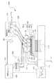
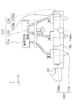
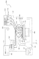
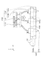
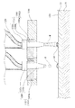
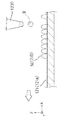
図1から図4は本発明の一の実施形態に係る三次元造形物の製造装置の構成を示す概略構成図である。このうち、図2は図1に示すC部の拡大図、図4は図3に示すC’部の拡大図である。
Embodiments according to the present invention will be described below with reference to the drawings.
1 to 4 are schematic configuration diagrams showing a configuration of a three-dimensional structure manufacturing apparatus according to an embodiment of the present invention. 2 is an enlarged view of a C portion shown in FIG. 1, and FIG. 4 is an enlarged view of a C ′ portion shown in FIG.
ここで、本実施形態の三次元造形物の製造装置は、2種類の材料供給部(ヘッドベース)を備えている。このうち、図1及び図2は、一の材料供給部(構成材料(三次元造形物を構成する粉末状の粒子と溶媒とバインダーとを含む流動性材料)を供給する材料供給部)を表した図である。また、図3及び図4は、別の一の材料供給部(三次元造形物を形成する際に該三次元造形物を支持する支持部を形成する流動性の支持部形成用材料を供給する材料供給部)を表した図である。
なお、本明細書における「三次元造形」とは、いわゆる立体造形物を形成することを示すものであって、例えば、平板状、いわゆる二次元形状の形状であっても厚さを有する形状を形成することも含まれる。また、「支持する」とは、下側から支持する場合の他、横側から支持する場合や、場合によっては上側から支持する場合も含む意味である。
また、本実施形態の三次元造形物の製造装置は、三次元造形物の構成材料を用いて該三次元造形物の構成層を形成する際に該構成層を支持するための支持層を形成可能な構成になっている。このため、積層方向(Z方向)と交差する方向に凸状となった部分(所謂オーバーハング部)を変形させることなく形成可能な構成である。しかしながら、このような構成に限定されず、支持層を形成しない構成(すなわち支持層形成用材料を使用しない構成)であってもよい。
Here, the three-dimensional structure manufacturing apparatus of the present embodiment includes two types of material supply units (head bases). Among these, FIG.1 and FIG.2 represents one material supply part (Material supply part which supplies a constituent material (The flowable material containing the powder-form particle | grains which comprise a three-dimensional structure, a solvent, and a binder)). FIG. 3 and 4 show another material supply part (a fluid support part forming material for forming a support part for supporting the three-dimensional structure when the three-dimensional structure is formed. It is a figure showing a material supply part.
In addition, “three-dimensional modeling” in the present specification indicates that a so-called three-dimensional model is formed, and for example, a plate shape, a so-called two-dimensional shape, has a shape having a thickness. Forming is also included. Further, “support” means not only the case of supporting from the lower side, but also the case of supporting from the lateral side and, in some cases, the case of supporting from the upper side.
In addition, the three-dimensional structure manufacturing apparatus of the present embodiment forms a support layer for supporting the constituent layer when forming the constituent layer of the three-dimensional structure using the constituent material of the three-dimensional structure. It has a possible configuration. For this reason, it is a structure which can be formed, without deform | transforming the part (what is called an overhang part) which became convex shape in the direction which cross | intersects a lamination direction (Z direction). However, it is not limited to such a configuration, and may be a configuration in which a support layer is not formed (that is, a configuration in which a support layer forming material is not used).
図1から図4に示す三次元造形物の製造装置2000(以下、形成装置2000という)は、基台110と、基台110に備える駆動手段としての駆動装置111によって、図示するX、Y、Z方向の移動、あるいはZ軸を中心とする回転方向に駆動可能に備えられたステージ120を備えている。
そして、図1及び図2で表されるように、一方の端部が基台110に固定され、他方の端部に構成材料を吐出する構成材料吐出部1230を備えるヘッドユニット1400を複数保持するヘッドベース1100が保持固定される、ヘッドベース支持部130を備えている。
また、図3及び図4で表されるように、一方の端部が基台110に固定され、他方の端部に三次元造形物を支持する支持層形成用材料を吐出する支持層形成用材料吐出部1730を備えるヘッドユニット1900を複数保持するヘッドベース1600が保持固定される、ヘッドベース支持部730と、を備えている。
ここで、ヘッドベース1100と、ヘッドベース1600とは、XY平面において並列に設けられている。
なお、構成材料吐出部1230と支持層形成用材料吐出部1730とは同様の構成のものである。ただし、このような構成に限定されない。
A three-dimensional structure manufacturing apparatus 2000 (hereinafter, referred to as a forming apparatus 2000) illustrated in FIGS. 1 to 4 includes a
As shown in FIGS. 1 and 2, a plurality of
As shown in FIGS. 3 and 4, one end is fixed to the
Here, the
The constituent
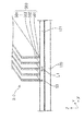
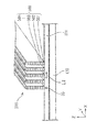
ステージ120上には脱着可能の造形ステージ121が置かれ、造形ステージ121の形成面121a(図5参照)に、三次元造形物の積層体500が形成される過程での層501、502及び503が形成される。造形ステージ121の形成面121aに形成された三次元造形物の積層体500は、形成装置2000での形成後、熱エネルギーなどのエネルギーを付与することにより、脱脂(構成材料に含まれる溶媒やバインダーの少なくとも一部を分解除去すること)や焼結が行われる。そして、この三次元造形物の積層体500の脱脂や焼結は、形成装置2000とは別に設けられる不図示の熱エネルギーを付与可能な恒温槽などに、造形ステージ121ごとセットして行われる。このため、造形ステージ121は高い耐熱性を有することが要求される。そこで、造形ステージ121として、例えばセラミック板を用いることで、高い耐熱性を得ることができ、更に焼結(あるいは溶融されてもよい)される三次元造形物の構成材料との反応性も低く、三次元造形物の積層体500の変質を防止することができる。なお、図1及び図3では、説明の便宜上、層501、502及び503の3層を例示したが、所望の三次元造形物の積層体500の形状まで(図1及び図3中の層50nまで)積層される。
ここで、層501、502、503、・・・50nは、各々、支持層形成用材料吐出部1730から吐出される支持層形成用材料で形成される支持層300と、構成材料吐出部1230から吐出される構成材料で形成される構成層310と、で構成される。
なお、基台110には、造形ステージ121の重量を測定可能な検出部810が設けられており、造形ステージ121に形成される積層体500の各層501、502、503、・・・50nの重量を層毎に測定可能な構成になっている。
A
Here, the
The
また、本実施形態の形成装置2000は、脱脂や焼結とは別に、構成材料に含まれる溶媒の揮発を促進させる乾燥部としての赤外線ヒーター800を備えている。赤外線ヒーター800の制御については、後述する。ただし、乾燥部の構成に特に限定は無い。赤外線ヒーター800のように熱エネルギーを付与する構成のもののほか、ファンなどの送風部であってもよい。
Further, the forming
また、図2は、図1に示すヘッドベース1100を示すC部拡大概念図である。図2に示すように、ヘッドベース1100は、複数のヘッドユニット1400が保持されている。詳細は後述するが、1つのヘッドユニット1400は、構成材料供給装置1200に備える構成材料吐出部1230が保持治具1400aに保持されることで構成される。構成材料吐出部1230は、吐出ノズル1230aと、材料供給コントローラー1500によって吐出ノズル1230aから構成材料を吐出させる吐出駆動部1230bと、を備えている。
FIG. 2 is an enlarged conceptual view of a C portion showing the
また、図4は、図3に示すヘッドベース1600を示すC’部拡大概念図である。ここで、ヘッドベース1600はヘッドベース1100と同様の構成である。具体的には、図4に示すように、ヘッドベース1600は、複数のヘッドユニット1900が保持されている。ヘッドユニット1900は、支持層形成用材料供給装置1700に備える支持層形成用材料吐出部1730が保持治具1900aに保持されることで構成される。支持層形成用材料吐出部1730は、吐出ノズル1730aと、材料供給コントローラー1500によって吐出ノズル1730aから支持層形成用材料を吐出させる吐出駆動部1730bと、を備えている。
FIG. 4 is an enlarged conceptual diagram of a C ′ portion showing the
図1で表されるように、構成材料吐出部1230は、ヘッドベース1100に保持されるヘッドユニット1400それぞれに対応させた構成材料を収容した構成材料供給ユニット1210と供給チューブ1220により接続されている。そして、所定の構成材料が構成材料供給ユニット1210から構成材料吐出部1230に供給される。構成材料供給ユニット1210には、本実施形態に係る形成装置2000によって造形される三次元造形物の積層体500の構成材料が構成材料収容部1210aに収容され、個々の構成材料収容部1210aは、供給チューブ1220によって、個々の構成材料吐出部1230に接続されている。このように、個々の構成材料収容部1210aを備えることにより、ヘッドベース1100から、複数の異なる種類の材料を供給することができる。
As shown in FIG. 1, the constituent
図3で表されるように、支持層形成用材料吐出部1730は、ヘッドベース1600に保持されるヘッドユニット1900それぞれに対応させた支持層形成用材料を収容した支持層形成用材料供給ユニット1710と供給チューブ1720により接続されている。そして、所定の支持層形成用材料が支持層形成用材料供給ユニット1710から支持層形成用材料吐出部1730に供給される。支持層形成用材料供給ユニット1710には、三次元造形物の積層体500を造形する際の支持層を構成する支持層形成用材料が支持層形成用材料収容部1710aに収容され、個々の支持層形成用材料収容部1710aは、供給チューブ1720によって、個々の支持層形成用材料吐出部1730に接続されている。このように、個々の支持層形成用材料収容部1710aを備えることにより、ヘッドベース1600から、複数の異なる種類の支持層形成用材料を供給することができる。
As shown in FIG. 3, the support layer forming
構成材料及び支持層形成用材料としては、例えばマグネシウム(Mg)、鉄(Fe)、コバルト(Co)やクロム(Cr)、アルミニウム(Al)、チタン(Ti)、銅(Cu)、ニッケル(Ni)の単体粉末、もしくはこれらの金属を1つ以上含む合金粉末(マルエージング鋼、ステンレス、コバルトクロムモリブデン、チタニウム合金、ニッケル合金、アルミニウム合金、コバルト合金、コバルトクロム合金)、もしくはこれらから選択される単体粉末、または合金粉末を組み合わせた混合粉末を、溶剤と、バインダーとを含むスラリー状(あるいはペースト状)の混合材料などにして用いることが可能である。
また、ポリアミド、ポリアセタール、ポリカーボネート、変性ポリフェニレンエーテル、ポリブチレンテレフタレート、ポリエチレンテレフタレートなどの汎用エンジニアリングプラスチックを用いることが可能である。その他、ポリサルフォン、ポリエーテルサルフォン、ポリフェニレンサルファイド、ポリアリレート、ポリイミド、ポリアミドイミド、ポリエーテルイミド、ポリエーテルエーテルケトンなどのエンジニアリングプラスチックも用いることが可能である。
このように、構成材料及び支持層形成用材料に特に限定はなく、上記金属以外の金属やセラミックスや樹脂等も使用可能である。また、二酸化ケイ素、二酸化チタン、酸化アルミニウム、酸化ジルコニウムなどを好ましく使用可能である。
For example, magnesium (Mg), iron (Fe), cobalt (Co), chromium (Cr), aluminum (Al), titanium (Ti), copper (Cu), nickel (Ni) ) Simple substance powder or alloy powder containing one or more of these metals (maraging steel, stainless steel, cobalt chrome molybdenum, titanium alloy, nickel alloy, aluminum alloy, cobalt alloy, cobalt chrome alloy), or selected from these It is possible to use a mixed powder obtained by combining a single powder or an alloy powder as a slurry (or paste) mixed material containing a solvent and a binder.
In addition, general-purpose engineering plastics such as polyamide, polyacetal, polycarbonate, modified polyphenylene ether, polybutylene terephthalate, and polyethylene terephthalate can be used. In addition, engineering plastics such as polysulfone, polyethersulfone, polyphenylene sulfide, polyarylate, polyimide, polyamideimide, polyetherimide, and polyetheretherketone can also be used.
Thus, there is no limitation in particular in a constituent material and a support layer formation material, Metals other than the said metal, ceramics, resin, etc. can be used. Further, silicon dioxide, titanium dioxide, aluminum oxide, zirconium oxide and the like can be preferably used.
溶剤としては、例えば、水;エチレングリコールモノメチルエーテル、エチレングリコールモノエチルエーテル、プロピレングリコールモノメチルエーテル、プロピレングリコールモノエチルエーテル等の(ポリ)アルキレングリコールモノアルキルエーテル類;酢酸エチル、酢酸n−プロピル、酢酸iso−プロピル、酢酸n−ブチル、酢酸iso−ブチル等の酢酸エステル類;ベンゼン、トルエン、キシレン等の芳香族炭化水素類;メチルエチルケトン、アセトン、メチルイソブチルケトン、エチル−n−ブチルケトン、ジイソプロピルケトン、アセチルアセトン等のケトン類;エタノール、プロパノール、ブタノール等のアルコール類;テトラアルキルアンモニウムアセテート類;ジメチルスルホキシド、ジエチルスルホキシド等のスルホキシド系溶剤;ピリジン、γ−ピコリン、2,6−ルチジン等のピリジン系溶剤;テトラアルキルアンモニウムアセテート(例えば、テトラブチルアンモニウムアセテート等)等のイオン液体等が挙げられ、これらから選択される1種または2種以上を組み合わせて用いることができる。
バインダーとしては、例えば、アクリル樹脂、エポキシ樹脂、シリコーン樹脂、セルロース系樹脂或いはその他の合成樹脂又はPLA(ポリ乳酸)、PA(ポリアミド)、PPS(ポリフェニレンサルファイド)或いはその他の熱可塑性樹脂である。また、紫外線の照射により重合する紫外線硬化樹脂をバインダーに用いてもよい。
Examples of the solvent include water; (poly) alkylene glycol monoalkyl ethers such as ethylene glycol monomethyl ether, ethylene glycol monoethyl ether, propylene glycol monomethyl ether, propylene glycol monoethyl ether; ethyl acetate, n-propyl acetate, acetic acid acetates such as iso-propyl, n-butyl acetate and iso-butyl acetate; aromatic hydrocarbons such as benzene, toluene and xylene; methyl ethyl ketone, acetone, methyl isobutyl ketone, ethyl n-butyl ketone, diisopropyl ketone, acetylacetone Ketones such as ethanol; alcohols such as ethanol, propanol, butanol; tetraalkylammonium acetates; dimethyl sulfoxide, diethyl sulfoxide, etc. One type selected from these, including phosphine solvents; pyridine solvents such as pyridine, γ-picoline, and 2,6-lutidine; and ionic liquids such as tetraalkylammonium acetate (for example, tetrabutylammonium acetate). Alternatively, two or more kinds can be used in combination.
Examples of the binder include acrylic resin, epoxy resin, silicone resin, cellulosic resin, other synthetic resins, PLA (polylactic acid), PA (polyamide), PPS (polyphenylene sulfide), and other thermoplastic resins. Further, an ultraviolet curable resin that is polymerized by irradiation with ultraviolet rays may be used as the binder.
形成装置2000には、図示しない、例えばパーソナルコンピューター等のデータ出力装置から出力される三次元造形物の造形用データに基づいて、上述したステージ120、構成材料供給装置1200に備える構成材料吐出部1230、並びに、支持層形成用材料供給装置1700に備える支持層形成用材料吐出部1730を制御する制御手段としての制御ユニット400を備えている。そして、制御ユニット400は、ステージ120及び構成材料吐出部1230が連携して駆動及び動作するよう制御し、ステージ120及び支持層形成用材料吐出部1730が連携して駆動及び動作するよう制御する。
The forming
基台110に移動可能に備えられているステージ120は、制御ユニット400からの制御信号に基づき、ステージコントローラー410においてステージ120の移動開始と停止、移動方向、移動量、移動速度などを制御する信号が生成され、基台110に備える駆動装置111に送られ、図示するX、Y、Z方向にステージ120が移動する。ヘッドユニット1400に備える構成材料吐出部1230では、制御ユニット400からの制御信号に基づき、材料供給コントローラー1500において構成材料吐出部1230に備える吐出駆動部1230bにおける吐出ノズル1230aからの材料吐出量などを制御する信号が生成され、生成された信号により吐出ノズル1230aから所定量の構成材料が吐出される。
同様に、ヘッドユニット1900に備える支持層形成用材料吐出部1730では、制御ユニット400からの制御信号に基づき、材料供給コントローラー1500において支持層形成用材料吐出部1730に備える吐出駆動部1730bにおける吐出ノズル1730aからの材料吐出量などを制御する信号が生成され、生成された信号により吐出ノズル1730aから所定量の支持層形成用材料が吐出される。
The
Similarly, in the support layer forming
次に、ヘッドユニット1400についてさらに詳細に説明する。なお、ヘッドユニット1900は、ヘッドユニット1400と同様の構成である。このため、ヘッドユニット1900についての詳細な構成の説明は省略する。
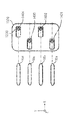
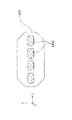
図5及び図6〜図8は、ヘッドベース1100に複数保持されるヘッドユニット1400及び構成材料吐出部1230の保持形態の一例を示し、このうち図5は、図2に示す矢印D方向からのヘッドベース1100の外観図である。
Next, the
5 and 6 to 8 show an example of a holding form of a plurality of
図5に示すように、ヘッドベース1100に複数のヘッドユニット1400が、図示しない固定手段によって保持されている。また、図6〜図8で表されるように、本実施形態に係る形成装置2000のヘッドベース1100では、図下方より第1列目のヘッドユニット1401、第2列目のヘッドユニット1402、第3列目のヘッドユニット1403、そして第4列目のヘッドユニット1404の、4ユニットが千鳥状(互い違い)に配置されたヘッドユニット1400を備えている。そして、図6で表されるように、ステージ120をヘッドベース1100に対してX方向に移動させながら各ヘッドユニット1400から構成材料を吐出させて構成層構成部50(構成層構成部50a、50b、50c及び50d)が形成される。構成層構成部50の形成手順については後述する。
なお、図示しないが、それぞれのヘッドユニット1401〜1404に備える構成材料吐出部1230は、吐出駆動部1230bを介して構成材料供給ユニット1210に供給チューブ1220で繋がれる構成となっている。
As shown in FIG. 5, a plurality of
Although not shown, the constituent
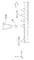
図5に示すように、構成材料吐出部1230は吐出ノズル1230aから、ステージ120上に載置された造形ステージ121の形成面121aに向けて三次元造形物の構成材料である流動性材料Mが吐出される。ヘッドユニット1401では、流動性材料Mが液滴状で吐出される吐出形態を例示し、ヘッドユニット1402では、流動性材料Mが連続体状で供給される吐出形態を例示している。流動性材料Mの吐出形態は、液滴状であっても連続体状であっても、どちらでもよいが、本実施形態では流動性材料Mは液滴状で吐出される形態により説明する。
なお、構成材料吐出部1230及び支持層形成用材料吐出部1730はこのような構成に限定されず、エクストルーダーなど更に異なる方式の材料供給部であってもよい。
As shown in FIG. 5, the constituent
The constituent
吐出ノズル1230aから液滴状に吐出された流動性材料Mは、略重力方向に飛翔し、造形ステージ121上に着弾する。ステージ120は移動し、着弾した流動性材料Mにより構成層構成部50が形成される。この構成層構成部50の集合体が、造形ステージ121の形成面121a上に形成される三次元造形物の積層体500の構成層310(図1参照)として形成される。
The fluid material M discharged in the form of droplets from the
次に、構成層構成部50の形成手順について、図6〜図8、図9及び図10を用いて説明する。
図6〜図8は、本実施形態のヘッドユニット1400の配置と、構成層構成部50の形成形態と、の関係を概念的に説明する平面図である。そして、図9及び図10は、構成層構成部50の形成形態を概念的に表す側面図である。
Next, a procedure for forming the constituent layer
6 to 8 are plan views conceptually illustrating the relationship between the arrangement of the
まず、ステージ120が+X方向に移動すると、複数の吐出ノズル1230aから流動性材料Mが液滴状に吐出され、造形ステージ121の形成面121aの所定の位置に流動性材料Mが配置され、構成層構成部50が形成される。
より具体的には、まず、図9で表されるように、ステージ120を+X方向に移動させながら、複数の吐出ノズル1230aから造形ステージ121の形成面121aの所定の位置に一定の間隔で流動性材料Mを配置させる。
First, when the
More specifically, as shown in FIG. 9, first, while moving the
次に、図10で表されるように、ステージ120を図1に示す−X方向に移動させながら、一定の間隔で配置された流動性材料Mの間を埋めるように新たに流動性材料Mを配置させる。
ただし、ステージ120を+X方向に移動させながら、複数の吐出ノズル1230aから造形ステージ121の所定の位置に流動性材料Mが重なるように(間隔を空けないように)配置させる構成(ステージ120のX方向における往復移動で構成層構成部50を形成する構成ではなく、ステージ120のX方向における片側の移動のみで構成層構成部50を形成する構成)としても良い。
Next, as shown in FIG. 10, while moving the
However, while moving the
上記のように構成層構成部50を形成することによって、図6で表されるような、各ヘッドユニット1401、1402、1403及び1404のX方向における1ライン分(Y方向における1ライン目)の構成層構成部50(構成層構成部50a、50b、50c及び50d)が形成される。
By forming the constituent
次に、各ヘッドユニット1401、1402、1403及び1404のY方向における2ライン目の構成層構成部50’(構成層構成部50a’、50b’、50c’及び50d’)を形成するため、−Y方向にヘッドベース1100を移動させる。移動量は、ノズル間のピッチをPとすると、P/n(nは自然数)ピッチ分だけ−Y方向に移動させる。本実施例ではnを3として説明する。
図9及び図10で表されるような、上記と同様な動作を行うことで、図7で表されるような、Y方向における2ライン目の構成層構成部50’(構成層構成部50a’、50b’、50c’及び50d’)が形成される。
Next, in order to form the second layer constituent layer
By performing the same operation as described above as represented in FIG. 9 and FIG. 10, the constituent
次に、各ヘッドユニット1401、1402、1403及び1404のY方向における3ライン目の構成層構成部50’’(構成層構成部50a’’、50b’’、50c’’及び50d’’)を形成するため、−Y方向にヘッドベース1100を移動させる。移動量は、P/3ピッチ分だけ−Y方向に移動させる。
そして、図9及び図10で表されるような、上記と同様な動作を行うことで、図8で表されるような、Y方向における3ライン目の構成層構成部50’’
(構成層構成部50a’’、50b’’、50c’’及び50d’’)が形成され、積層方向における1層分の構成層310を得ることができる。
Next, the third layer constituent layer
Then, by performing the same operation as described above as shown in FIG. 9 and FIG. 10, the constituent layer constituting unit 50 '' of the third line in the Y direction as shown in FIG.
(Constituent layer
また、構成材料吐出部1230から吐出される流動性材料Mを、ヘッドユニット1401、1402、1403、1404のいずれか1ユニット、あるいは2ユニット以上からその他ヘッドユニットと異なる構成材料を吐出供給することもできる。従って、本実施形態に係る形成装置2000を用いることによって、異種材料から形成される三次元造形物を得ることができる。
Further, the flowable material M discharged from the constituent
なお、第1層目の層501において、上述したように構成層310を形成する前或いは後に、支持層形成用材料吐出部1730から支持層形成用材料を吐出させて、同様の方法で、支持層300を形成することができる。そして、層501に積層させて層502、503、・・・50nを形成する際にも、同様に、構成層310及び支持層300を形成することができる。
In the
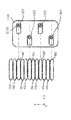
上述の本実施形態に係る形成装置2000が備えるヘッドユニット1400及び1900の数及び配列は、上述した数及び配列に限定されない。図11及び図12に、その例として、ヘッドベース1100に配置されるヘッドユニット1400の、その他の配置の例を模式図的に示す。
The number and arrangement of the
図11は、ヘッドベース1100にヘッドユニット1400をX軸方向に複数、並列させた形態を示す。図12は、ヘッドベース1100にヘッドユニット1400を格子状に配列させた形態を示す。なお、いずれも配列されるヘッドユニットの数は、図示の例に限定されない。
FIG. 11 shows a form in which a plurality of
次に、上述の本実施形態に係る形成装置2000を用いて実行する構成層構成部50の形成手順の例について詳細に説明する。
図13は、本実施形態に係る三次元造形物の製造装置(形成装置2000)を用いて、幅L1の複数の三次元造形物の積層体500を製造する際の製造例を表す概略図である。
一方、図15は、従来の三次元造形物の製造装置を用いて製造する三次元造形物の製造例を表す概略図であり、図13で表される幅L1の複数の三次元造形物の積層体500と同様の三次元造形物の積層体500を製造しようとした状態を表している。
なお、図13及び図15は、支持層形成用材料吐出部1730から支持層形成用材料を吐出させることなく構成材料吐出部1230から構成材料のみを吐出させて三次元造形物の積層体500を製造する際の製造例である。
Next, an example of a procedure for forming the constituent
FIG. 13 is a schematic diagram illustrating a manufacturing example when manufacturing a
On the other hand, FIG. 15 is a schematic diagram illustrating an example of manufacturing a three-dimensional structure manufactured using a conventional three-dimensional structure manufacturing apparatus, and a plurality of three-dimensional structures having a width L1 illustrated in FIG. The state which is going to manufacture the
13 and 15 show the three-
本実施形態に係る形成装置2000は、図1〜図4で表されるような構造をしている。
詳細には、本実施形態の形成装置2000は、三次元造形物の構成材料となる粒子と溶剤とを含む流動性材料Mを噴射する噴射部としての構成材料吐出部1230と、構成材料吐出部1230から噴射されて形成される流動性材料Mの層(層501、502、503、・・・50n)が積層されるステージ120(造形ステージ121)と、ステージ120における流動性材料Mの重量を検出する検出部810と、ステージ120における流動性材料Mに含まれる溶剤を揮発させる赤外線ヒーター800と、を備えている。
ここで、制御ユニット400は、判断部として、検出部810の検出結果に基づいて溶剤が所定以上に揮発したか否かを判断することができる。そして、詳細は図14を用いて後述するが、制御ユニット400が、流動性材料Mの層の積層方向(Z方向)における所定の層毎(例えば1層毎)に溶剤が所定以上に揮発したか否かを判断し、溶剤が所定以上に揮発したと判断したことに伴って、流動性材料Mの次の層を積層する(積層方向における次の層を形成する)ことができる。なお、「所定の層毎」とは、1層毎だけでなく複数層毎も含む意味である。
このため、本実施形態の形成装置2000は、図13において所望の幅である幅L1の複数の三次元造形物の積層体500が形成されていることで示されるように、流動性材料Mの層を積層する際に、下側の層が乾燥していることで下側の層が横に広がることを抑制することができる。したがって、本実施形態の形成装置2000は、三次元造形物を構成する流動性材料Mを積層することに伴い、該流動性材料Mの積層体500が変形することを抑制することができる構成になっている。
The forming
Specifically, the forming
Here, the
For this reason, the forming
一方、従来の三次元造形物の製造装置は、溶剤が所定以上に揮発したか否かを判断することなく流動性材料Mの層を積層する。このため、所望の幅である幅L1の複数の三次元造形物の積層体500を形成しようとしても、図15で表されるように、最上部の層以外の層においては、流動性材料Mの層を積層する際に上側に形成される層の重さにより下側の層が横に広がり、所望の幅である幅L1より広い幅L2となる。したがって、三次元造形物を構成する流動性材料Mを積層することに伴い、該流動性材料Mの積層体500が変形してしまう。
On the other hand, the conventional three-dimensional structure manufacturing apparatus stacks the layer of the flowable material M without determining whether or not the solvent has volatilized more than a predetermined amount. For this reason, even if it is going to form the
また、本実施形態の形成装置2000は、図1及び図3で表されるように、制御ユニット400にROM、HDD及びEEPROMなどの少なくとも1つからなる情報の格納部820を備えている。そして、格納部820は、該情報のうちの1つとして、流動性材料Mに含まれる溶剤の揮発率と流動性材料Mの粘度との対応パラメーターを格納している。そして、制御ユニット400は、該対応パラメーターを用いて演算される流動性材料Mの所定の粘度に対応する揮発率に基づいて、溶剤が所定以上に揮発したか否かを判断できる。
ここで、三次元造形物を製造する際に求められる精度(流動性材料Mの重さで下側の層が横に広がり流動性材料Mの積層体500が変形することなど)は、流動性材料Mの粘度との相関性が高い。このため、本実施形態の形成装置2000は、特に効果的に、三次元造形物を構成する流動性材料Mを積層することに伴い、該流動性材料Mの積層体500が変形することを抑制することができる構成になっている。
ただし、このような構成に限定されず、溶剤の揮発率と流動性材料の粘度との対応パラメーターを使用する代わりに、溶剤の揮発率と単位体積あたりの粒子密度や、溶剤の揮発率と積層の体積、溶剤の揮発率と画像の色調との相関関係などを使用してもよい。
In addition, as illustrated in FIGS. 1 and 3, the forming
Here, the accuracy required when manufacturing the three-dimensional structure (such as the fact that the lower layer spreads horizontally due to the weight of the fluid material M and the
However, the present invention is not limited to such a configuration. Instead of using the corresponding parameter of the volatility of the solvent and the viscosity of the flowable material, the volatility of the solvent and the particle density per unit volume, the volatility of the solvent and the lamination The volume, the volatilization rate of the solvent, and the correlation between the color tone of the image and the like may be used.
また、上記のように、本実施形態の形成装置2000は、乾燥部として赤外線ヒーター800を備えている。そして、このように乾燥部を加熱部とすることや乾燥部を送風部とすることで、言い換えると、乾燥部が加熱部及び送風部の少なくとも1つを有することで、乾燥部を簡単に構成することができる。
Further, as described above, the forming
ここで、本実施形態における赤外線ヒーター800は、制御ユニット400の制御により、流動性材料Mに含まれる溶剤の揮発率に応じて出力変更可能である。このため、揮発し易い又は揮発し難い溶剤を使用する場合や製造する三次元造形物の大きさなどに基づき、溶剤の揮発率が高い(揮発速度が速い)場合及び低い(揮発速度が遅い)場合に応じて乾燥度合を調整することができる。
ここで、乾燥度合の調整は、赤外線ヒーター800の出力値(パワー)を調整することのほか、乾燥時間(出力時間)を調整すること、赤外線ヒーター800と流動性材料Mの積層体500との距離を調整すること、複数の乾燥部(赤外線ヒーター800)のうちから出力する乾燥部の数を調整すること、などにより実行可能である。
Here, the output of the
Here, the degree of drying is adjusted by adjusting the output value (power) of the
次に、上記形成装置2000を用いて行う三次元造形物の製造方法の一例についてフローチャートを用いて説明する。
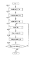
ここで、図14は、本実施例に係る三次元造形物の製造方法のフローチャートであり、複数の層を積層方向(Z方向)に積層して三次元造形物の積層体500を形成するうちの所定層分(例えば1層分)に対応するフローチャートである。このため、三次元造形物の積層体500を完成させるために、必要に応じて、図14で表されるフローを繰り返す。
Next, an example of a manufacturing method of a three-dimensional structure performed using the forming
Here, FIG. 14 is a flowchart of the manufacturing method of the three-dimensional structure according to the present embodiment, in which a plurality of layers are stacked in the stacking direction (Z direction) to form the
図14で表されるように、本実施例の三次元造形物の製造方法においては、三次元造形物のデータを取得し本実施例の三次元造形物の製造方法を開始すると、最初にステップS110の検出工程で、検出部810によりステージ120の重量を検出する。本ステップは、ステージ120(造形ステージ121)上に流動性材料Mの層が形成されていない状態の重量検出に相当する。
As shown in FIG. 14, in the method for manufacturing a three-dimensional structure according to the present embodiment, when the data for the three-dimensional structure is acquired and the method for manufacturing the three-dimensional structure according to the present embodiment is started, the first step is performed. In the detection step of S110, the
次に、ステップS120の噴射工程で、ステージ120を移動させながら構成材料吐出部1230から(場合によっては支持層形成用材料吐出部1730からも)流動性材料Mを吐出させ、所定層分(例えば層501の1層分)に対応して該所定層分の三次元造形物の積層体500を形成する。
Next, in the injection step of step S120, the fluid material M is discharged from the constituent material discharge unit 1230 (in some cases also from the support layer forming material discharge unit 1730) while moving the
次に、ステップS130の検出工程で、検出部810によりステージ120の重量を検出する。本ステップは、ステージ120(造形ステージ121)上に所定層分の流動性材料Mの層が形成された直後の状態の重量検出に相当する。
なお、本ステップの重量の検出結果とステップS110の重量の検出結果とを比較することで、構成材料吐出部1230から所定の吐出量で流動性材料Mが吐出されたか否かを判断可能である。構成材料吐出部1230から所定の吐出量で流動性材料Mが吐出されていないと判断できる場合には、本実施例の三次元造形物の製造方法を終了させてもよい。
Next, the weight of the
In addition, it is possible to determine whether or not the flowable material M is discharged from the constituent
次に、ステップS140の乾燥工程で、赤外線ヒーター800によりステージ120上に形成された所定層分の流動性材料Mを所定の乾燥条件で乾燥させる。なお、該乾燥工程は、流動性材料Mに含まれる溶剤の揮発率(揮発速度)に応じて制御ユニット400の制御により自動で出力変更させながら変えてもよいし、ユーザーが指定した出力条件で実行してもよい。
Next, in the drying process of step S140, the flowable material M for a predetermined layer formed on the
次に、ステップS150の検出工程で、検出部810によりステージ120の重量を検出する。本ステップは、ステージ120(造形ステージ121)上に形成された所定層分の流動性材料Mの乾燥率を演算するための重量検出に相当する。
Next, the weight of the
次に、ステップS160の演算工程で、ステップS130の重量の検出結果からステップS150の重量の検出結果を減じることで、流動性材料Mの乾燥率を演算する。 Next, in the calculation step of step S160, the drying rate of the flowable material M is calculated by subtracting the weight detection result of step S150 from the weight detection result of step S130.
そして、ステップS170の判断工程で、流動性材料Mに含まれる溶剤が所定以上に揮発したか否かを判断する。
ここで、所定以上に揮発したと判断した場合は、本実施例の三次元造形物の製造方法のフローを終了する(必要に応じて、所定層分の次の層に対応して図14のフローを繰り返す)。
一方、所定以上に揮発していないと判断した場合は、ステップS140の乾燥工程に戻り、さらに流動性材料Mに含まれる溶剤を揮発させる。
なお、所定以上に揮発したか否かの判断基準は、例えば、流動性材料Mに含まれる溶剤の揮発率と流動性材料Mの粘度との対応パラメーター(所定の粘度に対応する所定の揮発率になったか否か)に基づいて設定できる。
In step S170, it is determined whether or not the solvent contained in the fluid material M has volatilized more than a predetermined amount.
Here, if it is determined that the volatilization has exceeded a predetermined level, the flow of the manufacturing method of the three-dimensional structure according to the present embodiment is terminated (if necessary, corresponding to the next layer corresponding to the predetermined layer in FIG. Repeat the flow).
On the other hand, if it is determined that it has not volatilized more than a predetermined amount, the process returns to the drying step of step S140, and the solvent contained in the fluid material M is further volatilized.
Note that the criterion for determining whether or not volatilization exceeds a predetermined value is, for example, a parameter corresponding to the volatilization rate of the solvent contained in the fluid material M and the viscosity of the fluid material M (a predetermined volatilization rate corresponding to the predetermined viscosity). Can be set based on whether or not.
上記のように、本実施例の三次元造形物の製造方法は、層を積層することにより三次元造形物を製造する三次元造形物の製造方法である。
そして、本実施例の三次元造形物の製造方法は、三次元造形物の構成材料となる粒子と溶剤とを含む流動性材料Mの層をステージ120に噴射する噴射工程(ステップS120)を、流動性材料Mの層の積層方向における所定の層分(例えば1層分)実行し、ステージ120における流動性材料Mの重量を検出する検出工程(ステップS130及びS150)と、ステージ120における流動性材料Mに含まれる溶剤を揮発させる乾燥工程(ステップS140)と、検出工程の検出結果に基づいて溶剤が所定以上に揮発したか否かを判断する判断工程(ステップS160及びS170)と、を実行することで、所定の層毎に、溶剤が所定以上に揮発したと判断されることに伴って、流動性材料Mの次の層を積層する(必要に応じて図14のフローを繰り返す)。
このため、本実施例の三次元造形物の製造方法は、流動性材料Mの層を積層する際に、下側の層が乾燥していることで下側の層が横に広がることを抑制することができる。したがって、本実施例の三次元造形物の製造方法は、三次元造形物を構成する流動性材料Mを積層することに伴い、該流動性材料の積層体が変形することを抑制することができる。
As described above, the method for manufacturing a three-dimensional structure according to the present embodiment is a method for manufacturing a three-dimensional structure that manufactures a three-dimensional structure by stacking layers.
And the manufacturing method of the three-dimensional structure according to the present embodiment includes an injection step (step S120) for injecting a layer of the fluid material M containing particles and a solvent, which are constituent materials of the three-dimensional structure, onto the
For this reason, the manufacturing method of the three-dimensional structure according to the present embodiment suppresses the lower layer from spreading laterally when the layer of the fluid material M is laminated, because the lower layer is dry. can do. Therefore, the manufacturing method of the three-dimensional structure according to the present embodiment can suppress the deformation of the flowable material stack as the flowable material M constituting the three-dimensional structure is stacked. .
本発明は、上述の実施例に限られるものではなく、その趣旨を逸脱しない範囲において種々の構成で実現することができる。例えば、発明の概要の欄に記載した各形態中の技術的特徴に対応する実施例中の技術的特徴は、上述の課題の一部又は全部を解決するために、あるいは、上述の効果の一部又は全部を達成するために、適宜、差し替えや、組み合わせを行うことが可能である。また、その技術的特徴が本明細書中に必須なものとして説明されていなければ、適宜、削除することが可能である。 The present invention is not limited to the above-described embodiments, and can be realized with various configurations without departing from the spirit of the present invention. For example, the technical features in the embodiments corresponding to the technical features in the embodiments described in the summary section of the invention are intended to solve part or all of the above-described problems, or one of the above-described effects. In order to achieve part or all, replacement or combination can be appropriately performed. Further, if the technical feature is not described as essential in the present specification, it can be deleted as appropriate.
50、50a、50b、50c、50d…構成層構成部、110…基台、
111…駆動装置、120…ステージ、121…造形ステージ、121a…形成面、
130…ヘッドベース支持部、300…支持層、310…構成層、
400…制御ユニット(判断部)、410…ステージコントローラー、
500…三次元造形物の積層体、501、502及び503…層、600…有機膜、
650…恒温槽、730…ヘッドベース支持部、800…赤外線ヒーター(乾燥部)、
810…検出部、820…格納部、1100…ヘッドベース、
1200…構成材料供給装置、1210…構成材料供給ユニット、
1210a…構成材料収容部、1220…供給チューブ、
1230…構成材料吐出部(噴射部)、1230a…吐出ノズル、
1230b…吐出駆動部、1400…ヘッドユニット、1400a…保持治具、
1401、1402、1403、1404…ヘッドユニット、
1500…材料供給コントローラー、1600…ヘッドベース、
1700…支持層形成用材料供給装置、1710…支持層形成用材料供給ユニット、
1710a…支持層形成用材料収容部、1720…供給チューブ、
1730…支持層形成用材料吐出部、1730a…吐出ノズル、
1730b…吐出駆動部、1900…ヘッドユニット、1900a…保持治具、
2000…形成装置(三次元造形物の製造装置)、M…流動性材料(構成材料)
50, 50 a, 50 b, 50 c, 50 d ... constituent layer constituent part, 110 ... base,
111 ... Drive device, 120 ... Stage, 121 ... Modeling stage, 121a ... Forming surface,
130 ... head base support, 300 ... support layer, 310 ... component layer,
400 ... control unit (determination unit), 410 ... stage controller,
500 ... Laminated body of three-dimensional structure, 501, 502 and 503 ... layer, 600 ... organic film,
650 ... constant temperature bath, 730 ... head base support part, 800 ... infrared heater (drying part),
810 ... detection unit, 820 ... storage unit, 1100 ... head base,
1200 ... constituent material supply device, 1210 ... constituent material supply unit,
1210a ... Constituent material storage unit, 1220 ... Supply tube,
1230 ... Constituent material discharge part (injection part), 1230a ... discharge nozzle,
1230b ... discharge driving unit, 1400 ... head unit, 1400a ... holding jig,
1401, 1402, 1403, 1404 ... head unit,
1500 ... Material supply controller, 1600 ... Head base,
1700: Support layer forming material supply device, 1710: Support layer forming material supply unit,
1710a: Support layer forming material container, 1720: Supply tube,
1730: Material discharge part for forming a support layer, 1730a: Discharge nozzle,
1730b ... Discharge drive unit, 1900 ... head unit, 1900a ... holding jig,
2000 ... Forming device (manufacturing device for three-dimensional structure), M ... Flowable material (constituent material)
Claims (5)
前記噴射部から噴射されて形成される前記流動性材料の層が積層されるステージと、
前記ステージにおける前記流動性材料の重量を検出する検出部と、
前記ステージにおける前記流動性材料に含まれる前記溶剤を揮発させる乾燥部と、
前記検出部の検出結果に基づいて前記溶剤が所定以上に揮発したか否かを判断する判断部と、を備え、
前記流動性材料の層の積層方向における所定の層毎に、前記溶剤が所定以上に揮発したと前記判断部が判断したことに伴って、前記流動性材料の次の層を積層することを特徴とする三次元造形物の製造装置。 An injection unit that injects a fluid material containing particles and a solvent that are constituent materials of the three-dimensional structure; and
A stage on which a layer of the fluid material formed by being injected from the injection unit is laminated;
A detection unit for detecting the weight of the fluid material in the stage;
A drying unit that volatilizes the solvent contained in the flowable material in the stage;
A determination unit that determines whether or not the solvent has volatilized more than a predetermined amount based on a detection result of the detection unit,
For each predetermined layer in the stacking direction of the layer of the fluid material, the next layer of the fluid material is stacked when the determination unit determines that the solvent has volatilized more than a predetermined amount. A three-dimensional structure manufacturing apparatus.
前記溶剤の揮発率と前記流動性材料の粘度との対応パラメーターを格納する格納部を備え、
前記判断部は、前記対応パラメーターを用いて演算される前記流動性材料の所定の粘度に対応する揮発率に基づいて、前記溶剤が所定以上に揮発したか否かを判断することを特徴とする三次元造形物の製造装置。 In the manufacturing apparatus of the three-dimensional structure described in claim 1,
A storage unit for storing corresponding parameters of the volatilization rate of the solvent and the viscosity of the flowable material;
The determination unit determines whether the solvent has volatilized more than a predetermined value based on a volatilization rate corresponding to a predetermined viscosity of the flowable material calculated using the corresponding parameter. Manufacturing equipment for 3D objects.
前記乾燥部は、加熱部及び送風部の少なくとも1つを有することを特徴とする三次元造形物の製造装置。 In the manufacturing apparatus of the three-dimensional structure according to claim 1 or 2,
The said drying part has at least 1 of a heating part and a ventilation part, The manufacturing apparatus of the three-dimensional structure characterized by the above-mentioned.
前記乾燥部は、前記溶剤の揮発率に応じて出力変更可能であることを特徴とする三次元造形物の製造装置。 In the manufacturing apparatus of the three-dimensional structure according to any one of claims 1 to 3,
The drying unit is capable of changing the output according to the volatilization rate of the solvent.
三次元造形物の構成材料となる粒子と溶剤とを含む流動性材料の層をステージに噴射する噴射工程を、前記流動性材料の層の積層方向における所定の層分実行し、
前記ステージにおける前記流動性材料の重量を検出する検出工程と、前記ステージにおける前記流動性材料に含まれる前記溶剤を揮発させる乾燥工程と、前記検出工程の検出結果に基づいて前記溶剤が所定以上に揮発したか否かを判断する判断工程と、を実行することで、
前記所定の層毎に、前記溶剤が所定以上に揮発したと判断されることに伴って、前記流動性材料の次の層を積層することを特徴とする三次元造形物の製造方法。 It is a manufacturing method of a three-dimensional structure that manufactures a three-dimensional structure by laminating layers,
Performing a spraying step of spraying a layer of fluid material containing particles and a solvent, which are constituent materials of the three-dimensional structure, onto the stage, for a predetermined layer in the stacking direction of the fluid material layer
A detection step for detecting the weight of the flowable material in the stage; a drying step for volatilizing the solvent contained in the flowable material in the stage; and the solvent exceeds a predetermined level based on a detection result of the detection step. By executing a determination step of determining whether or not it has volatilized,
A method for producing a three-dimensional structure, comprising: laminating a next layer of the fluid material for each of the predetermined layers as it is determined that the solvent has volatilized more than a predetermined amount.
Priority Applications (1)
| Application Number | Priority Date | Filing Date | Title |
|---|---|---|---|
| JP2016191543A JP2018051964A (en) | 2016-09-29 | 2016-09-29 | Three-dimensional structure manufacturing apparatus and three-dimensional structure manufacturing method |
Applications Claiming Priority (1)
| Application Number | Priority Date | Filing Date | Title |
|---|---|---|---|
| JP2016191543A JP2018051964A (en) | 2016-09-29 | 2016-09-29 | Three-dimensional structure manufacturing apparatus and three-dimensional structure manufacturing method |
Publications (1)
| Publication Number | Publication Date |
|---|---|
| JP2018051964A true JP2018051964A (en) | 2018-04-05 |
Family
ID=61834936
Family Applications (1)
| Application Number | Title | Priority Date | Filing Date |
|---|---|---|---|
| JP2016191543A Pending JP2018051964A (en) | 2016-09-29 | 2016-09-29 | Three-dimensional structure manufacturing apparatus and three-dimensional structure manufacturing method |
Country Status (1)
| Country | Link |
|---|---|
| JP (1) | JP2018051964A (en) |
Cited By (2)
| Publication number | Priority date | Publication date | Assignee | Title |
|---|---|---|---|---|
| JP2018051969A (en) * | 2016-09-29 | 2018-04-05 | セイコーエプソン株式会社 | Three-dimensional structure manufacturing apparatus and three-dimensional structure manufacturing method |
| US11697159B2 (en) | 2019-11-27 | 2023-07-11 | Seiko Epson Corporation | Three-dimensional shaping device and method for manufacturing three-dimensional shaped object |
-
2016
- 2016-09-29 JP JP2016191543A patent/JP2018051964A/en active Pending
Cited By (2)
| Publication number | Priority date | Publication date | Assignee | Title |
|---|---|---|---|---|
| JP2018051969A (en) * | 2016-09-29 | 2018-04-05 | セイコーエプソン株式会社 | Three-dimensional structure manufacturing apparatus and three-dimensional structure manufacturing method |
| US11697159B2 (en) | 2019-11-27 | 2023-07-11 | Seiko Epson Corporation | Three-dimensional shaping device and method for manufacturing three-dimensional shaped object |
Similar Documents
| Publication | Publication Date | Title |
|---|---|---|
| JP6774020B2 (en) | 3D model manufacturing equipment and 3D model manufacturing method | |
| CN108527854A (en) | The manufacturing method of paste and three-D moulding object | |
| JP6669985B2 (en) | Manufacturing method of three-dimensional objects | |
| JP6981558B2 (en) | 3D modeling stage, 3D modeling equipment and 3D modeling method | |
| CN107020739B (en) | Method for manufacturing three-dimensional shaped object | |
| JP6826321B2 (en) | Modeling stage of 3D model, 3D model manufacturing device and 3D model manufacturing method | |
| CN107160672A (en) | Manufacture method, manufacture device and the three-D moulding object of three-D moulding object | |
| JP6751252B2 (en) | Three-dimensional model manufacturing method and three-dimensional model manufacturing apparatus | |
| JP6751251B2 (en) | Three-dimensional model manufacturing method and three-dimensional model manufacturing apparatus | |
| JP6802517B2 (en) | Modeling stage of 3D model, 3D model manufacturing device and 3D model manufacturing method | |
| CN107825698B (en) | Three-dimensional modeling device, three-dimensional modeling method and storage medium | |
| JP2018051964A (en) | Three-dimensional structure manufacturing apparatus and three-dimensional structure manufacturing method | |
| JP2018138358A (en) | Three-dimensional structure manufacturing apparatus and three-dimensional structure manufacturing method | |
| JP6924380B2 (en) | 3D model manufacturing equipment and 3D model manufacturing method | |
| JP6862735B2 (en) | 3D modeling equipment, manufacturing methods and computer programs | |
| JP2023034377A (en) | Method for manufacturing three-dimensional molding, and three-dimensional molding device | |
| JP2021008095A (en) | Manufacturing apparatus for three-dimensional molded article | |
| US11999108B2 (en) | Three-dimensional shaping device | |
| JP7447465B2 (en) | 3D modeling method | |
| JP2017087612A (en) | Three-dimensional structure manufacturing apparatus and three-dimensional structure manufacturing method | |
| JP6950780B2 (en) | Manufacturing method of 3D model | |
| JP2020192758A (en) | Material set and method for manufacturing three-dimensional object | |
| JP2023034375A (en) | Method for manufacturing three-dimensional molded object and three-dimensional molding apparatus | |
| JP2022026567A (en) | Three-dimensional molding apparatus |