JP2018043403A - Image processing apparatus, image formation apparatus and program - Google Patents
Image processing apparatus, image formation apparatus and program Download PDFInfo
- Publication number
- JP2018043403A JP2018043403A JP2016179180A JP2016179180A JP2018043403A JP 2018043403 A JP2018043403 A JP 2018043403A JP 2016179180 A JP2016179180 A JP 2016179180A JP 2016179180 A JP2016179180 A JP 2016179180A JP 2018043403 A JP2018043403 A JP 2018043403A
- Authority
- JP
- Japan
- Prior art keywords
- pixel
- gradation value
- correction
- value
- unit
- Prior art date
- Legal status (The legal status is an assumption and is not a legal conclusion. Google has not performed a legal analysis and makes no representation as to the accuracy of the status listed.)
- Granted
Links
Images


Classifications
-
- G—PHYSICS
- G06—COMPUTING; CALCULATING OR COUNTING
- G06K—GRAPHICAL DATA READING; PRESENTATION OF DATA; RECORD CARRIERS; HANDLING RECORD CARRIERS
- G06K15/00—Arrangements for producing a permanent visual presentation of the output data, e.g. computer output printers
- G06K15/02—Arrangements for producing a permanent visual presentation of the output data, e.g. computer output printers using printers
- G06K15/12—Arrangements for producing a permanent visual presentation of the output data, e.g. computer output printers using printers by photographic printing, e.g. by laser printers
- G06K15/1238—Arrangements for producing a permanent visual presentation of the output data, e.g. computer output printers using printers by photographic printing, e.g. by laser printers simultaneously exposing more than one point
- G06K15/1257—Arrangements for producing a permanent visual presentation of the output data, e.g. computer output printers using printers by photographic printing, e.g. by laser printers simultaneously exposing more than one point on more than one main scanning line
- G06K15/1261—Arrangements for producing a permanent visual presentation of the output data, e.g. computer output printers using printers by photographic printing, e.g. by laser printers simultaneously exposing more than one point on more than one main scanning line using an array of light sources
-
- G—PHYSICS
- G03—PHOTOGRAPHY; CINEMATOGRAPHY; ANALOGOUS TECHNIQUES USING WAVES OTHER THAN OPTICAL WAVES; ELECTROGRAPHY; HOLOGRAPHY
- G03G—ELECTROGRAPHY; ELECTROPHOTOGRAPHY; MAGNETOGRAPHY
- G03G15/00—Apparatus for electrographic processes using a charge pattern
- G03G15/04—Apparatus for electrographic processes using a charge pattern for exposing, i.e. imagewise exposure by optically projecting the original image on a photoconductive recording material
- G03G15/043—Apparatus for electrographic processes using a charge pattern for exposing, i.e. imagewise exposure by optically projecting the original image on a photoconductive recording material with means for controlling illumination or exposure
-
- H—ELECTRICITY
- H04—ELECTRIC COMMUNICATION TECHNIQUE
- H04N—PICTORIAL COMMUNICATION, e.g. TELEVISION
- H04N1/00—Scanning, transmission or reproduction of documents or the like, e.g. facsimile transmission; Details thereof
- H04N1/46—Colour picture communication systems
- H04N1/56—Processing of colour picture signals
- H04N1/58—Edge or detail enhancement; Noise or error suppression, e.g. colour misregistration correction
Abstract
Description
本発明は、画像処理装置、画像形成装置及びプログラムに関する。 The present invention relates to an image processing apparatus, an image forming apparatus, and a program.
電子写真方式の画像形成装置は、画像データの各画素の階調値に応じて変調されたレーザービームにより、感光体上を走査して露光し、当該露光により形成された静電潜像を現像することによって、画像を形成している。
画像形成の高速化を図るため、複数のレーザービームを並行して走査し、1走査で複数ライン分の画像を形成する画像形成装置も知られている。このように並行して走査される複数のレーザービームは、マルチビームと呼ばれている。
An electrophotographic image forming apparatus scans and exposes a photosensitive member with a laser beam modulated according to the gradation value of each pixel of image data, and develops an electrostatic latent image formed by the exposure. By doing so, an image is formed.
In order to increase the speed of image formation, an image forming apparatus that scans a plurality of laser beams in parallel and forms images for a plurality of lines in one scan is also known. A plurality of laser beams scanned in parallel as described above are called multi-beams.
マルチビームにより画像を形成する場合、各レーザービームの間隔を一定に維持することが好ましいが、実際には、製造時の調整誤差や、経時、環境変化等により各レーザービームのビーム位置がずれ、画質に影響することがある。
例えば、線画像を形成する際、ビーム位置がずれると、線幅が変動することがある。線画像の濃度は線幅に比例するため、線幅の相違によって濃度差が生じる。
When forming an image with multi-beams, it is preferable to keep the interval between the laser beams constant, but in reality, the beam position of each laser beam is shifted due to adjustment errors during manufacturing, aging, environmental changes, etc. May affect image quality.
For example, when forming a line image, the line width may fluctuate if the beam position shifts. Since the density of the line image is proportional to the line width, a difference in density occurs due to the difference in the line width.
ビーム位置のずれによる線幅の変化はわずかであるものの、ラダー画像等はこのような変化が周期的に発生する可能性があり、線幅が変動した部分とそうでない部分の濃度差が規則的に現れてモアレとして観察されてしまう。 Although the change in line width due to beam position shift is slight, such changes may occur periodically in ladder images, etc., and the density difference between the part where the line width fluctuates and the part where it does not change is regular. Appear and be observed as moire.
従来、本来の線幅となるように、文字や図形等の輪郭画素において、ビーム間隔が広がる場合は当該画素における露光量を増やし、ビーム間隔が狭くなる場合は当該画素における露光量を減らす調整が行われている(例えば、特許文献1参照。)。また、同じ主走査ラインを重複して複数回露光走査し、それぞれの走査時に露光する画素を選択することにより、ライン状の露光パターンを凹凸状に変えてスジ状の濃度ムラを減らしている(例えば、特許文献2参照。)。マルチビームを構成する各レーザービームの位置ずれ量に応じて、副走査方向に隣接する画素間で階調値を線形補間する方法も、本来の線幅を再現する1つの手段として提案されている(例えば、特許文献3参照。)。
Conventionally, in a contour pixel such as a character or a figure, the exposure amount at the pixel is increased when the beam interval is widened, and the exposure amount at the pixel is adjusted when the beam interval is narrowed so that the line width is the original. (For example, refer to Patent Document 1). In addition, the same main scanning line is repeatedly exposed and scanned a plurality of times, and pixels exposed at the time of each scanning are selected, thereby changing the line-shaped exposure pattern into a concavo-convex shape to reduce streaky density unevenness ( For example, see
文字や図形等の画像の濃度変化はその輪郭におけるビーム位置のずれが大きく影響するため、画像の輪郭においてビーム位置がずれる場合を対象に補正すれば、不要な補正を避けることができるが、場合によって処理内容を切り替えると、処理が複雑化するうえ、補正が安定せずに画像の平滑性が失われることもある。 Changes in the density of images such as characters and figures are greatly affected by the deviation of the beam position at the contour, so unnecessary correction can be avoided by correcting for the case where the beam position is shifted at the contour of the image. If the processing contents are switched by the above, the processing becomes complicated, and the correction may not be stable and the smoothness of the image may be lost.
本発明の課題は、画一的な処理内容で安定した補正を行うことである。 An object of the present invention is to perform stable correction with uniform processing contents.
請求項1に記載の発明によれば、
画像データの各画素の階調値を、マルチビームの各レーザービームのビーム位置のずれによる濃度差が減るように補正するビーム補正部を備え、
前記ビーム補正部は、前記画像データの各画素と各画素の隣接画素間において、オブジェクトのエッジを検出してそのエッジ強度を算出し、前記各画素の階調値に応じて照射するレーザービームのビーム位置のずれ量に対応する補正値と、前記算出したエッジ強度とを用いて、各画素の補正後の階調値を算出する演算部を備えることを特徴とする画像処理装置が提供される。
According to the invention of
A beam correction unit that corrects the gradation value of each pixel of the image data so as to reduce the density difference due to the beam position shift of each laser beam of the multi-beam,
The beam correction unit detects an edge of an object between each pixel of the image data and an adjacent pixel of the pixel, calculates an edge intensity thereof, and applies a laser beam to be irradiated according to a gradation value of the pixel. Provided is an image processing apparatus comprising an arithmetic unit that calculates a corrected gradation value of each pixel using a correction value corresponding to a deviation amount of a beam position and the calculated edge intensity. .
請求項2に記載の発明によれば、
前記ビーム補正部は、
前記演算部により補正後の階調値を算出する前に、前記補正値と前記濃度差が1:1で対応する階調特性となるように、各画素の階調値を変換する変換部と、
前記演算部により補正後の階調値を算出した後に、前記変換部により変換した階調特性と逆特性の階調特性となるように、前記補正後の階調値を変換する逆変換部と、
を備えることを特徴とする請求項1に記載の画像処理装置が提供される。
According to invention of
The beam correction unit includes:
A conversion unit that converts the gradation value of each pixel so that the correction value and the density difference have a corresponding gradation characteristic of 1: 1 before calculating the corrected gradation value by the arithmetic unit; ,
An inverse conversion unit that converts the corrected gradation value so that the gradation characteristic is opposite to the gradation characteristic converted by the conversion unit after calculating the corrected gradation value by the arithmetic unit; ,
An image processing apparatus according to
請求項3に記載の発明によれば、
前記ビーム補正部は、
前記各画素の補正後の階調値が階調値の最大値を超える場合、超えた分の階調値を切り捨てて最大値とし、前記各画素と前記エッジを介して隣接する隣接画素の補正後の階調値が階調値の最大値を超える場合、超えた分の階調値を前記各画素の補正後の階調値に加算する修正部を備えることを特徴とする請求項1又は2に記載の画像処理装置が提供される。
According to invention of
The beam correction unit is
If the corrected gradation value of each pixel exceeds the maximum gradation value, the excess gradation value is rounded down to the maximum value, and correction of adjacent pixels adjacent to each pixel through the edge is performed. 2. The correction unit according to
請求項4に記載の発明によれば、
前記ビーム補正部は、
前記補正後の階調値にノイズ値を加算するノイズ付与部を備えることを特徴とする請求項1〜3のいずれか一項に記載の画像処理装置が提供される。
According to invention of Claim 4,
The beam correction unit is
The image processing apparatus according to
請求項5に記載の発明によれば、
前記演算部は、各画素の主走査方向の位置に応じて、前記補正後の階調値の算出に使用する前記補正値を調整することを特徴とする請求項1〜4のいずれか一項に記載の画像処理装置が提供される。
According to the invention of
The said calculating part adjusts the said correction value used for calculation of the said gradation value after the correction | amendment according to the position of the main scanning direction of each pixel. Is provided.
請求項6に記載の発明によれば、
前記演算部は、前記画像データの各画素の属性に応じて、補正を行って前記補正後の階調値を出力するか、補正を行わずに元の階調値を出力するかを切り替えることを特徴とする請求項1〜5のいずれか一項に記載の画像処理装置が提供される。
According to the invention of claim 6,
The calculation unit switches between performing the correction and outputting the corrected gradation value according to the attribute of each pixel of the image data, or outputting the original gradation value without performing the correction. An image processing apparatus according to any one of
請求項7に記載の発明によれば、
画像データの各画素の階調値を、マルチビームの各レーザービームのビーム位置のずれによる濃度差が減るように補正するビーム補正部と、
前記ビーム補正部により補正した各画素の補正後の階調値に応じて変調されたマルチビームを照射して感光体上を走査し、複数ラインの露光を並行して行う画像形成部と、を備え、
前記ビーム補正部は、前記画像データの各画素と各画素の隣接画素間において、オブジェクトのエッジを検出してそのエッジ強度を算出し、前記各画素の階調値に応じて照射するレーザービームのビーム位置のずれ量に対応する補正値と、前記算出したエッジ強度とを用いて、各画素の補正後の階調値を算出する演算部を備えることを特徴とする画像形成装置が提供される。
According to the invention of claim 7,
A beam correction unit that corrects the gradation value of each pixel of the image data so as to reduce the density difference due to the beam position shift of each laser beam of the multi-beam;
An image forming unit that scans the photosensitive member by irradiating a multi-beam modulated according to the gradation value after correction of each pixel corrected by the beam correcting unit, and performs exposure of a plurality of lines in parallel; Prepared,
The beam correction unit detects an edge of an object between each pixel of the image data and an adjacent pixel of the pixel, calculates an edge intensity thereof, and applies a laser beam to be irradiated according to a gradation value of the pixel. An image forming apparatus is provided that includes a calculation unit that calculates a corrected gradation value of each pixel using a correction value corresponding to a deviation amount of a beam position and the calculated edge intensity. .
請求項8に記載の発明によれば、
前記ビーム補正部は、
前記演算部により補正後の階調値を算出する前に、前記補正値と前記濃度差が1:1で対応する階調特性となるように、各画素の階調値を変換する変換部と、
前記演算部により補正後の階調値を算出した後に、前記変換部により変換した階調特性と逆特性の階調特性となるように、前記補正後の階調値を変換する逆変換部と、
を備えることを特徴とする請求項7に記載の画像形成装置が提供される。
According to the invention described in
The beam correction unit is
A conversion unit that converts the gradation value of each pixel so that the correction value and the density difference have a corresponding gradation characteristic of 1: 1 before calculating the corrected gradation value by the arithmetic unit; ,
An inverse conversion unit that converts the corrected gradation value so that the gradation characteristic is opposite to the gradation characteristic converted by the conversion unit after calculating the corrected gradation value by the arithmetic unit; ,
An image forming apparatus according to claim 7 is provided.
請求項9に記載の発明によれば、
前記ビーム補正部は、
前記各画素の補正後の階調値が階調値の最大値を超える場合、超えた分の階調値を切り捨てて最大値とし、前記各画素と前記エッジを介して隣接する隣接画素の補正後の階調値が階調値の最大値を超える場合、超えた分の階調値を前記各画素の補正後の階調値に加算する修正部を備えることを特徴とする請求項7又は8に記載の画像形成装置が提供される。
According to the invention of claim 9,
The beam correction unit is
If the corrected gradation value of each pixel exceeds the maximum gradation value, the excess gradation value is rounded down to the maximum value, and correction of adjacent pixels adjacent to each pixel through the edge is performed. 8. The correction unit according to claim 7, further comprising: a correction unit that adds the excess gradation value to the corrected gradation value of each pixel when the subsequent gradation value exceeds a maximum value of the gradation value. The image forming apparatus according to 8, is provided.
請求項10に記載の発明によれば、
前記ビーム補正部は、
前記補正後の階調値にノイズ値を加算するノイズ付与部を備えることを特徴とする請求項7〜9のいずれか一項に記載の画像形成装置が提供される。
According to the invention of claim 10,
The beam correction unit is
The image forming apparatus according to claim 7, further comprising a noise applying unit that adds a noise value to the corrected gradation value.
請求項11に記載の発明によれば、
前記演算部は、各画素の主走査方向の位置に応じて、前記補正後の階調値の算出に使用する前記補正値を調整することを特徴とする請求項7〜10のいずれか一項に記載の画像形成装置が提供される。
According to the invention of
The said calculating part adjusts the said correction value used for calculation of the gradation value after the said correction | amendment according to the position of the main scanning direction of each pixel. Is provided.
請求項12に記載の発明によれば、
前記演算部は、前記画像データの各画素の属性に応じて、補正を行って前記補正後の階調値を出力するか、補正を行わずに元の階調値を出力するかを切り替えることを特徴とする請求項7〜11のいずれか一項に記載の画像形成装置が提供される。
According to the invention of
The calculation unit switches between performing the correction and outputting the corrected gradation value according to the attribute of each pixel of the image data, or outputting the original gradation value without performing the correction. An image forming apparatus according to any one of claims 7 to 11 is provided.
請求項13に記載の発明によれば、
(a)画像データの各画素の階調値を、マルチビームの各レーザービームのビーム位置のずれによる濃度差が減るように補正するステップを実行させるためのプログラムであって、
前記ステップ(a)は、
(a1)前記画像データの各画素と各画素の隣接画素間において、オブジェクトのエッジを検出してそのエッジ強度を算出し、前記各画素の階調値に応じて照射するレーザービームのビーム位置のずれ量に対応する補正値と、前記算出したエッジ強度とを用いて、各画素の補正後の階調値を算出するステップを含むことを特徴とするプログラムが提供される。
According to the invention of
(A) A program for executing a step of correcting a gradation value of each pixel of image data so that a density difference due to a beam position shift of each laser beam of a multi-beam is reduced,
The step (a)
(A1) An edge of an object is detected between each pixel of the image data and an adjacent pixel of each pixel, the edge intensity is calculated, and the beam position of the laser beam irradiated according to the gradation value of each pixel is calculated. There is provided a program characterized by including a step of calculating a corrected gradation value of each pixel using a correction value corresponding to a shift amount and the calculated edge strength.
請求項14に記載の発明によれば、
前記ステップ(a)は、
(a2)前記補正後の階調値を算出する前に、前記補正値と前記濃度差が1:1で対応する階調特性となるように、各画素の階調値を変換するステップと、
(a3)前記補正後の階調値を算出した後に、前記変換部により変換した階調特性と逆特性の階調特性となるように、前記補正後の階調値を変換するステップと、
を含むことを特徴とする請求項13に記載のプログラムが提供される。
According to the invention of
The step (a)
(A2) before calculating the corrected gradation value, converting the gradation value of each pixel so that the correction value and the density difference have a corresponding gradation characteristic of 1: 1;
(A3) After calculating the corrected gradation value, converting the corrected gradation value so that the gradation characteristic is opposite to the gradation characteristic converted by the conversion unit;
The program according to
請求項15に記載の発明によれば、
前記ステップ(a)は、
(a4)前記各画素の補正後の階調値が階調値の最大値を超える場合、超えた分の階調値を切り捨てて最大値とし、前記各画素と前記エッジを介して隣接する隣接画素の補正後の階調値が階調値の最大値を超える場合、超えた分の階調値を前記各画素の補正後の階調値に加算するステップを含むことを特徴とする請求項13又は14に記載のプログラムが提供される。
According to the invention of
The step (a)
(A4) When the corrected gradation value of each pixel exceeds the maximum gradation value, the excess gradation value is rounded down to the maximum value, and adjacent to each pixel via the
請求項16に記載の発明によれば、
前記ステップ(a)は、
(a5)前記補正後の階調値にノイズ値を加算するステップを含むことを特徴とする請求項13〜15のいずれか一項に記載のプログラムが提供される。
According to the invention of
The step (a)
(A5) The program according to any one of
請求項17に記載の発明によれば、
前記ステップ(a1)では、各画素の主走査方向の位置に応じて、前記補正後の階調値の算出に使用する前記補正値を調整することを特徴とする請求項13〜16のいずれか一項に記載のプログラムが提供される。
According to the invention of
The correction value used for calculation of the corrected gradation value is adjusted in the step (a1) according to the position of each pixel in the main scanning direction. A program according to one item is provided.
請求項18に記載の発明によれば、
前記ステップ(a1)では、前記画像データの各画素の属性に応じて、補正を行って前記補正後の階調値を出力するか、補正を行わずに元の階調値を出力するかを切り替えることを特徴とする請求項13〜17のいずれか一項に記載のプログラムが提供される。
According to the invention of
In the step (a1), whether to perform the correction and output the corrected gradation value according to the attribute of each pixel of the image data or to output the original gradation value without performing the correction. The program according to any one of
本発明によれば、画一的な処理内容で安定した補正を行うことができる。 According to the present invention, stable correction can be performed with uniform processing contents.
以下、本発明の画像処理装置、画像形成装置及びプログラムの実施の形態について、図面を参照して説明する。 Embodiments of an image processing apparatus, an image forming apparatus, and a program according to the present invention will be described below with reference to the drawings.
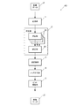
図1は、本発明の実施の形態の画像形成装置Gの構成を機能ごとに示している。
画像形成装置Gは、図1に示すように、制御部11、記憶部12、操作部13、表示部14、通信部15、画像生成部16、画像メモリー17、画像処理装置GA、画像形成部18及び画像読取部19を備えている。
FIG. 1 shows the configuration of the image forming apparatus G according to the embodiment of the present invention for each function.
As shown in FIG. 1, the image forming apparatus G includes a
制御部11は、CPU(Central Processing Unit)、RAM(Random Access Memory)等を備えて構成され、記憶部12から各種プログラムを読み出して実行することにより、各部を制御する。
例えば、制御部11は、画像生成部16により生成され、画像メモリー17に保持された画像データを、画像処理装置GAにより画像処理させて、画像処理後の画像データに基づいて、画像形成部18により用紙上に画像を形成させる。
The
For example, the
記憶部12は、制御部11により読み取り可能なプログラム、プログラムの実行時に用いられるファイル等を記憶している。記憶部12としては、ハードディスク等の大容量メモリーを用いることができる。
The
操作部13は、ユーザーの操作に応じた操作信号を生成し、制御部11に出力する。操作部13としては、キーパッド、表示部14と一体に構成されたタッチパネル等を用いることができる。
The
表示部14は、制御部11の指示にしたがって操作画面等を表示する。表示部14としては、LCD(Liquid Crystal Display)、OELD(Organic Electro Luminescence Display)等を用いることができる。
The
通信部15は、ネットワーク上の外部装置、例えばユーザー端末、サーバー、他の画像形成装置等と通信する。
通信部15は、ネットワークを介してユーザー端末等から、画像を形成する指示内容がページ記述言語(PDL:Page Description Language)で記述されたデータ(以下、PDLデータという)を受信する。
The
The
画像生成部16は、通信部15により受信したPDLデータをラスタライズ処理し、ビットマップ形式の画像データを生成する。画像データは、各画素がC(シアン)、M(マジェンタ)、Y(イエロー)及びK(黒)の4色の階調値を有する。階調値は画像の濃淡を表すデータ値であり、例えば8ビット(bit)のデータ値は0〜255階調の濃淡を表す。
画像生成部16の処理内容は、CPU等のプロセッサーにより画像生成用のプログラムを実行するソフトウェア処理により実現することができる。
The
The processing contents of the
画像生成部16は、画像データとともに、当該画像データの各画素の属性を示す属性データを生成することができる。
例えば、画像生成部16は、ラスタライズ処理時に、PDLデータ中の文字コードの記述にしたがって描画した、かな、アルファベット、数字等の画像の各画素の属性を文字(Text)と決定することができる。また、画像生成部16は、DXF、SVG、WMF等のベクター形式の記述にしたがって描画した多角形、円、罫線等の画像の各画素の属性を図形(Graphics)と決定し、JPEG形式のファイルにより描画した写真画像等の画像の属性を写真(Image)と決定することができる。
The
For example, the
画像メモリー17は、画像生成部16により生成された画像データを一時的に保持するバッファーメモリーである。画像メモリー17としては、DRAM(Dynamic RAM)等を用いることができる。
The
画像処理装置GAは、画像を形成するタイミングに合わせて、画像メモリー17から各ページの画像データを読み出し、画像処理を施す。
画像処理装置GAは、図1に示すように、γ補正部A1、疑似多階調処理部A2及びビーム補正部A3を備えている。
The image processing apparatus GA reads the image data of each page from the
As shown in FIG. 1, the image processing apparatus GA includes a γ correction unit A1, a pseudo multi-gradation processing unit A2, and a beam correction unit A3.
γ補正部A1は、画像形成部18により用紙上に形成する画像の濃度特性が目標とする濃度特性と一致するように、画像データの各画素の階調値を補正する。
The γ correction unit A1 corrects the gradation value of each pixel of the image data so that the density characteristic of the image formed on the paper by the
疑似多階調処理部A2は、γ補正部A1により補正した画像データに疑似多階調処理を施す。疑似多階調処理は、例えば誤差拡散処理、ディザマトリクスを用いたスクリーン処理等である。
なお、文字、線等の画像が2値である場合、ビーム補正部A3による補正が特に有効であるが、これらの画像は、通常、疑似多階調処理の前後で変化が無い。よって、属性データを画像データとともに入力し、属性データが文字又は図形の属性を示す画素は、疑似多階調処理の対象外としてもよい。また、文字、線等の画像が多値である場合も同様にして疑似多階調処理の対象外としてもよい。
The pseudo multi-tone processing unit A2 performs pseudo multi-tone processing on the image data corrected by the γ correction unit A1. The pseudo multi-gradation processing is, for example, error diffusion processing, screen processing using a dither matrix, or the like.
Note that when the image of characters, lines, etc. is binary, correction by the beam correction unit A3 is particularly effective, but these images usually have no change before and after the pseudo multi-gradation processing. Accordingly, the attribute data is input together with the image data, and the pixels whose attribute data indicates the character or graphic attribute may be excluded from the pseudo multi-gradation process. Further, when images of characters, lines, etc. are multi-valued, they may be excluded from the pseudo multi-gradation processing.
ビーム補正部A3は、疑似多階調処理部A2から入力された画像データの各画素の階調値を、レーザービームのビーム位置のずれに起因する濃度差(濃度ムラ)が減るように補正する。
ビーム補正部A3は、レジスタ等のメモリーに各レーザービームのビーム位置のずれ量に応じた補正値を記憶している。
The beam correction unit A3 corrects the gradation value of each pixel of the image data input from the pseudo multi-gradation processing unit A2 so that the density difference (density unevenness) due to the beam position shift of the laser beam is reduced. .
The beam correction unit A3 stores a correction value corresponding to the deviation amount of each laser beam in a memory such as a register.
画像形成部18は、画像処理装置GAにより画像処理された画像データの各画素のC、M、Y及びKの4色の階調値に応じて、4色からなる画像を用紙上に形成する。
具体的には、画像形成部18は、C、M、Y及びKの色ごとに露光部、感光体、現像部等を備えている。画像形成部18は、画像データの各画素の階調値に応じて変調したレーザービームを露光部により照射し、帯電した感光体上を走査して露光し、現像部によりトナーを供給して、露光により感光体上に形成した静電潜像を現像する。このようにして、画像形成部18は、C、M、Y及びKの各色の画像をそれぞれの感光体上に順次形成し、各感光体から中間転写ベルト等の転写体上に重ねて1次転写する。得られたカラー画像を転写体から用紙上へ2次転写した後、用紙を加熱及び加圧して定着処理する。
The
Specifically, the
画像形成部18は、露光時に複数のレーザービームの束であるマルチビームを照射する。
図2は、マルチビームを照射する露光部の概略構成を示している。
露光部は、図2に示すように、レーザー光源部20、コリメーターレンズ31、スリット32、シリンドリカルレンズ33、ポリゴンミラー34、fθレンズ35、シリンドリカルレンズ36、ミラー37及びセンサー38を備えて構成されている。
The
FIG. 2 shows a schematic configuration of an exposure unit that emits multi-beams.
As shown in FIG. 2, the exposure unit includes a laser
レーザー光源部20は、8つの発光素子21L〜28Lを備えている。レーザー光源部20は、各発光素子21L〜28Lを並行して発光させ、8つのレーザービームから構成されるマルチビームを照射する。このマルチビームを、コリメーターレンズ31において平行光束に変え、スリット32において所定のスポット径に整形した後、回転するポリゴンミラー34により、感光体40の表面を走査するように偏向させる。fθレンズ35において、偏向したマルチビームの感光体40上における走査速度を等速化した後、シリンドリカルレンズ36によりマルチビームを感光体40の表面上に結像する。
The laser
各発光素子21L〜28Lは、例えばレーザーダイオードである。各発光素子21L〜28Lは、副走査方向に対して角度θで傾斜し、それぞれの間隔が均一となるように配置されている。副走査方向は、レーザービームの主走査方向と直交する方向である。各発光素子21L〜28Lの傾斜角度θを調整することにより、各発光素子21L〜28Lにより照射されるレーザービームのビーム間隔を調整し、副走査方向における画像の解像度を変更することができる。
Each of the
画像読取部19は、画像形成部18により画像が形成された用紙面を読み取って、ビットマップ形式の読取画像データを生成する。
画像読取部19としては、例えばラインセンサー、エリアセンサー等を使用することができる。
The
For example, a line sensor, an area sensor, or the like can be used as the
上記画像形成装置Gにより用紙上に画像を形成する際、マルチビームの各レーザービームのビーム位置がずれると、画像の濃度変化が生じることがある。
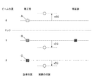
図3Aは、ビーム位置のずれがないときの斜線画像を示している。
図3Aに示すように、マルチビームMとマルチビームMのビーム間隔k1は一定であり、各レーザービームのビーム間隔k2も一定である場合、すなわちk1/(マルチビーム数)=k2となり、ビーム位置が常に等間隔となっている場合、一定濃度の斜線画像を形成することができる。
When an image is formed on a sheet by the image forming apparatus G, if the beam positions of the multi-beam laser beams are shifted, the density of the image may change.
FIG. 3A shows a hatched image when there is no beam position shift.
As shown in FIG. 3A, when the beam interval k1 between the multi-beam M and the multi-beam M is constant and the beam interval k2 of each laser beam is also constant, that is, k1 / (number of multi-beams) = k2, and the beam position Is always at regular intervals, it is possible to form a diagonal image having a constant density.
図3Bは、ビーム位置がずれたときの斜線画像を示している。
図3Bに示すように、マルチビームの位置がずれ、マルチビームMとマルチビームMのビーム間隔k1が広くなると、各マルチビームMの境界上に位置する画像部分の線幅が太くなり、濃度が上昇する。ビーム間隔k1が狭くなる場合は、逆に線幅が短くなり、濃度が低下する。
FIG. 3B shows a hatched image when the beam position is shifted.
As shown in FIG. 3B, when the position of the multi-beam is shifted and the beam interval k1 between the multi-beam M and the multi-beam M is widened, the line width of the image portion located on the boundary between the multi-beams M becomes thicker, and the density is increased. To rise. When the beam interval k1 is narrowed, the line width is conversely shortened and the density is lowered.
形成される斜線画像が1つであれば、このような局所的な濃度変化は目立たないが、複数の斜線画像を一定間隔で形成したとき、局所的な濃度変化が一定周期で生じ、モアレのような濃度ムラとして観察されることがある。
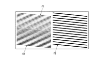
図4は、マルチビームのビーム間隔のずれによって生じたモアレの一例を示している。
図4に示すように、マルチビームのビーム間隔が狭くなって濃度が低下した部分が上下方向に連続して現れている。この濃度が低下した部分は、斜線画像中に周期的に現れ、モアレのような濃度ムラが生じている。
If only one oblique line image is formed, such a local density change is not conspicuous. However, when a plurality of oblique line images are formed at a constant interval, the local density change occurs at a constant period, and moire Such density unevenness may be observed.
FIG. 4 shows an example of moire caused by the deviation of the beam spacing of multi-beams.
As shown in FIG. 4, portions where the beam interval of the multi-beams is narrowed and the density is lowered appear continuously in the vertical direction. The portion where the density is lowered appears periodically in the hatched image, and density unevenness such as moire occurs.
線幅の変動には、特に文字や図形等の画像の輪郭画素を形成するレーザービームのビーム位置のずれが大きく影響する。
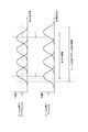
図5は、4つのレーザービームにより4画素幅の線画像を形成したときの各レーザービームの光量分布を示している。
上述のように、電子写真方式では、レーザービームで感光体40上を走査し、その表面電位を変化させてトナーを付着させており、トナーの付着量はレーザービームの光量に比例する。表面電位が変化しトナーが付着し始めるまで、一定量Th以上の光量が必要であり、光量が一定量Thを超える領域がトナーで形成される画像領域となる。図5中、Thに相当する光量を一点鎖線で表している。
The fluctuation of the line width is particularly affected by the deviation of the beam position of the laser beam forming the contour pixels of the image such as characters and figures.
FIG. 5 shows the light amount distribution of each laser beam when a line image having a width of 4 pixels is formed by four laser beams.
As described above, in the electrophotographic system, the surface of the
図5に示すように、ビーム位置がずれたとき、ビーム位置のずれがなくビーム間隔が一定のときと比べて、光量が一定量Thを超える画像領域の幅が異なるため、線画像の線幅が変動する。図5に示す例では、線画像の輪郭を形成するレーザービームのビーム位置が線画像の外側へずれているため、線幅が太くなっているが、逆に線画像の内側へずれれば、線幅が短くなってしまう。なお、位置ずれにより線画像の内部において光量が一定量Thに達しない領域が生じるかもしれないが、このような領域は非常に狭小でトナー散り等によってトナーが付着するため、濃度変化としてほとんど現れない。このように、線画像の線幅は、線画像の内部におけるビーム位置のずれの影響は少なく、線画像の輪郭を形成するレーザービームのビーム位置に依存している。 As shown in FIG. 5, when the beam position is shifted, the width of the image area where the light amount exceeds a certain amount Th is different from that when the beam position is not shifted and the beam interval is constant. Fluctuates. In the example shown in FIG. 5, since the beam position of the laser beam forming the outline of the line image is shifted to the outside of the line image, the line width is thick, but conversely, if shifted to the inside of the line image, The line width will be shortened. Note that there may be a region where the light amount does not reach a certain amount Th inside the line image due to the positional deviation, but such a region is very narrow and the toner adheres due to toner scattering or the like, so that it appears almost as a density change. Absent. As described above, the line width of the line image is less affected by the shift of the beam position inside the line image and depends on the beam position of the laser beam forming the outline of the line image.
画像形成装置Gは、ビーム補正部A3により、レーザービームのビーム位置のずれによる濃度差が減るように、各画素の階調値を補正する。 In the image forming apparatus G, the tone value of each pixel is corrected by the beam correction unit A3 so that the density difference due to the deviation of the beam position of the laser beam is reduced.
〔ビーム補正部〕
図6は、ビーム補正部A3の構成を機能ごとに示している。
ビーム補正部A3は、画像データJ1の各画素を、各画素を中心とする1×5画素単位で入力して補正し、補正した各画素からなる画像データJ2を出力する。画像データJ1及びJ2は、各画素が4ビットすなわち0〜15の階調値を有する。画像データの入力単位は、一般的に観察窓と呼ばれ、観察窓の中心に位置する画素を注目画素という。
図6に示すように、ビーム補正部A3は、変換部1、補正部2、逆変換部3、ノイズ付与部4及びビット調整部5を備えている。
[Beam correction unit]
FIG. 6 shows the configuration of the beam correction unit A3 for each function.
The beam correction unit A3 inputs and corrects each pixel of the image data J1 in units of 1 × 5 pixels centered on each pixel, and outputs image data J2 including the corrected pixels. In the image data J1 and J2, each pixel has 4 bits, that is, a gradation value of 0 to 15. An input unit of image data is generally called an observation window, and a pixel located at the center of the observation window is called a target pixel.
As shown in FIG. 6, the beam correction unit A3 includes a
変換部1は、入力した各画素の4ビットの階調値を9ビットに変換する。ビットの拡張により、階調値を微調整することができ、補正の精度を高めることができる。
また、変換部1は、ビット拡張のための変換と並行して、後述する補正処理による画像データの階調値の変化と、用紙上に形成された画像の濃度の変化の関係が、略リニアな特性となるように、各画素の階調値を変換する。この階調変換によって、補正値の変化量と濃度ムラや線幅の変化量(すなわち、補正値と濃度差)との間に、1:1のリニアな関係を確保することができるようになり、好ましい補正値の算出が容易となる。変換には、ルックアップテーブル(LUT:Look Up Table)を使用することができる。
The
Further, in parallel with the conversion for bit expansion, the
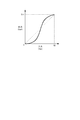
図7は、入力する4ビットの階調値に対し、LUTにより出力する9ビットの階調値の例を示している。
このようなLUTにより、入力した各画素の4ビットの階調値を9ビットに変換することができるとともに、補正値と、補正によって調整できる濃度差との関係が1:1で対応する階調特性となるように、階調値をリニアライズすることができる。
FIG. 7 shows an example of a 9-bit gradation value output by the LUT with respect to an input 4-bit gradation value.
With such an LUT, it is possible to convert the 4-bit gradation value of each input pixel into 9 bits, and the relationship between the correction value and the density difference that can be adjusted by the correction is 1: 1. The gradation value can be linearized so as to be characteristic.
さらに、変換部1は、補正部2の補正により階調値が増えたときのオーバーフローを防ぐため、変換後の9ビットの階調値に最上位のビット位を加えて、10ビットの階調値を出力する。
Furthermore, in order to prevent overflow when the gradation value increases due to correction by the
補正部2は、入力した1×5画素の中心に位置する注目画素の階調値を、レーザービームのビーム位置のずれ量に応じて補正する。
補正部2は、図6に示すように、3つの演算部21及び修正部22を備えている。
The
As shown in FIG. 6, the
3つの演算部21は、入力した1×5画素から、注目画素の前に(後述する図8において上方に)位置する隣接画素を中心とする1×3画素、注目画素を中心とする1×3画素、注目画素の後に(後述する図8において下方に)位置する隣接画素を中心する1×3画素をそれぞれ抽出し、各1×3画素の中心画素の補正後の階調値を算出する。
The three
修正部22は、各演算部21により算出した、注目画素とその前後の隣接画素の補正後の階調値を用いて、注目画素の補正後の階調値を修正する。
The
図8は、補正部2の入力単位である1×5画素を示している。
図8に示すように、補正部2では、画像データJ1の始点の画素を含む1×5画素から終点の画素を含む1×5画素を入力するまで、1×5画素の観察窓の位置を主走査方向xに1画素ずつシフトし、主走査方向xの終端に至ると副走査方向yに1画素シフトして、入力を繰り返す。
FIG. 8
As shown in FIG. 8, in the
各演算部21は、入力した1×5画素から、注目画素とその前後の隣接画素を中心とする1×3画素を抽出し、注目画素とその前後の隣接画素の補正後の階調値を算出する。修正部22は、各演算部21が算出した注目画素とその前後の隣接画素の補正後の階調値を入力して注目画素の補正後の階調値を修正し、修正後の注目画素を補正後の画像データJ2として出力する。なお、1×5画素の中心に位置する画素が注目画素として補正の対象となるため、補正後の画像データJ2の副走査方向yの両端の2ラインは補正がされず元の画素がそのまま出力される。
Each
〔演算〕
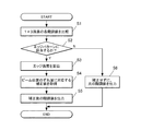
図9は、演算部21の具体的な処理手順を示している。
図9に示すように、演算部21は、入力した1×3画素の各階調値を比較する(ステップS1)。
比較した各階調値が下記エッジパターンPe1及びPe2のいずれかに該当する場合(ステップS2:Y)、演算部21は、1×3画素の中心に位置する画素をオブジェクトの輪郭画素とするエッジを検出し、そのエッジ強度ΔLを算出する(ステップS3)。オブジェクトとは、文字や図形、写真等の前景画像をいう。
〔Calculation〕
FIG. 9 shows a specific processing procedure of the
As shown in FIG. 9, the
When each of the compared gradation values corresponds to one of the following edge patterns Pe1 and Pe2 (step S2: Y), the
図10は、1×3画素のエッジパターンPe1及びPe2を示している。
図10に示すように、1×3画素の各画素A〜Cの階調値をD[A]〜D[C]と表すと、エッジパターンPe1は、D[A]<D[B]≦D[C]を満たすパターンであり、エッジパターンPe2は、D[C]<D[B]≦D[A]を満たすパターンである。エッジパターンPe1に該当する場合、画素Aと画素Bの間にエッジが位置し、エッジパターンPe2に該当する場合、画素Bと画素Cの間にエッジが位置している。いずれのパターンPe1及びPe2においても、画素Bがオブジェクトの輪郭画素である。
FIG. 10 shows edge patterns Pe1 and Pe2 of 1 × 3 pixels.
As shown in FIG. 10, when the gradation values of the pixels A to C of 1 × 3 pixels are expressed as D [A] to D [C], the edge pattern Pe1 has D [A] <D [B] ≦ The edge pattern Pe2 is a pattern that satisfies D [C] <D [B] ≦ D [A]. When it corresponds to the edge pattern Pe1, an edge is located between the pixel A and the pixel B, and when it corresponds to the edge pattern Pe2, an edge is located between the pixel B and the pixel C. In both patterns Pe1 and Pe2, pixel B is the contour pixel of the object.
ビーム位置のずれは線幅が1画素の画像には影響せず、ビーム位置のずれによって濃度変化が発生する可能性があるのは線幅が2画素以上の画像である。エッジパターンPe1及びPe2は、オブジェクトの2画素とオブジェクトの背景の1画素の階調値のパターンであり、このエッジパターンPe1及びPe2に該当する場合のみ補正を行うことにより、線幅が1画素の画像を補正の対象外とすることができる。 The deviation of the beam position does not affect the image having a line width of one pixel, and it is an image having a line width of two pixels or more that may cause a density change due to the deviation of the beam position. The edge patterns Pe1 and Pe2 are tone value patterns of two pixels of the object and one pixel of the background of the object, and correction is performed only when corresponding to the edge patterns Pe1 and Pe2, so that the line width is one pixel. Images can be excluded from correction.
エッジ強度ΔLは、オブジェクトの輪郭画素の階調値と当該輪郭画素に隣接するオブジェクトの背景の画素の階調値との差であるので、エッジパターンPe1の場合は下記式(1)により、エッジパターンPe2の場合は下記式(2)により、エッジ強度ΔLを算出することができる。
(1) ΔL=|D[B]−D[A]|
(2) ΔL=|D[B]−D[C]|
The edge strength ΔL is the difference between the gradation value of the contour pixel of the object and the gradation value of the background pixel of the object adjacent to the contour pixel. Therefore, in the case of the edge pattern Pe1, the following equation (1) In the case of the pattern Pe2, the edge strength ΔL can be calculated by the following equation (2).
(1) ΔL = | D [B] −D [A] |
(2) ΔL = | D [B] −D [C] |
次に、演算部21は、1×3画素の中心に位置する画素Bを形成するレーザービームのビーム位置nを特定し、特定したビーム位置nのずれ量に対応する補正値w[n]をレジスタ等から取得する(ステップS4)。補正値w[n]の大きさは、各レーザービームのビーム位置nの基準位置からのずれ量に比例して決定されている。また、補正値w[n]は、正負の符号を有し、ビーム位置nがオブジェクトの内側へずれる場合は正の符号の補正値w[n]、背景側にずれる場合は負の符号の補正値w[n]が設定されている。
Next, the
演算部21は、取得した補正値w[n]とエッジ強度ΔLとを用いて、1×3画素の中心に位置する画素Bの補正後の階調値D*[B]を算出して出力する(ステップS5)。
演算部21は、下記式(3)により1×3画素の中心に位置する画素Bの補正後の階調値D*[B]を算出することができる。
(3) D*[B]=D[B]+w[n]×ΔL
The
The
(3) D * [B] = D [B] + w [n] × ΔL
図5に示すように、オブジェクトの線幅は、その輪郭画素におけるレーザービームのビーム位置に依存し、そのビーム位置が線画像の背景側へずれれば、線幅が太くなり、逆に線画像の内側へずれれば、線幅が短くなってしまう。エッジ強度ΔLが大きいほど、線幅の変動による濃度変動も大きくなるが、上記式(3)によれば、エッジ強度ΔLに応じて補正量が大きくなるように、元の階調値D[B]に加算する補正値w[n]を調整することができる。 As shown in FIG. 5, the line width of the object depends on the beam position of the laser beam in the contour pixel. If the beam position is shifted to the background side of the line image, the line width becomes thicker. If it is shifted inward, the line width will be shortened. As the edge intensity ΔL increases, the density fluctuation due to the line width fluctuation also increases. However, according to the above equation (3), the original gradation value D [B is set so that the correction amount increases according to the edge intensity ΔL. ] Can be adjusted.
図11は、各画素A、B及びCの階調値のパターンがエッジパターンPe1に該当する場合の補正例を示している。
エッジパターンPe1に該当する場合、画素B及びCは、オブジェクトの画素であり、画素Aはオブジェクトの背景の画素であり、画素A及びB間にエッジが位置している。
図11に示すように、輪郭画素Bの階調値に応じて変調されるレーザービームのビーム位置1が基準位置からオブジェクトの内側へずれると、オブジェクトの線幅が細くなってしまう。
FIG. 11 shows a correction example when the pattern of gradation values of the pixels A, B, and C corresponds to the edge pattern Pe1.
In the case of the edge pattern Pe1, the pixels B and C are object pixels, the pixel A is a background pixel of the object, and an edge is located between the pixels A and B.
As shown in FIG. 11, when the
この場合、演算部21が取得するのは正の補正値w[1]であり、この正の補正値w[1]にエッジ強度ΔLを乗算して得られる正の補正値が、元の階調値D[B]に加算されるため、補正によって画素Bの階調値を増加させることができる。これにより、画素Bにおけるレーザービームの光量が増え、本来の線幅を再現することができる。
In this case, the
逆に、輪郭画素Bのレーザービームのビーム位置1が基準位置から背景側へずれる場合、オブジェクトの線幅が太くなる。この場合、演算部21が取得するのは負の補正値w[1]であり、この負の補正値w[1]にエッジ強度ΔLを乗算して得られる負の補正値が、元の階調値D[B]に加算されるため、補正によって画素Bの階調値を減少させることができる。これにより、画素Bにおけるレーザービームの光量が減り、本来の線幅を再現することができる。
On the contrary, when the
なお、上記ビーム位置nに応じた補正値w[n]は、例えば複数の斜線がマルチビームのビーム数の整数倍で配置されたパターンを、画像形成部18により形成し、当該形成されたパターンにおいて測定された斜線の線幅に基づいて決定することができる。
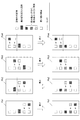
図12は、補正値w[n]の決定に使用できるパターンの一例として、3つのパターンf1〜f3を示している。
パターンf1は、複数の斜線の線幅が4画素、各斜線の間隔がマルチビームのビーム数8と同じ8画素である。
パターンf2は、複数の斜線の線幅が6画素、各斜線の間隔がマルチビームのビーム数8と同じ8画素である。
パターンf3は、複数の斜線の線幅が8画素、各斜線の間隔がマルチビームのビーム数8の2倍の16画素である。
このように、各斜線の間隔をマルチビームのビーム数の整数倍に構成することで、図4に示したような周期的な濃度ムラが見やすいパターンとすることができる。
For the correction value w [n] corresponding to the beam position n, for example, a pattern in which a plurality of oblique lines are arranged by an integral multiple of the number of beams of a multi-beam is formed by the
FIG. 12 shows three patterns f1 to f3 as examples of patterns that can be used to determine the correction value w [n].
In the pattern f1, a plurality of oblique lines have a width of 4 pixels and an interval between the oblique lines is 8 pixels which is the same as the
In the pattern f2, a plurality of diagonal lines have a width of 6 pixels, and the interval between the diagonal lines is 8 pixels, which is the same as the
In the pattern f3, the width of the plurality of oblique lines is 8 pixels, and the interval between the oblique lines is 16 pixels, which is twice the number of multi-beams.
In this manner, by configuring the interval between the oblique lines to be an integral multiple of the number of multi-beams, it is possible to obtain a pattern in which periodic density unevenness as shown in FIG. 4 is easy to see.
いずれか1つのパターンによって補正値w[n]を決定することはできるが、複数のパターンを組み合わせて決定することにより、ビーム位置のずれによる濃度変化をより精度よく、比較的容易に特定することができ、好ましい。
また、斜線の線幅は斜線の濃度に比例するため、線幅の代わりに斜線の濃度を測定してこの濃度に基づいて補正値w[n]を決定してもよい。濃度を測定する場合、高い解像度で読み取ることなく補正値w[n]を決定でき、好ましい。なお、濃度は、斜線を含む一定領域の濃度をその斜線の平均濃度として測定することができるが、これに限られず、斜線の全体的な濃度を測定する一般的な手法を用いることができる。
Although the correction value w [n] can be determined by any one pattern, it is possible to identify the density change due to the deviation of the beam position more accurately and relatively easily by determining a combination of a plurality of patterns. This is preferable.
Further, since the shaded line width is proportional to the shaded line density, instead of the line width, the shaded line density may be measured and the correction value w [n] may be determined based on this density. When measuring the density, the correction value w [n] can be determined without reading at high resolution, which is preferable. The density can be measured by using the density of a certain region including the hatched line as the average density of the hatched line. However, the present invention is not limited to this, and a general method for measuring the overall density of the hatched line can be used.
補正値w[n]の決定時、補正を行わずにパターンを画像形成部18により形成し、斜線の線幅(又は濃度)の変化の傾向を特定し、その傾向に合わせて各ビーム位置の補正値w[n]を決定する。決定した各補正値w[n]を用いて、画像処理装置GAにおいてパターンを補正した後、画像形成部18により形成して、斜線の線幅(又は濃度)の変化の傾向を特定し、この傾向に合わせて各ビーム位置の補正値w[n]を修正する。この補正値w[n]の修正を、補正後の斜線の線幅(又は濃度)が本来の線幅(又は濃度)に一致するまで(または、周期ムラが見えにくくなるか、極小化するまで)繰り返せばよい。
When the correction value w [n] is determined, a pattern is formed by the
上記のように、補正値w[n]の修正を繰り返して最適化してもよいが、いくつかの補正値w[n]で補正したパターンを形成して、補正後の斜線の線幅(又は濃度)が本来の線幅(又は濃度)に近い(または、周期ムラの見えにくい)補正値w[n]を選択するようにしてもよい。 As described above, the correction of the correction value w [n] may be repeated and optimized, but a pattern corrected with several correction values w [n] is formed, and the line width of the oblique line after correction (or A correction value w [n] may be selected in which (density) is close to the original line width (or density) (or it is difficult to see periodic unevenness).
一方、いずれのエッジパターンPe1及びPe2にも該当しない場合(ステップS2:N)、演算部21は補正を行わずに、1×3画素の中心に位置する画素を元の階調値のまま出力する(ステップS6)。
On the other hand, when none of the edge patterns Pe1 and Pe2 correspond (step S2: N), the
演算部21は、画像データの各画素の属性に応じて、補正を行って補正後の階調値を出力するか、補正を行わずに元の階調値を出力するかを切り替えることができる。各画素の属性は、画像データとともに生成される属性データにより判別することができる。
例えば、演算部21は、属性が写真の画素を補正対象外とし、属性が文字又は図形の画素を補正対象として決定することができる。写真の画像領域は、ノイズ除去のためにローパスフィルター処理等が施されてオブジェクトと背景のコントラスト差が明瞭でなく、エッジとして検出しにくいことがある。また、オブジェクトの濃度が平坦な領域が少なく、ビーム位置のずれによる濃度変動がもともと目立ちにくく補正の効果が小さい反面、補正(例えば、中間調の写真画像は網掛け処理(スクリーン処理)で疑似多階調処理される場合が多いが、網掛け処理によって生じた、本来の画像とは関係の無い、局所的な階調差をエッジとして処理する補正)により意図しない濃度変動が生じることがあるため、写真の属性の画素を補正対象外とすることにより、新たな画質劣化を防止することができる。
The
For example, the
〔修正〕
修正部22は、注目画素の補正後の階調値が最大値を超える場合は超えた分を切り捨てて最大値とし、注目画素にエッジを介して隣接する隣接画素の補正後の階調値が最大値を超える場合は、超えた分の階調値を注目画素の階調値に加算する修正を行う。
具体的には、修正部22は、図8に示すように、補正部2に入力した1×5画素のうち、中央の3画素については各演算部21から出力された補正後の3画素を入力して1×5画素を再構成する。再構成した1×5画素の両端の2画素は元の画素のままである。修正部22は、1×5画素の各階調値を比較し、各階調値のパターンが修正対象のパターンに該当するか否かを判断する。
[Correction]
When the corrected gradation value of the target pixel exceeds the maximum value, the
Specifically, as illustrated in FIG. 8, the
図13は、修正対象のパターンPb1〜Pb4を示している。
図13に示すように、修正対象のパターンPb1〜Pb4は、注目画素の階調値か、注目画素とエッジを介して隣接する画素の階調値が、補正によって最大値を超えたパターンである。修正部22は、パターンPb1、Pb2、Pb3、Pb4の順に、該当するか否かを判断する。
FIG. 13 shows patterns Pb1 to Pb4 to be corrected.
As shown in FIG. 13, the correction target patterns Pb1 to Pb4 are patterns in which the gradation value of the target pixel or the gradation value of the pixel adjacent to the target pixel through the edge exceeds the maximum value by the correction. . The correcting
修正対象のパターンPb1〜Pb4のいずれかに該当する場合、修正部22は注目画素の補正後の階調値を修正して出力する。図13に示すように、修正対象のパターンPb1又はPb4に該当する場合、注目画素の階調値が最大値を超えているので、修正部22は最大値を超えた分の階調値を切り捨てて、注目画素の階調値を最大値とする修正を行う。また、修正対象のパターンPb2又はPb3に該当する場合、注目画素とエッジを介して隣接する画素の階調値が最大値を超えているので、修正部22は最大値を超えた分の階調値を、注目画素の階調値に加算する修正を行う。
If any of the correction target patterns Pb1 to Pb4 is applicable, the
修正部22による修正を行うか否かは、任意に設定できるようにしてもよい。
例えば、通常は修正を行う設定として、温度や湿度等の環境が大きく変化し、一時的に好ましい補正を実施できなくなった場合に、修正を行わない設定することができる。
Whether or not the correction by the
For example, as a setting for correction, it is possible to set the correction not to be performed when an environment such as temperature and humidity changes greatly and it becomes impossible to perform a preferable correction temporarily.
逆変換部3は、補正部2により補正した各画素の階調値を、変換部1により変換した階調特性と逆特性の階調特性となるように、LUTを使用して変換する。補正部2から出力される10ビットの階調値のうち、最上位の1ビットはオーバーフロー用のビット位であり、修正部22による修正によってオーバーフローは解消しているため、逆変換部3は、10ビットのうち下位9ビットを抽出して変換する。なお、上述のように修正部22による修正を行わない設定とした場合は、オーバーフローした10ビットが逆変換部3に引き渡されることになるため、逆変換に先立ち、オーバーフローした10ビットを9ビットの最大値に変換(クリップ)し、下位9ビットを抽出した後、変換する。
The
図14は、入力した9ビットの階調値に対し、LUTにより出力する9ビットの階調値の例を示している。
このようなLUTにより、入力した階調値と出力する階調値の対応関係を元に戻すことができる。
FIG. 14 shows an example of the 9-bit gradation value output by the LUT with respect to the input 9-bit gradation value.
With such an LUT, the correspondence between the input gradation value and the output gradation value can be restored.
ノイズ付与部4は、逆変換部3から出力された各画素の9ビットの階調値に、5ビットのノイズ値を加算して、ノイズを付与する。
ノイズの付与により、補正後に階調値のビット数を減らす場合でも、補正値の加算による微小な階調値の変化を再現することができる。
ノイズ付与により階調値が9ビットからオーバーフローする可能性がある場合は、最上位のビット位を加えて10ビットの階調値としてからノイズ値を加算し、加算後に最上位ビットを削除して下位9ビットの階調値を出力すればよい。
The noise adding unit 4 adds noise by adding a 5-bit noise value to the 9-bit gradation value of each pixel output from the
Even when the number of bits of the gradation value is reduced after the correction due to the addition of noise, a minute change in the gradation value due to the addition of the correction value can be reproduced.
If there is a possibility that the gradation value overflows from 9 bits due to noise, add the most significant bit to make the 10-bit gradation value, add the noise value, and delete the most significant bit after the addition It is only necessary to output the lower 9 bits of the gradation value.
ノイズ付与部4は、ディザマトリクスを用いてノイズ値を付与することができる。具体的には、ノイズ付与部4は、5ビットすなわち0〜31の閾値が各画素に設定された32画素のディザマトリクスを用意し、対応する位置にある画像データの各画素の画素値に閾値を合算する。ディザマトリクスを使用する場合、疑似的に多階調を再現することもでき、好ましい。 The noise imparting unit 4 can impart a noise value using a dither matrix. Specifically, the noise applying unit 4 prepares a dither matrix of 32 pixels in which a threshold value of 5 bits, that is, 0 to 31 is set for each pixel, and sets the threshold value to the pixel value of each pixel of the image data at the corresponding position. Add together. When a dither matrix is used, it is possible to reproduce a multi-tone in a pseudo manner, which is preferable.
なお、ディザマトリクスを使用する場合、マルチビームのビーム間隔のずれによるモアレと、ディザマトリクスの周期性が干渉しないように、ディザマトリクスの形状、サイズ等を選択することが好ましい。例えば、マルチビームのビーム数の整数倍とならないように、ディザマトリクスの副走査方向のサイズを選択すればよい。また、形状及びサイズが異なる複数のディザマトリクスを組み合わせたスーパーセルを使用してもよい。 When a dither matrix is used, it is preferable to select the shape, size, etc. of the dither matrix so that the moire caused by the deviation of the beam spacing of the multi-beams does not interfere with the periodicity of the dither matrix. For example, the size of the dither matrix in the sub-scanning direction may be selected so as not to be an integral multiple of the number of beams of the multi-beam. Also, a supercell combining a plurality of dither matrices having different shapes and sizes may be used.
ノイズ付与部4は、ノイズ値として、乱数発生装置等により出力された異なる数値を取得して付与することもできる。
視認性の高いゆらぎを避け、粒状性の劣化を防止するためには、ノイズ値は、比較的高い空間周波数成分を中心としたブルーノイズのノイズ値であることが好ましい。
The noise imparting unit 4 can also obtain and impart different numerical values output by a random number generator or the like as the noise value.
In order to avoid fluctuations with high visibility and prevent deterioration of graininess, the noise value is preferably a blue noise noise value centered on a relatively high spatial frequency component.
ビット調整部5は、ノイズ付与部4から出力された画像データの各画素の9ビットの階調値をビットシフトして、上位4ビットを抽出して出力する。
The
以上のように、本実施の形態の画像形成装置Gは、画像データの各画素の階調値を、マルチビームの各レーザービームのビーム位置のずれによる濃度差が減るように補正するビーム補正部A3と、ビーム補正部A3により補正した各画素の補正後の階調値に応じて変調されたマルチビームを照射して感光体上を走査し、複数ラインの露光を並行して行う画像形成部18と、を備えている。ビーム補正部A3は、画像データの各画素と各画素の隣接画素間において、オブジェクトのエッジを検出してそのエッジ強度を算出し、各画素の階調値に応じて照射するレーザービームのビーム位置のずれ量に対応する補正値と、算出したエッジ強度とを用いて、各画素の補正後の階調値を算出する演算部21を備えている。
As described above, the image forming apparatus G according to the present embodiment corrects the gradation value of each pixel of the image data so as to reduce the density difference due to the beam position shift of each laser beam of the multi-beam. A3 and an image forming unit that scans the photosensitive member by irradiating a multi-beam modulated according to the corrected gradation value of each pixel corrected by the beam correcting unit A3, and performs exposure of a plurality of lines in parallel 18. The beam correction unit A3 detects the edge of the object between each pixel of the image data and the adjacent pixel of each pixel, calculates the edge intensity, and the beam position of the laser beam irradiated according to the gradation value of each pixel An
各画素を注目画素として、注目画素とその隣接画素間におけるエッジを検出して注目画素の補正後の階調値を順次算出するため、各画素がオブジェクトの輪郭画素か否かによって補正の内容を切り替える必要がない。したがって、画一的な処理内容で安定した補正を行うことが可能である。
また、レーザービームのビーム位置のずれ量だけでなく、濃度変動への影響が大きいエッジ強度を用いて補正後の階調値を算出するため、補正の精度を向上させることができる。
Since each pixel is a target pixel and an edge between the target pixel and its neighboring pixels is detected and the corrected tone value of the target pixel is calculated sequentially, the correction contents are determined depending on whether or not each pixel is a contour pixel of the object. There is no need to switch. Therefore, stable correction can be performed with uniform processing contents.
In addition, since the corrected gradation value is calculated using not only the amount of deviation of the laser beam position but also the edge intensity that has a large influence on the density variation, the correction accuracy can be improved.
〔変形例1〕
各レーザービームの走査線は、シリンドリカルレンズ36等の光学系のゆがみや、ポリゴンミラー34のミラー面のゆがみ、偏心等に起因して水平線とならずに湾曲又は傾斜することがある。この場合、演算部21が、各レーザービームのビーム位置だけでなく主走査方向の位置に応じて使用する補正値を調整することにより、主走査方向の位置による補正の過不足を減らすことができる。
[Modification 1]
The scanning line of each laser beam may be curved or inclined without becoming a horizontal line due to distortion of the optical system such as the
図15は、主走査方向の位置に応じた補正値の調整例を示している。
図15に示すように、演算部21は、ビーム位置nに応じた補正値w[n]を初期値として、主走査方向xにL画素シフトするごとに調整値d1〜d4を加算することにより、補正値w[n]を調整することができる。調整値d1〜d4は、レーザービームの走査線の勾配に応じて、最大補正量の範囲内で定められている。勾配を決定する3つの変曲点は任意に設定することができる。調整値d1〜d4を加算して補正値w[n]が最大補正量を超える場合は、補正値w[n]を最大補正量とする。図15において下向きの矢印で表す調整値d1及びd2は負の調整値であり、補正値w[n]を減らす。また、上向きの矢印で表す調整値d3及びd4は正の調整値であり、補正値w[n]を増やす。
ここでは主走査方向の位置に応じた補正値の調整方法として、3つの変曲点と、各々の間の補正値の変化量(勾配)を規定したが、これに限られるものではない。たとえば、上記変曲点に相当する位置と、主走査方向xの始端及び終端の位置のそれぞれの補正値を保持しておき、それらの中間位置の補正値は、当該中間位置の前後の位置における補正値を線形補間して算出するようにしてもよい。
FIG. 15 shows an example of adjusting the correction value according to the position in the main scanning direction.
As shown in FIG. 15, the
Here, three inflection points and the amount of change (gradient) in the correction value between each of the inflection points are defined as a method for adjusting the correction value in accordance with the position in the main scanning direction, but the present invention is not limited to this. For example, the correction values of the position corresponding to the inflection point and the start and end positions in the main scanning direction x are held, and the correction values of these intermediate positions are the positions before and after the intermediate position. The correction value may be calculated by linear interpolation.
レーザービームの走査線の勾配は、ポリゴンミラー34の各ミラー面によって異なるため、各ミラー面に応じて補正値を調整することもできる。
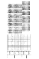
図16は、マルチビームのレーザービーム数が4つ、ポリゴンミラーのミラー面の数が3つの場合の補正値の調整例を示している。
図16に示すように、ミラー面1では4つのレーザービームのそれぞれに対応する補正値セット01〜04が定められている。同様に、ミラー面2では補正値セット05〜08、ミラー面3では補正値セット09〜12が定められている。各補正値セット01〜12は、各レーザービームのビーム位置nに対応する補正値w[n]を初期値として、初期値と初期値に加算する調整値d1〜d4を含む。
各ミラー面1〜3による1周期目の走査を終えると、2周期目からは1周期目と同様に各ミラー面1〜3に対応する補正値セット01〜12を使用すればよい。
Since the gradient of the scanning line of the laser beam varies depending on each mirror surface of the
FIG. 16 shows an example of adjusting the correction value when the number of multi-beam laser beams is four and the number of mirror surfaces of the polygon mirror is three.
As shown in FIG. 16, correction value sets 01 to 04 corresponding to each of the four laser beams are defined on the
When the scanning of the first cycle by each
上記実施の形態は本発明の好適な一例であり、これに限定されない。本発明の主旨を逸脱しない範囲で適宜変更可能である。
例えば、制御部11がプログラムを読み取ることにより、上記ビーム補正部A3の処理手順を制御部11により実行させることもできる。また、画像形成装置Gに限らず、汎用のPC等のコンピューターにより当該プログラムを読み取らせて、上記処理手順を実行させることもできる。
プログラムのコンピューター読み取り可能な媒体としては、ROM、フラッシュメモリー等の不揮発性メモリー、CD-ROM等の可搬型記録媒体を適用することが可能である。また、プログラムのデータを、通信回線を介して提供する媒体として、キャリアウエーブ(搬送波)も適用される。
The above embodiment is a preferred example of the present invention, and the present invention is not limited to this. Modifications can be made as appropriate without departing from the spirit of the present invention.
For example, when the
As a computer-readable medium for the program, a non-volatile memory such as a ROM and a flash memory, and a portable recording medium such as a CD-ROM can be applied. A carrier wave is also used as a medium for providing program data via a communication line.
G 画像形成装置
11 制御部
18 画像形成部
20 レーザー光源部
34 ポリゴンミラー
40 感光体
GA 画像処理装置
A3 ビーム補正部
1 変換部
2 補正部
21 演算部
22 修正部
3 逆変換部
4 ノイズ付与部
5 ビット調整部
G
Claims (18)
前記ビーム補正部は、前記画像データの各画素と各画素の隣接画素間において、オブジェクトのエッジを検出してそのエッジ強度を算出し、前記各画素の階調値に応じて照射するレーザービームのビーム位置のずれ量に対応する補正値と、前記算出したエッジ強度とを用いて、各画素の補正後の階調値を算出する演算部を備えることを特徴とする画像処理装置。 A beam correction unit that corrects the gradation value of each pixel of the image data so as to reduce the density difference due to the beam position shift of each laser beam of the multi-beam,
The beam correction unit detects an edge of an object between each pixel of the image data and an adjacent pixel of the pixel, calculates an edge intensity thereof, and applies a laser beam to be irradiated according to a gradation value of the pixel. An image processing apparatus comprising: an arithmetic unit that calculates a corrected gradation value of each pixel using a correction value corresponding to a deviation amount of a beam position and the calculated edge intensity.
前記演算部により補正後の階調値を算出する前に、前記補正値と前記濃度差が1:1で対応する階調特性となるように、各画素の階調値を変換する変換部と、
前記演算部により補正後の階調値を算出した後に、前記変換部により変換した階調特性と逆特性の階調特性となるように、前記補正後の階調値を変換する逆変換部と、
を備えることを特徴とする請求項1に記載の画像処理装置。 The beam correction unit is
A conversion unit that converts the gradation value of each pixel so that the correction value and the density difference have a corresponding gradation characteristic of 1: 1 before calculating the corrected gradation value by the arithmetic unit; ,
An inverse conversion unit that converts the corrected gradation value so that the gradation characteristic is opposite to the gradation characteristic converted by the conversion unit after calculating the corrected gradation value by the arithmetic unit; ,
The image processing apparatus according to claim 1, further comprising:
前記各画素の補正後の階調値が階調値の最大値を超える場合、超えた分の階調値を切り捨てて最大値とし、前記各画素と前記エッジを介して隣接する隣接画素の補正後の階調値が階調値の最大値を超える場合、超えた分の階調値を前記各画素の補正後の階調値に加算する修正部を備えることを特徴とする請求項1又は2に記載の画像処理装置。 The beam correction unit is
If the corrected gradation value of each pixel exceeds the maximum gradation value, the excess gradation value is rounded down to the maximum value, and correction of adjacent pixels adjacent to each pixel through the edge is performed. 2. The correction unit according to claim 1, further comprising: a correction unit that adds the excess gradation value to the corrected gradation value of each pixel when the subsequent gradation value exceeds a maximum gradation value. 2. The image processing apparatus according to 2.
前記補正後の階調値にノイズ値を加算するノイズ付与部を備えることを特徴とする請求項1〜3のいずれか一項に記載の画像処理装置。 The beam correction unit is
The image processing apparatus according to claim 1, further comprising a noise applying unit that adds a noise value to the corrected gradation value.
前記ビーム補正部により補正した各画素の補正後の階調値に応じて変調されたマルチビームを照射して感光体上を走査し、複数ラインの露光を並行して行う画像形成部と、を備え、
前記ビーム補正部は、前記画像データの各画素と各画素の隣接画素間において、オブジェクトのエッジを検出してそのエッジ強度を算出し、前記各画素の階調値に応じて照射するレーザービームのビーム位置のずれ量に対応する補正値と、前記算出したエッジ強度とを用いて、各画素の補正後の階調値を算出する演算部を備えることを特徴とする画像形成装置。 A beam correction unit that corrects the gradation value of each pixel of the image data so as to reduce the density difference due to the beam position shift of each laser beam of the multi-beam;
An image forming unit that scans the photosensitive member by irradiating a multi-beam modulated according to the gradation value after correction of each pixel corrected by the beam correcting unit, and performs exposure of a plurality of lines in parallel; Prepared,
The beam correction unit detects an edge of an object between each pixel of the image data and an adjacent pixel of the pixel, calculates an edge intensity thereof, and applies a laser beam to be irradiated according to a gradation value of the pixel. An image forming apparatus comprising: an arithmetic unit that calculates a corrected gradation value of each pixel using a correction value corresponding to a deviation amount of a beam position and the calculated edge intensity.
前記演算部により補正後の階調値を算出する前に、前記補正値と前記濃度差が1:1で対応する階調特性となるように、各画素の階調値を変換する変換部と、
前記演算部により補正後の階調値を算出した後に、前記変換部により変換した階調特性と逆特性の階調特性となるように、前記補正後の階調値を変換する逆変換部と、
を備えることを特徴とする請求項7に記載の画像形成装置。 The beam correction unit includes:
A conversion unit that converts the gradation value of each pixel so that the correction value and the density difference have a corresponding gradation characteristic of 1: 1 before calculating the corrected gradation value by the arithmetic unit; ,
An inverse conversion unit that converts the corrected gradation value so that the gradation characteristic is opposite to the gradation characteristic converted by the conversion unit after calculating the corrected gradation value by the arithmetic unit; ,
The image forming apparatus according to claim 7, further comprising:
前記各画素の補正後の階調値が階調値の最大値を超える場合、超えた分の階調値を切り捨てて最大値とし、前記各画素と前記エッジを介して隣接する隣接画素の補正後の階調値が階調値の最大値を超える場合、超えた分の階調値を前記各画素の補正後の階調値に加算する修正部を備えることを特徴とする請求項7又は8に記載の画像形成装置。 The beam correction unit is
If the corrected gradation value of each pixel exceeds the maximum gradation value, the excess gradation value is rounded down to the maximum value, and correction of adjacent pixels adjacent to each pixel through the edge is performed. 8. The correction unit according to claim 7, further comprising: a correction unit that adds the excess gradation value to the corrected gradation value of each pixel when the subsequent gradation value exceeds a maximum value of the gradation value. The image forming apparatus according to 8.
前記補正後の階調値にノイズ値を加算するノイズ付与部を備えることを特徴とする請求項7〜9のいずれか一項に記載の画像形成装置。 The beam correction unit is
The image forming apparatus according to claim 7, further comprising a noise applying unit that adds a noise value to the corrected gradation value.
(a)画像データの各画素の階調値を、マルチビームの各レーザービームのビーム位置のずれによる濃度差が減るように補正するステップを実行させるためのプログラムであって、
前記ステップ(a)は、
(a1)前記画像データの各画素と各画素の隣接画素間において、オブジェクトのエッジを検出してそのエッジ強度を算出し、前記各画素の階調値に応じて照射するレーザービームのビーム位置のずれ量に対応する補正値と、前記算出したエッジ強度とを用いて、各画素の補正後の階調値を算出するステップを含むことを特徴とするプログラム。 On the computer,
(A) A program for executing a step of correcting a gradation value of each pixel of image data so that a density difference due to a beam position shift of each laser beam of a multi-beam is reduced,
The step (a)
(A1) An edge of an object is detected between each pixel of the image data and an adjacent pixel of each pixel, the edge intensity is calculated, and the beam position of the laser beam irradiated according to the gradation value of each pixel is calculated. A program comprising a step of calculating a corrected gradation value of each pixel using a correction value corresponding to a shift amount and the calculated edge strength.
(a2)前記補正後の階調値を算出する前に、前記補正値と前記濃度差が1:1で対応する階調特性となるように、各画素の階調値を変換するステップと、
(a3)前記補正後の階調値を算出した後に、前記変換部により変換した階調特性と逆特性の階調特性となるように、前記補正後の階調値を変換するステップと、
を含むことを特徴とする請求項13に記載のプログラム。 The step (a)
(A2) before calculating the corrected gradation value, converting the gradation value of each pixel so that the correction value and the density difference have a corresponding gradation characteristic of 1: 1;
(A3) After calculating the corrected gradation value, converting the corrected gradation value so that the gradation characteristic is opposite to the gradation characteristic converted by the conversion unit;
The program according to claim 13, comprising:
(a4)前記各画素の補正後の階調値が階調値の最大値を超える場合、超えた分の階調値を切り捨てて最大値とし、前記各画素と前記エッジを介して隣接する隣接画素の補正後の階調値が階調値の最大値を超える場合、超えた分の階調値を前記各画素の補正後の階調値に加算するステップを含むことを特徴とする請求項13又は14に記載のプログラム。 The step (a)
(A4) When the corrected gradation value of each pixel exceeds the maximum gradation value, the excess gradation value is rounded down to the maximum value, and adjacent to each pixel via the edge 2. The method according to claim 1, further comprising the step of adding the gradation value after the correction to the corrected gradation value of each pixel when the gradation value after the correction of the pixel exceeds the maximum value of the gradation value. The program according to 13 or 14.
(a5)前記補正後の階調値にノイズ値を加算するステップを含むことを特徴とする請求項13〜15のいずれか一項に記載のプログラム。 The step (a)
(A5) The program according to any one of claims 13 to 15, further comprising a step of adding a noise value to the corrected gradation value.
Priority Applications (2)
| Application Number | Priority Date | Filing Date | Title |
|---|---|---|---|
| JP2016179180A JP6729227B2 (en) | 2016-09-14 | 2016-09-14 | Image processing apparatus, image forming apparatus and program |
| US15/701,816 US10235610B2 (en) | 2016-09-14 | 2017-09-12 | Image processing apparatus which corrects a gray level of each pixel in image data, image forming apparatus and computer-readable medium |
Applications Claiming Priority (1)
| Application Number | Priority Date | Filing Date | Title |
|---|---|---|---|
| JP2016179180A JP6729227B2 (en) | 2016-09-14 | 2016-09-14 | Image processing apparatus, image forming apparatus and program |
Publications (2)
| Publication Number | Publication Date |
|---|---|
| JP2018043403A true JP2018043403A (en) | 2018-03-22 |
| JP6729227B2 JP6729227B2 (en) | 2020-07-22 |
Family
ID=61559897
Family Applications (1)
| Application Number | Title | Priority Date | Filing Date |
|---|---|---|---|
| JP2016179180A Active JP6729227B2 (en) | 2016-09-14 | 2016-09-14 | Image processing apparatus, image forming apparatus and program |
Country Status (2)
| Country | Link |
|---|---|
| US (1) | US10235610B2 (en) |
| JP (1) | JP6729227B2 (en) |
Families Citing this family (2)
| Publication number | Priority date | Publication date | Assignee | Title |
|---|---|---|---|---|
| JP7223247B2 (en) * | 2018-09-27 | 2023-02-16 | 株式会社リコー | image forming device |
| JP2021030598A (en) * | 2019-08-26 | 2021-03-01 | 京セラドキュメントソリューションズ株式会社 | Image formation apparatus, image formation method and image formation program |
Family Cites Families (11)
| Publication number | Priority date | Publication date | Assignee | Title |
|---|---|---|---|---|
| JP3741813B2 (en) | 1997-01-08 | 2006-02-01 | 富士写真フイルム株式会社 | Image forming apparatus |
| TW384612B (en) * | 1998-08-19 | 2000-03-11 | Acer Peripherals Inc | Image processing system and method capable of converting gray-level images into binary images |
| JP2000238329A (en) | 1999-02-24 | 2000-09-05 | Fuji Xerox Co Ltd | Image-forming apparatus |
| US7400766B1 (en) * | 2004-02-19 | 2008-07-15 | The United States Of America As Represented By The Administrator Of The National Aeronautics And Space Administration | Image edge extraction via fuzzy reasoning |
| JP2009118378A (en) | 2007-11-09 | 2009-05-28 | Sharp Corp | Image forming device, image forming method, image forming program and computer-readable recording medium for recording the program |
| JP4849118B2 (en) * | 2008-12-04 | 2012-01-11 | コニカミノルタビジネステクノロジーズ株式会社 | Image processing apparatus, image conversion method, and computer program |
| JP2011239090A (en) * | 2010-05-07 | 2011-11-24 | Konica Minolta Business Technologies Inc | Image processing apparatus, conversion method, and computer program |
| CN104217416B (en) * | 2013-05-31 | 2017-09-15 | 富士通株式会社 | Gray level image processing method and its device |
| JP6213182B2 (en) | 2013-11-21 | 2017-10-18 | コニカミノルタ株式会社 | Image forming apparatus and density unevenness correction method |
| JP6167950B2 (en) * | 2014-03-14 | 2017-07-26 | 富士ゼロックス株式会社 | Image processing apparatus, image forming system, and image forming apparatus |
| JP6486082B2 (en) * | 2014-11-27 | 2019-03-20 | キヤノン株式会社 | Image processing apparatus, image processing method, and program |
-
2016
- 2016-09-14 JP JP2016179180A patent/JP6729227B2/en active Active
-
2017
- 2017-09-12 US US15/701,816 patent/US10235610B2/en active Active
Also Published As
| Publication number | Publication date |
|---|---|
| US20180074431A1 (en) | 2018-03-15 |
| JP6729227B2 (en) | 2020-07-22 |
| US10235610B2 (en) | 2019-03-19 |
Similar Documents
| Publication | Publication Date | Title |
|---|---|---|
| JP4771569B2 (en) | Distortion correction method and distortion correction apparatus | |
| JP6512838B2 (en) | Image processing apparatus, image processing method and program | |
| US9146514B2 (en) | Image forming apparatus and image forming method for correcting registration deviation | |
| US8786907B2 (en) | Image processing apparatus, control method of image processing apparatus, image forming apparatus, and storage medium | |
| JP6213182B2 (en) | Image forming apparatus and density unevenness correction method | |
| JP6729227B2 (en) | Image processing apparatus, image forming apparatus and program | |
| US10788433B2 (en) | Correction value calculation method, image forming apparatus, program, and inspection image | |
| JP4618333B2 (en) | Image forming apparatus, gradation correction method, and gradation correction program | |
| JP2018149776A (en) | Image processing apparatus, image forming apparatus and program | |
| JP4544280B2 (en) | Image processing apparatus, image forming apparatus, and image processing program | |
| JP4496897B2 (en) | Printing apparatus and gradation correction method thereof | |
| JP6029714B2 (en) | Apparatus and method for handling image data | |
| JP4775909B2 (en) | Image processing apparatus, image processing method, program, recording medium, and image forming apparatus | |
| US10477067B2 (en) | Image forming apparatus, image forming method, and storage medium | |
| JP2011019185A (en) | Image forming device | |
| JP2004242085A (en) | Device and method for processing image | |
| JP2017085295A (en) | Image processing apparatus and control method | |
| JP6504773B2 (en) | IMAGE PROCESSING APPARATUS, IMAGE PROCESSING METHOD, AND PROGRAM | |
| JP6604172B2 (en) | Image forming apparatus and line width adjusting method | |
| JP2011119904A (en) | Image processing apparatus, image forming apparatus, and image processing method | |
| JP4759531B2 (en) | Image processing apparatus and image forming apparatus | |
| JP5595345B2 (en) | Image processing apparatus, image forming apparatus, and image processing method | |
| JP2013021620A (en) | Image processing method and apparatus of the same | |
| JP2007201689A (en) | Image processing apparatus, method, and program for implementing halftone processing | |
| JP2007208657A (en) | Gradation correction apparatus |
Legal Events
| Date | Code | Title | Description |
|---|---|---|---|
| A621 | Written request for application examination |
Free format text: JAPANESE INTERMEDIATE CODE: A621 Effective date: 20190523 |
|
| A131 | Notification of reasons for refusal |
Free format text: JAPANESE INTERMEDIATE CODE: A131 Effective date: 20200324 |
|
| A977 | Report on retrieval |
Free format text: JAPANESE INTERMEDIATE CODE: A971007 Effective date: 20200325 |
|
| A521 | Request for written amendment filed |
Free format text: JAPANESE INTERMEDIATE CODE: A523 Effective date: 20200519 |
|
| TRDD | Decision of grant or rejection written | ||
| A01 | Written decision to grant a patent or to grant a registration (utility model) |
Free format text: JAPANESE INTERMEDIATE CODE: A01 Effective date: 20200602 |
|
| A61 | First payment of annual fees (during grant procedure) |
Free format text: JAPANESE INTERMEDIATE CODE: A61 Effective date: 20200615 |
|
| R150 | Certificate of patent or registration of utility model |
Ref document number: 6729227 Country of ref document: JP Free format text: JAPANESE INTERMEDIATE CODE: R150 |