JP2018043302A - Polishing gun device - Google Patents
Polishing gun device Download PDFInfo
- Publication number
- JP2018043302A JP2018043302A JP2016177760A JP2016177760A JP2018043302A JP 2018043302 A JP2018043302 A JP 2018043302A JP 2016177760 A JP2016177760 A JP 2016177760A JP 2016177760 A JP2016177760 A JP 2016177760A JP 2018043302 A JP2018043302 A JP 2018043302A
- Authority
- JP
- Japan
- Prior art keywords
- diffuser
- nozzle
- blast material
- gun body
- gun
- Prior art date
- Legal status (The legal status is an assumption and is not a legal conclusion. Google has not performed a legal analysis and makes no representation as to the accuracy of the status listed.)
- Granted
Links
Images


Abstract
Description
この発明は、既設の建造物に締結されたボルトやナット、リベット等の錆や塗膜等を研磨する研磨ガン装置に関する。 The present invention relates to a polishing gun apparatus for polishing rust, coating film, and the like of bolts, nuts, rivets and the like fastened to an existing building.
この種の研磨ガン装置として、図3,4に示したものが従来から知られている。
従来の研磨ガン装置は、図3に示すように、ブラスト材が加圧タンク1からブラストホース2を経て圧送されるとともに、このブラストホース2の先端に設けられたノズル3から上記ブラスト材が噴出され、建造物4に締結されたボルト等を研磨する。このように、上記ノズル3から噴出されたブラスト材が上記ボルト等に衝突するときの衝撃力で錆や塗膜等を削り取る。
As this type of polishing gun apparatus, those shown in FIGS. 3 and 4 are conventionally known.
In the conventional polishing gun apparatus, as shown in FIG. 3, the blast material is pumped from the pressurized tank 1 through the blast hose 2 and the blast material is ejected from the
上記ボルト等や建造物4に当たって勢いを失ったブラスト材は、粉塵や研削された塗膜片等とともにバキュームホース5で吸引されて回収タンク6に送られる。この回収タンク6に送られたブラスト材は、粉塵や塗膜片等と分別され、上記加圧タンク1に回収され、上記粉塵や塗膜片等はダストコレクター7に捕集される。
The blasting material that has lost its momentum by hitting the bolts or the building 4 is sucked by the
また、ブラスト材を噴出させる上記ノズル3は、図4に示すように、耐摩耗性の合成ゴムからなるガン本体8の一方の筒部8aにぴったりとはめられている。
このガン本体8は、上記一方の筒部8aとは反対側に他方の筒部8bを設けるとともに、この筒部8bの内径を、上記一方の筒部8aの内径よりも大きくしている。そして、上記ガン本体8は、一方の筒部8aと他方の筒部8bとのほぼ境界部分に吸引筒部8cを分岐させ、この吸引筒部8cを図3に示すようにバキュームホース5に接続している。
上記のようにしたガン本体8は、その剛性を維持するために、撓んだりしないようにしている。
Further, as shown in FIG. 4, the
The
The
そして、図4に示すガン本体8には、金属製のディフューザー9が組み込まれる。このディフューザー9は、ガン本体8の一方の筒部8aにぴったりはまる外径を有する小径部9aと、この小径部9aよりも外径を大きくした大径部9bとを備えている。
また、ディフューザー9の大径部9bとガン本体8の他方の筒部8bとの間に隙間が形成され、この隙間を吸引用通路10としている。
上記ディフューザー9とノズル3との軸中心線は互いに一致させるとともに、それらの軸中心線をガン本体の軸中心線とも一致させている。つまり、ガン本体8の軸中心線に沿って、ノズル3及びディフューザー9のそれぞれが一直線上に組み込まれている。
A
Further, a gap is formed between the
The axial center lines of the
さらに、ガン本体8の他方の筒部8b側には、上記ノズル3やディフューザー9の軸中心と中心を一致させた筒状ブラシ11が設けられている。この筒状ブラシ11は、ブラスト材や、粉塵あるいは塗膜片等の飛散防止用として機能するとともに、吸引筒部8cからブラスト材を吸引するときのエア吸入口としての機能を果たしている。上記筒状ブラシ11の毛は、上記ブラスト材や塗膜片等を跳ね返すとともに、負圧で毛が内側に引き込まれない構造を維持するため、高強度で硬いものが使用される。
Further, a
そして、この筒状ブラシ11の先端開口は、図4のようにノズル3の軸線に直交する面を備えるとともに、使用時には建造物4に隙間なく圧接される。
したがって、筒状ブラシ11を建造物4の表面に圧接させれば、ノズル3、ディフューザー9及び筒状ブラシ11の軸中心線が建造物4の表面に対してほぼ直角になる。
The tip opening of the
Therefore, when the
この研磨ガン装置は、主に橋梁等の既設の建造物4に用いられているボルト13の頭部あるいはナット12等を研磨する目的で用いられる。これらのボルト等は、少しでも磨き残しがあると、たとえその上から防錆用の塗料を塗っても、その磨き残した錆の部分から腐食が進んでしまう。そのため、上記ボルト等の全面は、もれなく研磨されなければならない。
This polishing gun device is mainly used for the purpose of polishing the head of the
上記ボルト等の全面をもれなく研磨するため、上記ディフューザー9は、上記大径部9bの開口側の内周面に、周方向に連続する凸部9cを軸方向に複数段設けているが、この凸部9cは次のようにして機能する。
ノズル3から噴出されたブラスト材は、ノズル3及びディフューザー9の軸線に沿って噴出されるとともに、ナット12やボルト13の表面に衝突する。
In order to polish the entire surface of the bolts and the like, the
The blast material ejected from the
このようにしてナット12等の表面に衝突したブラスト材は、その入射方向である上記軸線方向に跳ね返されたり、周囲に飛散したりするもの、あるいは建造物4の表面に当たって跳ね返されて周囲に飛散するものがある。
特に、上記のように周囲に飛散したブラスト材が凸部9cに当たれば、それがボルト13等の方向に再び跳ね返される。このように凸部9cで再び跳ね返されたブラスト材が、ボルト13等の側面に当たり、その側面を研磨することになる。
The blast material colliding with the surface of the
In particular, if the blast material scattered around as described above hits the convex portion 9c, it is rebounded again in the direction of the
上記のようにした従来の研磨ガン装置では、ノズル3から噴出されたブラスト材が、ノズル3やディフューザー9の軸中心線に沿って噴出され、ボルト13等や建造物4の表面に直角に当たるので、ブラスト材のほとんどがその入射方向に跳ね返されてしまい、凸部9cに当たるものが相対的に少なくなる。
このように凸部9cに当たるブラスト材が少なくなれば、その分、ボルト13等の側面に当たるブラスト材の量も少なくなってしまう。
ボルト13等の側面に当たるブラスト材の量が少なくなるので、その分、上記側面を研磨するために長時間を要するという問題があった。
In the conventional polishing gun apparatus as described above, the blast material ejected from the
Thus, if the blast material which hits the convex part 9c decreases, the amount of the blast material which hits the side surfaces of the
Since the amount of the blast material hitting the side surface of the
また、ブラスト材のうち、ナット12やボルト13、建造物4の表面に当たって、もっとも勢いよく跳ね返されるのは、上記軸中心線に沿った方向に跳ね返されるもので、その周囲に飛散したブラスト材の勢いは大きく減衰されたものとなる。
そのために、凸部9cに跳ね返されて再びボルト13等の側面に当たるブラスト材の勢いも弱くなる。
Also, among the blast materials, the one that strikes the surface of the
Therefore, the momentum of the blast material which is bounced back by the convex portion 9c and hits the side surface of the
上記のように、ボルト13等の側面に当たるブラスト材の量も少なく、しかもその勢いも弱いので、研磨作業に一層時間がかかるという問題があった。
特に、大きな建造物4、例えば橋梁などの場合には、何千〜何万本の上記ボルト等を研磨しなければならないので、一箇所の研磨時間が長くなると、工期にも影響を与えてしまう。
As described above, the amount of blasting material that hits the side surface of the
In particular, in the case of a large building 4, such as a bridge, thousands to tens of thousands of the bolts must be polished. Therefore, if the polishing time for one place is long, the construction period is affected. .
一方、上記凸部9cを無視して、例えば、ディフューザー9の向きを傾けさせ、ノズル3から噴出されるブラスト材を、ボルト13等の側面に直接当てることも考えられる。
しかし、上記ディフューザー9の向きを傾ければ、ガン本体8及び筒状ブラシ11も一体的に傾くことになる。そして、筒状ブラシ11は上記したように硬い毛で構成されているので、筒状ブラシ11がノズル3とともに傾くようにすると、筒状ブラシ11は筒形状を維持したまま傾くことになる。
On the other hand, ignoring the convex part 9c, for example, the direction of the
However, if the direction of the
このように筒状ブラシ11が筒形状を維持したまま傾ければ、傾けた方向とは反対側の筒状ブラシ11が建造物4から離れてしまう。そして、筒状ブラシ11が建造物4から離れた隙間からブラスト材や塗膜片等が飛びだしてしまうことになる。
If the
ブラスト材や塗膜片等が上記隙間から飛び出してしまうと、それが周囲に飛散してしまう。特に、橋梁などで使用されていた古い塗料の中には、長寿命化のために鉛やPCB(ポリ塩化ビフェニル)などの有害物質が含まれていることが多いので、それらを含んだ塗膜片等が周辺に飛散すると、環境汚染や作業者などの健康被害等を引き起こす原因になってしまう。
したがって、ディフューザー9の向きを傾かせて、ブラスト材を上記ボルト13等の側面に直接当てようとしても、公害などを発生させてしまうので、ディフューザー9の向きを傾かせて研磨作業をすることはほとんど不可能であった。
When a blast material, a coating film piece, or the like jumps out of the gap, it scatters around. In particular, old paints used in bridges and the like often contain harmful substances such as lead and PCB (polychlorinated biphenyl) in order to extend their life. If pieces etc. scatter around, it will cause environmental pollution and health hazards for workers.
Therefore, even if the direction of the
この発明の目的は、既設の建造物に締結されたボルト等の全面を研磨しながら、その研磨時間を短縮させるとともに、環境にも配慮した研磨ガン装置を提供することである。 An object of the present invention is to provide a polishing gun device that reduces the polishing time while polishing the entire surface of a bolt or the like fastened to an existing building and is environmentally friendly.
この発明は、ブラスト材を噴出するノズルと、このノズルに連続するディフューザーと、このディフューザーの外側に設けたガン本体とを備えている。そして、このガン本体とディフューザーとの間には吸引用通路が設けられ、上記ノズルから噴出された上記ブラスト材が導かれる筒状ブラシとが備えられた研磨ガン装置を前提としている。 The present invention includes a nozzle for ejecting a blast material, a diffuser continuous with the nozzle, and a gun body provided outside the diffuser. The polishing gun apparatus is premised on a suction passage provided between the gun body and the diffuser and provided with a cylindrical brush through which the blast material ejected from the nozzle is guided.
第1の発明は、上記ガン本体と上記筒状ブラシとが筒体を介して着脱可能に設けられている。この筒体は、上記ガン本体と連結するガン本体連結部と、上記筒状ブラシと連結するブラシ連結部と、このガン本体連結部と上記ブラシ連結部との間に設けられた可撓性の可撓部とで構成される。そして、上記可撓部を撓ませながら上記ガン本体とともにディフューザーの向きを全方向に向けられる点に特徴を有する。 In the first invention, the gun body and the cylindrical brush are detachably provided via a cylinder. The cylindrical body includes a gun body connecting portion that is connected to the gun body, a brush connecting portion that is connected to the cylindrical brush, and a flexible body provided between the gun body connecting portion and the brush connecting portion. It is comprised with a flexible part. And, it is characterized in that the direction of the diffuser can be directed in all directions together with the gun body while bending the flexible portion.
このようにノズル及びディフューザーの向きを全方向に向けられるので、例えば、ブラスト材を、入射角を保ってボルト等や建造物の表面等に吹き付けることができる。しかも、上記入射角を保って、ノズルやディフューザーに首ふり運動をさせることができる。
上記のようにボルト等や建造物の表面等に対して、ブラスト材を、入射角を保って吹き付けられるので、衝突したブラスト材は、その入射角に対応した反射角を保って跳ね返される。
Thus, since the direction of the nozzle and the diffuser can be directed in all directions, for example, the blast material can be sprayed onto a bolt or the like, the surface of a building, or the like while maintaining the incident angle. In addition, the nozzle and the diffuser can be swung with the incident angle maintained.
As described above, the blast material is blown against the bolts or the surface of the building while maintaining the incident angle, so that the collided blast material is bounced back while maintaining the reflection angle corresponding to the incident angle.
このように入射角に対応した反射角を保ってブラスト材が跳ね返されるので、このブラスト材の多くを、十分な勢いを保ちながらディフューザーの内周面に直接向かわせることができる。
また、ノズル及びディフューザーの軸中心線をボルトやナット、建造物の表面に対して直角に保って、ブラスト材を噴出させることもできる。
Since the blast material is rebounded while maintaining the reflection angle corresponding to the incident angle in this way, most of the blast material can be directed directly to the inner peripheral surface of the diffuser while maintaining sufficient momentum.
Further, the blast material can be ejected while keeping the axial center line of the nozzle and the diffuser at right angles to the surface of the bolt, nut or building.
さらに、筒体に可撓部を設けたので、筒状ブラシと建造物の表面との間に隙間を作ることなく、ノズルやディフューザーの軸中心線を、簡単に全方向に向けることができる。つまり、ノズルやディフューザーに首ふり運動をさせても、筒状ブラシと建造物の表面との間に隙間ができたりしない。 Furthermore, since the flexible part is provided in the cylindrical body, the axial center line of the nozzle and the diffuser can be easily directed in all directions without creating a gap between the cylindrical brush and the surface of the building. That is, even if the nozzle or diffuser is swung, no gap is formed between the cylindrical brush and the surface of the building.
第2の発明は、上記ディフューザーの開口側の内周面に、周方向に連続する凸部が、ディフューザーの軸線方向に複数段設けられた点に特徴を有する。
上記のように入射角を保って吹き付けられたブラスト材は、ボルトやナット、建造物の表面等で跳ね返されるとともに、ディフューザーの凸部に勢いよく衝突する。
このようにして凸部に衝突したブラスト材は、再び跳ね返されてボルト等の側面等に衝突して、その側面を研磨することになる。
The second invention is characterized in that a plurality of convex portions continuous in the circumferential direction are provided on the inner peripheral surface on the opening side of the diffuser in the axial direction of the diffuser.
The blast material sprayed while maintaining the incident angle as described above is bounced back by bolts, nuts, the surface of the building, and the like, and collides with the convex portion of the diffuser vigorously.
The blast material colliding with the convex portion in this way is rebounded again and collides with a side surface such as a bolt and the side surface is polished.
第3の発明は、上記可撓部には複数の環状凸部が形成され、全体的に蛇腹状にされた点に特徴を有する。
なお、環状凸部の形態には、周方向に一条の凸部が切れ目なく連続するとともに、それら凸部を軸方向に複数間隔を保って連続する形態、あるいは一条の凸部が間隔を保って螺旋状に連続する形態のいずれも含まれる。
The third invention is characterized in that a plurality of annular convex portions are formed on the flexible portion, and the entire portion is formed into a bellows shape.
In the form of the annular convex portion, a single convex portion is continuous in the circumferential direction, and the convex portions are continuous with a plurality of intervals in the axial direction, or the single convex portion is spaced. Any of the spiral continuous forms is included.
第4の発明は、上記可撓部の外側の上記環状凸部間にリング状のスペーサが着脱自在に装着された点に特徴を有する。 The fourth invention is characterized in that a ring-shaped spacer is detachably mounted between the annular convex portions outside the flexible portion.
第1の発明によれば、ボルト等の側面にも十分な量のブラスト材を勢いよく衝突させることができるので、その研磨作業の時間を短縮することができる。
また、ノズルやディフューザーに首ふり運動をさせても、筒状ブラシと建造物の表面との間に隙間ができたりしないので、従来のようにブラスト材や塗膜片が周囲に飛散することもなくなる。
According to the first aspect of the invention, a sufficient amount of blasting material can be vigorously collided with the side surface of the bolt or the like, so that the time for the polishing operation can be shortened.
Also, even if the nozzle or diffuser is swung, there is no gap between the cylindrical brush and the surface of the building, so blasting materials and paint film fragments may scatter around. Disappear.
第2の発明によれば、ボルトやナット、建造物の表面等に跳ね返されたブラスト材が、凸部に当たって再び跳ね返されて、ボルト等の側面を研磨することができる。特に、ブラスト材が当たる凸部の面の角度を調整することによって、凸部に当たって反射されるブラスト材の反射角を制御でき、ボルト等の側面に対して、ブラスト材を効率よく吹き付けることができる。 According to the second invention, the blast material bounced back to the surface of the bolt or nut, the building, or the like is rebounded by hitting the convex portion, and the side surface of the bolt or the like can be polished. In particular, by adjusting the angle of the surface of the convex portion that the blast material hits, the reflection angle of the blast material reflected by the convex portion can be controlled, and the blast material can be efficiently sprayed on the side surface of the bolt or the like. .
第3の発明によれば、ノズルやディフューザーに、簡単に首ふり運動をさせることができる。
また、環状凸部は、リブの役割を担うので、上記可撓部の周方向の形状が維持される。したがって、仮に上記可撓部に強い吸引力が働いても吸引用通路が確保されるので、ブラスト材や塗膜片等が円滑に回収される。
According to the third aspect of the invention, the nozzle and the diffuser can be easily swung.
Moreover, since the annular convex part plays the role of a rib, the shape of the circumferential direction of the said flexible part is maintained. Therefore, even if a strong suction force is applied to the flexible portion, the suction passage is secured, so that the blast material, the coating film piece, and the like are collected smoothly.
特に、この研磨ガン装置の吸引用通路には、吸引時に負圧が生じる。上記可撓部は、可撓性がある材質からなるため、上記負圧に負けて上記可撓部の形状が維持できない場合が生じる。このように上記可撓部の形状が維持できないと、上記吸引用通路が閉ざされ、ブラスト材や塗膜片等が適切に回収できなくなる。しかし、この第3の発明は、上記可撓部の周方向の形状が維持されるので、上記吸引用通路が確保される。 In particular, a negative pressure is generated in the suction passage of the polishing gun device during suction. Since the flexible portion is made of a flexible material, the flexible portion may be unable to maintain its shape under the negative pressure. If the shape of the flexible portion cannot be maintained in this manner, the suction passage is closed, and the blast material, the coating film pieces, and the like cannot be properly collected. However, in the third aspect of the invention, since the shape of the flexible portion in the circumferential direction is maintained, the suction passage is ensured.
第4の発明によれば、このスペーサは、上記可撓部の軸方向の収縮を制限させ、上記ボルト等とディフューザーとの間の適切な距離を保てるので、ボルト等とディフューザーが干渉しあってディフューザーの首ふり運動を妨げることはない。 According to the fourth invention, the spacer restricts the contraction in the axial direction of the flexible portion and can maintain an appropriate distance between the bolt and the diffuser, so that the bolt and the diffuser interfere with each other. It does not interfere with the diffuser's neck motion.
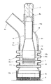
図1に示した実施形態は、ガン本体8と筒状ブラシ16との間に可撓性の筒体15を設けた点が、図4に示した従来の構成と大きく相違する点である。その他の構成は従来と同じなので、従来と同一の構成要素については、従来と同一符号を用いて説明する。
この実施形態においても、ノズル3をブラストホース2に接続して、加圧タンク1のブラスト材をノズル3に導くようにしている。
The embodiment shown in FIG. 1 is greatly different from the conventional configuration shown in FIG. 4 in that a
Also in this embodiment, the
また、ガン本体8の吸引筒部8cをバキュームホース5に接続し、この吸引筒部8cから吸い込んだブラスト材、粉塵あるいは塗膜片等を回収タンク6に導いている。この回収タンク6では、ブラスト材と、粉塵あるいは塗膜片等とを分別し、ブラスト材を加圧タンク1に再生させる一方、粉塵あるいは塗膜片等をダストコレクター7で捕集するようにしている。
Further, the
そして、上記ノズル3は、耐摩耗性の合成ゴムからなるガン本体8の一方の筒部8aにぴったりとはめている。この上記ガン本体8は、上記一方の筒部8aとは反対側に他方の筒部8bを設けるとともに、この他方の筒部8bの内径を、上記一方の筒部8aの内径よりも大きくしている。そして、一方の筒部8aと他方の筒部8bとのほぼ境界部分に吸引筒部8cを形成し、この吸引筒部8cを上記バキュームホース5に接続している。これらの構成は従来と同じである。
The
また、ノズル3から噴出したブラスト材を広角に噴出させるディフューザー14は、ガン本体8の一方の筒部8aにぴったりはまる外径を有する小径部14aと、この小径部14aよりも外径を大きくした大径部14bとを備えている。
さらに、上記小径部14aをガン本体8の一方の筒部8aに挿入して、当該筒部8aの先端をノズル3につき合わせている。
Further, the
Further, the
また、ディフューザー14の大径部14bは、上記ガン本体8の他方の筒部8b側における開口部8dから突出して設けられる。そして、ディフューザー14とガン本体8の他方の筒部8bとの間には、隙間が形成され、この隙間を吸引用通路10としている。
Further, the large-
上記のようにしたディフューザー14は、その大径部14bの開口側の内周面に、周方向に連続する凸部14cを、ディフューザー14の軸線方向すなわちノズル3の噴出方向に複数段設けている。
そして、この凸部14cは、周方向に切れ目なく連続する一条の凸部14cを軸線方向に複数段設けるとともに、各凸部14cは互いに平行にしている。
なお、このディフューザー14は、金属製にすることによって反発性を高め、ディフューザー14の内周面に衝突したブラスト材の流れの勢いが吸収されないようにしている。
The
And this
The
また、上記ガン本体8と後述する筒状ブラシ16との間には、可撓性の筒体15が着脱可能に設けられている。この筒体15は、上記ガン本体8と連結するガン本体連結部15aと、上記筒状ブラシ16と連結するブラシ連結部15bと、このガン本体連結部15aと上記ブラシ連結部15bとの間に設けられた可撓部15cとから構成される。
そして、上記筒体15のガン本体連結部15aは、上記ガン本体8の他方の筒部8b側における開口部8dの外側にはめ込まれ、その上からリング状の締付け金具17によって締付けられている。
A
The gun
そして、上記ガン本体8から突出して設けられたディフューザー14は、筒体15の内部に挿入され、このディフューザー14の周囲と筒体15の内周との間には所定の間隔が保たれる。
この筒体15は、柔らかいゴム等の材質からなるため可撓性を備えるとともに、全方向に撓むようになっている。また、この筒体15は、上記可撓部15cの外側に複数の環状凸部Tが形成され、全体として蛇腹状にしている。この環状凸部Tは、周方向に一条の凸部が切れ目なく連続するとともに、それら凸部を軸方向に複数間隔を保って連続する形態になっている。
The
Since this
この環状凸部Tは、リブの役割を担うので、負圧に対して周方向の形状を維持することができる。したがって、上記筒体15内に強い吸引力が働いても、この吸引力によって上記可撓部15cが内側に撓んでしまい、上記吸引用通路10を塞いでしまうようなことがない。このように、上記吸引用通路10が維持されるので、ブラスト材や塗膜片等を円滑に回収できる。
なお、この環状凸部Tは、周方向に一条の凸部が切れ目なく連続するとともに、それら凸部を軸方向に複数間隔を保って連続する形態になっているが、筒体15の周方向の形状が維持されればよいので、凸部が螺旋状に連続する形態であってもよい。
Since this annular convex part T plays the role of a rib, it can maintain the shape of the circumferential direction with respect to negative pressure. Therefore, even if a strong suction force is applied to the
In addition, while this annular convex part T has the form where a single convex part continues in the circumferential direction without a break, and these convex parts are continuously maintained at a plurality of intervals in the axial direction, the circumferential direction of the
他方、上記ガン本体連結部15aと反対側のブラシ連結部15bの外周には、上記筒状ブラシ16が取り外し可能にはめつけられている。この筒状ブラシ16の先端開口は、図1のように筒状ブラシ16の軸線に直交する面を備えるとともに、上記筒体15の外周に沿うように毛が設けられている。
On the other hand, the
この筒状ブラシ16は、ブラスト材や、粉塵あるいは塗膜片の飛散防止用として機能するとともに、吸引筒部8cからブラスト材を吸引するときのエア吸入口としての機能を果たしている。このように機能させるため、上記筒状ブラシ16の毛は、高強度で硬いものが使用される。
The
さらに、上記可撓部15cの上記環状凸部T間には、必要に応じて、金属やゴム等からなるリング状のスペーサ18がはめられている。
このように、上記環状凸部T間にリング状のスペーサ18がはめられることによって、上記可撓部15cの軸方向の収縮が制限されるので、上記ボルト等とディフューザーが干渉しあってディフューザー14の首ふり運動を妨げることはない。
Furthermore, a ring-shaped
Since the ring-shaped
このような構成において、この実施形態は、上記筒体15の可撓部15cを全方向に撓ませることによって、上記ボルト等の軸線に対してディフューザー14を全方向に向かわせることができる。つまり、ノズル3やディフューザー14に、簡単に首ふり運動をさせることができる。
In this configuration, in this embodiment, the
次に、この実施形態の作業方法について説明をする。
この実施形態の研磨目的となるボルト等は、橋梁などの既存の建造物4に締結されているものである。
先ず、作業者は、上記ボルト等を筒状ブラシ16で囲うように上記ガン本体8を配置する。このとき、この筒状ブラシ16の先端開口は、上記ボルト等が締結された建造物4に隙間なく圧接される。
Next, the working method of this embodiment will be described.
The bolts and the like that are the purpose of polishing in this embodiment are fastened to an existing building 4 such as a bridge.
First, the operator arranges the
そして、作業者は、上記可撓部15cを撓ませながら、上記ガン本体8を上記建造物4側に押し付けて、ディフューザー14の開口を上記ボルト等に近づける。このようにディフューザー14を上記ボルト等に近づけるのは、筒体15内では吸引力と噴出力とが同時に働くので、この2つの流れを分けるためである。つまり、吸引力でブラスト材の勢いが減衰されないように、ディフューザー14が壁となってブラスト材の流れをガイドしている。したがって、ディフューザー14の開口を上記ボルト等に近づければ近づけるほど、ブラスト材の勢いが強いまま上記ボルト等に上記ブラスト材を衝突させることができる。
Then, the operator presses the
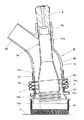
図1及び図2は、ディフューザー14の開口径と同程度の大きさの上記ボルト等を研磨するため、上記環状凸部T間にリング状のスペーサ18を設けた状態を示している。なお、図の二点鎖線は、研磨目的の上記ボルト等を示している。
このスペーサ18は、上記ボルト等にディフューザー14を近づけて傾けたときに、上記ディフューザー14の先端が上記ボルト等に当たることを防止している。ディフューザー14が上記ボルト等に当たってしまうと、全面の研磨作業ができなくなってしまう。そこで、上記スペーサ18は、上記ボルト等とディフューザー14との距離を、ディフューザー14の全方向に傾ける動きを妨げない距離に保っている。
FIGS. 1 and 2 show a state in which a ring-shaped
The
このように、このスペーサ18は、上記可撓部15cの軸方向の収縮を制限させ、上記ボルト等とディフューザー14との距離を保つので、ディフューザー14と干渉しない。さらに、上記ボルト等とディフューザー14との距離を、ディフューザー14の全方向に傾ける動きを妨げない最小の間隔に保つことによって、ブラスト材の流れの勢いが強いまま、上記ボルト等の側面にブラスト材を当てられる。
Thus, the
また、上記スペーサ18は、上記ボルト等の形状や取付け状況が変わる場合に、このスペーサ18を状況に応じて着脱させることで、上記ボルト等とディフューザー14との距離を調整できる。例えば、ディフューザー14の内径よりも小さな上記ボルト等の場合は、スペーサ18を取り外して、ディフューザー14を上記ボルト等に近づけて作業を行う。このように、多様な現場の状況に対応できるので、汎用性が高くなる。
The
続いて、作業者は、図示しないスイッチをオンにして、上記ノズル3からブラスト材を噴出させ、上記ボルト等及び建造物4に上記ブラスト材を衝突させる。そして、図2に示すように、上記筒状ブラシ16を上記建造物4に圧接させたまま、上記可撓部15cを撓ませ、上記ガン本体8のディフューザー14の向きを上記ボルト等の全面に向くように動かす。
Subsequently, the operator turns on a switch (not shown), ejects the blast material from the
このような首ふり運動によって、上記ボルト等の側面には、ディフューザー14の凸部14cで跳ね返されたブラスト材が衝突する。また、作業者の操作によって、ノズル3の軸中心線に沿って直進するブラスト材が、上記ボルト等の全面に直接衝突する。この衝突する衝撃力で、上記ボルト等の錆や塗膜片等を削り取る。
Due to such a neck motion, the blast material bounced back by the
上記ボルト等は、少しでも磨き残しがあると、その磨き残した錆の部分から腐食が進んでしまう。そのため、上記ボルト等の全面は、もれなく研磨される。
そして、上記ボルト等や建造物4に当たって勢いを失ったブラスト材は、粉塵や研削された塗膜片等とともに、ディフューザー14と筒体15との間を通過し、吸引用通路10、吸引筒部8c及びバキュームホース5を通って回収タンク6に集められる。
If the bolts or the like are left unpolished, corrosion proceeds from the unpolished rust. Therefore, the entire surface of the bolt or the like is polished without any leakage.
The blasting material that has lost its momentum by hitting the bolts or the building 4 passes between the
この実施形態によれば、このようにノズル3及びディフューザー14の向きを全方向に向けられるので、例えば、ブラスト材を、入射角を保って上記ボルト等や建造物4の表面等に吹き付けることができる。しかも、上記入射角を保って、ノズル3やディフューザー14に首ふり運動をさせることができる。
上記のように上記ボルト等や建造物4の表面等に対して、ブラスト材を、入射角を保って吹き付けられるので、衝突したブラスト材は、その入射角に対応した反射角を保って跳ね返される。
According to this embodiment, since the direction of the
As described above, the blast material is blown against the bolt or the surface of the building 4 while maintaining the incident angle, so that the blasted material that has collided is bounced back while maintaining the reflection angle corresponding to the incident angle. .
このように入射角に対応した反射角を保ってブラスト材が跳ね返されるので、このブラスト材の多くを、十分な勢いを保ちながらディフューザー14の内周面に直接向かわせることができる。
そして、ディフューザー14の凸部14cに勢いよく衝突する。このようにして凸部14cに衝突したブラスト材は、再び跳ね返されて上記ボルト等の側面等に衝突して、その側面を研磨することになる。
As described above, since the blast material is rebounded while maintaining the reflection angle corresponding to the incident angle, most of the blast material can be directed directly to the inner peripheral surface of the
And it collides with the
特に、ブラスト材が当たる凸部14cの面の角度を調整することによって、凸部14cに当たって反射されるブラスト材の反射角を制御でき、上記ボルト等の側面に対して、ブラスト材を効率よく吹き付けることができる。
また、ノズル3及びディフューザー14の軸中心線を上記ボルト等や建造物4の表面に対して直角に保って、ブラスト材を噴出させることもできる。
In particular, by adjusting the angle of the surface of the
Further, the blast material can be ejected while keeping the axial center lines of the
さらに、筒体15に可撓部15cを設けたので、筒状ブラシ16と建造物4の表面との間に隙間を作ることなく、ノズル3やディフューザー14の軸中心線を、簡単に全方向に向けることができる。つまり、ノズル3やディフューザー14に首ふり運動をさせても、筒状ブラシ16と建造物4の表面との間に隙間ができたりしない。
Further, since the
このように、本願発明は、上記ボルト等の側面にも十分な量のブラスト材を勢いよく衝突させることができるので、その研磨作業の時間を短縮することができる。
具体的には、従来の研磨時間の半分以下で研磨できるようになった。そのため、工期等も半分に短縮できる。
As described above, according to the present invention, a sufficient amount of the blasting material can be vigorously collided with the side surfaces of the bolts and the like, so that the polishing operation time can be shortened.
Specifically, it has become possible to polish in less than half the conventional polishing time. Therefore, the construction period can be shortened to half.
また、ノズル3やディフューザー14に首ふり運動をさせても、筒状ブラシ16と建造物4の表面との間に隙間ができたりしないので、従来のようにブラスト材や塗膜片が周囲に飛散することもなくなる。
このように、上記塗膜片等を周囲に飛散させないので、環境汚染や作業者などの健康被害を引き起こすことが軽減される。
Further, even if the
As described above, since the coating film pieces and the like are not scattered to the surroundings, it is possible to reduce environmental pollution and health hazards to workers.
なお、このディフューザー14は、その大径部14bの開口側の内周面に、周方向に連続する凸部14cを、ノズル3の噴出方向に複数段を設けているが、大径口14bの内周面に凸部14cなどの特別な加工を施していないディフューザーを利用できるのは当然である。
The
既設の建造物に締結されたボルトやナット、リベット等の錆や塗膜を研磨する研磨作業に最適である。 It is ideal for polishing work that polishes rust and paint film such as bolts, nuts and rivets fastened to existing buildings.
3…ノズル、4…建造物、8…ガン本体、9,14…ディフューザー、10…吸引用通路、11,16…筒状ブラシ、15…筒体、15c…可撓部、17…締付け金具、18…スペーサ、T…環状凸部
DESCRIPTION OF
第1の発明は、上記ガン本体と上記筒状ブラシとが筒体を介して着脱可能に設けられている。この筒体は、上記ガン本体と連結するガン本体連結部と、上記筒状ブラシと連結するブラシ連結部と、このガン本体連結部と上記ブラシ連結部との間に設けられた可撓性の可撓部とで構成されている。 In the first invention, the gun body and the cylindrical brush are detachably provided via a cylinder. The cylindrical body includes a gun body connecting portion that is connected to the gun body, a brush connecting portion that is connected to the cylindrical brush, and a flexible body provided between the gun body connecting portion and the brush connecting portion. It is comprised with the flexible part .
また、上記可撓部には複数の環状凸部が形成されるとともに、全体的に蛇腹状にされている。さらに、上記可撓部の外側の上記環状凸部間にリング状のスペーサが着脱自在に装着されている。そして、上記可撓部を撓ませながら上記ガン本体とともにディフューザーの向きを全方向に向けられた点に特徴を有する。In addition, the flexible portion is formed with a plurality of annular convex portions, and has a bellows shape as a whole. Further, a ring-shaped spacer is detachably mounted between the annular convex portions outside the flexible portion. And it has the characteristics in that the direction of the diffuser is directed in all directions together with the gun body while bending the flexible part.
なお、環状凸部の形態には、周方向に一条の凸部が切れ目なく連続するとともに、それら凸部を軸方向に複数間隔を保って連続する形態、あるいは一条の凸部が間隔を保って螺旋状に連続する形態のいずれも含まれる。In the form of the annular convex portion, a single convex portion is continuous in the circumferential direction, and the convex portions are continuous with a plurality of intervals in the axial direction, or the single convex portion is spaced. Any of the spiral continuous forms is included.
このようにノズル及びディフューザーの向きを全方向に向けられるので、例えば、ブラスト材を、入射角を保ってボルト等や建造物の表面等に吹き付けることができる。しかも、上記入射角を保って、ノズルやディフューザーに首ふり運動をさせることができる。Thus, since the direction of the nozzle and the diffuser can be directed in all directions, for example, the blast material can be sprayed onto a bolt or the like, the surface of a building, or the like while maintaining the incident angle. In addition, the nozzle and the diffuser can be swung with the incident angle maintained.
上記のようにボルト等や建造物の表面等に対して、ブラスト材を、入射角を保って吹き付けられるので、衝突したブラスト材は、その入射角に対応した反射角を保って跳ね返される。 As described above, the blast material is blown against the bolts or the surface of the building while maintaining the incident angle, so that the collided blast material is bounced back while maintaining the reflection angle corresponding to the incident angle.
このように入射角に対応した反射角を保ってブラスト材が跳ね返されるので、このブラスト材の多くを、十分な勢いを保ちながらディフューザーの内周面に直接向かわせることができる。Since the blast material is rebounded while maintaining the reflection angle corresponding to the incident angle in this way, most of the blast material can be directed directly to the inner peripheral surface of the diffuser while maintaining sufficient momentum.
また、ノズル及びディフューザーの軸中心線をボルトやナット、建造物の表面に対して直角に保って、ブラスト材を噴出させることもできる。Further, the blast material can be ejected while keeping the axial center line of the nozzle and the diffuser at right angles to the surface of the bolt, nut or building.
さらに、筒体に可撓部を設けたので、筒状ブラシと建造物の表面との間に隙間を作ることなく、ノズルやディフューザーの軸中心線を、簡単に全方向に向けることができる。つまり、ノズルやディフューザーに首ふり運動をさせても、筒状ブラシと建造物の表面との間に隙間ができたりしない。Furthermore, since the flexible part is provided in the cylindrical body, the axial center line of the nozzle and the diffuser can be easily directed in all directions without creating a gap between the cylindrical brush and the surface of the building. That is, even if the nozzle or diffuser is swung, no gap is formed between the cylindrical brush and the surface of the building.
第2の発明は、上記ディフューザーの開口側の内周面に、周方向に連続する凸部が、ディフューザーの軸線方向に複数段設けられた点に特徴を有する。The second invention is characterized in that a plurality of convex portions continuous in the circumferential direction are provided on the inner peripheral surface on the opening side of the diffuser in the axial direction of the diffuser.
上記のように入射角を保って吹き付けられたブラスト材は、ボルトやナット、建造物の表面等で跳ね返されるとともに、ディフューザーの凸部に勢いよく衝突する。The blast material sprayed while maintaining the incident angle as described above is bounced back by bolts, nuts, the surface of the building, and the like, and collides with the convex portion of the diffuser vigorously.
このようにして凸部に衝突したブラスト材は、再び跳ね返されてボルト等の側面等に衝突して、その側面を研磨することになる。The blast material colliding with the convex portion in this way is rebounded again and collides with a side surface such as a bolt and the side surface is polished.
また、上記可撓部には複数の環状凸部が形成されるとともに、全体的に蛇腹状にされているので、ノズルやディフューザーに、簡単に首ふり運動をさせることができる。In addition, the flexible portion is formed with a plurality of annular projections and is generally bellows-like, so that the nozzle and the diffuser can be easily swung.
さらに、環状凸部は、リブの役割を担うので、上記可撓部の周方向の形状が維持される。したがって、仮に上記可撓部に強い吸引力が働いても吸引用通路が確保されるので、ブラスト材や塗膜片等が円滑に回収される。 Furthermore, since the annular convex portion serves as a rib, the shape of the flexible portion in the circumferential direction is maintained. Therefore, even if a strong suction force is applied to the flexible portion, the suction passage is secured, so that the blast material, the coating film piece, and the like are collected smoothly.
特に、この研磨ガン装置の吸引用通路には、吸引時に負圧が生じる。上記可撓部は、可撓性がある材質からなるため、上記負圧に負けて上記可撓部の形状が維持できない場合が生じる。このように上記可撓部の形状が維持できないと、上記吸引用通路が閉ざされ、ブラスト材や塗膜片等が適切に回収できなくなる。しかし、この第1の発明は、上記可撓部の周方向の形状が維持されるので、上記吸引用通路が確保される。In particular, a negative pressure is generated in the suction passage of the polishing gun device during suction. Since the flexible portion is made of a flexible material, the flexible portion may be unable to maintain its shape under the negative pressure. If the shape of the flexible portion cannot be maintained in this manner, the suction passage is closed, and the blast material, the coating film pieces, and the like cannot be properly collected. However, in the first invention, the shape of the flexible portion in the circumferential direction is maintained, so that the suction passage is ensured.
そして、このスペーサは、上記可撓部の軸方向の収縮を制限させ、上記ボルト等とディフューザーとの間の適切な距離を保てるので、ボルト等とディフューザーが干渉しあってディフューザーの首ふり運動を妨げることはない。This spacer limits the contraction of the flexible portion in the axial direction and can maintain an appropriate distance between the bolt and the diffuser, so that the bolt and the diffuser interfere with each other to cause the neck of the diffuser to swing. There is no hindrance.
第2の発明によれば、ボルトやナット、建造物の表面等に跳ね返されたブラスト材が、凸部に当たって再び跳ね返されて、ボルト等の側面を研磨することができる。特に、ブラスト材が当たる凸部の面の角度を調整することによって、凸部に当たって反射されるブラスト材の反射角を制御でき、ボルト等の側面に対して、ブラスト材を効率よく吹き付けることができる。According to the second invention, the blast material bounced back to the surface of the bolt or nut, the building, or the like is rebounded by hitting the convex portion, and the side surface of the bolt or the like can be polished. In particular, by adjusting the angle of the surface of the convex portion that the blast material hits, the reflection angle of the blast material reflected by the convex portion can be controlled, and the blast material can be efficiently sprayed on the side surface of the bolt or the like. .
Claims (4)
このノズルに連続するディフューザーと、
このディフューザーの外側に設けたガン本体と、
このガン本体とディフューザーとの間に設けられた吸引用通路と、
上記ノズルから噴出された上記ブラスト材が導かれる筒状ブラシと
が備えられた研磨ガン装置であって、
上記ガン本体と上記筒状ブラシとが筒体を介して着脱可能に設けられ、
この筒体は、上記ガン本体と連結するガン本体連結部と、
上記筒状ブラシと連結するブラシ連結部と、
このガン本体連結部と上記ブラシ連結部との間に設けられた可撓性の可撓部とからなり、
上記可撓部を撓ませながら上記ガン本体とともに、ノズル及びディフューザーの向きを全方向に向けられる構成にした研磨ガン装置。 A nozzle for ejecting blast material;
A diffuser continuous with this nozzle,
The gun body on the outside of the diffuser,
A suction passage provided between the gun body and the diffuser;
A polishing gun apparatus provided with a cylindrical brush to which the blast material ejected from the nozzle is guided,
The gun body and the cylindrical brush are detachably provided via a cylinder,
The cylindrical body includes a gun body connecting portion that is connected to the gun body,
A brush coupling portion coupled to the cylindrical brush;
It consists of a flexible flexible part provided between the gun body connecting part and the brush connecting part,
A polishing gun apparatus configured such that the direction of the nozzle and the diffuser is directed in all directions together with the gun body while bending the flexible portion.
The polishing gun apparatus according to claim 3, wherein a ring-shaped spacer is detachably mounted between the annular convex portions of the flexible portion.
Priority Applications (1)
| Application Number | Priority Date | Filing Date | Title |
|---|---|---|---|
| JP2016177760A JP6284106B1 (en) | 2016-09-12 | 2016-09-12 | Polishing gun device |
Applications Claiming Priority (1)
| Application Number | Priority Date | Filing Date | Title |
|---|---|---|---|
| JP2016177760A JP6284106B1 (en) | 2016-09-12 | 2016-09-12 | Polishing gun device |
Publications (2)
| Publication Number | Publication Date |
|---|---|
| JP6284106B1 JP6284106B1 (en) | 2018-02-28 |
| JP2018043302A true JP2018043302A (en) | 2018-03-22 |
Family
ID=61282637
Family Applications (1)
| Application Number | Title | Priority Date | Filing Date |
|---|---|---|---|
| JP2016177760A Active JP6284106B1 (en) | 2016-09-12 | 2016-09-12 | Polishing gun device |
Country Status (1)
| Country | Link |
|---|---|
| JP (1) | JP6284106B1 (en) |
Families Citing this family (1)
| Publication number | Priority date | Publication date | Assignee | Title |
|---|---|---|---|---|
| CN113714938B (en) * | 2021-09-01 | 2022-11-29 | 郑州大学 | Protection device suitable for modified equipment of mixed efflux of triaxial linkage |
Family Cites Families (9)
| Publication number | Priority date | Publication date | Assignee | Title |
|---|---|---|---|---|
| US2846822A (en) * | 1955-11-07 | 1958-08-12 | Walter F Brack | Sand blast machine |
| JPH01155165U (en) * | 1988-04-18 | 1989-10-25 | ||
| JPH0613839Y2 (en) * | 1988-07-22 | 1994-04-13 | 新東工業株式会社 | Cleaning equipment for fixed cylindrical products |
| JPH07649U (en) * | 1993-06-14 | 1995-01-06 | 関電興業株式会社 | Attachment for vacuum blast |
| US5667430A (en) * | 1995-08-25 | 1997-09-16 | Ltc Americas Inc. | Bolt head blaster |
| US5709590A (en) * | 1995-10-13 | 1998-01-20 | Ltc Americas Inc. | Pressure-balanced vacuum blast head |
| JP3031304U (en) * | 1996-05-16 | 1996-11-22 | 株式会社タダキカイ | Dust scattering prevention device for sandblasting |
| JPH11207624A (en) * | 1998-01-22 | 1999-08-03 | Fuji Seisakusho:Kk | Cleaning system for structure surface |
| JP2014136271A (en) * | 2013-01-16 | 2014-07-28 | Maru-T Ohtsuka Corp | Polishing gun device |
-
2016
- 2016-09-12 JP JP2016177760A patent/JP6284106B1/en active Active
Also Published As
| Publication number | Publication date |
|---|---|
| JP6284106B1 (en) | 2018-02-28 |
Similar Documents
| Publication | Publication Date | Title |
|---|---|---|
| US11491516B2 (en) | Vacuum spray apparatus and uses thereof | |
| US10189034B2 (en) | Nozzle system and method | |
| US5248095A (en) | Rotating nozzle | |
| US6626738B1 (en) | Performance fan nozzle | |
| AU2010325762B2 (en) | Abrasive blasting | |
| JP6284106B1 (en) | Polishing gun device | |
| JP2014136271A (en) | Polishing gun device | |
| JP4522354B2 (en) | Blow clean device | |
| CN108177093A (en) | For carrying out the mechanism of blasting treatment to endoporus | |
| JP2011255293A (en) | Air gun with function of suction recovery and blowing, and cleaning method using the same | |
| CN110682215B (en) | High-pressure rust removal spray head | |
| KR101669999B1 (en) | Spray gun of airless with inhale module for inhaling paint | |
| JP2008114211A (en) | Fluid ejection device | |
| CN204486064U (en) | A kind of suppressing dust with dry mist shower nozzle | |
| KR101069799B1 (en) | nozzle | |
| JP6441113B2 (en) | Cleaning system nozzle head and cleaning system | |
| JPH0742605Y2 (en) | Blast nozzle | |
| US20170028423A1 (en) | Shield apparatus for a blowgun | |
| JP4242444B1 (en) | Square piping cleaning nozzle and piping cleaning device | |
| JPS63144962A (en) | Two throw nozzle for sand blast | |
| JP2007144261A (en) | Cleaning apparatus and method | |
| AU2009246735B2 (en) | Build-up minimizing spray gun tip | |
| JP2005111628A (en) | Shot blasting apparatus | |
| CN105382706A (en) | Pneumatic sand blasting machine | |
| CN104875126A (en) | Handheld pneumatic sand-blasting gun |
Legal Events
| Date | Code | Title | Description |
|---|---|---|---|
| TRDD | Decision of grant or rejection written | ||
| A01 | Written decision to grant a patent or to grant a registration (utility model) |
Free format text: JAPANESE INTERMEDIATE CODE: A01 Effective date: 20180109 |
|
| A61 | First payment of annual fees (during grant procedure) |
Free format text: JAPANESE INTERMEDIATE CODE: A61 Effective date: 20180122 |
|
| R150 | Certificate of patent or registration of utility model |
Ref document number: 6284106 Country of ref document: JP Free format text: JAPANESE INTERMEDIATE CODE: R150 |
|
| R250 | Receipt of annual fees |
Free format text: JAPANESE INTERMEDIATE CODE: R250 |
|
| R250 | Receipt of annual fees |
Free format text: JAPANESE INTERMEDIATE CODE: R250 |
|
| RD03 | Notification of appointment of power of attorney |
Free format text: JAPANESE INTERMEDIATE CODE: R3D03 |
|
| R250 | Receipt of annual fees |
Free format text: JAPANESE INTERMEDIATE CODE: R250 |