JP2018043256A - Laser machining device - Google Patents
Laser machining device Download PDFInfo
- Publication number
- JP2018043256A JP2018043256A JP2016178350A JP2016178350A JP2018043256A JP 2018043256 A JP2018043256 A JP 2018043256A JP 2016178350 A JP2016178350 A JP 2016178350A JP 2016178350 A JP2016178350 A JP 2016178350A JP 2018043256 A JP2018043256 A JP 2018043256A
- Authority
- JP
- Japan
- Prior art keywords
- laser
- laser beam
- incident
- optical path
- optical paths
- Prior art date
- Legal status (The legal status is an assumption and is not a legal conclusion. Google has not performed a legal analysis and makes no representation as to the accuracy of the status listed.)
- Pending
Links
Images


Landscapes
- Laser Beam Processing (AREA)
Abstract
Description
本発明は、レーザ加工装置に関し、特にレーザビームをプロセスファイバにより導光するレーザ加工装置に関する。 The present invention relates to a laser processing apparatus, and more particularly to a laser processing apparatus that guides a laser beam through a process fiber.
レーザ発振器により発振されるレーザ光は、単色性および指向性に優れており、かつ、コヒーレントな光であるため、切断、穴あけ、溶接、表面処理、マーキング等の様々な工業的な加工に用いられている。 Laser light oscillated by a laser oscillator is excellent in monochromaticity and directivity, and is coherent, so it is used for various industrial processes such as cutting, drilling, welding, surface treatment, and marking. ing.
従来のレーザ加工装置について、図6を参照しながら説明する。図6は、レーザ加工装置の構成を模式的に示す斜視図である。図中、同様の構成および機能を備える部材には、同じ符号を付している。 A conventional laser processing apparatus will be described with reference to FIG. FIG. 6 is a perspective view schematically showing the configuration of the laser processing apparatus. In the figure, members having the same configuration and function are denoted by the same reference numerals.
レーザ加工装置2000は、レーザ発振器2100と、レーザ発振器2100から出射されるレーザビームLB100の光路を切り替えるビーム光路切替部2200と、レーザビームLB100が入射する複数のプロセスファイバ2300(2300a〜2300c)と、を備える。ビーム光路切替部2200の内部は例えば大気雰囲気であり、ビーム光路切替部2200内では、レーザビームLB100は大気を媒体にして伝搬される。ビーム光路切替部2200にはプロセスファイバ2300の一方の端部が接続しており、レーザビームLB100は、ビーム光路切替部2200を経て、プロセスファイバ2300に入射する。プロセスファイバ2300は、レーザビームLB100を、ビーム光路切替部2200から加工対象物(ワークW)近傍にまで伝搬するための媒体である。
The
通常、1台のレーザ発振器2100には、複数の加工ヘッド2400(図示例では、3台)が接続している。ビーム光路切替部2200は、レーザビームLB100の光路を切り替えて、レーザビームLB100を複数のプロセスファイバ2300(2300a〜2300c)のうちのいずれかに導光する。プロセスファイバ2300の内部に導光されたレーザビームLB100は、やがて、プロセスファイバ2300の他方の端部に接続された加工ヘッド2400に到達する。このように、レーザビームLB100が導光される加工ヘッド2400をビーム光路切替部2200により切り替えて、タイムシェアリングを行いながら、複数のワークWに対してレーザ加工が施される。通常、各プロセスファイバ2300のコア径、および、ビーム光路切替部2200から各加工ヘッド2400の先端までの光学的な条件(例えば、屈折率)はそれぞれ等しいため、複数のワークWに対して、同じ条件でレーザ加工が施される。以下、加工ヘッド2400からワークWに照射されるレーザビームLBをLB400と称する。
Usually, a plurality of processing heads 2400 (three in the illustrated example) are connected to one
ビーム光路の切り替えに関して、特許文献1は、プリズムのような偏光手段によってレーザビームの光路を変化させる方法を教示している。また、特許文献2は、プロセスファイバの配置を変化させて、異なるプロセスファイバにレーザビームを入射させる方法を提案している。
Regarding switching of the beam optical path,
加工ヘッド2400は、コリメータレンズ2410および集光レンズ2420を備える。加工ヘッド2400に到達したレーザビームLB400は、集光レンズ2420によって密度が高められて、ワークWに照射される。ワークWは、加工テーブル2500上に固定されている。一方、加工ヘッド2400は、X軸モータ2710およびY軸モータ2720によって移動可能であり、加工ヘッド2400をワークWに対して相対的に移動させながら、所定の加工が施される。レーザ発振器2100、X軸モータ2710およびY軸モータ2720は、加工制御部2600により制御されており、その状態は、加工制御部2600に同期されている。
The
ワークWを高精度で効率よく加工するには、ワークWに照射されるレーザビームLB400のBPP(Beam Parameter Product)がポイントとなる。
BPPは、レーザビームLBの品質を表現するのに、一般的に用いられるパラメータである。BPPは、ビームの拡がりの半角度θ(ミリラジアン、mrad)と、焦点(ビームウエスト)におけるビーム半径w(ミリメートル、mm)との積で求められる。BPPが小さいレーザビームLBは、より小さいビーム径であって、焦点深度が短くなるように集光され得る。一方、BPPの大きいレーザビームLBは、大きなビーム径であって、焦点深度が長くなるように集光され得る。そのため、例えば、薄いワークWを切断する場合には、BPPの小さなレーザビームLBが適しており、厚いワークWを切断する場合には、BPPの大きなレーザビームLBが適している。つまり、BPPは、加工精度および生産性を向上させるために重要なパラメータの一つである。なお、焦点深度とは、ビーム径が光学的に同じであると見なされる範囲であって、具体的には、ビーム半径の2√2倍の径に拡がるまでの範囲(レイリーの範囲)である。
In order to efficiently process the workpiece W with high accuracy, BPP (Beam Parameter Product) of the laser beam LB 400 irradiated onto the workpiece W is a point.
BPP is a parameter generally used for expressing the quality of the laser beam LB. BPP is determined by the product of the beam half-angle θ (milliradian, mrad) and the beam radius w (millimeter, mm) at the focal point (beam waist). The laser beam LB having a small BPP can be condensed so as to have a smaller beam diameter and a short focal depth. On the other hand, the laser beam LB having a large BPP has a large beam diameter and can be condensed so that the depth of focus becomes long. Therefore, for example, a laser beam LB with a small BPP is suitable for cutting a thin workpiece W, and a laser beam LB with a large BPP is suitable for cutting a thick workpiece W. That is, BPP is one of the important parameters for improving processing accuracy and productivity. The depth of focus is a range in which the beam diameters are considered to be optically the same, and specifically, a range (Rayleigh range) until the beam diameter expands to 2√2 times the beam radius. .
しかし、従来のレーザ加工装置では、ワークWあるいは加工条件に応じてレーザビームLB400のBPPを変えることはできず、加工精度および生産性が低下し易い。 However, in the conventional laser processing apparatus, the BPP of the laser beam LB 400 cannot be changed according to the workpiece W or processing conditions, and the processing accuracy and productivity are likely to decrease.
本発明の一局面は、レーザ発振器と、前記レーザ発振器から出射されるレーザビームが通る複数の光路と、前記レーザ発振器から出射される前記レーザビームを、前記複数の光路から選択される1つに導光するビーム光路切替部と、前記複数の光路にそれぞれ配置される複数のプロセスファイバと、前記複数のプロセスファイバのそれぞれに対応するように前記複数の光路に配置されており、前記レーザビームを集光して、対応する前記プロセスファイバに導光する複数の集光レンズと、を備え、前記複数の集光レンズが、互いに異なる焦点距離を有し、前記複数のプロセスファイバがそれぞれ、対応する前記集光レンズの前記焦点距離に応じたコア径を有する、レーザ加工装置である。 According to one aspect of the present invention, a laser oscillator, a plurality of optical paths through which a laser beam emitted from the laser oscillator passes, and the laser beam emitted from the laser oscillator are selected from the plurality of optical paths. A beam optical path switching unit for guiding light, a plurality of process fibers respectively disposed in the plurality of optical paths, and disposed in the plurality of optical paths so as to correspond to each of the plurality of process fibers; A plurality of condensing lenses for condensing and guiding the corresponding process fibers, the plurality of condensing lenses having different focal lengths, and the plurality of process fibers respectively corresponding It is a laser processing apparatus which has a core diameter according to the focal length of the condensing lens.
本発明の他の一局面は、レーザ発振器と、前記レーザ発振器から出射されるレーザビームが通る複数の光路と、前記レーザ発振器から出射される前記レーザビームを、前記複数の光路から選択される1つに導光するビーム光路切替部と、前記複数の光路に配置される複数のプロセスファイバと、前記複数のプロセスファイバのそれぞれに対応するように前記複数の光路に配置されており、前記レーザビームを集光して、対応する前記プロセスファイバに導光する複数の集光レンズと、を備え、前記複数の集光レンズの焦点位置から、それぞれ対応する前記複数のプロセスファイバの前記レーザビームが入射する入射端までの入射距離が、互いに異なっており、前記複数のプロセスファイバがそれぞれ、対応する前記焦点位置からの前記入射距離に応じたコア径を有する、レーザ加工装置である。 According to another aspect of the present invention, a laser oscillator, a plurality of optical paths through which a laser beam emitted from the laser oscillator passes, and the laser beam emitted from the laser oscillator are selected from the plurality of optical paths. A beam optical path switching unit that guides light to the plurality of optical fibers, a plurality of process fibers disposed in the plurality of optical paths, and a plurality of process fibers disposed to correspond to the plurality of process fibers, and the laser beam A plurality of condensing lenses that condense the light and guide it to the corresponding process fiber, and the laser beams of the plurality of corresponding process fibers respectively enter from the focal positions of the plurality of condensing lenses. The incident distances to the incident ends are different from each other, and each of the plurality of process fibers has a corresponding incident distance from the corresponding focal position. Having a core diameter corresponding to a laser processing apparatus.
本発明のレーザ加工装置によれば、様々なワークに応じた最適なBPPを有するレーザビームを照射することができるため、加工精度および生産性に優れるレーザ加工が可能となる。 According to the laser processing apparatus of the present invention, since it is possible to irradiate a laser beam having an optimum BPP corresponding to various workpieces, laser processing with excellent processing accuracy and productivity becomes possible.
図7に、3種類のレーザビームLBを用いてワーク(ステンレス鋼板)を切断加工する場合の、厚みと切断速度との関係を表すグラフを示す。レーザビームLBは、いずれも出力4kWのレーザ発振器から出射され、そのBPPは、それぞれ4mm・mrad、6mm・mradおよび8mm・mradである。このグラフからわかるように、切断速度は、レーザビームLBのBPPおよびワークの厚みに影響される。例えば、ワークの厚みが5mm未満である場合、4mm・mradのBPPを有するレーザビームLBを用いると、他のBPPを有するレーザビームLBと比較して切断速度は速くなる。ワークの厚みが5〜18mm程度である場合、6mm・mradのBPPを有するレーザビームLBを用いると、他のBPPを有するレーザビームLBと比較して切断速度は速くなる。ワークの厚みが18mmを超える場合、8mm・mradのBPPを有するレーザビームLBを用いると、他のBPPを有するレーザビームLBと比較して切断速度は速くなる。 FIG. 7 shows a graph representing the relationship between the thickness and the cutting speed when a workpiece (stainless steel plate) is cut using three types of laser beams LB. The laser beam LB is emitted from a laser oscillator with an output of 4 kW, and its BPP is 4 mm · mrad, 6 mm · mrad, and 8 mm · mrad, respectively. As can be seen from this graph, the cutting speed is affected by the BPP of the laser beam LB and the thickness of the workpiece. For example, when the thickness of the workpiece is less than 5 mm, when the laser beam LB having a BPP of 4 mm · mrad is used, the cutting speed is higher than that of the laser beam LB having another BPP. When the thickness of the workpiece is about 5 to 18 mm, when the laser beam LB having a BPP of 6 mm · mrad is used, the cutting speed is faster than the laser beam LB having another BPP. When the thickness of the workpiece exceeds 18 mm, when the laser beam LB having the BPP of 8 mm · mrad is used, the cutting speed becomes faster than the laser beam LB having the other BPP.
図6のレーザ加工装置2000のように、ワークWにプロセスファイバ2300から出射されるレーザビームLB400を照射する場合、レーザビームLB400のBPPは、上記半角度θとプロセスファイバ2300のコア径×1/2との積で表わすことができる。すなわち、BPPの小さなレーザビームLB400をワークWに照射するには、コア径の小さなプロセスファイバ2300を用いればよい。一方、BPPの大きなレーザビームLB400をワークに照射するには、コア径の大きなプロセスファイバ2300を用いればよい。ただし、上記のとおり、レーザ加工装置2000に配置されるプロセスファイバのコア径はいずれも同じである。プロセスファイバ2300のコアとは、プロセスファイバ2300において、レーザビームLBの屈折率の最も高い領域であり、コア径は、当該コアのプロセスファイバ2300の長手方向に垂直な断面における径である。
6, when the workpiece W is irradiated with the laser beam LB 400 emitted from the process fiber 2300, the BPP of the laser beam LB 400 is the half angle θ and the core diameter of the process fiber 2300 × It can be expressed as a product of 1/2. That is, in order to irradiate the workpiece W with the laser beam LB 400 having a small BPP, the process fiber 2300 having a small core diameter may be used. On the other hand, in order to irradiate the workpiece with the laser beam LB 400 having a large BPP, a process fiber 2300 having a large core diameter may be used. However, as described above, the core diameters of the process fibers arranged in the
通常、レーザビームLBは、一旦、集光レンズ(図示せず)により集光させられた後、プロセスファイバ2300に導光される。そのため、レーザビームLB400のBPPは、集光レンズに入射した後、プロセスファイバ2300に入射するレーザビームLBの、集光レンズの焦点におけるビーム半径およびビームの拡がりの半角度θ(つまり、プロセスファイバ2300に入射するレーザビームLBのBPP)と、レーザビームLBが伝搬するプロセスファイバ2300のコア径と、に依存する。そこで、本実施形態では、上記2つのパラメータを、ワークあるいは加工条件に応じて変化させる。 Usually, the laser beam LB is once condensed by a condenser lens (not shown) and then guided to the process fiber 2300. Therefore, the BPP of the laser beam LB 400 is incident on the condenser lens, and then the laser beam LB incident on the process fiber 2300 has a beam radius at the focal point of the condenser lens and a half angle θ of the beam spread (that is, the process fiber). 2300) and the core diameter of the process fiber 2300 through which the laser beam LB propagates. Therefore, in the present embodiment, the two parameters are changed according to the workpiece or machining conditions.
本実施形態のレーザ加工装置は、レーザ発振器と、レーザ発振器から出射されるレーザビームが通る複数の光路と、レーザ発振器から出射されるレーザビームを、複数の光路から選択される1つに導光するビーム光路切替部と、複数の光路にそれぞれ配置される複数のプロセスファイバと、複数のプロセスファイバのそれぞれに対応するように複数の光路に配置されており、レーザビームを集光して、対応するプロセスファイバに導光する複数の集光レンズと、を備える。 The laser processing apparatus of the present embodiment guides a laser oscillator, a plurality of optical paths through which a laser beam emitted from the laser oscillator passes, and a laser beam emitted from the laser oscillator to one selected from the plurality of optical paths. Beam optical path switching unit, multiple process fibers arranged in multiple optical paths, and multiple optical paths so as to correspond to each of multiple process fibers, condensing laser beam A plurality of condensing lenses for guiding light to the process fiber.
上記レーザ加工装置の第1実施形態は、複数の集光レンズが互いに異なる焦点距離を有するとともに、複数のプロセスファイバは、それぞれ対応する集光レンズの焦点距離に応じたコア径を有する。焦点距離が異なると、レーザビームLBの焦点におけるビーム径(以下、焦点ビーム径Dbf)が変わる。ビーム光路切替部は、複数の集光レンズおよびプロセスファイバの組み合わせのなかから、ワークWあるいは加工条件に適するBPPに応じたビーム径が得られる1つを選択し、レーザビームLBの光路を切り替える。集光レンズで集光されたレーザビームLBは、対応するプロセスファイバに焦点位置で入射する。 In the first embodiment of the laser processing apparatus, the plurality of condensing lenses have different focal lengths, and the plurality of process fibers each have a core diameter corresponding to the focal length of the corresponding condensing lens. When the focal length is different, the beam diameter at the focal point of the laser beam LB (hereinafter referred to as the focal beam diameter Dbf) changes. The beam optical path switching unit selects one of the combinations of a plurality of condensing lenses and process fibers that can obtain a beam diameter corresponding to the workpiece W or BPP suitable for processing conditions, and switches the optical path of the laser beam LB. The laser beam LB condensed by the condenser lens is incident on the corresponding process fiber at the focal position.
上記レーザ加工装置の第2実施形態は、複数の集光レンズの焦点位置から、複数の集光レンズにそれぞれ対応する複数のプロセスファイバのレーザビームが入射する入射端までの入射距離が互いに異なるとともに、複数のプロセスファイバは、それぞれ対応する焦点位置からの入射距離に応じたコア径を有する。入射距離が変わると、プロセスファイバの入射端におけるレーザビームLBのビーム径(つまり、プロセスファイバに入射する際のビーム径。以下、入射ビーム径Dbi)が変わる。ビーム光路切替部は、複数の集光レンズおよびプロセスファイバの組み合わせのなかから、ワークWあるいは加工条件に適するBPPに応じたビーム径が得られる1つを選択し、レーザビームLBの光路を切り替える。 In the second embodiment of the laser processing apparatus, the incident distances from the focal positions of the plurality of condenser lenses to the incident ends where the laser beams of the plurality of process fibers respectively corresponding to the plurality of condenser lenses are incident are different from each other. Each of the plurality of process fibers has a core diameter corresponding to the incident distance from the corresponding focal position. When the incident distance changes, the beam diameter of the laser beam LB at the incident end of the process fiber (that is, the beam diameter when entering the process fiber, hereinafter referred to as the incident beam diameter Dbi) changes. The beam optical path switching unit selects one of the combinations of a plurality of condensing lenses and process fibers that can obtain a beam diameter corresponding to the workpiece W or BPP suitable for processing conditions, and switches the optical path of the laser beam LB.
上記の構成により、加工ヘッドから、ワークWに適したBPPを有するレーザビームLBを出射させることができる。そのため、レーザ加工の加工精度および生産性が向上する。 With the above configuration, the laser beam LB having BPP suitable for the workpiece W can be emitted from the machining head. Therefore, the processing accuracy and productivity of laser processing are improved.
[第1実施形態]
以下、第1実施形態を、図1〜図3Dを参照しながら説明する。図1は、本実施形態のレーザ加工装置の構成を模式的に示す斜視図である。図2は、ビーム光路切替部の内部構成を模式的に示す平面図である。図3Aは、図2のビーム光路切替部をA−A面側から見た側面図である。図3B〜3Dは、図2のビーム光路切替部をそれぞれB−B面、C−C面およびD−D面側から見た側面図である。図中、同様の構成および機能を備える部材には、同じ符号を付している。
[First Embodiment]
The first embodiment will be described below with reference to FIGS. 1 to 3D. FIG. 1 is a perspective view schematically showing the configuration of the laser processing apparatus of the present embodiment. FIG. 2 is a plan view schematically showing an internal configuration of the beam optical path switching unit. 3A is a side view of the beam optical path switching unit of FIG. 2 as viewed from the AA plane side. 3B to 3D are side views of the beam optical path switching unit of FIG. 2 as viewed from the BB plane, the CC plane, and the DD plane, respectively. In the figure, members having the same configuration and function are denoted by the same reference numerals.
本実施形態に係るレーザ加工装置1000は、図1および図2に示されるように、レーザ発振器100と、レーザ発振器100から出射されるレーザビームLB1が通る複数の光路と、複数のプロセスファイバ300(310〜330)と、レーザビームLB1を集光して、対応するプロセスファイバ300に導光する複数の第2集光レンズ220(221〜223)と、レーザビームLB1の光路を切り替えるビーム光路切替部200Aと、を備える。光路には、いずれかのプロセスファイバ300と、これに対応する第2集光レンズ220とが配置されている。
As shown in FIGS. 1 and 2, the
レーザ発振器100のレーザ発振機構は特に限定されず、レーザ発振の媒体として半導体を用いる半導体レーザの他、媒体として炭酸ガス(CO2)等の気体を用いる気体レーザ、YAG等を用いる固体レーザ等が挙げられる。なかでも、光品質および発振効率に優れる点で、半導体レーザが好ましい。
The laser oscillation mechanism of the
ビーム光路切替部200の内部は例えば大気雰囲気であり、レーザビームLB1は、ビーム光路切替部200内を大気を媒体にして伝搬される。ビーム光路切替部200にはプロセスファイバ300の一方の端部が接続しており、レーザビームLB1は、ビーム光路切替部200内で反射および集光された後、プロセスファイバ300に入射する。プロセスファイバ300は、レーザビームLBをワークW近傍にまで伝搬するための媒体である。以下、プロセスファイバ300に入射するレーザビームLBをレーザビームLB2と称し、プロセスファイバ300から出射するレーザビームLBをレーザビームLB3と称し、加工ヘッド400から出射するレーザビームLBをレーザビームLB4と称す(図1、図2参照)。
The inside of the beam optical
通常、1台のレーザ発振器100には、複数の加工ヘッド400(図示例では、3台)が接続している。ビーム光路切替部200は、レーザビームLB1の反射位置を切り替えて集光した後、集光されたレーザビームLB2を複数のプロセスファイバ300(300a〜300c)のうちのいずれかに導光する。プロセスファイバ300の内部を伝搬したレーザビームLB3は、やがて、プロセスファイバ300の他方の端部に接続された加工ヘッド400に到達する。このように、ビーム光路切替部200により光路が切り替えられて、レーザビームLB1が複数の加工ヘッド400に振り分けられることにより、タイムシェアリングを行いながら、複数のワークWに対してレーザ加工が施される。
Usually, a plurality of processing heads 400 (three in the illustrated example) are connected to one
加工ヘッド400は、コリメータレンズ410および第1集光レンズ420を備える。加工ヘッド400に到達したレーザビームLB3は、第1集光レンズ420によって密度が高められて、ワークWに照射される。ワークWは、加工テーブル500上に固定されている。一方、加工ヘッド400は、X軸モータ710およびY軸モータ720によって移動可能であり、加工ヘッド400をワークWに対して相対的に移動させながら、所定の加工が行われる。レーザ発振器100、ビーム光路切替部200、X軸モータ710およびY軸モータ720は、加工制御部600により制御されており、その状態は、加工制御部600に同期されている。なお、ビーム光路切替部200は、加工制御部600により制御される他の制御部(図示せず)により制御されてもよい。例えば、加工制御部600が、レーザビームLB2を導光するプロセスファイバ300を選択し、この信号を他の制御部に伝達する。そして、この信号を受けた他の制御部が、ビーム光路切替部200を制御してもよい。
The
レーザ加工装置1000によりワークWを切断あるいは穴あけする場合(以下、まとめてレーザ切断と称す)、加工ヘッド400には、ワークWにレーザビームLB4と同軸上で高圧ガス(高圧の酸素、窒素、大気等)を吹き付けるためのガス孔と、当該ガス孔に高圧ガスを供給するガス経路が配置される(いずれも図示せず)。レーザ切断では、レーザビームLB4により溶融されたワークWの一部を高圧ガスにより除去しながら、ワークWが切断あるいは穴あけされる。
When cutting or drilling the workpiece W by the laser processing apparatus 1000 (hereinafter, collectively referred to as laser cutting), the
レーザ加工装置1000により2以上のワークWを溶接する場合(レーザ溶接)、加工ヘッド400には、ワークWに不活性ガス(アルゴン、ヘリウム等)を低圧で吹き付けるためのガス孔と、当該ガス孔に不活性ガスを供給するガス経路が配置される(いずれも図示せず)。レーザビームLB4により溶融されたワークWの酸化を不活性ガスにより抑制しながら、ワークW同士が溶接される。レーザ加工装置1000によりワークWを表面処理する場合も、上記と同様に、ワークWに、例えば不活性ガスを吹き付けながらレーザビームLB4を照射する。レーザ加工装置1000によりワークWにマーキングする場合、ワークWに、所望の色に応じたガスを吹き付けながらレーザビームLB4を照射する。
When two or more workpieces W are welded by the laser processing apparatus 1000 (laser welding), the
次に、ビーム光路切替部200の切替機構について、図2および図3A〜図3Dを参照しながら説明する。
ビーム光路切替部200は、複数の第2反射ミラー210(210a〜210c)と、各第2反射ミラー210によって反射されたレーザビームLB1をそれぞれ集光する第2集光レンズ220(221、222、223)と、を備える。レーザ発振器100から出射されたレーザビームLB1は、導光路250を通って、ビーム光路切替部200に入射する。
Next, the switching mechanism of the beam optical
Beam
第2反射ミラー210は、それぞれステッピングモータ230(230a〜230c)を備えており、ステッピングモータ230の駆動により回転する。第2反射ミラー210の初期状態、すなわち、ステッピングモータ230に通電していない場合、第2反射ミラー210は、レーザビームLB1を反射する反射位置にある。ステッピングモータ230が通電されると、第2反射ミラー210は回転して、レーザビームLB1をそのまま通過させる通過位置になる(図3A〜3D参照)。ビーム光路切替部200は、複数のステッピングモータ230の少なくとも1つに通電して、あるいは、いずれにも通電せず、レーザビームLB1の反射位置を切り替える。すべてのステッピングモータ230に通電された場合、レーザビームLB1はプロセスファイバ300に導光されず、ビームアブソーバ240に入射される。
Each of the second reflecting
第2集光レンズ220(221、222、223)は、それぞれ異なる焦点距離Dfを備える。焦点距離Dfは、レーザビームLBの焦点ビーム径Dbfに影響を与える。例えば、集光レンズの焦点距離Dfが短い場合、焦点ビーム径Dbfは小さくなる。 The second condenser lenses 220 (221, 222, 223) have different focal lengths Df. The focal length Df affects the focal beam diameter Dbf of the laser beam LB. For example, when the focal length Df of the condenser lens is short, the focal beam diameter Dbf is small.
第2集光レンズ220により集光されたレーザビームLB2は、プロセスファイバ300に入射する。このとき、第2反射ミラー210と第2集光レンズ220とプロセスファイバ300とは、一対一で対応するようにそれぞれ配置されている。例えば、図3B〜3Dに示すように、第2反射ミラー210aで反射されたレーザビームLB1aは、第2集光レンズ221で集光されて、プロセスファイバ310に入射する。同様に、第2反射ミラー210bで反射されたレーザビームLB1bは、第2集光レンズ222で集光されて、プロセスファイバ320に入射する。第2反射ミラー210cで反射されたレーザビームLB1cは、第2集光レンズ223で集光されて、プロセスファイバ330に入射する。各プロセスファイバ300は、第2集光レンズ220によって集光されるレーザビームLB2が、その焦点位置で入射するように配置されている。
The laser beam LB 2 collected by the
複数のプロセスファイバ300(310、320、330)は、互いに異なるコア径を備える。プロセスファイバ300のコア径は、焦点距離Df(つまり、焦点ビーム径Dbf)に応じて決定される。例えば、プロセスファイバ300のコア径は、焦点ビーム径Dbfの115〜140%であることが好ましい。これにより、所望のレーザビームLB4のBPPが得られ易くなるとともに、レーザビームLB2がプロセスファイバ300に入射する際のエネルギーロスが少なくなって、生産性が向上する。
The plurality of process fibers 300 (310, 320, 330) have different core diameters. The core diameter of the
プロセスファイバ300のコアとは、プロセスファイバ300において、レーザビームLB2の屈折率が最も高い領域であり、コアでは、レーザビームLB2が全反射されて、プロセスファイバ300に閉じ込められる。コア径は、当該コアのプロセスファイバ300の長手方向に垂直な断面における径である。通常、コアは、プロセスファイバ300の長手方向の中心線に沿って形成されており、その周囲には、より屈折率の低い領域(クラッド)が形成されている。そのため、コアに導入されたレーザビームLB2はクラッドに入射しない一方、クラッドに導入されたレーザビームLB2の一部は、コアに入射し得る。クラッドは、屈折率の異なる複数の領域により形成されていてもよい。この場合、屈折率は、プロセスファイバ300の外側に向かうに従って小さくなる。
The core of the
レーザビームLB4のBPPは、プロセスファイバ300から出射した直後のレーザビームLB3のBPPに依存する。レーザビームLB3のBPPは、上記半角度θとプロセスファイバ300のコア径×1/2との積で表わすことができる。すなわち、大きな焦点ビーム径Dbfを備えるレーザビームLB2を、当該焦点ビーム径Dbfに適した大きなコア径を有するプロセスファイバ300に導光することにより、大きなBPPを有するレーザビームLB3が得られる。その結果、レーザビームLB4のBPPが大きくなる。一方、BPPの小さなレーザビームLB4をワークWに照射する場合には、コア径のより小さなプロセスファイバ300を用いて、そこに小さな焦点ビーム径Dbfを備えるレーザビームLB2を導光する。
The BPP of the laser beam LB 4 depends on the BPP of the laser beam LB 3 immediately after being emitted from the
第2集光レンズ221の焦点距離Df1が100mmである場合、ビーム径20mmのレーザビームLB1を集光させると、レーザビームLB2の焦点ビーム径Dbfは、約80μmになる。そこで、プロセスファイバ310のコア径を約100μmにして、ここにレーザビームLB2を入射させる。プロセスファイバ310から出射されるレーザビームLB4のBPPは、約4mm・mradになる。
When the focal length Df 1 of the
第2集光レンズ222の焦点距離Df2が200mmである場合、上記レーザビームLB1を集光させると、レーザビームLB2の焦点ビーム径Dbfは約160μmになる。そこで、プロセスファイバ320のコア径を約200μmにして、ここにレーザビームLB2を入射させる。プロセスファイバ320から出射されるレーザビームLB4のBPPは、約8mm・mradになる。
When the focal length Df 2 of the
第2集光レンズ223の焦点距離Df3が300mmである場合、上記レーザビームLB1を集光させると、レーザビームLB2の焦点ビーム径Dbfは約240μmになる。そこで、プロセスファイバ330のコア径を約300μmにして、ここにレーザビームLB2を入射させる。プロセスファイバ330から出射されるレーザビームLB4のBPPは、約12mm・mradになる。
When the focal length Df 3 of the
上記のように、本実施形態では、レーザ発振器100からプロセスファイバ300までの光路に、焦点距離Dfの異なる複数の第2集光レンズ220を配置するとともに、各第2集光レンズ220の焦点距離Dfに応じたコア径を有する複数のプロセスファイバ300を配置する。これにより、1台のレーザ発振器から出射されたレーザビームLB1の光路を適宜切り替えて、BPPの異なる複数のレーザビームLB4を生成することができる。その結果、加工内容、ワークWの厚みや材質、加工形状等に応じたBPPを有するレーザビームLBを用いて、ワークWをレーザ加工することができる。
As described above, in the present embodiment, a plurality of
[第2実施形態]
第2実施形態では、複数の第2集光レンズ220の焦点位置Fと、複数の第2集光レンズ220のそれぞれに対応する複数のプロセスファイバ300の、レーザビームLBが入射する入射端と、の間の距離(入射距離Di)が、互いに異なっている。そのため、プロセスファイバ300に入射するレーザビームLB2の入射ビーム径Dbiは、経由する第2集光レンズ220とプロセスファイバ300との組み合わせによって、変化する。さらに、複数のプロセスファイバ300のコア径は、これに対応する第2集光レンズ220による入射ビーム半径Dbiに対応するように、それぞれ異なっている。そのため、プロセスファイバ300から出射されるレーザビームLB3のBPP、ひいては加工ヘッド400から出射されるレーザビームLB4のBPPを、効率よく変化させることができる。
[Second Embodiment]
In the second embodiment, focal positions F of the plurality of
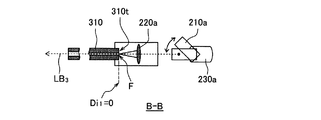
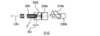
以下、本実施形態を、図4〜図5Dを参照しながら説明する。図4は、ビーム光路切替部の内部構成を模式的に示す平面図である。図5Aは、図4のビーム光路切替部をA−A面側から見た側面図である。図5B〜5Dは、図4のビーム光路切替部をそれぞれB−B面、C−C面およびD−D面側から見た側面図である。図中、同様の構成および機能を備える部材には、同じ符号を付している。なお、レーザ発振器100、プロセスファイバ300、加工ヘッド400、加工テーブル500および加工制御部600は、例えば、第1実施形態と同様の構成を備える。第2反射ミラー210およびステッピングモータ230の構成あるいは動作もまた、第1実施形態と同様であってもよい。各第2集光レンズ220の光学的な物性(焦点距離を含む)は互いに同じであってもよいし、異なっていてもよい。以下、複数の第2集光レンズ220が、いずれも同じ光学的物性を有する場合を例に挙げて説明する。
Hereinafter, the present embodiment will be described with reference to FIGS. 4 to 5D. FIG. 4 is a plan view schematically showing the internal configuration of the beam optical path switching unit. 5A is a side view of the beam optical path switching unit of FIG. 4 as viewed from the AA plane side. 5B to 5D are side views of the beam path switching unit of FIG. 4 as viewed from the BB plane, CC plane, and DD plane, respectively. In the figure, members having the same configuration and function are denoted by the same reference numerals. Note that the
複数の第2集光レンズ220とこれに対応する複数のプロセスファイバ300とは、入射距離Diが互いに異なるように配置されている。例えば、上記のように、第2集光レンズ220a〜220cの光学的物性がいずれも同じである場合、複数の第2集光レンズ220から、これに対応する複数のプロセスファイバ300の入射端300tまでの物理的な距離が、互いに異なるように配置されている。図4では、各第2集光レンズ220を固定し、プロセスファイバ310〜330の入射端の位置をそれぞれ変えて配置している。
The plurality of
図示例において、プロセスファイバ310は、その入射端310tが第2集光レンズ221の焦点位置Fに一致するように、配置されている。そのため、レーザビームLB2のプロセスファイバ310に入射するときの入射ビーム径Dbiは、焦点ビーム径Dbfと同じである。一方、プロセスファイバ320および330の入射端(320t、330t)は、これに対応する第2集光レンズ(222、223)の焦点位置Fとは一致していない。つまり、レーザビームLB2は、デフォーカスされた状態でプロセスファイバ320あるいはプロセスファイバ330に入射する。そのため、レーザビームLB2のプロセスファイバ320あるいはプロセスファイバ330に入射するときのビーム径(入射ビーム径Dbi)は、焦点ビーム径Dbfよりも大きい。
In the illustrated example, the
例えば、第2集光レンズ220a〜220cの焦点距離Dfがいずれも100mmの場合、ビーム径20mmのレーザビームLB1を集光させると、その焦点位置Fでの焦点ビーム径Dbfは約80μmになる。上記のようにプロセスファイバ310を配置する場合、つまり、入射距離Di1が0mmになるようにプロセスファイバ310を配置する場合、上記レーザビームLB1を第2集光レンズ220aで集光させて、プロセスファイバ310に入射させるときのレーザビームLB2の入射ビーム径Dbiは、焦点ビーム径と同じ(約80μm)である。
For example, if the focal length Df both the 100mm of the
プロセスファイバ320を、入射距離Diが80mmになるように配置する場合、上記レーザビームLB1を第2集光レンズ220bで集光させて、プロセスファイバ320に入射させるときのレーザビームLB2の入射ビーム径Dbiは、約160μmになる。プロセスファイバ330を、入射距離Diが60mmになるように配置する場合、上記レーザビームLB1を第2集光レンズ220cで集光させて、プロセスファイバ330に入射させるときのレーザビームLB2の入射ビーム径Dbiは、約240μmになる。
When the
本実施形態も同様に、複数のプロセスファイバ300のコア径は互いに異なる。プロセスファイバ300のコア径は、入射距離Di(つまり、入射ビーム径Dbi)に応じて決定される。例えば、プロセスファイバ300のコア径は、入射ビーム径Dbiの115〜140%であることが好ましい。これにより、所望のレーザビームLB4のBPPが得られ易くなるとともに、レーザビームLB2がプロセスファイバ300に入射する際のエネルギーロスが少なくなって、生産性が向上する。
Similarly, in this embodiment, the core diameters of the plurality of
上記の場合、プロセスファイバ310のコア径は最も小さくてよく、例えば約100μmであればよい。プロセスファイバ310から出射されるレーザビームLB4のBPPは、約4mm・mradになる。プロセスファイバ330のコア径は最も大きく、例えば約300μmであればよい。プロセスファイバ330から出射されるレーザビームLB4のBPPは、約12mm・mradになる。プロセスファイバ320のコア径は、例えば約200μmであればよい。プロセスファイバ320から出射されるレーザビームLB4のBPPは、約8mm・mradになる。
In the above case, the core diameter of the
上記のように、本実施形態では、入射距離Diが異なるように、第2集光レンズ220とプロセスファイバ300とを配置するとともに、配置されるプロセスファイバ300のコア径を、第2集光レンズ220で集光されたレーザビームLB2の入射ビーム径Dbiに応じたものにする。これにより、光学的に同じ第2集光レンズを用いた場合であっても、1台のレーザ発振器から出射されたレーザビームLB1の光路を適宜切り替えて、BPPの異なる複数のレーザビームLB4を生成することができる。その結果、加工内容、ワークWの厚みや材質、加工形状等に応じたBPPを有するレーザビームLBを用いて、ワークWをレーザ加工することができる。
As described above, in the present embodiment, the
本発明のレーザ加工装置によれば、加工内容、ワークの厚みや材質、加工形状等に応じたレーザビームを出射できるため、加工精度および生産性が向上とともに、高い汎用性を備える。 According to the laser processing apparatus of the present invention, it is possible to emit a laser beam according to the processing content, the thickness and material of the workpiece, the processing shape, and the like, so that the processing accuracy and productivity are improved and high versatility is provided.
1000:レーザ加工装置
100:レーザ発振器
200、200A、200B:ビーム光路切替部
210、210a〜210c:第2反射ミラー
220、220a〜220c、221、222、223:第2集光レンズ
230、230a〜230c:ステッピングモータ
240:ビームアブソーバ
250:導光路
300、310、320、330:プロセスファイバ
300t、310t、320t、330t:入射端
400:加工ヘッド
410:コリメータレンズ
420:第1集光レンズ
500:加工テーブル
600:加工制御部
710:X軸モータ
720:Y軸モータ
2000:レーザ加工装置
2100:レーザ発振器
2200:ビーム光路切替部
2210、2210a〜2210c:反射ミラー
2220、2221〜2223:集光レンズ
2300、2300a〜2300c:プロセスファイバ
2400:加工ヘッド
2410:コリメータレンズ
2420:集光レンズ
2500:加工テーブル
2600:加工制御部
2710:X軸モータ
2720:Y軸モータ
1000: Laser processing apparatus 100:
Claims (2)
前記レーザ発振器から出射されるレーザビームが通る複数の光路と、
前記レーザ発振器から出射される前記レーザビームを、前記複数の光路から選択される1つに導光するビーム光路切替部と、
前記複数の光路にそれぞれ配置される複数のプロセスファイバと、
前記複数のプロセスファイバのそれぞれに対応するように前記複数の光路に配置されており、前記レーザビームを集光して、対応する前記プロセスファイバに導光する複数の集光レンズと、を備え、
前記複数の集光レンズが、互いに異なる焦点距離を有し、
前記複数のプロセスファイバがそれぞれ、対応する前記集光レンズの前記焦点距離に応じたコア径を有する、レーザ加工装置。 A laser oscillator;
A plurality of optical paths through which a laser beam emitted from the laser oscillator passes;
A beam optical path switching unit for guiding the laser beam emitted from the laser oscillator to one selected from the plurality of optical paths;
A plurality of process fibers respectively disposed in the plurality of optical paths;
A plurality of condensing lenses disposed in the plurality of optical paths so as to correspond to the plurality of process fibers, respectively, condensing the laser beam and guiding the laser beams to the corresponding process fibers,
The plurality of condensing lenses have different focal lengths;
The laser processing apparatus, wherein each of the plurality of process fibers has a core diameter corresponding to the focal length of the corresponding condensing lens.
前記レーザ発振器から出射されるレーザビームが通る複数の光路と、
前記レーザ発振器から出射される前記レーザビームを、前記複数の光路から選択される1つに導光するビーム光路切替部と、
前記複数の光路に配置される複数のプロセスファイバと、
前記複数のプロセスファイバのそれぞれに対応するように前記複数の光路に配置されており、前記レーザビームを集光して、対応する前記プロセスファイバに導光する複数の集光レンズと、を備え、
前記複数の集光レンズの焦点位置から、それぞれ対応する前記複数のプロセスファイバの前記レーザビームが入射する入射端までの入射距離が、互いに異なっており、
前記複数のプロセスファイバがそれぞれ、対応する前記焦点位置からの前記入射距離に応じたコア径を有する、レーザ加工装置。 A laser oscillator;
A plurality of optical paths through which a laser beam emitted from the laser oscillator passes;
A beam optical path switching unit for guiding the laser beam emitted from the laser oscillator to one selected from the plurality of optical paths;
A plurality of process fibers disposed in the plurality of optical paths;
A plurality of condensing lenses disposed in the plurality of optical paths so as to correspond to the plurality of process fibers, respectively, condensing the laser beam and guiding the laser beams to the corresponding process fibers,
The incident distances from the focal positions of the plurality of condenser lenses to the incident ends on which the laser beams of the plurality of corresponding process fibers are incident are different from each other,
The laser processing apparatus, wherein each of the plurality of process fibers has a core diameter corresponding to the incident distance from the corresponding focal position.
Priority Applications (1)
| Application Number | Priority Date | Filing Date | Title |
|---|---|---|---|
| JP2016178350A JP2018043256A (en) | 2016-09-13 | 2016-09-13 | Laser machining device |
Applications Claiming Priority (1)
| Application Number | Priority Date | Filing Date | Title |
|---|---|---|---|
| JP2016178350A JP2018043256A (en) | 2016-09-13 | 2016-09-13 | Laser machining device |
Publications (1)
| Publication Number | Publication Date |
|---|---|
| JP2018043256A true JP2018043256A (en) | 2018-03-22 |
Family
ID=61692347
Family Applications (1)
| Application Number | Title | Priority Date | Filing Date |
|---|---|---|---|
| JP2016178350A Pending JP2018043256A (en) | 2016-09-13 | 2016-09-13 | Laser machining device |
Country Status (1)
| Country | Link |
|---|---|
| JP (1) | JP2018043256A (en) |
Cited By (1)
| Publication number | Priority date | Publication date | Assignee | Title |
|---|---|---|---|---|
| CN108907454A (en) * | 2018-09-20 | 2018-11-30 | 无锡源清瑞光激光科技有限公司 | Single beam time-division switching module for laser spot welding system of processing |
Citations (3)
| Publication number | Priority date | Publication date | Assignee | Title |
|---|---|---|---|---|
| JPH06344170A (en) * | 1993-06-11 | 1994-12-20 | Fuji Electric Co Ltd | Laser processing equipment |
| JP2003211279A (en) * | 2002-01-16 | 2003-07-29 | Ricoh Microelectronics Co Ltd | Method and device of beam machining |
| JP2009160658A (en) * | 2009-04-06 | 2009-07-23 | Toshiba Corp | Laser beam irradiation device |
-
2016
- 2016-09-13 JP JP2016178350A patent/JP2018043256A/en active Pending
Patent Citations (3)
| Publication number | Priority date | Publication date | Assignee | Title |
|---|---|---|---|---|
| JPH06344170A (en) * | 1993-06-11 | 1994-12-20 | Fuji Electric Co Ltd | Laser processing equipment |
| JP2003211279A (en) * | 2002-01-16 | 2003-07-29 | Ricoh Microelectronics Co Ltd | Method and device of beam machining |
| JP2009160658A (en) * | 2009-04-06 | 2009-07-23 | Toshiba Corp | Laser beam irradiation device |
Cited By (1)
| Publication number | Priority date | Publication date | Assignee | Title |
|---|---|---|---|---|
| CN108907454A (en) * | 2018-09-20 | 2018-11-30 | 无锡源清瑞光激光科技有限公司 | Single beam time-division switching module for laser spot welding system of processing |
Similar Documents
| Publication | Publication Date | Title |
|---|---|---|
| JP7119094B2 (en) | Laser processing apparatus and method | |
| TWI758365B (en) | Laser processing apparatus and method | |
| US11351633B2 (en) | Laser processing apparatus and method | |
| JP5639046B2 (en) | Laser processing apparatus and laser processing method | |
| KR102364889B1 (en) | Laser processing apparatus and method and optical components therefor | |
| JP5535423B2 (en) | How to cut stainless steel with fiber laser | |
| RU2750313C2 (en) | Method for laser processing of metal material with a high level of dynamic control of the axes of movement of the laser beam along a pre-selected processing path, as well as a machine and a computer program for implementing this method | |
| US20220168841A1 (en) | Method for flame cutting by means of a laser beam | |
| JP2013180295A (en) | Machining apparatus and machining method | |
| JP2018034184A (en) | Laser oscillator and laser machining apparatus | |
| WO2012050098A1 (en) | Laser processing device and laser processing method | |
| JP2009178720A (en) | Laser beam machining apparatus | |
| JP6895621B2 (en) | Laser processing head and laser processing equipment | |
| GB2582331A (en) | Apparatus for laser processing a material | |
| JP2018043256A (en) | Laser machining device | |
| JP6043773B2 (en) | Sheet metal processing method using direct diode laser light and direct diode laser processing apparatus for executing the same | |
| JP6643442B1 (en) | Laser processing machine and laser processing method | |
| JP2018043257A (en) | Laser machining device | |
| JP2013176800A (en) | Processing device and processing method | |
| US11697176B2 (en) | Laser machining apparatus and laser machining method | |
| CN116323075A (en) | Beam shaping system in laser welding process | |
| JP2020009851A (en) | Laser oscillator and control method thereof | |
| JP2016153143A (en) | Processing method for sheet metal with direct diode laser beam and direct laser processing apparatus for executing the same |
Legal Events
| Date | Code | Title | Description |
|---|---|---|---|
| RD02 | Notification of acceptance of power of attorney |
Free format text: JAPANESE INTERMEDIATE CODE: A7422 Effective date: 20180709 |
|
| A621 | Written request for application examination |
Free format text: JAPANESE INTERMEDIATE CODE: A621 Effective date: 20190626 |
|
| A977 | Report on retrieval |
Free format text: JAPANESE INTERMEDIATE CODE: A971007 Effective date: 20200722 |
|
| A131 | Notification of reasons for refusal |
Free format text: JAPANESE INTERMEDIATE CODE: A131 Effective date: 20200811 |
|
| A02 | Decision of refusal |
Free format text: JAPANESE INTERMEDIATE CODE: A02 Effective date: 20210302 |