JP2018028362A - Range switching device - Google Patents
Range switching device Download PDFInfo
- Publication number
- JP2018028362A JP2018028362A JP2016160970A JP2016160970A JP2018028362A JP 2018028362 A JP2018028362 A JP 2018028362A JP 2016160970 A JP2016160970 A JP 2016160970A JP 2016160970 A JP2016160970 A JP 2016160970A JP 2018028362 A JP2018028362 A JP 2018028362A
- Authority
- JP
- Japan
- Prior art keywords
- rotation angle
- motor
- angle detection
- detection device
- range
- Prior art date
- Legal status (The legal status is an assumption and is not a legal conclusion. Google has not performed a legal analysis and makes no representation as to the accuracy of the status listed.)
- Granted
Links
Images
Landscapes
- Gear-Shifting Mechanisms (AREA)
Abstract
【課題】製品の大型化を招くことなく、回転角度検出装置をモータの近傍に配置することができて、回転角度検出装置の検出精度の低下を抑制することができるレンジ切り替え装置を提供する。【解決手段】モータ14により駆動される駆動軸15と、駆動軸15のトルクを増幅する減速歯車装置16と、自動変速機のシフトシャフトと噛合してトルクをシフトシャフトへ伝達する出力軸17と、出力軸17の回転角度を検出する回転角度検出装置18を備え、出力軸17の可動角度範囲のいずれかの位置において、回転角度検出装置18が検知するセンサーマグネット34による磁界の方向が、モータ14の中心と回転角度検出装置18の中心とを結ぶ線と平行となるように構成した。【選択図】図2Kind Code: A1 A range switching device is provided in which a rotation angle detection device can be arranged in the vicinity of a motor without increasing the size of the product, and a decrease in detection accuracy of the rotation angle detection device can be suppressed. A drive shaft (15) driven by a motor (14), a reduction gear device (16) that amplifies the torque of the drive shaft (15), and an output shaft (17) that meshes with a shift shaft of an automatic transmission to transmit the torque to the shift shaft. , a rotation angle detection device 18 for detecting the rotation angle of the output shaft 17, and at any position in the movable angle range of the output shaft 17, the direction of the magnetic field by the sensor magnet 34 detected by the rotation angle detection device 18 is the direction of the motor. 14 and the center of the rotation angle detection device 18 so as to be parallel to the line. [Selection drawing] Fig. 2
Description
この発明は、車両の自動変速機のレンジ切り替えを電気信号を介して操作するレンジ切り替え装置に関するものである。 The present invention relates to a range switching device that operates range switching of an automatic transmission of a vehicle via an electrical signal.
近年、車両制御において、例えば特開2016−89967号公報(特許文献1)に開示されているように、車両操縦者の指令により車両の自動変速機のシフトレンジを電気信号で切り替えるレンジ切り替え装置を備えたシフトバイワイヤシステムが採用されている。
レンジ切り替え装置は、自動変速機の上面や側面などに固定されて、自動変速機とエンジンあるいはボンネットなどとの間の狭小スペースに搭載されて使用されることから、外形サイズが小型であることが求められる。
さらに、レンジ位置を検知するための回転角度検出装置を、レンジ切り替え装置に内蔵するものがある。これにより得られるレンジ位置情報や回転角度の情報は、レンジ切り替え装置におけるモータ駆動のための制御情報として使用されるとともに、トランスミッションコントロールユニットなど関連する他のシステムやユニットへも伝達される。
In recent years, in vehicle control, for example, as disclosed in JP-A-2006-89967 (Patent Document 1), a range switching device that switches a shift range of an automatic transmission of a vehicle with an electrical signal according to a command from a vehicle operator. The provided shift-by-wire system is adopted.
The range switching device is fixed to the top surface or side surface of the automatic transmission and mounted in a narrow space between the automatic transmission and the engine or bonnet. Desired.
Further, there is a type in which a rotation angle detection device for detecting the range position is built in the range switching device. Range position information and rotation angle information obtained in this way are used as control information for driving the motor in the range switching device, and are also transmitted to other related systems and units such as a transmission control unit.
従来のシフトバイワイヤシステムのレンジ切り替え装置においては、上記のように外形サイズの小型化要求に応えるために、減速機構部の軸間ピッチをできる限り小さく配置した構成で小型化を行っている。その結果、回転角度検出装置がモータの近傍に配置されることとなり、センサーマグネットの磁界には、モータから漏れ出した磁界がノイズとして重畳してしまうことにより、角度の検出精度が低下する問題があった。 In a conventional shift-by-wire system range switching device, downsizing is performed with a configuration in which the pitch between the shafts of the speed reduction mechanism is as small as possible in order to meet the demand for downsizing of the outer size as described above. As a result, the rotation angle detection device is arranged in the vicinity of the motor, and the magnetic field leaked from the motor is superimposed on the magnetic field of the sensor magnet as noise, which causes a problem that the angle detection accuracy decreases. there were.
これに対しては、モータの漏れ磁界を遮蔽するためのシールド部品によってセンサを包囲することで、回転角度検出装置へ重畳するモータの漏れ磁界を抑制するような対策、あるいは、モータの漏れ磁界が及ばない位置まで、回転角度検出装置を離して設置する対策が考えられる。しかしながらこれらの対策によれば、シールド部品を設置するためのスペースが必要となり製品の大型化を招いたり、あるいは、回転角度検出装置をモータから離して設置することで、再び製品の大型化を招いてしまう問題がある。 For this, measures to suppress the leakage magnetic field of the motor superimposed on the rotation angle detection device by surrounding the sensor with a shielding component for shielding the leakage magnetic field of the motor, or the leakage magnetic field of the motor Measures can be considered in which the rotation angle detection device is set apart to a position that does not reach. However, according to these measures, a space for installing shield parts is required, which leads to an increase in the size of the product, or the rotation angle detector is installed away from the motor, thereby increasing the size of the product again. There is a problem.
この発明は、上記のような課題を解決するためになされたものであり、製品の大型化を招くことなく、回転角度検出装置をモータの近傍に配置することができて、回転角度検出装置の検出精度の低下を抑制することができるレンジ切り替え装置を提供することを目的とするものである。 The present invention has been made to solve the above-described problems. The rotation angle detection device can be disposed near the motor without causing an increase in the size of the product. An object of the present invention is to provide a range switching device that can suppress a decrease in detection accuracy.
上記の問題を解決するために、この発明に係るレンジ切り替え装置は、モータにより駆動される駆動軸と、前記駆動軸のトルクを増幅する減速歯車装置と、自動変速機のシフトシャフトと噛合してトルクをシフトシャフトへ伝達する出力軸と、前記出力軸の回転角度を検出する回転角度検出装置を備え、
前記出力軸の可動角度範囲のいずれかの位置において、前記回転角度検出装置が検知す
るセンサーマグネットによる磁界の方向が、前記モータの中心と前記回転角度検出装置の中心とを結ぶ線と平行となるように構成したことを特徴とする。
In order to solve the above problems, a range switching device according to the present invention is engaged with a drive shaft driven by a motor, a reduction gear device that amplifies the torque of the drive shaft, and a shift shaft of an automatic transmission. An output shaft that transmits torque to the shift shaft, and a rotation angle detection device that detects a rotation angle of the output shaft;
At any position in the movable angle range of the output shaft, the direction of the magnetic field by the sensor magnet detected by the rotation angle detection device is parallel to a line connecting the center of the motor and the center of the rotation angle detection device. It is configured as described above.
この発明のレンジ切り替え装置によれば、回転角度検出装置をモータの近傍に配置しても、回転角度検出装置の検出精度の低下を回避することができて、製品の小型化を可能にすることができる。 According to the range switching device of the present invention, even if the rotation angle detection device is arranged in the vicinity of the motor, it is possible to avoid a decrease in the detection accuracy of the rotation angle detection device and to reduce the size of the product. Can do.
以下、この発明によるレンジ切り替え装置の好適な実施の形態について図面を参照して詳細に説明する。なお、各図面において、同一符号は同一あるいは相当部分を示す。 Preferred embodiments of a range switching device according to the present invention will be described below in detail with reference to the drawings. In the drawings, the same reference numerals denote the same or corresponding parts.
実施の形態1.
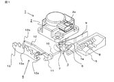
図1は、この発明の実施の形態1に係るレンジ切り替え装置を備えたシフトバイワイヤシステムの全体構成を示す斜視図である。図1においてシフトバイワイヤシステム1は、レンジ切り替え装置2と、ディテント機構3と、パーキング機構4およびバルブボディ5を備えている。
FIG. 1 is a perspective view showing an overall configuration of a shift-by-wire system including a range switching device according to
ここで、レンジ切り替え装置2は、例えば、車両に搭載される自動変速機に取り付けられて構成されており、車両操縦者によって選択されるシフトレバー(レンジ選択手段)からのシフト信号(電気信号)が供給されるコネクタ2aを備えている。このシフト信号に基づいてレンジ切り替え装置2は、図2において説明する出力軸17に連結された駆動対象となるシフトシャフト6を回転駆動させ、このシフトシャフト6に取り付けられた略扇形状のディテントプレート7を正逆に回転させる。ディテントプレート7には、スプール弁8が連動するように取り付けられており、シフトシャフト6の回転によりディテントプレート7が回転すると、連動するスプール弁8がバルブボディ5の内部で往復移動し、これによってバルブボディ5の内部の油路を切り替えて、所定のレンジ位置(P、R、N、D)に設定するように構成されている。
Here, the
また、ディテントプレート7には、略扇形状の先端部に複数の凹部7aが設けられており、この凹部7aは、スプール弁8の各レンジ位置(P、R、N、D)に対応している。さらに、ディテントスプリング9が板バネとして作用し、その先端を凹部7aに押圧することによって、ディテントプレート7を位置決め保持するように構成されている。
Further, the
一方、パーキング機構4は、ディテントプレート7に連結されたパーキングロッド10と、パーキングロッド10の先端に設けられた円錐部11と、パーキングポール12と、
パーキングギヤ13とを有している。パーキングロッド10は、ディテントプレート7の正逆の回転運動に伴い、パーキングロッド10の位置が変わることによって、その先端に設けられた円錐部11を介してパーキングポール12が、軸12aを中心に上下にシーソー運動する。この運動に伴い、パーキングポール12の凸部12bが、パーキングギヤ13の凹部13aに嵌合あるいは凹部13aから離脱することによってパーキング機構4のロックとアンロックが実行され、自動変速機におけるパーキングギヤ13の回転を阻止または可能とすることになる。
On the other hand, the
And a
以上のように、シフトバイワイヤシステム1においては、ディテントプレート7を介してシフトシャフト6とスプール弁8とが連動していることから、シフトシャフト6の回転角度を制御することによって、スプール弁8の位置を制御し、所定のレンジ位置に設定することが可能となるものである。
As described above, in the shift-by-
なお、車両やシステムによって違いはあるものの、PレンジからDレンジ間のレンジ切り替えにより、シフトシャフト6およびディテントプレート7は、一般的には50度程度回転する。
Although there is a difference depending on the vehicle and the system, the
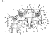
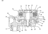
次に、レンジ切り替え装置2の構成および動作を図2にもとづいて説明する。レンジ切り替え装置2は、モータ14と、モータ14により駆動される駆動軸15と、駆動軸15のトルクを増幅する減速歯車装置16と、減速歯車装置16で増幅されたトルクを、車両のシフトシャフト6に伝達する出力軸17と、出力軸17の回転角度を検出する回転角度検出装置18で構成され、これらはハウジング19とカバー20により格納される。
Next, the configuration and operation of the
モータ14は、永久磁石を用いたブラシレスモータであり、回転可能に支持されたロータ21と、このロータ21の回転中心と同軸上に配置されたステータ22とで構成されている。ロータ21は駆動軸15に固定されており、磁石23はロータ21に接着等の手段により固定されている。磁石23は周方向に複数の極に着磁されている。
駆動軸15は、転がり軸受24および25によってハウジング19に回転可能に保持されている。また、出力軸17と駆動軸15の軸中心は離間して配置され、小歯車26と大歯車27の噛合によって連動される。
The
The
ステータ22は、ステータコア28及びコイル29から構成されている。ステータコア28には、径内方向に向けて突出する複数のステータティースが形成されており、各ステータティースにはコイル29が巻回されて、それぞれU相、V相、及びW相を形成して3相モータの固定子結線を構成している。
The
減速歯車装置16は、遊星歯車減速機構と平歯車減速機構によって構成されており、回転する駆動軸15に取付けられた太陽歯車30と、この太陽歯車30に噛み合う遊星歯車31と、遊星歯車31に噛み合う内歯32aを内周面に有するとともに外周部に磁性材からなる環状のギヤケース32bを備えた環状歯車32と、遊星歯車31を自転及び公転可能に支持するピン33aを有するキャリア33と、遊星歯車31と反対面側のキャリア33に取付けられた小歯車26と、出力軸17に固定され小歯車26に噛み合う大歯車27を有している。大歯車27は内歯が形成されて小歯車26と噛合する。
The
出力軸17の端部にはセンサーマグネット34が設置されており、センサーマグネット34と対向する位置には、出力軸17の回転角度を検出する回転角度検出装置18が配置されている。回転角度検出装置18は、磁束の方向を検知する磁気抵抗素子であり、図2における矢印φで示す水平方向の磁束を検出する向きに配置される。
センサーマグネット34の端面は、径方向に磁束を発生させることができるように2極に着磁されており、回転角度検出装置18の位置において、水平方向で所定の磁束密度の
磁束が発生するように回転角度検出装置18から所定距離だけ離間して配置されている。
A
The end surface of the
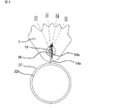
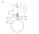
図3には、ディテントプレート7に形成された各レンジと、センサーマグネット34の磁束の方向との位置関係を模式的に示している。実施の形態1においては、ディテントプレート7がPレンジとDレンジとの中間位置にある時に、センサーマグネット34の磁束34aの方向が、モータ14の中心と回転角度検出装置18の中心とを結ぶ線と平行となるようにセンサーマグネット34を配置している。
FIG. 3 schematically shows the positional relationship between each range formed on the
上記の構成によるレンジ切り替え装置2において、車両操縦者により選択されるシフトレバー(レンジ選択手段)からのシフト信号が入力されると、モータ14のコイル29には、駆動軸15を回転させるための回転磁界を発生させる電流が流されて、駆動軸15が回転する。そして駆動軸15に発生するトルクは減速歯車装置16により増幅されて、出力軸17を経てシフトシャフト6に伝達される。これによりディテントプレート7が回転して、目標のレンジへの切り替えが実行される。
In the
ここで、ギヤケース32bは、モータ14から漏れ出す磁界を集磁して再びモータ14へ戻すための磁気誘導部材となっている。これによりモータ14からの漏れ磁束14aは、ステータ22の外周面から漏れ出して、ギヤケース32bやロータ21へ向かって、図3の下方へ向かいながらギヤケース32bの径内方向へ流れる。同様に、ロータ21からの漏れ磁束14aは、同様の経路をステータ22に向けて逆方向に流れる。このような漏れ磁束の交番挙動は、回転磁界を発生させるための通電相の切り換えに伴って交互に発生する。
Here, the
このような磁束の流れにおいて、回転角度検出装置18の位置においては、センサーマグネット34の磁束34aとモータ14からの漏れ磁束14aが通過するが、このうち、回転角度検出装置18が検知するのは、センサーマグネット34の磁束34aと漏れ磁束14aの水平成分との合成磁束の方向である。
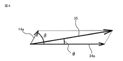
この関係を模式的に示したものが図4である。センサーマグネット34の磁束34aと漏れ磁束14aとが交差する角度をβとした場合、漏れ磁束14aの重畳により、回転角度検出装置18が検知する磁束は、センサーマグネット34の磁束34aに対してθだけ傾けられることを示している。
In such a flow of magnetic flux, the
FIG. 4 schematically shows this relationship. When the angle at which the
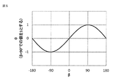
図5には、センサーマグネット34の磁束34aと漏れ磁束14aとを単一方向のベクトルとしてモデル化した場合の、角度βに対する角度θの変化を示す。なお、角度θの値は、β=90°におけるθの値を1とした時の割合で示す。
これによれば、センサーマグネット34の磁束34aと漏れ磁束14aとの交差する角度βが、90°ないし−90°に近づくにつれて、センサーマグネット34の磁束34aに対する合成磁束35の傾き角度θの絶対値は大きくなる。すなわち、回転角度検出装置18で検出される出力軸17の回転角度は、θで示される角度の分の誤差を生じることになる。
言い換えれば、センサーマグネット34の磁束34aと漏れ磁束14aの水平成分とが平行に近づくほど、漏れ磁束14aの重畳による影響は小さくなり、前記の誤差θは小さくなる。
FIG. 5 shows a change in the angle θ with respect to the angle β when the
According to this, as the angle β at which the
In other words, as the
実施の形態1においては、図3に示すように、ディテントプレート7がPレンジとDレ
ンジとの中間位置にある時に、センサーマグネット34の磁束34aの方向が、モータ14の中心と回転角度検出装置18の中心とを結ぶ線と平行となるよう配置しているので、この位置において、回転角度検出装置18による検出角度の誤差が最も小さくなる。さらに可動範囲の両端であるPレンジおよびDレンジであっても、センサーマグネット34の磁束34aの方向は、漏れ磁束14aと直交はしない。
In the first embodiment, as shown in FIG. 3, when the
これにより、PレンジからDレンジまでの全範囲において、センサーマグネット34の磁束34aと漏れ磁束14aとが直交することがなく、さらに、可動範囲の全般で検出誤差θが小さい領域を使用することができるので、回転角度検出装置18の検出精度の低下が抑えられる。
As a result, in the entire range from the P range to the D range, the
これまで説明したように、実施の形態1のレンジ切り替え装置によれば、センサーマグネット34の磁束34aの方向とモータ14からの漏れ磁束14aの水平成分とが、直交することなく平行に近くなる配置にしているので、漏れ磁束14aの重畳による影響を最小限に抑えることができて、回転角度検出装置18の検出精度の低下を抑えることができる。これにより、モータ14の近傍に回転角度検出装置18を設置することが可能となる。そしてモータ14の漏れ磁界14aの影響を受けないようにするために、回転角度検出装置18をモータ14から離れた位置に設置する対策を行った場合と比べて、レンジ切り替え装置を小型に構成することが可能となる。
As described so far, according to the range switching device of the first embodiment, the arrangement in which the direction of the
さらに、ロータ21とステータ22の極数が多い多極のモータ14を使用する場合であっても、モータ14から放射状に漏れ出す磁束を、磁気誘導部材である環状歯車32によって集磁することができる。このため、使用するモータ14の極数の制約を受けることなく、回転角度検出装置18の検出精度の低下を抑えることができる。
Further, even when the
なお、実施の形態1においては、環状歯車32を磁気誘導部材としたが、この形態に限定されるものではなく、モータ14の中心軸と同心の略扇型ないし略円環状に形成しても良い。この場合、磁気誘導部材の外周長さは、モータ14の周方向に沿った回転角度検出装置18の長さ以上であればよく、内周の位置は、ロータ21の外周位置よりも径内方向の位置であれば同様の効果を得ることができる。
In the first embodiment, the
実施の形態2.
次に、この発明の実施の形態2に係るレンジ切り替え装置について説明する。図6は、実施の形態2に係るレンジ切り替え装置を説明する図で、実施の形態1の図3に相当する図である。実施の形態2に係るレンジ切り替え装置は、シフトシャフト6がPレンジ位置にある状態において、センサーマグネット34の磁束34aの方向が、モータ14の中心と回転角度検出装置18の中心とを結ぶ線と平行となるようにセンサーマグネット34を配置している。なお、その他の構成は実施の形態と同様であり、説明を省略する。
Next, a range switching apparatus according to
Pレンジにおいては、車両を安全に停車させるために、円錐部11を所定位置まで確実に移動させて、パーキングポール12がパーキングギヤ13へ嵌合させることが必要となる。このためレンジ切り替え装置2に対しては、Pレンジ位置への正確な位置決め動作が求められる。
In the P range, in order to stop the vehicle safely, it is necessary to securely move the
この場合であっても、実施の形態2によれば、Pレンジの位置にて、センサーマグネット34の磁束34aの方向と、モータ14の漏れ磁束14aとが平行に配置されているので、Pレンジの位置での回転角度検出装置18の検出精度の低下は抑えられて、レンジ切り替え装置2による正確な位置決めを行うことができる。
Even in this case, according to the second embodiment, the direction of the
実施の形態2においては、Pレンジの状態において、センサーマグネット34の磁束34aの方向が、モータ14の中心と回転角度検出装置18の中心とを結ぶ線と平行となるようにセンサーマグネット34を配置しているが、これに限定されるものではない。
すなわち、ディテントプレート7によって規定されるいずれかのレンジの位置において、センサーマグネット34の磁束34aの方向が、モータ14の中心と回転角度検出装置18の中心とを結ぶ線と平行となるように配置することで、そのレンジの位置での回転角度検出装置18の検出精度の低下を抑え、レンジ切り替え装置2による正確な位置決めを行うことができる。
In the second embodiment, the
In other words, the
実施の形態3.
次に、この発明の実施の形態3に係るレンジ切り替え装置について説明する。図7は、実施の形態3に係るレンジ切り替え装置を説明する図で、実施の形態1の図2に相当する図である。実施の形態3に係るレンジ切り替え装置は、ピン33aの端部に磁性材料からなる円板状部材36が固定されている。なお、その他の構成は実施の形態と同様であり、説明を省略する。
Embodiment 3 FIG.
Next, a range switching apparatus according to Embodiment 3 of the present invention will be described. FIG. 7 is a diagram for explaining the range switching device according to the third embodiment, and corresponds to FIG. 2 of the first embodiment. In the range switching device according to the third embodiment, a disk-
これによれば、環状歯車32を樹脂や真鍮などの非磁性材料で構成した場合であっても、加工が容易な円板状部材36を用いて磁気誘導部材を構成することができる。また、円板状部材36はキャリア33とともに回転運動を行うが、円板状に形成されているので、回転しても磁気誘導部材としての磁気通路の長さは変化しない。従って、モータ14からの漏れ磁束14aを集磁することができて、既述の実施の形態と同様の効果が得られる。
According to this, even if the
なお、上記の各実施の形態においては、モータ14をブラシレスモータとして説明したが、これに限定されるものではなく、ブラシ付きモータであっても、この発明の適用によって同様の効果を得ることができる。また、モータ14はラジアルギャップを有したインナーロータ式モータとして説明したが、これに限定されるものではなく、アウターロータ式モータで構成してもよく、さらにはアキシャルギャップを有したモータであってもよい。
In each of the above embodiments, the
また、この発明は、その発明の範囲内において、各実施の形態を自由に組み合わせたり、各実施の形態を適宜、変形、省略したりすることが可能である。 In addition, within the scope of the present invention, the embodiments can be freely combined, or the embodiments can be appropriately modified or omitted.
1 シフトバイワイヤシステム、2 レンジ切り替え装置、2a コネクタ、3 ディテント機構、4 パーキング機構、5 バルブボディ、6 シフトシャフト、7 ディテントプレート、7a 凹部、8 スプール弁、9 ディテントスプリング、10 パーキングロッド、11 円錐部、12 パーキングポール、12a 軸、12b 凸部、13 パーキングギヤ、13a 凹部、14 モータ、15 駆動軸、16 減速歯車装置、17 出力軸、18 回転角度検出装置、19 ハウジング、20 カバー、21 ロータ、22 ステータ、23 磁石、24、25 転がり軸受、26 小歯車、27 大歯車、28 ステータコア、29 コイル、30 太陽歯車、31 遊星歯車、32 環状歯車、32a 内歯、32b ギヤケース、33 キャリア、33a ピン、34 センサーマグネット、34a 磁束、35 合成磁束、36 円板状部材
1 shift-by-wire system, 2 range switching device, 2a connector, 3 detent mechanism, 4 parking mechanism, 5 valve body, 6 shift shaft, 7 detent plate, 7a recess, 8 spool valve, 9 detent spring, 10 parking rod, 11 cone Part, 12 parking pole, 12a shaft, 12b convex part, 13 parking gear, 13a concave part, 14 motor, 15 drive shaft, 16 reduction gear device, 17 output shaft, 18 rotation angle detection device, 19 housing, 20 cover, 21 rotor , 22 Stator, 23 Magnet, 24, 25 Rolling bearing, 26 Small gear, 27 Large gear, 28 Stator core, 29 Coil, 30 Sun gear, 31 Planetary gear, 32 Annular gear, 32a Internal gear, 32b Gear case, 33
Claims (4)
前記出力軸の可動角度範囲のいずれかの位置において、前記回転角度検出装置が検知するセンサーマグネットによる磁界の方向が、前記モータの中心と前記回転角度検出装置の中心とを結ぶ線と平行となるように構成したことを特徴とするレンジ切り替え装置。 A drive shaft driven by a motor; a reduction gear device that amplifies the torque of the drive shaft; an output shaft that meshes with a shift shaft of an automatic transmission and transmits torque to the shift shaft; and a rotation angle of the output shaft. A rotation angle detection device for detecting,
At any position in the movable angle range of the output shaft, the direction of the magnetic field by the sensor magnet detected by the rotation angle detection device is parallel to a line connecting the center of the motor and the center of the rotation angle detection device. A range switching device characterized by being configured as described above.
The range switching device according to claim 3, wherein the magnetic induction member is a component of the reduction gear device.
Priority Applications (1)
| Application Number | Priority Date | Filing Date | Title |
|---|---|---|---|
| JP2016160970A JP6147398B1 (en) | 2016-08-19 | 2016-08-19 | Range switching device |
Applications Claiming Priority (1)
| Application Number | Priority Date | Filing Date | Title |
|---|---|---|---|
| JP2016160970A JP6147398B1 (en) | 2016-08-19 | 2016-08-19 | Range switching device |
Publications (2)
| Publication Number | Publication Date |
|---|---|
| JP6147398B1 JP6147398B1 (en) | 2017-06-14 |
| JP2018028362A true JP2018028362A (en) | 2018-02-22 |
Family
ID=59061226
Family Applications (1)
| Application Number | Title | Priority Date | Filing Date |
|---|---|---|---|
| JP2016160970A Expired - Fee Related JP6147398B1 (en) | 2016-08-19 | 2016-08-19 | Range switching device |
Country Status (1)
| Country | Link |
|---|---|
| JP (1) | JP6147398B1 (en) |
Families Citing this family (1)
| Publication number | Priority date | Publication date | Assignee | Title |
|---|---|---|---|---|
| DE102017216664A1 (en) * | 2017-09-20 | 2019-03-21 | Continental Teves Ag & Co. Ohg | Electric hollow shaft motor |
Citations (3)
| Publication number | Priority date | Publication date | Assignee | Title |
|---|---|---|---|---|
| WO2013061503A1 (en) * | 2011-10-27 | 2013-05-02 | タイコエレクトロニクスジャパン合同会社 | Detecting sensor manufacturing method, detecting sensor, and transmission |
| JP2014059224A (en) * | 2012-09-18 | 2014-04-03 | Tokai Rika Co Ltd | Two-axis position sensor and shift position sensor using the same |
| JP2015200347A (en) * | 2014-04-07 | 2015-11-12 | 三菱電機株式会社 | Range switching device |
-
2016
- 2016-08-19 JP JP2016160970A patent/JP6147398B1/en not_active Expired - Fee Related
Patent Citations (3)
| Publication number | Priority date | Publication date | Assignee | Title |
|---|---|---|---|---|
| WO2013061503A1 (en) * | 2011-10-27 | 2013-05-02 | タイコエレクトロニクスジャパン合同会社 | Detecting sensor manufacturing method, detecting sensor, and transmission |
| JP2014059224A (en) * | 2012-09-18 | 2014-04-03 | Tokai Rika Co Ltd | Two-axis position sensor and shift position sensor using the same |
| JP2015200347A (en) * | 2014-04-07 | 2015-11-12 | 三菱電機株式会社 | Range switching device |
Also Published As
| Publication number | Publication date |
|---|---|
| JP6147398B1 (en) | 2017-06-14 |
Similar Documents
| Publication | Publication Date | Title |
|---|---|---|
| CN109863672B (en) | Rotary actuator, rotary drive and shift-by-wire system using the same | |
| CN102315754B (en) | Actuator | |
| JP5984898B2 (en) | Range switching device | |
| JP5692606B2 (en) | Rotary actuator | |
| KR20190117682A (en) | Electric valve | |
| US10371257B2 (en) | Rotational drive apparatus and shift-by-wire system having the same | |
| US5038066A (en) | Claw pole rotary actuator with limited angular movement | |
| US20160178365A1 (en) | Surveying apparatus with positioning device | |
| JP2016109226A (en) | Rotary actuator | |
| JP2017203521A (en) | Magnetic bearing device and blower | |
| JP2019530400A (en) | Rotor position sensing device and motor including the same | |
| TW201307698A (en) | Ctromagnetic clutch | |
| JPWO2014042268A1 (en) | Relative rotation angle displacement detection device, torque detection device and torque control device using the detection device, and vehicle equipped with the control device | |
| US11079012B2 (en) | Rotary actuator | |
| JP6147398B1 (en) | Range switching device | |
| JP6673142B2 (en) | Rotary drive device and shift-by-wire system using the same | |
| US20160285352A1 (en) | Magnetic brake having reduced-notching hysteresis | |
| JP5126304B2 (en) | Actuator | |
| WO2019065505A1 (en) | Electrical actuator | |
| JP6116735B1 (en) | Range switching device | |
| JP6041437B2 (en) | Rotary actuator | |
| JP2021145520A (en) | Linear actuator | |
| JP2017090073A (en) | Non-contact type rotation angle detector | |
| JP2008286285A (en) | Electromagnetic clutch | |
| JP6116636B2 (en) | Range switching device for shift-by-wire automatic transmission |
Legal Events
| Date | Code | Title | Description |
|---|---|---|---|
| TRDD | Decision of grant or rejection written | ||
| A01 | Written decision to grant a patent or to grant a registration (utility model) |
Free format text: JAPANESE INTERMEDIATE CODE: A01 Effective date: 20170418 |
|
| A61 | First payment of annual fees (during grant procedure) |
Free format text: JAPANESE INTERMEDIATE CODE: A61 Effective date: 20170516 |
|
| R151 | Written notification of patent or utility model registration |
Ref document number: 6147398 Country of ref document: JP Free format text: JAPANESE INTERMEDIATE CODE: R151 |
|
| LAPS | Cancellation because of no payment of annual fees |
