JP2018024220A - Honeycomb structure forming die - Google Patents
Honeycomb structure forming die Download PDFInfo
- Publication number
- JP2018024220A JP2018024220A JP2016220875A JP2016220875A JP2018024220A JP 2018024220 A JP2018024220 A JP 2018024220A JP 2016220875 A JP2016220875 A JP 2016220875A JP 2016220875 A JP2016220875 A JP 2016220875A JP 2018024220 A JP2018024220 A JP 2018024220A
- Authority
- JP
- Japan
- Prior art keywords
- base
- die
- clay
- honeycomb structure
- slit
- Prior art date
- Legal status (The legal status is an assumption and is not a legal conclusion. Google has not performed a legal analysis and makes no representation as to the accuracy of the status listed.)
- Granted
Links
Images


Classifications
-
- B—PERFORMING OPERATIONS; TRANSPORTING
- B28—WORKING CEMENT, CLAY, OR STONE
- B28B—SHAPING CLAY OR OTHER CERAMIC COMPOSITIONS; SHAPING SLAG; SHAPING MIXTURES CONTAINING CEMENTITIOUS MATERIAL, e.g. PLASTER
- B28B3/00—Producing shaped articles from the material by using presses; Presses specially adapted therefor
- B28B3/20—Producing shaped articles from the material by using presses; Presses specially adapted therefor wherein the material is extruded
- B28B3/26—Extrusion dies
- B28B3/269—For multi-channeled structures, e.g. honeycomb structures
-
- B—PERFORMING OPERATIONS; TRANSPORTING
- B28—WORKING CEMENT, CLAY, OR STONE
- B28B—SHAPING CLAY OR OTHER CERAMIC COMPOSITIONS; SHAPING SLAG; SHAPING MIXTURES CONTAINING CEMENTITIOUS MATERIAL, e.g. PLASTER
- B28B7/00—Moulds; Cores; Mandrels
Abstract
Description
本発明は、ハニカム構造体成形用口金に関する。さらに詳しくは、中央部と外周部とのセル構造が異なるハニカム成形体を高品質に成形することが可能なハニカム構造体成形用口金に関する。 The present invention relates to a die for forming a honeycomb structure. More specifically, the present invention relates to a die for forming a honeycomb structure capable of forming a honeycomb formed body having a different cell structure between a central portion and an outer peripheral portion with high quality.
従来、自動車等のエンジンから排出される排ガス中に含まれるHC、CO、NOx等の有害物質の浄化処理のため、ハニカム構造体に触媒を担持したものが使用されている。また、ハニカム構造体は、多孔質の隔壁によって区画形成されたセルの開口部に目封止を施すことにより、排ガス浄化用のフィルタとしても使用されている。 2. Description of the Related Art Conventionally, a honeycomb structure carrying a catalyst is used for purification treatment of harmful substances such as HC, CO and NOx contained in exhaust gas discharged from an engine such as an automobile. The honeycomb structure is also used as an exhaust gas purifying filter by plugging the openings of the cells defined by the porous partition walls.
ハニカム構造体は、排ガスの流路となる複数のセルを区画形成する隔壁を有する柱状の構造体である。このようなハニカム構造体は、セルの延びる方向に直交する面において、複数のセルが、所定の周期で規則的に配列したセル構造を有している。従来は、1つのハニカム構造体において、上記面内のセル構造は、1種類であったが、近年、排ガス浄化効率の向上等を目的として、上記面内に、2種類以上のセル構造を有するハニカム構造体が提案されている。例えば、セルの延びる方向に直交する面の、中央部分と外周部分において、セル密度やセル形状を異ならせることにより、上記面内に、2種類のセル構造を有するハニカム構造体が提案されている。 The honeycomb structure is a columnar structure having partition walls that partition and form a plurality of cells serving as exhaust gas flow paths. Such a honeycomb structure has a cell structure in which a plurality of cells are regularly arranged at a predetermined cycle on a plane orthogonal to the cell extending direction. Conventionally, one honeycomb structure has one type of cell structure in the plane, but recently, for the purpose of improving exhaust gas purification efficiency, the cell has two or more types of cell structures in the plane. Honeycomb structures have been proposed. For example, a honeycomb structure having two types of cell structures in the plane has been proposed by making the cell density and cell shape different in the central portion and the outer peripheral portion of the plane orthogonal to the cell extending direction. .
このようなハニカム構造体は、セラミック成形原料を含む坏土を押出成形用の口金によって成形してハニカム成形体を製造し、作製したハニカム成形体を乾燥・焼成することで作製される。ハニカム構造体成形用口金としては、例えば、金属製の口金基材に、坏土を導入するための裏孔と、この裏孔に連通するスリットとを形成することによって作製されている(例えば、特許文献1〜4参照)。以下、ハニカム構造体成形用口金を、単に、「成形用口金」、又は「口金」ということがある。 Such a honeycomb structure is manufactured by forming a kneaded material containing a ceramic forming raw material with a die for extrusion molding to manufacture a honeycomb formed body, and drying and firing the manufactured honeycomb formed body. The die for forming a honeycomb structure is produced, for example, by forming a back hole for introducing clay and a slit communicating with the back hole in a metal base material (for example, (See Patent Documents 1 to 4). Hereinafter, the honeycomb structure forming die may be simply referred to as “forming die” or “die”.
例えば、特許文献1に記載の口金は、原料の押出方向における上流側に位置する第1金型と、下流側に位置する第2金型とを備えたものである。上記第1金型は、押出方向の下流側に周囲から突出する凸部を有し、また、上記第2金型は、凸部に嵌合する貫通孔を有している。そして、特許文献1に記載の口金においては、第1金型の凸部が第2金型の貫通孔に挿入されて、第1金型と第2金型とが一体化されている。 For example, the die described in Patent Document 1 includes a first die located on the upstream side in the raw material extrusion direction and a second die located on the downstream side. The first mold has a convex portion protruding from the periphery on the downstream side in the extrusion direction, and the second mold has a through-hole that fits into the convex portion. And in the nozzle | cap | die of patent document 1, the convex part of a 1st metal mold | die is inserted in the through-hole of a 2nd metal mold | die, and the 1st metal mold | die and the 2nd metal mold | die are integrated.
しかしながら、特許文献1に記載の口金は、2種類のセル構造を有するハニカム構造体を作製するためのハニカム成形体を成形するための口金とした場合に、設計上の制約があるという問題があった。即ち、通常、ハニカム成形体を成形するための口金においては、口金基材の坏土排出面側に、ハニカム成形体のセル構造に対応した「格子状のスリット」が形成されている。そして、このような口金においては、格子状のスリットの交点部分に連通するように、原料供給穴としての裏孔が形成されている。特許文献1に記載の口金において、第1金型と第2金型とで、それぞれのスリットの形状が異なる場合には、第1金型における全ての裏孔(即ち、第1原料供給穴)と、第2金型における全ての裏孔(即ち、第2原料供給穴)とを完全に一致させることは困難である。全ての裏孔が一致しないと、第1金型と第2金型とを一体化した場合に、口金内における坏土の移動が阻害され、均一な押出成形が困難となる。このため、特許文献1に記載の口金において、第1金型と第2金型に形成するそれぞれのスリットの形状は、上記したような坏土の移動が阻害されないような形状を選択する必要があり、設計上の自由度が非常に低いものであった。 However, the die described in Patent Document 1 has a problem in that there are design restrictions when the die for forming a honeycomb formed body for producing a honeycomb structure having two types of cell structures is used. It was. That is, normally, in a die for forming a honeycomb formed body, “grid-like slits” corresponding to the cell structure of the honeycomb formed body are formed on the clay discharge surface side of the base substrate. And in such a nozzle | cap | die, the back hole as a raw material supply hole is formed so that it may connect with the intersection part of a grid | lattice-like slit. In the die described in Patent Document 1, when the shapes of the slits are different between the first mold and the second mold, all the back holes in the first mold (that is, the first raw material supply holes). It is difficult to completely match all the back holes (that is, the second raw material supply holes) in the second mold. If all the back holes do not match, when the first mold and the second mold are integrated, the movement of the clay in the die is hindered, and uniform extrusion molding becomes difficult. For this reason, in the die described in Patent Document 1, it is necessary to select the shape of each slit formed in the first die and the second die so that the movement of the clay as described above is not hindered. Yes, the design freedom was very low.
特許文献2及び3に記載の口金は、2種類のセル構造を有するハニカム成形体を成形するための口金ではなく、最外周部のみのセル品質の向上を目的とした口金である。そして、特許文献2及び3に記載の口金は、2種類のセル構造の形状、及びその形成範囲が広範囲に亘って変化する種々のハニカム成形体の成形には対応できていないという問題があった。例えば、2種類のセル構造を有するハニカム構造体においては、中央部分のセル構造と外周部分のセル構造の境界に、中央部分のセル構造を囲繞するように配設された境界壁を有することがある。境界壁は、押出成形時において、中央部分及び外周部分のセル構造を構成する隔壁に比して、成形原料としての坏土を大量に必要とする。特許文献2及び3に記載の口金によって、上記のような境界壁を有するハニカム成形体を成形する際に、境界壁を形成するための坏土の供給が追い付かず、境界壁及びその近傍において、成形不良を引き起こすことがある。また、特許文献2及び3に記載の口金は、最外周部のみのセル品質の向上を目的としているため、シェル部の強度に問題があり、シェル部の形成範囲を単に拡張しただけでは、シェル部が変形してしまう等の問題が懸念される。
The die described in
特許文献4に記載の口金は、押出圧を利用して隣接したダイボディ(die body)にくさびで締める、又はかみ合わせる構造であるため、坏土への耐圧性が低く、口金の破損が生じ易いという問題があった。また、特許文献4に記載の口金は、裏孔の位置ずれを誘発し易く、成形不良を生じ易いという問題もあった。 The base described in Patent Document 4 has a structure in which an extrusion die is used to wedge-tighten or mesh with an adjacent die body, so that the pressure resistance to the clay is low and the base is easily damaged. There was a problem. Further, the die described in Patent Document 4 has a problem that it is easy to induce a positional deviation of the back hole and easily causes a molding defect.
また、2種類のセル構造を有するハニカム成形体は、ハニカム成形体の中央部と外周部の境界に、2種類のセル構造を区画する境界壁を有することがある。このような境界壁は当該境界壁の周囲に形成される隔壁と比較して、押出成形時に消費される坏土の量が異なる。このため、2種類のセル構造を有するハニカム成形体は、境界壁周辺において特に成形不良を生じ易いという問題があった。また、例えば、成形原料としての坏土の種類等を変更して押出成形を行った場合には、坏土の流動性が変わってしまうため、境界壁を有するハニカム成形体を押出成形するための口金は、非常に汎用性が乏しいものであった。 In addition, a honeycomb formed body having two types of cell structures may have a boundary wall that partitions the two types of cell structures at the boundary between the central portion and the outer peripheral portion of the honeycomb formed body. Such a boundary wall differs in the amount of clay consumed at the time of extrusion molding as compared with a partition wall formed around the boundary wall. For this reason, the honeycomb molded body having two types of cell structures has a problem that molding defects are likely to occur particularly around the boundary wall. In addition, for example, when extrusion molding is performed by changing the type of clay as a forming raw material, the fluidity of the clay changes, so the honeycomb molded body having a boundary wall is extruded. The base was very poor in versatility.
本発明は、上述したような問題に鑑みてなされたものである。本発明は、中央部と外周部とのセル構造が異なるハニカム成形体を高品質に成形することが可能なハニカム構造体成形用口金を提供する。 The present invention has been made in view of the above-described problems. The present invention provides a die for forming a honeycomb structure capable of forming a honeycomb formed body having different cell structures at the central portion and the outer peripheral portion with high quality.
本発明によって、以下のハニカム構造体成形用口金が提供される。 According to the present invention, the following honeycomb structure forming die is provided.
[1] 成形原料としての坏土の押出方向の上流側に配置され、坏土排出面側の中央部が前記押出方向の下流側に向かって突出した凸部を有する第一口金と、
前記第一口金の下流側に配置され、前記凸部と相補的な形状を呈する環状の第二口金と、を備え、
前記第一口金の前記中央部には、第一坏土導入孔と、当該第一坏土導入孔に連通した格子状の第一スリットとが形成され、
前記第一口金の前記中央部を取り囲む外周部には、当該第一口金の前記外周部を貫通するように前記第一坏土導入孔が形成され、
環状の前記第二口金には、前記第一口金の前記外周部に形成された前記第一坏土導入孔から排出された前記坏土が導入される第二坏土導入孔と、当該第二坏土導入孔に連通した格子状の第二スリットとが形成され、且つ、
前記第一口金の凸部の外周面と環状の前記第二口金の内周面との間に、前記坏土を環状に押出成形するための隙間部を有し、
前記第一口金と前記第二口金の間に配設された網状部材を更に備え、前記網状部材の網目を経由して、前記第一坏土導入孔と前記第二坏土導入孔との相互間で前記坏土の移動が行われるように構成されているハニカム構造体成形用口金。
[1] A first die having a convex portion that is disposed on the upstream side in the extrusion direction of the clay as a forming raw material, and the central portion on the clay discharge surface side protrudes toward the downstream side in the extrusion direction;
An annular second base disposed on the downstream side of the first base and having a shape complementary to the convex portion;
In the central portion of the first base, a first clay introduction hole and a lattice-shaped first slit communicating with the first clay introduction hole are formed,
In the outer peripheral portion surrounding the central portion of the first base, the first clay introduction hole is formed so as to penetrate the outer peripheral portion of the first base,
In the annular second base, a second clay introduction hole into which the clay discharged from the first clay introduction hole formed in the outer peripheral portion of the first base is introduced, and the first A grid-like second slit communicated with the double clay introduction hole, and
Between the outer peripheral surface of the convex portion of the first base and the inner peripheral surface of the annular second base, there is a gap portion for extruding the clay in an annular shape,
A net member disposed between the first base and the second base; and through the mesh of the net member, the first clay introduction hole and the second clay introduction hole A die for forming a honeycomb structure configured to move the clay between each other.
[2] 前記第一スリットの形状と、前記第二スリットの形状とが異なるものである、前記[1]に記載のハニカム構造体成形用口金。 [2] The honeycomb structure forming die according to [1], wherein the shape of the first slit is different from the shape of the second slit.
[3] 前記網状部材を構成する線材の直径が、0.030〜0.500mmである、前記[1]又は[2]に記載のハニカム構造体成形用口金。 [3] The die for forming a honeycomb structure according to the above [1] or [2], wherein the wire constituting the mesh member has a diameter of 0.030 to 0.500 mm.
[4] 前記網状部材の1cm当たりの網目の数が、3.9〜130個である、前記[1]〜[3]のいずれかに記載のハニカム構造体成形用口金。 [4] The die for forming a honeycomb structure according to any one of [1] to [3], wherein the number of meshes per 1 cm of the mesh member is 3.9 to 130.
[5] 2つ以上の前記網状部材を備え、前記第一口金と前記第二口金の間に配設する前記網状部材を交換することにより、前記押出方向における、前記第一口金と前記第二口金の間の距離を変更可能に構成されている、前記[1]〜[4]のいずれかに記載のハニカム構造体成形用口金。 [5] Two or more mesh members are provided, and the mesh member disposed between the first die and the second die is exchanged, whereby the first die and the die in the extrusion direction are exchanged. The die for forming a honeycomb structure according to any one of [1] to [4], wherein the distance between the second die is changeable.
[6] 前記第二スリットの形状が異なる2種以上の前記第二口金を備え、前記第二口金を交換可能に構成されている、前記[1]〜[5]のいずれかに記載のハニカム構造体成形用口金。 [6] The honeycomb according to any one of [1] to [5], including two or more types of the second bases having different shapes of the second slits and configured to be able to exchange the second bases. Base for structure molding.
[7] 押出成形するハニカム成形体の端面の面積に対する、前記第一口金の前記中央部の面積の割合が、30〜70%である、前記[1]〜[6]のいずれかに記載のハニカム構造体成形用口金。 [7] The ratio of the area of the central portion of the first die to the area of the end face of the honeycomb formed body to be extruded is 30 to 70%, according to any one of [1] to [6]. A die for forming a honeycomb structure.
[8] 前記第一スリットのうちの一つのセルを取り囲むスリットと、前記第二スリットのうちの一つのセルを取り囲むスリットとが、互いに交差する方向に延びるものである、前記[1]〜[7]のいずれかに記載のハニカム構造体成形用口金。 [8] The slits surrounding one cell of the first slit and the slit surrounding one cell of the second slit extend in a direction crossing each other. 7] The die for forming a honeycomb structure according to any one of [7].
[9] 前記第一スリットによって押出されるハニカム成形体のセル構造の配列方向と、前記第二スリットによって押出されるハニカム成形体のセル構造の配列方向とが、互いに交差する方向に延びるものである、前記[1]〜[8]のいずれかに記載のハニカム構造体成形用口金。 [9] The arrangement direction of the cell structure of the honeycomb molded body extruded by the first slit and the arrangement direction of the cell structure of the honeycomb molded body extruded by the second slit extend in directions intersecting each other. The honeycomb structure forming die according to any one of [1] to [8].
[10] 前記第一口金と前記第二口金の間に配設された環状の空間確保用部材を更に備え、環状の前記空間確保用部材の内側部分に、前記網状部材が配設されている、前記[1]〜[9]のいずれかに記載のハニカム構造体成形用口金。 [10] An annular space securing member disposed between the first mouthpiece and the second mouthpiece is further provided, and the mesh member is disposed on an inner portion of the annular space securing member. The die for forming a honeycomb structure according to any one of [1] to [9].
[11] 前記第一口金は、前記中央部と前記外周部とで、前記第一坏土導入孔の開口径、及びそれぞれの前記第一坏土導入孔の相互間の間隔が同一である、前記[1]〜[10]のいずれかに記載のハニカム構造体成形用口金。 [11] In the first base, the opening diameter of the first clay introduction hole and the interval between the first clay introduction holes are the same in the central portion and the outer peripheral portion. The die for forming a honeycomb structure according to any one of [1] to [10].
本発明のハニカム構造体成形用口金は、坏土排出面側の中央部が坏土の押出方向の下流側に向かって突出した凸部を有する第一口金と、第一口金の凸部と相補的な形状を呈する環状の第二口金と、を備えたものである。そして、本発明のハニカム構造体成形用口金においては、第一口金と第二口金の間に配設された「網状部材」を更に備えていることを特徴とする。このような網状部材が配設されることにより、網状部材の網目によって、第一口金の外周部における下流側の面と、第二口金の上流側の面との間に、第一坏土導入孔と第二坏土導入孔との相互間で坏土の移動が行われる流路が形成される。 The die for forming a honeycomb structure of the present invention includes a first die having a convex portion whose central portion on the clay discharge surface side protrudes toward the downstream side in the extrusion direction of the clay, and a convex portion of the first die. And an annular second base having a complementary shape. The honeycomb structure forming die of the present invention is further characterized by further comprising a “net-like member” disposed between the first die and the second die. By disposing such a mesh member, the first clay is formed between the downstream surface of the outer periphery of the first base and the upstream surface of the second base due to the mesh of the mesh member. A flow path is formed in which the clay is moved between the introduction hole and the second clay introduction hole.
本発明のハニカム構造体成形用口金によれば、中央部と外周部とのセル構造が異なるハニカム成形体を高品質に成形することができる。即ち、本発明のハニカム構造体成形用口金は、第一坏土導入孔と第二坏土導入孔が、網状部材の網目を介して相互に連通している。このため、第一口金の第一坏土導入孔と、第二口金の第二坏土導入孔との位置が、押出方向において一致していなくとも、網状部材の網目を経由して、第一坏土導入孔と第二坏土導入孔との相互間で坏土の移動が行われる。特に、網状部材の線材が重なる部分以外では、網状部材の網目間においても坏土の移動が行われるため、網目を経由して坏土の移動が行われる際に、第二坏土導入孔に導入される坏土の流量分布を均等化することができる。したがって、本発明のハニカム構造体成形用口金によれば、第二口金の第二スリットからの坏土の排出量が均等化され、ハニカム成形体を高品質に成形することができる。 According to the die for forming a honeycomb structure of the present invention, a honeycomb formed body in which the cell structure is different between the central portion and the outer peripheral portion can be formed with high quality. That is, in the honeycomb structure forming die of the present invention, the first clay introduction hole and the second clay introduction hole communicate with each other through the mesh of the mesh member. Therefore, even if the positions of the first clay introduction hole of the first die and the second clay introduction hole of the second die do not coincide with each other in the extrusion direction, The clay is moved between the first clay introduction hole and the second clay introduction hole. In particular, since the movement of the clay is also performed between the meshes of the mesh member except for the portion where the wire rods of the mesh member are overlapped, when the clay is moved via the mesh, the second clay introduction hole is provided. The flow distribution of dredged soil introduced can be equalized. Therefore, according to the honeycomb structure forming die of the present invention, the discharge amount of the clay from the second slit of the second die is equalized, and the honeycomb formed body can be formed with high quality.
また、本発明のハニカム構造体成形用口金によれば、口金交換時やラム成形(Lamb molding)停止時において、口金に背圧(Back Pressure)が生じたとしても、第二口金の変形を有効に抑制することができる。 Moreover, according to the die for forming a honeycomb structure of the present invention, even when back pressure (Back Pressure) is generated in the die when the die is changed or when ram molding is stopped, deformation of the second die is effective. Can be suppressed.
更に、本発明のハニカム構造体成形用口金においては、網状部材が第一口金及び第二口金とは独立した別部材であるため、網状部材によって形成される空間の大きさを簡便に変更することができる。即ち、網状部材の厚さを変更することで、空間の押出方向の距離を調整することができる。そして、空間の押出方向の距離を調整することで、境界壁を押出成形するための隙間部に導入される坏土の量を調節することができる。例えば、坏土の種類を変更した場合や、第二口金を、第二スリットの形状が異なる別の第二口金に交換した場合において、上記した隙間部に導入される坏土の量を適切に調整し、ハニカム成形体を高品質に成形することができる。本発明のハニカム構造体成形用口金は、極めて汎用性に優れたものである。 Furthermore, in the die for forming a honeycomb structure of the present invention, since the mesh member is a separate member independent of the first die and the second die, the size of the space formed by the mesh member is easily changed. be able to. That is, the distance in the extrusion direction of the space can be adjusted by changing the thickness of the mesh member. And the quantity of the clay introduced into the clearance gap part for extruding a boundary wall can be adjusted by adjusting the distance of the extrusion direction of space. For example, when the type of clay is changed, or when the second base is replaced with another second base having a different shape of the second slit, the amount of clay introduced into the gap is appropriately set. By adjusting, the honeycomb formed body can be formed with high quality. The die for forming a honeycomb structure of the present invention is extremely excellent in versatility.
以下、本発明を実施するための形態について図面を参照しながら具体的に説明する。本発明は以下の実施形態に限定されるものではなく、本発明の趣旨を逸脱しない範囲で、当業者の通常の知識に基づいて、適宜設計の変更、改良等が加えられることが理解されるべきである。 DESCRIPTION OF EMBODIMENTS Hereinafter, embodiments for carrying out the present invention will be specifically described with reference to the drawings. The present invention is not limited to the following embodiments, and it is understood that design changes, improvements, and the like can be added as appropriate based on the ordinary knowledge of those skilled in the art without departing from the spirit of the present invention. Should.
(1)ハニカム構造体成形用口金:
本発明のハニカム構造体成形用口金の一の実施形態について説明する。ここで、図1は、本発明のハニカム構造体成形用口金の一の実施形態の坏土排出面側を模式的に示す平面図である。図2は、図1に示すハニカム構造体成形用口金の坏土導入面側の平面図である。図3は、図1に示すハニカム構造体成形用口金を構成する第一口金の坏土排出面側の平面図である。図4は、図1に示すハニカム構造体成形用口金を構成する第二口金の坏土排出面側の平面図である。図5は、図1に示すハニカム構造体成形用口金を構成する第二口金の坏土導入面側の平面図である。図6は、図1に示すハニカム構造体成形用口金を構成する網状部材の平面図である。図7は、図1に示すハニカム構造体成形用口金のA−A’断面を示す模式的に示す断面図である。図8は、図7の一部を拡大した拡大断面図である。なお、図3、図5及び図6においては、第一口金、第二口金、及び網状部材の表面を、それぞれハッチングを付して示している。
(1) Die for forming honeycomb structure:
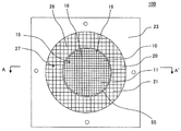
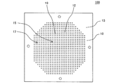
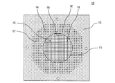
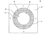
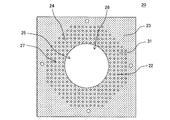
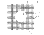
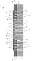
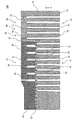
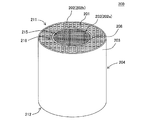
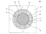
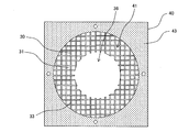
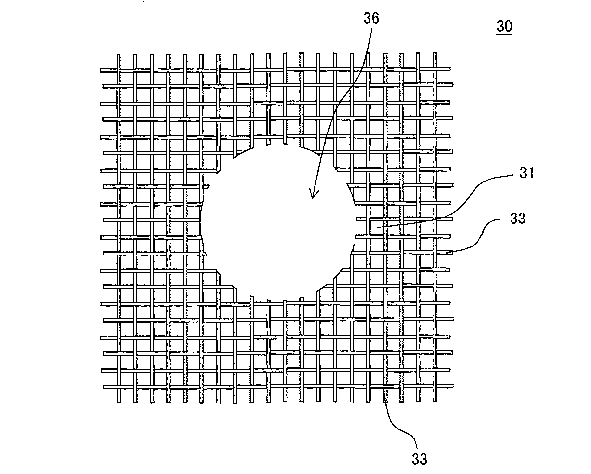
An embodiment of a die for forming a honeycomb structure of the present invention will be described. Here, FIG. 1 is a plan view schematically showing the clay discharge surface side of one embodiment of the die for forming a honeycomb structure of the present invention. FIG. 2 is a plan view of the honeycomb structure forming die shown in FIG. FIG. 3 is a plan view of the first base constituting the honeycomb structure forming die shown in FIG. Fig. 4 is a plan view of the second die constituting the honeycomb structure forming die shown in Fig. 1 on the side of the clay discharge surface. FIG. 5 is a plan view of the second die constituting the honeycomb structure forming die shown in FIG. FIG. 6 is a plan view of a mesh member constituting the die for forming a honeycomb structure shown in FIG. FIG. 7 is a cross-sectional view schematically showing an AA ′ cross section of the honeycomb structure forming die shown in FIG. 1. FIG. 8 is an enlarged cross-sectional view in which a part of FIG. 7 is enlarged. In FIGS. 3, 5, and 6, the surfaces of the first base, the second base, and the mesh member are indicated by hatching.
図1〜図8に示すように、本実施形態のハニカム構造体成形用口金100は、第一口金10と、第二口金20と、網状部材30と、を備えたものである。第一口金10は、成形原料としての坏土の押出方向Xの上流側に配置され、坏土排出面18側の中央部15が押出方向の下流側に向かって突出した凸部16を有する。第二口金20は、第一口金10の下流側に配置され、第一口金10の凸部16と相補的な形状を呈する環状の口金である。網状部材30は、第一口金10と第二口金20の間に配設されたものである。網状部材30は、第一口金10の外周部17における下流側の面(下流面14)と、第二口金20の上流側の面(上流面24)との間に空間を形成するためのスペーサー(spacer)として機能する。以下、本実施形態のハニカム構造体成形用口金100を、単に、「口金100」ということがある。坏土の押出方向Xとは、本実施形態の口金100を用いて押出成形する際の押出方向のことであり、坏土導入面19から坏土排出面18に向かう方向のことである。
As shown in FIGS. 1 to 8, the honeycomb structure forming die 100 of this embodiment includes a
本実施形態の口金100において、第一口金10の中央部15には、第一坏土導入孔12と、当該第一坏土導入孔12に連通した格子状の第一スリット11とが形成されている。第一坏土導入孔12は、格子状の第一スリット11の交点と押出方向Xに対して同軸上に形成されている。即ち、第一坏土導入孔12は、格子状の第一スリット11の交点に連通している。また、第一口金10の中央部15を取り囲む外周部17には、当該第一口金10の外周部17を貫通するように第一坏土導入孔12が形成されている。
In the
環状の第二口金20には、第一口金10の外周部17に形成された第一坏土導入孔12から排出された坏土が導入される第二坏土導入孔22と、当該第二坏土導入孔22に連通した格子状の第二スリット21とが形成されている。第二坏土導入孔22は、格子状の第二スリット21の交点と押出方向Xに対して同軸上に形成されている。即ち、第二坏土導入孔22は、格子状の第二スリット21の交点に連通している。また、本実施形態の口金100においては、第一口金10の外周部17の第一坏土導入孔12の開口位置と、第二口金20の第二坏土導入孔22の開口位置とが、少なくとも一部において一致しないように構成されている。
In the annular
本実施形態の口金100においては、第一口金10と第二口金20とで、網状部材30を挟持するようにして組み合わされている。以下、第一口金10の外周部17の押出方向Xの下流側の端面を、「第一口金10の外周部17における下流面14」といい、環状の第二口金20の押出方向Xの上流側の端面を、「第二口金20の上流面24」ということがある。また、以下、単に、上流側という場合は、押出方向Xの上流側を意味し、単に、下流側という場合は、押出方向Xの下流側を意味する。
In the
本実施形態の口金100は、第一口金10の外周部17における下流面14と、第二口金20の上流面24との間に、第一坏土導入孔12と第二坏土導入孔22との相互間に、網状部材30の網目によって形成された、坏土が移動するための流路31を有する。図6〜図8において、符号33は、網状部材30を構成する線材33を示す。図6に示すように、網状部材30の中央部分には、第一口金10の凸部16に該当する部分が円形にくり抜かれた空隙部36を有する。
The
本実施形態の口金100は、第一口金10の凸部16の外周面と、環状の第二口金20の内周面との間に、坏土を環状に押出成形するための隙間部55を有する。即ち、本実施形態の口金100においては、第二口金20の中央部25における空隙部26が、第一口金10の凸部16の周縁よりも若干大きく形成されている。このように構成することにより、第一口金10の凸部16を、環状の第二口金20の空隙部26に挿入するように組み合わせた際に、第一口金10の凸部16と第二口金20との間に、環状の隙間部55が形成される。この環状の隙間部55が、ハニカム成形体の境界壁を成形するための隙間部55となる。本発明において、「第一口金10の凸部16と相補的な形状を呈する環状の第二口金20」とは、第一口金10の凸部16より若干大きな空隙部26を有する環状の口金ことを意味する。
The
本実施形態の口金100においては、第一口金10の押出方向Xの上流側の端面が、口金100全体の坏土導入面19となっている。したがって、押出成形時においては、まず、成形原料としての坏土が、第一口金10の坏土導入面19に開口した第一坏土導入孔12に導入される。第一口金10の中央部15の第一坏土導入孔12に導入された坏土は、第一坏土導入孔12に連通した格子状の第一スリット11へと移動し、第一口金の坏土排出面18から、第一スリット11の形状に対応した成形体として排出される。一方、第一口金10の外周部17の第一坏土導入孔12に導入された坏土は、第一口金10の下流面14側から排出され、網状部材30の網目を経由して、第二口金20の第二坏土導入孔22に導入される。このため、第一口金10の第一坏土導入孔12と、第二口金20の第二坏土導入孔22との位置が一致していなくとも、第一坏土導入孔12と第二坏土導入孔22との相互間で坏土の移動が良好に行われる。網状部材30は、例えば、横方向に延びる線材33と、縦方向に延びる線材33とを編み合わせて形成されたものであるため、編み合わせた線材33が重なる部分以外では、網状部材30の網目間においても坏土の移動が行われる。このため、網状部材30の網目を経由して坏土の移動が行われる際に、第二坏土導入孔22に導入される坏土の流量分布を均等化することができる。第二口金20の第二坏土導入孔22に導入された坏土は、第二坏土導入孔22に連通した格子状の第二スリット21へと移動し、第二口金の坏土排出面28から、第二スリット21の形状に対応した成形体として排出される。したがって、本実施形態の口金100によれば、第二口金20の第二スリット21からの坏土の排出量が均等化され、ハニカム成形体を高品質に成形することができる。また、網状部材30の網目によって形成された流路31は、坏土を環状に押出成形するための隙間部55にも連通しているため、第一口金10の外周部17の第一坏土導入孔12に導入された坏土は、網状部材30の網目を経由して、隙間部55にも導入される。したがって、隙間部55に導入される坏土の流量分布も均等化することができ、押出成形されるハニカム成形体の境界壁周辺での成形不良の発生についても特に有効に抑制することができる。このため、本実施形態の口金100は、中央部と外周部とのセル構造が異なり、且つ中央部と外周部との境界に境界壁を有するハニカム成形体を、高品質に成形することができる。
In the
本明細書において、「セル構造」は、隔壁厚さ、セル密度、及びセル形状で規定されるハニカム構造体の構造のことを意味する。また、「スリットの形状」は、口金に形成されるスリットの幅、深さ、長さ、及びスリット相互の接続形態で規定されるスリットの形状のことを意味する。 In the present specification, the “cell structure” means a structure of a honeycomb structure defined by partition wall thickness, cell density, and cell shape. Further, the “slit shape” means the shape of the slit defined by the width, depth, length of the slit formed in the die and the connection form of the slits.
また、第一口金10と第二口金20との間に網状部材30を配設せずに、第一口金10と第二口金20との間に空間を設けようとすると、第二口金20が片持ち梁のような状態となってしまう。このように、第二口金20が片持ち梁のような状態となってしまうと、口金交換時やラム成形停止時において、口金100に背圧が生じた際に、第二口金20が変形してしまうことがある。本実施形態の口金100は、第一口金10と第二口金20との間に網状部材30が配設されているため、第二口金20に生じる背圧を網状部材30によって受け止め、当該背圧を分散させることができる。
Further, if a
更に、図示は省略するが、本実施形態の口金においては、第二スリットの形状が異なる数種類の第二口金を別途用意し、成形するハニカム成形体のセル構造に合わせて、第二口金を交換して使用することもできる。第二口金の第二坏土導入孔は、格子状の第二スリットの交点と押出方向に対して同軸上に形成されているため、第二口金の上流面における第二坏土導入孔の開口位置は、第二口金の第二スリットの形状によってそれぞれ異なることとなる。第二スリットの形状が異なる第二口金を使用した場合であっても、第一口金と第二口金との間に網状部材を配設することにより、口金内における坏土の移動が阻害されることがなく、中央部と外周部とで、常に均一な押出成形を実現することができる。 Further, although not shown, in the base of this embodiment, several types of second bases having different second slit shapes are separately prepared, and the second base is replaced in accordance with the cell structure of the honeycomb formed body to be formed. Can also be used. Since the second clay introduction hole of the second die is formed coaxially with the intersection of the grid-like second slit and the extrusion direction, the opening of the second clay introduction hole on the upstream surface of the second die The position differs depending on the shape of the second slit of the second base. Even when a second base having a different shape of the second slit is used, the movement of the clay in the base is hindered by disposing a mesh member between the first base and the second base. Therefore, it is possible to always achieve uniform extrusion molding between the central portion and the outer peripheral portion.
また、本実施形態の口金100においては、網状部材30が第一口金10及び第二口金20とは独立した別部材であるため、網状部材30を交換することで、網状部材30の厚さや、網目の大きさなどを簡便に変更することができる。例えば、網状部材30の押出方向Xの厚さを変更することで、第一口金10と第二口金20との押出方向Xの距離を調整することができる。そして、上記した押出方向Xの距離を調整することで、隙間部55に導入される坏土の量を調節することができる。例えば、図9に示すような網状部材30Aを用い、第一口金10と第二口金20と押出方向Xの距離を調節することができる。図9に示す網状部材30Aは、図8に示す網状部材30の線材33よりも、直径の大きな線材33Aを用いて形成された網状部材30Aである。ここで、図9は、図8に示すハニカム構造体成形用口金において、網状部材を交換した状態を示す拡大断面図である。図9に示す口金100において、図8に示す口金100と同様に構成された構成要素については、図8と同一の符号を付し、説明を省略することがある。図9において、符号31Aは、網状部材30Aの網目によって形成された流路を示す。
Further, in the
例えば、図8に示す口金100を使用する際に、成形原料としての坏土の種類を変更すると、坏土の流動性が変わり、隙間部55に導入される坏土の流量分布が変化することがある。このため、坏土の種類を変更した場合には、第二スリット21と隙間部55の坏土消費量のバランスが崩れることがある。また、第二口金20を、第二スリットの形状が異なる別の第二口金(図示せず)に交換した場合にも、第二口金20の第二スリット21から排出される坏土の量が変わり、第二スリット21と隙間部55の坏土消費量のバランスが崩れることがある。第二スリット21と隙間部55の坏土消費量のバランスが崩れてしまった場合には、網状部材30の厚さを調整し、隙間部55に導入される坏土の量を調節することで、ハニカム成形体の境界壁周辺における成形不良の発生を有効に抑制することができる。また、網状部材30の厚さを調整すること以外にも、例えば、網状部材30の網目の大きさを調整して、隙間部55に導入される坏土の量を調節することもできる。本実施形態の口金100は、坏土の種類の変更や、第二口金の変更などを行った場合においても、網状部材30の厚さや網目の大きさを調整することで、口金100内の坏土の流量分布を適切なものとすることできる。したがって、本実施形態の口金100は、単に、第二口金を変更可能にするという効果を奏するだけでなく、極めて汎用性に優れるという特段顕著な効果を奏するものである。
For example, when the base 100 shown in FIG. 8 is used, if the type of the clay as a forming raw material is changed, the fluidity of the clay changes, and the flow rate distribution of the clay introduced into the
ここで、本実施形態のハニカム構造体成形用口金によって作製されたハニカム構造体について説明する。図10は、本発明のハニカム構造体成形用口金によって作製されたハニカム構造体の一例を模式的に示す斜視図である。図11は、図10に示すハニカム構造体の流入端面を模式的に示す平面図である。図12は、図11のB−B’断面を示す模式的に示す断面図である。 Here, the honeycomb structure manufactured by the die for forming a honeycomb structure of the present embodiment will be described. FIG. 10 is a perspective view schematically showing an example of a honeycomb structure manufactured by the honeycomb structure forming die of the present invention. FIG. 11 is a plan view schematically showing the inflow end face of the honeycomb structure shown in FIG. 12 is a cross-sectional view schematically showing a B-B ′ cross section of FIG. 11.
図10〜図12に示すハニカム構造体200は、多孔質の隔壁201と、隔壁201の外周を囲繞するように配設された外周壁203と、を有する、柱状のハニカム構造部204を備えたものである。ハニカム構造部204の隔壁201は、流入端面211から流出端面212まで延びる流体の流路となる複数のセル202を区画形成するものである。そして、このハニカム構造部204は、中央セル構造215、外周セル構造216、及び外周セル構造216と中央セル構造215の境界部分に配設された境界壁208を有する。ハニカム構造部204において、中央セル構造215と、外周セル構造216とは、異なるセル構造である。
A
ここで、中央セル構造215とは、ハニカム構造部204のセル202の延びる方向に直交する面において、ハニカム構造部204の中央部分に形成された複数のセル202aによって構成されたセル構造のことである。外周セル構造216とは、上記面において、ハニカム構造部204の中央部分よりも外周寄りに形成された複数のセル202bによって構成されたセル構造のことである。
Here, the
「セル構造」とは、セル202の延びる方向に直交する面において、隔壁201によって区画されたセル202の1個、又は複数個のセル202の組み合わが、1つの繰り返し単位となり、その繰り返し単位の集合によって形成される構造のことをいう。例えば、同一形状のセルが、上記面において規則的に配列している場合、同一形状のセルの存在する範囲が、1つのセル構造となる。また、異なるセル形状のセルであっても、複数個のセルの組み合わせが1つの繰り返し単位となる場合には、その繰り返し単位が存在する範囲が、1つのセル構造となる。
The “cell structure” means that one of the
2つのセル構造が「異なるセル構造」であるとは、2つのセル構造を比較した場合に、隔壁厚さ、セル密度、セル形状のいずれか1つが異なることを意味する。ここで、「隔壁厚さが異なる」とは、2つのセル構造の隔壁厚さを比較した場合に、25μm以上の差を有することをいう。また、「セル密度が異なる」とは、2つのセル構造のセル密度を比較した場合に、7個/cm2以上の差を有することをいう。 The two cell structures being “different cell structures” means that any one of the partition wall thickness, cell density, and cell shape is different when the two cell structures are compared. Here, “different partition wall thicknesses” means having a difference of 25 μm or more when the partition wall thicknesses of two cell structures are compared. Further, “different cell densities” means having a difference of 7 cells / cm 2 or more when the cell densities of two cell structures are compared.
本実施形態の口金は、図10〜図12に示すようなハニカム構造体200を製造するためのハニカム成形体の成形に好適に用いることができる。以下、本実施形態の口金のより好適な形態について説明する。
The die of the present embodiment can be suitably used for forming a honeycomb formed body for manufacturing a
本実施形態の口金は、図1〜図8に示すように、第一スリット11の形状と、第二スリット21の形状とが異なるものであることが好ましい。第一スリット11の形状及び第二スリット21の形状については特に制限はなく、成形するハニカム成形体のセル構造に合わせて適宜選択することができる。また、第二スリット21の形状が異なる2種以上の第二口金20を備え、第二口金20を交換可能に構成されていてもよい。更に、第一スリット11の形状が異なる2種以上の第一口金10を備え、第一口金10を交換可能に構成されていてもよい。
As shown in FIGS. 1 to 8, the base of the present embodiment is preferably such that the shape of the
網状部材30は、複数本の線材33を編み合わせて形成された網状の部材を挙げることができる。ただし、網状部材30は、網目の交差する部位の厚さが厚く、この交差する部位に比して他の部位が相対的に薄くなるように構成された網目状のものであればよい。例えば、網状部材30としては、型成形等により、複数本の線材33が予め一体的に形成された網目状のものであってもよい。なお、網状部材の代用として、板状部材に対して複数の孔を穿孔した、パンチングプレート等の孔開き部材を用いることもできる。ただし、このような孔開き部材は、それぞれの孔が独立して形成された孔であるため、複数の孔の相互間での坏土の移動が困難となる。このため、パンチングプレート等の孔開き部材は、本実施形態の口金100の網状部材30に比して、坏土の流量分布を均等化するという効果が得られ難いものとなる。
The
網状部材30を構成する線材33の直径については特に制限はなく、例えば、0.030〜0.500mmであることが好ましい。線材33の直径が0.030mm未満であると、網状部材30の厚さが薄くなり過ぎて、坏土の流量分布の均等化がされ難くなることがある。また、線材33が細くなり、網状部材30の強度が低下することがある。線材33の直径が0.500mmを超えると、坏土導入孔に対して網目が大きくなりすぎることで、各導入穴で流速差が生じてしまい、成形性が悪化する点で好ましくない。なお、網状部材30の厚さは、概ね、上述した線材33の直径の2倍の値となる。
There is no restriction | limiting in particular about the diameter of the
網状部材30の網目の大きさについては特に制限はない。例えば、1cm当たりの網目の数は、3.9〜130個であることが好ましい。1cm当たりの網目の数が3.9個未満であると、網状部材30の強度が低下し、網状部材30が変形し易くなることがある。特に、線材33の直径が小さい場合には、網状部材30の変形がより顕著なものとなる。一方、1cm当たりの網目の数が130個を超えると、網状部材30の網目が密になり過ぎて、坏土が通過する際の抵抗が大きくなることがある。また、1cm当たりの網目の数が多くなるに従って、使用することができる線材33の直径に制限が生まれ、それに伴って、網状部材30の厚さの上限が制限されてしまう。
There is no particular limitation on the size of the mesh of the
本実施形態の口金100は、2つ以上の網状部材30を備えたものであってもよい。例えば、図8及び図9に示すような、厚さの異なる2つ以上の網状部材30,30Aが予め用意されたものであってもよい。そして、押出成形時の成形条件に応じて、2つ以上の網状部材30,30Aの中から、第一口金10と第二口金20と押出方向Xの距離が最適となるものを適宜選択して使用してもよい。また、図示は省略するが、2つ以上の網状部材は、1cm当たりの網目の数、別言すれば、網目の大きさが異なるものであってもよい。
The
押出成形するハニカム成形体の端面の面積に対する、第一口金10の中央部15の面積の割合については、成形するハニカム成形体の中央部及び外周部のセル構造(例えば、図10〜図12参照)に応じて適宜決定することができる。なお、本実施形態の口金においては、上記割合が、30〜70%であることが好ましく、40〜60%であることが特に好ましい。
Regarding the ratio of the area of the
上述したように、口金100においては、第二口金20の中央部25における空隙部26が、第一口金10の凸部16の周縁よりも若干大きく形成され、第一口金10の凸部16と第二口金20との間に、環状の隙間部55が形成されている。上述した環状の隙間部55の間隔については特に制限はなく、成形するハニカム成形体の境界壁の厚さに応じて適宜選択することができる。例えば、環状の隙間部55の間隔は、0.04〜0.50mmであることが好ましい。
As described above, in the
第一口金10は、中央部15と外周部17とで、第一坏土導入孔12の開口径、及びそれぞれの第一坏土導入孔12の相互間の間隔が同一であることが好ましい。このように構成することによって、例えば、第一口金10を簡便に且つ低コストに製造することができる。
As for the 1st nozzle | cap | die 10, it is preferable in the
また、本実施形態の口金は、第一スリットのうちの一つのセルを取り囲むスリットと、第二スリットのうちの一つのセルを取り囲むスリットとが、互いに交差する方向に延びるものであってもよい。ここで、「セル」とは、成形するハニカム成形体において、隔壁によって区画形成された空間を意味する。例えば、図13に示す口金300は、図1に示す口金100に対して、第一口金10の第一スリット11が時計回りに45°回転した状態となるように作製されている。このため、口金300においては、第一スリット11のうちの一つのセルを取り囲むスリットと、第二スリット21のうちの一つのセルを取り囲むスリットとが、平行な位置関係を有していない。本実施形態の口金は、上述したように、第一スリット及び第二スリットにおいて、各セルを取り囲むスリットが互いに交差するような場合でも、坏土の流量分布を均等化することができる。したがって、第二口金の第二スリットからの坏土の排出量が均等化され、ハニカム成形体を高品質に成形することができる。
The base of the present embodiment may extend in a direction in which a slit surrounding one cell of the first slit and a slit surrounding one cell of the second slit intersect each other. . Here, the “cell” means a space defined by partition walls in the honeycomb formed body to be formed. For example, the base 300 shown in FIG. 13 is manufactured such that the
本実施形態の口金100は、図1に示すように、第一スリット11によって押出されるハニカム成形体のセル構造の配列方向と、第二スリット21によって押出されるハニカム成形体のセル構造の配列方向とが、平行となっている。即ち、第一口金10の第一スリット11の延びる方向と、第二口金20の第二スリット21の延びる方向とが、平行となっている。但し、図13に示す口金300のように、第一スリット11によって押出されるハニカム成形体のセル構造の配列方向と、第二スリット21によって押出されるハニカム成形体のセル構造の配列方向とが、互いに交差する方向に延びるものであってもよい。図13は、本発明のハニカム構造体成形用口金の他の実施形態の坏土排出面側を模式的に示す平面図である。図13に示す口金300において、図1に示す口金100と同様の構成要素については、同一の符号を付して説明を省略することがある。
As shown in FIG. 1, the
図13に示す口金300においても、第一口金10と第二口金20の間に、網状部材30(図8参照)を備えている。このため、図13に示す口金300のように、第一口金10の第一スリット11の延びる方向と、第二口金20の第二スリット21の延びる方向とが、互いに交差するような場合でも、坏土の流量分布を均等化することができる。したがって、第二口金20の第二スリット21からの坏土の排出量が均等化され、ハニカム成形体を高品質に成形することができる。
Also in the base 300 shown in FIG. 13, a mesh member 30 (see FIG. 8) is provided between the
また、図13に示す口金300は、予め、第一口金10の第一スリット11が時計回りに45°回転した状態となるように作製されたものである。ただし、例えば、図1に示す口金100において、第一口金10を時計回りに45°回転させて使用することもできる。図1に示す口金100の第一口金10を時計回りに45°回転させた場合でも、図7及び図8に示すように、第一口金10と第二口金20の間には網状部材30が存在するため、口金100内における坏土の移動が阻害されることはない。網状部材30を備えていない従来の口金は、例えば、第一口金の第一坏土導入孔と、第二口金の第二坏土導入孔とが、坏土の押出方向において一致するように設計されている。このため、第一口金のみを回転させて使用した場合には、口金内における坏土の移動が阻害されてしまう。
A base 300 shown in FIG. 13 is manufactured in advance so that the
図1〜図8に示すような本実施形態の口金において、第一口金10の厚さ、第一口金10の凸部16の突出高さ、及び第二口金20の厚さについては特に制限はない。第一口金10の厚さとしては、10〜50mmであることが好ましい。第一口金10の凸部16の突出高さとしては、10〜30mmであることが好ましい。第二口金20の厚さとしては、10〜30mmであることが好ましい。なお、第一口金10の凸部16の突出高さと、第二口金20の厚さとは、同じであってもよいし、異なっていてもよい。例えば、環状の第二口金20の空隙部26内に、第一口金10の凸部16を挿入した際に、第一口金10の坏土排出面18の位置と、第二口金20の坏土排出面28の位置とが、一致していてもよいし、一致していなくともよい。
In the base of the present embodiment as shown in FIGS. 1 to 8, the thickness of the
また、本発明の口金は、図14に示すような、環状の空間確保用部材40を更に備えたものであってもよい。ここで、図14は、本発明のハニカム構造体成形用口金の更に他の実施形態に用いられる網状部材及び空間確保用部材を模式的に示す平面図である。空間確保用部材40は、基材43の中央部分が円形にくり抜かれることによって、空間確保用部材40の中央部分に空間41が形成されている。空間確保用部材40は、第一口金10(図8参照)と第二口金20(図8参照)の間に配設されて使用される。したがって、空間確保用部材40は、第一口金の外周部における下流側の面(下流面)と第二口金の上流側の面(上流面)との間に空間を形成するためのスペーサー(spacer)として機能する。空間確保用部材40の内側部分、即ち、基材43に形成された空間41には、これまに説明したような網状部材30が配設されていることが好ましい。図14に示す網状部材30は、例えば、図6に示す網状部材30の外周部分を円形としたドーナツ状のものである。図14においては、ドーナツ状の網状部材30が、空間確保用部材40の空間41内に収納されており、網状部材30と空間確保用部材40との双方が、第一口金10(図8参照)と第二口金20(図8参照)の間に配設されている。
The base of the present invention may further include an annular space securing member 40 as shown in FIG. Here, FIG. 14 is a plan view schematically showing a net-like member and a space securing member used in still another embodiment of the honeycomb structure forming die of the present invention. The space securing member 40 has a
図14に示すような空間確保用部材40を更に備えることにより、押出成形時において、網状部材30に加わる圧縮応力を緩和することでき、網状部材30の変形や破損を有効に抑制することができる。図14に示す網状部材30は、図6に示す網状部材30の外周部分が円形となったドーナツ状であること以外は、図6に示す網状部材30と同様に構成されていることが好ましい。図14に示す網状部材30において、図6に示す網状部材30と同様の構成要素については、同一の符号を付し説明を省略する。
By further providing a space securing member 40 as shown in FIG. 14, the compressive stress applied to the
第一口金10を構成する第一口金基材13、及び第二口金20を構成する第二口金基材23の材料としては、ハニカム構造体成形用の口金の材料として一般的に用いられている金属又は合金を挙げることができる。以下、第一口金基材及び第二口金基材を総称して、単に「口金基材」ということがある。例えば、口金基材の材料として、鉄(Fe)、チタン(Ti)、ニッケル(Ni)、銅(Cu)、及びアルミニウム(Al)から構成される群より選ばれる少なくとも一つの金属を含む金属又は合金を挙げることができる。
As the material of the
口金基材の材料として使用される合金の一例として、ステンレス合金、より具体的には、SUS630を挙げることができる。このようなステンレス合金は、加工が比較的に容易であるとともに、安価な材料である。また、口金基材を構成する合金の他例として、耐摩耗性に優れた炭化タングステン基超硬合金等を挙げることができる。炭化タングステン基超硬合金等によって構成された口金基材を用いることにより、スリットの磨耗が少ないハニカム構造体成形用口金を製造することができる。 As an example of the alloy used as the material of the die base material, a stainless alloy, more specifically, SUS630 can be given. Such a stainless alloy is an inexpensive material that is relatively easy to process. Further, other examples of the alloy constituting the die base material include a tungsten carbide base cemented carbide having excellent wear resistance. By using a base material made of a tungsten carbide base cemented carbide or the like, a die for forming a honeycomb structure with less wear of the slit can be manufactured.
網状部材30の材料としては、特に限定されることはないが、例えば、各種の金属又は合金を挙げることができる。
The material of the
本実施形態の口金を製造する方法については特に制限はない。例えば、本実施形態の口金は、従来公知の口金の製造方法に準じて製造することができる。 There is no restriction | limiting in particular about the method of manufacturing the nozzle | cap | die of this embodiment. For example, the base of the present embodiment can be manufactured according to a conventionally known base manufacturing method.
第一坏土導入孔及び第二坏土導入孔については、第一口金基材及び第二口金基材に対して、ドリル加工、放電加工、電解加工、及びレーザー加工等の公知の機械加工を用いて形成することができる。 For the first clay introduction hole and the second clay introduction hole, known machining such as drilling, electric discharge machining, electrolytic machining, and laser machining is used for the first die base material and the second die base material. Can be formed.
第一スリット及び第二スリットについては、第一口金基材及び第二口金基材に対して、研削加工、放電加工、電解加工、レーザー加工等の公知の機械加工を用いて形成することができる。 About a 1st slit base and a 2nd slit, it can form using well-known machining processes, such as grinding, electrical discharge machining, electrolytic processing, and laser processing, with respect to a 1st base material and a 2nd base material.
第一口金の中央部を構成する凸部は、研削加工、放電加工、あるいは二部材の接合によって形成することができる。 The convex part which comprises the center part of a 1st nozzle | cap | die can be formed by grinding, electric discharge machining, or joining of 2 members.
網状部材は、例えば、複数の線材を編み合わせて作製された金網を用意し、用意した金網の中央部分に、第一口金の凸部に相当する大きさの孔を穿孔することによって製造することができる。 The mesh member is manufactured, for example, by preparing a wire mesh produced by knitting a plurality of wire rods, and drilling a hole having a size corresponding to the convex portion of the first die in the central portion of the prepared wire mesh. be able to.
以下、本発明を実施例によって更に具体的に説明するが、本発明はこれらの実施例によって何ら限定されるものではない。 EXAMPLES Hereinafter, the present invention will be described more specifically with reference to examples, but the present invention is not limited to these examples.
(実施例1)
実施例1では、図10〜図12に示すようなハニカム構造部204の中央セル構造215と外周セル構造216とが異なるセル構造のハニカム構造体200を作製するための口金を製造した。より具体的には、実施例1では、最終製品としてのハニカム構造体が、以下のように構成されたハニカム構造体となるような口金を作製した。最終製品としてのハニカム構造体は、端面の直径が100mmの円柱状であり、当該端面における中央セル構造の直径が70mmである。中央セル構造と外周セル構造の境界には、厚さ0.1mmの境界壁を有する。中央セル構造は、セルの形状が四角形で、隔壁厚さが0.09mm、セル密度が93個/cm2である。外周セル構造は、セルの形状が四角形で、隔壁厚さが0.11mm、セル密度が62個/cm2である。なお、上記のハニカム構造体に各寸法については、製造公差を含んでいない。
Example 1
In Example 1, a die for manufacturing a
まず、実施例1では、縦200mm、横200mm、厚さ20mmの板状の第一口金基材を用意した。口金基材は、ステンレス製のものとした。用意した第一口金基材の一方の表面を坏土排出面とし、その坏土排出面側の中央部分に、放電加工により、突出長が10mmとなるよう凸部を形成した。 First, in Example 1, a plate-shaped first die base material having a length of 200 mm, a width of 200 mm, and a thickness of 20 mm was prepared. The base material for the base was made of stainless steel. One surface of the prepared first die base material was used as a clay discharge surface, and a convex portion was formed in the central portion on the clay discharge surface side by an electric discharge machining so that the protrusion length was 10 mm.
次に、第一口金基材の凸部の坏土排出面に、格子状の第一スリットを形成した。格子状の第一スリットは、上述した最終製品としてのハニカム構造体の中央セル構造を構成する隔壁を押出成形可能なスリット形状とした。第一スリットの形成は、研削加工によって行った。 Next, a grid-like first slit was formed on the clay discharge surface of the convex portion of the first die base. The lattice-shaped first slit was formed into a slit shape capable of extruding the partition walls constituting the central cell structure of the honeycomb structure as the final product described above. The first slit was formed by grinding.
次に、第一口金基材の坏土導入面に、第一スリットの交点部分に連通するように、開口径が1.2mmの第一坏土導入孔を形成した。また、第一口金基材については、凸部を有していない外周部についても、凸部を有する中央部と同一のピッチで第一坏土導入孔を形成した。第一口金基材の外周部の第一坏土導入孔は、第一口金基材の坏土導入面から、当該外周部の下流面まで連通する貫通孔とした。以上のようにして、実施例1の口金における第一口金を作製した。 Next, a first clay introduction hole having an opening diameter of 1.2 mm was formed on the clay introduction surface of the first die base so as to communicate with the intersection of the first slits. Moreover, about the 1st nozzle | cap | die base material, the 1st clay introduction hole was formed with the same pitch as the center part which has a convex part also about the outer peripheral part which does not have a convex part. The first clay introduction hole in the outer peripheral portion of the first base material was a through hole that communicated from the clay introduction surface of the first base material to the downstream surface of the outer periphery. As described above, the first die in the die of Example 1 was produced.
次に、縦200mm、横200mm、厚さ10mmの板状の第二口金基材を用意した。口金基材は、ステンレス製のものとした。用意した第二口金基材の中央部分を、円形状にくり抜いて、第二口金基材を環状のものとした。 Next, a plate-shaped second die base material having a length of 200 mm, a width of 200 mm, and a thickness of 10 mm was prepared. The base material for the base was made of stainless steel. The central portion of the prepared second base material was cut into a circular shape, so that the second base material was annular.
次に、第二口金基材の凸部の坏土排出面に、格子状の第二スリットを形成した。格子状の第二スリットは、上述した最終製品としてのハニカム構造体の外周セル構造を構成する隔壁を押出成形可能なスリット形状とした。第二スリットの形成は、研削加工によって行った。 Next, a grid-like second slit was formed on the clay discharge surface of the convex portion of the second die base material. The grid-like second slit was formed into a slit shape capable of extruding the partition walls constituting the peripheral cell structure of the honeycomb structure as the final product described above. The formation of the second slit was performed by grinding.
次に、第二口金基材の坏土排出面とは反対側の面に、第二スリットの交点部分に連通するように、開口径が1.2mmの第二坏土導入孔を形成した。 Next, a second clay introduction hole having an opening diameter of 1.2 mm was formed on the surface of the second die base material opposite to the clay discharge surface so as to communicate with the intersection of the second slits.
次に、直径が0.2mmの線材が、1cm当たりの網目の数が7個となるように編み合わせて作製された金網を用意した。この金網は、ステンレス製のものとした。用意した金網の中央部分を、直径80mmの円形状にくり抜いて、第一口金の中央部に相当する部分に空間を有する網状部材を作製した。 Next, a wire net produced by knitting a wire rod having a diameter of 0.2 mm so that the number of meshes per cm was 7 was prepared. This wire mesh was made of stainless steel. A central portion of the prepared wire mesh was cut into a circular shape having a diameter of 80 mm, and a mesh member having a space in a portion corresponding to the central portion of the first base was produced.
次に、第一口金の外周部よりも外側の坏土排出面側に網状部材を配置した状態で、第二口金の中央部の空隙部に、第一口金の中央部の凸部を挿入するようにして、第一口金と第二口金によって網状部材を挟持するように、実施例1の口金を製造した。 Next, in a state where the mesh member is arranged on the clay discharge surface side outside the outer peripheral part of the first base, the convex part of the central part of the first base is formed in the gap part of the central part of the second base. The base of Example 1 was manufactured such that the mesh member was sandwiched between the first base and the second base as inserted.
表1に、「口金構造」、「第二スリットのピッチ(mm)」、及び「境界部成形用の隙間部の間隔(mm)」を示す。また、表1に、網状部材の「有無」、網状部材を構成する「線材の直径(mm)」、及び網状部材の「1cm当たりの網目の数(個)」を示す。なお、実施例1の口金のように、第一口金と第二口金によって網状部材を挟持するように組み合せて1つの口金を製造したものについて、「口金構造」の欄において「二体組付」と記す。一方、1つの口金基材に対して、中央部と外周部とでスリットの形状が異なるようにして製造した口金について、「口金構造」の欄において「一体構造」と記す。 Table 1 shows “the base structure”, “the pitch of the second slit (mm)”, and “the interval between the gaps for forming the boundary part (mm)”. Table 1 shows the “presence / absence” of the mesh member, the “diameter (mm) of wire” constituting the mesh member, and the “number of meshes per 1 cm” of the mesh member. In addition, in the “base structure” column, the “two-body assembly” is used for manufacturing one base by combining the first base and the second base so that the net-like member is sandwiched as in the base of Example 1. ". On the other hand, a base manufactured by making the slit shape different between the central portion and the outer peripheral portion with respect to one base material is referred to as “integrated structure” in the “base structure” column.
実施例1の口金の製造に要した総作業時間は、70時間であった。実施例1の口金を用いて、以下に示すような方法で、「成形品品質」、及び「第二口金の変形の有無」の評価を行った。結果を表1に示す。 The total work time required for manufacturing the die of Example 1 was 70 hours. Using the die of Example 1, “molded product quality” and “presence / absence of deformation of the second die” were evaluated by the following methods. The results are shown in Table 1.
[成形品品質]
作製した口金を用いて、コージェライト組成から成るハニカム構造体を押出成形した。押出成形したハニカム構造体を目視で確認し、ハニカム構造体の品質を以下の評価基準で評価した。外観不良なき場合を「良」とする。外観不良ある場合、又は成形不可である場合を「不可」とする。ここで、「外観不良」とは口金各部における押出速度ばらつきにより、ハニカム構造体を構成する隔壁が湾曲することを指す。
[Molded product quality]
A honeycomb structure having a cordierite composition was extruded using the produced die. The extruded honeycomb structure was visually confirmed, and the quality of the honeycomb structure was evaluated according to the following evaluation criteria. A case where there is no appearance defect is defined as “good”. The case where the appearance is poor or the case where molding is impossible is defined as “impossible”. Here, “exterior appearance” means that the partition walls constituting the honeycomb structure are curved due to variations in extrusion speed at each part of the die.
[第二口金の変形の有無]
作製した口金を用いて、成形品品質の評価と同条件の押出成形を3回行い、押出成形が終了した段階で、第二口金の変形の有無を目視で確認した。第二口金に変形が確認された場合を「有り」とし、第二口金に変形が確認されなかった場合を「無し」とする。
[The presence or absence of deformation of the second cap]
Using the produced die, extrusion molding under the same conditions as the evaluation of the molded product quality was performed three times, and when the extrusion molding was completed, the presence or absence of deformation of the second die was visually confirmed. The case where deformation is confirmed in the second base is “present”, and the case where deformation is not confirmed in the second base is “not present”.
(実施例2,3)
網状部材の「線材の直径(mm)」、及び「1cm当たりの網目の数(個)」を表1に示すような値となるように変更した以外は、実施例1と同様の方法で口金を製造した。実施例2,3の口金を用いて、実施例1と同様の方法で、「成形品品質」、及び「第二口金の変形の有無」の評価を行った。結果を表1に示す。
(Examples 2 and 3)
In the same manner as in Example 1, except that the “wire diameter (mm)” and “number of meshes per 1 cm (pieces)” of the mesh member were changed to values as shown in Table 1. Manufactured. Using the caps of Examples 2 and 3, evaluation of “molded product quality” and “presence / absence of deformation of second cap” was performed in the same manner as in Example 1. The results are shown in Table 1.
(比較例1)
比較例1では、縦200mm、横200mm、厚さ20mmの板状の口金基材を用意した。口金基材は、ステンレス製のものとした。用意した口金基材の一方の表面を坏土排出面とし、その坏土排出面側の中央部分に、実施例1の口金の第一スリットと同形状のスリットを形成した。次に、口金基材の坏土排出面側の外周部分に、実施例1の口金の第二スリットと同形状のスリットを形成した。次いで、実施例1の隙間部に相当する位置に第一スリットと第二スリットの端部を繋ぎ合せる環状のスリットを形成した。次に、口金基材の坏土導入面側から、各スリットの交点部分に連通するように、開口径が1.2mmの坏土導入孔を形成した。以上のようにして、比較例1の口金を製造した。
(Comparative Example 1)
In Comparative Example 1, a plate-shaped die base material having a length of 200 mm, a width of 200 mm, and a thickness of 20 mm was prepared. The base material for the base was made of stainless steel. One surface of the prepared base material was used as a clay discharge surface, and a slit having the same shape as the first slit of the base of Example 1 was formed in the central portion on the clay discharge surface side. Next, a slit having the same shape as the second slit of the base of Example 1 was formed on the outer peripheral portion of the base material on the clay discharge surface side. Next, an annular slit was formed at the position corresponding to the gap in Example 1 to join the ends of the first slit and the second slit. Next, a clay introduction hole having an opening diameter of 1.2 mm was formed so as to communicate with the intersection portion of each slit from the clay introduction surface side of the base material. The die of Comparative Example 1 was manufactured as described above.
比較例1の口金の製造に要した総作業時間は、100時間であった。比較例1の口金を用いて、実施例1と同様の方法で、「成形品品質」、及び「第二口金の変形の有無」の評価を行った。結果を表1に示す。 The total work time required for manufacturing the base of Comparative Example 1 was 100 hours. Using the die of Comparative Example 1, “molded product quality” and “presence / absence of deformation of second die” were evaluated in the same manner as in Example 1. The results are shown in Table 1.
(比較例2)
比較例2では、まず、実施例1の口金の第一口金及び第二口金と同様に構成された第一口金及び第二口金を作製した。次に、比較例2では、作製した第二口金の中央部の空隙部に、第一口金の中央部の凸部を挿入するようにして、第二口金と第一口金とを組み合わせ、比較例2の口金を製造した。即ち、比較例2では、第一口金と第二口金の間に網状部材を配置せずに口金を作製した。
(Comparative Example 2)
In Comparative Example 2, first and second caps that were configured in the same manner as the first and second caps of the cap of Example 1 were prepared. Next, in Comparative Example 2, the convex portion of the central portion of the first base is inserted into the gap portion of the central portion of the manufactured second base, and the second base and the first base are combined. The base of Comparative Example 2 was manufactured. That is, in Comparative Example 2, the die was manufactured without arranging the mesh member between the first die and the second die.
比較例2の口金の製造に要した総作業時間は、70時間であった。比較例2の口金を用いて、実施例1と同様の方法で、「成形品品質」、及び「第二口金の変形の有無」の評価を行った。結果を表1に示す。 The total work time required for manufacturing the base of Comparative Example 2 was 70 hours. Using the die of Comparative Example 2, “molded product quality” and “presence / absence of deformation of second die” were evaluated in the same manner as in Example 1. The results are shown in Table 1.
(比較例3)
比較例3では、まず、実施例1の口金の第一口金と同様に構成された第一口金を作製した。次に、比較例3では、第二口金基材の上流面から押出方向の0.1mmの範囲を研削加工によって取り除いた第二口金を作製した。このような第二口金の中央部の空隙部に、第一口金の中央部の凸部を挿入するようにして、第二口金と第一口金とを組み合わせ、比較例3の口金を製造した。比較例3の口金は、第一口金の外周部の下流面と第二口金の上流面とが当接せず、第二口金が片持ち梁のような状態で第一口金と組み合わされたものであった。
(Comparative Example 3)
In Comparative Example 3, first, a first base configured similarly to the first base of the base of Example 1 was produced. Next, in Comparative Example 3, a second die was prepared by removing a range of 0.1 mm in the extrusion direction from the upstream surface of the second die base material by grinding. The base part of Comparative Example 3 is manufactured by combining the second base part and the first base part so that the convex part of the central part of the first base part is inserted into the gap part of the central part of the second base part. did. The base of Comparative Example 3 is combined with the first base in a state where the downstream face of the outer periphery of the first base and the upstream face of the second base are not in contact with each other and the second base is like a cantilever. It was.
比較例3の口金の製造に要した総作業時間は、80時間であった。比較例3の口金を用いて、実施例1と同様の方法で、「成形品品質」、及び「第二口金の変形の有無」の評価を行った。結果を表1に示す。 The total work time required for manufacturing the base of Comparative Example 3 was 80 hours. Using the die of Comparative Example 3, “molded product quality” and “presence / absence of deformation of second die” were evaluated in the same manner as in Example 1. The results are shown in Table 1.
(結果)
実施例1〜3の口金は、比較例1の口金に比して製造時間を短縮することができるとともに、成形品品質の評価も良好なものであった。また、実施例1〜3の口金は、第二口金の変形も確認されなかった。
(result)
The bases of Examples 1 to 3 were able to shorten the manufacturing time as compared with the base of Comparative Example 1, and the evaluation of the quality of the molded product was also good. Moreover, the deformation | transformation of the 2nd nozzle | cap | die was not confirmed for the nozzle | cap | die of Examples 1-3.
比較例1の口金は、成形品品質の評価において、不可という結果となった。その理由としては、口金の中央部と外周部とでスリットの形状が異なっていると、口金内の坏土の流量分布が不均一になり易く、スリットからの坏土の排出量が均等にならないためと推測される。特に、比較例1の口金を用いて押出成形を行った場合には、境界壁を形成するための坏土の供給が追い付かず、境界壁及びその近傍において成形不良が多く確認された。 The base of Comparative Example 1 was not possible in the evaluation of the quality of the molded product. The reason for this is that if the shape of the slit is different between the central part and the outer peripheral part of the base, the distribution of the flow rate of the clay in the base is likely to be uneven, and the discharge amount of the clay from the slit is not uniform. It is presumed that. In particular, when extrusion molding was performed using the die of Comparative Example 1, the supply of clay for forming the boundary wall did not catch up, and many molding defects were confirmed at the boundary wall and its vicinity.
比較例2の口金は、第一口金の第一坏土導入孔と、第二口金の第二坏土導入孔との位置が一致していない箇所において、坏土の移動が阻害されており、成形品品質の評価において、不可という結果となった。また、比較例2の口金を用いて押出成形を行った場合には、境界壁を形成するための坏土の供給が追い付かず、境界壁及びその近傍においても成形不良が著しく確認された。 In the base of Comparative Example 2, the movement of the clay is obstructed at a location where the positions of the first clay introduction hole of the first die and the second clay introduction hole of the second die do not match. In the evaluation of the quality of the molded product, it was impossible. Moreover, when extrusion molding was performed using the die of Comparative Example 2, the supply of the clay for forming the boundary wall could not catch up, and a molding defect was remarkably confirmed at the boundary wall and its vicinity.
比較例3の口金は、成形品品質の評価は良好なものであったが、第二口金の変形の有無の評価において、第二口金の変形が確認された。第二口金の変形が顕著になると、成形品品質への影響が生じることがある。また、第二口金の変形が生じ易いものであると、口金の交換等に伴い、製品の製造コストが増大することが懸念される。 The base of Comparative Example 3 was good in evaluation of the quality of the molded product, but deformation of the second base was confirmed in the evaluation of the presence or absence of deformation of the second base. If the deformation of the second die becomes prominent, the quality of the molded product may be affected. Further, if the deformation of the second base is likely to occur, there is a concern that the manufacturing cost of the product increases with the replacement of the base.
本発明のハニカム構造体成形用口金は、中央部と外周部とのセル構造が異なるハニカム成形体の製造に利用することができる。 The die for forming a honeycomb structure of the present invention can be used for manufacturing a honeycomb formed body in which the cell structure is different between the central portion and the outer peripheral portion.
10:第一口金、11:第一スリット、12:第一坏土導入孔、13:第一口金基材、14:下流面(第一口金の外周部の下流面)、15:中央部、16:凸部、17:外周部、18:坏土排出面(第一口金の坏土排出面)、19:坏土導入面、20:第二口金、21:第二スリット、22:第二坏土導入孔、23:第二口金基材、24:上流面(第二口金の上流面)、25:中央部、26:空隙部、27:外周部、28:坏土排出面(第二口金の坏土排出面)、30,30A:網状部材、31,31A:流路、33,33A:線材、36:空隙部、40:空間確保用部材、41:空間、43:基材、55:隙間部(境界壁成形用の隙間部)、100,300:ハニカム構造体成形用口金(口金)、201:隔壁、202:セル、202a:セル(中央セル構造のセル)、202b:セル(外周セル構造のセル)、203:外周壁、204:ハニカム構造部、208:境界壁、211:流入端面、212:流出端面、215:中央セル構造、216:外周セル構造、200:ハニカム構造体、X:押出方向。 10: first base, 11: first slit, 12: first clay introduction hole, 13: first base material, 14: downstream surface (downstream surface of the outer periphery of the first base), 15: center portion , 16: convex part, 17: outer peripheral part, 18: clay discharge surface (soil discharge surface of the first base), 19: clay introduction surface, 20: second base, 21: second slit, 22: Second clay introduction hole, 23: second base material, 24: upstream surface (upstream surface of the second base), 25: central portion, 26: gap portion, 27: outer peripheral portion, 28: clay discharge surface ( (Soil discharge surface of second cap), 30, 30A: mesh member, 31, 31A: flow path, 33, 33A: wire rod, 36: gap portion, 40: space securing member, 41: space, 43: base material 55: Crevice part (gap part for forming boundary wall), 100, 300: Die for forming honeycomb structure (die), 201: partition wall, 202: cell, 202a: 202 (cell of central cell structure), 202b: cell (cell of outer peripheral cell structure), 203: outer peripheral wall, 204: honeycomb structure, 208: boundary wall, 211: inflow end surface, 212: outflow end surface, 215: central cell Structure: 216: peripheral cell structure, 200: honeycomb structure, X: extrusion direction.
Claims (11)
前記第一口金の下流側に配置され、前記凸部と相補的な形状を呈する環状の第二口金と、を備え、
前記第一口金の前記中央部には、第一坏土導入孔と、当該第一坏土導入孔に連通した格子状の第一スリットとが形成され、
前記第一口金の前記中央部を取り囲む外周部には、当該第一口金の前記外周部を貫通するように前記第一坏土導入孔が形成され、
環状の前記第二口金には、前記第一口金の前記外周部に形成された前記第一坏土導入孔から排出された前記坏土が導入される第二坏土導入孔と、当該第二坏土導入孔に連通した格子状の第二スリットとが形成され、且つ、
前記第一口金の凸部の外周面と環状の前記第二口金の内周面との間に、前記坏土を環状に押出成形するための隙間部を有し、
前記第一口金と前記第二口金の間に配設された網状部材を更に備え、前記網状部材の網目を経由して、前記第一坏土導入孔と前記第二坏土導入孔との相互間で前記坏土の移動が行われるように構成されているハニカム構造体成形用口金。 A first die having a convex portion that is disposed upstream of the extrusion direction of the clay as a forming raw material, and a central portion of the clay discharge surface side protrudes toward the downstream side of the extrusion direction;
An annular second base disposed on the downstream side of the first base and having a shape complementary to the convex portion;
In the central portion of the first base, a first clay introduction hole and a lattice-shaped first slit communicating with the first clay introduction hole are formed,
In the outer peripheral portion surrounding the central portion of the first base, the first clay introduction hole is formed so as to penetrate the outer peripheral portion of the first base,
In the annular second base, a second clay introduction hole into which the clay discharged from the first clay introduction hole formed in the outer peripheral portion of the first base is introduced, and the first A grid-like second slit communicated with the double clay introduction hole, and
Between the outer peripheral surface of the convex portion of the first base and the inner peripheral surface of the annular second base, there is a gap portion for extruding the clay in an annular shape,
A net member disposed between the first base and the second base; and through the mesh of the net member, the first clay introduction hole and the second clay introduction hole A die for forming a honeycomb structure configured to move the clay between each other.
Priority Applications (3)
| Application Number | Priority Date | Filing Date | Title |
|---|---|---|---|
| US15/664,429 US10688706B2 (en) | 2016-08-09 | 2017-07-31 | Honeycomb structure forming die |
| CN201710656574.8A CN107718236A (en) | 2016-08-09 | 2017-08-03 | Die for forming honeycomb structure |
| DE102017213515.8A DE102017213515A1 (en) | 2016-08-09 | 2017-08-03 | Mold for forming a honeycomb structure |
Applications Claiming Priority (2)
| Application Number | Priority Date | Filing Date | Title |
|---|---|---|---|
| JP2016156975 | 2016-08-09 | ||
| JP2016156975 | 2016-08-09 |
Publications (2)
| Publication Number | Publication Date |
|---|---|
| JP2018024220A true JP2018024220A (en) | 2018-02-15 |
| JP6507143B2 JP6507143B2 (en) | 2019-04-24 |
Family
ID=61194808
Family Applications (1)
| Application Number | Title | Priority Date | Filing Date |
|---|---|---|---|
| JP2016220875A Active JP6507143B2 (en) | 2016-08-09 | 2016-11-11 | Die for forming honeycomb structure |
Country Status (2)
| Country | Link |
|---|---|
| JP (1) | JP6507143B2 (en) |
| CN (1) | CN107718236A (en) |
Families Citing this family (1)
| Publication number | Priority date | Publication date | Assignee | Title |
|---|---|---|---|---|
| JP6802204B2 (en) * | 2018-03-08 | 2020-12-16 | 日本碍子株式会社 | Honeycomb structure manufacturing method and pallets for transportation |
Citations (5)
| Publication number | Priority date | Publication date | Assignee | Title |
|---|---|---|---|---|
| JPS54116012A (en) * | 1978-03-01 | 1979-09-10 | Ngk Spark Plug Co | Extruder for honeycomb structure |
| JPS56111618A (en) * | 1980-02-07 | 1981-09-03 | Asahi Glass Co Ltd | Method of extruding and molding ceramic honeycomb and die for said method |
| JPH04332604A (en) * | 1990-12-17 | 1992-11-19 | Corning Inc | Method and equipment for molding product that has cellular density and/or shape |
| JP2013132879A (en) * | 2011-12-27 | 2013-07-08 | Sumitomo Chemical Co Ltd | Extrusion molding die |
| JP2015096310A (en) * | 2013-11-15 | 2015-05-21 | 株式会社デンソー | Method for producing honeycomb structure |
Family Cites Families (4)
| Publication number | Priority date | Publication date | Assignee | Title |
|---|---|---|---|---|
| DE3540757A1 (en) * | 1985-11-16 | 1987-05-21 | Reinbold Kunststoff Maschinent | SPIDER SYSTEM |
| US7276194B2 (en) * | 2003-08-29 | 2007-10-02 | Corning Incorporated | Method and apparatus for extruding a ceramic material |
| WO2008078644A1 (en) * | 2006-12-26 | 2008-07-03 | Ngk Insulators, Ltd. | Mouthpiece for molding honeycomb structure |
| EP2340921B1 (en) * | 2008-09-26 | 2014-08-06 | Hitachi Metals, Ltd. | Method and apparatus for producing ceramic moldings |
-
2016
- 2016-11-11 JP JP2016220875A patent/JP6507143B2/en active Active
-
2017
- 2017-08-03 CN CN201710656574.8A patent/CN107718236A/en active Pending
Patent Citations (5)
| Publication number | Priority date | Publication date | Assignee | Title |
|---|---|---|---|---|
| JPS54116012A (en) * | 1978-03-01 | 1979-09-10 | Ngk Spark Plug Co | Extruder for honeycomb structure |
| JPS56111618A (en) * | 1980-02-07 | 1981-09-03 | Asahi Glass Co Ltd | Method of extruding and molding ceramic honeycomb and die for said method |
| JPH04332604A (en) * | 1990-12-17 | 1992-11-19 | Corning Inc | Method and equipment for molding product that has cellular density and/or shape |
| JP2013132879A (en) * | 2011-12-27 | 2013-07-08 | Sumitomo Chemical Co Ltd | Extrusion molding die |
| JP2015096310A (en) * | 2013-11-15 | 2015-05-21 | 株式会社デンソー | Method for producing honeycomb structure |
Also Published As
| Publication number | Publication date |
|---|---|
| JP6507143B2 (en) | 2019-04-24 |
| CN107718236A (en) | 2018-02-23 |
Similar Documents
| Publication | Publication Date | Title |
|---|---|---|
| JP5281899B2 (en) | Die for forming honeycomb structure | |
| EP2368681B1 (en) | Method for manufacturing honeycomb structure forming die | |
| JP5904193B2 (en) | Manufacturing method of honeycomb structure | |
| JP2010247536A (en) | Die for molding honeycomb structure and method for manufacturing the same | |
| JP6562891B2 (en) | Die for forming honeycomb structure | |
| CN104379310A (en) | Spinneret for molding honeycomb structure and manufacturing method therefor | |
| US11084199B2 (en) | Honeycomb structure forming die | |
| JP6110851B2 (en) | Die for forming honeycomb structure and method for manufacturing the same | |
| JP2018024220A (en) | Honeycomb structure forming die | |
| US9162302B2 (en) | Manufacturing method of electrode for honeycomb structure forming die | |
| CN108349110A (en) | Extrusion die for honeycomb ceramics | |
| US10688706B2 (en) | Honeycomb structure forming die | |
| US20180043595A1 (en) | Honeycomb structure forming die | |
| US8779332B2 (en) | Method for manufacturing honeycomb structure forming die | |
| JP6507142B2 (en) | Die for forming honeycomb structure | |
| WO2009119422A1 (en) | Die for forming ceramic honeycomb structure | |
| KR100602471B1 (en) | Honeycomb forming die | |
| JP6620082B2 (en) | Manufacturing method of honeycomb structure | |
| JP5369085B2 (en) | Method for producing electrode for honeycomb structure forming die | |
| US20040150133A1 (en) | Honeycomb extrusion dies | |
| US9120168B2 (en) | Electrode for honeycomb structure forming die | |
| CN103357871A (en) | Forming die for metal powder injection formation | |
| JP6615649B2 (en) | Method for manufacturing die for forming honeycomb structure | |
| JP2013184339A (en) | Mold for molding honeycomb |
Legal Events
| Date | Code | Title | Description |
|---|---|---|---|
| A621 | Written request for application examination |
Free format text: JAPANESE INTERMEDIATE CODE: A621 Effective date: 20180719 |
|
| TRDD | Decision of grant or rejection written | ||
| A977 | Report on retrieval |
Free format text: JAPANESE INTERMEDIATE CODE: A971007 Effective date: 20190314 |
|
| A01 | Written decision to grant a patent or to grant a registration (utility model) |
Free format text: JAPANESE INTERMEDIATE CODE: A01 Effective date: 20190319 |
|
| A61 | First payment of annual fees (during grant procedure) |
Free format text: JAPANESE INTERMEDIATE CODE: A61 Effective date: 20190401 |
|
| R150 | Certificate of patent or registration of utility model |
Ref document number: 6507143 Country of ref document: JP Free format text: JAPANESE INTERMEDIATE CODE: R150 |