JP2018017634A - Radionuclide manufacturing device, target device, and method for manufacturing radioactive agent - Google Patents
Radionuclide manufacturing device, target device, and method for manufacturing radioactive agent Download PDFInfo
- Publication number
- JP2018017634A JP2018017634A JP2016148945A JP2016148945A JP2018017634A JP 2018017634 A JP2018017634 A JP 2018017634A JP 2016148945 A JP2016148945 A JP 2016148945A JP 2016148945 A JP2016148945 A JP 2016148945A JP 2018017634 A JP2018017634 A JP 2018017634A
- Authority
- JP
- Japan
- Prior art keywords
- target
- radionuclide
- particle beam
- irradiation
- container
- Prior art date
- Legal status (The legal status is an assumption and is not a legal conclusion. Google has not performed a legal analysis and makes no representation as to the accuracy of the status listed.)
- Granted
Links
Images


Abstract
Description
本発明は、放射性核種製造装置、ターゲット装置及び放射性薬剤の製造方法に関する。 The present invention relates to a radionuclide production apparatus, a target apparatus, and a method for producing a radiopharmaceutical.
核医学画像の撮影は、少量の放射性核種を目印としてつけた放射線医薬品を患者の体内に投入し、放射線医薬品が臓器や体内組織等に集まる様子を画像化することによって行われる。このような手法としては、例えば、陽電子放出断層撮影(Positron Emission Tomography:以下、「PET」とも記す)が知られている。PETでは、例えば、ブドウ糖に放射性核種としてフッ素-18(18F)を付与した薬剤(18F−FDG:以下、単に「FDG」とも記す)を患者の体内に注射する。そして、体内におけるFDGの分布をPETカメラで撮影している。 Imaging of a nuclear medicine image is performed by introducing a radiopharmaceutical with a small amount of radionuclide as a mark into a patient's body and imaging the state in which the radiopharmaceutical collects in an organ or body tissue. As such a technique, for example, positron emission tomography (hereinafter also referred to as “PET”) is known. In PET, for example, a drug in which fluorine-18 ( 18 F) is added as a radionuclide to glucose ( 18 F-FDG: hereinafter, also simply referred to as “FDG”) is injected into a patient's body. Then, the FDG distribution in the body is photographed with a PET camera.
18Fは、H2 18Oをターゲットにして荷電粒子ビームを照射し、18O(p,n)18Fの核反応を起こさせることによって生成される。ターゲットとなるH2 18Oは比較的高価であり、その使用量は2mlから5mlと少量である。放射性核種製造装置では、このように少量のターゲットに対して高エネルギーのビームを照射すると、ビームの照射を受けたターゲットが沸騰すると共に気化する。ターゲットの沸騰及び気化は、ビームの照射位置からターゲットを移動させるので、核反応の効率を低下させ、18Fの収量低下を招く一因になる。一方、18Fの収量は、ビームのエネルギーのうちのビーム電流を高めることによって増加し、ビームの電流はさらに高まる傾向がある。したがって、放射性核種製造装置には、大きな電流値のビームの照射を受けながら、ターゲットの沸騰、気化を抑えるという、相反する要請がある。 18 F is generated by irradiating a charged particle beam with H 2 18 O as a target to cause a nuclear reaction of 18 O (p, n) 18 F. The target H 2 18 O is relatively expensive, and the amount used is as small as 2 to 5 ml. In the radionuclide production apparatus, when a small amount of target is irradiated with a high-energy beam, the target irradiated with the beam boils and vaporizes. The boiling and vaporization of the target moves the target from the irradiation position of the beam, thereby reducing the efficiency of the nuclear reaction and causing a decrease in the yield of 18 F. On the other hand, the yield of 18 F increases by increasing the beam current of the beam energy, and the beam current tends to increase further. Therefore, the radionuclide production apparatus has a conflicting request to suppress boiling and vaporization of the target while being irradiated with a beam with a large current value.
また、ターゲット装置内のターゲットは、ビーム入射窓として高融点、高強度、耐腐食性の高い金属箔によって容器内に封入されることが一般的である。ターゲットの沸騰、気化によって容器内の圧力が高まると、フォイルにも高い圧力がかかることになる。
ところで、ビームはフォイルを通過してターゲットに照射されるため、フォイルの厚さは液体や気体の通過を遮断し、かつ、ビームの通過を許容するように設定される。このため、より大容量のビームを入射させる場合には、フォイルの厚さを容器内の圧力の上昇に十分耐えるほど厚くすることができず、ターゲット装置では、フォイルが損傷を受ける可能性が生じている。
Further, the target in the target device is generally enclosed in a container with a metal foil having a high melting point, high strength, and high corrosion resistance as a beam entrance window. When the pressure in the container increases due to boiling and vaporization of the target, high pressure is also applied to the foil.
By the way, since the beam passes through the foil and irradiates the target, the thickness of the foil is set so as to block the passage of the liquid and the gas and allow the passage of the beam. For this reason, when a larger capacity beam is incident, the thickness of the foil cannot be sufficiently increased to withstand the increase in pressure in the container, and the target apparatus may be damaged. ing.
ターゲットの沸騰、気化を抑止するための公知技術としては、例えば、特許文献1、特許文献2及び特許文献3に記載されたものがある。公知技術のうち、特許文献1に記載のRI製造装置は、沸騰を抑えるためバッファ部に加圧ガスを供給する。ただし、加圧ガスは、気化したターゲットの冷却効率を低下させることが知られている。このため、特許文献1に記載の発明では、気化したターゲットと加圧ガスの混合気体を冷却部において分離している。
特許文献2に記載のターゲット装置は、ターゲットの収容部に連通するバッファ部にヘリウムガスを供給して沸騰を抑えると同時に、バッファ部の形状を幅方向に広げてバッファ部壁面の表面積を拡大し、ターゲットの蒸気の冷却能力を高めている。特許文献3には、ターゲットが収容される第1のチャンバーと、第1のチャンバーよりも容積が大きく、気化したターゲットが収容される第2のチャンバーとを有するターゲット装置が記載されている。
Known techniques for suppressing boiling and vaporization of the target include those described in
In the target device described in
しかしながら、ターゲットの沸騰、気化を抑止するための公知技術では、気化したターゲットを冷却するための機構をターゲットに入射するビームの鉛直平面上に設けるため、この機構の表面積を増やすには限界がある。特にH2 18Oをターゲットとする場合、PETサイクロトロンと呼ばれる小型のサイクロトロンが用いられることが多い。PETサイクロトロンには、複数のターゲット装置が取り付けられ、ターゲット装置からの粒子ビーム引出部に稠密に照射装置が配置される。このため、ターゲット装置の体積を大きくすると、PETサイクロトロンに取り付け可能なターゲット装置の個数が少なくなり、ターゲットのメンテナンス等により、18Fの安定的な製造、運用者の被曝の問題に支障を来すことが考えられる。
一方、蒸発潜熱の利用(凝縮熱の除去)によるターゲット冷却に必要な面積Aは、以下の式によって表される。
A=Q/(U・ΔT) 式(1)
なお、上記式(1)において、Qはターゲット装置のへの入熱量(W)、Uは総括電熱係数(W/m2K)、ΔTは面積Aに対する部材の表裏の温度差(K)とする。式(1)によれば、ターゲット装置の材質を一定にし、ビームを大電流にして熱容量を高める場合には、ターゲット装置の表面積をさらに大きくすることが必要になることが分かる。
However, in the known technique for suppressing the boiling and vaporization of the target, a mechanism for cooling the vaporized target is provided on the vertical plane of the beam incident on the target, so there is a limit to increasing the surface area of this mechanism. . In particular, when targeting H 2 18 O, a small cyclotron called a PET cyclotron is often used. A plurality of target devices are attached to the PET cyclotron, and an irradiation device is densely arranged at a particle beam extraction portion from the target device. Thus, increasing the volume of the target device, the number of the target device attachable to PET cyclotron is reduced, by the maintenance of the target such as, 18 F stable production of, hinder exposure problems operator It is possible.
On the other hand, the area A required for target cooling by using latent heat of evaporation (removal of condensation heat) is expressed by the following equation.
A = Q / (U · ΔT) Equation (1)
In the above formula (1), Q is the amount of heat input to the target device (W), U is the overall electric heat coefficient (W / m 2 K), ΔT is the temperature difference (K) between the front and back of the member with respect to the area A To do. According to the equation (1), it is found that the surface area of the target device needs to be further increased when the material of the target device is made constant and the beam is set to a large current to increase the heat capacity.
以上のことから、大電流のビームを使い、より短時間に大量に放射性同位元素を製造するためには、ターゲット装置の全体体積を増やすことなく、冷却のための表面積を増やすことが必要になる。また、フォイル損傷のリスクを軽減するためにも、ターゲット装置には、冷却効率を高めて内圧を大きくしないことが重要になる。
本発明は、このような点に鑑みてなされたものであり、加速器に対する取り付けに支障をきたすことがなく、粒子ビームの照射を受けたターゲットの冷却効率が高い放射性核種製造装置、ターゲット装置及び放射性核種製造方法を提供することを目的とする。
From the above, it is necessary to increase the surface area for cooling without increasing the total volume of the target device in order to produce a large amount of radioisotopes in a short time using a high-current beam. . Also, in order to reduce the risk of foil damage, it is important for the target device to increase the cooling efficiency and not increase the internal pressure.
The present invention has been made in view of the above points, and does not hinder the attachment to the accelerator, and the radionuclide production apparatus, the target apparatus, and the radioactivity having high cooling efficiency of the target irradiated with the particle beam An object is to provide a method for producing a nuclide.
本発明の放射性核種製造装置は、粒子ビームを液状のターゲットに照射して放射性核種を生成させる放射性核種製造装置であって、前記ターゲットを収容する容器と、前記容器と連通し、前記粒子ビームの照射によって気化した前記ターゲットが拡散し得るバッファ部と、を備え、前記バッファ部は、前記粒子ビームの照射方向と直交する幅方向よりも照射方向に沿う長さ方向に長い形状を有することを特徴とする。 The radionuclide production apparatus of the present invention is a radionuclide production apparatus that generates a radionuclide by irradiating a liquid target with a particle beam, the container containing the target, and a container that contains the target, A buffer part capable of diffusing the target vaporized by irradiation, wherein the buffer part has a shape that is longer in the length direction along the irradiation direction than in the width direction orthogonal to the irradiation direction of the particle beam. And
本発明のターゲット装置は、粒子ビームを液状のターゲットに照射して放射性核種を生成させる放射性核種製造装置のターゲット装置であって、前記ターゲットを収容する容器を有する容器と、前記容器と連通し、前記粒子ビームの照射によって気化した前記ターゲットが拡散し得るバッファ部と、を備え、前記バッファ部は、前記粒子ビームの照射方向と直交する幅方向よりも照射方向に沿う長さ方向に長い形状を有することを特徴とする。 The target apparatus of the present invention is a target apparatus of a radionuclide production apparatus that generates a radionuclide by irradiating a liquid target with a particle beam, and a container having a container for housing the target, and communicating with the container. A buffer part capable of diffusing the target vaporized by the irradiation of the particle beam, and the buffer part has a shape that is longer in the length direction along the irradiation direction than in the width direction orthogonal to the irradiation direction of the particle beam. It is characterized by having.
本発明の放射性薬剤製造方法は、上記放射性核種製造装置によって製造された放射性核種を用いて放射性薬剤を製造する放射性薬剤の製造方法であって、前記放射性核種製造装置から放射性核種を回収する回収工程と、前記回収工程において回収された前記放射性核種を使って標識前駆体化合物を標識する標識工程と、を含む。 The radiopharmaceutical production method of the present invention is a radiopharmaceutical production method for producing a radiopharmaceutical using the radionuclide produced by the radionuclide production apparatus, and a recovery step of collecting the radionuclide from the radionuclide production apparatus And a labeling step of labeling a labeled precursor compound using the radionuclide recovered in the recovery step.
上記した本発明は、加速器に対する取り付けに支障をきたすことがなく、ビームの照射を受けたターゲットの冷却効率が高い放射性核種製造装置、ターゲット装置及び放射性薬剤の製造方法を提供することができる。
すなわち、上記構成によれば、気化したターゲットの少なくとも一部がバッファ部に拡散して冷却される。ターゲットの冷却効率を高めるためにはバッファ部の表面積が大きいほうが有利である。表面積を大きくする方法として、前記バッファ部を複数設けることが考えられる。本発明の上記構成によれば、ターゲット装置を幅方向に拡大せず、長さ方向に拡大することによってターゲット装置の表面積を大きくすることが可能である。このため、本発明は、粒子ビームを発生する部材の周方向にターゲット装置を複数並べても、その取り付けに支障をきたさないようにすることができる。
The above-described present invention can provide a radionuclide production apparatus, a target apparatus, and a method for producing a radiopharmaceutical that do not hinder the attachment to the accelerator and have high cooling efficiency of the target irradiated with the beam.
That is, according to the above configuration, at least a part of the vaporized target diffuses into the buffer unit and is cooled. In order to increase the cooling efficiency of the target, it is advantageous that the buffer portion has a large surface area. As a method for increasing the surface area, it is conceivable to provide a plurality of buffer portions. According to the above configuration of the present invention, it is possible to increase the surface area of the target device by expanding the target device in the length direction without expanding the target device in the width direction. For this reason, even if it arranges multiple target apparatuses in the circumferential direction of the member which generate | occur | produces a particle beam, this invention can prevent the trouble in the attachment.
以下、本発明の一実施形態を、図面を用いて説明する。本実施形態では、図面において同様の部材には同様の符号を付し、先に説明を行ったものについては説明を一部略す場合がある。また、本実施形態、第2実施形態の模式図は、その機能や位置関係等を説明するためのものであって寸法形状までを正確に表すものではない。 Hereinafter, an embodiment of the present invention will be described with reference to the drawings. In the present embodiment, the same members are denoted by the same reference numerals in the drawings, and the description of the parts described above may be partially omitted. Moreover, the schematic diagrams of the present embodiment and the second embodiment are for explaining the function, the positional relationship, and the like, and do not accurately represent the dimensional shape.
[放射性核種製造装置]
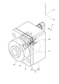
図1は、本実施形態の放射性核種製造装置を説明するための模式的な断面図である。図示した放射性核種製造装置1は、荷電粒子ビームPbを生成する加速器と、加速器によって生成された荷電粒子ビームPbの照射を受けて放射性同位元素(以下、「RI」と記す)を製造するターゲット装置と、を含んでいる。加速器とターゲット装置とは、図示しないボルト等によって互いに密着して取付けられていて、荷電粒子ビームPbだけが加速器3からターゲット装置5に入るように構成されている。
このような放射性核種製造装置は、外部への放射線漏れを防ぐために図示しない自己シールドを備えている。
[Radionuclide production equipment]
FIG. 1 is a schematic cross-sectional view for explaining the radionuclide production apparatus of this embodiment. The illustrated
Such a radionuclide production apparatus includes a self-shield (not shown) in order to prevent radiation leakage to the outside.
加速器3は、入射粒子を加速して荷電粒子ビームPbを生成する構成である。ターゲット物質に核反応を発生させる粒子ビームを構成する入射粒子には種々のものが用いられ、陽子、重陽子、α粒子、イオン、電子または光子を例示することができる。加速器3としては、静電加速器、サイクロトロンやシンクロトロン等の円形加速器、線形加速器、または円形加速器と線形加速器とを組み合わせたマイクロトロン等を用いることができ、入射粒子の種類とエネルギーに応じて選択される。
The
本実施形態の放射性核種製造装置は、1つの加速器3に複数のターゲット装置5が取付けられている。図1に示した例では、加速器3の図中の左右に例えばそれぞれ4つのターゲット装置を紙面に向かう方向(図中にZ軸で示す方向)に一列に設けている。
このような放射性核種製造装置において、加速器3に既存のものを使用し、ターゲット装置をより目的物の収量が上がるものに交換することがある。このとき、放熱効果を高めるため単にターゲット装置の表面積を大きくすると、加速器3に複数のターゲット装置を取り付け切れなくなる恐れが生じる。
ここで、ターゲット装置5は、いずれも図中のZ方向に並んで配置されている。このため、ターゲット装置5の表面積をZ方向以外の方向に大きくしても、ターゲット装置5を加速器3に取り付けることができる。
本実施形態は、上記の点に着目し、ターゲット装置5の表面積をZ方向以外に大きくし、放熱効果を高めながらも加速器3に対する取り付けへの影響をなくすようにしている。
In the radionuclide production apparatus of this embodiment, a plurality of
In such a radionuclide production apparatus, an existing one may be used for the
Here, all of the
In this embodiment, paying attention to the above points, the surface area of the
本実施形態の放射性核種製造装置は、加速器が荷電粒子ビームPbとして陽子線を生成する。そして、生成された陽子線を18MeV、50μAから100μAもしくはそれ以上の照射電流値でターゲット装置5に照射する。
本実施形態のターゲット装置5は、H2 18Oをターゲットとして保持している。ターゲットに荷電粒子ビームPbが照射されることにより、ターゲット装置5においてターゲットと陽子との間に18O(p,n)18Fで表される核反応が起こり、RIとして18Fが生成される。なお、このような核反応の表記は、ターゲット物質を左側、生成物を右側に記載し、入射粒子と飛び出す粒子を括弧内に併記することによって行われる。
In the radionuclide production apparatus of this embodiment, the accelerator generates a proton beam as the charged particle beam Pb. Then, the generated proton beam is irradiated to the
The
生成された18Fは、合成装置に送られる。合成装置は、18Fを標識前駆体化合物と合成し、FDG等を製造する。
なお、本実施形態は、ターゲットをH2 18Oとするものに限定されるものではない。例えば、ターゲットにH2Oを用い、16O(p,α)13Nの核反応によって13Nを生成することもできる。
The generated 18 F is sent to the synthesizer. The synthesizer synthesizes 18 F with a labeled precursor compound to produce FDG and the like.
Note that this embodiment is not limited to target Those in H 2 18 O. For example, H 2 O can be used as a target, and 13 N can be generated by a nuclear reaction of 16 O (p, α) 13 N.
[ターゲット装置]
(全体構成)
次に、本実施形態のターゲット装置5の全体構成を説明する。
図2は、本実施形態のターゲット装置5を説明するための斜視図である。なお、図1に示したターゲット装置5は、いずれも同様の構成を有している。このため、本実施形態は、1つのターゲット装置5を説明して他のターゲット装置5の説明に代えるものとする。図2に示したX,Y,Z座標は、図1に示した座標系と一致している。
[Target device]
(overall structure)
Next, the overall configuration of the
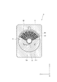
FIG. 2 is a perspective view for explaining the
ターゲット装置5は、荷電粒子ビームPbを液状のターゲットに照射して放射性核種を生成させる放射性核種製造装置のターゲット装置である。ターゲット装置5は、液状のターゲットを収容する容器である照射容器51と、照射容器51と連通し、荷電粒子ビームPbの照射によって気化したターゲットが拡散し得る空間を有するバッファ部53と、を備えている。照射容器51は、図示しないターゲットとしてH2 18Oを保持している。バッファ部53は、荷電粒子ビームPbの照射方向と直交する幅方向(図2中ではZ方向に沿っている)よりも荷電粒子ビームPbの照射方向に沿う長さ方向(図中に沿うX方向)に長い形状を有している。
The
上記ターゲット装置5は、ニオブ(Nb)やタンタル(Ta)などの耐食性に優れた金属材料で作られる。ターゲット装置は、このような金属材料の直径60mmの円筒形の塊を削って、もしくは流路を切った多層円板の拡散接合によって製造されている。照射容器51及びバッファ部53は、いずれも上記円筒形の塊を切削することによって金属材料の塊内に形成された空間である。また、本実施形態では、このような金属材料の塊を、以下、「ターゲットボディ」50と記す。なお、ニオブは、異核種の製造が抑えられる点で有利な部材である。
ターゲット装置5は、アルミニウム等の金属製の取付持具2によって加速器3に取り付けられる。取付持具2は、枠体21、23を有し、枠体21と枠体23との間にターゲット装置5を挟み込むようにしてターゲット装置5を加速器3に固定する。枠体21と枠体23とは、図示しないボルトやOリングを使って密着して留められる。
枠体21には加速器3から照射される荷電粒子ビームPbを通すビーム入射口31が設けられている。枠体21と照射容器51との境界には、荷電粒子ビームPbを通して空気や水等を通さない好適な厚さのフォイル52が設けられる。フォイル52には、例えば、HAVAR(登録商標)、チタン、ステンレス等が用いられる。
図2において図示を省くが、ターゲット装置5の荷電粒子ビームPbの入射側には、冷却水が循環する冷却水用枝管63(図2、図3及び図6参照)が設けられている。冷却水用枝管63には冷却水用本管60(図4及び図5参照)が接続されていて、冷却水用本管60を介して外部から冷却水用枝管63に冷却水が供給される。
なお、ターゲット装置5は、照射容器51とバッファ部53とを連通して両者の圧力を一定に保つ連通路57を備えている(図3及び図5参照)。連通路57を設けたことにより、バッファ部53の上端から照射容器51までの圧力が等しくなり、照射容器51内のターゲットの水位f1は照射容器51及びバッファ部53の圧力の値によらず一定に保たれる。
The
The
The
Although not shown in FIG. 2, a cooling water branch pipe 63 (see FIGS. 2, 3, and 6) through which the cooling water circulates is provided on the incident side of the charged particle beam Pb of the
The
図3は、図2に示したターゲット装置5を図中の+Y方向の側から見た上面図である。図3の上面図は一部模式的な図であって、冷却水用本管60の図示を省いて照射容器51の形状を見易くしている。図4は、図3に示した矢線A−Aに沿う断面図である。図5は、図3に示した矢線B−Bに沿う断面図である。図6は、図3に示した矢線C−Cに沿う断面図である。
FIG. 3 is a top view of the
ターゲット装置5は、図3に示したように、フィッティング71及びこのフィッティング71と接続する管路711を備えている。フィッティング71及び管路711は、バッファ部53及び照射容器51にHeガスや水を通すための構成である。また、ターゲット装置5は、フィッティング73及びこのフィッティング73と接続する管路731を備えている。フィッティング73及び管路731は、照射容器51から18Fを含むターゲットを回収するための構成である。
本実施形態では、図4に示した断面図の枠体23のX方向の長さを46.00mm、図5及び図6に示した断面図の枠体23のZ方向の最大長さを70.00mmとした。
As shown in FIG. 3, the
In the present embodiment, the length in the X direction of the
以下、上記した構成の各々について説明する。 Hereinafter, each of the above-described configurations will be described.
(照射容器)
図3に示すように、照射容器51は、上面視において略二等辺三角形をなす空洞である。また、照射容器51は、図4で示すように、荷電粒子ビームPbの入射方向と直交する面の断面積が荷電粒子ビームPbの照射方向(照射元から照射される側に向かう方向)に向かうに従って小さくなる形状を有している。照射容器51の断面は、図4に示したように図3に示した矢線B−B上において矢線C−C上におけるよりも大きくなっている。また、照射容器51の断面は、図3に示した矢線B−B上において円形であるのに対し、図4に示した矢線C−C上において楕円形状を有している。
(Irradiation container)
As shown in FIG. 3, the
照射容器51は、X方向(荷電粒子ビームPbの入射方向)に沿って狭くなる。このような形状を、本実施形態では、「コーン形状」ともいう。コーン形状は、荷電粒子ビームPbの強度がビームの入射方向に垂直な断面積の中央で強く、ターゲット中を進むにしたがって減衰することに応じて設計された形状である。照射容器51をコーン形状とすることによって、強度の強い荷電粒子ビームPbがターゲットの量の多い箇所に照射されるようになる。これにより、照射容器51における単位面積当たりの発熱量の減少と、冷却面の面積の増大の2点によって高い除熱効果を得ることができる。なお、照射容器51内に収容されるターゲットの量は、例えば2mlから4ml、最大で5ml程度である。
また、照射容器51は、荷電粒子ビームPbが入射する側から離れるに従って、荷電粒子ビームPbの中心軸に近づく底面を有している。つまり、照射容器51の底面は、荷電粒子ビームPbの入射側から奥に向かうにしたがって上方に向かって傾くようになっている。
The
Further, the
図4に示すように、照射容器51は、X方向に沿ってX方向に垂直な断面の面積が小さくなるように設計されている。ただし、図4から明らかなように、照射容器51は、図4に示した縦断面の上部511aと下部511bとの傾きが異なっている。つまり、照射容器51は、下部511bが上部511部よりも大きく傾いていることにより、液状のターゲットが沸騰することにより生じる荷電粒子ビームPbの飛程の差を補正(補償)することができる。このため、核反応の確率が上がり、放射性核種の収率が向上する。
As shown in FIG. 4, the
(バッファ部)
バッファ部53は、長さ方向が並列になるように複数配置され、複数のバッファ部53と照射容器51とを連通させて、バッファ部53において液化したターゲットを照射容器51に帰還させる連通路57をさらに有している。
本実施形態のターゲット装置5は、バッファ部53を複数(7つ)備えている。複数のバッファ部53は、図3に示すように、荷電粒子ビームPbの入射方向に長く形成されていて、長さ方向が互いに並列になるように配置されている。
また、複数のバッファ部53は、照射容器51の周面の接線方向に対して垂直かつ等間隔に立設されている。このため、複数のバッファ部53は、照射容器51に対して放射状に配置されることになる。
このような本実施形態によれば、ターゲット装置5におけるターゲットの冷却効果を高めるためにバッファ部53を荷電粒子ビームPbの入射方向に沿ってさらに長くし、バッファ部53の表面積を拡大することができる。
ターゲット装置5は前記したように枠体21と枠体23との間に挟み込んで固定される。このとき、バッファ部53の長さを長くしてターゲット装置5の長さが長くなった場合にも、ターゲット装置5を加速器3に取り付けることに支障は生じない。また、ターゲット装置5の長さが長くなった場合にも、Z方向の長さに変化がないため、ターゲット装置5を加速器3に対して取り付けるために必要な領域に変化はなく、既存のターゲット装置と同様にして加速器3に取り付けることができる。
(Buffer part)
A plurality of
The
In addition, the plurality of
According to the present embodiment, in order to increase the target cooling effect in the
The
また、図3、図5に示すように、連通路57は、複数のバッファ部53のうちの隣り合うバッファ部53同士を順次接続している。複数のバッファ部53が連通路57を介して連通することにより、照射容器51と複数のバッファ部53との圧力が等しくなり、照射容器51内においても、バッファ部53においてもターゲットの水位f1が等しくなる。
照射容器51において気化したターゲットは、少なくとも一部が照射容器51からバッファ部53のいずれかに入って冷却される。いずれかのバッファ部53において冷却されて液化したターゲットは、少なくとも一部がバッファ部53から直接照射容器51に落ちてくる。
また、バッファ部53において冷却されて液化したターゲットの少なくとも一部は、バッファ部53の先端と接続されている連通路57を介して他のバッファ部53に入り込む。そして、入り込んだ先のバッファ部53を伝って照射容器51に流入する。
さらに、連通路57と管路731とが接続されることにより、蒸発における圧力に均衡がもたらされる。その結果、ターゲットの水位f1を安定化させることができる。
As shown in FIGS. 3 and 5, the
At least a part of the target vaporized in the
In addition, at least a part of the target cooled and liquefied in the
Further, the
本実施形態では、バッファ部53の周壁に、金属触媒として、白金(Pt)のコーティング膜を形成してもよい。これにより、水の放射線分解により発生する水素、そして酸素の反応を促進して速やかに水を戻すことができるため、水素、酸素の非凝縮性ガスの発生による、ターゲット内圧の上昇を抑制するばかりでなく、水の放射線分解に生成物(ラジカル等)を抑制することが可能になる。
なお、白金コーティング膜の成膜は、蒸着やスパッタリング及び電解めっきのいずれの方法によっても実現することができる。
In the present embodiment, a coating film of platinum (Pt) may be formed on the peripheral wall of the
The formation of the platinum coating film can be realized by any method of vapor deposition, sputtering, and electrolytic plating.
さらに、本実施形態は、連通路57がHeガスや水が供給される管路711と接続されている。連通路57内に残ったターゲットは、管路711を介して連通路57に供給された水またはHeガスによって押し出され、照射容器51に帰還する。
Further, in this embodiment, the
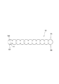
さらに、バッファ部53は、その周壁が、連続する複数の凹曲面531(図7参照)を含んでいる。
図7は、図3に示したバッファ部53の上面視を拡大して示した模式図である。図7に示したように、バッファ部53の対向する壁面W1、W2の表面には、夫々凹曲面531となっている。凹曲面531は、円533の円弧の一部が連続する形状を有している。このような壁面W1、W2を有するバッファ部53は、気化したターゲットと接触する内面の表面積が平面より大きくなって高い冷却効果を得ることができる。
Furthermore, as for the
FIG. 7 is a schematic diagram showing an enlarged top view of the
本実施形態は、バッファ部53の形成にあたり、凹曲面531を次のようにして形成する。すなわち、ターゲットボディ50を削ってバッファ部53を形成する本実施形態では、図示しないドリルを円柱のターゲットボディ50の周面から図1に示した−Y方向に差し込んで複数の縦穴を一部重なるようにしてX方向に形成する。互いに重なって一列に配置された縦穴は、X方向に延びるスリットのバッファ部53を形成する。なお、複数の縦穴のドリルを差し込んでできた外部と連通する箇所は所定の深さまで金属で埋められる。
第1実施形態の円533の径rは、例えば、2mm以上、5mm以下が好ましく、より好ましくは3mmである。径rを3mmとしたバッファ部53は、リフラックス(水の滴下)について好適に機能した実績を有している。
In this embodiment, when forming the
The diameter r of the
(動作)
次に、以上説明したターゲット装置の動作を説明する。
ターゲット装置5においては、荷電粒子ビームPbがフォイル52を通過して照射容器51に入射してくる。入射してきた荷電粒子ビームPbの陽子がターゲットの水素及び酸素の原子と衝突する。このとき、陽子と原子との間に熱が発生し、液状のターゲットが沸騰、気化する。気化したターゲットの少なくとも一部は、複数のバッファ部53のいずれかに入り込む。複数のバッファ部53は連通路57によって連通していることにより、圧力が均一となっている。このため、気化したターゲットは複数のバッファ部53に均等に入り込む。そして、ターゲットは、バッファ部53内においてターゲットボディ50の内面上で冷却されて水滴となる。水滴の少なくとも一部は、重力によって直接照射容器51に落下する経路を通って照射容器51に帰還する。
(Operation)
Next, the operation of the target device described above will be described.
In the
また、ターゲットの他の一部は、バッファ部53において冷却されて液化し、バッファ部53と連通する連通路57の周壁のターゲットボディ50の内面を伝って他のバッファ部53内に入り込む。他のバッファ部53においてターゲットの複数の液滴が一緒になると、液滴の体積及び重量が大きくなってターゲットボディ50の内面を滑り落ちやすくなる。ターゲットボディ50の内面を滑り落ちた液滴は、照射容器51に帰還する。
The other part of the target is cooled and liquefied in the
[放射性薬剤の製造方法]
次に、以上説明した放射性核種製造装置1によって生成された放射性核種を用い、放射性薬剤を製造する方法について説明する。
本方法は、放射性核種製造装置から放射性核種を回収する回収工程を含んでいる。回収工程では、ターゲットをターゲット装置5から回収し、陰イオン交換樹脂カートリッジにターゲットを通して18Fを吸着させることによって行われる。これを生理食塩液で溶出することで、18Fイオン(18F−NaF)を有効成分と放射性薬剤を得ることができる。また、本方法は、回収された18Fを使って標識前駆体化合物を標識する標識工程を含んでいてもよい。標識工程は、陰イオン交換樹脂カートリッジに吸着した18Fを炭酸カリウムやテトラブチルアンモニウム炭酸塩などの塩基で溶出した後、18Fを乾固して溶媒を除き、標識前駆体化合物とフッ素化反応させることによって行われる。例えば、標識前駆体化合物としてマンノーストリフレートを用いた場合は、標識工程の後、加水分解を行って、18F-フルオロデオキシグルコースを得ることができる。
[Method for producing radiopharmaceutical]
Next, a method for producing a radiopharmaceutical using the radionuclide generated by the
The method includes a recovery step of recovering the radionuclide from the radionuclide production apparatus. In the recovery step, the target is recovered from the
本実施形態の放射性薬剤の製造方法は、上記放射性核種製造装置で放射性核種を生成する工程を含むため、ターゲットの冷却効率の向上により照射するビーム量が向上することで、放射性核種の収量を高めることができる。したがって、より多くの放射性薬剤を製造することが可能になる。 The method for producing a radiopharmaceutical according to the present embodiment includes a step of generating a radionuclide with the above-described radionuclide production apparatus. Therefore, the yield of the radionuclide is increased by improving the beam amount to be irradiated by improving the cooling efficiency of the target. be able to. Therefore, it becomes possible to manufacture more radiopharmaceuticals.
上記実施形態は、以下の技術思想を包含するものである。
(1)粒子ビームを液状のターゲットに照射して放射性核種を生成させる放射性核種製造装置であって、
前記ターゲットを収容する容器と、
前記容器と連通し、前記粒子ビームの照射によって気化した前記ターゲットが拡散し得るバッファ部と、を備え、
前記バッファ部は、前記粒子ビームの照射方向と直交する幅方向よりも照射方向に沿う長さ方向に長い形状を有することを特徴とする放射性核種製造装置。
(2)前記バッファ部は前記長さ方向が並列になるように複数配置され、複数の前記バッファ部と前記容器とを連通させて、前記バッファ部において液化した前記ターゲットを前記容器に帰還させる連通路をさらに有する(1)に記載の放射性核種製造装置。
(3)前記容器は、前記粒子ビームの照射方向と直交する面の断面積が前記粒子ビームの照射方向に向かうに従って小さくなるコーン形状を有する(1)または(2)に記載の放射性核種製造装置。
(4)前記容器は、前記粒子ビームが入射する側から離れるに従って、前記粒子ビームの中心軸に近づく底面を有する(1)から(3)のいずれか1項に記載の放射性核種製造装置。
(5)前記バッファ部の周壁は、金属触媒を含む皮膜を備える(1)から4のいずれか1項に記載の放射性核種製造装置。
(6)前記バッファ部の周壁は、連続する複数の凹曲面を含む(1)から(5)のいずれか1項に記載の放射性核種製造装置。
(7)粒子ビームを液状のターゲットに照射して放射性核種を生成させる放射性核種製造装置のターゲット装置であって、
前記ターゲットを収容する容器と、
前記容器と連通し、前記粒子ビームの照射によって気化した前記ターゲットが拡散し得るバッファ部と、を備え、
前記バッファ部は、前記粒子ビームの照射方向と直交する幅方向よりも照射方向に沿う長さ方向に長い形状を有することを特徴とするターゲット装置。
(8)(1)から(5)のいずれか1項に記載の放射性核種製造装置によって製造された放射性核種を用いて放射性薬剤を製造する放射性薬剤の製造方法であって、
前記放射性核種製造装置から放射性核種を回収する回収工程と、
前記回収工程において回収された前記放射性核種を使って標識前駆体化合物を標識する標識工程と、を含む放射性薬剤の製造方法。
(9)粒子ビームを液状のターゲットに照射して放射性核種を生成させる放射性核種製造装置であって、
前記ターゲットを収容する容器と、
前記容器と連通し、前記粒子ビームの照射によって気化した前記ターゲットが拡散し得る複数のバッファ部と、を備え、
複数の前記バッファ部は、前記粒子ビームの照射方向に並んで配置されることを特徴とする放射性核種製造装置。
The above embodiment includes the following technical idea.
(1) A radionuclide production apparatus for generating a radionuclide by irradiating a liquid target with a particle beam,
A container containing the target;
A buffer unit communicating with the container and capable of diffusing the target vaporized by the irradiation of the particle beam,
The radionuclide manufacturing apparatus, wherein the buffer unit has a shape that is longer in a length direction along an irradiation direction than a width direction orthogonal to the irradiation direction of the particle beam.
(2) A plurality of the buffer units are arranged so that the length directions thereof are in parallel, and a plurality of the buffer units and the container communicate with each other, and the target liquefied in the buffer unit is returned to the container. The radionuclide production apparatus according to (1), further including a passage.
(3) The radionuclide production apparatus according to (1) or (2), wherein the container has a cone shape in which a cross-sectional area of a plane orthogonal to the particle beam irradiation direction decreases toward the particle beam irradiation direction. .
(4) The radionuclide manufacturing apparatus according to any one of (1) to (3), wherein the container has a bottom surface that approaches a central axis of the particle beam as the particle beam is separated from the incident side.
(5) The radionuclide manufacturing apparatus according to any one of (1) to (4), wherein the peripheral wall of the buffer unit includes a coating containing a metal catalyst.
(6) The radionuclide manufacturing apparatus according to any one of (1) to (5), wherein the peripheral wall of the buffer unit includes a plurality of continuous concave curved surfaces.
(7) A target device of a radionuclide production apparatus that generates a radionuclide by irradiating a liquid target with a particle beam,
A container containing the target;
A buffer unit communicating with the container and capable of diffusing the target vaporized by the irradiation of the particle beam,
The buffer device has a shape that is longer in the length direction along the irradiation direction than in the width direction orthogonal to the irradiation direction of the particle beam.
(8) A radiopharmaceutical production method for producing a radiopharmaceutical using a radionuclide produced by the radionuclide production apparatus according to any one of (1) to (5),
A recovery step of recovering the radionuclide from the radionuclide production apparatus;
A labeling step of labeling a labeled precursor compound using the radionuclide recovered in the recovery step.
(9) A radionuclide production apparatus for generating a radionuclide by irradiating a liquid target with a particle beam,
A container containing the target;
A plurality of buffer portions communicating with the container and capable of diffusing the target vaporized by the irradiation of the particle beam;
The radionuclide manufacturing apparatus, wherein the plurality of buffer units are arranged side by side in the particle beam irradiation direction.
1 放射性核種製造装置
2 取付持具
3 加速器
5 ターゲット装置
21,23 枠体
31 ビーム入射口
50 ターゲットボディ
51 照射容器
52 フォイル
57 連通路
60 冷却水用本管
63 冷却水用枝管
71,73 フィッティング
511a 上部
511b 下部
711、713 管路
531 凹曲面
533 円
W1,W2 壁面
DESCRIPTION OF
Claims (8)
前記ターゲットを収容する容器と、
前記容器と連通し、前記粒子ビームの照射によって気化した前記ターゲットが拡散し得るバッファ部と、を備え、
前記バッファ部は、前記粒子ビームの照射方向と直交する幅方向よりも照射方向に沿う長さ方向に長い形状を有することを特徴とする放射性核種製造装置。 A radionuclide production apparatus for generating a radionuclide by irradiating a liquid target with a particle beam,
A container containing the target;
A buffer unit communicating with the container and capable of diffusing the target vaporized by the irradiation of the particle beam,
The radionuclide manufacturing apparatus, wherein the buffer unit has a shape that is longer in a length direction along an irradiation direction than a width direction orthogonal to the irradiation direction of the particle beam.
前記ターゲットを収容する容器と、
前記容器と連通し、前記粒子ビームの照射によって気化した前記ターゲットが拡散し得るバッファ部と、を備え、
前記バッファ部は、前記粒子ビームの照射方向と直交する幅方向よりも照射方向に沿う長さ方向に長い形状を有することを特徴とするターゲット装置。 A target device of a radionuclide production apparatus that generates a radionuclide by irradiating a liquid target with a particle beam,
A container containing the target;
A buffer unit communicating with the container and capable of diffusing the target vaporized by the irradiation of the particle beam,
The buffer device has a shape that is longer in the length direction along the irradiation direction than in the width direction orthogonal to the irradiation direction of the particle beam.
前記放射性核種製造装置から前記放射性核種を回収する回収工程と、
前記回収工程において回収された前記放射性核種を用いて放射性薬剤を製造する放射性薬剤製造工程と、を含む放射性薬剤の製造方法。 A radionuclide generation step of generating a radionuclide by the radionuclide production apparatus according to any one of claims 1 to 6;
A recovery step of recovering the radionuclide from the radionuclide production apparatus;
And a radiopharmaceutical production step of producing a radiopharmaceutical using the radionuclide recovered in the recovery step.
Priority Applications (1)
| Application Number | Priority Date | Filing Date | Title |
|---|---|---|---|
| JP2016148945A JP6730874B2 (en) | 2016-07-28 | 2016-07-28 | Radionuclide manufacturing apparatus, target apparatus and method for manufacturing radiopharmaceutical |
Applications Claiming Priority (1)
| Application Number | Priority Date | Filing Date | Title |
|---|---|---|---|
| JP2016148945A JP6730874B2 (en) | 2016-07-28 | 2016-07-28 | Radionuclide manufacturing apparatus, target apparatus and method for manufacturing radiopharmaceutical |
Publications (2)
| Publication Number | Publication Date |
|---|---|
| JP2018017634A true JP2018017634A (en) | 2018-02-01 |
| JP6730874B2 JP6730874B2 (en) | 2020-07-29 |
Family
ID=61081267
Family Applications (1)
| Application Number | Title | Priority Date | Filing Date |
|---|---|---|---|
| JP2016148945A Active JP6730874B2 (en) | 2016-07-28 | 2016-07-28 | Radionuclide manufacturing apparatus, target apparatus and method for manufacturing radiopharmaceutical |
Country Status (1)
| Country | Link |
|---|---|
| JP (1) | JP6730874B2 (en) |
Cited By (1)
| Publication number | Priority date | Publication date | Assignee | Title |
|---|---|---|---|---|
| JP2020159931A (en) * | 2019-03-27 | 2020-10-01 | 住友重機械工業株式会社 | Target device |
Citations (8)
| Publication number | Priority date | Publication date | Assignee | Title |
|---|---|---|---|---|
| JPH10232297A (en) * | 1997-02-19 | 1998-09-02 | Toshiba Corp | Recombination treating method for combustible gas and its gas waste disposal facility |
| US20050084055A1 (en) * | 2003-09-25 | 2005-04-21 | Cti, Inc. | Tantalum water target body for production of radioisotopes |
| JP2008256628A (en) * | 2007-04-09 | 2008-10-23 | Hitachi Ltd | Target vessel for radionuclide production, radionuclide production device, and radionuclide production method |
| JP2011220930A (en) * | 2010-04-13 | 2011-11-04 | Sumitomo Heavy Ind Ltd | Target and target device |
| JP2012058236A (en) * | 2010-09-10 | 2012-03-22 | Ge-Hitachi Nuclear Energy Americas Llc | Devices and methods for managing noncombustible gasses in nuclear power plants |
| US20130266105A1 (en) * | 2010-10-27 | 2013-10-10 | Bernard Lambert | Device For Producing Radioisotopes |
| JP2013246131A (en) * | 2012-05-29 | 2013-12-09 | Sumitomo Heavy Ind Ltd | Ri manufacturing apparatus |
| US20160141062A1 (en) * | 2014-11-19 | 2016-05-19 | General Electric Company | Target body for an isotope production system and method of using the same |
-
2016
- 2016-07-28 JP JP2016148945A patent/JP6730874B2/en active Active
Patent Citations (9)
| Publication number | Priority date | Publication date | Assignee | Title |
|---|---|---|---|---|
| JPH10232297A (en) * | 1997-02-19 | 1998-09-02 | Toshiba Corp | Recombination treating method for combustible gas and its gas waste disposal facility |
| US20050084055A1 (en) * | 2003-09-25 | 2005-04-21 | Cti, Inc. | Tantalum water target body for production of radioisotopes |
| JP2008256628A (en) * | 2007-04-09 | 2008-10-23 | Hitachi Ltd | Target vessel for radionuclide production, radionuclide production device, and radionuclide production method |
| JP2011220930A (en) * | 2010-04-13 | 2011-11-04 | Sumitomo Heavy Ind Ltd | Target and target device |
| JP2012058236A (en) * | 2010-09-10 | 2012-03-22 | Ge-Hitachi Nuclear Energy Americas Llc | Devices and methods for managing noncombustible gasses in nuclear power plants |
| US20130266105A1 (en) * | 2010-10-27 | 2013-10-10 | Bernard Lambert | Device For Producing Radioisotopes |
| JP2013246131A (en) * | 2012-05-29 | 2013-12-09 | Sumitomo Heavy Ind Ltd | Ri manufacturing apparatus |
| US20160141062A1 (en) * | 2014-11-19 | 2016-05-19 | General Electric Company | Target body for an isotope production system and method of using the same |
| JP2017538926A (en) * | 2014-11-19 | 2017-12-28 | ゼネラル・エレクトリック・カンパニイ | Target body for isotope production system and method of use thereof |
Cited By (1)
| Publication number | Priority date | Publication date | Assignee | Title |
|---|---|---|---|---|
| JP2020159931A (en) * | 2019-03-27 | 2020-10-01 | 住友重機械工業株式会社 | Target device |
Also Published As
| Publication number | Publication date |
|---|---|
| JP6730874B2 (en) | 2020-07-29 |
Similar Documents
| Publication | Publication Date | Title |
|---|---|---|
| JP4541445B2 (en) | Radioisotope production apparatus and radioisotope production method | |
| US20060062342A1 (en) | Method and apparatus for the production of radioisotopes | |
| US20160141062A1 (en) | Target body for an isotope production system and method of using the same | |
| JP2007523332A (en) | Target equipment for radioisotope production | |
| JP2017156143A (en) | Target device and radionuclide production device | |
| JP4099187B2 (en) | Radioisotope production apparatus and target recycling method | |
| US20200035373A1 (en) | High efficiency neutron capture product production | |
| Thisgaard et al. | Medium to large scale radioisotope production for targeted radiotherapy using a small PET cyclotron | |
| JP2013246131A (en) | Ri manufacturing apparatus | |
| US8670513B2 (en) | Particle beam target with improved heat transfer and related apparatus and methods | |
| JP6730874B2 (en) | Radionuclide manufacturing apparatus, target apparatus and method for manufacturing radiopharmaceutical | |
| JP2014044098A (en) | Charged particle irradiation target refrigerating apparatus, charged particle irradiation target, and neutron generating method | |
| JP5442523B2 (en) | Target and target device | |
| JP2018013465A (en) | Radioactive nuclide production device, target device and manufacturing method of radioactive medicine | |
| JP4994589B2 (en) | Target for radioisotope production | |
| JP4410716B2 (en) | Radioisotope production equipment | |
| US10354771B2 (en) | Isotope production system having a target assembly with a graphene target sheet | |
| JP7183098B2 (en) | Target device | |
| KR101130997B1 (en) | Device and method for producing radioisotopes | |
| JP7445491B2 (en) | target device | |
| DK2425686T3 (en) | Particle beam targets with improved heat transfer and associated method | |
| Martin et al. | Preliminary production of 211At at the Texas A&M University Cyclotron Institute | |
| JP2022152583A (en) | Ri production apparatus and target storage device | |
| Pashentsev | Production of radionuclides for cyclotron positron-emission tomography | |
| Habs et al. | Laser-driven radiation therapy |
Legal Events
| Date | Code | Title | Description |
|---|---|---|---|
| A621 | Written request for application examination |
Free format text: JAPANESE INTERMEDIATE CODE: A621 Effective date: 20190607 |
|
| A977 | Report on retrieval |
Free format text: JAPANESE INTERMEDIATE CODE: A971007 Effective date: 20200605 |
|
| TRDD | Decision of grant or rejection written | ||
| A01 | Written decision to grant a patent or to grant a registration (utility model) |
Free format text: JAPANESE INTERMEDIATE CODE: A01 Effective date: 20200623 |
|
| A61 | First payment of annual fees (during grant procedure) |
Free format text: JAPANESE INTERMEDIATE CODE: A61 Effective date: 20200703 |
|
| R150 | Certificate of patent or registration of utility model |
Ref document number: 6730874 Country of ref document: JP Free format text: JAPANESE INTERMEDIATE CODE: R150 |
|
| R250 | Receipt of annual fees |
Free format text: JAPANESE INTERMEDIATE CODE: R250 |