JP2018016355A - container - Google Patents
container Download PDFInfo
- Publication number
- JP2018016355A JP2018016355A JP2016148088A JP2016148088A JP2018016355A JP 2018016355 A JP2018016355 A JP 2018016355A JP 2016148088 A JP2016148088 A JP 2016148088A JP 2016148088 A JP2016148088 A JP 2016148088A JP 2018016355 A JP2018016355 A JP 2018016355A
- Authority
- JP
- Japan
- Prior art keywords
- fitting
- container
- portions
- fitting portions
- flange portion
- Prior art date
- Legal status (The legal status is an assumption and is not a legal conclusion. Google has not performed a legal analysis and makes no representation as to the accuracy of the status listed.)
- Granted
Links
Images


Abstract
Description
本発明は、開封後に再封可能な容器に関する。 The present invention relates to a resealable container after opening.
食材を収容する容器には、食材の改竄や劣化を防止するため密封することが求められる。また、食材を1回の食事では食べきれないことが想定される場合、あるいは佃煮や漬物等のように食材を少量ずつ消費することが想定される場合には、開封後に再封できることが求められる。 Containers containing food materials are required to be sealed to prevent the food materials from being tampered with or deteriorated. In addition, if it is assumed that the food cannot be eaten in one meal, or if it is assumed that the food is consumed little by little, such as boiled or pickled, it is required to be able to reseal after opening. .
上記のように密封性と再封性が求められる容器は、一般的に3つの部品、すなわち容器本体とシール蓋材と再封蓋とを備えている。容器本体は、食材を収容する収容部と、この収容部の開口周縁に連なるフランジ部を有している。シール蓋材はフィルム状またはシート状をなし、フランジ部に熱溶着されている。この熱溶着により収容部の内部空間が密封されている。再封蓋は、フランジ部に着脱可能に被せられている。 As described above, a container that requires sealing and resealability generally includes three parts, that is, a container body, a sealing lid member, and a resealing lid. The container main body has a housing portion for containing the foodstuff, and a flange portion connected to the opening periphery of the housing portion. The seal lid material is in the form of a film or a sheet and is thermally welded to the flange portion. The internal space of the housing portion is sealed by this heat welding. The reseal lid is detachably placed on the flange portion.
上記容器から食材を取出す場合には、再封蓋をフランジ部から外し、シール蓋材をフランジ部から剥がす。シール蓋材はフランジ部から剥がした後は再封することができないが、再封蓋を再度フランジ部に被せることにより、再封することができる。 When taking out foodstuff from the said container, a reseal lid is removed from a flange part and a seal lid material is peeled from a flange part. The seal lid material cannot be resealed after being peeled off from the flange portion, but can be resealed by covering the flange portion with the reseal lid again.
上記容器は、容器本体の他に、密封用のシール蓋材と再封蓋を必要とするため製造コストが嵩んでしまう。
特許文献1の図10には、容器本体と、この容器本体のフランジ部に熱溶着されたシール蓋材からなる容器が開示されている。フランジ部には、外力によって切断可能な切断予定ラインが環状線を描いて形成されている。収容部の開口周縁とフランジ部の外周縁は四角形をなしており、切断予定ラインもこれら開口周縁と外周縁に沿って四角形をなしている。フランジ部には、切断予定ラインの4つの辺の中央において、下に凸の膨出部が形成されている。
The container requires a sealing lid material for sealing and a reseal lid in addition to the container main body, and thus the manufacturing cost increases.
FIG. 10 of Patent Document 1 discloses a container composed of a container main body and a seal lid material thermally welded to a flange portion of the container main body. In the flange portion, a planned cutting line that can be cut by an external force is formed by drawing an annular line. The opening peripheral edge of the housing part and the outer peripheral edge of the flange part form a quadrangle, and the line to be cut also forms a quadrangle along the opening peripheral part and the outer peripheral edge. The flange portion has a bulging portion protruding downward at the center of the four sides of the line to be cut.
特許文献1の容器では、シール蓋材とフランジ部の熱溶着により収容部の内部空間が密封されている。開封時に、フランジ部の切断予定ラインより外側の領域とシール蓋材を指でつまんで上方に折り曲げるように力を加えることにより、フランジ部は切断予定ラインで切断される。これにより、収容部とフランジ部の内側領域(切断予定ラインの内側の領域)からなる容器本体と、シール蓋材とフランジ部の外側領域からなる再封蓋に分離される。
上記切断予定ラインでの切断により、膨出部は内側部分と外側部分に分離される。
In the container of Patent Document 1, the internal space of the housing portion is sealed by thermal welding of the seal lid member and the flange portion. At the time of opening, the flange portion is cut along the planned cutting line by pinching the region outside the planned cutting line of the flange portion and the seal lid with a finger and bending it upward. Thereby, it isolate | separates into the container main body which consists of an accommodating part and the inner area | region (area | region inside a cutting scheduled line) of a flange part, and the reseal lid | cover which consists of a sealing lid material and the outer area | region of a flange part.
The bulging portion is separated into an inner portion and an outer portion by cutting along the planned cutting line.
再封時には、上記再封蓋を容器本体のフランジ部の内側領域に被せる。この際、容器本体に属する膨出部の内側部分のエッジと、再封蓋に属する膨出部の外側部分のエッジとの引っ掛かりにより、再封蓋の閉じ状態を保持する。
上記のように密封用のシール蓋材が、開封後には容器本体のフランジ部の外側領域と協働して再封蓋を構成するので、再封蓋を別途必要とせず部品点数を減じることができる。
At the time of resealing, the reseal lid is placed on the inner area of the flange portion of the container body. At this time, the closed state of the reseal lid is held by the hook between the edge of the inner portion of the bulging portion belonging to the container body and the edge of the outer portion of the bulging portion belonging to the reseal lid.
As described above, since the sealing lid member for sealing forms a reseal lid in cooperation with the outer region of the flange portion of the container body after opening, it is possible to reduce the number of parts without requiring a reseal lid separately. it can.
特許文献1の容器では、再封蓋の容器本体への閉じ状態を、半分に切断された膨出部の内側部分と外側部分のエッジでの引っ掛かりにより保持するため、確実に保持することができない。 In the container of Patent Document 1, the closed state of the reseal lid to the container body is held by catching at the edge of the inner part and the outer part of the bulged part cut in half, so that it cannot be reliably held. .
本発明は上記課題を解決するためになされたもので、
容器本体とシール蓋材とを備えた容器において、
上記容器本体は、収容部と、この収容部の開口周縁に連なるフランジ部とを有し、
上記フランジ部には、外力付与により切断可能な切断予定ラインが環状線を描いて形成され、この切断予定ラインにより上記フランジ部は内側領域と外側領域に区分けされ、このフランジ部の外側領域に上記シール蓋材が固着されており、
上記フランジ部の上記内側領域には第1嵌合部が形成され、上記外側領域には第2嵌合部が形成されており、
上記切断予定ラインでの切断により、上記フランジ部の外側領域と上記シール蓋材を含む再封蓋が、上記フランジ部の内側領域から分離可能であり、
上記再封蓋が上記収容部の開口を覆った状態で上記第1嵌合部と上記第2嵌合部が嵌合可能であることを特徴とする。
The present invention has been made to solve the above problems,
In a container provided with a container body and a seal lid,
The container body has a housing portion and a flange portion connected to the opening periphery of the housing portion,
The flange portion is formed with a cutting line that can be cut by applying external force in an annular line, and the cutting portion line divides the flange portion into an inner region and an outer region. The seal lid is fixed,
A first fitting portion is formed in the inner region of the flange portion, and a second fitting portion is formed in the outer region,
By the cutting at the scheduled cutting line, the reseal lid including the outer region of the flange portion and the seal lid member can be separated from the inner region of the flange portion,
The first fitting portion and the second fitting portion can be fitted in a state where the reseal lid covers the opening of the housing portion.
上記構成によれば、密封用のシール蓋材が、開封後には容器本体のフランジ部の外側領域と協働して再封蓋を構成するので、再封蓋を別途必要とせず部品点数を減じることができる。
しかも、開封後に再封蓋の第2嵌合部をフランジ部の内側領域の第1嵌合部に嵌合させることにより、再封蓋を、収容部開口を覆った状態で確実に保持することができる。
According to the above configuration, the sealing lid member for sealing forms the resealing lid in cooperation with the outer region of the flange portion of the container body after opening, thus reducing the number of parts without requiring a resealing lid separately. be able to.
Moreover, after the opening, the second fitting portion of the reseal lid is fitted to the first fitting portion in the inner region of the flange portion, thereby securely holding the reseal lid in a state of covering the opening of the accommodating portion. Can do.
好ましくは、上記第1嵌合部が複数形成され、上記第2嵌合部が上記第1嵌合部と同数形成されている。
上記構成によれば、複数箇所で嵌合するので、再封蓋をより一層確実に保持することができる。
Preferably, a plurality of the first fitting portions are formed, and the same number of the second fitting portions as the first fitting portions are formed.
According to the said structure, since it fits in multiple places, a reseal lid | cover can be hold | maintained still more reliably.
好ましくは、上記複数の第1嵌合部が周方向に等角度間隔をなして配置され、上記複数の第2嵌合部が周方向に等角度間隔をなして配置されるとともに上記第1嵌合部から周方向に離間して配置され、上記第1、第2嵌合部が上記収容部の中心から等距離離れている。
上記構成によれば、複数の嵌合箇所が等角度間隔をなしているので、再封蓋をより一層確実に保持することができる。また、再封蓋を容器本体に対して開封直後の位置から回すだけで、第1嵌合部と第2嵌合部を位置決めすることができる。
Preferably, the plurality of first fitting portions are arranged at equiangular intervals in the circumferential direction, and the plurality of second fitting portions are arranged at equiangular intervals in the circumferential direction, and the first fitting is performed. The first and second fitting portions are spaced apart from the joint portion in the circumferential direction, and are equidistant from the center of the housing portion.
According to the above configuration, since the plurality of fitting portions are equiangularly spaced, the reseal lid can be held more reliably. Moreover, a 1st fitting part and a 2nd fitting part can be positioned only by rotating a reseal lid with respect to a container main body from the position immediately after opening.
好ましくは、上記第1嵌合部と上記第2嵌合部が2つずつ形成され、上記第1、第2嵌合部は周方向に離れて配置されるとともに上記収容部の中心から等距離離れて配置されており、上記2つの第1嵌合部間の角度間隔と上記2つの第2嵌合部間の角度間隔が等しい。
上記構成によれば、2箇所で嵌合するので再封蓋を確実に保持できる。また、再封蓋を容器本体に対して開封直後の位置から回すだけで、第1嵌合部と第2嵌合部を位置決めすることができる。
Preferably, two each of the first fitting portion and the second fitting portion are formed, and the first and second fitting portions are spaced apart in the circumferential direction and are equidistant from the center of the housing portion. The angular intervals between the two first fitting portions are equal to the angular intervals between the two second fitting portions.
According to the said structure, since it fits in two places, a reseal lid can be hold | maintained reliably. Moreover, a 1st fitting part and a 2nd fitting part can be positioned only by rotating a reseal lid with respect to a container main body from the position immediately after opening.
好ましくは、上記2つの第1嵌合部は上記収容部を挟んで反対側に配置されており、上記2つの第2嵌合部は、上記収容部を挟んで反対側に配置されている。
上記構成によれば、2つの嵌合箇所が収容部を挟んで反対側に配置されているので、再封蓋をより一層確実に保持することができる。
Preferably, the two first fitting portions are disposed on the opposite sides with the accommodating portion interposed therebetween, and the two second fitting portions are disposed on the opposite sides with the accommodating portion interposed therebetween.
According to the said structure, since two fitting locations are arrange | positioned on both sides on both sides of an accommodating part, a reseal lid | cover can be hold | maintained still more reliably.
好ましくは、上記2つの第1嵌合部は互いに周方向に180°離れて配置され、上記2つの第2嵌合部は互いに周方向に180°離れるとともに上記第1嵌合部から周方向に90°離れて配置されている。
上記構成によれば、2つの嵌合箇所が周方向に180°離れているので、再封蓋10をより一層確実に保持することができる。また、第1嵌合部と第2嵌合部が交互に90°間隔で配置されているので、容器全体をバランス良く構成することができる。
Preferably, the two first fitting portions are disposed 180 degrees apart from each other in the circumferential direction, and the two second fitting portions are separated from each other by 180 degrees in the circumferential direction and from the first fitting portion in the circumferential direction. 90 ° apart.
According to the said structure, since the two fitting locations are 180 degree apart in the circumferential direction, the reseal lid |
好ましくは、上記収容部の上記開口周縁が八角形をなし、上記フランジ部の外周縁が四角形をなし、上記開口周縁の4つの辺が上記外周縁の4つの辺と平行をなしており、上記開口周縁の他の4つの辺が上記外周縁の4つの角部と協働して4つの略三角形状の領域を形成しており、これら4つの領域に、上記第1嵌合部と上記第2嵌合部が周方向に交互に配置されている。
上記構成によれば、フランジ部の全域を有効に活用でき、フランジ部に対する収容部の比を大きくすることができる。
Preferably, the opening periphery of the housing portion forms an octagon, the outer periphery of the flange portion forms a quadrangle, the four sides of the opening periphery are parallel to the four sides of the outer periphery, The other four sides of the peripheral edge of the opening cooperate with the four corners of the outer peripheral edge to form four substantially triangular regions. In these four regions, the first fitting portion and the first Two fitting parts are alternately arranged in the circumferential direction.
According to the said structure, the whole region of a flange part can be utilized effectively and the ratio of the accommodating part with respect to a flange part can be enlarged.
他の態様では、上記第1嵌合部と上記第2嵌合部が2つずつ形成され、上記2つの第1嵌合部間の離間距離と、上記2つの第2嵌合部間の離間距離が等しい。
上記構成によれば、再封蓋を容器本体に対して開封直後の位置から回動及び/又は直線的移動により、第1嵌合部と第2嵌合部を位置決めすることができる。
In another aspect, two each of the first fitting portion and the second fitting portion are formed, a separation distance between the two first fitting portions, and a separation distance between the two second fitting portions. The distance is equal.
According to the said structure, a 1st fitting part and a 2nd fitting part can be positioned by rotation and / or linear movement from the position immediately after opening a reseal lid with respect to a container main body.
好ましくは、上記複数の第2嵌合部は、対応する上記第1嵌合部から上記フランジ部の面に沿って所定方向に延びる直線上に配置されるとともに、対応する上記第1嵌合部との離間距離が等しい。
上記構成によれば、再封蓋を容器本体に対して開封直後の位置から直線的に移動することにより、第1嵌合部と第2嵌合部を位置決めすることができる。
Preferably, the plurality of second fitting portions are arranged on a straight line extending in a predetermined direction along the surface of the flange portion from the corresponding first fitting portion, and the corresponding first fitting portion. The separation distance is equal.
According to the said structure, a 1st fitting part and a 2nd fitting part can be positioned by linearly moving a reseal lid with respect to a container main body from the position immediately after opening.
好ましくは、上記フランジ部の上記内側領域には環状線をなす隆起部が形成され、上記第1嵌合部が上記隆起部より内側に配置されており、上記シール蓋材が上記隆起部と上記フランジ部の外側領域に熱溶着されている。
上記構成によれば、二重シールにより密封性を高めることができる。
Preferably, a raised portion that forms an annular line is formed in the inner region of the flange portion, the first fitting portion is disposed on the inner side of the raised portion, and the seal lid member is formed with the raised portion and the raised portion. It is heat welded to the outer region of the flange portion.
According to the said structure, sealing performance can be improved by a double seal.
上記第1、第2嵌合部が下に凸に膨出しており、上記第1嵌合部が雌型嵌合部として提供され、上記第2嵌合部が雄型嵌合部として提供される。
上記構成によれば、第1、第2嵌合部がフランジ部から突出しないので、容器を安定して積み重ねることができる。
The first and second fitting portions bulge downward, the first fitting portion is provided as a female fitting portion, and the second fitting portion is provided as a male fitting portion. The
According to the said structure, since a 1st, 2nd fitting part does not protrude from a flange part, a container can be stacked stably.
好ましくは、上記第1、第2嵌合部は、下方に向かって漸次径が増大する。
上記構成によれば、嵌合強度を高めることができる。
Preferably, the diameters of the first and second fitting portions gradually increase downward.
According to the above configuration, the fitting strength can be increased.
本発明によれば、少ない部品点数で密封性と再封性を得ることができる。 According to the present invention, sealing performance and resealability can be obtained with a small number of parts.
以下、本発明の第1実施形態をなす容器について図1〜図6を参照しながら説明する。本実施形態の容器は食材等を収容するためのものである。
最初に、図1、図2(A),(B)、図6(A),(B)を参照しながら容器の構成を説明する。容器は、容器本体10とシール蓋材20により構成されている。
容器本体10は、例えば樹脂シートを真空プレス成形することにより得られ、収容部11と、この収容部11の開口周縁11xに連なり径方向外方向に張り出すフランジ部12と,このフランジ部12の外周縁12xに連なる垂下部13とを有している。収容部11は底部11aと胴部11bにより構成されている。
Hereinafter, the container which makes 1st Embodiment of this invention is demonstrated, referring FIGS. The container of this embodiment is for accommodating food materials and the like.
Initially, the structure of a container is demonstrated, referring FIG. 1, FIG. 2 (A), (B), FIG. 6 (A), (B). The container is composed of a
The container
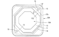
図1に示すように、上記収容部11の底部11aは略正八角形に近い八角形をなし、開口周縁11xはこの底部11aより若干大きな略相似形の八角形をなしている。
上記フランジ部12の外周縁12xは角部の丸みを除いて略正方形(四角形)をなしている。開口周縁11xの4つの辺は、外周縁12xの4つの辺とそれぞれ平行をなしている。開口周縁11xの他の4つの辺は外周縁12xの4つの角部と協働して、4つの略三角形状の領域12yを提供している。
As shown in FIG. 1, the
The outer
上記フランジ部12の4つの三角形状の領域12yの中央には、第1嵌合部15と第2嵌合部16が2つずつ形成されている。第1嵌合部15と第2嵌合部16は周方向に交互に配置されている。2つの第1嵌合部15は収容部11を挟んで反対側に配置されている。より具体的には周方向に180°離れている。2つの第2嵌合部16も収容部11を挟んで反対側に配置されている(周方向に180°離れている)。
第1嵌合部15と第2嵌合部16は周方向に90°離れており、収容部11の中心Lから等距離離れている。
Two first
The first
上記フランジ部12には、環状線を描く切断予定ライン17と、この切断予定ライン17の径方向内側において切断予定ライン17に沿って環状線を描く隆起部18が形成されている。図1では切断予定ライン17を破線で示し、図2(A),(B)、図6(A),(B)では、切断予定ライン17の位置を一点鎖線で示す。
The
切断予定ライン17は、フランジ部12に間隔をおいて形成された多数の切込みからなるミシン目でもよいし、フランジ部12の上面または下面に形成された連続したV溝であってもよい。切断予定ライン17は、フランジ部12の他の部位より脆弱であり、ユーザーから付与される外力で容易に切断できるようになっている。隆起部18は、フランジ部12の上面から若干量(例えば0.5mm程度)隆起している。
The scheduled
図1に示すように、切断予定ライン17と隆起部18は、第2嵌合部16が形成された三角形状の領域12yを除いて、フランジ部12の外周縁12xに沿いこの外周縁12xと平行をなして延びており、第2嵌合部16が形成された三角形状の領域12yでは、収容部11の開口周縁12xの辺に近接して当該辺と平行をなして延びている。その結果、切断予定ライン17と隆起部18は、第1嵌合部15の外側を通り、第2嵌合部16の内側を通っている。
As shown in FIG. 1, the
上記切断予定ライン17により、フランジ部12は内側領域12aと外側領域12bに区分けされている。この内側領域12aに、上記第1嵌合部15と隆起部18が配置され、外側領域12bに上記第2嵌合部16が配置されている。
The
図2(A),(B)に示すように、上記第1嵌合部15と第2嵌合部16は下に凸となるように膨出されており、下方に向かって径が漸次増大するようになっている。後述するように、第1嵌合部15が上方に開放された雌型嵌合部として提供され、第2嵌合部16が下方に突出する雄型嵌合部として提供される。第2嵌合部16は第1嵌合部15より肉厚分だけ小径をなしている。第2嵌合部16の下端部外径(最大外径)は、第1嵌合部15の上端部内径(最小内径)より若干大きい。
As shown in FIGS. 2A and 2B, the first
図2(A),(B)、図6(A),(B)に示すように、上記容器本体10の収容部11に食材を充填した後、フランジ部12に、上記シール蓋材20が熱溶着される。詳述すると、シール蓋材20は例えば樹脂フィルムまたは樹脂シートからなり、フランジ部12に対応して正方形をなしている。シール蓋材20は、フランジ部12の外側領域12bと隆起部18に熱溶着され、これにより、収容部11の内部空間が密封され、食材の改竄、劣化を防止できる。
2 (A), 2 (B), 6 (A), and 6 (B), after the
上記食材入りの容器を購入したユーザーは、フランジ部12の外側領域12bにおける2つの三角形状の領域12y(第2嵌合部16が形成された三角形状の領域12y)のいずれか一方を指でつまんで上側へ折り曲げることにより、この領域12yの切断予定ライン17を切断する。さらにこの領域12yを引き上げることにより、切断予定ライン17を全周にわたって切断する。
The user who has purchased the container containing the above-described foodstuff uses his / her finger to point out one of the two
上記切断予定ライン17での切断により、図6(C)に示すように容器は容器本体10Aと再封蓋20Aに分離される。この際、隆起部18とシール蓋材20との溶着も解除され、ユーザーは開封状態の収容部11から食材を取出すことができる。
By cutting along the
図3(A)、図6(C)に示すように、容器本体10Aは、初期状態の容器本体10からフランジ部12の外側領域12bを除去したものであり、収容部11とフランジ部12の内側領域12aを有している。第1嵌合部15と隆起部18は、容器本体10Aに属している。
As shown in FIGS. 3A and 6C, the
図3(B)、図6(C)に示すように、再封蓋20Aは、フランジ部12の外側領域12bと、垂下部13と、外側領域12bに溶着されたシール蓋材20を有している。第2嵌合部16は再封蓋20Aに属している。
As shown in FIGS. 3B and 6C, the
再封蓋20Aにおいて、シール蓋材20は柔軟性を有しているが、フランジ部12の外側領域12bと垂下部13は、成形品である初期状態の容器本体10の一部であるから、弾性変形可能であるものの保形性(所定の剛性)を有しており、再封蓋20Aの枠の役割を担う。
In the
再封蓋20Aにより、容器本体10Aの収容部11を再封することができる。この際、再封蓋20Aを、容器本体10Aから分離した直後の位置から90°回すことにより、図4、図5(A),(B)に示すように、再封蓋20Aの第2嵌合部16を容器本体10Aの第1嵌合部15に位置合わせし、第2嵌合部16を第1嵌合部15に嵌め込む。図1と図4の比較から明らかなように、再封蓋20Aは90°回しただけであり、収容部11に対する位置関係に大きな変化はなく、収容部11の開口をシール蓋材20で覆った再封状態が得られる。
The
第2嵌合部16の下端部外径が第1嵌合部15の上端部内径より若干大きいので、第2嵌合部16の下端部が第1嵌合部15の上端部を通過する際に、これら嵌合部15,16は弾性変形を伴う。
上記第1嵌合部15と第2嵌合部16は、180°離れた2箇所において嵌合すること、および上述したように弾性変形を伴って嵌合することにより、再封蓋20Aを容器本体10Aに確実に保持することができる。
Since the outer diameter of the lower end portion of the second
The first
次に、本発明の他の実施形態について図面を参照しながら説明する。これら実施形態において、先行する実施形態に対応する構成部には図において同番号または類似番号を付してその詳細な説明を省略する。 Next, another embodiment of the present invention will be described with reference to the drawings. In these embodiments, components corresponding to the preceding embodiments are given the same or similar numbers in the drawings, and detailed descriptions thereof are omitted.
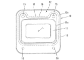
図7〜図9は本発明の第2実施形態を示す。図7に示すように、この実施形態では、第1実施形態とは逆に、収容部11の底部11aおよび開口周縁11xが略正方形をなし、フランジ部12の外周縁12xが正八角形に近い八角形をなしている。開口周縁の11xの4つの辺が外周縁12xの4つの辺と平行をなし、開口周縁の11xの4つの角部が外周縁12xの他の4つの辺に対応した位置にある。
7 to 9 show a second embodiment of the present invention. As shown in FIG. 7, in this embodiment, contrary to the first embodiment, the bottom 11a and the opening
フランジ部12には、開口周縁11xの4つの角部に対応して4つの第1嵌合部15が形成され、4つの辺に対応して4つの第2嵌合部16が形成されている。4つの第1嵌合部15は周方向に等角度間隔、すなわち90°間隔で配置され、4つの第2嵌合部16も90°間隔で配置されている。第1嵌合部15と第2嵌合部16は、45°間隔で離れており、収容部11の中心Lから等距離離れている。
Four first
切断予定ライン17と隆起部18は、開口周縁11xの辺に沿って第2嵌合部16の内側を通り、開口周縁11xの角部で第1嵌合部15の外側を円弧を描いて通っている。
The
切断予定ライン17での切断により、図9(A)に示す容器本体10Aと図9(B)に示す再封蓋20Aに分離される。再封蓋20Aは、分離直後の位置から45°回すことにより、図8に示すように第2嵌合部16を第1嵌合部15に位置合わせすることができる。これら第1嵌合部15と第2嵌合部16の嵌合により、再封蓋20Aのシール蓋材20(図示しない)が収容部11の開口を覆い、再封状態が得られる。
By cutting along the
図10〜図12は本発明の第3実施形態を示す。図10に示すように、容器本体10の収容部11の開口周縁11xは長方形をなし、フランジ部12の外周縁12xは正方形をなしている。フランジ部12は、開口周縁11xの2つの長辺と、この長辺と平行をなす外周縁12xの2つの辺との間に、比較的広い長方形の領域を有しており、一方の長方形の領域に2つの第1嵌合部15が形成され、他方の長方形の領域に第2嵌合部16が形成されている。
10 to 12 show a third embodiment of the present invention. As shown in FIG. 10, the opening
2つの第1嵌合部15は長軸方向(収容部11の長方形の長軸方向)に離間しており、2つの第2嵌合部16も長軸方向に離間している。第1嵌合部15間の離間距離と第2嵌合部16の離間距離は等しい。さらに、本実施形態では、2つの第1嵌合部15は収容部11の中心Lを通る短軸(収容部11の長方形の短軸)に対して対称に配置され、2つの第2嵌合部16も当該短軸に対称に配置されている。第1嵌合部15と第2嵌合部16の収容部11の中心Lから距離は異なっている。
切断予定ライン17と隆起部18は、開口周縁11xの辺に沿って延びるとともに第2嵌合部16の内側を通り、第1嵌合部15の外側を円弧を描いて通る。
The two first
The
切断予定ライン17での切断により、図12(A)に示す容器本体10Aと図12(B)に示す再封蓋20Aに分離される。再封蓋20Aは、分離直後の位置から180°回すとともに短軸方向(収容部11の長方形の短軸方向)にずらすことにより、図11に示すように第2嵌合部16を第1嵌合部15に位置合わせすることができる。これら第1嵌合部15と第2嵌合部16の嵌合により、再封蓋20Aのシール蓋材20(図示しない)が収容部11の開口を覆い、再封状態が得られる。
By cutting along the scheduled cutting
図13〜図15は本発明の第4実施形態を示す。図13に示すように、容器本体10の収容部11の開口周縁11xが長方形をなし、フランジ部12の外周縁12xが正方形をなしている点で第3実施形態と似ているが、本実施形態では、開口周縁11xの中心と外周縁12xの中心が収容部11の長方形の長軸方向にずれている。
13 to 15 show a fourth embodiment of the present invention. As shown in FIG. 13, this embodiment is similar to the third embodiment in that the opening
フランジ部12において、開口周縁11xの対角線上に位置する2つの角部の近傍に、第1嵌合部15が形成されている。2つの第1嵌合部15は収容部11の中心Lに対して等距離離れるとともに周方向に180°離れている。フランジ部12において、2つの第1嵌合部15から開口周縁11xの長軸方向に沿って等距離離れた位置にそれぞれ第2嵌合部16が形成されている。
切断予定ライン17と隆起部18は、開口周縁11xの辺に沿って延びるとともに第2嵌合部16の内側を通り、第1嵌合部15の外側を円弧を描いて通っている。
In the
The
切断予定ライン17での切断により、図15(A)に示す容器本体10Aと図15(B)に示す再封蓋20Aに分離される。再封蓋20Aは、分離直後の位置から開口周縁11xの長軸方向に直線的に移動させることにより、図14に示すように第2嵌合部16を第1嵌合部15に位置合わせすることができる。第1嵌合部15と第2嵌合部16の嵌合により、再封蓋20Aのシール蓋材20(図示しない)が収容部11の開口を覆い、再封状態が得られる。
By cutting along the
なお、第4実施形態では、一方の第1嵌合部15と一方の第2嵌合部16が収容部の中心Lに対して点対称をなし、他方の第1嵌合部15と他方の第2嵌合部16も中心Lに対して点対称をなしているので、再封蓋20Aを180°回しても嵌合状態を得ることができる。
In the fourth embodiment, one first
本発明は、上記実施形態に制約されず、種々の態様を採用することができる。例えば第1、第2嵌合部は上に凸に膨出してもよい。この場合、第1嵌合部は下側が開放さえた雌型嵌合部として提供され、第2嵌合部は上に突出する雄型嵌合部として提供される。
上記実施形態では第1、第2嵌合部は円形であったが、形状に制約はなく、多角形状であってもよい。
上記実施形態では容器本体とシール蓋材が樹脂製であったが、いずれか一方または両方が、樹脂以外の材料例えば紙や金属であってもよい。
また、容器の収容部の形状は多角形状に限らず円形や楕円形であってもよいし、フランジ部の外周縁形状も多角形状に限らず円形や楕円形であってもよい。
The present invention is not limited to the above embodiment, and various aspects can be adopted. For example, the first and second fitting portions may bulge upward. In this case, the first fitting portion is provided as a female fitting portion whose lower side is even opened, and the second fitting portion is provided as a male fitting portion protruding upward.
In the said embodiment, although the 1st, 2nd fitting part was circular, there is no restriction | limiting in a shape and polygonal shape may be sufficient.
In the above embodiment, the container body and the seal lid member are made of resin, but either one or both may be a material other than resin, such as paper or metal.
Moreover, the shape of the container accommodating portion is not limited to a polygonal shape, and may be a circle or an ellipse, and the outer peripheral edge shape of the flange portion is not limited to a polygonal shape and may be a circle or an ellipse.
本発明は、食材の容器等に適用できる。 The present invention can be applied to food containers and the like.
10 容器本体
10A 開封後の容器本体
11 収容部
11x 開口周縁
12 フランジ部
12a 内側領域
12b 外側領域
12x 外周縁
15 第1嵌合部
16 第2嵌合部
17 切断予定ライン
18 隆起部
20 シール蓋材
20A 再封蓋
DESCRIPTION OF
Claims (12)
上記容器本体は、収容部と、この収容部の開口周縁に連なるフランジ部とを有し、
上記フランジ部には、外力付与により切断可能な切断予定ラインが環状線を描いて形成され、この切断予定ラインにより上記フランジ部は内側領域と外側領域に区分けされ、このフランジ部の外側領域に上記シール蓋材が固着されており、
上記フランジ部の上記内側領域には第1嵌合部が形成され、上記外側領域には第2嵌合部が形成されており、
上記切断予定ラインでの切断により、上記フランジ部の外側領域と上記シール蓋材を含む再封蓋が、上記フランジ部の内側領域から分離可能であり、
上記再封蓋が上記収容部の開口を覆った状態で上記第1嵌合部と上記第2嵌合部が嵌合可能であることを特徴とする容器。 A container body and a sealing lid,
The container body has a housing portion and a flange portion connected to the opening periphery of the housing portion,
The flange portion is formed with a cutting line that can be cut by applying external force in an annular line, and the cutting portion line divides the flange portion into an inner region and an outer region. The seal lid is fixed,
A first fitting portion is formed in the inner region of the flange portion, and a second fitting portion is formed in the outer region,
By the cutting at the scheduled cutting line, the reseal lid including the outer region of the flange portion and the seal lid member can be separated from the inner region of the flange portion,
The container, wherein the first fitting portion and the second fitting portion can be fitted in a state where the resealing cover covers the opening of the housing portion.
Priority Applications (1)
| Application Number | Priority Date | Filing Date | Title |
|---|---|---|---|
| JP2016148088A JP6662548B2 (en) | 2016-07-28 | 2016-07-28 | container |
Applications Claiming Priority (1)
| Application Number | Priority Date | Filing Date | Title |
|---|---|---|---|
| JP2016148088A JP6662548B2 (en) | 2016-07-28 | 2016-07-28 | container |
Publications (2)
| Publication Number | Publication Date |
|---|---|
| JP2018016355A true JP2018016355A (en) | 2018-02-01 |
| JP6662548B2 JP6662548B2 (en) | 2020-03-11 |
Family
ID=61075804
Family Applications (1)
| Application Number | Title | Priority Date | Filing Date |
|---|---|---|---|
| JP2016148088A Active JP6662548B2 (en) | 2016-07-28 | 2016-07-28 | container |
Country Status (1)
| Country | Link |
|---|---|
| JP (1) | JP6662548B2 (en) |
Cited By (2)
| Publication number | Priority date | Publication date | Assignee | Title |
|---|---|---|---|---|
| WO2019193808A1 (en) * | 2018-04-06 | 2019-10-10 | 東罐興業株式会社 | Container assembly, method for manufacturing the same, and container |
| JP2020033027A (en) * | 2018-08-27 | 2020-03-05 | リスパック株式会社 | Inner-fitting container |
Citations (5)
| Publication number | Priority date | Publication date | Assignee | Title |
|---|---|---|---|---|
| JPS5277870U (en) * | 1975-12-08 | 1977-06-10 | ||
| JPH0260422U (en) * | 1988-10-25 | 1990-05-02 | ||
| JP2005082238A (en) * | 2003-09-11 | 2005-03-31 | Risu Pack Co Ltd | Easy open container |
| JP2007055656A (en) * | 2005-08-25 | 2007-03-08 | Chuo Kagaku Co Ltd | Packaging container |
| US20110248034A1 (en) * | 2010-04-12 | 2011-10-13 | Nadine Hosele | Foil-lid to close a tray, and method of manufacturing said foil-lid |
-
2016
- 2016-07-28 JP JP2016148088A patent/JP6662548B2/en active Active
Patent Citations (5)
| Publication number | Priority date | Publication date | Assignee | Title |
|---|---|---|---|---|
| JPS5277870U (en) * | 1975-12-08 | 1977-06-10 | ||
| JPH0260422U (en) * | 1988-10-25 | 1990-05-02 | ||
| JP2005082238A (en) * | 2003-09-11 | 2005-03-31 | Risu Pack Co Ltd | Easy open container |
| JP2007055656A (en) * | 2005-08-25 | 2007-03-08 | Chuo Kagaku Co Ltd | Packaging container |
| US20110248034A1 (en) * | 2010-04-12 | 2011-10-13 | Nadine Hosele | Foil-lid to close a tray, and method of manufacturing said foil-lid |
Cited By (4)
| Publication number | Priority date | Publication date | Assignee | Title |
|---|---|---|---|---|
| WO2019193808A1 (en) * | 2018-04-06 | 2019-10-10 | 東罐興業株式会社 | Container assembly, method for manufacturing the same, and container |
| JPWO2019193808A1 (en) * | 2018-04-06 | 2021-04-08 | 東罐興業株式会社 | Container assembly and its manufacturing method and container |
| JP7143047B2 (en) | 2018-04-06 | 2022-09-28 | 東罐興業株式会社 | CONTAINER ASSEMBLY, MANUFACTURING METHOD THEREOF AND CONTAINER |
| JP2020033027A (en) * | 2018-08-27 | 2020-03-05 | リスパック株式会社 | Inner-fitting container |
Also Published As
| Publication number | Publication date |
|---|---|
| JP6662548B2 (en) | 2020-03-11 |
Similar Documents
| Publication | Publication Date | Title |
|---|---|---|
| CA2551095C (en) | Stackable container with secure sealing | |
| US3048299A (en) | Re-usable plastic containers | |
| JP5442304B2 (en) | Paper lid and method for manufacturing paper lid | |
| JP2018016355A (en) | container | |
| JP5698275B2 (en) | Lid and packaging container provided with the lid | |
| JP2010208650A (en) | Packaging container | |
| JP2018039573A (en) | container | |
| JP2018030616A (en) | container | |
| JP2014091540A (en) | Packaging container | |
| JP2018131266A (en) | Lidded container and container used in the same | |
| JP4914471B2 (en) | Packaging container | |
| JP2020164205A (en) | Packaging container | |
| JP5122694B1 (en) | Container with lid | |
| JP2018131263A (en) | Lidded container and container used in the same | |
| JP2021527600A (en) | The end of a metal can | |
| JP5807820B2 (en) | Cup-shaped container with closed lid holding function | |
| JP7143047B2 (en) | CONTAINER ASSEMBLY, MANUFACTURING METHOD THEREOF AND CONTAINER | |
| JP2020121737A (en) | Cup-shaped container | |
| JP3132180U (en) | Instant food packaging container | |
| JP6295683B2 (en) | Double container | |
| JP2003252359A (en) | Lid body for sealed container for packaging | |
| JP6045053B2 (en) | Packaging container with lid | |
| JP6962300B2 (en) | Container and container with lid using it | |
| JP2012176792A (en) | Cup-shaped container with closed-lid state retaining function | |
| JP5477852B2 (en) | Seal lid with ring-shaped tab |
Legal Events
| Date | Code | Title | Description |
|---|---|---|---|
| A625 | Written request for application examination (by other person) |
Free format text: JAPANESE INTERMEDIATE CODE: A625 Effective date: 20190208 |
|
| A977 | Report on retrieval |
Free format text: JAPANESE INTERMEDIATE CODE: A971007 Effective date: 20191025 |
|
| A131 | Notification of reasons for refusal |
Free format text: JAPANESE INTERMEDIATE CODE: A131 Effective date: 20191105 |
|
| A521 | Request for written amendment filed |
Free format text: JAPANESE INTERMEDIATE CODE: A523 Effective date: 20191203 |
|
| TRDD | Decision of grant or rejection written | ||
| A01 | Written decision to grant a patent or to grant a registration (utility model) |
Free format text: JAPANESE INTERMEDIATE CODE: A01 Effective date: 20200212 |
|
| A61 | First payment of annual fees (during grant procedure) |
Free format text: JAPANESE INTERMEDIATE CODE: A61 Effective date: 20200212 |
|
| R150 | Certificate of patent or registration of utility model |
Ref document number: 6662548 Country of ref document: JP Free format text: JAPANESE INTERMEDIATE CODE: R150 |