JP2018014105A - Process control communication between process control devices and portable field maintenance tools - Google Patents
Process control communication between process control devices and portable field maintenance tools Download PDFInfo
- Publication number
- JP2018014105A JP2018014105A JP2017140825A JP2017140825A JP2018014105A JP 2018014105 A JP2018014105 A JP 2018014105A JP 2017140825 A JP2017140825 A JP 2017140825A JP 2017140825 A JP2017140825 A JP 2017140825A JP 2018014105 A JP2018014105 A JP 2018014105A
- Authority
- JP
- Japan
- Prior art keywords
- maintenance tool
- portable field
- field maintenance
- process control
- portable
- Prior art date
- Legal status (The legal status is an assumption and is not a legal conclusion. Google has not performed a legal analysis and makes no representation as to the accuracy of the status listed.)
- Granted
Links
Images


Classifications
-
- H—ELECTRICITY
- H04—ELECTRIC COMMUNICATION TECHNIQUE
- H04L—TRANSMISSION OF DIGITAL INFORMATION, e.g. TELEGRAPHIC COMMUNICATION
- H04L12/00—Data switching networks
- H04L12/28—Data switching networks characterised by path configuration, e.g. LAN [Local Area Networks] or WAN [Wide Area Networks]
- H04L12/40—Bus networks
- H04L12/40006—Architecture of a communication node
- H04L12/40032—Details regarding a bus interface enhancer
-
- G—PHYSICS
- G05—CONTROLLING; REGULATING
- G05B—CONTROL OR REGULATING SYSTEMS IN GENERAL; FUNCTIONAL ELEMENTS OF SUCH SYSTEMS; MONITORING OR TESTING ARRANGEMENTS FOR SUCH SYSTEMS OR ELEMENTS
- G05B19/00—Programme-control systems
- G05B19/02—Programme-control systems electric
- G05B19/418—Total factory control, i.e. centrally controlling a plurality of machines, e.g. direct or distributed numerical control [DNC], flexible manufacturing systems [FMS], integrated manufacturing systems [IMS], computer integrated manufacturing [CIM]
- G05B19/4185—Total factory control, i.e. centrally controlling a plurality of machines, e.g. direct or distributed numerical control [DNC], flexible manufacturing systems [FMS], integrated manufacturing systems [IMS], computer integrated manufacturing [CIM] characterised by the network communication
-
- H—ELECTRICITY
- H04—ELECTRIC COMMUNICATION TECHNIQUE
- H04L—TRANSMISSION OF DIGITAL INFORMATION, e.g. TELEGRAPHIC COMMUNICATION
- H04L41/00—Arrangements for maintenance, administration or management of data switching networks, e.g. of packet switching networks
- H04L41/08—Configuration management of networks or network elements
- H04L41/0803—Configuration setting
- H04L41/0806—Configuration setting for initial configuration or provisioning, e.g. plug-and-play
-
- G—PHYSICS
- G05—CONTROLLING; REGULATING
- G05B—CONTROL OR REGULATING SYSTEMS IN GENERAL; FUNCTIONAL ELEMENTS OF SUCH SYSTEMS; MONITORING OR TESTING ARRANGEMENTS FOR SUCH SYSTEMS OR ELEMENTS
- G05B19/00—Programme-control systems
- G05B19/02—Programme-control systems electric
- G05B19/418—Total factory control, i.e. centrally controlling a plurality of machines, e.g. direct or distributed numerical control [DNC], flexible manufacturing systems [FMS], integrated manufacturing systems [IMS], computer integrated manufacturing [CIM]
- G05B19/4185—Total factory control, i.e. centrally controlling a plurality of machines, e.g. direct or distributed numerical control [DNC], flexible manufacturing systems [FMS], integrated manufacturing systems [IMS], computer integrated manufacturing [CIM] characterised by the network communication
- G05B19/4186—Total factory control, i.e. centrally controlling a plurality of machines, e.g. direct or distributed numerical control [DNC], flexible manufacturing systems [FMS], integrated manufacturing systems [IMS], computer integrated manufacturing [CIM] characterised by the network communication by protocol, e.g. MAP, TOP
-
- H—ELECTRICITY
- H04—ELECTRIC COMMUNICATION TECHNIQUE
- H04L—TRANSMISSION OF DIGITAL INFORMATION, e.g. TELEGRAPHIC COMMUNICATION
- H04L41/00—Arrangements for maintenance, administration or management of data switching networks, e.g. of packet switching networks
- H04L41/12—Discovery or management of network topologies
-
- H—ELECTRICITY
- H04—ELECTRIC COMMUNICATION TECHNIQUE
- H04L—TRANSMISSION OF DIGITAL INFORMATION, e.g. TELEGRAPHIC COMMUNICATION
- H04L41/00—Arrangements for maintenance, administration or management of data switching networks, e.g. of packet switching networks
- H04L41/24—Arrangements for maintenance, administration or management of data switching networks, e.g. of packet switching networks using dedicated network management hardware
-
- H—ELECTRICITY
- H04—ELECTRIC COMMUNICATION TECHNIQUE
- H04L—TRANSMISSION OF DIGITAL INFORMATION, e.g. TELEGRAPHIC COMMUNICATION
- H04L63/00—Network architectures or network communication protocols for network security
- H04L63/10—Network architectures or network communication protocols for network security for controlling access to devices or network resources
- H04L63/104—Grouping of entities
-
- H—ELECTRICITY
- H04—ELECTRIC COMMUNICATION TECHNIQUE
- H04L—TRANSMISSION OF DIGITAL INFORMATION, e.g. TELEGRAPHIC COMMUNICATION
- H04L67/00—Network arrangements or protocols for supporting network services or applications
- H04L67/01—Protocols
- H04L67/06—Protocols specially adapted for file transfer, e.g. file transfer protocol [FTP]
-
- H—ELECTRICITY
- H04—ELECTRIC COMMUNICATION TECHNIQUE
- H04L—TRANSMISSION OF DIGITAL INFORMATION, e.g. TELEGRAPHIC COMMUNICATION
- H04L67/00—Network arrangements or protocols for supporting network services or applications
- H04L67/01—Protocols
- H04L67/10—Protocols in which an application is distributed across nodes in the network
- H04L67/1095—Replication or mirroring of data, e.g. scheduling or transport for data synchronisation between network nodes
-
- H—ELECTRICITY
- H04—ELECTRIC COMMUNICATION TECHNIQUE
- H04L—TRANSMISSION OF DIGITAL INFORMATION, e.g. TELEGRAPHIC COMMUNICATION
- H04L67/00—Network arrangements or protocols for supporting network services or applications
- H04L67/01—Protocols
- H04L67/12—Protocols specially adapted for proprietary or special-purpose networking environments, e.g. medical networks, sensor networks, networks in vehicles or remote metering networks
-
- H—ELECTRICITY
- H04—ELECTRIC COMMUNICATION TECHNIQUE
- H04L—TRANSMISSION OF DIGITAL INFORMATION, e.g. TELEGRAPHIC COMMUNICATION
- H04L12/00—Data switching networks
- H04L12/28—Data switching networks characterised by path configuration, e.g. LAN [Local Area Networks] or WAN [Wide Area Networks]
- H04L12/40—Bus networks
- H04L2012/40208—Bus networks characterized by the use of a particular bus standard
-
- H—ELECTRICITY
- H04—ELECTRIC COMMUNICATION TECHNIQUE
- H04L—TRANSMISSION OF DIGITAL INFORMATION, e.g. TELEGRAPHIC COMMUNICATION
- H04L67/00—Network arrangements or protocols for supporting network services or applications
- H04L67/01—Protocols
-
- H—ELECTRICITY
- H04—ELECTRIC COMMUNICATION TECHNIQUE
- H04L—TRANSMISSION OF DIGITAL INFORMATION, e.g. TELEGRAPHIC COMMUNICATION
- H04L67/00—Network arrangements or protocols for supporting network services or applications
- H04L67/01—Protocols
- H04L67/10—Protocols in which an application is distributed across nodes in the network
Landscapes
- Engineering & Computer Science (AREA)
- Computer Networks & Wireless Communication (AREA)
- Signal Processing (AREA)
- Computing Systems (AREA)
- General Engineering & Computer Science (AREA)
- Health & Medical Sciences (AREA)
- Computer Security & Cryptography (AREA)
- Computer Hardware Design (AREA)
- General Health & Medical Sciences (AREA)
- Medical Informatics (AREA)
- Manufacturing & Machinery (AREA)
- Quality & Reliability (AREA)
- Physics & Mathematics (AREA)
- General Physics & Mathematics (AREA)
- Automation & Control Theory (AREA)
- Testing And Monitoring For Control Systems (AREA)
- Programmable Controllers (AREA)
Abstract
Description
関連出願
本出願は、2016年7月22日に出願された「プロセス制御通信アーキテクチャ」という題の米国特許出願第15/217,112号に対する一部継続出願であり、そのすべての開示内容は参考として書面に組み込まれる。
This application is a continuation-in-part of US patent application Ser. No. 15 / 217,112 entitled “Process Control Communication Architecture” filed on July 22, 2016, the entire disclosure of which is incorporated herein by reference. Incorporated into the document as
本開示は、概してプロセス制御システムに関連し、より具体的には、携帯型フィールド保守ツールとプロセス制御デバイス間の、資産管理システムを介した通信に関連する。 The present disclosure relates generally to process control systems, and more specifically to communication via an asset management system between a portable field maintenance tool and a process control device.
化学、石油、または他のプロセスで使用される、分散型プロセス制御システムは、一般的に、1つ以上のプロセスコントローラと、少なくとも1つのホストまたはオペレータワークステーションと1つ以上のフィールドデバイスに、アナログ、デジタル、またはアナログ/デジタル複合バス、または無線通信リンクまたはネットワークを介して通信可能に接続された入出力(I/O)装置を含む。 Distributed process control systems used in chemical, petroleum, or other processes are typically analog to one or more process controllers, at least one host or operator workstation, and one or more field devices. A digital or analog / digital composite bus, or an input / output (I / O) device communicatively connected via a wireless communication link or network.
通常、プラントまたはその他の産業環境内に位置するプロセスコントローラ(「コントローラ」と呼ばれることもある)は、プロセス測定値を示す信号(「制御入力」とと呼ばれることもある)を受信し、これらの信号によって伝送される情報を用いて、制御入力と制御ルーチンの内部論理とに基づいてコントローラに制御信号(「制御出力」と呼ばれることもある)を生成させる制御ルーチンを実装する。コントローラは、生成された制御信号をバスまたはその他の通信リンク上で送信してフィールドデバイスの動作を制御する。場合によっては、コントローラは、Highway Addressable Remote Transmitter(HART(登録商標)、無線HART(登録商標)、及びFOUNDATION(登録商標)Fieldbus(単に「Fieldbus(フィールドバス)」と呼ばれることもある)、フィールドデバイスなどのスマートフィールドデバイスによって実装される制御ルーチンと連動する。さらに、多くの場合、振動検出装置、回転装置、発電装置などの、プロセスコントローラによって直接制御されない何らかの機能を行う、プラントまたはその他の産業環境内で稼働する工場装置またはその他の産業用装置があってもよい。 Typically, process controllers (sometimes referred to as “controllers”) located within a plant or other industrial environment receive signals (sometimes referred to as “control inputs”) that indicate process measurements and these A control routine is implemented that causes the controller to generate a control signal (sometimes referred to as a “control output”) based on the control input and the internal logic of the control routine using the information transmitted by the signal. The controller sends the generated control signal over a bus or other communication link to control the operation of the field device. In some cases, the controller may be a Highway Addressable Remote Transmitter (HART (R), Wireless HART (R), and FOUNDATION (R) Fieldbus) (sometimes referred to as "Fieldbus"), a field device In conjunction with control routines implemented by smart field devices such as, etc. In addition, plants or other industrial environments that often perform some function not directly controlled by a process controller, such as vibration detectors, rotating devices, power generators, etc. There may be factory equipment or other industrial equipment operating within.
一般にコントローラと関連付けられたフィールドデバイス、例えば、バルブ、バルブポジショナ、スイッチ、及びトランスミッタ(例えば、温度、圧力、水量及び流量センサ)、はプロセス環境内に配置され、一般的に、物理的またはプロセス制御機能を行う。例えば、バルブは、コントローラから受信した制御出力に応答して開閉でき、または、コントローラが制御入力として使用するためのプロセスパラメータの測定値をコントローラへ送信できる。公知のFieldbusプロトコルに準拠するフィールドデバイスなどのスマートフィールドデバイスも制御用の演算、警報機能、及びコントローラ内部で概して実行されるその他の制御機能を実行できる。フィールドデバイスは、さまざまな通信プロトコルに従って、コントローラ及び/またはその他のフィールドデバイスと通信するように構成することができる。例えば、プラントは、伝統的なアナログ式4〜20mAフィールドデバイス、HART(登録商標)フィールドデバイス、Fieldbusフィールドデバイス、及び/またはその他のタイプのフィールドデバイスを含んでいてもよい。 Field devices generally associated with the controller, such as valves, valve positioners, switches, and transmitters (eg, temperature, pressure, water volume and flow sensors) are located within the process environment and are generally physical or process control Perform the function. For example, the valve can open and close in response to a control output received from the controller, or a process parameter measurement can be sent to the controller for use by the controller as a control input. Smart field devices, such as field devices that conform to the well-known Fieldbus protocol, can also perform control operations, alarm functions, and other control functions that are typically performed within the controller. The field device can be configured to communicate with the controller and / or other field devices according to various communication protocols. For example, the plant may include traditional analog 4-20 mA field devices, HART® field devices, Fieldbus field devices, and / or other types of field devices.
プロセスコントローラは、センサまたはフィールドデバイス及び/またはフィールドデバイスに関連する他の情報によって行われたプロセス測定を表す信号を受信し、例えばプロセス制御決定を下す異なる制御モジュールを実行するコントローラアプリケーションを実行し、制御信号を受信した情報にもとづいて生成し、フィールドデバイスで実行中の制御モジュールまたはブロックと調和させる。コントローラ内の制御モジュールは、通信ラインまたはリンクを介してフィールドデバイスに制御信号を送信することによって、プロセスプラントまたはシステムの少なくとも一部の操作を制御する。 The process controller receives signals representing process measurements made by sensors or field devices and / or other information related to the field device and executes a controller application that executes different control modules, for example, making process control decisions; A control signal is generated based on the received information and coordinated with a control module or block running on the field device. A control module in the controller controls the operation of at least a portion of the process plant or system by sending control signals to the field device via a communication line or link.
フィールドデバイス及びコントローラから受信する情報は、通常、例外はあるが、データハイウェイを介して、1つ以上の他のハードウェア装置、例えば、一般的に、より過酷なプラント環境から離れた制御室やその他の場所に配置されたオペレータワークステーション、パーソナルコンピュータ、または演算装置、データヒストリアン、レポートジェネレータ、中央データベース、またはその他の中央管理演算装置上で利用可能である。これらのハードウェア装置は、それぞれ、一般的に、ただし常にではないが、プロセスプラントまたはプロセスプラントの一部にわたって集中化されている。これらのハードウェア装置は、例えば、オペレータがプロセスの制御及び/またはプロセスプラントの操作に対する機能、例えば、プロセス制御ルーチンの設定を変更すること、コントローラまたはフィールドデバイス内の制御モジュールの操作を変更すること、プロセスの現在の状態を表示すること、フィールドデバイスやコントローラが生成したアラームを表示すること、人材育成またはプロセス制御ソフトウェアのテストを目的とするプロセスの操作をシミュレートすること、構成データベースなどを維持し、更新することなどを実行できるようにするアプリケーションを実行する。ハードウェア装置、コントローラ、及びフィールドデバイスが利用するデータハイウェイは、有線通信パス、無線通信パス、または有線及び無線複合通信パスを含んでいてもよい。 Information received from field devices and controllers is usually with exceptions, but via the data highway, one or more other hardware devices, such as control rooms that are generally away from the harsher plant environment, It can be used on operator workstations, personal computers or computing devices located elsewhere, data historians, report generators, central databases, or other centrally managed computing devices. Each of these hardware devices is typically but not always centralized over a process plant or part of a process plant. These hardware devices, for example, allow the operator to change functions for process control and / or operation of the process plant, for example, changing the settings of process control routines, changing the operation of control modules within a controller or field device. Display current status of processes, display alarms generated by field devices and controllers, simulate process operations for human resource development or testing process control software, maintain configuration databases, etc. And run an application that allows you to do things such as updating. The data highway used by the hardware device, the controller, and the field device may include a wired communication path, a wireless communication path, or a combined wired and wireless communication path.
1例として、Emerson Process Managementが販売するDeltaV(商標)制御システムは、プロセスプラント内の様々な場所に位置する異なるデバイス内に保存され、それによって実行される複数のアプリケーションを含む。構成アプリケーションは、1つ以上のオペレータワークステーションまたは演算装置内にあるもので、ユーザがプロセス制御モジュールを生成したり、変更したりできるとともにこれらのプロセス制御モジュールを専用の分散型コントローラにデータハイウェイを介してダウンロードすることができるようになる。一般的に、これらの制御モジュールは、入力に基づいて制御スキーム内で機能を実行し、制御スキーム内の他の機能ブロックへの出力を提供する、通信可能に相互接続した機能ブロックから構成される。また、構成アプリケーションにより、コンギギュレーションの設計者が表示アプリケーションで使用してデータをオペレータに対して表示するオペレータインターフェースを生成または変更することができるとともに、オペレータがプロセス制御ルーチン内で、設定点などのような設定を変更できるようになる。それぞれの専用コントローラと、場合によっては1つ以上のフィールドデバイスは、それに割り振られ、ダウンロードされた制御モジュールを実行して実際のプロセス制御機能を実行するそれぞれのコントローラアプリケーションを保存し実行する。1つ以上のオペレータワークステーション(またはオペレータワークステーションとデータハイウェイと通信可能に接続された1つ以上のリモート演算装置)で実行可能な表示アプリケーションは、コントローラアプリケーションからデータハイウェイを介してデータを受信し、このデータをプロセス制御システムデザイナー、オペレータ、またはユーザにオペレータインターフェースを使って表示し、オペレータ用の表示、エンジニア用の表示、また技術者用の表示など、異なる多数の表示を提供することができる。データヒストリアンアプリケーションは、一般的に、データハイウェイに提供されたデータの一部またはすべてを収集または保存するデータヒストリアンデバイスによって保存及び実行される一方で、設定データベースアプリケーションをデータハイウェイに取り付けたさらに別のコンピュータで実行して、現在のプロセス制御ルーチン設定とそれに伴うデータを保存することができる。代わりに、構成データベースは、構成アプリケーションと同じワークステーションにあってもよい。 As an example, the DeltaV ™ control system sold by Emerson Process Management includes multiple applications stored and executed by different devices located at various locations within the process plant. Configuration applications are in one or more operator workstations or computing devices that allow users to create and modify process control modules, and to transfer these process control modules to a dedicated distributed controller. Can be downloaded via. In general, these control modules are comprised of communicatively interconnected functional blocks that perform functions within the control scheme based on inputs and provide outputs to other functional blocks within the control scheme. . The configuration application also allows the configuration designer to create or modify an operator interface that can be used in the display application to display data to the operator, while the operator can set setpoints, etc. in the process control routine. You can change settings like Each dedicated controller, and possibly one or more field devices, store and execute a respective controller application that is allocated to it and executes the downloaded control module to perform the actual process control functions. A display application executable on one or more operator workstations (or one or more remote computing devices communicatively connected to the operator workstation and the data highway) receives data from the controller application via the data highway. , This data can be displayed to process control system designers, operators, or users using the operator interface to provide a number of different displays, including operator displays, engineer displays, and engineer displays . A data historian application is typically stored and executed by a data historian device that collects or stores some or all of the data provided to the data highway while a configuration database application is attached to the data highway. It can be run on another computer to save the current process control routine settings and associated data. Alternatively, the configuration database may be on the same workstation as the configuration application.
上述したように、オペレータ表示アプリケーションは、一般的に1つ以上のワークステーションでシステムベースで実行され、プラント内の制御システムまたはデバイスの運転状態に関して、オペレータまたは保守作業員にディスプレイを提供する。一般的に、これらの表示はプロセスプラント内のコントローラやデバイスによって生成されたアラームを受信するアラーム表示の形態をとり、プロセスプラント内のコントローラや他の装置の運転状態を示すディスプレイや、プロセスプラント内のデバイスの運転状態を示す保守ディスプレイなどを制御する。これらのディスプレイは一般的に公知の方法でプロセスプラント内のプロセス制御モジュールやデバイスから受取った情報やデータを表示するように構成されている。公知のシステムでは、ディスプレイは、物理的または論理的要素に通信可能に繋がった物理的または論理的要素に関連付けられたグラフィックを有し、物理的または論理的要素に関するデータを受信する。グラフィックは、受信したデータに基づいて表示画面上で変更し、例えば、タンク内が半分充填されていることをイラスト示したり、流量センサなどによって測定した流れをイラストで示すようにすることができる。 As described above, operator display applications are typically run on a system basis at one or more workstations and provide a display to the operator or maintenance personnel regarding the operating status of a control system or device within the plant. In general, these displays take the form of alarm displays that receive alarms generated by controllers and devices in the process plant, such as displays that show the operating status of controllers and other equipment in the process plant, Control a maintenance display that shows the operating status of the device. These displays are generally configured to display information and data received from process control modules and devices in the process plant in a known manner. In known systems, the display has a graphic associated with a physical or logical element communicatively coupled to a physical or logical element and receives data relating to the physical or logical element. The graphic can be changed on the display screen based on the received data, and for example, it can be shown that the tank is half filled, or the flow measured by a flow sensor or the like can be shown in the illustration.
従来のアナログ式4〜20mAフィールドデバイスは、測定または制御コマンドを示す4〜20mAのDC信号を伝送するように構成された二線式通信リンク(「ループ」または「電流ループ」と呼ばれることもある)を介してコントローラと通信する。例えば、レベルトランスミッタは、タンク残量を感知してその測定値に対応する電流信号(例えば、残量0%の場合は4mA信号、残量50%の場合は12mA信号、残量100%の場合は20mA信号)をループを介して送信する。コントローラは電流信号を受信し、前記電流信号に基づいてタンク残量を決定し、タンク残量測定値に基づいて何らかの処理を行なう(例えば、入口弁を開ける、または閉じる)。アナログ4〜20mAフィールドデバイスは、通常、四線式フィールドデバイスと二線式フィールドデバイスとを含む2種類の形式で提供される。4線式フィールドデバイスは通常、通信用には第一の線のセット(つまり、ループ)を利用し、電力用には第二の線のセットを利用する。2線式フィールドデバイスは、通信及び電力の両方をループに依存する。2線式フィールドデバイスは、「ループ給電」フィールドデバイスと呼ばれることもある。 Conventional analog 4-20 mA field devices are sometimes referred to as two-wire communication links (“loops” or “current loops”) configured to transmit 4-20 mA DC signals indicative of measurement or control commands. ) To communicate with the controller. For example, the level transmitter senses the remaining amount of the tank and corresponds to the measured value (for example, a 4 mA signal when the remaining amount is 0%, a 12 mA signal when the remaining amount is 50%, and a remaining amount of 100%. Transmits a 20 mA signal) through the loop. The controller receives the current signal, determines the remaining amount of the tank based on the current signal, and performs some processing based on the measured value of the remaining amount of the tank (for example, opens or closes the inlet valve). Analog 4-20 mA field devices are typically offered in two forms, including four-wire field devices and two-wire field devices. A 4-wire field device typically utilizes a first set of wires (ie, a loop) for communication and a second set of wires for power. Two-wire field devices rely on loops for both communication and power. Two-wire field devices are sometimes referred to as “loop powered” field devices.
プロセスプラントは設計の簡単さと有効性の故に従来の4〜20mAシステムを実装することが多い。残念なことに、従来の4〜20mA電流ループは一度に1つのプロセス信号しか送信できない。したがって、材料を伝送するパイプ上の制御弁及び流量発信器を含む設定は3つの別々の電流ループを必要としていてもよい。第1のループは、弁の制御コマンド(例えば、弁を60%開くための)を示す4〜20mA信号を伝送するループである。第2のループは、弁の実際の位置を示す(例えば、弁の制御コマンドへの応答の程度をコントローラが知るための)〜20mA信号を伝送するループである。第3のループは、流量測定値を示す4〜20mA信号を伝送するループである。その結果、多数のフィールドデバイスを有するプラント内の従来の4〜20mA設定は、広範な配線を必要とし得るが、コスト高となり得るとともに、通信システムの設定及び維持が複雑になる可能性がある。
Process plants often implement conventional 4-20 mA systems because of the simplicity and effectiveness of the design. Unfortunately, conventional 4-20 mA current loops can only transmit one process signal at a time. Thus, a setup that includes a control valve and a flow transmitter on the pipe carrying the material may require three separate current loops. The first loop is a loop that transmits a 4-20 mA signal indicating a valve control command (eg, to open the
より最近では、プロセス制御業界ではプロセス制御環境内にデジタル通信を実装するようになっている。例えば、HART(登録商標)プロトコルはループDCの大きさを活用してアナログ信号を送受信するが、さらにDC信号にACデジタル伝送信号を重畳させてスマートフィールドデバイスを用いた双方向フィールド通信を可能にする。別の例として、Fieldbusプロトコルは二線式バス上に全デジタル通信を提供する(「セグメント」または「Fieldbusセグメント」と呼ばれることもある)。この二線式Fieldbusセグメントを複数のフィールドデバイスに接続して前記複数のフィールドデバイスに給電し(セグメント上で利用可能なDC電圧を介して)、前記フィールドデバイスによる通信を可能にできる(DC電源電圧に重畳されたACデジタル通信信号を介して)。概して、接続されたフィールドデバイスは同じセグメントを用いて通信を行ない、並列に接続されているため、セグメント上で任意の所与の時間にメッセージを送信できるのは1つのフィールドデバイスに限られる。したがって、セグメント上の通信はリンクアクティブスケジューラ(LAS)に指定されたデバイスによって調整される。LASはセグメントに接続されたフィールドデバイス間のトークンの送受信を受け持つ。トークンを有するデバイスのみが特定の時間にセグメント上で通信することができる。 More recently, the process control industry has implemented digital communications within the process control environment. For example, the HART (registered trademark) protocol uses the size of the loop DC to transmit and receive analog signals, but further enables bidirectional field communication using smart field devices by superimposing an AC digital transmission signal on the DC signal. To do. As another example, the Fieldbus protocol provides all-digital communication over a two-wire bus (sometimes referred to as a “segment” or “Fieldbus segment”). The two-wire Fieldbus segment can be connected to a plurality of field devices to power the plurality of field devices (via a DC voltage available on the segment) to enable communication by the field device (DC power supply voltage). Via an AC digital communication signal superimposed on). In general, connected field devices communicate using the same segment and are connected in parallel, so only one field device can send a message on a segment at any given time. Thus, communication on the segment is coordinated by the device specified in the link active scheduler (LAS). The LAS is responsible for sending and receiving tokens between field devices connected to the segment. Only devices with tokens can communicate on the segment at a particular time.
これらのデジタル通信プロトコルは、概して、より多くのフィールドデバイスを特定の通信リンクに接続し、フィールドデバイスとコントローラ間のより多くかつ高速の通信をサポートし、かつ/またはフィールドデバイスがさらに多くの異なる情報(フィールドデバイスそれ自体のステータス及び環境設定に関する情報などの)をプロセスコントローラ及び制御ネットワーク内の、またはそれに接続された他のデバイスに送信できるようにする。さらに、これらの標準のデジタルプロトコルを用いて、異なる製造業者が製造したフィールドデバイスを同じプロセス制御ネットワーク内で一緒に使用することができる。 These digital communication protocols generally connect more field devices to a particular communication link, support more and faster communication between the field device and the controller, and / or the field device has more different information. Allows sending (such as information about the status and configuration of the field device itself) to other devices in or connected to the process controller and control network. Furthermore, using these standard digital protocols, field devices manufactured by different manufacturers can be used together in the same process control network.
使用する通信プロトコルにかかわらず、フィールドデバイスは現場でのセットアップ、環境設定、テスト、及び保守を必要とすることがある。例えば、フィールドデバイスをプロセス制御プラントの特定の場所に設置するために、フィールドデバイスをプログラミングする必要があったり、設置の前後にテストを行う必要があったりする。すでに設置されているフィールドデバイスも、保守のために定期的に検査する必要があり、または例えば、障害が検出されてフィールドデバイスを保守または修理が必要か診断しなければならない時に検査を要する場合がある。 Regardless of the communication protocol used, field devices may require field setup, configuration, testing, and maintenance. For example, to install a field device at a specific location in a process control plant, it may be necessary to program the field device or to perform tests before and after installation. Already installed field devices also need to be inspected regularly for maintenance, or may need to be inspected, for example, when a failure is detected and the field device needs to be diagnosed as requiring maintenance or repair. is there.
概して、フィールドデバイスの環境設定及びテストは、携帯型テストデバイス(「PTD」)などの携帯型保守ツールを用いて現場で行なわれる。多くのフィールドデバイスが遠隔の手が届かない場所に設置されるため、重く、かさばり、携帯型でなく、概して設置されたフィールドデバイスを診断データ要素の現場へ運ぶ必要があるかもしれない環境設定及びテストデバイス一式ではなく、PTDを使用する方がユーザにとって好都合である。 In general, field device configuration and testing is performed in the field using a portable maintenance tool, such as a portable test device ("PTD"). Many field devices are installed out of reach of remote locations, and are not heavy, bulky, portable, and generally may require configuration field devices to be brought to the field of diagnostic data elements and It is more convenient for the user to use a PTD rather than a set of test devices.
使用する通信プロトコルにかかわらず、フィールドデバイスはセットアップ、環境設定、テスト、及び保守を必要とすることがある。例えば、フィールドデバイスをプロセス制御プラントの特定の場所に設置するために、フィールドデバイスをプログラミングする必要があったり、設置の前後にテストを行う必要があったりする。すでに設置されているフィールドデバイスも、保守のために定期的に検査する必要があり、または例えば、障害が検出されてフィールドデバイスを保守または修理が必要か診断しなければならない時に検査を要する場合がある。オペレータは産業用演算装置を用いて、プロセス制御デバイス(例えば、コントローラ、フィールドデバイスなど)の環境設定、トラブルシューティング、キャリブレーション、分析を行ない、プロセス制御デバイス上で別の動作を実行する。いくつかの公知のシステムでは、オペレータは固定式された産業用演算装置(例えば、パーソナルコンピュータ、ワークステーションなど)を用いてフィールドデバイスの多数の分析及び/または管理を実行して、資産管理、振動管理、産業用演算装置フリート管理を実行することができる。 Regardless of the communication protocol used, field devices may require setup, configuration, testing, and maintenance. For example, to install a field device at a specific location in a process control plant, it may be necessary to program the field device or to perform tests before and after installation. Already installed field devices also need to be inspected regularly for maintenance, or may need to be inspected, for example, when a failure is detected and the field device needs to be diagnosed as requiring maintenance or repair. is there. An operator uses an industrial computing device to configure, troubleshoot, calibrate, and analyze process control devices (eg, controllers, field devices, etc.) and perform other operations on the process control devices. In some known systems, an operator uses a fixed industrial computing device (eg, personal computer, workstation, etc.) to perform multiple analysis and / or management of field devices to manage assets, vibrate Management and industrial computing device fleet management can be executed.
他方、フィールドデバイスの環境設定及びテストは、手持ち式フィールドコミュニケータ、キャリブレータ、携帯型テストデバイス(「PTD」)などの携帯型産業用演算装置を用いて現場で実行できる。オペレータは、携帯型産業用演算装置をフィールドデバイスに物理的に搭載して、次いで、例えば、診断のため、環境設定を変更するため、フィールドデバイスをキャリブレーションするために、携帯型産業用演算装置を介してフィールドデバイスと通信することができる。例えば、多くのフィールドデバイスが遠隔の手が届かない場所に設置されるため、重く、かさばり、携帯型でなく、概して設置されたフィールドデバイスを診断データ要素の現場へ運ぶ必要があるかもしれない環境設定及びテストデバイス一式ではなく、PTDを使用する方がユーザにとって好都合である。 On the other hand, field device configuration and testing can be performed in the field using portable industrial computing devices such as handheld field communicators, calibrators, and portable test devices ("PTDs"). The operator physically mounts the portable industrial computing device on the field device, and then, for example, for diagnostic purposes, to change the environment setting, to calibrate the field device, the portable industrial computing device Can communicate with the field device. For example, an environment where many field devices are installed out of reach of a remote location, so it may not be heavy, bulky, portable, and generally requires that the installed field device be transported to the diagnostic data element site It is more convenient for the user to use a PTD rather than a set-up and test device set.
サービス技術者などのユーザが保守テスト及び/またはフィールドデバイスとの通信を行なう時には、PTDは通常、通信リンク(例えば、電流ループまたはFieldbusセグメント)またはフィールドデバイスに直接(例えば、フィールドデバイスの通信端子を介して)通信可能に接続される。PTDは最初、例えば、フィールドデバイスがサポートする通信プロトコルを用いてループまたはセグメントに沿ってデジタル通信信号を送信及び/または受信することによって、フィールドデバイスとの通信を試みる。電流ループまたはセグメントが正常に動作している場合、通信信号は問題なく送信及び/または受信される。ただし、ループ、セグメント、またはフィールドデバイスが短絡または断線などの電気的障害を抱えている場合、通信が阻害されることがあり、場合によって、ループ、セグメント、及び/またはフィールドデバイスを診断して障害を識別する必要がある。 When a user, such as a service technician, performs maintenance tests and / or communication with a field device, the PTD is typically connected to a communication link (eg, current loop or Fieldbus segment) or directly to the field device (eg, the field device's communication terminal). Via communication). The PTD first attempts to communicate with the field device, for example, by sending and / or receiving digital communication signals along a loop or segment using a communication protocol supported by the field device. If the current loop or segment is operating normally, the communication signal is transmitted and / or received without problems. However, if a loop, segment, or field device has an electrical failure, such as a short circuit or a broken wire, communication can be disrupted, and in some cases, the loop, segment, and / or field device can be diagnosed and failed. Need to be identified.
そのような障害が識別されると、技術者はさまざまな他のツールを用いてフィールドデバイス及び/または通信リンクをテストする必要がある場合がある。例えば、技術者は携帯型電源装置を用いて隔離されたフィールドデバイスに給電しなければならない。技術者は、例えば、フィールドデバイスがプラント全体の停電によって、またはローカル電源の問題によってフィールドデバイスの電源が落ちた時に隔離されたフィールドデバイスに給電しなければならない。別の例として、技術者は、他のフィールドデバイスとプロセス制御システムの残りの部分に悪影響を与えないように単にフィールドデバイスをオフラインにしてトラブルシューティングを行なうだけであってもよい。また、技術者は、電流、電圧、抵抗、インピーダンスなどを測定するためにマルチメータを携帯する必要があってもよい。これらのツールは各々、かなりの空間を占める可能性があり、技術者が現場で持ち運ぶには不便であるかも知れない。複数のツールを持ち運ぶことに関するこの問題に対処するために、製造業者はHARTループに給電するための電源を含むPTDを開発した。残念なことに、これらの受電PTDは通常、Fieldbusフィールドデバイスで給電することができない。さらに、通常の携帯型電源装置及び受電PTDは、本質安全(IS)規格に準拠しないことが多く、したがって、危険な領域(例えば、爆発性気体または塵埃のために潜在的に爆発性の環境または雰囲気)内で安全に使用できない。 Once such a fault is identified, the technician may need to test the field device and / or communication link using various other tools. For example, a technician must power an isolated field device using a portable power supply. A technician must power an isolated field device when the field device is powered down, for example, due to a plant-wide power failure or due to local power problems. As another example, a technician may simply take a field device offline and troubleshoot so as not to adversely affect other field devices and the rest of the process control system. An engineer may also need to carry a multimeter to measure current, voltage, resistance, impedance, and the like. Each of these tools can occupy considerable space and may be inconvenient for technicians to carry on site. To address this problem with carrying multiple tools, manufacturers have developed PTDs that include a power supply to power the HART loop. Unfortunately, these powered PTDs typically cannot be powered by Fieldbus field devices. In addition, typical portable power supplies and powered PTDs often do not comply with intrinsic safety (IS) standards and are therefore potentially dangerous areas (eg, potentially explosive environments or environments due to explosive gases or dust). It cannot be used safely in the atmosphere).
さらに、フィールドデバイスが危険な領域に位置する場合、技術者は、自分のツールが本質的に安全な形で動作することを検証しなければならない場合がある。したがって、危険な領域にある場合、技術者のツールは安全動作を保証するためにIS規格に準拠しなければならない。概して、IS規格は、電気装置及び配線が爆発の原因にならないことを保証するために危険な環境において電気装置及び配線に制限を加えている。IS規格に準拠するには、電気装置は概して2つの中核の概念を念頭に置いて設計しなければならない。すなわち、エネルギー制限とフォールトトレランスである。いずれにせよ、いくつかの使用例でのISへの準拠の要求事項によって、上記のフィールドデバイスプロトコル、またはその他のIS準拠プロトコルの1つと協調できるフィールド保守ツールの別のセットが開発されることになった。 Further, if the field device is located in a hazardous area, the technician may have to verify that his tool operates in an intrinsically safe manner. Therefore, when in a hazardous area, the technician's tool must comply with IS standards to ensure safe operation. In general, IS standards place restrictions on electrical equipment and wiring in hazardous environments to ensure that electrical equipment and wiring do not cause an explosion. In order to comply with IS standards, electrical devices must generally be designed with two core concepts in mind. Energy limitation and fault tolerance. In any case, the IS compliance requirements in some use cases will result in the development of another set of field maintenance tools that can work with the above field device protocols or one of the other IS compliant protocols. became.
同様に、上記のように、大半のプロセスプラント及びその他の産業用設備(油井掘削プラットフォーム、ポンピングステーションなどの)は、プラントまたは産業用環境内に設置、環境設定、及び保守する必要がある回転装置、発電または変電装置、振動分析装置などのその他の産業用装置を含む。この装置をサポートする、例えば、装置の環境設定、装置のテストなどのためのフィールド保守ツールのさらに別のセットが必要な場合もある。 Similarly, as noted above, most process plants and other industrial equipment (such as oil well drilling platforms, pumping stations, etc.) need to be installed, configured and maintained within the plant or industrial environment. Including other industrial equipment such as power generation or transformation equipment, vibration analysis equipment. There may be a need for yet another set of field maintenance tools that support this device, for example, device configuration, device testing, etc.
これらのタイプの産業用演算装置は、適当な権限で、安全で信頼できる形でデータを通信し交換する必要があることが多い。この必要は絶え間なく増加する機能とアプリケーションとをサポートするために急速に増加している。このことは、制御室とプロセス制御デバイスとの間の通信のデータハイウェイとは別々のプロセス制御システム内の(すなわち、プラント内の)通信及びデータ交換に関連するいくつかの特定のニーズを強調する。伝送制御プロトコル/インターネットプロトコル(TCP/IP)、認証、アクティブディレクトリなどの情報技術(IT)インフラストラクチャは、これらの産業用設備内に存在するが、追加のセキュリティ及びアクセス制御権限を提供するには追加の機構及びサービスが必要である。また、通信、メッセージ、データ転送、及び追加プロセス制御システムアプリケーションをサポートする追加の機構及びサービスが必要である。
概要
These types of industrial computing devices often need to communicate and exchange data in a safe and reliable manner with appropriate authority. This need is growing rapidly to support ever increasing functions and applications. This highlights some specific needs related to communication and data exchange within the process control system (ie, within the plant) separate from the data highway for communication between the control room and the process control device. . Information technology (IT) infrastructures such as Transmission Control Protocol / Internet Protocol (TCP / IP), Authentication, Active Directory, etc. exist within these industrial facilities, but to provide additional security and access control rights. Additional mechanisms and services are required. There is also a need for additional mechanisms and services that support communications, messaging, data transfer, and additional process control system applications.
Overview
本開示は、外部クラウド、パーソナルコンピュータ、産業用演算装置と、プロセス制御システム、プロセスプラントまたはその他の産業用設備などのその他の産業用演算装置(例えば、フィールドコミュニケータ、PTD、キャリブレータなど)との間の安全で信頼できる方法を提供する通信アーキテクチャについて説明する。これらの通信は、大規模データファイル転送、リアルタイムメッセージ、データ同期化、認証及び権限付与、自動資産管理データ転送、資産管理システムを介したプロセス計器との通信、及び携帯型産業用演算装置フリートの管理を含む。 The present disclosure describes an external cloud, personal computer, industrial computing device and other industrial computing devices (eg, field communicators, PTDs, calibrators, etc.) such as process control systems, process plants or other industrial equipment. A communication architecture that provides a secure and reliable way between is described. These communications include large data file transfers, real-time messages, data synchronization, authentication and authorization, automatic asset management data transfer, communication with process instruments via asset management systems, and portable industrial computing device fleet Includes management.
通信アーキテクチャは、プロセス制御システム、プロセスプラントまたはその他の産業用設備における現在及び将来のニーズを満たすために、標準の情報技術セキュリティよりも高度の追加レベルの権限付与を含むセキュリティ機構をさらに提供する。さらに、このアーキテクチャは、産業用演算装置間の多対多通信、ファイル転送、及び動作を提供する。通信アーキテクチャは、WiFi、USBなどのいくつかの異なるプロトコル及び物理層技術と協働するように、プロトコルから独立して動作する。通信アーキテクチャは、また、多種多様な固定式及び携帯型の産業用演算装置と協働し、アプリケーションから独立して動作し、広範囲のソフトウェアアプリケーションのサービスと協働するように、デバイスタイプから独立して動作する。 The communication architecture further provides a security mechanism that includes a higher level of authorization than standard information technology security to meet current and future needs in process control systems, process plants or other industrial equipment. In addition, this architecture provides many-to-many communication, file transfer, and operation between industrial computing devices. The communication architecture operates independently of the protocol to work with several different protocols and physical layer technologies such as WiFi, USB. The communication architecture also works with a wide variety of fixed and portable industrial computing devices, operates independently of applications, and is independent of device types to work with a wide range of software application services. Works.
通信アーキテクチャの1つの機能として、産業用演算装置では、プロセス計装が無線通信チャネルを介して資産管理システムと間接的に通信する機能が有効にされていてもよく、プロセス計装と通信するために資産管理システムとプロセス計装の間の既存のデジタル通信チャネルを使用する。これにより、プロセス計装の既存の電気接続を空気中の湿気や腐食性材料に露出させることない、プロセス計装への通信路が提供される。このことは特に、本質的安全を満たす設備が求められる危険な領域での作業時に意義深く、それは、プロセス計装の寿命を延ばし、ユーザが直接接続を確立するためにプロセス計装のカバーや外装を外す必要がなくなるので、危険な領域で作業するユーザの安全を向上させるためである。 As a function of the communication architecture, in an industrial computing device, the function that the process instrumentation communicates indirectly with the asset management system via the wireless communication channel may be enabled, in order to communicate with the process instrumentation. To use existing digital communication channels between asset management systems and process instrumentation. This provides a communication path to the process instrumentation that does not expose the existing electrical connections of the process instrumentation to atmospheric moisture or corrosive materials. This is particularly significant when working in hazardous areas where equipment that meets intrinsic safety is required, which extends the life of the process instrumentation and covers and exteriors of the process instrumentation for the user to establish a direct connection. This is to improve the safety of users working in dangerous areas.
図1は、プロセス制御システム、プロセスプラントまたはその他の産業用設備10内で動作する例示的なプロセス制御ネットワーク100の概略ブロック図である。プロセス制御ネットワーク100は、さまざまなその他のデバイス間に直接または間接に接続機能を提供するネットワークバックボーン105を含んでいてもよい。ネットワークバックボーン105は、無線及び/または有線通信チャネルまたはリンクを含んでいてもよい。ネットワークバックボーン105に接続されたデバイスは、さまざまな実施例で、アクセスポイント72の組み合わせ、ラップトップコンピュータ、タブレット、手持ち式スマートデバイス、携帯型テストデバイス(PTD)などの手持ち式またはその他の携帯型演算装置、各々がディスプレイ画面114とさまざまなその他の入出力デバイス(図示せず)、サーバ150などを有するパーソナルコンピュータ、ワークステーションなどの固定式産業用演算装置113であってもよい携帯型産業用演算装置112を含む。
FIG. 1 is a schematic block diagram of an exemplary
図1に示すように、コントローラ11は、HART、Fieldbus、CAN、Profibus、などのプロトコルの1つ以上などの任意の所望のプロセス制御通信プロトコルを実装できる入出力(I/O)カード26及び28を介してフィールドデバイス15〜22に接続されている。図1で、コントローラ11は、フィールドデバイス15〜22に通信可能に接続されてフィールドデバイス15〜22の制御、したがってプラントの制御を実行する。概して、フィールドデバイス15〜22は、センサー、バルブ、送信機、ポジショナなどの任意のタイプのデバイスであってもよい。一方、I/Oカード26及び28は、任意の所望の通信またはコントローラプロトコルに準拠する任意のタイプのI/Oデバイスであってもよい。例えば、フィールドデバイス15〜22及び/またはI/Oカード26及び28は、HARTプロトコルまたはFieldbusプロトコルに従って環境設定できる。コントローラ11は、メモリ32に格納された1つまたは複数のプロセス制御ルーチン38(またはその任意のモジュール、ブロック、またはサブルーチン)を実装するかまたは管理するプロセッサ30を含む。概して、コントローラ11は、デバイス15〜22及びホストコンピュータ113と通信してプロセスを任意の所望の方法で制御する。さらに、コントローラ11は概して機能ブロック(図示せず)と呼ばれるものを用いてストラテジまたはスキームを実装し、ここで各機能ブロックは、他の機能ブロックと(リンクと呼ばれる通信を介して)連携して動作してプロセス制御システム10内にプロセス制御ループを実装する制御ルーチン全体のオブジェクトまたは他の部分(例えば、サブルーチン)である。機能ブロックは、通常、例えば、送信機、センサまたはその他のプロセスパラメータ測定デバイスに関連付けられた入力機能、例えば、PID、ファジーロジックなどを実行する制御ルーチンに関連付けられた制御機能、バルブなどの何らかのデバイスの動作を制御する制御または出力機能の1つを実行して、プロセス制御システム10内で何らかの物理的な機能を実行する。もちろん、ハイブリッドその他のタイプの機能ブロックが存在し、これを活用できる。機能ブロックはコントローラ11またはその他のデバイス内に格納でき、それらによって実行できる。
As shown in FIG. 1, the
図1に示すように、無線ゲートウェイ35、及び無線通信ネットワーク70は同様にネットワークバックボーン105に通信可能に接続されている。通信ネットワーク70は、無線フィールドデバイス40〜46、無線アダプタ52a及び52b、アクセスポイント55a及び55b、及びルータ58を含む無線デバイス40〜58を含んでいてもよい。無線アダプタ52a及び52bは、非無線フィールドデバイス48及び50にそれぞれ接続されていてもよい。図1はネットワーク105に接続されたデバイスの1つしか示していないが、各々のデバイスはネットワークバックボーン105上で複数のインスタンスを有し、実際、プロセスプラント10は複数のネットワークバックボーン105を含んでいてもよいということが理解されよう。
As shown in FIG. 1, the
産業用演算装置112、113は、ネットワークバックボーン105を介してコントローラ11及び無線ゲートウェイ35に通信可能に接続されていてもよい。コントローラ11は、ネットワークバックボーン105及び無線ゲートウェイ35を介して無線フィールドデバイス40〜46に通信可能に接続されていてもよい。コントローラ11は、少なくともフィールドデバイス15〜22及び40〜50のいくつかを用いてバッチプロセスまたは連続プロセスを実装するように動作できる。例えば、Emerson Process Management社から発売されているDeltaV(商標)コントローラなどのコントローラ11は、プロセス制御ネットワークバックボーン105に通信可能に接続されている。また、コントローラ11は、例えば、標準の4〜20mAデバイス、I/Oカード26、28、及び/または、FOUNDATION(登録商標)Fieldbusプロトコル、HART(登録商標)プロトコル、無線HART(登録商標)プロトコルなどの任意のスマート通信プロトコルに関連付けられた任意の所望のハードウェア及びソフトウェアを用いてフィールドデバイス15〜22及び40〜50に通信可能に接続されていてもよい。図1に示す実施例では、コントローラ11、フィールドデバイス15〜22及びI/Oカード26、28は有線デバイスであり、フィールドデバイス40〜46は無線フィールドデバイスである。
The
さらに、フィールドデバイス保守ツール、マルチメータ、携帯型ループ電源装置、フィールドデバイス環境設定ツールなどの1つまたは複数の携帯型産業用装置112は、フィールドデバイス15〜22、40〜50の1つ以上及び/またはフィールドデバイス15〜22、40〜50が接続されたバスまたは通信回線(例えば、HARTループ、Fieldbusセグメントなど)の1つ以上に間欠的に通信可能に接続されていてもよい。そのような接続を図1に点線で示す。そのようなネットワーク接続は、フィールドデバイス15〜22、40〜50の1つ以上を例えばバックボーン105を介してI/Oカード26、28に接続する固定配線で接続された回線を含んでいてもよい。別法として、携帯型産業用装置112はフィールドデバイス15〜22、40〜50の1つに直接(例えば、フィールドデバイス15〜22、40〜50上にある通信端末を介して)通信可能に接続されていてもよい。いくつかのケースでは、携帯型産業用装置112は、フィールドデバイス15〜22、40〜50またはそれが接続されたワイヤループへ電源を提供してもよい。さらに、これらのフィールドデバイスがプラントに設置されている時には、携帯型産業用装置112を用いて、ユーザはフィールドデバイス15〜22、40〜50の1つ以上と通信し、環境設定し、保守活動を行い、かつ/または診断することができる。さらに別のケースで、携帯型産業用装置112は、Bluetooth(登録商標)インターフェース、Wi−Fiインターフェース、または無線プロセス制御プロトコルインターフェースなどのフィールドデバイス15〜22、40〜50の1つ以上に無線接続するための無線インターフェース、または無線HARTを使用するような接続を含んでいてもよい。本明細書に記載する携帯型産業用装置112は、概して、フィールドデバイスを環境設定し、サポートし、保守するために記載され、したがって、例えば、圧力、温度、残量、流量、流量分析センサ、流量計、バルブポジショナなどサポートするために使用できるフィールドデバイスコミュニケータとして示されている。ただし、携帯型産業用装置112を、例えば、回転装置、振動検出及び分析装置、発電装置、スイッチ、モータ、ポンプ、コンプレッサ、駆動装置、タンク、パイプなどの機械的容器、電力分散デバイス、スイッチギア、モータ制御センタ、その他の任意のスタンドアロン装置(例えば、プロセスコントローラに通信可能に接続されていない装置)、或いはその他任意のタイプの産業用装置を含む他のタイプのデバイスをサポートし、それに接続し、保守し、通信するために使用し、またはその他の形で共に使用することができる。これらのケースでは、携帯型産業用装置112は、それら他のタイプの産業用装置を保守し、環境設定し、かつ/またはそれと通信するためのさまざまな異なるタイプの通信、発電、検出ハードウェア(例えば、電圧、電流、インピーダンスなどの生成及び検出装置)を有していてもよい。
In addition, one or more portable
いくつかの実施例では、携帯型産業用演算装置112をプロセスプラント内のフィールドデバイス15〜22、40〜50の1つのサイトに導入してもよい。携帯型産業用演算装置112を有線及び/または無線接続を介してフィールドデバイス15〜22、40〜50に一時的に接続して、フィールドデバイス15〜22、40〜50のキャリブレーション、環境設定、トラブルシューティング、監視、制御を行い、またはその他任意の好適な操作を行なうことができる。さらに、携帯型産業用演算装置112を有線及び/または無線接続を介してコントローラ11に一時的に接続して、コントローラ11のキャリブレーション、環境設定、トラブルシューティング、監視、制御を行い、またはその他任意の好適な操作を行なうことができる。
In some embodiments, portable
産業用演算装置112、113の稼働中、産業用演算装置112、113は、いくつかの実施例では、各々がユーザインターフェース(UI)を実行し、産業用演算装置112、113が入力インターフェースを介して入力を受け付け、ディスプレイに出力を提供することを可能にする。産業用演算装置112、113は、データ(例えば、プロセスパラメータなどのプロセス関連データ、権限、ログデータ、センサデータ、及び/または捕捉し格納できるその他の任意のデータ)をサーバ150から受信できる。別の実施例では、サーバ150でUIの全部または一部を実行でき、サーバ150は表示データを産業用演算装置112、113へ送信できる。産業用演算装置112、113は、コントローラ11、無線ゲートウェイ35、その他の産業用演算装置、またはサーバ150などの、プロセス制御ネットワーク100内の他のノードまたはエンドポイントからバックボーン105を介してインターフェースデータ(表示データ及び権限データを含む)を受信できる。
During operation of the
いくつかの実施例では、権限は、例えば、各々の産業用演算装置112のための記載プロセスの一部として、システム管理者によってサーバ150で生成できる。各々の権限は、読み出し専用アクセス、読み書きアクセス、キャリブレーション機能のためのアクセス、環境設定機能のためのアクセスなどの、特定のプロセス制御デバイスへのアクセスレベルを指定できる。システム管理者はまた、プロセスプラント内のユーザ及び産業用演算装置112、113に権限を割り当てることができる。いくつかの実施例では、サーバ150は、権限、プロセスプラント内の権限があるユーザ、プロセスプラント内の産業用演算装置、並びに権限、ユーザ及び産業用演算装置間の関連性の表示を格納する1つ以上のデータベースに通信可能に接続されていてもよい。権限と、各権限に割り当てられた対応するユーザ及び産業用演算装置の表示とを、産業用演算装置112、113へ送信できる。
In some embodiments, the authority can be generated at the
したがって、産業用演算装置112、113は、ユーザがユーザ及び/または産業用演算装置112、113に割り当てられた権限を用いて、プロセス制御ネットワーク100へのデバイス112、113の記載の一貫として、産業用演算装置112、113に接続されたプロセス制御デバイスを処理するために有する権限レベルを決定できる。本明細書で用いるユーザの権限レベルとは、ユーザがプロセスプラント内の制御デバイスを処理するために有する組み合わせのアクセスレベルを指す。組み合わせのアクセスレベルは、ユーザ及び/または産業用演算装置112に割り当てられた権限のセットに基づいていてもよく、ここで各々の権限は特定のプロセス制御デバイスへのアクセスレベルを指定する。いくつかの実施例では、ユーザの権限レベルは、ユーザが有する特定のプロセス制御デバイスへの組み合わせのアクセスレベルを指すこともできる。組み合わせのアクセスレベルは、特定のプロセス制御デバイスへのアクセスレベルを指定するユーザ及び/または産業用演算装置112、113に割り当てられた権限の各々に基づいていてもよい。
Accordingly, the
産業用演算装置112、113で受信したユーザデータに基づいて、産業用演算装置112、113は、ユーザが特定のプロセス制御デバイスまたは前記プロセス制御デバイス上で実行される機能にアクセスする権限を有する否かを示す出力(すなわち、視覚表現またはグラフィック)を提供する。例えば、産業用演算装置112、113は、ユーザに対して電子IDカードをスキャンすることを要求するIDスキャン表示を提供することができる。産業用演算装置112、113は、また、ユーザに対してユーザ名及びパスワードを入力することを要求するユーザログイン表示を提供できる。また、ユーザは、産業用演算装置112、113で入力を提供することで、プロセスの制御に影響を与えることができる。例えば、携帯型産業用演算装置112は、携帯型産業用演算装置112に接続されたプロセス制御デバイスによって測定されたプロセスパラメータの表示を提供できる。ユーザは、携帯型産業用演算装置112とやりとりしてプロセス制御デバイスが収集した測定値をキャリブレーションすることができる。
Based on the user data received by the
ある種の実施例では、産業用演算装置112、113は、シンクライアント、ウェブクライアント、またはシッククライアントなどの任意のタイプのクライアントを実装できる。例えば、産業用演算装置112、113は、産業用演算装置のメモリ、バッテリ容量などが限られている(例えば、ウェアラブルデバイスにおいて)場合に、産業用演算装置112、113の運用に必要な大量の処理を行なう際に、他のノード、コンピュータ、産業用演算装置、またはサーバに依存してもよい。そのような例では、産業用演算装置112、113は、サーバ150または別の産業用演算装置と通信でき、ここでサーバ150または別の産業用演算装置はプロセス制御ネットワーク100上の1つまたは複数の他のノード(例えば、サーバ)と通信でき、産業用演算装置112、113へ送信する表示データ、権限データ、及び/またはプロセスデータを決定することができる。さらに、産業用演算装置112、113は受信したユーザ入力に関連する任意のデータをサーバ150へ渡し、サーバ150がユーザ入力に関連するデータを処理し、それに応じて動作できるようにする。言い換えれば、産業用演算装置112、113は、グラフィックを描画しデータを格納する1つまたは複数のノードまたはサーバへのポータルとしての役割を果たし、産業用演算装置112、113の動作に必要なルーチンを実行する以上のことはほとんどしない。シンクライアント産業用演算装置は、産業用演算装置112、113の最小ハードウェア要求事項という長所を提供する。
In certain embodiments, the
別の実施例では、産業用演算装置112、113はウェブクライアントであってもよい。そのような実施例では、産業用演算装置112、113のユーザは、産業用演算装置112、113のブラウザを介してプロセス制御システムとやりとりできる。ユーザは、ブラウザを用いて、バックボーン105を介して、別のノードまたはサーバ(サーバ150などの)データ及びリソースにアクセスできる。例えば、ブラウザは、サーバ150から表示データ、権限データ、またはプロセスパラメータデータを受信でき、これによって、ブラウザはプロセスの一部または全部を制御及び/または監視するためのグラフィックを描くことができる。また、ブラウザは、ユーザ入力(グラフィック上でのマウスクリックなどの)を受信できる。ユーザ入力があると、ブラウザはサーバ150に格納された情報リソースを取得し、またはこれにアクセスすることができる。例えば、マウスクリックによって、ブラウザは、クリックされたグラフィックに関する情報を取得し(サーバ150から)、表示することができる。
In another embodiment, the
さらに別の実施例では、産業用演算装置112、113のための大量の処理を産業用演算装置112、113で実行できる。例えば、産業用演算装置112、113は、ユーザの権限レベルを決定できる。また、産業用演算装置112、113は、データをローカルに格納し、アクセスし、分析できる。
In yet another embodiment, a large amount of processing for the
動作中、ユーザは産業用演算装置112、113とやりとりして、フィールドデバイス15〜22、40〜50のいずれかまたはコンピュータ11などの、プロセス制御ネットワーク100内の1つまたは複数のデバイスを監視し、環境設定し、トラブルシューティングし、キャリブレーションし、または制御することができる。また、ユーザは、携帯型産業用演算装置112とやりとりして、例えば、コントローラ11内に格納されたコントローラルーチンに関連付けられたパラメータを修正または変更できる。コントローラ11のプロセッサ30は、制御ループを含んでいてもよい1つまたは複数のプロセス制御ルーチン(メモリ32内に格納された)を実装するかまたは管理する。プロセッサ30はフィールドデバイス15〜22、40〜50とバックボーン105に通信可能に接続されている。その他のノードと通信することができる。なお、本明細書に記載するいずれかの制御ルーチンまたはモジュール(品質予測及び障害予測モジュールまたは機能ブロックを含む)は、所望であれば、異なるコントローラまたはその他のデバイスによって実装または実行される部分を有していてもよい。同様に、プロセス制御システム内に実装される本明細書に記載する制御ルーチンまたはモジュールは、ソフトウェア、ファームウェア、ハードウェアなどを含む任意の形態であってもよい。制御ルーチンは、例えば、オブジェクト指向プログラミング、ラダーロジック、シーケンシャル機能チャート、機能ブロック図を用いて、或いは、例えば、その他の任意のソフトウェアプログラミング言語または設計パラダイムを用いて、任意の所望のソフトウェアフォーマットで実装できる。特に、制御ルーチンは、産業用演算装置112、113によってユーザが実装できる。制御ルーチンは、ランダムアクセスメモリ(RAM)、または読み出し専用メモリ(ROM)などの任意の所望のタイプのメモリ内に格納できる。同様に、制御ルーチンは、例えば、1つまたは複数のEPROM、EEPROM、特定用途向け集積回路(ASIC)、或いはその他の任意のハードウェアまたはファームウェア素子内にハードコーディングされてもよい。したがって、コントローラ11は、任意の所望の方法で制御ストラテジを実装する(ある種の実施例では、ユーザが産業用演算装置112、113を用いて)ように構成されていてもよい。
In operation, the user interacts with the
さらに図1を参照すると、無線フィールドデバイス40〜46は、無線HARTプロトコルなどの無線プロトコルを用いて無線ネットワーク70内で通信する。ある種の実施例では、産業用演算装置112、113は無線ネットワーク70を用いて無線フィールドデバイス40〜46と通信可能であってもよい。そのような無線フィールドデバイス40〜46は、同様に無線通信するように構成された(例えば、無線プロトコルを用いて)プロセス制御ネットワーク100内の1つまたは複数のその他のノードと直接通信することができる。無線通信するように構成されていない1つまたは複数のその他のノードと通信する場合、無線フィールドデバイス40〜46はバックボーン105に接続された無線ゲートウェイ35を使用できる。もちろん、フィールドデバイス15〜22及び40〜46は、将来開発される規格またはプロトコルを含めた、任意の有線または無線プロトコルなどの任意のその他の所望の規格またはプロトコルに準拠することができる。
Still referring to FIG. 1, the wireless field devices 40-46 communicate within the
無線ゲートウェイ35は、無線通信ネットワーク70のさまざまな無線デバイス40〜58へのアクセスを提供できるプロバイダデバイスの一例である。特に、無線ゲートウェイ35は、無線デバイス40〜58とプロセス制御ネットワーク100のその他のノード(図1Aのコントローラ11を含む)との間に通信可能な接続を提供する。無線ゲートウェイ35は、いくつかのケースで、ルート選択、バッファリング、及びタイミングサービスによって、有線及び無線プロトコルスタック(例えば、アドレス変換、ルート選択、パケットセグメント化、優先順位付けなど)の下位層への通信可能な接続を提供し、一方、有線及び無線プロトコルスタックの1つまたは複数の共有層をトンネリングする。その他のケースでは、無線ゲートウェイ35のプロトコル層を共有しない有線及び無線プロトコル間ではコマンドを変換できる。
有線フィールドデバイス15〜22と同様に、無線ネットワーク70の無線フィールドデバイス40〜46は、プロセスプラント10内の物理的制御機能(例えば、バルブの開閉またはプロセスパラメータの測定値の収集)を実行できる。ただし、無線フィールドデバイス40〜46は、ネットワーク70の無線通信プロトコルを用いて通信するように構成され、一方、有線フィールドデバイス15〜22は、有線通信プロトコル(例えば、HART(登録商標)、FOUNDATION(登録商標)Fieldbusなど)を用いて通信するように構成されている。したがって、無線フィールドデバイス40〜46、無線ゲートウェイ、及び無線ネットワーク70のその他の無線ノード52〜58は無線通信パケットを生成し使用する。これに対して、有線フィールドデバイス15〜22は、有線通信パケットを生成し使用する。
Similar to the wired field devices 15-22, the wireless field devices 40-46 of the
いくつかのシナリオでは、無線ネットワーク70は非無線デバイスを含んでいてもよい。例えば、図1Aのフィールドデバイス48はレガシー4〜20mAデバイスであってもよく、フィールドデバイス50は伝統的な有線HARTデバイスであってもよい。ネットワーク70内で通信を行なうために、フィールドデバイス48と50とを無線アダプタ52aまたは52bを介して無線通信ネットワーク70に接続できる。さらに、無線アダプタ52a、52bは、FOUNDATION(登録商標)Fieldbus、PROFIBUS、DeviceNetなどのその他の通信プロトコルをサポートできる。さらに、無線ネットワーク70は、1つまたは複数のネットワークアクセスポイント55a、55bを含んでいてもよく、これらは無線ゲートウェイ35と有線接続している別の物理デバイスであってもよく、または、一体化デバイスとしての無線ゲートウェイ35を備えていてもよい。また、無線ネットワーク70は、無線通信ネットワーク70内である無線デバイスから別の無線デバイスへパケットを送信する1つ以上のルータ58を含んでいてもよい。無線デバイス32〜46及び52〜58は、相互に通信でき、また、無線通信ネットワーク70の無線リンク60上で無線ゲートウェイ35と通信することができる。
In some scenarios, the
ある種の実施例では、プロセス制御ネットワーク100は、他の無線プロトコルを用いて通信する、ネットワークバックボーン105に接続されたその他のノードを含んでいてもよい。例えば、プロセス制御ネットワーク100は、WiFiまたはその他のIEEE 802.11準拠の無線ローカルエリアネットワークプロトコル、WiMAX(Worldwide Interoperability for Microwave Access)、LTE(ロングタームエボリューション)などの移動体通信プロトコルまたは他のITU−R(国際電気通信連合無線通信セクタ)準拠のプロトコル、近距離通信(NFC)及びBluetooth(登録商標)などの短波通信、またはその他の無線通信プロトコルを使用する1つ以上の複数の無線アクセスポイント72を含んでいてもよい。通常、そのような無線アクセスポイント72を用いて、手持ち式またはその他の携帯型演算装置(例えば、携帯型産業用演算装置112)は、無線ネットワーク70とは異なり、無線ネットワーク70とは異なる無線ネットワークをサポートするそれぞれの無線ネットワーク上で通信することができる。例えば、携帯型産業用演算装置112は、プロセスプラント内のユーザが使用できる移動体ワークステーションまたは診断テスト装置であってもよい。いくつかの実施例では、産業用演算装置112、113は、無線アクセスポイント72を用いてプロセス制御ネットワーク100上で通信する。いくつかのシナリオでは、携帯型演算装置に加えて、1つまたは複数のプロセス制御デバイス(例えば、コントローラ11、有線フィールドデバイス15〜22、または無線デバイス35、40〜58)もアクセスポイント72によってサポートされる無線ネットワークを用いて通信できる。
In certain embodiments, the
図1は有限数のフィールドデバイス15〜22、40〜50を備えたコントローラ11を示すが、これは例示的で非限定的な実施例にすぎない。任意の数のコントローラ11をプロセス制御ネットワーク100のプロバイダデバイス内に含めることができ、コントローラ11のいずれも任意の数の有線または無線フィールドデバイス15〜22、40〜50と通信してプラント10内のプロセスを制御できる。さらに、プロセスプラント10は、任意の数の無線ゲートウェイ35、ルータ58、アクセスポイント55、72、携帯型産業用演算装置112、固定式産業用演算装置113、及び/または無線プロセス制御通信ネットワーク70を含んでいてもよい。
Although FIG. 1 shows a
いくつかの実施例では、サーバ150は、プロセス制御メッセージサービス内に産業用演算装置112、113を登録し記載するエンロールメントサーバの役割を果たすことができる。すなわち、プロセス制御ネットワーク100がさまざまな産業用演算装置112、113、サーバ150などの間の通信を許可する場合、プロセス制御メッセージネットワークは、プロセス制御ネットワーク100とは論理的に別々にでき、プロセス制御メッセージサービスを用いて産業用演算装置112、113間の相互通信を許可することができる。プロセス制御メッセージサービスは、物理プロセス制御ネットワーク100上に分散式に配備されたインフラストラクチャサービス及び機能の集合であるが。コントローラ11とフィールドデバイス15〜52との間の通信に用いるデジタルプロセス制御通信チャネルまたはリンクとは論理的に別々である。プロセス制御メッセージサービスは、ITシステム、パーソナルコンピュータ及び産業用装置112、113間の安全で、信頼性があり、高速の/応答性に優れた通信、メッセージ送達、データ転送及びその他の動作を提供する。そうすることで、プロセス制御メッセージサービスは、これに限定されないが、資産管理システムを介した産業用演算装置112、113とフィールドデバイス15〜50との間の通信、産業用演算装置112、113と資産管理システムとの間のデータ同期化、資産管理システム、産業用演算装置112、113からのフィールドデバイスのアクセス制御、及び産業用演算装置112、113、特に携帯型産業用演算装置112のフリート管理を含むいくつかのその他のネットワーク化された機能を可能にする。プロセス制御メッセージサービスはその他のITネットワーク及びセキュリティシステムに代わるものではなく、それらのIT機能を拡張し、及びプロセス制御システムにおいて必要とされるアプリケーション機能のタイプに当てはまる、さらに別のセキュリティ/権限付与サービス、サービス及び機能の層を提供する。
In some embodiments, the
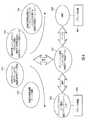
図2は、プロセス制御システムまたはプロセスプラント10(若しくはそのような他の産業用設備または環境)内で動作する例示的なプロセス制御メッセージネットワーク200のブロック図である。特に、プロセス制御メッセージネットワーク200は、ラップトップコンピュータ、タブレット及び手持ち式フィールドコミュニケータなどの様々な携帯型産業用演算装置112a〜112e、及びパーソナルコンピュータ及びワークステーションなどのさまざまな固定式産業用装置113a〜113cを含んでいてもよい。さまざまな産業用演算装置112a〜112e、113a〜113cは、1つまたは複数のバックボーン202、204、206を介して接続できる。各バックボーン202〜206は、プロセス制御システム内の異なるネットワークレベルに対応していてもよい。例えば、プラントネットワーク及び通信システム10は、プラントサイトに(または複数のプラントサイトまたはロケーションに)相互接続された通信ネットワークのセットをさらに含む。特に、図2に示すプラントネットワークは、トップレベルまたはビジネスネットワーク202、プラント管理ネットワーク203、及び1つまたは複数の制御ネットワーク206(そのうち1つのみ図2に示す)に接続されたプラントデバイスネットワーク204を含む。プラントネットワーク204及び制御ネットワーク206は、図1に示すフィールドデバイス15〜50をサポートするためのネットワーク105及びそれに接続されたサブネットワークであってもよいことが理解されよう。プロセス制御メッセージネットワーク200は、クラウド内などの外部の(プラントまたはその他の産業用設備の)サイトに位置していてもよい外部サーバネットワーク210を含むかまたはそれに接続されている。
FIG. 2 is a block diagram of an exemplary process
図2に示すように、ビジネスネットワーク202は、ビジネス、会計、企画などのアプリケーションを実装できるビジネスコンピュータ、ワークステーションまたはその他のビジネス固定式産業用演算装置113a〜113cのセットを含む。このネットワーク202は、ファイアウォールデバイス230を介して、外部サーバシステムまたはネットワーク210に接続されている。同様に、ビジネスネットワーク202は、ネットワーク間の中間的存在としての役割を果たすDMZデバイスまたはシステム240を介して、管理ネットワーク203とプラントネットワーク204とに接続されている。概して、ビジネスネットワーク202は、例えば、IEEE 802.3 Ethernet規格などの任意の好適な通信規格に準拠する通信リンク242に接続されたいくつかのワークステーション113a〜113cを含む。通常、ワークステーション113a〜113cは、Microsoft Corporation製のWindows(登録商標)などのネットワーク化機能を有するオペレーティングシステムを共有する。さまざまな組織的な役割を帯びたユーザはワークステーション113a〜113cを操作してプラント内の日常業務、例えば、プラント運用者の業務、プラントを管理するビジネスシステムなどを実行する。例えば、プラント運用者は技術者、会計士、マーケティングスタッフ、及びその他の要員を雇用できる。ワークステーション113a〜113cを操作するユーザは、通常であればそのユーザがプロセスプラントネットワーク204またはプロセス制御ネットワーク206アクセスすることを許可しない権限の一定のセットを有する。他方、上記ユーザはインターネット上のホストへはほぼ無制限にアクセスでき、その結果、ウィルス、マルウェア、ハイジャックの試み、及びその他のサイバー脅威に晒される危険が比較的高い。
As shown in FIG. 2, the
同様に、管理ネットワーク203は、例えば、IEEE 802.3 Ethernet規格などの任意の好適な通信規格に準拠する通信リンク244を介して接続されたさまざまなコンピュータまたはワークステーションを含む。パーソナルコンピュータ、ワークステーション、または図2でワークステーション246として描かれたその他の固定式産業用演算装置の1つ以上は、プラント内のさまざまな携帯型産業用演算装置のためのローカルコンテンツを格納するローカルコンテンツリポジトリ247を含むかまたはそれに接続されている。同様に、管理ネットワーク203は、1つまたは複数の携帯型産業用演算装置112a〜112c(各々が無線インターフェースを有する)が無線でネットワーク203に接続し、したがって、ワークステーション246に接続して大規模ファイル転送、メッセージなどを実行するための、無線アクセスポイントなどの1つまたは複数のプロセス制御メッセージネットワークアクセスポイント208aを含んでいてもよい。これについては本明細書内で詳述する。
Similarly, the
同様に、図1のネットワーク100であってもよいプラントネットワーク204は、さまざまなコンピュータまたはワークステーション260、データヒストリアン262などを含む。これらは、IEEE 802.3 Ethernetプロトコルなどの任意の好適な通信規格に準拠する通信リンク264を介して接続された固定式資産またはデバイスの例である。ネットワーク204は、ファイアウォールまたはコントローラでもよいアクセスポイント266を介して、例えば、プロセス制御ネットワーク206に接続されている。概して、ワークステーション260は、プロセスまたは制御オペレータがプロセス制御ネットワーク206(コントローラ、フィールドデバイスなどの)内のデバイスの進行中の動作を表示し制御してプラントまたはオンライン制御動作を実行するためのオペレータワークステーションであってもよい。上記ワークステーション260は、オペレータ及び保守要員などの要員がフィールドデバイス、及び回転装置、振動装置、発電装置などのその他のタイプの資産を含む制御資産のさまざまな分析を実行するたまのさまざまな異なるアプリケーションを含み、実行することができる。図2に示すように、ワークステーション268として示す固定式産業用演算装置の1つ以上は、プラント内のさまざまな携帯型産業用演算装置112d〜112fのためのローカルコンテンツを格納するローカルコンテンツリポジトリ270を含むかそれに接続されたフリート管理ステーションとして動作できる。所望であれば、ワークステーション268は、さまざまな固定式産業用演算装置のためのローカルコンテンツを管理でき、ローカルコンテンツリポジトリ270がさらに、またはそれに代わって前記コンテンツを格納できる。同様に、プラントネットワーク204は、1つまたは複数の携帯型産業用演算装置112d〜112f(各々が無線通信インターフェースを有する)が無線でネットワーク204に接続し、したがって、ワークステーション268に接続して大規模ファイル転送、メッセージなどを実行するための、無線アクセスポイントなどの1つまたは複数のプロセス制御メッセージネットワークアクセスポイント208bを含んでいてもよい。これについては本明細書内で詳述する。
携帯型産業用演算装置112a〜112fは、同じタイプの複数のデバイス(例えば、フィールドコミュニケータ、オシロスコープ、電流計)を含んでいてもよく、また、異なるタイプのデバイスと異なる製造業者によるデバイスまたは異なる機能を有するデバイスを含んでいてもよい。
Similarly, the
The portable
制御ネットワーク206は、コントローラ、入出力(I/O)デバイス、及びHART、FOUNDATION(登録商標)Fieldbus、Profibus、CANなどのネットワークを含む自社所有またはプロセス制御ネットワークを介して接続されたフィールドデバイスなどのさまざまな制御デバイス及びサブネットワークを含んでいてもよいことが理解されよう。上記ネットワークは任意の所望のプロセス制御プロトコルを使用できる。概して、携帯型産業用演算装置112a〜112fを用いて、これらのデバイス及び/またはサブネットワークについて保守、点検、修理、テスト及び環境設定活動を行うことができる。同様に、プラントまたはその他の産業用設備は、振動分析及び監視デバイス、回転装置、発電装置などの、プラントに配置された他のタイプのデバイスを含んでいてもよい。これらは図2には示していないが、1つまたは複数の携帯型産業用演算装置112a〜112fを用いて、稼働、保守、設置、修理、テスト、キャリブレーションなどが可能である。
The
さらに、プロセス制御メッセージアクセスポイント208a〜208cの組み合わせを各ネットワーク202〜206上に分散して、産業用演算装置112a〜112e、113a〜113c、246、268間の直接または間接の接続機能を実現し、プロセス制御メッセージネットワーク200にアクセスし(すなわち、そこに登録及び/または記載し)、次いで、プロセス制御メッセージサービスにアクセスできる。概して、これらのアクセスポイント208a〜208cは少なくともアクセスポイント55a、55b及び無線ゲートウェイ35とは論理的に別々であり、いくつかの実施例では、アクセスポイント55a、55b及び無線ゲートウェイ35とは論理的にも物理的にも別々である。言い換えれば、いくつかの実施例では、アクセスポイント208a〜208cは同じハードウェアをアクセスポイント55a、55b及び無線ゲートウェイ35として使用できるが、別の実施例では、アクセスポイント208a〜208cは、アクセスポイント55a、55b及び/または無線ゲートウェイ35とは別々の専用のハードウェアを有する。図1と同様に、図2はネットワークバックボーン202〜206に接続されたデバイスのうち単一のデバイスのみを示しているが、デバイスの各々はネットワークバックボーン202〜206上の複数のインスタンスを有していてもよいことが理解されよう。実際、プロセスプラント10は、各ネットワークレベルの複数のネットワークバックボーン202〜206を含んでいてもよい。
Further, a combination of process control
DMZ層またはデバイス240は、プロセス制御層またはネットワーク204及び206とプラントまたは産業用設備デバイスネットワークと管理ネットワーク203とをインターネットまたはビジネスLANネットワーク202及び外部ネットワーク210などのその他の外部ネットワークまたは公共ネットワークから分離するように動作する。図2の例示の通信システム10では、プラントLAN層またはビジネスネットワーク202は、ルータ/ファイアウォール230を介して、インターネットまたはその他の公共ネットワークに接続され、プラントDMZ層240は、DMZ240の一部として、ルータ/ファイアウォールを介して、プラント層またはビジネスネットワーク200に接続されている。
The DMZ layer or
プラントDMZ240は、アンチウィルスサーバ、データサーバ、及びヒストリアンサーバなどのいくつかのサーバを含んでいてもよい。公知のように、DMZ層240は、概して、インターネットなどの大規模なネットワークへの直接の露出をいくつかのホスト(すなわち、アンチウィルスサーバ、データサーバ、及びヒストリアンサーバ、DNSサーバ、ウェブサーバなど)に制限することで、ネットワーク203、204、及び206などのローカルまたはプラントネットワークへの追加的のセキュリティを提供する。なお、DMZ層またはデバイス240は、概して、セキュリティ機能を実装して通信を安全にする1つまたは複数のホストを介してすべての着信及び発信インターネットトラフィックを誘導することでシステム203、204、及び206のセキュリティを改善する任意のネットワーク層であってもよい。プロセス制御システムまたはプロセスプラント10内のプロセス制御メッセージネットワーク200に加えて、プロセス制御メッセージネットワーク200は、プロセス制御システム10の外部のコンピューティングクラウドまたはその他の外部システム210に通信可能に接続されていてもよく、ここで外部システム210は専用のサーバ212を含めて専用のITシステム、インフラストラクチャなどを含む。いくつかの実施例では、外部システム210は、プロセス制御システム10に、第3の部分として、格納、分析及び/または更新サービスを提供できる。例えば、外部システム210は、個々の産業用演算装置112a〜112e、113a〜113c、246、268からの特定のフィールドデバイス15〜52の環境設定、診断などの情報のアップロード、産業用演算装置112a〜112e、113a〜113c、246、268または個々の産業用演算装置へのコンテンツの一括ダウンロード、使用許諾管理などを含む、プロセス制御システム10の環境設定情報を維持できる。
The
さらに、図2の外部システム210は、例えば、概して協働してさまざまな産業用演算装置112a〜112e、113a〜113c、246、268にダウンロードすべきコンテンツを決定するエンドユーザリポジトリ290、ノーティファイア292、コンテンツ決定装置294、及びコンテンツダウンローダ296などのさまざまなシステム及びコンポーネントを含む。システム210は、さらに、1つまたは複数のビジネスシステムまたはコンピュータ299を含んでいてもよい。ビジネスシステム299を用いて、携帯型装置112a〜112e、113a〜113c、246、248の1つ以上のための新しいコンテンツを購入または獲得することができ、ビジネスシステム299は、そのような購入または使用許諾の表示をライセンスキー、コードなどの形式で提供できる。同様に、さまざまなファイアウォール並びにDMZデバイス230及び240は、産業用演算装置と外部ネットワーク210内のコンポーネントとの間の安全な通信を可能にするプログラミングまたは環境設定を含む。例えば、ワークステーション246及び268は、これらのデバイスがDMZ並びにファイアウォールデバイス230及び240をナビゲートしてこれらのデバイスを通して外部ネットワーク210へ安全な方法で通信することを可能にする通信ソフトウェアを含む。
In addition, the
より具体的には、携帯型産業用演算装置112a〜112eは、フィールドコミュニケータ、キャリブレーション装置、及び、産業用プラント、プロセスプラント、油井、ポンピングステーションなどの産業用設備内で使用されるその他のタイプの携帯型装置を含んでいてもよく、プロセス測定装置、バルブ、ポジショナなどのフィールドデバイス、並びに、回転装置(タービンなど)、発電装置、振動分析及び検出装置などの産業用設備内で使用されるその他のタイプのデバイスまたは資産について、環境設定、トラブルシューティング、キャリブレーション、及びその他の動作を実行することができる。異なるタイプ及びブランドの産業用携帯型装置が同じかまたは異なる製造業者によって製造されていてもよく、さまざまな携帯型産業用演算装置112a〜112eが異なる特徴及び機能を有していてもよいことは言うまでもない。例えば、携帯型産業用演算装置112a〜112eのいくつかは、プラント内のさまざまなサブネットワーク206の1つ以上で通信し、HARTまたはFieldbusフィールドデバイスなどのフィールドデバイスと通信するフィールドコミュニケータであってもよい。携帯型産業用演算装置112a〜112eのいくつかは、回転装置、振動分析装置などのフィールドデバイス及びその他のタイプのデバイスを含むプラント内デバイスをキャリブレーションまたは環境設定するキャリブレーション装置または環境設定装置であってもよい。携帯型産業用演算装置112a〜112eのいくつかは、電源装置などのプラント内の配線及びその他のデバイスをテストするための電流計、電圧計、抵抗計、電気インピーダンス計、またはマルチメータなどの、電気的テスト機能であるかそれを含んでいてもよい。同様に、携帯型産業用演算装置112a〜112eのいくつかは本質的に安全であり、危険な環境で使用できる。携帯型産業用演算装置112a〜112eのいくつかはさまざまな製造業者によって製造された特別に環境設定された携帯型装置であってもよく、或いは、ラップトップ、電話機、パーソナルデジタルアシスタント(PDA)、タブレットコンピュータなどの汎用コンピュータ上に実装された、または接続されたソフトウェア機能またはハードウェアとして実装されていてもよい。携帯型産業用演算装置112a〜112eは、例えば、機能性、使用法、タイプ、製造業者、ユーザなど、または上記またはその他の特性の組み合わせに基づいて、任意の方法で携帯型装置の1つまたは複数のフリートにグループ化でき、例えば、フリート管理ステーションとしてのワークステーション246、268の1つを用いてグループ化してもよい。標準のITセキュリティ機構(例えば、ユーザ認証、アクティブディレクトリなど)よりも高度の追加のセキュリティを提供するために、プロセス制御メッセージネットワーク200は、外部クラウド210などの外部ネットワーク間のネットワーク分離を維持し、エンドユーザのサイト(例えば、プラント)の内部通信ネットワークは、通常、ビジネスネットワーク202、プラントネットワーク204、制御ネットワーク206などの複数の分離ネットワークを含む。ネットワーク間の中間的存在またはDMZデバイス240は、プラント内の既存のルータ上で稼働するソフトウェアを実行して上記ネットワークを相互接続する。一例では、DMZソフトウェアはネットワーク分離を保持するポート転送を実装するが、プラントネットワーク上のコンピュータまたは産業用装置が外部クラウドネットワーク210を含むその他のネットワークへの安全なアクセスができるようにする。したがって、プロセス制御メッセージネットワーク200はプロセス制御ネットワーク100とほぼ同じかまたは同様のハードウェアを含んでいてもよい一方で、プロセス制御メッセージネットワーク200はプロセス制御ネットワーク100とは論理的に別々のままである。同時に、複数の分離ネットワーク及びプロセス制御メッセージサービスの間に分散したプロセス制御メッセージアクセスポイント208a〜208cによって、複数の分離ネットワークにまたがった通信が可能である。本明細書で言うところの、ネットワーク202、203、204、206及びそれに接続されたデバイスはすべて、第1のまたは第2のロケーションと呼ばれる同じ一般的なロケーションにあると考えることができ、またはこれらのネットワーク及びデバイスは異なるロケーションにあると考えることもできる。
More specifically, portable
さらに、フリート管理ステーション246及び268は、この例では、エンドユーザのサイトまたはプラント内に位置する関連付けられたフリート管理ソフトウェアを有するコンピュータまたはワークステーションである。上記デバイスは、例えば、プライント内の携帯型産業用演算装置の識別されたフリートの各々を管理するために、プラントまたはフリートアドミニストレータによってユーザインターフェースとして使用される。より具体的には、上記コンピュータは、携帯型(または固定式)デバイスフリートアドミニストレータが、産業用携帯型装置112a〜112fのフリート又と、所望であれば固定式装置のフリート内のコンテンツを自動的または半自動的に管理するのに連携して一部または全部のアクティビティを実行するために使用される。同様に、ローカルコンテンツリポジトリ247及び270は、エンドユーザのサイトにある携帯型産業用演算装置112a〜112f(及び所望であれば固定式装置)のためのコンテンツを、前記コンテンツがさまざまな携帯型産業用演算装置112a〜112fまたは固定式装置113a〜113cへダウンロードされる前または後に、ローカルに格納するデータベースである。
Further,
ただし、図2に示すような少なくとも1つの実施例では、プラントネットワークの外部の外部クラウドまたはサーバシステム(ITシステム、インフラストラクチャなど)は、外部クラウド内のITインフラストラクチャ(サーバ、プロセッサなど)の上で概して稼働していくつかの異なる入力判定基準を評価し、特定のカスタマーサイトにおける特定の産業用携帯型装置(または特定の固定式装置というコンテンツ)が有するかまたは使用する資格があるフィルタリングされた/標的にされたコンテンツが何であるかを決定するソフトウェア機構であるコンテンツ決定装置294を含む。概して、コンテンツ決定装置294は、特徴、プログラミング、オペレーティングシステム、更新などを詳述する入力(それらはすべてコンテンツと呼ばれる)と、産業用携帯型装置112a〜112fまたは固定式装置のための環境設定パラメータを示す環境設定情報とを格納または受信し、産業用携帯型装置または固定式装置のフリート内の各産業用装置がどのコンテンツを有することができるかを決定する。さらに、コンテンツダウンローダ296はコンテンツ決定装置294に接続され、コンテンツ決定装置294の指定に従って、産業用携帯型装置または固定式装置が使用されるかまたは位置するプラントの外部及び内部ネットワークを介して、コンテンツを産業用装置にダウンロードするための効率的で安全な接続を提供する。
However, in at least one embodiment as shown in FIG. 2, the external cloud or server system (IT system, infrastructure, etc.) outside the plant network is above the IT infrastructure (server, processor, etc.) in the external cloud. In general, run a number of different input criteria to evaluate and filtered a specific industrial portable device (or a specific fixed device content) at or at a specific customer site / Includes a
さらに、ソースコンテンツリポジトリ298は、産業用携帯型装置112a〜112f(または所望なら固定式装置)へのダウンロードに利用可能なすべてのコンテンツを格納し、プラント内の産業用携帯型装置112a〜112f(または固定式装置)にダウンロードすべき時には、そのコンテンツをコンテンツダウンローダ296に提供する。ノーティファイア292は、コンテンツ決定装置294が、新しいコンテンツがビジネスシステムコンピュータ299の1つを用いて入手された(例えば、使用許諾を受けた、または購入された)時など、特定の産業用装置でコンテンツが利用可能になったか前記デバイスにダウンロードする決定がなされた時にユーザに通知を送信するモジュール(例えば、プロセッサ上で実行されるソフトウェア)である。概して、ビジネスシステムコンピュータ299は、新しいコンテンツを獲得するために使用できるユーザカウント及び認証、購入、注文管理システム、アプリケーションまたはフィーチャストアなどを含む。そして、エンドユーザ情報リポジトリ290は、産業用携帯型装置112a〜112fのフリート内の各産業用携帯型装置上及び/またはプラントまたはその他の産業用設備のフリート内の固定式装置のセット上のコンテンツの現在のリスト及びそのようなコンテンツのバージョンに関するエンドユーザ情報を収集し格納するデータベース及び通信モジュールである。
In addition, the
図3は、プロセス制御メッセージシステムアーキテクチャ300を用いる産業用演算装置112、113間のような、要求元エンドポイント(RequestEndpoint)と応答側エンドポイント(ResponseEndpoint)との間の例示的なやりとりのブロック図である。一例では、ファイアウォール230及び/またはDMZ240はエンドポイントとして動作し、より具体的には、要求元エンドポイントからのメッセージをネットワークを介して応答側エンドポイントへ転送する中間エンドポイントとして動作する。上記のように、DMZソフトウェアは、ネットワーク分離を保持するポート転送を実装するが、産業用演算装置が他のネットワークにアクセスして他の産業用演算装置または外部ネットワークと通信することは許可する。したがって、要求元エンドポイントは、他のネットワーク内の応答側エンドポイントを指定する要求内の情報で、ファイアウォールまたはDMZをエンドポイントとして指定できる。ファイアウォールまたはDMZは、メッセージを受信でき、セキュリティソフトウェアを用いて、ポート転送を用いて応答側エンドポイントへ転送するメッセージを分析し、かつ/または無効にすることができる。
FIG. 3 is a block diagram of an exemplary interaction between a requesting endpoint (RequestEndpoint) and a responding endpoint (ResponseEndpoint), such as between the
各エンドポイントは、プラットフォームとアプリケーションとを含む。やりとりは、登録、名簿への掲載、及びプロセス制御メッセージサービスへの参加に分類できる。なお、以下の説明から、プロセス制御メッセージシステムアーキテクチャ300は、プラットフォームから独立しており、これに限定されないが、他の産業用装置コンピューティングプラットフォーム(例えば、Windows XP、Windows Embedded Compact 2013、Windows 10などのオペレーティングシステム及びインターフェース)及びフィールドデバイス通信プラットフォーム(例えば、Fieldbus、HARTなど)を含むさまざまなプラットフォーム間の通信を可能にする。
Each endpoint includes a platform and an application. Interactions can be categorized as registration, listing, and participation in the process control message service. Note that, from the following description, the process control
さらに、プロセス制御メッセージシステムアーキテクチャ300は、物理層での、最良のプロトコル適合に基づいて特定のアプリケーションについてトランスポートタイプ/プロトコルからの独立(例えば、WiFi、ユニバーサルシリアルバス(USB)など)を指定することを可能にする。例えば、プロセス制御メッセージシステムアーキテクチャ300を用いる携帯型産業用演算装置112aは、無線アクセスポイント208aを介してプロセス制御メッセージサービスに接続する時には、WiFiトランスポートタイプを指定できる一方で、携帯型産業用演算装置112aはUSB接続を介してパーソナルコンピュータ112bに接続する時には、USBトランスポートタイプを指定できる。
Furthermore, the process control
特に、プロセス制御メッセージシステムアーキテクチャ300は、個々の産業用演算装置112、113とサーバ150などの中央コンピュータ上に配備されたコンポーネント及びサービスを含む。プロセス制御メッセージシステムアーキテクチャ300のコンポーネント及びサービスは、標準のITインフラストラクチャ及びサービス(例えば、TCP/IP、認証、アクティブディレクトリ)よりも高度の、特にプロセス制御ネットワークのトランスポート層よりも上位の専用の通信プロトコルを有する抽象化層として表される。したがって、トランスポート層がプロセス制御ネットワークに対応するネットワーク通信プロトコル(例えば、TCP/IP)を有する場合、プロセス制御メッセージサービスの通信プロトコルはネットワーク通信プロトコルのよりも上位の層を形成する。
In particular, the process control
プロセス制御メッセージシステムアーキテクチャ300は、プロセス制御メッセージサービスの通信プロトコルより上位の層を形成するプロセス制御通信プロトコル(例えば、Fieldbus、HARTなど)をさらに含む。したがって、要求元産業用演算装置は、別の産業用演算装置、フィールドデバイスなどの宛先デバイスの通信プロトコルを指定できる。
The process control
概して、プロセス制御メッセージシステムアーキテクチャ300は、プラントインフラストラクチャ内で無線または有線接続を介して接続されたマシンプラットフォーム間の要求−応答及び大規模データ転送動作を容易にする。プロセス制御メッセージシステムアーキテクチャ300は、外部ネットワークまたはクラウド210内のサービス間、及びプロセス制御メッセージネットワーク200に接続されたプラットフォーム(例えば、マルチプラットフォーム環境内でサービスを提供する記載されたプラットフォームを基本的に含む内部プラントサービス)間の情報交換など(例えば、産業用演算装置のための使用許諾及び更新サービス、ウェブサービス(例えば、ウェブエクステンダクライアント)など)及び、プラントまたはその他の産業用設備内のサービスのためのさまざまなアクティビティをサポートするように設計されている。各プラットフォームは、プラットフォームのシステム上にインストールされそこで稼働するプロセス制御メッセージアーキテクチャ(例えば、産業用演算装置)の複数のインスタンスを含んでいてもよい。他方、簡単な実装は、プロセス制御メッセージアーキテクチャの単一のインスタンスをインストールした1つの演算装置(例えば、固定式産業用演算装置)であり、これによって、1つの演算装置は、プラント10または外部ネットワーク210内のサービスへの接続ポイントとして容易にされる。
In general, the process control
要求−応答タイプの動作では、プロセス制御メッセージシステムアーキテクチャが、プラットフォームエンドポイントへの要求の送信と、要求内の指定のエンドポイントへの応答の送信によるアプリケーション−トピック応答とをサポートする。要求及び応答アクティビティは「RequestEndPoint」と「ResponseEndPoint」と呼ばれるエンドポイント間のデータ送受信を含む。RequestEndPointは、要求が送達される宛先であって応答の発信元/出所でもある。ResponseEndPointは応答が送達される宛先であって要求の発信元/出所でもある。RequestEndPoint及びResponseEndPointはプラットフォーム及びアプリケーションを含む。要求−応答エンドポイントは、トピック、アプリケーション及びプラットフォームから構成される。つまり、要求/応答動作は、クライアントが、プラットフォーム上で実行されているアプリケーションへ要求(トピック)を送信し、応答が返される動作を含む。トピックはプラットフォーム上で実行されているアプリケーション内にホスティングされる。トピックは、アプリケーションが実行すべきトピックを識別し、トピック名はアプリケーション名前空間内の全トピックにわたって一意的である。アプリケーションはトピックを受信しトピックを転送して処理に回すコンテナである。プラットフォームはアプリケーションをホスティングするプロセスを有する。したがって、特定のトピックに達するために、要求−応答メッセージはアプリケーション、プラットフォーム及び地ピック識別子を指定する。 In request-response type operations, the process control message system architecture supports sending requests to platform endpoints and application-topic responses by sending responses to specified endpoints in the request. Request and response activities include data transmission / reception between endpoints called “RequestEndPoint” and “ResponseEndPoint”. RequestEndPoint is the destination to which the request is delivered and the source / source of the response. The ResponseEndPoint is the destination to which the response is delivered and the source / source of the request. RequestEndPoint and ResponseEndPoint include a platform and an application. The request-response endpoint consists of topics, applications and platforms. That is, the request / response operation includes an operation in which the client sends a request (topic) to an application running on the platform, and a response is returned. Topics are hosted in applications running on the platform. The topic identifies the topic that the application should execute, and the topic name is unique across all topics in the application namespace. An application is a container that receives a topic, transfers the topic, and sends it to processing. The platform has a process for hosting applications. Thus, in order to reach a particular topic, the request-response message specifies the application, platform and ground pick identifier.
大規模データ転送(LDT)動作で、プロセス制御メッセージアーキテクチャはそれぞれ「LDTSource」、「LDTDestination」と呼ばれる送信元ロケーションから宛先へのファイルの転送をサポートする。LTDエンドポイントは、PlatformIDを含み、これは発信元プラットフォーム及び宛先プラットフォームを指定する。LDT発信元及び宛先は、ユニフォームリソースロケータ(URL)を含む。LDTSourceは特定のリソースを指定する一方で、LDTDestinationはロケーションのみを指定すれば良い。 With large data transfer (LDT) operations, the process control message architecture supports the transfer of files from the source location to the destination, referred to as “LDTSSource” and “LDTDDestination”, respectively. The LTD endpoint contains a PlatformID, which specifies the source platform and the destination platform. The LDT source and destination include a uniform resource locator (URL). While LDTSSource specifies a specific resource, LTDDestination need only specify a location.
要求/応答タイプの動作(例えば、インスタント/リアルタイムメッセージ、時間同期化)とLDT動作のいずれかで、要求はエンドポイント間のサービス品質を指定できる。例えば、要求は保証付きの送達を指定でき、それによってメッセージのコピーがデータベースまたはその他の発信元クライアントのストレージ内に一時的に記憶され、エンドポイントクライアントが受信の肯定応答によってメッセージを受信する能力を確保する。この時点で、メッセージのコピーはデータベースから消去される。他方、要求は保証付きの送達を指定しなくてもよく(または保証無しの送達を指定してもよく)、メッセージを記憶することなく、またエンドポイントがメッセージを受信する能力を確保することなく、要求を送信できる。いかなる動作も保証付きの、または保証無しの送達を利用できるが、概して、大規模データ転送はデータ転送サイズが理由で保証付きの送達を利用する一方で、リアルタイムまたはインスタントメッセージなどの要求/応答サービスは送達の即時性により関心があり、保証付きの送達を利用することを差し控える。 In either a request / response type operation (eg, instant / real-time message, time synchronization) or an LDT operation, the request can specify quality of service between endpoints. For example, a request can specify guaranteed delivery so that a copy of the message is temporarily stored in the database or other originating client's storage and the endpoint client has the ability to receive the message with an acknowledgment of receipt. Secure. At this point, the message copy is deleted from the database. On the other hand, the request may not specify guaranteed delivery (or may specify non-guaranteed delivery), without storing the message, and without ensuring the ability of the endpoint to receive the message. Can send a request. Any operation can use guaranteed or unguaranteed delivery, but generally large data transfers use guaranteed delivery because of data transfer size, while request / response services such as real-time or instant messaging Is more concerned with the immediate nature of delivery and refrains from using guaranteed delivery.
図4は、プロセス制御メッセージアーキテクチャ300と、アクセスポイント302、306と、参加デバイスまたはエンドポイント304、308と、プロセス制御メッセージサービス310〜316との関係の概略図である。プロセス制御メッセージネットワーク内の隅々のデバイスに分散されたプロセス制御メッセージシステムアーキテクチャ300を用いて、これに限定されないが、安全な通信、インスタント/リアルタイムメッセージ、ファイル転送、データ同期化、時間同期化、産業用演算装置プラットフォームの更新を含むさまざまなプロセス制御メッセージサービス310〜316をフィールドデバイス304、産業用演算装置、外部クラウド、パーソナルコンピュータ308などの間に提供できる。ただし、いかなるデバイスも、特に携帯型産業用演算装置112がプロセス制御メッセージサービスに参加してプロセス制御メッセージネットワーク内の他の産業用演算装置との通信、メッセージ、データ転送及びその他のやりとりを可能にするサービスを利用するには、産業用演算装置を、プロセス制御メッセージサービスに登録して記載しなければならない。
FIG. 4 is a schematic diagram of the relationship between process
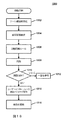
アプリケーションまたはサービスは、プロセス制御メッセージシステムアーキテクチャ300の公共インターフェース定義を用いて、さまざまなアクティビティを実行する。図5A及び5Bはプロセス制御メッセージシステムアーキテクチャ300内で定義されたプライマリ公共インターフェース及びベースクラスを示す図である。図5Aに示すように、例示的なインターフェース(IRequestSender)は、あるプラットフォームから別のプラットフォームへのアプリケーション−トピックに基づいて、定義されたメソッド(RequestSenderBase)の数またはクラスを用いて、要求を容易にする。RequestSenderBaseは、プロセス制御メッセージシステムアーキテクチャ300のレベル内で定義されるIRequestSenderインターフェースを実装する抽象クラスであり、プロセス制御メッセージシステムアーキテクチャ300のインフラストラクチャ(例えばメッセージ)を認識している。各要求発信元はベースクラスを継承している。
An application or service performs various activities using the public interface definition of the process control
この例では、定義されたメソッドは、これに限定されないが、BeginRequest、EndRequest、PauseRequest、ResumeRequest及びCancelRequestを含む。BeginRequestは、RequestEndPointへ送達すべきアプリケーション−トピックに基づいて要求を開始するために要求元クライアント(ResponseEndPoint)が呼び出す非同期メソッドである。BeginRequestメソッドは、要求の詳細と、動作の完了時に呼び出される非同期コールバックと、各々の特定の非同期動作要求を他の要求から区別するユーザ提供オブジェクトとを含む動作要求指定子である。BeginRequestメソッドは、その時点では保留状態であってもよい非同期動作を表すIAsyncOperationを返す。 In this example, the defined methods include, but are not limited to, BeginRequest, EndRequest, PauseRequest, ResumeRequest, and CancelRequest. BeginRequest is an asynchronous method that the requesting client (ResponseEndPoint) calls to initiate a request based on the application-topic to be delivered to RequestEndPoint. The BeginRequest method is an operation request specifier that includes request details, an asynchronous callback that is called upon completion of the operation, and a user-provided object that distinguishes each specific asynchronous operation request from other requests. The BeginRequest method returns an IAsyncOperation that represents an asynchronous operation that may be pending at that time.
EndRequestメソッドは、完了結果を読み出す要求の完了時に要求元クライアントが呼び出すメソッドである。EndRequestメソッドは、それ以外の時間には、保留状態の非同期動作が完了するのを待機し、非同期動作IAsyncOperationが開始した時にBeginRequestメソッドによって返される完了対象の保留状態の非同期要求への参照を使用する。EndRequestメソッドは、さらに、非同期動作の結果を返す。PauseRequestメソッドは、指定された非同期動作を休止させるために要求元クライアントが呼び出すメソッドである。PauseRequestメソッドは、非同期動作IAsyncOperationが開始した時にBeginRequestメソッドによって返される休止対象の保留状態の非同期要求への参照を使用する。ResumeRequestメソッドは、休止状態の指定された非同期動作を再開するためにクライアントエンドポイントが呼び出すメソッドである。ResumeRequestメソッドも、同様に、非同期動作IAsyncOperationが開始した時にBeginRequestメソッドによって返される再開対象の保留状態の非同期要求への参照を使用する。Cancel Requestメソッドは、指定された非同期動作を取り消すために要求元クライアントが呼び出すメソッドであり、非同期動作IAsyncOperationが開始した時にBeginRequestメソッドによって返される取り消し対象の保留状態の非同期要求への参照を使用する。 The EndRequest method is a method that is called by the requesting client when a request for reading a completion result is completed. At other times, the EndRequest method waits for the pending asynchronous operation to complete and uses the reference to the pending asynchronous request to be completed returned by the BeginRequest method when the asynchronous operation IAsyncOperation is started. . The EndRequest method further returns the result of the asynchronous operation. The PauseRequest method is a method that is called by a requesting client in order to pause a specified asynchronous operation. The PauseRequest method uses a reference to a paused pending asynchronous request returned by the BeginRequest method when the asynchronous operation IAsyncOperation is started. The ResumeRequest method is a method that the client endpoint calls to resume the designated asynchronous operation in the dormant state. Similarly, the ResumeRequest method uses a reference to the resume request to be resumed to be resumed returned by the BeginRequest method when the asynchronous operation IAsyncOperation is started. The Cancel Request method is a method called by a requesting client to cancel a specified asynchronous operation, and uses a reference to a pending asynchronous request to be canceled that is returned by the BeginRequest method when the asynchronous operation IAsyncOperation is started.
図5Bに示すように、例示的なインターフェース(RequestReceiver)は、あるプラットフォームから別のプラットフォームへのアプリケーション−トピックに基づいて、定義されたメソッド(RequestReceiverBase)の数またはクラスを用いて、応答を処理する。RequestReceiverBaseは、RequestReceiverインターフェースメソッドを定義または実装する抽象クラスで、プロセス制御メッセージシステムアーキテクチャ300のレベル内で定義され、プロセス制御メッセージシステムアーキテクチャ300のインフラストラクチャ(例えばメッセージ)を認識している。各要求受信側はベースクラスを継承し、抽象メソッドを実装する。
As shown in FIG. 5B, an exemplary interface (RequestReceiver) processes a response using a defined number of methods (RequestReceiverBase) or class based on application-topic from one platform to another. . RequestReceiverBase is an abstract class that defines or implements the RequestReceiver interface method, is defined within the level of the process control
この例では、定義されたメソッドは、これに限定されないが、ProcessRequest、ProcessPausing、ProcessResuming、ProcessCancellation、SendResponse及びNotifyStateChangedを含む。ProcessRequestは、アプリケーション−トピックに基づいて着信する要求を処理するために受信側クライアント(RequestEndPoint)が呼び出す抽象メソッド(すなわち、宣言されたが実装を含まず−インスタンス化できない−サブクラスに実装を提供するよう要求するメソッド)である。ProcessRequestメソッドは、IRequestSender.BeginRequestメソッドからの動作要求指定子AsyncOperationを使用し、動作が完了するとSendResponseメソッドを呼び出す。ProcessPausingメソッドは、IRequestSender.PauseRequestメソッドからの着信する動作休止要求を処理するために受信側クライアントが呼び出す抽象メソッドである。ProcessPausingメソッドは、IRequestSender.BeginRequestメソッドからの動作要求指定子IAsyncOperationを使用して動作の休止を指定する。ProcessResumingメソッドは、IRequestSender.ResumeRequestメソッドからの着信する動作再開要求を処理するために受信側クライアントが呼び出す抽象メソッドである。ProcessResumingメソッドは、IRequestSender.BeginRequestメソッドからの動作要求指定子IAsyncOperationを使用して動作の再開を指定する。ProcessCancellationメソッドは、IRequestSender.CancelRequestメソッドからの着信する動作取り消し要求を処理するために受信側エンドポイントが呼び出す抽象メソッドである。ProcessCancellationメソッドは、IRequestSender.BeginRequestメソッドからの動作要求指定子IAsynchOperationを使用して動作の取り消しを指定する。ProcessCancellationメソッドは、動作取り消し時にSendResponseメソッドを呼び出すことができる。SendResponseメソッドは、IRequestSender.BeginRequestメソッドからの要求指定子内に指定されたResponseEndPointへの応答を送信するために受信側クライアントが呼び出す抽象メソッドである。SendResponseメソッドは、要求指定子識別と、動作ステータスと動作結果とを応答の一部として使用する。NotifyStateChangedメソッドは、IRequestSender.BeginRequestメソッドからの要求指定子IAsynchOperation内に指定されたResponseEndPointへ状態変化を送信するために受信側クライアントが呼び出す抽象メソッドである。 In this example, defined methods include, but are not limited to, ProcessRequest, ProcessPausing, ProcessResuming, ProcessCancellation, SendResponse, and NotifyStateChanged. ProcessRequest is an abstract method (ie, declared but not implemented-cannot be instantiated) that is called by the receiving client (RequestEndPoint) to handle incoming requests based on the application-topic. Request method). The ProcessRequest method is an IRequestSender. The operation request specifier AsyncOperation from the BeginRequest method is used, and when the operation is completed, the SendResponse method is called. The ProcessPausing method is an IRequestSender. This is an abstract method that is called by the receiving client in order to process an incoming suspension request from the PauseRequest method. The ProcessPausing method is an IRequestSender. The operation is stopped using the operation request specifier IAsyncOperation from the BeginRequest method. The ProcessResuming method is an IRequestSender. This is an abstract method that is called by the receiving client in order to process an incoming operation resumption request from the ResumeRequest method. The ProcessResuming method is an IRequestSender. Use the operation request specifier IAsyncOperation from the BeginRequest method to specify the resumption of the operation. The ProcessCancellation method is an IRequestSender. This is an abstract method that the receiving endpoint calls to process an incoming operation cancellation request from the CancelRequest method. The ProcessCancellation method is an IRequestSender. Specify the cancellation of the operation using the operation request specifier IAsyncOperation from the BeginRequest method. The ProcessCancelation method can call the SendResponse method when canceling the operation. The SendResponse method is an IRequestSender. This is an abstract method that the receiving client calls to send a response to the ResponseEndPoint specified in the request specifier from the BeginRequest method. The SendResponse method uses the request specifier identification, the operation status, and the operation result as part of the response. The NotifyStateChanged method is an IRequestSender. This is an abstract method that the receiving client calls to send a state change to the ResponseEndPoint specified in the request specifier IAsyncOperation from the BeginRequest method.
再度図5Aを参照すると例示的なインターフェース(ILargeDataTransfer)は、定義されたメソッドTransferRequestSender)の数またはクラスを用いて、あるプラットフォームから別のプラットフォームへの大規模データ転送を容易にする。TransferRequestSenderは、インターフェースILargeDataTransferを実装し、プロセス制御メッセージシステムアーキテクチャ300のレベル内で定義される。インターフェースILargeDataTransferを用いて、大規模データ転送動作のインスタンス化が可能になる。
Referring again to FIG. 5A, an exemplary interface (ILlargeDataTransfer) uses a defined number of methods TransferRequestSender or class to facilitate large-scale data transfer from one platform to another. TransferRequestSender implements the interface ILARGEDataTransfer and is defined within the level of the process control
この例では、定義されたメソッドは、これに限定されないが、BeginTransfer、EndTransfer、Pause、Resume及びCancelを含む。BeginTransferは、大規模データ転送動作を開始するために要求元クライアント(ResponseEndPoint)が呼び出す非同期メソッドである。BeginTransferメソッドは、大規模データ転送動作の詳細を含む動作転送指定子と、大規模データ転送動作の完了時に呼び出される非同期コールバックと、各々の特定の非同期大規模データ転送動作要求を他の大規模データ転送要求から区別するユーザ提供オブジェクトとを使用する。BeginTransferメソッドは、その時点では保留状態であってもよい大規模データ転送の非同期動作を表すIAsyncResultを返す。 In this example, defined methods include, but are not limited to, BeginTransfer, EndTransfer, Pause, Resume, and Cancel. BeginTransfer is an asynchronous method that is called by a requesting client (ResponseEndPoint) to start a large-scale data transfer operation. The BeginTransfer method includes an operation transfer specifier that includes details of a large-scale data transfer operation, an asynchronous callback that is called upon completion of the large-scale data transfer operation, and each specific asynchronous large-scale data transfer operation request to another large-scale data transfer operation. Use user-provided objects to distinguish from data transfer requests. The BeginTransfer method returns an IAsyncResult that represents an asynchronous operation of large-scale data transfer that may be pending at that time.
EndTransferメソッドは、大規模データ転送の完了時に完了結果を読み出すために要求元クライアントが呼び出すメソッドである。EndTransferメソッドは、それ以外の時間には、保留状態の非同期大規模転送動作が完了するのを待機し、非同期動作IAsyncResultが開始した時にBeginTransferメソッドによって返される完了対象の保留状態の非同期大規模データ転送要求への参照を使用する。EndTransferメソッドは、さらに、大規模データ転送動作結果を返す。Pauseメソッドは、指定された非同期大規模データ転送動作を休止させるために要求元クライアントが呼び出すメソッドである。Pauseメソッドは、非同期大規模データ転送動作IAsyncResultが開始した時にBeginTransferメソッドによって返される休止対象の保留状態の非同期要求への参照を使用する。Resumeメソッドは、休止状態の指定された非同期大規模データ転送動作を再開させるために要求元クライアントエンドポイントが呼び出すメソッドである。Resumeメソッドも、同様に、非同期大規模データ転送動作IAsyncResultが開始した時にBeginTransferメソッドによって返される再開対象の保留状態の非同期大規模データ転送要求への参照を使用する。Cancelメソッドは、指定された非同期大規模データ転送動作を取り消すために要求元クライアントが呼び出すメソッドであり、非同期大規模データ転送動作IAsyncResultが開始した時にBeginTransfertメソッドによって返される取り消し対象の保留状態の非同期要求への参照を使用する The EndTransfer method is a method that is called by the requesting client to read the completion result when the large-scale data transfer is completed. At other times, the EndTransfer method waits for the asynchronous large-scale transfer operation in the pending state to complete, and when the asynchronous operation IAsyncResult starts, the asynchronous large-scale data transfer in the pending state to be returned returned by the BeginTransfer method Use a reference to the request. The EndTransfer method further returns a large-scale data transfer operation result. The Pause method is a method that is called by a requesting client in order to pause a specified asynchronous large-scale data transfer operation. The Pause method uses a reference to a suspended asynchronous request to be paused returned by the BeginTransfer method when the asynchronous large-scale data transfer operation IAsyncResult is started. The Resume method is a method that is called by the requesting client endpoint in order to resume the designated asynchronous large-scale data transfer operation in the dormant state. Similarly, the Resume method uses a reference to the resumed pending asynchronous large-scale data transfer request returned by the BeginTransfer method when the asynchronous large-scale data transfer operation IAsyncResult is started. The Cancel method is a method that is called by the requesting client to cancel the specified asynchronous large-scale data transfer operation. When the asynchronous large-scale data transfer operation IAsyncResult is started, the canceled asynchronous request to be canceled returned by the BeginTransfer method. Use a reference to
以下に、大規模データ転送を作成し、インスタンス化し開始するプロセス制御メッセージシステムアーキテクチャ300の一例を示す。
LargeDataTransferSpecifierBuilderを用いて大規模データ転送を作成する:
var specifier = LargeDataTransferSpecifierBuilder.Build(filePath,
destinationPlatform);
TransferRequestSenderをインスタンス化する:
var ldtSender = new TransferRequestSender(localEndPont, new ServerFactory());
転送を開始する:
var operation = ldtSender.BeginTransfer(specifier、ar => { }, null, true);
operation.StateChanged +=(s、e)=> Console.WriteLine(e.State);
var result = ldtSender.EndTransfer(operation);
Console.WriteLine(("LDT operation result: {0}", result.Status.IsSuccessful);
The following is an example of a process control
Create a large data transfer using the LargeDataTransferSpecifierBuilder:
var specifier = LargeDataTransferSpecifierBuilder. Build (filePath,
destinationPlatform);
Instantiate TransferRequestSender:
var ldtSender = new TransferRequestSender (localEndPont, new ServerFactory ());
Start the transfer:
var operation = ldtSender. BeginTransfer (specifier, ar => {}, null, true);
operation. StateChanged + = (s, e) => Console. WriteLine (e.State);
var result = ldtSender. EndTransfer (operation);
Conole. WriteLine (("LDT operation result: {0}", result.Status.IsSuccessful);
図6は、プロセス制御メッセージシステムアーキテクチャ300によって実装される共通インターフェースの一例を示す図である。図6から分かるように、共通インターフェースは、これに限定されないが、Topic、TopicData、Status、UserContext、IAsyncOperation、AsyncOperationStateChangedEventArgs及びAsyncOperationStateを含む。Topicインターフェースは、トピック識別子を表すクラスであり、Topic<string>として使用される。TopicDataインターフェースは、トピックデータを表すクラスである。Statusインターフェースは、例えば、メッセージの送達を保証する(または保証しない)ために応答内で使用されるステータスオブジェクトである。UserContextインターフェースは、ユーザコンテキスト情報を含むクラスである。UserContextインターフェースは、UserContextを別のコンテキストと比較し、それらのコンテキストが同一の場合にtrueを返す定義されたメソッドIsEqual(UserContext)をさらに実装する。IAsyncOperationインターフェースは、非同期動作を表し、非同期動作状態が変更されると発生する非同期動作状態変化通知の1つのイベントStateChanged<AsyncOperationStateChangedEventArgs>を提供する。次いで、AsyncOperationStateChangedEventArgsは、非同期動作状態変化の引数のクラスである。AsynchOperationStateは、非同期動作識別の特性(OperationID)、非同期動作のタイプ(Type)、及び非同期動作の進捗値(Progress)を備えた非同期動作状態情報を提供する。
FIG. 6 is a diagram illustrating an example of a common interface implemented by the process control
図1に関して分かるように、いくつかの実施例では、サーバ150は、産業用演算装置112、113をプロセス制御メッセージサービス内に登録し記載するためのエンロールメントサーバとしての役割を果たすことができる。プロセス制御メッセージサービスのアドミニストレータは各産業用演算装置を登録できる。例えば、新たに使用許諾を受けた産業用演算装置112、113をプロセス制御メッセージネットワークに追加し、その時に、産業用演算装置に関連付けられた一意的な識別子を用いて登録できる。この時、登録は、これに限定されないが、プロセス制御メッセージネットワーク上で前記産業用演算装置が通信する可能性がある他のデバイスへの申し込み、特定のプロセス制御メッセージサービスの制限などを含む、産業用演算装置についての制限または権限付与を定義できる。さらに、ゲスト産業用演算装置(例えば、外部契約によって使用される、またはプロセス制御システム内で稼働する)の場合、産業用演算装置は、プロセス制御メッセージサービスへのアクセスを永続的なアクセスではなく一時的なアクセスに制限できる。また、登録プロセスは、産業用演算装置にエンロールメントサーバのネットワークアドレスを通知してエンロールメントサーバを産業用演算装置に公知させることができる。
As can be seen with respect to FIG. 1, in some embodiments, the
一実施例では、サーバ150などの単一の公知のエンドポイントと通信中のプロセス制御メッセージネットワーク上の各デバイスの無線インターフェース内の通信モジュールを用いて、エンロールメントサービスが提供される。産業用演算装置がプロセス制御メッセージネットワークに接続するたびに(例えば、無線アクセスポイントまたはUSBを介して)、エンロールメントサービスは、申し込みステータス(もしあれば)に基づいて、登録を検証し、プロセス制御メッセージ上で記載された他のエンドポイントへの通知を実行し、定期的に産業用演算装置にPINGを送り接続及び記載ステータスを維持する。
In one embodiment, an enrollment service is provided using a communication module in the wireless interface of each device on a process control message network in communication with a single known endpoint, such as
図7は、産業用演算装置とエンロールメントサーバ150との間のエンロールメントプロセス400の一例を示す図である。一実施例では、エンロールメントプロセス400は、産業用演算装置などのプラットフォームがプロセス制御メッセージシステムアーキテクチャ300の起動/への接続後の最初のアクティビティである。プラットフォームは、これがなければ、成功裏の記載なしにプロセス制御メッセージシステムアーキテクチャ300によって提供されるいかなるサービスも実行できない。上記のように、エンロールメントサーバは異なるプラットフォームへの公知のエンドポイントである。したがって、マルチプラットフォーム環境には、接続及び起動時にすべてのプラットフォームについての記載要求の妥当性検証ができる指定されたエンロールメントサーバが存在する。エンロールメントサーバは、接続するプラットフォームの妥当性検証のための使用許諾サービスなどのサービスに照会を行なうことができる。
FIG. 7 is a diagram illustrating an example of an
登録済み産業用演算装置がプロセス制御メッセージネットワークに参加する(すなわち、クライアント/エンドポイントとして)必要が生じると、登録済み産業用演算装置は、プラットフォームがプロセス制御メッセージネットワークに接続すると、プラットフォームの記載要求をエンロールメントサーバに対して自動的に開始することによって、ローカル動作402としてエンロールメントプロセスを開始する。ローカル動作はエンロールメントサーバ404にアクセスしようと試みる。エンロールメントサーバが利用可能でない場合、またはアクセスできない場合、記載は実行されず、その時点でプロセス制御メッセージサービスは不可能である。ピアツーピア関係のパーソナルコンピュータプラットフォームに直接接続されたプラットフォーム(例えば、USBケーブル接続)からの記載があると、パーソナルコンピュータプラットフォームそれ自体がエンロールメントサーバ150でない限り、パーソナルコンピュータプラットフォームは記載要求をエンロールメントサーバ150へルーティング(転送)する。
When a registered industrial computing device needs to participate in the process control message network (ie, as a client / endpoint), the registered industrial computing device requests the platform description when the platform connects to the process control message network. Automatically starts to the enrollment server to start the enrollment process as a local action 402. A local action attempts to access the
エンロールメントサーバは、産業用演算装置のプロセス制御メッセージサービスへの登録を検証し、記載された産業用演算装置406の申し込みステータスに基づいて、プロセス制御メッセージネットワーク上の他のデバイスのアドレスを公開する。産業用演算装置の記載は記録され、エンロールメントサーバは産業用演算装置を定期的にPINGを送り記載接続及びステータス408を維持する。この時、エンロールメントサーバはプロセス制御メッセージサービスに産業用演算装置の記載を通知できる。例えば、エンロールメントサービスは、特定の産業用演算装置が接続/記載されたという拡張サービスを通知でき、次いで、拡張サービスは産業用演算装置にそのプラットフォームのための保留状態の拡張を通知することができる。
The enrollment server verifies the registration of the industrial computing device with the process control message service and publishes the addresses of other devices on the process control message network based on the application status of the described
プロセス制御メッセージサービス内に登録済み産業用演算装置112を記載すると、エンドポイントが同じ物理デバイス上にある(例えば、産業用演算装置間)か、異なる物理デバイス上にある(例えば、産業用演算装置とフィールドデバイス間)、または異なるプラットフォーム上にあるかに関わらず、少なくとも記載されたデバイスの申し込みステータスが許す限り、エンドポイント(すなわち、宛先)は記載された(参加している)デバイスに公知となる。エンドポイントが公知であることによって、参加している産業用演算装置は宛先プラットフォームに従ってメッセージを組み立てることができる。例えば、参加している産業用演算装置がFieldbusフィールドデバイスと通信しようとする場合、産業用演算装置はプロセス制御メッセージシステムアーキテクチャ300のプロセス制御通信プロトコル層を用いてFieldbusプロトコルでメッセージを生成する。同様に、参加している産業用演算装置がHARTフィールドデバイスと通信しようとする場合、産業用演算装置はプロセス制御メッセージシステムアーキテクチャ300のプロセス制御通信プロトコル層を用いてHARTプロトコルでメッセージを生成する。
When the registered
メッセージが生成されると、産業用演算装置112は、プロセス制御メッセージシステムアーキテクチャ300のプロセス制御メッセージプロトコル層を用いて、生成されたメッセージをプロセス制御メッセージサービスのプロトコル内にラップする。一実施例では、メッセージがプロセス制御メッセージサービスのプロトコル内のパケットのペイロードを形成し、プロセス制御メッセージサービスプロトコルのヘッダにプロセス制御通信プロトコルに関する情報(例えば、Fieldbus、HART)並びに宛先デバイスのネットワークアドレスまたは識別を記述するようにメッセージをラップすることができる。
Once the message is generated, the
ラップされたメッセージがプロセス制御メッセージプロトコルを用いてプロセス制御メッセージネットワークへ送信されると、プロセス制御メッセージネットワークは、ヘッダ内の情報を用いて、前記メッセージを宛先デバイスの通信プロトコル内へアンラップまたは解読し、アンラップしたメッセージを宛先デバイスへルーティング/転送することができる。メッセージが宛先デバイス(プラットフォーム)へ送達されると、メッセージトピック及び/またはアプリケーションに基づいて前記メッセージを特定のプロセスへさらにルーティングできる(以下に説明する)。例えば、指定されたトピック−アプリケーションに基づいて、メッセージはアプリケーションへ送信され、さらに処理される。オプションとして、アプリケーションはメッセージ(または大規模データ転送の場合にはファイル)をコピーし、次いで、メッセージ内に指定されたトピックに基づいて、メッセージを特定のプロセスへ移動することができる。 When a wrapped message is sent to the process control message network using the process control message protocol, the process control message network uses the information in the header to unwrap or decrypt the message into the destination device communication protocol. , The unwrapped message can be routed / forwarded to the destination device. Once the message is delivered to the destination device (platform), it can be further routed to a particular process based on the message topic and / or application (described below). For example, based on a specified topic-application, the message is sent to the application for further processing. Optionally, the application can copy the message (or a file in the case of large data transfers) and then move the message to a specific process based on the topic specified in the message.
プロセス制御メッセージサービスに参加している記載済み産業用演算装置の例示的な一般シナリオでは、携帯型産業用演算装置は、作業アクティビティを実行するため、プロセス制御メッセージネットワークに参加する必要がある。産業用演算装置は、上記の登録及び記載サービスを用いて、プロセス制御メッセージネットワークに登録され前記ネットワーク内に記載される。記載が行なわれると、産業用演算装置上のアプリケーションからプロセス制御メッセージサービスのメッセージサービスに対して、別の産業用演算装置との通信確立要求が出される。要求元産業用演算装置から公知のプロセス制御メッセージサービスへ照会が送信され、接続されたデバイスのリスクが記載サービスによって照会、提供される。上記のように、プロセス制御メッセージシステムアーキテクチャ300を用いて、要求元産業用演算装置は宛先デバイスへ向けたメッセージを生成しラップする。次いで、宛先デバイスはそのプロセスメッセージシステムアーキテクチャ300を用いて応答メッセージを生成しラップする。
In the exemplary general scenario of the described industrial computing device participating in the process control message service, the portable industrial computing device needs to participate in the process control message network in order to perform work activities. The industrial computing device is registered in the process control message network and described in the network using the above registration and description service. When the description is made, a communication establishment request with another industrial processing device is issued from the application on the industrial processing device to the message service of the process control message service. A query is sent from the requesting industrial computing device to a known process control message service, and the risk of the connected device is queried and provided by the description service. As described above, using the process control
図8は、例示的な要求/応答動作を示すシーケンス図500である。具体的な要求/応答動作は、要求元エンドポイントとしてのクライアントアプリケーションと受信側エンドポイントとしての時間同期化サーバとを有する産業用演算装置の時間同期化についてである。ただし、この例示的なシナリオは、これに限定されないが、複数のエンドポイントを含む要求/応答(例えば、複数の産業用演算装置112、113のメッセージ)を含む、他のクライアントアプリケーションを用いた他の要求/応答動作のために容易に修正することができる。図8を参照すると、TimeSyncServerは502でRequestReceiverBaseクラスの初期化及びブートストラッピングを実行する。その後、エンドポイントクライアントは504で非同期GetDateTime要求を送信し、TimeSyncClientアプリケーションは506で必要な指定子を供給する。TimeSyncClientは508でRequestSenderBaseのBeginRequestメソッドを呼び出し、RequestSenderBaseは510で前記要求をMessageBrokerのクライアントインスタンスに掲載する。MessageBrokerのクライアントインスタンスは512でプロセス制御メッセージシステムのメッセージインフラストラクチャを用いてメッセージを送信する。サーバ側では、514で、MessageBrokerのサーバインスタンスがメッセージインフラストラクチャからこのメッセージを受信し、516で、MessageBrokerのサーバインスタンスが、このメッセージをpeekメソッド呼び出し上でRequestReceiverBaseへ返す。RequestReceiverBaseは518でこのメッセージを受信し、520で専用の抽象メソッドProcessRequestを呼び出す。これは、上記のように、RequestReceiverBaseを継承するエンドポイントTimeSyncServerによって実装される必要がある抽象メソッドである。サーバは522でDateTime応答を生成し、TimeSyncServerは、524で、呼び出し元SendResponseメソッドによってRequestReceiverBaseへ応答を送信する。RequestReceiverBaseは526でサーバインスタンスへの応答をMessageBrokerのサーバインスタンスに掲載する。RequestSenderBaseは528で応答メッセージを受信し、Callbackメソッドを呼び出す。TimeSyncClientは530でcallbackを介してBeginRequestから応答を受信し、ここでTimeSyncClientによってCallbackメソッドが実装される。TimeSyncClientは532でRequestSenderBaseのEndRequestメソッドを呼び出し、クライアントは534でGetDateTime応答を受信する。別の実施例として、通信が確立されると、要求元産業用演算装置のソフトウェアアプリケーションが、要求元産業用演算装置から宛先産業用演算装置への複数の大規模データファイル転送要求をプロセス制御メッセージサービスに対して発行する。データファイルのリストが、要求元または宛先産業用演算装置にいずれかによって要求される。次いで、要求に基づいてファイル転送サービスが起動される。
FIG. 8 is a sequence diagram 500 illustrating an exemplary request / response operation. A specific request / response operation is about time synchronization of an industrial computing device having a client application as a requesting endpoint and a time synchronization server as a receiving endpoint. However, this exemplary scenario includes, but is not limited to, using other client applications, including requests / responses including multiple endpoints (eg, messages from multiple
図9は、例示的な大規模データ転送(LDT)動作を示すシーケンス図600である。この具体的な大規模データ転送(LDT)動作は、例示的なシナリオは、複数の宛先への大規模データ転送(例えば、産業用演算装置112、113への外部クラウド210からの更新)に限定されないが、を含む他のクライアントアプリケーション及びサービスを用いた他の大規模データ転送動作のために容易に修正できることに留意すべきであるが、図9を参照すると、LDTクライアントはLDTの発信元からLDTの宛先への大規模データ転送を実行する。LDT受信側は602で始動及び初期化ルーチンを実行し、LDTデータサーバは604で始動及び初期化ルーチンを実行する。LDTクライアントは606で転送動作を開始し、LDT要求のBeginTransferメソッドは608でLDT発信元/宛先を含むLDTSpecifierを提供する。LDT要求送信元は610でRequestSpecifierを提供するRequestSenderBaseのBeginRequestメソッドを呼び出す。RequestSenderBaseは612でメッセージインフラストラクチャを用いて要求メッセージをRequestReceiverBaseへ送信し、RequestReceiverBaseは614でRequestMessageを受信、処理し、ProcessRequest抽象メソッドを呼び出す。LDT受信側ProcessRequestメソッド実装は616でLDTサービスのInstantiateTransferringメッセージを呼び出し、LDTサービスは転送セッションを作成し、618でメッセージインフラストラクチャを用いてLDTデータサーバへデータ要求メッセージを送信する。
FIG. 9 is a sequence diagram 600 illustrating an exemplary large data transfer (LDT) operation. In this specific large-scale data transfer (LDT) operation, the exemplary scenario is limited to large-scale data transfer to a plurality of destinations (for example, update from the
LDTデータサーバは620でデータ要求メッセージを受信し、処理し、メッセージインフラストラクチャを介してLDTサービスへデータを送信する。次いで、LDTサービスは622でデータを受信し、処理し、データの次の部分に対するデータ要求メッセージを送信する。LDTサービスは624でStateChangedイベントを生成し、LDT受信側は626でRequestReceiverBaseのNotifyStateChangedメソッドを呼び出す。RequestReceiverBase NotifyStateChangedメソッドの実装は628でメッセージインフラストラクチャを用いてRequestSenderBaseへ進捗メッセージを送信する。RequestSenderBaseは630で進捗メッセージを受信してProgressChangedEventを生成する。 The LDT data server receives, processes, and transmits data request messages at 620 to the LDT service via the message infrastructure. The LDT service then receives and processes the data at 622 and sends a data request message for the next piece of data. The LDT service generates a StateChanged event at 624, and the LDT receiver calls the NotifyStateChanged method of the RequestReceiverBase at 626. The implementation of the RequestReceiveBaseNotifyStateChanged method sends a progress message to the RequestSenderBase at 628 using the message infrastructure. RequestSenderBase receives the progress message at 630 and generates ProgressChangedEvent.
LDTサービスは、データの最後の部分を処理すると、LDTセッションを閉じて632でStateChanged(Complete)イベントを生成し、LDT受信側は634でRequestReceiverBaseのSendResponseメソッドを呼び出す。RequestReceiverBase SendResponseメソッドの実装は636でメッセージインフラストラクチャを用いてRequestSenderBaseへRequestCompleteメッセージを送信する。RequestSenderBaseは638でRequestCompleteメッセージを受信し、LDTクライアントのCallbackメソッドを呼び出し、次いで、LDTクライアントは640でLDT要求発信元のEndTransferメソッドを呼び出す。LDT要求発信元は642でRequestSenderBaseのEndRequestメソッドを呼び出し、RequestSenderBaseは644でEndRequestメソッド上でRequestResultを返す。LDT要求発信元は646でEndTransferメソッド上で転送結果を返す。 When the LDT service processes the last part of the data, it closes the LDT session and generates a StateChanged (Complete) event at 632, and the LDT receiver calls the SendResponse method of the RequestReceiverBase at 634. The implementation of the RequestReceiveBaseSendResponse method sends a RequestComplete message to the RequestSenderBase using the message infrastructure at 636. The RequestSenderBase receives the RequestComplete message at 638 and calls the LDT client's Callback method, and then the LDT client calls the LDT request originator's EndTransfer method at 640. The LDT request source calls the EndRequest method of RequestSenderBase at 642, and RequestSenderBase returns RequestRequest on the EndRequest method at 644. The LDT request source returns the transfer result on the EndTransfer method at 646.
上記の例から理解すべき別の実施例も、同様に、プロセス制御メッセージシステムを用いて記載後に実装することができる。例えば、要求元産業用演算装置のソフトウェアアプリケーションはプロセス制御メッセージサービスに対して要求を発行して、宛先産業用演算装置でリアルタイム/インスタントメッセージを開始する。プロセス制御メッセージサービスの登録サービスは、要求元産業用演算装置に接続済み/記載済みデバイスのリストを提供する。次いで、要求元産業用演算装置は記載済み宛先産業用演算装置でのピアツーピアメッセージが可能になる。 Other embodiments to be understood from the above examples can also be implemented after description using a process control message system as well. For example, the requesting industrial computing device software application issues a request to the process control message service to initiate real-time / instant messaging at the destination industrial computing device. The process control message service registration service provides a list of devices that are connected / listed to the requesting industrial computing device. The requesting industrial computing device can then enable peer-to-peer messages at the described destination industrial computing device.
要求元産業用演算装置のソフトウェアアプリケーションがプロセス制御メッセージサービスを完了すると、ソフトウェアアプリケーションは要求を発行して相手デバイスとの通信を終了する。いくつかのケースでは、接続済みデバイスはネットワークとの接続を失っている。いずれにしても、登録サービスはその内部の接続済み/記載済みデバイスリストを更新する。デバイスがもはやプロセス制御メッセージネットワークに接続されていないことを示す通知が提供される。 When the software application of the requesting industrial computing device completes the process control message service, the software application issues a request and terminates communication with the counterpart device. In some cases, the connected device has lost connection with the network. In any case, the registration service updates its connected / listed device list. A notification is provided indicating that the device is no longer connected to the process control message network.
図6は、例示的な産業用演算装置112、113を示す図である。産業用演算装置112、113は、ラップトップコンピュータ、タブレットコンピュータ、移動体デバイス、スマートフォン、パーソナルデジタルアシスタント(PDA)、ウェアラブル演算装置などの手持ち式デバイスまたは携帯型演算装置であってもよい。産業用演算装置112、113は、ディスプレイ84、1つまたは複数のプロセッサまたはCPU88、メモリ52、ランダムアクセスメモリ(RAM)90、入出力(I/O)回路92、及びローカルエリアネットワーク、ワイドエリアネットワーク、または任意のその他の好適なネットワークを介してデータを送受信する通信ユニット86を含んでいてもよい。通信ユニット86は、NFCまたはRFID信号を受信して解読するNFCまたはRFIDリーダ98を含んでいてもよい。産業用演算装置112、113は、コントローラ11、サーバ150、及び/または任意のその他の好適な演算装置と通信できる。
FIG. 6 is a diagram showing exemplary industrial
メモリ52は、オペレーティングシステム78、ディスプレイ88を制御しプロセス制御デバイスと通信する制御ユニット94、及びユーザを認証し前記ユーザの権限レベルを決定する認証/権限付与モジュール96を含んでいてもよい。いくつかの実施例では、認証/権限付与モジュール96は、ユーザが接続済みプロセス制御デバイスとユーザが接続済みプロセス制御デバイス上で実行する権限を有する動作タイプにアクセスできるか否かを決定できる。ユーザが接続済みプロセス制御デバイス上で特定の機能(例えば、環境設定機能)を実行して動作を実行する権限を有することが決定されると、制御ユニット94は、ユーザからの入力を受信し、接続済みプロセス制御デバイスの出力を表示し、接続済みプロセス制御デバイスと通信して接続済みプロセス制御デバイス上の設定を調整することで接続済みプロセス制御デバイスの環境設定を制御することができる。
The
ユーザ及び産業用演算装置にプロセス制御デバイスへのアクセスする権限を与えるために、サーバ150は、特定のプロセス制御デバイスへのアクセスレベルを指定した権限を生成する。例えば、第1の権限によって、フィールドデバイスAにアクセスしてデバイスからデータを読み出し、監視機能を実行することが許される。第2の権限によって、フィールドデバイスBにアクセスしてデバイスにデータを書き込み、キャリブレーション及び環境設定機能を実行することが許される。さらに、第2の権限は、期間(例えば、1時間)と、ユーザがプロセス制御デバイスにアクセスできるプラント領域とを指定できる。いくつかの実施態様では、システム管理者はサーバ150とやりとりして権限を生成できる。
In order to give the user and industrial computing device the authority to access the process control device, the
権限の生成に加えて、サーバ150は各権限を一人または複数のユーザと1つまたは複数の産業用演算装置とに割り当てることができる。例えば、システム管理者は第1の権限をプロセスプラント内のユーザの第1のサブセットと産業用演算装置の第1のサブセットとに付与することができる。いくつかのシナリオでは、同じ権限を付与された各ユーザはプロセッサプラントに関する同一または同様のジョブ機能を有することができる。例えば、プロセスプラント内のサービス技術者の各々に同じ権限を割り当てることができる。いくつかの実施例では、権限の表示、プロセスプラント内のユーザ、プロセスプラント内の産業用演算装置、及び権限、ユーザ、及び産業用演算装置の相関関係をサーバ150に通信可能に接続された1つまたはいくつかのデータベース内に格納できる。
In addition to generating authority, the
図11は、例えばフィールドデバイス760のように、有線リンクまたはチャネル750を介してプロセス制御デバイスに直接接続されてもよく、そして/またはフィールドデバイス760にプロセス制御資産管理システムの無線通信チャネルを介して間接的に接続されてもよい携帯型フィールド保守ツール700(「ツール700」)のような携帯産業用演算装置112の例を示す。この特定の例では、携帯型フィールド保守ツール700は手持ち式フィールド保守ツールとして示されている。ある実施例では、ツール700がフィールドデバイス760の端末に配線されているとき、ツール700はフィールドデバイス760との通信だけでなく、フィールドデバイス760へ電源供給することも可能である。そのような実施例では、ツール700はフィールドデバイス760への電力供給と通信両方のためにリンク750を介して送信された、1つの合成信号を使用してもよい。他の実施例では、ツール700は無線通信チャネルを介してプロセス制御メッセージネットワーク200に通信可能なように接続されていて(例:アクセスポイント720を介して)、ツール700はフィールドデバイス760と通信するために、フィールドデバイス760を管理する目的で制御資産管理システムを介して、プロセス制御メッセージサービスを使用してもよい。アクセスポイント720は通信チャネルに通信可能なように接続されているように示されているが、ツール700は直接、または間接的に、プロセス制御メッセージネットワーク200に、有線通信チャネル(例:イーサネット(登録商標))を介して、有線接続を提供するアクセスポイントへ、または有線接続を提供する無線ゲートウェイへ、または別の演算装置(例:パーソナルコンピュータ)へ、プロセス制御メッセージネットワーク200への無線または有線接続によって、通信可能なように接続されてもよい。
FIG. 11 may be directly connected to the process control device via a wired link or channel 750, such as, for example, a field device 760, and / or via a wireless communication channel of the process control asset management system to the field device 760. An example of a mobile
ある場合では、ツール700はフィールドデバイス760またはフィールドデバイス760が接続されたプラント環境(例:図示されないHARTループまたはFieldbusセグメント)内の通信リンク/チャネルの問題を診断することができる。あるインスタンスでは、ツール700は、フィールドデバイスと通信または異なるプロトコルに従って構成されたフィールドデバイスを診断してもよい。例えば、ツール700は、従来の4〜20フィールドデバイス、HARTフィールドデバイス、Fieldbusフィールドデバイスと通信、またはそれらを診断することができてもよい。ユーザがフィールドデバイスと通信したく、またフィールドデバイスから送信または受信した信号の診断を行いたいときに、以前の、ユーザに複数の機器を使用することを強制したり、そして/または複数のケーブルやワイヤを様々な異なる端末の一式に接続することを強制したりする、従来の携帯式試験ユニットとは異なり、ツール700は、診断、稼働開始、制御、またはそうでない場合はプロセス制御760との通信に、メッセージネットワーク200の単一の通信接続を使用してもよい。したがって、ツール700は、フィールドデバイスの通信端末が露出、または物理的に接続する必要なく、フィールドデバイス760と間接接続されてもよい。
In some cases, the
さらに、ツール700は本質的安全(IS)規格に準拠するためエネルギー限定的で耐欠陥性があってもよい。例えば、ツール700では、すべての信号がツール700によって送信され、及び/または受信され、エネルギーがIS規格に準拠する範囲に限定されるように、ツール700のすべての構成要素が設計されていてもよい。さらに、ツール700は、ツール700の構成要素、及び/またはツール700によって送信または受信された信号を、構成要素及び/または信号のISへの準拠を確証するために、自己監視してもよい。ツール700は、構成要素または信号がIS規格の定める限界に近づいたり超えたりする時には、1つ以上の構成要素を無効化(またはツール700を全て無効化)してもよい。従って、ツール700がISに準拠しているときは、ユーザはツール700を、フィールドデバイス760、またはフィールドデバイス760がユーザがIS規格を侵害しない自信を持って、またユーザが爆発性雰囲気を着火しない自信を持って接続されているリンク(例:HARTループまたはFieldbusセグメント)に接続することができる。短く言えば、多くの従来の携帯型電源やPTDと異なり、ツール700は危険な領域で安全に使用することができる。
Further,
示されたように、ツール700はIS規格に準拠して動作してもよい。ツール700の構成要素IS規格に照らしてはエネルギー限定的であり耐欠陥性があるため、ツール700は危険な領域で安全に使用することができるということである。例えば、ツール700の構成要素は(i)電流限界に対して電流が制限されている(例:250mA、300mA、350mA等)(ii)電圧限界に対して電圧が制限されている(例:25V、29V、35V等)(iii)電力限界に対して電力が制限されている(例:1W、1.3W、1.5W等)ようであってもよい。ツール700は、構成要素の欠陥がこれらのエネルギー限界を超えないために、1つ以上の内蔵冗長性(例:自動終了、冗長構成要素等)を持っていてもよい。
As shown, the
ツール700は、ディスプレイ722、筐体728、入力キー732、そして折り畳みスタンド752のうち任意の1つ以上を含んでもよい。筐体728は手持ち式ユニットとして構成されてもよい。筐体728は、一般的に長方形の立体形状、または他の所望の形状またはサイズを有してもよい(例:対角線で計測して5インチ、7インチまたは11インチ)。
ディスプレイ722、そして入力キー732は、筐体の前面に配置されてもよい。ディスプレイ722は、静電容量方式によりタッチ入力を検出する静電容量式タッチスクリーン、または加えられた圧力によりタッチ入力を検出する抵抗膜式タッチスクリーンのような、タッチスクリーンであってもよい。入力キー732は押しボタンや多方向ボタンのような物理キーであってもよい。ツール700が入力キー732を含まない場合もある。
The
折り畳みスタンド752は、筐体728の後ろ側に対して平らな位置と、筐体728の背から外側に旋回した位置の間を、旋回できてもよい。平らな位置では、ユーザはツール700を持ち運び、タブレットを使用する時と同じような方法でツール700を使用することができる。外側に旋回した位置では、折り畳みスタンド752は、保守ツール700を直立した位置で支えるために使用されることができる。ツール700が折り畳みスタンド752を含まない場合もある。
The folding stand 752 may be capable of turning between a position flat with respect to the rear side of the
図12はツール700の例のより詳細なブロック図である。ある実施例では、ツール700は能動型通信機804、物理通信インターフェース806を含み、それらは電気接続816と817により能動型通信機804に電気接続されているため、能動型通信機804は、能動型通信機804で送受信された1つ以上の電気的特性値を測定するとともに、フィールドデバイス760に、物理インターフェース806を介して電源供給し通信することができる。示されているように、通信インターフェース806は筐体728を通って配置されてもよく、そのためインターフェース806の外部の一部は筐体728の外から接触可能であり、そのため有線通信リンク750、フィールドデバイス760をインターフェース806に接続することができる。
FIG. 12 is a more detailed block diagram of an
能動型通信機804は、ツール700のフィールドデバイス760との通信、フィールドデバイス760の診断、フィールドデバイス760への電源供給、及び/またはプラント環境内の、フィールドデバイス760が接続された通信リンク(図示せず)を診断することを可能にする。ある場合は、能動型通信機804は複数の異なるタイプのフィールドデバイス(例:HARTフィールドデバイスやFieldbusフィールドデバイス)と通信し診断するように構成されてもよく、そして/またはIS規格に準拠するように構成されてもよく、その結果危険な領域でフィールドデバイスと通信し診断することに使用できる。能動型通信機804の1つ以上の電源は電源を無効化するためにスイッチを含んでもよい。
The active communicator 804 communicates with the field device 760 of the
能動型通信機804はフィールドデバイス760に電力を供給する電源、フィールドデバイス760と通信するための信号のエンコーダーそしてデコーダー(例:モデム)、及び/または能動型通信機804によって送受信された電気的特性値を測定するためのエネルギー計測回路(例:電圧計及び/または電流計)を含んでもよい。能動型通信機804はフィールドデバイス760へ、またはフィールドデバイス760から、電気接続816と817を介して通信信号を送信または受信してもよい。能動型通信機804は通信信号を、電流の大きさまたは周波数を変調することでアナログまたはデジタル信号を表すようにエンコードし、その通信信号を電源信号に重畳して合成信号を作成してもよい。ツール700は物理通信インターフェース808を含まない場合もある。
The active communicator 804 is a power source that provides power to the field device 760, an encoder and decoder (eg, modem) of signals for communicating with the field device 760, and / or electrical characteristics transmitted and received by the active communicator 804. An energy measurement circuit (eg, a voltmeter and / or an ammeter) for measuring the value may be included. Active communicator 804 may send or receive communication signals to or from field device 760 via
ツール700は通信バス814を介して能動型通信機804に通信可能なように接続され、能動型通信機804を制御し監視するように構成された、制御ユニット802を含んでもよい。高いレベルでは、制御ユニット802は、能動型通信機804の構成要素を次の目的のために有効化や無効化してもよい:(i)能動型通信機804をIS規格に照らしてエネルギー限定的であり続けるように構成する(ii)能動型通信機804が所望の通信プロトコルに従って通信できるよう構成する(iii)物理通信インターフェース806で行われた通信に応答して能動型通信機804を構成する(例:ユーザは通信リンク750をHARTの端末一式またはFieldbusの端末一式に接続したかどうかに基づく)そして/または(iv)特定のフィールドデバイスの構成またはフィールドデバイスのタイプに能動型通信機804を構成する(例:アクチュエータまたはトランスミッタ)。一般的に、トランスミッタは、測定を行い(例:温度センサ、圧力センサ、流量センサ、水位センサ等を介して)、そして測定値を送信するように構成されたフィールドデバイスである。フィールドデバイスの構成またはタイプは、ユーザ入力に従って、または接続されたフィールドデバイスとの通信に基づいて決定されてもよい。
制御ユニット802は、プロセッサ822、1つ以上のルーチンを格納するメモリ824、そして他のツール100にバス814を介して通信可能なように接続されたI/Oインターフェース826を含んでもよい。メモリ824に格納されたルーチンは、上述されたように能動型通信機804の構成要素を有効化や無効化するための通信管理ルーチン862、フィールドデバイス760と通信するクライアントアプリケーションルーチン864を含んでもよい。
The
ツール700は、ユーザインターフェースを提供し及び/またはUI810で受信されたユーザ入力(例:タッチ入力)を検出するために、制御ユニット802にバス814を介して通信可能なように接続されたユーザインターフェース(「UI」)810もまた含んでもよい。制御ユニット802はUI810にてユーザインターフェースを提供し、メモリ824に格納されたUIマネージャ866を実行することでUI810にてユーザ入力を検出してもよい。UI810は図11に示される、制御ユニット802が視覚出力を描画し、音声デバイス844が音声出力を提供するディスプレイ722を含んでもよい。例えば、UI810は、ユーザが資産管理システムを選択し、フィールドデバイスを選択し、フィールドデバイスと通信するための通信プロトコルを選択し、フィールドデバイスからツール700へ転送された情報を見るため等にフィールドデバイスへ送信するためのコマンドを選択するための、グラフィカルユーザインターフェースを描画してもよい。音声デバイス844は、例えば、フィールドデバイス760から送信されたアラームに応答した通知のために、音声アラームを生成してもよい。
さらに、ツール700は、インターフェース806に接続された通信リンク750に関連した電流または電圧を測定するために、制御ユニット802にバス814を介して通信可能なように接続されている電力モニタ808を含んでもよい(例:電流計)。制御ユニット802の診断管理器864は、信号が特定のプロトコルの期待する範囲の電気的特性値を持っているのかを特定する目的でツール700によって送受信した信号を測定するために、電力モニタ808を使用してもよい。例えば、もしもユーザがツール700を、HARTバルブを50%開くよう命令するために使用すると、電力モニタ808は、送信された信号が、HARTバルブが正しく信号を解釈することを可能にする電流レベル、またはそれに近い電流レベル(例:12mA)を持っているかどうかを確認するために使用されてもよい。UIマネージャ864は電力モニタ808によって得られた測定値を表示してもよい。ツール700が電力モニタ808を含まない場合もある。しかしながら、ツール700が電力モニタ808を含むかにかかわらず、ツール700は能動型通信機804によって得られた電気的測定値に依存してもよい。
In addition,
ツール700は、無線アクセスポイント720を含むツール700がプラント内の無線通信チャネルを介してプラントの他の構成要素と通信できるようにして無線信号を送信及び/または受信をするために、バス814を介して制御ユニット802に通信可能なように接続された無線通信インターフェース812をも含んでもよい。無線インターフェース812は、Wi−Fi(例:802.11プロトコル)、Bluetooth(登録商標)(例:2.4から2.485GHz)、近距離無線通信(例:13.56MHz)、高周波システム(例:900MHz、2.4GHz、そして5.6Ghz通信システム)等の、1つ以上の適切な無線プロトコルをサポートしてもよい。
図13は、例えばエマソン・プロセス・マネジメントから販売されるAMSSuite(商標)、AMS Device Manager(商標)システムなどのプロセス制御資産管理システム900と通信状態にある、ツール700aから700c(それぞれがツール700と称される)の、ブロック図そして模式図である。図1の左上のバックボーン105に通信可能なように接続されている携帯産業用演算装置112はツール700と関連し得る。図13に示された例では資産管理システム900は資産管理サーバステーションなどの資産管理サーバ902を含む。図1のサーバ150、またはプラントネットワークレベルの産業用演算装置(例:ワークステーション268)は、資産管理サーバステーションとして実装されてもよい。ある実施例では、資産管理サーバ902は、制御、診断、予測、記述、構成、のための資産管理ルーチンを実行し、そうでなければ1つ以上のフィールドデバイス904の、プラントサービス、モデム(例:HARTモデム)そして様々なシステムインターフェース906を通した管理を実行するスタンドアロンステーションである。フィールドデバイス904は、プラントネットワーク204や制御ネットワーク206のような信チャネルを介してシステムインターフェース906に接続される。1つのサーバとして描かれるが、資産管理サーバ902は、サーバの配列や独立のサーバのように、複数のサーバとして提供されてもよい。資産管理サーバ902は、資産管理システム900全体の、フィールドデバイス、産業用演算装置、ユーザ、機器の権限及び/またはユーザの権限の情報を持つデータベース908を含む。資産管理サーバ902は、エマソン・プロセス・マネジメントから販売されるAMS Device Manager(商標)アプリケーションのような資産管理アプリケーションを実行する。
FIG. 13 illustrates
ツール700a〜700cが資産管理システム900と通信するために、資産管理サーバ902はフィールド保守ツール通信サーバ910を含む。1つのサーバとして描かれるが、ツール通信サーバ910は、数々のツールを扱うために、サーバの配列や独立のサーバのように、複数のサーバとして提供されてもよい。ツール通信サーバ910は、資産管理システム900への接続または通信を必要とする携帯産業用演算装置など、任意の産業用演算装置として使用されてもよい。ツール通信サーバ910は、上述されたプロセス制御メッセージサービスアーキテクチャ300に似た制御メッセージシステムアーキテクチャ912を含み、ここでプロセス制御メッセージシステムアーキテクチャは、ネットワーク通信プロトコルの上にあるプロセス制御メッセージサービスの専用の通信プロトコル、そしてプロセス制御メッセージサービスの通信プロトコルの上層にあるプロセス制御通信プロトコル(例:Fieldbus、HART)を持つ、抽象層として表される。各ツール700aから700は同様に関連するプロセス制御メッセージアーキテクチャ914aから914cを持つ(それぞれが「プロセス制御メッセージアーキテクチャ914」と称される)。プロセス制御メッセージアーキテクチャ912、914aから914cを使用して、ツール通信サーバ910とツール700aから700cは、それぞれ、送信先機器のプロセス制御通信プロトコル(例:Fieldbus、HART等)でメッセージを生成し、メッセージをプロセス制御メッセージサービスのプロトコルでラップし、ラップされたメッセージを通信相にて定義されたネットワーク通信プロトコルに従って送信することができる。
In order for
ツール通信サーバ910は、ツール700aから700cがフィールドデバイス904に接続し、フィールドデバイス904にコマンドを送信し、フィールドデバイス904から応答を受信し、フィールドデバイス904から通信接続解除するためのインターフェースを提供する、ツールダイナミック共有ライブラリ916にリンクする。図13に示された実施例では、ダイナミック共有ライブラリ916は、ツール通信サーバ910と、資産管理システム900に登録されプロセス制御メッセージサービスにエンロールメントされたツール700aから700cをそれぞれ検証する検証ツール918にリンクされたダイナミックリンクライブラリである。検証ツール918はさらに、ツールとツールのユーザを、以前の登録及び/またはツールのエンロールメントをもとに、要求されたフィールドデバイスと通信する認可がされているというように検証してもよい。
上述のように、図13の実施例にて資産管理サーバ902がスタンドアロンサーバとして示されているにもかかわらず、資産管理システム900は、任意の数のフィールドデバイス904を扱うために、サーバの配列または独立したサーバのような複数の資産管理サーバを含んでもよい。例えば、さらなる実施例では、資産管理システム900は、図2のワークステーション260のように、内部で資産管理サーバステーション902が有線または無線接続を介して操作可能なように1つ以上のクライアントステーション920に接続されている、分散システムであってもよい。各クライアントステーション920は、資産管理アプリケーション、プラントサーバ、モデム(例:HARTモデム)、そして様々なシステムインターフェース922を実行する、資産管理サーバステーションとしてふるまってもよい。フィールドデバイス924は任意のクライアントステーション920のシステムインターフェース922に、デジタルプロセス制御通信チャネルを介して、接続、またはそうでなければ通信可能なように接続されていてもよい。各クライアントステーションは資産管理サーバ902のデータベース908に遠隔接続し、ダイナミック共有ライブラリ916は、クライアントステーション920に接続されたツール通信サーバ910とフィールドデバイス924の間の転送を行う。ある実施例では、クライアントステーション920は資産管理サーバ902に無線ネットワーク接続を通して接続されたモバイルワークステーションであってもよい。
As described above, despite the asset management server 902 being shown as a stand-alone server in the embodiment of FIG. 13, the
図14A〜14Cは、資産管理サーバ902によって生成され、データベース908またはツール検証器918内のような幾つかのデータベースのうちの1つに格納され得る、データ表の例を示す。データ表の例は説明のみを目的として示され、関連する機能は、生成、格納、権限の取得のため任意の適した形式及び/または設計、ユーザ、産業用演算装置、そして権限、ユーザ、産業用演算装置の関連性、を使用して実装されてよい。従って、権限と、権限、ユーザ、産業用演算装置の関連性は、任意の適した方法で生成、格納、そして取得され得る。さらに、各データ表は、数個の項目を含むが、これは単に説明の簡単さのためである。各データ表は、数十、数百、数千、または任意の適したデータ項目を含んでよい。
FIGS. 14A-14C illustrate examples of data tables that may be generated by the asset management server 902 and stored in one of several databases, such as in the
図14Aは、幾つかの権限を示す、権限データ表930の例を示す。各権限は、権限を一意的に識別する権限ID932を含んでよい。各権限は、権限を介して関連付けられ得るプロセス制御デバイス(例:フィールドデバイスA、フィールドデバイスB)934そして権限936のアクセスのタイプ(例:読み取り専用、読み書き)をも含んでよい。加えて、権限はアクセスが許可されたプラント内の領域938(例:領域A、プラント領域B)を含んでよい領域は、特定のプロセス制御デバイスの位置からの半径の閾値を使用して決定される、プロセスプラント内の特定の部屋、プロセスプラント内の建物、または任意の他の適した領域、であってもよい。この方法で、ユーザは、ユーザがプロセス制御デバイスに最も近いときのみに、特定のプロセス制御機器にアクセスしてもよい。ある権限は全ての領域のアクセスが許可されることを示していてもよい。
FIG. 14A shows an example of an authority data table 930 showing several authorities. Each authority may include an
さらに、権限は、ユーザが関連するプロセス制御デバイスに操作を実行することを許可された機能940(例:構成、キャリブレーション、トラブル解決、監視、制御)を含んでもよい。ある実施例では、その機能は、権限936にて示された型に基づいてもよい。例えば、もしも権限が読み取り専用アクセスを含んでいたら、ユーザは、プロセス制御デバイスへの書き込みを必要とする構成機能を実行できない可能性がある。その機能はユーザによって制御される産業用演算装置のソフトウェアアプリケーション、またはソフトウェアアプリケーションの性能であってもよい。例えば、権限は、産業用演算装置が特定のプロセス制御デバイスへ接続された時、または接続を要求した時、ユーザが産業用演算装置上でどのソフトウェアアプリケーションにアクセスしてよいかを特定し得る。権限はまたユーザがどの性能にアクセスしてよいかを特定のソフトウェアアプリケーションを使用して特定してもよい。ある権限は全ての機能のアクセスが許可されることを示していてもよい。
Further, the authority may include functions 940 (eg, configuration, calibration, troubleshooting, monitoring, control) that the user is permitted to perform operations on the associated process control device. In some embodiments, the functionality may be based on the type indicated at
さらに、各権限は、関連するプロセス制御デバイスがアクセスされてもよい時間長942を含んでもよい。時間長は無限またはアクセス時間の閾値を含んでもよい(例:30分、1時間、3時間等)。この方法で、ユーザはプロセス制御デバイスへのアクセスを閾値時間内できてもよく、時間が終了したらユーザはプロセス制御デバイスともはややりとりできなくなってもよい。時間長は特定のまたは繰り返しの日、週、月等(例:二週間おきの火曜日)に予定されてもよい。
Further, each authority may include a length of
データ表930の権限は権限ID932、機器934、アクセスタイプ936、プラント領域938、機能940、そして時間長942、を含んでいるが、追加の、またはより少ないデータ項目、または代替のデータ項目が各権限に含まれてよい。ある実施例では、権限は、システム管理者によって資産管理サーバ902のユーザインターフェースを使用して生成されてもよい。
The authority of data table 930 includes
権限の生成に加えて、資産管理サーバ902は、ユーザやプロセスプラント内の産業用演算装置に権限を割り当ててもよい。権限を割り当てられたユーザは、産業用演算装置を使用する時、権限に含まれたプロセス制御デバイスへのアクセスを認められてもよい。ある実施例では、産業用演算装置はまた、ユーザが産業用演算装置を使用する時にプロセス制御デバイスにアクセスするために、プロセス制御デバイスへのアクセスを認められなければならない。他の実施例では、ユーザの一人や産業用演算装置が、プロセス制御デバイスへアクセスするための権限を認められ、そのユーザは産業用演算装置を介してプロセス制御デバイスへアクセスできる。 In addition to the generation of authority, the asset management server 902 may assign authority to industrial computing devices in users and process plants. An authorized user may be granted access to the process control device included in the authorization when using the industrial computing device. In some embodiments, the industrial computing device must also be granted access to the process control device in order for the user to access the process control device when using the industrial computing device. In another embodiment, one of the users or an industrial computing device is authorized to access the process control device, and the user can access the process control device via the industrial computing device.
いずれにしても、図14Bは、プロセスプラント内で働く数人のユーザを指し示す、ユーザデータ表950の例を示す。データ表950内のユーザは、各ユーザのユーザプロファイルを生成するために使用され得る。各ユーザは、ユーザを一意的に識別するユーザID952(例:0001、0002、0003、XXY、AAC等)を持っていてもよい。各ユーザは関連付いたプロセスプラント内職務954(例:構成技術者、保守技術者等)を持っていてもよい。 In any case, FIG. 14B shows an example of a user data table 950 that points to several users working in the process plant. The users in the data table 950 can be used to generate a user profile for each user. Each user may have a user ID 952 (eg, 0001, 0002, 0003, XXY, AAC, etc.) that uniquely identifies the user. Each user may have an associated process plant task 954 (eg, configuration engineer, maintenance engineer, etc.).
一組のユーザは、セキュリティグループの各メンバーが同じ権限を割り当てられる、セキュリティグループ956に割り当てられてもよい。例えば、第一のセキュリティグループは権限1から4を含んでもよい。あるユーザが第一のセキュリティグループに割り当てられた時、そのユーザは自動的に権限1から4のそれぞれに割り当てられる。この方法で、システム管理者は、数人のユーザ一人ひとりに同じ組み合わせの権限を割り当てなくてよい。
A set of users may be assigned to a security group 956 where each member of the security group is assigned the same rights. For example, the first security group may include
システム管理者は資産管理サーバ902のユーザインターフェースを介してセキュリティグループに権限を割り当ててもよい。例えば、システム管理者は以前にあるセキュリティグループに割り当てられた権限の指示を閲覧し、そしてそのセキュリティグループに割り当てる新しい権限のために識別子(例:権限ID)を入力し、ドロップダウンメニューで数個の権限から権限を選択し、または任意の他の方法でそのセキュリティグループへ権限を割り当ててもよい。 The system administrator may assign authority to the security group via the user interface of the asset management server 902. For example, a system administrator can view instructions for the rights assigned to a previous security group, enter an identifier (eg, a rights ID) for the new rights assigned to that security group, and select several in the drop-down menu. A right may be selected from the right or assigned to the security group in any other way.
ある実施例では、セキュリティグループのメンバーは、プロセスプラント内での同じ職務や役割のような、プロセスプラント内で共通の属性を共有するユーザを含んでもよい。例えば、第一のセキュリティグループは構成技術者であってもよく、第二のセキュリティグループは保守技術者であってもよく、三番目のセキュリティグループはプラントオペレータであってもよい、等である。加えて、ユーザは複数のセキュリティグループに割り当てられてもよく、または様々なセキュリティグループへ一時的なアクセスを与えられてもよい。例えば、あるユーザが通常の職務にない職務を行うことを要求された時、そのユーザは、通常の職務のセキュリティグループにも割り当てられていながら、追加の職務のための別のセキュリティグループに割り当てられてもよい。 In some embodiments, security group members may include users who share common attributes within the process plant, such as the same job function or role within the process plant. For example, the first security group may be a configuration engineer, the second security group may be a maintenance engineer, the third security group may be a plant operator, and so on. In addition, a user may be assigned to multiple security groups or may be given temporary access to various security groups. For example, when a user is required to perform a job that is not in a normal role, the user is assigned to a security group for a normal job but is assigned to a different security group for additional jobs. May be.
ある実施例では、あるユーザは、そのユーザの職務に基づいて自動的にセキュリティグループに割り当てられてもよい。他の実施例では、システム管理者は資産管理サーバ902のユーザインターフェースを介してユーザにセキュリティグループを割り当てる。例えば、システム管理者はそのユーザのユーザプロファイルを閲覧してもよく、セキュリティグループのための識別子を入力し、数個のセキュリティグループからドロップダウンメニューでセキュリティグループを選択、または任意の他の方法でユーザをセキュリティグループに割り当ててもよい。 In some embodiments, a user may be automatically assigned to a security group based on the user's job function. In another embodiment, the system administrator assigns a security group to a user via the asset management server 902 user interface. For example, the system administrator may view the user's user profile, enter an identifier for the security group, select a security group from a drop-down menu from several security groups, or any other way Users may be assigned to security groups.
ユーザデータ表950は各ユーザに割り当てられた権限958の識別子をも含んでよい。ある実施例では、あるユーザに割り当てられた権限は、そのユーザのセキュリティグループに割り当てられた権限に関連してもよい。あるユーザがセキュリティグループに属さない場合、またはセキュリティグループに割り当てられた権限に加えて、権限の識別子はユーザに独自に割り当てられた権限をも含んでよい。
User data table 950 may also include an identifier of
システム管理者は資産管理サーバ902のユーザインターフェースを介してユーザに権限を割り当ててもよい。例えば、システム管理者はそのユーザのユーザプロファイルを閲覧し、権限のための識別子を入力(例:権限ID)し、数個の権限からドロップダウンメニューで権限を選択、または任意の他の方法でユーザに権限を割り当ててもよい。 The system administrator may assign authority to the user via the user interface of the asset management server 902. For example, the system administrator can view the user profile of the user, enter an identifier for the authority (eg, authority ID), select the authority from a few authorities in a drop-down menu, or any other way Authority may be assigned to the user.
ユーザデータ表950はユーザID952、職務954、セキュリティグループ956、そして権限958を含み、追加の、またはより少ない、または代替データ項目が各ユーザに含まれてよい。例えば、ユーザデータ表950はまた名前データ項目、生年月日データ項目、自宅住所データ項目、勤務開始日データ項目、ユーザネームとパスワードデータ項目等をまた含んでよい。
The user data table 950 includes a
図14Cはプロセスプラント内の産業用演算装置への識別子を含む、産業用演算装置データ表960の例を示す。各産業用演算装置は、産業用演算装置を一意に識別する産業用演算装置ID962(例:UI01、UI02、UI03、XXX、BBZ等)を有してもよい。産業用演算装置データ表960は各産業用演算装置に割り当てられた権限964の識別子をも含んでよい。
FIG. 14C shows an example of the industrial computing device data table 960 including identifiers for industrial computing devices in the process plant. Each industrial computing device may have an industrial computing device ID 962 (eg, UI01, UI02, UI03, XXX, BBZ, etc.) that uniquely identifies the industrial computing device. The industrial computing device data table 960 may also include an identifier of
システム管理者は資産管理システムサーバ902のユーザインターフェースを介して産業用演算装置に権限を割り当ててもよい。例えば、システム管理者はその産業用演算装置のプロファイルを閲覧し、権限のための識別子を入力(例:権限ID)し、数個の権限からドロップダウンメニューで権限を選択、または任意の他の方法で産業用演算装置に権限を割り当ててもよい。 The system administrator may assign authority to the industrial computing device via the user interface of the asset management system server 902. For example, the system administrator can browse the profile of the industrial computing device, enter an identifier for the authority (eg, authority ID), select the authority from a few authorities in the drop-down menu, or any other The authority may be assigned to the industrial computing device by a method.
加えて、産業用演算装置に割り当てられた権限は、各産業用演算装置はライセンスされた機能966またはライセンスされたソフトウェアを持っていてもよい。例えば、プロセスプラントは、他の産業用演算装置のためのライセンスを所有することなく、ある1つの産業用演算装置のためにソフトウェアのライセンスを所有してもよい。従って、その産業用演算装置がシステム管理者によって、産業用演算装置への権限に従って特定の機能を実行する権限を与えられていたとしても、その産業用演算装置は、その産業用演算装置でその機能がライセンスされていなかぎり、その機能を実行できない可能性がある。例えば、産業用演算装置U01に、産業用演算装置U01がフィールドデバイスAに対する構成機能の実行を認める、権限1が割り当てられている。しかしながら、産業用演算装置U01にライセンスされた機能966によると、産業用演算装置U01はキャリブレーション機能の実行をライセンスされていない(例:産業用演算装置U01上でキャリブレーションソフトウェアがライセンスされていない)。従って、産業用演算装置U01は、フィールドデバイスAを構成するためのキャリブレーションソフトウェアを実行しない。
In addition, the authority assigned to an industrial computing device may have each industrial computing device has a licensed
産業用演算装置のデータ表例960が産業用演算装置ID962、権限964、そしてライセンスされた機能966を含んでいる一方、データ項目、追加、より少ない、または代替のデータ項目が各産業用演算装置に対して含まれていてもよい。例えば、産業用演算装置データ表960は、産業用演算装置使用されていない時はプロセスプラント内のどこに格納されているかを示す場所データ項目も含んでもよい。加えて、産業用演算装置データ表960は産業用演算装置の製造とモデル、産業用演算装置のシステム情報等を含んでもよい。
While the industrial computing device data table example 960 includes an industrial
ある実施例では、資産管理サーバ902は、図14A〜14Cに示されるように、プロセスプラント内の産業用演算装置へ、データ表940、950、960からのデータを、それらが少なくとも各産業用演算装置に関連する限りは定期的に転送してもよい。あるユーザが産業用演算装置の1つにアクセスしようとしたとき、産業用演算装置は、ユーザの検証/認証を行ってもよい。もしもそのユーザが認証されたら、産業用演算装置は、そのユーザの権限レベルを、データを使用して決定してもよい。 In one embodiment, the asset management server 902 sends data from the data tables 940, 950, 960 to at least each industrial computation to an industrial computing device in the process plant, as shown in FIGS. As long as it relates to the device, it may be transferred periodically. When a user attempts to access one of the industrial computing devices, the industrial computing device may perform user verification / authentication. If the user is authenticated, the industrial computing device may determine the user's authority level using the data.
図15〜18は、ツール700、ツール通信サーバ910、ツール700とフィールドデバイス924の間の通信のためのツールダイナミック共有ライブラリ916、の処理を示すフローチャートである。以下の例では、ツール700はプロセス制御メッセージネットワーク200を介してツール通信サーバ910と通信し、上述されたプロセス制御メッセージサービスを使用してプロセス制御メッセージシステムをフィールドデバイス924と通信するために使用する。したがって、ツール700はプロセス制御システムのデジタルプロセス通信チャネル(例:資産管理システムステーション902、920及びフィールドデバイス904、924の通信システム)を使用して、フィールドデバイス924に通信可能なように接続され、フィールドデバイス924にコマンドを送信し、フィールドデバイス924から応答を受信し、フィールドデバイス924から接続解除する。
15 to 18 are flowcharts showing processing of the
図15を参照して、ツール700のメモリ824に格納されたクライアントアプリケーション864がブロック1002にて開始されるような、ツールの接続と通信プロセス(「ツールプロセス1000」は、ツール700によって実行されるクライアントアプリケーション864はフィールドデバイスに通信可能なように接続されると、クライアントアプリケーション864は、フィールドデバイスを制御するためにRAWコマンドを発行する。一般的に、フィールドデバイスへのRAWコマンドはフィールドデバイスのネイティブ言語またはプロトコルのコマンドである。例えば、フィールドデバイスがHART(登録商標)フィールドデバイスであった場合、フィールドデバイスへのRAWコマンドはHART(登録商標)コマンド(すなわち、HART(登録商標)通信プロトコルのコマンド)である。同様に、フィールドデバイスがFoundation(登録商標)Fieldbus機器であった場合、フィールドデバイスへのRAWコマンドはFoundation(登録商標)Fieldbusコメント(すなわち、Foundation(登録商標)Fieldbus通信プロトコルのコマンド)である。
Referring to FIG. 15, the tool connection and communication process (“
ある例では、クライアントアプリケーション864は、アプリケーション864が少なくともRAWコマンド(例:読み取り及び/または書き込み)を発行することが可能な、プロセス制御システムのデジタル制御通信チャネルを介して選択されたフィールドデバイスを制御する専用アプリケーションである。別の例では、クライアントアプリケーション864は、資産管理サーバ902により実行される資産管理アプリケーションのクローンである。事実上、ツール700は、物理通信インターフェース806のようなフィールドデバイスとの直接接続と通信のためのインターフェースであるというよりは、資産管理アプリケーションのクローンを実行し、資産管理サーバとしてふるまうクライアントステーションでるが、しかし、資産管理システム900をフィールドデバイスに接続するデジタル処理通信チャネルを介したフィールドデバイスとの無線通信のために能動型通信機804と無線通信インターフェース812を使用する。
In one example, the client application 864 controls a selected field device via a digital control communication channel of the process control system that the application 864 can issue at least a RAW command (eg, read and / or write). This is a dedicated application. In another example, the client application 864 is a clone of an asset management application executed by the asset management server 902. In effect, the
クライアントアプリケーション864及び/またはUIマネージャ866のような別のアプリケーションを使用して、ツールプロセス1000は、ブロック1004上のフィールドデバイス924を定義するために、ディスプレイ722上にユーザインターフェースを生成する。別の実施例では、特にツール700が複数の資産管理システムとの接続を認可されている時に、ツールが接続する資産管理システムを定義するために、フィールドデバイス924の定義または選択のための表示の生成の前、または同時に、ツールプロセス1000はディスプレイ722上にユーザインターフェースを生成してもよい。しかしながら、ユーザ及び/またはツール700が1つの資産管理システムのみへの接続を認可されている場合もあり、そのときツールプロセス700はその資産管理システムを規定値としてもよい。
Using another application, such as client application 864 and / or UI manager 866,
一般的には、ツール700は、クライアントアプリケーション864がブロック1002にて開始される時までには、上述の登録及び/またはエンロールメント処理を使用して登録及び/またはエンロールメントを行う。さらに、ツール700は、ツール700にアクセスするユーザの識別と認可を持っている。従って、ツール700はユーザ及び/またはツール700に割り当てられた権限を持っていて、その権限は、どのフィールドデバイスへ、ユーザ及び/またはツール700が接続して通信することを認可されているかを決定する。したがって、クライアントアプリケーション864は、ユーザ及び/またはツール700が関連する権限/認可を持っているフィールドデバイスのみをディスプレイ722上に表示してもよい。別の例では、クライアントアプリケーション864は、特定のフィールドデバイスへの、許可されたアクセスのレベル(例:通信、制御、委任、診断等)に基づいてフィールドデバイスを表示し、そのためユーザ及び/またはツール700が通信を認可されたフィールドデバイスのみが表示され、ユーザ及び/またはツール700が制御を認可されたフィールドデバイスのみが表示され、ユーザ及び/またはツール700が委任を認可されたフィールドデバイスのみが表示等がされる。別の例では、クライアントアプリケーション864は、ツール700と通信するためにフィールドデバイスを特定して定義するために、フィールドデバイスを一意に識別するプロセス制御デバイスのタグのような、機器の識別を入力するよう促してもよい。いずれにしても、フィールドデバイスが通信1004のために定義されるには、フィールドデバイスのディスプレイは選択可能及び/またはフィールドデバイスはツール700上で識別可能である(例:カーソル、物理キー、タッチスクリーンを介して)。
In general,
ブロック1006では、ツールプロセス1000は、ツール700と資産管理システム900とのいかなる通信の前に、ユーザとツールの認証/検証を行う。とりわけ、ツールプロセス1000は、ツール700が選択された資産管理システム900に登録されているかどうかを特定する(例:ツール700の資産管理システムへの前述の登録に基づいて)。加えて、ツールプロセス1000は、資産管理システム900への前述された登録及び/またはエンロールメントに基づいて、ユーザが選択されたフィールドデバイス924への正しいレベルのアクセス/認可を持っているかを特定してもよい。これらのどちらかの条件が満たされなければ、ツールプロセス1000は、ブロック1008にて、ツール700のユーザインターフェースにエラーを返してもよい。
In
例えば、ツール700がプロセス制御デバイス(例:フィールドデバイス924)に接続される時、ツール700はメモリ824から、プロセス制御デバイスを一意に識別する機器IDのような識別子(例:Field Device A、Field Device B等)を、ユーザからユーザインターフェース810を介して引き出してもよい。ある実施例では、ツール700はエンロールメントプロセスの途中でユーザIDを得てもよい。そして、ツールはそのユーザへ、そしてツール700への権限の一式をデータベース950、そしてツールデータ表960(ユーザそしてツールデータが特定のツール700と関連がある限りは、双方ともメモリ824に格納されてもよい)からそれぞれ、ユーザIDとツールIDを使用して、引き出してもよい。
For example, when the
いずれにしても、ツール700は、ユーザ及び/またはツール700に割り当てられ産業用演算装置に接続されたプロセス制御デバイスへのアクセスレベルを特定する権限を特定してもよい。もしも権限のどれもプロセス制御デバイスへのアクセスレベルを特定していなかったら、ツール700はそのユーザがプロセス制御デバイスへのアクセスができないと決定する。従って、ツール700は、ブロック1008にてユーザがプロセス制御デバイスと通信することを許可しない。ある実施例では、ツール700はユーザインターフェース810を介して、ユーザは接続されたプロセス制御デバイスへのアクセスを拒否されたことを示すメッセージを表示してもよい。そのメッセージはどうしてそのユーザがアクセスを拒否されたのか(例:ユーザがプロセス制御デバイスへアクセスする権限を持っていない、ツールがプロセス制御デバイスへアクセスする権限を持っていない、またはユーザとツールの両方がプロセス制御デバイスへアクセスする権限を持っていない)の説明を提供してもよい。メッセージは、プロセス制御デバイスへのアクセスを持っているツールを取得するため、またはシステム管理者に問い合わせるためのような、プロセス制御デバイスへのアクセスを得るための指示も提供してもよい。
In any case, the
一方、1つ以上の権限がプロセス制御デバイスへのアクセスレベルを特定していたら、ツール700は、ユーザ及び/またはツール700が持っていてよいアクセスのタイプ、またはユーザ及び/またはツール700が実行してよい機能を決定する。ツール700はユーザが接続されたプロセス制御デバイスへのアクセスを行える領域をまた特定してもよい。ある実施例では、ツール700は、全地球測位システム(GPS)のような位置センサを介して自身の位置を決定する。ツール700はユーザが接続されたプロセス制御デバイスへのアクセスを行える領域の内部にその位置が入っているかをまた特定してもよい。さらに、ツール700はアクセスする時間長/予定を識別し、時間長・スケジュールに対して現在時刻とアクセス開始を定期的に比較してもよい。
On the other hand, if one or more authorities specify the level of access to the process control device, the
ツール700及び/またはユーザがブロック1006にて有効化されているとして、ツールプロセス1000は、資産管理システム900に対してプロセス制御メッセージネットワークの無線通信チャネルを介して(例:無線通信アクセスポイント720を介して)、ブロック1010にて接続要求を始動する。より具体的には、接続要求は、資産管理システム900に対して、ツール700及び/またはユーザがデジタル処理通信チャネルを介してフィールドデバイス924への読み取り及び/または読み書きアクセスを要求していることを知らせる。したがって、接続要求はフィールドデバイスID(例:機器のタグ)、ユーザID(例:ユーザに特有な識別子)、ツール700ID(例:ツール700に特有な識別子)を含んでいてもよい。
Assuming that the
ブロック1010における資産管理システム900への要求の開始の一部として、ツール700は、要求をプロセス制御メッセージサービスのプロトコルにラップするために、プロセス制御メッセージアーキテクチャ914を使用する。ある実施例では、能動型通信機804は、要求をプロセス制御メッセージサービスのプロトコルにラップしてもよく、そのため要求(例:フィールドデバイスID、ユーザID、そしてツールID)はプロセス制御メッセージサービスのプロトコルのパケットのペイロードを形成し、プロセス制御メッセージサービスのプロトコルはネットワークアドレスまたはツール通信サーバ910のアドレスのネットワークアドレスの情報を持っている。要求は無線通信インターフェース812によって、資産管理システム900の無線通信チャネルを介して無線通信チャネルのトランスポートプロトコルを使用してツール通信サーバ910に送信され、このときツール通信サーバ910は公知のネットワーク識別子またはアドレスを持っているためツール700にとって既知となっている。
As part of initiating a request to the
図16を参照して、ツール通信サーバ接続と通信プロセス1100(「ツール通信サーバプロセス1100」)では、ツール通信サーバ910は、ブロック1102にてプロセス制御メッセージネットワークを介して、ツール700からの接続要求を受信する。上述のように、ツール通信サーバ910は、ツール700が資産管理システム900と通信することを可能にする。とりわけ、ツール通信サーバ910はプロセス制御メッセージシステムアーキテクチャ912を含む。ツール700内のプロセス制御メッセージシステム914のように、ツール通信サーバ910のためのプロセス制御メッセージシステムアーキテクチャ912は、ネットワーク通信プロトコルの上にプロセス制御メッセージサービスの専用の通信プロトコルを持つ抽象層、そしてプロセス制御メッセージサービスのプロセス制御通信プロトコルの上層にあるプロセス制御通信プロトコルとして表される。プロセス制御メッセージシステムアーキテクチャ912を使用して、ツール通信サーバ910は、接続要求をプロセス制御メッセージサービスのプロトコルからアンラップ、またはそうでなければ接続要求をプロセス制御メッセージサービスパケットから抽出する。ツール通信サーバ910はその後接続要求を、ブロック1104の資産管理システムツールダイナミックリンクライブラリ916(「ツールDLL916」)のような、ダイナミック共有ライブラリ916に渡してもよい。
Referring to FIG. 16, in the tool communication server connection and communication process 1100 (“tool
図17を参照して、ツールDLL接続と通信プロセス1200(「DLLプロセス1200」)では、ツールDLL916は、ブロック1202のツール通信サーバプロセス1100からの接続要求を受信する。ブロック1204のツール検証器918を使用して、ツールDLLプロセス1200は、ツール700とフィールドデバイス924とのいかなる通信の前に、ユーザとツール700の認証/検証を行う。とりわけツールDLLプロセス1200は、ツール700が資産管理システム900に登録されたかを特定し、ユーザが選択されたフィールドデバイス924への正しいレベルのアクセス/認可を持っているかを、前述の資産管理システム900への登録及び/またはエンロールメントに基づいて特定してもよい(例:少なくともフィールドデバイスへの読み取りアクセス)。もしもこれらの条件のどれかが満たされなければ、ツールDLLプロセス1200はブロック1206にてツール通信サーバ910にエラーを返してもよく、ツール通信サーバはその後ツール700にエラーを返し、ツール700のユーザインターフェースにエラーが表示されてもよい。ある実施例では、任意の時間に資産管理システム900に接続され得るツール700aから700cの数は、制限されていてもよい(例:ライセンスの制限、安全性の考慮によって)。ツールDLL916はこのようにして資産管理システム900とのツール通信の数を維持してもよく、資産管理システムとの接続要求で示されたツールとの通信が限界数を超えたら、接続要求はツールDLL916によって拒否されてもよく、1206にてエラーが返される。
Referring to FIG. 17, in a tool DLL connection and communication process 1200 (“
ブロック1204での認証/検証の例としては、ツールDLL916がツール通信サーバ910に渡された接続要求を受信したとき、ツール検証器918は、フィールドデバイスID、ユーザID、ツールIDを接続要求から引き出してもよく、ツール検証器918にその情報を渡す。そして、ツール検証器918はそのユーザへ、そしてツール700への権限の一式をデータベース950、そしてツールデータ表960(双方ともデータベース908またはツール検証器918のメモリに格納されてもよい)からそれぞれ、ユーザIDとツールIDを使用して、引き出してもよい。
As an example of authentication / verification at
いずれにしても、ツール検証器918は、ユーザ及び/またはツール700に割り当てられ、プロセス制御デバイスへのアクセスレベルを特定する権限を特定してもよい。もしも権限のどれもプロセス制御デバイスへのアクセスレベルを特定していなかったら、ツール検証器918はそのユーザがプロセス制御デバイスへのアクセスができないと決定する。さらに、資産管理システム900と通信するための許可されたツールの数が満たされまた要求元のツール700との接続のために超えそうになった時は、ツール検証器918はツール700がプロセス制御デバイスへのアクセスを持たないと判断する。従って、ツール検証器918はツールDLL916へエラーを返し、ツールDLL916は次にそのエラーをツール通信サーバ910へ返し、そのツール通信サーバはツール700へそのエラーを返してもよい。そのメッセージはどうしてそのユーザがアクセスを拒否されたのか(例:ユーザがプロセス制御デバイスへアクセスする権限を持っていない、ツールがプロセス制御デバイスへアクセスする権限を持っていない、ユーザとツールの両方がプロセス制御デバイスへアクセスする権限を持っていない、または資産管理システム900へ接続されたツールの数が限界を超えた、等)の説明を提供してもよい。
In any event, the
一方、1つ以上の権限がプロセス制御デバイスへのアクセスレベルを特定していたら、ツール検証器918は、ユーザ及び/またはツール700が持っていてよいアクセスのタイプ、またはユーザ及び/またはツール700が実行してよい機能を決定する。ツール検証器918はユーザが接続されたプロセス制御デバイスへのアクセスを行える領域をまた特定してもよい。ある実施例では、ツール検証器918は、全地球測位システム(GPS)のような位置センサを介してツール700の位置を決定する。ツール検証器918はユーザが接続されたプロセス制御デバイスへのアクセスを行える領域の内部にその位置が入っているかをまた特定してもよい。さらに、ツール検証器918はアクセスする時間長/予定を識別し、時間長・スケジュールに対して現在時刻とアクセス開始を定期的に比較してもよい。
On the other hand, if one or more authorities have specified the level of access to the process control device, the
ブロック1204における検証/認証のさらなる部分として、ツールDLL916は要求で定義された他のツールがプロセス制御デバイスと通信していないかを確認してもよい。例えば、各機器が接続されたプロセス制御デバイスを含んで、資産管理システム900への全てのツールの接続情報を格納してもよい(例:データベース908内、ツール検証器918のメモリ内等)。接続要求中のプロセス制御デバイスIDを使用して、ツールDLLプロセス1200は他のツールが既に要求されたプロセス制御デバイスと通信しているかを特定してもよい。そうならば、ツールDLLプロセス1200はブロック1206にてツール通信サーバ910にエラーを返す。
As a further part of the verification / authentication at
ツール700及び/またはユーザがブロック1204で検証されたという条件で、ツールDLLプロセス1200は、ブロック1208における接続要求からの接続情報を格納する。加えて、ツールDLLは資産管理システム900と接続されたツール接続の数を上げてもよい。再び、接続情報はツール検証器918のメモリ内等のデータベース908に格納されてもよい。接続情報は、最小でプロセス制御デバイスがツールと通信中であることの識別子を含んでもよく、それにより後のいかなるツールがフィールドデバイス924と接続することが防止される。別の実施例では、接続情報は、図14A〜14Cを参照して議論された情報のうちの任意の情報を含む。
The
ブロック1210では、ツールDLLプロセスはツール通信サーバ910への接続要求の応答を返す。戻って図16を参照し、ツール通信サーバ910はツールDLL916からブロック1106にて接続結果を受信する。プロセス制御メッセージアーキテクチャ912を上述のように使用して、ツール通信サーバ910はツール700への接続結果をブロック1108にて送信する。図15に戻り、ツール700は、次にブロック1012にてツール通信サーバ910から接続結果を受信し、ブロック1014にてプロセス制御メッセージアーキテクチャ914を使用して、フィールドデバイス924のためのRAWコマンドの発行をツール通信サーバ910に向けて開始する。
In
図16を再び参照し、ブロック1110にてツール通信サーバ910はツール700からRAWコマンドを受信し、ブロック1112にてRAWコマンドをツールDLLへ渡す。図17を再び参照し、ツールDLLはツール通信サーバ910からブロック1212にてRAWコマンドを受信する。各RAWコマンドはユーザによりツール700上で続くフィールドデバイス924のために実行された特定の機能に関連する。ある実施例では、ツールDLLはツール検証器918をツール700の検証のため各受信RAWコマンドに対して使用する。ブロック1204に似て、ツールDLLプロセスはツール700が資産管理システム900に登録されたかどうかを特定し、選択されたフィールドデバイス924に対してユーザが正しいレベルのアクセス/認可を前述の資産管理システム900への登録及び/またはエンロールメントに基づいて特定し(例:フィールドデバイスでは少なくとも読み取りアクセス)、資産管理システム900と通信しているツール700の数が資産管理システム900との通信に許可されたツールの数をどの時点においても超えていないかを特定してもよい。もしもこれらの条件のどれかが満たされなければ、ツールDLLプロセス1200はブロック1216にてツール通信サーバ910にエラーを返してもよく、ツール通信サーバはその後ツール700にエラーを返す。
Referring again to FIG. 16, at
さらに、ユーザが、接続されたプロセス制御デバイスで操作を実行するためにツール700上で特定の機能を実行しようとしたら、ツール検証器918はユーザがその機能にアクセスを許可されているかを特定する。加えて、ツール検証器918はその機能がツール700上でライセンスされているかを特定する。例えば、ユーザがツール700上で特定の機能を実行しようとしたとき、ツール700はツール通信サーバ910へその機能の識別子を送信してもよく、それはRAWコマンド自身の一部分であってもよい。ツール検証器918はユーザがその機能へのアクセスを持っているかを、接続されたプロセス制御デバイスの、ユーザのユーザID、ツール700のID及び/または機器IDに基づいた権限を引き出すことで特定してもよい。接続されたプロセス制御デバイスとやりとりしている間にユーザがその機能へのアクセスを許可されていなかったら、及び/またはその機能がツール700上でライセンスされていなかったら、ツールDLLプロセス1200はまたブロック1216にてエラーを返してもよい。
Further, when a user attempts to perform a particular function on
もしもユーザがその機能へのアクセスを許可されていてその機能がツール700上でライセンスされていたら、ブロック1218でツールDLL916は、機器通信インターフェースコマンドを介して機器通信インターフェース/RAWコマンドインターフェースを使用してRAWコマンドを発行し、ブロック1220で接続されたプロセス制御デバイスで操作を実行するために適したシステムインターフェース(例:クライアントステーション920のプラントサーバ922)へ機器通信インターフェースコマンドを発行する。とりわけ、機器通信インターフェースは、アプリケーション層の上の抽象層のメソッドであり、アプリケーションとサービスの間でメッセージを渡す輸送や導管を提供する。この例では、機器通信インターフェースはRAWコマンドをツール700のクライアントアプリケーションからシステムインターフェース906へ引数として渡し、機器通信インターフェースを使用してその引数を呼び出す。例えば、RAWコマンドがツールDLL916で受信されたら、ツールDLL916は機器通信インターフェースを呼び、RAWコマンドを機器通信インターフェースの入力として提供し、そうするとRAWコマンドは機器通信インターフェース層によってフィールドデバイスへの発行としてシステムインターフェース906に渡されるようラップされる。
If the user is authorized to access the function and the function is licensed on the
ある実施例では、機器通信インターフェースはDDSブロック(図示されず)と共にフィールドデバイスと通信する。DDSブロックは機器記述(DD)を格納する機器記述ライブラリ(図示されず)に接続される。機器通信インターフェースは、フィールドデバイスから情報を読み出し、情報を書き込み、メソッドを実行するためにフィールドデバイスと適切に通信するために、DDSブロック(ライブラリに格納されたDDにアクセスする)を使用する。動作の間、DDSはDDにアクセスし、フィールドデバイスについての情報を提供するためまたは機器と適切な通信を手供するために既知の方法でフィールドデバイスに関連したDDを解釈する。 In one embodiment, the device communication interface communicates with the field device with a DDS block (not shown). The DDS block is connected to a device description library (not shown) that stores device descriptions (DD). The device communication interface uses the DDS block (accesses the DD stored in the library) to read information from the field device, write information, and properly communicate with the field device to execute the method. During operation, the DDS accesses the DD and interprets the DD associated with the field device in a known manner to provide information about the field device or to provide proper communication with the equipment.
フィールドデバイスに機器通信インターフェースコマンドを発行したあとは、ツールDLL916は、ブロック1222にてフィールドデバイスからシステムインターフェースを介して応答を受信し(例:接続されたフィールドデバイスの状態)、そしてブロック1224にて応答をツール通信サーバ910の応答情報へと翻訳する。
After issuing the device communication interface command to the field device, the
再び図15と16を参照して、ツール通信サーバ910は、ブロック1114にてツールDLL916からの翻訳された応答を受信し、ブロック1116にて翻訳された応答をツール700に送信する。次にツール700では、ブロック1016にて、ツール通信サーバ910から翻訳された応答を受信する。ブロック1018で示されたように、このツール700と接続されたフィールドデバイス924の間の通信の処理は、ユーザが終えるか、またはユーザが利用許可された時間を終えるまで継続する。図16を再び参照して、ブロック1118に示されるように、ツール700からツール通信サーバ910はRAWコマンドを受信し、RAWコマンドをツールDLL916へ渡し、ツールDLL916から応答を受信し、ツール700へ応答を渡し続ける。図17を再び参照し、ブロック1226に示されるように、ツールDLLプロセス1200は、ツール700に発行されたRAWコマンドを受信し、RAWコマンドを翻訳し、翻訳されたコマンドを接続されたプロセス制御デバイスに発行し、応答を受信し応答をツール700のために翻訳し続ける。
Referring again to FIGS. 15 and 16, the
図15に戻って参照し、ユーザが終了したら(例:ツールで実行されていたアプリケーションを閉じる)、ブロック1020にてツール700は接続解除信号をツール通信サーバ910に発行してもよい。図16を再び参照し、ツール通信サーバ910はツール700から接続解除信号を受信し、接続解除信号をツールDLL916へ渡す。図17に戻って参照し、ツールDLL916は接続解除信号をツール通信サーバ910から受信し、そしてブロック1228で、ツールDLL916はツール700とフィールドデバイス924の間の接続セッションに関連した接続情報を削除(例:削除、消去、移動等)する。加えて、ツールDLL916は資産管理システムと接続されたツール接続の数を下げる。したがってもう1つのツールが資産管理システム900と通信し得て、そしてフィールドデバイス924と接続を確立する。
Returning to FIG. 15, when the user is finished (eg, closing the application that was running on the tool), the
ある場合には、ツール700はフィールドデバイス760の構成を、例えば物理接続インターフェース806のようなフィールドデバイスへの直接接続を介して、ローカル(すなわちフィールドデバイス上で)で変更するために使用されてもよい。機器構成はフィールドデバイスの、フィールドデバイスによって保持される現在の構成(例:パラメーター)である。他の場合では、ツール700にてユーザ構成の変更が行われてもよい。機器構成がフィールドデバイスにおける現在のフィールドデバイスの構成である一方、ユーザ構成はユーザに設定されたフィールドデバイスの構成であり、しかしフィールドデバイスとは別に保持され、ユーザ構成はフィールドデバイスをクローンし(すなわち異なるフィールドデバイスを同一の方法で構成する)、機器構成のテンプレートを保持し(例:他のフィールドデバイスを似た、しかし同じではない方法で構成する)、フィールドデバイスの構成の歴史を保持する等のために使われてもよい。
In some cases,
さらに他の場合、ツール700及び/またはフィールドデバイス760に関連したイベントは、イベントの監査記録としてツール700に記録されてもよく、資産管理システム900と接続するためのアプリケーションを起動または終了したツール700のユーザ、ツール700を使用してのフィールドデバイス760での値の変更、ツール700を使用してのフィールドデバイス760でのメソッドの実行、フィールドデバイス760による状態の設定の検知(HART(登録商標)コマンドの状態48のような、フィールドデバイスの、動的変数を読み出す(登録商標)コマンド3への現在の応答が追加の状態情報がHART(登録商標)コマンド48において入手可能であることを示している)、フィールドデバイス760は稼働開始/準備された(Foundation Fieldbus機器のタグやアドレスが割り当てられ、無線HART機器の加入キーとネットワークIDが割り当てられた)、そしてツール700へのユーザログオンとオフを、限定せず含む。これらの各場合、このデータ(フィールドデバイス構成、ユーザ構成、イベント監査記録)を資産管理システム900と、または資産管理アプリケーションと共有することが大切である。例えば、フィールドデバイスの稼働開始(例:フィールドデバイスをプロセス制御システムに加えた)またはフィールドデバイスの構成の変更がプロセス制御システムを通して通信されることが大切である。同様に、ユーザ構成、そしてツール700と関連したイベント、及び/またはフィールドデバイス760が変更されたかどうかを、資産管理システム900が知ることが大切である。
In still other cases, events associated with
同時に、ユーザのセキュリティ情報(例:ツール700がツールのユーザがある地点で行動を実行できるかを検証する、またデータ同期ポリシーを変更するのに必要な情報)のような、資産管理システム900内で変更が起こることもあり、それはツール700の機能またはユーザがツール700を使用できる/しなければならない範囲に影響することもある。従って、ツール700がこれらのセキュリティ情報の変化を知っていることが大切である。
At the same time, within the
図18はツール700と資産管理システム900の間の、同期ポリシーに基づいたツール700と資産管理システム900の間の情報の自動同期のための処理を示すフローチャートである。一般的に、同期ポリシーは、ツール700と資産管理システム900の間でどの情報が自動的に共有され得るかを定義した一式のルールである。以下の例では、同期ポリシーはフィールドデバイス構成、ユーザ構成、イベント監査記録、そして上述したセキュリティ設定を参照して説明されるが、それに限定はしない。例えば、以下の例では、ツール700は資産管理システム900に自動的に接続し、ツールがフィールドデバイス構成、ユーザ構成そしてイベント監査記録を自動的に資産管理システム900と同期し、資産管理システム900は自動的にツール700とセキュリティ設定情報を同期する。ある実施例では、ユーザは自動的に共有される情報に対して制御することができる。例えば、ユーザは資産管理システム900と一切のデータを、または特定のタイプのデータを自動同期しないことを好み得るので、残ったデータは資産管理システム900へ手動で転送される。
FIG. 18 is a flowchart showing a process for automatic synchronization of information between the
図18を参照して、自動同期プロセス1300は、資産管理システム900によって実行され、ツール700が、資産管理システムサーバ902と共に「データの一式」とも呼ばれるデータアイテムを(例:デバイス構成、ユーザ構成、イベント監査記録)自動同期することを認可する。ブロック1302から開始される、AMS Device Manager(商標)のような資産管理アプリケーションは、ツール700と通信するための機能を有効化する。
Referring to FIG. 18, the
ツール700と通信するための機能が有効化されたら、資産管理アプリケーションは、ブロック1304にて、ツール700が資産管理アプリケーションとデータアイテムを同期することができるか否かを決定するツール700の認可状態を有効化する。認可されたツール700は、資産管理アプリケーションがデータアイテムを同期するための通信セッションを開き、その通信セッションは資産管理アプリケーションとツール700の間の、自動的にデータアイテム(例:データの一式)をツール通信サーバ910に送信するための半永久的対話である、ツールだと考えられる。一方、認可されていないツール700は、資産管理アプリケーションとの通信セッションを開くことができず、発見データを除いては、ツール700は資産管理アプリケーションと通信することができない。認可状態は資産管理システム内の全てのステーション(例:資産管理サーバ902とクライアントステーション920)にグローバルに存続してもよい。
Once the function for communicating with the
典型的には、認可状態の規定値では、ツール700は資産管理アプリケーションと同期する認可がされていない。もちろん、この認可状態は変更されてもよい。とりわけ、資産管理アプリケーションが発見プロセスを通してツール700に気付いた時、資産管理アプリケーションはツール700への認可を、認可なしから認可済みへ変更し、そして、その過程で、ツール700の同期認可のレベルまたは特性値を特定してもよい。例えば、ツール700はプロセス制御メッセージネットワーク200における発見データをブロードキャストしてもよく、ここで発見データは典型的にはツール700から知らされる基本情報であり、ツール700に関連付けられる一意的識別子とその現在の性能(例:通信セッション可能)を限定せず含んでもよい。もしもツール700が資産管理アプリケーションとデータアイテムを同期できると検証されたら(例:図17のブロック1204に類似してツール検証器918によって検証された機能)、資産管理アプリケーションはツール700の認可状態を、通信セッションが許可された状態に変更してもよい。もちろん、ツール700の認可状態は資産管理アプリケーションによって認可済みから認可なしへ変更され得て、その場合は開通中の通信セッションは直ちに閉じられる。
Typically, with the default value of the authorization state, the
ブロック1306にて、自動同期プロセス1300は、異なるデータ一式の自動同期を可能にする(例:機器構成、ユーザ構成そしてイベント監査記録)。一般的に、一式のデータの認可は、ツール700と資産管理アプリケーションの間の通信セッション中の、一式のデータを自動同期するための一式のルールまたはポリシーによって定義される。ツール700のための自動同期ポリシーの規定値は、全てのタイプのデータ一式の自動転送を認可する、であってもよい。典型的には、同期ポリシーは資産管理システムのすべてのステーションにグローバルに存続し、全てのツール700a〜700cに適用可能である。ただし、同期ポリシーは更新され、さもなければ、そのような更新がグローバルに存続するにもかかわらず、資産管理アプリケーションにて変更される。例えば、自動同期ルールは、ツール700から、1つのみの機器構成、ユーザ構成、またはイベント監査記録を同期するよう変更されてもよい。別の例では、自動同期ルールは、資産管理システムからツール700へのセキュリティ設定のような、追加のタイプのデータアイテムを自動的に同期するよう、変更されてもよい。
At
ツール700を認可し、自動同期ルールを適用した後、自動同期プロセス1300は、同期ルールに従って自動的に、ツール700とデータを同期してもよい。この自動同期はツール700がプロセス制御メッセージネットワーク200に接続され資産管理アプリケーションと通信セッションを開いたらいつでも実行されてよい。とりわけ、ツール700はプロセス制御メッセージネットワーク200に接続し、通信セッションを確立する時には、一式のデータをプロセス制御メッセージネットワークのプロトコロルにラップし一式のデータをプロセス制御メッセージネットワーク200を介して送信することで、自動的にデータの一式をツール通信サーバ912に送信する。応答として、ツール通信サーバ912は、資産管理アプリケーションへ同期するべきデータがあることを通知する。次に、資産管理アプリケーションはツール通信サーバ912から自分自身に一式のデータの送信を開始し、そうすることで一式のデータをツール700から自分自身に同期できる。
After authorizing
なお、そのような自動同期は一式のデータが作られるとリアルタイムで実行されてもよい。例えば、ツール700が現在プロセス制御メッセージネットワーク200に接続されていて、そして/またはツール700がフィールドデバイスを構成する間資産管理アプリケーションと通信セッションを持っている場合、機器構成データはフィールドデバイスの構成が行われた時に上記のように同期されてもよい。一方、データ一式を資産管理アプリケーションと自動同期する代わりに、ツール700のユーザによってデータ一式は手動で転送されてもよい。例えば、ユーザは機器構成とイベント監査記録が資産管理アプリケーションと自動同期されることを好み、しかしユーザ構成データを資産管理アプリケーションに手動でのみ転送することを好み得て、それはツール700で提供された設定及び/または資産管理アプリケーションに存続した設定であることがあり得る。
Such automatic synchronization may be performed in real time when a set of data is created. For example, if the
ある場合には、資産管理アプリケーションによって受信されたデータの一式は、既存のデータと衝突するため調整が必要なことがある。例えば、各データのセットが一意的識別子(例:ユーザ構成データアイテムに対して一意的識別子「File_01」)と関連付けられていてもよい。しかしながら、資産管理アプリケーションにすでに「File_01」というデータアイテムが存在し得る。このような場合には、資産管理システムに既存のデータの一式は新しいデータで上書きされるか、新しい一意的識別子が新しいデータアイテムに割り当てられてもよい。例えば、転送が手動のときには、(すなわちツール700のユーザによってデータがプッシュされる)、ユーザは衝突を解決する選択肢を提示されてもよい(例:ファイルの名前変更または資産管理アプリケーションに既存のファイルをツール700からの新しいバージョンで上書きする)。もしも転送が自動であれば、ファイルの終わりに一意的な数字を付け加える(例:「File_01_01」)など、ブロック1212での一意性を保証するために、システムはデータアイテムに自動的に名前を提供してもよい。自動転送では、データが上書きされなければいけないかどうかを決定するユーザが現場にいないため、これが規定値の選択となり得る。
In some cases, the set of data received by the asset management application may need to be adjusted because it collides with existing data. For example, each set of data may be associated with a unique identifier (eg, a unique identifier “File — 01” for a user-configured data item). However, the data item “File — 01” may already exist in the asset management application. In such cases, the set of data existing in the asset management system may be overwritten with new data, or a new unique identifier may be assigned to a new data item. For example, when the transfer is manual (i.e., data is pushed by the user of tool 700), the user may be presented with an option to resolve the conflict (e.g., file rename or existing file in asset management application) Overwritten with a new version from tool 700). If the transfer is automatic, the system automatically provides a name for the data item to ensure uniqueness at
ブロック1310でデータ一式を調整した後には、自動同期プロセス1300はユーザインターフェースの更新メッセージをデータが変更された全てのステーションにむけて(例:クライアントステーション920)ブロック1314にて発行する。従って、資産管理システム900内の各ステーションは資産管理アプリケーションと同じ情報を持つ。したがって、資産管理システム900の全体は、プロセス制御システム上で効果的に操作を実行するために、資産管理システム900全体に必要とされる、更新された情報を持つ(例:機器構成、ユーザ構成等)。言い換えれば、資産管理システム900は、現場で変更が行われたインスタンスを含む、管理するプロセス制御システムの最新の情報を持ち、その結果資産管理システム900に正確なプロセス制御システムの様子を提供する。より正確なプロセス制御システムの描写としては、データ一式の変更により、資産管理システム900はプロセス制御システムで操作を実行する時により正確な判断ができることが含まれる。加えて、自動同期プロセス1300はブロック1316にて様々なステーションのユーザインターフェースを更新するので、とりわけそのような様子がデータ一式の変更に影響され得るユーザインターフェースに表示されることで、ステーションのオペレータ(ユーザ)はより正確なプロセス制御システムの様子を得ることができる。
After adjusting the data set at
以下の追加の考慮事項が上記説明に適用される。本明細書を通して、任意のデバイスまたはルーチンによって実行されると記述された動作は、概して、マシン可読命令に従ってデータを処理または変換するプロセッサの動作またはプロセスを指す。マシン可読命令は、プロセッサと通信可能に接続されたメモリに格納し、そこから取得することができる。すなわち、本明細書に記載する方法は、コンピュータ可読媒体に(すなわち、記憶装置に)格納されたマシンで実行可能な命令のセットによって具現化できる。命令は、対応するデバイス(例えば、サーバ、ユーザインターフェースデバイスなど)の1つまたは複数のプロセッサによって実行されると、プロセッサに前記方法を実行させる。命令、ルーチン、モジュール、プロセス、サービス、プログラム、及び/またはアプリケーションが本明細書内でコンピュータ可読メモリまたはコンピュータ可読媒体に格納または保存されていると称される時には、「格納された」及び「保存された」という単語は過渡信号を除外するように意図されている。 The following additional considerations apply to the above description. Throughout this specification, operations described as being performed by any device or routine generally refer to processor operations or processes that process or transform data according to machine-readable instructions. The machine readable instructions can be stored in and retrieved from a memory communicatively connected to the processor. That is, the methods described herein can be embodied by a set of machine-executable instructions stored on a computer-readable medium (ie, a storage device). The instructions cause a processor to perform the method when executed by one or more processors of a corresponding device (eg, server, user interface device, etc.). “Stored” and “Saved” when instructions, routines, modules, processes, services, programs, and / or applications are referred to herein as being stored or stored in a computer-readable memory or computer-readable medium The word “done” is intended to exclude transient signals.
さらに、「オペレータ」、[要員]、「人物」、「ユーザ」、「技術者」及び同様のその他の用語を用いて、本明細書に記載するシステム、装置、及び方法を使用するかまたはそれとやりとりできるプロセスプラント環境内の人物を描写しているが、これらの用語は限定的であるようには意図されていない。ある特定の用語が明細書内で使用される場合、その用語は、部分的には、プラント人員が従事する従来の活動のためであるが、前記特定の動作に従事する可能性がある要員を限定するようには意図されていない。 In addition, the terms “operator”, “personnel”, “person”, “user”, “engineer”, and other similar terms may be used or used with the systems, devices, and methods described herein. While depicting persons within a process plant environment with which they can interact, these terms are not intended to be limiting. When a particular term is used in the specification, the term refers, in part, to a conventional activity engaged by plant personnel, but to personnel that may engage in the particular operation. It is not intended to be limiting.
さらに、本明細書を通して、複数のインスタンスが単一のインスタンスとして記述されたコンポーネント、動作、または構造を実施してもよい。1つまたは複数の方法の個々の動作は別々の動作として図示され記述されているが、個々の動作の1つ以上を同時に実行してもよく、各動作を図示の順序で実行しなければいけないということもない。例示的な環境設定内の別々のコンポーネントとして示される構造及び機能性は、組み合わせの構造またはコンポーネントとして実装できる。同様に、単一のコンポーネントとして示される構造及び機能性は、別々のコンポーネントとして実装できる。上記の、及びその他の変形、変更、追加、及び改良は本明細書の主題の適用範囲内である。 Further, throughout this specification a component, operation, or structure may be implemented in which multiple instances are described as a single instance. Although individual operations of one or more methods are illustrated and described as separate operations, one or more of the individual operations may be performed simultaneously and each operation must be performed in the order shown. There is no such thing. Structures and functionality shown as separate components in the exemplary environment settings may be implemented as a combined structure or component. Similarly, structure and functionality shown as a single component can be implemented as separate components. These and other variations, modifications, additions and improvements are within the scope of the subject matter herein.
時に断りのない限り、「処理する」、「演算する」、「計算する」、決定する」、「識別する」、「提示する」、「提示させる」、「表示させる」、「表示する」などの単語を用いた本明細書内の記述は、1つまたは複数のメモリ(例えば、揮発性メモリ、不揮発性メモリ、またはそれらの組み合わせ)、レジスタ、または情報を受信、格納、送信、または表示するその他のマシンコンポーネント内の物理的な(例えば、電子、磁気、生物学的、または光学的)量として表されるデータを処理または変換するマシン(例えば、コンピュータ)の動作またはプロセスを指す。 Unless otherwise noted, “Process”, “Calculate”, “Calculate”, Determine ”,“ Identify ”,“ Present ”,“ Present ”,“ Display ”,“ Display ”, etc. Descriptions in this specification using words of, receive, store, transmit, or display one or more memories (eg, volatile memory, nonvolatile memory, or combinations thereof), registers, or information Refers to the operation or process of a machine (eg, computer) that processes or transforms data represented as physical (eg, electronic, magnetic, biological, or optical) quantities within other machine components.
本明細書に記載するアプリケーション、サービス、及びエンジンのいずれも、ソフトウェア内に実装されると、磁気ディスク、レーザディスク、ソリッドステート記憶装置、分子メモリ記憶装置、またはコンピュータまたはプロセッサのRAMまたはROM内のその他の記憶媒体などの内部の任意の有形で永続的なコンピュータ可読メモリ内に格納することができる。本明細書に開示する例示的なシステムは、他のコンポーネントと比べて、ハードウェア上で実行されるソフトウェア及び/またはファームウェアを含むものとして開示されているが、そのようなシステムは例示的なものに過ぎず、限定的と解釈してはならないことに留意すべきである。例えば、上記ハードウェア、ソフトウェア、及びファームウェアコンポーネントのいずれかまたはすべてをもっぱらハードウェア内で、もっぱらソフトウェア内で、またはハードウェアとソフトウェアとの任意の組み合わせ内で具現化できると考えられる。したがって、提供された例がそのようなシステムを実装する唯一の方法ではないことを当業者は容易に理解するであろう。 When implemented in software, any of the applications, services, and engines described herein may be in a magnetic disk, laser disk, solid state storage device, molecular memory storage device, or RAM or ROM of a computer or processor. It can be stored in any tangible and permanent computer-readable memory such as other storage media. Although the exemplary systems disclosed herein are disclosed as including software and / or firmware running on hardware compared to other components, such systems are exemplary It should be noted that this is merely a limitation. For example, it is contemplated that any or all of the hardware, software, and firmware components described above can be implemented solely in hardware, exclusively in software, or any combination of hardware and software. Thus, those skilled in the art will readily appreciate that the examples provided are not the only way to implement such a system.
したがって、例示的に過ぎず本発明を限定する意図がない特定の例に関連して本発明について記述してきたが、本発明の精神及び適用範囲を逸脱することなく、開示された実施例について変更、追加または削除を行なえることは当業者には明らかである。 Accordingly, while the invention has been described in connection with specific examples that are illustrative only and not intended to limit the invention, modifications may be made to the disclosed embodiments without departing from the spirit and scope of the invention. It will be apparent to those skilled in the art that additions or deletions can be made.
また、本特許では、「本明細書で使用する「_____」という用語は、ここに…を意味するように定義され」という文章または同様の文章を用いて、ある用語が明示的に定義されていない限り、明示的にまたは含蓄的に、その平明なまたは普通の意味を超えて、前記用語の意味を限定する意図はなく、そのような用語は本特許のいかなる部分のいかなる言明(請求の範囲の言語を除く)に基づいても適用範囲が限定されると解釈してはならない。本特許の末尾にある請求の範囲内に記述されるいずれかの用語が単一の意味に従う方法で示される限りでは、これは単に読者を混乱させないように平明さを重視してのことであって、そのような請求の範囲内の用語が、含蓄によって、またはその他の形で、その単一の意味に限定されるという意図はない。そして、請求の範囲の要素が「手段」という単語と機能とをいかなる構造も示さずに記述することによって定義されない限り、いかなる請求の範囲の要素の適用範囲も、35 U.S.C. §112(f)及び/またはpre−AIA 35 U.S.C. §112、第6パラグラフの適用に基づいて解釈されるという意図はない。 Also, in this patent, certain terms are explicitly defined using the sentence “the term“ _____ ”as used herein is defined to mean ...” or similar sentence. Unless explicitly or implicitly, there is no intention to limit the meaning of the terms beyond their plain or ordinary meaning, and such terms shall not be bound by any statement of any part of this patent (the claims) It should not be construed that the scope of application is limited based on To the extent that any term set forth in the claims at the end of this patent is presented in a manner consistent with its single meaning, this is simply an emphasis on clarity so as not to confuse the reader. Thus, it is not intended that the terms in such claims be limited to their single meaning by connotation or otherwise. And unless a claim element is defined by describing the word “means” and function without indicating any structure, the scope of any claim element shall be 35 U.S. Pat. S. C. §112 (f) and / or pre-AIA 35 U.I. S. C. There is no intention to be interpreted based on the application of § 112, sixth paragraph.
さらに、上記本文では多数の異なる実施例を詳述しているが、本特許の適用範囲は本特許の末尾で述べた請求の範囲の表現によって定義されると理解すべきである。詳細な説明はもっぱら例示的であり、すべての可能な実施例について記述することは不可能ではないとしても現実的ではないという理由から、すべての可能な実施例について記述していない。現行の技術または本特許の出願日以降に開発された技術のいずれかを用いて、多数の代替の実施例を実現することができる。 Furthermore, while the above text details a number of different embodiments, it should be understood that the scope of this patent is defined by the language of the claims set forth at the end of this patent. The detailed description is exemplary only and does not describe all possible embodiments because it is not impossible, if not impossible, to describe all possible embodiments. Numerous alternative embodiments can be implemented using either current technology or technology developed after the filing date of this patent.
Claims (46)
携帯型フィールド保守ツールをプロセス制御資産管理システムにプロセス制御資産管理システムの無線通信チャネルを介して通信可能なように接続し、ここでプロセス制御資産管理システムはフィールドデバイスにデジタル処理通信チャネルを介して通信可能なように接続され、そして携帯型フィールド保守ツールとプロセス制御資産管理システムはそれぞれ、プロセス制御資産管理システムの通信プロトコルの上層のフィールドデバイスの通信プロトコルのフレームワークを持ち、そしてネットワーク通信プロトコルはプロセス制御資産管理システムの上に層をなすような接続と、
プロセス制御資産管理システムの資産管理システムアプリケーションで携帯型フィールド保守ツール上のクライアントアプリケーションを仲介し、ここで資産管理システムアプリケーションは、デジタル処理通信チャネルを介したフィールドデバイスとの通信に適用されるような仲介と、
クライアントアプリケーションに、フィールドデバイスによる、プロセス制御資産管理システムとデジタル処理通信チャネルを介した読み取り及び/または読み書きのアクセスを提供するようにクライアントアプリケーションをフィールドデバイスに通信可能なように接続し、ここでクライアントアプリケーションチャネルからのフィールドデバイスへの通信は携帯型フィールド保守ツールによってフィールドデバイスの通信プロトコルで生成され、フィールドデバイスの識別子とフィールドデバイスの通信プロトコルをヘッダに含むプロセス制御資産管理システムのプロトコルにラップされるような接続と、を含む、方法。 A portable field maintenance tool that interacts with field devices within a process control system,
A portable field maintenance tool is communicatively connected to a process control asset management system via the process control asset management system's wireless communication channel, where the process control asset management system is connected to the field device via a digital processing communication channel. The communicatively connected and portable field maintenance tool and the process control asset management system each have a communication protocol framework for the upper field device of the process control asset management system communication protocol, and the network communication protocol is Layered connections on top of process control asset management systems,
An asset management system application of a process control asset management system mediates a client application on a portable field maintenance tool, where the asset management system application is applied to communication with a field device via a digital processing communication channel Mediation,
The client application is communicatively connected to the field device so as to provide read and / or read / write access by the field device via the process control asset management system and digital processing communication channel, where the client Communication from the application channel to the field device is generated by the portable field maintenance tool in the field device communication protocol and wrapped in the protocol of the process control asset management system that includes the field device identifier and the field device communication protocol in the header. Such a connection.
携帯型フィールド保守ツールによる、携帯型フィールド保守ツールの、プロセス制御資産管理システムへ登録済みとしての検証、そして携帯型フィールド保守ツールのユーザが前記選択されたフィールドデバイスへアクセス可能としての検証と、
携帯型フィールド保守ツールによる、無線通信チャネルを介したプロセス制御資産管理システム内の携帯型フィールド保守ツール通信サーバへの接続要求の初期化であり、ここで接続要求は携帯型フィールド保守ツールとフィールドデバイス間の、資産管理システムアプリケーションとデジタル通信システムを介した接続のためであるような初期化、をさらに含む、請求項1に記載の方法。 Enable field device selection via client application with portable field maintenance tools,
Verification of the portable field maintenance tool as registered in the process control asset management system by the portable field maintenance tool, and verification that the user of the portable field maintenance tool can access the selected field device;
Initialization of connection request to portable field maintenance tool communication server in process control asset management system via wireless communication channel by portable field maintenance tool, where connection request is portable field maintenance tool and field device The method of claim 1, further comprising initialization between the asset management system application and for connection via a digital communication system.
前記クライアントアプリケーションへの、前記フィールドデバイスへ通信可能な接続は、前記携帯型フィールド保守ツールダイナミック共有ライブラリによる前記クライアントアプリケーションへの前記フィールドデバイスへの通信可能な接続を備える、請求項1に記載の方法。 Intermediating the client application on the portable field maintenance tool with the asset management system application of the process control asset management system is a portable field of the asset management system application within the process control asset management system. Mediating via a maintenance tool dynamic shared library and the wireless communication channel,
The method of claim 1, wherein the communicable connection to the field device comprises a communicable connection to the field device to the client application via the portable field maintenance tool dynamic shared library. .
前記資産管理システムアプリケーションにインターフェースで接続されたクライアントアプリケーションを持つ現在の携帯型フィールド保守ツールの識別子の格納と、
別の携帯型フィールド保守ツールがフィールドデバイスに通信可能なように接続されたクライアントアプリケーションを持つ場合のエラーの返却と、
前記資産管理システムアプリケーションにインターフェースで接続されたクライアントアプリケーションを持つ携帯型フィールド保守ツールの数が所定の閾値を超えた場合のエラーの返却と、をさらに含む、請求項5に記載の方法。 Storing an identifier in a portable field maintenance tool having a client application communicatively connected to the field device;
Storing an identifier of a current portable field maintenance tool having a client application interfaced to the asset management system application;
Returning an error if another portable field maintenance tool has a client application connected to the field device to communicate,
6. The method of claim 5, further comprising returning an error if the number of portable field maintenance tools having client applications interfaced to the asset management system application exceeds a predetermined threshold.
前記接続解除信号の受信に応答した、前記資産管理システムアプリケーションにインターフェースで接続されたクライアントアプリケーションを持つ、現在の携帯型フィールド保守ツールの識別子の前記数の減少、をさらに含む、請求項8に記載の方法。 Deleting the identifier of the portable field maintenance tool having the client application communicatively connected to the field device in response to receiving a disconnect signal issued from the portable field maintenance tool;
9. The reduction in the number of current portable field maintenance tool identifiers having a client application interfaced to the asset management system application in response to receiving the disconnect signal. the method of.
前記携帯型フィールド保守ツールダイナミック共有ライブラリによる、前記プロセス制御資産管理システム上にあり、前記フィールドデバイスに通信可能なように接続されたプロセス制御資産管理サーバへの、機器通信インターフェースコマンドは前記デジタルプロセス通信チャネルを介した前記フィールドデバイスへの送信のために前記RAWコマンドを内包している、機器通信インターフェースコマンドの発行と、そして
前記携帯型フィールド保守ツールダイナミック共有ライブラリによる、前記フィールドデバイスから前記携帯型フィールド保守ツール通信サーバへの前記RAWコマンドへの応答の発行、をさらに含む、請求項5に記載の方法。 Input of a RAW command as a variable to a device communication interface method from the client application of the portable field maintenance tool to the field device by the portable field maintenance tool dynamic shared library;
The device communication interface command to the process control asset management server on the process control asset management system and communicatively connected to the field device by the portable field maintenance tool dynamic shared library is the digital process communication Issuing a device communication interface command containing the RAW command for transmission to the field device via a channel; and from the field device to the portable field by the portable field maintenance tool dynamic shared library 6. The method of claim 5, further comprising issuing a response to the RAW command to a service tool communication server.
前記プロセス制御資産管理システム上の携帯用保守ツール通信サーバによる前記接続要求が、前記携帯型フィールド保守ツールと前記フィールドデバイスの間の前記資産管理システムアプリケーションと前記デジタル通信システムを介した接続のためのものである、携帯型フィールド保守ツールによる前記無線通信チャネルを介した接続要求の受信と、
前記携帯型フィールド保守ツールダイナミック共有ライブラリは前記携帯型フィールド保守ツールが前記フィールドデバイスに接続するための機器通信インターフェースを提供するような、携帯型フィールド保守ツール通信サーバから前記プロセス制御資産管理システム上の携帯型フィールド保守ツールダイナミック共有ライブラリへの、前記接続要求の受け渡しと、
前記携帯型フィールド保守ツールによる、前記携帯型フィールド保守ツールダイナミック共有ライブラリの、前記プロセス制御資産管理システムへ登録済みとしての検証、そして携帯型フィールド保守ツールのユーザが前記フィールドデバイスへアクセス可能としての検証と、
前記携帯型フィールド保守ツールダイナミック共有ライブラリによる、前記携帯型フィールド保守ツール通信サーバへの、前記接続要求への応答の返却と、
前記携帯型フィールド保守ツール通信サーバによる、前記携帯型フィールド保守ツールへの、無線通信チャネルを介した、前記接続要求への応答の返却、を備える、請求項1に記載の方法。 A communicable connection to the wireless communication channel by the portable field maintenance tool is
The connection request by the portable maintenance tool communication server on the process control asset management system is for connecting the asset management system application between the portable field maintenance tool and the field device via the digital communication system. Receiving a connection request via the wireless communication channel by a portable field maintenance tool,
The portable field maintenance tool dynamic shared library on the process control asset management system from a portable field maintenance tool communication server such that the portable field maintenance tool provides an equipment communication interface for connection to the field device. Passing the connection request to the portable field maintenance tool dynamic shared library;
Verification by the portable field maintenance tool that the portable field maintenance tool dynamic shared library is registered in the process control asset management system, and verification that a user of the portable field maintenance tool can access the field device When,
Returning a response to the connection request to the portable field maintenance tool communication server by the portable field maintenance tool dynamic shared library;
The method of claim 1, comprising: returning a response to the connection request via a wireless communication channel to the portable field maintenance tool via the portable field maintenance tool communication server.
前記携帯型フィールド保守ツール通信サーバによる、前記携帯型フィールド保守ツールダイナミック共有ライブラリへの、前記携帯型フィールド保守ツールからの、前記RAWコマンドの受け渡しと、
前記携帯型フィールド保守ツールダイナミック共有ライブラリによる、機器通信インターフェースメソッドの変数としての、前記RAWコマンドの入力と、ここで前記機器通信インターフェースメソッドは前記RAWコマンドをラップする前記フィールドデバイスのための機器通信インターフェースコマンドを出力し、
前記携帯型フィールド保守ツールダイナミック共有ライブラリによる、前記分散制御計装コマンドの、前記デジタル処理通信チャネルに通信可能なように接続された資産管理システムサーバへの発行、をさらに含む、請求項12に記載の方法。 Receiving a RAW command issued by the client application from the portable field maintenance tool by the portable field maintenance tool communication server;
Passing of the RAW command from the portable field maintenance tool to the portable field maintenance tool dynamic shared library by the portable field maintenance tool communication server;
Input of the RAW command as a device communication interface method variable by the portable field maintenance tool dynamic shared library, wherein the device communication interface method is a device communication interface for the field device that wraps the RAW command. Output the command
13. The method of claim 12, further comprising issuing the distributed control instrumentation command to the asset management system server communicatively connected to the digital processing communication channel by the portable field maintenance tool dynamic shared library. the method of.
前記携帯型フィールド保守ツールダイナミック共有ライブラリによる、前記携帯型フィールド保守ツール通信サーバへの前記応答の受け渡しと、
前記携帯型フィールド保守ツール通信サーバによる、前記携帯型フィールド保守ツールへの前記翻訳済応答の送信、を更に含む、請求項16に記載の方法。 Receiving by the portable field maintenance tool dynamic shared library the response via the digital processing communication channel and the asset management system server from the field device to the equipment communication interface command;
Passing the response to the portable field maintenance tool communication server by the portable field maintenance tool dynamic shared library;
17. The method of claim 16, further comprising: sending the translated response to the portable field maintenance tool by the portable field maintenance tool communication server.
携帯型フィールド保守ツールと無線通信チャネルを介して通信可能なように接続できるように適用された、前記携帯型フィールド保守ツール通信サーバと、
前記フィールドデバイスにデジタル処理通信チャネルを介して通信可能なように接続されたプロセス制御資産管理サーバと、
分散制御計装インターフェースを持ち、RAWコマンドを前記携帯型フィールド保守ツールから前記携帯型フィールド保守ツール通信サーバを介して受信し、プロセス制御資産管理サーバを介して前記フィールドデバイスへの前記RAWコマンドのラップを行う機器通信インターフェースコマンドを発行し、前記フィールドデバイスからの応答を前記プロセス制御資産管理システムサーバを介して受信し、前記携帯型フィールド保守ツール通信サーバを介して前記携帯型フィールド保守ツールへの前記応答を発行するように適用された、携帯型フィールド保守ツールダイナミック共有ライブラリを含む、システム。 A system for communicating with a portable field maintenance tool using a field device in a process control system so that the system can be communicatively connected to the portable field maintenance tool via a wireless communication channel Applied to the portable field maintenance tool communication server;
A process control asset management server communicatively connected to the field device via a digital processing communication channel;
It has a distributed control instrumentation interface, receives a RAW command from the portable field maintenance tool via the portable field maintenance tool communication server, and wraps the RAW command on the field device via a process control asset management server. Issue a device communication interface command, receive a response from the field device via the process control asset management system server, and send the response to the portable field maintenance tool via the portable field maintenance tool communication server. A system that includes a portable field maintenance tool dynamic shared library adapted to issue responses.
前記無線通信チャネルを介して、前記携帯型フィールド保守ツールからの、前記携帯型フィールド保守ツールとフィールドデバイスの間の前記デジタル通信システムを介した接続のための接続要求を受信し、
前記接続要求を携帯型フィールド保守ツールダイナミック共有ライブラリに受け渡す、ように適合されている、請求項23に記載のシステム。 The portable field maintenance tool communication server is
Receiving a connection request for connection via the digital communication system between the portable field maintenance tool and a field device from the portable field maintenance tool via the wireless communication channel;
24. The system of claim 23, adapted to pass the connection request to a portable field maintenance tool dynamic shared library.
前記携帯型フィールド保守ツールが前記プロセス制御資産管理システムに登録されているかを検証し、
前記携帯型フィールド保守ツールのユーザが前記フィールドデバイスにアクセスすることを認可されていることを検証し、
前記接続要求の結果を前記携帯型フィールド保守ツール通信サーバに返す、ように適合されている、請求項13に記載のシステム。 Portable field maintenance tool dynamic shared library,
Verifying that the portable field maintenance tool is registered in the process control asset management system;
Verify that the user of the portable field maintenance tool is authorized to access the field device;
The system of claim 13, wherein the system is adapted to return the result of the connection request to the portable field service tool communication server.
前記携帯型フィールド保守ツール上のクライアントアプリケーションによって発行されたRAWコマンドを受信し、
RAWコマンドを携帯型フィールド保守ツールダイナミック共有ライブラリに受け渡すよう適合されている、請求項23に記載のシステム。 The portable field maintenance tool communication server is
Receiving a RAW command issued by a client application on the portable field maintenance tool;
24. The system of claim 23, adapted to pass RAW commands to a portable field maintenance tool dynamic shared library.
前記RAWコマンドを変数として前記フィールドデバイスの機器通信インターフェースメソッドに入力し、
前記資産管理システムサーバへの前記RAWコマンドをラップする機器通信インターフェースコマンドを発行する適合されている、請求項30に記載のシステム。 Portable field maintenance tool dynamic shared library,
Input the RAW command as a variable to the device communication interface method of the field device,
31. The system of claim 30, adapted to issue a device communication interface command that wraps the RAW command to the asset management system server.
前記機器通信インターフェースコマンドへの応答を前記フィールドデバイスから前記資産管理システムサーバを介して受信し、
前記携帯型フィールド保守ツール通信サーバへの応答を受け渡すよう適合されている、請求項31に記載のシステム。 Portable field maintenance tool dynamic shared library,
Receiving a response to the device communication interface command from the field device via the asset management system server;
32. The system of claim 31, wherein the system is adapted to pass a response to the portable field maintenance tool communication server.
前記携帯型フィールド保守ツールからの前記フィールドデバイスへの通信は、前記フィールドデバイスの前記通信プロトコルで前記携帯型フィールド保守ツールによって生成され、前記フィールドデバイスの前記識別子と前記フィールドデバイスの前記通信プロトコルを含むヘッダを持つ前記プロセス制御資産管理システムの前記通信プロトコルでラップされる、請求項23に記載のシステム。 The portable field maintenance tool and the process control asset management system are respectively a framework of a communication protocol of the field device positioned above the communication protocol of the process control asset management system and the network control protocol. Having the protocol of process control asset management system,
Communication from the portable field maintenance tool to the field device is generated by the portable field maintenance tool at the communication protocol of the field device and includes the identifier of the field device and the communication protocol of the field device. 24. The system of claim 23, wrapped in the communication protocol of the process control asset management system with a header.
前記筐体の中に配置される無線通信インターフェースであって、前記通信インターフェースはプロセス制御資産管理システムの無線通信チャネルと通信可能なように接続するよう適合され、前記無線通信チャネルは前記プロセス制御資産管理システムへ送信した、またはそれから送信された、エンコードされた通信信号を運搬するよう構成され、前記プロセス制御資産管理システムはフィールドデバイスにデジタル処理通信チャネルを介して通信可能なように接続されたインターフェースと、
前記筐体の中に配置され、前記無線通信インターフェースに電気的に接続された通信回路であって、前記通信回路は前記通信信号を前記無線通信チャネルのためにエンコードするよう適合された通信回路と、
前記携帯型フィールド保守ツール上で実行されたクライアントアプリケーションからのメッセージの、前記フィールドデバイスの前記通信プロトコルへのエンコードと、
前記エンコードされたメッセージを前記プロセス制御資産管理システムの通信プロトコルにラップし、前記ラップされエンコードされたメッセージは前記フィールドデバイスの前記識別子そして前記フィールドデバイスの前記通信プロトコルを含むヘッダを持つようなラッピングと、
前記無線通信チャネルの通信プロトコル内の前記ラップされエンコードされた前記メッセージのエンコード、とを含む、携帯型フィールド保守ツール。 A housing,
A wireless communication interface disposed within the enclosure, the communication interface adapted to communicate with a wireless communication channel of a process control asset management system, wherein the wireless communication channel is the process control asset An interface configured to carry an encoded communication signal transmitted to or transmitted from a management system, wherein the process control asset management system is communicatively connected to a field device via a digital processing communication channel When,
A communication circuit disposed in the housing and electrically connected to the wireless communication interface, the communication circuit being adapted to encode the communication signal for the wireless communication channel; ,
Encoding a message from a client application executed on the portable field maintenance tool into the communication protocol of the field device;
Wrapping the encoded message in a communication protocol of the process control asset management system, wherein the wrapped encoded message has a header including the identifier of the field device and the communication protocol of the field device; ,
A portable field maintenance tool comprising: the encoded encoded message within a communication protocol of the wireless communication channel.
前記プロセッサに操作可能なように接続されたメモリと、
前記メモリに格納され前記プロセッサによって実行されるよう適合されたユーザインターフェースと、をさらに含み、
前記クライアントアプリケーションは前記メモリに格納され、前記プロセッサにより実行された時は、前記メッセージを生成するよう適合された、請求項38に記載の前記携帯型フィールド保守ツール。 A processor;
A memory operably connected to the processor;
A user interface stored in the memory and adapted to be executed by the processor;
39. The portable field maintenance tool of claim 38, wherein the client application is stored in the memory and adapted to generate the message when executed by the processor.
前記通信回路は次の方法で、前記RAWコマンドを前記無線通信チャネルにエンコードするよう適合されていて、
前記RAWコマンドを前記プロセス制御資産管理システムの前記通信プロトコルでラップし、ラップされエンコードされたRAWコマンドは前記フィールドデバイスの前記識別子と前記フィールドデバイスの前記通信プロトコルを含んだ前記ヘッダを有し、
前記ラップされたRAWコマンド前記無線通信チャネルの前記通信プロトコルでのエンコードを行うよう適合されている、請求項42に記載の前記携帯型フィールド保守ツール。 When the client application is executed by the processor, it receives the result of the connection request from the process control asset management system, issues a RAW command to the asset management system via the wireless communication channel, and Is adapted to include the communication protocol of the field device,
The communication circuit is adapted to encode the RAW command into the wireless communication channel in the following manner;
Wrapping the RAW command with the communication protocol of the process control asset management system, and the wrapped and encoded RAW command has the header including the identifier of the field device and the communication protocol of the field device;
43. The portable field maintenance tool of claim 42, wherein the portable field maintenance tool is adapted to encode the wrapped RAW command in the communication protocol of the wireless communication channel.
Applications Claiming Priority (4)
| Application Number | Priority Date | Filing Date | Title |
|---|---|---|---|
| US15/217,112 | 2016-07-22 | ||
| US15/217,112 US10375162B2 (en) | 2016-07-22 | 2016-07-22 | Process control communication architecture |
| US15/279,851 | 2016-09-29 | ||
| US15/279,851 US10374873B2 (en) | 2016-07-22 | 2016-09-29 | Process control communication between a portable field maintenance tool and a process control instrument |
Publications (3)
| Publication Number | Publication Date |
|---|---|
| JP2018014105A true JP2018014105A (en) | 2018-01-25 |
| JP2018014105A5 JP2018014105A5 (en) | 2020-08-27 |
| JP6990534B2 JP6990534B2 (en) | 2022-01-12 |
Family
ID=59523706
Family Applications (1)
| Application Number | Title | Priority Date | Filing Date |
|---|---|---|---|
| JP2017140825A Active JP6990534B2 (en) | 2016-07-22 | 2017-07-20 | Process control communication between portable field maintenance tools and process control devices |
Country Status (5)
| Country | Link |
|---|---|
| US (1) | US10374873B2 (en) |
| JP (1) | JP6990534B2 (en) |
| CN (1) | CN107643738B (en) |
| DE (1) | DE102017116576A1 (en) |
| GB (1) | GB2552419B (en) |
Cited By (1)
| Publication number | Priority date | Publication date | Assignee | Title |
|---|---|---|---|---|
| EP3591481A1 (en) | 2018-07-06 | 2020-01-08 | Yokogawa Electric Corporation | Device configuration management apparatus, system, and program |
Families Citing this family (28)
| Publication number | Priority date | Publication date | Assignee | Title |
|---|---|---|---|---|
| US11605037B2 (en) | 2016-07-20 | 2023-03-14 | Fisher-Rosemount Systems, Inc. | Fleet management system for portable maintenance tools |
| US10701571B2 (en) | 2016-08-12 | 2020-06-30 | W2Bi, Inc. | Automated validation and calibration portable test systems and methods |
| US10681570B2 (en) | 2016-08-12 | 2020-06-09 | W2Bi, Inc. | Automated configurable portable test systems and methods |
| US10158552B2 (en) * | 2016-08-12 | 2018-12-18 | W2Bi, Inc. | Device profile-driven automation for cell-based test systems |
| US10594555B2 (en) | 2016-12-16 | 2020-03-17 | Intelligent Platforms, Llc | Cloud-enabled testing of control systems |
| US10580405B1 (en) * | 2016-12-27 | 2020-03-03 | Amazon Technologies, Inc. | Voice control of remote device |
| US10911946B2 (en) * | 2017-01-04 | 2021-02-02 | Getraline | Local unit for monitoring the maintenance of an item of equipment and method for the validation of a task on the item of equipment |
| JP6626015B2 (en) * | 2017-01-04 | 2019-12-25 | 株式会社東芝 | Synchronization device, synchronization method, synchronization program, and synchronization system |
| EP3355139B1 (en) * | 2017-01-26 | 2020-11-04 | Siemens Aktiengesellschaft | Method for operating an automation system, automation system, field device and controller for execution of the method |
| WO2018203926A1 (en) * | 2017-05-05 | 2018-11-08 | General Electronic Company | Cloud-enabled testing of control systems |
| GB2611909B (en) * | 2018-10-01 | 2023-10-18 | Fisher Rosemount Systems Inc | Wireless protocol converter for field devices |
| EP3683637B1 (en) | 2019-01-16 | 2023-03-22 | Siemens Aktiengesellschaft | Method for producing a bidirectional connection between a device, in particular a field device, and an application in a central device |
| CN113557485A (en) * | 2019-02-19 | 2021-10-26 | 巴斯夫欧洲公司 | Controlling production through a control loop using communication between computer systems |
| US11576045B2 (en) | 2019-08-09 | 2023-02-07 | Particle Measuring Systems, Inc. | User access-restrictive systems and methods for operating particle sampling devices |
| US11219112B2 (en) * | 2019-09-09 | 2022-01-04 | Appleton Grp Llc | Connected controls infrastructure |
| US11374902B2 (en) * | 2019-11-06 | 2022-06-28 | Fisher-Rosemount Systems, Inc. | Field device loop warning parameter change smart notification |
| DE102019217769A1 (en) * | 2019-11-19 | 2021-05-20 | Siemens Schweiz Ag | Remote activation of the wireless service interface of a control unit via a bus system |
| US11102743B2 (en) * | 2019-11-26 | 2021-08-24 | Endress+Hauser SE+Co. KG | Method to configure wireless HART device using Bluetooth |
| US11537094B2 (en) | 2020-02-17 | 2022-12-27 | Fisher-Rosemount Systems, Inc. | Cloud-hosted interface for portable device communicators |
| US11206180B2 (en) | 2020-05-06 | 2021-12-21 | Honeywell International Inc. | Methods, systems and apparatuses for implementing time-triggered ethernet (TTE) feature set scheduling with configuration-division multiplexing (CDM) to support in situ re-configuration and complex system commissioning |
| CN111930078B (en) * | 2020-06-21 | 2024-04-19 | 中国舰船研究设计中心 | Network testing device for nuclear control system |
| CN113850984B (en) * | 2021-02-18 | 2024-04-16 | 天翼数字生活科技有限公司 | Method for supporting Bluetooth protocol equipment to automatically collect equipment data |
| EP4064619A1 (en) * | 2021-03-24 | 2022-09-28 | VEGA Grieshaber KG | Connection device for wireless connection of a mobile device to a field device |
| US11323537B1 (en) * | 2021-09-15 | 2022-05-03 | Cloudflare, Inc. | Generating early hints informational responses at an intermediary server |
| EP4174593A1 (en) * | 2021-11-02 | 2023-05-03 | Siemens Aktiengesellschaft | Method for operating a device in an iot system |
| CN114115003B (en) * | 2021-11-12 | 2023-08-22 | 浙江银盾云科技有限公司 | Remote start-stop control platform |
| TWI808669B (en) * | 2022-03-04 | 2023-07-11 | 國眾電腦股份有限公司 | Multiple points synchronization guiding operation system and method thereof |
| FR3135520A1 (en) * | 2022-05-10 | 2023-11-17 | Fives Maintenance | MEASUREMENT BENCH FOR DIAGNOSING INDUSTRIAL MACHINES |
Citations (4)
| Publication number | Priority date | Publication date | Assignee | Title |
|---|---|---|---|---|
| US20040218326A1 (en) * | 2003-04-30 | 2004-11-04 | Joachim Duren | Intrinsically safe field maintenance tool with power islands |
| JP2013225203A (en) * | 2012-04-20 | 2013-10-31 | Hitachi Ltd | Plant monitoring system and portable terminal for plant monitoring system |
| JP2014530545A (en) * | 2011-09-15 | 2014-11-17 | フィッシャー−ローズマウント システムズ,インコーポレイテッド | Transmission of data frames across communication networks using incompatible network routing protocols |
| JP2014222526A (en) * | 2006-09-19 | 2014-11-27 | フィッシャー−ローズマウント システムズ,インコーポレイテッド | Apparatus and methods to communicatively couple field devices to controllers in process control system |
Family Cites Families (96)
| Publication number | Priority date | Publication date | Assignee | Title |
|---|---|---|---|---|
| US6301527B1 (en) * | 1996-04-03 | 2001-10-09 | General Electric Company | Utilities communications architecture compliant power management control system |
| GB9623298D0 (en) | 1996-11-08 | 1997-01-08 | Int Computers Ltd | Updating mechanism for software |
| US6282709B1 (en) | 1997-11-12 | 2001-08-28 | Philips Electronics North America Corporation | Software update manager |
| US6035423A (en) | 1997-12-31 | 2000-03-07 | Network Associates, Inc. | Method and system for providing automated updating and upgrading of antivirus applications using a computer network |
| FI111760B (en) | 1999-04-16 | 2003-09-15 | Metso Automation Oy | Wireless control of a field device in an industrial process |
| JP3451989B2 (en) | 1999-07-14 | 2003-09-29 | ミノルタ株式会社 | Software version control device in printing system |
| US7289994B2 (en) | 1999-10-18 | 2007-10-30 | Fisher-Rosemount Systems, Inc. | Interconnected zones within a process control system |
| US7286894B1 (en) | 2000-01-07 | 2007-10-23 | Pasco Scientific | Hand-held computer device and method for interactive data acquisition, analysis, annotation, and calibration |
| JP2002007129A (en) | 2000-06-20 | 2002-01-11 | Oki Electric Ind Co Ltd | Method for updating software and system for the same |
| US7839890B1 (en) * | 2000-11-02 | 2010-11-23 | Fisher-Rosemount Systems, Inc. | Multiplexed data transmissions through a communication link |
| WO2003001343A2 (en) | 2001-06-22 | 2003-01-03 | Wonderware Corporation | Supervisory process control and manufacturing information system application having an extensible component model |
| US7051143B2 (en) * | 2001-06-25 | 2006-05-23 | Schneider Automation Inc. | Method, system and program for the transmission of modbus messages between networks |
| TWI246028B (en) | 2001-06-28 | 2005-12-21 | Trek 2000 Int Ltd | A portable device having biometrics-based authentication capabilities |
| US7539978B1 (en) | 2001-11-01 | 2009-05-26 | Cigital, Inc. | Method for understanding and testing third party software components |
| ATE308775T1 (en) | 2001-12-06 | 2005-11-15 | Fisher Rosemount Systems Inc | INTRINSICALLY SAFE FIELD EQUIPMENT MAINTENANCE TOOL |
| US7039744B2 (en) | 2002-03-12 | 2006-05-02 | Fisher-Rosemount Systems, Inc. | Movable lead access member for handheld field maintenance tool |
| DE10393080T5 (en) | 2002-10-08 | 2005-09-29 | Invensys Systems, Inc., Foxboro | service portal |
| US7574509B2 (en) * | 2002-11-25 | 2009-08-11 | Fisher-Rosemount Systems, Inc. | Interactive two-way collaboration in process control plants |
| US7010438B2 (en) * | 2002-12-23 | 2006-03-07 | Power Measurement Ltd. | Integrated circuit with power monitoring/control and device incorporating same |
| JP2004234056A (en) | 2003-01-28 | 2004-08-19 | Ricoh Co Ltd | Software updating method, management server program, software updating program, and printer utility program |
| US7526347B2 (en) | 2003-02-18 | 2009-04-28 | Fisher-Rosemount Systems, Inc. | Security for objects in a process plant configuration system |
| US7555749B2 (en) | 2003-03-10 | 2009-06-30 | Microsoft Corporation | Software updating system and method |
| US6925419B2 (en) | 2003-05-16 | 2005-08-02 | Fisher-Rosemount Systems, Inc. | Intrinsically safe field maintenance tool with removable battery pack |
| US7620948B1 (en) | 2003-08-29 | 2009-11-17 | Adobe Systems Incorporated | Client side software updating |
| DE10344575A1 (en) | 2003-09-25 | 2005-04-28 | Siemens Ag | Device for transmitting data and portable electronic device and field device for such a device |
| US7016741B2 (en) | 2003-10-14 | 2006-03-21 | Rosemount Inc. | Process control loop signal converter |
| US7177122B2 (en) | 2003-10-27 | 2007-02-13 | Seagate Technology Llc | Biasing for tri-layer magnetoresistive sensors |
| US7478381B2 (en) | 2003-12-15 | 2009-01-13 | Microsoft Corporation | Managing software updates and a software distribution service |
| US7539686B2 (en) | 2004-03-12 | 2009-05-26 | Microsoft Corporation | Tag-based schema for distributing update metadata in an update distribution system |
| US8225304B2 (en) | 2004-03-23 | 2012-07-17 | Kabushiki Kaisha Toshiba | System and method for remotely securing software updates of computer systems |
| JP2007536634A (en) | 2004-05-04 | 2007-12-13 | フィッシャー−ローズマウント・システムズ・インコーポレーテッド | Service-oriented architecture for process control systems |
| US7975266B2 (en) | 2004-07-30 | 2011-07-05 | Sap Aktiengesellschaft | Remote installation of computer resources |
| US7421531B2 (en) | 2005-01-12 | 2008-09-02 | Rosemount Inc. | Isolating system that couples fieldbus data to a network |
| CN101151865B (en) * | 2005-02-02 | 2013-01-30 | 比亚知识产权有限公司 | Multi-protocol multi-client equipment server |
| US20070022403A1 (en) | 2005-07-21 | 2007-01-25 | Caterpillar Inc. | Software system development apparatus |
| US20070169079A1 (en) | 2005-11-08 | 2007-07-19 | Microsoft Corporation | Software update management |
| US20070118699A1 (en) | 2005-11-23 | 2007-05-24 | General Electric Company | System and method for updating turbine controls and monitoring revision history of turbine fleet |
| US20070186010A1 (en) | 2006-02-03 | 2007-08-09 | Rockwell Automation Technologies, Inc. | Extending industrial control system communications capabilities |
| US8286154B2 (en) | 2006-03-22 | 2012-10-09 | Honeywell International Inc. | Apparatus and method for live loading of version upgrades in a process control environment |
| US9411769B2 (en) * | 2006-09-19 | 2016-08-09 | Fisher-Rosemount Systems, Inc. | Apparatus and methods to communicatively couple field devices to controllers in a process control system |
| US8782249B1 (en) * | 2006-09-28 | 2014-07-15 | Rockwell Automation Technologies, Inc. | Message engine |
| US7321846B1 (en) | 2006-10-05 | 2008-01-22 | Rosemount Inc. | Two-wire process control loop diagnostics |
| US7675932B2 (en) | 2006-11-09 | 2010-03-09 | Rosemount Inc. | Adapter for providing digital communication between a field device and a computer |
| EP1925918A3 (en) | 2006-11-27 | 2009-01-21 | VEGA Grieshaber KG | Connection box for transmission of a signal |
| US8725081B2 (en) | 2007-04-13 | 2014-05-13 | Fisher-Rosemount Systems, Inc. | Wireless process communication adapter for handheld field maintenance tool |
| US7857222B2 (en) | 2007-08-16 | 2010-12-28 | Hand Held Products, Inc. | Data collection system having EIR terminal interface node |
| US9244455B2 (en) | 2007-09-10 | 2016-01-26 | Fisher-Rosemount Systems, Inc. | Location dependent control access in a process control system |
| US8413130B2 (en) | 2007-10-03 | 2013-04-02 | International Business Machines Corporation | System and method for self policing of authorized configuration by end points |
| US20090133012A1 (en) | 2007-11-21 | 2009-05-21 | Cyberlink Corporation | Apparatus and method for providing notification of software update |
| JP5130073B2 (en) | 2008-02-08 | 2013-01-30 | 株式会社オービックビジネスコンサルタント | Information processing system, server device, user management device, information processing method, and program |
| US20090320125A1 (en) | 2008-05-08 | 2009-12-24 | Eastman Chemical Company | Systems, methods, and computer readable media for computer security |
| US9083548B2 (en) * | 2008-09-23 | 2015-07-14 | Fisher-Rosemount Systems, Inc. | Apparatus and methods to communicatively couple field devices to controllers in a process control system |
| US8914783B2 (en) | 2008-11-25 | 2014-12-16 | Fisher-Rosemount Systems, Inc. | Software deployment manager integration within a process control system |
| US8561052B2 (en) | 2008-12-08 | 2013-10-15 | Harris Corporation | Communications device with a plurality of processors and compatibility synchronization module for processor upgrades and related method |
| US8374094B2 (en) * | 2008-12-11 | 2013-02-12 | Fisher-Rosemount Systems, Inc | Methods and systems to verify a communication path between a field device and a process controller in a process control system |
| US8868907B2 (en) * | 2009-03-18 | 2014-10-21 | University Of Louisville Research Foundation, Inc. | Device, method, and system for processing communications for secure operation of industrial control system field devices |
| US8204717B2 (en) | 2009-04-01 | 2012-06-19 | Honeywell International Inc. | Cloud computing as a basis for equipment health monitoring service |
| US9003387B2 (en) | 2009-09-25 | 2015-04-07 | Fisher-Rosemount Systems, Inc. | Automated deployment of computer-specific software updates |
| US20110087461A1 (en) | 2009-10-10 | 2011-04-14 | Hollander Milton B | Wireless data logging device |
| JP2011198236A (en) * | 2010-03-23 | 2011-10-06 | Metawater Co Ltd | Plant monitoring support system, cloud service providing apparatus in the same, and program |
| US9709973B2 (en) | 2010-07-28 | 2017-07-18 | Fisher-Rosemount Systems, Inc. | Handheld field maintenance tool with improved diagnostics |
| US20120069846A1 (en) * | 2010-09-17 | 2012-03-22 | Battelle Memorial Institute | Serial Communication Tapping and Transmission to Routable Networks |
| CA2813231C (en) * | 2010-10-07 | 2016-04-05 | Schweitzer Engineering Laboratories, Inc. | Systems and methods for extending a deterministic fieldbus network over a wide area |
| US8941465B2 (en) | 2010-12-02 | 2015-01-27 | Viscount Security Systems Inc. | System and method for secure entry using door tokens |
| US20140019768A1 (en) | 2010-12-02 | 2014-01-16 | Viscount Security Systems Inc. | System and Method for Shunting Alarms Using Identifying Tokens |
| JP5797913B2 (en) | 2011-03-10 | 2015-10-21 | 東京エレクトロン株式会社 | Production efficiency improvement device, production efficiency improvement method, computer program |
| US9405285B2 (en) * | 2011-03-18 | 2016-08-02 | Honeywell International Inc. | Interface for local configuration and monitoring of an industrial field device with support for provisioning onto an industrial wireless network and related system and method |
| US8626916B2 (en) | 2011-07-20 | 2014-01-07 | Fisher-Rosemount Systems, Inc. | Handheld field maintenance tool with process communication tunnel |
| EP2865139A1 (en) * | 2012-06-07 | 2015-04-29 | Schneider Electric Industries SAS | Message tunneling in an industrial network |
| EP2859708A1 (en) | 2012-06-07 | 2015-04-15 | Schneider Electric Industries SAS | Message tunneling in industrial networks |
| US9582259B2 (en) * | 2012-08-03 | 2017-02-28 | Nokia Technologies Oy | Method and apparatus for providing template-based applications |
| US9253054B2 (en) | 2012-08-09 | 2016-02-02 | Rockwell Automation Technologies, Inc. | Remote industrial monitoring and analytics using a cloud infrastructure |
| JP5886714B2 (en) | 2012-08-22 | 2016-03-16 | 横河電機株式会社 | Portable equipment maintenance support device |
| US9594896B2 (en) | 2012-12-21 | 2017-03-14 | Blackberry Limited | Two factor authentication using near field communications |
| US10691281B2 (en) | 2013-03-15 | 2020-06-23 | Fisher-Rosemount Systems, Inc. | Method and apparatus for controlling a process plant with location aware mobile control devices |
| US20160132046A1 (en) | 2013-03-15 | 2016-05-12 | Fisher-Rosemount Systems, Inc. | Method and apparatus for controlling a process plant with wearable mobile control devices |
| GB2513956B (en) * | 2013-03-15 | 2021-01-06 | Fisher Rosemount Systems Inc | Context sensitive mobile control in a process plant |
| GB2513708B (en) * | 2013-03-15 | 2020-08-19 | Fisher Rosemount Systems Inc | Method and apparatus for seamless state transfer between user interface devices in a mobile control room |
| EP2782073B1 (en) | 2013-03-19 | 2019-11-20 | Nxp B.V. | Smart card comprising tactile sensing user interface |
| US9621685B2 (en) * | 2013-04-21 | 2017-04-11 | Oliver Solutions Ltd. | Architecture for an access network system management protocol control under heterogeneous network management environment |
| US9426653B2 (en) | 2013-07-17 | 2016-08-23 | Honeywell International Inc. | Secure remote access using wireless network |
| US9343899B2 (en) | 2013-10-03 | 2016-05-17 | Fisher Controls International Llc | Intrinsically safe voltage limiting shunt regulator circuit |
| DE102013113037A1 (en) * | 2013-11-26 | 2015-05-28 | Codewrights Gmbh | Method for operating a field device |
| US20150281227A1 (en) | 2014-03-31 | 2015-10-01 | Symple ID Inc. | System and method for two factor user authentication using a smartphone and nfc token and for the automatic generation as well as storing and inputting of logins for websites and web applications |
| US11275861B2 (en) | 2014-07-25 | 2022-03-15 | Fisher-Rosemount Systems, Inc. | Process control software security architecture based on least privileges |
| DE102014111046A1 (en) | 2014-08-04 | 2016-02-04 | Endress+Hauser Process Solutions Ag | Method for operating a field device |
| DE102014112082A1 (en) * | 2014-08-22 | 2016-02-25 | Beckhoff Automation Gmbh | Distribution hub, automation network and method for transmitting real-time-relevant and non-real-time-relevant data packets |
| US10725442B2 (en) * | 2014-09-12 | 2020-07-28 | Fisher-Rosemount Systems, Inc. | Methods and apparatus to communicatively couple on/off valves to controllers in a process control system |
| GB2535839B (en) | 2015-01-08 | 2021-06-09 | Fisher Rosemount Systems Inc | Apparatus and methods to communicatively couple field devices to controllers in a process control system |
| US9709602B2 (en) | 2015-04-09 | 2017-07-18 | Fisher-Rosemount Systems, Inc. | Method for supplying fieldbus communication and power from a handheld maintenance tool in a hazardous area using a single lead set |
| US9882893B2 (en) | 2015-09-15 | 2018-01-30 | Honeywell International Inc. | System and method for secured password management for industrial devices |
| US10693906B2 (en) * | 2015-09-24 | 2020-06-23 | Saudi Arabian Oil Company | Providing secure data transfer between networks |
| CN108139743B (en) * | 2015-10-12 | 2021-10-29 | 费希尔-罗斯蒙特系统公司 | Binding of field device configuration to devices in a process plant using I/O abstraction |
| US9672028B1 (en) | 2015-11-19 | 2017-06-06 | Ricoh Company, Ltd. | Device management system, apparatus and method for notification and scheduling of firmware update |
| EP3391586B1 (en) * | 2015-12-16 | 2020-12-02 | Trilliant Networks, Inc. | Method and system for hand held terminal security |
| US10382312B2 (en) | 2016-03-02 | 2019-08-13 | Fisher-Rosemount Systems, Inc. | Detecting and locating process control communication line faults from a handheld maintenance tool |
-
2016
- 2016-09-29 US US15/279,851 patent/US10374873B2/en active Active
-
2017
- 2017-06-26 GB GB1710125.4A patent/GB2552419B/en active Active
- 2017-07-20 JP JP2017140825A patent/JP6990534B2/en active Active
- 2017-07-21 CN CN201710599064.1A patent/CN107643738B/en active Active
- 2017-07-21 DE DE102017116576.2A patent/DE102017116576A1/en active Pending
Patent Citations (4)
| Publication number | Priority date | Publication date | Assignee | Title |
|---|---|---|---|---|
| US20040218326A1 (en) * | 2003-04-30 | 2004-11-04 | Joachim Duren | Intrinsically safe field maintenance tool with power islands |
| JP2014222526A (en) * | 2006-09-19 | 2014-11-27 | フィッシャー−ローズマウント システムズ,インコーポレイテッド | Apparatus and methods to communicatively couple field devices to controllers in process control system |
| JP2014530545A (en) * | 2011-09-15 | 2014-11-17 | フィッシャー−ローズマウント システムズ,インコーポレイテッド | Transmission of data frames across communication networks using incompatible network routing protocols |
| JP2013225203A (en) * | 2012-04-20 | 2013-10-31 | Hitachi Ltd | Plant monitoring system and portable terminal for plant monitoring system |
Cited By (2)
| Publication number | Priority date | Publication date | Assignee | Title |
|---|---|---|---|---|
| EP3591481A1 (en) | 2018-07-06 | 2020-01-08 | Yokogawa Electric Corporation | Device configuration management apparatus, system, and program |
| US11405276B2 (en) | 2018-07-06 | 2022-08-02 | Yokogawa Electric Corporation | Device configuration management apparatus, system, and program |
Also Published As
| Publication number | Publication date |
|---|---|
| CN107643738B (en) | 2022-05-10 |
| CN107643738A (en) | 2018-01-30 |
| US20180026840A1 (en) | 2018-01-25 |
| GB2552419A (en) | 2018-01-24 |
| DE102017116576A1 (en) | 2018-02-22 |
| JP6990534B2 (en) | 2022-01-12 |
| US10374873B2 (en) | 2019-08-06 |
| GB2552419B (en) | 2022-04-13 |
| GB201710125D0 (en) | 2017-08-09 |
Similar Documents
| Publication | Publication Date | Title |
|---|---|---|
| JP7133294B2 (en) | A method for synchronizing data between a handheld field maintenance tool and a process control asset management system application within a process control system, Synchronizing a set of data between a handheld field maintenance tool and a process control asset management system application within a process control system and portable field maintenance tools | |
| JP6990534B2 (en) | Process control communication between portable field maintenance tools and process control devices | |
| JP7098287B2 (en) | Process control communication architecture | |
| CN107644154B (en) | Two-factor authentication of user interface devices in a process plant | |
| CN109901533B (en) | Method and apparatus for use in a process control system | |
| JP7013153B2 (en) | Authentication and authorization to control access to process controls in the process plant | |
| US11178049B2 (en) | Device deployment and net work management using a self-service portal | |
| US9125049B2 (en) | Configuring secure wireless networks | |
| CN107643734B (en) | Cluster management system and method for portable maintenance tool | |
| US11108867B2 (en) | Remote operation system and measurement system | |
| EP4179706A1 (en) | System and method for monitoring operations and detecting failures of networked devices | |
| US20240031445A1 (en) | Systems and methods for network discovery in a multi-layer operational technology network | |
| Agarwal et al. | Internet of Things (IoT) Security |
Legal Events
| Date | Code | Title | Description |
|---|---|---|---|
| A521 | Request for written amendment filed |
Free format text: JAPANESE INTERMEDIATE CODE: A523 Effective date: 20200720 |
|
| A621 | Written request for application examination |
Free format text: JAPANESE INTERMEDIATE CODE: A621 Effective date: 20200720 |
|
| A977 | Report on retrieval |
Free format text: JAPANESE INTERMEDIATE CODE: A971007 Effective date: 20210422 |
|
| A131 | Notification of reasons for refusal |
Free format text: JAPANESE INTERMEDIATE CODE: A131 Effective date: 20210427 |
|
| A521 | Request for written amendment filed |
Free format text: JAPANESE INTERMEDIATE CODE: A523 Effective date: 20210721 |
|
| TRDD | Decision of grant or rejection written | ||
| A01 | Written decision to grant a patent or to grant a registration (utility model) |
Free format text: JAPANESE INTERMEDIATE CODE: A01 Effective date: 20211109 |
|
| A61 | First payment of annual fees (during grant procedure) |
Free format text: JAPANESE INTERMEDIATE CODE: A61 Effective date: 20211206 |
|
| R150 | Certificate of patent or registration of utility model |
Ref document number: 6990534 Country of ref document: JP Free format text: JAPANESE INTERMEDIATE CODE: R150 |