JP2018009896A - Optical fiber sensor - Google Patents
Optical fiber sensor Download PDFInfo
- Publication number
- JP2018009896A JP2018009896A JP2016139602A JP2016139602A JP2018009896A JP 2018009896 A JP2018009896 A JP 2018009896A JP 2016139602 A JP2016139602 A JP 2016139602A JP 2016139602 A JP2016139602 A JP 2016139602A JP 2018009896 A JP2018009896 A JP 2018009896A
- Authority
- JP
- Japan
- Prior art keywords
- optical
- light
- measurement
- signal
- interference
- Prior art date
- Legal status (The legal status is an assumption and is not a legal conclusion. Google has not performed a legal analysis and makes no representation as to the accuracy of the status listed.)
- Granted
Links
Images


Landscapes
- Instruments For Measurement Of Length By Optical Means (AREA)
- Length Measuring Devices By Optical Means (AREA)
- Optical Transform (AREA)
Abstract
【課題】光干渉信号出力をセンサ信号とするセンサには、構成が簡単で、センサ部分の無電源化が可能なホモダイン干渉方式、あるいはマッハツェンダ干渉方式があるが、安定な動作を得るには、使用部品に対して厳しい工作精度と熱膨張対策が必要であると共に、センサ信号として変動できる位相範囲は±90度以内に限られていた。また、コスト低減及び演算精度向上が望まれていた。【解決手段】光ファイバセンサに供給する光(レーザ光)を、一定の周期毎に、一定時間τだけ、その光の位相を90度(π/2)変えると共に、この光を2分岐し、一方はそのまま、他方には時間τの遅延を与えて合成し、干渉出力I1、I2、I3を得、これらの計測結果を演算することにより、通常の干渉計の計測範囲(光の1/2波長)を超えた干渉計測を可能とすると同時に、光強度の変動に強い光ファイバセンサを提供する。【選択図】図1A sensor using an optical interference signal output as a sensor signal includes a homodyne interference method and a Mach-Zehnder interference method, which have a simple configuration and can be powered off in the sensor portion. Strict machining accuracy and countermeasures against thermal expansion are required for the parts used, and the phase range in which the sensor signal can fluctuate is limited to within ±90 degrees. Further, cost reduction and improvement in calculation accuracy have been desired. A light (laser light) supplied to an optical fiber sensor is changed in phase by 90 degrees (π/2) for a fixed time τ at regular intervals, and the light is branched into two, One is left as it is, and the other is given a delay of time τ and combined to obtain interference outputs I1, I2, and I3. To provide an optical fiber sensor that enables interferometric measurement beyond the wavelength) and is resistant to fluctuations in light intensity. [Selection drawing] Fig. 1
Description
本発明は、外力により光路長を変化させる、或いは機械的に位置が変動する物体に反射ミラーを取り付ける等して、その物体の位置変動を光路長の変化として捉えることにより、そこを通過する光信号の位相が変化する特性を利用した光ファイバセンサに関する。 In the present invention, the light passing through the object by changing the optical path length by an external force or by attaching a reflection mirror to an object whose position is mechanically changed, for example, is considered as a change in the optical path length. The present invention relates to an optical fiber sensor using a characteristic that changes the phase of a signal.
光ファイバセンサは、光センサ部分を無電源化できる等により、従来の電気センサに比べ、電磁環境の悪い場所、温度環境の悪い場所への適用に優れ、かつ光ファイバの有する低損失特性により、遠距離のセンシングにも優れた特性を発揮できる。 The optical fiber sensor is superior in application to places with poor electromagnetic environment and poor temperature environment compared to conventional electrical sensors because the optical sensor part can be made non-powered, etc., and due to the low loss characteristics of the optical fiber, Excellent characteristics for long-distance sensing.
従来の光ファイバセンサの干渉方式では、参照光と計測光との位相差をθとすると、干渉出力(干渉光)は下記数1で示される。 In the conventional optical fiber sensor interference method, when the phase difference between the reference light and the measurement light is θ, the interference output (interference light) is expressed by the following equation (1).
![]()
![]()
上記数1からわかるように、真に得たいセンサ信号はθの値であるが、従来の干渉方式ではiとしてのみ求められることから、伝送経路でのr及びsの強度変動による変動誤差分を分離することができないという欠点があった。
As can be seen from the
また、従来の干渉方式では、参照光と計測光の位相関係において、位相差90度に動作点の中心を置くことが最も直線性の良い設定となるが、参照光と計測光の光路長差を90度に保つには、高い工作精度を要するとともに、熱膨張に対しても一定関係を保つ必要がある等、実用上の難しさがあった。 In the conventional interference method, setting the center of the operating point at a phase difference of 90 degrees is the most linear setting in the phase relationship between the reference light and the measurement light, but the optical path length difference between the reference light and the measurement light In order to maintain the angle of 90 degrees, there is a difficulty in practical use such as high work accuracy and a certain relationship with respect to thermal expansion.
さらに、従来の干渉方式では、参照光と計測光の位相差90度を動作範囲の中心としたとき、計測可能な位相の最大は±90度(半波長)であり、これを超えることは原理上不可能であった。 Further, in the conventional interference method, when the phase difference of 90 degrees between the reference light and the measuring light is set to the center of the operation range, the maximum measurable phase is ± 90 degrees (half wavelength), and it is a principle that exceeding this is the principle It was impossible.
これらの問題に対して、特許第5118246号公報(特許文献1)に開示されているような光ファイバセンサが提案されている。 In response to these problems, an optical fiber sensor as disclosed in Japanese Patent No. 5118246 (Patent Document 1) has been proposed.
特許文献1の光ファイバセンサは、周期Tでパルス幅3tの光パルスの前中半t1、t2と後半t3との光位相差を90度に位相変調した光パルスを計測用信号とし、計測用信号を分波し、t時間遅延させて更に外力により光路長を変動させた光信号を計測光とし、もう一方の光信号を参照光として、干渉させている。これにより、参照光の前半t1のみの部分(R)、計測光の前半t1と参照光の中間t2との干渉部分(I1)、計測光の中間t2と参照光の後半t3との干渉部分(I2)及び計測光の後半t3のみの部分(S)を有する時分割多重光信号が生成され、I1及びI2での計測光と参照光との位相差θ1及びθ2を、各干渉部分の電気信号値r、i1、i2及びsを用いて、下記数2及び数3を基に求めている。
The optical fiber sensor disclosed in

特許文献1では、光信号、つまり参照光(R)、第1の干渉部分(I1)、第2の干渉部分(I2)及び計測光(S)の大きさが正確に計測できることを前提として正確な位相(i)の演算結果が得られる。一般に光信号の大きさは半導体によるフォトダイオードにより光の強度を電気変換し検出する。しかし、フォトダイオードは、0.01mW以下において、入力光信号電力に比例した出力電圧を発生するものであり、検出電圧が非常に小さいので、特殊な例を除き増幅して使用することが必要である。市販されている光/電気変換器には、フォトダイオードと共にフォトダイオード出力電圧を増幅する、高入力インピーダンスを有するトランスインピーダンス増幅器が内蔵されている。このトランスインピーダンス増幅器は、入力にコンデンサを直列に挿入した交流増幅器である。特許文献1における測定法では、R、I1、I2及びSがこの順番に計測されるが、外力等によりセンサのI1が変化すると、その後のI2及びSの検出電圧が、I1の電圧変化の影響を受け、この影響分が測定誤差となる。また、I2の変化は、Sの測定誤差を発生させる。特許文献1では、この誤差を無くす、或いは無視できる程度に減少させるには、光/電気変換器のフォトダイオード出力電圧を直流増幅する、或いはI1がI2及びSに与える誤差並びにI2がSに与える誤差を演算で予測し、取り除く等の面倒なプロセスが必要となる。
In
本発明は上述のような問題点を解決するためになされたものであり、本発明の目的は、干渉させる光の強度変動及び干渉させた後の光の強度変動がセンサ出力に与える影響を除外し、更にセンサ信号として計測可能な位相範囲が±90度を超えることを許容すると共に、光/電気変換後の電気増幅に交流増幅器を使用しても測定誤差が増大しない、コスト低減がなされた光ファイバセンサを提供することにある。 The present invention has been made to solve the above-described problems, and an object of the present invention is to eliminate the influence of the fluctuation in the intensity of the interference light and the influence of the fluctuation in the light intensity after the interference on the sensor output. In addition, the phase range measurable as a sensor signal is allowed to exceed ± 90 degrees, and the measurement error does not increase even if an AC amplifier is used for electrical amplification after optical / electrical conversion, resulting in cost reduction. It is to provide an optical fiber sensor.
本発明の上記目的は、所定の時間間隔で区切られ、他の区間の位相に比べて90度位相変調している直交位相区間を少なくとも1つ有する計測用光信号を生成する計測用光信号発生部と、前記計測用光信号の分波である計測光及び参照光の間に前記所定の時間間隔の整数倍の時間だけ遅延を設け、外力により光路長を変動させられた前記計測光と前記参照光を結合して干渉光信号を生成する光干渉部と、前記干渉光信号に基づいて、前記計測光と前記参照光の位相差を算出する位相差演算部とを備え、前記位相差演算部は、90度位相変調していない同位相区間における前記計測光及び前記同位相区間における前記参照光の結合により生成される前記干渉光信号の電気信号1と、前記同位相区間における前記計測光及び前記直交位相区間における前記参照光の結合により生成される前記干渉光信号の電気信号2と、前記直交位相区間における前記計測光及び前記同位相区間における前記参照光の結合により生成される前記干渉光信号の電気信号3を少なくとも用い、前記電気信号1及び前記電気信号2の差分並びに前記電気信号3及び前記電気信号1の差分より前記位相差を算出することにより達成される。
The above-described object of the present invention is to generate a measurement optical signal that generates a measurement optical signal having at least one quadrature phase section that is divided by predetermined time intervals and phase-modulated 90 degrees compared to the phases of other sections. Between the measurement light and the reference light, which is a demultiplexing of the measurement optical signal, by providing a delay by an integral multiple of the predetermined time interval, and the measurement light whose optical path length is changed by an external force and the measurement light An optical interference unit that generates an interference light signal by combining reference light; and a phase difference calculation unit that calculates a phase difference between the measurement light and the reference light based on the interference light signal, and the phase difference calculation The unit includes an
また、本発明の上記目的は、前記位相差演算部は、前記電気信号1として、区間が異なる電気信号11及び電気信号12を用いることにより、或いは、前記計測用光信号発生部は、連続する4つの区間のうち、3番目の区間が前記直交位相区間で、他の3つの区間が前記同位相区間である前記計測用光信号を生成し、前記光干渉部は、前記計測光及び前記参照光の間に前記所定の時間間隔だけ遅延を設けることにより、或いは、前記計測用光信号発生部は、連続する5つの区間のうち、3番目の区間が前記直交位相区間で、他の4つの区間が前記同位相区間である前記計測用光信号を生成し、前記光干渉部は、前記計測光及び前記参照光の間に前記所定の時間間隔だけ遅延を設けることにより、或いは、ホモダイン型又はマッハツェンダ型であることにより、より効果的に達成される。
Further, the object of the present invention is that the phase difference calculation unit uses the
本発明によれば、光信号をフォトダイオードにより検波して得られた電気信号の計測値が、その電気信号を増幅する目的で挿入する交流アンプ内で直列に挿入されるキャパシタにより影響を受ける場合も、計測値間の差分を取ることにより、その影響を排除して正確で高性能な計測を可能とする。これにより、光源のレベル変動、伝送路の損失変動、光カプラの温度変動等が許容できるため、環境条件の厳しい場所での使用に適し、個々の部品の使用条件をゆるくできることから、製造コストを安くできる。 According to the present invention, the measured value of the electrical signal obtained by detecting the optical signal with the photodiode is affected by the capacitor inserted in series in the AC amplifier inserted for the purpose of amplifying the electrical signal. However, by taking the difference between the measured values, it is possible to eliminate the influence and perform accurate and high-performance measurement. As a result, fluctuations in the level of the light source, fluctuations in the loss of the transmission line, temperature fluctuations in the optical coupler, etc. can be tolerated. Can be cheap.
本発明によれば、直交する2つの参照光と計測光の位相差θを簡単に求めることが出来、また通常の干渉計では、計測範囲が180度(π)に制限されるのに対して、1計測周期内で計測位相が±90度(π/2)以上変化しない条件の下で、計測範囲を拡大可能である。 According to the present invention, the phase difference θ between two orthogonal reference lights and measurement light can be easily obtained. In contrast, in a normal interferometer, the measurement range is limited to 180 degrees (π). The measurement range can be expanded under the condition that the measurement phase does not change by ± 90 degrees (π / 2) or more within one measurement cycle.
また、光パルスの代わりに連続光線の使用が可能であるから、コスト低減を図ることができる。 Further, since a continuous light beam can be used instead of the light pulse, the cost can be reduced.
本発明に係る光ファイバセンサは、高安定のレーザ発振器を光源として、周期Tで、例えば、その周期中に時間τをもつ計測区間t1、t2、t3及びt4を設け、そのt3区間の相対位相をt1、t2及びt4区間に対して90度(進み或いは遅れのどちらでも良い)変化させたレーザ光を作成する。t3区間が直交位相区間であり、t1、t2及びt4区間が同位相区間となる。光の位相はリチューム・ナイオベートを利用した位相変調器等により高速で変化可能である。
The optical fiber sensor according to the present invention uses a highly stable laser oscillator as a light source, and provides measurement periods t1, t2, t3, and t4 having a period T, for example, time τ in the period, and a relative phase of the t3 period. Is produced by changing the
以下、ホモダイン型(マイケルソン型とも言う)干渉計を例として、本発明の原理について説明する。なお、マッハツェンダ型の場合も原理は同一である。 Hereinafter, the principle of the present invention will be described using a homodyne type (also referred to as Michelson type) interferometer as an example. The principle is the same for the Mach-Zehnder type.
上記の計測用のレーザ光(計測用光信号)を光カプラにより2波に分波し、第1の分波を光遅延ファイバ等でτ/2時間遅延させた後に、センサ信号となる外力等により、その光路長を変化させて、ミラーにより全反射した戻り光を再度光遅延ファイバ等でτ/2時間遅延させて、上記の光カプラに戻した光をt1、t2、t3、t4の順に、計測光(φ1a、φ2a、φ3a、φ4a)とする。第2の分波をミラーにより全反射させた戻り光を参照光(φ1b、φ2b、φ3b、φ4b)とし、上記の光カプラの戻り出力において、周期T内の計測区間t1、t2、t3及びt4に対応して、参照光のt2(φ2b)と計測光のt1(φ1a)との干渉部分(マイケルソン干渉部分)(I1)、参照光のt3(φ3b)と計測光のt2(φ2a)との干渉部分(I2)、及び参照光のt4(φ4b)と計測光のt3(φ3a)との干渉部分(I3)を有する時分割多重光信号(干渉光信号)を出力する。 The above-described measurement laser beam (measurement optical signal) is demultiplexed into two waves by an optical coupler, the first demultiplexing is delayed by τ / 2 hours with an optical delay fiber, etc., and then an external force that becomes a sensor signal By changing the optical path length, the return light totally reflected by the mirror is again delayed by τ / 2 hours with an optical delay fiber or the like, and the light returned to the optical coupler is t1, t2, t3, t4 in this order. , Measurement light (φ1a, φ2a, φ3a, φ4a). The return light obtained by totally reflecting the second demultiplexing by the mirror is used as reference light (φ1b, φ2b, φ3b, φ4b), and the measurement intervals t1, t2, t3, and t4 within the period T are used in the return output of the optical coupler. Corresponding to t2 (φ2b) of the reference light and t1 (φ1a) of the measurement light (Michelson interference portion) (I1), t3 (φ3b) of the reference light and t2 (φ2a) of the measurement light And a time-division multiplexed optical signal (interference light signal) having an interference part (I3) between t4 (φ4b) of the reference light and t3 (φ3a) of the measurement light.
上記の時分割多重光信号(I1、I2、I3)をフォトダイオード検波により電気信号に変換し、その個々の電気信号値i1、i2及びi3を得て、各電気信号値に対応する干渉時の参照光と計測光との位相差をθ1、θ2及びθ3とすると、電気信号値i1、i2及びi3を、参照光の電気信号値r及び計測光の電気信号値sを用いて表すと、フォトダイオード検波は2乗検波であるので、下記数4、数5及び数6となる。 The time-division multiplexed optical signals (I1, I2, I3) are converted into electric signals by photodiode detection, and the individual electric signal values i1, i2, and i3 are obtained, and the interference signal corresponding to each electric signal value is obtained. When the phase differences between the reference light and the measurement light are θ1, θ2, and θ3, the electrical signal values i1, i2, and i3 are expressed using the electrical signal value r of the reference light and the electrical signal value s of the measurement light. Since diode detection is square detection, the following equations 4, 5, and 6 are obtained.
![]()
![]()
なお、逆正接関数では±90度(π/2)しか表現出来ないが、計測周期Tの間に計測値が±90度の範囲を超えて変化しないという条件の下では、前回の計測から今回の計測の間に、計測値が+90度を超えた場合及び計測値が−90度を下回った場合の判断は、簡単に可能である。これにより、本発明に係る光ファイバセンサは、±90度を超える非常に大きな位相変化に対応した広範囲な干渉計測を可能とする。 Note that the arc tangent function can only express ± 90 degrees (π / 2), but under the condition that the measured value does not change beyond the range of ± 90 degrees during the measurement period T, It is possible to easily determine when the measured value exceeds +90 degrees and when the measured value falls below -90 degrees during the measurement. Thereby, the optical fiber sensor according to the present invention enables a wide range of interference measurement corresponding to a very large phase change exceeding ± 90 degrees.
また、本発明に係る光ファイバセンサでは、レーザ光源を分岐した光信号の電気出力レベルを表すr及びsは、演算結果には無関係で、r及びsが温度変化や経時変化等により変動した場合においても、この変動が計測結果に影響することはないという優位点を有する。 In the optical fiber sensor according to the present invention, r and s representing the electrical output level of the optical signal branched from the laser light source are irrelevant to the calculation result, and when r and s fluctuate due to a temperature change, a change with time, etc. However, this variation has the advantage that it does not affect the measurement result.
光/電気変換を行なうフォトダイオード検波器の出力電圧は非常に小さいため、出力電圧をトランスインピーダンスアンプ等により増幅して使用することが必要である。このような増幅器は、一般に高周波数においても高い増幅率が求められることから、増幅素子間にキャパシタを挿入した交流専用アンプが使用される。従って、実際にi1、i2及びi3の正確な計測値を求めることが困難な場合が多い。しかし、本発明に係る光ファイバセンサは、上述のように、3つの計測値i1、i2及びi3を計測し、その差分を演算し、逆正接計算により参照光と計測光間の角度を求めており、実際に必要な値は、i1、i2及びi3の計測値ではなく、i1−i2及びi3−i1という計測値間の差分である。よって、途中にキャパシタをシリーズに挿入した交流専用アンプを使用することにより、i1、i2及びi3の計測値が正確にその振幅を表さない場合も、その差分は正確であり、演算結果も正確である。 Since the output voltage of the photodiode detector that performs optical / electrical conversion is very small, it is necessary to amplify the output voltage using a transimpedance amplifier or the like. Since such an amplifier generally requires a high amplification factor even at a high frequency, an AC-dedicated amplifier in which a capacitor is inserted between amplifier elements is used. Therefore, it is often difficult to actually obtain accurate measurement values of i1, i2, and i3. However, as described above, the optical fiber sensor according to the present invention measures the three measurement values i1, i2, and i3, calculates the difference, and calculates the angle between the reference light and the measurement light by arctangent calculation. The actually required values are not the measured values of i1, i2, and i3, but the difference between the measured values of i1-i2 and i3-i1. Therefore, even if the measured values of i1, i2, and i3 do not accurately represent the amplitude by using an AC amplifier with a capacitor inserted in the middle, the difference is accurate and the calculation result is also accurate. It is.
また、キャパシタ容量が非常に小さく、周期Tにおけるi1、i2及びi3に交流アンプの影響がある場合は、周期T内に、例えば時間τをもつ計測区間t1〜t5を設け、そのt3区間の相対位相をt1、t2、t4及びt5区間に対して90度変化させたレーザ光を作成する。この場合、t3区間が直交位相区間であり、t1、t2、t4及びt5区間が同位相区間となる。そして、第1の分波を計測光(φ1a、φ2a、φ3a、φ4a、φ5a)とし、第2の分波をミラーにより全反射させた戻り光を参照光(φ1b、φ2b、φ3b、φ4b、φ5b)として、光カプラの戻り出力において、周期T内の計測区間t2、t3、t4及びt5に対応して、参照光のt2(φ2b)と計測光のt1(φ1a)との干渉部分(I1)、参照光のt3(φ3b)と計測光のt2(φ2a)との干渉部分(I2)、参照光のt4(φ4b)と計測光のt3(φ3a)との干渉部分(I3)、及び参照光のt5(φ5b)と計測光のt4(φ4a)との干渉部分(I4)を有する時分割多重光信号(I1、I2、I3、I4)を生成する。そのI1〜I4の電気信号に変換された信号i1〜i4から、下記数10を用いて、参照光と計測光の位相差θ1を求める。 Further, when the capacitor capacity is very small and i1, i2, and i3 in the period T are affected by the AC amplifier, for example, measurement periods t1 to t5 having a time τ are provided in the period T, and relative to the t3 period is provided. Laser light whose phase is changed by 90 degrees with respect to t1, t2, t4 and t5 intervals is created. In this case, the t3 interval is a quadrature phase interval, and the t1, t2, t4, and t5 intervals are the same phase interval. The first demultiplexing is used as measurement light (φ1a, φ2a, φ3a, φ4a, φ5a), and the return light obtained by totally reflecting the second demultiplexing by the mirror is used as reference light (φ1b, φ2b, φ3b, φ4b, φ5b). ), In the return output of the optical coupler, corresponding to the measurement sections t2, t3, t4, and t5 within the period T, the interference portion (I1) between the reference light t2 (φ2b) and the measurement light t1 (φ1a) The interference part (I2) between the reference light t3 (φ3b) and the measurement light t2 (φ2a), the interference part (I3) between the reference light t4 (φ4b) and the measurement light t3 (φ3a), and the reference light Time-division multiplexed optical signals (I1, I2, I3, I4) having an interference portion (I4) between t5 (φ5b) and t4 (φ4a) of the measurement light. From the signals i1 to i4 converted into the electrical signals I1 to I4, the phase difference θ1 between the reference light and the measurement light is obtained using the following formula 10.
以下に、本発明の実施の形態を、図面を参照して説明する。 Embodiments of the present invention will be described below with reference to the drawings.
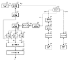
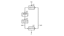
図1は、ホモダイン型で、干渉部分がI1〜I3の場合の本発明に係る光ファイバセンサの構成例(第1実施形態)である。 FIG. 1 is a configuration example (first embodiment) of an optical fiber sensor according to the present invention in the case of a homodyne type and interference portions I1 to I3.
レーザ光源101が発生する狭線幅の光信号Srに対して、光位相変調器102により、周期T中のt3区間のみの位相を、他のt1、t2及びt4区間に比較して90度変化させる。位相を変化させるタイミング及び変化させる時間τはパルス発生器113により管理される。間歇的に位相変化を与えられた光信号(計測用光信号)Sra1は、光カプラ103に供給され2分岐される。光カプラ103は、ファイバカプラやビームスプリッタ等で構成される。
With respect to the optical signal Sr having a narrow line width generated by the
光カプラ103の片方の分岐光信号は、コリメータ106により空間を進行し、反射ミラー108にて反射され、再度コリメータ106を経て光カプラ103に参照光SrR1として帰ってくる。他方、光カプラ103で分岐された他の分岐光信号は光遅延ファイバ等の遅延線104によって、参照光SrR1に対してτ/2の遅延を与えられた後、ファイバセンサ105に導かれる。ファイバセンサ105は、光ファイバに加えられた外圧により、ファイバの屈折率或いは実効長が変化するようなセンサである。ファイバセンサ105を通過した分岐光信号は、コリメータ107により空中を伝搬し、反射ミラー109で反射され、コリメータ107及びファイバセンサ105を経由し、遅延線104で再度τ/2の遅延を受けて計測光SrM1として光カプラ103に供給される。なお、遅延線は、参照光側に挿入することも可能で、その場合も同じ光ファイバセンサを構成出来る。
One branched optical signal of the
コリメータ106からの参照光SrR1及び遅延線104からの計測光SrM1は、共に光カプラ103に加えられ、その合成光出力が干渉光信号Li1として光/電気(O/E)変換器114に供給され、干渉光信号Li1に応じた電気信号Ea1を得る。光/電気変換器114は、光信号を2乗検波するダイオード検波器である。光/電気変換器114から出力される電気信号Ea1は、RFアンプ115で所要の大きさまで増幅された後、A/D変換器116でアナログ信号からデジタル信号の電気信号Ed1に変換される。電気信号Ed1は、レジスタ117、118及び119に供給され、パルス発生器113から送られてくるタイミング信号に従って、後述するタイムチャートでの干渉部分I1、I2及びI3の電気信号値i1、i2及びi3を、それぞれのレジスタ上に得る。レジスタ117〜119に格納された電気信号値i1〜i3により、次の差分演算器121により、干渉位相を示す電気信号間の差分、つまりi1−i2及びi3−i1が計算される。差分演算器121で求められたi1−i2及びi3−i1よりATAN演算器122が、(i1−i2)/(i3−i1)の逆正接計算を行ない、数10の関係から参照光SrR1と計測光SrM1の位相差θ1を計算する。ATAN演算器122の出力が求めている最終結果となる。
Both the reference light SrR1 from the
図1に示される構成例において、レーザ光源101及び光位相変調器102で計測用光信号発生部を構成し、光カプラ103、遅延線104、ファイバセンサ105、コリメータ106及び107、並びに反射ミラー108及び109で光干渉部を構成し、光/電気変換器114、RFアンプ115、A/D変換器116、レジスタ117〜119、差分演算器121及びATAN演算器122で位相差演算部を構成している。
In the configuration example shown in FIG. 1, a
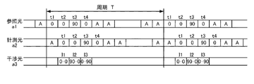
このような構成において、その動作例を、図2のタイムチャートを参照して説明する。 In such a configuration, an example of the operation will be described with reference to the time chart of FIG.
図2は、第1実施形態の動作例を示すタイムチャートである。a1は周期Tにおける参照光SrR1の位相を示し、a2は計測光SrM1の位相を示し、a3は干渉結果として得られる干渉光信号Li1の干渉部分(I1〜I3)の位相を示す。「0」は位相を変化させられていない基準位相を表わし、「90」は90度位相を変化させられた位相(以下、「90度位相」とする)を表わし、「A」は任意の位相を表わす。 FIG. 2 is a time chart showing an operation example of the first embodiment. a1 indicates the phase of the reference light SrR1 in the period T, a2 indicates the phase of the measurement light SrM1, and a3 indicates the phase of the interference portion (I1 to I3) of the interference optical signal Li1 obtained as an interference result. “0” represents a reference phase whose phase has not been changed, “90” represents a phase whose phase has been changed by 90 ° (hereinafter referred to as “90 ° phase”), and “A” represents an arbitrary phase. Represents.
a1に示すように、参照光SrR1は周期T内のt1、t2及びt4区間の位相が基準位相、t3区間の位相が90度位相になるように作成される。また、a2に示す計測光SrM1は、参照光SrR1を各区間の時間間隔であるτだけ遅延させたものとなる。a3は、上記a1に示す参照光SrR1及びa2に示す計測光SrM1を干渉させた干渉光信号Li1の様子を示している。干渉光信号Li1のうち、参照光SrR1のt2の位置と計測光SrM1のt1の位置が干渉した結果が干渉部分I1であり、同様に、t3とt2が干渉した結果が干渉部分I2、t4とt3が干渉した結果が干渉部分I3である。これら干渉部分の電気信号値i1、i2及びi3から、参照光SrR1と計測光SrM1の位相差θ1が求められる。 As indicated by a1, the reference light SrR1 is created such that the phases of the t1, t2, and t4 intervals within the period T are the reference phase, and the phase of the t3 interval is 90 degrees. Further, the measurement light SrM1 indicated by a2 is obtained by delaying the reference light SrR1 by τ that is the time interval of each section. a3 shows the state of the interference light signal Li1 obtained by causing the reference light SrR1 shown in a1 and the measurement light SrM1 shown in a2 to interfere with each other. Of the interference light signal Li1, the result of interference between the position t2 of the reference light SrR1 and the position t1 of the measurement light SrM1 is the interference part I1, and similarly, the result of interference between t3 and t2 is the interference parts I2, t4 and The result of interference of t3 is the interference portion I3. From the electric signal values i1, i2, and i3 of these interference portions, the phase difference θ1 between the reference light SrR1 and the measurement light SrM1 is obtained.
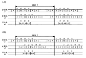
なお、周期T中での90度位相の区間は図2に示されるようなt3区間に限られず、干渉光信号において、参照光と計測光の位相の組み合わせとして「0−0」、「90−0」及び「0−90」の3パターンが形成されるのであれば、90度位相の区間の位置を変えたり、同区間の数を増やしたりしても良い。例えば、図3(A)に示されるように、t2区間の位相を90度位相としても良い。或いは、図3(B)に示されるように、t3区間の位相を90度位相とし、t4区間の隣のt5区間の位相を基準位相とし、計測光の遅延を2τとして、干渉光信号中に「0−0」、「90−0」及び「0−90」の3パターンを形成するようにしても良い。 Note that the 90-degree phase interval in the period T is not limited to the t3 interval as shown in FIG. 2, and “0-0” and “90-” are combinations of the phases of the reference light and the measurement light in the interference light signal. If three patterns of “0” and “0-90” are formed, the positions of 90 degree phase sections may be changed, or the number of the same sections may be increased. For example, as shown in FIG. 3A, the phase in the t2 interval may be 90 degrees. Alternatively, as shown in FIG. 3B, the phase of the t3 section is 90 degrees, the phase of the t5 section adjacent to the t4 section is the reference phase, the delay of the measurement light is 2τ, and the interference light signal includes Three patterns of “0-0”, “90-0”, and “0-90” may be formed.
本発明の他の実施形態について説明する。 Another embodiment of the present invention will be described.
図4は、ホモダイン型で、干渉部分がI1〜I4の場合の本発明に係る光ファイバセンサの構成例(第2実施形態)である。 FIG. 4 is a configuration example (second embodiment) of the optical fiber sensor according to the present invention in the case of a homodyne type and interference portions I1 to I4.
レーザ光源101が発生する狭線幅の光信号Srに対して、光位相変調器202により、周期T中のt3区間のみの位相を、他のt1、t2、t4及びt5区間に比較して90度変化させる。位相を変化させるタイミング及び変化させる時間τはパルス発生器113により管理される。間歇的に位相変化を与えられた光信号(計測用光信号)Sra2は、光カプラ103に供給され2分岐される。
With respect to the optical signal Sr with a narrow line width generated by the
光カプラ103の片方の分岐光信号は、コリメータ106により空間を進行し、反射ミラー108にて反射され、再度コリメータ106を経て光カプラ103に参照光SrR2として帰ってくる。他方、光カプラ103で分岐された他の分岐光信号は遅延線104によって、参照光SrR2に対してτ/2の遅延を与えられた後、ファイバセンサ105に導かれる。ファイバセンサ105を通過した分岐光信号は、コリメータ107により空中を伝搬し、反射ミラー109で反射され、コリメータ107及びファイバセンサ105を経由し、遅延線104で再度τ/2の遅延を受けて計測光SrM2として光カプラ103に供給される。
One branched optical signal of the
コリメータ106からの参照光SrR2及び遅延線104からの計測光SrM2は、共に光カプラ103に加えられ、その合成光出力が干渉光信号Li2として光/電気変換器114に供給され、干渉光信号Li2に応じた電気信号Ea2を得る。光/電気変換器114から出力される電気信号Ea2は、RFアンプ115で所要の大きさまで増幅された後、A/D変換器116でアナログ信号からデジタル信号の電気信号Ed2に変換される。電気信号Ed2は、レジスタ117、118、119及び120に供給され、パルス発生器113から送られてくるタイミング信号に従って、後述するタイムチャートでの干渉部分I1、I2、I3及びI4の電気信号値i1、i2、i3及びi4を、それぞれのレジスタ上に得る。レジスタ117〜120に格納された電気信号値i1〜i4により、次の差分演算器221により、干渉位相を示す電気信号間の差分、つまりi1−i2及びi3−i4が計算される。差分演算器221で求められたi1−i2及びi3−i4よりATAN演算器122が(i1−i2)/(i3−i4)の逆正接計算を行ない、数11の関係から参照光SrR2と計測光SrM2の位相差θ1を計算する。ATAN演算器122の出力が求めている最終結果となる。
Both the reference light SrR2 from the
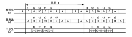
このような構成において、その動作例を、図5のタイムチャートを参照して説明する。 In such a configuration, an example of the operation will be described with reference to the time chart of FIG.
図5は、第2実施形態の動作例を示すタイムチャートである。b1は周期Tにおける参照光SrR2の位相を示し、b2は計測光SrM2の位相を示し、b3は干渉結果として得られる干渉光信号Li2の干渉部分(I1〜I4)の位相を示す。「0」、「90」及び「A」の意味は、図2の場合と同じである。 FIG. 5 is a time chart showing an operation example of the second embodiment. b1 indicates the phase of the reference light SrR2 in the period T, b2 indicates the phase of the measurement light SrM2, and b3 indicates the phase of the interference portion (I1 to I4) of the interference optical signal Li2 obtained as an interference result. The meanings of “0”, “90”, and “A” are the same as those in FIG.
b1に示すように、参照光SrR2は周期T内のt1、t2、t4及びt5区間の位相が基準位相、t3区間の位相が90度位相になるように作成される。また、b2に示す計測光SrM2は、参照光SrR2を各区間の時間間隔であるτだけ遅延させたものとなる。b3は、上記b1に示す参照光SrR2及びb2に示す計測光SrM2を干渉させた干渉光信号Li2の様子を示している。干渉光信号Li2のうち、参照光SrR2のt2位置と計測光SrM2のt1位置が干渉した結果が干渉部分I1であり、同様に、t3とt2が干渉した結果が干渉部分I2、t4とt3が干渉した結果が干渉部分I3、t5とt4が干渉した結果が干渉部分I4である。これら干渉部分の電気信号値i1、i2、i3及びi4から、参照光SrR2と計測光SrM2の位相差θ1が求められる。 As shown in b1, the reference light SrR2 is created such that the phases in the periods t1, t2, t4, and t5 in the period T are the standard phase, and the phase in the t3 period is 90 degrees. Further, the measurement light SrM2 indicated by b2 is obtained by delaying the reference light SrR2 by τ that is the time interval of each section. b3 shows a state of the interference light signal Li2 obtained by causing the reference light SrR2 shown in b1 and the measurement light SrM2 shown in b2 to interfere with each other. Of the interference light signal Li2, the result of interference between the t2 position of the reference light SrR2 and the t1 position of the measurement light SrM2 is the interference part I1, and similarly, the result of interference between t3 and t2 is the interference part I2, t4 and t3. The interference result is interference part I3, and the result of interference between t5 and t4 is interference part I4. The phase difference θ1 between the reference light SrR2 and the measurement light SrM2 is obtained from the electric signal values i1, i2, i3 and i4 of these interference portions.
なお、周期T中での90度位相の区間は図5に示されるようなt3区間に限られず、干渉光信号において、参照光と計測光の位相の組み合わせとして「0−0」、「90−0」、「0−90」及び「0−0」の4パターンが形成されるのであれば、90度位相の区間の位置を変えたり、同区間の数を増やしたりしても良い。 Note that the 90-degree phase interval in the period T is not limited to the t3 interval as shown in FIG. 5, and “0-0” and “90-” are combinations of the phases of the reference light and the measurement light in the interference light signal. If four patterns of “0”, “0-90”, and “0-0” are formed, the positions of 90 degree phase sections may be changed, or the number of the same sections may be increased.
第1実施形態及び第2実施形態はホモダイン型の構成例であるが、干渉計の構成方法には、ホモダイン型の他に、マッハツェンダ型がある。ホモダイン型は、入出力の分離が十分行えない場合があるが、マッハツェンダ型は、入出力で別の光カプラを使用するので、入出力の分離が容易である。 The first and second embodiments are homodyne type configuration examples, but the interferometer configuration method includes a Mach-Zehnder type in addition to the homodyne type. The homodyne type may not be able to sufficiently separate the input and output, but the Mach-Zehnder type uses a separate optical coupler for the input and output, so that the input and output are easily separated.
図6は、マッハツェンダ型センサでの光干渉部の概略の構成例(第3実施形態)である。光カプラ103に供給された間歇的に位相変化を与えられた光信号(計測用光信号)Sraは、光カプラ103で2分岐され、一方の分岐光信号は、次の光カプラ110に参照光SrRとして供給される。他方の分岐光信号は、τの遅延を有する遅延線204を経てファイバセンサ105に供給される。ファイバセンサ105は、光ファイバに加えられた外圧により、ファイバの屈折率或いは実効長が変化するようなセンサであり、検出すべき計測項目によりその光路長が変化するものである。ファイバセンサ105の出力光信号も、また計測光SrMとして光カプラ110に供給され、光カプラ110の出力として、ファイバセンサ105で位相変調された干渉光信号Liが得られる。
FIG. 6 is a schematic configuration example (third embodiment) of an optical interference unit in a Mach-Zehnder type sensor. The optical signal (measurement optical signal) Sra that is intermittently given a phase change supplied to the
上述の実施形態(第1〜第3実施形態)は、ファイバが受ける各種の歪みで、計測すべき事象を検出する例である。これらに対して、図7に示す構成例は、本発明に係るホモダイン型光ファイバセンサにより、物体の相対位置変動を検出する光干渉部の構成例(第4実施形態)である。 The above-described embodiments (first to third embodiments) are examples of detecting an event to be measured with various strains received by a fiber. On the other hand, the configuration example shown in FIG. 7 is a configuration example (fourth embodiment) of the optical interference unit that detects the relative position fluctuation of the object by the homodyne type optical fiber sensor according to the present invention.
光カプラ103に加えられた光信号Sraを同光カプラで2分岐し、一方の分岐光信号を、コリメータ106を介して空中伝搬させ、反射ミラー108で反射させ、再度空中を伝搬してコリメータ106を介して光カプラ103へ参照光SrRとして戻す。他方の分岐光信号はτ/2の遅延を有する遅延線104を経て、コリメータ107で空中を伝搬させられる。この空中を伝搬した光信号は、相対距離変動を計測すべき物体に固定した光学プリズム又はコーナーキューブ111により、その光学プリズム等に入射した光信号と同じ方向に反射させられる。この光学プリズム111で反射した光信号を、更に反射ミラー109で反射する。この反射波は、再度、光学プリズム111、コリメータ107及び遅延線104を通って、光カプラ103に計測光SrMとして戻される。光カプラ103は、参照光SrR及び計測光SrMの両者を干渉させて、出力端子から干渉光信号Liを出力する。
The optical signal Sra applied to the
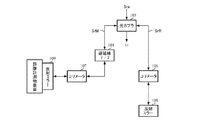
図8は、図7に示される距離計測用ホモダイン型光ファイバセンサを、マッハツェンダ型に変更した光干渉部の構成例(第5実施形態)である。光カプラ103で2分岐された光信号の一方は、次の光カプラ110へ参照光SrRとして供給される。光カプラ103で2分岐された、他の一方の光信号は、τの遅延を有する遅延線204を介して、コリメータ107で空中を伝搬させられる。この空中を伝搬した光信号は、相対距離変動を計測すべき物体に固定した光学プリズム又はコーナーキューブ111により、その光学プリズム等に入射した光信号と同じ方向に反射させられる。この光学プリズム111で反射した光信号を別のコリメータ112で受波し、その光信号を計測光SrMとして光カプラ110に供給する。光カプラ110は、参照光SrR及び計測光SrMの両者を干渉させて、出力端子から干渉信号Liを出力する。
FIG. 8 is a configuration example (fifth embodiment) of an optical interference unit in which the homodyne type optical fiber sensor for distance measurement shown in FIG. 7 is changed to a Mach-Zehnder type. One of the optical signals branched into two by the
図7に示される構成例では、コリメータ107から空間に出た計測光を、相対距離変動を計測すべき物体に固定した光学プリズム又はコーナーキューブ111で反射しているが、図9に示すように、光学プリズム又はコーナーキューブ111を削除して、反射ミラー109を直接距離計測物表面に実装することも可能である。
In the configuration example shown in FIG. 7, the measurement light emitted from the
これまでの説明では光ファイバによる偏波変動が測定結果に及ぼす影響についての説明を行っていないが、光ファイバによる偏波変動は測定値に影響を与え、結果として誤差を生ずる場合がある。偏波変動による測定誤差を無くす、或いは小さくするには、光ファイバに偏波保持型のものを使用すれば良い。或いは、図7に示される構成例において、図10に示すように、反射ミラー108及び109の代わりに、ファラデーローテータミラー208及び209を使用することにより、偏波保持型ファイバを使用しない、つまりシングルモードファイバを使用して、誤差の少ない測定が可能となる。 The description so far has not described the influence of the polarization fluctuation caused by the optical fiber on the measurement result, but the polarization fluctuation caused by the optical fiber affects the measurement value, and may result in an error. In order to eliminate or reduce the measurement error due to polarization fluctuation, a polarization maintaining type optical fiber may be used. Alternatively, in the configuration example shown in FIG. 7, as shown in FIG. 10, by using the Faraday rotator mirrors 208 and 209 instead of the reflection mirrors 108 and 109, the polarization maintaining fiber is not used. Measurements with less error are possible using mode fiber.
上述の実施形態(第1〜第5実施形態)では、計測対象の変化(つまり、光路長変化)が計測光のみに与えられる場合を例にして説明したが、参照光側と計測光側がお互いに逆相になるような変化、例えば、位置が変化する物体の表と裏の変化、を参照光と計測光の両方に与えることにより、センサの感度を2倍に向上することが可能である。 In the above-described embodiments (first to fifth embodiments), the case in which the change of the measurement target (that is, the change in the optical path length) is given only to the measurement light has been described as an example. It is possible to improve the sensitivity of the sensor by a factor of 2 by providing both the reference light and the measurement light with changes that are in opposite phases to each other, for example, changes in the front and back of the object whose position changes. .
また、上述の実施形態では、計測用のレーザ光として連続光線を使用しているが、t1〜t4区間(又はt1〜t5区間)に対応する光パルスを利用してシステムを構築することも可能である。この場合、コスト低減の効果は少なくなるが、周期T中に複数のt1〜t4区間(又はt1〜t5区間)の光パルスを収容すれば、1つのシステムで複数の計測を行う時分割多重測定が可能となる。 In the above-described embodiment, a continuous light beam is used as the measurement laser beam. However, it is also possible to construct a system using an optical pulse corresponding to the t1 to t4 section (or t1 to t5 section). It is. In this case, the cost reduction effect is reduced, but if a plurality of t1-t4 section (or t1-t5 section) optical pulses are accommodated in the period T, time division multiplex measurement in which a plurality of measurements are performed in one system. Is possible.
更に、上述の実施形態においては、ファイバの光路長変化を検出するセンサ、物体の相対変動を検出するセンサ(距離計や振動センサ)の例を示したが、本発明は、その他温度センサ等、多くのセンサに適用可能である。 Furthermore, in the above-described embodiment, an example of a sensor that detects a change in the optical path length of a fiber and a sensor (a distance meter or a vibration sensor) that detects a relative fluctuation of an object has been shown. Applicable to many sensors.
本発明は、海底地震観測等、離れた場所、電源供給ができない場所、電磁雑音の影響を受け易い場所、温度環境が厳しい場所、引火の可能性がある場所等に設置するセンサシステムに適する。 The present invention is suitable for a sensor system installed in a remote place such as an ocean bottom earthquake observation, a place where power supply cannot be performed, a place susceptible to electromagnetic noise, a place where temperature is severe, a place where ignition is possible, and the like.
101 レーザ光源
102 光位相変調器
103、110 光カプラ
104、204 遅延線
105 ファイバセンサ
106、107、112 コリメータ
108、109 反射ミラー
111 光学プリズム
113 パルス発生器
114 光/電気変換器
115 RFアンプ
116 A/D変換器
117、118、119、120 レジスタ
121、221 差分演算器
122 ATAN演算器
208、209 ファラデーローテータミラー
DESCRIPTION OF
Claims (5)
前記計測用光信号の分波である計測光及び参照光の間に前記所定の時間間隔の整数倍の時間だけ遅延を設け、外力により光路長を変動させられた前記計測光と前記参照光を結合して干渉光信号を生成する光干渉部と、
前記干渉光信号に基づいて、前記計測光と前記参照光の位相差を算出する位相差演算部とを備え、
前記位相差演算部は、90度位相変調していない同位相区間における前記計測光及び前記同位相区間における前記参照光の結合により生成される前記干渉光信号の電気信号1と、前記同位相区間における前記計測光及び前記直交位相区間における前記参照光の結合により生成される前記干渉光信号の電気信号2と、前記直交位相区間における前記計測光及び前記同位相区間における前記参照光の結合により生成される前記干渉光信号の電気信号3を少なくとも用い、前記電気信号1及び前記電気信号2の差分並びに前記電気信号3及び前記電気信号1の差分より前記位相差を算出する光ファイバセンサ。 An optical signal generator for measurement that generates an optical signal for measurement having at least one quadrature phase section that is divided by a predetermined time interval and phase-modulated by 90 degrees compared to the phases of other sections;
A delay is provided between the measurement light, which is a demultiplexing of the measurement optical signal, and the reference light by a time that is an integral multiple of the predetermined time interval, and the measurement light and the reference light whose optical path length is varied by an external force. An optical interference unit that combines to generate an interference optical signal;
A phase difference calculation unit that calculates a phase difference between the measurement light and the reference light based on the interference light signal;
The phase difference calculation unit includes an electrical signal 1 of the interference light signal generated by combining the measurement light in the same phase section that is not phase-modulated by 90 degrees and the reference light in the same phase section, and the same phase section. Generated by combining the measurement light in the quadrature phase and the reference light in the quadrature phase section and the reference signal in the quadrature phase section An optical fiber sensor that uses at least the electrical signal 3 of the interference optical signal and calculates the phase difference from the difference between the electrical signal 1 and the electrical signal 2 and the difference between the electrical signal 3 and the electrical signal 1.
前記光干渉部は、前記計測光及び前記参照光の間に前記所定の時間間隔だけ遅延を設ける請求項1に記載の光ファイバセンサ。 The measurement optical signal generation unit generates the measurement optical signal in which the third section is the quadrature phase section and the other three sections are the same phase section among the four consecutive sections,
The optical fiber sensor according to claim 1, wherein the optical interference unit provides a delay for the predetermined time interval between the measurement light and the reference light.
前記光干渉部は、前記計測光及び前記参照光の間に前記所定の時間間隔だけ遅延を設ける請求項1又は2に記載の光ファイバセンサ。 The measurement optical signal generation unit generates the measurement optical signal in which the third section is the quadrature phase section and the other four sections are the same phase section among the five consecutive sections,
The optical fiber sensor according to claim 1, wherein the optical interference unit provides a delay for the predetermined time interval between the measurement light and the reference light.
Priority Applications (1)
| Application Number | Priority Date | Filing Date | Title |
|---|---|---|---|
| JP2016139602A JP6763567B2 (en) | 2016-07-14 | 2016-07-14 | Fiber optic sensor |
Applications Claiming Priority (1)
| Application Number | Priority Date | Filing Date | Title |
|---|---|---|---|
| JP2016139602A JP6763567B2 (en) | 2016-07-14 | 2016-07-14 | Fiber optic sensor |
Publications (2)
| Publication Number | Publication Date |
|---|---|
| JP2018009896A true JP2018009896A (en) | 2018-01-18 |
| JP6763567B2 JP6763567B2 (en) | 2020-09-30 |
Family
ID=60995392
Family Applications (1)
| Application Number | Title | Priority Date | Filing Date |
|---|---|---|---|
| JP2016139602A Active JP6763567B2 (en) | 2016-07-14 | 2016-07-14 | Fiber optic sensor |
Country Status (1)
| Country | Link |
|---|---|
| JP (1) | JP6763567B2 (en) |
Cited By (6)
| Publication number | Priority date | Publication date | Assignee | Title |
|---|---|---|---|---|
| JP2021047145A (en) * | 2019-09-20 | 2021-03-25 | 国立大学法人東京農工大学 | Laser interference type displacement gauge and displacement measuring method |
| CN116182916A (en) * | 2023-04-27 | 2023-05-30 | 四川省医学科学院·四川省人民医院 | A Photonic Sensing System for Broadband Phase Modulation Processing |
| JP2023131864A (en) * | 2022-03-10 | 2023-09-22 | 沖電気工業株式会社 | Optical fiber sensor and method for measuring brillouin frequency shift |
| JP2023140366A (en) * | 2022-03-17 | 2023-10-05 | 沖電気工業株式会社 | Optical fiber sensor and Brillouin frequency shift measurement method |
| JP7371830B1 (en) | 2023-01-31 | 2023-10-31 | 白山工業株式会社 | Optical fiber sensor and measurement system using it |
| US20240255320A1 (en) * | 2023-01-31 | 2024-08-01 | Hakusan Corporation | Optical fiber sensor and measuring system using the same |
Citations (7)
| Publication number | Priority date | Publication date | Assignee | Title |
|---|---|---|---|---|
| JPH07229713A (en) * | 1994-02-22 | 1995-08-29 | Sumitomo Metal Mining Co Ltd | Displacement measuring method and displacement measuring apparatus using the same |
| JP2007040994A (en) * | 2005-08-01 | 2007-02-15 | Mitsutoyo Corp | Interference measurement system |
| JP2008286518A (en) * | 2007-05-15 | 2008-11-27 | Hitachi Ltd | Displacement measuring method and apparatus |
| US20100238455A1 (en) * | 2009-03-20 | 2010-09-23 | Zygo Corporation | Error compensation in phase shifting interferometry |
| JP2011214921A (en) * | 2010-03-31 | 2011-10-27 | Oki Electric Industry Co Ltd | Interference type optical fiber sensor system and calculator |
| JP2011242383A (en) * | 2010-04-21 | 2011-12-01 | Hakusan Kogyo Kk | Optical fiber sensor |
| JP2013113838A (en) * | 2011-11-25 | 2013-06-10 | Hakusan Kogyo Kk | Optical fiber sensor |
-
2016
- 2016-07-14 JP JP2016139602A patent/JP6763567B2/en active Active
Patent Citations (7)
| Publication number | Priority date | Publication date | Assignee | Title |
|---|---|---|---|---|
| JPH07229713A (en) * | 1994-02-22 | 1995-08-29 | Sumitomo Metal Mining Co Ltd | Displacement measuring method and displacement measuring apparatus using the same |
| JP2007040994A (en) * | 2005-08-01 | 2007-02-15 | Mitsutoyo Corp | Interference measurement system |
| JP2008286518A (en) * | 2007-05-15 | 2008-11-27 | Hitachi Ltd | Displacement measuring method and apparatus |
| US20100238455A1 (en) * | 2009-03-20 | 2010-09-23 | Zygo Corporation | Error compensation in phase shifting interferometry |
| JP2011214921A (en) * | 2010-03-31 | 2011-10-27 | Oki Electric Industry Co Ltd | Interference type optical fiber sensor system and calculator |
| JP2011242383A (en) * | 2010-04-21 | 2011-12-01 | Hakusan Kogyo Kk | Optical fiber sensor |
| JP2013113838A (en) * | 2011-11-25 | 2013-06-10 | Hakusan Kogyo Kk | Optical fiber sensor |
Cited By (9)
| Publication number | Priority date | Publication date | Assignee | Title |
|---|---|---|---|---|
| JP2021047145A (en) * | 2019-09-20 | 2021-03-25 | 国立大学法人東京農工大学 | Laser interference type displacement gauge and displacement measuring method |
| JP7335598B2 (en) | 2019-09-20 | 2023-08-30 | 国立大学法人東京農工大学 | LASER INTERFERENCE DISPLACEMENT METHOD AND DISPLACEMENT MEASUREMENT METHOD |
| JP2023131864A (en) * | 2022-03-10 | 2023-09-22 | 沖電気工業株式会社 | Optical fiber sensor and method for measuring brillouin frequency shift |
| JP2023140366A (en) * | 2022-03-17 | 2023-10-05 | 沖電気工業株式会社 | Optical fiber sensor and Brillouin frequency shift measurement method |
| JP7371830B1 (en) | 2023-01-31 | 2023-10-31 | 白山工業株式会社 | Optical fiber sensor and measurement system using it |
| US20240255320A1 (en) * | 2023-01-31 | 2024-08-01 | Hakusan Corporation | Optical fiber sensor and measuring system using the same |
| EP4411314A2 (en) | 2023-01-31 | 2024-08-07 | Hakusan Corporation | Optical fiber sensor and measuring system using the same |
| JP2024108999A (en) * | 2023-01-31 | 2024-08-13 | 白山工業株式会社 | Optical fiber sensor and measurement system using same |
| CN116182916A (en) * | 2023-04-27 | 2023-05-30 | 四川省医学科学院·四川省人民医院 | A Photonic Sensing System for Broadband Phase Modulation Processing |
Also Published As
| Publication number | Publication date |
|---|---|
| JP6763567B2 (en) | 2020-09-30 |
Similar Documents
| Publication | Publication Date | Title |
|---|---|---|
| JP6763567B2 (en) | Fiber optic sensor | |
| US11193818B2 (en) | Frequency modulation demodulator based on fiber grating sensor array | |
| US10162245B2 (en) | Distributed acoustic sensing system based on delayed optical hybrid phase demodulator | |
| US10168137B2 (en) | Dual laser frequency sweep interferometry system and method | |
| CN101799318B (en) | Laser homodyne vibration detection optical system | |
| CN111157101A (en) | Weak grating array distributed vibration sensing system and method | |
| US20150043004A1 (en) | High speed high resolution heterodyne interferometric method and system | |
| US10634525B2 (en) | Detection of local property changes in an optical sensing fiber | |
| CN108873007B (en) | A Frequency Modulated Continuous Wave Laser Distance Measuring Device Suppressing Vibration Effect | |
| CN109297581A (en) | A Quadratic Phase Difference Measurement Method for Compensating Frequency Drift in Phase-Sensitive Optical Time Domain Reflectometers | |
| CN105093238A (en) | Transflective dual-edge doppler wind lidar based on single-cavity F-P interferometer and single detector | |
| WO2009142612A1 (en) | Dynamic polarization based fiber optic sensor | |
| JP7720588B2 (en) | Non-contact distance measuring device and method | |
| CN111912516A (en) | A phase-synchronized optical fiber distributed vibration measurement device, driver and method | |
| US9273948B2 (en) | Optical fiber sensor | |
| JPH03180704A (en) | laser interferometer | |
| WO2022259437A1 (en) | Vibration measurement device and vibration measurement method | |
| CN103234452B (en) | solid laser feedback interferometer | |
| JP5088915B2 (en) | Displacement measuring device | |
| JP7811487B2 (en) | Apparatus for interferometric distance measurement. | |
| CN110133678A (en) | A method for improving the measurement range of a phase-modulated laser Doppler velocimetry system | |
| CN116907627A (en) | Optical path difference auxiliary-based large dynamic range distributed phase sensing method and device | |
| CN212254333U (en) | Phase synchronization optical fiber distributed vibration measuring device and driver | |
| CN115900784A (en) | An OFDR Sensing System Based on Mach-Zehnder Interference | |
| JP2006308531A (en) | Chromatic dispersion measurement method and apparatus |
Legal Events
| Date | Code | Title | Description |
|---|---|---|---|
| A621 | Written request for application examination |
Free format text: JAPANESE INTERMEDIATE CODE: A621 Effective date: 20190412 |
|
| A977 | Report on retrieval |
Free format text: JAPANESE INTERMEDIATE CODE: A971007 Effective date: 20200319 |
|
| A131 | Notification of reasons for refusal |
Free format text: JAPANESE INTERMEDIATE CODE: A131 Effective date: 20200331 |
|
| A521 | Request for written amendment filed |
Free format text: JAPANESE INTERMEDIATE CODE: A523 Effective date: 20200427 |
|
| TRDD | Decision of grant or rejection written | ||
| A01 | Written decision to grant a patent or to grant a registration (utility model) |
Free format text: JAPANESE INTERMEDIATE CODE: A01 Effective date: 20200901 |
|
| A61 | First payment of annual fees (during grant procedure) |
Free format text: JAPANESE INTERMEDIATE CODE: A61 Effective date: 20200904 |
|
| R150 | Certificate of patent or registration of utility model |
Ref document number: 6763567 Country of ref document: JP Free format text: JAPANESE INTERMEDIATE CODE: R150 |
|
| R250 | Receipt of annual fees |
Free format text: JAPANESE INTERMEDIATE CODE: R250 |
|
| R250 | Receipt of annual fees |
Free format text: JAPANESE INTERMEDIATE CODE: R250 |
|
| R250 | Receipt of annual fees |
Free format text: JAPANESE INTERMEDIATE CODE: R250 |